Cisco Aironet 1550 Series Outdoor Mesh Access Point Power ...
10
Americas Headquarters: Cisco Systems, Inc., 170 West Tasman Drive, San Jose, CA 95134-1706 USA Cisco Aironet 1550 Series Outdoor Mesh Access Point Power Injector Installation Instructions This document describes the Cisco Aironet 1550 Series Outdoor Mesh Access Point Power Injector (referred to as the power injector in this document) and provides instructions for mounting it. The power injector increases wireless LAN deployment flexibility of the access point by combining 56-VDC power with the data signal, sending both to the Cisco Aironet 1550 Series Outdoor Mesh Access Point (referred to as access point in this document). The following information is provided in this document: • Technical Specifications, page 2 • Regulatory Information, page 2 • Safety Precautions, page 3 • Overview, page 4 • Unpacking the Power Injector, page 5 • Mounting the Power Injector, page 6 • Installing the Power Injector, page 7 • Grounding the Power Injector, page 7 • Checking the Power Injector LEDs, page 8 • Power Injector Input and Output Connections, page 8 • Obtaining Documentation, Obtaining Support, and Security Guidelines, page 9
-
Upload
khangminh22 -
Category
Documents
-
view
5 -
download
0
Transcript of Cisco Aironet 1550 Series Outdoor Mesh Access Point Power ...
Cisco Aironet 1550 Series Outdoor Mesh Access Point Power Injector Installation Instructions
This document describes the Cisco Aironet 1550 Series Outdoor Mesh Access Point Power Injector (referred to as the power injector in this document) and provides instructions for mounting it. The power injector increases wireless LAN deployment flexibility of the access point by combining 56-VDC power with the data signal, sending both to the Cisco Aironet 1550 Series Outdoor Mesh Access Point (referred to as access point in this document).
The following information is provided in this document:
• Technical Specifications, page 2
• Regulatory Information, page 2
• Safety Precautions, page 3
• Overview, page 4
• Unpacking the Power Injector, page 5
• Mounting the Power Injector, page 6
• Installing the Power Injector, page 7
• Grounding the Power Injector, page 7
• Checking the Power Injector LEDs, page 8
• Power Injector Input and Output Connections, page 8
• Obtaining Documentation, Obtaining Support, and Security Guidelines, page 9
Americas Headquarters:Cisco Systems, Inc., 170 West Tasman Drive, San Jose, CA 95134-1706 USA
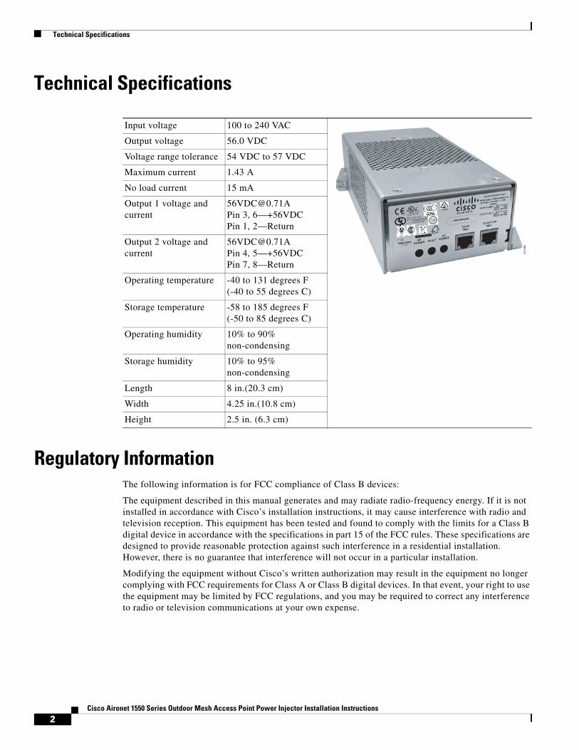
Technical Specifications
Technical Specifications
Regulatory Information The following information is for FCC compliance of Class B devices:
The equipment described in this manual generates and may radiate radio-frequency energy. If it is not installed in accordance with Cisco’s installation instructions, it may cause interference with radio and television reception. This equipment has been tested and found to comply with the limits for a Class B digital device in accordance with the specifications in part 15 of the FCC rules. These specifications are designed to provide reasonable protection against such interference in a residential installation. However, there is no guarantee that interference will not occur in a particular installation.
Modifying the equipment without Cisco’s written authorization may result in the equipment no longer complying with FCC requirements for Class A or Class B digital devices. In that event, your right to use the equipment may be limited by FCC regulations, and you may be required to correct any interference to radio or television communications at your own expense.
Input voltage 100 to 240 VAC
Output voltage 56.0 VDC
Voltage range tolerance 54 VDC to 57 VDC
Maximum current 1.43 A
No load current 15 mA
Output 1 voltage and current
[email protected] 3, 6—+56VDCPin 1, 2—Return
Output 2 voltage and current
[email protected] 4, 5—+56VDCPin 7, 8—Return
Operating temperature -40 to 131 degrees F(-40 to 55 degrees C)
Storage temperature -58 to 185 degrees F(-50 to 85 degrees C)
Operating humidity 10% to 90% non-condensing
Storage humidity 10% to 95% non-condensing
Length 8 in.(20.3 cm)
Width 4.25 in.(10.8 cm)
Height 2.5 in. (6.3 cm)
2314
85
2Cisco Aironet 1550 Series Outdoor Mesh Access Point Power Injector Installation Instructions
Safety Precautions
You can determine whether your equipment is causing interference by turning it off. If the interference stops, it was probably caused by the Cisco equipment or one of its peripheral devices. If the equipment causes interference to radio or television reception, try to correct the interference by using one or more of the following measures:
• Turn the television or radio antenna until the interference stops.
• Move the equipment to one side or the other of the television or radio.
• Move the equipment farther away from the television or radio.
• Plug the equipment into an outlet that is on a different circuit from the television or radio. (That is, make certain the equipment and the television or radio are on circuits controlled by different circuit breakers or fuses.)
Modifications to this product not authorized by Cisco Systems, Inc. could void the FCC approval and negate your authority to operate the product.
Safety PrecautionsTranslated versions of the following safety warnings are provided in the Safety Warnings for Cisco Aironet 1550 Series Outdoor Mesh Access Points document that ships with the access point and is available on cisco.com.
Warning IMPORTANT SAFETY INSTRUCTIONS This warning symbol means danger. You are in a situation that could cause bodily injury. Before you work on any equipment, be aware of the hazards involved with electrical circuitry and be familiar with standard practices for preventing accidents. Use the statement number provided at the end of each warning to locate its translation in the translated safety warnings that accompanied this device. Statement 1071
SAVE THESE INSTRUCTIONS
Warning Do not work on the system or connect or disconnect cables during periods of lightning activity. Statement 1001
Warning Read the installation instructions before connecting the system to the power source. Statement 1004
Warning This product relies on the building’s installation for short-circuit (overcurrent) protection. Ensure that the protective device is rated at not greater than 20A. Statement 1005
Warning Only trained and qualified personnel should be allowed to install, replace, and service this equipment. Statement 1030
Warning Ultimate disposal of this product should be handled according to all national laws and regulations. Statement 1040
3Cisco Aironet 1550 Series Outdoor Mesh Access Point Power Injector Installation Instructions
Overview
Warning To prevent the system from overheating, do not operate it in an area that exceeds the maximum recommended ambient temperature of: 131F (55C) Statement 1047
Warning To prevent airflow restriction, allow clearance around the ventilation openings to be at least:3 to 4 inches (7.6 to 10.1 centimeters) Statement 1076
Warning Installation of the equipment must comply with local and national electrical codes. Statement 1074
Caution Do not place the power injector in an unprotected outdoor environment because water could get into the power injector and cause a short circuit and possible fire.
Caution The power injector AC power receptacle must be accessible at all times, as it serves as the main disconnect device to the unit.
OverviewThe power injector combines 56-VDC power (supplied by internal power supply) with the data signal, sending both to the access point. The power injector provides up to 80 W over all four wire pairs of shielded, outdoor rated Ethernet cable. The power injector Ethernet cables are limited to a total length of 328 ft (100 m) maximum from the switch to the access point. Also, the Ethernet cable from the power injector to the access point is limited to a minimum of 10 ft. The wire gauge of the cable must be 26 AWG.
The Ethernet cable from the switch to the power injector must be a shielded CAT5e or higher Ethernet cable. The Ethernet cable from the power injector to the access point must be a shielded outdoor-rated CAT5e or higher Ethernet cable with a 0.20 to 0.35 inch diameter.
A shielded, outdoor Ethernet cable connects the power injector to a 10/100/1000 Ethernet switch, hub, or network, and another shielded, outdoor cable carries power and data to the access point’s Ethernet port. The power injector’s AC power receptacle connects an approved AC power cord to a wall outlet or power strip. The power injector can be mounted on most horizontal and vertical surfaces, but must be mounted in a vertical orientation to comply with safety requirements.
4Cisco Aironet 1550 Series Outdoor Mesh Access Point Power Injector Installation Instructions
Unpacking the Power Injector
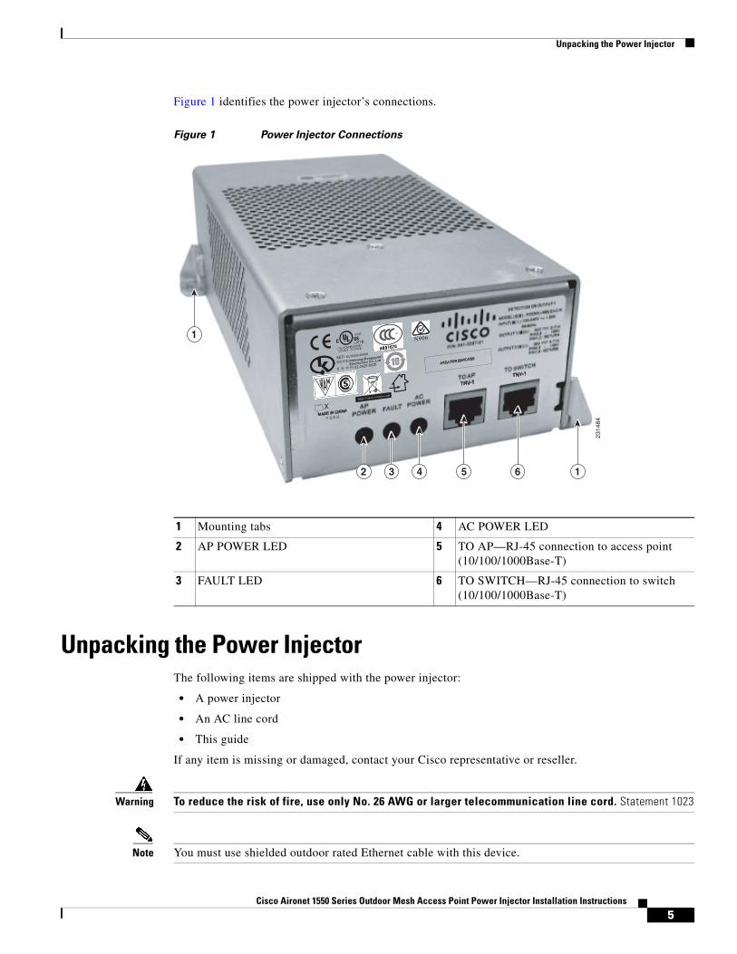
Figure 1 identifies the power injector’s connections.
Figure 1 Power Injector Connections
Unpacking the Power InjectorThe following items are shipped with the power injector:
• A power injector
• An AC line cord
• This guide
If any item is missing or damaged, contact your Cisco representative or reseller.
Warning To reduce the risk of fire, use only No. 26 AWG or larger telecommunication line cord. Statement 1023
Note You must use shielded outdoor rated Ethernet cable with this device.
1 Mounting tabs 4 AC POWER LED
2 AP POWER LED 5 TO AP—RJ-45 connection to access point (10/100/1000Base-T)
3 FAULT LED 6 TO SWITCH—RJ-45 connection to switch (10/100/1000Base-T)
2114
85
2314
84
1
12 3 4 5 6
5Cisco Aironet 1550 Series Outdoor Mesh Access Point Power Injector Installation Instructions
Mounting the Power Injector
Note The Cisco Aironet 1550 Series Power Injector is not suitable for operation in a building’s environmental air space and should not be installed in these environments.
Note Ethernet cable from the switch to the power injector must be a shielded CAT5e or higher Ethernet cable. The Ethernet cable from the power injector to the access point must be a shielded outdoor-rated CAT5e or higher Ethernet cable with a 0.20 to 0.35 inch diameter.
Note To comply with FCC regulations, the length of Ethernet cable connecting the power injector to the access point cannot be less than 10 ft (3 m).
Note The PoE-out port on the access point is disabled when using the power injector.
Mounting the Power Injector
Caution All mounting methods on any wall surface is subject to the acceptance of local jurisdiction.
Caution When mounting the power injector on a vertical surface such as a wall, do not mount it horizontally. It must be mounted vertically to comply with safety requirements.
You can mount the power injector to most vertical or horizontal surfaces. The power injector does not ship with a mounting kit. You must provide the fasteners for the surface on which you intend to mount the access point.
The power injector has two elongated mounting tabs, one on each end, that you can use to secure it to the surface. To mount the power injector using these tabs, you will need two fasteners at least 0.62-in (16 mm) long of the appropriate type for the surface on which you are mounting the power injector on.
To mount the power injector on a horizontal or vertical surface, follow these steps:
Step 1 Use the power injector to mark the positions of the mounting tab holes on the surface where you want to mount the power injector. Remember that the power injector must not be mounted horizontally.
Note The procedure may vary depending on what type of surface you are mounting the power injector on. Also, it may be helpful to refer to Figure 1 on page 5.
Step 2 To mount the power injector using an M4 or #6 wall anchor and screw, follow these steps:
a. Drill a 5/32-in. (0.15-mm) hole at the locations you marked.
b. Install the wall anchor in the hole.
c. Insert a fastener into the mounting tab holes. Tighten the screw just enough to keep it secure in the wall anchor. The fastener must be at least 0.62-in (16 mm) long.
6Cisco Aironet 1550 Series Outdoor Mesh Access Point Power Injector Installation Instructions
Grounding the Power Injector
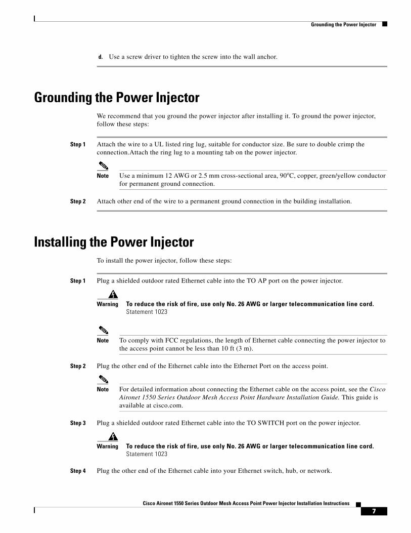
d. Use a screw driver to tighten the screw into the wall anchor.
Grounding the Power InjectorWe recommend that you ground the power injector after installing it. To ground the power injector, follow these steps:
Step 1 Attach the wire to a UL listed ring lug, suitable for conductor size. Be sure to double crimp the connection.Attach the ring lug to a mounting tab on the power injector.
Note Use a minimum 12 AWG or 2.5 mm cross-sectional area, 90oC, copper, green/yellow conductor for permanent ground connection.
Step 2 Attach other end of the wire to a permanent ground connection in the building installation.
Installing the Power InjectorTo install the power injector, follow these steps:
Step 1 Plug a shielded outdoor rated Ethernet cable into the TO AP port on the power injector.
Warning To reduce the risk of fire, use only No. 26 AWG or larger telecommunication line cord. Statement 1023
Note To comply with FCC regulations, the length of Ethernet cable connecting the power injector to the access point cannot be less than 10 ft (3 m).
Step 2 Plug the other end of the Ethernet cable into the Ethernet Port on the access point.
Note For detailed information about connecting the Ethernet cable on the access point, see the Cisco Aironet 1550 Series Outdoor Mesh Access Point Hardware Installation Guide. This guide is available at cisco.com.
Step 3 Plug a shielded outdoor rated Ethernet cable into the TO SWITCH port on the power injector.
Warning To reduce the risk of fire, use only No. 26 AWG or larger telecommunication line cord. Statement 1023
Step 4 Plug the other end of the Ethernet cable into your Ethernet switch, hub, or network.
7Cisco Aironet 1550 Series Outdoor Mesh Access Point Power Injector Installation Instructions
Checking the Power Injector LEDs
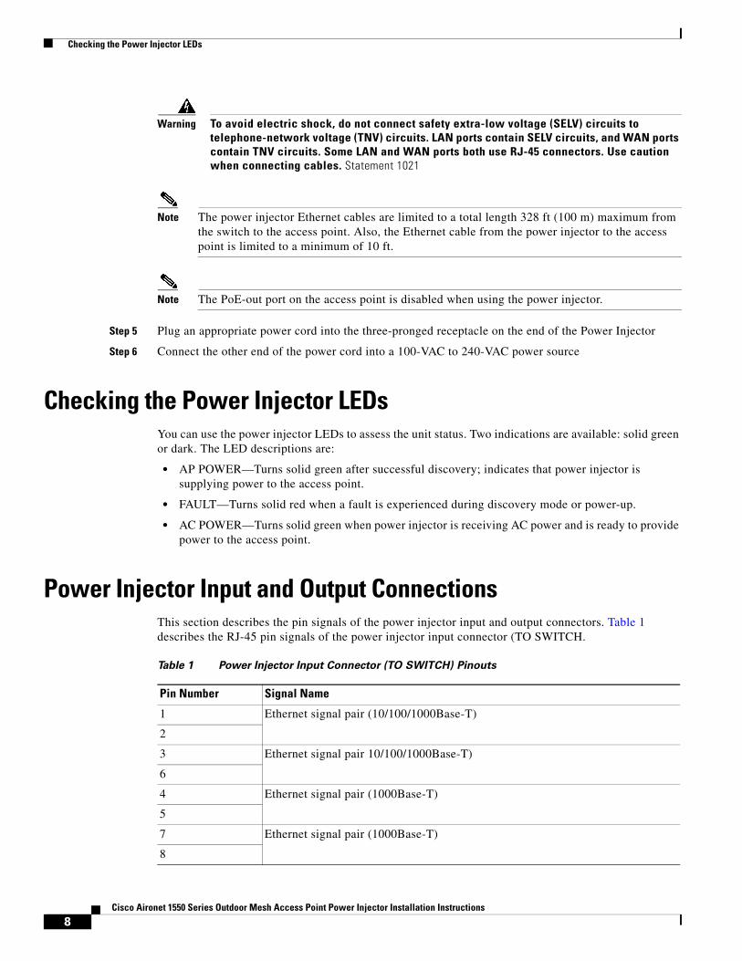
Warning To avoid electric shock, do not connect safety extra-low voltage (SELV) circuits to telephone-network voltage (TNV) circuits. LAN ports contain SELV circuits, and WAN ports contain TNV circuits. Some LAN and WAN ports both use RJ-45 connectors. Use caution when connecting cables. Statement 1021
Note The power injector Ethernet cables are limited to a total length 328 ft (100 m) maximum from the switch to the access point. Also, the Ethernet cable from the power injector to the access point is limited to a minimum of 10 ft.
Note The PoE-out port on the access point is disabled when using the power injector.
Step 5 Plug an appropriate power cord into the three-pronged receptacle on the end of the Power Injector
Step 6 Connect the other end of the power cord into a 100-VAC to 240-VAC power source
Checking the Power Injector LEDsYou can use the power injector LEDs to assess the unit status. Two indications are available: solid green or dark. The LED descriptions are:
• AP POWER—Turns solid green after successful discovery; indicates that power injector is supplying power to the access point.
• FAULT—Turns solid red when a fault is experienced during discovery mode or power-up.
• AC POWER—Turns solid green when power injector is receiving AC power and is ready to provide power to the access point.
Power Injector Input and Output ConnectionsThis section describes the pin signals of the power injector input and output connectors. Table 1 describes the RJ-45 pin signals of the power injector input connector (TO SWITCH.
Table 1 Power Injector Input Connector (TO SWITCH) Pinouts
Pin Number Signal Name
1 Ethernet signal pair (10/100/1000Base-T)
2
3 Ethernet signal pair 10/100/1000Base-T)
6
4 Ethernet signal pair (1000Base-T)
5
7 Ethernet signal pair (1000Base-T)
8
8Cisco Aironet 1550 Series Outdoor Mesh Access Point Power Injector Installation Instructions
Obtaining Documentation, Obtaining Support, and Security Guidelines
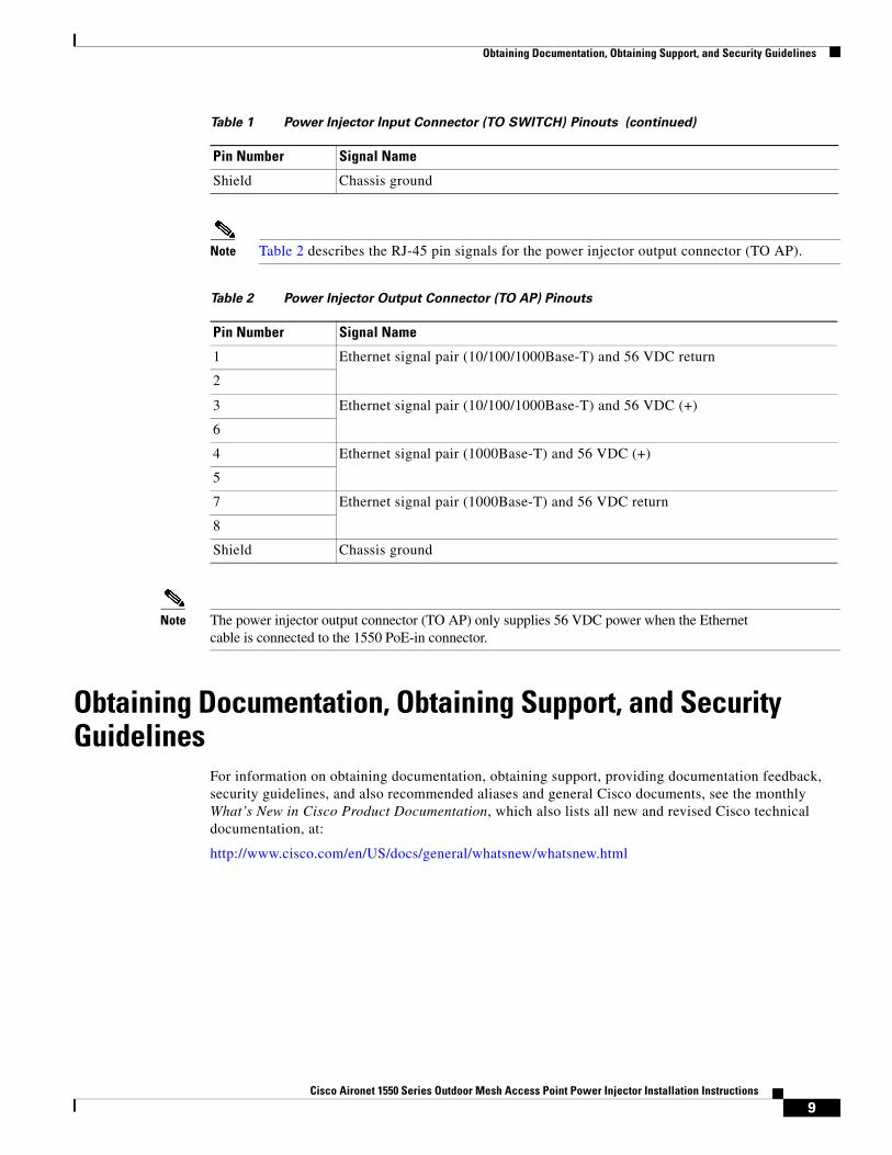
Note Table 2 describes the RJ-45 pin signals for the power injector output connector (TO AP).
Note The power injector output connector (TO AP) only supplies 56 VDC power when the Ethernet cable is connected to the 1550 PoE-in connector.
Obtaining Documentation, Obtaining Support, and Security Guidelines
For information on obtaining documentation, obtaining support, providing documentation feedback, security guidelines, and also recommended aliases and general Cisco documents, see the monthly What’s New in Cisco Product Documentation, which also lists all new and revised Cisco technical documentation, at:
http://www.cisco.com/en/US/docs/general/whatsnew/whatsnew.html
Shield Chassis ground
Table 1 Power Injector Input Connector (TO SWITCH) Pinouts (continued)
Pin Number Signal Name
Table 2 Power Injector Output Connector (TO AP) Pinouts
Pin Number Signal Name
1 Ethernet signal pair (10/100/1000Base-T) and 56 VDC return
2
3 Ethernet signal pair (10/100/1000Base-T) and 56 VDC (+)
6
4 Ethernet signal pair (1000Base-T) and 56 VDC (+)
5
7 Ethernet signal pair (1000Base-T) and 56 VDC return
8
Shield Chassis ground
9Cisco Aironet 1550 Series Outdoor Mesh Access Point Power Injector Installation Instructions
Obtaining Documentation, Obtaining Support, and Security Guidelines
©Cisco and the Cisco logo are trademarks or registered trademarks of Cisco and/or its affiliates in the U.S. and other countries. To view a list of Cisco trademarks, go to this URL: www.cisco.com/go/trademarks. Third-party trademarks mentioned are the property of their respective owners. The use of the word partner does not imply a partnership relationship between Cisco and any other company. (1110R)
10Cisco Aironet 1550 Series Outdoor Mesh Access Point Power Injector Installation Instructions