Gradient fiber electrospinning of layered scaffolds using controlled transitions in fiber diameter
14
Gradient fiber electrospinning of layered scaffolds using controlled transitions in fiber diameter Casey P. Grey a , Scott T. Newton b , Gary L. Bowlin a , Thomas W. Haas a , David G. Simpson b, * a Department of Biomedical Engineering, Virginia Commonwealth University, Richmond, VA 23298, USA b Department of Anatomy and Neurobiology, Virginia Commonwealth University, Richmond, VA 23298, USA article info Article history: Received 17 January 2013 Accepted 12 March 2013 Available online 18 April 2013 Keywords: Electrospinning PCL Delamination Tissue engineering scaffolds Materials testing Burst testing abstract We characterize layered, delamination resistant, tissue engineering scaffolds produced by gradient electrospinning using computational fluid dynamics, measurements of fiber diameter with respect to dynamic changes in polymer concentration, SEM analysis, and materials testing. Gradient electro- spinning delivers a continuously variable concentration of polymer to the electrospinning jet, resulting in scaffolds that exhibit controlled transitions in fiber diameter across the Z-axis. This makes it possible to produce scaffolds that exhibit very different fiber sizes and material properties on opposing surfaces while eliminating the boundary layers that lead to delamination failures. In materials testing bi-layered laminated electrospun scaffolds (layer 1 ¼ <250 nm, layer 2 ¼ 1000 nm diameter polycaprolactone fibers) exhibit ductile properties and undergo multiphasic failure. In contrast, scaffolds, produced by gradient electrospinning fabricated with fibers of this type on opposing surfaces fracture and fail as unified, and mechanically integrated, structures. Gradient electrospinning also eliminates the anisotropic strain properties observed in scaffolds composed of highly aligned fibers. In burst testing, scaffolds composed of aligned fibers produced using gradient electrospinning exhibit superior material properties with respect to scaffolds composed of random or aligned fibers produced from a single polymer con- centration or as bi-layered, laminated structures. Ó 2013 Elsevier Ltd. All rights reserved. 1. Introduction The extracellular matrix (ECM) and cellular elements of hollow organs and other select tissues, notably, blood vessels, cartilage, and skin, are arranged into layers. The structural and living elements of these layered tissues are mechanically integrated with one another in order to withstand the stresses and strains routinely encountered during normal physiological function. For example, the prototypical artery is classically described to have three distinct layers, each with unique material properties [1,2]; the tunica intima, tunica media, and the tunica adventitia. The actual structure and functional at- tributes of each layer are far more complex [3] and difficult to capture in a tissue engineered material. The innermost layer, the tunica intima, is composed of a single cellular layer of endothelium resting on, and separated from, the deeper structures by a basement membrane. An internal elastic lamina may be present. The tunica media contains varying layers of smooth muscle cells with an ECM rich in proteoglycans, reticular fibers, and fibrils of Type I collagen. The smooth muscle cells are organized in two principal patterns; the bulk of these fusiform cells are positioned in a radial fashion around the lumen of the vessel and a secondary population is distributed in a spiral pattern along the length of the artery. The tunica adventitia contains larger diameter fibers of collagen, elastic fibers, scattered fibroblasts, nerves, and lymphatics. While each layer of the prototypical blood vessel exhibits unique structural and material properties, each layer is also mechanically integrated with the adjacent layer, allowing the tissue to function as a unified structure. The transmission of mechanical stresses across the boundary layers that inherently exist where materials of different mechanical properties intersect is critical. Without true integration, mechanical stresses are concentrated at the interface of the layers, increasing the risk of delamination failure (separation of the layers at the boundary interface). Integration allows these mechanical stresses to be transmitted across the boundary and dissipated into the next layer of material. Arguably, one of the most important factors in the future success of tissue engineered mate- rials is the development of scaffolds designed to mimic the archi- tecture and function of the native target tissue [4,5]. While this is conceptually and theoretically possible, attempts to recapitulate the specific structural elements and functional properties present in an organ using tissue engineering has been largely unsuccessful. * Corresponding author. E-mail address: [email protected] (D.G. Simpson). Contents lists available at SciVerse ScienceDirect Biomaterials journal homepage: www.elsevier.com/locate/biomaterials 0142-9612/$ e see front matter Ó 2013 Elsevier Ltd. All rights reserved. http://dx.doi.org/10.1016/j.biomaterials.2013.03.033 Biomaterials 34 (2013) 4993e5006
-
Upload
independent -
Category
Documents
-
view
0 -
download
0
Transcript of Gradient fiber electrospinning of layered scaffolds using controlled transitions in fiber diameter

at SciVerse ScienceDirect
Biomaterials 34 (2013) 4993e5006
Contents lists available
Biomaterials
journal homepage: www.elsevier .com/locate/biomater ia ls
Gradient fiber electrospinning of layered scaffolds using controlledtransitions in fiber diameter
Casey P. Grey a, Scott T. Newton b, Gary L. Bowlin a, Thomas W. Haas a, David G. Simpson b,*
aDepartment of Biomedical Engineering, Virginia Commonwealth University, Richmond, VA 23298, USAbDepartment of Anatomy and Neurobiology, Virginia Commonwealth University, Richmond, VA 23298, USA
a r t i c l e i n f o
Article history:Received 17 January 2013Accepted 12 March 2013Available online 18 April 2013
Keywords:ElectrospinningPCLDelaminationTissue engineering scaffoldsMaterials testingBurst testing
* Corresponding author.E-mail address: [email protected] (D.G. Simpson
0142-9612/$ e see front matter � 2013 Elsevier Ltd.http://dx.doi.org/10.1016/j.biomaterials.2013.03.033
a b s t r a c t
We characterize layered, delamination resistant, tissue engineering scaffolds produced by gradientelectrospinning using computational fluid dynamics, measurements of fiber diameter with respect todynamic changes in polymer concentration, SEM analysis, and materials testing. Gradient electro-spinning delivers a continuously variable concentration of polymer to the electrospinning jet, resulting inscaffolds that exhibit controlled transitions in fiber diameter across the Z-axis. This makes it possible toproduce scaffolds that exhibit very different fiber sizes and material properties on opposing surfaceswhile eliminating the boundary layers that lead to delamination failures. In materials testing bi-layeredlaminated electrospun scaffolds (layer 1 ¼ <250 nm, layer 2 ¼ 1000 nm diameter polycaprolactonefibers) exhibit ductile properties and undergo multiphasic failure. In contrast, scaffolds, produced bygradient electrospinning fabricated with fibers of this type on opposing surfaces fracture and fail asunified, and mechanically integrated, structures. Gradient electrospinning also eliminates the anisotropicstrain properties observed in scaffolds composed of highly aligned fibers. In burst testing, scaffoldscomposed of aligned fibers produced using gradient electrospinning exhibit superior material propertieswith respect to scaffolds composed of random or aligned fibers produced from a single polymer con-centration or as bi-layered, laminated structures.
� 2013 Elsevier Ltd. All rights reserved.
1. Introduction
The extracellular matrix (ECM) and cellular elements of holloworgans and other select tissues, notably, blood vessels, cartilage, andskin, are arranged into layers. The structural and living elements ofthese layered tissues are mechanically integrated with one anotherin order towithstand the stresses and strains routinely encounteredduring normal physiological function. For example, the prototypicalartery is classically described to have three distinct layers, eachwithunique material properties [1,2]; the tunica intima, tunica media,and the tunica adventitia. The actual structure and functional at-tributes of each layer are far more complex [3] and difficult tocapture in a tissue engineered material. The innermost layer, thetunica intima, is composed of a single cellular layer of endotheliumresting on, and separated from, the deeper structures by a basementmembrane. An internal elastic lamina may be present. The tunicamedia contains varying layers of smooth muscle cells with an ECMrich in proteoglycans, reticular fibers, and fibrils of Type I collagen.The smooth muscle cells are organized in two principal patterns;
).
All rights reserved.
the bulk of these fusiform cells are positioned in a radial fashionaround the lumen of the vessel and a secondary population isdistributed in a spiral pattern along the length of the artery. Thetunica adventitia contains larger diameter fibers of collagen, elasticfibers, scattered fibroblasts, nerves, and lymphatics.
While each layer of the prototypical blood vessel exhibits uniquestructural and material properties, each layer is also mechanicallyintegrated with the adjacent layer, allowing the tissue to functionas a unified structure. The transmission of mechanical stressesacross the boundary layers that inherently exist where materials ofdifferent mechanical properties intersect is critical. Without trueintegration, mechanical stresses are concentrated at the interface ofthe layers, increasing the risk of delamination failure (separation ofthe layers at the boundary interface). Integration allows thesemechanical stresses to be transmitted across the boundary anddissipated into the next layer of material. Arguably, one of the mostimportant factors in the future success of tissue engineered mate-rials is the development of scaffolds designed to mimic the archi-tecture and function of the native target tissue [4,5]. While this isconceptually and theoretically possible, attempts to recapitulatethe specific structural elements and functional properties presentin an organ using tissue engineering has been largely unsuccessful.

C.P. Grey et al. / Biomaterials 34 (2013) 4993e50064994
Electrospinning has been, and continues to be, explored as aprocessing strategy for the production of physiologically relevanttissue engineering scaffolds [6e8]. This adaptable technology canselectively process a variety of native [9e11], synthetic [12,13], andblends of native and synthetic [14,15] polymers into nano-to-micron scale diameter fibers that mimic the dimensions of nativeECM constituents. First generation vascular constructs produced byelectrospinning were composed of uniform fibers that wereselected and/or engineered to withstand physiological mechanicalloads [16]. Second generation designs exhibit different fiber typesthat have been deposited into specific layers in order to moreclosely mimic the structure of the native vessel [17]. Electro-spinning makes it relatively easy to produce constructs with atunica intima-like layer composed of very small diameter fibersthat is overcoated with larger diameter fibers to form a compositetunica media/tunica adventitia [18]. The fine fibers of the innerlayer provide adhesion sites for cells along the luminal surfacewhile the larger diameter fibers are intended to lend mechanicalstability to the engineered construct. Unfortunately, this directapproach, and related methods designed to entangle fibers ofdifferent compositions [17,19], produce a laminated structure withboundary layers. From a structural standpoint this type of constructcan be fabricated to resemble the architecture of the native ECM.From a functional standpoint, when this simple type of construct issubjected to mechanical loading, stress is concentrated at theinterface of the layers and the device can be expected to undergomultiphasic delamination failure [18].
A central challenge in tissue engineering is to create scaffoldsthat mimic the mechanical and functional characteristics of thetarget tissue [5]. One clear strategy to reducing the risk of delam-ination in multi-layered constructs is to modulate the transitionalproperties of the boundary domains. To our knowledge the pro-duction of a continuous fiber gradient in an electrospun scaffold asa strategy to reduce the impact of the boundary layers that inher-ently exist in any composite material has not been examined withany great detail. Limited experimentation directed at developingfunctionally graded tissue-engineering scaffolds containing nano-particle gradients have been reported [20,21]. These studiesconcentrated on evaluating the distribution of the nano-particlesacross the Z-axis of the electrospun tissue engineering scaffoldwith respect to conditions that could be used to increase the overalltensile strength of the resulting constructs.
In the present study we describe and characterize the process ofgradient fiber electrospinning. This technique makes it possible toproduce layered electrospun scaffolds that exhibit a gradual andcontinuous transition in average fiber diameter across the Z-axis.These transitions reduce the concentration of stress that typicallyoccurs at the boundary of different fiber types. We prototypegradient electrospinning using two different scaffold designs. Thefirst prototype scaffold (designated “22-gauge”) has one facecomposed of electrospun polycaprolactone (PCL) fibers with anaverage cross sectional diameter of 0.17 � S.D. 0.09 mm. Averagefiber size increases across the Z-axis in this type of scaffold andreaches an average cross sectional diameter of 0.78 � S.D. 0.89 mmon the opposite face. The fibers of the second prototype scaffold(“18-gauge”) are similar and range from 0.24 � S.D. 0.12 mm on onesurface up to 0.89 � S.D. 0.96 mm on the other surface. The totaloverall average fiber diameter, as a population, that is present in the18-gauge scaffold is larger and it exhibits a steeper “fiber gradient”across the Z-axis than the 22-gauge prototype. These architecturalfeatures confer unique material properties to these constructs. Thecharacteristics of scaffolds produced by gradient fiber electro-spinning were evaluated against both pure fiber scaffolds (controls)and those produced as laminated structures using: computationalfluid dynamics (fluid modeling), output polymer concentration
with respect to time (experimental mixing characteristics), outputfiber diameter with respect to time (experimental electrospinningcharacteristics), mechanical testing (tensile/burst, overall scaffoldfailure properties), and SEM (scanning electron microscope) anal-ysis of scaffolds before, during, and after mechanical testing (failuremodes).
2. Materials and methods
2.1. Computational fluid dynamics (CFD)
All computer drawings andmeshes developed using Gambit (Version 2.4). Fluid-models were analyzed in Fluent (Version 12.0) using 1000 iterations or untilconvergence was achieved, graphical representations prepared in Tecplot. Gradientelectrospinning was modeled using a 3 mL plastic BD syringe (ID ¼ 0.876 cm) as areservoir. The intermediate disk contained a central port sized to the equivalent of a22-gauge (ID ¼ 0.413 mm) or an 18-gauge (ID ¼ 0.838 mm) needle segment. Thehigh concentration polycaprolactone (65,000 M.W.) solution (top reservoir) wasmodeled at 200 mg/mL with a viscosity of 1.11�107 kg/m*s and a density of 958 kg/m3; the low concentration PCL solution (bottom solution) was modeled at 100 mg/mL with a viscosity of 4.6 � 106 kg/m*s and a density of 951 kg/m3. Electrospinningoutlet was an 18-gauge needle. The model incorporated a mass flow rate of 8 mL/h.False colors represent the magnitude of fluid velocity, measured in mm/s.
2.2. Electrospinning
All reagents were obtained from Sigma unless noted. Polycaprolactone (PCL:65,000 M.W.) was suspended and electrospun from trifluoroethanol (TFE; 100 or200 mg/mL). Electrospinning syringes were capped with an 18-gauge blunt-tippedneedle and installed into a syringe pump (Fisher Scientific), solutions delivered at8 mL/h into a static electric field (18 kV, Spellmen). All spinning took place across a20 cm gap onto a grounded cylindrical metal target (length ¼ 11.75 cm,diameter ¼ 6.33 mm) designed to rotate and translate laterally (4 cm/s over a 12 cmdistance) to promote an even coating of polymer. Scaffolds were collected at either700 rpm (random) or 7000 rpm (aligned). Laminated scaffolds were produced bysequentially spinning 100mg/mL PCL onto the target, this layer was overcoated witha second, separate layer of fibers spun from 200 mg/mL PCL.
2.3. Gradient electrospinning
In conventional electrospinning fiber size is positively correlated withincreasing polymer concentration [13,22]. By engineering a polymer concentrationgradient within the electrospinning reservoir it is theoretically possible to deliver acontinuously variable gradient of polymer at the electrospinning jet, in turn,resulting in the production of a gradient of fiber sizes. Traditional methods haveattempted to achieve this by entangling different electrospinning jets [23] or mixingdifferent solutions at the orifice of the electrospinning needle(s), however, thesestrategies lead to inconsistent results, the partitioning of the different polymerstreams, and/or scaffolds composed of two interwoven fiber types (not a fibergradient). We used a single reservoir that contained two separate compartmentsinterconnected by a port designed to control the extent of mixing that takes placebetween the solutions at a position proximal to the distal electrospinning jet.
Two-chambered electrospinning reservoirs were prepared by placing 1.5 mL of100 mg/mL PCL into a 3 mL syringe (Fig. 2). The intermediate disk (“mixing port”) iscreated by piercing the rubber cap of a syringe plunger with an indwelling, 5 mmsegment of either a 22-gauge or an 18-gauge needle. This intermediate disk is thenpositioned on top of the 100 mg/mL PCL solution. Next the syringe is filled with1.5 mL of 200 mg/mL PCL. The plunger is then installed into the syringe. At the onsetof electrospinning, the mixing port remains stationary until the primary syringeplunger comes into contact with it, at which point it is driven down the length of thesyringe. By remaining stationary the mixing port allows the controlled mixing ofsolutions, thus creating the smooth gradient of polymer (and thus fibers). Engi-neering the mixing port to move in synchrony with the primary plunger results in ascaffold that appears, and behaves in materials testing, like a laminated structure(i.e. the moving intermediate port produces an abrupt change in polymer concen-tration and fiber diameter during spinning).
2.4. Instantaneous PCL concentration
Solutions were delivered at a rate of 8 mL/h into a weighing dish from theelectrospinning reservoirs in the absence of an electric field. Fixed volumes of thedispensed PCL solutions were collected at set intervals of time, the solvent wasallowed to evaporate, and the sample dry weight was determined and used toextrapolate the instantaneous PCL concentration. For example, if samples werecollected at 2-min intervals for 10minwith a flow rate of 8mL/h, 5 sampleswould becollected, each containing 0.267 mL of fluid. By dividing the PCL dry weight by0.267mL the instantaneous PCL concentration at each time point can be determined.

C.P. Grey et al. / Biomaterials 34 (2013) 4993e5006 4995
2.5. Fiber diameter analysis
Electrospun samples were collected for 2-min at 2-min intervals during gradientelectrospinning. A Zeiss EVO 50 Scanning Electron Microscope (SEM) was used toimage samples. Representative images were captured at 1500� at a resolution of1024 � 768. Images were overlaid with a uniform half-grid mask and only the fibersthat crossed the designated lines were measured. All images were calibrated andimported into ImageJ for fiber diameter analysis [13].
2.6. Tensile testing
AMTS Bionix Tensile Test System (50N load cell) was used formechanical testingat a strain rate of 10 mm/min. All scaffolds were prepared from a constant volume of3.5 mL. Scaffolds were soaked in ethanol (5 min), removed from the mandrel, driedovernight, cut lengthwise, and unrolled. “Dog bone” shaped samples were punchedfrom the scaffolds (ODC Tooling and Molding Sharp-Edge Die: 6.2 � 18.6 mm) alongthe axis of mandrel rotation (“parallel”) and 90� to the axis of rotation (“perpen-dicular”). A Mitutoyo Absolute caliper was used to determine sample thickness.
2.7. Burst testing
Burst strength testing was completed using a device designed in accordancewith Section 8.3.3.3 of ANSI/AAMI VP20: 1994 [17]. Scaffolds were soaked in ethanol(<5 min), removed from the mandrel, and dried overnight. Intact tubes, 2e3 cm inlength, were fitted over 1.5mmdiameter nipples attached to the device, and securedwith 2e0 silk suture. Air was introduced into the system (5e10 mmHg/s) until thetubes burst, at which point the peak pressure was recorded. We only considerapparent hoop stress to compare and contrast our constructs in burst testing(Equation (1)). We acknowledge that differences in resistance to axial deformationsurely exist between scaffolds, however, the extent of axial strain did not begin toapproach the limits of failure as determine by tensile testing therefore its contri-bution to scaffold failure was assumed to be minimal in this study.
Apparent hoop stress:
sq ¼ Prt
(1)
where P ¼ burst pressure, r ¼ radius of the construct and t ¼ the wall thickness.Average scaffold thickness in burst test assays: 100 Control e Not Aligned
(0.389 mm), 100 Control e Aligned (0.406 mm). 200 Control e Not Aligned
Fig. 1. Control conditions. Random electrospun scaffolds (700 RPM) produced with (A) 10produced with (C) 100 mg/mL PCL and (D) 200 mg/mL PCL. Bar ¼ 10 mm.
(0.414 mm), 200 Control e Aligned (0.373 mm). Laminated e Not Aligned(0.356 mm), Laminated e Aligned (0.381 mm). Integrated 22G e Not Aligned(0.373 mm), Integrated 22G e Aligned (0.356 mm), Integrated 18G e Not Aligned(0.335 mm), Integrated 18G e Aligned (0.203 mm).
2.8. Statistics
All data sets were analyzed in Sigma Plot and screened using ANOVA. TheHolm-Sidak method was used for pairwise comparisons. P values as provided.Graphical depictions represent � the standard error unless otherwise noted.
3. Results
3.1. Control conditions
Scaffolds produced from 100 mg/mL control PCL solutions werecomposed of fibers with an average cross sectional diameter of0.21 � S.D. 0.09 mm (Fig. 1A). These fibers were interspersed withbeads, indicating that we were spinning near the lower limits ofpolymer concentration necessary to produce fibers. A surprisingdegree of apparent fiber alignment could be achieved when thesescaffolds were collected at 7000 RPM (Fig. 1C). Fibers less thanabout 0.8e1.0 microns in diameter are typically difficult to align inconventional electrospinning systems [22], the beads present inour samples appear to add themomentum necessary to cause somedegree of fiber alignment. Scaffolds produced from the 200 mg/mLsolutions were composed of fibers with an average cross-sectionaldiameter of 1.02 � S.D. 0.90 mm (Fig. 1B). As expected, the fibers ofthese scaffolds exhibited a considerable degree of alignment whencollected at 7000 RPM (Fig. 1D).
3.2. CFD modeling
Our approach to producing a continuous and variable concen-tration gradient of polymer is outlined in Fig. 2. This CFD model
0 mg/mL PCL and (B) 200 mg/mL PCL and aligned electrospun scaffolds (7000 RPM)

Fig. 2. CFD. Fluid model simulations of gradient fiber electrospinning using a 22 or 18-gauge intermediate channel predicted that a substantial increase in fluid velocity (measuredin mm/s) occurs at the channel, around the channel, and at the syringe outlet with respect to the bulk solution. This gradient in fluid velocity can be expected to result in controlledmixing between the two fluids, mainly occurring in the vicinity of the intermediate channel. (A) Detail of 22 gauge intermediate channel (B) Complete 22 gauge system. (C) Detail of18 gauge intermediate channel (D) Complete 18 gauge system. (E). Detail of intermediate channel overlay with a difference filter where black represents shared pixel values, falsecolors indicate areas where the CFD model for fluid velocity diverges in the different port configurations. Extrapolating from these models suggests that a 22-gauge systemwill havehigher velocities and more mixing in domains subjacent to the port. (F) Gradient electrospinning syringe, arrow ¼ intermediate plunger with indwelling 18-gauge needle segmentas a mixing port. (G) Gradient electrospinning syringe, arrow ¼ detail of indwelling 18-gauge needle. (For interpretation of the references to colour in this figure legend, the reader isreferred to the web version of this article.)
C.P. Grey et al. / Biomaterials 34 (2013) 4993e50064996
depicts the magnitude of the theoretical fluid velocities (in mm/s)that result in our gradient fiber electrospinning system using eithera 22-gauge (Fig. 2A, B) or an 18-gauge mixing port (Fig. 2C, D). Thesimulations indicate that the fluid velocities in and around themixing ports are substantially elevated above that of the bulk so-lution, a condition that should result in varying degrees of polymermixing in these domains. While the models are similar, it should benoted that the fluid velocities do vary between the systems. Thiscan be demonstrated by overlaying the domains occupied by the 22and 18-gauge mixing ports and running a difference filter acrossthe images (Fig. 2E). The CFDmodel predicts that fluid velocities arehigher in the vicinity of the intermediate disk in the 22-gaugesystem with respect to the same domains in the 18-gauge system,this increased velocity should translate into more mixing and amore gradual concentration gradient in the 22-gauge system. If thisCFD model, overall, has validity several measurable characteristicsshould be detectable, including the formation of a concentrationgradient at the output needle of the electrospinning system as afunction of time, commensurate changes in fiber diameter as the
concentration gradient develops, and distinct scaffold mechanicalproperties compared to scaffolds produced with no gradient.
3.3. Instantaneous PCL concentration
To verify that a concentration gradient develops as predicted byCFD we collected PCL solutions as a function of time during a“simulated” (no electric field) electrospinning experiment. In theseexperiments the extrapolated PCL concentration gradient thatdeveloped with the 22-gauge port system (Fig. 3A) was moregradual (as judged by regression analysis for instantaneous poly-mer concentration vs. time, not shown) than the gradient devel-oped with the 18-gauge port system (Fig. 3B).
3.4. Fiber diameter analysis
The formation of a continuously variable polymer gradient atthe electrospinning jet as a function of time should result in theproduction of fibers that vary in cross-sectional diameter as a

Fig. 3. PCL and fiber gradients as a function of time. (A) Concentration gradient produced by 22-gauge port system ranged from 100 mg to a maximal value of 165 mg PCL/mL TFE.(B) Concentration gradient produced by 18-gauge port system ranged from 100 mg to maximal value of 170 mg PCL/mL TFE. (C) Fibers produced by 22-gauge port were 0.17 � S.D.0.09 mm at the onset and 0.78 � S.D. 0.89 mm at the conclusion. At 2, 4 and 6 min: 22-gauge fibers ¼ 100 mg fibers. From 8 to 16 min: 100 mg fibers < 22-gauge fibers < 200 mgfibers. At 18e20 min: 22-gauge fibers ¼ 200 mg fibers. At 22 min: 200 mg fibers > 22-gauge fibers. Fibers produced at 8 min < fibers at 10e16 min (all P < 0.05). (D) Fibers producedby 18-gauge mixing port ranged from 0.24 � S.D. 0.12 mm to 0.89 � S.D. 0.96 mm at the end of the spinning interval. At 2 and 4 min: 22-gauge fibers ¼ 100 mg fibers. By 6 min:100 mg fibers < 18-gauge fibers < 200 mg fibers. From 10 to 16 min: 18-gauge ¼ 200 mg fibers, at 18 and 20 min 200 mg fibers > 18-gauge fibers, at 22 min 18-gaugefibers ¼ 200 mg fibers. Fibers produced at 6 min < fibers at 8,10, 12, 16, 18 min, fibers produced at 8 min < fibers at 10, 12, 14, 16 and 18 min (all P < 0.05). Error bars in Cand D denote 1 S.D. in the positive direction.
C.P. Grey et al. / Biomaterials 34 (2013) 4993e5006 4997
function of the electrospinning interval. In experiments to test thishypothesis the average fiber diameter produced with either portconfiguration matched that observed in the 100 mg/mL controlsolutions during the onset of spinning, subsequently, average fiberdiameter increased as a function of run time. In the 22-gauge sys-tem, the first three “fiber” fractions collected at 2, 4 and 6 minyielded fibers that were size matched to the fibers present inscaffolds spun from 100 mg/mL control solutions. From 8 min to16 min the fibers produced by the 22-gauge system were inter-mediate, and different, from the 100 mg and 200 mg controls(P < 0.05). After 18 min the fibers produced with this setupapproached and overlapped the range of fiber diameters present in
the 200mg/mL control scaffold. Overall, the scaffold produced fromthe 22-gauge system had fibers that were 0.17 � S.D. 0.09 mm onone face that ranged up to 0.78 � S.D. 0.89 mm on the other face(Figs. 3C and 4).
The 18-gauge mixing system exhibited a steeper concentrationgradient that was correlated with a steeper “fiber” gradient thanthe fiber gradient producedwith the 22-gauge system. The first two“fiber” fractions produced using the 18-gauge mixing port andcollected at 2 and 4 min yielded fibers that were size matched tothe fibers produced from the 100mg/mL control solutions. Over theinterval of 6 mine8 min the 18-gauge system produced fibers thatwere intermediate, and different from, the 100 mg and 200 mg

Fig. 4. SEM analysis of 22-gauge mixing port gradient electrospinning. (A) 100 mg/mL control fibers (B) 200 mg/mL control fibers. (C) Fibers produced from a 22-gauge mixingsystem after 2 min. (DeL) Fibers produced at each subsequent 2-min time interval. Note that with respect to scaffolds produced with the 18-gauge port (Fig. 5) the increasednumber “fiber fractions” that display small diameter fibers and beads (e.g. CeG). Bar ¼ 10 mm.
C.P. Grey et al. / Biomaterials 34 (2013) 4993e50064998
controls (P < 0.05). By 10 min fibers produced from the 18-gaugemixing port approximated the fibers present in the 200 mg/mLcontrol scaffolds. Overall, the 18-gauge port system resulted in theproduction of a scaffold composed of fibers that ranged from0.24 � S.D. 0.12 mm on one face to 0.89 � S.D. 0.96 mm on the otherface (Figs. 3D and 5 and for cross sectional images Fig. 7A random,Fig. 7B aligned).
In summary, each port system produced a similar population offibers; however, the 18-gauge system produced a population thatwas skewed towards the production of larger diameters at earliertime points in the electrospinning interval. The average crosssectional diameter for all fibers in all fractions produced by the22-gauge systemwas less (P< 0.001) than the overall cross sectionaldiameter for all fibers in all fractions produced by the 18-gaugesystem (22-gauge fibers: 0.56 � S.D. 0.73 mm, median diameter of0.29 mm vs. 18-gauge: 0.65 � S.D. 0.77 mm, median diameter of0.35 mm). Consistentwith this data, the slope of the regression curve(average fiber diameter vs. electrospinning interval) generated for
the 18-gauge system was steeper and reached a maximal fiberdiameter value sooner than the 22-gauge system (not shown).
3.5. Tensile testing: random scaffolds
Fabricating a scaffold composed of fibers that vary continuouslyin cross-sectional diameter across the Z-axis of the construct shouldbe manifest in the guise of unique material properties and me-chanical failure characteristics. Much like our gradient scaffolds, abi-layered laminated scaffold that is sequentially electrospun froma 100 mg/mL PCL solution followed by a 200 mg/mL PCL solutionexhibits small diameter fibers on one face and large diameter fiberson the other face. This type of bi-layered laminate, composed offiber layers with very different material properties, will undergo adelamination failure. Stress is concentrated at the interface of thetwo fiber layers and they separate from one another at theboundary prior to complete scaffold failure. The production of fi-bers that are continuously varied in cross-sectional diameter across
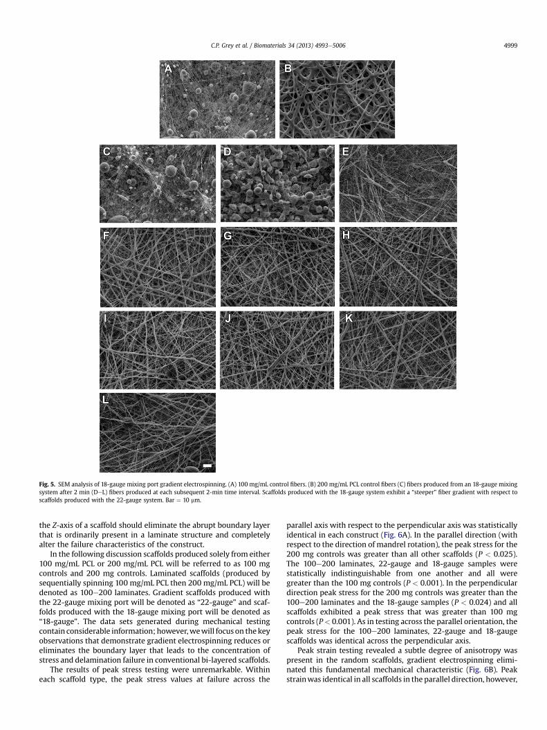
Fig. 5. SEM analysis of 18-gauge mixing port gradient electrospinning. (A) 100 mg/mL control fibers. (B) 200 mg/mL PCL control fibers (C) fibers produced from an 18-gauge mixingsystem after 2 min (DeL) fibers produced at each subsequent 2-min time interval. Scaffolds produced with the 18-gauge system exhibit a “steeper” fiber gradient with respect toscaffolds produced with the 22-gauge system. Bar ¼ 10 mm.
C.P. Grey et al. / Biomaterials 34 (2013) 4993e5006 4999
the Z-axis of a scaffold should eliminate the abrupt boundary layerthat is ordinarily present in a laminate structure and completelyalter the failure characteristics of the construct.
In the following discussion scaffolds produced solely from either100 mg/mL PCL or 200 mg/mL PCL will be referred to as 100 mgcontrols and 200 mg controls. Laminated scaffolds (produced bysequentially spinning 100 mg/mL PCL then 200 mg/mL PCL) will bedenoted as 100e200 laminates. Gradient scaffolds produced withthe 22-gauge mixing port will be denoted as “22-gauge” and scaf-folds produced with the 18-gauge mixing port will be denoted as“18-gauge”. The data sets generated during mechanical testingcontain considerable information; however,wewill focus on thekeyobservations that demonstrate gradient electrospinning reduces oreliminates the boundary layer that leads to the concentration ofstress and delamination failure in conventional bi-layered scaffolds.
The results of peak stress testing were unremarkable. Withineach scaffold type, the peak stress values at failure across the
parallel axis with respect to the perpendicular axis was statisticallyidentical in each construct (Fig. 6A). In the parallel direction (withrespect to the direction of mandrel rotation), the peak stress for the200 mg controls was greater than all other scaffolds (P < 0.025).The 100e200 laminates, 22-gauge and 18-gauge samples werestatistically indistinguishable from one another and all weregreater than the 100 mg controls (P < 0.001). In the perpendiculardirection peak stress for the 200 mg controls was greater than the100e200 laminates and the 18-gauge samples (P < 0.024) and allscaffolds exhibited a peak stress that was greater than 100 mgcontrols (P< 0.001). As in testing across the parallel orientation, thepeak stress for the 100e200 laminates, 22-gauge and 18-gaugescaffolds was identical across the perpendicular axis.
Peak strain testing revealed a subtle degree of anisotropy waspresent in the random scaffolds, gradient electrospinning elimi-nated this fundamental mechanical characteristic (Fig. 6B). Peakstrainwas identical in all scaffolds in the parallel direction, however,

Fig. 6. Materials testing: Random scaffolds. (A) Peak stress across parallel axis ¼ peak stress in the perpendicular axis within each scaffold type. Parallel direction only: Peak stress200 mg controls > all scaffolds (*P < 0.025), perpendicular direction only: 200 mg controls > 100 mg controls, 100e200 laminates and 18-gauge scaffolds (**P < 0.024). (B) Peakstrain perpendicular direction > parallel direction in 200 mg scaffolds, 100e200 scaffolds and 22-gauge scaffolds (**P < 0.001). Parallel ¼ perpendicular axis in 100 mg controls and18-gauge scaffolds. (C) Stressestrain curves captured in parallel direction. (D) Stressestrain curves in perpendicular direction. Note the poorly defined peak stress, characterized by abroad plateau, and increased strain after peak stress present in 100e200 laminates, this pattern is consistent with delamination and is absent in the 22 and 18-gauge scaffolds.
C.P. Grey et al. / Biomaterials 34 (2013) 4993e50065000
peak strainwashigher in the perpendiculardirectionwith respect tothe parallel direction in the 200mg controls, the 100e200 laminatesand the 22-gauge scaffolds (P< 0.001). Of note, the 100mg controlsand the 18-gauge scaffolds did not exhibit anisotropy in this analysisand were statistically indistinguishable from one another. An ex-amination of the stressestrain curves provides clear evidence thatscaffolds produced by gradient electrospinning have materialproperties that are fundamentally different from the 100e200laminated scaffolds.
Stressestrain curves captured in the parallel direction for the200 mg controls, 22 and 18-gauge scaffolds exhibited a linear func-tion up to well defined peak stress value, the scaffolds then under-went fracture and complete failure (Fig. 6C). The initial stages of thestressestrain function in the 100e200 laminated scaffolds approxi-mated that observed in these scaffolds. However, and in clearcontrast, the stressestrain function of the 100e200 laminated scaf-folds exhibited a broad plateau characteristic of a delamination fail-ure. When tested in the perpendicular direction a more prolonged
interval of failurewasevident in the200mgcontrols (reflectiveof themodest anisotropydetected in tensile testing: Fig. 6B). This interval offailure was greatly exaggerated in the 100e200 laminated scaffolds(Fig. 6D) and is consistent with a delamination mode of failure.Gradient electrospinning completely eliminated the prolonged in-terval of failure observed in the 100e200 laminates and resulted inscaffolds that exhibited a well defined peak stress value and little orno residual strain, regardless of the direction of testing.
3.6. SEM: random scaffolds subjected to conventional tensile testing
SEM analysis confirms that the 100 mg layer of the 100e200laminated scaffolds initially fails during tensile testing, leaving the200 mg layer as the load-bearing element (Fig. 7C and D). As peakstress is approached in random scaffolds the fibers adjacent to thefracture zone begin to reorient and align along the axis of strain[24]. In 100e200 laminates this process is associated with thedisplacement, fragmentation and separation of the 100 mg layer

Fig. 7. SEM analysis of random scaffold failure characteristics. (A) Cross section through an untested 18-gauge random scaffold. Layer composed of larger diameter fibers on the topsurface (***) transitions into a heavily beaded dense layer of small fibers (*) at bottom of image. (B) Tangential section through an untested 18-gauge aligned scaffold. Top layer (*) inthis example is composed of beads interspersed with small diameter fibers that transition into larger diameter fibers (***). Double arrow depicts axis of alignment. (C & D) Fracturezone of random 100e200 laminate scaffold after testing. The 100 mg layer (*) is fragmented and displaced away from the surface of the underlying 200 mg layer (arrows denoteareas where continuity of the layers is lost). Note that fibers adjacent to the fracture zone in the underlying 200 mg layer align (D) as strain is applied to the construct. (E & F) Failureof 18-gauge scaffold. The 100 mg fiber (*) layer is continuous across the surface of the 200 mg (***) layer up to the fracture zone. Bar A ¼ 100 mm, B ¼ 20 mm, C, D, E and F ¼ 200 mm.
C.P. Grey et al. / Biomaterials 34 (2013) 4993e5006 5001
away from the intact, and now aligned fibers remaining in theunderlying 200 mg layer. In contrast, 22 and 18-gauge scaffoldsexhibit two distinct faces, each with a continuous layer of fibers upto the fracture zone (Fig. 7F).
3.7. Tensile testing: aligned scaffolds
To further explore the gradient technique we next preparedscaffolds composed of aligned fibers. This type of scaffold ordinarily
sustains high stress and low strain in the parallel direction (alongthe axis of fiber alignment), and low stress and high strain in theperpendicular direction [25]. In materials testing the peak stress inaligned scaffolds fabricated as 200mg controls, 100e200 laminates,22-gauge, and 18-gauge scaffolds was substantially higher in theparallel direction with respect to the perpendicular direction(P < 0.001: Fig. 8A). For these aligned samples, peak stress in theparallel direction was also 2e3 times higher than that observedalong this same orientation in the random scaffolds. Across the

Fig. 8. Materials testing: aligned scaffolds. (A) Peak stress across the parallel axis > peak stress in perpendicular axis for 200 mg controls, 100e200 laminates, 22-gauge and 18-gauge scaffolds (**P < 0.001). Parallel direction only: peak stress 200 mg controls > all scaffolds (P < 0.001); 100e200 mg ¼ 22-gauge ¼ 18-gauge samples > 100 mg controls(***P < 0.001). No differences across treatments in perpendicular direction. (B) Peak strain in perpendicular direction > parallel direction in 200 mg controls and 100e200 laminates(**P < 0.001). This anisotropy was not present in 100 mg controls, 22-gauge or 18-gauge scaffolds. Perpendicular direction only: peak strain for 200 mg scaffolds ¼ 100e200laminates > 100 mg, 22 and 18-gauge scaffolds (***P < 0.001). Parallel direction only, no differences across treatment groups was detected. (C) Stressestrain curves captured inparallel direction. (D) Stressestrain curves in perpendicular direction. Stressestrain curves for 22 and 18-gauge scaffolds are similar, regardless of orientation, and each exhibits awell defined peak stress and very little residual strain after the peak stress is reached. Stressestrain curves for 100e200 mg laminates exhibited distinctive, elongated plateaus.
C.P. Grey et al. / Biomaterials 34 (2013) 4993e50065002
aligned samples, peak stress in the parallel direction for the 200 mgcontrols was greater than all other scaffolds (P < 0.001); the 100e200 laminates, 22-gauge and 18-gauge samples were statisticallyidentical and all three were greater than the 100 mg controls(P < 0.001). In the perpendicular direction, peak stress for allsamples also was statistically identical (and approximately 50% ofthat observed in random200mg,100e200 laminates, 22-gauge and18-gauge scaffolds tested along this same axis). Taken together,these results confirm the aligned nature of these constructs.
In strain testing, and as expected, the peak strain in the 200 mgcontrols and the 100e200 laminates was similar and both werehigher in the perpendicular direction with respect to the paralleldirection (P < 0.001). These anisotropic strain properties werecompletely eliminated in aligned scaffolds produced by gradientelectrospinning. Peak strain in the 22 and 18-gauge aligned scaf-folds was statistically identical in the parallel and perpendiculardirections. In addition to these results, the 100 mg aligned scaffoldsdid not exhibit anisotropy in the analysis of peak stress or peakstrain, it seems likely that the beads present in these constructsserve to reduce anisotropic behavior (SEM reveals that fibers are
entangled on the surface of the beads, Fig. 1A). These fibers appearto impart this characteristic on the 22 and 18-gauge scaffolds. Thisstriking effect can be observed in the stressestrain curves.
The function of the stressestrain curves in the parallel directionfor the aligned 200 mg control scaffolds was similar to thatobserved in the random 200mg control scaffolds. The stressestrainfunction for the aligned scaffolds exhibited a linear domain leadingup to a well-defined peak stress followed by almost immediatescaffold failure (Fig. 8C). As expected, the stressestrain function forthe 200 mg aligned scaffolds was flatter and more elongated whentested along the perpendicular axis (i.e. elongation takes place atvery low levels of stress, Fig. 8D). The initial portion of the stressestrain function for the 100e200 mg laminates was similar to the200 mg controls and the 22 and 18-gauge scaffolds, however, oncepeak stress was achieved in these samples there was a dip in stresscharacterized by one or more plateaus, indicative of sequentialfailures in the laminated scaffolds (Fig. 8C). A similar pattern wasobserved in the perpendicular direction (Fig. 8D). This prolongedinterval of failure was absent in the 22 and 18-gauge scaffolds.Regardless of orientation, the stressestrain curves for these

C.P. Grey et al. / Biomaterials 34 (2013) 4993e5006 5003
gradient scaffolds exhibited a linear function that increasedabruptly to awell defined peak stress followed by complete scaffoldfailure with little or no residual strain.
3.8. SEM: aligned scaffolds subjected to conventional tensile testing
As noted for random scaffolds, the 100 mg layer of aligned 100e200 laminated scaffolds is separated and displaced away from theunderlying 200 mg layer during tensile testing (Fig. 9AeD). Inaligned 100e200 laminated scaffolds that have been tested in theparallel direction (along the fiber axis) the fibers of the 100 mglayer are pulled away from the 200 mg layer, often as a completeand intact sheet. Testing the 100e200 laminates in the perpen-dicular direction also results in the delamination of the 100 mglayer. Simultaneously, the aligned fibers of the underlying 200 mglayer undergo a degree of separation from one another and becomepartially re-oriented along the axis of testing. Scaffolds producedwith the 22 or 18-gauge mixing ports exhibit two distinct surfacesat the fracture zones. Once face composed of small diameter fibersinterspersed with beads and one composed of larger diameter, andhighly aligned larger diameter fibers.
3.9. Burst testing
Cylindrical constructs targeted to the reconstruction of holloworgans are subject to complex mechanical forces along multipledirections. Burst testing represents a critical metric of assessmentfor these structures. In random scaffolds (collected at 700 RPM) theapparent hoop stress at failure was similar in all samples and nostatistical differences were detected across the treatment groups(Fig. 10). Inducing fiber alignment in the cylindrical constructssubstantially altered the material properties of the scaffolds.Apparent hoop stress in the aligned 200 mg controls, 100e200laminates, 22-gauge and 18-gauge scaffolds was greater than thematched random counterparts (P < 0.002). The 18-gauge alignedgradient scaffolds exhibited a higher apparent hoop stress than allother scaffolds (P < 0.02).
3.10. SEM: scaffolds subjected to burst testing
SEM analysis provides clear evidence that scaffolds producedwith an 18-gauge mixing port and subjected to burst testing haveunique structural properties (Fig. 10). The catastrophic failure oflaminated scaffolds during burst testing results in the nearlycomplete obliteration of the 100 mg fiber layer. The destruction isso complete that it is difficult to find domains on the remainingelements of the 200 mg layer that contain evidence of these fibers.Only small and scattered domains of the 100 mg fiber layer remainin these constructs. In contrast, the scaffolds fabricated using the18-gauge mixing port exhibited two distinct faces after failure; oneface was composed of a continuous layer of large diameter fibers.The other face was composed of interconnected domains of the100 mg fibers. This layer was clearly stretched and damaged duringburst testing, however it remained attached to the underlying fi-bers of the 200 mg layer.
4. Discussion
The ECM and cellular elements of many tissue and organ sys-tems are distributed into layers that vary in size, identity, degree ofanisotropy, and intrinsic material properties. Such complex archi-tectural patterns serve to modulate the physical properties of thetissue and provide phenotypic cues to the resident cells [26]. Withthe development and continuing maturation of the regenerativemedicine discipline it has become increasingly clear that producing
tissue-engineering scaffolds which can truly mimic the structureand function of the native extracellular matrix represents adaunting task. Conventional electrospinning systems can superfi-cially replicate many aspects of the native extracellular matrix withrespect to fiber size and composition. Composite scaffolds caneasily be produced as laminated structures using basic techniques.For several reasons these layered structures are largely unsuitableas tissue engineering scaffolds. First, and foremost, layered elec-trospun scaffolds do not function as unified structures; they lackthe transitional boundaries that serve to effectively transfer me-chanical stresses between layers in native tissues. This leads to theconcentration of stress at the boundary layer and subsequentdelamination. Second, and unlike the native extracellular matrix,the fibers of electrospun scaffolds are deposited almost exclusivelyin the X and Y-planes with virtually no fibers oriented and/orentangled with one another across the Z-direction (perpendicularto the X and Y-plane). Finally, electrospun scaffolds are composed ofdistinct fibers that lack the accessory proteins that serve to bridgebetween and form crosslinks across the adjacent fibers of nativetissues. To some extent solvent and melt-welding [27], the intro-duction of physical crosslinks, or the use of external fixtures can beused to stabilize laminated tissue-engineering scaffolds, usually atthe expense of overall porosity [28], bio-compatibility, and/orphysiological performance [29]. While delamination failures can beeliminated by any number of engineering solutions, the challenge isto create a structure that mimics the mechanical and functionalcharacteristics of a biological tissue [5].
4.1. Polymer mixing properties
The polymer mixing properties in gradient fiber electrospinningare largelymediated by an interaction between themixing port andbulk solution properties. For example, CFD analysis indicates thatvarying the diameter of the intermediate channel in the mixingport, even a small amount, yields different fluid mixing propertiesin the system. Additional experimental conditions that might beexplored in this model that can be expected to alter the mixingdynamics include such variables as port geometry, solution tem-perature, solvent identity/solvent compatibility (resistance tomixing especially if using different solvents in the system), electricpotential, and solution conductivity. While a model that includesall of these variables would be complex to a fault, we believethat our simplified model encompassing only port diameter, portlength, solution viscosity, plunger velocity, and reservoir orienta-tion (e.g. vertical vs. horizontal electrospinning) is adequatelyrepresentative, and experimentally feasible. Changes in the fluidmixing ultimately affect the characteristics of polymer outflow fromthe devicewhich leads to differences in scaffold properties. While itremains to be fully explored, the fluidmixing differences seen in themodel may explain why the scaffolds produced with the 18-gaugemixing system appeared to outperform the scaffolds producedwith the 22-gauge port in some materials testing experiments.
4.2. Materials testing
In tensile testing, the 100e200 laminated scaffolds approxi-mated two individual scaffolds tested in parallel and, when theywere intact, these constructs resisted stress very much like the200 mg control scaffolds and scaffolds produced using the tworeservoir gradient. The material properties of the 100e200 lami-nated scaffolds markedly diverged from the other constructs oncethe 100 mg fiber layer failed, which resulted in a noticeabledecrease in the slope of the stressestrain curve, but not completemechanical scaffold failure. This change in slope occurs because theload is carried exclusively by the 200 mg layer which continues to

Fig. 9. SEM analysis of aligned scaffold failure characteristics. (A) Delamination of the 100 mg layer from the 200 mg layer adjacent to the fracture zone in 100e200 laminatescaffold tested in the parallel direction. (B) Scaffold from A: detail of delamination zone. (C) A 100e200 mg laminate tested in the perpendicular direction. (D) Scaffold from C: detailof delamination. Arrows indicate partial reorientation of fibers away from the perpendicular axis. (E) Fracture zone of aligned 18-gauge scaffold tested in the parallel direction. Notethe nearly unified nature of the fracture, arrows. Inset is low magnification image of entire fracture zone. For all images: *100 mg layer; ***200 mg layer. Long doublearrowhead ¼ direction of strain. Small double arrowheads (D and E) indicates orientation of fibers prior to testing. Arrows in E denote fracture zone. Bar in A ¼ 200, C ¼ 500, B, D,E ¼ 100 mm.
C.P. Grey et al. / Biomaterials 34 (2013) 4993e50065004
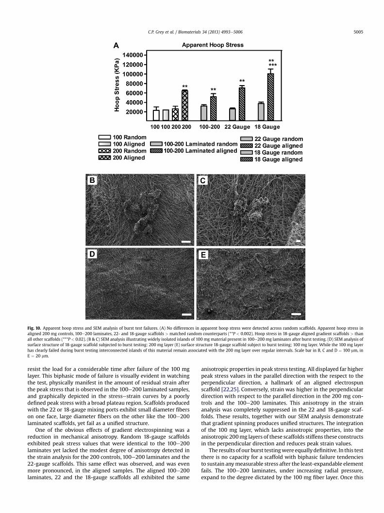
Fig. 10. Apparent hoop stress and SEM analysis of burst test failures. (A) No differences in apparent hoop stress were detected across random scaffolds. Apparent hoop stress inaligned 200 mg controls, 100e200 laminates, 22- and 18-gauge scaffolds > matched random counterparts (**P < 0.002). Hoop stress in 18-gauge aligned gradient scaffolds > thanall other scaffolds (***P < 0.02). (B & C) SEM analysis illustrating widely isolated islands of 100 mg material present in 100e200 mg laminates after burst testing. (D) SEM analysis ofsurface structure of 18-gauge scaffold subjected to burst testing: 200 mg layer (E) surface structure 18-gauge scaffold subject to burst testing; 100 mg layer. While the 100 mg layerhas clearly failed during burst testing interconnected islands of this material remain associated with the 200 mg layer over regular intervals. Scale bar in B, C and D ¼ 100 mm, inE ¼ 20 mm.
C.P. Grey et al. / Biomaterials 34 (2013) 4993e5006 5005
resist the load for a considerable time after failure of the 100 mglayer. This biphasic mode of failure is visually evident in watchingthe test, physically manifest in the amount of residual strain afterthe peak stress that is observed in the 100e200 laminated samples,and graphically depicted in the stressestrain curves by a poorlydefined peak stress with a broad plateau region. Scaffolds producedwith the 22 or 18-gauge mixing ports exhibit small diameter fiberson one face, large diameter fibers on the other like the 100e200laminated scaffolds, yet fail as a unified structure.
One of the obvious effects of gradient electrospinning was areduction in mechanical anisotropy. Random 18-gauge scaffoldsexhibited peak stress values that were identical to the 100e200laminates yet lacked the modest degree of anisotropy detected inthe strain analysis for the 200 controls, 100e200 laminates and the22-gauge scaffolds. This same effect was observed, and was evenmore pronounced, in the aligned samples. The aligned 100e200laminates, 22 and the 18-gauge scaffolds all exhibited the same
anisotropic properties in peak stress testing. All displayed far higherpeak stress values in the parallel direction with the respect to theperpendicular direction, a hallmark of an aligned electrospunscaffold [22,25]. Conversely, strain was higher in the perpendiculardirection with respect to the parallel direction in the 200 mg con-trols and the 100e200 laminates. This anisotropy in the strainanalysis was completely suppressed in the 22 and 18-gauge scaf-folds. These results, together with our SEM analysis demonstratethat gradient spinning produces unified structures. The integrationof the 100 mg layer, which lacks anisotropic properties, into theanisotropic 200mg layers of these scaffolds stiffens these constructsin the perpendicular direction and reduces peak strain values.
The results of our burst testingwere equallydefinitive. In this testthere is no capacity for a scaffold with biphasic failure tendenciesto sustain anymeasurable stress after the least-expandable elementfails. The 100e200 laminates, under increasing radial pressure,expand to the degree dictated by the 100 mg fiber layer. Once this

C.P. Grey et al. / Biomaterials 34 (2013) 4993e50065006
fiber layer fails, the 200 mg layer undergoes immediate and cata-strophic failure. This rapid successive failure takes place because thescaffold initially resists a large amount of stress, however, the100 mg layer fails at a far lower strain level than the 200 mg layer.Once the 100 mg layer fails the remaining scaffold is comparativelyless thick than the original scaffold and, as such, unable towithstandthe forces imparted on it by the burst test. Ultrastructural exami-nation of the laminated scaffolds near the location of failure afterburst testing revealed that the 100 mg layer is almost completelyobliterated during this catastrophic delamination failure. Only smalland extremely isolated islands of 100 mg layer were found stillattached to the 200 mg layer. In contrast, scaffolds produced bygradient electrospinning were mechanically integrated, at failurethese scaffolds exhibited a remnants of the 100 mg fibers at regularintervals on one face and 200mg fibers on the other face after bursttesting.
5. Conclusions
Gradient electrospinning makes it possible to produce scaffoldswith two distinctly different surfaces, one composed of smalldiameter fibers of PCL and one composed of larger diameter fibers ofPCL. Average fiber diameter varied continuously across the Z-axis ofthese structures, resulting in a scaffold with unique material prop-erties that failed as a unified structure. Gradient electrospinningmayprovide an avenue to developing complex composite structurestargeted to replace blood vessels, other hollow organs, cartilage,cardiac valves, and skin. At present we are exploring how CFD can beused to predict the appropriate starting conditions as we begin touse gradient electrospinning to combine different types of polymers.Of particular interest in our laboratories is to determine if we canproduce composites of native proteins that transition into blends ofnative proteins and synthetic polymers. We are also examining howthese unique composite structures and the resulting mechanicalgradients can be used to promote physiological communication and/or the migration of cells into electrospun scaffolds.
Acknowledgments
Scanning electron microscopy was conducted at the VCU,Department of Neurobiology and Anatomy Microscopy Facility,supported with funding from NIH-NCRR shared instrumentationGrant (1S10RR022495) and, in part, NIH-NINDS Center Core Grant(5P30NS047463). The authors would also like to thank Dr. WorthLongest (VCU, Department of Mechanical Engineering) whogenerously provided resources and advice for the development ofthe CFD model. US and International Patents Pending.
References
[1] Holzapfel GA, Gasser TC, Ogden RW. A new constitutive framework for arterialwall mechanics and a comparative study of material models. J Elast 2000;61(1e3):1e48.
[2] Holzapfel GA. Determination of material models for arterial walls from uniaxialextension tests and histological structure. J Theor Biol 2006;238(2):290e302.
[3] O’Connell MK, Murthy S, Phan S, Ziu C, Buchanan J, Spilker R, et al. Thethree-dimensional micro- and nanostructure of the aortic medial lamellar unitmeasured using 3D confocal and electron microscopy imaging. Matrix Biol2008;27(3):171e81.
[4] Simpson DG, Bowlin GL. Tissue-engineering scaffolds: can we re-engineermother nature? Expert Rev Med Devices 2006;3(1):9e15.
[5] Leong KF, Chua CK, Sudarmadji N, Yeong WY. Engineering functionally gradedtissue engineering scaffolds. J Mech Behav Biomed Mater 2008 4;1(2):140e52.
[6] Simpson DG. Dermal templates and the wound-healing paradigm: thepromise of tissue regeneration. Expert Rev Med Devices 2006;3(1):471e84.
[7] Madurantakam PA, Cost CP, Simpson DG, Bowlin GL. Science of nanofibrousscaffold fabrication: strategies for next generation tissue-engineeringscaffolds. Nanomedicine 2009;4(2):193e206.
[8] Ayres CE, Jha BS, Sell SA, Bowlin GL, Simpson DG. Nanotechnology in thedesign of soft tissue scaffolds: innovations in structure and function. WileyInterdiscip Rev Nanomed Nanobiotechnol 2010;1:20e34.
[9] Matthews JA, Wnek GE, Simpson DG, Bowlin GL. Electrospinning of collagennanofibers. Biomacromolecules 2002;3(2):232e8.
[10] McManus M, Boland ED, Sell SA, Bowen W, Koo H, Simpson DG, et al. Elec-trospun nanofibre fibrinogen for urinary tract tissue reconstruction. BiomedMater 2007;2(4):257e62.
[11] Jha BS, Ayres CE, Bowman JR, Telemeco TA, Sell SA, Bowlin GL, et al. Elec-trospun collagen: a tissue engineering scaffold with unique functional prop-erties in a wide variety of applications. J Nanomater 2011. http://dx.doi.org/10.1155/2011/348268.
[12] Boland ED, Coleman BD, Barnes CP, Simpson DG, Wnek GE, Bowlin GL. Elec-trospinning polydioxanone for biomedical applications. Acta Biomater2005;1(1):115e23.
[13] Jha BS, Colello RJ, Bowman JR, Sell SA, Lee KD, Bigbee JW, et al. Two pole airgap electrospinning: fabrication of highly aligned, three-dimensional scaffoldsfor nerve reconstruction. Acta Biomater 2011;7(1):203e15.
[14] Telemeco TA, Ayres CE, Bowlin GL, Wnek GE, Boland ED, Cohen N, et al.Regulation of cellular infiltration into tissue engineering scaffolds composedof submicron diameter fibrils produced by electrospinning. Acta Biomater2005;1(4):377e85.
[15] Sell SA, McClure MJ, Barnes CP, Knapp DC, Simpson DG, Walpoth BH, et al.Electrospun polydioxanone- elastin blends: potential for bioresorbablevascular grafts. Biomed Mater 2006;1(2):72e80.
[16] Lee SJ, Liu J, Oh SH, Soker S, Atala A, Yoo JJ. Development of a compositevascular scaffolding system that withstands physiological vascular conditions.Biomater 2008;29(19):2891e8.
[17] McClure MJ, Sell SA, Simpson DG, Walpoth BH, Bowlin GL. A three-layeredelectrospun matrix to mimic native arterial architecture using poly-caprolactone, elastin, and collagen: a preliminary study. Acta Biomater 2010;6(7):2422e33.
[18] de Valence S, Tille JC, Giliberto JP, Mrowczynski W, Gurny R, Walpoth BH, et al.Advantages of bilayered vascular grafts for surgical applicability and tissueregeneration. Acta Biomater 2012;8(11):3914e20.
[19] Kidoaki S, Kwon IK, Matsuda T. Mesoscopic spatial designs of nano- and mi-crofiber meshes for tissue-engineering matrix and scaffold based on newlydevised multilayering and mixing electrospinning techniques. Biomater 2005;26(1):37e46.
[20] Erisken C, Kalyon DM, Wang H. A hybrid twin screw extrusion/electro-spinning method to process nanoparticle-incorporated electrospun nano-fibres. Nanotechnology 2008;19(16):165302.
[21] Erisken C, Kalyon DM, Wang H. Functionally graded electrospun poly-caprolactone and b-tricalcium phosphate nanocomposites for tissue engi-neering applications. Biomater 2008;29(30):4065e73.
[22] Ayres CE, Bowlin GL, Henderson SC, Taylor LT, Schultz J, Alexander J, et al.Modulation of anisotropy in electrospun tissue- engineering scaffolds: anal-ysis of fiber alignment by the fast Fourier transform. Biomater 2006;27(32):5524e34.
[23] Soliman S, Paglian S, Rinaldi A, Forte G, Fiaccavento R, Paglian F, et al. Mul-tiscale three-dimensional scaffolds for soft tissue engineering via multimodalelectrospinning. Acta Biomater 2010;6(4):1227e37.
[24] Newton D, Mahajan R, Ayres CE, Bowman JR, Bowlin GL, Simpson DG. Regu-lation of material properties in electrospun scaffolds: role of cross-linking andfiber tertiary structure. Acta Biomater 2009;5(1):518e29.
[25] Ayres CE, Bowlin GL, Pizinger R, Taylor LT, Keen CA, Simpson DG. Incrementalchanges in anisotropy induce incremental changes in the material propertiesof electrospun scaffolds. Acta Biomater 2007;3(5):651e61.
[26] Simpson DG, Terracio L, Terracio M, Price RL, Turner DC, Borg TK. Modulationof cardiac myocyte phenotype in vitro by the composition and orientation ofthe extracellular matrix. J Cell Physiol 1994;161(1):89.
[27] McCullen SD, Haslauer CM, Loboa EG. Fiber-reinforced scaffolds for tissueengineering and regenerative medicine: use of traditional textile substrates tonanofibrous arrays. J Mater Chem 2010;20(40):8776e88.
[28] Rho KS, Jeong L, Lee G, Seo BM, Park YJ, Hong SD, et al. Electrospinning ofcollagen nanofibers: effects on the behavior of normal human keratinocytesand early- stage wound healing. Biomater 2006;27(8):1452e61.
[29] Liverania L, Trombettaa M, Schubertb DW, Boccaccinic AR. Simple fabricationtechnique for multilayered stratified composite scaffolds suitable for interfacetissue engineering. Mater Sci Eng A 2012;557:54e8.