Realization of an ultrathin acoustic lens for subwavelength ...

PLEASE SCROLL DOWN FOR ARTICLE
Full terms and conditions of use: http://www.informaworld.com/terms-and-conditions-of-access.pdf
This article may be used for research, teaching and private study purposes. Any substantial orsystematic reproduction, re-distribution, re-selling, loan or sub-licensing, systematic supply ordistribution in any form to anyone is expressly forbidden.
The publisher does not give any warranty express or implied or make any representation that the contentswill be complete or accurate or up to date. The accuracy of any instructions, formulae and drug dosesshould be independently verified with primary sources. The publisher shall not be liable for any loss,actions, claims, proceedings, demand or costs or damages whatsoever or howsoever caused arising directlyor indirectly in connection with or arising out of the use of this material.

Realization of POLICRYPS Gratings: Optical andElectro-Optical Properties
R. CaputoL. De SioA. VeltriC. UmetonLiquid Crystal Laboratory – LICRYL, Centro di Eccellenza per MaterialiInnovativi Funzionali in Calabria – CEMIF.CAL and Department ofPhysics – University of Calabria, Rende (CS), Italy
A. V. SukhovInstitute for Problems in Mechanics, Russian Academy of Science,Moscow, Russia
In this paperwe report a detailed characterization of a new structure (POLICRYPS)in which liquid crystal films are completely separated by polymer slices. This struc-ture behaves as a Bragg diffraction grating and exhibits efficiencies that can becomeas high as 96–98%. The temperature dependence of the diffraction efficiency can beexplained in terms of aKogelnik-likemodel. A numerical simulation has been imple-mented which makes use only of real values of physical quantities and accounts forthe experimental results with good accuracy. An applied electric field is able toswitch off the grating, with a characteristic switching time which is lower than1ms. Threshold values of the field vary in the range 3–5V=lm for gratings with a1.39mm fringe spacing.
Keywords: diffraction gratings; liquid crystals; optical switches; polymers
INTRODUCTION
Holographic switchable diffraction gratings are devices which can beused as basic components in a wide variety of telecommunication
This work has been accomplished within the INFM project PAIS 2000 and the ItalianGovernment funded MURST projects PRIN 2000 and PRIN 2003.
Address correspondence to C. Umeton, Liquid Crystal Laboratory – LICRYL, Centrodi Eccellenza per Materiali Innovativi Funzionali in Calabria – CEMIF.CAL andDepartment of Physics – University of Calabria, I-87036 Rende (CS), Italy. E-mail:[email protected]
Mol. Cryst. Liq. Cryst., Vol. 441, pp. 111–129, 2005Copyright # Taylor & Francis Inc.ISSN: 1542-1406 print=1563-5287 onlineDOI: 10.1080/154214091009590
111
Downloaded By: [Università della Calabria] At: 14:19 16 January 2010

systems, with the aim of realizing optical switching, wavelengthrouting, filtering spectral equalization, etc. The possibility of makingelectrically driven diffraction gratings based on Liquid Crystalline(LC) composite materials was first pointed out by Margerum and cow-orkers in late 80s [1,2]. The works of Sutherland et al. in early 90s [3,4]started the utilization of Polymer Dispersed Liquid Crystals (PDLC)-based gratings as new systems for obtaining electrically switchablediffraction and holographic devices. Later on, this kind of applicationbecame one of the main fields of interest in the area of PDLC basedelectro-optical devices [3–6]. The common goal of this kind of applica-tions is to reach a high diffraction efficiency in gratings fabricated bysimple and cheap processes. During the last decade, a lot of work hasbeen carried out concerning the characterization of morphology anddiffraction efficiency [7–9], as well as switching properties [10,11,5]of such devices. In order to obtain high diffraction efficiency and goodoptical quality gratings, it is necessary to achieve a sharp and uniformfringe morphology; many attempts have been made therefore in orderto avoid those optical inhomogeneities (produced by nematic droplets)which have the same spatial scale as the wavelength of the diffractedradiation. PDLC gratings have been fabricated, in which the averagenematic droplet size is quite small: resulting scattering losses are low(not exceeding some percent), while the diffraction efficiency becomesnoticeably high, exceeding 90% for Bragg transmission gratings [12].However, the value of the electric field, required to obtain a satisfac-tory switching effect, turns out to be not so low.
A different approach to avoid light scattering losses and limit thevalue of switching fields can be that of avoiding the formation of dro-plets at all, by creating uniform LC films alternated to slices of almostpure polymeric material. Recently an attempt has been made to fabri-cate a new kind of holographic gratings which exploit this morphology[13], and a new interesting device has been realized (we proposed tocall it POLICRYPS, acronym of POlymer LIquid CRYstal PolymerSlices). In the following, a comparison between these new diffractiongratings and conventional PDLC systems is reported along with a firstexperimental characterization which shows the intrinsic advantagesof the novel structure.
REALIZATION OF POLICRYPS DIFFRACTION GRATINGSAND COMPARISON WITH H-PDLC
The basic idea is to avoid the formation of a separate LC phase duringthe curing process [13]. In this way we avoid the growing of droplets,obtaining only a macroscopic phase separation, that is an almost
112 R. Caputo et al.
Downloaded By: [Università della Calabria] At: 14:19 16 January 2010

complete re-distribution of nematic and monomer components insidethe sample. This result is obtained by exploiting the high diffusionwhich the nematic liquid crystal (NLC) molecules can undergo whenthey are in the isotropic state. The realization of POLICRYPS gratingsis therefore the result of a new technique which includes the followingsteps:
a) The heating of a sample of photoinitiator – monomer – NLCmixture up to a temperature which is above the Nematic-Isotropictransition point of the NLC component;
b) The illumination of the sample with the interference pattern of acuring UV radiation;
c) The slow cooling of the sample below the Isotropic-Nematic tran-sition point after the curing radiation has been switched off andthe polymerization process has come to an end.
The obtained POLICRYPS structure presents a sharp morphologywith polymer slices alternated to nematic films in which the directoris parallel to the sample slabs and normal to the polymer slices. Theorigin of this orientation is actually under consideration: Probably,the diffusion process which takes place during the curing procedureis responsible of it.
In order to give a comparison between the performances of PDLCand POLICRYPS gratings, two samples cells have been prepared inwhich a PDLC and a POLICRYPS grating were realized from the sameinitial chemical mixture. The Set-up used for this experiment is thetypical setup for the UV curing process and diffraction efficiencymeasurement [13]. The chemical mixture used to fill the cells has beenprepared by diluting the NLC 5CB by Merck (!30wt%) in the pre-polymer system Norland Optical Adhesive NOA-61; the sample cells,made by using indium tin oxide-(ITO)-coated glass slabs, were 16 mmthick. We have measured the first order diffraction efficiency at roomtemperature for both POLICRYPS and PDLC gratings, obtaininggPOLICRYPS " 88% and gPDLC " 41.2%. Although the value gPOLICRYPS
is quite high, it is not the highest that we have got; with different POLI-CRYPS gratings (not comparable with PDLC ones) we have reachedvalues as high as 98%. The electro-optic response of the two gratingshas been investigated by exploiting a low frequency (500Hz) squarewave voltage, and the results are reported in Figure 1. Figure 1(a)represents the switching curve of the POLICRYPS grating:
The behaviours of the first order transmittivity T1 (circles), zeroorder transmittivity T0 (squares) and total transmittivity TTot
(triangles) are reported versus the applied electric field. Note that TTot
Realization of POLICRYPS Gratings: Optical and Electro-Optical Properties 113
Downloaded By: [Università della Calabria] At: 14:19 16 January 2010

is only slightly less than 1 and remains approximately the same for allthe values of the applied field. This indicates that the grating presentsnegligible scattering losses. The situation is quite different for thePDLC grating (Fig. 1(b)): the total transmittivity is well below 1 andincreases as the applied voltage increases. We also note that, althoughthe residual diffracted transmittivity of the POLICRYPS grating afterthe field is switched off is higher than that of the PLDC, the switchingefficiency hsw # Ton
1 $ Toff1
! "=Ton
1 (where Ton1 and Toff
1 are the firstorder transmittivity in the switch-on and switch-off conditions) isthe same (93.3%) for both gratings. As far as switching voltages areconcerned, the first diffracted beam is almost completely switchedoff by a field of about 1.5V=mm, whereas a value of about 4.3V=mmis needed to obtain the same effect in the POLICRYPS grating. Thisparticular difference can be attributed to the average size of NLC dro-plets in the PDLC grating; evidently, they are large enough to makepossible low switching fields.
DEPENDENCE OF THE DIFFRACTION EFFICIENCYON TEMPERATURE
In the case of a thick diffraction grating, we can state, with goodapproximation, that only two waves are present in the system [14]:
FIGURE 1 Applied field dependence of zero-order transmittivity T0
(squares), first-order transmittivity T1 (circles), and total transmittivity TTot
(triangles) for (a) a POLICRYPS grating and (b) a PDLC grating at room tem-perature. Error bars are of the order of the symbol size. The insets showtypical (a) POLICRYPS and (b) PDLC grating morphology with the samespatial period, observed under a polarizing optical microscope.
114 R. Caputo et al.
Downloaded By: [Università della Calabria] At: 14:19 16 January 2010

the 0th diffracted order (reference wave) and the 1st diffracted order(signal wave). The diffraction efficiency (DE) is given, in this case,by the conventional Kogelnik formula:
g " sin2 p ee0 % ee1& ' e1e$1& '1=2Le1=20 k cos b
" #
" sin2 u L; k;T& '& ' &1'
where ee0 and ee1 indicate the polarization unit vectors of probe and dif-fracted waves respectively, k is the vacuum wavelength of the proberadiation, ei&i " 1; 0;$1' stands for the ith spatial Fourier componentof the dielectric constant distribution across the fringe, b is the refrac-tion angle of the probe beam inside the sample. Expression (1) repre-sents an oscillating function of u, with a periodic sequence of maximaand minima, which hold 1 and 0 respectively; the argument u dependsmainly on the sample thickness L and the probe wavelength kR.Although less evident, a dependence of u on the sample temperatureT also exists. Indeed, in holographic systems like these ones, thedielectric constants of polymer and liquid crystal components are gen-erally chosen so that the polymer constant ep matches quite well theordinary constant e? of the liquid crystal. The extraordinary constantek contributes, instead, to the modulation of the dielectric constantacross the fringe. The temperature dependence of both values of theNLC dielectric constant, ek and e? (taken from Ref. [15]), is presentedin Figure 2 for the E7 NLC, along with the dependence of the polymer
FIGURE 2 Temperature dependence of the dielectric constant of the purecomponents of the pre-syrup; a) ejj for the E7 NLC; b) e? for the E7 NLC; c)ep for the polymer.
Realization of POLICRYPS Gratings: Optical and Electro-Optical Properties 115
Downloaded By: [Università della Calabria] At: 14:19 16 January 2010

one (Norland NOA-61, data supplied by the manufacturer). It is evi-dent that the absolute value of the difference between each NLCdielectric constant and the polymer one decreases monotonously withthe temperature increase. The Fourier coefficients e1 and e$1, are pro-portional to the modulation of the dielectric constant and are, there-fore, dependent on temperature. Consequently, u behaves as amonotonic decreasing function of temperature both for s and p polar-izations of the probe beam. In the following an experimental analysisis reported.
EXPERIMENTAL CHARACTERIZATION OF THEDIFFRACTION EFFICIENCY
Sample cells used for this characterization were made by using ITO-coated glass slabs, with a thickness of 10 mm set by suitable Mylarspacers. The initial mixture was prepared by diluting the NematicLiquid Crystal BL-001 (conventional E7 NLC by Merck) in the pre-polymer system NOA-61 (Norland Optical Adhesive). The NLCconcentration was varied between 15%( 26% in weight and severalgratings were realized in this range. The curing of the gratings andtheir experimental analysis were performed using an optical set-upanalogous to the one of ref. [13]. The particular technique which leadsto the formation of the POLICRYPS morphology was applied to obtainthe gratings and, in particular, samples were realized by heating andmaintaining cells at 63)C before and during the curing process. Thistemperature is higher than the Nematic-Isotropic (NI) transition tem-perature of the pure E7 NLC (which is about 61)C). The curing processwas performed by exposing, for about 1000 sec., the gratings to an UV(kB " 0.351 mm) interference pattern (whose spatial period wasK " 1.34 mm) with a total intensity of 8mW=cm2. Finally, cells werecooled down to room temperature. A scanning electron microscope(SEM) picture of the sample with CN " 20% is depicted in Figure 3.
In order to study the behavior of the diffraction efficiency as a func-tion temperature [14], samples were placed in a hot stage and the tem-perature was monitored in the range 23–65)C. During thetemperature variation, the diffraction efficiency g of gratings was mea-sured by using a He-Ne laser (kR " 0.6328mm) probe beam of about100 mW power, slightly focused on the sample in order to obtain a spotdiameter of about 1mm; the angle of incidence of the probe beam waschosen for satisfying the Bragg condition. Transmitted and first orderdiffracted beams were detected, and the outputs were sent to boththe data acquisition system and an oscilloscope for an immediatevisualization of signals. In order to study the influence of an applied
116 R. Caputo et al.
Downloaded By: [Università della Calabria] At: 14:19 16 January 2010

external voltage, we have applied to the samples, for several tempera-ture values, a 1 kHz rectangular signal from a bipolar meander modu-lator (VC), with an amplitude which could be varied up to 200V. Asketch of the diffraction geometry is presented in Figure 4. Here kPand kD indicate the wave-vectors of the probe and diffracted beamsrespectively.
FIGURE 4 Sketch of the diffraction geometry. EPS, EDS are s polarized probeand 1st diffraction order electric field; EPP, EDP are p polarized ones; kP,D areprobe and diffracted wave vectors; b - refraction angle; h - alignment pre-tiltangle; nn – NLC director; L – sample thickness; D – thickness of the polymercoating of ITO slabs.
FIGURE 3 SEM picture of a typical POLICRYPS morphology; CN " 20%.
Realization of POLICRYPS Gratings: Optical and Electro-Optical Properties 117
Downloaded By: [Università della Calabria] At: 14:19 16 January 2010

The nn vector represents the NLC director inside the sample. Theangle h takes into account the possibility that this director forms a tiltangle with the x axis. A preliminary result, common to all the experi-ments carried out, is that the polarization of the diffracted beam (seeFig. 4) always corresponds to the probe beam one.
Typical behaviors of diffraction efficiency versus temperature arepresented in Figures 5, 6 for two different concentrations of the E7NLC in the initial mixture and different cell thicknesses. The meaningof the black arrows in these figures will be explained in the following.It is evident that s and p polarized curves look quite different betweeneach other. Furthermore, we note the following important featureswhich are common to all the curves concerning both s and p polarizedprobe beams:
(i) curves always reach a steady state value for temperatures higherthan 59)C, which corresponds to the NI transition temperature ofthe NLC in the sample (Fig. 2).
(ii) there is a minimum in the g(T) curve of the s-probe, which occursat the same temperature needed for the perpendicular permit-tivity e? of the NLC to become equal to the polymer permittivityeP.
(iii) for the s probe beam, starting from room temperature we observein g(T) a monotonous decrease with temperature increase (Fig. 7).
FIGURE 5 Temperature dependence of the diffraction efficiency for both sand p probe polarizations. CN " 15.0%; L " 20 mm. Error bar is of the orderof the dot size.
118 R. Caputo et al.
Downloaded By: [Università della Calabria] At: 14:19 16 January 2010
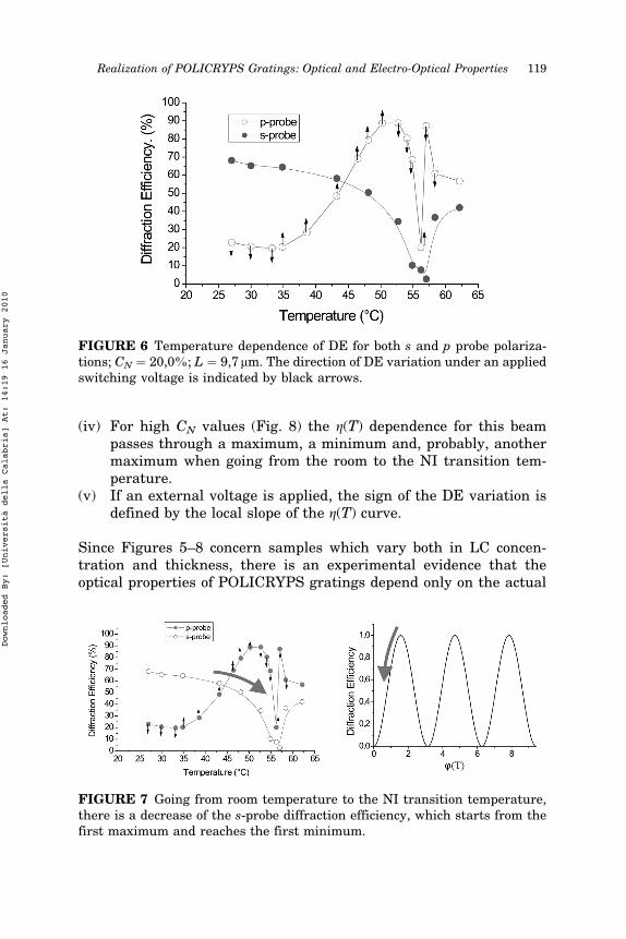
(iv) For high CN values (Fig. 8) the g(T) dependence for this beampasses through a maximum, a minimum and, probably, anothermaximum when going from the room to the NI transition tem-perature.
(v) If an external voltage is applied, the sign of the DE variation isdefined by the local slope of the g(T) curve.
Since Figures 5–8 concern samples which vary both in LC concen-tration and thickness, there is an experimental evidence that theoptical properties of POLICRYPS gratings depend only on the actual
FIGURE 7 Going from room temperature to the NI transition temperature,there is a decrease of the s-probe diffraction efficiency, which starts from thefirst maximum and reaches the first minimum.
FIGURE 6 Temperature dependence of DE for both s and p probe polariza-tions; CN " 20,0%; L " 9,7mm. The direction of DE variation under an appliedswitching voltage is indicated by black arrows.
Realization of POLICRYPS Gratings: Optical and Electro-Optical Properties 119
Downloaded By: [Università della Calabria] At: 14:19 16 January 2010

value of the multi-variable argument u of the Kogelnik function, inde-pendently of the way which has been followed to obtain that particularvalue.
There is, however, some discrepancy between experimental resultsand the theoretical ones predicted by (1). Maxima and minima valuesof the g(T) curve given by (1) hold 1 and 0 respectively, while as a mat-ter of fact, the corresponding experimental values are a little bit differ-ent. In our opinion this discrepancy can be due to some imperfection inthe grating morphology. In particular, the nematic layer thicknesswithin the fringe can vary slightly across the probe beam spot, thusleading to small variations in e1 and e$1. In this case, the experimen-tally observed g(T) dependence does not correspond directly toexpression (1), but to a superposition of several expressions of thatkind, each having slightly different values of e1 and e$1 in its argu-ment. This fact leads to the observed non-unit maxima and non-zerominima. However, detailed considerations on such features require amore precise knowledge of the morphology of each particular grating,and we will go deeper insight this argument in the future.
A KOGELNIK-LIKE MODEL FOR POLICRYPS GRATINGS
We have implemented a theoretical approach which makes use ofnumerical simulations [18]. First of all, a simple estimation showsthat, in our case the Bragg parameter holds q " 2k2=K2e1! 11, K beingthe grating fringe spacing, k the probe wavelength and e1 the firstorder Fourier coefficient of the dielectric constant profile which repre-sents the grating modulation. This value ensures that our POLI-CRYPS are thick diffraction gratings [16]. We also note that they arealmost pure phase gratings, since no variation of the total transmitted
FIGURE 8 Going from room temperature to the NI transition temperature,the p-probe diffraction efficiency passes through a maximum, a minimumand then a second maximum.
120 R. Caputo et al.
Downloaded By: [Università della Calabria] At: 14:19 16 January 2010

intensity (direct transmitted beam plus detectable diffraction orders)is observed with respect to the intensity of the probe beam transmittedbefore starting the curing process. In the case of a thick transmissiondiffraction grating with a fringe pattern perpendicular to the film sur-face we can write the following system of coupled wave equations [17]:
@E0
@z" ia ee0 % ee1& 'e$1E1
@E1
@z" ia ee1 % ee0& 'e1E0
8>><
>>:&2'
where a " x2=2c2kz and E0 and E1 are the electric field amplitudes ofthe probe and diffracted waves respectively. This system of equationscan be re-written in terms of the s and p polarization of the waves trav-elling in the grating: for the s polarization we can write the polariza-tion unit vectors of probe and diffracted waves as ee0 " &0; 0; 1' andee1 " &0; 0; 1'. By substituting in (2) we obtain:
@Es0
@z" iae0$1E
s1
@Es1
@z" iae01E
s0
8>><
>>:&3'
Where the p polarization is considered, ee0 " &cos b; 0; sin b' andee1 " &cos b; 0; $ sin b', therefore the equations are:
@Ep0
@z " ia cos 2b& 'ee$1Ep1
@Ep1
@z " iaee1Ep0
8><
>:&4'
In equations of systems (3) and (4), apexes ‘‘o’’ and ‘‘e’’ attributed to theFourier components of permittivities denote that they are polarization-dependent. Solution of systems (3) and (4) yields:
gs "Es
1 z " L& 'Es
in
####
####2
" sin2 p eo1eo$1
$ %L
&&&&eo0
pk cos b
" #
gp "Ep
1 z " L& 'Ep
in
####
####2
" sin2 p ee1ee$1
$ %cos 2b& 'L
&&&&ee0
pk cos b
" # &5'
Both solutions have a Kogelnik-like behaviour. Values of the permit-tivity components involved in (5) have to be estimated for each parti-cular shape of the fringe profile. This shape can be supposed step-like,being composed of a uniform nematic film of relative thickness n(0 < n < 1) with permittivity eo;eN and a slice of polymer of relative
Realization of POLICRYPS Gratings: Optical and Electro-Optical Properties 121
Downloaded By: [Università della Calabria] At: 14:19 16 January 2010

thickness (1$ n), with eP permittivity value. The value of n can beassumed as equal to the volume concentrationCNV * CN of the nematic.The Fourier components of permittivity can be calculated analyticallyfor this kind of profile and yield:
eO;E+1 " +
i eO;EN $ eP
! "
2pexp +2pin& ' $ 1& '
eO;E0 " eP , eO;E
N $ eP! "
n
&6'
Substitution of these values into (5) gives:
gs " sin2 eoN $ ep$ %
sin pn& '&&&&&&&&&&&&&&&&&&&&&&&&&&&&&&&&ep , eoN $ ep
$ %n
q L
k cos b
' (2
64
3
75
gp " sin2 eeN $ ep$ %
cos 2b& ' sin pn& '&&&&&&&&&&&&&&&&&&&&&&&&&&&&&&&&ep , eeN $ ep
$ %n
q L
k cos b
' (2
64
3
75
&7'
Here eoN " e? while eeN is given by the Fresnel equation
eEN " sin2 h, b& '=e? , cos2 h, b& '=ek) *$1 &8'
where h is the director pre-tilt angle in the XZ plane (see Fig. 4).
FIGURE 9 Calculated Kogelnik dependence of DE on temperature for severaln values. The thick curve represents the average of all the other curves.
122 R. Caputo et al.
Downloaded By: [Università della Calabria] At: 14:19 16 January 2010

Introduction of the temperature dependence of eN,P(T) (Fig. 2) intoEquation (7), along with typical values of experimental parameters,gives the theoretical gs,p(T) curves for different values of n for a ppolarized probe beam (Fig. 9). It is evident that the value of n dramati-cally influences the shape of these curves and the position and numberof their extrema. The average curve (thick one) confirms our hypoth-esis that the behaviour of the diffraction efficiency is strongly influ-enced by the nematic layer thickness within the grating.
COMPARISON WITH EXPERIMENTAL RESULTS
A theoretical fit of the experimental curves is reported in Figure 10,where the utilized best fit value of n coincides with its expected value,that is the NLC concentration n " CN " 0.2. This coincides also withthe value deduced from the SEM photo (Fig. 3). In order to show thesensitivity of the fit to the particular n value, we have introduced inFigure 10 a theoretical curve obtained for the p probe with a slightlydifferent (0, 18 instead of 0, 20) n value. As a result, the minimum isshifted down in temperature of 8)C.
Where the discrepancies observed in the extrema points of thep curve are concerned, we observe that, in fact, in these pointsthe Kogelnik formula is no more valid and a further perturbationtheory iteration is necessary in order to take into account the higher
FIGURE 10 Theoretical fit of experimental curves of the DE dependence ontemperature. The fit was made by putting n " 0,2 in expression (7). The con-tinuous line refers to n " 0,18.
Realization of POLICRYPS Gratings: Optical and Electro-Optical Properties 123
Downloaded By: [Università della Calabria] At: 14:19 16 January 2010

diffraction order contributions. The proper evaluation leads to a 2%diffraction efficiency for ,2nd and $1st diffraction orders, that corre-spond well enough to the experimentally observed values. In its turn,a mean deviation of about 4% from extrema values 1 and 0 well fitsthe experimental results. Finally, by examining in details the mor-phology of the grating (see Fig. 3), it turns out that the width of thenematic films is not completely uniform across the grating: a typicalscale of equal n length of the order of d " 10 mm, can be recognize, wichcorresponds to about 1% of the probe spot diameter. Therefore, it ismore realistic to consider the DE of this grating written as a sum-mation of several contributions:
gMP;S " 1
S
X
n
gP;S&nn'Sn "Z 1
$1f &n'gP;S&n'dn &9'
Here Sn is the area of nth n-homogeneous spot with nn value, S is thetotal probe cross section area, f (n) represents the ‘‘n-area distributionfunction’’ normalized to S.
Assuming this function as a rectangle of 2Dn width centred at n0,with Dn=n0 << 1, the following expression for gMp;s can be obtained:
gMP;S " 1
2Dn
Z n0,Dn
n0$Dnsin2&vP;S sin&pn''dn &10'
where:
vP "eEN $ eP$ %
cos 2b& '&&&&&&&&&&&&&&&&&&&&&&&&&&&&&&&&&&&eP , eEN $ eP
$ %n0
q L
k cos b
' (
vS "eON $ eP$ %
&&&&&&&&&&&&&&&&&&&&&&&&&&&&&&&&&&&eP , eON $ eP
$ %n0
q L
k cos b
' (
Neglecting the weak dependence on n of the square root in the denomi-nator, we expand sin(pn) of expression (10) up to the linear term, andget the following result:
gMP;S " sin2 vP;S sin pn0& '$ %
,cos 2vP;S sin pn0& '
$ %
2
- 1$sin 2pvP;S cos pn0& 'Dn
$ %
2pvP;S cos pn0& 'Dn
+ , &11'
This expression reduces to (7) in the case Dn " 0, but for a non-zerovalue of Dn it does not reach 0 and 1 extrema values. Results of fittingthe same data of Figure 11 by Expression (11) are presented in Figure
124 R. Caputo et al.
Downloaded By: [Università della Calabria] At: 14:19 16 January 2010

11, where n0 " 0.2 corresponds to CN, and a best-fit value of Dn " 0,03has been used.
SWITCHING EFFECTS
Where the diffraction efficiency dependence on an external electricfield is considered, we can observe that for an amplitude value up to13V=mm, no modifications have been observed in the diffractionefficiency of the s-polarized probe beam; the circumstance confirmsthat this beam travels in the sample as an ordinary wave. For thep polarized probe beam, the value of the electric field required toproduce a variation in the diffraction efficiency depends on the NLCconcentration CN, the typical field values (referred to as ‘‘switchingthreshold’’) varying in the range 1–5V=mm.
Results for the applied field dependence of the diffractionefficiency of a p polarized probe beam are presented in Figure 12,for a nematic concentration CN " 26%. Curves show that, afterthe switching threshold is achieved, the sign of the diffractionefficiency variation depends on the actual value of the temperature.This sign is indeed indicated in Figures 6–8 by black ‘‘increase’’ and‘‘decrease’’ arrows in correspondence of different temperature valvesand it is easy to realize that they strictly correspond to the localsign of the curve slope. This means that the diffraction efficiencyis increased by the applied field for slopes rising with temperature,
FIGURE 11 A more accurate fit of experimental curves of the DE dependenceon temperature. The fit was made by putting n " 0, 2 in expression (11) andconsidering Dn " 0, 03.
Realization of POLICRYPS Gratings: Optical and Electro-Optical Properties 125
Downloaded By: [Università della Calabria] At: 14:19 16 January 2010

while it is decreased for descending slopes. From a theoretical pointof view, we assume that the interaction of the NLC films betweenthe fringes with external electric fields can be described in theframework of continuum theory. The threshold of Fredericksz tran-sition in each nematic film, that is the ‘‘switching threshold’’, can beeasily calculated using the standard variation technique [19] whichyields:
EMINTH " 1
&n0 , Dn'KUF&T'
EMAXTH " 1
&n0 $ Dn'KUF&T'
UF&T' " 2p
&&&&&&&&&&&&&&&&pK3&T'De&T'
s&12'
Here, UF is the low-frequency threshold for pure nematic LC, K3 isthe bend Frank’s constant (in our case the deformation is bend type)and De is the low frequency permittivity anisotropy of the NLC. Dueto the range of values of the n parameter mentioned above, two lim-iting values of ETH exist, denoting the fact that fringes with differ-ent thickness of the nematic film undergo Fredericksz transition atdifferent field values. In Figure 12, the maximal and minimal values
FIGURE 12 Dependencies of the DE of the p probe beam on the applied fieldfor several temperature values; CN " 26.0%; L " 12, 4 mm.
126 R. Caputo et al.
Downloaded By: [Università della Calabria] At: 14:19 16 January 2010

of the threshold field calculated from (12) are depicted by arrows inthe g(E) curve. It can be seen that the points reasonably correspondto observed value of the switching threshold.
FUTURE DEVELOPMENTS
The features of POLICRYPS gratings give an intriguing possibility ofrealizing interesting application oriented developments. Work in thisdirection is already in progress and two main applications are actuallyunder prototyping. A holographic tuneable beam splitter can beobtained by performing a substitution of the intersection part of twoplanar intersecting waveguides with a suitable POLICRYPS grating.The device can be easily engineered to fulfil the Bragg condition andmaximize the diffraction efficiency of the grating. An optical beamentering the device can be splitted in two parts, the relative intensitiesof the obtained beams being controlled with continuity by an electro-optical control of the device.
A more sophisticate application of POLICRYPS gratings is given bya Bragg reflection filter. This is based on the concept of photonic bandgap (PBG) which represents a window of the electromagnetic spec-trum in which the propagation of light is forbidden. The presence ofa PBG allows to engineer a particular filter which is able of reflectingonly some wavelengths in a particular range of the incoming light.This kind of filter can be realized by introducing a POLICRYPSreflection grating between two consequent parts of a linear planarwaveguide.
The character of innovation of this filter is represented again by theelectro-optical control: The action of an external electric field can pro-duce a tuning over a particular range of reflected wavelengths.
CONCLUSIONS
In conclusion, we have shown that, by utilizing a UV interferencepattern and a suitable procedure, it is possible to realize a new struc-ture in which polymer and NLC components are completely separatedfrom each other, the NLC films being homogeneously aligned with thedirector perpendicular to the polymer slices. From the optical point ofview, this structure represents a Bragg diffraction grating whoseefficiency can be as high as 96–98%, exhibiting also a non-monotonictemperature dependence. This is due to the typical Kogelnik depen-dence of the DE of Bragg phase gratings upon the phase retardationmodulation which, in our case, can easily achieve the value p in
Realization of POLICRYPS Gratings: Optical and Electro-Optical Properties 127
Downloaded By: [Università della Calabria] At: 14:19 16 January 2010

10 mm thick samples. A Kogelnik-like model has been implementedwhich makes use only of real values of physical quantities (withoutnecessity of introducing any fitting parameter) and accounts for theexperimental results with good accuracy. Where the influence of anapplied electric field is concerned, threshold values for switching theDE of POLICRYPS varies in the range 3–5V=mm for gratings with a1.39 mm fringe spacing. Comparison of these values with theoreticalprediction reveals a good agreement, while the characteristic switch-ing time, which is lower than 1ms, can be further reduced in the futureby avoiding the formation of spurious polymer nets inside the nematicfilms.
REFERENCES
[1] Margerum, J. D., Lackner, A. M., Ramos, E., Smith, G. W., Vaz, N. A., Kohler, J. L.,& Allison, C. R. ‘‘Polymer dispersed liquid crystal film devices, and method offorming the same’’, United States Patent #4,938,568 (1990, filed 1988).
[2] Margerum, J. D., Lackner, A.M., Ramos, E., Smith, G. W., Vaz, N. A., Kohler, J. L.,& Allison, C. R. ‘‘Polymer dispersed liquid crystal film devices’’, United StatesPatent #5,096,282 (1992, filed 1990).
[3] Sutherland, R. L., Tondiglia, V. P., Natarajan, L. V., & Bunning, T. J. (1993). Bragggratings in an acrylate polymer consisting of periodic polymer-dispersed liquid-crystal planes. Chem. Mater., 5, 1533.
[4] Sutherland, R. L., Tondiglia, V. P., Natarajan, L. V., Bunning, T. J., & Adams,W.W.(1994). Electrically switchable volume gratings in polymer-dispersed liquid-crystals. Appl. Phys. Lett., 64, 1074.
[5] Sutherland, R. L., Tondiglia, V. P., Natarajan, L. V., Bunning, T. J., & Adams,W.W.(1996). Electro-optical switching characteristics of volume holograms in polymerdispersed liquid crystals. J. Nonl. Opt. Phys. & Materials, 5, 89.
[6] Sutherland, R. L., Tondiglia, V. P., Natarajan, L. V., Bunning, T. J., & Adams,W.W.(1995). Volume holographic image storage and electrooptical readout in a polymer-dispersed liquid-crystal film. Opt. Lett., 20, 1325.
[7] Jazbinsek, M., Olenik, I. D., Zgonik, M., Fontecchio, A. K., & Crawford, G. P. (2001).Characterization of holographic polymer dispersed liquid crystal transmission grat-ings. J. Appl. Phys., 90, 3831.
[8] Jazbinsek, M., Olenik, I. D., Zgonik, M., Fontecchio, A. K., & Crawford, G. P. (2002).Electro-optical properties of polymer dispersed liquid crystal transmission gratings.M.C & L.C., 375, 455.
[9] Duca, D., Sukhov, A. V., & Umeton, C. (1999). Detailed experimental investigationon recording of switchable diffraction gratings in polymer dispersed liquid crystalfilms by UV laser curing. Liq. Crys., 26, 931.
[10] Fuh, A. Y. G., Lee, C. R., & Ho, Y. H. (2002). Thermally and electrically switchablegratings based on polymer-ball-type polymer-dispersed liquid-crystal films. Appl.Opt., 41, 4585.
[11] Bowley,C.C.,Kossyrev, P.,Danworaphong, S., Colegrove, J.,Kelly, J., Fiske,T., Yuan,H. J., & Crawford, G. P. (2001). Improving the voltage response of holographicallyformed polymer dispersed liquid crystals (H-PDLCs).M.C & L.C., 359, 647.
[12] Lucchetta, D. E., Karapinar, R., Manni, A., & Simoni, F. (2002). Phase-only modu-lation by nanosized polymer-dispersed liquid crystals. J. Appl. Phys., 91, 6060.
128 R. Caputo et al.
Downloaded By: [Università della Calabria] At: 14:19 16 January 2010

[13] Caputo, R., De Sio, L., Sukhov, A. V., Veltri, A., & Umeton, C. (2004). Realization ofa new kind of switchable holographic grating made of liquid crystal films separatedby slices of polymeric material. Opt. Lett., 29, 1261–1263.
[14] Caputo, R., Veltri, A., Umeton, C. P., & Sukhov, A. V. (2004). Characterization of thediffraction efficiency of new holographic gratings with a nematic film-polymer-slicesequence structure. J. Opt. Soc. Am. B, 21, 1939.
[15] Hallam, B. T., Brown, C. V., & Sambles, J. R. (1999). Quantification of the surface-and bulk-order parameters of a homogeneously aligned nematic liquid crystal usingfully leaky guided modes. J. Appl. Phys., 86, 6682–6689.
[16] Gaylord, T. K. & Moharam, M. G. (1981). Thin and thick gratings: terminologyclarification. Appl. Opt., 20, 3271.
[17] Shen, Y. R. (1984). Principles of Nonlinear Optics, John Wiley & Sons: New York.[18] Caputo, R., Sukhov, A. V., Umeton, C., & Veltri, A. Characterization of the
Diffraction Efficiency of New Holographic Gratings with a Nematic Film-PolymerSlice Sequence Structure (POLICRYPS). J. Opt. Soc. Am. B (to be published).
[19] de Gennes, P. J. (1974). Physics of Liquid Crystals, Oxford University Press:Oxford.
Realization of POLICRYPS Gratings: Optical and Electro-Optical Properties 129
Downloaded By: [Università della Calabria] At: 14:19 16 January 2010
Copyright © 2022 FDOKUMEN