Nonlinear gauge realization of spacetime symmetries including translations
Upload
khangminh22Category
view
0download
0
1SCieNtifiC RepoRTS | (2018) 8:9131 | DOI:10.1038/s41598-018-27312-5
www.nature.com/scientificreports
Realization of an ultrathin acoustic lens for subwavelength focusing in the megasonic rangeJaeyub Hyun1, Yong Tae Kim1,3, Il Doh1,3, Bongyoung Ahn1,3, Kyungmin Baik1 & Se-Hwa Kim2,3
In this study, we report the first experimental realization of an ultrathin (0.14λ, λ = 1.482 mm means wavelength at 1 MHz in the water medium) subwavelength focusing acoustic lens that can surpass the Rayleigh diffraction limit (0.61λ/NA, NA means numerical aperture). It is termed a Super-Oscillatory Acoustic Lens (SOAL), and it operates in the megasonic range. The SOAL represents an interesting feature allowing the achievement of subwavelength focusing without the need to operate in close proximity to the object to be imaged. The optimal layout of the SOAL is obtained by utilizing a systematic design approach, referred to here as topology optimization. To this end, the optimization formulation is newly defined. The optimized SOAL is fabricated using a photo-etching process and its subwavelength focusing performance is verified experimentally via an acoustic intensity measurement system. From these measurements, we found that the proposed optimized SOAL can achieve superior focusing features with a Full Width at Half Maximum (FWHM) of ~0.40λ/NA ≃ 0.84 mm (for our SOAL, NA = 0.707) with the transmission efficiency of 26.5%.
The achievement of the subwavelength focusing feature, which focuses acoustic power into a very small region, is a most important task in the medical ultrasound field, from diagnostics1 to therapeutics2. The achievement of subwavelength focusing makes it possible to discover and cure very tiny substances, such as cancer and tumors, which not easily detected by typical medical ultrasound imaging and therapy systems. In other words, such an achievement indirectly implies that one can provide better medical service to more people. Unfortunately, cur-rent systems have a focusing limit which relates approximately to the wavelength of the wave used. Formally, the focusing limit, d, is limited by the wavelength of the wave used, λ, and the Numerical Aperture (NA) of the imaging system as d = 0.61λ/NA (i.e., the Rayleigh diffraction limit)3,4. Meanwhile, to overcome this diffraction limit and realize acoustic imaging and therapy systems with subwavelength focusing performance, acoustic lenses can be considered as a viable solution. In general, acoustic lenses can be classified into two types according to the utilization of evanescent waves. Evanescent waves are an important factor in terms of focusing and imaging, because these types of waves contain subwavelength fine information pertaining to the object5.
More specifically, acoustic lenses which utilize an evanescent wave can be realized through an artificially designed microstructure known as an Acoustic MetaMaterial (AMM). Examples include acoustic superlenses6 and acoustic hyperlenses7. AMM-based lenses demonstrate extremely improved focusing limits (0.05λ/NA in8). However, the object to be imaged should be placed close to the lens for the coupling of the near-field evanescent wave to the lens. In other words, it is difficult to apply these AMM-based lenses to conventional far-field imaging methods based on a pulse-echo scheme in which the object would be placed far away from the lens9–11. Moreover, although the principle of the AMM-based lenses has been experimentally proven6–8,12, manufacturing a microstructure of such a lens in the megasonic range (>1 MHz) involves significant challenges related to fabrication quality and the control of energy losses. Hence, if one can realize an acoustic lens with a subwavelength focusing feature without using an evanescent wave, it will be a very powerful solution for clinical applications in practice. Based on this need, a conventional refractive-type concave acoustic lens which is attached to the front of the source transducer is commonly used13. This type of acoustic lens has the advantages of easy fabrication and far-field imaging. However, its range of application is
1Center for Medical Convergence Metrology, Korea Research Institute of Standards and Science (KRISS), 267 Gajeong-ro, Yuseong-gu, Daejeon, 34113, Republic of Korea. 2Center for Nano-Bio Measurement, Korea Research Institute of Standards and Science (KRISS), 267 Gajeong-ro, Yuseong-gu, Daejeon, 34113, Republic of Korea. 3Department of Medical Physics, Korea University of Science and Technology, 176 Gajeong-ro, Yuseong-gu, Daejeon, 34113, Republic of Korea. Correspondence and requests for materials should be addressed to Y.T.K. (email: [email protected])
Received: 30 January 2018
Accepted: 23 May 2018
Published: xx xx xxxx
OPEN

www.nature.com/scientificreports/
2SCieNtifiC RepoRTS | (2018) 8:9131 | DOI:10.1038/s41598-018-27312-5
limited generally due to both its large size and poor detachability. It is also difficult to overcome the aforementioned diffraction limit through this type of acoustic lens. Thus, to realize a more compact acoustic lens, a planar acoustic lens that can focus acoustic power by modulating the phase delay of the acoustic wave, such as a Fresnel Zone Plate (FZP) lens, was proposed14–16. Many previous studies on both the design and experimental realization of a planar acoustic lens are reviewed and summarized in this study (see Table S1 in the Supplementary Note). In fact, as shown in Table S1, a variety of attempts at the practical realization of a planar acoustic lens have been reported thus far, but subwavelength focusing with these planar lenses remains a difficult problem. To overcome this limitation, several Acoustic MetaSurface (AMS)-based lenses have recently been proposed17–19. However, because the configuration of several AMS-based lenses is highly complex (e.g., a coiled structure or a labyrinthine structure), they have been experimentally realized only for use in an air medium in the audible frequency range. For a water medium in the megasonic range, there are no practically realizable acoustic lenses due to the difficulty in manufacturing such lenses. The previous studies in this area provide evidence that an ultrathin planar acoustic lens capable of subwavelength focusing in megasonic range remains unrealized. In particular, we also focus on the megasonic range (>1 MHz) here as the target operational frequency because it is easy to measure a megasonic beam through a hydrophone with a very small aperture because the wavelength is relatively large in water. If the megasonic beam is measured through a hydrophone with an aperture of a size comparable to the wavelength, an accurate FWHM cannot be measured due to the size effect20.
Meanwhile, in 1952, Toraldo di Francia suggested that concepts of super-directive antennas could be applied to optical instruments to increase their spatial resolution beyond the diffraction limit21. The super-directive antenna could make an arbitrarily narrow beam by precisely tailoring the interference of waves. Since then, the idea of super-directive antennas has been extended to the phenomenon as now known today as super-oscillation through many studies5,22–26. In 2012, in the optical field, one study revealed that a remarkable planar optical lens known as a Super-Oscillatory Lens (SOL) is capable of subwavelength focusing27. The concept of super-oscillation used in that study27 corresponds to a phenomenon in which an image waveform oscillates even more rapidly than the highest constitutive frequency component of the original image waveform in the main focusing area. That study achieved the subwavelength focusing feature at a position 10λ away from the optical lens, with the config-uration designed using a Particle Swarm Optimization (PSO) algorithm. This was the first report of the concept of an SOL being applied to optical imaging as a practical solution for subwavelength focusing and imaging. The attractive feature of the SOL is that it can provide subwavelength focusing without utilizing evanescent waves. In other words, the subwavelength focusing feature can only be achieved through a propagation wave. Therefore, unlike existing metamaterial-based lenses, there is no need to place an object very close to the SOL. This implies that it is possible to realize far-field subwavelength focusing through the SOL. In the acoustic field, as a counter-part to this optical SOL, the feasibility of realizing the acoustical super-oscillation phenomenon was examined in 201428. That study theoretically achieved subwavelength focusing by adjusting the radius of a piezoelectric annular ring. Unfortunately experimental realization was not carried out. Moreover, the ideal assumption of no mechanical crosstalk between neighboring annular ring-type piezoelectric elements was considered. Meanwhile, practical design factors including the source condition, operational frequency, target subwavelength focusing area, and lens thickness should be considered during the design process in order to obtain a realizable and appli-cable SOAL. The aforementioned studies used design methodologies based on a heuristic algorithm, such as PSO or a Genetic Algorithm (GA)27,29, to consider these design factors. These design methodologies have the advan-tage of easy implementation, but the computational cost is very high and the process is time consuming. Also, layouts of the designed SOAL are limited to simple configurations.
Thus, this study describes the development of a systematic inverse design process of a SOAL based on topol-ogy optimization to determine the optimal material distribution in a desired design domain30 so as to resolve several disadvantages of existing design methodologies and achieve an efficient design. Furthermore, to the best of our knowledge, this is the first study in which an optimized SOAL is experimentally realized and the subwave-length focusing feature is achieved in the megasonic range.
ResultsDemonstration of the super-oscillation phenomenon and its extension to a subwavelength focusing acoustic lens. Above all, the super-oscillation mechanism of the proposed megasonic SOAL can be demonstrated simply using a one-dimensional (1D) wave composed of six spatial Fourier components, follow-ing a previous earlier approach31. The 1D super-oscillating function can be defined by f(r) in Eq. (1), where r is the lateral position normalized by the radius of a source transducer.
∑= π==f r A e( ) (1)n
nn
j nr05 2
In this equation, An denotes the Fourier coefficients (here, we use A0 = 19.0123, A1 = −2.7348, A2 = −15.7629, A3 = −17.9047, A4 = −1.0000, A5 = 18.4910). In Fig. 1a, we show the acoustic intensity of the original wave f r( ) 2 (i.e., solid blue line) and its fastest Fourier component = πf P rcos(10 )fastest (i.e., dashed red line). Here, the term “fastest” refers to the spatially fastest oscillating component by the components of the original wave at the highest frequency. As represented in the lower panel in Fig. 1a, we note that there is a narrow peak, about ten times narrower
= πf P rcos(500 )Asym than the fastest Fourier component of the original wave near r = 0. From this 1D demonstra-tion, we can find that super-oscillation refers to a waveform which oscillates faster than the highest constitutive fre-quency components of the original wave, in the finite interval (e.g., the desired main focusing area). Thus, it is important to note that the subwavelength focusing feature is guaranteed only in this finite area. As shown in this simple 1D demonstration, subwavelength focusing based on the super-oscillation phenomenon can be achieved by controlling both the amplitude (Fourier coefficient) and the phase (2πnr) of the wave diffracted from the micro-slit of the lens.

www.nature.com/scientificreports/
3SCieNtifiC RepoRTS | (2018) 8:9131 | DOI:10.1038/s41598-018-27312-5
Meanwhile, the subwavelength feature of a super-oscillatory wave should be accompanied by high-amplitude regions outside the desired main focusing area. This undesired region is termed a side lobe. In order to improve the focusing performance of the lens (i.e., an even narrower FWHM), an undesired side lobe is an inevitable result because the relationship between the desired and undesired regions has trade-off. Indeed, the SOAL can achieve any amount of FWHM or resolution at the expense of side lobes. Therefore, it is necessary to select the proper size of the desired main focusing area when attempting to design the SOAL practically, in order to make the side lobe smaller than the main focusing area. As shown in Fig. 1b, the SOAL can be realized through a binary ring mask with a spatially varying phase and amplitude. The binary ring mask-type SOAL is a promising technology for achieving subwavelength focusing based on the super-oscillation phenomenon27. It can be manufactured easily using existing microfabrication techniques, such as a photo-etching process32. Given this advantage, we selected the binary ring mask-type SOAL as a means to realize subwavelength focusing in this study. The aforementioned original wave can be transformed into a super-oscillatory waveform with the subwavelength focusing feature using this SOAL. In the next section, we present the physically quantifiable optimization formulation used to design the optimal layout of the binary ring mask-type SOAL.
Figure 1. Megasonic SOAL and its fundamental mechanism. (a) Fundamental mechanism of the 1D super-oscillating function. Upper panel: the super-oscillating function (Eq. (1), solid blue line) and corresponding fastest Fourier component = πf P rcos(10 )fastest (dashed red line). Lower panel: zoomed-in view of the function near r = 0. There is a narrow peak, about ten times narrower than the fastest Fourier component of the original wave near r = 0. This narrow peak can be approximated by = πf P rcos(500 )Asym (dotted-circle green line). The super-oscillating function can be separated into the two regions: the desired main focusing area and the undesired side lobe. (b) A SOAL with a binary ring mask controls both the phase and amplitude. Through the SOAL, the incident original acoustic plane wave can be transformed into a needle-type focused beam.

www.nature.com/scientificreports/
4SCieNtifiC RepoRTS | (2018) 8:9131 | DOI:10.1038/s41598-018-27312-5
The optimal layout of the megasonic super-oscillatory acoustic lens. We used topology optimiza-tion, which is one of the most flexible types of inverse design methods, since topological changes such as increase or decrease in the number of holes in the desired design domain are allowed during the design optimization pro-cess30. To obtain the optimal layout of the binary ring mask-type SOAL, a numerical model should be considered in both the analysis and design steps. Figure 2a shows the configuration of the numerical model. Here, we used the two-dimensional (2D) axisymmetric finite element model to solve the acoustic wave propagation problem in the megasonic range efficiently based on the Helmholtz equation. The region for the optimal layout of the SOAL (i.e., the design domain, Ωde in Fig. 2a) is located at a position 10 mm away from the source transducer (Γin in Fig. 2a), which can be modeled using a plane wave boundary condition (ΓABC in Fig. 2a). We enclosed the analysis and design domain with an absorbing boundary to prevent the wave reflection from the exterior boundary33. The radius and height (i.e., the thickness of the SOAL) of the design domain are 30 mm and 0.2 mm, respectively. The position of the target main focusing area (Ωb in Fig. 2a) is located 25 mm (i.e., about 16.6λ) away from the design domain. Meanwhile, acoustically opaque and transparent regions are required to design the layout of the SOAL. To create these regions, in this study SUS 303 material (mass density, ρS = 8,000 kg/m3 and sound speed,
Figure 2. Numerical model for both the analysis and design of the binary ring mask-type SOAL. (a) Configuration of the numerical model for the topological design of the layout of the binary ring mask-type SOAL. The red crosses in the red box indicate the specific points to compute the constraint (g2) related to the target FWHM. (b) Topology optimization history. The image shows the evolution of the 2D topological layout of the SOAL and the acoustic power during the optimization process. The black area represents the SUS 303 material, while the white region represents water. The acoustic power J( )AP
b in the main focusing area gradually increases. The points from A to F in the figure indicate the design iterations selected to show the evolution of the optimal layout. From the optimal layouts of SOAL obtained in these selected design iterations (Right panel in b), we confirm that layout of the SOAL converges well during the optimization process. The initial layout (i.e., point A) shows a nearly black-scale rectangle because the optimization process starts with the area fully filled with the solid material (i.e., SUS 303). The final layout (i.e., point F) of the SOAL converges well.

www.nature.com/scientificreports/
5SCieNtifiC RepoRTS | (2018) 8:9131 | DOI:10.1038/s41598-018-27312-5
cS = 4,484 m/s) and water (ρw = 1,000 kg/m3 and cw = 1,482 m/s) are used for the acoustically opaque and trans-parent regions, respectively. In this study, the shear deformation effect of elastic solid (i.e., SUS 303) was ignored during numerical simulation and optimization process of the SOAL. The Supplementary Note contains more detailed information of this issue.
As mentioned in the previous section, in principle the SOAL allows any value of FWHM. However, the larger side lobe should be accompanied in order to achieve the narrower FWHM. In particular, if the FWHM of main focusing area exceeds a certain critical value, the acoustic intensity in the side lobe becomes larger than that in the main focusing area. In other words, the increase in acoustic intensity in the side lobe should be sacrificed to design the SOAL exhibiting the even narrower FWHM. This large side lobe effect is inevitable in designing the super-oscillatory optical/acoustic lenses with very narrow FWHM31. Therefore, we set the target FWHM of the SOAL to ~λ/2 (red box in Fig. 2a), in order to make the acoustic intensity in the side lobe smaller than that in the main focusing area. Meanwhile, despite the possibility of designing the SOAL with the narrower FWHM, this study does not focus on the design of SOAL with FWHM narrower than λ/2 from the following three perspec-tives: (1) imaging (diagnosis), (2) therapeutic, and (3) thermal-viscous loss. For a detailed description of this issue, see the Supplementary Note. For a systematic design of the binary ring mask-type SOAL for subwavelength focusing, a constraint related to the target FWHM is introduced in the topology optimization setup. Generally, an acoustic lens is optimized by maximizing only the acoustic power J( )AP
b in the main focusing area34. However, in order to guarantee the subwavelength focusing feature of the SOAL here, we introduce a constraint (g2) related to the target FWHM in addition to an objective function J( )AP
b . Note that this is a simple but very powerful optimi-zation formulation for the design of the SOAL. In this study, the topology optimization setup used to design the layout of the SOAL is expressed as Eq. (2). In this equation, the mathematical meaning of γ Jmax 0e
is to determine the design variables (γe) that maximize the objective function expressed as J0. Here, J0 is the acoustic power in the main focusing area J( )AP
b . Acoustic power can be defined by the surface integral of acoustic intensity. Also, it is worth noting that acoustic intensity is proportional to the square of acoustic pressure under the assumption of the progressive plane wave. Thus, in this study, acoustic intensity is calculated from the acoustic pressure parameters using ρp c/2 w w
2 , with p being the acoustic pressure, ρw the mass density of water, and cw the sound speed of water35. p 2 is the squared absolute pressure.
∫∫
ρ
γ
ε
γ γ γ γ
= = Ω
=Ω
− ≤
=
.−
≤
= ∈
Ω
Ω
~
J Jc
p d
gd
VFF V
gp
p
max 12
subject to( )
1 0
0 51
[ , , , ] (0 1) (2)
r APb
w w
e
de
P
P
e NE
02
1
2
2
2
2
1 2
eb
de
FWHM
center
where, γe is the design variable, which varies from 0 to 1 during the topology optimization process. VFF is the required volume fraction that defines the ratio of the opaque region to the entire design domain. Vde is the volume of the entire design domain. ε is the threshold value for relaxation of the constraint g2
36. In this study, this value is set to 10−3. NE is the total number of design variables. Here, according to the updated design variable γe, the material distribution in the design domain can be determined based on Eqs (3) and (4). When γe = 0, the acoustic material corresponds to water (i.e., the acoustically transparent region), and when γe = 1, the acoustic material corresponds to SUS 303 (i.e., the acoustically opaque region).
ρ γρ
γρ ρ
=
+
−
−
( ) 1 1 1
(3)e
weq
S w
1
1
γ γ=
+
−
−
cc c c
( ) 1 1 1
(4)e
weq
S w
1
2
In these equations, q1 and q2 are penalty factors for the mass density ρ, and the speed of sound c, respectively. These penalty factors are used to improve the convergence rate of the optimization process. These values are set to 1.5 in this study. The method of moving asymptotes (MMA) is then used as the optimization algorithm37. This type of optimization algorithm requires the first-order derivative information (i.e., the gradient) of the objective function, called the design sensitivity, in order to update the design variable. Thus, we carry out an efficient design sensitivity analysis based on the adjoint variable method (AVM) to compute the gradient information. Additional details about this procedure are available in the literature38. Figure 2b shows the evolution of both the acoustic power (i.e.,J and JAP
bAPd ) and the 2D topological optimal layout of the SOAL. Here, JAP
d indicates the acoustic power in the dark area which is obtained by excluding the main focusing area from entire area (Fig. 2a). The initial layout shows a nearly black-scale rectangle because the optimization process starts with the area fully filled with the solid material (i.e., SUS 303). Here, in order to find pure 0–1 solutions (i.e., the perfect binary ring mask-type SOAL), a Heaviside projection filtering method with beta-continuation is applied every 50 iterations39. Therefore,
www.nature.com/scientificreports/
6SCieNtifiC RepoRTS | (2018) 8:9131 | DOI:10.1038/s41598-018-27312-5
the objective function (i.e., acoustic power JAPb ) jumps slightly every 50 iterations, as shown in the topology opti-
mization history plot in Fig. 2b. This optimization history confirms that the layout of the SOAL converges well during the optimization process. Moreover, the proposed systematic design methodology is equally applicable to the inverse design of a multilayer-type SOAL in addition to the aforementioned SOAL with a single layer. The Supplementary Note contains more detailed design results.
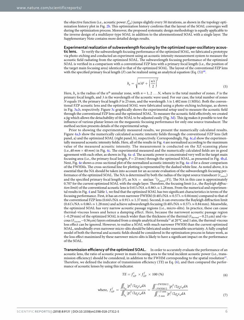
Experimental realization of subwavelength focusing by the optimized super-oscillatory acous-tic lens. To verify the subwavelength focusing performance of the optimized SOAL, we fabricated a prototype via photo-etching and conducted an experiment using an acoustic intensity measurement system to measure the acoustic field radiating from the optimized SOAL. The subwavelength focusing performance of the optimized SOAL is verified in a comparison with a conventional FZP lens with a primary focal length (i.e., the position of the target main focusing area) identical to that of the optimized SOAL. The layout of the conventional FZP lens with the specified primary focal length (F) can be realized using an analytical equation (Eq. (5))40.
λ λ= +
b n F n
2 (5)n
2
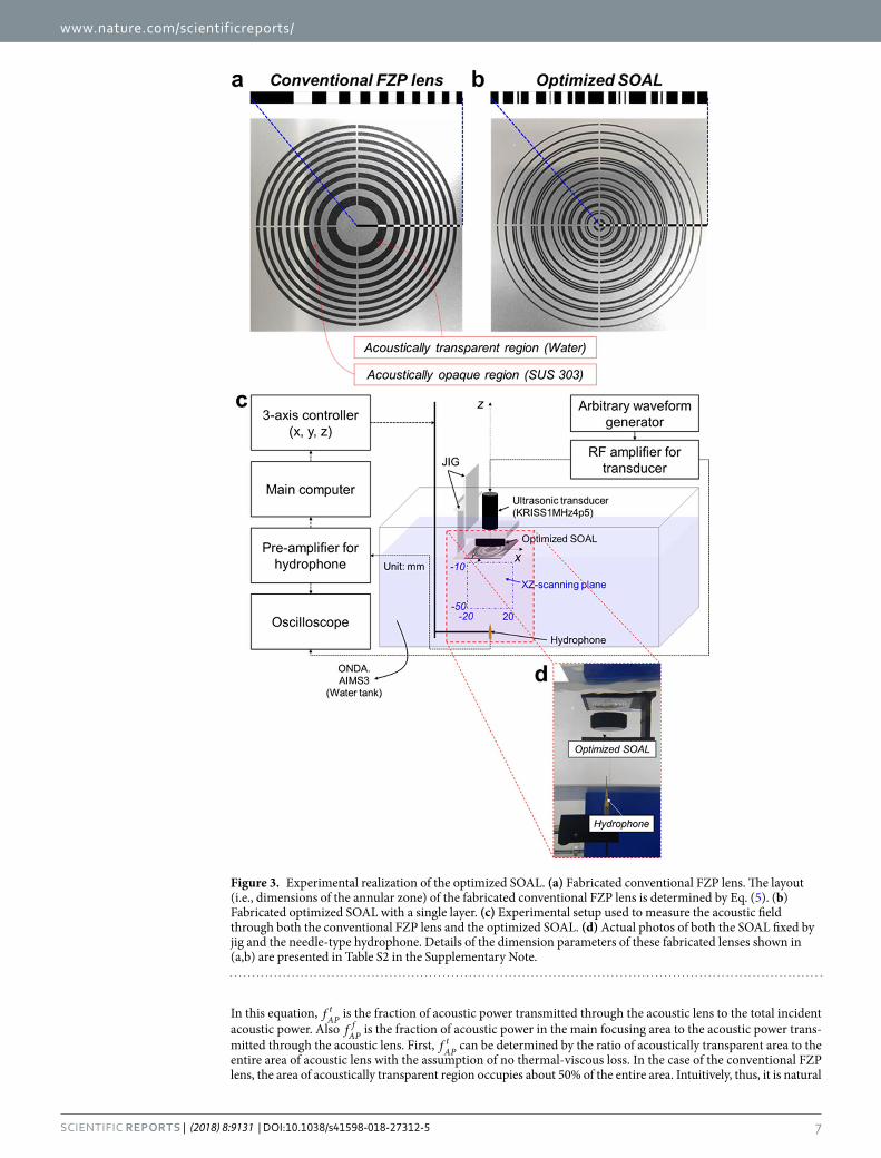
Here, bn is the radius of the nth annular zone, with n = 1, 2 … N, where is the total number of zones. F is the primary focal length, and λ is the wavelength of the acoustic wave used. For our case, the total number of zones N equals 19, the primary focal length F is 25 mm, and the wavelength λ is 1.482 mm (1 MHz). Both the conven-tional FZP acoustic lens and the optimized SOAL were fabricated using a photo-etching technique, as shown in Fig. 3a,b, respectively. Figure 3c graphically shows the experimental setup used to measure the acoustic field through the conventional FZP lens and the optimized SOAL. To measure the acoustic field effectively, we created a jig which allows the detachability of the SOAL to be adjusted easily (Fig. 3d). This jig makes it possible to test the influence of various planar lenses on the megasonic focusing performance for only one source transducer. The method section presents details of the experimental setup.
Prior to showing the experimentally measured results, we present the numerically calculated results. Figure 4a,b show the numerically calculated acoustic intensity fields through the conventional FZP lens (left panel, a) and the optimized SOAL (right panel, b), respectively. Correspondingly, Fig. 4c,d show the experimen-tally measured acoustic intensity fields. Here, all of the results in Fig. 4 are normalized according to the maximum value of the measured acoustic intensity. The measurement is conducted on the XZ-scanning plane (i.e.,40 mm × 40 mm) in Fig. 4c. The experimental measured and the numerically calculated fields are in good agreement with each other, as shown in Fig. 4a–d. The acoustic power is concentrated very well in the target main focusing area (i.e., the primary focal length, F = 25 mm) through the optimized SOAL, as presented in Fig. 4b,d. Next, Fig. 4e shows a cross-sectional plot of the normalized acoustic intensity in Fig. 4a–d for a closer comparison of the FWHMs. The cross-sectional line for plotting is represented by the dashed white line. As noted above, it is essential that the NA should be taken into account for an accurate evaluation of the subwavelength focusing per-formance of the optimized SOAL. The NA is determined by both the radius of the input source transducer (rsource) and the specified primary focal length (F), as = − r FNA sin(tan ( / ))source
1 . The NA in this case is approximately 0.707 for the current optimized SOAL with the single layer. Therefore, the focusing limit (i.e., the Rayleigh diffrac-tion limit) of the conventional acoustic lens is 0.61λ/NA ≃ 0.86λ ≃ 1.28 mm. From the numerical and experimen-tal results in Fig. 4 and Table 1, we find that the optimized SOAL has two significant characteristics in terms of the focusing performance. First, it has an even narrower FWHM (0.40λ/NA ≃ 0.57λ ≃ 0.84 mm) compared to that of the conventional FZP lens (0.64λ/NA ≃ 0.91λ ≃ 1.37 mm). Second, it can overcome the Rayleigh diffraction limit (0.61λ/NA ≃ 0.86λ ≃ 1.28 mm) and achieve subwavelength focusing (0.40λ/NA ≃ 0.57λ ≃ 0.84 mm). Meanwhile, the optimized SOAL has very narrow acoustic passage regions (i.e., micro-slits). In practice, these can cause thermal-viscous losses and hence a damping effect. Here, because the narrowest acoustic passage region (~0.29 mm) of the optimized SOAL is much wider than the thickness of the thermal (δthermal ~ 0.21 μm) and vis-cous (δviscous ~ 0.56 μm) layers estimated from a simple analytical formula35 at 20 °C and 1 atm, the thermal-viscous loss effect can be ignored. However, to realize a SOAL with much narrower FWHM than the current optimized SOAL, undoubtedly even narrower micro-slits should be fabricated under reasonable uncertainty. A fully coupled model of both the thermal and acoustic fields should be considered in the optimization process in future work, as the loss effect maximized by these narrower micro-slits is likely to have a significant impact on the performance of the SOAL.
Transmission efficiency of the optimized SOAL. In order to accurately evaluate the performance of an acoustic lens, the ratio of acoustic power in main focusing area to the total incident acoustic power (i.e., trans-mission efficiency) should be considered, in addition to the FWHM corresponding to the spatial resolution41. Therefore, we defined the indicator of transmission efficiency (TE) as Eq. (6), and then compared the perfor-mance of acoustic lenses by using this indicator.
= × ×TE f f 100 (%) (6)APt
APf
ρ
ρ
ρ
ρ= = −
+
−
+
∬∬
∬
∬f
p c dA
p c dA
p c dA
p c dAwhere,
/2
/2
/2
/2 (7)APf S w w
S w w
FWHM
FWHMw w
mm
mmw w
2
2/2
/2 2
3
3 2M
E
www.nature.com/scientificreports/
7SCieNtifiC RepoRTS | (2018) 8:9131 | DOI:10.1038/s41598-018-27312-5
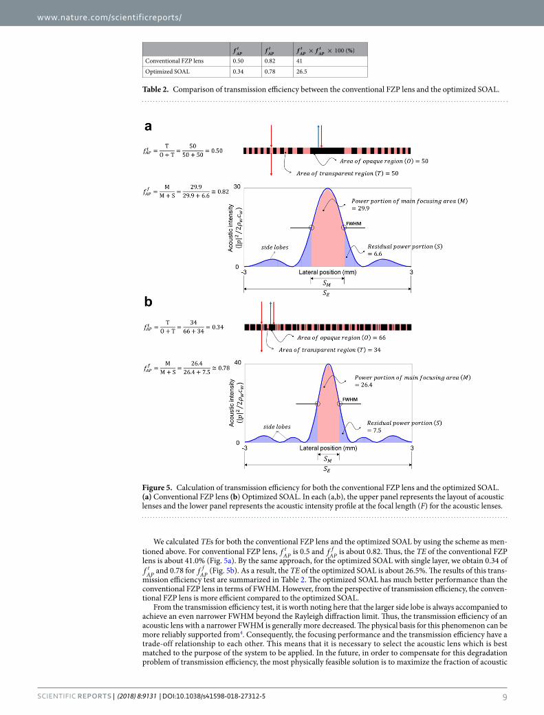
In this equation, fAPt is the fraction of acoustic power transmitted through the acoustic lens to the total incident
acoustic power. Also fAPf is the fraction of acoustic power in the main focusing area to the acoustic power trans-
mitted through the acoustic lens. First, fAPt can be determined by the ratio of acoustically transparent area to the
entire area of acoustic lens with the assumption of no thermal-viscous loss. In the case of the conventional FZP lens, the area of acoustically transparent region occupies about 50% of the entire area. Intuitively, thus, it is natural
Figure 3. Experimental realization of the optimized SOAL. (a) Fabricated conventional FZP lens. The layout (i.e., dimensions of the annular zone) of the fabricated conventional FZP lens is determined by Eq. (5). (b) Fabricated optimized SOAL with a single layer. (c) Experimental setup used to measure the acoustic field through both the conventional FZP lens and the optimized SOAL. (d) Actual photos of both the SOAL fixed by jig and the needle-type hydrophone. Details of the dimension parameters of these fabricated lenses shown in (a,b) are presented in Table S2 in the Supplementary Note.

www.nature.com/scientificreports/
8SCieNtifiC RepoRTS | (2018) 8:9131 | DOI:10.1038/s41598-018-27312-5
to expect that approximately 50% of the total incident acoustic power is assuredly to be transmitted. In this case, fAP
t is 0.5. Next, fAPf can be calculated as the ratio of the energy portions occupied by the main focusing area (SM)
and the entire area (SE) in the acoustic intensity profile at the focal length (F), as expressed by Eq. (7). To calculate these areas from the acoustic intensity profile numerically, a trapezoidal integration scheme was utilized.
Figure 4. Comparison between the numerical and experimental results of the optimized SOAL with a single layer in terms of the subwavelength focusing performance. (a,b) Numerically calculated acoustic intensity fields by the conventional FZP lens (left panel, a) and the optimized SOAL (right panel, b). (c,d) Experimentally measured acoustic intensity field radiated by the conventional FZP lens (left panel, c) and the optimized SOAL (right panel, d). (e) Comparison of the normalized acoustic intensity fields. The cross-section line of measurement along the lateral direction is represented by the dashed white line.
Numerically calculated FWHM
Experimentally measured FWHM
Rayleigh diffraction limit (The focusing limit)
Conventional FZP lens 1.24 1.371.28
Optimized SOAL 0.78 0.84
Table 1. Comparison between the numerically calculated and the experimentally measured FWHMs in Fig. 4 (unit: mm).
www.nature.com/scientificreports/
9SCieNtifiC RepoRTS | (2018) 8:9131 | DOI:10.1038/s41598-018-27312-5
We calculated TEs for both the conventional FZP lens and the optimized SOAL by using the scheme as men-tioned above. For conventional FZP lens, fAP
t is 0.5 and fAPf is about 0.82. Thus, the TE of the conventional FZP
lens is about 41.0% (Fig. 5a). By the same approach, for the optimized SOAL with single layer, we obtain 0.34 of fAP
t and 0.78 for fAPf (Fig. 5b). As a result, the TE of the optimized SOAL is about 26.5%. The results of this trans-
mission efficiency test are summarized in Table 2. The optimized SOAL has much better performance than the conventional FZP lens in terms of FWHM. However, from the perspective of transmission efficiency, the conven-tional FZP lens is more efficient compared to the optimized SOAL.
From the transmission efficiency test, it is worth noting here that the larger side lobe is always accompanied to achieve an even narrower FWHM beyond the Rayleigh diffraction limit. Thus, the transmission efficiency of an acoustic lens with a narrower FWHM is generally more decreased. The physical basis for this phenomenon can be more reliably supported from4. Consequently, the focusing performance and the transmission efficiency have a trade-off relationship to each other. This means that it is necessary to select the acoustic lens which is best matched to the purpose of the system to be applied. In the future, in order to compensate for this degradation problem of transmission efficiency, the most physically feasible solution is to maximize the fraction of acoustic
Figure 5. Calculation of transmission efficiency for both the conventional FZP lens and the optimized SOAL. (a) Conventional FZP lens (b) Optimized SOAL. In each (a,b), the upper panel represents the layout of acoustic lenses and the lower panel represents the acoustic intensity profile at the focal length (F) for the acoustic lenses.
f APt f AP
t × ×f f %100 ( )APt
APt
Conventional FZP lens 0.50 0.82 41
Optimized SOAL 0.34 0.78 26.5
Table 2. Comparison of transmission efficiency between the conventional FZP lens and the optimized SOAL.

www.nature.com/scientificreports/
1 0SCieNtifiC RepoRTS | (2018) 8:9131 | DOI:10.1038/s41598-018-27312-5
power transmitted through acoustic lens to the total incident acoustic power f( )APt . To achieve this goal, an
impedance-matched acoustic metasurface or resonance-based energy amplification could be applied.Finally4 clarified more reasonable criteria about overcoming the diffraction limit in the focusing application
as the following two: (1) The smallest period of the spatial Fourier components in the image plane is less than λ/2, (2) More than approximately 50% of the incident acoustic power is focused in the main focusing area. Indeed, our study has focused on the first criterion. The optimized SOAL shows that the acoustic intensity profile in the main focusing area in the image plane can locally oscillate faster than the highest spatial Fourier component of original acoustic wave. In other words, our optimized SOAL can overcome the diffraction limit under the first criterion. On the other hand, the optimized SOAL violates the second criterion, but this issue is not big for some imaging applications.
DiscussionIn this study, we optimized an ultrathin (0.14λ) SOAL with a subwavelength focusing feature that can focus inci-dent acoustic power into a subwavelength area in water. To design the optimal layout of the SOAL systematically, we applied an inverse design methodology known as topology optimization. By utilizing the proposed inverse design methodology, the SOAL was designed to maximize the focusing performance of the acoustic power in terms of the FWHM. We confirmed for the first time from the experimental realization of the SOAL that the optimized SOAL can overcome the diffraction limit and achieve subwavelength focusing with the FWHM of ~0.40λ/NA ≃ 0.84 mm (for our SOAL, NA = 0.707). By adding constraints on the minimization of side lobes to the current topology optimization formulation, the SOAL exhibiting a much improved focusing limit and better resolution (e.g., FWHM of . λ~0 20 /NA) can be achieved. The optimized SOAL in this study shows the transmis-sion efficiency of 26.5%. For more practical diagnostic and therapeutic processes in clinical situations, the acous-tic power should be focused at a position far (i.e., λz ) from the acoustic lens. Specifically, the acoustic lens should have a long focal length. Since the optimized SOAL can focus acoustic power into a position approxi-mately 16λ far away from that lens, we expect that it can offset some of the disadvantages of near-field imaging approaches, including those using several AMM-based lenses. Although a solution to the thermal-viscous loss effect owing to the very narrow micro-slits remains to be discovered, the optimized SOAL has a great advantage in terms of practical applications. Moreover, the optimized SOAL has several other benefits, such as the potential for low-power therapy, far-field focusing with a long focal length, and control of the focal length simply by replac-ing the optimized SOAL. Therefore, it will likely improve the therapeutic performance of High-Intensity Focused Ultrasound (HIFU)/High-Intensity Therapeutic Ultrasound (HITU)42. The optimized SOAL will also be applied to acoustic microscopy in order to realize super-resolution acoustic imaging in practice. The concept of the opti-mized SOAL can be extended to various wave-based systems (e.g., elastic, acoustic, and optical waves) through a design process similar to that proposed here.
MethodsFinite element numerical simulation. Throughout the paper, the Finite Element Method (FEM) based on the commercial software COMSOL Multiphysics and MATLAB is employed for both the numerical analy-sis and the design optimization of the SOAL. The materials used in the simulations are water and SUS 303. A time-harmonic analysis is conducted at 1 MHz operational frequency to compute the acoustic field through the optimized SOAL. Second-order Sommerfeld absorbing boundary conditions are set on the exterior boundaries of the simulation domain to eliminate boundary-reflected acoustic waves. The source transducer is approximated by the plane wave boundary condition. The proper mesh element size (hmax) is selected as the 1/10 of the wavelength (λ/10) through the convergence test. The convergence test result is shown in the Supplementary Note.
Experimental setup. The experimental setup consists of a transducer, a hydrophone, an arbitrary waveform generator, an amplifier, and a water tank (Fig. 3c). The transducer (KRISS1MHz4p5, Korea Research Institute of Standards and Science) is used to create the 1 MHz frequency plane wave. A needle-type hydrophone with a diameter of 500 μm (Precision Acoustics) with a submersible preamplifier is used to measure the acoustic field accurately through an acoustic lens. We also use an arbitrary waveform generator (33250A, Agilent Technologies) to generate a 15-cycle tone-burst signal of 200 mVrms at 1 MHz. To amplify the generated tone-burst signal, a RF amplifier (2100 L, Electronics & Innovation, Ltd.) is used. The transducer and needle-type hydrophone are installed in a tank with deionized and degassed water, and the arbitrary waveform generator and RF amplifier are installed outside the tank. The acoustic field through the acoustic lens is then measured by an acoustic intensity measurement system (AIMS III with Soniq software, ONDA).
References 1. Szabo, T. L. Diagnostic ultrasound imaging: inside out, second ed. (Elsevier Academic Press, Oxford 2004). 2. Hill, C. R., Haar, G. R. ter & Bamber, J. C. Physical principles of medical ultrasonics, second ed. (John Wiley & Sons Ltd, West Sussex
2004). 3. Hecht, E. Optics, (Addison-Wesley, Reading 2002). 4. Maznev, A. A. & Wright, O. B. Upholding limit in the focusing of light and sound. Wave Motion 68, 182–189 (2017). 5. Huang, F. M. & Zheludev, N. I. Super-resolution without evanescent waves. Nano Lett. 9, 1249–1254 (2009). 6. Park, J. J., Park, C. M., Lee, K. J. B. & Lee, S. H. Acoustic superlens using membrane-based metamaterials. Appl. Phys. Lett. 106,
051901 (2015). 7. Li, J. et al. Experimental demonstration of an acoustic magnifying hyperlens. Nat. Mater. 8, 931–934 (2009). 8. Zhu, J. et al. A holey-structured metamaterial for acoustic deep-subwavelength imaging. Nat. Phys. 7, 52–55 (2011). 9. Raum, K. & O’Brien, W. D. Jr. Pulse-echo field distribution measurement technique for high-frequency ulrasound sources. IEEE T.
Ultrason. Ferr. 44, 810–815 (1997).

www.nature.com/scientificreports/
1 1SCieNtifiC RepoRTS | (2018) 8:9131 | DOI:10.1038/s41598-018-27312-5
10. Kozick, R. J. & Kassam, S. A. Synthetic aperture pulse-echo imaging with rectangular boundary arrays (acoustic imaging). IEEE T. Image Process. 2, 68–79 (1993).
11. Jaeger, M. & Frenz, M. Towards clinical computed ultrasound tomography in echo-mode: Dynamic range artefact reduction. Ultrasonics 62, 299–304 (2015).
12. Fok, L. & Zhang, X. Negative acoustic index metamaterial. Phys. Rev. B 83, 214304 (2011). 13. Labreche, A., Beausejour, A., Castonguay, M. & Cheeke, J. D. N. Scanning acoustic microscopy using PVDF concave lenses. Electron.
Lett. 21, 990–992 (1985). 14. Schindel, D. W., Bashford, A. G. & Hutchins, D. A. Focussing of ultrasonic waves in air using a micromachined Fresnel zone-plate.
Ultrasonics 35, 275–285 (1997). 15. Sleva, M. Z., Hunt, W. D. & Briggs, R. D. Focusing performance of epoxy- and air-backed polyvinylidene fluoride Fresnel zone
plates. J. Acoust. Soc. Am. 96, 1627–1633 (1994). 16. Calvo, D. C., Thangawng, A. L., Nicholas, M. & Layman, C. N. Thin Fresnel zone plate lenses for focusing underwater sound. Appl.
Phys. Lett. 107, 014103 (2015). 17. Yuan, B., Cheng, Y. & Liu, X. Conversion of sound radiation pattern via gradient acoustic metasurface with space-coiling structure.
Appl. Phys. Express 8, 027301 (2015). 18. Li, Y. et al. Three-dimensional ultrathin planar lenses by acoustic metamaterials. Sci. Rep. 4, 6830 (2014). 19. Sun, H. T. et al. Modulation of water surface waves with a coiling-up-space metasurface. AIP. Adv. 6, 055017 (2016). 20. Beissner, K. Free-field reciprocity calibration in the transition range between near field and far field. Acoustica 46, 162–167 (1980). 21. Toraldo, Gd. F. Super-gain antennas and optical resolving power. Suppl. Nuovo Cimento 9, 426–438 (1952). 22. Huang, K. et al. Optimization-free superoscillatory lens using pahse and amplitude masks. Laser Photonics Rev. 1-6, 1–6 (2013). 23. Yuan, G. et al. Planar super-oscillatory lens for sub-diffraction optical needles at violet wavelengths. Sci. Rep. 4, 6333 (2014). 24. Qin, F. et al. Shaping a subwavelength needle with ultra-long focal length by focusing azimuthally polarized light. Sci. Rep. 5, 09977
(2015). 25. Yu, A. et al. Creating of sub-diffraction longitudinally polarized sopt by focusing radially polarized light with binary phase lens. Sci.
Rep. 6, 38859 (2016). 26. Chen, G. et al. Super-oscillatory focusing of circularly polarized light by ultra-long focal length planar lens based on binary
amplitude-phase modulation. Sci. Rep. 6, 29068 (2016). 27. Rogers, E. T. F. et al. A super-oscillatory lens optical microscope for subwavelenth imaging. Nat. Mater. 11, 432–435 (2012). 28. Zhao, J. et al. Manipulation of acoustic focusing with an active and configurable planar metasurface transducer. Sci. Rep. 4, 1–6
(2014). 29. Liu, T., Tan, J., Liu, J. & Wang, H. Vectorial design of super-oscillatory lens. Opt. Express 21, 15090–101 (2013). 30. Hyun, J., Wang, S. & Yang, S. Topology optimization of the shear thinning non-newtonian fluidic systems for minimizing wall shear
stress. Comput. Math. Appl. 67, 1154–1170 (2014). 31. Rogers, E. T. F. & Zheludev, N. I. Optical super-oscillations: sub-wavelength light focusing and super-resolution imaging. J. Opt. 15,
094008 (2013). 32. Hashimoto, H. et al. Chemical isotropic etching of single-crystal silicon for acoustic lens of scanning acoustic microscope. Jpn. J.
Appl. Phys. 32, 2543–2546 (1993). 33. Feijoo, G. R., Oberai, A. A. & Pinsky, P. M. An application of shape optimization in the solution of inverse acoustic scattering
problems. Inverse Probl. 20, 199–228 (2004). 34. Wadbro, E., Udawalpola, R. & Berggren, M. Sahpe and topology optimization of an acoustic horn-lens combination. J. Comput.
Appl. Math. 234, 1781–1787 (2010). 35. Kinsler, L. E., Frey, A. R., Coppens, A. B. & Sanders, J. V. Fundamentals of acoustics, fourth ed. (John-Wiely & Sons Inc, Danvers
2000). 36. Liu, Z. & Korvink, J. G. Using artificial reaction force to design compliant mechanism with multiple equality displacement
constraints. Finite Elem. Anal. Des. 45, 555–568 (2009). 37. Svanberg, K. The method of moving asymptotes-a new method for structural optimization. Int. J. Numer. Anal. Model. 24, 359–373
(1987). 38. Duhring, M. B., Jensen, J. S. & Sigmund, O. Acoustic design by topology optimization. J. Sound Vib. 317, 557–575 (2008). 39. Li, L. & Khandelwal, K. Volume preserving projection filters and continuation methods in topology optimization. Eng. Struct. 85,
144–161 (2015). 40. Wang, H., Xing, D. & Xiang, L. Photoacoustic imaging using an ultrasonic Fresnel zone plate transducer. J. Phys. D: Appl. Phys. 41,
095111 (2008). 41. Tang, D. E. A. et al. Ultrabroadband superoscillatory lens coposed by plasmonic metasurfaces for subdiffraction light focusing. Laser
Photonics Rev. 9, 713–719 (2015). 42. Kim, Y. S. et al. High-intensity focused ultrasound therapy: an overview for radiologists. Korean J. Radiol. 9, 291–302 (2008).
AcknowledgementsThis work was supported by the Korea Research Institute of Standards and Science (KRISS) under the project “Establishment of measurement standards for medical metrology (17011079)” and the Global Frontier Project (NRF-2014M3A6B3063705) of the National Research Foundation (NRF) funded by the Ministry of Science ICT, and Future Planning of Republic of Korea.
Author ContributionsJ.H. and Y.T.K. initiated and designed the research. J.H. carried out the analysis and design optimization of the SOAL and conducted the experiment. Y.T.K. managed the realization of the experimental setup and procedure and also supervised the research. I.D. fabricated the conventional FZP lens and the optimized SOAL. K.B. carried out the investigation and modification of the theories relevant to the FZP lens. J.H. wrote the manuscript. All authors have discussed the results and commented on the manuscript.
Additional InformationSupplementary information accompanies this paper at https://doi.org/10.1038/s41598-018-27312-5.Competing Interests: All authors are employees of the not-for-profit institute, Korea Research Institute of Standards and Science (KRISS), which has recently submitted a domestic patent, “Design method of ultrathin acoustic lens for subwavelength focusing in megasonic range (KR10-2018-0007187)”, for designing and manufacturing of ultrathin acoustic lens. KRISS is preparing the international patents with the same contents.

www.nature.com/scientificreports/
1 2SCieNtifiC RepoRTS | (2018) 8:9131 | DOI:10.1038/s41598-018-27312-5
Publisher's note: Springer Nature remains neutral with regard to jurisdictional claims in published maps and institutional affiliations.
Open Access This article is licensed under a Creative Commons Attribution 4.0 International License, which permits use, sharing, adaptation, distribution and reproduction in any medium or
format, as long as you give appropriate credit to the original author(s) and the source, provide a link to the Cre-ative Commons license, and indicate if changes were made. The images or other third party material in this article are included in the article’s Creative Commons license, unless indicated otherwise in a credit line to the material. If material is not included in the article’s Creative Commons license and your intended use is not per-mitted by statutory regulation or exceeds the permitted use, you will need to obtain permission directly from the copyright holder. To view a copy of this license, visit http://creativecommons.org/licenses/by/4.0/. © The Author(s) 2018
Copyright © 2022 FDOKUMEN