Anomalous reflection in a metallic plate with subwavelength grooves of circular cross section
8
Anomalous reflection in a metallic plate with subwavelength grooves of circular cross section Claudio I. Valencia 1 and Diana C. Skigin 2, * 1 Facultad de Ciencias, Universidad Autónoma de Baja California, Km. 107 Carretera Tijuana-Ensenada, Ensenada, Baja California 22860, Mexico; [email protected] 2 Grupo de Electromagnetismo Aplicado, Departamento de Física, Facultad de Ciencias Exactas y Naturales, Universidad de Buenos Aires, Ciudad Universitaria, Pabellón I, C1428EHA Buenos Aires, Argentina; also member of CONICET *Corresponding author: [email protected] Received 15 July 2009; accepted 2 September 2009; posted 1 October 2009 (Doc. ID 114316); published 19 October 2009 Resonant features in the response of finite arrays of rectangular grooves ruled on a metallic plate have been reported in connection with the excitation of phase resonances. These anomalies are generated by a particular arrangement of the magnetic field phases inside the subwavelength grooves when the struc- ture is illuminated by a p-polarized electromagnetic wave. We show that this kind of resonance is also present for grooves of circular cross section and appear as sharp peaks in the specular response, the number of which increases with the number of grooves in the structure. A significant intensification of the field within the grooves is also found for these particular phase configurations. The dependence of the response on the geometrical parameters of the structure is analyzed in detail, in order to consider these structures for potential applications such as frequency selectors and polarizers. © 2009 Optical Society of America OCIS codes: 050.1950, 240.3695. 1. Introduction Recent progress in fabrication techniques has in- creased the interest of the scientific community in studying structures with subwavelength slits due to their interesting properties and multiple applica- tions. For instance, nanowire gratings have been pro- posed for the characterization of attosecond pulses [1], integrated polarizers [2], optical data storage, and external storage media. Gratings with subwavelength slits or grooves have also attracted much theoretical interest due to their capability to produce unusual phenomena such as enhanced transmission [3–6]. The excitation of phase resonances in such systems also produces unexpected responses, and this phenomenon has also been investigated in the past few years [7–19]. A dec- ade ago Veremey and Mittra demonstrated that the scattered field of a structure formed by a finite num- ber of slotted cylinders exhibits superdirective char- acteristics at the resonant frequencies of the system [20]. The occurrence of superdirectivity is attributed to the excitation of modes that induce a phase rever- sal in the adjacent scatterers (phase resonances). Later on, this property was also found in structures formed by a finite array of rectangular grooves on a metallic plane [7], suggesting that this property is a common attribute of systems formed by coupled re- sonant elements. The excitation of phase resonances in such a system appears as sharp peaks in the re- flected response and is accompanied by a significant enhancement of the field within the grooves. Re- cently, the investigation of phase resonances has also 0003-6935/09/305863-08$15.00/0 © 2009 Optical Society of America 20 October 2009 / Vol. 48, No. 30 / APPLIED OPTICS 5863
-
Upload
independent -
Category
Documents
-
view
0 -
download
0
Transcript of Anomalous reflection in a metallic plate with subwavelength grooves of circular cross section

Anomalous reflection in a metallic platewith subwavelength grooves of circular
cross section
Claudio I. Valencia1 and Diana C. Skigin2 ,*1Facultad de Ciencias, Universidad Autónoma de Baja California, Km. 107 Carretera
Tijuana-Ensenada, Ensenada, Baja California 22860, Mexico; [email protected] de Electromagnetismo Aplicado, Departamento de Física, Facultad de CienciasExactas y Naturales, Universidad de Buenos Aires, Ciudad Universitaria, Pabellón I,
C1428EHA Buenos Aires, Argentina; also member of CONICET
*Corresponding author: [email protected]
Received 15 July 2009; accepted 2 September 2009;posted 1 October 2009 (Doc. ID 114316); published 19 October 2009
Resonant features in the response of finite arrays of rectangular grooves ruled on a metallic plate havebeen reported in connection with the excitation of phase resonances. These anomalies are generated by aparticular arrangement of the magnetic field phases inside the subwavelength grooves when the struc-ture is illuminated by a p-polarized electromagnetic wave. We show that this kind of resonance is alsopresent for grooves of circular cross section and appear as sharp peaks in the specular response, thenumber of which increases with the number of grooves in the structure. A significant intensificationof the field within the grooves is also found for these particular phase configurations. The dependenceof the response on the geometrical parameters of the structure is analyzed in detail, in order to considerthese structures for potential applications such as frequency selectors and polarizers. © 2009 OpticalSociety of America
OCIS codes: 050.1950, 240.3695.
1. Introduction
Recent progress in fabrication techniques has in-creased the interest of the scientific community instudying structures with subwavelength slits dueto their interesting properties and multiple applica-tions. For instance, nanowire gratings have been pro-posed for the characterization of attosecond pulses[1], integrated polarizers [2], optical data storage,and external storage media.Gratings with subwavelength slits or grooves
have also attracted much theoretical interest dueto their capability to produce unusual phenomenasuch as enhanced transmission [3–6]. The excitationof phase resonances in such systems also produces
unexpected responses, and this phenomenon has alsobeen investigated in the past few years [7–19]. A dec-ade ago Veremey and Mittra demonstrated that thescattered field of a structure formed by a finite num-ber of slotted cylinders exhibits superdirective char-acteristics at the resonant frequencies of the system[20]. The occurrence of superdirectivity is attributedto the excitation of modes that induce a phase rever-sal in the adjacent scatterers (phase resonances).Later on, this property was also found in structuresformed by a finite array of rectangular grooves on ametallic plane [7], suggesting that this property is acommon attribute of systems formed by coupled re-sonant elements. The excitation of phase resonancesin such a system appears as sharp peaks in the re-flected response and is accompanied by a significantenhancement of the field within the grooves. Re-cently, the investigation of phase resonances has also
0003-6935/09/305863-08$15.00/0© 2009 Optical Society of America
20 October 2009 / Vol. 48, No. 30 / APPLIED OPTICS 5863
been extended to infinitely periodic reflection grat-ings [8–10,18] and transmission wire gratings [12–17,19], where interesting properties have beendemonstrated. It is important to note that all the re-search done on the excitation of phase resonances onsurfaces considered grooves of rectangular geometry.In this paper we investigate the electromagnetic
response of a system formed by a finite number of sub-wavelength grooves of circular cross section on a per-fectly conducting plate, paying particular attention tothe excitation of phase resonances on the structure.To solve the scattering problem, we use an integralmethod [21–23]. An improvement of the method hasbeen done to deal with sharp corners of the structure,as those appearing in the system studied. This meth-od is very versatile and convenient, especially to dealwith arbitrary shapes of the grooves.In Section 2 we pose the scattering problem and
outline the integral method applied to structures in-variant along a certain direction, which is the case ofthe present system. The results obtained are shownin Section 3, where we display curves of reflected re-sponse as a function of the incident wavelength fornormal and oblique incidence. We also study the de-pendence of the resonance on the relevant geometri-cal parameters of the structure such as the radiusand the aperture. The behavior of the amplitudeand phase of the field within the grooves at reso-nance is also investigated. Finally, the conclusionsare summarized in Section 4.
2. Integral Method
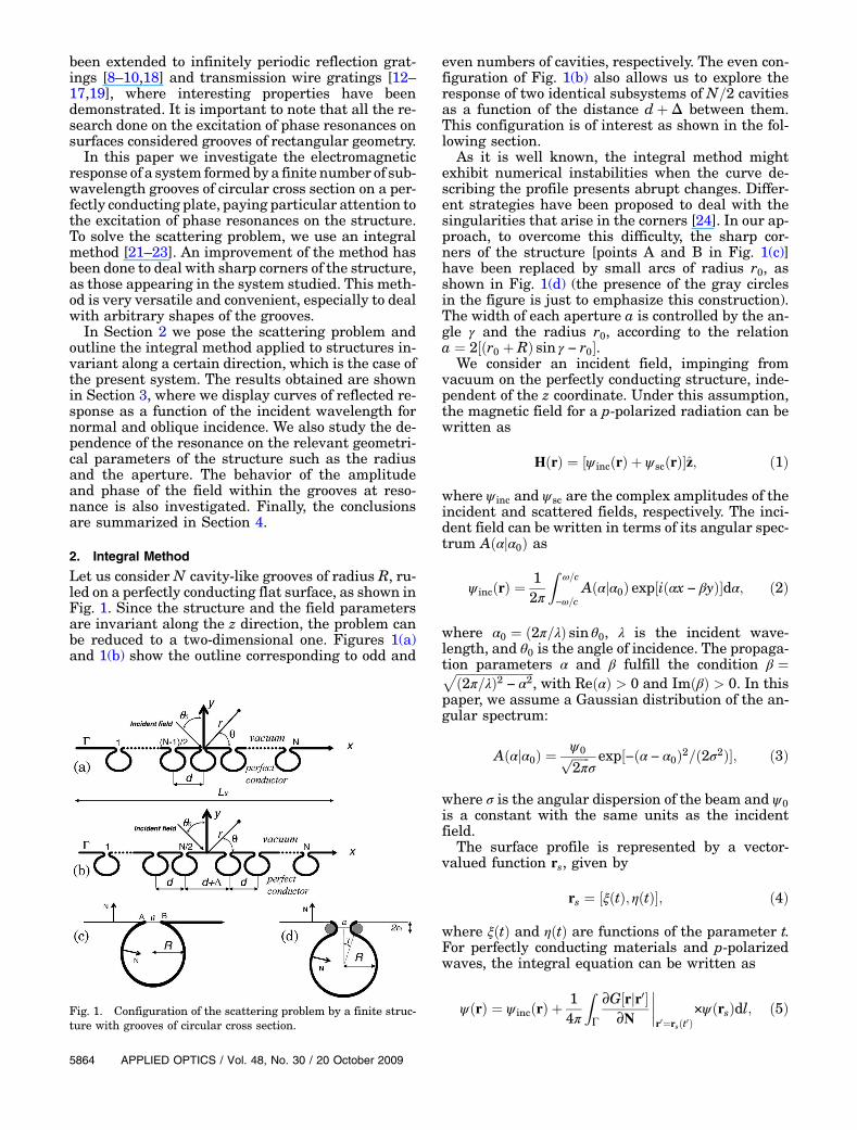
Let us consider N cavity-like grooves of radius R, ru-led on a perfectly conducting flat surface, as shown inFig. 1. Since the structure and the field parametersare invariant along the z direction, the problem canbe reduced to a two-dimensional one. Figures 1(a)and 1(b) show the outline corresponding to odd and
even numbers of cavities, respectively. The even con-figuration of Fig. 1(b) also allows us to explore theresponse of two identical subsystems of N=2 cavitiesas a function of the distance dþΔ between them.This configuration is of interest as shown in the fol-lowing section.
As it is well known, the integral method mightexhibit numerical instabilities when the curve de-scribing the profile presents abrupt changes. Differ-ent strategies have been proposed to deal with thesingularities that arise in the corners [24]. In our ap-proach, to overcome this difficulty, the sharp cor-ners of the structure [points A and B in Fig. 1(c)]have been replaced by small arcs of radius r0, asshown in Fig. 1(d) (the presence of the gray circlesin the figure is just to emphasize this construction).The width of each aperture a is controlled by the an-gle γ and the radius r0, according to the relationa ¼ 2½ðr0 þ RÞ sin γ − r0�.
We consider an incident field, impinging fromvacuum on the perfectly conducting structure, inde-pendent of the z coordinate. Under this assumption,the magnetic field for a p-polarized radiation can bewritten as
HðrÞ ¼ ½ψ incðrÞ þ ψscðrÞ�z; ð1Þ
where ψ inc and ψsc are the complex amplitudes of theincident and scattered fields, respectively. The inci-dent field can be written in terms of its angular spec-trum Aðαjα0Þ as
ψ incðrÞ ¼12π
Z ω=c
−ω=cAðαjα0Þ exp½iðαx − βyÞ�dα; ð2Þ
where α0 ¼ ð2π=λÞ sin θ0, λ is the incident wave-length, and θ0 is the angle of incidence. The propaga-tion parameters α and β fulfill the condition β ¼ffiffiffiffiffiffiffiffiffiffiffiffiffiffiffiffiffiffiffiffiffiffiffiffiffiffi
ð2π=λÞ2 − α2p
, with ReðαÞ > 0 and ImðβÞ > 0. In thispaper, we assume a Gaussian distribution of the an-gular spectrum:
Aðαjα0Þ ¼ψ0ffiffiffiffiffiffi2π
pσexp½−ðα − α0Þ2=ð2σ2Þ�; ð3Þ
where σ is the angular dispersion of the beam and ψ0is a constant with the same units as the incidentfield.
The surface profile is represented by a vector-valued function rs, given by
rs ¼ ½ξðtÞ; ηðtÞ�; ð4Þ
where ξðtÞ and ηðtÞ are functions of the parameter t.For perfectly conducting materials and p-polarizedwaves, the integral equation can be written as
ψðrÞ ¼ ψ incðrÞ þ14π
ZΓ
∂G½rjr0�∂N
����r0¼rsðt0Þ
×ψðrsÞdl; ð5ÞFig. 1. Configuration of the scattering problem by a finite struc-ture with grooves of circular cross section.
5864 APPLIED OPTICS / Vol. 48, No. 30 / 20 October 2009

where ψ is the complex amplitude of the magneticfield, N ¼ −ðdη=dtÞxþ ðdξ=dtÞy is a vector normalto the surface [see Fig. 1(c)], and dl is a differentialof arc on the profile Γ. The Green function G in thekernel of the integral can be expressed in terms of theHankel function of the first kind and order zero:Gðrjr0Þ ¼ iπHð1Þ
0 ½ð2π=λÞjr − r0j�. To obtain the sourcefunctions ψðrsÞ from Eq. (5), it is assumed that theobservation point r is on the profile Γ:
ψðtÞ ¼ ψðtÞinc þ14π limτ→0
ZΓ
∂G½rþs jr0�∂N
����r0¼rsðt0Þ
×ψðt0Þdt0;
ð6Þ
where rþs ¼ rsðtÞ þ τN. Once the source functionshave been determined, ψ sc can be evaluated as
ψscðrÞ ¼i4
ZΓð2π=λÞN · uðtÞHð1Þ
1 ½ð2π=λÞjuðtÞj� × ψðtÞdt;ð7Þ
where uðtÞ ¼ r − rsðtÞ, andHð1Þ1 is the Hankel function
of the first kind and order one. At this stage, it is con-venient to express the observation point r in polarcoordinates r and θ. With this in mind, we can writeEq. (7) in terms of outgoing waves as
ψscðr; θÞ ¼ expðiπ=4Þ exp½ið2π=λÞr�½16π2r=λ�1=2 RðθÞ; ð8Þ
where the scattering amplitude is
RðθÞ ¼ iZΓð2π=λÞ½η0ðt0Þ cos θ
− ξ0ðt0Þ sin θ�ψðt0Þ expf−ið2π=λÞ½ξðt0Þ cos θþ ηðt0Þ sin θ�gdt0: ð9Þ
In writing Eq. (8) we have used the expansion ofHankel functions for large arguments [25] and theapproximation juj ≈ r − ðξðtÞ cosðθÞ þ ηðtÞ sin θÞ forthe argument of the exponential.The radial component of the time-averaged Poynt-
ing vector can be written as
ðSscÞr ¼ ðc=ð8πÞℜ½Esc ×H�sc�Þr
¼ cλð16π2Þℜ
�iψsc
�∂ψsc
∂r
���; ð10Þ
where c is the speed of light in vacuum.We define thefar field intensity scattered at the angle θ as anamount proportional to ðSscÞr:
Intensity∼ ðSscÞr: ð11Þ
The numerical solution of Eq. (6) requires a discre-tization procedure, i.e., the continuous parameter t isreplaced by a set of N elements ½t1;…; tN �. Therefore,Eq. (6) becomes a matrix equation:
ψðtmÞ ¼ ψ incðtmÞ þXn¼N
n¼1
HmnψðtnÞ: ð12Þ
The matrix elements Hmn can be written as [23]
Hmn ¼
8>>><>>>:
iπΔtn2λ f−η0numn þ ξ0nwmngHð1Þ
1 ð2πλ fu2mnþw2
mng1=2Þfu2
mnþw2mng1=2 ; m ≠ n;
12 þ Δtm
4πϕ2ðtmÞ ½ξ0mη00m − ξ00mη0m�; m ¼ n;
ð13Þ
where Δtn ¼ tn − tn−1 is the length of the samplingintervals, ξ0m ¼ ½dξ=dt�ðtmÞ, ξ00m ¼ ½d2ξ=dt2�ðtmÞ, η0m ¼½dξ=dt�ðtmÞ, η00m ¼ ½d2ξ=dt2�ðtmÞ, umn ¼ ξm − ξn, andwmn ¼ ηm − ηn.
Numerical tests were initially performed with theprofile shown in Fig. 1(c). The abrupt change of thisprofile (and of its normal derivative) at points A andB produces numerical instabilities that make itdifficult to achieve convergence of the results. For in-stance, in certain wavelength ranges the field inten-sity shows significant variations when the parameterN is slightly changed. To overcome this problem, thehard edges of the cavities were rounded as shown inFig. 1(d). In contrast with the geometry of Fig. 1(c),numerical tests with the profile of Fig. 1(d) showedvery good convergence of the results as a functionof the parameterN. The curves presented in the nextsection were obtained by taking N ≈ 1300.
3. Results
When the incident wavelength considerably exceedsthe dimensions of the structure, phase resonancescan be excited [20]. Our purpose is to investigatethe phase resonances that appear in a perfectly con-ducting surface with a finite number of cylindricalgrooves, their properties, and their dependence withthe geometrical parameters. In Fig. 2 we analyzethe dependence of the resonances on the number of
20 October 2009 / Vol. 48, No. 30 / APPLIED OPTICS 5865

grooves. We consider grooves of circular cross sectionwith an aperture a=R ¼ 0:02826, separated a dis-tance d ¼ 2:1R, and study the specularly reflected re-sponse for a normally incident p-polarized Gaussianbeam of spatial width W ¼ 20R as a function ofkR. In the range of kR considered, the curves forone and two grooves exhibit a minimum, which isassociated with the so called H00 mode [26] [seeFigs. 2(a) and 2(b)]. From the mathematical pointof view, this low-frequency resonance has a singularnature. The eigenmodes of a perfectly conducting wa-veguide with circular cross section for p polarizationinclude the zero as its lowest eigenfrequency, butsince its associated eigenfunction is identically equalto zero, this is not a true eigenvalue. The effect of cut-ting the cylinder and making an aperture is to shiftthis zero pseudo-eigenvalue by a small complex num-ber with a corresponding nonzero eigenfunction. Interms of an equivalent circuit, the aperture causesa break in the transverse current on the cylinder,which results in an equivalent capacitance and in-ductance that produce the resonance [27]. The fre-quency at which this resonance occurs increaseswith the aperture size [28], and in this case is foundapproximately at kR ¼ 0:22. Although the minimumin the reflected response associated to the H00 modestays for an arbitrary number of grooves, a sharppeak appears in the reflected response for the
three-groove case at kR ¼ 0:2285, as observed inFig. 2(c). This peak corresponds to the so called π re-sonance, and arises from the resonant coupling of theelectromagnetic field within adjacent grooves, as itwas already observed for grooves of rectangular crosssection [7]. For this particular wavelength, the fieldphases in adjacent grooves are opposite to eachother, and this produces a reflectance maximum.In Fig. 3(a) we show the magnitude of the magneticfield at the center of each groove as a function of kR,for the case of three grooves considered in Fig. 2. Inthis figure, the labels L, C, and R correspond to left,central, and right grooves, respectively. A remark-able intensification of the interior field is obtainedat the π resonance. The phase difference betweenthe magnetic fields at the center of adjacent groovesis shown in Fig. 3(b). Notice that due to the symmetryimposed by the normal incidence, both externalgrooves have the same field, and then the phase dif-ference between the right and the central groove isthe same as that between the left and the centralone. This phase difference curve confirms that theπ resonance is associated with a phase differenceof π radians between the magnetic fields at adjacentgrooves. If we keep increasing the number of groovesin the surface, we obtain the curves in Figs. 2(d)–2(f):for five and six grooves there are two maxima withinthe same waveguide resonance minimum, and for
Fig. 2. Reflected intensity as a function of kR for a p-polarized Gaussian beam of width W ¼ 20R normally incident on a finite gratingwith an aperture a=R ¼ 0:02826; the distance between adjacent grooves is d ¼ 2:1R. (a) N ¼ 1, (b) N ¼ 2, (c) N ¼ 3, (d) N ¼ 5, (e) N ¼ 6,(f) N ¼ 7.
5866 APPLIED OPTICS / Vol. 48, No. 30 / 20 October 2009

seven grooves, even one more peak appears. Thistrend is to be expected, and the same behavior wasfound in surfaces with rectangular grooves [7]. Theappearance of more peaks is related to the increasein the number of possibilities to get opposite phasesin adjacent grooves. In the case of three grooves un-der normal incidence, the only possibility is to havethe same phase at the external grooves, opposite tothe central one. Such a phase pattern is also denotedas (þ-þ) according to the terminology already used inthe literature [7,12,17]. For five grooves, more phaseconfigurations could be found, such as (þ - þ - þ),(þ - - - þ), and (þ þ - þ þ). The highest qualitypeak corresponds to the π resonance (opposite phasesin any pair of adjacent grooves), whereas for theother modes the quality slightly decreases. In allcases, the π resonance is located at the largest valueof kR among all the phase resonance modes, as ob-served in the rectangular grooves case [7]. It is inter-esting to notice that in the case of six grooves, thereare also two peaks as in the five-groove case, but theresonances have less quality. This occurs since, even
though in the six-groove case there are also threepossibilities of phase distributions, namely,(þ - þ þ - þ), (þ þ - - þ þ), and (þ - - - - þ), noneof them has opposite phases in every pair of adjacentgrooves, as required for the π resonance, since thissituation is forbidden due to the symmetry imposedby the normally incident plane wave.
The amplitude and phase of the magnetic interiorfield for the five-groove case is shown in Fig. 4. Inthese figures, the labels LL and RR correspond toleftmost and rightmost grooves, respectively, the Land R labels correspond to the grooves at the leftand right of the central one, respectively, and Ccorresponds to the central groove. According toFigs. 4(d) and 4(e), the resonance at kR ≈ 0:229 corre-sponds to the π mode (þ - þ - þ), and that at kR ≈
0:223 corresponds to the mode (þ - - - þ). It can beobserved in Figs. 4(a)–4(c) that the field within allthe grooves is significantly enhanced at the π reso-nance, and at the other mode the field is intensifiedin the external and the central grooves only. This is acharacteristic of phase resonances, as previouslyobserved for other systems [7,20].
When the incidence is no longer normal, new phaseconfigurations are allowed, and then more resonantpeaks may appear in the reflected response. An ex-ample of this is shown in Fig. 5, where we showthe reflected intensity and the phase and magnitudeof the magnetic field within the rulings for a two-groove structure with the same parameters consid-ered in Fig. 2, and for oblique incidence, θ0 ¼ 40°.A resonant peak that was not present in the normalincidence case (included in this figure for compari-son) appears, and, as can be learned from Fig. 5(b),it roughly corresponds to a (þ -) mode, which is a for-bidden mode for normal incidence due to symmetryreasons. At this resonance, the magnetic field withinboth grooves is significantly enhanced, as observed inFigs. 5(c) and 5(d) (the reflected response for thesame structure under normal illumination is also in-cluded for comparison).
In Fig. 6 we analyze the influence of the aperturesize on the reflected response, and, in particular,on the π resonance for the three-groove case. Fourvalues of the aperture have been considered, andthe corresponding intensity curves are shown inFig. 6(a). It can be observed that as the aperture de-creases, the resonant value of kR also decreases, as isexpected for theH00 mode in a slotted cylinder [28]. Ashift in the resonant frequencies of an open cavitywhen varying its aperture size is a general character-istic of cavity resonances; the case of bottle-shapedcavities was investigated in [29,30]. As the aperturedecreases, the resonances become more localized,and their widths also decrease. The possibility of tun-ing the frequency by varying the aperture size is aninteresting characteristic of phase resonances, whichsuggests that these systems could be used as fre-quency selective devices. The resonant frequency asa function of the normalized aperture size is shown inFig. 6(b). This curve shows that for variations of the
Fig. 3. Magnetic field at the center of each groove as a function ofkR for the three-groove case considered in Fig. 2(c). (a) jHj2,(b) phase difference between the external and the central grooves.
20 October 2009 / Vol. 48, No. 30 / APPLIED OPTICS 5867

aperture size within 10% of the radius R, the reso-nant kR varies significantly, and this confirms thetunability of the system.In Fig. 7 we analyze a structure comprising six
grooves, forming two subsets of three grooves each,separated a distance D ¼ dþΔ. We show the re-flected intensity as a function of kR for different ra-tiosΔ=R between 0 and 6. ForΔ=R ¼ 0, the structureis the regular six-groove surface already consideredin Fig. 2(e), in which all the grooves are equallyspaced. Its response is represented by the thick solidline in Fig. 7, where two phase resonances are iden-tified: the highest quality resonance at kR ¼ 0:228,which in the six-groove case corresponds to the(þ - þ þ - þ ) mode, and the (þ þ - - þ þ) mode
at kR ¼ 0:22. As the distance between both three-groove groups is increased, the π resonance peak ispresent in all the reflected spectra, whereas the left-most resonance peak weakens, and for Δ=R ¼ 6almost vanishes. This behavior can be explained interms of the electromagnetic coupling between adja-cent grooves. When the grooves are equally spaced,several possibilities of exciting phase resonancesare allowed, as discussed above in connection toFig. 2. However, asΔ increases, the coupling betweenboth central grooves becomes weaker, and in the lim-it of very large Δ the system behaves like two non-interacting subsets of three grooves. Thus only themodes corresponding to each one of the three-groovesubsets can be excited, which in the normal incidence
Fig. 4. Magnetic field at the center of each groove as a function of kR for the five-groove case considered in Fig. 2(d). (a) jHj2 in the leftmostgroove, (b) jHj2 in the second groove, (c) jHj2 in the central groove, (d) phase difference between the leftmost and the central groove,(e) phase difference between the second and the central groove.
5868 APPLIED OPTICS / Vol. 48, No. 30 / 20 October 2009

case is only the (þ - þ) mode, represented by thenarrow peak at kR ¼ 0:228. The response of a struc-ture with just three equally spaced grooves is also in-cluded for comparison (circles), where it is evidentthat only the π resonance is present.
Fig. 7. Reflected intensity as a function of kR for a p-polarizedGaussian beam of width W ¼ 20R, normally incident on a struc-ture comprising six grooves, forming two subsets of three groovesof aperture a=R ¼ 0:02826 and d ¼ 2:1R each, separated a dis-tance D ¼ dþΔ. The different curves correspond to differentratios Δ=R.
Fig. 5. (a) Reflected intensity as a function of kR for a p-polarized Gaussian beam of widthW ¼ 20R, incident with an angle θ0 ¼ 40°, on atwo-groove grating with an aperture a=R ¼ 0:02826 and distance between grooves of d ¼ 2:1R; (b) phase difference between the magneticfield at the center of each groove in the same case; (c)
��H��2 at the center of the left groove; (d)��H��2 at the center of the right groove.
Fig. 6. Dependence of the resonant kR value on the aperture sizefor the three-groove case considered in the previous figures. (a) Re-flected intensity as a function of kR for several values of the aper-ture; (b) resonant kR as a function of the normalized aperture size.
20 October 2009 / Vol. 48, No. 30 / APPLIED OPTICS 5869
4. Conclusions
We have investigated the electromagnetic responseof finite arrays of subwavelength grooves of circularcross section, and found that phase resonances canbe excited for particular wavelengths. The integralmethod has been developed and applied to solvethe scattering problem, and special attention waspaid to the treatment of sharp boundaries. The exci-tation of phase resonances in this system has beenstudied, and the dependence of their spectral loca-tion with the number of grooves and with the aper-ture size has been analyzed for potential applicationssuch as frequency selectors and polarizers. The mag-netic field within the grooves was also calculated,and the results confirm that phase resonances arecharacterized by a significant enhancement of the in-terior field. This work constitutes the first study ofphase resonances in finite gratings with nonrectan-gular geometry.
The authors gratefully acknowledge partial sup-port from Consejo Nacional de InvestigacionesCientíficas y Técnicas (CONICET), Universidad deBuenos Aires (UBA), Agencia Nacional de PromociónCientífica y Tecnológica (ANPCYT-BID 1728/OC-AR06-01785), and Programa de Movilidad Académi-ca de la Universidad Autónoma de Baja California(UABC), 6ta Convocatoria.
References1. E. Goulielmakis, G. Nersisyan, N. Papadogiannis,
D. Charalambidis, G. Tsakiris, and K. Witte, “A dispersionlessMichelson interferometer for the characterization of atto-second pulses,” Appl. Phys. B 74, 197–206 (2002).
2. J. J. Wang, F. Liu, X. Deng, X. Liu, L. Chen, P. Sciortino, andR. Varghese, “Monolithically integrated circular polarizerswith two-layer nano-gratings fabricated by imprint lithogra-phy,” J. Vac. Sci. Technol. B 23, 3164–3167 (2005).
3. T. W. Ebbesen, H. J. Lezec, H. F. Ghaemi, T. Thio, andP. A. Wolff, “Extraordinary optical transmission throughsub-wavelength hole arrays,” Nature 391, 667–669 (1998).
4. H. F. Ghaemi, T. Thio, D. E. Grupp, T. W. Ebbesen, andH. J. Lezec, “Surface plasmons enhance optical transmissionthrough subwavelength holes,” Phys. Rev. B 58, 6779–6782(1998).
5. J. A. Porto, F. J. García-Vidal, and J. B. Pendry, “Transmissionresonances on metallic gratings with very narrow slits,” Phys.Rev. Lett. 83, 2845–2848 (1999).
6. F. J. García-Vidal and L. Martín-Moreno, “Transmission andfocusing of light in one-dimensional periodically nanostruc-tures metals,” Phys. Rev. B 66, 155412 (2002).
7. D. C. Skigin, V. V. Veremey, and R. Mittra, “Superdirective ra-diation from finite gratings of rectangular grooves,” IEEETrans. Antennas Propag. 47, 376–383 (1999).
8. A. N. Fantino, S. I. Grosz, and D. C. Skigin, “Resonant effect inperiodic gratings comprising a finite number of grooves ineach period,” Phys. Rev. E 64, 016605 (2001).
9. S. I. Grosz, D. C. Skigin, and A. N. Fantino, “Resonant effectsin compound diffraction gratings: influence of the geometricalparameters of the surface,” Phys. Rev. E 65, 056619 (2002).
10. D. C. Skigin, A. N. Fantino, and S. I. Grosz, “Phase resonancesin compound metallic gratings,” J. Opt. A Pure Appl. Opt. 5,S129–S135 (2003).
11. J. Le Perchec, P. Quemerais, A. Barbara, and T. Lopez-Rıos,“Controlling strong electromagnetic fields at subwavelengthscales,” Phys. Rev. Lett. 97, 036405 (2006).
12. D. C. Skigin and R. A. Depine, “Transmission resonances onmetallic compound gratings with subwavelength slits,” Phys.Rev. Lett. 95, 217402 (2005).
13. D. C. Skigin and R. A. Depine, “Resonances on metallic com-pound transmission gratings with subwavelength wires andslits,” Opt. Commun. 262, 270–275 (2006).
14. D. C. Skigin and R. A. Depine, “Narrow gaps for transmissionthrough metallic structured gratings with subwavelengthslits,” Phys. Rev. E 74, 046606 (2006).
15. A. P. Hibbins I. R. Hooper, M. J. Lockyear, and J. R. Sambles,“Microwave transmission of a compoundmetal grating,” Phys.Rev. Lett. 96, 257402 (2006).
16. D. C. Skigin, H. Loui, Z. Popovic, and E. Kuester, “Bandwidthcontrol of forbidden transmission gaps in compound struc-tures with subwavelength slits,” Phys. Rev. E 76, 016604(2007).
17. Y. G. Ma, X. S. Rao, G. F. Zhang, and C. K. Ong, “Microwavetransmission modes in compound metallic gratings,” Phys.Rev. B 76, 085413 (2007).
18. A. Barbara, J. Le Perchec, S. Collin, C. Sauvan, J.-L. Pelouard,T. López-Ríos, and P. Quémerais, “Generation and control ofhot spots on commensurate metallic gratings,” Opt. Express16, 19127–19135 (2008).
19. M. Navarro-Cía, D. C. Skigin, M. Beruete, andM. Sorolla, “Ex-perimental demonstration of phase resonances in metalliccompound gratings with subwavelength slits in themillimeterwave regime,” Appl. Phys. Lett. 94, 091107 (2009).
20. V. V. Veremey and R. Mittra, “Scattering from structuresformed by resonant elements,” IEEE Trans. Antennas Propag.46, 494–501 (1998).
21. A. A. Maradudin, T. Michel, A. R. McGurn, and E. R. Méndez,“Enhanced backscattering of light from a random grating,”Ann. Phys. (N.Y.) 203, 255–307 (1990).
22. C. I. Valencia and R. A. Depine, “Resonant scattering of lightby an open cylindrical cavity ruled on a highly conducting flatsurfaces,” Opt. Commun. 159, 254–265 (1999).
23. C. I. Valencia, E. R. Méndez, and B. S. Mendoza, “Second har-monic generation in the scattering of light by two dimensionalparticles,” J. Opt. Soc. Am. B 20, 2150–2161 (2003).
24. R. Goloskie, T. Thio, and L. R. Ram-Mohan, “Boundary ele-ments and surface plasmons,” Comput. Phys. 10, 477–495(1996).
25. M. Abramowitz and I. A. Stegun, Handbook of MathematicalFunctions (Dover, 1970), p. 364.
26. D. Colak, A. I. Nosich, and A. Altintas, “Radar cross-sectionstudy of cylindrical cavity-backed apertures with outer or in-ner material coating: the case of H-polarization,” IEEE Trans.Antennas Propag. 43, 440–447 (1995).
27. R. W. Ziolkowski and J. B. Grant, “Scattering from cavity-backed apertures: the generalized dual series solution ofthe concentrically loaded E-pol slit cylinder problem,” IEEETrans. Antennas Propag. 35, 504–528 (1987).
28. P. M. Goggans and T. H. Shumpert, “Backscatter RCS for TEand TM excitations of dielectric-filled cavity-backed aperturesin two-dimensional bodies,” IEEE Trans. Antennas Propag.39, 1224–1227 (1991).
29. D. C. Skigin and R. A. Depine, “Resonant enhancement of thefield within a single ground-plane cavity: comparison of differ-ent rectangular shapes,” Phys. Rev. E 59, 3661–3668 (1999).
30. D. C. Skigin and R. A. Depine, “Resonant modes of a bottle-shaped cavity and their effects in the response of finite andinfinite gratings,” Phys. Rev. E 61, 4479–4490 (2000).
5870 APPLIED OPTICS / Vol. 48, No. 30 / 20 October 2009