Subwavelength acoustic focusing by surface-wave-resonance ...
10
Subwavelength acoustic focusing by surface-wave-resonance enhanced transmission in doubly negative acoustic metamaterials Xiaoming Zhou, M. Badreddine Assouar, and Mourad Oudich Citation: Journal of Applied Physics 116, 194501 (2014); doi: 10.1063/1.4901996 View online: http://dx.doi.org/10.1063/1.4901996 View Table of Contents: http://scitation.aip.org/content/aip/journal/jap/116/19?ver=pdfcov Published by the AIP Publishing Articles you may be interested in Negative effective mass density of acoustic metamaterial plate decorated with low frequency resonant pillars J. Appl. Phys. 116, 184504 (2014); 10.1063/1.4901462 Achieving selective interrogation and sub-wavelength resolution in thin plates with embedded metamaterial acoustic lenses J. Appl. Phys. 116, 054906 (2014); 10.1063/1.4892017 Experimental study on acoustic subwavelength imaging of holey-structured metamaterials by resonant tunneling J. Acoust. Soc. Am. 135, 1686 (2014); 10.1121/1.4868395 Defect Detection and Imaging Using Focused Ultrasonic Guided Waves AIP Conf. Proc. 894, 185 (2007); 10.1063/1.2717972 Time-reversal focusing of elastic surface waves J. Acoust. Soc. Am. 118, 735 (2005); 10.1121/1.1945468 [This article is copyrighted as indicated in the article. Reuse of AIP content is subject to the terms at: http://scitation.aip.org/termsconditions. Downloaded to ] IP: 219.143.205.99 On: Tue, 18 Nov 2014 05:44:13
-
Upload
khangminh22 -
Category
Documents
-
view
0 -
download
0
Transcript of Subwavelength acoustic focusing by surface-wave-resonance ...
Subwavelength acoustic focusing by surface-wave-resonance enhanced transmissionin doubly negative acoustic metamaterialsXiaoming Zhou, M. Badreddine Assouar, and Mourad Oudich Citation: Journal of Applied Physics 116, 194501 (2014); doi: 10.1063/1.4901996 View online: http://dx.doi.org/10.1063/1.4901996 View Table of Contents: http://scitation.aip.org/content/aip/journal/jap/116/19?ver=pdfcov Published by the AIP Publishing Articles you may be interested in Negative effective mass density of acoustic metamaterial plate decorated with low frequency resonant pillars J. Appl. Phys. 116, 184504 (2014); 10.1063/1.4901462 Achieving selective interrogation and sub-wavelength resolution in thin plates with embedded metamaterialacoustic lenses J. Appl. Phys. 116, 054906 (2014); 10.1063/1.4892017 Experimental study on acoustic subwavelength imaging of holey-structured metamaterials by resonant tunneling J. Acoust. Soc. Am. 135, 1686 (2014); 10.1121/1.4868395 Defect Detection and Imaging Using Focused Ultrasonic Guided Waves AIP Conf. Proc. 894, 185 (2007); 10.1063/1.2717972 Time-reversal focusing of elastic surface waves J. Acoust. Soc. Am. 118, 735 (2005); 10.1121/1.1945468
[This article is copyrighted as indicated in the article. Reuse of AIP content is subject to the terms at: http://scitation.aip.org/termsconditions. Downloaded to ] IP:
219.143.205.99 On: Tue, 18 Nov 2014 05:44:13
Subwavelength acoustic focusing by surface-wave-resonance enhancedtransmission in doubly negative acoustic metamaterials
Xiaoming Zhou,1,2 M. Badreddine Assouar,1,2,a) and Mourad Oudich1,2
1CNRS, Institut Jean Lamour, Vandoeuvre-les-Nancy F-54506, France2Institut Jean Lamour, University of Lorraine, Boulevard des Aiguillettes, BP: 70239,54506 Vandoeuvre-les-Nancy, France
(Received 21 August 2014; accepted 5 November 2014; published online 17 November 2014)
We present analytical and numerical analyses of a yet unseen lensing paradigm that is based on a
solid metamaterial slab in which the wave excitation source is attached. We propose and
demonstrate sub-diffraction-limited acoustic focusing induced by surface resonant states in
doubly negative metamaterials. The enhancement of evanescent waves across the metamaterial
slab produced by their resonant coupling to surface waves is evidenced and quantitatively
determined. The effect of metamaterial parameters on surface states, transmission, and
wavenumber bandwidth is clearly identified. Based on this concept consisting of a wave source
attached on the metamaterial, a high resolution of k/28.4 is obtained with the optimum effective
physical parameters, opening then an exciting way to design acoustic metamaterials for ultrasonic
focused imaging. VC 2014 AIP Publishing LLC. [http://dx.doi.org/10.1063/1.4901996]
I. INTRODUCTION
Focused ultrasound is widely used in medical diagnosis
as a noninvasive and inexpensive method. Suffered, how-
ever, from diffraction of sound, the resolution of a conven-
tional acoustic imaging device is limited to half working
wavelength. A most basic approach to increase the resolution
is to raise the operating frequency, but at the cost of lowering
the penetration depth of ultrasounds. For many decades, it is
highly demanded for the resolution of acoustic focusing to
be improved without the enhancement of operating fre-
quency. The diffraction limit is caused by the absence in the
focusing spot of evanescent waves, which contain deep sub-
wavelength information, due to their rapid decay in the near
field. To break the diffraction limit, it is essential for the lens
system to enhance evanescent wave amplitude. As a newly
emerging field, acoustic metamaterials1,2 (MTMs) are pro-
viding solutions for sub-diffraction-limited resolution by
enhancing evanescent waves.3–5 Designed with the MTM
concept, acoustic hyperlens and superlens are two typical
kinds of imaging devices capable of evanescent wave manip-
ulation. Acoustic hyperlens is termed for metamaterials with
hyperbolic dispersion relation, achieved normally from the
concept of anisotropic dynamic mass density.4–11 The hyper-
lens prevents evanescent waves from decaying by converting
them to propagating waves within the lens, which can then
be transferred to the far side of the lens used for the image
formation. The converting mechanism relies on the flat dis-
persion curve with respect to the parallel momentum due to
extremely anisotropic mass density. The transferring mecha-
nisms discovered so far include the Fabry-P�erot reso-
nance,5,7,8 extraordinary transmission at near-zero mass,10
and the resonant tunneling.9 Besides above features, “far-
field” hyperlens requires additionally the magnifying
mechanism by which evanescent waves become propagating
ones when they cross the lens.4,6,12 The best resolution by
the hyperlens reported in experiment is k/50 (k is the wave-
length).5 Although the hyperlens is capable of enhancing
contrast of subwavelength-size objects from the background,
it lacks the ability of ultrasound focusing.
Acoustic superlens has the ability of ultrasonic subwave-
length focusing, whose idea can be traced back to the
Pendry’s perfect lens in optic superfocusing.13,14 The optic
perfect lens is a MTM flat slab with doubly negative (DNG)
permittivity and permeability. When an optical source is
placed in front of the MTM slab, the emitted propagating
waves can converge on the other side of the MTM slab due to
negative refraction and evanescent waves can be strongly
enhanced by coupling to surface waves supported by MTMs.
Thus, the focus can be as sharp as the source due to both the
convergence of propagating waves and the recovering of
evanescent waves. Acoustic superlens shares the same
physics with the optic one.15 Furthermore, there is an analogy
in the surface wave condition between fluid MTMs with triv-
ial shear modulus and optical ones. In view of biomedical
imaging applications, the structure models of the no-shear
fluid MTMs recently proposed are not suitable for the human
tissue environment, while serve mainly for the air environ-
ment.16–20 In contrast, solid MTMs21 are found to be good
candidates for acoustic wave manipulation in dense liquids,
for example, used for subwavelength focusing in mercury.22
Various structure models of solid metamaterials relying on
the chiral effect or the resonance of multiple inclusions have
been proposed.23–26 It has been demonstrated with numerical
analyses that the solid DNG MTMs23,24 have nearly the water
impedance, and thus are more suitably used in biomedical
environment. The main physical difference between fluid and
solid MTMs is the presence of shear waves for the latter ma-
terial. Up to now, the physics of acoustic focused imaging by
general solid MTMs and the influence of the shear modulus
on the resolution are not clearly discovered.
a)Author to whom correspondence should be addressed. Electronic mail:
0021-8979/2014/116(19)/194501/9/$30.00 VC 2014 AIP Publishing LLC116, 194501-1
JOURNAL OF APPLIED PHYSICS 116, 194501 (2014)
[This article is copyrighted as indicated in the article. Reuse of AIP content is subject to the terms at: http://scitation.aip.org/termsconditions. Downloaded to ] IP:
219.143.205.99 On: Tue, 18 Nov 2014 05:44:13

In this work, we propose and demonstrate analytically
and numerically sub-diffraction-limited acoustic focusing,
induced by surface resonant states of DNG MTMs, with
potential applications to acoustic high-resolution imaging.
Figure 1 illustrates the analyzed model, which consists in a
MTM flat slab of thickness d sandwiched between two dif-
ferent fluid half-spaces. The left half-space is the source
region, where the air environment is considered and a small
ultrasonic transducer would be attached to the MTM surface
in practical application as the wave source. Subwavelength
ultrasound focusing will be generated in the right half-space,
where the water is employed to simulate the human tissue
environment due to their similar acoustic characteristics. In
Sec. II, we analyze surface wave conditions for the special
case of no-shear fluid MTMs, for later comparison study
with the general solid ones. In the Secs. III and IV, surface
wave conditions and wave propagation characteristics of
solid MTMs will be analyzed, and the influence of the
MTM’s parameters on surface states and transmission will
be studied. High-resolution acoustic focusing by solid
MTMs will be designed and verified by full-wave numerical
simulation in Sec. V.
II. SURFACE RESONANT STATES IN NO-SHEAR FLUIDMETAMATERIALS
Assume the mass density q and bulk modulus j for the
fluid MTM, both of which can be negative values. The mass
density and sound velocity are, respectively, qA¼ 1.25 kg/m3
and cA¼ 343 m/s for the air, and qW¼ 1000 kg/m3 and
cW¼ 1490 m/s for the water. Their bulk modulus can be
computed by jA ¼ qAc2A and jW ¼ qWc2
W . Without loss of
generality, we assume two-dimensional scenario in which
wave fields depend only on the propagation direction x and
one transverse coordinate y. Let us seek conditions for sur-
face waves existing at interfaces between MTMs and fluids.
The criterion for surface waves is that the wave fields decay
exponentially in the direction perpendicular to the interface.
Thereby, the pressure p and displacement field u in the direc-
tion x for each region of the system can be written as
p ¼ a1eqAxeiksy; (1)
u ¼ qA
qAx2a1eqAxeiksy; (2)
for the region x � 0,
p ¼ ðb1e�qFx þ b2eqFxÞeiksy; (3)
u ¼ qF
qx2�b1e�qFx þ b2eqFxð Þeiksy; (4)
for the region 0 � x � d, and
p ¼ a2e�qWðx�dÞeiksy; (5)
u ¼ �qW
qWx2a2e�qW x�dð Þeiksy; (6)
for the region x � d, where ks is the wave number of the sur-
face wave to be determined. The wave numbers of evanes-
cent waves in the air, the water, and the fluid MTMs are,
respectively, qA ¼ffiffiffiffiffiffiffiffiffiffiffiffiffiffiffiffiffiffiffiffiffiffiffik2
s � x2=c2A
p, qW ¼
ffiffiffiffiffiffiffiffiffiffiffiffiffiffiffiffiffiffiffiffiffiffiffiffik2
s � x2=c2W
p, and
qF ¼ffiffiffiffiffiffiffiffiffiffiffiffiffiffiffiffiffiffiffiffiffiffiffiffik2
s � x2q=jp
. The time harmonics exp(�ixt) has
been assumed. Continuous conditions of pressures and dis-
placements at interfaces x¼ 0 and x¼ d result in four equa-
tions for the constants a1, b1, b2, and a2. A nontrivial
solution of these equations exists if the determinant of the
coefficients of four constants vanishes, which yields the fol-
lowing dispersion equation:
qA
qA
qW
qW
1þ Q2F
� �þ qF
q1 – Q2
F
� �� �
þ qqF
qW
qW
1 – Q2F
� �þ qF
q1þ Q2
F
� �� �¼ 0; (7)
where QF ¼ e�qFd .
Let us first visit two special cases. When the two half-
spaces are both water, the dispersion equation for the water/
MTM/water system is
qW
qW
1 6 QFð Þ þ qF
q1 7 QFð Þ ¼ 0: (8)
When the infinite thickness of the metamaterial slab, i.e.,
QF � 1, is considered in Eq. (8), which means the decou-
pling between two interfaces, the dispersion equation for the
MTM/water system becomes15
qW
qW
þ qF
q¼ 0: (9)
For the studied model, where the left half-space is air and the
right one is water, a reasonable simplification can be made
for Eq. (7) based on the fact that qA� jqj, qW. Thereby, the
first term in Eq. (7) can be neglected, resulting in a more
simple form
qW
qW
1 – Q2F
� �þ qF
q1þ Q2
F
� �¼ 0: (10)
This simplification is equivalent to the traction-free bound-
ary condition p¼ 0 imposed at the interface x¼ 0. Such con-
dition together with continuous conditions of pressures and
displacements at interface x¼ d lead to three equations for
the constants b1, b2, and a2. The vanishing determinant of
the corresponding coefficient matrix yields the same result to
Eq. (10).FIG. 1. Schematic view of the lensing model made up of a MTM flat slab in
which the wave excitation source is attached.
194501-2 Zhou, Badreddine Assouar, and Oudich J. Appl. Phys. 116, 194501 (2014)
[This article is copyrighted as indicated in the article. Reuse of AIP content is subject to the terms at: http://scitation.aip.org/termsconditions. Downloaded to ] IP:
219.143.205.99 On: Tue, 18 Nov 2014 05:44:13
For the existence of surface waves, it is required that
k2s > x2=c2
W and k2s > x2q=j, which means qW, qF> 0 and
0<QF< 1. Then, the necessary condition for the presence
of surface waves is the negative density (q < 0) of MTMs,
which is true for the water/MTM/water, MTM/water, and
air/MTM/water systems, as verified by Eqs. (8), (9), and
(10), respectively. For the studied model, the condition k2s >
x2=c2A is not necessary. Without this condition, surface
waves exist only at the MTM-water interface, instead of the
air-MTM one.
For plane acoustic waves with parallel wave number ky
incident leftwards on the MTM slab, the pressure and dis-
placement field in each region of the system are expressed
as
p ¼ ðA0eikAx þ A1e�ikAxÞeikyy; (11)
u ¼ ikA
qAx2A0eikAx � A1e�ikAx� �
eikyy; (12)
for the region x � 0,
p ¼ ðB1eikFx þ B2e�ikFxÞeikyy; (13)
u ¼ ikF
qx2B1eikFx � B2e�ikFx� �
eikyy; (14)
for the region 0 � x � d, and
p ¼ A2eikWðx�dÞeikyy; (15)
u ¼ ikW
qWx2A2eikW x�dð Þeikyy; (16)
for the region x � d, where kA ¼ffiffiffiffiffiffiffiffiffiffiffiffiffiffiffiffiffiffiffiffiffiffiffix2=c2
A � k2y
q,
kW ¼ffiffiffiffiffiffiffiffiffiffiffiffiffiffiffiffiffiffiffiffiffiffiffiffix2=c2
W � k2y
q, and kF ¼
ffiffiffiffiffiffiffiffiffiffiffiffiffiffiffiffiffiffiffiffiffiffiffiffix2q=j� k2
y
q. By use of
continuous boundary conditions, transmission coefficients
T ¼ A2=A0 are derived to be
T ¼ 4eikFd
qA
kA
kW
qW
1þ e2ikFdð Þ þ kF
q1–e2ikFdð Þ
� �þ q
kF
kW
qW
1 – e2ikFdð Þ þ kF
q1þ e2ikFdð Þ
� � : (17)
By comparison of Eqs. (7) and (17), it is readily found that
the denominator of Eq. (17) vanishes when the parallel
wavenumber of incident waves ky matches the wavenumber
ks of surface waves. Transmission coefficients reach infinity
in this case, meaning that evanescent waves can be reso-
nantly enhanced in amplitudes when they cross the MTM
slab. This is the main idea for superlens to achieve acoustic
subwavelength focusing beyond the diffraction limit. For
three systems mentioned above, there all exist the perfect
imaging condition, i.e., q¼�qW and j¼�jW, which means
that any value of ks is solution of dispersion equations.
Therefore, perfect focusing is expected from this condition,
as all components of evanescent waves can be recovered by
coupling to surface waves of MTMs.
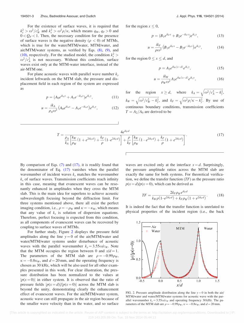
For further study, Figure 2 displays the pressure field
amplitudes along the line y¼ 0 of the air/MTM/water and
water/MTM/water systems under disturbance of acoustic
waves with the parallel wavenumber ky¼ 3.55x/cW. Note
that the MTM occupies the region between 0 and x/d¼ 1.
The parameters of the MTM slab are q¼�0.99qW,
j¼�0.8jW, and d¼ 20 mm, and the operating frequency is
chosen as 30 kHz, which will be also used for all other exam-
ples presented in this work. For clear illustration, the pres-
sure distribution has been normalized to the values at
jp(x¼ 0)j in either system. It is observed that the ratio of
pressure fields jp(x¼ d)j/jp(x¼ 0)j across the MTM slab is
beyond the unity, demonstrating clearly the enhancement
effect of evanescent waves. For the air/MTM/water system,
acoustic wave can still propagate in the air region because of
the smaller wave velocity than in the water, and so surface
waves are excited only at the interface x¼ d. Surprisingly,
the pressure amplitude ratios across the MTM slab are
exactly the same for both systems. For theoretical verifica-
tion, we define the transfer function (TF) as the pressure ratio
p(x¼ d)/p(x¼ 0), which can be derived as
TF ¼ 2kFqWeikFd
kWq 1–e2ikFdð Þ þ kFqW 1þ e2ikFdð Þ : (18)
It is indeed the fact that the transfer function is unrelated to
physical properties of the incident region (i.e., the back
FIG. 2. Pressure amplitude distribution along the line y¼ 0 in both the air/
MTM/water and water/MTM/water systems for acoustic wave with the par-
allel wavenumber ky¼ 3.55x/cW and operating frequency 30 kHz. The pa-
rameters of the MTM slab are q¼�0.99qW, j¼�0.8jW, and d¼ 20 mm.
194501-3 Zhou, Badreddine Assouar, and Oudich J. Appl. Phys. 116, 194501 (2014)
[This article is copyrighted as indicated in the article. Reuse of AIP content is subject to the terms at: http://scitation.aip.org/termsconditions. Downloaded to ] IP:
219.143.205.99 On: Tue, 18 Nov 2014 05:44:13
medium). This also reveals the superiority of the proposed
superlens model, in that the enhancement effect of evanes-
cent waves is invariant to the back medium when the source
is attached to the MTM surface. After a clear understanding
of the surface resonant states and associated enhancement
effect in the fluid MTM case, we will examine in Sec. III the
surface states enabled by solid MTMs.
III. SURFACE RESONANT STATES IN SOLIDMETAMATERIALS
We assume that the solid MTM is characterized by mass
density q and Lam�e coefficients k and l. Following the crite-
rion for surface waves, the displacement in the direction x,
the normal and shear stresses in the MTM region are
expressed, respectively, as
u ¼ iqL
ksb1e�qLx þ iks
qTb2e�qT x � iqL
ksb3eqLx � iks
qTb4eqT x
� �eiksy; (19)
rxx ¼ ikks � i kþ 2lð Þ q2L
ks
� �b1e�qLx þ b3eqLxð Þ � 2ilks b2e�qT x þ b4eqT xð Þ
eiksy; (20)
rxy ¼ 2lqL �b1e�qLx þ b3eqLxð Þ þ l qT þk2
s
qT
!�b2e�qT x þ b4eqT xð Þ
" #eiksy; (21)
where qL ¼ffiffiffiffiffiffiffiffiffiffiffiffiffiffiffiffiffiffiffiffiffiffiffiffiffiffiffiffiffiffiffiffiffiffiffiffiffiffik2
s � x2q=ðkþ 2lÞp
and qT ¼ffiffiffiffiffiffiffiffiffiffiffiffiffiffiffiffiffiffiffiffiffiffiffiffik2
s � x2q=lp
are, respectively, wave numbers of longitudinal and trans-
verse evanescent waves in the solid MTMs. For the studied
model, one can get five equations for the constants b1, b2, b3,
b4, and a2 by using the traction-free boundary condition,
namely rxx¼rxy¼ 0, at the interface x¼ 0, in conjunction
with continuous conditions of normal stress and displace-
ments as well as the zero-shear-stress condition at interface
x¼ d. The dispersion equation of surface waves can be
obtained by the vanishing determinant of the corresponding
coefficient matrix. The dispersion relation is too tedious to
be shown here. However, there exists an efficient simplifica-
tion, as will be presented below.
To proceed, the dispersion equation for the MTM/water
system will be given first. The stress and displacement fields
in the MTM half-space are written as
u ¼ � iqL
ksb1eqLx � iks
qTb2eqT x
� �eiksy; (22)
rxx ¼ ikks � i kþ 2lð Þ q2L
ks
� �b1eqLx � 2ilksb2eqT x
eiksy;
(23)
rxy ¼ 2lqLb1eqLx þ l qT þk2
s
qT
!b2eqT x
" #eiksy: (24)
Consider the fluid-solid interfacial conditions by use of Eqs.
(5), (6), and (22)–(24). The dispersion equation of surface
waves for the MTM/water system is
qWqL þ qqW ¼2lqWk2
s
x2þ 2qWqLk2
s
q2T þ k2
s
1� 2lqTqW
qWx2
� �: (25)
Note first that the dispersion equation (9) of the fluid MTM/
water system can be recovered from Eq. (25) with the param-
eter l¼ 0. To examine the effect of the shear modulus, we
assume equal longitudinal wave velocities for the MTM and
water, namely (kþ 2l)/q¼ jW/qW, which means qL¼ qW.
When l are very small nonzero values, the right-hand side of
Eq. (25) must be positive, meaning that qþqW> 0.
qþ qW¼ 0 is unachievable, since Eq. (25) becomes qT¼ qW
in this case, which is never satisfied. To quantify the range
of values of l, we consider the special case where the second
term in the right-hand side of Eq. (25) vanishes, i.e.,
qWx2 � 2lqTqW ¼ 0: (26)
Equation (25) then becomes
qWqL þ qqW ¼2lqWk2
s
x2: (27)
By combining Eqs. (26) and (27), we get a simple expression
for the shear modulus
l ¼ jW
4 d2 � 1ð Þ ; (28)
where we have defined the normalized wavenumber d as
d¼ ks/(x/cW). As an example of a moderate value d¼ 5, we
can deduce from Eq. (28) that the shear modulus of the
MTM is approximately a hundred times lower than the mod-
ulus of the water, l ¼ jW/96. There is no special meaning
for the condition in Eq. (26); in this example, Eq. (26) means
the MTM density �739.6 kg/m3, Eq. (28) reads an important
conclusion: high wavenumbers of surface waves are avail-
able in the low-shear-modulus (LSM) medium. Note that
jkj � jW in the LSM case; then, the LSM approximation
means l� jkj for high values of d. In order for further veri-
fication of LSM approximation, Figure 3 displays the values
of d at various shear modulus l of the MTM slab with thick-
nesses d¼ 20 mm and d¼ 10 mm for both air/MTM/water
and MTM/water systems. Two different MTM densities
q¼�950 and �990 kg/m3 are considered and parameters of
194501-4 Zhou, Badreddine Assouar, and Oudich J. Appl. Phys. 116, 194501 (2014)
[This article is copyrighted as indicated in the article. Reuse of AIP content is subject to the terms at: http://scitation.aip.org/termsconditions. Downloaded to ] IP:
219.143.205.99 On: Tue, 18 Nov 2014 05:44:13
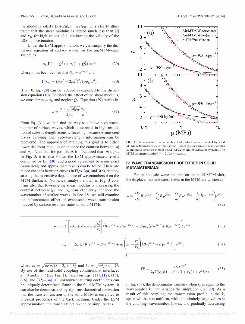
the modulus satisfy (kþ 2l)/q¼ jW/qW. It is clearly illus-
trated that the shear modulus is indeed much less than jkjand jW for high values of d, confirming the validity of the
LSM approximation.
Under the LSM approximation, we can simplify the dis-
persion equation of surface waves for the air/MTM/water
system as
qWCð1� Q2LÞ þ qLð1þ Q2
LÞ ¼ 0; (29)
where it has been defined that QL ¼ e�qLd and
CðksÞ ¼ ðqx2 � 2lk2s Þ
2=ðqqWx4Þ: (30)
If l¼ 0, Eq. (29) can be reduced as expected to the disper-
sion equation (10). To check the effect of the shear modulus,
we consider qL¼ qW and neglect QL. Equation (29) results in
d ¼ qþffiffiffiffiffiffiffiffiffiffiffiffijqjqW
p2qW
jW
l: (31)
From Eq. (31), we can find the way to achieve high wave-
number of surface waves, which is essential in high resolu-
tion of subwavelength acoustic focusing, because evanescent
waves carrying finer sub-wavelength information can be
recovered. The approach of attaining this goal is to either
lower the shear modulus or enhance the contrast between jqjand qW. Note that for positive d, it is required that jqj< qW.
In Fig. 3, it is also shown the LSM-approximated results
computed by Eq. (30) and a good agreement between exact
(numerical) and approximate results can be found. There are
minor changes between curves in Figs. 3(a) and 3(b), demon-
strating the insensitive dependence of wavenumbers d on the
MTM thickness. Numerical analysis shown in Fig. 3 con-
firms also that lowering the shear modulus or increasing the
contrast between jqj and qW can efficiently enhance the
wavenumber of surface waves. In Sec. IV, we will examine
the enhancement effect of evanescent wave transmission
induced by surface resonant states of solid MTMs.
IV. WAVE TRANSMISSION PROPERTIES IN SOLIDMETAMATERIALS
For an acoustic wave incident on the solid MTM slab,
the displacement and stress fields in the MTM are written as
u¼ kL
kyB1eikLx� ky
kTB2eikT x� kL
kyB3e�ikLxþ ky
kTB4e�ikT x
� �eikyy;
(32)
rxx ¼ ikky þ i kþ 2lð Þ k2L
ky
" #B1eikLx þ B3e�ikLx� �
� 2ilky B2eikT x þ B4e�ikT x� �( )
eikyy; (33)
rxy ¼ 2ilkL B1eikLx � B3e�ikLx� �
þ il kT �k2
y
kT
!B2eikT x � B4e�ikT x� �" #
eikyy; (34)
where kL ¼ffiffiffiffiffiffiffiffiffiffiffiffiffiffiffiffiffiffiffiffiffiffiffiffiffiffiffiffiffiffiffiffiffiffiffiffiffiffix2q=ðkþ 2lÞ � k2
s
pand kT ¼
ffiffiffiffiffiffiffiffiffiffiffiffiffiffiffiffiffiffiffiffiffiffiffiffix2q=l� k2
s
p.
By use of the fluid-solid coupling conditions at interfaces
x¼ 0 and x¼ d (see Fig. 1), based on Eqs. (11), (12), (15),
(16), and (32)–(34), all unknown scattering coefficients can
be uniquely determined. Same to the fluid MTM system, it
can also be demonstrated by rigorous theoretical derivation
that the transfer function of the solid MTM is unrelated to
physical properties of the back medium. Under the LSM
approximation, the transfer function can be simplified as
TF ¼ 2kLeikLd
kWC kyð Þ 1� e2ikLdð Þ þ kL 1þ e2ikLdð Þ : (35)
In Eq. (35), the denominator vanishes when ky is equal to the
wavenumber ks that satisfies the simplified Eq. (29). As a
result of this coupling, the transmission profile in the ky
space will be non-uniform, with the infinitely large values at
the coupling wavenumber ky¼ ks, and gradually decreasing
FIG. 3. The normalized wavenumber d of surface waves enabled by solid
MTMs with thicknesses 20 mm (a) and 10 mm (b) for various shear modulus
l, and mass densities in both air/MTM/water and MTM/water systems. The
MTM parameters satisfy (kþ 2l)/q¼jW/qW.
194501-5 Zhou, Badreddine Assouar, and Oudich J. Appl. Phys. 116, 194501 (2014)
[This article is copyrighted as indicated in the article. Reuse of AIP content is subject to the terms at: http://scitation.aip.org/termsconditions. Downloaded to ] IP:
219.143.205.99 On: Tue, 18 Nov 2014 05:44:13

finite values as ky away from ks. To attain the transmission
gain (with the TF amplitude greater than (1) in a wider range
of ky, the flatter transmission peak is preferred. In the simpli-
fied case where we consider qL¼ qW and neglect e2ikLd
(which is minor for large values of d) in the denominator of
Eq. (35), the wavenumber bandwidth (WNBW) of the trans-
mission gain can be qualitatively evaluated by the following
expression:
1
WNBW/����d Cþ 1ð Þ
dky
����C kyð Þþ1¼0
���� ¼ 8lks
x2ffiffiffiffiffiffiffiffiffiffiffiffijqqW j
p : (36)
Since the change of q and l causes also the variation of ks,
as presented in Eq. (31), the ultimate conclusion made from
Eq. (36) is that large value of d always lead to narrow wave-
number bandwidth. The result means that the wavenumber
bandwidth of transmission gain will become inevitably small
for large d; then, we may fail in attaining high-resolution
acoustic focusing. However, it is fortunate that we can find
from the numerator of Eq. (35) an efficient approach of wid-
ening the bandwidth without affecting very much the surface
states, which consists of reducing the slab thickness. These
findings will be verified in a general manner by numerical
examples shown below.
We examine transmission properties in three cases
selected from Fig. 3: (1) q¼�990 kg/m3 and l¼ 0.5 MPa; (2)
q¼�990 kg/m3 and l¼ 0.2 MPa; (3) q¼�950 kg/m3 and
l¼ 0.5 MPa. In Figs. 4(a) and 4(b), we show exact values
(solid line) of TF amplitudes for MTM thicknesses of 20 mm
and 10 mm, respectively. For comparison, transmission curves
calculated by approximate equation (35) are plotted by the
dashed lines. The overall profile of the approximate results
matches very well with the exact ones. This is very important
for Eq. (36) to be used for qualitatively evaluating the influ-
ence of material parameters on the bandwidth. It can be seen
in Fig. 4 that in cases of either d¼ 20 mm or d¼ 10 mm, the
amplitudes in the vicinity of the transmission peak have been
lowered at higher values of d. This confirms that the bandwidth
becomes narrower corresponding to higher d, as predicted by
Eq. (36). However, the transmission amplitudes can be greatly
enhanced in the thinner slab case (d¼ 10 mm), then the wider
bandwidth of transmission gain can be achieved. For further
study, Figure 5(a) shows wavenumbers d for various density qof the MTM slab with the thickness d¼ 10 mm and two differ-
ent shear modulus l¼ 0.5 and 1 MPa. The modulus of the
MTM is set as kþ 2l¼�jW. Here also, the wavenumber of
surface waves can be enhanced by lowering the shear modulus
or increasing the contrast between jqj and qW. For three cases
chosen in Fig. 5(a): (1) q¼�950 kg/m3 and l¼ 1 MPa; (2)
q¼�930 kg/m3 and l¼ 1 MPa; (3) q¼�950 kg/m3 and
l¼ 0.5 MPa, the corresponding transmission curves are illus-
trated in Fig. 5(b) and the conclusion that the bandwidth
becomes narrower at higher values of d is reinforced.
The influence of the modulus k and l of metamaterials
on the surface states is also evaluated by fixing the MTM
density q¼�qW. The wavenumbers d for various modulus
FIG. 4. Amplitudes of transfer function of the solid MTMs with thicknesses
20 mm (a) and 10 mm (b) in three selected cases in Fig. 3: (1) q¼�990 kg/m3
and l¼ 0.5 MPa; (2) q¼�990 kg/m3 and l¼ 0.2 MPa; (3)q¼�950 kg/m3
and l¼ 0.5 MPa.
FIG. 5. (a) The normalized wavenumber d of surface waves enabled by solid
MTMs with the thickness d¼ 10 mm, shear modulus l¼ 0.5 and 1 MPa, and
various density q, and the modulus of the MTM satisfies kþ 2l¼�jW.
(b) Amplitudes of transfer function of the solid MTMs in three selected
cases: (1) q¼�950 kg/m3 and l¼ 1 MPa; (2) q¼�930 kg/m3 and
l¼ 1 MPa; (3) q¼�950 kg/m3 and l¼ 0.5 MPa.
194501-6 Zhou, Badreddine Assouar, and Oudich J. Appl. Phys. 116, 194501 (2014)
[This article is copyrighted as indicated in the article. Reuse of AIP content is subject to the terms at: http://scitation.aip.org/termsconditions. Downloaded to ] IP:
219.143.205.99 On: Tue, 18 Nov 2014 05:44:13
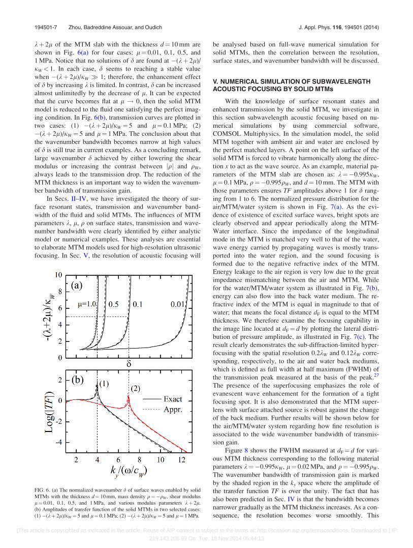
kþ 2l of the MTM slab with the thickness d¼ 10 mm are
shown in Fig. 6(a) for four cases: l¼ 0.01, 0.1, 0.5, and
1 MPa. Notice that no solutions of d are found at �(kþ 2l)/
jW< 1. In each case, d seems to reaching a stable value
when �(kþ 2l)/jW � 1; therefore, the enhancement effect
of d by increasing k is limited. In contrast, d can be increased
almost unlimitedly by the decrease of l. It can be expected
that the curve becomes flat at l ! 0, then the solid MTM
model is reduced to the fluid one satisfying the perfect imag-
ing condition. In Fig. 6(b), transmission curves are plotted in
two cases: (1) �(kþ 2l)/jW¼ 5 and l¼ 0.1 MPa; (2)
�(kþ 2l)/jW¼ 5 and l¼ 1 MPa. The conclusion about that
the wavenumber bandwidth becomes narrow at high values
of d is still true in current examples. As a concluding remark,
large wavenumber d achieved by either lowering the shear
modulus or increasing the contrast between jqj and qW,
always leads to the transmission drop. The reduction of the
MTM thickness is an important way to widen the wavenum-
ber bandwidth of transmission gain.
In Secs. II–IV, we have investigated the theory of sur-
face resonant states, transmission and wavenumber band-
width of the fluid and solid MTMs. The influences of MTM
parameters k, l, q on surface states, transmission and wave-
number bandwidth were clearly identified by either analytic
model or numerical examples. These analyses are essential
to elaborate MTM models used for high-resolution ultrasonic
focusing. In Sec. V, the resolution of acoustic focusing will
be analysed based on full-wave numerical simulation for
solid MTMs, then the correlation between the resolution,
surface states, and wavenumber bandwidth will be discussed.
V. NUMERICAL SIMULATION OF SUBWAVELENGTHACOUSTIC FOCUSING BY SOLID MTMs
With the knowledge of surface resonant states and
enhanced transmission by the solid MTM, we investigate in
this section subwavelength acoustic focusing based on nu-
merical simulations by using commercial software,
COMSOL Multiphysics. In the simulation model, the solid
MTM together with ambient air and water are enclosed by
the perfect matched layers. A point on the left surface of the
solid MTM is forced to vibrate harmonically along the direc-
tion x to act as the wave source. As an example, material pa-
rameters of the MTM slab are chosen as: k¼�0.995jW,
l¼ 0.1 MPa, q¼�0.995qW, and d¼ 10 mm. The MTM with
those parameters ensures TF amplitudes above 1 for d rang-
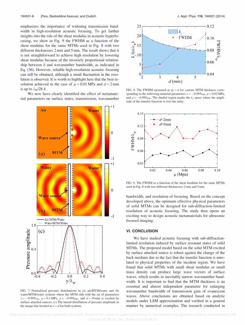
ing from 1 to 6. The normalized pressure distribution for the
air/MTM/water system is shown in Fig. 7(a). As the evi-
dence of existence of excited surface waves, bright spots are
clearly observed and appear periodically along the MTM-
Water interface. Since the impedance of the longitudinal
mode in the MTM is matched very well to that of the water,
wave energy carried by propagating waves is mostly trans-
ported into the water region, and the sound focusing is
formed due to the negative refractive index of the MTM.
Energy leakage to the air region is very low due to the great
impedance mismatching between the air and MTM. While
for the water/MTM/water system as illustrated in Fig. 7(b),
energy can also flow into the back water medium. The re-
fractive index of the MTM is equal in magnitude to that of
water; that means the focal distance dF is equal to the MTM
thickness. We therefore examine the focusing capability in
the image line located at dF¼ d by plotting the lateral distri-
bution of pressure amplitude, as illustrated in Fig. 7(c). The
result clearly demonstrates the sub-diffraction-limited hyper-
focusing with the spatial resolution 0.2kW and 0.12kW corre-
sponding, respectively, to the air and water back mediums,
which is defined as full width at half maximum (FWHM) of
the transmission peak measured at the basis of the peak.27
The presence of the superfocusing emphasizes the role of
evanescent wave enhancement for the formation of a tight
focusing spot. It is also demonstrated that the MTM super-
lens with surface attached source is robust against the change
of the back medium. Further results will be shown below for
the air/MTM/water system regarding how fine resolution is
associated to the wide wavenumber bandwidth of transmis-
sion gain.
Figure 8 shows the FWHM measured at dF¼ d for vari-
ous MTM thickness corresponding to the following material
parameters k¼�0.995jW, l¼ 0.02 MPa, and q¼�0.995qW.
The wavenumber bandwidth of transmission gain is marked
by the shaded region in the ky space where the amplitude of
the transfer function TF is over the unity. The fact that has
also been predicted in Sec. IV is that the bandwidth becomes
narrower gradually as the MTM thickness increases. As a con-
sequence, the resolution becomes worse smoothly. This
FIG. 6. (a) The normalized wavenumber d of surface waves enabled by solid
MTMs with the thickness d¼ 10 mm, mass density q¼�qW, shear modulus
l¼ 0.01, 0.1, 0.5, and 1 MPa, and various modulus parameters kþ 2l.
(b) Amplitudes of transfer function of the solid MTMs in two selected cases:
(1)�(kþ 2l)/jW¼ 5 and l¼ 0.1 MPa; (2)�(kþ 2l)/jW¼ 5 and l¼ 1 MPa.
194501-7 Zhou, Badreddine Assouar, and Oudich J. Appl. Phys. 116, 194501 (2014)
[This article is copyrighted as indicated in the article. Reuse of AIP content is subject to the terms at: http://scitation.aip.org/termsconditions. Downloaded to ] IP:
219.143.205.99 On: Tue, 18 Nov 2014 05:44:13
emphasizes the importance of widening transmission band-
width in high-resolution acoustic focusing. To get further
insights into the role of the shear modulus in acoustic hyperfo-
cusing, we show in Fig. 9 the FWHM as a function of the
shear modulus for the same MTMs used in Fig. 8 with two
different thicknesses 2 mm and 5 mm. The result shows that it
is not straightforward to achieve high resolution by lowering
shear modulus because of the inversely proportional relation-
ship between d and wavenumber bandwidth, as indicated in
Eq. (36). However, reliable high-resolution acoustic focusing
can still be obtained, although a small fluctuation in the reso-
lution is observed. It is worth to highlight here that the best re-
solution achieved in the case of l¼ 0.01 MPa and d¼ 2 mm
is up to kW/28.4.
We now have clearly identified the effect of metamate-
rial parameters on surface states, transmission, wavenumber
bandwidth, and resolution of focusing. Based on the concept
developed above, the optimum effective physical parameters
of solid MTMs can be designed for sub-diffraction-limited
resolution of acoustic focusing. The study then opens an
exciting way to design acoustic metamaterials for ultrasonic
focused imaging.
VI. CONCLUSION
We have studied acoustic focusing with sub-diffraction-
limited resolution induced by surface resonant states of solid
MTMs. The proposed model based on the solid MTM excited
by surface attached source is robust against the change of the
back medium due to the fact that the transfer function is unre-
lated to physical properties of the incident region. We have
found that solid MTMs with small shear modulus or small
mass density can produce large wave vectors of surface
waves, which results in inevitably narrow wavenumber band-
width. It is important to find that the MTM thickness is an
essential and almost independent parameter for enlarging
wavenumber bandwidth of transmission gain of evanescent
waves. Above conclusions are obtained based on analytic
models under LSM approximation and verified in a general
manner by numerical examples. The research conducted in
FIG. 8. The FWHM measured at dF¼ d for various MTM thickness corre-
sponding to the following material parameters k¼�0.995jW, l¼ 0.02 MPa,
and q¼�0.995qW. The shaded region marks the ky space where the ampli-
tude of the transfer function is over the unity.
FIG. 9. The FWHM as a function of the shear modulus for the same MTMs
used in Fig. 8 with two different thicknesses 2 mm and 5 mm.
FIG. 7. Normalized pressure distributions in (a) air/MTM/water and (b)
water/MTM/water systems where the MTM slab with the set of parameters
k¼�0.995jW, l¼ 0.1 MPa, q¼�0.995qW, and d¼ 10 mm is excited by
surface attached sources. (c) The lateral distribution of pressure amplitude in
the image line located at x¼ d for both systems.
194501-8 Zhou, Badreddine Assouar, and Oudich J. Appl. Phys. 116, 194501 (2014)
[This article is copyrighted as indicated in the article. Reuse of AIP content is subject to the terms at: http://scitation.aip.org/termsconditions. Downloaded to ] IP:
219.143.205.99 On: Tue, 18 Nov 2014 05:44:13
this work will be helpful for designing effective physical pa-
rameters of solid MTMs for high resolution acoustic focusing.
ACKNOWLEDGMENTS
M.B.A. and M.O. would like to thank “La R�egion
Lorraine” for its financial support. X.Z. acknowledges
supports from the National Natural Science Foundation of
China (Grant Nos. 11172038 and 11221202) and Program for
New Century Excellent Talents in University (Grant No.
NCET-11-0794).
1L. Fok, M. Ambati, and X. Zhang, MRS Bull. 33, 931–934 (2008).2M.-H. Lu, L. Feng, and Y.-F. Chen, Mater. Today 12(12), 34–42 (2009).3S. Zhang, L. Yin, and N. Fang, Phys. Rev. Lett. 102(19), 194301 (2009).4J. Li, L. Fok, X. Yin, G. Bartal, and X. Zhang, Nature Mater. 8(12),
931–934 (2009).5J. Zhu, J. Christensen, J. Jung, L. Martin-Moreno, X. Yin, L. Fok, X.
Zhang, and F. J. Garcia-Vidal, Nat. Phys. 7(1), 52–55 (2011).6X. Ao and C. T. Chan, Phys. Rev. E 77(2), 025601 (2008).7Y. Cheng, C. Zhou, Q. Wei, D. Wu, and X. Liu, Appl. Phys. Lett. 103(22),
224104 (2013).8H. Jia, M. Ke, R. Hao, Y. Ye, F. Liu, and Z. Liu, Appl. Phys. Lett. 97(17),
173507 (2010).9A. Liu, X. Zhou, G. Huang, and G. Hu, J. Acoust. Soc. Am. 132(4),
2800–2806 (2012).10X. Zhou and G. Hu, Appl. Phys. Lett. 98(26), 263510 (2011).
11J. Christensen and F. J. Garc�ıa de Abajo, Appl. Phys. Lett. 97(16), 164103
(2010).12D. Lu and Z. Liu, Nat. Commun. 3, 1205 (2012).13J. B. Pendry, Phys. Rev. Lett. 85(18), 3966–3969 (2000).14X. Zhang and Z. Liu, Nature Mater. 7(6), 435–441 (2008).15M. Ambati, N. Fang, C. Sun, and X. Zhang, Phys. Rev. B 75(19), 195447
(2007).16S. H. Lee, C. M. Park, Y. M. Seo, Z. G. Wang, and C. K. Kim, Phys. Rev.
Lett. 104(5), 054301 (2010).17C. Park, J. Park, S. Lee, Y. Seo, C. Kim, and S. Lee, Phys. Rev. Lett.
107(19), 194301 (2011).18W. Akl and A. Baz, J. Appl. Phys. 111(4), 044505 (2012).19J. Christensen and F. J. G. de Abajo, Phys. Rev. Lett. 108(12), 124301
(2012).20Z. Yang, J. Mei, M. Yang, N. Chan, and P. Sheng, Phys. Rev. Lett.
101(20), 204301 (2008).21Z. Liu, X. Zhang, Y. Mao, Y. Y. Zhu, Z. Yang, C. T. Chan, and P. Sheng,
Science 289(5485), 1734–1736 (2000).22K. Deng, Y. Ding, Z. He, H. Zhao, J. Shi, and Z. Liu, J. Appl. Phys.
105(12), 124909 (2009).23X. N. Liu, G. K. Hu, G. L. Huang, and C. T. Sun, Appl. Phys. Lett. 98(25),
251907 (2011).24Y. Lai, Y. Wu, P. Sheng, and Z. Q. Zhang, Nature Mater. 10(8), 620–624
(2011).25R. Zhu, X. N. Liu, G. L. Huang, H. H. Huang, and C. T. Sun, Phys. Rev. B
86(14), 144307 (2012).26R. Zhu, X. N. Liu, G. K. Hu, C. T. Sun, and G. L. Huang, J. Sound Vib.
333(10), 2759–2773 (2014).27A. Sukhovich, L. Jing, and J. H. Page, Phys. Rev. B 77(1), 014301
(2008).
194501-9 Zhou, Badreddine Assouar, and Oudich J. Appl. Phys. 116, 194501 (2014)
[This article is copyrighted as indicated in the article. Reuse of AIP content is subject to the terms at: http://scitation.aip.org/termsconditions. Downloaded to ] IP:
219.143.205.99 On: Tue, 18 Nov 2014 05:44:13