The influence of microphone vents on measurements of acoustic intensity and impedance
Upload
khangminh22Category
view
1download
0
(_AS_-C_-120Oa_) ACOUSTIC GRA2ING I:'LOtI g')5-10351 _,'_ZHEF,OAHCB US_.I1G OAVBGU]:bE PIIX_C_PLES_I_O,_£ng Co.e glchttae Sans.) 109 p Hl_$5.,_.5 CSCL 20D Unclas
G3/3q 0216_
NASA CR 120848BOEING D3-8884
tml
ml
ACOUSTICGRAZING FLOW IMPEDANCE
USING WAVEGUIDE PRINCIPLES
= BY_. D.L. ArmstrongII
DECEMBER 12. 1971 I_'_° NOVIg_4 :_:_
• PREPARED FOR
i NATIONAL AE_IONAUTICS AND SPACE ADMINISTRATION,,d
---! NASA-LEWiS i_ESEARCH CENTER_l CONI"RACT NAS 3-14321
H. BLOOMER° PROJECT MANAGER
00000001

"" [
L t n L L [
!Jl i i m i i i
NOTICE [Thi_ report was prepared as an =.count bf Government-sponsored work. Neither the United Statos, nor the National JrAeronauticsand Space Admihistratton (NASA), nor any person L
a
acting on behalf of NASA:mP
• , A.) Makes any warranty or representation,expressed Lor implied, with respectto the accuracy,complete-ness,or usefulnessof the information containedin rthis report, Or that the use Of any information, L..appaCatu_,method, or process disclosed in thisreport may not infringe privately_wned dghts; or Ir
LB.) Assumes any llabilide_with respectto the useof,
or for damages re_ulting from the use of, any rinformation, app_rdtus, method dr processdisclosedin thi_ report.
ak,
As usedabove, "persOnacting oh behalf of NASA" includesanyemployee or contractor of NASA, or employee of such
m.
contractor, to the extent that suchemployee or contractor ofNASA or employee of _uch contractor prepares,dlsser_inata_,. |ot provides accessto any information pursuant to ht_ employ- It.
ment ol" contract with NASA, or his employment with such
contractor. [- i1! i i
[-
• |
Retluests_orcopiesof this report shb(Jldbe referredto eNational Aeronduties and SpaceAdministration t_Sciedtific andTechnical Information Facitity
CollegePark, Md. 20740
.............. 1t3t3(3(313NN1_T_n_

i
NASA CR 120848
BOEING D3-8684 t;
)
TOPICAL REPORT
!
ACOUSTIC GRAZING FLOW.IMPEDANCE USINGWAVEGUlDE PRINCIPLES
by _D. L. Armstl"o_g
THE BOEING COMPANY3801 SOUTH OLIVE R
WICH ITA, KANSAS 67210
tJ
Prepared For . lI
NATIONAL AERONAUTICS AND SPACE ADMINISTRATIONi
December 12, 1971 "" I
t
• "CONTRACT NASA 3-14321 " _
NASA-LEWIS RESEARCH CENTERCLEVELAND, OHIO '
H. BLOOMER, PROJECT MANAGER
V/STOL AND NOISE DIVISION '.
00000001-TSA04
' I
i
!.
FOREWORD
The work describedherein was done by The Boeing Compar_y,': th'ichita 0ivision, under NASA cOntract NAS 3-14321 with Mr.
H. Bloonler, V/STOL and Noise bivision, NASA-Lewis': "- ResearchCenter, asProject Madager.
t
. ! .i
'!If
00000001-TSA05

,,
ABSTRACt'
A grazingflow apparatufihas been designedtO mea_brethe irhpeditriceof acOusticmaterials whenin_talleit ih environments that subje_ the material to glazing airflow. The designof the apparatusand the data analysis technique ts basedon the solution of th,_convected wave equation in aninfinite length waveguide.
i!
00000001-TSA06

TABLE OF CONTENTS
PAGE i
1.0 SUMMARY ......................... 1
2.0 INTRODUCTION ...................... 32.1 Backuround ......................... 32.2 Objective ..................... , ..... 32.3 Tectmical Al_prOach ........................ 4
3.0 MATH EI_,sATICA_.MODEL .................... 5
4.0 METHOD OF SOLUTION APPLICATION .............. 9
5.0 GRAZING FLOW IMPEDANCE APPARATUS ............ 13
6.0 BOUNDARY LAYER VELOCITY PROFILES ............ 17
).0 IMPEDANCE N!ODELS FOR PERFORATED SHEETAND POLYIMIDE ........................ 21
7.1 P_rforatedSheet ImpedanceModel ................._.2 Polyimtde Impt_tlanceModel ...................
8.0 DATA SUMMARY ....................... 25
g.0 RELATIVE ERROR OF (MPEDANCE MEASUREMENTS ......... 39
10.0 CONCLUSIONS ...................... . .... 43@
11 0 REFERENCES .- 45
APPENDIX .......................... 47
00000001-TSA07
LIST OF FIGURES i!
FIGURE TITLE PAGE
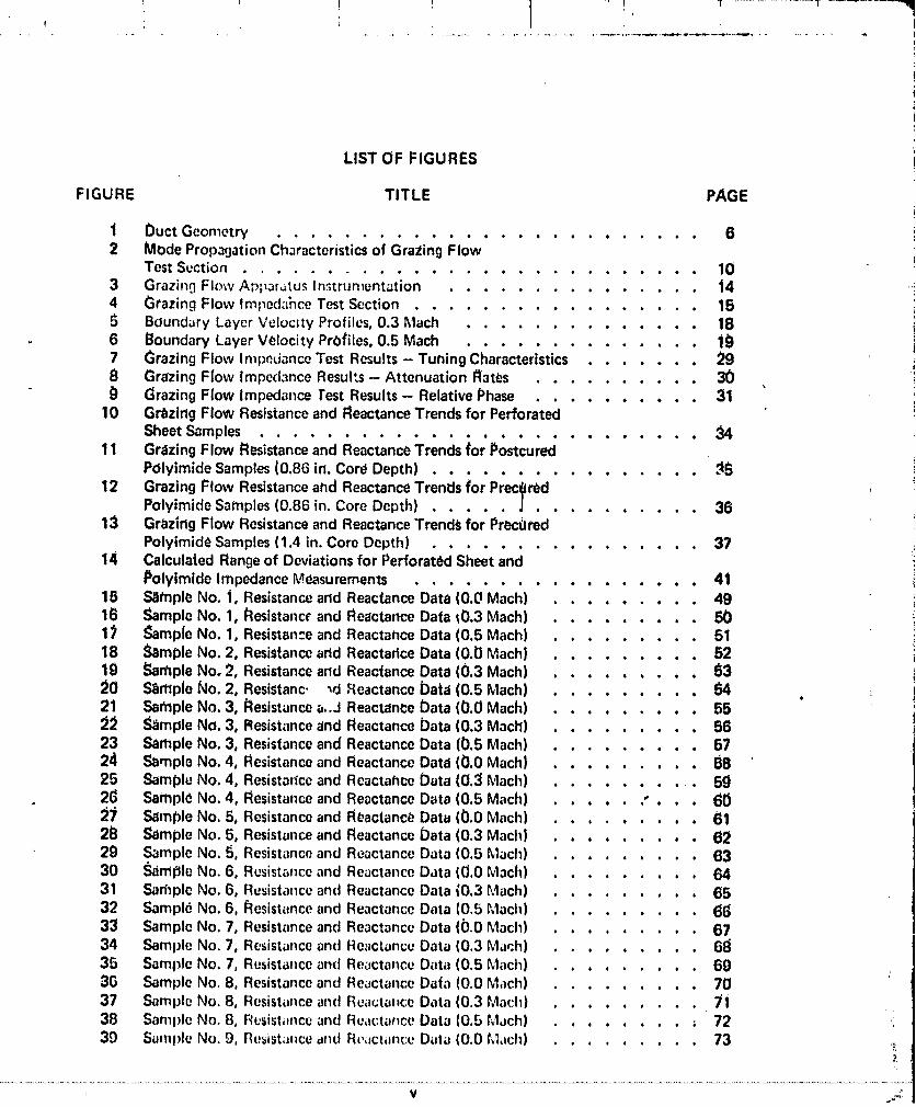
1 Duct Geometry ......................... 62 Mode Propa(jationChoracteristicsof Grating Flow
Test Suction ........................ 103 Grazin0 Flow Ap;_ar,_tu_Instrumentation ............... 144 Grazing Flow Impod:l_ceTest Section ................ 155 Bound;JryLayer Velocity Profiles,0.3 Mach .............. 186 Boundary Layer Velocity PrOfiles,0.5 Mach .............. lg7 Grazing Flow ImpedanceTest Results- Tuning Characteristics ....... 298 Grazing Flow Imped,lnceResul'_s- Attenuation Rates .......... 30_} Grazing Flow Impedance Test Results- RelativePhase .......... 31
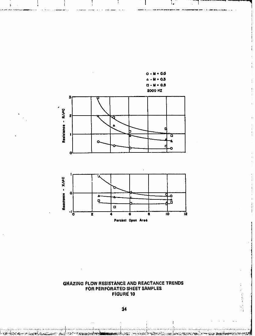
10 Gr_zlrlgFlow Resistanceand ReactanceTrends for PerforatedSheetSamples ................. 34
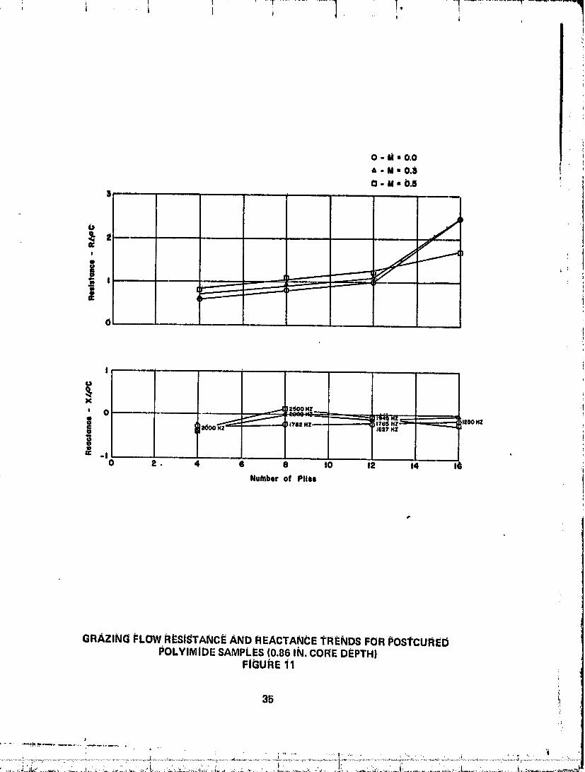
11 Grazing Flow Resistanceand Reactance;rrendsior Postcu;e;POlyimideSamples(0.86 in. Cort_Depth) ................ _S
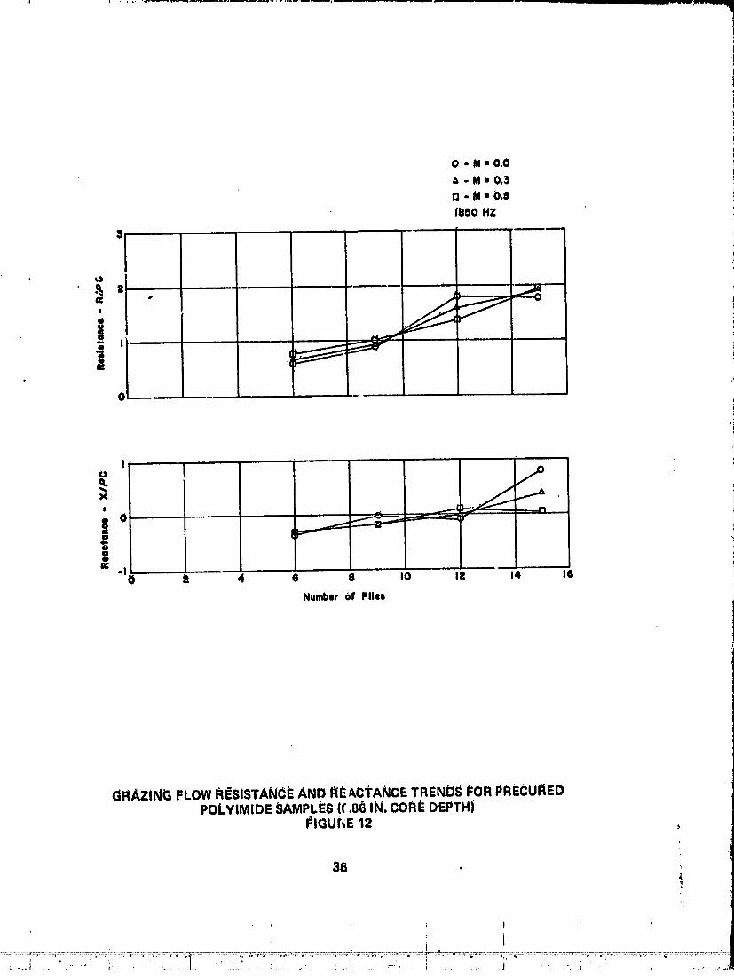
12 Grazing Flow Resistanceand ReactanceTrends for PrecOredPolyimide Satnples(0.86 in. Core Depth) ............... | • 36
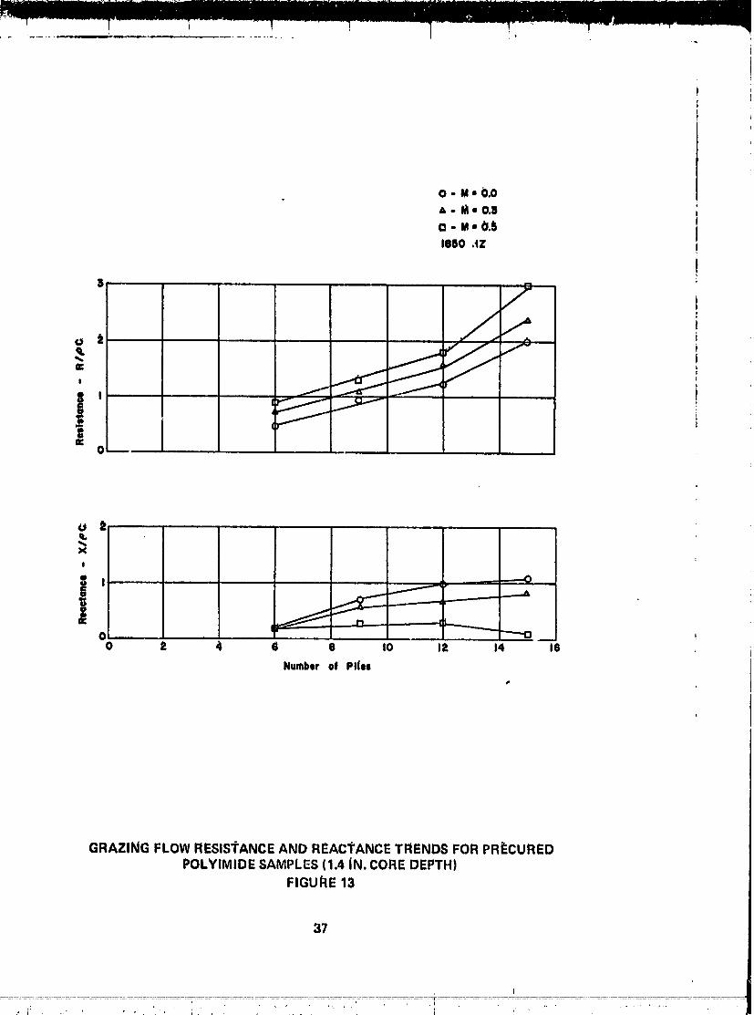
13 Grazing Flow Resistanceand ReactanceTrends for PrecgredPolyimide Samples(1.4 in. Core Depth) ................ 37
14 Calculated Rangeof Deviationsfor Perforated Sheet andPolyimide ImpedanceMeasurements ................. 41
15 Sampl(_No. 1, Resistanceand ReactanceData (0.0 Mach) ......... 4916 Sample No. 1, Resistanc_and ReactanceData t0.3 Mach) ........ 501_ _ample No. 1, Resistan:eand ReactahceData (0.5 Mach) ........ 5118 Sample No. 2, Resistancearid ReactariceData (0.0 Machl ........ 5219 Sample No, 2, Resistanceand ReactanceData (0.3 Mach) ........ 6320 S_mple No. 2, Resistanc. _dReactanceData (0.5 Mach) ........ 5421 Sample No. 3, Resistancea..J ReactanceData (0.0 Mach) ........ 552:2 _;_mpleNo. 3, Resistanceand ReactanceData (0.3 Mach) ........ 5623 Sample No. 3, Resistanceand ReactanceData (b.5 Mach) ........ 5724 Sample No. 4° Resistanceand ReactanceData (0.0 Mach) ....... 8825 Sample No. 4, Resistariccand ReactahceData (0.3 Mach) ........ 5g26 SamplONo. 4, Resistanceand ReactanceData (0.5 Mach) ..... " • • • 60;_7 Samtde No, 5, Resistanceand R(_actanceData (0.0 Mach) ...... 612B Sample No. 5, Resistanceand ReactanceData (0.3 Mach) ...... 6229 Sample No. 5, Resistanceand ReactanceData (0.5 Math) ..... 6330 Sample No. 6, Resistanceand Re_ctancoData (0.0 Math) . • . 6431 Sadlple No. 6, Resistanceand ReactanceData (0.3 Mach) . . . 6532 Sampl0 No. 6, _lesist_tnceand ReactanceData (0,5 Mach) .... 6633 Sample No. 7, Resistanceand ReactanceData (0.0 Mach) • • . 6734 Sample No. 7, Resistanceand Re_=ctuncuData (0.3 Much) • • . 6835 Saml_loNo. 7, Resistanceand ReoctanceD_lta (0.5 Mzlch) . . . 693(} Sample No. 8, Resistanceand ReoctanceDa(a (0.0 M_}ch) . . . 7037 Sample No. 8, Rt;sist_lnceand Re_lcta_ceData (0.3 Math) . . . 7!38 Sample No. 8, R_,,sist_mceand Re,_ctz_r_ceData (0.5 r,4och) . . = 72
39 Saml)le No. 9, H¢:_ist_,cednd R¢'_=ct_lnceData (0.0 k1,_ch) .... 73
00000001-TSA08

!LIST OF FIGuREs (CONT'D °1
FIGURE TITLE PAGEI
40 Sample No. 9, Resistanceand ReactanceDatzi(0.3 Mach) . ........ 74 t
41 Sample Nb. 9, P.eslstdnceand I_eactanceData (0._ Mach) . ........ 75 _ "'_4_ Sample Nb. 10, P.esistanceand I_eactanceD_lttt(0.0 MzCh) ......... 76 li i43 Sample No. 10, Rbsistanceat_dI_Oactan_eDatd (0.3 MaC:h) ......... ??
44 Sample No:lO, Resistar_ce_lrtdR_actanceData (0.5 Mb(_h) ......... 78 I I45 Sample No. 11, Reslstaf_ceand ReactanceData (0.0 Mach) ......... ?g46 _ample No. 11, Resistanceand ReactanceDat_ (0.3 Mach) ......... 8047 _ample NO.1i, R_taNce andReactance Data(0.5Mach) ......... 81 J48
Sample No. 12, Resistanceand ReactanceData (0.0 Math) ........ 8249 Sample _1o.12, Resistanceand Reactant:eData (0.3 Milch) ......... 8_150 Sample No. i2, Resistancearid ReactanceDat=i(0.$ Mach) ......... 84
(51 Sample No. 13, Resistanceand ReactanceData (0.0 Mach) ......... 8_ (_52 SarriplbNo. 13, Resi_tanceand ReactanceData (0.:3Mach) ......... 8653 Sample No. 13, _lesistanceand Reactanci_D=tta(0.5 Mar,h) ......... 87
!_4 Saml_leNo. 14, Resistanceand ReactanceData (0.0 Mach) ......... 88 I55 Sample No. 14, Resistanceand Reactance Data (0.3 M_lch) ......... 89_6 Sample No. 14, Resistanceand ReactanceData (0.5 Ma_:h| ......... go !5_ Sample No. 15, Resistanceand Reactancebata (0.0 Mach) ......... 9| =58 Sample No. 15, I_esistanceand Reactance Data (0.3 Mac:h) ..... .... _t2 _6_t Sample No. 15, Resistanceand ReactanceData (0.5 Mach) ......... 9360 Sampl_ No. i 6, Resistanceatld Rea_tanc_Data (0.0 Math) ......... g4I_1 Sampl_ No. 16, Resi_tan_ and ReactanceData (0.3 Mach) ......... 9_ _6:2 Sample No. 16, R_istance and ReactanceData (0.5 Ma_:h) ......... 9663 Sample No. 17, Resistanceand ReactanceData (0.0 Mach) ......... 97 ,¢64 Sample No. 11, ' _eactance Data (0.3 M_lch| 98Reststanceand (_65 Samp_.N.b. 17. Resistanceand ReactanceData (0.5 Mach) ......... 99
!¢
•, °
00000001-TSA09
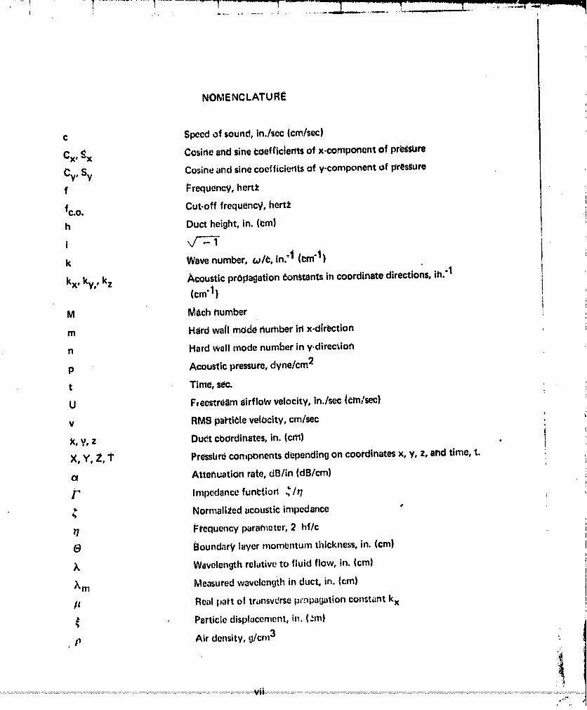
NOMENCLATURE
c Speedof sound, in./soc(cm/sec)
Cx, _:x Cosirteand sinei:oef¢iclent=of x-component of pr_lure
Cy, Sy Cosineat_dsinecoefficieritsof y-component of pressure
f Frequency, hert_
fc.o. Cut-off frequency, hertt
h Duct height, in. (l:m)
ik Wave number, _/¢, in.:1 (era"i)
kx, ky,, kz Acoustic pr6pagation donttants in coordinate directions, ih."1(cm'l)
M M_ch number
m Hard wail mode riumber irt x-direction
n Hard wall mode number in y.direction
p Acousticpressure,dyne/cm2
t Time, sac.
U Fteostre_tmairflow velocity, in./sec (_m/sec)
v RMS particle velocity, cm/sec
X, y, z Du_ cbordinates, in. (cm}
X, Y, Z, i" Presslurdcon_ponentsdbpendingon coordinatesx, y, z, and time, t.
Attef_uationrate, dB/in (dB/cm)
/" Impedancefunl:tion _/r/
_, Normaiizedacousticimpedance
17 Frequency parameter,2 hf/c
(_ Boundary laver mombntum thickness, in. (cm)
_, Wavelengthrelativeto fluid flow, in. (cm)
_m Measuredwavelengthin duct, in. (cm)
/_ Real part of tr_nsvUrsepr._pagationconstantkx
_ Particledisplacement,in. (:m)
, p Air density,g/cm3 _
vii :::!
O0000001-TSAIO

tNOMENCLATURE t
o Attenuadon p0rameter, inlag_naryp_rt of axial pro_agation [
¢ohstantkz
1" Phasevelocity I_ra_neter, real part of axial propagadon t
constantkz
R Pha_ePate,dog/in. (d0g/cm) t
X Imaginary part of trans_e_e propdgation¢or_tant kx .i
o_ . Angular frequency, 2/1" f, rad/s_c. 1
I .
• IIt
00000001-TSA11

1.0 SUMMARY
A gr_zlt_gflow apparatuswas dasi_jnedattd (abrica_edfor the I_ur_oseOf hieast/¢ingther_istivo and reactive acodstic impedance bf materials as inbtalJed in the i_resene_ofgrazing ell'flow. 1"hedesigno_ the apparatusand the analysi_o_ the data were basedonthe theory of soundpropagation in a reCtahgulalwaveguide.The resultsof the testingindicate that the change in resistiveand reactive impedance, as a functiOtl of grazin1_flow, is greater for the perforated theet materials than that fbr the polyim_dematerials_ested. In a u¢.ner,dsense, the model predictions i:ompar6 favOrttlJlytO the data_onsideringthat f,,cino sheet blockageduoto the adhc;ive fillet betWeef_the core and thefaciflg sheet and that the bouddary layer effects on the impedance measurementshavenot been incorporated in the model predictionsor the data anblysls.
_asddon the tesult_of te_ting to daffi, there are_everalareasthat warrant improvementwhlch would expand the capability of the grazing flbw fabiiity. Recommende¢limprovementsare listedbelow:
• Increasingthb adbusttctransmi_ion efficiency of the waveguide .:
• Increasingthe frequ_ricy range
• Changingthe bourtoarylayer profile
• Usirtg two simultaneously tratwersirtg miCrophone_and cross-correlatt_n itechhiquesto Obtaindata
• Int:rea_;;ngthe soundpressurelevel input
f
t
fi
• 1iii
t
• i
i
00000001-TSA12

2.0 INTRODUCTION
2.1 BackgroUnd
Two different methods have previously Leen used to mea_ire grazing flow impeda,_.References1, 2, 3, and4 employed the bye pressuremethod and Reference5 employeda standino wave tub : mounted in the side of a rr:ctangularflow duct.
The two pressuremethod of determining the comple.ximpedance is basedori measuringthe _ouhclpressuredifference and phasedifferel_ce acro_sthe resonatoraperture. Binek(in Reference4) statesthat under grazing flow conditions no phasemeasiJrementsweretaken indicating irtstrurttentation problems. As a result, he assumed the reactiveimpedanceto be a linear functioh of frequency, which is zero at the reSOnantfrequertcy,and computed the correspondingphase anglesat the freqdenciesof intet_t. However,the other investigators(ReferenCes1, 2, and 31 make no mention of su_..h(abaseproblemsbut they do make extensive u_ of the re_nant frequettcy ptopertie_ of a Helmholtzr_sonatorin determining resistance,as well as reactance.The resonantfre_luencycan !_determined by measuringminimum pressure_e)_terlorot maximufn pressuresinterior tothe resonator without making phase measurements.The phase measuremedt, thus,appearstO be an inherent weaknessin the two pressuremethod of detet'm_ninggrazingflow impedant_}s.
Feder (Reference 5) measured grazing flow impedance with a standing wave tubemounted in a flow duct wall by subtracting out the measured radiation impedancewithout the _ample installed. However, the radiation impedanceof a petfotated _heet
hol_to-hole interaction) is-S-ptimesthe radiation impedanceof one_mpie (a_summgno
hole where S is the cross sectional area of one hole and OA is the open area of thesample. "this can differ significantly ft'om the radiation impedanceo_ the open endedstat_dingwave tube. Also, the effect of grazingflow on the radiation impedanceneedstobe Incorporated. Therefore, an inherent limitation in thd measdringtechniqu_ bec0rhesapparent.
"r'heWaVeguidi_mbthdd of measurirlg grazing ttlow impedance, as developed in this_locurhent,also has several limitations. HoWeveP,thd majot"limitation ap_eal_ to be inthe magnitude of the standing wave inside the test section at higher Mach numbers, asindicated Ih the data scatter. This can be overcome by a redesign of the acousticcomponentsof theapparatus.
2.2 Objective
The objective of this researcheffort was to develop a grazing flow apparatusin whichboth the resistiveand reactiveacoustic impedancesbf a material can be deterhninedinthe _resencoof a grazing airflow. From this information, more realisticmathematicalimpedancemodelscan be developed.
00000001-TSA13
2.3 TechrticalApproach
The designof ;he apparatusand the analysisof the data are basedor, ',.herequire., 0nt forthe' propagation Of the fundmllenzolmode in the Zestsection,one wall of which can belined with an acoustic p3rlel.This designrequirementautomatically limits the frequencyrange for the impedance measurements to those frequencies below the first _utofffrequency of the wave3uide.At higher frequencies,the higher modesadverselyaffect themeasuromerttof the attenuation rate ahd phaserate in the waveguide.
00000001 -TSAI 4
tII
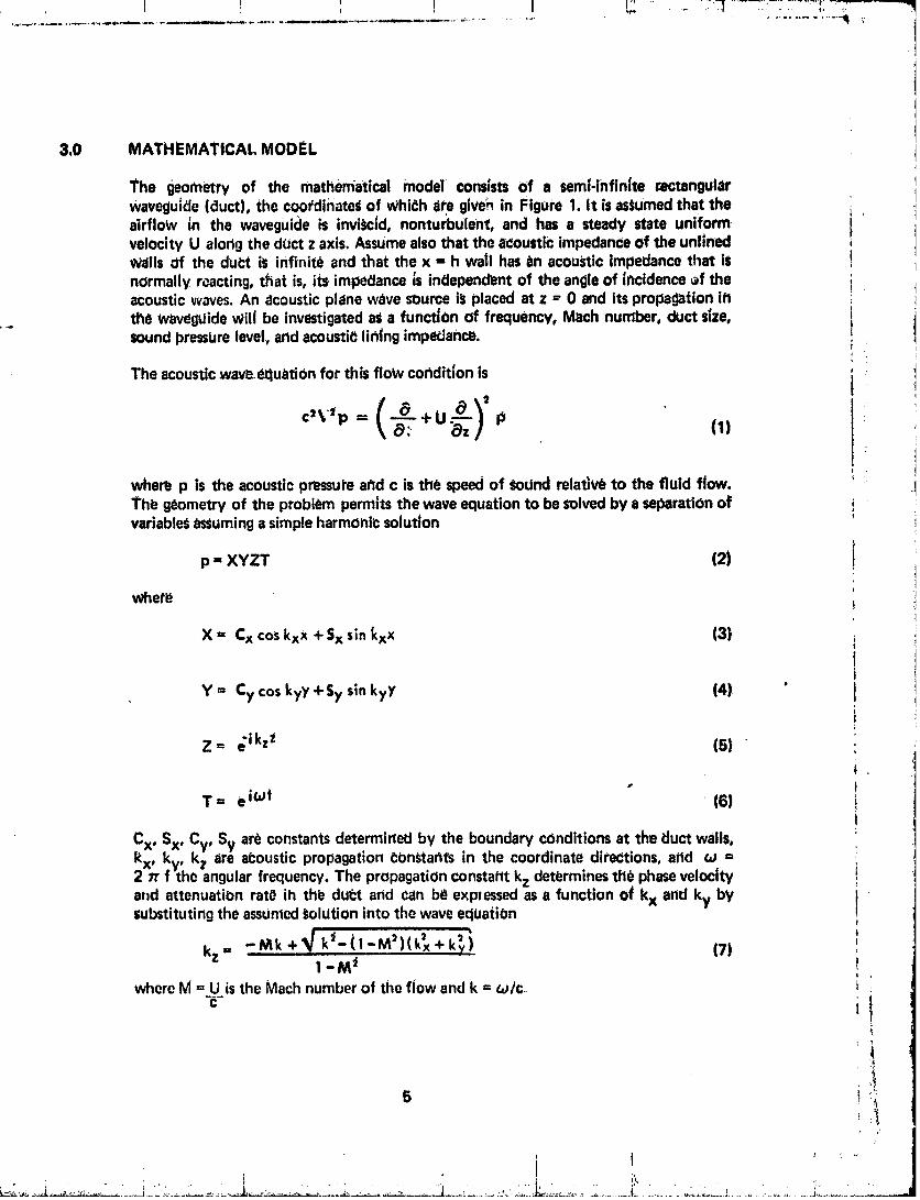
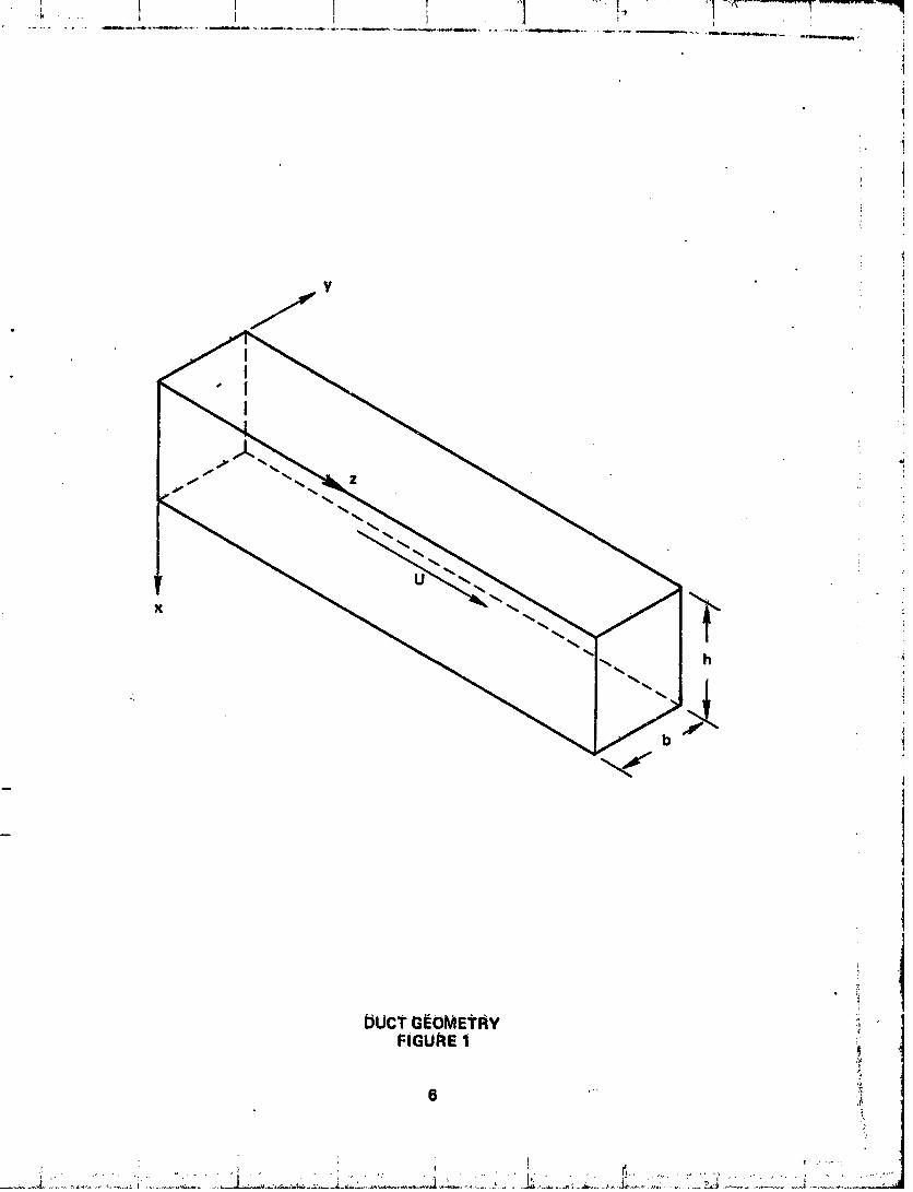
i3.0 MATHEMATICAL MODEL t
The geometry of the mathematical model cons|sts Of a sem|-infln_te rectangular tIwavegulde (duct), the coordinatedof WhiChare give_ in Figure 1. It is assumedthat the i ]
airflow in the waveguicleis invitcld, nonturbulent, and has a steady state uniform t ]velocity U alorlg the duct z axis. Assumealsothat the a_oustic impedanceOf the unlinedwails of the du_:t is infinite and that the x = h wa_lhas in acoustic impedancethat is !
normally rcacting, that is, its impedance ;s independent of the angleof incidenceef the iacousticwaves.An acousticplane wzlvesource i!splaced at z ="0 and itspropagation itt i
the waveggidewill be investigateda_ a functJ0n of frequency, Mach number, duct size, isoundpresstJrelevel,and acousti_lih|ng impedance.
I
The acoustic wave,e_luationfor this flow cor_dit_onis tt
c ,tp = +U (1)
* t
whe_ p is the acousticpressureaf_dc is the speedof _)dnd reladv_ to the fluid flow. iThe g_ometry of the problem permits the wave equation to be solvedby a separationof ivariable_assuminga simpleharmOhi¢solution :
p = XYZT (2) i
i
whet_
X = Cx coskxx + Sx sin _xx (3)
lt
Y = Cy cos kyy +Sy sin kyy (4) " I
Z= e ikzt (5) •
" IT= e iOt (6)
t
Cx, Sx, Cv, Sy ar_ constantsdetermirt_ by the boundary conditions at the duct walls, ikx, kv, kz are at:ousticpropagation _bn_tahts in the coordinate directions, arid _ =2 :rrf'the angular frequency. The propagationconstaPttkz dett_rminestile phasevelocity !
a_d attenuation rat_ ih thl_ du_t and can be expressedas a function O_kx and ky by isubstitutingthe assumed_olgtion into the wave eqUatiOn i
' t
kz.. -Mk +_ k'_-tl-M'}(k_x*k_i (7) ',1 -M _
whoreM = U isthe Mach numberof the flow and k = 6_/c i
• ,}
5
_ ' i?,
00000001-TSB01
%U
z,'.
_UcT G_OMEtRY i_
FIGURE 1
00000001-TSB02
The boundaryc_ndltion UsedtO determinekx _nd kv fSthat of the continuity ofpartlcle displacementat the duct walls. Thus, at the 'wall let (1 be the i_articledisplacementin the fluid flow normalto thewa!_.Theequationof modenil givenby:
-P + U (, = glad p 18)
where p isthedehsi_6f the fluid.
The hardwall boundaryconditionat Y = O,L1andx = 0 isequivalentto the requimmettt I• tha_the gradientof the pressurevanish•Thus,Sx andSy ai'ez_roand ky =1_,_.In the
I_resentappiicatioh,_ frequencyrangeusableis _ch that the tl = 1 modewill be inCutoff.Therefore,theeXpr_sionfor kz beComeS
--Mk,V k*xkz = ..... 1 -'M 2 " (g)
If the x = hwall is finedwith anacousticimpedance_ .normalizedby the characteristicaCOUstictmpedal_ceof the fluid Pc, thenthe)relationshipbetweenpres=Jreandparticlevelocityattt_elinedwall ;s
Pc_"= --£-_2 (I0)
where (2 is the particle displacement in the lining material, ASsumingsimpleharmonicmotion_
pc¢ .- P--
orP
i_Pc_ (11) ,
]The boundarv condition is the _quival_nceof _I and (2 at the soft wall. Theequationof motion nowbecbmCs
0),o o,o-P +U_-; i_Pc¢ - exor
-P(iw-iuk=)2 P = _i_Pc¢ _x
or
Ox (12) :
Usingtheassumedsolution,thisbecomes _'i
7
00000001-TSB03

,1
!
"_" -M = kx tan(hkx) (1_)
J
qSince kz is a COmplexquantity, it cah be represe_ntedas t
kz ,, k (7"-1o) 1141t
jThe transversepropagationeonstaht kx is a Cor_ple_(tua_ltltyand is representedby
I" _r
kx= __(p p °�4�¼�ll0)i
!
This repre_1_t_tlon is u_d so that t_ final results All be com_tible with Cr_ner_s( Reference61 at M ==O. Direct sabstitutlon and rearrangementyields !
• i
" _" =11 -M('r-io')) 2 ctnh (-itr(p+ix)) 'p+ ix 1171 ._
'i. where T/= 21_fis the frequt_ncyparatheter, i
¢ !
The quantities P. and X _re computed from the measurbdpropagationdonstant kz by_it_g.a N_vton-Rabh_n iteration t_hnique on Equation g after the real ( 7" ) andimaginary ((7) part_ have been seibarated.Thus, all the parameters necessarytodetermine _" in Equadon 17 II_ve been established.
0000000]-TSB04

4.0 METHOD OF SOLUTION APPLICATION
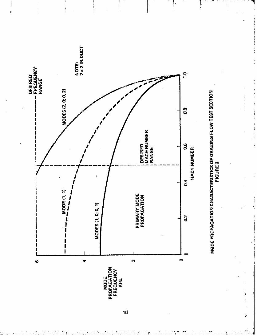
The gpper limit bf the usabt_ frequency range is det_rnlined by the Iow_st cutoff ifreq_Jencyof the waveOuide.This _:Utoff frequehCy dependson the Mach number and Iduct size accordingto Equdttbn ? at the frequency at whidh the radical vanishes.For a
!
squareduct with hardwails k_ = m_ , ky = '-1h and the cuto{f frequency is" t if=.o--
1
• for the 2 inch duct height of the test _ection. Figure 2 showsthe cutoff frequency forthe first five modes. The usable frequency range is determined by the (1,01 or (0,1}mode curve,
!Tht3Imp0clanceof the waveguidewall, as sensedby the wave travelingdown the duet, is igivenby Equation 17. The quantities measured in the duct are the real and imaginaryparts of the axial propagationconstant kz. From EquatiOn (5), the component of thepreSSurevariation down the waveguideis
Z= _ikzz
or
Z= _;k(_'-iO)z (19)
The phaseof the pressurein the d_ct repeatsevery 2_" r_diansfor Onewav_length in
th_ duct _ _i. Thus2_r
kT"or
-r - _ (20);_n_
Thi_attenuation in the duct per unit length ise"k° or "._termso'_dB/in.
dB/ln. = 8.68 ko (21}
Theref6re, by measurihgthe wavelength and the attenuation rate Iri the du(_t,EqUationS20 tnd 21 determine _ill the required parameters since /J and X ih Equation 17 aredetermined bV d and _" from Ec_uation9. The explicit expressions_fe asfollows:
1.-r _ + - + 4,,,,,,1-M _ _/2(1, M_)"
:I,_
g "i
I i '
00000001-TSB05
00000001-TSB06
II_-M"_' "\rlJ'_"_.J ) "1"4('_) :eI_TJ)-_, _ '
The_e equations can be _olved for_J_-and-_and the results used in Equation 17 to .................. .:;i'_,....¢ompgte the wall impedat_ce.
• The impedance data is pl_tted aS a function of the ditcrete frequency Sodrtdpressure !level (SPL) at the soft wall, ThLs SOL is computed froth the measured SPL on the ; ._.
. oppotite hard w_ll at the axial midpoint of the half wavelengthsection of data analyzed,
The, RMS soundpre_sur_at any location _crossthe du_ is givenas: i_
Px = Po (c°s2 (_rpx/h} + stnh = (_xx/h))V_ 1241: I
from which the RMSSPL at x = 2 inch iscomputed.
If the corresi_ondingRMS particie Vt_lOcltlesare desired,they can be computedfrom thefollowing expre_ion:
v = 12s)I¢lp ' "
• '°" i
t
O000000]-TSB07
i
5.0 (;RAZING FLOW IMPEDANCE APPARATUS
1"hegrazi,lg flow impedance al_paratuscS_sJstsbf =inair plenum, a soundsource, test !section,and aeroctynai'nicdiffuserwith an ar_echoictermination asShownin Figure 3. t
The air plenum ¢Ori_istsOf a 364nigh diameter cylinder lined with acousticJnsulati0nto i iminimi_e ai'ffiow nbise, an electr0pneumatic sound generatorand exponential horn thatprovides a uniTormdiscretefrequency sound wave i_to the testsection, i
A detai=ledview of the testsoctibnisshown in Figure4 andcotlsistsof a 2 x 2 _nchcrosSt section, the tOp wall Of which accbmmodatesa 1B inch test pahel.Two microphonc_are
mounted bpposite the test p_nel, one of which c_n traversethe lengthof the test section.The stationary microphone Ibcated opposite the leading edge of the te_t panel is thereference microphone. The traversingmtcrophohe is initially aligried with the referenceanctduring its traverse, in one-eighthtnc_hin_:rements,measuresthe relativL,amplitude iand phaseas a function of duct location. This information is recordedon a _X- y - Y"plotter for on-lineanalysi_and_1_opunchedoi_card_for digital _ompUterprocessing_ i
The exponential horn attar:healtO the downstream end of the test section servesasanaerodynamicdiffuser and acoustictransformer. The flare cutoff frequency bf the horn is100 HZ and, therefore, ha_ acceptabletransmiSSiOnproperties in the 1000 - 3000 Htfre¢i_Jtmcyrange that the impedancemeasurementsare made. However, an aerodynamicanalysisindicated that the flow will separatebetween 2 and 6 inche_from the throat Ofthe horn for a .2 to .5 Mach number range, thds, causingflow Sepi_rationno_seandr_brnatch in acoustic impedance resulting in reflected waves.The significanceof theserefitted waves dependsupon both the Mach number arid line#attenuation efficiency.Their effect oh the measureddata isquantitatively i:onSid_rL_clin SectiOn8.0
A portable an_:hoic chamber servesa_ an acouSti_termination for the apparatus andprovidesan effective nonreflectivetermination in the test frequency J'ac_ge.
:t
00000001-TSB08

i4
! i '
O0000001-T,SB09

REI_P_DUCiBILITY OF
O0000001-TSBIO

6.0 BOUNDARY LAYER VELOCITY PROFILES
Tyl_icaf boundary layer velocit? Drofl|¢s_re given in Figures 5+and 8 fop Mach numbersof ,3 and .5 for two dUCt locations; at tile leading etlge of the panel and at 14 in.downstroom. The momentIJm thickness 8 is indtl:ated. These velol:ity pr(_filesareindi(:ati_eOf all padolstested, both pePfOratedsheetand i_lyimide.
+
,t
PR_C_DN6PAGEBLA_ NOTF_ t7 i
,, ,+ _ + ! I+
O0000001-TSB11


r,: ut0
- II I
-_ _
i °_ _. _
......... _._ lli
-_-_ . _
\__
\aJ ....0
>I1
i _ I ", .... . ; _'"
O0000001-TSBI3

7.0 IMPEDANCE MODELS FOR PERFORATED SHEET AND POLYIMIDE
7.1 PerforatedSheet ImpedanceModel
"the perforated sht:et impedahce model was developed by combihiMg theoretlealexpressionsfor orifice impedance with measuredflow resistanceand stahdingwave tubeimpedanc_ data. The effect of grazing flow On the impedance was derived frommeasurementsof the DC flow resistanceof the material subjectedto the grazingflow bya method similar to that teported in Reference5. The follow;ng equationsrepresentthl_normalized resistance (R/Pc) and rea;tande (X" Pc} for the pel'forated sheet acousticpanel.
R_ = RVDC + ZJ + tr VE exp(_;N)Pc 2_' c
OA _TT7519" + .85d( 1 -.7 _ - .000012 Vt
where _ = Speedof sound(cm/sec)
d = I_erforatehole diameter (in)
f = Frequency (Hz)
k = 2/rf/c (_tn"1)
L = Panelcore depth (cm) *
M = Mach number
OA = Perforate openarea
PS = Static pressure(PSI)
t = Thicknessof perforated sheet (in)
1"T = Total air temperature (°k)
V = RMS total particle velocity (cm/s_c)
VSpL = RMS specti'umpalticle velocity (cm/sec)
VGF = RMS grazingflow particle velocity (cm/sec)
= Boundary layer momentum thickncss (in)
i i
O0000001-TSB14

.077t (TT/519 )2
a_ RVDC = PS OA T34.--_ _ + .418
zJ = .ooc03a(TT/ 19.75It* 1- OAt
"_4.7\519 -/
E = L0251 OA)2 1 exp(-.5072t/d)
SN = -1.8 (2.54 df ,OA)/V) 2
" The RMS total particle velocity I_ obto|ned by
_2 V2 "V = ¢ SP-L+ GF
= .25.(XKK) c_ 2
Where VGF R2OC , /___)2 + "-_XKK E M2'
005 ifE) = 0and XKK _= +.11 d/O ifO_ 0
7.2 Polyimide ImpedanceModel
The polvimide impedancemodel wa¢developedempiricafly ttromDC flow resistanceandstanding ,Nave impedance tube data. Ttle grazingflow contribution was determined asthat for the perforated sheet model. Tile following equations representthe normalttedresistance(R/Pc} and reactance(X/Pc) for the polyimide acousticpanel.
R = (RVDC + .305 AN 2 f + 2.86 P N2V}/P¢
X._ = (.549PNl'Sf--(5.12} lO'5pN3fV}/Pc-cot(kL)Pc
TS1.5Where A = (1.115) 10.5 TS'--_-21--_
RVOC = 4640 AN 1.333
N = Kumber of plie_
Ts = Static teml_erature(°R._
22 :'_!
; i I _t
'j .... • . .. ' .... I,'. _-' . .. ..... _. •. _ . .. .
00000001-TSC01

TheRMStotal particlevelocityisobtainedby
v = _/_-=+v_ "SPL F
With VGE = .05 cM2 r " I I • ,m
.vDc+"-jf.v_._.Dc?+.7,N2 M2PC _k Pc) /
23
00000001-TSC02

I _ ] T 7
I1
8.0 DATASUMMARY !d
Typical grazing flow impedancedata for 2.7% open area (OA} perforated sheet w_ll be !discussed.FigUre 7 show_the liner tdnihg Charadt_iristi_sas a function _f Mach humber _,for a constant 140 dB SPL input. As Math ntJmber increates, the frequency of peakattenuatiori increasesa_d-the attenuation deCreasesirtdicadnga dedreastngreactive at_dincreasingresistiveiml_edance.Figure 8 showsthe attenuation rates as a function of ductIo_:atJon for the peak ftequency of attenuation. FOr a given Mach number, theattenuation rate can be determined for a certaindu(:t location or it can be determined
Overa i:ertain duct section. Tl_e data points are least _uare fitted by a ='ttaight llnewhoseslope determinesthe atteniJationrate. This _.-t.en_Jationrate isascribedto the SPLat the section midpoint. The im_iginarypart of the axial propagationconstant is definedby the attenuation rate acCording to Equation 21. Figure g _hows the data fordetertnining the wavelengthin the duct as a fur_etionof Mach number. A relative phaseChangeof 180° indicatesa half wavelengthchange.For a given Math number, the pha_.rate can be determinedfor a Certainduct Io¢,ation,or it can bedetermined over a certail_duct t_ction such a_a 180° phasechangese0tion(half wavelength). The data pointsare
leastSquarefitted by a straight line, which, when extended over 180°, determinesthe ihalf wavelengthin the duc* The ratio of the waVelengtllrelativeto the fluid flow to the _,_measured:,avelength in the duct is the realpart of the axial propagationconstant.
i
This iS a general representationof raw data asob_ined from the grazingflow apparatus iand iSchara_:teristicsof all samplestested.ASexplained in _ection 4.0, the data for eachsample correspondir_gto F_gure_8 and 9 are punched on cardsfoi"data processing,Thisraw data will not be presenteddue to its bulk. The pl-ocessedraw data is presetltedin theAppendix ih the form of test panel installed impedance, resistiveand reactive. Table Ilists the physiC! properties of the panels tested. Table II give_ the flow resistanceCharacteristicSof the _amplef_cing sheetsin tcrmsof zero particle VelOciW|ntefeept aridslope.
t
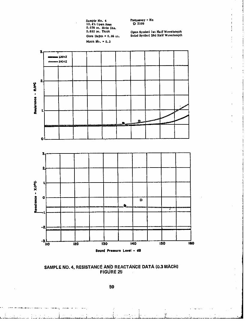
A summ_ty of the data in the Appendix i_ givenin Figures 10 through 13 for O, .3, arid.5 Mach numbers. The resistive 3nd reactive impedancesare plotted as a _nction of !!either percent open area (Figure 10) or number of plie_ (Figures 11, 12, and 13). A =comparison of Figures 10 through 13 indicate that the grazing flow contrZbution toperforated sheet is greaterthan that for polyimide. This data representsthe grazingflowcontribution to the impedanceat low input SPL particle velocities where the gi'azlng
flow particle velocity is dominant. The RM_;particle velocity due to gr_izincjflow cannot ibe determined from the data since sufficiently high input SPL's could _ot be producedtO _hducea particle velocity that dominates that produced by the grazingflow. If this !could be done, a transition would appear in the data from c_nstant r_Istant_e to a ird_i_tancedependent on the input SPL induced particle velocity, and this transitionwould define the grazingflow (oarticlevelocity, t
The summary chart for the perforated sheet panels is _jiVen in I:igure 10. Thecharacteristic increase in rL_istanceand decrease in reactancewith increasing MachnurflLleri_ indicated for all the sathplestested.
Three different set_ o_ polyimide panels were tested. The first Set (Saml_l(JNos. 6 _through 9} were fabricated from layersof glassfiber _:loth impregnated with polyimideresin. The layers were oriented at 0°, 22.5 °, 45°, 67.5 °, etc. Thes_ panels were :.
_w
i ,,
00000001-TSC03

post-cured, that is, th0v were heat treated it1air for artextra period of time at a highertemperature than the standard Drec_uredp_nels.
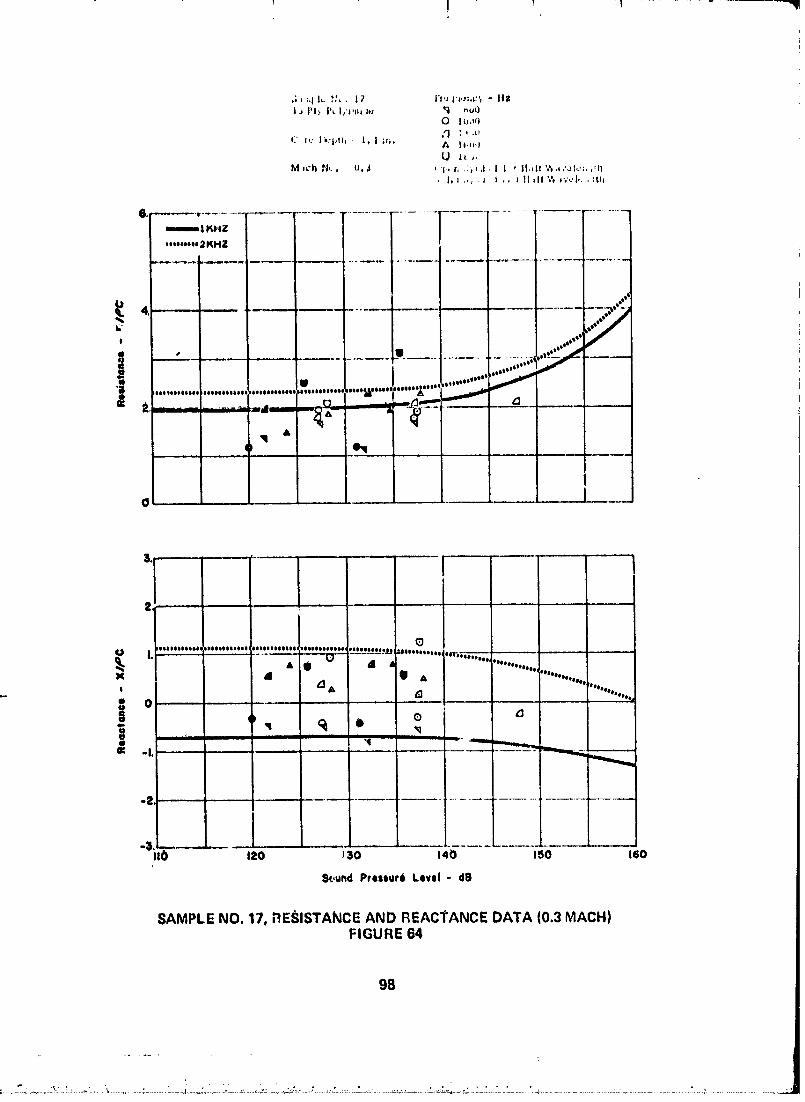
The _ecortdset (Sample Nee. 10, 12, 14, and 16) and the third set (Sample Nee. 11, 13,15, and 17) rliff_r Jn _onst_uction only l_l their rare depths, 0.86 in. and 1.4 in.,respectively.These pan,is ar_ of the standard pre_ur0d type with a weave orientation of0°, li_° right, 0 ° and 150 left, etc.
The summary (:harts fo/" the pc_lylmld0 panelsare given in Figures 11, 12, and 13,respbctively, for the three setsof part(._lsdefined above. The unusualbehaviorof the 1Bply panel, aS shown in F_gufe 11, Was possibly due to air leakagecaused by parcelwarpage that was not removed wtten installed irt the grazing flow apparatus. HoWeVer,the 4, 8, and 1_ ply panelsexlllbit resistanc6values that are lineal as a function (_fnumber of piles. The reactancesare strongerfunctions of ftequ(_ncythan the resistancesand, hence, _0w a greater variability since the reactances are plotted for differentfrequencies.
Figures 12 and 13 give the summ_ry chal-tsfor the pr.ecuredpolyimide panels with cote• depths of 0.86 in. and 1.4 in., respectively. By cofnparlng th_ two set_of curves,it will
be seen that the resistive characteristics are again _]enerallylinea_as to the number ofplies. HOwever, the slopes of the resistancecurves are different for the preGuredandpost-curedpanels.
It should be mentioned that the blockagedueto the adhesivefillet betweenthe core andfacir_ _heet affect_ the imlbedanceproperties of the polyimide panels.This blockageisvery Likely to vary fl'om panel to pan_l, _sulttng in a certain amount of val'iability ofmeasured impedance attd, thus, a_fec_tingthe general linear trends of the data as afunction of the number of plies.
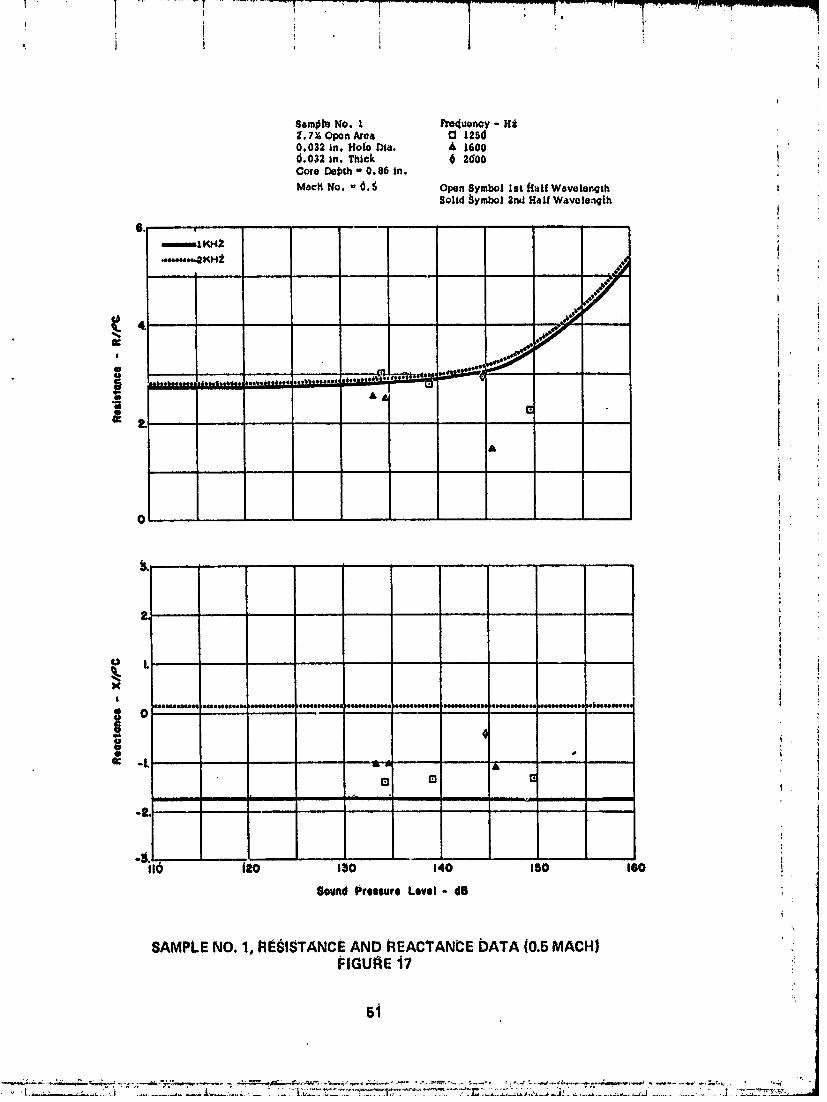
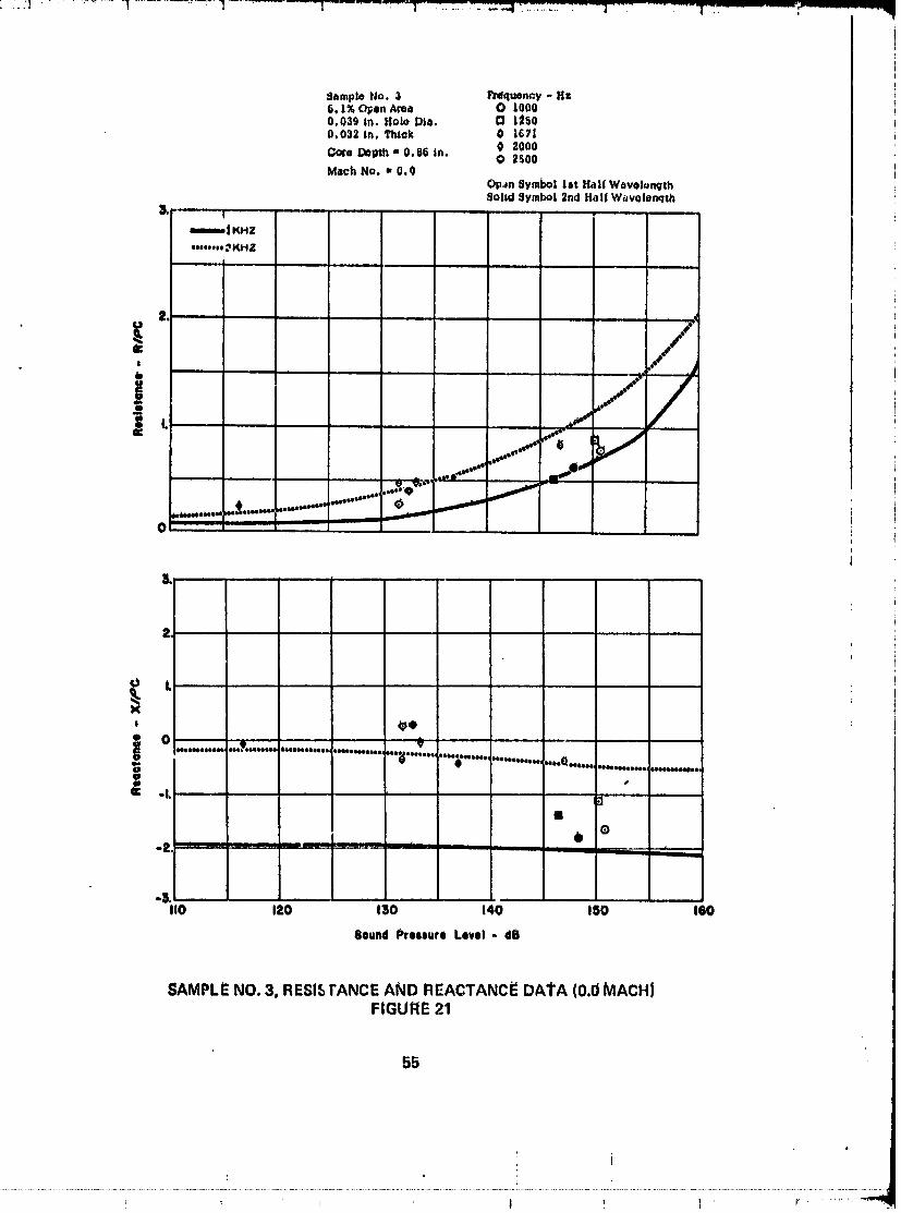
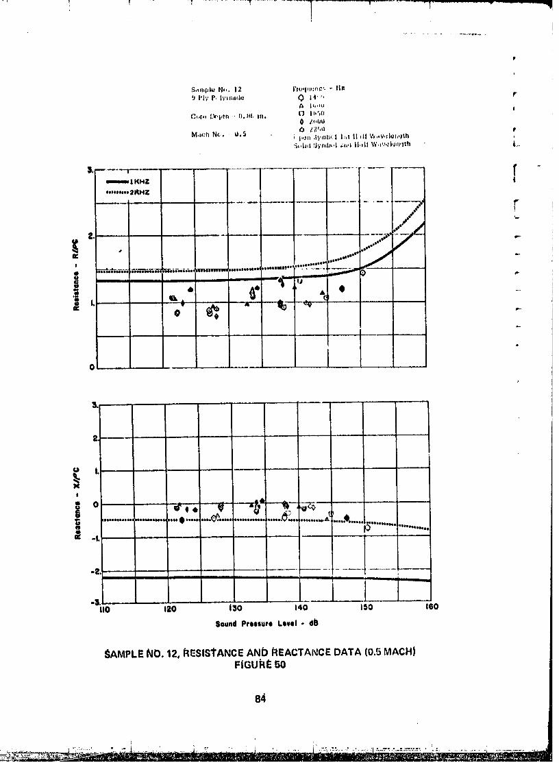
In the Data Appendix the first and sec_ondhalf wavelengthduct sectiondata _treplotted_s open and solid symbols. At zero Mach number, the two half wavelength sectionsexhibit data that have the same trends as a function Of SPL. At the higher Mach :tnumbers, the second section raststancedata generally indidat(_the higher value. Thiscould be inflictive of the depenLtenceof the panel impedatce on the boundary layerprofile that varies with duct length. At thi_ time, partel impedance correlation w_thboundary layer propertiesis not pos_lbla.
The impedance model predictions are plotted a_solid linesfor 1 KHz and dotted lin_sfor 2 KHz. I_or exa_nple,_ample 1 at zero MaC:hnumber indicatesthat the predictedresistive impedanc_ valuesare lower than the measuredvalues at low SPL's bdt _howbetter agreementabove 130 dB's. The abscissarbpresentsthe SPLof the sirlusoidalsignalat the panel _urf_c_eand not the total RMS SPL of the entire spectrum.Thus, at lowinput sinUsoidal levels, the background noise spectrum inducesan RMS particl6 velocitythat cortttols the reSiStivetl_pedahce.The reactiveimpedanceappearsto be lessaffectedby the background noise. This background noise could have been included in theimpedance computatiorts if it had been knoWh as a function of panel location. Uponc_thpating ttte other predictions arid data, it becomes apparent that generallythe zeroMach do:nparlsonsa_tebetter than tho_eat .3 or .5 Mach number. This is understandable
28
I I
O000000"l -TSC04

i
sincethe data includesthe boundarylayereffect andthe impedar_cediOdeldoe_not. !The momentumthJ_ktlessUsedfor .3 atld .5 Math numberswere .028 and .034 in.,re_pectWely.
• s
11i27 ii_i
I
00000001-TSC05

,,,,, r I "
I
i| -- l','l .....i _ _I _ II
-- ; II -- "I" -- -I 2; (.t
I $ _ '!%,"' ti
-ig !-- W
-i! '=" t- :i
_! = _ . ¢..
--_! ,4io.! zin 1(I i_I
!
UP - 3NOHdOI:JOIIAI ONISI:I3AVI:IJ. i"_.
J.V"13A3-i-'t_lrlss3ud(;]NrlOStt
PE_DING PAGE BLANE NOT _ 29
, , ! ..... , ', ....... ,, , ;_!
00000001-TSC06

' I+ t I ! !


TABLE I
TE_T PANELSPECIMENDESCRIPTION
PERFORATEDPLATE
Percent HoleD_ameter Thickness CoreDepthSampl_No. OpenArea (in.) (li1.) (fn.|,l|
1 2.7 .032 .032 .86
2 4.4 .059 .030 .86
3 " 6.1 .039 .032 .88
4 10.4 .038 .032 .88
5 9.9 .1 .030 .86
e
POLYIMIDE
Core Depth:_ampleNo. Plies (In.)
6 4 .86
? 8 .86
8 12 .86
9 16 .86
I0 6 .86
11 6 1.4
12 9 .I]6
13 9 i .4
14 12 .E_6
15 12 1.4
16 15 .86
17 i5 1.4
32 :_
00000001-TSC09

TABLE Ii
FACING SHEET I:LOWRESlSTANCES
ZeroVelOcityIntercept SlopeSamplr_No. (Rayls) (Rayl ;sec/cm)
I 2.?S 1.55
2 + 1.58 .71
3 1.22 .304 .71 .10
5 .7 .14
6 6. .135
7 12.5 .525
8 25. 1.15
9 34.1 2.09
10,1i g.:_ .293
12- 13 15.7 .663
14- 15 30. 1.15
16- 17 40, 1.77
+
., i
• 33
' I "+ 1' i ' i ,
._ . , , , , . ...... , ., . . _ .... ,. , I, , ,,, ,. i'_ ....... ' . . , •
O0000001-TSC10
O-M'0.0A - U. 0.3
D-M- 0.82000 HZ
, 3 ._
0
o' ,,,.t
| oE
"10 2 4 .....@ 8 I0 12
Porelnt OpenAre6
GRAZING FLOWRESlgTANCI_AND REACTANCETRENDSFOR PERFORATEDSHEETSAMPLES :
FIGURF-lO ,_,
1
O0000001-TSCl 1
I " - !
0 - I/II 0.0" - II, 0.$Q- Ill" D.S
3
of
I
!0 .,, _ I_Soo.z.._.
! i_.'r_ _--_ '_-_ - ""'----"' ,.o..I
0 2 • 4 6 8 I0 12 14
NuMber of Plitl
GRAZING i:LOWRESigTANC_AND REACTANCETRENDS FOR POSTCUREDPOLYIMIDE SAMPLES10.86IN. COREDEPTH)
FIGURE 'ii
115 i4
I
- =...................: i............"........"li .........................!;..........................................'............
O0000001-TSCl2
0 - M "0.0a -M,O.3D - M" 0.8IBSOHZ
r n ",
o /o
! °8
-I_ 2 " 4 6 8 I0 12 14 16
Number6f PiNs
GRAZING FLOW Ri_SlSTAN_i: AND RE ACI"ANCE TRENDS I_OR PR_:.CUI_EDPOLYIMIDE SAMPLES (C..8I_IN, COR# DEPTH|
I_IGUr_E 12
36 • iT4 _ /
I
00000001-TSC13
O" M'O.OA- M• O.lSC:]"M'O.$1850 ,4Z
q.
1
_...._._..._ __...A
0 2 4 G 8 IO 12 14 16
Numberof Plies
GRAZING FLOW RESISI"ANCE AND REACTANCE TRENDS FOR PROCUREDPOLYIMIDE SAMPLES (1.4 IN. CORE DEPTH)
FIGURE 13
37
00000001-TSC14
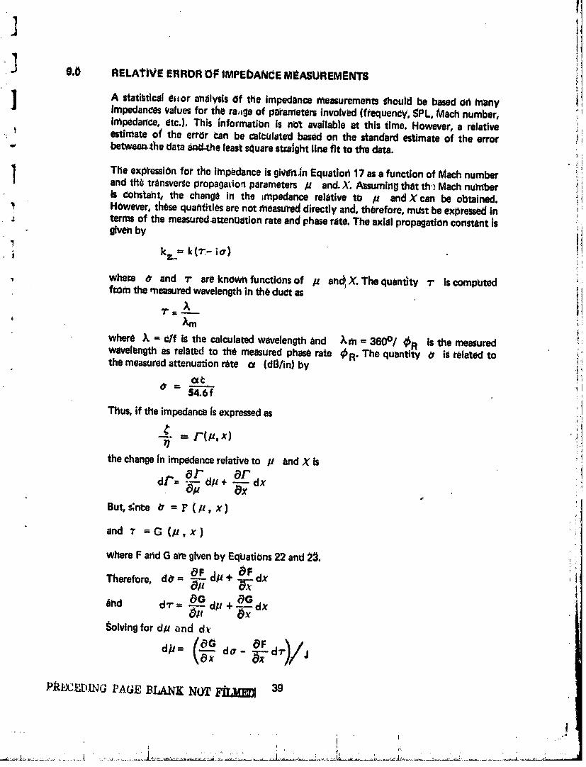
1-J g.O RELATIVE ERROR OF IMPEbANCE MEASUREMENT8 t
I A st4zti_t|ca_81for an_IVS{SOf the impedance measurements_hould be based oh many !IJ impedances valuesfor the ra,_geof pai'ametem involved (frequently, _PL, Mach number,
impedance, etc.). This _nformatii_n is not available at this time. However, a relativet estimate o_ th0 error can be calculated based on the standard estimate of the error i-.
,, betwee_he data _i_J-theleastsquarestcaJghtline fit to the data.
The exp_'essiOnfor the imp_ance isgive_n Equadoh 17 as a function of Mach numberand tll_ transversepropagafio,1parameters /J and. X. Assumirt_lthat th: Mach nu_lber Iis comtaht, the change in the impedance relative to p and X can be obtained, i iHOwever,thesequatltitlesare not measureddirectly and, therefore, mustbe expressedin '_
- terms of the measuredattenuation rate andphaserate. The axial propagationconstantJs _i
givenby 11
i kz= k(_- ie) _
, where O and 7" are knOwhfunctions of p an_ X. The quantity 1" iscompIJted i lfrom the measuredwavelengthin th6 duct as
where ;k =clf iS the calculated wavelength and _m = 3600/ _R is the measured Iwavelength as related to the measuredphaserate _R. The quantity 0 ill related to _the measuredattenuation rate ¢t (dB/in) by :i
l(x_: .i
54.6f i
Titus, if the impedance_sexpressedas
¢ - F(P, x)
the change {n impedancerelativeto p and X is
OF d OF
But, S;n_e a =r(P,x)
and T =G (/_,x)
where F and G are given by EqiJatiOns22 and 2_1.
OF d. + _FTherefore, d#= _-_ _.dx
_O _O_nd d_" = _. Up +-_-dx
,_olvtngfor d/u and dx
}'R£_CF__D[NGPAGE BLANK NUT F_ 39
I
d:.
O0000001-TSD01

dx = d_"- _- d
aF _G _F _t;Where J = _ Ox _ _p
The relatio_hJp betWeen d a and d_" to the standard est|mate Of th_ error ($E) forthe measuredValuesof phaseand attenuation Canbe obtained by consideringthe changein ph_l_erate and attenu_tion rate due to rotating the leastsqu_r__traightllne fit to the
data about the be_innirlgof the se_tion (__ length) by the _mount of the standarderrorat the end of that section.Thus,
• do'l == h (o_ - cx.$=) = 2h(SE) ?'(SE)27.377 27.3_ - == _'.3 ,_
dO,=_, h (_x. Ct.sl) = 2h(Se)27.377 27.3_ = 27.3
I
X (_;- _.s,I-- x(SE)= _-(SE)(:]'rl =" 36"0 - 1_O_m -
360
_ubstitudng the above formulas into the expregSioh for dF yields the requiredexpressionfor the error in terms of the standard e_tlmate of the error of the measur_lvalues of attenuation and phase. The maximum valueso_dr" obtained from the four i¢ombinatiorl_ _f dl- and do are U_edto represent the spread in impedancevalues, tGenerally, this variation w_s not larger than the symbol size usedto plot the data and, ]
therefore, is not presented in the dbt_ plots. The range of the relativeestimate of theerror i_ given in Figure 14 as a function of Mach number. This funCtiOn increase_withMath number indicating the increasinginfluenceof the standingwaveson the data.
4O
00000001-TSD02

leO ii
,dR/pc .5 ,, _
It. _0 .2 .4 .6
MACH NUMBER !!
.,j
.I
.!
i
1
CALCULATED RANGE OF DEVIATIONS FoR PI=_IFORATCb SHEET AND IiPOLYIMIDI: IMPEDANCE MEASUREMENTS _
FIGURE 14t
00000001-TSD03
i : i 1 i !
+
10.0 CON(_LU_IONS i
Consideringthe inherent limitations of the grazlrtgflow apparatusand the experiencegained in its ullage,severalareasexist that require modification and tmprovemerlt. Theyare:
4-.........The waveguideapparatus,as h now exists°should be redesignedtO reducethe standingwave component at higherM_ch numberswhich would reducethe variability of the impedance Measurements.Th_$can be done basicallyby improving the ef}_ciencyof the diffuser exponential horn bY a redesign.
• The frequency range of the apparatus c_rt be doubled by decreaSingtheduct height by a factor of two. However, the maximum usable Machnumber could be further limite8 by fully d_eloped pipe flow.
• The depelndenceof impedance on the bourn. ' layer profile"should bestudied. This can be accomplished by introduci_g boundary layer trips ofdifferent degrees upstream Of the test section. Boundary layer velocityprofile_ would be measured from which boundary layer mOmentumthickness and other flow properties could be correlated to acousticimpedance.
4 The impedance measuring te<_hnique can be improved by using twosimultaneously travetslng microphones. A "Fast FoUrier Transformer"(FFT) could be used to cross correlate the two signals to obtain theattenuation rate and phase velocity of the aCousticwave as a fundtion ofduct positlon. Coupling]this FFT directly to a computer would make itpossible tO obl_in directly Impedance v_. duct pOsit|bn. In thls case, itwould be possible,if necessary,to average impedanceover a certain ductlength rather than straight line curve fitting data over half wav_ length ductsections as required by the present measurement technique. Also, as aby-product of using the FFT, the power spectral dettsity of the entireacoustic spectrum would be available on demand at any duct location.Thu_, by making these modifications, more ihformation would be madeavailablein a shorter pedod of time.
I___.A higher SPL source is needed to produce SPL's that induce particlevelocities that dominate that diJeto grazing flow Sothat the grazlng flowirtducedparticle velocitiescan be determined.
The feasibility of uginga waveguidemethod of determining the impedance0f acousticmaterials in a grazing flow environtnent has been proven. This method deti_rmino_boththe resistivd and reactive impedances of the installed panel. Therefore, a realistidmathematical impedanl:emodel that considersMach number, SPL, and frequency cbn bederivedfrom this type of impeddncem_asfJrement.
PR_EDING PAGE BLANK NO_ P_
i:" .... i
00000001-TSD04

i
t
11.0 REFERENCES
1. Phillips, B. end MOrgan,C. J., "Mechanical Absorption of AcOusticOscillatiOr_sin SlmuJazP,d ROckierCombuitlonChambers,"NASA TN D,3792(Ja_ 1067)
i
2. Phillips, B., "Effects of High Value WaveAmplitude and Mean FlOwon aHelmholtzResonator,"NASATM X-1582 (May 1968)
3. Garrison, G. D., et al, "Suppression.of CombustionOscillatiOnswithMecharlicalDamplrtgDevices,interim Report," PWA FR-3299 (8 Aug. 1089)
4. 8inok,J. S., "BehaViorof AcousticResistanceof Typical Duct LinerStn thePresenceof GrazingFlow MeasUredby a Two MicrophoneMethod," M. S.
" Thesis,Universityof Southampton(Oct. 1969)
5. Feder, E. and Dean IIi, L W., "Analytical and ExperimentalStudiesforPredictingNoise Attenuation in AcousticallyTreated DuNs for TurbofanEngines,"NASACR-1373(Sept.1969}
6. Cremer, L., "Theorie tier Luftschall - Dampfung Jm Rei:htekkanalmit_¢hluckenderWandund desSichdabeiErgebendeHoch_teDampfungsmass,"Acousdca3, 249 - 263 (1953}.
7. Nelse_,M. D._et el, "Study and Developmentof AcousticTreatmentfor JetEnglneTailplpes,"NASACR-1853(Nov.1971}
00000001-TSD05

i
APPENDIX
PRECEDINGPAGE BLANKNOT _
47 _
i
00000001-TSD06

$omple No. I Frequency - fl_ i2,7_ Open _oa O 1000 ,:0.032 m. Ho16 Dla. G 12500.{J32 in. Thick 0 1450
Colo Depth - O, 86 in, li 16b0i_ 20ooMdch No, _ 0,0
Olin Symt)o! |st _|_ W,=ve|dnqthSolid rrdbo! 2nd H,,I!
_' _m ," _ il/'/" /
...,,,, 2KHZ "#*_ _/i '
t+ .,,'| / .
o t.:!
, , .,, i
u I. i_ ql......6"-" ......._t
"" #_ 0 i 0 i_X IlilliilliNleellll
beeeeel_oeh_ pel_,el_Oeee Ib_eeeleleee _I It* Ill tlllllli_lelillllellll uileeeeeeoeoe
u
mmm ,,,m,mm .mmmm bm_,.. • _1 e o
6i
IIO 120 130 i40 15Ct leo
8oultd Prelllul'o Livoi- dB
S&,MPLENO. 1, RESISTANCEAND REACTANCEDATA (0.0 MACH)J:IGUI_E15
i
00000001-TSD07

_ample No. 1 rrequenry - Hz2.7_, O_enAroa 0 10000.032 in. Holb Dldi. [3 12500.032 in. Thick A 1600
G_rO l_pth = 0.86 |n, 0 2U00Mach No. = 0.3 O 2500
Open Symbol 1st ltalf W,ivolonqthSohd Symbc| 2nd HaLL Wavolon_th
i
am,mR_l KHZ
oo_2KH _'
,2, /
i "*d "
" I_....._v• O . _D A • A.,_.,,_01_
• O Q
L O| oeoooeeooeo4 eoeeemqJeoe _ooeotooeoee ooooeoooooo| IJotelipooeooo oeeeoeeeooo| oeeoqeoeeeo| eete*e6eesol )eeeeooeeoeeo teooeqbeooooe4
0 0 -ii e 6 •
_oO & & &
" -I. A c3 A =
• • ( mI I I II I I
qD
"ailO I=O 03o 04o i_o ISO
$oultd Preeiute Level- dO
SAMPLE NO. 1, RESISTANCE ANI_ REACTANCE DATA (0.3 MACH|FIGURE 18
50
: ' ' ,,b
00000001-TSDO8
l- l ............. T -T!
,, 1 t ' ' i
Sore#reNo. I Freclucrnc:y- H_2.7_ OpenArea D 12500.032 in. HoE) Dlo. & LG00d.032 in. Thick 0 2000Ooto De_th - 0.86 in.
Mach No. '_O,_; Open Symbol lilt _aLf WaveLengthSolJ.d,_ymbo!2nd Halt Wavoler'_l|h
-v
..,,4,,,..QKH;_ .+._i m
B
' A&
i
O ' "
!
t
It
tu l, .......... ;X :, I 1
teeemeeeeoQ _eeleooeeee_ oeoeeeeeeoe4 eeoeoeeeoqtelJQeooeooeoeeebeeooeoeeeooeboeooeeaoeooe)eooeeeeooeeo_eoeeeoeoeeee_e;oooeoooooel I
8 O '
| .a: -L :- .; _.
E] r_ r:L ,,
I I I I
al
IlO i20 i30 140 160 160
8ound Preesure Level. dB ',
t
SAMPLENO. 1, RESISTANCEAND REACTANCEDATA I0.5 MACH)f:IGUI_E'17
00000001-TSD09

Sompl_ No. 2 l'rdquoncy - Hz4.47. Open Area A 16000.059 m. Hole Di_. 0 2000O. 03(} An. Thick
Coro Doeth a 0.86 in. _pon Symb_,l l_t Ilaif W.w_lqnqthSobd S),mbol 2nd H41f WavolorRtlq
Much No. - 0.0
"--"--6 ltCPIZ -- jp-
_..m.. 2KHZ _i _/
i :7ll, J _
| /I. , ......., _ j • •
/
_ ,.
3.
ib
,n
0 L '
I e4oo_ nNNHNm_, |OOoooeoeeooqatt_.... _t
| o & A --" """,
i I lummmmm I mmllmml t mmmmlmm m__. _
4.IlO 120 130 140 150 160 •
86und lbrouure Level- dO
SAMPLE NO. 2, RESISTANCE ANO REACi"ANCE DAtA (0.0 MACH) ' "FIGURE18
j
52+*
O0000001-TSDIO

Sample _fo, 2 Plllqumney- HZ4.4% Olin Aroa O 10000.059 In. Holo DIe. a |:_S110.030in.1%ck A 1600
Oor6 I_pth - 0.86 in. 0 2000
Math _o. - D,3 Olin Sym_o! lot H_[I Wavolon0tlsSolid Symbol 2ridAd[{Wdvelongth
m 1KHZ
0eeoNeeo 2 KHZ j
/--[;¢
I"' _ _ =mumm • •O
| • +&
• LE
r !
_ Lx
I
_ Ao & &
t--3, l ., I
I10 |20 130 |41) t_0 leo
_oufid PreliUre Level- dB
SAMPLENO.2, RESISTANCEANDREAC'rANCEDATA10.3MACH}I_IGURElg
53
..... !
O0000001-TSD11
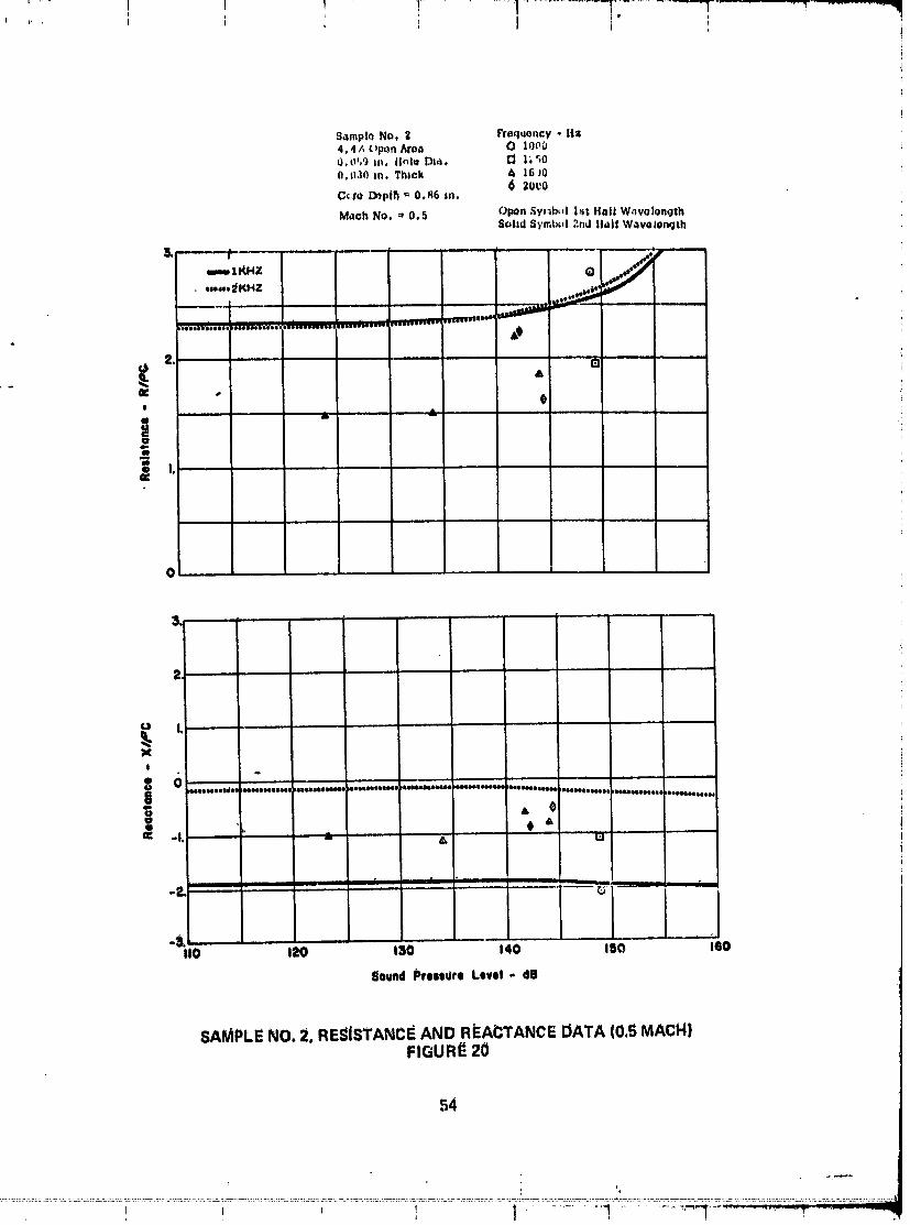
Sampto No. = Tr_qtmncy - It=4,4A ()port Araa O loPO0.oT,9 In, ll_le D=a. I_ l;q0O.0101n. Thick & ]6J0
0 zeta0Gem Dopjh _ 0 86 tn
Math No. - 0.5 Opon Sy_b_l [st Hall WavolongthSolid S'_'mbcd 2nd Hall Wavolonqth
_g i" ...... = = ,i ___
emm II_'4Z Q//d_
-.-,:[KHZ
2d m
E •
, $
g
W
X!
6 "_ , , ,i, , , ,, ,,,Jllll#Olll_|| Ol|ll|.llStOl HllloltliJll lilIIIH|O JlllllJOlllllO I|H|llililJl eOOOOOoOOOOO
OOql@OlO00Oe4 )O_g_qbeoOOoO
A et4t 4 A
O: -I. a, .....
, •ii i i i IIIL IIII
Lv
".o .=o .30 ..... ..o .=o " .6oSound _rns_ee Level - did
SAMPLE NO. 2, RESISTANCE AND R(EACTANCE DATA (0.5 MACH)FIGURE 20
54
L ',,
00000001-TSD12
• .;-:! " " ' '-"_ .....1 ............. ':-:_' I
Sample t8o. 3 Fr_quencw - Hz6.1% OFon Are4 O 10000,039 tn. Hole Dla. 13 1_500.032 in. TlUck 0 167|
0 2000Gore Dopth - 0.66 in. 0 2S00Mach No. - 0.0
Op,m Symbol lit Half Wavol_ngthSolid Symbol 2ndHalf W_volonqth
3. l ....
../....j,*_'_ _ 4'I
..._.,v.": /--"*""" 0. L......... _._41i1_111 illillli_llll ,
0 L
X
S o ...,,;......... ;,...., _ ............................. _...........;...................... Q....... ........... ..
g
41 O
-&t10 120 130 140 180 160
8ound Preelure Level - dB
SAMPLENO.3, RESI$rANCE AND REACTANCEDATA (0.0 MACHIFIGURE 21
55
! _ I , I 1 I r
O0000001-TSDI3

,5_mpl,_ No. 3 Pro_l.oncy - H_I_. l ,',Or,o. _ea 13 12_00,o.19 in. l-h_la D|_. 0 2o000,U.12 m, Thick I_ ,_40
C.,_,ru/X_p,t_ ." 0,86 In.(_pen 3ymt .l l'_t llJlf Wdvelonqlh
M,leh No. -- 0, 3 3. l_d ,_ytl_b_l ;;n,Jll,_If WavolunQlh
IZKHZ ]
-.0,,.*- 2 KHZ
!
.S.JI10 I_0 130 140 150 |60
Soundi_reeeueeLevel * dS '
f
SAMPLENO.3, RESISTANCEANDREACTANCEDATA(0.3MACH) _"FIGURE22
56
I ' ;
O0000001-TSD14
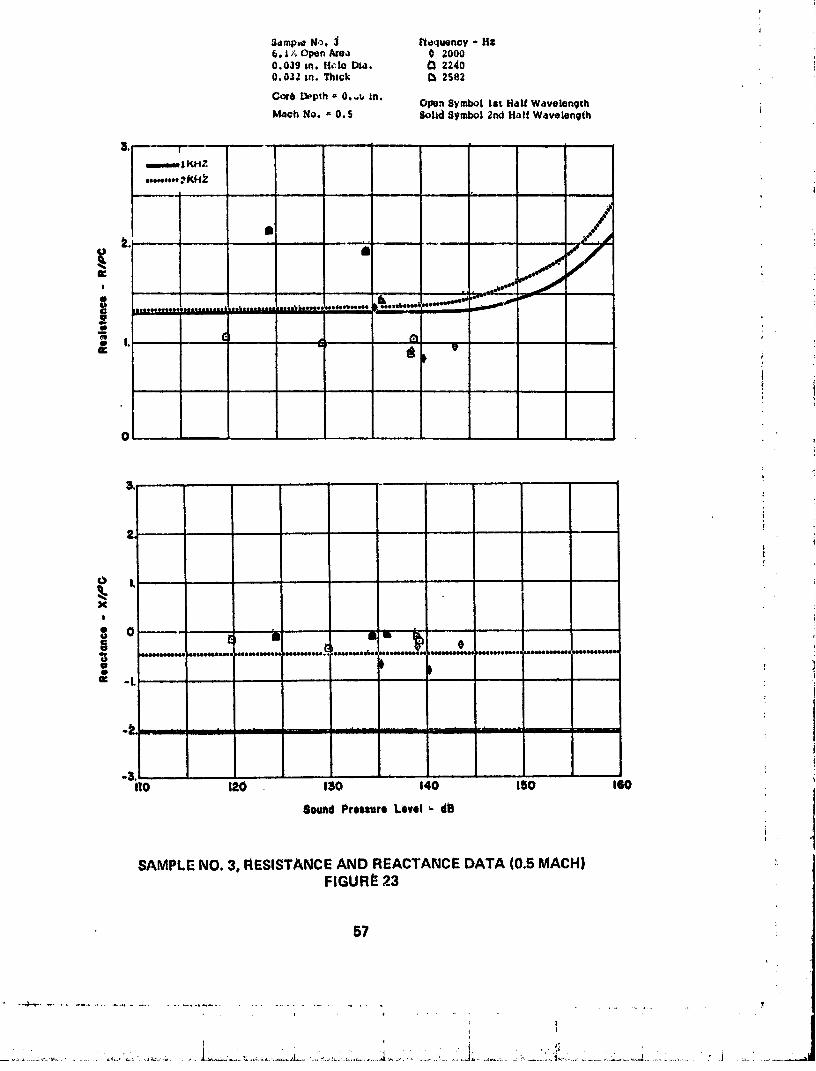
S_mp-_ N,_. J /'_eqtmncy - Hzb. I ;_Open _re_ 0 20000.03g _n. H¢,lo D1a. O 22400,032 in. Thick i3 2S82
C_'4 Depth. 0o,_ in,OIPQnSymbol ISt Half W4volongth i
Math No. - 0.5 Solid S,/mbo| ;_ndHalf W_velongih
umm.alKHZ
..........4KH _ ',
. /
TT_,';........ ;OeOeeeessss&,etbt*.o*_::= :=:_,s_';::=:*;'-*;:-_: -'_-:::-''-
O
O L
x$
., )Iz -L '
_. ............ I1"' " '" i' • .....
II0 120 130 140 150 160
Sound Pressure Level ; dE
SAMPLENO. 3, RESISTANCEAND REACTANCEDATA (0.5 MACH)FIGURE 23
57
-_' . T.... .. ,.,
00000001-TSE01

Sample No, 4 Frequency - Hz10,4"/oOpen Ar6a D 21000.038 In, Hole DIo.0.032 in.Thick
Open $ymbt_l 1st 1t,_1iW6velengthCof_ Depth =,0.86 in. Sohd Syn_b_|2nd H_If W.welongth
Mach No. _=0.0
I
m IKH_
,o.,**oJgKH_!
u L
X!
3 o8 m _
800800088000 Jooooooeeseo, 8eooeoeeoll_ Ioooooeooeoq)l.)oootooooooq rooOOeoo4t4m@l_ooeeeoooeeo_
teeeo41t6tlme4 oooeoteooeool _oo4Jooeooeell
(I *L
-3.I10 120 130 140 ISO 160
Sound Preuute Level * dE
SAMPLENO.4, RESISTANCEAND REACTANCE0Ai"A 10.0MACH) _FIGURE24
• !
I '
00000001-TSE02
S4mNe No. 4 frequency - Hz10.43 OpenArea O 21000.038 in. Hole Dla.0.032 In. '1"hick OponSymbol 1st Halt W4veiehgthCore Depth - 0.86 In. SoLd Syr_bo|2fld Hd|| W,_vo|ength
Ma=h No. - 0.3
I1_ | ,±1. ,,
mXXHZ
eV,.o_,02KHZI , ,,i,
o I
_ L
x!
i ,..0 B
oeeeoeseeeee _eoeeeoeeee_ eoeeeeeeoe_l heeeeeoeoeeq eeoeeoeeooe eMee,_eoeee( oo_eeloeeeee eeleoeoeneel L4meeooeoeee imleeeeeeeO •
i T ii
II0 120 130 140 150 160
Sound Preeeure Level - dO
SAMPLENO. 4, RESISTANCEAND REACTANCEDATA (0.3 MACH)FIGURE25
5g
00000001-TSE03

i I I ,
Samplo No. 4 rroquency - Hs10.4/o olin A[oa D Zlu00.038 m. Hold DI_.O._}32m. Thick
Opon _ymbo| l_t ll.ll! WavoiongthCore Dopth - 0o86 mo $ohd Svmb,.,l ;_nd H_i! Wavol_n_thMath No. _ 0. S
,| - ,
,,,,m, 2KH_:
., L,,
I
o L ,
X|
O _ _ _)
gg oooeoeeeoe(Jl eeeoeoooeeaq eooeJLmeemoee mmeooiDIeei_ oeoeeoeooeoe eLseoooeeo_Qq eooeeoqDleol DIsooeeoeooo looo_esee88 )eeeeeooaoeL
_: *L .......
( ITnII II r m " I
,I_3° . i .....
IIO 120 I_0 140 15(_ 160
80uhdPreoeureLevel- dB
sAMI)Li_NO.4, RESISTANCEAND REACTANCEDATA(0._MACHIi_IGURE26
_0
, .....................i...................." "":' ;".....:;i" ......
.J
00000001-TSE04

Sample Ho. _ I'requency * Hz_.9_; or_n Area 0 20000.1 in. Hole _a.
0.03 _n, T_tck Ol_n Symbol Ist Hal| WavelengthGore Depth a 0,86 _n. Solid Symbol 2rid _aIf Wavelength
lvl4ch No. ,, 0.0
3q T .....
,....,m4 K_cZ
•.**_-, 2 KH Z!
0
X
' 1= - .........*"........._"_.........................._:","--.6 ...........O el)oeeeeeeee Nl_eoeeeel m
)eo_ooe_
e
-3. III0 I_0 130 140 180 160 ;
SOund ISro0su_o Lovel- dB
SAMPLENO. 5, RES_ISTANCEAND REACTANCEDATA (t).0 MACH)i_I_URE 27
(;i
00000001-TSE05

Sample No, $ Frequency - l|z_.9_. Upon Atoa 0 20u00.1 In. Hole Din.0.03 in. l"hzck
(_p)n &y,nt>,l l_t il_l| W_v_lonqthCoro Dopth = 0.86 In, Solid ,_ymho! 2nd FI41! Wavoionqth
Mach No. = 0.3
mIKH;_
,--,_2KHZ!
0
u L
X
, !o 0o
Jeooeoeoeee8_ _eeeeeeoeoee_
" _ I I II i I I.... , ,, ,
-3.Ill) 120 130 '" i40 150 160
Sound Preenuro Level - _JB
SAMPLE NO. 5. RESISTANCE AND REACTANCE DATA (0.3 MACH)FIGURE 28
i
..........•.........L.......................i,.........................l........ ___:±L.,L_____
00000001-TSE06

_mple No. $ I_re_¢uoncy- Hz9.915 Open Axea 0 20000. | in. l-role Dsa.0,03 ArhThick
Open Byml_o|lilt HaI_Wavo|enqthCore Dopth - 0.85 in. 8,_lid $yfnbol 2nd Hal| Wavelenq'thMath No, - 0.5
I • . , 11 • ..... • -- |" " " II'l I I_ = .... " II u .
llO 120 130 140 It)O 160
8ound Pressure Level- db
SAMPLENO,5, RESISTANCEAND REACTANCEDATA (0.5 MACH) ._FIGURE 29
63 :',
00000001-TSE07
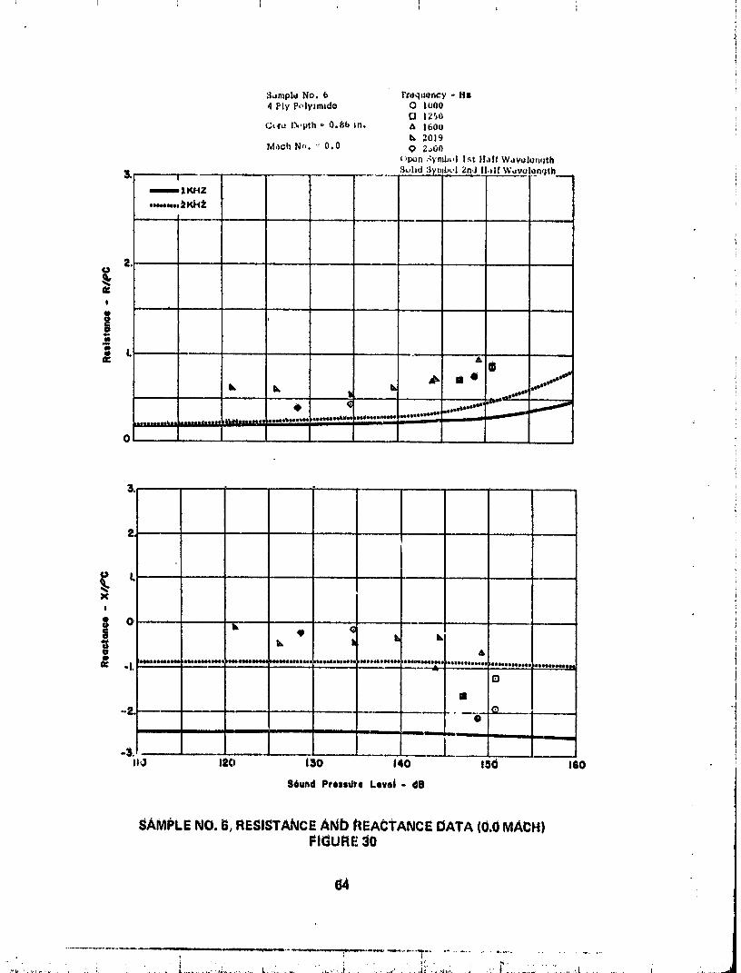
_nIpl_ No. 6 Fteqtz_.r.cy - Hs4 PIy P,,l,,,Jm_do O Io00
El 1250C_,rLJD,,pth _ 0.86 In, A |600
b, 2019M_JohN"_. _"0.0 q 2_,00
(_pon-lymb_,]Ist }lairW,wolun,lth_uhd 3y.lbu'] 2n,J l|,*{f W_*v*
l
XI
o
&
oe*,l,lo,oooee oHctoooeeoe b,oe.ooeooeO,l,, _ooeeoeeoeee, _,oe,oooeoeo¢ .o*oe*l.e.l, eoee _eee,,,****eee_ ee,Jeeeoo*ee,J Ioeoeeo,ooee _'................ ,
an
O-
Ill I I II IIII
1 -,._ t2¢i 13o 14o tSO leo
$6und Prendte Level- dB
SAMPLENO. G,RESISTANCEANb hEACTANCEDATA (0.0 MACH)FIGURE 30
64
•. , ...... ,.!" . . ,
00000001-TSEO8

_dmpie No. b Fruquoncy o Hz4 _|Y Pt_ly_mldo D I2S0
1600
C_t'_ I_.,pth _ 0°86 In. 0 20000 23100 2_00
Math No,, _ 0. J '"Open S,/mbo! 1st lla/f %Vdv@l_nqthSolid Symb_+l ;_nd H,,I+ Wavolonqth
3. J,n-.---- l KHZ
•o,4o.... _KHZ I "
t i .... i
mQ |l ' " '
o i
1_q ........
I
_'_ L ' • ' [ - '
X!
0 e*,.:, 6_'_ '' c 'gQ _O0_I_O00t4JQOOe4NJOOOQI o_oeooo_n_o Joeo_Qoelmeo D(toe_6osaeo_ leooeeo4Niol. _ _oQe.(J6soooeo soee,l_,_ootj le418oOeooooel meeoemtne6,I1_ °L ' .....
E
1
........ ' " 1
!
I _ I I I I t
"_iio tJZO l_o o4o tso teo
Sound Preeeuro Level- dB
SAMPLE NO. O, ,,ESI_TANCE AND REACTANCE DATA {0.3 MACHt_IGURE 31
85
.o
00000001-TSE09

5arnplu No. b l'ru_lut'nc_ - llz4 Ply PolTimido Q 1250
lt,0uGt.,r_ L_pth = O.Hb in, O ;_t_llll
M._ch Nu, = O. _ _sp,_n ._;ml,, I ]_t il,,If W,ov,:l_.qth.SL,hd ,;s'mi,L'l _.l_dH._I! W ,v,:l_nqth
""""' 2KHZ---
!o
i| I.
q qP #,o.'***_
,, .
o L
Xt
| o I, °"= '" 'o" _e4oeooe,ob*oe beeoibooooooo_ _eooeoeqJoooo, ,o4mabq.xm4eoqoooooa_oee_ _q_o_moooa ;e6eeoeooq_eel I_ enseeeoe,L : = :....... ._n
ii ill1nl I I II
rio ti_O 130 i40 " 150 160
_ouhd Prossure Levol- dB
SAMPLE NO. 6, RESISTANCI_ AND REACTANCE DATA (0.,_MACH)
FIGURE 32 :
66
i q
O0000001-TSEIO

8_mplo No. "_ Frequency - Hz8 Ply Polyimid,= 0 L250
A |600
Coro D_pth _ _ .SG in, o'17820 2500
MaCh No. _ 0,0 Open Symbol ]_t HJLf Wavelength$ohd Symbol 2nd H_I[ W4VolenrJth
O ,,
I r
"=i=o IZO. i_o 140 sso ' =60Sound Pre=eure Level - dO
SAMPLE NO. 7. RESISTANCE AND REACTANCE DATA (0.0 MACH)FIGURE 33
67
00000001-TSE11
|
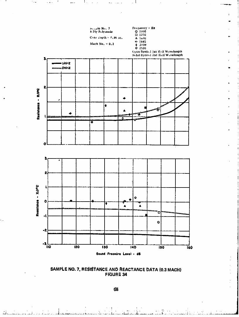
a,_-..#l_ Nu. 7 Fr,Huenc_, -HI¢I_ Ply P_ly=m|de O lU00
I_ 1250 t.C,,ru D_pth _ 0.19_ in. /_ 1_00
o 1=345M,_ch No. _ 0.3 0 2000
O Z500
open 8yrnb_,| l_t }(,dr W,lvulongth ,:_l|d _ymb_l 2nd l[41f W_volonqth
t
=---, ¢RHZ....... _KHZ -
I L.
o
8 A AleIooeeoomel ,beemoooeol °ebooooeuoa °OO°_°I Oeoooeeooeoi l_eooooooe_oi ee_eoeeoeeee
gJoe°co°e° _ _oeeeeeoeoeoe_'°eeeeeoe6°o°_
E -L I ,,
®
i i i / il ___ _
I10 120 130 140 |50 180
SoundPreledro Level- dE
SAMPLENO.7, RE$i_i"ANCEAND AEACTANCEDATA(0.3MACH)FIGURE34
68
O0000001-TSE12

S_mplo_ N,= .' i'to,lu_nc7 - tl_8 PW P,,W*m,,I- O l_a)_)
C'c,t'o _pth 0.86 in. ¢, 1600,4 2O72
Math N_. ". 0.5 O 2300Opt_n 3¥mbo| |st H,H| W4ve|onqthS_l|d _ymhJI ;:ridtlalf W4v_llunqth
m| KHZ
-,--- _KHZ
O , . 41 ....,d ,
........ _ : _ ......... ",(l_ Illl-- IIIllir IIIOll.O01tlI(
i L ',0 ....e
EQ
0
_ L LL _ ,L • ' ' ,,
X
o0 ...... " _ = e _. _ ...
• AItlltiltllll llllllStlllill rlllllllllll IgllIQIIlilltl iltlllltlllll IIIllllltllil illittlllltl IlitlllltB_ iIiiNti_l_ IIIIIIllllll_
e= -L " _v '"
]
I
o_.llO 12() 1_6 IqO 150 I(_0
$0ul0d Pre|eure Level- dB
SAMPLENO.7, RESISTANCEANDf[EACTANCEDATA(0.5MACH)FIGUf([_35
00000001-TSE13

_umplu No, 8 rlo.luoncy - Hii2 Ply Pt,l.,smido O ]uO0
r-. l ;_._,0c,.ru L'k,pth : O,H(_ in, _ |f,2?
¢._p.n ,_ymt', I l,_t t! =It W,=v,_l,_==.Tth,;, 1|,1 .5_mt_, I _';, t II.,l| V_'.'ol,l,l_,Jlh
t .... ,.._...,/-_7
i._, t, ,..-- 1j -7,7" '"
!. .,- , .. . .,.
5.
X
, 0 0
_°eoeUoeoee _
il m *'**'*"*".,O
@ Q
"=hO ' ,=o ,3o ,40 ,=0 - ,-eo "
Sound PreUU*_o Lov,I - dO
SAMPLE NO, 8, RESISTANCE AN0 REACTANCE DATA (0,O MAcH)
FIGURE 36
¢.
7O
i : q" .
O0000001-TSE14
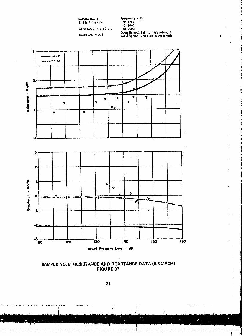
Sample No. 8 _oquoncy o Hr.12 Ply Poly_de V 1765
6 zoooC_lro Dopth = 0,86 In, O 2500
Open Symbol 1st HalfWavolengthMach No, ," 0,3 Solf,d _ymbol 2nd H_IfWavelenqth
emmmm1KHZ //
,,...f4 /!
' ..... J_'- ._
.........._. .....................,..............04esooe _O4_N
e
e ..... • # • _;'
ao |._ V V
0
"&lib 120 130 140 i50 160
Sound Pressure Level- dB
SAMPLE NO. 8, RESISTANCE AND REACTANCE DATA (0.3 MAC:H)FIGURE 37
71
t
00000001-TSF01

S,,mplo No. 8 frequency o HZ12 Ply Pc,lylmlde & 1600
o 1945Cure Depth = 0.t16 in. O 2500
Opon Symh,I 1st H;,II W,_v_lonqthMacrl No. = 0,5 S(_l|d S_'ml,ol 2nd Half Wd'/olenqth
-1I10 ItO t30 140 150 leo
Sbund PJ'esetJre Level - dB
SAMPLENO. 8, RESISTANCEAND REACTANCEDATA (0.5 MACH}FIGURE 38
72
! i ; :
00000001-TSF02

S.implu Nu. 9 Vruquency - H;_i6 Ply P,,lylmldo (3 1250
lbO0C_re Lx,pth _ 0.86 zn. L_,)n Symb,,l ]at H_ll! W,zvalength
Sulld Symbul Znd H,zl[ WavolonqthM*ch Nu. ,- 0,0
6, i i +-
BZI_HZ
• //
, ,.,m.mmm mmmm, _ .,_ ''_ '
Jr,, , 4k
L .... 4_1411141_iII14mi10 _II86110elNI4011 4_ +_141ellOlml
1101101141111 +04NI_144114_II IIIIIII_IUI01Ol.
I _eeeeeeoeeeoe
rlee_eeeel._
S O. a m .....8 • • m mm '_
Ig °L
I10 120 130 140 150 160
Sound Press+ere Level- dB
SAMPLE NO. 9, RESISTANCe. AND REACTANCE DATA {0.0 MACH)FIGURE 39
73
i I
00000001-TSF03
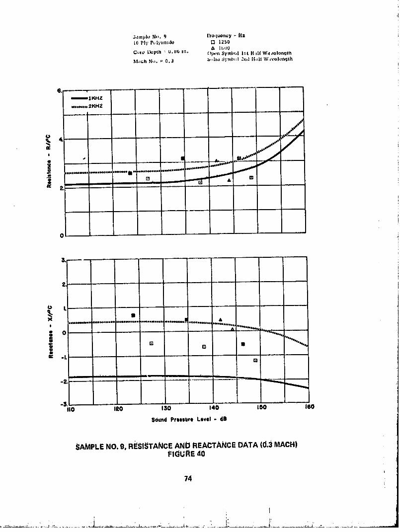
3,_mpiu N-. 9 ['ro,luoncy - Hz16 Ply P_,l_,zmido t_ 1250
I|,tJ0
Gut4., L_pth _ u. tJb In. Op,.,n SymbtA l_t H.tlf Wd,,olonqthM.ch No. _ 0..] b,,h,_ Symt,-! 2rid lt,t|t W.J_,'ul_nqth
mlKHZ
.,...,. 2KHZ
/o ....t ._• . , , ,,._. .
$
e ". I A. .,, ,oU'_#"#U - " _"
_,ee_ ,,,,,,,,,_.,o,m,i _ ..,.,,,,.,,,__uto,*,***'.,,,,o*,*'**'
, • ,, , ,
0
I_ L , 1,, , . .
xJi_ _tJ_OS88e, |ooeoo4_eeooJ,: )aet_tms_1)lk .Jee_tese_eeJ d_
, ...... ""*._ ,.,,-.....g o .... -- _ """"" "--
-""eoee4leeI8ra • '*"*'*.***.
a, -LEl
.o leo ,3o ,4o mo leoS6und PressUreLevel - dS
SAMPLENO.9, R#$1_TANCEANDREACTANCEDATA(d.3MACH)FIGUP,E40
74
00000001-TSF04

i i i
$_mpL,J No,. 9 Frbquel:cy o HzL_ Ply PoLylml.d_ Q |_Su
A |600Core L')opth = O. 86 Ano 0 2000
M_¢h No. = 0.5 Opun ,_ymi_ol ]_t H,_II W_lv_ionqthqohd 3ymbu! 2rid Hdlf W_velonqth
0
$
o L ,,
Xe
b i
0 " " ; & '°"*e°°,,,,,°°
_ Ir_ leeeeeeeee,°e4
iii r ....
°_,,
I10 IP.O 130 "'"140 150 160
SbundPressdre Level - dD
SAMPLE NO. O, RESISI"ANCE AND REACTANCE DATA (0.5 MACHIFIGURE 41
00000001-TSF05

.-;.,mpl,. N_0 I0 Fr,J,luuncy - HZPly P, lYtmlde {3 12_,0
& I t_l_U
Core D_pth = 0.Sb m. 0 20000 2250
Mdch Nf).= d.0 O 2500Opon S_'r_lb_,Il:_t HJIf W,welonqth
_, , ,................ S_ohd :_ymb,.l2nd H.HfWdvol_qth
--'-"--IKHZ
i
0
[
I I _ t "
I12o e3o t4o tsO mo
8ound Ptessurb Level- dB
SAMPLENO.10,RESI_i"ANCEANDREACTANCEDATA(0.OMACtitFIGUI_E42
76
00000001-TSF06

; I
t
I
_dmp]- l_,. 10 tYoq_ncy - H_6 Ply P_lyzmzde Q 123o
1600 tC,:,ro _pth = t).lLb m. (_ 1850
O 2000 iMachNf,. _"0,3 • 2250 f
O 2500Open Symbol lSt H,zlI W_vol_nqthSohd Symbol 2nd H,,|f W_vulonqth
}. ..... T ........... ; ...... " " " "
•....'." _KHZ=
L! '
J
•.......o.. _ ff..,.a_-_.....,_:_="'w"-_°_'x_'"_ m._ I "
I
r,
• , ,r , I I Ir
"sit{) t2o 1_6 140 "' 15o leO$ou_td pressure Level- dO
SAMPLENO. 10, RESISTANCEAND REACTANCEDATA (0,3 MACH)FIGURE 43
77
00000001-TSF07

; : 1i
:_,_n'.ple No. iO I'ra,lUelbcy - !!7.G PI_' P_ly:mJ.do I_ 1ZSO
]GO0Ctr,_ I)upth _-0.86 In. 0 |LISII
0 _oo(JM.ich No, _ 0.5 O 22:)0
O 2_uo
(Jpon Rymbc,! i_t l[,llf Wev_lenqth_,lsd S_,mbc,I 2_,J lldl! Wovol_ngth
-"_'--IKH2
0--..- 2l_qZi
2, ""
,B
I, - . A " ---_o"°'°'J"°'°II
ew
o
2
!
| ° ; °% •A A AE)
4D )meeoooel oelNiooeoeoeeeoooeosoeeaelDoosooooooo_Deseosooeoeoajoooee_..AoeeJeeoeooeoeoe Ioooeeeeeel0o _t.._,oeeleoeoe-- )_oeool_ooes_
-L • n
I I Ul ilil
I10 I_0 130 I 4i) I _0 160
Sound Preeeure Level- dB
SAMPLE NO. 10, RESISTANCE AND REACTANCE DATA (0.5 MACH)I_IGURE 44
78
00000001-TSF08

i i l ;
3ample No, 11 Frequency - Hz6 Ply Polytmzdo O I000
O 12fi0Cc,r_ Depth = 1,4 In, _ 1600
0 1850MachNo, =0.0 0 2000
Open Symbol 1St H,Ilf Wdvol,mqthSolid Symbul 2nd H,=if Wdvokmqth
==mmI1 KHZ
euul, o=*2 KHZ
_e
2,
A 0
= c _e " $*e ...,,.""' "i IlIllllllllII _i_'III I_ll_ IllI =__ _ll_l _'OIl_l_tql_
....
0 L
x
i 0 "_¢""" "" ............ = ................... J'-....=_ .......... .,mmr.T._-, ..................1_leeelta .......
.. ( El Iu I i
= _ o • "oE -L •
*3,I1¢) 120 130 140 150 160
8ound Prt.lsure Level- dB
SAMPLENO. 11. RESISTANCEAND REACTANCEDATA (0.0 MACH)J:IGURE45
79
, _ , • ,4
00000001-TSF09

Saml,Iu N ,. I Ih rl_' P..lillllld,J l'r,J lU'-:h_'i " II_O I llllil
Q I_,0C.l,a l'_'l_th 1,4 In,
M,Ich No. " 1.1,J 0 L.OOO
i p,Jn 3yllll,_.| ._11 ll.ll W,Iv,Jl.nqlh,qc.,lldSyml._,l _nd lldl W,.ivol,:r, iU1
e,mmm 1[KH_
**-*-- 2KttZ
|I | -- "'*"
m III *
__*....._w_ _....i,__......_**';....W...........,,....:iI_ _..."""
L "':
X
' • * o_ q_ _w
_i iii oIII o |e • • • ®GI
-L " "I I II I
IL_
t10 II!O 130 140 I SO 160
Soud_ Pressure Level- lIB
SAMPLENO. 11, RESISTANCEAND REACTANCEDATA (0.3MACH}FIGURE 46
80
0000000"I-TSF'I 0

S,mpI,J No. I ] Tr,lquuncy- il_ I6 PLyP,.Iytmtde 0 ILII)U !
O l_'}u
C_.r_L_pth ,. 1.4 _n. & lt,OO i0 iesO
Mach N_. = 0.5 0 2000 i
Open _ymh,.l1st H,*II W_,vub:n,lth !3,-,hd.'-;_'mb,.l;_ndll.d!W,w._l_Jn_j..h
_| KHZ
..........._ I<HZ
]2,8
g I..,,,,,,?,,, --"""
i '. , ,_l 0 _)
i .......
L ....
b '""......._e................._......_,....A.,..-..,,_,...,,,...,=._._.............._-_.,.,. ........
• _) II 0 • 0 "
IIIII
-I
al_, . .
llO IZO 130 140 150 160
_oun8 Preclude Level- dB
SAMPLE NO. 1I, RESISTANCE AND I_{_A{;TANCE DATA (O,t_MACH)_:IGU_E 47
81
00000001-TSF11
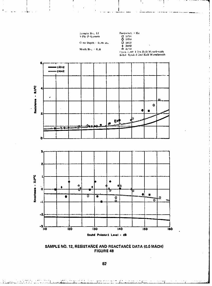
;_.mpl,_ Nu, 12 rt=quc, ney o II.;'_ PI_' P,,l_'lmJdQ (3 l?..r_*=
0 n4_oC,.rq [_pth ,- O,HI_ In, 0 |HSO
0 2_JO0
(_l"-'n :;'_mt_,/ I_t II,HI W,_vebo0;fjthSeth4 S)'n=h_J;_nJ II,_l( W,welon¢lth
"','" 2KHY
llililt lilt itllllll iii1_
I10 Itb I=O 140 I=O 160
8ou_d Pr6sllU_ Level- dB
SAMPLENO. 12, RESISTANCEAND REACTANCi_DATA (0.0 MACH)FIGURE 48
82
O0000001-TSF12

I 1 ....
,"1_mpl,_No, 12 rr_quQncy- Hr. :'g Ply p4,1ylml,to 0 14_U
A lbO0
c 1_ L',_pth= n.eO m. 0 2000 'i0 2_0
M_lCh:_';, "- 0,3 Open ,'_wnh-I lit t|,,ll W,_vol._nqth 'il]olld _ymh-| 2rld tt,11{W,Iv_lq.:n,jth "i
_1', F...... 1 -- _
l
]mlKfl2......_ . ._KHZ
oi
, " • ,_r j
o • ....W•, ....,, :"_ /eel _
._ " ol-"....._ eO@
,_.
L .....x
80 ¢g _ ,.o........[...,o..........• ............o.... ,...._...._eeelleeeelq_eeleeleee_e |eeelleleeel
_,.................._ ol, "......
I II i II ii ! I
"_, "...... ieO110 120 130 140 150
$o_nd P_eooure Level - dB
SAMPLENO.12,_ESISTANCEAND REACTANCEDATA(0.3MACH)FIGURE49
83
. o, .-
O0000001-TSF13
t T Y T !
P
i
S,.1,pl_Nu. 12 l'li.lu.m_'- II_+JI'I'+'P h'_mld_ _ 14'.f' •
|t,.u I
_l,l,, |l(,plh - I).H( III* [} |l+_)(l0 +mljUO /7.',_] f
M,,cl+No,.- u.5T
S_,h_t:J_'mb.,i_is,ill.*llW,i'/,_'|,#r_,Ith |.+
_+..... u ........... [im,mm, l KHZ
--,o,o,,,2l_Z
/J .
iP,
I+_0 boeeeeeoe _e'ee
$ .=..L ._,,-91) ,ooelleoel-l_ lll_rlillllllll ,li811eolelle( It ,eellllj_eel lel+e4ejeeeee _ _ +_ _
c I I P
o ,_6 e -
o.
$
!o .... +..+............................• .........._..... "; c_IP t_ lllle_le'I°_ lleelleolleOlhl
III iiiiii i ........ ,.&.....
IS+.o 0so 13o t4o t_o i(;o
Sound Pressure Level- dl_
SAMPLENO.12,_IESISi"ANCEANDREACTANCEDATA(0.5MACH}FIGURE50
B4
. . , : . . , , , . : ,
O0000001-TSF14

• _mpIL_ N_,. 13 l"l'O,luone; - Hi:9 PII' l',-.lylmlde '_ 1300
O 1000
Cor_ Depth = 1.4 in. [_ 1250& 1600O IH:,0
M_ch N¢), - 0,0 Olin Symbol ist H_|| Wlv_lenqlhSolid Symbal ;Ind Half Wdvelenqth
E. 1........................ II
emmm4 KHZ Ie_,oueet2Kh Z
L-- l l l II
i
i -
0
1
iI
1i
tt
b • 19 131,
4MI4NNb@4111111_I4NI411HHNI_4111illbll.llllllllll IIIIII[IIIII Iql4Nbg4B,l14[lI III_N_i I III_O4111QllII I illll[ IQI4ll ,IIQI4NIIO411HIIII, lilllll_ ....
ue O ; u ...._:_,-_:._ := l •o II 0o o ,_.o • • _ i,e • -. i
"SilO izo 0sO" t4o lso as(>Sound Pressure Level- 1113
SAMPLE NO. 13, REglSTANCE AND REACTANCE DATA (U.0 MAI_H) :ilFIGURE 51
8b
.... " _.__._._._L....j...... _ .... ,'_--:_L._..'..."....
00000001-TSG01
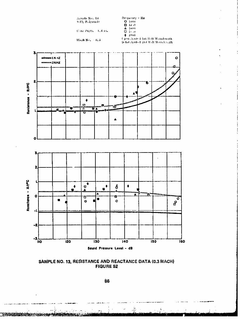
,;.:.pl*J Nu. |_ i're,I;lo.'_cT " HZ_ PI_ P,,,l)'_;zlsd,; 0 ILI.LU
A | I,|i(I
M,lch N.'. " O. J ('p,'n ,;', f_;t., | I_;t ll,,l! W.,:'_|,_n,;thLh*h,!:;__il,,.l.'n.l11,ItW,t'.'_,h_'v,;th
I_,,m. I K-tZ
'........ 2 KIIZ
_" _ 6 ...,_..o ..
,."........ .;;-.....u.-,...._...-._;...,e_. ,. -_..... /
A
0 " '
o t 0 '"
UIlls IA, ...,,.... ,..o....,.....'r...... Imeeeeee |_,@eteeeoe@s _em_eeos° ,e@eooeeeooee )• A ..... "_" ;'- ........
"' ° '" ° e*u
_ .|. - ........III
-3.II0 IA0 130 140 150 160
Sound Prissure Level- dB
sAMPLE NO. 13, REglSTANCEAND REACTANCEDATA (0.3 MACH}FIGURE 52
86
00000001-TSG02

S_mpl,_N_. 13 rreq_uoncy- tt+"9 PI_"P,,lyzmJdu 0 1000
IZSOA 1600
Cc.ro Dopth _ 1.4 sh. I_ 18_0O 2o00
Math N_, _ O.$ Op0n Symbol |_t _|,_|f Wdv0|onqthSot|d Syml_| Znd H_|f Wdvo|onqth
mulm_.l KHZ
.o,eee. 2KHZ
2 "' _.**- I_"
, .. .......... -...... ..._., _,..'_"._.-"_'_. ...........-:::+.-...:-.:_°_
I.
o L
'< _ ,+..'.l 1141141410111001jlellllelleetlll ,lelllOlllle _114 041 1141elll leellloeoe_o4 411d_ 1141
•' 0 , *u o u m ..... q,,"'o_'"" .......c Q II ® •o 3
-3.I10 I_0 130 140 150 160
gouna Pressure Level - dl_
SAMPLENO. 13, FIESISTANCEAND REACTA,_CEDATA (0.5 MACH)FIGURE 53
87
00000001-TSGOg

_.mpI.JN'-,.14 l°l_,_uu.c'_' .HT.|2 PI)"PL,l./imi,Ju 0 lq._.
{3 I, ,-
C..ru Depth 0._6 in. A 16,40
0 :,jtj,M.3ch No. " 0.0 ('I,'-'I_ :)'t i.t, '| l_:t ll,,ll Wavu_nqth
5_._hd3'/|:d,' I _hd [| _If W_ve|_nqth
mlKHZ
.'-.-.*21_-IZ
) e _ _...,
. ......._............" _.......... _...f_L ......---. ....'''" _c_
-4 ,3 ,f3 TT,--"
i , , i,
A
X, t ¢ tiI o ............'.....""........'_;....."-'-'_:e_"-'_" .......... 's , " ,_ • " _",.......*"'"_"....
_ _ '°eOoeeeeeet, o _e4'°eoel,oeeolJ &o _ A
d o
U0 120 130 140 150 160
Sound P_eleure Level o dB
fiAMPLE NO. 14, RESISTANCE AND REACTANCE DATA (0.0 MACH)FIGUFJE 54
88 _
00000001-TSG04

;-i,lmplug.. L4 I're,,luoncYo H_l;_Ply P,,15_nt,zdo ,"i 13_o
& |bmJ
C_ro D._l,th - 0.86 _,n. 0 1_'.,00 20,mO 22"_o
M_ch N,,. " 0.3 (-)|.JnSylnt,c| l:_t t|al| W,tvelqnqthSolid :ivmb.,l 2nd ILdt' Wdvolun,jth
_IKHZ [i,_.__ /"',*,.,,2kt IZ ..,.'l/
.........Z............• "," '"'"""_"_'"""'_...."_"_"_"'-u b0
_. L ,,
_ |o '" " '"
x O I 0, #meo • e
• 0 *_ .....
o_ .......................... _, ._z_-_ ..........A_ ....... _" _"_ ........................_Ai _ f°l'l'ee,eee j¢ -I.
-3. iI10 120 130 140 150 Ib0
Sound Pfetiure Level - dB
SAMPLE NO. 14. RESISTANCE AND REACTANCE DATA (0.3 MACHI _ 'FIGURE 55
89
00000001-TSG05
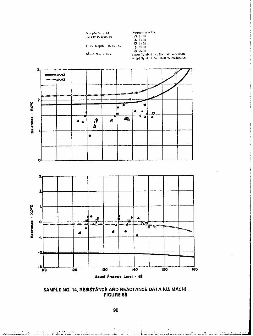
:; ,.,1'1'* N,,. 14 I'Tu,luullcY - 11?.lg I'l'f PLlS'lm_Ju ?'1 | Igl|
A Ib1_O
(:,'fu l_pth O.Hb in. 0 2(_LIN
l_._dChN,,. : 0.5 Op_.n 3Yml_ | I g;_|l.ill W.v,;l_.n_Jth_b..hd S)'mbt | 2lid lld|l W._vulonLlth
mIKHZ ,,,@/'0'"'" 2KHZ @_
........ A _.._ - !
o= a " t._, 4 l ,'"U a _O a
4)
o L
X
, • # •
................., '_..............._,......._............_.,_.._...O Illl@lltlllll IIIIIIIIIIIt_ I
.........
at d 4, ""...... '.,• d¢ -L
m mmm,ammm, mmm,_m -mmmm _ _'m_m,mm
-3i10 120 t30 140 150 160
Sound Ic'tessurl L_lvel- d_l
SAMPLE NO. 14. RESISTANCE AND REACTANCE DATA (0.5 MACH)FIGURE 5_
go
, ...... :. ....... _ _ i . . "." . . , ' .::_"_
00000001-TSG06

$,0mpl_ No. |$ Proquency - Hzi_ p|_. Pc,ly_,m_du _I U0O
O 1ooO
Coro l_pth = 1.4 In, 0 1250& lGn(}0 IH;O
M.sch No. _ O.0 opun Symbo! I:_tH,df Wdvo l_wjth_q_,hdSymbul _nd ILIHWuvuluh.qth
(_.
KHZ
n,e*****2 KI'tZ
O
4, .... • a.,
& ..,
........m.,........._L v....._ ....._"
o I. ' g .... m A @
eeeeeeeeeeea)(le_eeeeoleee i(lee_eeeoeeee _eee(beeoeso_ _eeeeeeeeeeellle _d_oeeoeose;'oeeeseoeoee, teeee,ileeeeoeeX •
| (lee#eeee_e#_
0 n E Q E]• eeeoeLp_e_t4 • e
De q
- I. q'_"_" _'_'q""
00o _o 03o 14o 0aO e_OSound Preseute Level - dO
SAMPLE NO. 15, RESISTANCE AND REACTANCE DATA (0.0 MACH)FIGURE 57
g1
00000001-TSGO7

:;,impl,JNo. 15 Fr,..qu_Jn¢'y- llzI,:Ply P_,I/_m6du O hJlJu
13 I2SO^ Lt,oO
t3,.,le_'p1.h- I.,Im.
M.iCh NL,, _ 0.3 , _I,,._, ": :r,l | |_,t il,1|l V;._..,;i,m'_th
_mlKl-(_ . ! 4}.. 'Oq • "*'OCY..o *'*_ .L
...'...................................- •;_;''il_'''...,_i_,i0,o &
o L
0 L ,
_. , .,. ,
..........., ...... ...., .........,_,) 0
.......'_............"" '"" _'".........._' 'w"".....e & & A & t..,.....o... I
o - _ - Q "_ II8 o o
-L " ' I ....... _' - ' ,r--"_____.._,._
I..........................
-3, J ......ItO 120 130 140 150 16t0
Sound Preeeute Level - dO
SAMPLE NO. 15, hESISTANCE AND REACTANCE DATA (0.3 MACH)FIGURE 58
9_
00000001-TSG08

8dmplv Nt-,. 15 rre.lu..,ncy- H=12 P|'( F',,I_';,_,|_ 0 1000
13 12_0lbO0
L_,.ro Depth _ 1..1 In. 0 Ill300 20o0
hi,,chNu. _-O.5 ("1_,n_ymb,.,l]st, HuH W,tvolon,lt{_Solid S_.mL_l 2nd Half W ivolon, lth
=,,is= 3,RHZ ,,,t" " '/
' ...... "2 lv_4Z l//
2. ....... )_-.,
' i nl. r_ %
n. Q@
0
_.,eeoeceeee
x ,........................,..........,,¥.....o.,.,.,.........;_........ ,, ..............,............0 _ m ui r_ 4 `0
o oo
-3I10 120 130 140 160 160
Sound PresSure Level * dE{
SAMPLE NO, 15, RESISTANCE AND REACTANCE DATA (0.5 MACH)FIGURE 59
93
00000001-TSG09

._,,;,q,l,J F;,. It, l'=a:.l,J,-'t,e;'- ilzI 3 PIT P, l'_At=.,lu _ am,
O Ira.,
C, rQ DJ|_tl| u0fl(, .i. A It,,),,O lh _b
M Iclt N_-,. _ 00_) _ t,-m .;,_r_l I l;;t H 1: ',%,av,Jl_httt_:_,lh|_'tml'.I _nl l!=II"_'_.,V,_J,#h'Itlt
,
=mmemIKHZ "
l & 0o "II A ..,_t
== : "" -- i.*
E ,...._,"_"_"_. , _ _..... ,.......
a O _ n
0 I, "'
--'q" U 0_J_ eeeee$sesseea oteeeQoeeoee _oe*ee_oe _ _eee4eoooe oee A_to4e_e 0, .....A..................';r':=',,._1"
e$_eeeeeeee
'¢ -I. ; ¢, o: _1o
t t t qil
-3, .. .1 . . J....I10 1_O t30 140 I SO 1150
$odnd Preseute Level - dO
SAMPLE NO. J6, RESISTANCE AN{:) REACTANCE DATA (0.0 MACH)FIGURE 60
94
O0000001-TSG10

5ampl_ N... lb rr,_qq_ncy - lfz|a Ply FulyJ,msd,a O ltl0ll
_} 1350A 11,t30
C, ru I._lh = 0.14_ In. O IH_0
e,,1_¢nN ' 0.3 i pm :hmb, l l_t IIMI W iv0|onqth8_,lld 8yml.,I 2nd If.dr _h iv.:,l._nqth
,._---- 1KHZ
ooooo..,3Kt,17
U ,
y® . • .... ,,,"
'_0Cu ---- i ................ o see°*°** _'_s°''*°_°°°°=°*°"°t*oq'_ _'b_°'°a't'°'°'_"_/"m_ ........ . ........ ......... .. ..... .... "i_ v &
, ...... I i _1'- it,-_ "_
• _J at
&O q
t
o t
3.-- !
o L o0
' "*" ................................' ;...... '_........... _ '"'"'Oe....., _ t _................ ._
o_ 0 0! _ * Illl A f_ "- '.,o,,,,.%_.
e 0 ,elO: -L _._ ---
It0 I:_O 130 140 150 IGO
_ound Pressure Level- dB
!
SAMPLE NO. 16. RESISTANCE AND REACTANCE DATA (0.3 MACH) _ .FIGURE 61
95
O0000001-TSG11

i
.. _, .°_ ~ o ,
i,
"i 120 I_tl) '"140 ISd "" 160
Sound Preliuri Level- dE
SAMPLE NO. 16, RESlSI=ANCE ANb Ri_ACTANCE DATA (0.5 MACH|FIGURE 62
g_
J_i- - .......... z_:, J ............ II ..............
00000001-TSG12

5.lmpi_ Nu. 17 l'roquoncy - Hzi_ PI_'P,.Iy,mt,lo 'q 8(hJ
O l.OO
_,.-'t_ I._pth = 1.4 tn. _ 13501600O le+r_o
Mtch N_+.'-O,0 (,p,,n_;ymt.,ll._tl|.tlfW.lvolonqth_+ll.J _'qml_.+,l_.+.Jl{.+llW.vml++n_jth
----. IK,,Z I @ I O-.,...., .+KH7-
I4. ' t ,,,+.._O._
......... ++,""_ /
:+.. o....'........ ":_ . o_ o,,.,_.....
I
0
,........................,....._...._..,.+,...... •"_+ lllllllllllll lellll_lllll leellOelleell_ _ _ ,, ,
o L , ,_ ,...,....._,..,........?...,I
_e41411eleoo4loo
II @ _I,q •
0 q- _3 ',__ ", Q
-3.% I10 120 130 140 150 IG0
80uhd Pressure Level- clB
SAMPL+f:NO. 17. RESISTANCE AND REACTANCE DATA (0.0 MACH)FIGURE 6.3
97
+
L_tttt+++++_:_'_,._+t;i,p2.;llp+,_._.+'l+i..t, ll.jl++:+,,41+_++_/+___ , + + _, ........ ; ............ ' : + I" ." ...... L............ _ii:_._+_: ." -.'. "'.-.'.':'" -'Z+':," -- "_-_+.. :_" " *,IIilI]IIE_ _
00000001-TSG13
-; J ;'i 1,_._:_• | 7 l'r,: t'_,Jt,:'_ - IIz
,,1 '., .ip
M.ich H*-, LI, J ' 'I,,'r, .:'_t,t. 1 ! r i_,,lt ;', ._.'_t,:;. ;*t_-, l,l.,j .1 t ,,._ H_II',% ov,:l,...;ttJ
Y,'g_ _eee_qleoeeeee )eoeeeeseseee teoeeeeeesele boeeaooeeleqle )eeqDe_b_oQeoel boeeo*e_ eOee
n= _, . ................. ___ _tJ , . -__..___ '_ ..,
,q
I
II_
" 1..... I .... i............
Ieooeoq0eeoee 4e_eeooee_,._ _lo _o_ qkeoe e _o (i)[.e_ee_l_Ooe_
• 0 & d ""'"".,o
oe 0 .............. : ..........
"1 II I I
_ ,. . .... _ ....... u .... J/
!
"=i_-- -- l!o ,_o-- "ii_ ....... i_o- " ,60Sound Pressure Level- d8
SAMPLE NO. 17, RESISTANCE AND REACTANCE DATA (0.3 MACH)FIGURE 64
98
00000001-TSG14
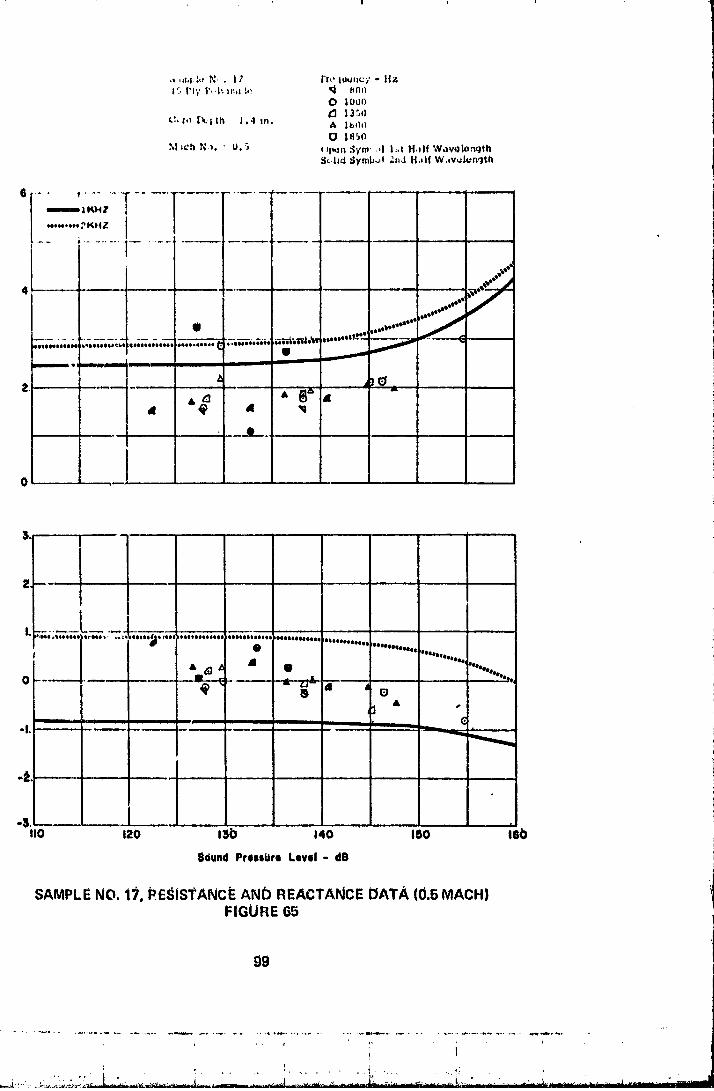
! I
•_-_._.:. N, . 17 Fz',,lu,J.c_' - liz1_.I'1'/ P.,I;_I:_l.!,._ _ _N_I
0 looo
L:,r. l_..;th i.4 m. _ l¢_*h_Q IA_o
M lch _'_,_._ U. '_ ( q_n _'m .d l:_t H,llf W,w_longth$_.hd _ymb_l 2s_dH.,I(W.voh..ngth
........T,.......1.........._K,,zI /
Y
m,=mm. • 1
,, i.,@ ....
I
m_J .,
• iI
0 "**********,
& _¢1_ i " .... ' ,,,,....... ..........
_-- ill
&
i i i _
llo 12o i_b i4o iSo leo
$¢iund Presslire Level - dB
SAMPLE NO, 17. _E_ISTANcIE AND REACTANCE DATA (0.5 MACH)FIGURE 65
O9
00000002
Copyright © 2022 FDOKUMEN