Add–drop filter based on apodized surface-corrugated gratings
7
Add – drop filter based on apodized surface-corrugated gratings Dorothea Wiesmann, Roland Germann, and Gian-Luca Bona IBM Research, Zurich Research Laboratory, CH-8803 Ru ¨ schlikon, Switzerland Christian David Laboratory for Micro- and Nanotechnology, Paul Scherrer Institute, CH-5232 Villigen-PSI, Switzerland Daniel Erni and Heinz Ja ¨ ckel Department of Information Technology and Electrical Engineering, Swiss Federal Institute of Technology (ETH) Zurich, CH-8092 Zurich, Switzerland Received June 26, 2002; revised manuscript received September 17, 2002 We report on the fabrication of a grating-based add– drop filter in SiON planar waveguide technology. We achieved apodization of the Bragg grating by concatenating subgratings with various duty cycles. We present the theoretical and experimental dependence of the coupling coefficient on the duty cycle, which leads to a minimum coupling coefficient of 30%. With a breeder genetic algorithm we were able to find optimal apodiza- tion profiles within this limited coupling coefficient range. The final device is compatible with a 100-GHz channel spacing and has a bandwidth utilization factor of 36%. © 2003 Optical Society of America OCIS codes: 050.0050, 050.2770, 060.4230, 130.0130, 130.3120, 230.1480, 230.7390. 1. INTRODUCTION The migration of wavelength division multiplexing schemes from point-to-point long-haul systems to meshed metropolitan area networks demands optical filters that add and/or drop single-wavelength channels at certain network nodes while allowing the majority of the chan- nels to pass the node undisturbed. One possible design of such an add – drop filter consists of a balanced Mach– Zehnder interferometer with two identical Bragg grat- ings, one on each of the two interferometer arms. This was originally suggested by Johnson et al. 1 and is sche- matically shown in Fig. 1. This filter is favorable over other designs 2,3 when small channel distances and inte- gration with other planar optical waveguide components are desired and outweighs the disadvantage of a limited tunability when the filter is implemented in glass waveguides. As described by Johnson et al., 1 the wave- length characteristic in a perfect filter implementation is determined solely by the Bragg grating. More specifi- cally the spectrum at the drop port corresponds to the re- flection spectrum of the grating and the spectrum at the through port of the grating’s transmission spectrum. Therefore, to ensure a low interchannel cross talk, one must suppress the sidelobes in the reflection spectrum of a uniform Bragg grating by tapering the grating strength. 4 In semiconductors or planar glass waveguides, Bragg gratings can be realized by etching a corrugation into a waveguide surface. For variation of the coupling strength the following schemes have been proposed: • A variation in the etch depth is the obvious way to ad- just the coupling strength to achieve a certain apodization profile. 5 However, in view of process reproducibility, the use of a binary etching process is preferred. • One way to change the effective strength of a grating is to insert grating-free waveguide sections. Shibata et al. 6 alternate these sections with an increased propor- tion of corrugated waveguide length in the middle of the grating assembly. It is, however, neither straightforward to find the optimal distribution of corrugated and grating- free sections, nor is the maximum achievable sidelobe suppression easy to calculate. Shibata et al. 6 demon- strated a 210-dB suppression; our own simulations and optimizations give best simulated results of 220 dB. • Two other apodization schemes for corrugated grat- ings use another basic principle, namely, detuning of the constructive interference between resonant waves re- flected at the various refractive-index steps. This can be achieved by a change in the optical path lengths either within one period or for two consecutive periods. The former method thus tunes the duty cycle away from 50% to decrease the grating strength and was suggested by Sakata. 7 The duty cycle is defined as the ratio of grating- tooth width w and grating period L. For duty cycles smaller than 50%, that grating tooth is narrower than the grating groove. The second method proposed by Lupu et al. 8 alternates one period, having a much smaller pe- riod length, with one having an equivalently larger grat- ing period. At first glance both methods seem equally difficult if the production of small grating grooves (tens of nanometers) and small grating ridges is equally demand- ing. We found, 9 however, that small grating ridges are feasible, whereas narrow grooves are not completely filled Wiesmann et al. Vol. 20, No. 3/March 2003/J. Opt. Soc. Am. B 417 0740-3224/2003/030417-07$15.00 © 2003 Optical Society of America
Transcript of Add–drop filter based on apodized surface-corrugated gratings

Wiesmann et al. Vol. 20, No. 3 /March 2003/J. Opt. Soc. Am. B 417
Add–drop filter based on apodizedsurface-corrugated gratings
Dorothea Wiesmann, Roland Germann, and Gian-Luca Bona
IBM Research, Zurich Research Laboratory, CH-8803 Ruschlikon, Switzerland
Christian David
Laboratory for Micro- and Nanotechnology, Paul Scherrer Institute, CH-5232 Villigen-PSI, Switzerland
Daniel Erni and Heinz Jackel
Department of Information Technology and Electrical Engineering, Swiss Federal Institute of Technology (ETH)Zurich, CH-8092 Zurich, Switzerland
Received June 26, 2002; revised manuscript received September 17, 2002
We report on the fabrication of a grating-based add–drop filter in SiON planar waveguide technology. Weachieved apodization of the Bragg grating by concatenating subgratings with various duty cycles. We presentthe theoretical and experimental dependence of the coupling coefficient on the duty cycle, which leads to aminimum coupling coefficient of 30%. With a breeder genetic algorithm we were able to find optimal apodiza-tion profiles within this limited coupling coefficient range. The final device is compatible with a 100-GHzchannel spacing and has a bandwidth utilization factor of 36%. © 2003 Optical Society of America
OCIS codes: 050.0050, 050.2770, 060.4230, 130.0130, 130.3120, 230.1480, 230.7390.
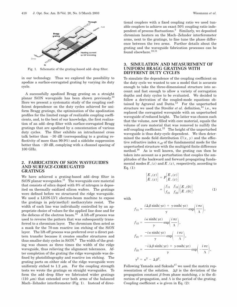
1. INTRODUCTIONThe migration of wavelength division multiplexingschemes from point-to-point long-haul systems to meshedmetropolitan area networks demands optical filters thatadd and/or drop single-wavelength channels at certainnetwork nodes while allowing the majority of the chan-nels to pass the node undisturbed. One possible designof such an add–drop filter consists of a balanced Mach–Zehnder interferometer with two identical Bragg grat-ings, one on each of the two interferometer arms. Thiswas originally suggested by Johnson et al.1 and is sche-matically shown in Fig. 1. This filter is favorable overother designs2,3 when small channel distances and inte-gration with other planar optical waveguide componentsare desired and outweighs the disadvantage of a limitedtunability when the filter is implemented in glasswaveguides. As described by Johnson et al.,1 the wave-length characteristic in a perfect filter implementation isdetermined solely by the Bragg grating. More specifi-cally the spectrum at the drop port corresponds to the re-flection spectrum of the grating and the spectrum at thethrough port of the grating’s transmission spectrum.Therefore, to ensure a low interchannel cross talk, onemust suppress the sidelobes in the reflection spectrum ofa uniform Bragg grating by tapering the gratingstrength.4
In semiconductors or planar glass waveguides, Bragggratings can be realized by etching a corrugation into awaveguide surface. For variation of the couplingstrength the following schemes have been proposed:
• A variation in the etch depth is the obvious way to ad-
0740-3224/2003/030417-07$15.00 ©
just the coupling strength to achieve a certain apodizationprofile.5 However, in view of process reproducibility, theuse of a binary etching process is preferred.
• One way to change the effective strength of a gratingis to insert grating-free waveguide sections. Shibataet al.6 alternate these sections with an increased propor-tion of corrugated waveguide length in the middle of thegrating assembly. It is, however, neither straightforwardto find the optimal distribution of corrugated and grating-free sections, nor is the maximum achievable sidelobesuppression easy to calculate. Shibata et al.6 demon-strated a 210-dB suppression; our own simulations andoptimizations give best simulated results of 220 dB.
• Two other apodization schemes for corrugated grat-ings use another basic principle, namely, detuning of theconstructive interference between resonant waves re-flected at the various refractive-index steps. This can beachieved by a change in the optical path lengths eitherwithin one period or for two consecutive periods. Theformer method thus tunes the duty cycle away from 50%to decrease the grating strength and was suggested bySakata.7 The duty cycle is defined as the ratio of grating-tooth width w and grating period L. For duty cyclessmaller than 50%, that grating tooth is narrower than thegrating groove. The second method proposed by Lupuet al.8 alternates one period, having a much smaller pe-riod length, with one having an equivalently larger grat-ing period. At first glance both methods seem equallydifficult if the production of small grating grooves (tens ofnanometers) and small grating ridges is equally demand-ing. We found,9 however, that small grating ridges arefeasible, whereas narrow grooves are not completely filled
2003 Optical Society of America
418 J. Opt. Soc. Am. B/Vol. 20, No. 3 /March 2003 Wiesmann et al.
in our technology. Thus we explored the possibility toapodize a surface-corrugated grating by varying its dutycycle.
A successfully apodized Bragg grating on a straightplanar SiON waveguide has been shown previously.10
Here we present a systematic study of the coupling coef-ficient dependence on the duty cycles achieved for uni-form Bragg gratings, the optimization of the apodizationprofiles for the limited range of realizable coupling coeffi-cients, and, to the best of our knowledge, the first realiza-tion of an add–drop filter with surface-corrugated Bragggratings that are apodized by a concatenation of variousduty cycles. The filter exhibits an intrachannel crosstalk better than 230 dB (corresponding to a grating re-flectivity of more than 99.9%) and a sidelobe suppressionbetter than 220 dB, complying with a channel spacing of100 GHz.
2. FABRICATION OF SiON WAVEGUIDESAND SURFACE-CORRUGATEDGRATINGSWe have achieved a grating-based add–drop filter inSiON planar waveguides.11 The waveguide core materialthat consists of silica doped with 8% of nitrogen is depos-ited on thermally oxidized silicon wafers. The gratingswere defined before we structured the ridge waveguide.We used a LION-LV1 electron-beam machine to exposethe gratings in poly(methyl) methacrylate resist. Thewidth of each line was individually controlled by an ap-propriate choice of values for the applied line dose and forthe defocus of the electron beam.12 A lift-off process wasused to reverse the pattern that was subsequently trans-ferred to a chromium layer. The chromium then acted asa mask for the 70-nm reactive ion etching of the SiONlayer. The lift-off process was preferred over a direct pat-tern transfer because it creates smaller structures andthus smaller duty cycles in SiON.9 The width of the grat-ing was chosen as three times the width of the ridgewaveguide, thus relieving the alignment tolerances. Af-ter completion of the grating the ridge waveguide was de-fined by photolithography and reactive ion etching. Thegrating parts on either side of the ridge waveguide wereuniformly etched to 1.2 mm. For the coupling strengthtests we wrote the gratings on straight waveguides. Toform the add–drop filter we fabricated wider gratings(110 mm) that extended over both arms of the balancedMach–Zehnder interferometer (Fig. 1). Instead of direc-
Fig. 1. Schematic of the grating-based add–drop filter.
tional couplers with a fixed coupling ratio we used tun-able couplers to achieve an exact 50% coupling ratio inde-pendent of process fluctuations.3 Similarly, we depositedchromium heaters on the Mach–Zehnder interferometerarms, next to the gratings, to fine tune the phase differ-ence between the two arms. Further details about thegrating and the waveguide fabrication processes can befound elsewhere.10,11
3. SIMULATION AND MEASUREMENT OFUNIFORM BRAGG GRATINGS WITHDIFFERENT DUTY CYCLESTo simulate the dependence of the coupling coefficient onthe duty cycle we wanted to use a model that is accurateenough to take the three-dimensional structure into ac-count and fast enough to allow a variety of corrugationdepths and duty cycles to be evaluated. We decided tofollow a derivation of the coupled-mode equations ob-tained by Agrawal and Dutta.13 For the unperturbedstructure we used the Streifer et al. definition,14 i.e., wereplaced the corrugated waveguide with an unperturbedwaveguide of reduced height. The latter was chosen suchthat the volume, now filled with core material, equals thevolume of core material that was removed to nullify theself-coupling coefficient.15 The height of the unperturbedwaveguide is thus duty-cycle dependent. We then deter-mined the mode field distribution U(x, y) and the effec-tive refractive index neff of the fundamental mode for theunperturbed structure with the multigrid finite differencemethod.16 As is well known, the grating can then betaken into account as a perturbation that couples the am-plitudes of the backward and forward propagating funda-mental modes E1(z) and E2(z), respectively, according toEq. (1):
FE1~z !
E2~z !G 5 FFE1~z !
E2~z !G5 S f11 f12
f21 f22D FE1~0 !
E2~0 !G , (1)
with
f11 5iDb sinh~gz ! 1 g cosh~gz !
gexpS ipz
LD ,
f12 5ik sinh~gz !
gexpS ipz
LD ,
f21 52ik sinh~gz !
gexpS 2
ipz
LD ,
f22 52iDb sinh~gz ! 1 g cosh~gz !
gexpS 2
ipz
LD ,
g2 5 k2 2 Db2.
Following Yamada and Sakuda17 we used the matrix rep-resentation of the solution. Db is the deviation of thepropagation constant b from phase matching, z is the di-rection of propagation, and L is the period of the grating.Coupling coefficient k is given in Eq. (2):

Wiesmann et al. Vol. 20, No. 3 /March 2003/J. Opt. Soc. Am. B 419
k 5b
2neff
EE De1~x, y !U2~x, y !dxdy
EE U2~x, y !dxdy
, (2)
where De1 is the first Fourier coefficient of the dielectricperturbation. Note that we have arranged the dielectricperturbation symmetrically around z 5 0 to obtain a realvalue18 for k. Inserting the Fourier coefficient for rectan-gular grating teeth and a grating duty cycle of w/L leadsto
k 5ncore
2 2 ncladding2
nefflsinS p
w
LD
3
EEcorrugation
U2~x, y !dxdy
EE U2~x, y !dxdy
. (3)
Equation (3) reveals all the influences of the gratingduty cycle on the grating response.
• As mentioned above, the height of the unperturbedwaveguide depends on both the corrugation depth and theduty cycle. Because of the dependence of the unper-turbed waveguide geometry on the duty cycle, both the ef-fective refractive index neff and the mode profile U(x, y)depend on the duty cycle.
• The change in the mode profile U(x, y) results in aduty-cycle dependent overlap integral in Eq. (3). Themagnitude of the overlap integral and hence of k over thefull range of duty cycles changes by approximately 10%.
• The effective refractive index neff changes by approxi-mately 0.1% when the duty cycle is swept from 1 to 0.This effect on k is therefore negligible. On the otherhand, an neff change causes a duty-cycle dependent Braggresonance wavelength lBragg 5 2neffL. A 0.1% changemeans that the Bragg resonance wavelength varies up to1.5 nm along a grating that consists of different duty-cycle subgratings. This chirp results in an unwantedbroadening of the filter function. We compensated forthis by changing the period L of the gratings such thatlBragg is identical for all duty cycles.
• The major influence of the duty cycle on the couplingcoefficient is exerted by the term sin(pw/L) in Eq. (3),which states that the coupling coefficient can be tunedfrom 0 to its maximum value by a change in duty cyclefrom 0 to approximately 0.5 or from 1 to approximately0.5. Owing to the other effects mentioned above, themaximum coupling coefficient is achieved for duty cyclesslightly smaller than 0.5. An apodization of the gratingis hence possible through a concatenation of subgratingswith different duty cycles. The range of feasible dutycycles determines the possible degree of apodization.
Figure 2 shows the theoretical duty-cycle dependence ofthe coupling coefficient. The calculation was performedfor a standard SiON ridge waveguide.11 The grating-tooth height amounted to h 5 70 nm and the grating pe-riod to lBragg 5 1550 nm.
To assess the duty-cycle dependence of the coupling co-efficients predicted by the calculations, we fabricated a se-ries of uniform gratings on straight waveguides with vari-ous duty cycles. The lengths of the gratings were chosento result in a Bragg-resonant transmission loss between210 and 215 dB based on the theoretically determinedcoupling coefficients. The lengths lay between 0.2 and0.7 mm. Figure 3 shows the reflection and transmissionspectra of these gratings. The displayed measurementswere performed with TE-polarized light from a broadbandsource and an optical spectrum analyzer. The wave-length resolution of the latter explains the limited resolu-tion of the sidelobes in the reflection spectra, especially inthe weaker gratings with the smaller coupling coeffi-cients. For better visibility we offset the transmissionspectra by 7.5 dB and the reflection spectra by 14 dB. Inaddition, we enlarged the transmission spectra for thetwo weakest gratings by factors of 10 and 20, respectively.As can be seen from the intensity distribution of the side-lobes, the optical quality of the gratings with duty cyclesbetween 20% and 50% is good. The Bragg resonancewavelength is also identical for these gratings, indicatingthat the different effective refractive indices have been
Fig. 2. Dependence of the calculated coupling coefficient on theduty cycle for TE-polarized light (open circles) and TM-polarizedlight (filled squares).
Fig. 3. Transmission (left) and reflection (right) spectra for a setof uniform gratings with different duty cycles with lengths be-tween 0.2 and 0.7 mm. The spectra were measured with TE-polarized light. For better visibility both spectra have been off-set and the transmission spectra for the two smallest duty-cyclegratings have been enlarged by factors of 10 and 20.

420 J. Opt. Soc. Am. B/Vol. 20, No. 3 /March 2003 Wiesmann et al.
successfully compensated by an appropriate choice of thegrating period. Below a duty cycle of 15% the sidelobe in-tensity distribution starts to deviate from expected sync-like functions and the Bragg resonance wavelength isshifted toward longer wavelengths. The former result in-dicates a coupling coefficient fluctuation along the grat-ing, the latter that the effective refractive index deviatesfrom the expected value for which the grating period waschosen.
From the magnitude of the transmission loss at theBragg resonance we have determined the coupling coeffi-cient k according to
Rresonance 5 1 2 Tresonance 5 tanh2~kL !, (4)
which can be derived from Eq. (1). Figure 4 shows thecalculated and experimental coupling coefficients as afunction of the duty cycle. The discrepancy between the
Fig. 4. Simulated (open circles) and experimentally determined(filled squares) coupling coefficients as functions of the gratingduty cycle. The measured values are for TE-polarized light.The experimentally determined coupling coefficients for TM-polarized light are identical within the measurement accuracy.The simulation uses grating-teeth dimensions determined from across section of a test wafer measured in a secondary electron mi-croscope. Perfectly rectangular grating teeth both on and besidethe grating ridge are assumed.
Fig. 5. Simulated (open circles) and experimentally determined(filled squares) coupling coefficients as functions of the gratingduty cycle. Degradation of the grating teeth beside the gratingridge was taken into account for the simulation.
simulation and the experimental results can be dividedinto a difference in magnitude of the coupling and differ-ent shapes of the coupling coefficient dependence on theduty cycle. First, for a duty cycle of approximately 50%the grating seems to couple stronger than predicted bythe simulations. We explain this as the result of a slightdeviation in the etch depth. With an improved processcontrol this can be avoided. More striking are the differ-ent shapes, i.e., the much more rapid decrease in the cou-pling strength when we use smaller duty cycles. In partthis is caused by a degradation of the grating teeth duringthe waveguide ridge structuring. As mentioned aboveand as described in more detail in Ref. 9, the grating isstructured prior to the etching of the ridge waveguide,therefore the grating teeth beside the grating ridge un-dergo a 1.2-mm anisotropic uniform reactive ion etching.During this step of the process the tooth shape changesfrom almost rectangular to triangular and the height in-creasingly decreases the narrower the grating teeth, i.e.,the smaller the duty cycle. Since approximately 30% ofthe coupling occurs at the grating teeth beside the gratingridge in the case of no degradation, the overall couplingcan thus be decreased at most by the amount for smallduty cycles. Because the effect is less pronounced forlarger features, the dependence of the coupling coefficienton the duty cycle becomes steeper. Figure 5 shows an-other comparison between the experimentally determinedcoupling coefficient and the simulated values of anotherwafer, where the simulation takes the degradation of thegrating teeth into account.
The uneven sidelobe intensities in the reflection spec-tra and the vanishing coupling strength for gratings withsmaller duty cycles indicate, however, that not only thegrating teeth beside the grating ridge are degraded butalso the ones on the grating ridge. Although the statis-tical grating-tooth failure opens up the whole range ofcoupling coefficients, from its maximum to zero, theseranges of small duty cycles should be avoided for the sakeof a reproducible process. For the construction ofapodized gratings the range of duty cycles lies between20% and 50% and thus coupling coefficients of between30% and the maximum value can therefore be used.
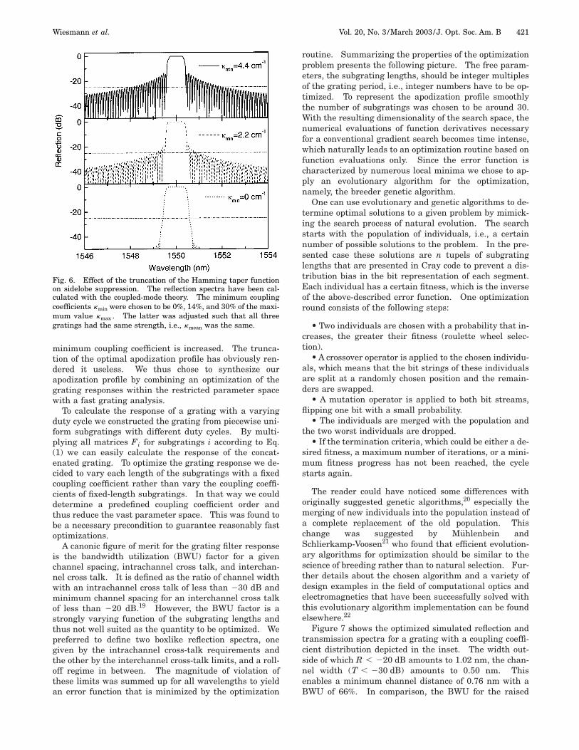
4. OPTIMIZATION OF THE APODIZATIONPROFILEAll analytical methods for the synthesis of apodized grat-ings, i.e., all methods that can be used to calculate thenecessary coupling strength distribution given a desiredreflection spectrum of a Bragg grating, suffer from theirsolution domain, which is infinite. However, apodizedgratings constructed by a concatenation of gratings withdifferent duty cycles, not only require a finite gratinglength but also restrict the coupling coefficient range sig-nificantly. A truncation or raising of the found couplingstrengths distribution is necessary to map the synthe-sized solutions into realistic parameter space. Figure 6shows the effect of raising a Hamming taper function tocomply with minimum coupling coefficients of 0%, 14%,and 30%. Grating strength kL was set to seven for allthree gratings. As one can see from Fig. 6, the sidelobelevel increases from 246 to 219 and to 214 dB when the
Wiesmann et al. Vol. 20, No. 3 /March 2003/J. Opt. Soc. Am. B 421
minimum coupling coefficient is increased. The trunca-tion of the optimal apodization profile has obviously ren-dered it useless. We thus chose to synthesize ourapodization profile by combining an optimization of thegrating responses within the restricted parameter spacewith a fast grating analysis.
To calculate the response of a grating with a varyingduty cycle we constructed the grating from piecewise uni-form subgratings with different duty cycles. By multi-plying all matrices Fi for subgratings i according to Eq.(1) we can easily calculate the response of the concat-enated grating. To optimize the grating response we de-cided to vary each length of the subgratings with a fixedcoupling coefficient rather than vary the coupling coeffi-cients of fixed-length subgratings. In that way we coulddetermine a predefined coupling coefficient order andthus reduce the vast parameter space. This was found tobe a necessary precondition to guarantee reasonably fastoptimizations.
A canonic figure of merit for the grating filter responseis the bandwidth utilization (BWU) factor for a givenchannel spacing, intrachannel cross talk, and interchan-nel cross talk. It is defined as the ratio of channel widthwith an intrachannel cross talk of less than 230 dB andminimum channel spacing for an interchannel cross talkof less than 220 dB.19 However, the BWU factor is astrongly varying function of the subgrating lengths andthus not well suited as the quantity to be optimized. Wepreferred to define two boxlike reflection spectra, onegiven by the intrachannel cross-talk requirements andthe other by the interchannel cross-talk limits, and a roll-off regime in between. The magnitude of violation ofthese limits was summed up for all wavelengths to yieldan error function that is minimized by the optimization
Fig. 6. Effect of the truncation of the Hamming taper functionon sidelobe suppression. The reflection spectra have been cal-culated with the coupled-mode theory. The minimum couplingcoefficients kmin were chosen to be 0%, 14%, and 30% of the maxi-mum value kmax . The latter was adjusted such that all threegratings had the same strength, i.e., kmean was the same.
routine. Summarizing the properties of the optimizationproblem presents the following picture. The free param-eters, the subgrating lengths, should be integer multiplesof the grating period, i.e., integer numbers have to be op-timized. To represent the apodization profile smoothlythe number of subgratings was chosen to be around 30.With the resulting dimensionality of the search space, thenumerical evaluations of function derivatives necessaryfor a conventional gradient search becomes time intense,which naturally leads to an optimization routine based onfunction evaluations only. Since the error function ischaracterized by numerous local minima we chose to ap-ply an evolutionary algorithm for the optimization,namely, the breeder genetic algorithm.
One can use evolutionary and genetic algorithms to de-termine optimal solutions to a given problem by mimick-ing the search process of natural evolution. The searchstarts with the population of individuals, i.e., a certainnumber of possible solutions to the problem. In the pre-sented case these solutions are n tupels of subgratinglengths that are presented in Cray code to prevent a dis-tribution bias in the bit representation of each segment.Each individual has a certain fitness, which is the inverseof the above-described error function. One optimizationround consists of the following steps:
• Two individuals are chosen with a probability that in-creases, the greater their fitness (roulette wheel selec-tion).
• A crossover operator is applied to the chosen individu-als, which means that the bit strings of these individualsare split at a randomly chosen position and the remain-ders are swapped.
• A mutation operator is applied to both bit streams,flipping one bit with a small probability.
• The individuals are merged with the population andthe two worst individuals are dropped.
• If the termination criteria, which could be either a de-sired fitness, a maximum number of iterations, or a mini-mum fitness progress has not been reached, the cyclestarts again.
The reader could have noticed some differences withoriginally suggested genetic algorithms,20 especially themerging of new individuals into the population instead ofa complete replacement of the old population. Thischange was suggested by Muhlenbein andSchlierkamp-Voosen21 who found that efficient evolution-ary algorithms for optimization should be similar to thescience of breeding rather than to natural selection. Fur-ther details about the chosen algorithm and a variety ofdesign examples in the field of computational optics andelectromagnetics that have been successfully solved withthis evolutionary algorithm implementation can be foundelsewhere.22
Figure 7 shows the optimized simulated reflection andtransmission spectra for a grating with a coupling coeffi-cient distribution depicted in the inset. The width out-side of which R , 220 dB amounts to 1.02 nm, the chan-nel width (T , 230 dB) amounts to 0.50 nm. Thisenables a minimum channel distance of 0.76 nm with aBWU of 66%. In comparison, the BWU for the raised

422 J. Opt. Soc. Am. B/Vol. 20, No. 3 /March 2003 Wiesmann et al.
Hamming distribution (Fig. 6) amounts to 37% and thatfor a uniform grating with the same average gratingstrength to 14%.
If we keep in mind Kogelnik’s intuitive motivation oftaper profiles, namely, that most importantly the couplingcoefficient is to vary smoothly, the found apodization pro-file is to be expected at least qualitatively. The unavoid-able jump from zero to 30% of kmax at the grating edges ismatched by a steep slope of the apodization profile at thegrating edges.
5. MEASUREMENT OF AN APODIZEDADD–DROP FILTERWe used the optimized coupling coefficient distribution tofabricate a Bragg grating-based add–drop filter (Fig. 1).The corresponding duty-cycle distribution was calculatedwith Eq. (3) and uses a minimum duty cycle of approxi-mately 10%. Figure 8 shows the spectra at the drop andthe through ports measured with TM-polarized light from
Fig. 7. Calculated reflection and transmission spectra of anapodized grating with a coupling strength distribution that wasoptimized with the breeder genetic algorithm. The couplingstrength distribution is shown in the inset.
Fig. 8. Comparison between measured and simulated transmis-sion and reflection spectra for apodized gratings, based on a con-catenation of gratings with different duty cycles. The measure-ment was performed with TM-polarized light.
a tunable fiber laser together with its simulated counter-parts. The simulation is based on the coupling coeffi-cients that were determined from the uniform gratings onthe same wafer (Fig. 4), which results in a slightly steepercoupling coefficient distribution at the grating ends thanwas found optimal. The agreement between experimen-tal and theoretical curves emphasizes the success of theapodization concept, namely, the concatenation of differ-ent duty-cycle gratings. It also shows that the simula-tion approach to dissect the grating into piecewise uni-form gratings is sufficiently accurate for our application.Although the apodization profile is not optimal, weachieved a channel bandwidth, i.e., the wavelength rangeover which the transmission is less than 230 dB, of ap-proximately 0.29 nm. The sidelobes in the reflectionspectrum are better suppressed than 220 dB outside aband of 1.26 nm, which allows a minimum channel spac-ing of 0.78 nm and thus complies with a 100-GHz channelspacing. The BWU factor was 36%.
Figure 9 shows the optical spectra measured at all fourports of the add–drop filter for TE-polarized light. Thedifferences between the transmission and the reflectionspectra of the Bragg gratings for the two interferometerarms result in an optical signal at the second output portand the input port. From the spectrum of the light re-flected back into the input port, in particular, we can seethat the height of the first sidelobes in the reflection spec-tra of the two gratings differs by as much as 50%. Weattribute this to the earlier described statistical failure ofsmall grating teeth that could be greatly reduced if we in-creased the minimum duty cycle from 10% to 20%.
6. SUMMARYIn summary, we have presented the successful realizationof a grating-based add–drop filter with an apodizationthrough concatenation of subgratings with different dutycycles. It has been shown that a duty-cycle variation be-tween 20% and 50% results in high-quality gratings thatallow a coupling coefficient variation from 30% to 100% ofthe maximum value. Based on this range of duty cycles,the mapping of conventional apodization functions fails.
Fig. 9. Spectra measured at the four ports of the add–drop filterwith TE-polarized light. The spectra were normalized to thetransmission through a noncorrugated waveguide.

Wiesmann et al. Vol. 20, No. 3 /March 2003/J. Opt. Soc. Am. B 423
We thus applied a breeder genetic algorithm that yieldsfar better apodization. Finally, the results have beencombined to fabricate an add–drop filter that is compat-ible with a 100-GHz channel spacing and has a band-width utilization factor of 36%.
D. Wiesmann’s e-mail address is [email protected].
REFERENCES1. D. C. Johnson, K. O. Hill, F. Bilodeau, and S. Faucher, ‘‘New
design concept for a narrowband wavelength-selective opti-cal tap and combiner,’’ Electron. Lett. 23, 668–669 (1987).
2. C. R. Giles and V. Mizrahi, ‘‘Low-loss add/drop multiplexersfor WDM lightwave networks,’’ in Technical Digest of TenthInternational Conference on Integrated Optics and OpticalFiber Communication (Chinese University Press, HongKong, 1995), paper ThC2-1, pp. 66–67.
3. B. J. Offrein, F. Horst, G. L. Bona, R. Germann, H. W. M.Salemink, and R. Beyeler, ‘‘Adaptive gain equalizer in high-index-contrast SiON technology,’’ IEEE Photon. Technol.Lett. 12, 504–506 (2000).
4. H. Kogelnik, ‘‘Filter response of nonuniform almost-periodicstructures,’’ Bell Syst. Tech. J. 55, 109–126 (1976).
5. A. Talneau, C. Ougier, and S. Slempkes, ‘‘Multiwavelengthgrating reflectors for widely tunable laser,’’ IEEE Photon.Technol. Lett. 8, 497–499 (1996).
6. Y. Shibata, T. Tamamura, S. Oku, and Y. Kondo, ‘‘Couplingcoefficient modulation of waveguide grating using sampledgrating,’’ IEEE Photon. Technol. Lett. 6, 1222–1224 (1994).
7. H. Sakata, ‘‘Sidelobe suppression in grating-assistedwavelength-selective couplers,’’ Opt. Lett. 17, 463–465(1992).
8. A. Lupu, A. Carenco, P. Win, H. Sik, P. Boulet, M. Carre,and S. Slempkes, ‘‘Spectral response apodization of Bragg-like optical filters,’’ in Optical Fiber Communication Confer-ence (OFC)/International Conference on Integrated Opticsand Optical Fiber Communications (IOOC), PostconferenceDigest (Optical Society of America, Washington, D.C.,1999), paper WM26-7, pp. 271–273.
9. C. David, D. Wiesmann, R. Germann, F. Horst, B. J. Of-frein, R. Beyeler, H. W. M. Salemink, and G. L. Bona,‘‘Apodized Bragg gratings in planar waveguides for add-drop filters,’’ Microelectron. Eng. 57/58, 713–719 (2001).
10. D. Wiesmann, C. David, R. Germann, D. Erni, and G. L.Bona, ‘‘Apodized surface-corrugated gratings with varyingduty cycles,’’ IEEE Photon. Technol. Lett. 12, 639–641(2000).
11. R. Germann, H. W. M. Salemink, R. Beyeler, G. L. Bona, F.Horst, I. Massarek, and B. J. Offrein, ‘‘Silicon oxynitridelayers for optical waveguide applications,’’ J. Electrochem.Soc. 147, 2237–2241 (2000).
12. C. David and D. Hambach, ‘‘Line width control using a de-focused low voltage electron beam,’’ Microelectron. Eng. 46,219–222 (1999).
13. G. P. Agrawal and N. K. Dutta, Long-Wavelength Semicon-ductor Lasers (Van Nostrand Reinhold, New York, 1986).
14. W. Streifer, D. R. Scifres, and R. D. Burnham, ‘‘Coupling co-efficient for distributed feedback single- and double-heterostructure diode lasers,’’ IEEE J. Quantum Electron.QE-11, 867–873 (1975).
15. Y. Yamamoto, T. Kamiya, and H. Yanai, ‘‘Improved coupledmode analysis of corrugated waveguides and lasers,’’ IEEEJ. Quantum Electron. QE-14, 245–258 (1978).
16. P. Lusse, P. Stuwe, J. Schule, and H.-G. Unger, ‘‘Analysis ofvectorial mode fields in optical waveguides by a new finitedifference method,’’ J. Lightwave Technol. 12, 487–493(1994).
17. M. Yamada and K. Sakuda, ‘‘Analysis of almost-periodic dis-tributed feedback slab waveguides via a fundamental ma-trix approach,’’ Appl. Opt. 26, 3474–3478 (1987).
18. N. Matuschek, F. X. Kartner, and U. Keller, ‘‘Exact coupled-mode theories for multilayer interference coatings with ar-bitrary strong index modulations,’’ IEEE J. Quantum Elec-tron. 33, 295–302 (1987).
19. T. Strasser, P. Chandonnet, J. DeMarco, C. Soccolich, J. Pe-drazzani, D. DiGiovanni, M. Andrejco, and D. Shenk, ‘‘AUV-induced fiber grating OADM devices for efficient bandwidthutilization,’’ in Optical Fiber Communication Conference,Vol. 2 of 1996 OSA Technical Digest Series (Optical Societyof America, Washington, D.C., 1996), pp. 360–363.
20. J. H. Holland, Adaptation in Natural and Artificial Systems(University of Michigan, Ann Arbor, Mich., 1975).
21. H. Muhlenbein and D. Schlierkamp-Voosen, ‘‘The science ofbreeding and its application to the breeder genetic algo-rithm BGA,’’ Evol. Comput. 1, 335–360 (1993).
22. D. Erni, D. Wiesmann, M. Spuhler, S. Hunziker, E. Moreno,B. Oswald, J. Frohlich, and Ch. Hafner, ‘‘Applications ofevolutionary optimization algorithms in computational op-tics,’’ Appl. Comput. Electromagn. Soc. J. 15, 43–60 (2000).