How to build safe roofs with corrugated galvanized iron (CGI ...
238
How to build safe roofs with corrugated galvanized iron (CGI) sheeting Shelter Research Unit Innovating shelter ifrc-sru.org
-
Upload
khangminh22 -
Category
Documents
-
view
3 -
download
0
Transcript of How to build safe roofs with corrugated galvanized iron (CGI ...
How to build safe roofs with corrugated galvanized iron (CGI) sheeting
Shelter Research UnitInnovating shelter
ifrc-sru.org
How to build Safe RoofS witH CoRRugated galvanized iRon (Cgi) SHeeting
Important notIcethe information provided in this manual and the calculations are based on up to date material specifications, field testing and current practice of calculating structures (using Eurocodes 1, 3 and 5) and must be treated as guidelines only and evaluated for suitability in the context of specific local conditions. Risk is inherent in construc-tion and especially after natural disaster caution must be exercised so as not to increase the threat to disaster affected persons. Users of this manual do so solely at their own risk.
the international federation of the Red Cross and Red Crescent societies – Shelter Research Unit (IFRC-SRU) nor any of it’s employees or technical consultants assume any liability for damages, loss or claims, of any nature, including the death or injury of persons or property damage, associated with the use of or reliance upon information contained in this manual.

This publication has been made possible through the generous support of:
Belgian Red Cross, Flemish and French speaking communities:
Contents
Acknowledgements 11 Foreword 13
about this manual 14 Structure of the manual 15 For whom is this manual? 16 technical terms used in this manual 17 Glossary of Terms (Alphabetical) 23 Acronyms 26
section A Materials 29 A.1 Corrugated Roofing Materials 29 A.2 Corrugated Galvanized Iron or Steel (CGI) sheets 32 A.2.1. Dimensions and measurement for CGI sheets 33 A.2.2. Type of Galvanization or Coating 36 Advantages and disadvantages of each type of coating: 38 A.2.3 Coating thickness and service life for CGI sheets 39 A.2.4. Example Technical specifications for CGI sheets 48 A.2.5. Problems with CGI sheets and preventive measures 50 Corrosion 50 Measures to avoid corrosion problems: 52 Mechanical and physical deteriorations: 52 Fixings / fasteners failure: 53 A.3 Materials for the structural support of CGI roofs 54 A.3.1. Lumber / Timber 55 A.3.2. Coconut wood (coco lumber) 62 A.3.3. Bamboo 67 A.3.4. Metal 68 A.3.5. Advantages and disadvantages of each type of support 69 A.4 Fixings / fasteners and accessories 71 A.4.1. Roofing nails 72 Example technical specifications of roofing nails for CGI sheets 74 A.4.2. Roofing screws 75 A.4.3. Particular fixings for Metal and Bamboo 79 A.4.4. Sealing washers 81 A.5 Performance testing of fixings and supports conducted by IFRC-SRU 84 Comparative overview of roofing nails and roofing screws based on evidence from IFRC – SRU testing 89 A.6 Hurricane straps / ties 91 A.6.1. Coiled strap 92
table of contents

7
Contents
A 6.2. Hurricane straps to connect laths/battens to rafters 94 A.6.3. Hurricane straps to connect rafters to wall plates 96 A.6.4. Fasteners for hurricane straps and coiled straps 99 A.7 Roofing accessories: ridge capping and fascia capping 101 A.7.1. Ridge cap and hip cap 101 Example Technical specifications: Ridge cap (extract from the Emergency Items Catalogue) 103 A.7.2. Fascia / verge cap or bargeboard flashing 104 Practical Summary Section A 106 CGI sheets and accessories 106 Supports for CGI sheets: lumber / timber, coconut lumber, bamboo and metal: 111
section B Quality control, transportation and storage, basic safety equipment 112 B.1 Basic safety equipment 112 B.2 Quality control of the CGI sheet and other galvanized items 114 B.2.1. Tests to verify the dimensions of the CGI sheet 115 B.2.2. Tests to verify the thickness of the zinc coating 117 B.2.3. Tests to verify the quality of the zinc coating 124 B.3 Transportation and storage 126 B.3.1. CGI sheets and other galvanized roof covering items 126 B.3.2. Lumber / timber, coconut wood and bamboo 129 Practical Summary Section B 131
section c Roof shape and pitch 132 C.1 Effects of wind and earthquakes on structures 132 C.1.1. General effects of strong winds and earthquakes on structures 132 C.1.2. Effects of wind on structures 134 C.2 Wind pressure on walls for different shelter configurations 136 C.2.1. Wind pressure on walls 136 C.2.2. “Closed” shelter 137 C.2.3. “Open” shelter 138 C.2.4. Shelter elevated from the ground 139 C.3 Impact of wind pressure on different types of roofs 140 C.3.1. Cyclone categories and sustained wind speed 141 C.3.2. Exposure or Type of Terrain 143 C.3.3. Best orientation of shelter and roof 145 C.3.4. Advantages and disadvantages of the different roof shapes 146 C.3.5. Pitch of the roof 148 C.3.6 Roof Details 150 C.4 Choice of roof shape and pitch depending on the exposure (type of terrain) and wind speed 157 C.4.1. Urban area 159 C.4.2. Suburban and rural areas with cover of vegetation 162

8
Contents
C.4.3. Rural area with low vegetation 166 C.4.4. Coastal area 170 Practical Summary Section C 174
section D Installation guidelines 178 D.1 Useful tools to cover the roof with CGI sheets 179 D.2 CGI sheet layout 180 D.2.1. Layout of full-length CGI sheets per slope 180 D.2.2. Layout of more than one CGI sheet per slope 182 D.2.3. Overlaps and overhang 184 D.3 Fixings / fasteners 188 D.4 Installation details 191 D.4.1. Laths / battens / purlins 191 D.4.2. Eaves’ overhang 193 D.4.3. Edges / verges 196 D.4.4. Ridge caps 200 D.4.5. Hip details (hipped roofs) 203 D.4.6. Roof end for single-pitch roofs 204 D.5 Comparison of exemplary case study calculations 205 D.5.1. Suburban or rural area with cover of vegetation 207 D.5.2. Rural area with low vegetation 212 D.5.3. Coastal area 215 Practical Summary Section D 218
section e Roof maintenance and mitigation measures 220 E.1 Roof maintenance 221 E.1.1. Laths / battens and other structural elements 221 E.1.2. CGI sheets 221 E.1.3. Fixings of the CGI sheets 223 E.1.4. Hurricane straps / ties and their fixings 225 E.1.5. Check the gutters 225 E.2 Mitigation measures 226 E.2.1. Shelter with outside walls that are not airtight 226 E.2.2. Shelter with airtight walls: 227 E.2.3. Reinforcement measures to hold the roof covering in place 229 E.2.4 Types of anchors 237 Practical Summary Section E 240

9
Contents
AnneX (You will find the Annexes online under the provided links)Annex 1 – Galvanized steel sheet conversion table.pdf http://ifrc-sru.org/annex_1/Annex 2 – Conversion tables for roofing nails and screws.pdf http://ifrc-sru.org/annex_2/Annex 3 – defining Cyclone categories according to sustained wind speed.pdf http://ifrc-sru.org/annex_3/Annex 4 – Basic wind speed in various countries.pdf http://ifrc-sru.org/annex_4/Annex 5 – Explanations for the Roof Estimate Form.pdf http://ifrc-sru.org/annex_5/Annex 6 – Basic pitch of the roof in degree, percentage and dimensions http://ifrc-sru.org/annex_6/Annex 7 – Roof Estimate Form 2017.02.15 http://ifrc-sru.org/annex_7/Annex 8 – Library & further reading http://ifrc-sru.org/annex_8/

11
acknowledgements
Project coordination and editing of manual: Cecilia Braedt (IFRC-SRU)
Lead author: Emeline Decoray (Shelter over^head)
Laboratory and field tests by: Daniel Ledesma (IFRC-SRU)
Graphic design by: Teresa Boese (titrobonbon.de)
Photos: Emeline Decoray (Shelter over^head) and IFRC-SRU
Cover Photo: Emeline Decoray (Shelter over^head) and St vincent and the grenadines Red Cross
Special thanks to ICRC delegation Philippines particularly the Samar delegation for providing operational support and making their warehouse grounds in Samar avail-able for the field testing. Special thanks to Gafur M Nur Abdul, Britt Christiaens and Marco Alberti. Furthermore IFRC delegation Philippines, Wardell Eastwood, and the IFRC and Philippines Red Cross in Tacloban for facilitation and operational support.Ing. Jean Lamesch for sharing his extensive expert knowledge on CGI sheet and zinc coating.
Additional thanks to Alexander van Leersum (Netherlands RC), Azmat Ulla (IFRC), Charles Aurouet (French RC), Corinne Tréherne (IFRC), David Dalgado (IFRC), Ela Serdaroglu (IFRC), Leeanne Marshall (IFRC / Australian RC), Nadine Weber (Swiss Red Cross), Patrick Elliot (IFRC / British RC) Santiago de Luengo (IFRC / Mexican Red Cross), and Wardell Eastwood (IFRC) for peer review and valuable feedback and David Dalgado (IFRC) for final proof reading.

13
The World Disaster Report 20161 statistics of the last 10 years show that storms rank second, after earthquakes, in causing loss of lives and damage to property. Storms are also the natural disaster that, after floods, affects the highest number of people worldwide.
Pictures of the devastation after Typhoons, Cyclones or Hurricanes tell a clear story about the effects of such extreme weather events. Roofs torn off or huts and houses even completely overturned or destroyed by the impact of the winds.
Of course this destruction affects mostly the poorly built structures that are con-structed without much technical expertise or with low quality construction materials. However, low-cost construction does not have to result in poor performance. Most local building cultures in contexts that have been confronted with natural disasters like storms as long as anyone can remember, have developed techniques to build structures that resist the common disasters, using locally available, often natural materials. However, traditional techniques can usually not be applied to the new industrial materials that are used widely nowadays all over the world. In the last decade, Corrugated Galvanized Iron or Steel (CGI) sheeting has become the most commonly used roofing material worldwide and is also used widely in humanitarian shelter responses.
Given that to “build back safer” is the principle objective of humanitarian shelter and reconstruction interventions, the necessary expertise and knowledge for the construction of safe, cyclone resistant roofs with CGI sheeting. Especially, as the choice of material and little technical details can make a big difference for the overall performance of the roof and can have considerable effect on unit cost. In large scale operations also wider implications on local markets and livelihoods need to be con-sidered. Therefore, technical specifications of CGI sheeting and related fixings and installation techniques have repeatedly been topics of, heated discussions and disa-greement in Technical Working Groups (TWiGs) in Shelter Clusters at country level.
This booklet is an attempt to consolidate solid technical information on CGI sheeting and best practices of using it for cyclone resistant roofing in a comprehensible and accessible manner with the overall objective to contribute to reducing shelter related vulnerabilities that put the inhabitants’ lives at risks.
1 World Disaster Report 2016: Resilience: saving lives today, investing for tomorrow; International Federation of Red Cross and Red Crescent Societies, ISBN: 978-92-9139-240-7
foreword

14
about this manual
Corrugated Galvanized Iron or Steel (CGI or CGS) sheets are at present the best known, most widely available low cost roof covering material. There is an enor-mous variety of qualities of CGI sheets on the market, greatly varying in the different regions of the world.
This manual aims to give guidance how to chose the most suitable quality of CGI sheets for a given context and how to correctly handle and install CGI sheets as roof covering. Furthermore the manual presents some maintenance and preventive measures that help to ensure safety and durability of a CGI roof.
As this manual particularly focuses on improving safety and storm/cyclone resist-ance of roofs covered with CGI it provides some guidance on the most suitable roof-form and pitch to withstand expected wind loads, in order to help make informed choices for a given context. In areas with very low risk of strong winds the focus on high quality of CGI and strong fixings can be reduced.
PleAse note:This manual is not a manual on roof structures. Although it does give relevant rec-ommendations on shapes and pitches as well as on the spacing of laths and battens that are used as supports for the Cgi sheets as well as on hurricane straps to tie together the roof structure, it does not cover all essential constructive components, like joints and bracings that are critical for the stability of the roof structure, to the necessary detail.also snow loads have not been considered in the calculations as the need was not apparent. If need is confirmed an additional chapter on snow loads can be consid-ered.
The information and recommendations provided in this manual are based on:
● Engineering calculations for hipped, gable, gambrel and single-pitch roofs each with three different pitches and in four different wind-load-scenarios, according to Eurocode norms.
● Field testing of different qualities of CGI sheeting, fixings and supports conduct-ed in the Philippines.
● Desk-top review of material specs and other relevant information.
about thIs manual
15
about this manual
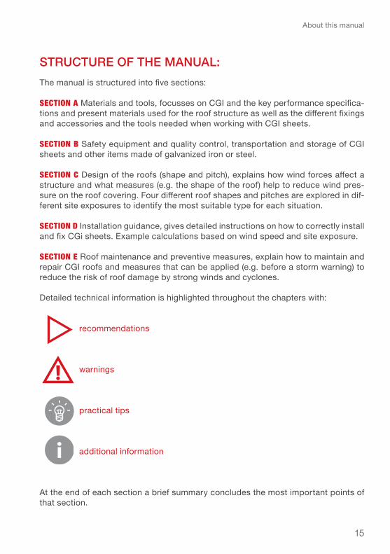
Structure of the mAnuAl:The manual is structured into five sections:
section A Materials and tools, focusses on CGI and the key performance specifica-tions and present materials used for the roof structure as well as the different fixings and accessories and the tools needed when working with CGI sheets.
section B Safety equipment and quality control, transportation and storage of CGI sheets and other items made of galvanized iron or steel.
section c Design of the roofs (shape and pitch), explains how wind forces affect a structure and what measures (e.g. the shape of the roof) help to reduce wind pres-sure on the roof covering. Four different roof shapes and pitches are explored in dif-ferent site exposures to identify the most suitable type for each situation.
section D Installation guidance, gives detailed instructions on how to correctly install and fix CGi sheets. Example calculations based on wind speed and site exposure.
section e Roof maintenance and preventive measures, explain how to maintain and repair CGI roofs and measures that can be applied (e.g. before a storm warning) to reduce the risk of roof damage by strong winds and cyclones.
Detailed technical information is highlighted throughout the chapters with:
recommendations
warnings
practical tips
additional information
At the end of each section a brief summary concludes the most important points of that section.

16
about this manual
Additional technical information is presented in the Annexes:
● conversion table for galvanized steel sheet, ● conversion table for roofing nails and screws, ● categories of cyclones and sustained wind speeds, ● table of basic wind speed in various countries, ● guidance on how to use the Roof Estimate Form, ● basic pitch of the roof (in degrees, percentage and dimensions), ● library and further readings.
In Annex 5 you will find Explanations for the Roof Estimate Form (Excel spreadsheet, Annex 7) with instructions for use. The Roof Estimate Form is a calculation form specific for shelters (maximum size: 5.4 x 7.2 m, maximum height: 5 m) based on the Eurocode (European standards).
It is meant to help check whether the design of the shelter is adapted to the environ-mental conditions (site exposure and wind speed) and determine the quantities of materials needed to cover the roof.
for whom iS thiS mAnuAl?
The manual should serve several target groups and accordingly provides different levels of technical information and detail:
For decision makers to get a general understanding of issues to be considered in the programming, planning and cost-calculation of a shelter project
for practitioners involved in implementing shelter projects. Architects and engineers as well as logisticians will find detailed technical information and practical recom-mendations to support their work.
Beneficiaries and self-builders will find comprehensible guidance to help them to build a safer roof for their shelter and to maintain it in good condition.

17
technical terms
For better understanding, roof shapes, roof structure, and materials are explained with simple illustrations. Further technical terms can be found in the Glossary in alphabetical order at the end of the chapter
Single-pitch roof
Drawing 1 – terminology of single-pitch roof
roof ShApeS And Structure
technIcal terms used In thIs manual
18
technical terms
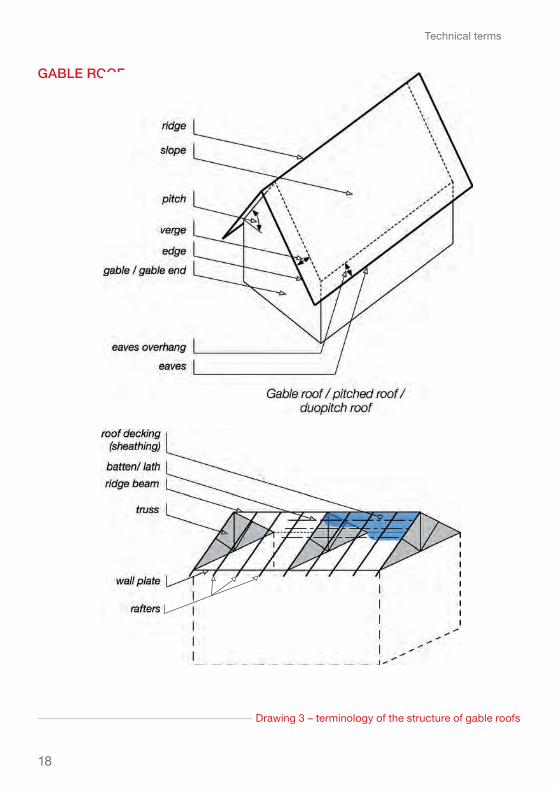
gAble roof
Drawing 3 – terminology of the structure of gable roofs
19
technical terms
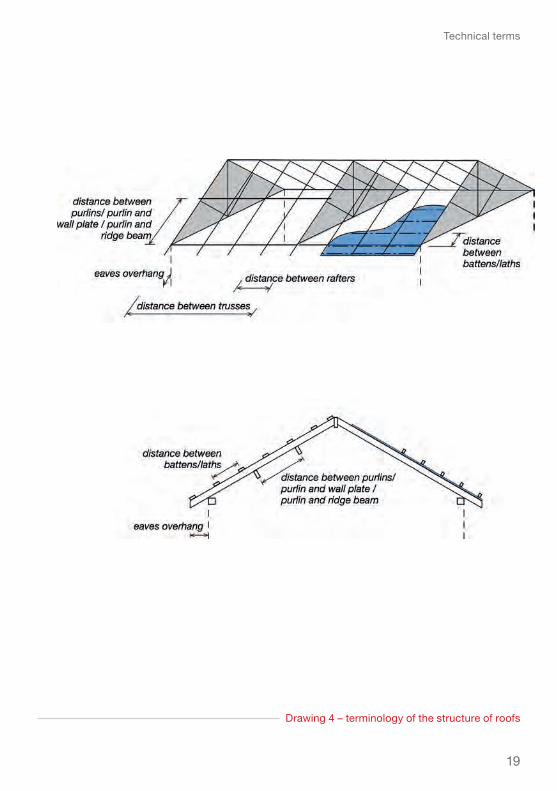
Drawing 4 – terminology of the structure of roofs

20
technical terms
hipped roof
Drawing 6 – terminology of the structure of hipped roofs

21
technical terms
gAmbrel roof

22
technical terms
mAteriAlS
Fixings / fasteners: roofing nail and roofing screw
Corrugated sheet materials
23
Glossary
AlphAbeticAl
Angle (hip/rafter): the sharp edge of a hipped roof from the ridge to the eaves where two sides meet. Also called hip angle.
Batten: wooden members to which the roof covering materials are attached.
Calliper: an instrument for measuring external or internal dimensions with two hinged legs resembling a pair of compasses and in-turned or out-turned points.
Coating thickness gauge: instrument that measures the thickness of the zinc coating through magnetic particle inspection.
Corrugated: shaped into alternate ridges and grooves, for added strength and rigidity.
Corrugated aluminium: aluminium sheet that has been rolled into a parallel wave pattern to impart stiffness.
Corrugated metal: metal sheet that has been rolled into a parallel wave pattern for stiffness and rigidity. A corrugated sheet acquires a stiffness which allows it to be self-supporting, that a flat sheet does not.
Corrugated roofing: corrugated metal or fiberglass mounted on rafters as roof covering.
Creep: gradual deformation of a roofing membrane due to thermal stress. Slow but continual permanent deformation of a material under sustained stress.
Cyclone: a system of violent winds rotat-ing inward to an area of low atmospher-ic pressure, with a counter-clockwise (northern hemisphere) or clockwise (southern hemisphere) circulation. This is usually called a hurricane in the Caribbean region and eastern Pacific Ocean, or typhoon in the region of the Indian or western Pacific oceans.
Eaves: the part of a roof that meets or overhangs the external walls of a build-ing. Protects the external wall from rain.
Eaves brace: a support between a wall and the eaves to increase the length of the overhang at the eaves.
Eaves bracket: a fixture on a wall to sup-port a long eaves overhang.
Eaves overhang: the portion of a roof that overhangs the external wall at the eaves.
Edges of the roof: consist of the eaves overhang, hip angle, verge and ridge.
End roof: edge of the roof at the top part of a single-pitch roof.
Fascia / fascia board: a wooden board or other flat piece of material such as that covering the ends of rafters. The fascia
glossary of terms

24
Glossary
Puncture resistance: resistance of the Cgi sheet to the perforation of the fas-tener heads under the effect of wind pressure (from inside) or wind suction (from outside). If the CGI sheet is not thick enough and hence the puncture resistance too low, the sheet will tear off around the fastener (roofing nail or screw) with its washer.
Purlin: (a) horizontal-framing members supporting the rafters or spanning truss-es that support the roof; (b) horizontal roof member sitting on the rafters or on a truss to which the roofing materials are directly attached.
Rafter: part of the framework of a pitched roof, one of the sloping members that supports battens and roofing materials.
Ridge: the line or edge formed where the two sloping sides of a roof meet at the top.
Roof covering: the external surface of the roof, normally the part that protects the structure from rain and other exter-nal elements. That weather-proof skin can be made from a membrane, thatch, slates, or sheeted material.
Roof framing: a group of members fitted or joined together to provide support for the roof covering.
Roofing nail: a special-purpose, short-threaded nail with a large head, usually galvanized or aluminium with a neoprene or plastic washer to aid in fastening roof coverings and provide improved sealing.
Roofing screw: long threaded screw used for fixing corrugated or profiled roofing sheets.
board also provides a suitable surface onto which the gutter can be fastened.
Fixing / fastener: nails, screws, bolts used for joining pieces of timber, bam-boo or other materials.
gable: the part of a wall that encloses the end of a pitched roof.
Gable end: a wall topped with a gable.
Galvanized: coated (iron or steel) with a protective layer of zinc.
Gauge: the thickness of sheet metal or wire.
Hurricane strap (seismic tie): metal con-nectors of various shapes, made of gal-vanized steel or stainless steel, used to strengthen the connections between the structural elements of a wooden frame, particularly the wooden roofs. Also called cyclone straps or ties.
Lath: see batten
Lumber: see timber
On edge: item such as lumber/timber laid on its edge (short side). The oppo-site of laid flat (broad side).
Overlap: the degree that something extends over something else. Roof tiles or sheets need to extend over each oth-er to ensure rain does not pass through.
Pitch: the angle of a sloping roof to the horizontal, measured in degrees (°).
Pressure: the positive wind pressure applied on the surface of a shelter.

25
Glossary
subjected to uplift forces (suction) from the wind or wind pressure (from inside if it is an open building).
Roof underlayment: membrane placed between the roof decking and the roof covering to provide a secondary water barrier.
Rubber washer: a flat ring of rubber used as a seal to minimize leakage.
Sealing washer: a soft neoprene (rubber) washer bonded to a metal backing made of galvanized steel or aluminium. Used to seal out air or water.
Service life of CGI sheet: duration of use of a CGI sheet until there is 5% corro-sion on its surface.
Slope: a surface of which one end or side is at a higher level than another.
Suction: the “negative” wind pressure applied on the surface of a shelter actu-ally resulting in a “pulling” force
Timber: the wood of trees cut and pre-pared for use as building material. Also called lumber.
Umbrella head: head of a nail, which is very wide and has an umbrella shape.
Verge: edge of a gable roof projecting over the gable end (wall). Can be flush with the gable end (wall) or can have an overhang.
Withdrawal resistance: characteristic of the adhesion of a material to another, as measured by the tensile force (per unit area) to be exerted on one of the two to separate one from the other. For example strength of the fasteners fixed to the support (e.g. the laths) to resist being pulled by the CGI sheet that is

26
Acronyms
ACQ: Alkaline Copper Quat (wood treatment)
ASTM: American Society for Testing and Materials (until 2001)
CA: Copper Azole (wood treatment)
CGI: Corrugated Galvanized Iron or steel
EN: european norm
FAO: Food and Agriculture Organization of the United Nations
ICRC: international Committee of the Red Cross
IFRC: international federation of the Red Cross and Red Crescent Societies
ISO: International Standard Organization
JIS: Japanese Industrial Standards
LOSP: Light Organic Solvent-borne Preservative (wood treatment)
OFDA: Office of United States Foreign Disaster Assistance
PRC: Philippines Red Cross
acronyms

27
Philippines: Haiyan response shelter model. (IFRC-SRU)

29
Section A - Materials / A.1 Corrugated Roofing Materials
This chapter focuses on the important performance specifications for CGI sheets, presents different materials used for the roof structure as well as the different fix-ings and accessories needed to securely fasten CGI sheets to construct a safe roof cladding.
A.1 corrugAted roofing mAteriAlSA whole variety of corrugated roofing materials have been devel-oped, such as corrugated bitu-men, fibreglass or cement sheets. The corrugation adds stability to the sheet or panel materials so they can span larger widths than traditional smaller sized roof cov-ering materials like for example tiles. As rather large surfaces can be covered per sheet this can result in material and cost sav-ings for the support structure and savings in installation time. Most of the corrugated sheets are light weight and considerably low cost. These properties make corrugat-ed materials in general particularly interesting for humanitarian shel-ter responses, in emergencies as well as for recovery and recon-struction.
The table 1 gives a brief overview of existing corrugated roofing materials available on the market, including a basic summary of their main advantages and disad-vantages.
Nepal: Hardware store offering different qualities and lengths
of CGI. (IFRC-SRU)
Section A – materIals

30
Section A - Materials / A.1 Corrugated Roofing Materials
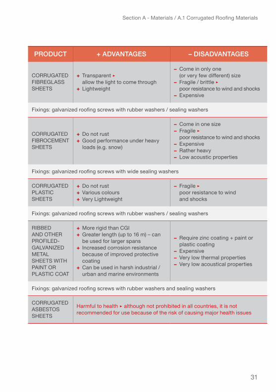
Table 1 – Advantages and disadvantages of various corrugated roofing materials
product + AdvAntAgeS – diSAdvAntAgeS
CoRRugated galvanized Steel Cgi SHeet (zinC Coating)
+ Comes in various thickness and sizes+ Lightweight + Easy to source+ Widely available+ Very low cost
− Limited durability; requires additional corrosion protection depending on the zinc coating thickness, especially when used in industrial/urban or marine environments− Very low thermal properties − Very low acoustical properties
Fixings: galvanized roofing nails or screws with rubber washers / sealing washers
CoRRugated aluMiniuM-zinC Coating SHeetS
+ Comes in various thickness and sizes+ Lightweight + improved corrosion resistance+ Can be used in industrial / urban environments
− More expensive than CGI− better thermal properties than Cgi− Very low acoustic properties− avoid contact with wood treated with copper sulphate (CA & ACQ), or any material made of copper, lead, brass or bronze
Fixings: aluminium roofing nails or screws with rubber washers / sealing washers
CoRRugated aluMiniuM SHeetS
+ Comes in various thickness and sizes+ Corrosion-resistant+ Very Lightweight+ Can be used in industrial / urban and marine environments
− Expensive− Very low thermal properties− Very low acoustical properties− avoid contact with wood treated with copper sulphate (CA & ACQ), or any material made of copper, lead, brass or bronze
Fixings: aluminium roofing nails or screws with rubber washers / sealing washers
CoRRugated bituMen SHeetS
+ Very resistant+ do not rust+ good thermal properties+ good acoustical properties+ Very low cost – comparable to CGI sheets with similar performance + Can be used in any environment, including marine and industrial / urban environments
− Come in only one (or very few different) size− Not (yet) widely available− Heavier than comparable Cgi sheets− Low resistance to fire ▹ recommended to place a sheathing underneath
Fixings: galvanized roofing screws with rubber washers / sealing washers
31
Section A - Materials / A.1 Corrugated Roofing Materials
product + AdvAntAgeS – diSAdvAntAgeS
CoRRugated fibReglaSS SHeetS
+ transparent ▹ allow the light to come through+ Lightweight
− Come in only one (or very few different) size− Fragile / brittle ▹ poor resistance to wind and shocks− Expensive
Fixings: galvanized roofing screws with rubber washers / sealing washers
CoRRugated fibRoCeMent SHeetS
+ do not rust+ Good performance under heavy loads (e.g. snow)
− Come in one size− Fragile ▹ poor resistance to wind and shocks− Expensive− Rather heavy− low acoustic properties
Fixings: galvanized roofing screws with wide sealing washers
CoRRugated PLASTIC SHeetS
+ do not rust+ various colours+ Very Lightweight
− Fragile ▹ poor resistance to wind and shocks
Fixings: galvanized roofing screws with rubber washers / sealing washers
Ribbed and otHeR PROFILED-galvanized Metal SHeetS witH PAINT OR PLASTIC COAT
+ More rigid than CGI + Greater length (up to 16 m) – can be used for larger spans+ increased corrosion resistance because of improved protective coating+ Can be used in harsh industrial / urban and marine environments
− Require zinc coating + paint or plastic coating− Expensive− Very low thermal properties− Very low acoustical properties
Fixings: galvanized roofing screws with rubber washers and sealing washers
CoRRugated aSbeStoS SHeetS
Harmful to health ▹ although not prohibited in all countries, it is not recommended for use because of the risk of causing major health issues

32
Section A - Materials / A.2 Corrugated Galvanized Iron or Steel (CGI) sheets
As of today, corrugated CGI sheeting is the most widely available worldwide provid-ing good performance at fairly low cost . It is used universally as roofing and clad-ding material for low cost and self-built housing and is also a very common material in humanitarian shelter response.
Some of the other types of corrugated roofing material, particularly bitumen, can be interesting alternatives to CGI sheeting in some contexts, especially if they become more widely available.
A.2 corrugAted gAlvAnized iron (cgi) or Steel (cgS) SheetS
CGI sheets are a well known material and widely available in most contexts, usu-ally at considerably low cost. Although steel is nowadays mostly used as base, CGI seems to be the most commonly known name for this material and is therefore used in this manual.
However, the quality of CGI sheets on the market in the different regions of the world vary greatly and to be aware of all the important performance criteria for putting together the right specifications for a given context can require expertise. This chap-ter presents all the important specifications of CGI sheeting, and the effect on the performance of the sheets (resistance to loads and durability) to help you make an informed choice.
CGI sheets are made of thin metal sheets, stiffened by corrugations. The corruga-tions, such as waves or folds, increase the strength and stiffness of the sheeting material considerably, without these waves, the sheets have limited load bearing capacity and are highly deformable. The sheets are made of mild steel, which is then galvanized to increase the resistance against corrosion and increase the durability or service life.
The quality and performance of a CGI sheet is determined by three main criteria:● For stability and resistance to loads first: its dimensions, especially its thickness and the type of corrugation.● For durability (resistance to corrosion) service life and appearance second: the type of galvanizing or Coating used.● For durability (resistance to corrosion) and service life third: the thickness of the galvanisation/coating on the sheet surface.
These three parameters are explained further in the coming sub-chapters. The weight per surface area (lb/ft2 or kg/m2) has less direct relevance for the per-formance of the sheet.

33
Section A - Materials / A.2 Corrugated Galvanized Iron or Steel (CGI) sheets
A.2.1. dimenSionS And meASurement for cgi SheetS
The important measurements that define a CGI sheet are:● the dimensions of the sheet: length and width (after corrugation)● the thickness● the corrugations
Depending on the region the dimensions are indicated in metric system or imperial system.
widths most commonly used in imperial system are 30 in (762 mm), 36 in (914 mm) and 42 in (1067 mm)
lengths range from 6 ft (1.83 m) up to 20 ft (6 m) in imperial and from 1.65 m to 5 m in the metric system
thickness is commonly expressed in gauge, from 32 gauge (0.34 mm) to 24 gauge (0.701 mm)The lower the gauge, the thicker the CGI sheet. Gauge size standards were developed based on the weight per surface (m2 or ft2) of the sheet for a given material (steel, galvanized steel, alu-minum, etc.) and therefore the equivalent thick-nesses in mm or inches differ for each material. See Annex 1 – for more information on gauge and conversion.
dimensions of corrugations Cgi sheet basic measurements based on eiC● Corrugation pitch = 79 mm● Corrugation depth = 18 mm● Ray of arch = 24 mm● Number of corrugation pitch = 11 for a 36” sheet (width = 914 mm)● Number of crests (corrugations) = 12
Cgi sheet dimensions
Consider the available sizes of CGI sheeting when designing a shelter. Ideally the full slope of the roof should be covered with one full length sheet, in order to use the material most economically (minimum of overlaps) and avoid extra work for cutting.

34
Section A - Materials / A.2 Corrugated Galvanized Iron or Steel (CGI) sheets
comparison of different cgi sheet thicknesses and related quality/performance:
The thickness or gauge is the most relevant criteria for the resistance of the CGI sheet to “pulling” forces like suction under strong wind. The gauge together with the type of corrugation is also the most relevant for stability and resistance to oth-er loads. The table below gives a non-exhaustive overview of some common CGI sheets found in the market, with an indicative list of advantages and disadvantages.In the advantages column there is indicated which category of cyclone each can be expected to resist.
Some further information is given if there is need for additional sealing washers, or a risk of creep (deformation) of the material.
Table 2 – Advantages and disadvantages of various CGI sheet thickness
*For explanation on the different categories of cyclones see Section C of the manual
When carrying out roof repairs on existing CGI roofs, make sure to purchase CGI sheets with same measurements of corrugations as the roof-sheets already used on the roof otherwise they will not overlap properly! Consequently, the roof may leak!
This indication is based on calculations of a supporting roof structure with distances of 60cm between laths/battens and a fixing providing 38mm penetration depth. If the distance between the laths is higher than 60 cm and/or the penetration depth of the fixings used is lower than 38 mm then the CGI sheet roof is unlikely to resist the category of cyclones indicated in the table. If you have a distance between laths/battens smaller or larger than 60 cm, you can confirm the appropriate thickness of the CGI sheet by using the Excel spreadsheet – Roof Estimate Form in Annex 7.
Cgi sheet dimensions

35
Section X / Title of Chaptercgi Sheet
thick-neSS
+ AdvAntAgeS & cYclone reSiStAnce – diSAdvAntAgeS
32 gauge /0.340 mm
(and lower / thinner to as thin as 0.15
mm! )
+ Very low price– will not resist strong winds or cyclones
– Thickness too low to provide enough stability to the roof covering– High risk of CGI sheet puncturing/ripping off during strong winds– Risk of creep ▹ zinc coating will not last long
30 gauge / 0.399 mm
+ low price+ minimum thickness for use as roof covering shelters + Can resist maximum a category-1* cyclone without additional sealing washers for roofing nails+ Should resist a category-3 cyclone with additional sealing washers
– High risk of CGI sheet tearing or “unbuttoning” around the nails in Category 2 or higher cyclones ▹ requires additional sealing washers (22mm-diameter for roofing nails and 35mm-diameter for roofing screws)– Risk of creep ▹ zinc coating will not last long
28 gauge / 0.475 mm
+ acceptable resistance to puncture▹ do not need additional sealing washers for roofing nails+ low price+ Can resist a category-2 cyclone without additional sealing washers for roofing nails+ Can resist a category-3 cyclone with additional sealing washers
– Requires additional sealing washers (27 mm-diameter) for roofing screws in order to resist a category-3 cyclone– Risk of creep ▹ zinc coating will not last long
26 gauge / 0.551 mm
+ good resistance to puncture ▹ do not need additional sealing washers for roofing nails+ Recommended in most Caribbean countries, placed over a roof decking+ Can resist a category-2 cyclone without additional sealing washer for roofing nails+ Can resist a category-3 cyclone with additional sealing washers
– Expensive price (in the range of up to 150% of the price of a 30 gauge or 0.4mm sheet)– Requires additional sealing washers (25 mm-diameter) for roofing screws in order to resist a category-3 cyclone
25 gauge / 0.627 mm
+ Very good resistance to puncture ▹ do not need additional sealing washers for roofing nails+ Complies with european standards+ Can resist a category-3 cyclone with roofing screws and 20mm-diameter sealing washers
– Expensive price (in the range of up to 150% of the price of a 30 gauge or 0.4mm sheet)– Requires additional sealing washers (22 mm-diameter) for roofing screws
24 gauge / 0.701 mm
+ Excellent resistance to puncture ▹ do not need additional sealing washers for roofing nails+ Recommended in most Caribbean countries+ Can resist a category-4 cyclone with roofing screws + 20mm-diameter sealing washers
– Very expensive price (around double the price of a 30gauge or 0.4mm sheet)– Requires additional sealing washers (20 mm-diameter) for roofing screws

36
Section A - Materials / A.2 Corrugated Galvanized Iron or Steel (CGI) sheets
A.2.2 tYpe of gAlvAnizAtion or coAting
Galvanizing is the process of coating iron or steel with zinc in order to provide greater protection against corrosion. The most common methods for applying protective zinc coating to iron and steel are, hot dip galvanizing, electro-galvanizing, sherardizing, metallic spraying, and painting with zinc-rich paint.
hot-dip galvanizing:The corrugated steel sheet (base steel) is dipped in a molten zinc bath, as the hot-dip galvanizing process. A zinc layer is depos-ited on the surface of the steel sheet and an iron-zinc alloy layer is formed to protect the steel sheet against corrosion. Hot-dip galvani-zation is the most effective method to protect steel against corrosion.
The durability of the CGI sheets depends mainly on the zinc coating thickness deposited on the surface of the steel sheet, but, also on the galvanizing process employed. Hot dip galvanizing provides a rough finish by depositing more zinc than other Schematic section of a hot dip galvanized coating*
If you want to go for thinner CGI sheet you will need to reduce the dis-tance between the laths and/or use larger sealing washers and more fix-ings in order to achieve the same level of resistance to uplift and suction forces. It means more materials for the roof structure and more fixings/accessories, thus increasing costs for the structure.
0.399 mm (30-gauge) is the minimum thickness of CGI sheet that should be used to cover a shelter. 0.475 mm (28-gauge) or 0.551 mm (26-gauge) CGI sheets can be a good solution for covering transitional, progres-sive or core shelters especially in cyclone prone regions When building permanent shelters, it is important to respect the local building codes which may require thicker CGI sheets.

37
Section A - Materials / A.2 Corrugated Galvanized Iron or Steel (CGI) sheets
methods, resulting in very high corrosion resistance. This is necessary when using the sheets on some acidic or treated lumber as well as in marine or urban environ-ments (where pollution can increase corrosion).
painting with zinc-rich paint:When using a zinc-rich paint, a paint layer about 2 times thicker than the zinc coating applied during a hot-dip galvanizing will be needed to achieve the same protection and will finally be more costly.
● Painting with zinc-rich paint can be an adequate method for “repairing” aging CGI sheets. (See also Chapter E – Roof maintenance and preventive measures.)
Alternative coatings for cgi sheetsIn environments where the atmosphere is harsh, especially in coastal areas or in highly industrialized or urban areas the use of CGI sheets is not the most effective. In these areas, it is generally recommended to use roofing steel sheets coated with a stronger protection against corrosive conditions (e.g., sulphur dioxide pollution and airborne salinity).
Besides zinc coating – classified as Z (zinc coating used for CGI sheets), there are other types of protective coating of the steel sheet (base steel), including:
● Zinc-Aluminium – classified as ZA ▹ zinc + 5 % aluminium● Aluminium-Zinc – classified as AZ ▹ 55% aluminium, 1.6% silicium + zinc● Aluminium – classified as AL● Stainless – classified as Z8 C17 ▹ ferritic stainless steel with 17% chromium
Advantages and disadvantages of each type of coating:In some environments, hot-dip galvanized CGI might not be the most appropriate. The table 3 should help you check if the Zinc coating is the most adapted to your environment or if you should consider choosing a more suitable type of coating.
* © The Engineers and Architects’ Guide: hot-dip galvanizing, Galvanizers Association UK
Hot dip galvanizing delivers the best results for CGI sheets, as well as its accessories, fasteners and hurricane straps. Other methods provide far less corrosion resistance and durability. (For more information on galva-nizing methods, see Annex 7 – Library and further reading.)

38
Section A - Materials / A.2 Corrugated Galvanized Iron or Steel (CGI) sheets
CGI sheets with a zinc coating are generally the most cost efficient choice when building in rural or suburban areas located at least 800m from the shore. In coastal or highly polluted urban or industrialized areas, other types of coatings may be more suitable but also more expensive.
item + AdvAntAgeS – diSAdvAntAgeS
zinC Coating (z) + Most widespread+ Less expensive
– Service life very limited in industrial or polluted urban and marine environments
zinC-aluMiniuM Coating (za)
+ increases the hardness of the Cgi sheet
– Service life limited in industrial or polluted urban and marine environments– Expensive
aluMiniuM-zinC Coating (az)
+ increases the hardness of the Cgi sheet
– Service life limited in industrial or polluted urban and marine environments– Expensive
zinC Coating (z) WITH PAINT OR PLASTIC
+ increased resistance to corrosion+ Recommended for industrial or polluted urban environments+ Can be used in marine environments (mandatory to check with supplier)
– Expensive
aluMiniuM Coating (al)
+ increased resistance to corrosion+ Recommended for marine environments
– Very expensive
StainleSS
+ Does not need any protection or finishing+ does not rust+ ideal for marine environments
– Extremely expensive– Considered as high-end product
Table 3 – Advantages and disadvantages of each type of coating
39
Section A - Materials / A.2 Corrugated Galvanized Iron or Steel (CGI) sheets
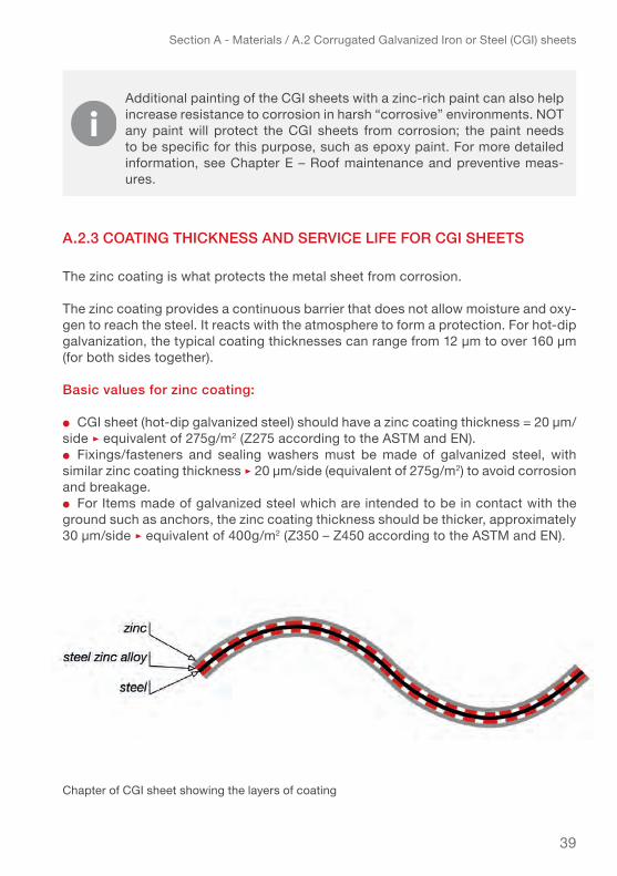
A.2.3 coAting thickneSS And Service life for cgi SheetS
The zinc coating is what protects the metal sheet from corrosion. The zinc coating provides a continuous barrier that does not allow moisture and oxy-gen to reach the steel. It reacts with the atmosphere to form a protection. For hot-dip galvanization, the typical coating thicknesses can range from 12 µm to over 160 µm (for both sides together).
basic values for zinc coating:
● CGI sheet (hot-dip galvanized steel) should have a zinc coating thickness = 20 µm/side ▹ equivalent of 275g/m2 (Z275 according to the ASTM and EN).● Fixings/fasteners and sealing washers must be made of galvanized steel, with similar zinc coating thickness ▹ 20 µm/side (equivalent of 275g/m2) to avoid corrosion and breakage.● For Items made of galvanized steel which are intended to be in contact with the ground such as anchors, the zinc coating thickness should be thicker, approximately 30 µm/side ▹ equivalent of 400g/m2 (Z350 – Z450 according to the ASTM and EN).
Chapter of CGI sheet showing the layers of coating
Additional painting of the CGI sheets with a zinc-rich paint can also help increase resistance to corrosion in harsh “corrosive” environments. NOT any paint will protect the CGI sheets from corrosion; the paint needs to be specific for this purpose, such as epoxy paint. For more detailed information, see Chapter E – Roof maintenance and preventive meas-ures.

40
Section A - Materials / A.2 Corrugated Galvanized Iron or Steel (CGI) sheets
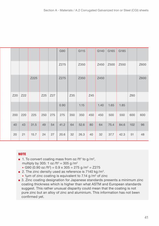
Below table provides the different values for zinc coating mass and zinc coating thickness in µm according to the ASTM, European and Japanese standards.
Table 4 – Conversion table for equivalence of zinc coating mass and thickness according to standards
ASTM Standards(ASTM A653 / A653M) Zinc coating designation (inch-pound)
G30 G40 G60 G90 G115 G140 G165 G185
ASTM Standards(ASTM A653 / A653M) Zinc coating designation (SI metric)
Z90 Z120 Z180 Z275 Z350 Z450 Z500 Z550 Z600
Chapitre 1 european StandardsChapitre 2 (EN ISO 10346)Chapitre 3 Zinc coating designation (SI metric)
Z100 Z150 Z225 Z275 Z350 Z450 Z600
Japanese Standards (JIS G3302)Zinc coating designation (SI metric)
Z08 Z10 Z12 Z18 Z20 z22 Z25 Z27 Z35 Z45 Z60
Minimum coating mass (oz/ft2) for both sides
0.30 0.40 0.60 0.90 1.15 1.40 1.65 1.85
Minimum coating mass (g/m2) for both sides
80 90 100 100 120 120 150 180 180 200 220 225 250 275 275 350 350 450 450 500 550 600 600
Minimum zinc coating thickness (µm) for both sides
17 13.8 21 14 26 18.2 21 34 27.4 40 43 31.5 49 54 41.2 64 52.6 80 64 75.4 84.6 102 96
Minimum zinc coating thickness (µm) for one side
8 6.9 10 7 13 9.1 10.5 17 13.7 20 21 15.7 24 27 20.6 32 26.3 40 32 37.7 42.3 51 48
41
Section A - Materials / A.2 Corrugated Galvanized Iron or Steel (CGI) sheets
ASTM Standards(ASTM A653 / A653M) Zinc coating designation (inch-pound)
G30 G40 G60 G90 G115 G140 G165 G185
ASTM Standards(ASTM A653 / A653M) Zinc coating designation (SI metric)
Z90 Z120 Z180 Z275 Z350 Z450 Z500 Z550 Z600
Chapitre 1 european StandardsChapitre 2 (EN ISO 10346)Chapitre 3 Zinc coating designation (SI metric)
Z100 Z150 Z225 Z275 Z350 Z450 Z600
Japanese Standards (JIS G3302)Zinc coating designation (SI metric)
Z08 Z10 Z12 Z18 Z20 z22 Z25 Z27 Z35 Z45 Z60
Minimum coating mass (oz/ft2) for both sides
0.30 0.40 0.60 0.90 1.15 1.40 1.65 1.85
Minimum coating mass (g/m2) for both sides
80 90 100 100 120 120 150 180 180 200 220 225 250 275 275 350 350 450 450 500 550 600 600
Minimum zinc coating thickness (µm) for both sides
17 13.8 21 14 26 18.2 21 34 27.4 40 43 31.5 49 54 41.2 64 52.6 80 64 75.4 84.6 102 96
Minimum zinc coating thickness (µm) for one side
8 6.9 10 7 13 9.1 10.5 17 13.7 20 21 15.7 24 27 20.6 32 26.3 40 32 37.7 42.3 51 48
note● 1. To convert coating mass from oz / ft2 to g / m2, multiply by 305: 1 oz / ft2 = 305 g / m2 ▹ G90 (0.90 oz / ft2) = 0.9 x 305 = 275 g / m2 = Z275● 2. The zinc density used as reference is 7140 kg / m3. ▹ 1µm of zinc coating is equivalent to 7.14 g / m2 of zinc● 3. Zinc coating designation for Japanese standards presents a minimum zinc
coating thickness which is higher than what ASTM and European standards suggest. This rather unusual disparity could mean that the coating is not pure zinc but an alloy of zinc and aluminium. This information has not been confirmed yet.
42
Section A - Materials / A.2 Corrugated Galvanized Iron or Steel (CGI) sheets
The choice of the zinc coating thickness depends on the environment (atmosphere) and the desired service life period for the CGI sheets.
environment (atmosphere) impact on service life of cgi sheets:
The levels of corrosion caused by the different environmental impacts (e.g. humidity, salinity and acidity of the air) is classified into 6 categories.
Table 5 – classification of level of corrosivity based on environment
The “service life” is defined as the time corresponding to the period of use of the CGI sheet until it is covered with 5% corrosion. The lifespan of the CGI sheet corresponds to the period during which the CGI sheet is used until it loses its mechanical characteristics and begins the constructive degradation (more than 5% corrosion). The service life can be extended if the CGI sheet undergoes a treatment such as the application of a special zinc paint once it is has about 5% corroded.

43
Section A - Materials / A.2 Corrugated Galvanized Iron or Steel (CGI) sheets
cAtegorY of corroSion
level of corroSivitY
environment (outdoor AtmoSphere)
C1 • Very low
• Dry or cold regions atmospheric condition with very low levels of pollution and periods of moisture, e.g., some deserts, central Arctic/Antarctic
C2 • low
• Temperate regions atmospheric condition with low pollution (So2 below 5 µg/m3), e.g., rural areas, small towns• Dry or cold regions atmospheric condition with short periods of moisture, e.g., deserts, sub-arctic regions
C3 • Medium
• Temperate regions atmospheric condition with medium pollution (So2: 5 to 30 µg/m3) or influence of chlorides, e.g., urban areas, coastal areas with low deposit of chlorides• Sub-tropical and tropical regions atmospheric condition with low pollution (So2 below 5 µg/m3)
C4 • High
• Temperate region atmospheric condition with high pollution (SO2: 30 to 90 µg/m3) or substantial influence of chlorides, e.g., polluted urban areas, coastal areas without salt spray, severe exposure to de-icing salts• Sub-tropical and tropical regions (very long periods of moisture), atmospheric condition with medium pollution (So2: 5 to 30 µg/m3)
C5 • Very high
• Temperate and sub-tropical regions atmospheric condition with very high pollution (So2: 90 to 250 µg/m3) and/or strong influence of chlorides, e.g., industrial areas, coastal areas
CX • Extreme
• Sub-tropical and tropical regions (very long periods of moisture), atmospheric condition with very high pollution (SO2 above 250 µg/m3), including associated pollution and production and/or strong influence of chlorides, e.g., highly polluted industrial areas, coastal and offshore areas and contact with salt spray
44
Section A - Materials / A.2 Corrugated Galvanized Iron or Steel (CGI) sheets
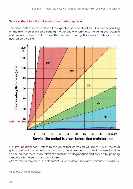
Service life in function of environment (atmosphere):
The chart below helps to define the expected service life of a CGI sheet depending on the thickness of the zinc coating, for various environments including sub-tropical and tropical zones. Or to chose the required coating thickness in relation to the desired service life.
* “First maintenance1” refers to the point that corrosion will be of 5% of the total galvanized surface. At such a percentage, the alteration of the steel (base) will still be so limited that there is no relevant constructive degradation and service by painting can be undertaken in good conditions.▹ For further information, see Chapter E – Roof maintenance and preventive measures.
1 Source: Zink Info Benelux
45
Section A - Materials / A.2 Corrugated Galvanized Iron or Steel (CGI) sheets
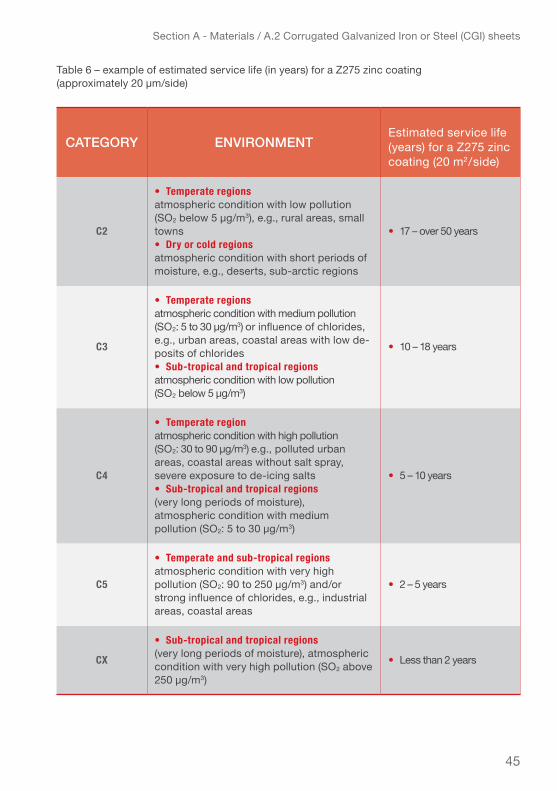
cAtegorY environmentestimated service life (years) for a Z275 zinc coating (20 m2/side)
C2
• Temperate regions atmospheric condition with low pollution (So2 below 5 µg/m3), e.g., rural areas, small towns• Dry or cold regions atmospheric condition with short periods of moisture, e.g., deserts, sub-arctic regions
• 17 – over 50 years
C3
• Temperate regions atmospheric condition with medium pollution (So2: 5 to 30 µg/m3) or influence of chlorides, e.g., urban areas, coastal areas with low de-posits of chlorides• Sub-tropical and tropical regions atmospheric condition with low pollution (So2 below 5 µg/m3)
• 10 – 18 years
C4
• Temperate region atmospheric condition with high pollution (So2: 30 to 90 µg/m3) e.g., polluted urban areas, coastal areas without salt spray, severe exposure to de-icing salts• Sub-tropical and tropical regions (very long periods of moisture), atmospheric condition with medium pollution (So2: 5 to 30 µg/m3)
• 5 – 10 years
C5
• Temperate and sub-tropical regions atmospheric condition with very high pollution (So2: 90 to 250 µg/m3) and/or strong influence of chlorides, e.g., industrial areas, coastal areas
• 2 – 5 years
CX
• Sub-tropical and tropical regions (very long periods of moisture), atmospheric condition with very high pollution (SO2 above 250 µg/m3)
• Less than 2 years
Table 6 – example of estimated service life (in years) for a Z275 zinc coating (approximately 20 µm/side)

46
Section A - Materials / A.2 Corrugated Galvanized Iron or Steel (CGI) sheets
According to the European standards (EN ISO 14713), each zinc coating thickness has a minimum service life as indicated in the table below.
Table 7 – minimum service life (in years) per zinc coating thickness
In order to obtain more precise results on CGI sheet service life or on the zinc coat-ing thickness to be applied to the metal sheet, you can also use the online tool created by Dr. X.G. Zhang, the Zinc Coating Life Predictor. This tool estimates the corrosion rate of zinc in various environments, and directly on the location of the site. It also provides some examples of corrosion rate and coating life for various environments, as well as information about where to find data. It is accessible at: http://www.galvinfo.com:8080/zclp/.
* Source: European General Galvanizers Association
tYpe of zinc coAting
zinc coAting
thickneSS
minimum Service life (YeArS) per tYpe of environmentS(en iSo 14713)
(en iSo 10346)
per Side (µm) c3 c4 c5 cX
Z100 7 3 years 2 years 0 0
Z150 10 5 years 3 years 1 year 0
Z225 15 7 years 4 years 2 years 0
Z275 19 10 years 5 years 3 years 0
Z350 24 12 years 6 years 4 years 1 year
Z450 31 15 years 7 years 4 years 1 year
Z600 41 20 years 10 years 5 years 2 years
Research* over many years has shown that the life of the zinc coating is near directly proportional to the zinc coating thickness. So doubling the zinc coating thickness will double the life of the coating and the service life of the CGI sheet.
47
Section A - Materials / A.2 Corrugated Galvanized Iron or Steel (CGI) sheets
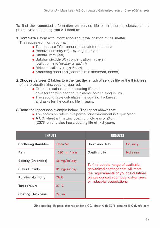
To find the requested information on service life or minimum thickness of the pro tec tive zinc coating, you will need to:
1. complete a form with information about the location of the shelter. The requested information is:
● Temperature (°C) - annual mean air temperature● Relative humidity (%) – average per year● Rainfall (mm/year)● Sulphur dioxide SO2 concentration in the air (pollution) (mg/m2.day or µg/m3)● Airborne salinity (mg/m2.day)● Sheltering condition (open air, rain sheltered, indoor)
2. choose between 2 tables to either get the length of service life or the thickness of the protective zinc coating required.
● One table calculates the coating life and asks for the zinc coating thickness (on one side) in µm. ● The second table calculates the coating thickness and asks for the coating life in years.
3. read the report (see example below). The report shows that:● The corrosion rate in this particular environment is 1.7µm/year.● A CGI sheet with a zinc coating thickness of 24µm (Z275) on one side has a coating life of 14.1 years.
Zinc coating life predictor report for a CGI sheet with Z275 coating © Galvinfo.com
inPuts Results
Sheltering condition open air corrosion rate 1.7 µm / y
rain 1820 mm / year coating life 14.1 years
Salinity (chlorides) 56 mg / m2.dayTo find out the range of available galvanized coatings that will meet the requirements of your calculations please consult your local galvanizers or industrial associations.
Sulfur dioxide 31 mg / m2.day
relative humidity 79 %
temperature 27 °C
coating thickness 24 µm

48
Section A - Materials / A.2 Corrugated Galvanized Iron or Steel (CGI) sheets
A. 2.4 eXAmple technicAl SpecificAtionS for cgi SheetS
Specifications from the IFRC Emergency Items Catalogue2
Table 8 – CGI sheet technical specifications from EIC (as of 2016, due to be updated)
2 Link to EIC CGI sheet: http://procurement.ifrc.org/catalogue/detail.aspx?volume=1&groupcode=111&familycode=111003&categorycode=BSHE&productcode=EBUIBSHE
item required vAlue deScription / note
Steel (base)● Mild steel for forming● Cold rolled steel sheet● Cold forming
Grade• DX 51 D+Z • SgCC• CS
According to the following standards:• European standard EN 10346 (2009)• Japanese standard JIS G3302• ASTM standard ASTM A653
Yield strength • 220 MPa (N/mm2) • Minimum 220 MPa (N/mm2)
Tensile strength • 300 MPa (N/mm2) • Minimum 270 MPa (N/mm2)• Maximum 500 MPa (N/mm2)
Galvanization method • Hot-dip continuous
• Hot-dip galvanizing provides the best protection for CGI sheets. Other methods should be avoided.According to standards:• European standard EN 10346 (2009)• Japanese standard JIS G3302• ASTM standard ASTM A653
Protective coating • zinc• Other coatings exist, such as aluminium-zinc, zinc-aluminium or aluminium. More details are provided further on.
Zinc coating thickness
• Z275 (ASTM A653 or • EN 10346) ▹ 275 g/m2 (40 μm > 20µm/side)
• A minimum of 137.5 g/m2 on each side is recommended ▹ Should be chosen according to the desired service life and environment

49
Section A - Materials / A.2 Corrugated Galvanized Iron or Steel (CGI) sheets
Table 8 – CGI sheet technical specifications from EIC
item required vAlue deScription / note
Thickness
• 26 gauge (0.551 mm) for permanent shelters• 28 gauge (0.475 mm) for transitional shelters• 30 gauge (0.399 mm) for temporary shelters
• 30 gauge is the minimum thickness for covering shelters• Minimum thickness requirement for:• European standards: 0.63 mm (25 gauge)• Caribbean recommendations: 0.551 – 0.701 mm (26 – 24 gauge)
Length (imperial system)
6 ft (1.83 m), 8 ft (2.44 m), 10 ft (3.05 m) • Most common from 6 – 20ft (1.83–6.00 m)
Length (metric system) 2.00 m, 2.50 m, 3.00 m • Most common from 1.65 – 5.00 m (5.5–18.6 ft)
Width after corrugation
● 914 mm (36 in) ● Most common from 762–1067 mm (30–42 in)
Number of corrugation pitch
● 11 corrugation pitch
Number of crest (corrugation) 12 crestsCorrugation depth
● 18 mm
Corrugation pitch ● 79.2 mm
Weight (kg/m2) ● Approx. 4.322 kg/m2
● For a 26-gauge CGI sheet.● Depends on thickness of the zinc coating.● For other thicknesses, equivalence is provided in Annex 1.
Service life (life expectancy)
● depends on the environment
● Possible to increase the zinc coating thickness in order to increase the service life of the Cgi sheetsAccording to standards:● Standard ISO 14713-1 & ISO 14713-2
Availability
● Specs in the Emergency Items Catalogue > Worldwide
● See link in footnote

50
Section A - Materials / A.2 Corrugated Galvanized Iron or Steel (CGI) sheets
A.2.5. problemS with cgi SheetS And preventive meASureS
The major problem with CGI sheets is corrosion. Other problems are mechanical and physical deterioration and failure of fixings/fasteners, mainly due to weather, heat or extra loading.
corrosion
The resistance to corrosion of the steel depends primarily on the type of galvanization, the thickness of the protective zinc coating and the environment in which the CGI sheets are used. Corrosion may be caused by:
● acids found in rainwater, condensation, dew, etc.● strong alkalis (such as sodium from seawater)● sulphuric acids produced by pollution in urban environments or industrial areas
(hydrogen sulphide and sulphur dioxide)
Coastal area Kalapata, Bangladesh: Corroded CGI roofing. (IFRC-SRU)

51
Section A - Materials / A.2 Corrugated Galvanized Iron or Steel (CGI) sheets
different types of corrosion affecting cgi sheets:
1. natural corrosion: the zinc coating deposited on the metal sheet develops a natural corrosion on its surface from exposure to the atmosphere and by the action of the weather. It thus ensures protection of the steel sheet (base steel). However, after a certain period of time, which varies depending on the environment, the zinc coating becomes too corroded to be able to protect the steel any longer.
2. chemical corrosion: is caused by chemical reaction between two (or more) materials in contact with each other. Galvanized steel has a good corrosion resistance to certain materials, including concrete, lead, tin, stainless steel, zinc and aluminium. However, it has a low corrosion resistance to other materials, such as plasters and wet cement mortar (especially portland cement), tannins of some types of woods (e.g., redwood, cedar, oak, chestnut) and wood preservatives containing copper, such as Copper Azole (CA) and Alkaline Copper Quaternary (ACQ). Zinc and galvanized steel items in contact with the highly corrosive materials as listed above, are likely to suffer additional of faster corrosion!
3. galvanic corrosion: the galvanized steel in contact with certain metals, such as copper, pure steel, pure iron, bronze, nickel, chromium, and additionally in contact of water (rainwater, condensation, dew) creates electrolytic reaction causing the acceleration of the zinc coating corrosion.
measures to avoid corrosion problems:
natural corrosion: ● Use sheets with a protective zinc coating thick enough to resist the environment
where it is used. (See charts environment impact on service life on page 44)
chemical corrosion:● Avoid galvanized steel contact with corrosive materials mentioned above.● Use only hot-dip galvanized steel and stainless steel (for CGI sheets, fixings/fas-
teners, hurricane straps), both can withstand the harsh chemicals and slow the corrosion rate.
galvanic corrosion:● Avoid contact with copper, pure steel, pure iron, bronze, nickel, chromium and
alloys made of those metals.● Apply a protective coat of paint on galvanized steel.● Avoid contact between galvanized steel and stainless steel. Using dissimilar
metals can cause loss of galvanization and protection.

52
Section A - Materials / A.2 Corrugated Galvanized Iron or Steel (CGI) sheets
mechanical and physical deterioration:
Mechanical and physical deterioration of CGI sheets can be caused by scratches and impacts on the zinc coating, the expansion – contraction cycle under the effect of temperature, creep (slow deformation) of the CGI sheets under their own weight and the deformations due to excessing loading (live or dead loads).
Such types of deterioration damages the protective zinc coating and therefore accel-erates the corrosion of the metal sheet (base steel).
Measures to avoid damage and ensure service life:– Avoid scratches e.g. from contact with sharp tools or materials– Choose a sufficiently thick CGI sheet ▹ avoid Cgi sheets whose
thickness is less than the recommendations, i.e., 0.399 mm to 0.551 mm (30 – 26 gauge)
– Ensure sufficiently tight spacing of the support structure in function of the CGI thickness
– Avoid walking on the roof, unless necessary– Avoid putting heavy weights on the CGI sheets, especially objects with
sharp edges (e.g. concrete blocks) that risk scratching and damaging the sheets.
– use zinc paint for maintenance of minor corrosion to extend service life
Corroded steel truss and CGI with white rust. (IFRC-SRU)
53
Section A - Materials / A.2 Corrugated Galvanized Iron or Steel (CGI) sheets
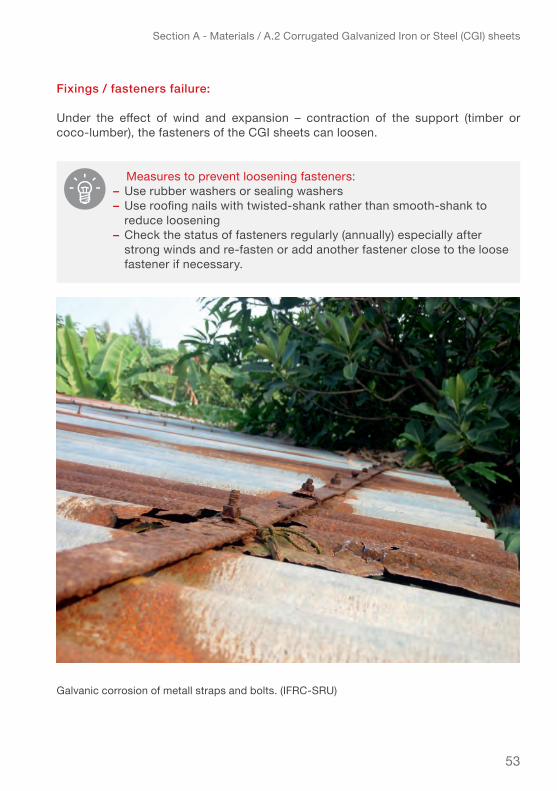
fixings / fasteners failure:
Under the effect of wind and expansion – contraction of the support (timber or coco-lumber), the fasteners of the CGI sheets can loosen.
Measures to prevent loosening fasteners:– Use rubber washers or sealing washers– Use roofing nails with twisted-shank rather than smooth-shank to
reduce loosening– Check the status of fasteners regularly (annually) especially after
strong winds and re-fasten or add another fastener close to the loose fastener if necessary.
Galvanic corrosion of metall straps and bolts. (IFRC-SRU)

54
Section A - Materials / A.3 Materials for the structural support of CGI roofs
A.3 mAteriAlS for the StructurAl Support of cgi roofS
This Chapter presents some of the most common types of materials used as sup-port (laths / battens of the roof structure) to which the CGI sheets can be fastened. You will find basic mechanical properties specified for the presented sample materi-als, overviews of dimensions and sections used in construction and other practical guidance. At the end a table summarizes main advantages and disadvantages of the different materials.
Your choice will depend on availability, affordability and cultural acceptability of the material and of course on its technical performance of providing a good withdrawal resistance in order to ensure secured fixings of the CGI sheets.
The following materials are commonly used as support laths / battens and presented in this chapter:
1 Lumber / timber2 Coconut wood3 bamboo 4 Metal
Jamaica, hurricane Dean, 2008: Truck delivering lumber and other construction materials. (© french Red Cross)

55
Section A - Materials / A.3 Materials for the structural support of CGI roofs
A.3.1. lumber / timber
Timber is classified as hardwood or softwood. As the name indicates, hardwood is harder than softwood. Hardwood is less commonly used for construction than soft-woods. Softwoods, especially species such as pine, Douglas fir, spruce, hemlock, larch, are widely used in construction, particularly as structural elements. You will always need to check locally which woods are commonly available and used for construction.
In this chapter pine will be used as exemplary as one of the most commonly used softwoods in construction.
mechanical properties of softwoods:the table below presents the mechanical properties and basic information about wood treatment and life expectancy for pine, common softwood that can be used as construction lumber/timber. Look for similar performance properties when selecting timber for construction.
Haiti: Timber in a construction materials shop. (IFRC-SRU)

56
Section A - Materials / A.3 Materials for the structural support of CGI roofs
table 9 – mechanical properties of pine
* Source: Timber, Durability and External Applications, Australian Timber Importers Federation, www.timber.net.au
Softwood LUMBER (PINE)
REQUIRED VALUES / DESCRIPTION
Species • Pine• Species with similar properties, e.g. spruce, hemlock, larch
Moisture content • 12%
Modulus of elasticity E (MPa) • 8,000 – 10,000 MPa
Specific gravity G • 0.30 – 0.59
Static bending – modulus of rupture (MPa) • 50 – 80 MPa
Compression strength paral-lel to grain (MPa) • 40 MPa
Compression strength perpendicular to grain (MPa) • 5.6 MPa
Shear parallel to grain (MPa) • 9 MPa
Tension strength perpendicular to grain (MPa) • 2 – 3 MPa
Fixings/fasteners • Hot-dip galvanized roofing nails / screws• Stainless steel roofing nails / screws
Possible treatment:
pressure treatment with:• Copper Azole (CA) – arsenic-free preservative• Alkaline Copper Quaternary (ACQ)• Light Organic Solvent-borne Preservative (LOSP) – LOSP-treated timber is not suitable for in-ground use. two possible methods:• wood autoclaved• Wood treated by dipping (less durable than wood autoclaved)
Life expectancy*:
the life expectancy of treated wood products depends on:• wood quality (class 1 to 4)• type of chemical used • chemical depth of penetration (depends on treatment methods)• danger of exposure (insects, fungi, termites) natural durability (without treatment) – class 4:• 5 – 8 years for use above-ground• 0 – 5 years for use in-ground with appropriate wood treatment: over 50 years
57
Section A - Materials / A.3 Materials for the structural support of CGI roofs
Section sizes of lumber/timberLumber has various sizes which can used as supports for CGI sheets. The table 9 uses lumber sizes for structural construction, according to the ASTM3 standards to give an idea what dimensions can be used.
Various factors should be taken into consideration when choosing the suitable dimensions for laths/battens. The thickness of the laths/battens is relevant for the penetration depth of the roofing nails or screws, but the width also contributes to increase the withdrawal resistance.
See table 10 for withdrawal resistance for different lumber sections commonly used as laths/battens also confirmed by evidence from tests conducted by IFRC-SRU (see chapter 4.4 for more information on the tests conducted).
3 ASTM International is an international standards organization that develops and publishes voluntary consensus technical standards for a wide range of materials, products, systems, and services. https://www.astm.org/
– Wood pressure treatments with copper can be highly corrosive if they come into contact with zinc and aluminium coating.
(For more information, see Chapter 2.3)– Sodium borate (SbX) wood preservative is much less corrosive
but it is limited to interior uses such as sill plates and other f raming components and for exterior above-ground uses only under a well maintained three-coat paint finish.

58
Section A - Materials / A.3 Materials for the structural support of CGI roofs
Table 10 – advantages and disadvantages of lumber sizes used as laths / battens
SIZE OF LATHS/battenS
+ ADVANTAGES – diSadvantageS
19 x 38 mm – 1” x 2”
– the penetration depth is too low to allow sufficient withdrawal resistance – The nails are likely to split the lumber, as the width is too narrow for the roofing nail diameter– May not allow builders to walk on the roof
19 x 64 mm – 1” x 3” + Can be used in areas with winds speeds, under 100 km/h
– the penetration depth is too short– May not allow builders to walk on the roof
38 x 38 mm – 2” x 2” (or 50 x 50 mm)
+ Can be used in areas with winds speeds, under 100 km/h – The nail could split the lumber, as the
width of the support is too narrow for the roofing nail diameter
38 x 64 mm – 2” x 3” (or 50 x 63 mm)
+ Optimum size of support+ Recommended for areas prone to strong winds
– Should not be placed on edge
38 x 89 mm – 2” x 4”
+ Extra strong support+ Recommended for areas prone to strong winds – Should not be placed on edge
least suitable size of support
most suitable size of support

59
Section A - Materials / A.3 Materials for the structural support of CGI roofs
The nominal Lumber dimensions commonly used in the Americas are larger than the actual standard dimensions of finished lumber. For example, a “2x4” ( 50 mm x 100 mm) board after drying and planning is reliably 1-1/2 by 3-1/2 inches (38 mm × 89 mm).
SIZE OF LATHS/battenS
+ ADVANTAGES – diSadvantageS
19 x 38 mm – 1” x 2”
– the penetration depth is too low to allow sufficient withdrawal resistance – The nails are likely to split the lumber, as the width is too narrow for the roofing nail diameter– May not allow builders to walk on the roof
19 x 64 mm – 1” x 3” + Can be used in areas with winds speeds, under 100 km/h
– the penetration depth is too short– May not allow builders to walk on the roof
38 x 38 mm – 2” x 2” (or 50 x 50 mm)
+ Can be used in areas with winds speeds, under 100 km/h – The nail could split the lumber, as the
width of the support is too narrow for the roofing nail diameter
38 x 64 mm – 2” x 3” (or 50 x 63 mm)
+ Optimum size of support+ Recommended for areas prone to strong winds
– Should not be placed on edge
38 x 89 mm – 2” x 4”
+ Extra strong support+ Recommended for areas prone to strong winds – Should not be placed on edge
Lumber /timber should be dry if being used as construction material. According to “ western” standards ( basically used in countries with moderate or cold climate) dry lumber should have approximately 12% moisture content. However standard differs for other climatic regions e.g. the Malaysian stand-ards suggest 19% moisture content as being sufficiently dry for construction.
60
Section A - Materials / A.3 Materials for the structural support of CGI roofs
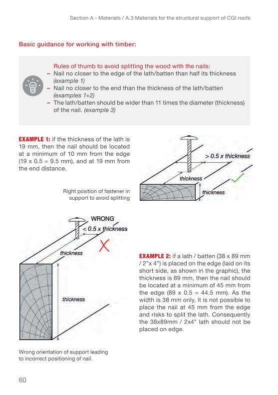
basic guidance for working with timber:
eXAmPle 1: if the thickness of the lath is 19 mm, then the nail should be located at a minimum of 10 mm from the edge (19 x 0.5 = 9.5 mm), and at 19 mm from the end distance.
eXAmPle 2: if a lath / batten (38 x 89 mm / 2”x 4”) is placed on the edge (laid on its short side, as shown in the graphic), the thickness is 89 mm, then the nail should be located at a minimum of 45 mm from the edge (89 x 0.5 = 44.5 mm). As the width is 38 mm only, it is not possible to place the nail at 45 mm from the edge and risks to split the lath. Consequently the 38x89mm / 2x4” lath should not be placed on edge.
Rules of thumb to avoid splitting the wood with the nails:– Nail no closer to the edge of the lath/batten than half its thickness (example 1)– Nail no closer to the end than the thickness of the lath/batten (examples 1+2)– The lath/batten should be wider than 11 times the diameter (thickness) of the nail. (example 3)
Right position of fastener in support to avoid splitting
Wrong orientation of support leading to incorrect positioning of nail.

61
Section A - Materials / A.3 Materials for the structural support of CGI roofs
eXAmPle 3: if the diameter of the roofing nail is 3.76 mm (common diameter), then the lath should be at least 41.4 mm wide (11 x 3.76 = 41.4 mm)
eXAmPle 4: if the diameter of the nail is 4.11 mm, then the penetration depth into the rafter should be at least 50 mm (12 x 4.11 = 50 mm). If the lath is 38 mm thick, then the nail should be at least 88 mm long (50 + 38 = 88 mm) ▹ 3-½” or 4’’ nail.
If nails need to be very long (over 100mm or 4”) and it becomes too difficult to nail laths/battens to a rafter placed on edge, hurricane strap can be used to connect the lath/batten to the rafter (More information on hurricane straps in Chapter A 5. Hurricane straps/ties.)
To fasten well the laths to the rafters, and CGI sheets to the laths, the penetration depth of the nail into the support should be minimum 12 times the diameter of the nail, which means that the nails need to be quite long. (example 4)
width of support based on diameter of the nail
Penetration depth of fastener based on diameter of the nail

62
Section A - Materials / A.3 Materials for the structural support of CGI roofs
A.3.2. coconut wood (coco lumber)
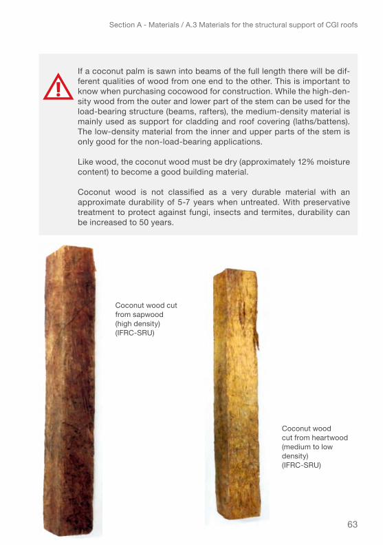
The coconut wood is also called ‘cocowood’, coconut timber and coconut lumber.As the coconut palm is not a tree but a fern, the wood has different properties than wood from trees and cannot be not classified as hardwood or softwood. Within one palm tree there are various densities and strengths depending on the cut in the coco-nut trunk.
In trees the heartwood (central and “dead” part of the tree) is the most densest and hardest the and the sapwood (the outer app 2-10cm “living” part of the tree, of the trunk) is softer throughout the whole length of the tree. For palms it is almost inverse, the inner part of the stem is soft, while the outer part is hard, as shown in the draw-ing. This is just the opposite as for trees. The harder sapwood is usually darker (dark red or brown) than the softer heartwood, which is usually a light shade of brown. Furthermore the bottom meters of a palm are the hardest while the density and hard-ness decreases the further up the stem.
Practical tips to increase the withdrawal resistance for thin laths/ battens – solution mainly for repairs:
When the laths /battens are thin (e.g. 1”x3”), it is possible to increase the withdrawal or pull-out resistance resistance by using roofing nails longer than the thickness of the lath, pierce through the lath/batten and then bend the nails against the lath.
This practice increases the pull out resistance significantly but also has some disadvantages:– As the roofing nail goes through the lath/batten, the risk of leakage is increased, so it is imperative to properly place a rubber washer under the head of the roofing nail.– Since this practice increases the withdrawal strength, it is necessary to ensure that the roofing nail heads do not puncture the CGI sheet under the wind pressure. To do this, you either have a CGI sheet of sufficient thickness (26 gauge) or place a wide sealing washer beneath the fastener head to increase the puncture resistance of the CGI sheet.– Bending each nail is significantly more labour-intense. Nails that are not bent but left with point sticking out present a risk for injury.
63
Section A - Materials / A.3 Materials for the structural support of CGI roofs
If a coconut palm is sawn into beams of the full length there will be dif-ferent qualities of wood from one end to the other. This is important to know when purchasing cocowood for construction. While the high-den-sity wood from the outer and lower part of the stem can be used for the load-bearing structure (beams, rafters), the medium-density material is mainly used as support for cladding and roof covering (laths/battens). The low-density material from the inner and upper parts of the stem is only good for the non-load-bearing applications.
Like wood, the coconut wood must be dry (approximately 12% moisture content) to become a good building material.
Coconut wood is not classified as a very durable material with an approximate durability of 5-7 years when untreated. With preservative treatment to protect against fungi, insects and termites, durability can be increased to 50 years.
Coconut wood cut from sapwood (high density) (ifRC-SRu)
Coconut wood cut from heartwood (medium to low density) (ifRC-SRu)

64
Section A - Materials / A.3 Materials for the structural support of CGI roofs
The table (11) below provides more details on the possible applications.
Table 11 – Use of coconut wood depending on its density
CoConut wood
denSity (kg / m3) ReCoMMended uSe *
High-density • > 600 kg/m3
• Load-bearing structural elements such as posts (solid round form), trusses, rafters, purlins, laths/battens, secondary beams, frames for windows and doors, as well as flooring and floor joists.
Medium-density • 400 – 600 kg/m3 • Exterior walls and studs. It can also be used as roof shingle.
Low-density • < 400 kg/m3 • Non-load-bearing applications, such as interior wall panelling and ceilings.
* Source: Asia Pacific Forestry Sector Outlook: Focus on Coconut Wood, Romulo N. Arancon Jr, FAO, 1997
The tests carried out in the SRU Laboratory showed that the medium-density coconut wood had an approximately 20 % lower withdrawal resistance for roofing nails (twisted shank) and roofing screws than the high-density coconut wood.
For use in very cyclone prone areas it is therefore recommended to use laths/battens made of high-density coconut wood or apply extra fasteners (Additional information is provided in the fasteners chapter). However the high-density coco-lumber is much more difficult to cut and nail and therefore usually less appreciated by the roof-carpenters. Cutting hard coconut wood requires the use of a chain saw or an electric saw with a blade made of tungsten carbide tips (the most wear-resistant steel).
Very hard wood is easier to nail if (hard) soap is applied on the nail.

65
Section A - Materials / A.3 Materials for the structural support of CGI roofs
mechanical properties of coconut wood4:
The table 12 next page presents the mechanical properties of coconut wood based on mature trees. It also provides basic information about workability, possible wood treatment, life expectancy and availability.
4 Sources: Asia Pacific Forestry Sector Outlook: Focus on Coconut Wood, Romulo N. Arancon Jr, FAO, 1997Coconut wood - properties and processing facts for coconut ‘wood’, Australian Centre for International Agricultural Research, revised 2010
Philippines: Coco lumber roof strucuture. (IFRC-SRU)

66
Section A - Materials / A.3 Materials for the structural support of CGI roofs
Table 12 – Mechanical properties of coconut wood based on mature trees
CoConut wood VALUES / DESCRIPTION
Species • cocos nucifera
Moisture content • 12%
Density (kg/m3) • 100 – 1020 kg/m3
high density > 600 kg/m3
Modulus of elasticity E (MPa)
• 2,000 – 25,000 high density: 11,400 MPa
Specific gravity G • 0.26 – 0.59
Static bending – modulus of rupture (MPa)
• 28 – 205 MPa high density: 104 MPa
Maximum crushing strength parallel to grain (MPa)
• 19 – 57 MPa high density: 40 MPa
Compression strength per-pendicular to grain (MPa) • 9.0 MPa
Shear strength parallel to grain (MPa) • 2.1 – 17.37 MPa
Shape • Can be highly deformable
Workability • Firm to hard. Need sharp tools, with high wear resistance. Electric saw with a tungsten carbide tips blade, recommended.
Fixings • Roofing nails• Roofing screws
Possible treatment:
Pressure treatment with:• Copper Azole (CA) – arsenic-free preservative• Alkaline Copper Quat (ACQ)• Light Organic Solvent-borne Preservative (LOSP) – LOSP-treated timber is not suitable for in-ground use
Maturity • Around 50 years
Life expectancy4:
Natural durability (without treatment):• 0 – 7 years for use above-ground• 0 – 5 years for use in-groundWith appropriate wood treatment: over 50 years
Availability:
As local resource: ▹ throughout the Tropics• Asia-Pacific region• africa• latin america

67
Section A - Materials / A.3 Materials for the structural support of CGI roofs
Section sizes of coconut lumber / timber
Coconut wood usually comes in the same dimensions as timber.You can use the table for dimensions of timber and the practical guidance under A 3.1.as reference also for coconut wood.
A.3.3. bAmboo
Bamboo is often seen as a material of poor value. However, certain bamboo species show a resistance greater than lumber or coconut wood which means bamboo can be a very strong construction material which has a great value for building wind-resistant structures in certain contexts.
Some species of bamboo such as e.g. guadua are recommended for construction. Always check locally which type of bamboo is used for construction of buildings.
Bamboo is a non-durable material when left untreated. Durability can be greatly increased by preservation with safe, environment-friendly chemicals. Like wood and coconut wood, the bamboo should be dry before being used as building material.
Nepal: Installing CGI on bamboo structure. (IFRC-SRU)

68
Section A - Materials / A.3 Materials for the structural support of CGI roofs
A.3.4. metAl
Metal structures are not very commonly used for shelters but can be an alternative in some contexts especially:
● when metal frame-construction is commonly used or suitable profiles are locally available at low cost
● when local materials are not available in sufficient quality or quantity and it is necessary to import building materials
● when the wind resistance should be very high (shelter built in an area subject to highest category of cyclones)
● for buildings with large-span purlins (schools, hospitals, agricultural or industrial buildings)
The metal purlins are made of structural steel, which is hot-rolled for cold forming. They can be hot-dip gal-vanized or made of stainless steel, depending on the environment corrosion rate.
Typical profiles for metal purlins:● Z profile ▹ size from 100 – 250 mm, thickness from 1 – 5 mm● C profile ▹ size from 30 x 11.5 x 2 mm – 140 x 50 x 3 mm
If the purlins are made of raw steel, it is necessary to avoid direct contact between the raw steel and the CGI sheets by painting the purlins or using distance materials (e.g. pieces of rubber) where purlins and CGI are in direct contact, otherwise, there is a high risk of galvanic corrosion.
Profiles of metal purlin: Z and C
Untreated steel corrodes much faster than CGI sheeting. (IFRC-SRU)

69
Section A - Materials / A.3 Materials for the structural support of CGI roofs
mechanical properties of metal purlins:
The table below indicates the basic mechanical properties of metal purlins, as well as the type of fixings/fasteners to use.
Table 13 – Basic mechanical properties of metal purlins
A.3.5. AdvAntAgeS And diSAdvAntAgeS of eAch tYpe of S upport
Each material used as support structure for CGI sheets presents advantages and disadvantages, depending on factors, such as local availability and acceptance, the use and type of fixings/fasteners, difficulty of implementation, resistance/strength and of course price.
Of the four types of supports materials presented lumber and coconut wood seem to be the most commonly used in humanitarian sheltering with CGI sheets. As for bamboo, it is more widely used with natural types of roof covering, like different kinds of thatch. It can also be used with tarpaulin covering for emergency sheltering. Steel in generally used more for larger types of construction or if resistance needs to be particularly high.
The table 14 next page gives a basic overview that can help to decide the most suit-able support material for a given context and project.
METAL PURLIN REQUIRED VALUES / DESCRIPTION
Material • Hot-dip galvanized steel• Stainless steel• Depending on the environment corrosion rate
Steel • Structural steel S350GD, hot-rolled galvanized steel for cold forming
Tensile strength (MPa) • 420 MPa minimum
Yield strength (MPa) • 350 MPa minimum
Modulus of elasticity E (MPa • Structural steel: 210,000 MPa • Stainless steel: 180,000 MPa
Coating • Minimum zinc coating Z275 (275 g/m2)• Stainless in harsh environments
Fixings • Roofing screws only ▹ Self-piercing screws

70
Section A - Materials / A.3 Materials for the structural support of CGI roofs
Support + AdvAntAgeS – diSAdvAntAgeS
LUMBER / TIMBER(Softwood)
+ high resistance, similar to coconut wood (high density)+ Easy to work with (easy to cut, nail, screw)+ Use of roofing nails or roofing screws
– Usually imported material– Expensive if not locally sourced– Must be treated– Requires thick lath/ batten and long fixings to ensure a good withdrawal resistance
CoConut wood
+ high to medium resistance+ local material+ Less expensive if locally sourced+ Similar resistance as softwoods (pine)+ Use of roofing nails or screws
– Must be treated– Use only mature coconut trees (over 50 years) for construction– Various densities and strengths ▹ necessary to use high density for the structure – Can be difficult to cut and hard to nail– Requires thick lath/ batten and long fixings to ensure a good withdrawal resistance
baMboo (guadua)
+ local material+ Less expensive if locally sourced+ Can be more resistant than lumber and coconut wood for building the shelter frame
– Withdrawal resistance and fixings not confirmed. Not recommended as support for CGI sheets roofs in cyclone prone areas– Necessity to use specific fixings ▹ German wire (roofing nails or screws are not suitable)– Use only mature bamboo that is specific for construction– Must be treated– Requires skilled builders
Metal
+ Very resistant ▹ can be used in high-category cyclone region+ Useful for very large span ▹ usually used for industrial or agricultural buildings
– Usually imported materials– Costly – Needs to be protected against corrosion ▹ use of galvanized or stainless steel depending on the environment– Use of self-piercing roofing screws only– Requires power tools (drill, electric saw, grinder)– Requires skilled builders
Table 14 – Advantages and disadvantages of each type of support

71
Section A - Materials / A.4 Fixings / fasteners and accessoiries
A. 4 fiXingS / fAStenerS And AcceSSoirieSThere are various kind of hooks and screws available in the market depending upon the material and type of purlins on which sheets need to be fixed. This chap-ter presents the most common types of fixings or fasteners and their accessories used to safely fix CGI sheets to a roof structure. Research undertaken on causes of steel building failures worldwide indicate that almost 80% of failures start from the fasteners. Since fasteners, used on cladding and structure together, constitute roughly 6-8% of the entire project cost, builders often have the tendency to neglect this vital aspect of their project.
Usage of recommended accessories leads to enhanced life of roofs and walls. Poor and substandard quality of accessories may adversely affect the superior quality of cladding sheets leading to reduced life. Accessories and the cladding material should have similar life expectancies as that of the main structure and hence crite-ria for selecting the accessories such as Fasteners, Gutters and Flashings must be based on the design life of the structure.
Depending on the support material, different kind of fixings might be needed. The performance of the fixings depends on the type, size, material, penetration depth and number of fixings used. Your choice will depend on what material is locally avail-able, that can provide a good withdrawal resistance in order to ensure secured fix-ings of the CGI sheets.
The fasteners most commonly used to attach the CGI sheets to timber or coconut wood are:
● roofing nails: smooth-shank● roofing nails: twisted shank● roofing screws
Bamboo and metal purlins require special types of fixings.
G.I. Hook Bolt should be used for fixing sheets to angle iron purlins. G.I. Crank Bolt should be used for fixing sheets to channels or rectangular/square tubes purlins
Standards (at least ASTM and European) no longer allow using roofing nails, with smooth or twisted shanks, to fasten the CGI sheets but promote screws or roofing lag screws. However roofing nails are still the most commonly used in countries of the south where humanitarian shelter operations typically take place and are therefore presented in this manual. It is interesting to note, that roofing nails with smooth-shanks are already no longer available in the Caribbean region, since their performance is considered too poor.
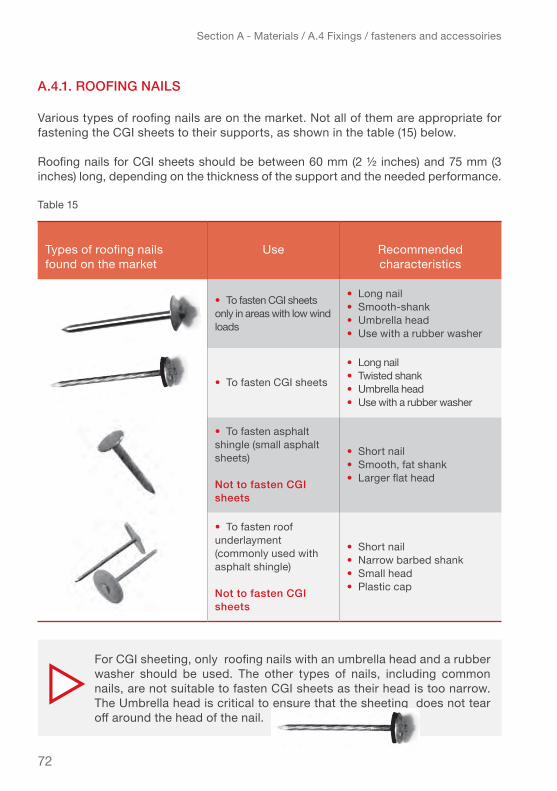
72
Section A - Materials / A.4 Fixings / fasteners and accessoiries
A.4.1. roofing nAilS
Various types of roofing nails are on the market. Not all of them are appropriate for fastening the CGI sheets to their supports, as shown in the table (15) below.
Roofing nails for CGI sheets should be between 60 mm (2 ½ inches) and 75 mm (3 inches) long, depending on the thickness of the support and the needed performance.
Table 15
Types of roofing nails found on the market
use Recommended characteristics
• to fasten Cgi sheets only in areas with low wind loads
• Long nail• Smooth-shank• umbrella head• use with a rubber washer
• to fasten Cgi sheets
• Long nail• Twisted shank • umbrella head• use with a rubber washer
• to fasten asphalt shingle (small asphalt sheets)
not to fasten cgi sheets
• Short nail• Smooth, fat shank• Larger flat head
• to fasten roof underlayment (commonly used with asphalt shingle)
not to fasten cgi sheets
• Short nail• Narrow barbed shank• Small head• Plastic cap
For CGI sheeting, only roofing nails with an umbrella head and a rubber washer should be used. The other types of nails, including common nails, are not suitable to fasten CGI sheets as their head is too narrow. The Umbrella head is critical to ensure that the sheeting does not tear off around the head of the nail.
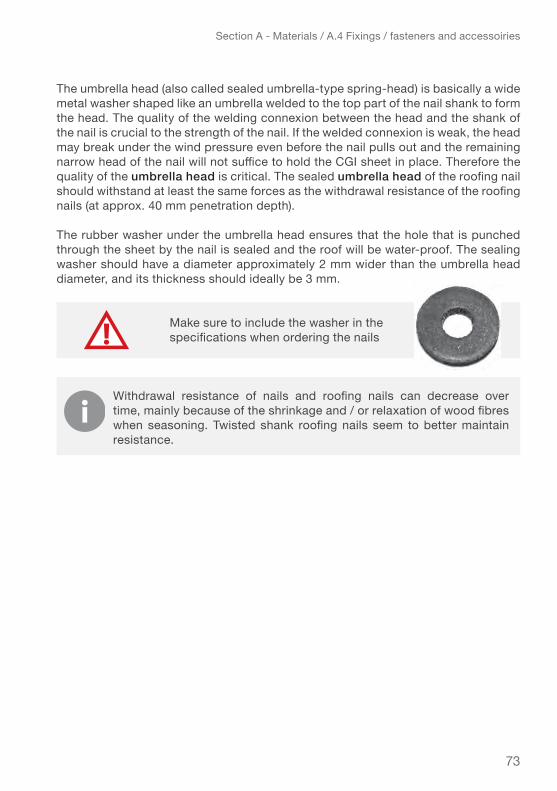
73
Section A - Materials / A.4 Fixings / fasteners and accessoiries
The umbrella head (also called sealed umbrella-type spring-head) is basically a wide metal washer shaped like an umbrella welded to the top part of the nail shank to form the head. The quality of the welding connexion between the head and the shank of the nail is crucial to the strength of the nail. If the welded connexion is weak, the head may break under the wind pressure even before the nail pulls out and the remaining narrow head of the nail will not suffice to hold the CGI sheet in place. Therefore the quality of the umbrella head is critical. The sealed umbrella head of the roofing nail should withstand at least the same forces as the withdrawal resistance of the roofing nails (at approx. 40 mm penetration depth).
the rubber washer under the umbrella head ensures that the hole that is punched through the sheet by the nail is sealed and the roof will be water-proof. The sealing washer should have a diameter approximately 2 mm wider than the umbrella head diameter, and its thickness should ideally be 3 mm.
Make sure to include the washer in the specifications when ordering the nails
Withdrawal resistance of nails and roofing nails can decrease over time, mainly because of the shrinkage and / or relaxation of wood fibres when seasoning. Twisted shank roofing nails seem to better maintain resistance.

74
Section A - Materials / A.4 Fixings / fasteners and accessoiries
eXAmple technicAl SpecificAtionS of roofing nAilS for cgi SheetS
The IFRC Emergency Items Catalogue (EIC as of 2016) proposes one type of roofing nail (two available lengths) with the technical specifications described in the table (16) below.
Table 16 – Roofing nail technical specifications from EIC
DESCRIPTION
Roofing nails with sealed umbrella-type spring-head, twisted shank and rubber washer
Type • Galvanized steel nail, made of polished low-carbon steel, cold processed
Head • Sealed umbrella-type spring-head (commonly called umbrella head)
Shank • Helically threaded or spiral rolled (commonly called twisted)
Diameter of the shank • 3.76 mm
Length of the nail • 60 mm (2 ½ inches) – ideal for a 40mm-thick lath/batten• 75 mm (3 inches) – recommended for a thicker lath/batten
Diameter of the head (umbrella head) • Minimum 20 mm
Rubber washer• Diameter: 22 mm ▹ diameter of nail head + 2 mm recommended (i.e. 22 mm)• Thickness: 2 mm minimum – 3 mm recommended
Metal • Hot-dip galvanized steel (electro-galvanized steel should not be used in treated wood and corrosive environments)
Corrosion treatment
• Zinc coating: minimum required 275 g/m2 (20µm/side)• Coating mass: 350 g/m2 recommended for environments C1–C4• Coating mass: 450 g/m2 recommended for environments C5 + CX
Tensile strength • Minimum 600 MPa
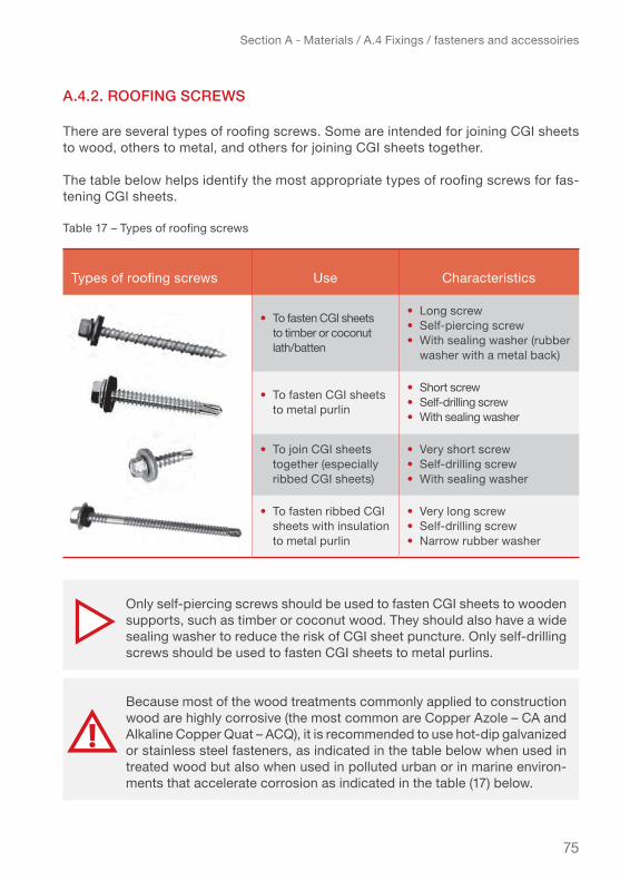
75
Section A - Materials / A.4 Fixings / fasteners and accessoiries
A.4.2. roofing ScrewS
There are several types of roofing screws. Some are intended for joining CGI sheets to wood, others to metal, and others for joining CGI sheets together.
The table below helps identify the most appropriate types of roofing screws for fas-tening CGI sheets.
Table 17 – Types of roofing screws
Types of roofing screws use Characteristics
• to fasten Cgi sheets to timber or coconut lath/batten
• Long screw• Self-piercing screw• With sealing washer (rubber washer with a metal back)
• to fasten Cgi sheets to metal purlin
• Short screw• Self-drilling screw• With sealing washer
• To join CGI sheets together (especially ribbed Cgi sheets)
• Very short screw• Self-drilling screw• With sealing washer
• to fasten ribbed Cgi sheets with insulation to metal purlin
• Very long screw• Self-drilling screw• narrow rubber washer
Only self-piercing screws should be used to fasten CGI sheets to wooden supports, such as timber or coconut wood. They should also have a wide sealing washer to reduce the risk of CGI sheet puncture. Only self-drilling screws should be used to fasten CGI sheets to metal purlins.
Because most of the wood treatments commonly applied to construction wood are highly corrosive (the most common are Copper Azole – CA and Alkaline Copper Quat – ACQ), it is recommended to use hot-dip galvanized or stainless steel fasteners, as indicated in the table below when used in treated wood but also when used in polluted urban or in marine environ-ments that accelerate corrosion as indicated in the table (17) below.
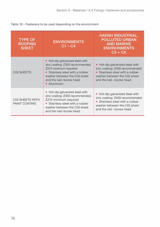
76
Section A - Materials / A.4 Fixings / fasteners and accessoiries
Table 18 – Fasteners to be used depending on the environment
tYpe of roofing
Sheet environmentS
c1 – c4
hArSh induStriAl, polluted urbAn
And mArine environmentS
c5 + cX
Cgi SHeetS
• Hot-dip galvanized steel with zinc coating: Z350 recommended, Z275 minimum required• Stainless steel with a rubber washer between the Cgi sheet and the nail-/screw head• aluminium
• Hot-dip galvanized steel with zinc coating: Z450 recommended• Stainless steel with a rubber washer between the Cgi sheet and the nail -/screw head
Cgi SHeetS witH PAINT COATING
• Hot-dip galvanized steel with zinc coating: Z350 recommended, Z275 minimum required• Stainless steel with a rubber washer between the Cgi sheet and the nail-/screw head
• Hot-dip galvanized steel with zinc coating: Z450 recommended• Stainless steel with a rubber washer between the Cgi sheet and the nail -/screw head
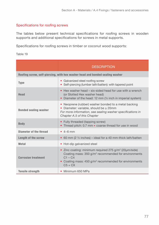
77
Section A - Materials / A.4 Fixings / fasteners and accessoiries
Specifications for roofing screws
The tables below present technical specifications for roofing screws in wooden supports and additional specifications for screws in metal supports.
Specifications for roofing screws in timber or coconut wood supports:
Table 19
DESCRIPTION
Roofing screw, self-piercing, with hex washer head and bonded sealing washer
Type • Galvanized steel roofing screw• Self-piercing (lumber lath/batten): with tapered point
Head • Hex washer head – six-sided head for use with a wrench (or Slotted Hex washer head)• Diameter of the head: 12 mm (½ inch in imperial system)
Bonded sealing washer
• Neoprene (rubber) washer bonded to a metal backing• Diameter: variable, should be ≥ 20mmFor more information, see sealing washer specifications in Chapter A.5 of this Chapter
Body • Fully threaded (tapping screw)• Thread pitch: 0.7 mm ▹ coarse thread for use in wood
Diameter of the thread • 4–6 mm
Length of the screw • 60 mm (2 ½ inches) – ideal for a 40 mm-thick lath/batten
Metal • Hot-dip galvanized steel
Corrosion treatment
• Zinc coating: minimum required 275 g/m2 (20µm/side) Coating mass: 350 g/m2 recommended for environments C1 – C4• Coating mass: 450 g/m2 recommended for environments C5 + CX
Tensile strength • Minimum 650 MPa

78
Section A - Materials / A.4 Fixings / fasteners and accessoiries
Specifications for roofing screws in metal supports:
The specifications are identical to the ones above except for the characteristics of the type Head and Body as described in the table below.
Table 20
DESCRIPTION
Roofing screw, self-drilling, with hex washer head and bonded sealing washer
Type • Galvanized steel roofing screw• Self-drilling (metal lath/batten or purlin): with a drill bit point
Head • Hex washer head – six-sided head for use with a wrench• Diameter of the hex head: 12 mm (½ inch in imperial system)
Body • Fully threaded (tapping screw)• Thread pitch: narrow thread for use in metal
Nepal: J-hooks used on round section steel support. (IFRC-SRU)

79
Section A - Materials / A.4 Fixings / fasteners and accessoiries
A.4.3. pArticulAr fiXingS for metAl And bAmboo
hooks and bolts
Galvanized J or L hooks fixed with bolts and nuts can provide strong fixings for CGI sheets to bamboo or other round section supports as well as to metal purlins.Depending on the required strength they can be M6 (diameter 6 mm) or M8 (diameter 8 mm).
The length should be equal to the height of the Purlin + 76 mm for single sheet fix-ing and height of Purlin + 89 mm for two over lapping sheets. Hooks, bolts and nuts should be of the same quality of galvanization (hot dipped) as the used CGI sheets.
Some basic advice for fixing bolts:● Holes for hooks bolts should be drilled (not punched) through the CGI in the crest
of corrugation, not in the trough (as mentioned on the drawing page 22).● Where the sheets are overlapping, the overlap should be minimum 15 cm and the
bolt should be fixed through the second overlapping corrugation (not in the first).● Use with rubber washer of 25 mm in diameter and 3 mm thick and flat washer of
25 mm in diameter (if it is a round washer) and 1.60 mm thick to ensure proper sealing where the CGI has been punctured.
A lot of different types of hooks exist, check what is available locally and confirm necessary performance (number and necessary spacing) with calculations to identify the adequate choice!
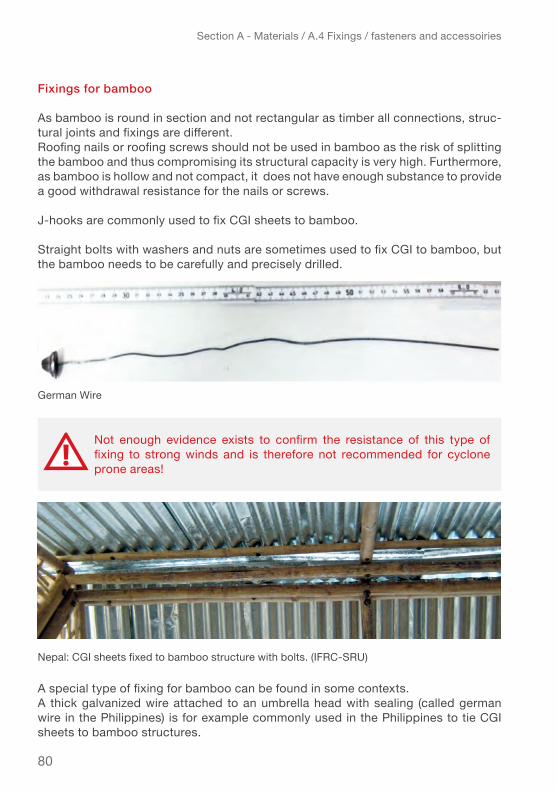
80
Section A - Materials / A.4 Fixings / fasteners and accessoiries
fixings for bamboo
As bamboo is round in section and not rectangular as timber all connections, struc-tural joints and fixings are different.Roofing nails or roofing screws should not be used in bamboo as the risk of splitting the bamboo and thus compromising its structural capacity is very high. Furthermore, as bamboo is hollow and not compact, it does not have enough substance to provide a good withdrawal resistance for the nails or screws.
J-hooks are commonly used to fix CGI sheets to bamboo.
Straight bolts with washers and nuts are sometimes used to fix CGI to bamboo, but the bamboo needs to be carefully and precisely drilled.
A special type of fixing for bamboo can be found in some contexts.A thick galvanized wire attached to an umbrella head with sealing (called german wire in the Philippines) is for example commonly used in the Philippines to tie CGI sheets to bamboo structures.
Not enough evidence exists to confirm the resistance of this type of fixing to strong winds and is therefore not recommended for cyclone prone areas!
german wire
Nepal: CGI sheets fixed to bamboo structure with bolts. (IFRC-SRU)

81
Section A - Materials / A.4 Fixings / fasteners and accessoiries
A.4.4. SeAling wASherS
The purpose of sealing washers is to keep the CGI sheets from tearing off around the nails while ensuring the waterproofing of the roof where the sheets are punctured by the roofing nails or screws.
Sealing washers are rubber washer with a metal back. They are composed of a rigid part made of hot-dip galvanized steel (Z275), stainless steel or aluminium, and a flex-ible elastomer section (rubber). They are usually round, but they can also be oval or square.
In order to be effective, the diameter of the sealing washers should not be less than 20 mm. The thickness of the galvanized steel or stainless-steel washer should be 0.75 mm minimum, while the aluminium one should be 1 mm minimum. The thickness of the rubber washer should be 2 mm (minimum) – 3 mm (recommended).
In the table (21) below are some examples of maximal puncture resistance (in N) of
No tests have been conducted to verify the resistance of the German wire. It is not guaranteed that the resistance of german wire equals that of a roofing nail. It is strongly recommended to conduct resistance tests before use and/or look for more information locally when planning to use this fixing.
in order to get optimum performance of all elements possibly, the withdrawal resistance of the fasteners should be more or less equal to the maximal puncture resistance of the cgi sheet.
when puncture resistance of the sheets is lower than withdrawal resistance of the fixings, (because the sheets are too thin and/or the fix-ings’ heads too small), the sheets will tear off around the fixing.
If the withdrawal resistance of the fixings is lower than the puncture resistance of the sheeting, the fixings will be pulled out by the sheet.
washers increase the puncture resistance of the sheeting and can help to strike the balance between cgi thickness/puncture resistances, the withdrawal resistance of the fixings and in some cases even, allow reducing the number of fasteners.
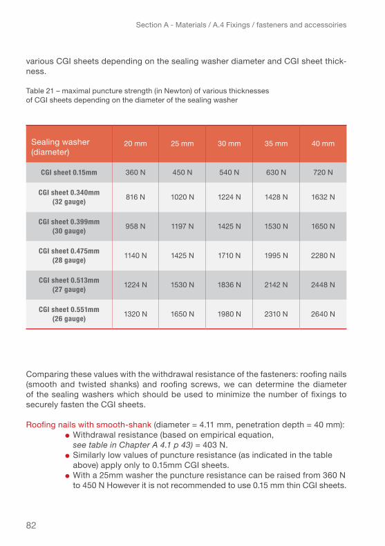
82
Section A - Materials / A.4 Fixings / fasteners and accessoiries
various CGI sheets depending on the sealing washer diameter and CGI sheet thick-ness.
Table 21 – maximal puncture strength (in Newton) of various thicknesses of CGI sheets depending on the diameter of the sealing washer
Comparing these values with the withdrawal resistance of the fasteners: roofing nails (smooth and twisted shanks) and roofing screws, we can determine the diameter of the sealing washers which should be used to minimize the number of fixings to securely fasten the CGI sheets.
Roofing nails with smooth-shank (diameter = 4.11 mm, penetration depth = 40 mm):● Withdrawal resistance (based on empirical equation, see table in Chapter A 4.1 p 43) = 403 N.● Similarly low values of puncture resistance (as indicated in the table above) apply only to 0.15mm CGI sheets. ● With a 25mm washer the puncture resistance can be raised from 360 N to 450 N However it is not recommended to use 0.15 mm thin CGI sheets.
Sealing washer (diameter)
20 mm 25 mm 30 mm 35 mm 40 mm
CGI sheet 0.15mm 360 N 450 N 540 N 630 N 720 N
CGI sheet 0.340mm(32 gauge) 816 N 1020 N 1224 N 1428 N 1632 N
CGI sheet 0.399mm (30 gauge) 958 N 1197 N 1425 N 1530 N 1650 N
CGI sheet 0.475mm(28 gauge) 1140 N 1425 N 1710 N 1995 N 2280 N
CGI sheet 0.513mm(27 gauge) 1224 N 1530 N 1836 N 2142 N 2448 N
CGI sheet 0.551mm(26 gauge) 1320 N 1650 N 1980 N 2310 N 2640 N

83
Section A - Materials / A.4 Fixings / fasteners and accessoiries
Roofing nails with twisted shank (diameter = 3.76 mm, penetration depth = 40mm):● Withdrawal resistance (based on empirical equation, see table in Chapter A 4.1 p44): = 925 N. ● Use of a sealing washer is not required for CGI sheet thickness: 0.399–0.551 mm (30–26 gauge). ● For CGI sheet thickness 0.34 mm (32 gauge) a 25 mm-diameter sealing washer can increase the puncture resistance from 816 N (lower than the nail’s withdrawal resistance of 924 N) to 1020 N (higher than the nail’s withdrawal resistance of 924 N), which is higher than puncture resistance of 0.399 mm (30 gauge) sheeting with roofing nails with 20 mm umbrella head. Although 0.34mm (32 gauge) thin CGI sheet is generally not recommended, it can be checked for a particular case by using the roof estimate form in Annex 5 (Excel spreadsheet, Annex 7)
Roofing screws (diameter=4.17 mm, penetration depth=40mm): withdrawal resistance (based on empirical equation): = 1519 N
● The use of screws does not make any sense for CGI of 0.15 mm as puncture resistance is far lower than withdrawal resistance of roofing screws even when using large washers. ● A 40 mm-diameter sealing washer will bring the puncture resistance of the 0.34 mm (32 gauge) CGI sheet up to 1632 N to be slightly higher than the withdrawal resistance of the screw. ● Similarly a 35 mm-diameter sealing washer should be used for CGI sheet thickness 0.399 mm (30 gauge), a 30 mm-diameter sealing washer for CGI sheet thickness 0.475 mm (28 gauge) etc.
Roofing screws usually come with a bonded 15mm-diameter sealing washer. However, the 15mm-diameter washer is not wide enough to allow a good puncture resistance for CGI sheets of less than 0.551mm (26 gauge) thickness. The puncture resistance for the screws is more or less equivalent to the withdrawal strength of a twisted-shank roofing nail. This means the resistance to uplift forces will be equivalent but at a higher cost, because the screws are more costly and will not be able to perform at their highest capacity. Consequently, it only makes sense to use roofing screws in combination with a wider sealing washer or a thicker CGI sheet, in cases where maximum resistance to very high wind loads is required. In most cases, twisted roofing nails are the more cost-effective alternative.
If the diameter of the roofing nail (twisted-shank) is larger than 3.76 mm and roofing screw is larger than 4.11 mm (as the examples used above), then the withdrawal resistance will increase. Consequently, the sealing washer diameter will need to increase as well. The opposite is also true.

84
Section A - Materials / A.5. – Performance testing
A.5. performAnce teSting of fiXingS And SupportS conducted bY ifrc-Sru
In summer 2014 IFRC-SRU conducted comparative testing on different fixings, support materials and CGI qualities. A series of tests were conducted to provide evidence for:
● The “ideal” section size for the support ● The “optimum” penetration depth● Compare the pull-out resistance of different types of fixings to identify the “strongest” fastener. ● Compare the different support materials (pine and two qualities of coconut wood) pull-out resistance to identify the most robust support.
The following fixings and support materials were tested:
● Smooth-shank and twisted shank roofing nails and roofing screws (as procured in the Philippines).● Pine timber as commonly know reference, “high-density” coconut wood (also called “red” or “hard” coconut wood with average density over 600 kg /m3) and “medium-density” coco-nut wood (also called “white” or “soft" coconut wood with average density between 400-600 kg /m3) (for more information on coconut wood see chapter A 3.2.).
Samar, Philippines: Test set-up for pull-out resistance in different
sections but same penetration depth. (IFRC-SRU)

85
Section A - Materials / A.5. – Performance testing
For the testing the different fasteners where fixed to the support and then pulled out (using a pulley and steadily applying force) while measuring the resistance until “ pulling out” failure with a dynamometer.
for each parameter the tests were repeated at least three times with the same configuration to ensure accuracy (for more information on test conducted and results, see http://ifrc-sru.org/wp-content/uploads/2014/09/Daniel-Ledesma-Field-testing-on-CGI-roofing-fixings.pdf.
Most of the findings from the tests confirm the empirical equations (engineering cal-culations based on standard values).
the “ideal” section:
● The test clearly confirms that a 2” x 3” (38 x 64 mm) lath laid flat provides the best support that is, the highest withdrawal resistance for the fastener (average recorded loading capacity 186 kg in red coconut wood). Interestingly the same 2”x 3” lath laid on edge with the same penetration depth (approx. 40 mm) of the fastener only provided 75% of the performance of lath laid flat (average recorded loading capacity 139 kg in red coconut wood).
● 50 x 50 mm laths/battens (equivalent of a 2”x2”) are not wide enough to resist splitting by the roofing nail and securely fasten the CGI sheets. Either use thinner nails, if the load calculations allow, or for better performance wider laths e.g. 50 x 63 mm or 50 x 76 (equivalent of a 2”x 3”) flat.
● laths of less than 2” (38 mm) thickness do not allow for sufficient penetration depth to provide full performance of the fastener. It is possible to use laths/battens between 1” (19 mm) and 2” thickness for fixing the CGI sheets, however, it will take 2 times more fasteners to hold the CGI sheet in place when subject to strong winds, than for 2” laths. Furthermore the 1” thick laths will barely support anybody walking on the roof during construction, repairs or maintenance. ▹ Gains in practicality, work time and safety and reduction of fasteners will most
probably outweigh potential saving made with thinner laths.▹ the “ideal” support uses the section “laid flat” with the thickness approx.
2/3 of the width. thickness should be a minimum 2” or 50 mm and width should be larger than 2” or 50 mm.
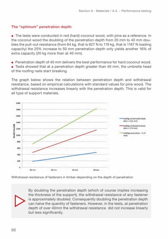
86
Section A - Materials / A.5. – Performance testing
the “optimum” penetration depth:
● The tests were conducted in red (hard) coconut wood, with pine as a reference. In the coconut wood the doubling of the penetration depth from 20 mm to 40 mm dou-bles the pull-out resistance (from 64 kg, that is 627 N to 119 kg, that is 1167 N loading capacity) the 25% increase to 50 mm penetration depth only yields another 16% of extra capacity (20 kg more than at 40 mm).
● Penetration depth of 40 mm delivers the best performance for hard coconut wood.● Tests showed that at a penetration depth greater than 40 mm, the umbrella head of the roofing nails start breaking.
The graph below shows the relation between penetration depth and withdrawal resistance, based on empirical calculations with standard values for pine wood. The withdrawal resistance increases linearly with the penetration depth. This is valid for all type of support materials.
By doubling the penetration depth (which of course implies increasing the thickness of the support), the withdrawal resistance of any fastener is approximately doubled. Consequently doubling the penetration depth can halve the quantity of fasteners. However, in the tests, at penetration depth of over 40mm the withdrawal resistance did not increase linearly but less significantly.
Withdrawal resistance of fasteners in timber depending on the depth of penetration

87
Section A - Materials / A.5. – Performance testing
the “strongest” fastener:
The graph below shows the values calculated with the empirical equations5 (shown as columns of light colours) for the three common fasteners studied, suggest that pull out resistance about doubles from smooth-shank to twisted shank nail’s and again to roofing screws. Interestingly the IFRC-SRU tests (columns of dark colours) conducted on the same three types of fasteners in three types of support show quite some variations.
5 Source: empirical equations for fasteners found in the Wood handbook, chapter 7, Fastening
Optimum penetration depth is min 40 mm for all wood supports (of course metal and bamboo are different). Increasing the penetration depth also implies increasing the resistance and quality of the fasteners in order to prevent their failure. Over 50 mm penetration depth does not sufficiently increase the performance to justify the necessary thicker laths.
3500
3000
2500
2000
1500
1000
500
0Max
imum
trac
tion
forc
e (N
)
high-density coconut wood
medium-density coconut wood
pine
Withdrawal resistance of three types of fasteners in three different supports compared to values based on empirical equations
● smooth-shank roofing nail (value based on SRu tests)● smooth-shank roofing nail (based on empirical equa-tion)● twisted shank roofing nail (value based on SRu tests)● twisted-shank roofing nail (based on empirical equa-tion)● roofing screw (value based on SRu tests)● roofing screw (based on empirical equation)

88
Section A - Materials / A.5. – Performance testing
● The empirically derived relationships indicate the twisted nail provides the double performance of the smooth-shank nail, and the roofing screw double the perform-ance of the twisted shank nail for all support types studied. The IFRC-SRU test results show rather varied performance in the different wood types:
● The smooth-shank roofing nail performed considerably (more than 60%) better in the tests than suggested in the empirical equations. Especially in the hard coconut wood the performance was five times higher than expected. Also for the two “softer” woods, pine and white coconut wood, the perform-ance is respectively 60% and 90% higher than suggested by the equations.
● the twisted-shank roofing nail showed double the expected performance in hard coconut wood but underperformed by about 25% in soft coconut wood only equalling the performance as the smooth smooth-shank nail whereas it was expected to perform twice as well! In pine the performance just about reaches the expected results but is still some 40% higher than of the smooth-shank nail.
● the roofing screws perform approx. 75% higher in hard coconut wood and give twice the performance in pine, however roofing screws do not reach the expected performance in soft coconut wood.
The evidence from the tests suggests that the smooth-shank roofing nails performance is generally underestimated but remains low. Twisted-shank roofing nails seem to perform better in hard wood than in soft wood. Clearly the roofing screws provide the overall highest performance.
To draw clear conclusions and give recommendations, whether e.g. number of roofing screws can be reduced or the smooth-shank roofing nails can provide sufficient performance for safer roof fixings even in contexts with considerable wind-loads, more detailed testing and studies are needed, especially looking at performance under irregular stresses and over time. It would be interesting to further explore the performance of smooth-shank nails compared to twisted -shank. For example to confirm if the performance of the twisted-shank nail, that comes at approx. 20% higher cost than the smooth-shank nail, only performs at approx. 19% higher than the smooth-shank nail in hard coconut wood, as suggested by the evidence from the tests.

89
Section A - Materials / A.5. – Performance testing
the most robust support
● in hard coconut wood the tested performance of all fasteners is considerably higher than suggested by the empirical equations that are used as reference. For the smooth-shank nails almost 5 times higher, the twisted shank nail almost dou-ble and the roofing screw still some 75% higher than expected. The performance is by approx. 19% higher from smooth-shank nail to twisted-shank nail and from twisted-shank nail to roofing screw.
● the performance in soft coconut wood according to the tests is still approx. 90% better than suggested by the empirical calculations for the smooth-shank nail how-ever almost 30% less than expected for the twisted nail as well as for the screw.
● in pine wood the variations with regard to the equations are the highest, approx. 60% better for the smooth nail, some 8% below the expected for the twisted nail and double for the screw.
(See also graphs on p. 87)
comparative overview of roofing nails and roofing screws based on evidence from ifrc–Sru testing
The comparison parameters include: withdrawal resistance, resistance to puncture, availability on the market, ease of use, and cost.
The table (22) next page should help you identify which type of fasteners to choose
According to the tests, hard (high-density) coconut wood can be considered a good shelter construction material. However quality needs to be confirmed carefully to ensure the proper performance.
The roof calculation form in Annex 5 (Excel spreadsheet, Annex 7) is based on the empirical equations. As the tests show, the calculations are on the safe side, except for the soft coconut wood where calculations assume better performance than the tests show. Therefore medium-density (soft) coconut wood is not recommended for structural construction.
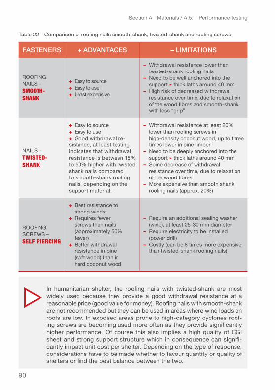
90
Section A - Materials / A.5. – Performance testing
Table 22 – Comparison of roofing nails smooth-shank, twisted-shank and roofing screws
fAStenerS + AdvAntAgeS – limitAtionS
Roofing nailS – smooth- shAnk
+ Easy to source+ Easy to use+ Least expensive
– withdrawal resistance lower than twisted-shank roofing nails– need to be well anchored into the support ▹ thick laths around 40 mm– High risk of decreased withdrawal resistance over time, due to relaxation of the wood fibres and smooth-shank with less “grip”
nailS – twisteD- shAnk
+ Easy to source+ Easy to use+ good withdrawal re-sistance, at least testing indicates that withdrawal resistance is b etween 15% to 50% higher with twisted shank nails compared to smooth-shank roofing nails, depending on the support material.
– Withdrawal resistance at least 20% lower than roofing screws in high-density coconut wood, up to three times lower in pine timber– Need to be deeply anchored into the support ▹ thick laths around 40 mm– Some decrease of withdrawal resistance over time, due to relaxation of the wood fibres– More expensive than smooth shank roofing nails (approx. 20%)
Roofing SCRewS – self PieRcing
+ best resistance to strong winds + Requires fewer screws than nails ( approximately 50% fewer)+ better withdrawal resistance in pine (soft wood) than in hard coconut wood
– Require an additional sealing washer (wide), at least 25-30 mm diameter– Require electricity to be installed (power drill)– Costly (can be 8 times more expensive than twisted-shank roofing nails)
In humanitarian shelter, the roofing nails with twisted-shank are most widely used because they provide a good withdrawal resistance at a reasonable price (good value for money). Roofing nails with smooth-shank are not recommended but they can be used in areas where wind loads on roofs are low. In exposed areas prone to high-category cyclones roof-ing screws are becoming used more often as they provide significantly higher performance. Of course this also implies a high quality of CGI sheet and strong support structure which in consequence can signifi-cantly impact unit cost per shelter. Depending on the type of response, considerations have to be made whether to favour quantity or quality of shelters or find the best balance between the two.

91
Section A - Materials / A.6. Hurricane straps / ties
for your project.A.6. hurricAne StrApS / tieShurricane straps/ ties are metal connectors used to reinforce all types of con-nections, from foundations to the roof, to make a structure resistant to very strong winds. Hurricane straps come in various shapes each fit for a specific purpose.
Installing hurricane straps to strengthen the roof will allow the roof to resist uplift forces. However, if the entire structure is not properly designed and / or reinforced - from the foundations to the roof - to withstand wind pressure then other parts of the shelter/house will fail before the roof. It is imperative to verify that the entire structure is built to resist wind pressure and other usual loads. Most joints and connections, not only of the roof structure, can be efficiently reinforced using hurricane straps.
As this is a very broad topic which would merit a separate manual this chapter only gives a general overview of the most common types of hurricane straps used to hold in place the roof frame when under high wind pressure:
● Coiled straps ● Hurricane straps of various shapes
These are used to strengthen the connection:
● 1. Between the battens and rafters, they need to resist vertical forces.
● 2. Between the rafters and wall plates need to resist vertical and horizontal forces.This manual does not give guidance on how to determine precisely which type of hurricane straps to use. However if you already have a shelter design you can use the Roof Estimate Form (Excel spreadsheet in Annex 7) to calculate the forces that the different straps have to resist. Then you can consult a supplier catalogue, and choose from the models that resist the forces.
Hurricane straps are made of hot-dip galvanized steel or stainless steel. Which material is more adequate to use depends on the environment they are exposed to (See Section A under 2.3 service life). The zinc coating mass used for hurricane straps is usually between 350 – 450 g/m2 (Z350 or Z450). The minimum acceptable
Hurricane straps can resist either vertical forces (tensile loads) or vertical and horizontal forces (tensile and shear loads). Be careful to choose the right kind of strap for the respective type of connection!
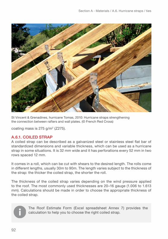
92
Section A - Materials / A.6. Hurricane straps / ties
coating mass is 275 g/m2 (Z275).
A.6.1. coiled StrApA coiled strap can be described as a galvanized steel or stainless steel flat bar of standardized dimensions and variable thickness, which can be used as a hurricane strap in some situations. It is 32 mm wide and it has perforations every 52 mm in two rows spaced 12 mm.
It comes in a roll, which can be cut with shears to the desired length. The rolls come in different lengths, usually 30m to 90m. The length varies subject to the thickness of the strap: the thicker the coiled strap, the shorter the roll.
The thickness of the coiled strap varies depending on the wind pressure applied to the roof. The most commonly used thicknesses are 20–16 gauge (1.006 to 1.613 mm). Calculations should be made in order to choose the appropriate thickness of the coiled strap.
The Roof Estimate Form (Excel spreadsheet Annex 7) provides the calculation to help you to choose the right coiled strap.
St Vincent & Grenadines, hurricane Tomas, 2010: Hurricane straps strengthening the connection between rafters and wall plates. (© French Red Cross)

93
Section A - Materials / A.6. Hurricane straps / ties
Coiled straps usually connect the studs to the plates to enhance the continuity of the load path. the coiled strap should only be used to connect the laths/battens to the rafters. Since a coiled strap cannot resist lateral forces (shear loads), it should not be used for connecting the rafters to the wall plates ▹ more research is necessary on this topic.
RC volunteer installing a hurricane strap between rafter and wall plate. (© French Red Cross)

94
Section A - Materials / A.6. Hurricane straps / ties
A.6.2. hurricAne StrApS to connect lAthS / bAttenS to rAfterS
The hurricane straps used to connect the laths/battens to the rafters should be able to resist vertical forces (tensile loads). These forces are calculated based on roof shape and wind pressure.
The table below shows hurricane straps that are useful to connect the laths/battens to the rafters, whatever the type of roof.
Table 23 – models of hurricane straps to connect laths / battens to rafters.*
* Please note: the indications of nails to be used with the straps have been taken directly from the suppliers' catalogues and therefore are sometimes in
inches sometimes in mm depending on what system the suppliers use.
model / i nStAllAtion tYpe of connection
• Ideal for connection between batten / lath and rafter
• Fasteners:▹ Batten / lath: 4 common nails 8d** (2½”)▹ Rafter: 4 nails 8d** x 1½”
• Ideal for connection between batten/lath and rafter
• Fasteners: none (nail plate integrated)
• Can be used for both types of connections:▹ connection between batten / lath and rafter▹ connection between rafter / truss and wall plate
• Fasteners:▹ Batten / lath: 4 nails 30 x 3.15 mm▹ Rafter: 4 nails 30 x 3.15 mm
• Can be used for both types of connections:▹ connection between batten / lath and rafter▹ connection between rafter / truss and wall plate
• fasteners – connection between batten / lath and rafter:▹ Batten / lath: 5 common nails 8d** (2½”)▹ Rafter: 5 nails 8d** x 1½”

95
Section A - Materials / A.6. Hurricane straps / ties
model / i nStAllAtion tYpe of connection
• ideal for connection between batten/lath and rafter
• fasteners connection between batten/lath and rafter (wind strap 400 mm):▹ Batten / lath: 8 nails 30 x 3.15 mm▹ Rafter: 10 nails 30 x 3.15 mm
** 8d is equivalent to a 3.3 mm diameter 10d is equivalent to a 3.8 mm diameter (for more information see Table 25 p.99 and Annex 2)

96
Section A - Materials / A.6. Hurricane straps / ties
A.6.3. hurricAne StrApS to connect rAfterS to wAll plAteS
the hurricane straps used to connect the rafters to the wall plates should be able to resist vertical and horizontal forces, in most cases.
To determine the value of the maximal vertical and horizontal forces, you can use the Roof Estimate Form (Excel spreadsheet, Annex 7).
The table below present those that are useful to connect the rafters to the wall plate, whatever the type of roof.
Table 24 – models of hurricane straps to connect rafters to wall plates
model / i nStAllAtion tYpe of connection
• Ideal for connection between rafter/truss and wall plate
• Fasteners: ▹ Rafter: 6 nails 8d** x 1½”▹ Wall plate: 4 common nails 8d** (2½”)
• Can be used for the connection between rafter and wall plate
• Fasteners:▹ Rafter: 5 nails 10d** x 1½”▹ Wall plate: 5 nails 10d** x 1½”
• Ideal for connection between rafter/truss and wall plate
• Fasteners:▹ Rafter: 9 nails 10d** x 1½”▹ Wall plate: 9 nails 10d** x 1½”
** Explanation on page 95

97
Section A - Materials / A.6. Hurricane straps / ties
model / i nStAllAtion tYpe of connection
• Ideal for connection between rafter/truss and wall plate
• Fasteners:• Rafter: 12 nails 8d** x 1½”• Wall plate: 13 common nails 8d** (2½”)
• Ideal for connection between rafter/truss and wall plate
• fasteners multi-grip short:▹ Rafter: 4 nails 30 x 3.15 mm▹ Wall plate: 8 nails 30 x 3.15 mm
• Fasteners multi-grip long:▹ Rafter: 4 nails 30 x 3.15 mm▹ Wall plate: 8 nails 30 x 3.15 mm
• Can be used for both types of connections:▹ connection between batten/lath and rafter▹ connection between rafter/truss and wall plate
• fasteners – connection between rafter and wall plate: double hurricane straps▹ Rafter: 5 nails 8d** x 1½”▹ Wall plate: 5 common nails 8d** (2½”)
• Can be used for both types of connections:▹ connection between batten/lath and rafter▹ connection between rafter/truss and wall plate
• Fasteners:▹ Batten/lath: 4 nails 30 x 3.15 mm▹ Rafter: 4 nails 30 x 3.15 mm
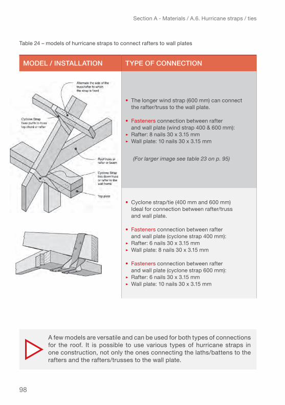
98
Section A - Materials / A.6. Hurricane straps / ties
Table 24 – models of hurricane straps to connect rafters to wall plates
model / i nStAllAtion tYpe of connection
• The longer wind strap (600 mm) can connect the rafter/truss to the wall plate.
• fasteners connection between rafter and wall plate (wind strap 400 & 600 mm):▹ Rafter: 8 nails 30 x 3.15 mm▹ Wall plate: 10 nails 30 x 3.15 mm
(For larger image see table 23 on p. 95)
• Cyclone strap/tie (400 mm and 600 mm) Ideal for connection between rafter/truss and wall plate.
• fasteners connection between rafter and wall plate (cyclone strap 400 mm):▹ Rafter: 6 nails 30 x 3.15 mm▹ Wall plate: 8 nails 30 x 3.15 mm
• fasteners connection between rafter and wall plate (cyclone strap 600 mm):▹ Rafter: 6 nails 30 x 3.15 mm▹ Wall plate: 10 nails 30 x 3.15 mm
A few models are versatile and can be used for both types of connections for the roof. It is possible to use various types of hurricane straps in one construction, not only the ones connecting the laths/battens to the rafters and the rafters/trusses to the wall plate.

99
Section A - Materials / A.6. Hurricane straps / ties
A.6.4. fAStenerS for hurricAne StrApS And coiled StrApS
There are several types of fasteners for hurricane straps and coiled straps (metal connectors). Often manufacturers provide specific fastener to each particular type of strap. It is recommended to use the matching fasteners.
The table below presents the most commonly used fasteners for hurricane straps:
Table 25 – models of fixings / fasteners used for hurricane straps and coiled straps
tYpe of fAStener
nail 8d x 1 1/2 ”(3.3 x 38.1 mm)
nail 8d common nail 2 1/2 ”(3.3 x 63.5 mm)
nail 10d x 1 1/2 ”(3.8 x 38.1 mm)
nail 30 x 3.15 mm
Structural wood screw (3.3 x 38 mm)

100
Section A - Materials / A.6. Hurricane straps / ties
Common screws should not be used to install hurricane straps, because they are not as resistant to shear forces as nails or the specific structural wood screws.
To ensure the necessary performance it is imperative to use the right type and the right quantity of fasteners to properly install the hurricane straps. Refer to the catalogue of suppliers / manufacturers to identify and select the appropriate type of fasteners for a selected hurricane strap. Always use fasteners and straps of the same quality/alloy (hot-dip galvanized or stainless steel) to avoid galvanic corrosion (also called bimetallic corrosion).
Bangladesh: House with ridge and hip capping. (IFRC-SRU)

101
Section A - Materials / A.7. Roofing accessories: ridge capping and fascia capping
A.7. roofing AcceSSorieS: ridge cApping And fASciA cApping
These roofing accessories, ridge capping and fascia capping, are used to ensure the water tightness of the roof and reduce the risk of uplift of the CGI sheets by covering and securing parts of the roof where the wind pressure is particularly high.
A.7.1. ridge cAp And hip cAp
Ridge caps are galvanized metal sheets designed to cover the ridge of a CGI roof to add protection and stability to this area subject to very high wind pressure. The thickness (gauge) and coating thickness of the ridge caps must be the same as the CGI. To ensure a good overlap of the ridge cap over the CGI sheet, it is recommend-ed to use ridge caps with wings of 15 cm minimum.
Ridge caps can also be used to cover the hip angles of hipped roofs and are then called hip caps.
Pieces of CGI sheet cut lengthwise can be used instead of ridge caps. However, a study* by the Florida International University for the Office of U.S. Foreign Disaster Assistance (OFDA) has shown that these ridge coverings are less resistant than ridge cap designed for this purpose. From an economic point of view, there is little difference in price between buying ridge caps and using pieces of CGI sheets. If available on the market the use of ridge caps is recommended.
Ridge cap
* Source: International Hurricane Research Center, Shelter and Component Testing OFDA transitional shelters: materials, techniques and structures (Supplementary Test)

102
Section A - Materials / A.7. Roofing accessories: ridge capping and fascia capping
Table 26 – Example Technical specifications: Ridge cap (extract from the Emergency Items Catalogue as of 2016)
Philippines: Ridge cap and hip caps. (IFRC-SRU)

103
Section A - Materials / A.7. Roofing accessories: ridge capping and fascia capping
item required vAlue deScription / note
ridge cap, galvanized steel
Steel (base)• Mild steel for forming• Cold rolled steel sheet• Cold forming
• Similar to the Cgi sheets used
grade• DX51D +Z • SgCC• CS
• According to the following standards:▹ European standard EN 10346 (2009)▹ Japanese standard JIS G3302▹ ASTM standard ASTM A653
tensile strength • 300 MPa (N / mm2) • Minimum 270 MPa (N / mm2)• Maximum 500 MPa (N / mm2)
galvanization method • Hot-dip continuous
• Hot-dip galvanizing provides the best protection for CGI sheets. Other methods should be avoided.• According to standards:▹ European standard EN 10346 (2009)▹ Japanese standard JIS G3302▹ ASTM standard ASTM A653
protective coating • zinc
• Should be similar to the corrosion treatment used for the CGI sheets.• Other coatings exist, such as aluminium-zinc, zinc-aluminium or aluminium. More details are provided in 1.7.
zinc coating thickness
• Z275 (ASTM A653 or EN 10346) ▹ 275 g / m2 (40 μm ▹ 20µm / side)
• A minimum of 137.5 g / m2 on each side is recommended ▹ Should be chosen according to the desired service life and environment
thickness
• 26 gauge (0.551 mm) for permanent shelters• 28 gauge (0.475 mm) for transitional shelters• 30 gauge (0.399 mm) for temporary shelters
• Should be identical to the Cgi sheet thickness used• Minimum thickness requirement for:▹ European standards: 0.63 mm (25 gauge)▹ Caribbean recommendations: 0.551–0.701 mm (26–24 gauge)
length • Up to 3 m (10 ft)
width • Minimum 300 mm (2 wings of 150 mm)
• 400 mm recommended (2 wings of 200 mm) minimum overlap between ridge cap and CGI sheet: 150 mm

104
Section A - Materials / A.7. Roofing accessories: ridge capping and fascia capping
A.7.2. fASciA / verge cAp or bArgeboArd flAShing
The fascia caps are placed on the edges of the roof to covering the ends of the CGI sheets and the fascia boards. Their properties are identical to those of the ridge cap, only the shape is different. Fascia caps protect the fascia boards from rain to prevent timber from rotting, and contribute to improve uplift resistance in the roof edge areas where the wind pressure is twice as strong as on the main part of the roof.
It is recommended to use fascia caps with wings of at least 10cm to ensure adequate overlap over the first corrugation of the CGI sheet placed on the edge of the roof. The wings can have different widths. In particular, the wing over the fascia board can be longer in order to completely cover the fascia board and make sure it remains dry.
fascia caps are used for single-pitch, gable and gambrel roofs.
Instead of using fascia caps, it is possible to fold the CGI sheets placed on the edges of the roof over the fascia boards and nail them in place. This method is described in Chapter D – Installation guidelines. It is however less resistant.
Fascia / verge cap
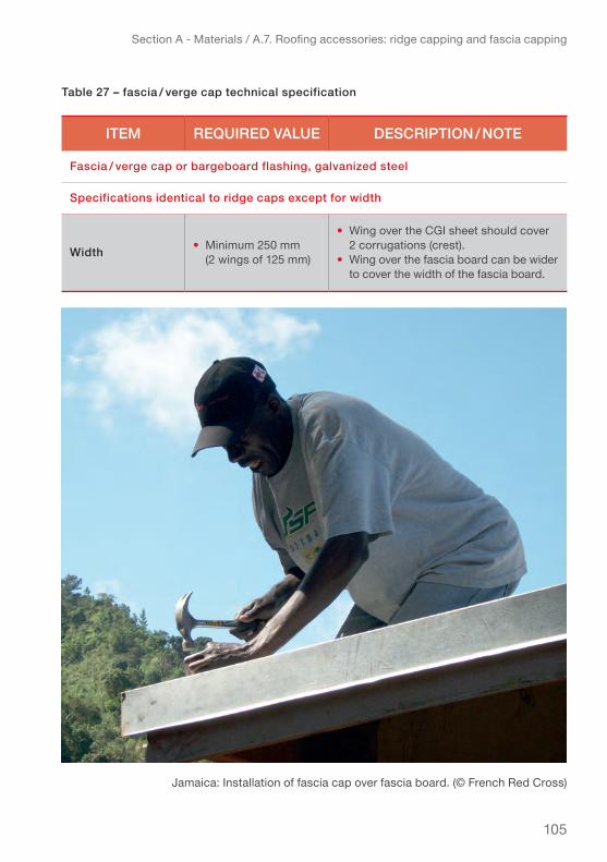
105
Section A - Materials / A.7. Roofing accessories: ridge capping and fascia capping
table 27 – fascia / verge cap technical specification
item required vAlue deScription / note
fascia / verge cap or bargeboard flashing, galvanized steel
Specifications identical to ridge caps except for width
width • Minimum 250 mm (2 wings of 125 mm)
• Wing over the CGI sheet should cover 2 corrugations (crest).• Wing over the fascia board can be wider to cover the width of the fascia board.
Jamaica: Installation of fascia cap over fascia board. (© French Red Cross)
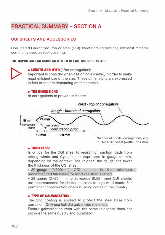
106
Section A - Materials / Practical Summary
prActicAl SummArY – Section A
cgi SheetS And AcceSSorieS
Corrugated Galvanized Iron or steel (CGI) sheets are lightweight, low cost material commonly used as roof covering.
the imPoRtAnt meAsuRements to Define cgi sheets ARe:
● length AnD with (after corrugation): Important to consider when designing a shelter, in order to make most efficient use of the size. These dimensions are expressed in feet or meters depending on the context.
● the Dimensions of corrugations to provide stiffness:
● thickness: Is critical for the CGI sheet to resist high suction loads from strong winds and Cyclones. Is expressed in gauge or mm, depending on the context. The “ higher” the gauge, the lower the thickness of the CGI sheet, ▹ 30-gauge (0.399 mm) Cgi sheets is the minimum recom mended thickness for wind-resistant shelters ▹ 28-gauge (0.475 mm) to 26-gauge (0.551 mm) CGI sheets are recommended for shelters subject to high wind loads. For permanent construction check building codes of the country!
● tyPe of gAlvAnizAtion: The zinc coating is applied to protect the steel base from corrosion. Only use hot-dip galvanized materials. Electro-galvanization even with the same thickness does not provide the same quality and durability!
Number of crests (corrugations) e.g. 12 for a 36” sheet (width = 914 mm)

107
Section A - Materials / Practical Summary
● coAting thickness: The service life (durability) of the CGI sheets depends on the zinc coating thickness and environment that it is exposed to. The zinc coating should be min. 275 g / m2 on each side or 20 µm/side. 20 µm / side coating thickness ensures service life from 2 to 18 years depending on the climate and the environment. A hot and humid climate as well as air pollution and salinity in the air will accelerate corrosion!
an online tool can be used to predict the service life of the Cgi sheet based on the environmental factors http://www.galvinfo.com:8080/zclp/
Generic reference specifications of CGI sheets are available in the IFRC Emergency Items Catalogue (EIC) http://procurement.ifrc.org/catalogue/detail.aspx?itemcode=EBUIBSHEGR20&from=kit
the mAjoR issue foR the DuRABility of cgi sheets is coRRosion
● zinc-Rich PAint can be applied to protect the Cgi sheets and increase their service life or for maintenance (detailed information provided in Chapter e – Roof maintenance and preventive measures)
Coastal area Kuakata, Bangladesh: Anti-corrosion-paint used to protect CGI sheets from corroding, especially in marine environment. (IFRC-SRU)

108
Section A - Materials / Practical Summary
fiXingS / fAStenerS And wASherS:
● Twisted shank roofing nails are the best value for money choice. Only use roofing nails with umbrella head (diameter = 20 mm).
● Smooth-shank roofing nails should only be used in areas not subject to strong winds.
● For very exposed areas with prone to very strong winds (cyclones) the use of roofing screws is advised. Roofing screws need a wide sealing washer (diameter: 25-45 mm) to perform at their best.
● Use additional sealing washers to avoid the CGI sheets tearing off around the nails (unbuttoning) while ensuring the waterproofing of the roof where the sheets are punctured by the roofing nails or screws.
● use rubber washers (diameter = 2mm larger than head of Nail/screw thickness= 2-3 mm) with the fixings to ensure water tightness of the covering.
● Use additional sealing washers to increase the puncture resistance of the sheeting e.g. when the umbrella head is less than 20mm diameter, the CGI is gauge 30 or higher (means a thinner sheet) or withdrawal (or pull-out) resistance of the fixings is higher than the puncture resistance of the CGI.
In order to get optimum performance of all elements, the withdrawal or pull-out resistance of the fasteners should be approximately equal to the maximal puncture resistance of the CGI sheet. Consequently, the thinner the CGI sheet or the strong-er the fixing, the wider the sealing washer required.
Double the quantity of fixings/fasteners around the perimeter of the roof and other areas where the wind pressure is the highest: eaves, verges, hip angles and ridge and also for sheet overlaps.
Fixings/fasteners and sealing washers must be made of galvanized steel, with similar zinc coating thickness as the CGI sheet they are used to fasten, in order to have equal service life and avoid early corrosion and breakage.For bamboo, J-hooks or a special fixing called “German wire” (in the Philippines) can be used (see p.80) Do NOT use roofing

109
Section A - Materials / Practical Summary
nails and self-piercing roofing screws for Bamboo, they will very likely split the bamboo and reduce stability.
For metal purlins use special self-drilling metal screws or L-hooks.
roof AcceSSorieS:
● To strengthen the roof and provide better water proofing and resistance to strong winds use ridge caps on the ridge, hip caps on the hip angles and fascia caps along the verges of the roof.
● The ridge- hip- and fascia caps should be of the same thickness and quality as the CGI sheets used to cover the roof.
● use Hurricane straps to reinforce the roof structure to resist high wind loads. They should be made of hot-dip galvanized steel (zinc coating = 350–450 g/m2) or stainless steel.
● Hurricane straps connecting laths/battens to rafters need to withstand a vertical force (tensile loads) while hurricane straps connecting rafters to wall plates should withstand a vertical and a horizontal force (tensile and shear loads). Only a few hurricane straps can fit both types of connections for the roof!
● The coiled strap can only be used to connect the laths/bat-tens to the rafters NOT rafters to wall plate!To help you choose which hurricane straps are suitable for your roof, you need to run the Roof Estimate Form – Excel spread-sheet Annex 7.
● Fasteners for hurricane straps are specific. They are usually nails described as short and fat. Common sizes: diameter = 3.3 or 3.8 mm, length = 38 and 63 mm (1½ and 2½ in). Use the fas-teners that are provided with the hurricane strap.

110
Section A - Materials / Practical Summary
PRActicAl t iPs for purchASing cgi SheetS And other gAlvAnized Steel itemS:
● For the specification of the thickness give both indications, gauge, mm and the standard you are specifying to avoid confusion or misunderstanding and ideally indicate the standard you are using as reference (european: EN, japanese: JIS, US: ASTM, etc.)
● Use the tables (Chapter A.2.5.) or the Zinc coating life predictor to identify necessary coating thickness for desired service life in your specific context. If you don’t have the necessary information, CGI hot-dip galvanized steel sheets with zinc coating thickness of 20 µm / side or the equivalent of 275g / m2 (Z275 according to the ASTM and EN) should be an adequate choice in most cases.
● Verify the zinc coating thickness, by using a coating thickness gauge – magnetometer (see Chapter B for more detail),
● If the price for items made of galvanized steel seems expensive, you should check if the items are not made of stainless steel (3 times more expensive than galvanized steel). Test with a magnet if the magnet does not stick, then it is made of stainless steel.
● When buying galvanized steel items which are intended to be in con-tact with the ground (anchors), the zinc coating thickness should be approximately 30 µm / side or the equivalent of 400g / m2 (Z350–Z450 according to the ASTM and EN).
Beware, the supplier may try to sell electro-galvanized steel which looks like hot-dip galvanized but can have a zinc coating thickness 10 times thinner!
111
Section A - Materials / Practical Summary
SupportS for cgi SheetS: lumber / timber, coconut lumber, bAmboo And metAl
All four support materials present advantages and disadvantages based on their use and context of the project.
● To ensure good withdrawal resistance the supports (laths / bat-tens / purlins) made of timber or coconut lumber should be thick and wide enough to avoid the nails or screws piercing through or splitting the support. Recommended size: approximately 38 x 64 mm (2 x 3 in) placed flat.
● Coconut lumber used for laths / battens should be of high-density (from the lower part of the trunk); the higher part of the trunk is softer and not sufficient in quality.
● Bamboo is generally a construction material with great mechanical properties (resistance) for construction, but make sure to confirm the local variety for building construction. It needs specific fixings, such as “german wire” to fasten CGI roofing sheets.
● Timber, coconut wood or bamboo used for construction should be treated against fungus and insects.
● Metal purlins should be made of hot-dip galvanized steel (minimum zinc coating mass = 350 g/m2) or stainless steel, to offer better resistance in harsh environments (marine, industrial or highly polluted urban).
112
Section B – Quality control / B.1. Basic safety equipment
This Chapter presents instruments and simple tests to check the quality of the CGI sheets, advice for safe transport and proper storage as well as important safety measures for handling CGI sheeting.
b.1. bASic SAfetY equipmentFor each task on a construction site – from unloading, checking the quality, trans-porting and storing the materials to building the shelter – adequate safety equipment should be worn by the workers (volunteers, beneficiaries and supervisor) and people visiting the site to avoid any injury. Make sure the workers and volunteers are insured (IFRC can provide special deal insurance packages for RCRC volunteers).
● PRoPeR clothing▹ Do not wear very loose clothing that can increase risk of accident
(tripping getting caught etc.). ▹ Restrain long hair.▹ Remove loose jewellery, necklaces, bracelets
and any “dangling” items.
● PRoPeR footweAR:▹ Construction workers should wear work shoes or boots
with slip-resistant and puncture-resistant soles.
● woRk gloves:▹ Workers should wear the correct gloves for the job,
especially when handling the CGI sheets.
● helmet: ▹ Workers should wear hard hats where there is a potential for objects
falling from above, bumps to their heads from fixed objects, or of accidental head contact with electrical hazards.
Always keep a well equipped first aid kit easily accessible on the site!
Section b – QualIty control, transportatIon and storage, basIc safety eQuIpment

113
Section B – Quality control / B.1. Basic safety equipment
● sAfety glAsses:▹ Safety glasses or face shields are
worn anytime work operations can cause foreign objects to get into the eye.
● heARing PRotection:▹ When working with power tools for
a prolonged period of time, hearing protection should be worn
the following ARe high Risk on A constRuction site AnD shoulD not Be useD:
● Headphones ● Sandals, tennis shoes● Shorts
St Vincent & the Grenadines, hurricane Tomas, 2010: A RC volunteer carrying a CGI sheet for covering a roof. (© French Red Cross)
RC volunteer wearing a helmet while installing a hurricane strap. (© French Red Cross)

114
Section B – Quality control / B.2. Quality control of the CGI sheet and other galvanized items
b.2. quAlitY control of the cgi Sheet And other gAlvAnized itemS
It is very important to verify the quality of the CGI sheets and other galvanized items when receiving the delivery, to ensure that the products meet the specifications ordered1 and will thus be of the quality that you need to build safe roofs for shelter project. Of course you also want to receive the value for money products that you ordered. Be aware that in the construction industry and related suppliers, there are huge gains (or losses) to be made with small changes of specification that are often not checked. This needs to be taken seriously, even if under pressure, or you risk losing money quality in the shelter products ordered. This Chapter presents some basic tests that can easily be carried out to verify the quality using basic instruments such as: measuring tape, scale, calliper and magnetic instruments. all the proposed tests presented in this Chapter are non-destructive.
The parameters you should check are:● the dimensions of the Cgi sheet● the zinc coating thickness2 ● the quality of the zinc coating through the appearance of the CGI sheet
minimum numBeR of sAmPles:Especially when receiving large quantities of CGI sheeting the quality control of the Cgi sheets should be carried out on a large enough number of samples to be rep-resentative of all CGI sheets ordered. The checks should be undertaken on several CGI sheets taken at random from various bundles. The European Standard, EN ISO 1461, suggests the following number of samples depending on the number of galva-nized items:
Table 28 – Number of samples depending on the quantity of items
1 For very large RCRC construction projects the checking of goods received against the specifications they were procured under may be undertaken by an external company specialised in this task.2 The coating thickness refers to the thickness of zinc applied to steel or iron.
Number of units / items received 1 – 500 501 – 1200 1201 – 3200 3201 – 10000 > 10000
Number of samples to test 3 5 8 13 20
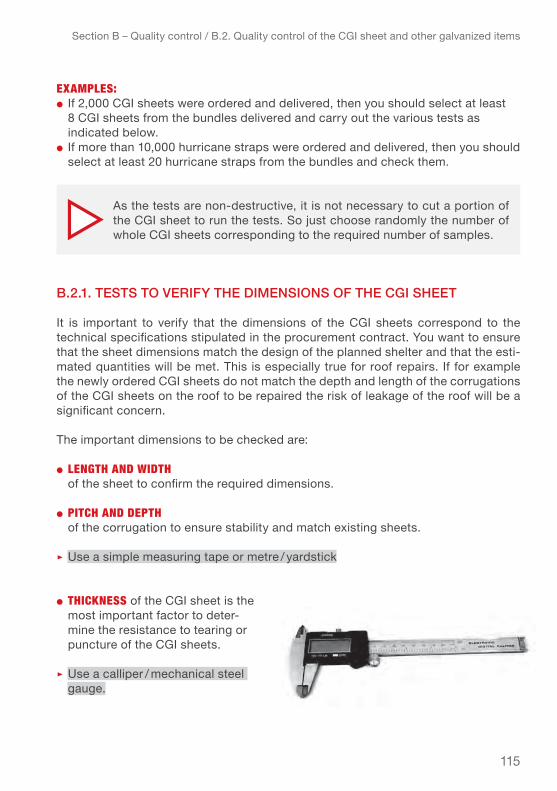
115
Section B – Quality control / B.2. Quality control of the CGI sheet and other galvanized items
eXAmPles:● If 2,000 CGI sheets were ordered and delivered, then you should select at least
8 CGI sheets from the bundles delivered and carry out the various tests as indicated below.
● If more than 10,000 hurricane straps were ordered and delivered, then you should select at least 20 hurricane straps from the bundles and check them.
b.2.1. teStS to verifY the dimenSionS of the cgi Sheet
It is important to verify that the dimensions of the CGI sheets correspond to the technical specifications stipulated in the procurement contract. You want to ensure that the sheet dimensions match the design of the planned shelter and that the esti-mated quantities will be met. This is especially true for roof repairs. If for example the newly ordered CGI sheets do not match the depth and length of the corrugations of the CGI sheets on the roof to be repaired the risk of leakage of the roof will be a significant concern.
The important dimensions to be checked are:
● length AnD wiDth of the sheet to confirm the required dimensions.
● Pitch AnD DePth of the corrugation to ensure stability and match existing sheets.
▹ Use a simple measuring tape or metre / yardstick
● thickness of the Cgi sheet is the most important factor to deter-mine the resistance to tearing or puncture of the CGI sheets.
▹ use a calliper / mechanical steel gauge.
As the tests are non-destructive, it is not necessary to cut a portion of the CGI sheet to run the tests. So just choose randomly the number of whole CGI sheets corresponding to the required number of samples.

116
Section B – Quality control / B.2. Quality control of the CGI sheet and other galvanized items
● weight check the weight of the CGI sheet and relate it to the dimensions can help to confirm the thickness and density of the material if no other options are available. The density of different CGI sheet thickness is available in Annex 1 – Galvanized steel sheet conversion table.
▹ use a scale
The table below gives the tolerances for each of the measurement to verify which tool or instrument should be used to verify the dimensions of the CGI sheets, and the method to apply. It also provides the tolerance for each type of verification.
Table 29 – Measurement tolerance for verification of dimensions of CGI sheet
verificAtion (unit) tolerAnce method tool /
inStrument
Thickness (mm): ± 0.05 mm Measure with Calliper
Length (mm) - 0 mm, + 15 mm Measure with Measuring tape or stick
Width (mm) - 0 mm, + 7 mm Measure with Measuring tape or stick
Pitch & depth of the corrugation – Measure with Measuring tape
or stick
Weight of the CGI sheet (kg) – Measure with Scale (e.g. portable
suitcase scale)
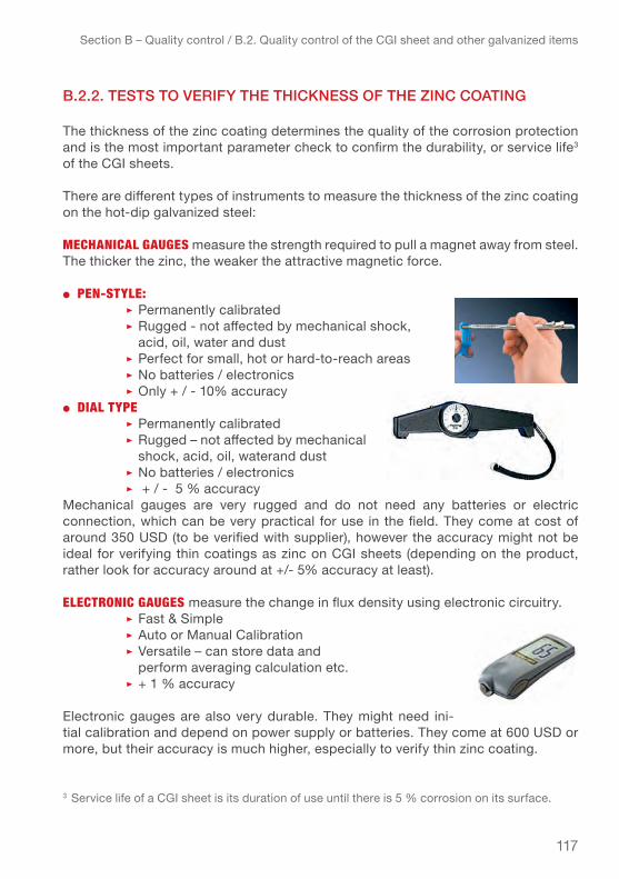
117
Section B – Quality control / B.2. Quality control of the CGI sheet and other galvanized items
b.2.2. teStS to verifY the thickneSS of the zinc coAting
The thickness of the zinc coating determines the quality of the corrosion protection and is the most important parameter check to confirm the durability, or service life3 of the CGI sheets.
There are different types of instruments to measure the thickness of the zinc coating on the hot-dip galvanized steel:
mechAnicAl gAuges measure the strength required to pull a magnet away from steel. The thicker the zinc, the weaker the attractive magnetic force.
● Pen-style:▹ Permanently calibrated▹ Rugged - not affected by mechanical shock, acid, oil, water and dust▹ Perfect for small, hot or hard-to-reach areas▹ No batteries / electronics▹ Only + / - 10% accuracy
● DiAl tyPe▹ Permanently calibrated▹ Rugged – not affected by mechanical shock, acid, oil, waterand dust ▹ No batteries / electronics▹ + / - 5 % accuracy
Mechanical gauges are very rugged and do not need any batteries or electric connection, which can be very practical for use in the field. They come at cost of around 350 USD (to be verified with supplier), however the accuracy might not be ideal for verifying thin coatings as zinc on CGI sheets (depending on the product, rather look for accuracy around at +/- 5% accuracy at least).
electRonic gAuges measure the change in flux density using electronic circuitry.▹ Fast & Simple▹ auto or Manual Calibration▹ versatile – can store data and perform averaging calculation etc.▹ + 1 % accuracy
Electronic gauges are also very durable. They might need ini-tial calibration and depend on power supply or batteries. They come at 600 USD or more, but their accuracy is much higher, especially to verify thin zinc coating.
3 Service life of a CGI sheet is its duration of use until there is 5 % corrosion on its surface.

118
Section B – Quality control / B.2. Quality control of the CGI sheet and other galvanized items
Choose an instrument which is accurate enough, easy to use in the field, and if possible, which does not need to be calibrated for each use.
meAsuRing the coAting thickness on cgi sheet sAmPles:
● Measurements should be carried out on 3 reference areas of at least 10 cm2 each (as shown in the drawing on the next page).
● at least 5 measurements must be taken in each reference area to be representative of the average value.
● Reference areas should be located at various places on the CGI sheet.● Measurements on CGI sheets must be made at least 10 cm from the edges.● Measurements must be undertaken on both sides of the CGI sheet (1 measure-
ment on top of the CGI and 1 measurement on the underside of the CGI sheet) to be able to compare the results to the minimum values required by the standards (see Table 29 – Measurement tolerance for verification of dimensions of CGI sheet).
▹ These recommendations are taken from European standard EN ISO 1461. The recommendations for reading the measurements in samples are similar for ASTM (American) and Japanese standards.
Make sure that the tool you select can measure the zinc coating thickness on the thin base material that you want to use it for (iron or steel – fer-rous base; “critical thickness of the base” approx. 0.3 mm). Not every instrument measures zinc coating thickness on very thin material such as CGI sheets (displaying accuracy of minimum 10μm or less for the zing coating).
Even if the cost might be up to 1000 USD for a high quality instrument it is cheap compared to the cost of a bad purchase.
Measurements should not be done close to the edges.
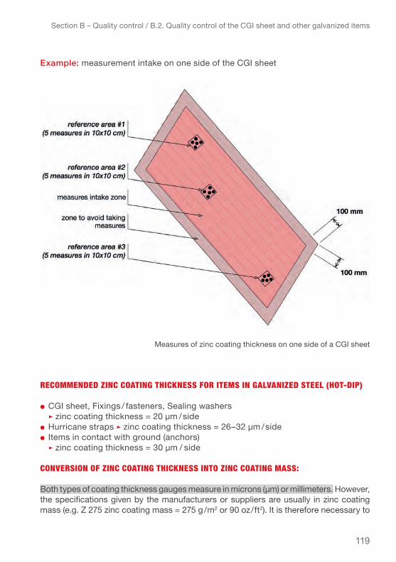
119
Section B – Quality control / B.2. Quality control of the CGI sheet and other galvanized items
example: measurement intake on one side of the CGI sheet
RecommenDeD zinc coAting thickness foR items in gAlvAnizeD steel (hot-DiP)
● CGI sheet, Fixings / fasteners, Sealing washers ▹ zinc coating thickness = 20 µm /side● Hurricane straps ▹ zinc coating thickness = 26–32 µm /side● Items in contact with ground (anchors) ▹ zinc coating thickness = 30 µm / side
conveRsion of zinc coAting thickness into zinc coAting mAss:
Both types of coating thickness gauges measure in microns (µm) or millimeters. However, the specifications given by the manufacturers or suppliers are usually in zinc coating mass (e.g. Z 275 zinc coating mass = 275 g /m2 or 90 oz/ft2). It is therefore necessary to
Measures of zinc coating thickness on one side of a CGI sheet

120
Section B – Quality control / B.2. Quality control of the CGI sheet and other galvanized items
know how to convert the thickness (µm) into coating mass (g/m2) in order to verify that the measured thicknesses are consistent with the specifications you ordered. To convert the thickness of zinc coating, it is necessary to know the density of the zinc. The density of the zinc is 7140 kg /m3 or 7.14 t /m3. Therefore, a thickness of 1 micron of zinc is equivalent to 7.14 g/m2.
● To convert zinc coating thickness to zinc coating mass:▹ zinc coating mass (g/m2) = thickness (µm) x density (t/m3)
● To convert zinc coating mass to zinc coating thickness:▹ zinc coating thickness (µm) = mass (g/m2) / density (t/m3)
eXAmPle: zinc coating thickness measured on one side of the CGI sheet is 20 µm. Then, the zinc coating mass is equal to: 20 x 7.14 = 135.66 g / m2 of zinc on one side.
Table 30 – Minimum values required according to standards
ASTM Standards(ASTM A653 / A653M) Zinc coating designation (inch-pound)
G30 G40 G60 G90 G115 G140 G165 G185
ASTM Standards(ASTM A653 / A653M) Zinc coating designation (SI metric)
Z90 Z120 Z180 Z275 Z350 Z450 Z500 Z550 Z600
European StandardsChapter 3 (EN ISO 10346) Zinc coating designation (SI metric)
Z100 Z150 Z225 Z275 Z350 Z450 Z600
Japanese Standards (JIS G3302)Zinc coating designation*
Z08 Z10 Z12 Z18 Z20 z22 Z25 Z27 Z35 Z45 Z60
Average coating mass (g/m2) in triple-spot test
80 90 100 100 120 120 150 180 180 200 220 225 250 275 275 350 350 450 450 500 550 600 600
Minimum coating mass (g/m2) at a single spot (for both sides)
68 76 85 85 102 102 128 153 153 170 187 192 213 234 235 298 299 383 384 427 470 510 512
Zinc coating thickness (µm) for one Side
8 6 10 7 13 8 10 17 12 20 21 15 24 27 19 32 24 40 31 35 38 51 41
* Zinc coating designation for Japanese standards presents a minimum zinc coating thickness which is higher than ASTM and European standards. This difference suggests that the coating is not pure zinc but an alloy of zinc and aluminium. This information has not been confirmed yet. Meanwhile, we suggest that you base your choice of zinc coating on ASTM or EN.

121
Section B – Quality control / B.2. Quality control of the CGI sheet and other galvanized items
zinc coAting thickness minimum vAlues AccoRDing to stAnDARDs:
According to the ASTM and Japanese standards three tests should be carried out in order to verify the zinc coating thickness:
● triple-spot test (tSt)1. made on the 3 reference areas on both sides (total mass on both sides) 2. made on the 3 reference areas on ONE side
● Single-spot test (SSt) – made on the 3 reference areas on both sides
To know the zinc mass on both sides, it is necessary to measure the thickness of zinc coating on the top and on the underside of the CGI sheet. Then, convert these values to coating mass (as explained above) and add them to obtain the total coating mass on both sides of the CGI sheet.
ASTM Standards(ASTM A653 / A653M) Zinc coating designation (inch-pound)
G30 G40 G60 G90 G115 G140 G165 G185
ASTM Standards(ASTM A653 / A653M) Zinc coating designation (SI metric)
Z90 Z120 Z180 Z275 Z350 Z450 Z500 Z550 Z600
European StandardsChapter 3 (EN ISO 10346) Zinc coating designation (SI metric)
Z100 Z150 Z225 Z275 Z350 Z450 Z600
Japanese Standards (JIS G3302)Zinc coating designation*
Z08 Z10 Z12 Z18 Z20 z22 Z25 Z27 Z35 Z45 Z60
Average coating mass (g/m2) in triple-spot test
80 90 100 100 120 120 150 180 180 200 220 225 250 275 275 350 350 450 450 500 550 600 600
Minimum coating mass (g/m2) at a single spot (for both sides)
68 76 85 85 102 102 128 153 153 170 187 192 213 234 235 298 299 383 384 427 470 510 512
Zinc coating thickness (µm) for one Side
8 6 10 7 13 8 10 17 12 20 21 15 24 27 19 32 24 40 31 35 38 51 41
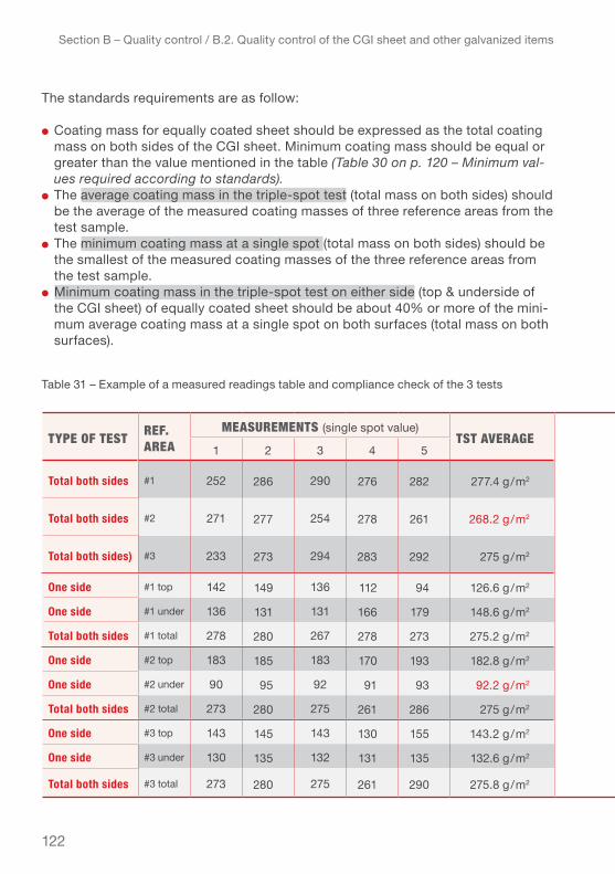
122
Section B – Quality control / B.2. Quality control of the CGI sheet and other galvanized items
The standards requirements are as follow:
● Coating mass for equally coated sheet should be expressed as the total coating mass on both sides of the CGI sheet. Minimum coating mass should be equal or greater than the value mentioned in the table (Table 30 on p. 120 – Minimum val-ues required according to standards).
● the average coating mass in the triple-spot test (total mass on both sides) should be the average of the measured coating masses of three reference areas from the test sample.
● the minimum coating mass at a single spot (total mass on both sides) should be the smallest of the measured coating masses of the three reference areas from the test sample.
● Minimum coating mass in the triple-spot test on either side (top & underside of the CGI sheet) of equally coated sheet should be about 40% or more of the mini-mum average coating mass at a single spot on both surfaces (total mass on both surfaces).
tyPe of test Ref. AReA
meAsuRements (single spot value)tst AveRAge comments
1 2 3 4 5
Total both sides #1 252 286 290 276 282 277.4 g/m2 OK, meets the minimum TST one side and both sides requirements
Total both sides #2 271 277 254 278 261 268.2 g/m2 Does not meet the minimum TST average requirements
Total both sides) #3 233 273 294 283 292 275 g/m2 Does not meet the minimum SST require-ments
One side #1 top 142 149 136 112 94 126.6 g/m2
OK, meets the minimum TST one side and both sides requirementsOne side #1 under 136 131 131 166 179 148.6 g/m2
Total both sides #1 total 278 280 267 278 273 275.2 g/m2
One side #2 top 183 185 183 170 193 182.8 g/m2
Does not meet the minimum TST average on one side requirementOne side #2 under 90 95 92 91 93 92.2 g/m2
Total both sides #2 total 273 280 275 261 286 275 g/m2
One side #3 top 143 145 143 130 155 143.2 g/m2
OK, meets the minimum TST one side and both sides requirements
One side #3 under 130 135 132 131 135 132.6 g/m2
Total both sides #3 total 273 280 275 261 290 275.8 g/m2
Table 31 – Example of a measured readings table and compliance check of the 3 tests

123
Section B – Quality control / B.2. Quality control of the CGI sheet and other galvanized items
eXAmPle: This example shows the measured readings table and the compliance check of the 3 tests for a CGI sheet with a Z275 coating.
CGI sheet with a Z275 coating ▹ coating mass = 275 g/m2 for both sides / equivalent of 38 µm thickness for both sides (19 x 2 = 38 µm)
According to the Table 30 – Minimum values required according to standards (p.120), the standards requirements are:
● Minimum TST (triple-spot test) average value – total both sides: 275 g/m2
● Minimum SST (single-spot test) value – total both sides: 235 g/m2
● Minimum TST (triple-spot test) average value – ONE SIDE: 93 g/m2 (235 x 40% = 93 g/m2)
The table 31 shows the values measured on the tested CGI sheet, the results of the average calculation and the compliance check for the tests (Triple-spot test – TST, single-spot test – SST).
Standards give different variables of tolerances for the different dimensions. For
the zinc coating thickness if one test sample fails to conform, another two samples from the same lot shall be tested. If another one fails the whole lot can be rejected.
if the non-compliance with the speci-fications is not too high (depending on what dimension / measurement, it can be between 0.5 and 5%) rejecting the delivery might not be in the interest of the operation. However a price reduction can be negotiated.
tyPe of test Ref. AReA
meAsuRements (single spot value)tst AveRAge comments
1 2 3 4 5
Total both sides #1 252 286 290 276 282 277.4 g/m2 OK, meets the minimum TST one side and both sides requirements
Total both sides #2 271 277 254 278 261 268.2 g/m2 Does not meet the minimum TST average requirements
Total both sides) #3 233 273 294 283 292 275 g/m2 Does not meet the minimum SST require-ments
One side #1 top 142 149 136 112 94 126.6 g/m2
OK, meets the minimum TST one side and both sides requirementsOne side #1 under 136 131 131 166 179 148.6 g/m2
Total both sides #1 total 278 280 267 278 273 275.2 g/m2
One side #2 top 183 185 183 170 193 182.8 g/m2
Does not meet the minimum TST average on one side requirementOne side #2 under 90 95 92 91 93 92.2 g/m2
Total both sides #2 total 273 280 275 261 286 275 g/m2
One side #3 top 143 145 143 130 155 143.2 g/m2
OK, meets the minimum TST one side and both sides requirements
One side #3 under 130 135 132 131 135 132.6 g/m2
Total both sides #3 total 273 280 275 261 290 275.8 g/m2
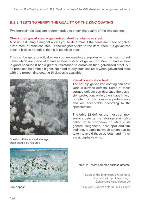
124
Section B – Quality control / B.2. Quality control of the CGI sheet and other galvanized items
b.2.3. teStS to verifY the quAlitY of the zinc coAting
Two more simple tests are recommended to check the quality of the zinc coating:
check the type of steel – galvanized steel vs. stainless steel:A basic test using a magnet allows you to determine if the items are made of galva-nized steel or stainless steel. If the magnet sticks to the item, then it is galvanized steel. If it does not stick, then it is stainless steel.
This can be quite practical when you are meeting a supplier who may want to sell items which are made of stainless steel instead of galvanized steel. Stainless steel is good because it has a greater resistance to corrosion than galvanized steel, but its price can be 3 times higher. No need to buy stainless steel when galvanized steel with the proper zinc coating thickness is available.
visual observation test:The hot-dip galvanized coating can have various surface defects. Some of these surface defects can decrease the corro-sion protection, while others have little or no effect on the corrosion performance and are acceptable according to the specification.
The table 32 defines the most common surface defects: wet storage stain (also called white corrosion or white rust), general roughness, bare spot and flux staining. It explains which action can be taken to avoid these defects, and if they are acceptable or not.
Table 32 – Most common surface defects*
* Source: The Engineers & Architects’ Guide: Hot Dip Galvanizing – Galvanizers Association UK
** Source: European Norm EN ISO 1461
Sheets with heavy wet storage stain should be rejected
Flux deposit
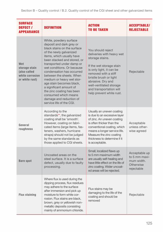
125
Section B – Quality control / B.2. Quality control of the CGI sheet and other galvanized items
suRfAce Defect / APPeARAnce
Definition Action to Be tAken
AccePtABle/RejectABle
Wet storage stain (also called white corrosion or white rust)
White, powdery surface deposit and dark grey or black stains on the surface of the newly galvanized items, which usually have been stacked and stored, or transported under damp or wet conditions. Or because condensation has occurred between the sheets. When medium or heavy wet stor-age stain becomes black, a significant amount of the zinc coating has been consumed which means damage and reduction of service life of the CGI.
You should reject deliveries with heavy wet storage stains.
If the wet storage stain is only light, it can be removed with a stiff bristle brush or light abrasive. Dry and well-ventilated storage and transportation will help prevent white rust.
Rejectable
General roughness
According to the standards**, the galvanized coating shall be ‘smooth’. However, coating on fabri-cated items (large items, fas-teners, washers, hurricane straps) should not be judged by the same standards as those applied to CGI sheets.
Usually an uneven coating is due to an excessive layer of zinc. An uneven coating is often thicker than the conventional coating, which means a longer service life. Measure the zinc coating thickness to determine if it is acceptable.
acceptable unless other-wise agreed
Bare spot
uncoated areas on the steel surface. It is a surface defect, usually due to faulty processing.
Small, localized flaws up to 5 mm maximum width are usually self-healing and have little effect on the life of zinc coating. Wider uncoat-ed areas will be rejected.
acceptable up to 5 mm maxi-mum width. otherwise rejectable
Flux staining
Where flux is used during the dipping process, flux residues may adhere to the surface after immersion and pick up moisture to form white cor-rosion. Flux stains are black, brown, grey or yellowish non-metallic deposits consisting mainly of ammonium chloride.
Flux stains may be damaging to the life of the coating and should be removed
Rejectable
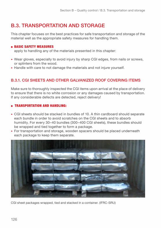
126
Section B – Quality control / B.3. Transportation and storage
b.3. trAnSportAtion And StorAgeThis chapter focuses on the best practices for safe transportation and storage of the material well as the appropriate safety measures for handling them.
● BAsic sAfety meAsuRes apply to handling any of the materials presented in this chapter:
▹ Wear gloves, especially to avoid injury by sharp CGI edges, from nails or screws, or splinters from the wood.
▹ Handle with care to not damage the materials and not injure yourself.
b.3.1. cgi SheetS And other gAlvAnized roof covering itemS
Make sure to thoroughly inspected the CGI items upon arrival at the place of delivery to ensure that there is no white corrosion or any damages caused by transportation. If any considerable defects are detected, reject delivery!
● tRAnsPoRtAtion AnD hAnDling:
▹ CGI sheets should be stacked in bundles of 10. A thin cardboard should separate each bundle in order to avoid scratches on the Cgi sheets and to absorb humidity. For every 30–40 bundles (300–400 CGI sheets), these bundles should be wrapped and tied together to form a package.
▹ For transportation and storage, wooden spacers should be placed underneath each package to keep them separate.
CGI sheet packages wrapped, tied and stacked in a container. (IFRC-SRU)
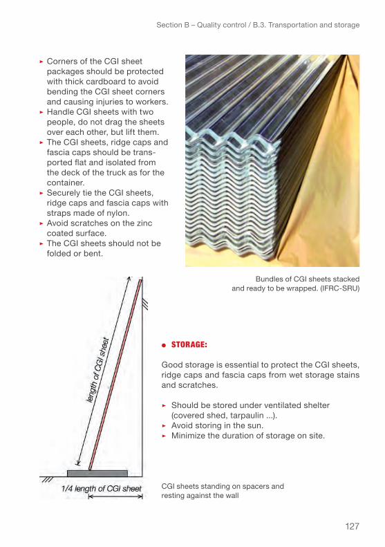
127
Section B – Quality control / B.3. Transportation and storage
▹ Corners of the Cgi sheet packages should be protected with thick cardboard to avoid bending the CGI sheet corners and causing injuries to workers.
▹ Handle Cgi sheets with two people, do not drag the sheets over each other, but lift them.
▹ The CGI sheets, ridge caps and fascia caps should be trans-ported flat and isolated from the deck of the truck as for the container.
▹ Securely tie the CGI sheets, ridge caps and fascia caps with straps made of nylon.
▹ Avoid scratches on the zinc coated surface.
▹ the Cgi sheets should not be folded or bent.
● stoRAge:
Good storage is essential to protect the CGI sheets, ridge caps and fascia caps from wet storage stains and scratches.
▹ Should be stored under ventilated shelter (covered shed, tarpaulin ...). ▹ Avoid storing in the sun.▹ Minimize the duration of storage on site.
Bundles of CGI sheets stacked and ready to be wrapped. (IFRC-SRU)
CGI sheets standing on spacers and resting against the wall

128
▹ Store dry and well ventilated ideally with cardboard or plastic spacers between the sheets and on gently sloping wooden supports or leaning against the wall to facilitate the discharge of the condensed water.
▹ The CGI sheets of great length should be supported in the middle as well.▹ If the CGI sheets, ridge caps and fascia caps are stored outside for a short
time, it is best to store them vertically in order to allow the water from rain or condensation to evacuate quickly.
▹ The CGI sheets, ridge caps and fascia caps should remain dry until installation.▹ Avoid scratches and any other damage to the surface of the CGI sheets.
● fiXings / fAsteneRs, wAsheRs AnD huRRicAne stRAPs
▹ Should be transported in cardboard boxes.▹ Avoid carrying the fasteners and hurricane straps in plastic bags, as their sharp
edges will pierce and cut open the bags.▹ As all other galvanized items they should be kept dry and well ventilated to avoid
white rust and other damage.
Section B – Quality control / B.3. Transportation and storage
Condensation between the CGI sheets, ridge caps and fascia caps can cause wet storage stains (white, powdery corrosion and dark stains) that damage the sheets.
Long CGI sheets placed on spacers and supported in the middle

129
b.3.2. lumber / timber, coconut wood And bAmboo
All the materials should be kept dry and protected from any moisture both from above or from the ground.
● tRAnsPoRtAtion AnD hAnDling:
▹ Elevate the lumber, coconut wood and bamboo from the deck of the truck by placing wood spacers at regular intervals.
▹ Securely tie the lumber, coconut wood and bamboo with straps when transporting on a truck or pick-up.
▹ Handling the lumber, coconut wood and bamboo should preferably be carried out by two people.
▹ Do not drag or throw the lumber, coconut wood and bamboo, but lift the pieces.
Section B – Quality control / B.3. Transportation and storage
Jamaica, Hurricane Dean, 2008: Lumber elevated from the deck of the truck and tied with straps. (© French Red Cross)
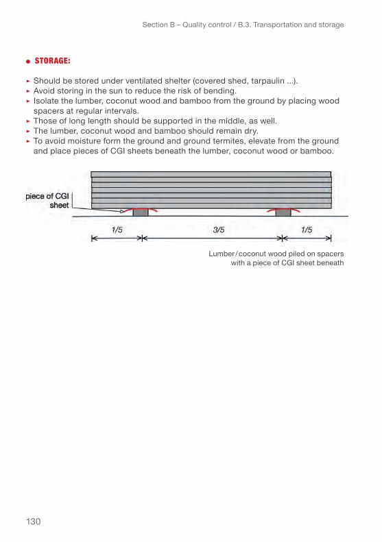
130
● stoRAge:
▹ Should be stored under ventilated shelter (covered shed, tarpaulin ...).▹ Avoid storing in the sun to reduce the risk of bending.▹ Isolate the lumber, coconut wood and bamboo from the ground by placing wood
spacers at regular intervals.▹ Those of long length should be supported in the middle, as well.▹ The lumber, coconut wood and bamboo should remain dry.▹ To avoid moisture form the ground and ground termites, elevate from the ground
and place pieces of CGI sheets beneath the lumber, coconut wood or bamboo.
Section B – Quality control / B.3. Transportation and storage
Lumber / coconut wood piled on spacers with a piece of Cgi sheet beneath
131
Section B – Quality control / Practical Summary
prActicAl SummArY – Section b
bASic SAfetY equipment:
● To handle CGI sheets and other construction materials wear gloves and for con-struction works, helmet, proper clothing and safety shoes.
quAlitY control:
● For Quality control of CGI items check the dimensions, the weight and the zinc coating thickness.
● the basic instruments to check the quality of the CGI sheets and other galvanized materials are: measuring tape, calliper, coating thickness gauge and magnet.
● Verifying the zinc coating thickness is crucial to ensure the service life of the roof covering. The procedure is a bit complex and is explained in detail in this chapter. When purchasing large quantities of CGI sheets, it is highly recommended to undertake a trouble to do a proper quality control procedure when receiving the order. Orders not conforming to the specifications should be rejected or at least subject to price reduction!
● Basic values of zinc coating thickness for items in galvanized steel (hot-dip): ▹ Cgi sheet ▹ zinc coating thickness = 20 µm/side ▹ Fixings/ fasteners ▹ zinc coating thickness = 20 µm/side ▹ Hurricane straps, metal purlins ▹ zinc coating thickness = 26–32 µm/side ▹ Items in contact with ground (anchors) ▹ zinc coating thickness = 30 µm/side
● Using a magnet allows you to determine if the item you want to test is made of galvanized steel or stainless steel. The magnet will not stick to stainless steel!
trAnSportAtion And StorAge:
● Proper transportation and storage conditions are essential to protect the materials, especially the CGI sheets and lumber / coconut wood / bamboo from deterioration and damage. These include:
▹ Storing in a dry and well-ventilated area and protected from any humi dity. ▹ Elevating the materials from the ground for transportation and storage.

132
Section C – Roof shape and pitch / C.1. Effects of wind and earthquakes on structures
This chapter highlights the importance of the design and orientation of a shelter to optimize wind resistance. It describes how wind loads effect a structure, gives basic guidance for orientation of the shelter on the site, design and distribution of open-ings, and most importantly on the choice of roof shape and pitch. Roof shapes and relevant details like eaves overhang and verge length are analysed with regard to their resistance to expected wind speeds in the given context (type of terrain) as well as water tightness.
The analysis of the different roof shapes and pitches is based on engineering calcu-lations using a shelter model designed for the typhoon Haiyan give year response in the Philippines.
c 1. effectS of wind And eArthquAkeS on StructureS
During strong winds and earthquakes, a structure is subjected to forces that can have different effects on the building depending on the structural weaknesses. The effects of wind pressure can be rather similar to the effects that seismic tremors have. The buildings can be lifted, start leaning, sliding or even overturn, if the important struc-tural elements like bracing and anchoring/foundation are not properly dimensioned to resist these effects. The forces that impact the roof and roof cladding are mainly vertical forces such as suction, causing the uplift effect.
c 1.1. generAl effectS of Strong windS And eArthquAkeS on StructureS
● sliDing: when a building is sub jected to strong horizont al forces due to wind or seismic tremors, and the building is not well anchored to the foundations (or has no foundations), the building can start sliding.
Sliding effect
Section c – roof shape and pItch

133
Section C – Roof shape and pitch / C.1. Effects of wind and earthquakes on structures
● RAcking: when a building is subjected to strong horizontal forces due to the wind or seismic tremors, and not well braced (lacking shear walls or diagonal braces in the structure) the building can start leaning to one side.
● oveRtuRning: when a building is sub-jected to strong horizontal forces due to the wind or seismic tremors, and the building is not well anchored or has no or too small foundations, the building can tilt or overturn.
● uPlift: when a building is subjected to a vertical force, such as suction due to wind pressure, and the roof structure is not well joined and anchored to the walls, the roof or a part of the roof can be lifted from the walls.
To offset the uplift effect of the roof, the structure and the roof cladding need to be well dimensioned and properly joined and fastened. The thickness of the CGI sheets, dimensions of the laths and rafters, distance between laths, distance between rafters, number of roofing nails or screws and type of hurricane straps are critical to realize a strong wind-resistant roof.
Racking effect
Overturning effect
Uplift effect

134
To avoid that a roof lifts up during a storm it is important to:
● Securely attach the laths / battens to the rafters, ideally using hurricane straps.
● Properly anchor the rafters to the walls, ideally using hurricane straps:a. For light structures (wooden or bamboo structure), ensure anchorage of roof through the structure down to the founda-tions. Ensure deep and heavy enough foundations to “hold down” the structure.b. For heavy structure (brick / concrete block structure), the roof can be anchored into the tie beam and posts, ideally using appropriate hurricane straps.
● Fasten the CGI sheets to the laths / battens with a sufficient amount of fasteners of suitable quality and at necessary penetration depth.
c 1.2. effectS of wind on StructureS
wind flow on a rectangular building:
In aerodynamics, the wind-ward surfaces are subject-ed to a regular flow, while the leeward surfaces are subjected to a turbulent flow which can create an area of low pressure
Section C – Roof shape and pitch / C.1. Effects of wind and earthquakes on structures
Wind flow on a rectangular building
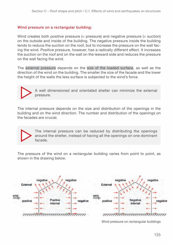
135
wind pressure on a rectangular building:
Wind creates both positive pressure (= pressure) and negative pressure (= suction) on the outside and inside of the building. The negative pressure inside the building tends to reduce the suction on the roof, but to increase the pressure on the wall fac-ing the wind. Positive pressure, however, has a radically different effect. It increases the suction on the roof and on the wall on the leeward side and reduces the pressure on the wall facing the wind.
the external pressure depends on the size of the loaded surface, as well as the direction of the wind on the building. The smaller the size of the facade and the lower the height of the walls the less surface is subjected to the wind’s force.
The internal pressure depends on the size and distribution of the openings in the building and on the wind direction. The number and distribution of the openings on the facades are crucial.
The pressure of the wind on a rectangular building varies from point to point, as shown in the drawing below.
Section C – Roof shape and pitch / C.1. Effects of wind and earthquakes on structures
A well dimensioned and orientated shelter can minimize the external pressure.
The internal pressure can be reduced by distributing the openings around the shelter, instead of having all the openings on one dominant facade.
Wind pressure on rectangular buildings

136
Section C – Roof shape and pitch / C.2. Wind pressure on walls
In reality the forces that will affect the shelter are an unpredictable combination of internal and external pressure and both should be fully considered in the calculations to dimension the elements of the roof in order to ensure its resistance to any given loading scenario.
c 2. wind preSSure on wAllS for different Shelter configurAtionS
This chapter shows how the walls of a shelter are subject to wind pressure and their influence on the wind pressure on roofs.
As shown in the diagrams of wind pressure on the shelter in the previous chapter, to calculate the wind pressure on the roof, it is necessary to know the wind pressure on the walls.
Wind pressure on the walls depends mainly on the permeability of the walls, that is to say the composition and the material of the wall cladding, the number of openings and their location.
c 2.1. wind preSSure on wAllS
The windward surfaces of the walls are subjected to pressure (positive pressure) while the leeward surfaces are subjected to suction (negative pressure). The pressure and suction vary from one side to the other, and depend mainly on the wind speed and locations of the openings.
the pressure of suction can be 2.5 times greater in the corners of the building than in the central part of the walls.
wind pressure on a "closed" shelter
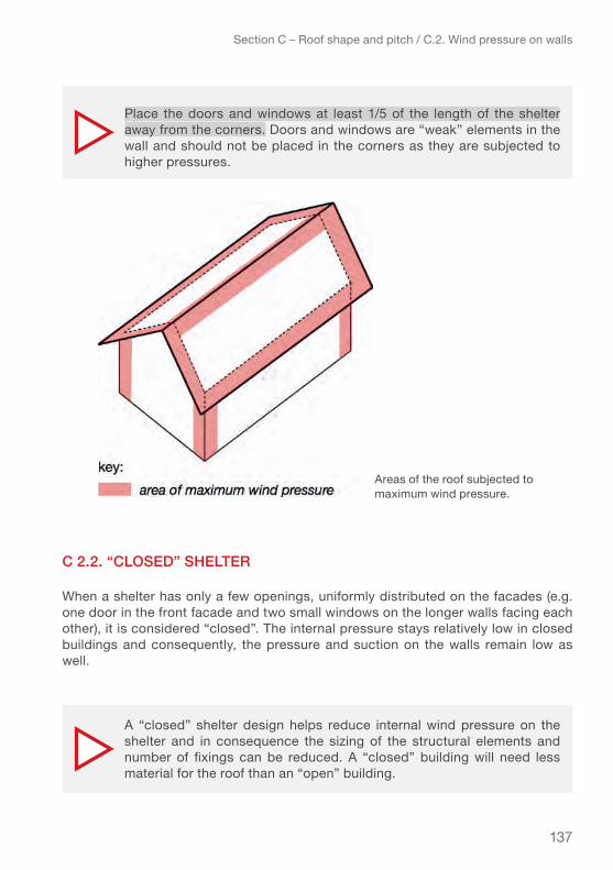
137
Section C – Roof shape and pitch / C.2. Wind pressure on walls
c 2.2. “cloSed” Shelter
When a shelter has only a few openings, uniformly distributed on the facades (e.g. one door in the front facade and two small windows on the longer walls facing each other), it is considered “closed”. The internal pressure stays relatively low in closed buildings and consequently, the pressure and suction on the walls remain low as well.
Place the doors and windows at least 1/5 of the length of the shelter away from the corners. Doors and windows are “weak” elements in the wall and should not be placed in the corners as they are subjected to higher pressures.
A “closed” shelter design helps reduce internal wind pressure on the shelter and in consequence the sizing of the structural elements and number of fixings can be reduced. A “closed” building will need less material for the roof than an “open” building.
Areas of the roof subjected to maximum wind pressure.
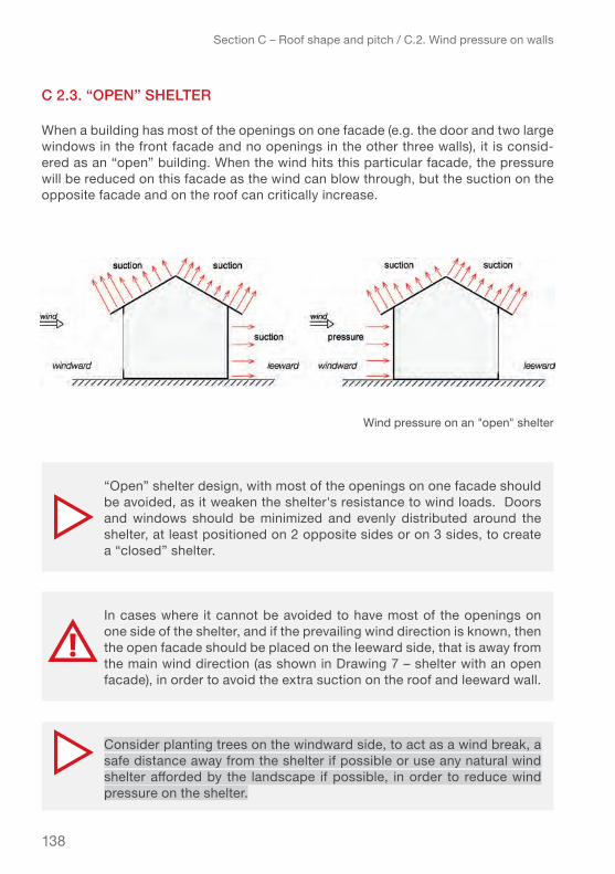
138
Section C – Roof shape and pitch / C.2. Wind pressure on walls
c 2.3. “open” Shelter
When a building has most of the openings on one facade (e.g. the door and two large windows in the front facade and no openings in the other three walls), it is consid-ered as an “open” building. When the wind hits this particular facade, the pressure will be reduced on this facade as the wind can blow through, but the suction on the opposite facade and on the roof can critically increase.
“Open” shelter design, with most of the openings on one facade should be avoided, as it weaken the shelter's resistance to wind loads. Doors and windows should be minimized and evenly distributed around the shelter, at least positioned on 2 opposite sides or on 3 sides, to create a “closed” shelter.
Consider planting trees on the windward side, to act as a wind break, a safe distance away from the shelter if possible or use any natural wind shelter afforded by the landscape if possible, in order to reduce wind pressure on the shelter.
In cases where it cannot be avoided to have most of the openings on one side of the shelter, and if the prevailing wind direction is known, then the open facade should be placed on the leeward side, that is away from the main wind direction (as shown in Drawing 7 – shelter with an open facade), in order to avoid the extra suction on the roof and leeward wall.
Wind pressure on an "open" shelter

139
Section C – Roof shape and pitch / C.2. Wind pressure on walls
c.2.4. Shelter elevAted from the ground
For shelters elevated from the ground, if the elevation is inferior to the height of the shelter (less than one storey) and if the ratio length/width of the shelter is in a range below 2.5 (e.g. ratio = length (6 m) / width (3 m) = 2) the wind pressure on the walls (windward, leeward and gable) stays the same as for a shelter on the ground.
the wind pressure on the roof stays the same as well. However, the floor is subjected to suction, which is equal to the maximum pressure applied on the windward wall.
Shelter with an open facade - wrong and right
wind pressure on an elevated shelter

140
Section C – Roof shape and pitch / C.3. Impact of wind pressure on different types of roofs
c 3. impAct of wind preSSure on different tYpeS of roofS
To understand which roof shape is the most resistant to strong winds, engineering calculations of the following four types of roofs were analysed and compared:
the dimensions of the structural elements of the walls and roof remain identical to the one calculated for a shelter sitting on the ground. However, the floor needs to be dimensioned by taking into consideration the negative wind pressure (suction) as well as the other usual loads.
If the shape of the shelter is elongated (ratio length /width > 2.5) and/or if it is elevated about its own height, then the wind pressure can be completely different and specific calculations will be required.
Four types of roofs

141
Section C – Roof shape and pitch / C.3. Impact of wind pressure on different types of roofs
each roof shape was calculated with both windward and leeward surfaces of the roof subjected to suction. The suction is composed of a vertical force which is "pulling" the roof off the structure (uplift effect), and a horizontal force which is "pushing" the roof off the structure. This “pushing” effect increases with increasing angle of pitch.
The combined forces of suction (pulling) and pressure (pushing) that cause the uplift effect on the roof vary on each surface from the eaves overhang to the ridge, and depend on:
1. the wind speed/cyclone category2. the exposure or type of terrain where the shelter is located 3. the orientation of the shelter 4. the roof shape 5. the pitch, of the roof
These five parameters and their influence are explained in the following chapters.
c 3.1. cYclone cAtegorieS And SuStAined wind Speed1
Tropical cyclones are classified into three main groups, based on their intensity: tropical depressions, tropical storms, and a third group of more intense storms, with sustained winds of at least 34 m/s or 119 km/h, with different names depending on the region of the world. A tropical storm in the North-western Pacific that reaches this speed is referred to as a typhoon; in the Northeast Pacific Basin, or in the North Atlantic, the same will be called a hurricane whereas in the Southern Hemisphere and the Indian Ocean the terms used are tropical cyclones, severe tropical cyclones or very intense tropical cyclones.
The responsible Regional Meteorological Centres use different scales to classify cyclones (or hurricanes or typhoons) but there are only a few variations between these classification systems. The two most common are the Beaufort Scale where winds of more than 119 km/h are classified from 12 to 16, and the Saffir–Simpson Hurricane Scale which uses categories 1 to 5 for the classification. The Category 1 in the Saffir-Simpson scale corresponds to Beaufort scale 12 (see Annex 3 for Beauford scale). The scale used as reference in this manual (and for the engineering calcula-tions) is the Saffir–Simpson hurricane wind scale. For further reference, the Beauford scale is included in Annex 3.
1 Source: Nation Weather Service – National Hurricane Center – http://www.nhc.noaa.gov

142
Section C – Roof shape and pitch / C.3. Impact of wind pressure on different types of roofs
Table 33 – cyclone category and equivalence of wind speed according to Saffir-Simpson
Maximum sustained winds in the strongest tropical cyclones have been estimated at about 95 metres per second or 346 kilometres per hour!
cAtegoRy sustAineD winDs km/h sustAineD winDs mph sustAineD winDs m/s
Tropical Storm Lower than 119 km/h Lower than 74 mph Lower than 33 m/s
1 119–153 km/h 74–95 mph 33–42.5 m/s
2 154–177 km/h 96–110 mph 42.7–49 m/s
3 (major) 178–208 km/h 111–129 mph 49.4–57.8 m/s
4 (major) 209–251 km/h 130–156 mph 58–69.7 m/s
5 (super typhoon) 252 km/h or higher 157 mph or higher 70 m/s or
higher
To calculate wind pressure on a building an average maximum wind speed has to be assumed. According to Eurocode (and similarly in other codes) the 10-minute average wind speed, at 10 m above ground level in open country terrain, for a 50-year return period is suggested as the value to use as the basic wind speed for calculations.
As the occurring wind speeds differ across the regions, most countries have indications for average values of basic wind speed which are used as references in the local building codes and serve to calculate the expected wind pressure applied on buildings. See Annex 4 – basic wind speed in various countries which gives an overview of basic wind speeds for most countries that experience very high winds. You can use the table in Annex 4 to find the applicable wind speed (cyclone category) for your context.

143
Section C – Roof shape and pitch / C.3. Impact of wind pressure on different types of roofs
c 3.2. eXpoSure SituAtion or tYpe of terrAin
The exposure of the site where the shelter is built has a significant influence on the wind forces or “peak wind pressure” that might apply to the shelter. At the same sus-tained wind speed, the peak wind pressure in a built up urban area is approximately half as high as on an exposed site on the coast.
The following four categorized types of site exposure have been used for the calculations:
● uRBAn AReATerrain category IV: Area in which at least 15 % of the surface is covered with buildings and their average height exceeds 15 m.
● suBuRBAn AnD RuRAl AReAs with coveR of vegetAtion Terrain category III: Area with regular cover of veg-etation or buildings or with isolated obstacles with separations of maximum 20 obstacle heights (such as villages, suburban terrain, permanent forest).
● RuRAl AReA with low vegetAtion Terrain category II: Area with low vegetation such as grass and isolated obstacles (trees, buildings) with separations of at least 20 obstacle heights.
● coAstAl AReA Terrain category 0: Sea, coastal area exposed to the open sea.
the fundamental value of the basic wind speed or wind velocity is a value that changes over time. Particularly in recent years some regions have experienced stronger winds than in the 20 or 30 previous years so the 50 years return periods suggested by most codes for calculations have to be adjusted. National building codes often include mappings of average wind speed occurrences but might not be recently updated. Consult the meteorological office website for your area, to get the latest values.
1–4 © Eurocode 1
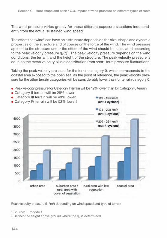
144
Section C – Roof shape and pitch / C.3. Impact of wind pressure on different types of roofs
The wind pressure varies greatly for those different exposure situations independ-ently from the actual sustained wind speed.
The effect that wind2 can have on a structure depends on the size, shape and dynamic properties of the structure and of course on the force of the wind. The wind pressure applied to the structure under the effect of the wind should be calculated according to the peak velocity pressure qp(z)3. The peak velocity pressure depends on the wind conditions, the terrain, and the height of the structure. The peak velocity pressure is equal to the mean velocity plus a contribution from short-term pressure fluctuations.
Taking the peak velocity pressure for the terrain category 0, which corresponds to the coastal area exposed to the open sea, as the point of reference, the peak velocity pres-sure for the other terrain categories will be considerably lower than for terrain category 0:
● Peak velocity pressure for Category I terrain will be 12% lower than for Category 0 terrain.● Category II terrain will be 28% lower● Category III terrain will be 49% lower● Category IV terrain will be 52% lower!
2 Source: Eurocode 13 Defines the height above ground where the qp is determined.
Peak velocity pressure (N / m2) depending on wind speed and type of terrain
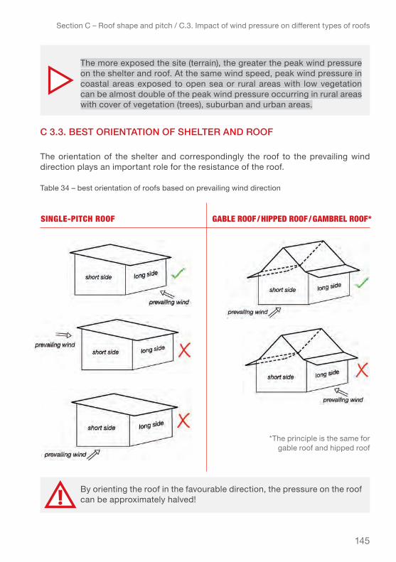
145
Section C – Roof shape and pitch / C.3. Impact of wind pressure on different types of roofs
c 3.3. beSt orientAtion of Shelter And roof
The orientation of the shelter and correspondingly the roof to the prevailing wind direction plays an important role for the resistance of the roof.
Table 34 – best orientation of roofs based on prevailing wind direction
The more exposed the site (terrain), the greater the peak wind pressure on the shelter and roof. At the same wind speed, peak wind pressure in coastal areas exposed to open sea or rural areas with low vegetation can be almost double of the peak wind pressure occurring in rural areas with cover of vegetation (trees), suburban and urban areas.
By orienting the roof in the favourable direction, the pressure on the roof can be approximately halved!
single-Pitch Roof gABle Roof / hiPPeD Roof / gAmBRel Roof*
*the principle is the same for gable roof and hipped roof
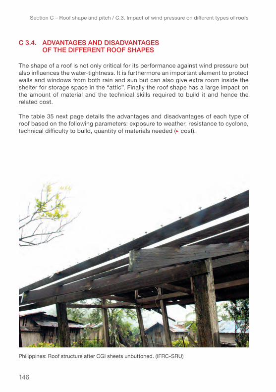
146
Section C – Roof shape and pitch / C.3. Impact of wind pressure on different types of roofs
c 3.4. AdvAntAgeS And diSAdvAntAgeS of the different roof ShApeS
The shape of a roof is not only critical for its performance against wind pressure but also influences the water-tightness. It is furthermore an important element to protect walls and windows from both rain and sun but can also give extra room inside the shelter for storage space in the “attic”. Finally the roof shape has a large impact on the amount of material and the technical skills required to build it and hence the related cost.
The table 35 next page details the advantages and disadvantages of each type of roof based on the following parameters: exposure to weather, resistance to cyclone, technical difficulty to build, quantity of materials needed (▹ cost).
Philippines: Roof structure after CGI sheets unbuttoned. (IFRC-SRU)

147
Section C – Roof shape and pitch / C.3. Impact of wind pressure on different types of roofs
tYpeS of roof + AdvAntAgeS – diSAdvAntAgeS
single-Pitch Roof
+ Only one slope ▹ less material required+ Easy shape to build+ low cost
– low protection from the rain and sun on the high wall– One large surface to cover ▹ high wind pressure– Low resistance to cyclones especially in coastal and rural areas with low vegetation– Can resist up to a category-3 cyclone, in urban area
gABle Roof + Main facades are protected from the rain and sun+ best compromise between technical difficulty, resistance to the wind and cost (can resist up to a category-4 cyclone in coastal area)
– Gable ends are exposed to the wind and rain– Requires more material than single-pitch roof ▹ more costly than single-pitch roof
hiPPeD Roof + walls are better protected from the rain and the sun+ Small covered surfaces ▹ less pressure+ Absence of verge+ Best shape to resist strong winds (can resist category-5 cyclone)
– Requires more material than gable roof– More costly than gable roof– Most technically complicated to build ▹ requires skilled builders
gAmBRel Roof
+ Main facades are protected from the rain and sun+ Provides living or storage space in the attic
– Gable ends are exposed to the wind and rain– Not recommended in areas exposed to strong winds (can resist up to a category-4 cyclone in urban and suburban areas)– Requires more material than gable roof ▹ more costly than gable roof– Technically complicated to build ▹ requires skilled builders
Table 35 – advantages and disadvantages of each type of roof

148
Section C – Roof shape and pitch / C.3. Impact of wind pressure on different types of roofs
c 3.5. pitch of the roof
The pitch of a roof is the decisive factor to ensure water tightness of the roof. The choice of the pitch of the roof depends mainly on the type of roofing materials used and the expected exposure to wind and rain in the area.
The case studies have been calculated for the four roof shapes with pitches of 5°, 15°, 30° and 45° to compare the resistance of the different roof types with the differ-ent pitches to wind pressure as well as their water tightness.
The table below presents a summary of the advantages and disadvantages of these 4 pitches. More detailed information about the choice of pitch, based on wind speed and areas to build, is provided in chapter C.4.
Table 36 – advantages and disadvantages of each pitch
pitch + AdvAntAgeS – diSAdvAntAgeS
5° pitch (9%)
+ Minimum material required+ Minimum cost+ Best angle for a single-pitch roof to resist wind pressure + Easy to walk on the roof
– CGI sheet roofing with this slope will not resist in cyclone-prone areas– Necessary to add sealing supplements at overlapping (crosswise) of the CGI sheets in order to provide proper rain proofing– Overlapping lengthwise should be avoided
15° pitch(26%)
+ Efficient material use+ Low cost (slightly costlier than 5° pitch)+ Best angle for gable and hipped roofs to resist wind pressure + Easy to walk on the roof
– Necessary to ensure proper overlapping of the CGI sheets to provide proper rain proofing
30° pitch(58%)
+ Good rain proofing+ Good angle for gable and hipped roofs to resist wind pressure
– Rather difficult to walk on the roof ▹ increase the safety measures during construction– Requires more material– More costly than 15° pitch
45° pitch(100%)
+ Best for rain proofing+ not ideal for wind resistance
– Difficult to walk on the roof ▹ necessary to increase the safety measures during construction– Requires more material– More costly than 30° pitch

149
Section C – Roof shape and pitch / C.3. Impact of wind pressure on different types of roofs
CGI sheeting roofs can have an angle between 5° (9%) and 45° (100%) depending on what is the prioritized use and necessary performance. Lower pitched roofs are generally more resistant to wind but more difficult to ensure the water tightness.
The higher the pitch, the higher the amount of material used and the more difficult to build.
The best compromise will depend on the weather situation of the context and the available resources.
For a roof with a pitch of less than 15 °, extra sealing supplements are recommended and increase overlapping crosswise of the CGI sheets while avoiding overlapping lengthwise.
Using profiled sheets (ribbed) can also be a solution. When using profiled sheets with ribs between 25 and 35 mm, the roof pitch can be reduced to 8.5° (15%) in exposed areas (strong winds and rain) and to 4° (7%) in other areas
Explanations on how to build a pitch are provided in Annex 6 – pitch of the roof in degrees, percentage and dimensions.
“sPeciAl cAse”: single-Pitch
The pitch of the roof plays a critical role in the dimensioning of the roofing elements, partic-ularly the connection between the rafters and the wall plate.
The higher the pitch, the stronger the horizontal forces on the supports. This has little impact on gable or hipped roof as these roofs, have a symmetrical structure. Consequently the loads will be distributed almost symmetrically and the horizontal force stays low.
However, for a single-pitch roof , as the structure is not symmetrical, the horizontal force increases significantly when the pitch increases. As hurricane straps are usu-ally not designed to resist great horizontal forces providing safe anchoring for roof structure becomes difficult.
To ensure good water tightness of a CGI roof roofing, a pitch of minimum 15° (26%) is recommended except for the single pitch roof (see special case of single pitch roof on following page).
Single-pitch roof with a 5° pitch

150
Section C – Roof shape and pitch / C.3. Impact of wind pressure on different types of roofs
c 3.6. roof detAilSIt is important to note, that the weakest parts of a roof structure like the eaves overhang, verges, hip angles and ridges are subjected to increased wind pressure regardless of the roof shape.
The drawings below shows in red the areas of maximum wind pressure on the 4 roof shapes.
It is therefore important to employ constructive measures to secure verge and eave overhangs.
veRge
The suction along the verge is higher than on the eaves over-hang and the rest of the roof. In consequence, the verges need to resist the highest forces.
A 5° pitch is the best angle for a single-pitch roof to resist wind pressure, but the water tightness of the roof will be challenged. To ensure the water tightness of the roof covering, the CGI sheet overlapping should be increased, as explained in Chapter D – Installation guidelines. Using profiled sheets with ribs between 25 mm and 35 mm can also be a solution.
For single-pitch roof, the pitch should remain low, and not exceed 15°.
Area of maximum wind pressure on each of the four types of roofs

151
Section C – Roof shape and pitch / C.3. Impact of wind pressure on different types of roofs
The choice of a short or a long verge will depend on various factors such as the local climate and cultural preferences, the cladding materials of the walls and the basic wind speed in the area where the shelter is located.
The table below summarizes the main advantages and disadvantages of short and long verges to help decide what kind of verge is most adequate for the shelter in a given context.
Table 37 – advantages and disadvantages of short and long verges
The wind pressure on the verge can be up to 3 times higher than on the other edges of the roof. Reducing the length of the verge will decrease the bending moment at the support, where the ridge beam is connected to the gable end and so make the roof more resistant to the wind forces.
To minimize the bending moment at the support (where the ridge beam is connected to the gable end). The maximum length of the verge should be less than 25 % of the distance between the trusses.
eXAmPles: ● Shelter size: 3 x 6 m with a gable roof, distance between trusses = 2.00 m ▹ the
verge should be < 50 cm (maximum verge = 0.25 x 2.00 = 0.50 m)● Shelter size: 3 x 6 m with a gable roof, distance between trusses = 3.00 m ▹ the
verge should be < 75 cm (maximum verge = 0.25 x 3.00 = 0.75 m)
▹ A gable roof with a 20 cm eaves overhang and verge can resist a category-3 cyclone, while the same roof with no verge (verge = 0 cm) can resist a category-4 cyclone.
+ AdvAntAgeS – diSAdvAntAgeS
no veRge + Reduces significantly the uplift effect on the roof
– Provides no protection for the walls from rain and sun
shoRt veRge + Reduces the uplift effect on the roof
– Provides little protection for the walls
long veRge + Provides protection of the walls from the rain and sun + Provide shade
– Increases significantly the uplift effect on the roof
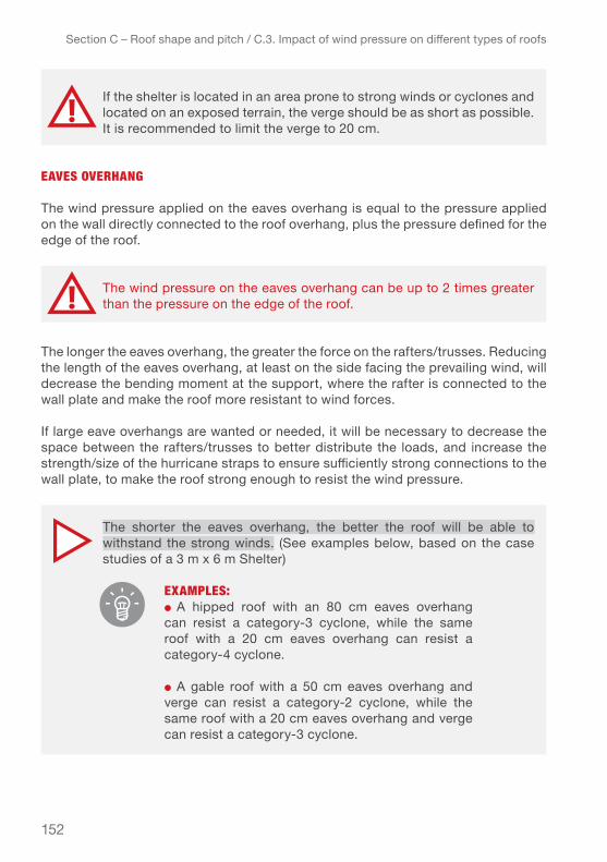
152
Section C – Roof shape and pitch / C.3. Impact of wind pressure on different types of roofs
eAves oveRhAng
The wind pressure applied on the eaves overhang is equal to the pressure applied on the wall directly connected to the roof overhang, plus the pressure defined for the edge of the roof.
The longer the eaves overhang, the greater the force on the rafters/trusses. Reducing the length of the eaves overhang, at least on the side facing the prevailing wind, will decrease the bending moment at the support, where the rafter is connected to the wall plate and make the roof more resistant to wind forces.
If large eave overhangs are wanted or needed, it will be necessary to decrease the space between the rafters/trusses to better distribute the loads, and increase the strength/size of the hurricane straps to ensure sufficiently strong connections to the wall plate, to make the roof strong enough to resist the wind pressure.
If the shelter is located in an area prone to strong winds or cyclones and located on an exposed terrain, the verge should be as short as possible. It is recommended to limit the verge to 20 cm.
The wind pressure on the eaves overhang can be up to 2 times greater than the pressure on the edge of the roof.
The shorter the eaves overhang, the better the roof will be able to withstand the strong winds. (See examples below, based on the case studies of a 3 m x 6 m Shelter)
eXAmPles:● A hipped roof with an 80 cm eaves overhang can resist a category-3 cyclone, while the same roof with a 20 cm eaves overhang can resist a category-4 cyclone.
● A gable roof with a 50 cm eaves overhang and verge can resist a category-2 cyclone, while the same roof with a 20 cm eaves overhang and verge can resist a category-3 cyclone.
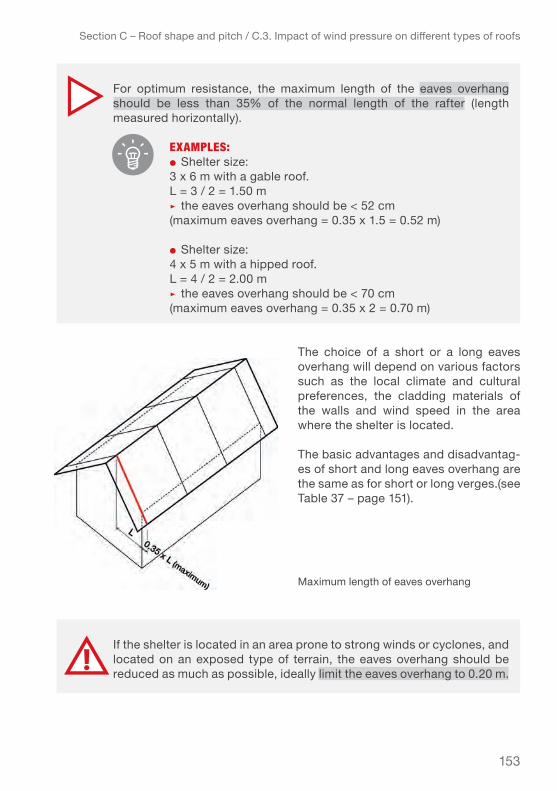
153
Section C – Roof shape and pitch / C.3. Impact of wind pressure on different types of roofs
The choice of a short or a long eaves overhang will depend on various factors such as the local climate and cultural preferences, the cladding materials of the walls and wind speed in the area where the shelter is located.
The basic advantages and disadvantag-es of short and long eaves overhang are the same as for short or long verges.(see Table 37 – page 151).
For optimum resistance, the maximum length of the eaves overhang should be less than 35% of the normal length of the rafter (length measured horizontally).
eXAmPles:● Shelter size: 3 x 6 m with a gable roof. L = 3 / 2 = 1.50 m▹ the eaves overhang should be < 52 cm (maximum eaves overhang = 0.35 x 1.5 = 0.52 m)
● Shelter size: 4 x 5 m with a hipped roof.L = 4 / 2 = 2.00 m▹ the eaves overhang should be < 70 cm (maximum eaves overhang = 0.35 x 2 = 0.70 m)
If the shelter is located in an area prone to strong winds or cyclones, and located on an exposed type of terrain, the eaves overhang should be reduced as much as possible, ideally limit the eaves overhang to 0.20 m.
Maximum length of eaves overhang

154
Section C – Roof shape and pitch / C.3. Impact of wind pressure on different types of roofs
PossiBle meAsuRes to secuRe long eAves oveRhAng if such ARe neeDeD to PRotect the wAlls fRom the weAtheR:
If long eave overhangs are necessary or required to protect the walls from rain (e.g. walls made of earth or other materials with low resistance to water), measures can be taken to ensure the strength of the roof. They will require special attention during the planning and implementation process and might also be more costly.
The eave brackets need to be well anchored either to the wall structure or in the ground through an isolated foundation or earth anchors. In both cases, calculations should determine the type of anchoring needed based on the wind pressure.
If resources allow, building a veranda all around the shelter with a roof separated from the main roof provides several benefits. The main roof should have short eaves and verges to not be subjected to additional wind pressure that put at risk the whole roof. At the same time the veranda roof will protect the walls against bad weather and offer a covered, shaded space. Even if the veranda roof may be lifted or damaged by a cyclone the main roof should remain safely on the shelter/house.
Build the long eaves overhang on the leeward side and a short one on the windward side (facing the prevailing wind) as shown in the drawing below. This solution should not be implemented in areas prone to strong winds.
If the walls need protection from the weather, keep in place the long eaves overhang and place an eaves bracket at the end of each rafter to provide additional support to hold the roof in place under the wind pressure.
Short and long eaves overhang – incorrect and correct
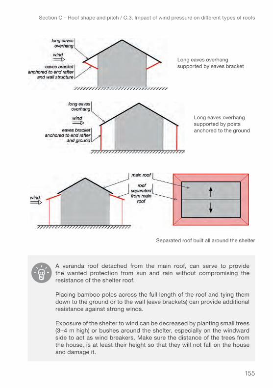
155
Section C – Roof shape and pitch / C.3. Impact of wind pressure on different types of roofs
A veranda roof detached from the main roof, can serve to provide the wanted protection from sun and rain without compromising the resistance of the shelter roof.
Placing bamboo poles across the full length of the roof and tying them down to the ground or to the wall (eave brackets) can provide additional resistance against strong winds.
Exposure of the shelter to wind can be decreased by planting small trees (3–4 m high) or bushes around the shelter, especially on the windward side to act as wind breakers. Make sure the distance of the trees from the house, is at least their height so that they will not fall on the house and damage it.
Long eaves overhang supported by eaves bracket
Long eaves overhang supported by posts anchored to the ground
Separated roof built all around the shelter
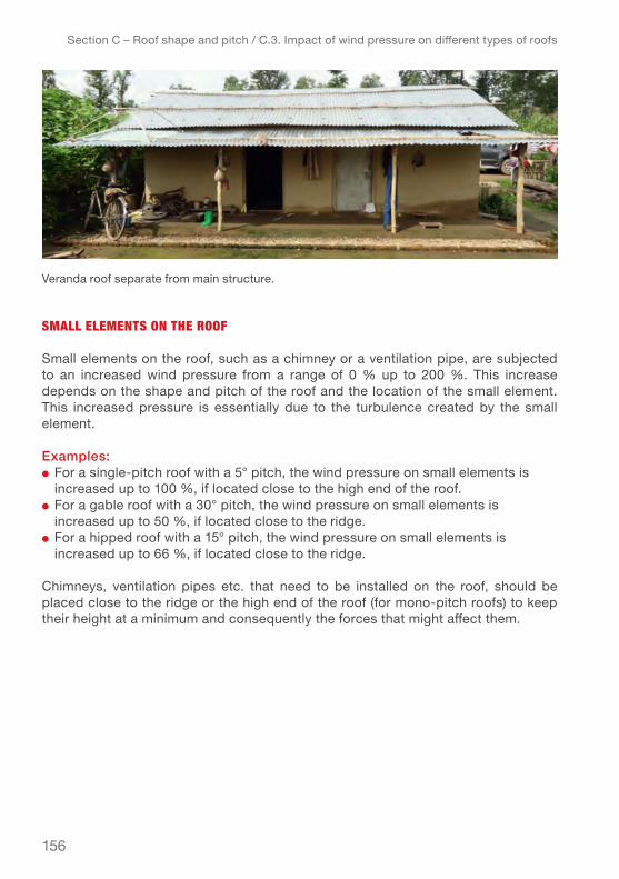
156
Section C – Roof shape and pitch / C.3. Impact of wind pressure on different types of roofs
smAll elements on the Roof
Small elements on the roof, such as a chimney or a ventilation pipe, are subjected to an increased wind pressure from a range of 0 % up to 200 %. This increase depends on the shape and pitch of the roof and the location of the small element. This increased pressure is essentially due to the turbulence created by the small element.
examples:● For a single-pitch roof with a 5° pitch, the wind pressure on small elements is
increased up to 100 %, if located close to the high end of the roof.● For a gable roof with a 30° pitch, the wind pressure on small elements is
increased up to 50 %, if located close to the ridge.● For a hipped roof with a 15° pitch, the wind pressure on small elements is
increased up to 66 %, if located close to the ridge.
Chimneys, ventilation pipes etc. that need to be installed on the roof, should be placed close to the ridge or the high end of the roof (for mono-pitch roofs) to keep their height at a minimum and consequently the forces that might affect them.
Veranda roof separate from main structure.

157
Section C – Roof shape and pitch / C 4. Roof choices depending on exposure and wind speed
c 4. choice of roof ShApe And pitch depending on the eXpoSure SituAtion And wind Speed
The first important factor for the design of a shelter and particularly for the choice of the most adequate roof shape and pitch is the surrounding context or type of terrain and exposure, that the shelter will have to perform in.
This chapter provides a comprehensive overview of the performance of different roof shapes in different exposure situations and subjected to different wind speeds.
The information provided is based on the case study and calculations of a “closed” shelter model (openings well distributed on 3 sides) of 3 x 6 m, with eaves and verge overhang of 45 cm, elevation from the ground of 75 cm (total height of the ridge: 4 m). For the calculations of the roof resistance all roof types were calculated assuming a roof construction with the following materials:
● RAfteRs: 38 x 89 mm / 2” x 4”
● lAths: 38 x 64 mm / 2” x 3”
● thickness of the cgi sheet: 26 gauge / 0.551 mm
● tyPe of fiXings / fAsteneRs: roofing nails smooth-shank (diameter = 4.11 mm), roofing nails twisted-shank (3.76 mm) and roofing screws (4.17 mm), length = 63 mm (2½”), as required to resist the different winds-speeds.
● PenetRAtion DePth of the fiXing / fAsteneR: 38 mm
The distances between rafters and laths as well as the amount of fixings/fasteners were adjusted in function of the required performance of the roof structure to resist the assumed wind pressure in the given type of terrain.
● Distance between the rafters (varies from 1.20 to 0.30 m)● Distance between the laths (varies from 0.60 to 0.30 m)
The calculations have been made based on the specifications of 26 gauge / 0.551 mm CGI sheets. If you are looking to reach the same resistance with thinner sheets, you will need to increase the number of supporting laths as well as the fasteners and consider to using extra washers depending on the exposure of the site.

158
Section C – Roof shape and pitch / C 4. Roof choices depending on exposure and wind speed
The below tables give basic indications for the resistance of each type of roof in the four types of generic “typical” site exposure4, from low to very high exposure:
● terrain category iv: urban area with high buildings● terrain category iii: suburban area or rural area with cover of vegetation● terrain category ii: rural area with low vegetation● terrain category 0: coastal area exposed to the open sea
For each type of terrain the resistance of the roof has been calculated for six differ-ent wind-speeds5, tropical storm and cyclone categories 1, 2, 3, 4 and 5. The roofs are then compared for each exposure situation with regard to the following criteria:
4 Based on Eurocode 15 Based on the Simpson-Saffir scale (see Annex 3 – Cyclone categories and sustained wind speed)
The choice of the roof shape and pitch in this study is uniquely based on the effects of winds (wind pressure). Snow loads have not been considered. Consequently, this study is not valid in the regions where snow is present and considered as a predominant factor in the calculation of structural elements.
Philippines: Shelter model used as base for the calculations. (IFRC-SRU)

159
● the Pitch for the given roof shape as it has i mplications on the stability / wind resistance, ease of construction as well as on the quantity of materials needed.
● Technicality, or RequiReD skill level to build this shape, as it directly affects implementation time and quality: basic, average, advanced.
● quAntity of mAteRiAl required as it has direct consequences on logistics and cost: very low, low, average, high, very high, excessive.
● Recommended type of fiXings / fAsteneRs as this is critical to ensure the Cgi sheets are well secured to resist the assumed wind-pressure and has a direct implication on cost and installation time(price and number of fixings): roofing nails (smooth-shank and twisted-shank) or roofing screws6.
c.4.1. urbAn AreA
6 More detailed information on number of fasteners to use and spacing between laths and rafters in Section D
Section C – Roof shape and pitch / C 4. Roof choices depending on exposure and wind speed
wind speed< 119 km/h(tropical storm)
single-Pitch Roof
gABle Roof
hiPPeD Roof
gAmBRel Roof
pitch 5° ≤ pitch ≤ 15° 5° ≤ pitch ≤ 45° 5° ≤ pitch ≤ 45° bottom pitch = 15°top pitch = 45°
required skills basic average advanced advanced
material quantity/cost
low – average average average average
fixings / fasteners
Roofing nails, smooth-shank can be used but will require around double the quantity to reach the same resistance as with than twisted-shank nails. With roofing screws you will need about half the quantity than for twisted shank nails (slight variations depending on the type of roof). The roof estimate form in ANNEX-7 can be used to check which type of fas-tener is the most efficient to use in your particular case.
Table 38 – most appropriate roof shapes and pitches for urban areas
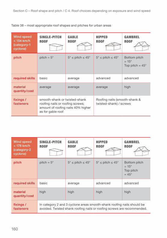
160
Section C – Roof shape and pitch / C 4. Roof choices depending on exposure and wind speed
Table 38 – most appropriate roof shapes and pitches for urban areas
wind speed < 178 km/h (category-2 cyclone)
single-Pitch Roof
gABle Roof
hiPPeD Roof
gAmBRel Roof
pitch pitch = 5° 5° ≤ pitch ≤ 45° 5° ≤ pitch ≤ 45° bottom pitch = 15°top pitch = 45°
required skills basic average advanced advanced
material quantity/cost
high high high high
fixings / fasteners
In category 2 and 3 cyclone areas smooth-shank roofing nails should be avoided. Twisted shank roofing nails or roofing screws are recommended.
wind speed< 154 km/h(category-1 cyclone)
single-Pitch Roof
gABle Roof
hiPPeD Roof
gAmBRel Roof
pitch pitch = 5° 5° ≤ pitch ≤ 45° 5° ≤ pitch ≤ 45° bottom pitch = 15°Top pitch = 45°
required skills basic average advanced advanced
material quantity/cost
average average average high
fixings / fasteners
smooth-shank or twisted-shank roofing nails or roofing screws; amount of roofing nails 40% higher as for gable roof
Roofing nails (smooth-shank & twisted-shank) / screws

161
Section C – Roof shape and pitch / C 4. Roof choices depending on exposure and wind speed
wind speed< 209 km/h(category-3 cyclone)
single-Pitch Roof
gABle Roof
hiPPeD Roof
gAmBRel Roof
pitch pitch = 5° 5° ≤ pitch ≤ 45°best cost-performance ratio at a pitch of 15°
5°≤ pitch ≤ 45° bottom pitch = 15°Top pitch = 45°
required skills basic average high advanced
material quantity/cost
very high very high high very high *
fixings / fasteners
Roofing screws In category 2 and 3 cyclone areas smooth-shank recommended roofing nails should be avoided. Twisted shank roofing nails or roofig screws are recommended.
wind speed< 252 km/h(category-4 cyclone)
single-Pitch Roof
gABle Roof
hiPPeD Roof
gAmBRel Roof
pitch Can not resist category 4 or higher cyclone.
5° ≤ pitch ≤ 45° with eaves overhang = 30 cm and verge = 30 cm
5°≤ pitch ≤ 45° bottom pitch = 15°Top pitch = 45°with verge = 0 cm
required skills average high advanced
material quantity/cost
very high high very high
fixings / fasteners
Roofing screws recommended
* Very large quantity of material ▹ very costly
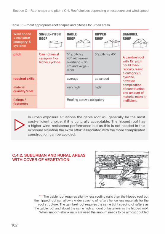
162
c.4.2. SuburbAn And rurAl AreAS with cover of vegetAtion
Section C – Roof shape and pitch / C 4. Roof choices depending on exposure and wind speed
Table 38 – most appropriate roof shapes and pitches for urban areas
*** The gable roof requires slightly less roofing nails than the hipped roof but the hipped roof can allow a wider spacing of rafters hence less materials for the
roof structure. The gambrel roof requires the same tight spacing of rafters as the gable roof and about the same high amount of fasteners as the hipped roof.
When smooth-shank nails are used the amount needs to be almost doubled
In urban exposure situations the gable roof will generally be the most cost-efficient choice, if it is culturally acceptable. The hipped roof has a higher wind-resistance performance but as this is not needed in this exposure situation the extra effort associated with the more complicated construction can be avoided.
wind speed< 280 km/h(category-5 cyclone)
single-Pitch Roof
gABle Roof
hiPPeD Roof
gAmBRel Roof
pitch Can not resist category 4 or higher cyclone.
5° ≤ pitch ≤ 45° with eaves overhang = 30 cm and verge = 0 cm
5°≤ pitch ≤ 45°A gambrel roof with 15° pitch could theo-retically resist a category 5 cyclone, however complication of construction and amount of material make it inefficient.
required skills average advanced
material quantity/cost
very high high
fixings / fasteners
Roofing screws obligatory
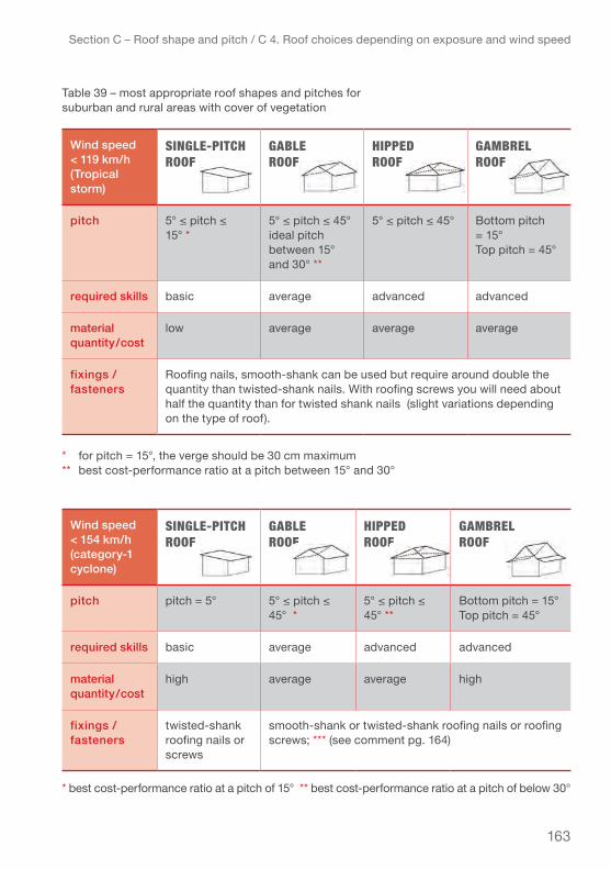
163
Section C – Roof shape and pitch / C 4. Roof choices depending on exposure and wind speed
Table 39 – most appropriate roof shapes and pitches for suburban and rural areas with cover of vegetation
* for pitch = 15°, the verge should be 30 cm maximum** best cost-performance ratio at a pitch between 15° and 30°
* best cost-performance ratio at a pitch of 15° ** best cost-performance ratio at a pitch of below 30°
wind speed< 119 km/h(tropical storm)
single-Pitch Roof
gABle Roof
hiPPeD Roof
gAmBRel Roof
pitch 5° ≤ pitch ≤ 15° *
5° ≤ pitch ≤ 45°ideal pitch between 15° and 30° **
5° ≤ pitch ≤ 45° bottom pitch = 15°Top pitch = 45°
required skills basic average advanced advanced
material quantity/cost
low average average average
fixings / fasteners
Roofing nails, smooth-shank can be used but require around double the quantity than twisted-shank nails. With roofing screws you will need about half the quantity than for twisted shank nails (slight variations depending on the type of roof).
wind speed< 154 km/h(category-1 cyclone)
single-Pitch Roof
gABle Roof
hiPPeD Roof
gAmBRel Roof
pitch pitch = 5° 5° ≤ pitch ≤ 45° *
5° ≤ pitch ≤ 45° **
Bottom pitch = 15°Top pitch = 45°
required skills basic average advanced advanced
material quantity/cost
high average average high
fixings / fasteners
twisted-shank roofing nails or screws
smooth-shank or twisted-shank roofing nails or roofing screws; *** (see comment pg. 164)

164
Section C – Roof shape and pitch / C 4. Roof choices depending on exposure and wind speed
Table 39 – for suburban and rural areas with cover of vegetation
* with eaves overhang max. 30 cm and verge = 0 cm ▹ very easy to build** ideal pitch 15° ▹ but not very practical to build
wind speed < 178 km/h (category-2 cyclone)
single-Pitch Roof
gABle Roof
hiPPeD Roof
gAmBRel Roof
pitch pitch = 5° 5° ≤ pitch ≤ 45°
pitch ≤ 30° Bottom pitch = 15°Top pitch = 45°
required skills basic average advanced advanced
material quantity/cost
very high very high high very high
fixings / fasteners
twisted-shank roofing nails / roofing screws recommended
wind speed< 209 km/h(category-3 cyclone)
single-Pitch Roof
gABle Roof
hiPPeD Roof
gAmBRel Roof
pitch pitch = 5° * 15° ≤ pitch ≤ 45°
pitch ≤ 30° Bottom pitch = 15°Top pitch = 45° **
required skills basic average advanced advanced
material quantity/cost
very high very high high very high
fixings / fasteners
roofing screws with large washers recommended
twisted-shank roofing nails or roofing screws
In suburban and rural areas with cover of vegetation both single pitch and gambrel roof are not recommended in areas where category 3 cyclones are experienced on a 50 year return period. To resist a category 3 cyclone and higher, a gable roof construction will require more the material for the roof structure than a hipped roof (spacing between rafters 0.45 m for gable roof and 0.60 m for hipped roof, same spacing ▹

165
Section C – Roof shape and pitch / C 4. Roof choices depending on exposure and wind speed
* with eaves overhang = 30 cm and verge = 0 cm; or pitch = 15° with eaves overhang = 20 cm and verge = 20 cm ** with verge = 0 cm *** not efficient to resist category-4 cyclones
wind speed< 252 km/h(category-4 cyclone)
single-Pitch Roof
gABle Roof
hiPPeD Roof
gAmBRel Roof
pitch Can not resist category 4 or higher cyclone.
15° ≤ pitch ≤ 45° *
pitch ≤ 30° bottom pitch = 15°Top pitch = 45° **
required skills average advanced advanced
material quantity/cost
very high very high excessive ***
fixings / fasteners
twisted-shank roofing nails or roofing screws (all with large washers)
Roofing screws recommended
wind speed< 280 km/h(category-5 cyclone)
single-Pitch Roof
gABle Roof
hiPPeD Roof
gAmBRel Roof
pitch Can not resist category 5 cyclone.
pitch = 15° with eaves overhang = 30 cm and verge = 0 cm
pitch ≤ 30°
the gambrel roof construction is not efficient to resist category-5 cyclones
required skills average advanced
material quantity/cost
excessive very high
fixings / fasteners
Roofing screws with large sealing washers
▹ for laths, 0.60 m; see chapter D for more details) hence a hipped roof might be the preferable choice under this exposure situation if it fits the cultural context.

166
c.4.3. rurAl AreA with low vegetAtion
Terrain category II: Area with low vegetation such as grass and isolated obstacles (trees, buildings) with sep-arations of at least 20 obstacle heights.
Section C – Roof shape and pitch / C 4. Roof choices depending on exposure and wind speed
wind speed< 119 km/h(tropical storm)
single-Pitch Roof
gABle Roof
hiPPeD Roof
gAmBRel Roof
pitch pitch = 5° 5° ≤ pitch ≤ 45° *
5° ≤ pitch ≤ 45° **
Bottom pitch = 15°Top pitch = 45°
required skills basic average advanced advanced
material quantity/cost
high average average high
fixings / fasteners
Roofing nails, smooth-shank can be used but require around double the quantity than twisted-shank nails. With roofing screws you will need about half the quantity than for twisted shank nails (slight variations depending on the type of roof).
Table 40 – most appropriate roof shapes and pitches for rural areas with low vegetation
* best cost-performance ratio at a pitch between 15° and 30°** best cost-performance ratio at a pitch of below 30°
Rural area with low vegetation
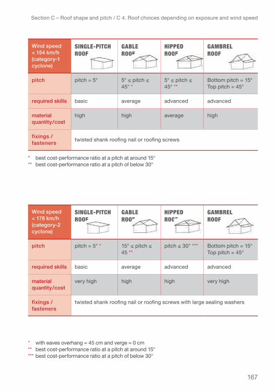
167
Section C – Roof shape and pitch / C 4. Roof choices depending on exposure and wind speed
wind speed < 178 km/h (category-2 cyclone)
single-Pitch Roof
gABle Roof
hiPPeD Roof
gAmBRel Roof
pitch pitch = 5° * 15° ≤ pitch ≤ 45 **
pitch ≤ 30° *** Bottom pitch = 15°Top pitch = 45°
required skills basic average advanced advanced
material quantity/cost
very high high high very high
fixings / fasteners
twisted shank roofing nail or roofing screws with large sealing washers
* best cost-performance ratio at a pitch at around 15° ** best cost-performance ratio at a pitch of below 30°
* with eaves overhang = 45 cm and verge = 0 cm ** best cost-performance ratio at a pitch at around 15° *** best cost-performance ratio at a pitch of below 30°
wind speed< 154 km/h(category-1 cyclone)
single-Pitch Roof
gABle Roof
hiPPeD Roof
gAmBRel Roof
pitch pitch = 5° 5° ≤ pitch ≤ 45° *
5° ≤ pitch ≤ 45° **
Bottom pitch = 15°Top pitch = 45°
required skills basic average advanced advanced
material quantity/cost
high high average high
fixings / fasteners twisted shank roofing nail or roofing screws

168
Section C – Roof shape and pitch / C 4. Roof choices depending on exposure and wind speed
* with eaves overhang = 20 cm verge = 20 cm ** with eaves overhang = 20 cm verge = 0 cm*** The gambrel roof construction is not efficient to resist category 3 cyclones.
* with eaves overhang = 20 cm and verge = 0 cm
Table 40 – most appropriate roof shapes and pitches for rural areas with low vegetation
wind speed< 209 km/h(category-3 cyclone)
single-Pitch Roof
gABle Roof
hiPPeD Roof
gAmBRel Roof
pitch Cannot resist category 3 or higher cyclone.
15° ≤ pitch ≤ 45 *
pitch ≤ 30° bottom pitch = 15°Top pitch = 45° **
required skills average advanced advanced
material quantity/cost
very high very high excessive ***
fixings / fasteners
roofing screws with large sealing washers recommended
wind speed< 252 km/h(category-4 cyclone)
single-Pitch Roof
gABle Roof
hiPPeD Roof
gAmBRel Roof
pitch Cannot resist category 4 cyclone.
15°≤ pitch ≤ 30° * pitch ≤ 30° Cannot resist category 4 cyclone.required skills average advanced
material quantity/cost
excessive very high
fixings / fasteners
Use roofing screws with large sealing washers – obligatory
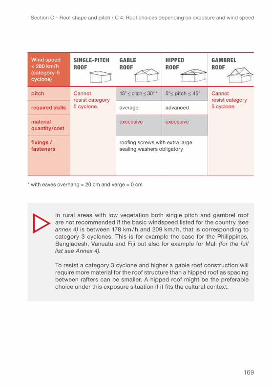
169
Section C – Roof shape and pitch / C 4. Roof choices depending on exposure and wind speed
* with eaves overhang = 20 cm and verge = 0 cm
wind speed< 280 km/h(category-5 cyclone)
single-Pitch Roof
gABle Roof
hiPPeD Roof
gAmBRel Roof
pitch Cannot resist category 5 cyclone.
15° ≤ pitch ≤ 30° * 5°≤ pitch ≤ 45° Cannot resist category 5 cyclone.required skills average advanced
material quantity/cost
excessive excessive
fixings / fasteners
roofing screws with extra large sealing washers obligatory
In rural areas with low vegetation both single pitch and gambrel roof are not recommended if the basic windspeed listed for the country (see annex 4) is between 178 km / h and 209 km / h, that is corresponding to category 3 cyclones. This is for example the case for the Philippines, Bangladesh, Vanuatu and Fiji but also for example for Mali (for the full list see Annex 4).
To resist a category 3 cyclone and higher a gable roof construction will require more material for the roof structure than a hipped roof as spacing between rafters can be smaller. A hipped roof might be the preferable choice under this exposure situation if it fits the cultural context.

170
c.4.4. coAStAl AreA
Terrain category 0: Sea, coastal area exposed to the open sea.
Section C – Roof shape and pitch / C 4. Roof choices depending on exposure and wind speed
wind speed< 119 km/h(tropical storm)
single-Pitch Roof
gABle Roof
hiPPeD Roof
gAmBRel Roof
pitch pitch = 5° 5° ≤ pitch ≤ 45° **
5° ≤ pitch ≤ 45° *
Bottom pitch = 15°Top pitch = 45°
required skills basic average advanced advanced
material quantity/cost
high average average high
fixings / fasteners
twisted shank roofing nail or roofing screws ***
wind speed< 154 km/h(category-1 cyclone)
single-Pitch Roof
gABle Roof
hiPPeD Roof
gAmBRel Roof
pitch pitch = 5° * 5° ≤ pitch ≤ 45°
5° ≤ pitch ≤ 30°
Bottom pitch = 15°Top pitch = 45°
required skills basic average advanced advanced
material quantity/cost
very high high average very high
fixings / fasteners
twisted shank roofing nail or roofing screws **
Table 41 – for coastal areas
* best cost-performance ratio at a pitch of below 30° **best cost-performance at a pitch of 15°*** Roofing nails, smooth-shank can be used but require around double the quantity than twisted-shank nails. With roofing screws you will need about half the quantity than for twisted shank nails (slight variations depending on the type of roof).
* with eaves overhang = 45 cm and verge = 0 cm

171
Section C – Roof shape and pitch / C 4. Roof choices depending on exposure and wind speed
* with eaves overhang = 20 cm and verge = 20 cm** with eaves overhang = 30 cm and verge = 0 cm
wind speed < 178 km/h (category-2 cyclone)
single-Pitch Roof
gABle Roof
hiPPeD Roof
gAmBRel Roof
pitch Cannot resist category 2 or higher cyclone.
5° ≤ pitch ≤ 45° *
5° ≤ pitch ≤ 30° bottom pitch = 15°Top pitch = 45° **
required skills average advanced advanced
material quantity/cost
very high high excessive
fixings / fasteners
roofing screws with large washers recommended
* with eaves overhang = 20 cm verge = 0 cm
wind speed< 209 km/h(category-3 cyclone)
single-Pitch Roof
gABle Roof
hiPPeD Roof
gAmBRel Roof
pitch Cannot resist category 3 cyclone.
5° ≤ pitch ≤ 45° *
5° ≤ pitch ≤ 30° Cannot resist category 3 cyclone.
required skills average advanced
material quantity/cost
excessive very high
fixings / fasteners
roofing screws with large sealing washers recommended

172
Section C – Roof shape and pitch / C 4. Roof choices depending on exposure and wind speed
* with eaves overhang = 20 cm verge = 0 cm** with eaves overhang = 20 cm (max.)
* with eaves overhang = 20 cm (max.)
wind speed< 252 km/h(category-4 cyclone)
single-Pitch Roof
gABle Roof
hiPPeD Roof
gAmBRel Roof
pitch Cannot resist category 4 cyclone.
15° ≤ pitch ≤ 30° *
5° ≤ pitch ≤ 30° **
Cannot resist category 4 cyclone.
required skills average advanced
material quantity/cost
excessive very high
fixings / fasteners
roofing screws with extra large sealing washers obligatory
wind speed< 280 km/h(category-5 cyclone)
single-Pitch Roof
gABle Roof
hiPPeD Roof
gAmBRel Roof
pitch Cannot resist category 5 cyclone.
Cannot resist category 5 cyclone.
5° ≤ pitch ≤ 30° *
Cannot resist category 5 cyclone.
required skills advanced
material quantity/cost
excessive
fixings / fasteners
roofing screws with extra large sealing washers obligatory
Table 41 – most appropriate roof shapes and pitches for coastal areas

173
Section C – Roof shape and pitch / C 4. Roof choices depending on exposure and wind speed
In exposed coastal (or open areas without any cover of vegetation) both single pitch and gambrel roof are not an efficient choice as they require larger amounts of materials to make them resistant to tropical storms.
Up to category 2 cyclones the gable roof is still the slightly less costly alternative. For category 3 and 4 cyclones the hipped roof will provide better performance at about the same price while for category 5 only the hipped roof can resist.
Ideally areas with such high exposure should be avoided. If it is not possible, the shelter model used for the case study calculations is not recommended for such areas. The roof structure needs to be stronger (larger diameters for rafters and laths), the CGI should be thicker and longer roofing screws and strong hurricane straps should be used.
Philippines: Skewed building after typhoon Haima, 2016. (see racking effect on p. 133). (IFRC-SRU)

174
Section C – Roof shape and pitch / Practical Summary
prActicAl SummArY – Section c
wind pressure on the walls of a shelter can also increase or decrease the wind pres-sure on the roof as a function of the height, dimensions and type of material of the walls. Therefore correct orientation, dimensioning and design of the shelter all contrib-ute to decrease the wind pressure on the shelter as a whole and the roof in particular. In exposed coastal locations the wind pressure affecting the shelter will be about double what the shelter would need to resist in a built up urban area.
The following basic design principles help minimize wind pressure on the walls and consequently on the roof:
● Design the shelter according to the exposure of the location and common wind speeds where the shelter will be built. Wind pressure on a shelter built in the coast-al or rural area with low vegetation is approximately 1.5 times higher than on one built in a suburban or rural area with a cover of vegetation (surrounded by trees)!
● Orient the shelter with the shorter side exposed to the main wind direction. With excep-tion of shelters with a shed/single-pitch roof, which are best oriented with the longer side of the shelter and the lower side of the roof towards the main wind direction.
● Dimension the shelter to keep the ratio length/width lower than 2 (e.g. length 5 m / width 3 m = 1,6 ratio).
● Avoid elevating the shelter more than its own height from the ground and keep the height of the shelter as low as reasonably possible.
● A “closed” shelter design with equally distributed openings helps reduce internal wind pressure. In consequence a “closed” building will be more wind-resistant.
● Place the doors and windows at least 1/5 of the length of the shelter away from the corners because wind pressure is highest there and the openings are weaker than walls.
● Keep the eaves overhang and verge short as wind pressure is the highest on the perimeter of the roof.
● To ensure water tightness of the CGI roof covering, it is recommended to have a pitch higher than 15°.
Apart from the wind resistance all types of roofs have different advantages and dis-advantages that should be considered when planning and designing a shelter.Cultural preferences, living practices and maintenance efforts are important criteria for the choice of roof. In order to assure a technically safe and functional roof the fol-lowing aspects are the most important:
1. exposure of terrain on which the shelter will be built2. basic wind speed at the shelter location (see Annex 4 – basic wind speed in various countries)3. water-tightness of the roof covering

175
Section C – Roof shape and pitch / Practical Summary
The table below summarizes the results of the study conducted on a “closed” model shelter – of 3 x 6 m (for details see chapter C.4. Choice of roof shape and pitch depending on the exposure situation and wind speed ) :
Table 42 – outcomes of the study – “closed” shelter
roof ShApe outcomeS
single-Pitch Roof
● Single-pitch roofs are the least resistant to wind pressure● Most efficient pitch: between 5–15°● For low pitches, waterproofing of the CGI sheet roof covering needs extra attention (as explained in chapter 3.5)● In urban, suburban or rural areas with cover of vegetation it can resist a category-3 cyclone● In rural areas with low vegetation, can resist a category-2 cyclone● In coastal areas, can resist a category-1 cyclone● Level of skill required for the construction is basic● Quantity of material and in consequence the cost is lowest
gABle Roof ● gable roofs are the second most resistant to wind pressure● Most efficient pitch: between 15–30°● Properly implemented this shape of roof can resist a category-5 cyclone (max. 280 km/h) in suburban or rural areas with cover of vegetation, as well as in rural areas with low vegetation.● In coastal areas, it can resist a category-4 cyclone● Level of skill required for the construction is average● Quantity of material and in consequence the cost is average
hiPPeD Roof ● Hipped roofs are the most resistant to wind pressure ● Most efficient pitch: between 15–30°● Properly implemented this shape of roof can resist a category-5 cyclone (max. 280 km / h) in all of the four generic exposure environments (Urban, suburban, rural, coastal)● Level of skill required for the construction is advanced● Quantity of material and in consequence the cost is comparably high
gAmBRel Roof ● gambrel roofs are the third most resistant to wind pressure● In urban suburban or rural areas with cover of vegetation it can resist a category-4 cyclone● In rural areas with low vegetation, can resist a category-3 cyclone● In coastal areas, can resist a category-2 cyclone● Level of skill required for the construction is advanced● Quantity of material and in consequence the cost is high
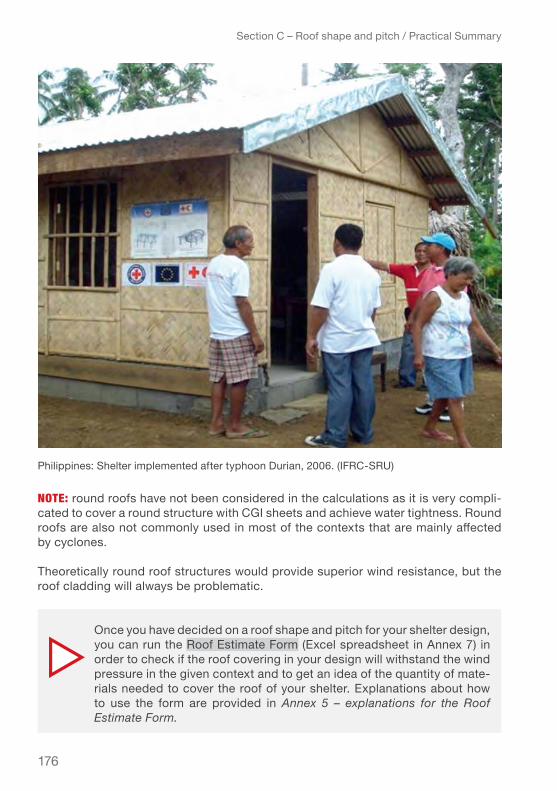
176
note: round roofs have not been considered in the calculations as it is very compli-cated to cover a round structure with CGI sheets and achieve water tightness. Round roofs are also not commonly used in most of the contexts that are mainly affected by cyclones.
Theoretically round roof structures would provide superior wind resistance, but the roof cladding will always be problematic.
Section C – Roof shape and pitch / Practical Summary
Once you have decided on a roof shape and pitch for your shelter design, you can run the Roof estimate form (Excel spreadsheet in Annex 7) in order to check if the roof covering in your design will withstand the wind pressure in the given context and to get an idea of the quantity of mate-rials needed to cover the roof of your shelter. Explanations about how to use the form are provided in Annex 5 – explanations for the Roof Estimate Form.
Philippines: Shelter implemented after typhoon Durian, 2006. (IFRC-SRU)

177
PRActicAl tiPs helP to secuRe the shelteR AnD Roof AgAinst stRong winDs:
Section C – Roof shape and pitch / Practical Summary
▹ Keep the windows and doors securely closed during a severe storm. Shutters provide an additional level of protection to windows and doors. Open doors or windows will cause the wind pressure to increase significantly inside the building and great damage can occur. See Chapter E – Roof maintenance and preventive measures for more information.
▹ If it is not possible to securely close the doors and the windows, the next best solution is to open all doors and the windows especially the ones facing each other, to allow the wind to pass through (in this case consider dismantling doors and windows and storing them in a safe place to protect them from getting ripped out of the frame). It would also be prudent to lower or remove the inside partitions when possible. Damage may occur but they would be less than if only one door or window remains open and the other closed. See Chapter E – Roof maintenance and preventive measures for more information.
▹ Tie down the roof to provide additional anchoring to the ground or in case of heavy load-bearing walls to the walls.
Improvised tie-downs with wire to secure CGI sheets and ridge beam to the wall. (IFRC-SRU)

178
Section D – Installation guidelines / Installation guidelines
This section provides practical guidance on how to correctly install CGI sheets as cyclone resistant roof covering. Tips and recommendations are adapted to the dif-ferent roof types with drawings to illustrate the necessary overlaps, positioning of the laths/battens, positioning and number of the fixings/fasteners, and detailing of eaves, verges, ridge and hip angles.
Some examples from the case study calculations conducted on the different roof types and pitches as a function of their exposure and sustained wind-speeds, are presented to help understand the implications of these different factors. Detailed information is given for typical roof shapes, on the number and position of the fasteners. Concluding recommendations for CGI sheet roof coverings built to resist major cyclones are specified for each type of roof.
St Vincent & Grenadines, Hurricane Tomas, 2010: RC volunteers installing CGI sheets on a gable roof. (© St Vincent & Grenadines Red Cross)
Section d – InstallatIon guIdelInes

179
Section D – Installation guidelines / D 1. Useful tools to cover the roof with CGI sheets
d 1. uSeful toolS to cover the roof with cgi SheetSSee below for a non-exhaustive list of the main tools needed to build the roof and securely fasten the CGI sheets. Most of the tools should be available on the local market.
An important consideration for project planning is whether the use of electrical tools like the electric screw gun is feasible as it might require additional logistics to secure electricity. In some cases it might be more cost-effective to design with a higher number of roofing nails to achieve the same performance as with screws, and avoid the use of electrical tools.
Figure 1 – list of suggested tools to cover a roof with CGI sheets
1. Handsaw
2. Square
3. Bevel square
4. Measuring tape
5. Pencil
6. Cord
7. Shears
8. Chisel (wood chisel)
10. Crowbar
11. Level
12. Electric screw gun + bit for Hex washer roofing screws
9. Hammer

180
Section D – Installation guidelines / D 2. CGI sheet layout
d 2. cgi Sheet lAYoutThe best layout for the CGI sheets on a roof depends on whether the length of the sheets is sufficient to cover the whole slope of the roof or whether two or more sheets are needed so there will be an overlap. Both cases are explained with basic rules and tips.
Basic recommendations for the implementation of CGI sheets roof covering:
● Place CGI sheets starting from the opposite end of the roof from prevailing wind direction.
● Fascia or hip capping are placed afterwards.
● Ridge capping are always placed last.
● Place the shiny side of the CGI sheets facing the sky. Often, there is an additional weather treatment on the shiny side of the CGI sheets.
● Using a string stretched across the overhang at the eaves will help to line up the CGI sheets.
● When laying the first CGI sheet, it is always good to not fully fasten the fixings / fasteners until you are sure that the CGI sheet is well aligned.
d 2.1. lAYout of full-length cgi SheetS per Slope
Check the available CGI sheet lengths in the design phase and try to design the shelter so that one length of CGI sheet covers the full length of the slope, that is without lengthwise overlap (end overlap). This ensures better waterproofing of the roof and also saves considerable construction time.
On the next page: Philippines: Alternative way to cut CGI using a wire. (IFRC-SRU)

181
Section D – Installation guidelines / D 2. CGI sheet layout
Installation of full-length CGI sheets on the roof slope

182
d 2.2. lAYout of more thAn one cgi Sheet per Slope
If end overlap (lengthwise overlap) cannot be avoided, the following two methods can be used to overlap the sheets.
In any case the end overlap must be placed over a lath/batten in order to ensure the proper fastening of the CGI sheets and the watertightness of the covering. See chapter D.3. for more details on overlaps.
lAyout of cgi sheets lineD uP :
● Begin by placing a couple of full-length CGI sheets on the lower part of the roof, at the opposite end of the prevailing wind direction.
● Place the shorter CGI sheet over the first row of full-length CGI sheets.● Continue installing all the CGI sheets alternating full and short lengths, until
reaching the other edge of the roof. The side overlaps between the long and the short pieces should be aligned so that in the corners of the sheets there will be four sheets overlapping.
● If necessary, cut the last two CGI sheets to the appropriate size.
Section D – Installation guidelines / D 2. CGI sheet layout
Installation of CGI sheets with end overlap, lined up method
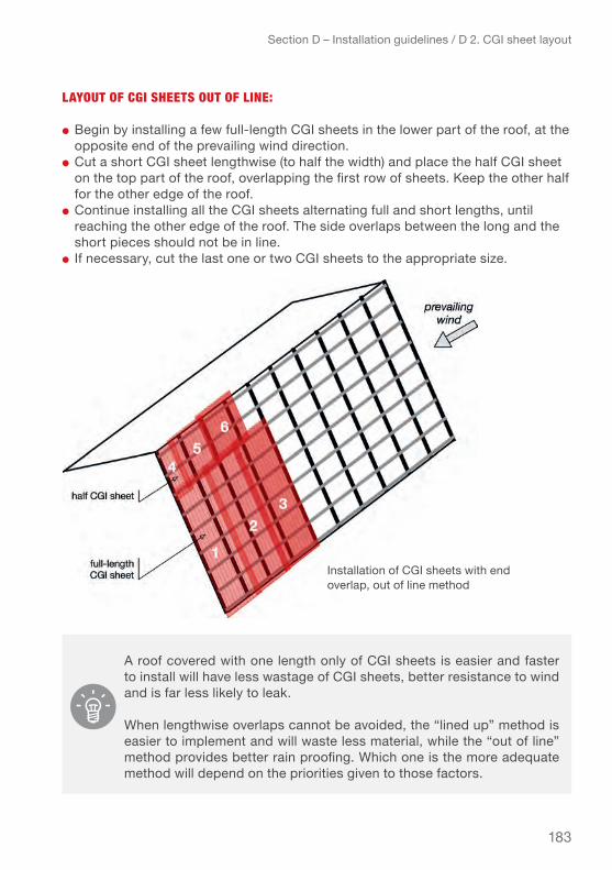
183
lAyout of cgi sheets out of line:
● Begin by installing a few full-length CGI sheets in the lower part of the roof, at the opposite end of the prevailing wind direction.
● Cut a short CGI sheet lengthwise (to half the width) and place the half CGI sheet on the top part of the roof, overlapping the first row of sheets. Keep the other half for the other edge of the roof.
● Continue installing all the CGI sheets alternating full and short lengths, until reaching the other edge of the roof. The side overlaps between the long and the short pieces should not be in line.
● If necessary, cut the last one or two CGI sheets to the appropriate size.
Section D – Installation guidelines / D 2. CGI sheet layout
A roof covered with one length only of CGI sheets is easier and faster to install will have less wastage of CGI sheets, better resistance to wind and is far less likely to leak.
When lengthwise overlaps cannot be avoided, the “lined up” method is easier to implement and will waste less material, while the “out of line” method provides better rain proofing. Which one is the more adequate method will depend on the priorities given to those factors.
installation of Cgi sheets with end overlap, out of line method
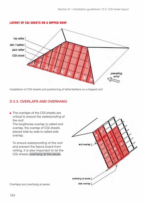
184
lAyout of cgi sheets on A hiPPeD Roof
d 2.3. overlApS And overhAng
● the overlaps of the Cgi sheets are critical to ensure the waterproofing of the roof.
The lengthwise overlap is called end overlap, the overlap of CGI sheets placed side by side is called side overlap.
To ensure waterproofing of the roof and prevent the fascia board from rotting, it is also important to let the Cgi sheets overhang at the eaves.
Section D – Installation guidelines / D 2. CGI sheet layout
Installation of CGI sheets and positioning of laths/battens on a hipped roof
Overlaps and overhang at eaves

185
siDe oveRlAPs
When placing the CGI sheets, ensure a side overlap of 1 or 2 corrugations, depend-ing on the pitch of the roof and the wind force:
In areas where wind-speeds are not expected to exceed 100 km /h and the pitch is higher than 15°, 1 corrugation / crest (approx. 5 cm) overlap can be enough but two is always recommended.
CGI sheet layout left to right (prevailing wind coming from the right):In fact, a 2-corrugation overlap corresponds to overlapping 1.5 corrugation pitches as shown in drawing page 187. A 1-corrugation overlap corresponds to overlapping only half a corrugation pitch.
enD oveRlAP
when more than one sheet is needed to cover the full slope of the roof, ensure sufficient end overlap depending on the pitch of the roof and the wind force.
Section D – Installation guidelines / D 2. CGI sheet layout
In all areas subject to winds-speeds over 100 km / h, the side overlap should be 2 corrugations / crest (approx. 12 cm)
Length of end overlap
Side overlap
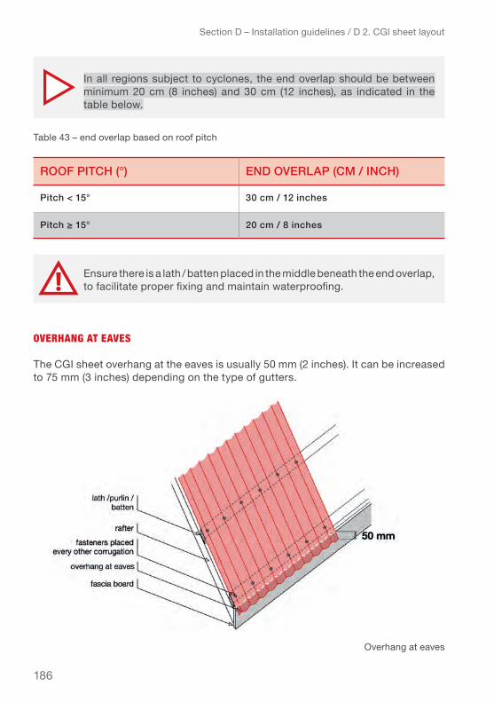
186
oveRhAng At eAves
The CGI sheet overhang at the eaves is usually 50 mm (2 inches). It can be increased to 75 mm (3 inches) depending on the type of gutters.
Section D – Installation guidelines / D 2. CGI sheet layout
In all regions subject to cyclones, the end overlap should be between minimum 20 cm (8 inches) and 30 cm (12 inches), as indicated in the table below.
Ensure there is a lath / batten placed in the middle beneath the end overlap, to facilitate proper fixing and maintain waterproofing.
roof pitch (°) end overlAp (cm / inch)
pitch < 15° 30 cm / 12 inches
Pitch ≥ 15° 20 cm / 8 inches
Table 43 – end overlap based on roof pitch
Overhang at eaves

187
Section D – Installation guidelines / D 2. CGI sheet layout
tiP: Don’t forget to consider the (5 cm) overhang at eaves when looking to cover the full roof slope with one sheet.
St Vincent & Grenadines, Hurricane Tomas, 2010: Installation of CGI sheets, cord at eaves overhang to line up the CGI sheets, marking of the location of
the laths in order to better place the roofing nails. (© French Red Cross)

188
d 3. fiXingS / fAStenerS
There are several types of fixings/fasteners for roofing, as mentioned in Chapter A – Materials. This chapter focuses on the correct installation of the most common and most effective types of fixings/fasteners for CGI sheets on timber and coconut wood supports:
● Roofing nails with twisted shank and rubber washer● Roofing screws with sealing washer
Roofing nails with smooth-shank should only be used in areas where wind speed are expected to be less than 100 km/h
BAsic Rules to ensuRe PRoPeR fiXing of the cgi sheeting:
● To ensure water-tightness of the fixing the rubber washer should be sufficiently compressed (as shown in the graphics below). If it is not compressed properly, there is higher possibility of leakage. If it is compressed too much, its durability may be reduced.
Roofing nAils:
Section D – Installation guidelines / D 3. Fixings / fasteners
Compression of rubber washer

189
Roofing scRews:
Section D – Installation guidelines / D 3. Fixings / fasteners
Fasteners must always be placed at the top of the corrugation (crest), in order to ensure the water-tightness. Placing the fasteners at the bot-tom of the corrugation can lead to leakage. Note that this does not apply when using ribbed roofing sheets.
Compression of sealing washer
Correct and incorrect position of the fastener on the Cgi sheet
roofing nails
roofing screws

190
● To improve the puncture resistance of the CGI sheet, large round or square seal-ing washers should be added between the head of the nail / screw and the CGI sheet. This is particularly important for thin CGI sheets.
Section D – Installation guidelines / D 3. Fixings / fasteners
Some builders with very limited budgets, often recycle pieces of tires or other rubber materials and use them as sealing washers for their roof fixings. There is not sufficient evidence to prove the water tightness and durability of such solutions, but when well implemented these solutions can probably come close to the effectiveness of commercially sold rubber washers.
PRActicAl tiPs:▹ When installing the CGI sheets, to span a string across the lath /
batten/purlin line or marking the lath/batten/purlin centre-line on the sheets will help to ensure the fastener will be well placed in the support below.
▹ To make hammering roofing nails into dense woods such as high-density coconut wood easier, lubricate the nail shanks with soap. This also helps for roofing screws. The effect on withdrawal resistance is negligible.
Sealing washer placed underneath the fastener head to improve the puncture resistance of the Cgi sheet

191
d 4. inStAllAtion detAilSThis chapter presents practical guidance on the correct implementation of important roof details as the eaves, verges and ridges. As these are the areas of a roof that are subjected to the strongest forces, proper implementation is particularly important to avoid weak points and ensure the resistance of the roof.
The drawings presented in this chapter are generic and can be used as reference for all kinds of roof shapes except for the few details that are particular to only one roof shape (e.g. hip caps for hipped roofs).
d.4.1. lAthS / bAttenS / purlinS
To ensure that the CGI sheets can be properly fixed to the supporting structure it is important to place the laths correctly, especially if there is an end overlap of the sheets. The necessary spacing of the laths needs to be calculated to resist the basic wind speed of the given context. A basic rule of thumb distance is around 60 cm.
The following steps provide guidance on how to install the laths correctly:
● The first lath/batten is positioned at the end of the eaves (lower end of the roof).
● The next lath/batten is positioned directly above the outside wall. This is impor-tant to take up the wind loads applied to the eaves.
To reinforce the eaves an additional lath/batten can be placed between these two first laths/battens. This is recommended if the eaves overhang is larger than the calculated distance between the laths/battens (see detailed explanation under D 4.2. eaves overhang).
● The upper lath/batten is placed between 10 and 15 cm from the centre of the ridge beam.
For single-pitch roof, the upper lath/batten can be placed either directly at the end of the roof (upper edge) if there is no ridge cap or 10-15 cm from the edge if there is a ridge cap / flashing. (See 4.6. end roof for more details).
● Hipped roofs also have an additional lath/batten along the hip angles. (For more details, see 4.5. Hip detail).
Section D – Installation guidelines / D 4. Installation details

192
Section D – Installation guidelines / D 4. Installation details
For the further laths/battens, continue as follows:
foR cgi sheets which coveR the full length of the sloPe (no enD oveRlAP):
Place the laths/battens at the calculated distance (usually 60 cm) from the lath located directly above the outside wall, until reaching the upper lath/batten. The last spacing is often less than the others, which helps to reinforce the particularly exposed ridge area.
foR cgi sheets shoRteR thAn the Roof sloPe (with one enD oveRlAP):
1. Determine the position of the lath/batten to which the upper edge of the CGI sheet placed in the lower part of the roof will be fixed. This lath must be placed at a distance from the eaves overhang that is equal to the length of the sheet less the length of the overhang at eaves (5 cm) less half the length of the recommend-ed end overlap.
eXAmPle: If the CGI sheet measures 2 m, the overhang at eaves is 5 cm, and the end overlap is 30 cm, then the lath / batten is positioned at 2.00 m-0.05m-0.30 m / 2 = 1.80 m from the edge of the eaves of the roof.
2. Evenly distribute the laths at maximum the calculated spacing (usually 60 cm centre-to-centre), between the lath right above the outside wall, the lath/batten where the sheets will overlap, and the lath at the ridge.
Positioning of laths / battens when using full-length CGI sheet

193
d.4.2. eAveS’ overhAng
There always has to be one lath at the end of the eaves and one above the outside wall, regardless of the spacing calculated for the laths, which will not necessarily be equal to the length of the eaves overhang. As the eaves overhang has to resist higher wind forces than the main surface of the roof, in many cases it is recommended to insert an additional lath at the eaves overhang.
eXAmPles:If the eaves overhang is 45 cm and the calculated maximum spacing between the laths/battens is 60 cm, the first lath/batten is placed at the edge of the eaves, the second is placed right above the outside wall so at only 45 cm from the one at the end of the eave. The rest of the laths are spaced at 60 cm (centre-to-centre) as calculated.
Section D – Installation guidelines / D 4. Installation details
Positioning of laths/battens when CGI sheets overlap

194
● If the eaves overhang is 60 cm and the maximum spacing between the laths / battens should be 45 cm, the first lath / batten is placed at the eaves, the second is placed right above the outside wall (approx. 60 cm from the eave edge) and a further lath is placed at mid- distance between the one at the eave and the one above the outside wall (approx. 30 cm on centre). The further laths / battens are placed at 45 cm centre-to-centre as calculated.
Section D – Installation guidelines / D 4. Installation details
Location of laths / battens at eaves overhang (case of short eaves)
Location of laths / battens at eaves overhang (long eaves)

195
Section D – Installation guidelines / D 4. Installation details
If the number of fasteners calculated for the eaves overhang is higher than half the number of corrugations / crest of a CGI sheet, insert an additional lath in order to allow a second row of nails, rather than nailing each corrugation / crest, as this could split the timber or coconut wood and thus reduce the withdrawal resistance of the fasteners and overall stability.
In areas prone to major cyclones (category 3–5), it is strongly recommended to keep the eaves overhang to 30 cm maximum. The r ecommended distance between the laths / battens is 30 cm at the eaves.
Double laths / battens at eaves overhang

196
d.4.3. edgeS / vergeS
There are several methods to realize the edges / verges detailing. The below are list-ed in order of the resistance to wind pressure (from weak to strong).
● Laths / battens / purlins left free
● installation of a fascia board
● Installation of a fascia board and the first CGI sheet folded over the fascia board
● installation of a fascia board and installation of fascia cap made of galvanized steel
Section D – Installation guidelines / D 4. Installation details
Jamaica: Installation of fascia cap over fascia board. (© French Red Cross)
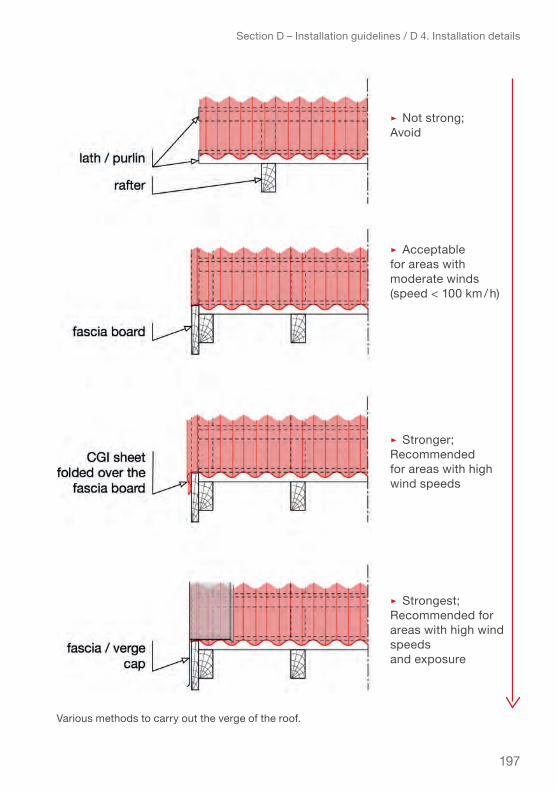
197
▹ Not strong;avoid
▹ acceptable for areas with moderate winds (speed < 100 km / h)
▹ Stronger;Recommended for areas with high wind speeds
▹ Strongest; Recommended for areas with high wind speeds and exposure
Section D – Installation guidelines / D 4. Installation details
Various methods to carry out the verge of the roof.

198
The fascia caps are installed before the ridge caps, starting at the bottom of the roof and going up to the ridge, or end roof for a single-pitch roof.
Section D – Installation guidelines / D 4. Installation details
installation of fascia caps
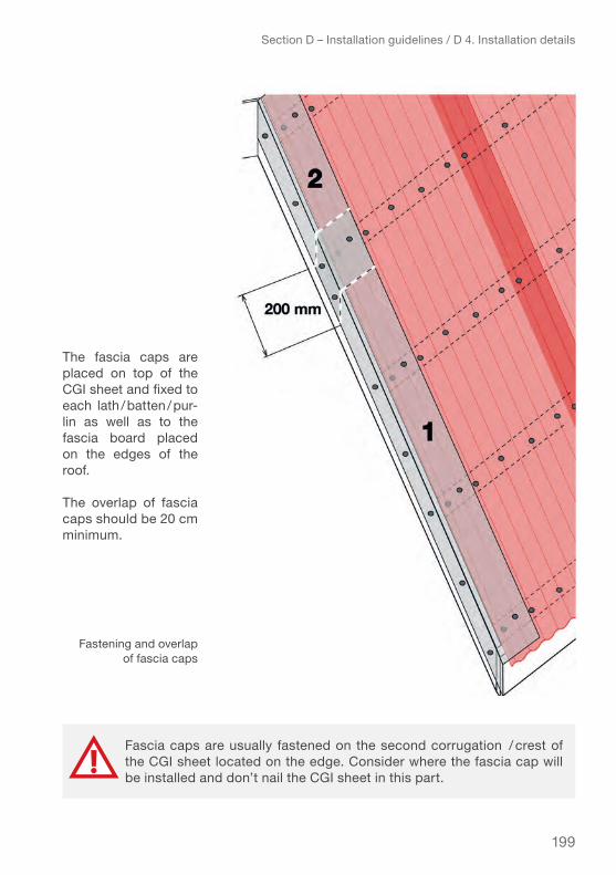
199
the fascia caps are placed on top of the CGI sheet and fixed to each lath / batten / pur-lin as well as to the fascia board placed on the edges of the roof.
the overlap of fascia caps should be 20 cm minimum.
Section D – Installation guidelines / D 4. Installation details
Fascia caps are usually fastened on the second corrugation / crest of the CGI sheet located on the edge. Consider where the fascia cap will be installed and don’t nail the CGI sheet in this part.
Fastening and overlap of fascia caps

200
d 4.4. ridge cApS
The ridge caps are placed last, starting on the side “away” from the prevailing wind, the same as for the CGI sheets.
Section D – Installation guidelines / D 4. Installation details
tiP: The CGI sheets are not fastened to the upper lath / batten until the ridge cap is in place. Fastening the ridge caps at the same time fastens the upper part of the CGI sheets.
Installation of ridge caps

201
Ridge caps are usually fastened at every other / crest. If fixing at every corruga-tion (depending on the type of fixings / fasteners and calculated wind pressure) consider using a wider lath (e.g., 2" x 4" instead of 2" x 3") to avoid splitting the wood by nailing every corrugation.
the overlap between the Cgi sheets and the ridge cap is at least 15 cm (6 inches).
The size of the ridge cap wings should be at least 20 cm to allow a 15 cm overlap between the CGI sheets and ridge cap.
The upper lath / batten should be placed between 10 to 15 cm (4-6 inches) on cen-tre from the ridge beam centre, depend-ing on the size of the ridge cap wings.
Section D – Installation guidelines / D 4. Installation details
Fastening of ridge caps
Overlap of CGI sheet and ridge cap
Location of the upper lath / batten
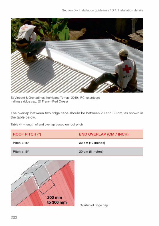
202
The overlap between two ridge caps should be between 20 and 30 cm, as shown in the table below.
Section D – Installation guidelines / D 4. Installation details
roof pitch (°) end overlAp (cm / inch)
pitch < 15° 30 cm (12 inches)
Pitch ≥ 15° 20 cm (8 inches)
Table 44 – length of end overlap based on roof pitch
Overlap of ridge cap
St Vincent & Grenadines, hurricane Tomas, 2010: RC volunteers nailing a ridge cap. (© French Red Cross)

203
d 4.5. hip detAilS (hipped roofS)
The hip capping is placed before the ridge capping. The hip cap overlap is 20 cm minimum.
The hip caps are usually nailed or screwed on top of every other corrugation / crest. For resistance to very strong winds in high exposure use a wider lath/batten/purlin (e.g., 2" x 4" instead of 2" x 3") so the hip caps can be nailed at every corrugation, but slightly offset in order to not split the laths.
The ridge cap is fixed last and covers CGI sheets and hip caps for a watertight and resistant roof.
Section D – Installation guidelines / D 4. Installation details
Installation of ridge cap on hipped roof and fastening of hip and ridge caps
installation of hip caps
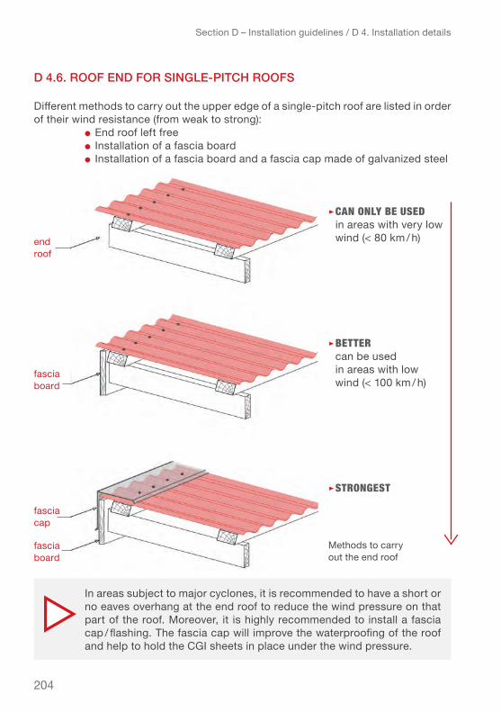
204
d 4.6. roof end for Single-pitch roofS
Different methods to carry out the upper edge of a single-pitch roof are listed in order of their wind resistance (from weak to strong):
● end roof left free● installation of a fascia board● Installation of a fascia board and a fascia cap made of galvanized steel
▹ cAn only Be useD in areas with very low wind (< 80 km / h)
▹ BetteR can be used in areas with low wind (< 100 km / h)
▹ stRongest
Section D – Installation guidelines / D 4. Installation details
In areas subject to major cyclones, it is recommended to have a short or no eaves overhang at the end roof to reduce the wind pressure on that part of the roof. Moreover, it is highly recommended to install a fascia cap / flashing. The fascia cap will improve the waterproofing of the roof and help to hold the CGI sheets in place under the wind pressure.
end roof
fascia board
fascia board
fascia cap
Methods to carry out the end roof

205
d 5. compAriSon of eXemplArY cASe StudY cAlculAtionS
this chapter presents a selection of the case studies that have been calculated (for this case that keeps the spacing of 60 cm centres for the laths) to show how the spacing between the rafters changes as well as the number of fixings as a function of the applied wind speeds and exposure situation.
Some roofs can resist extreme wind speed, while others are only suitable in areas with maximum category-1 cyclones.
The information provided is based on the case study and calculations of a “closed” shelter model with:
● Shelter dimensions 3 m x 6 m● Elevation from the ground of 75 cm, total height of the ridge: 4 m● Eaves and verge overhang of 45 cm● Rafters: 38 x 89 mm / 2”x 4”● Distance between the rafters vaires from 1.20 m to 0.30 m, adjusted as
necessary to resist the assumed loads● Laths: 38 x 64 mm / 2”x 3”● Distance between the laths in all examples 0.60 m in order to be able to compare
the number of fixings per lath● 26 gauge / 0.551 mm CGI sheet of 914 mm / 36 in (12 corrugations / crest)● Type of fixings/fasteners: roofing nails smooth-shank (diameter = 4.19 mm),
roofing nails twisted-shank (3.76 mm) and roofing screws (4.17 mm), length = 60 mm (2-½”), as required to resist the different wind speeds
● Penetration depth of the fixing / fastener: 38 mm
The drawings in this chapter show for each chosen example a way to position the fasteners on the CGI sheets depending on the type of fasteners. The number of fas-teners is higher all around the edges (eaves, verges, ridge and hip angles) than in the main part of the slope.
Section D – Installation guidelines / D 5. Comparison of exemplary case study calculations
The number of fasteners is given per width of the CGI per lath / batten (support). Example: if the number of fasteners for the edges is 6 then six fasteners should be placed across the width of the Cgi sheet on each lath / batten.

206
Section D – Installation guidelines / D 5. Comparison of exemplary case study calculations
You can calculate the quantity of fasteners that you will need to safely fasten the CGI sheets for your own shelter design by running the Roof estimate form (Excel spread-sheet, Annex 7). The Roof estimate form provides the number of fasteners needed for the edges of the roof and for the main part of the slope.
The distance between the roofing nails or screws should be at least the width of the lath, in order to avoid splitting and weakening the lath. This means, for timber laths of 38 x 64 mm / 2”x 3” the distance between the nails or screws should be at least 65 mm. Thus nailing CGI sheets with a corrugation pitch of 79 mm in every corrugation is possible. However this depends very much on the type of timber or wood used and can be different especially for harder woods. It is therefore recommended to undertake a nailing test on the timber used for the laths to check the splitting behaviour.
If the required number of fixings per sheet per lath is higher than half the corrugations of the sheet, it is recommended:● At the eaves overhang, to insert an additional lath● At the ridge and hip angles, to use a wider lath (e.g., 2" x 4" instead
of a 2" x 3") and slightly offset each nail
Jamaica, Hurricane Dean, 2007: Builders covering a roof with CGI sheets. (© French Red Cross)
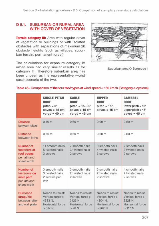
207
Section D – Installation guidelines / D 5. Comparison of exemplary case study calculations
d 5.1. SuburbAn or rurAl AreA with cover of vegetAtion
terrain category iii: Area with regular cover of vegetation or buildings or with isolated obstacles with separations of maximum 20 obstacle heights (such as villages, subur-ban terrain, permanent forest)
The calculations for exposure category IV urban area had very similar results as for category III. Therefore suburban area has been chosen as the representative (worst case) scenario of the two.
table 45– comparison of the four roof types at wind speed < 150 km / h (category-1 cyclone)
single-Pitch Roofpitch = 5°eaves = 45 cmverge = 40 cm
gABle Roofpitch = 15–30°eaves = 45 cmverge = 45 cm
hiPPeD Roofpitch = 15°eaves = 45 cm
gAmBRel Roof lower pitch = 15°upper pitch = 45°eaves = 45 cm
distance between rafters
0.40 m 0.60 m 0.90 m 0.60 m
distance between laths
0.60 m 0.60 m 0.60 m 0.60 m
number of fasteners at roof edges per lath and sheet width
11 smooth nails 5 twisted nails 3 screws
7 smooth nails 3 twisted nails 2 screws
9 smooth nails 4 twisted nails3 screws
7 smooth nails 3 twisted nails2 screws
number of fasteners on main part per lath and sheet width
3 smooth nails 3 twisted nails2 screws per lath
3 smooth nails2 twisted nails2 screws
3 smooth nails2 twisted nails2 screws
4 smooth nails2 twisted nails2 screws
hurricane strap / tie between rafter and wall plate
Needs to resist:Vertical force > 4383 N,Horizontal force > 617 N
Needs to resist:Vertical force > 3123 N,Horizontal force > 76 N
Needs to resist:Vertical force > 4304 N,Horizontal force > 262 N
Needs to resist:Vertical force > 5228 N,Horizontal force > 117 N
Suburban area © Eurocode 1
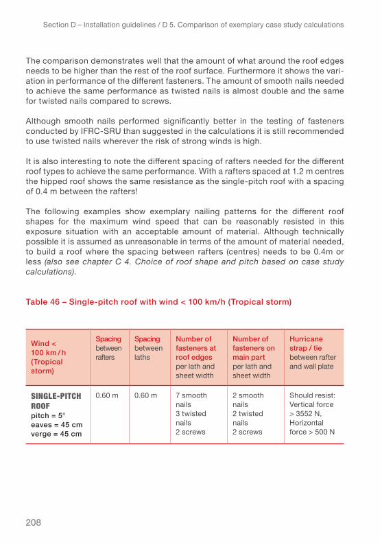
208
The comparison demonstrates well that the amount of what around the roof edges needs to be higher than the rest of the roof surface. Furthermore it shows the vari-ation in performance of the different fasteners. The amount of smooth nails needed to achieve the same performance as twisted nails is almost double and the same for twisted nails compared to screws.
Although smooth nails performed significantly better in the testing of fasteners conducted by IFRC-SRU than suggested in the calculations it is still recommended to use twisted nails wherever the risk of strong winds is high.
It is also interesting to note the different spacing of rafters needed for the different roof types to achieve the same performance. With a rafters spaced at 1.2 m centres the hipped roof shows the same resistance as the single-pitch roof with a spacing of 0.4 m between the rafters!
The following examples show exemplary nailing patterns for the different roof shapes for the maximum wind speed that can be reasonably resisted in this exposure situation with an acceptable amount of material. Although technically possible it is assumed as unreasonable in terms of the amount of material needed, to build a roof where the spacing between rafters (centres) needs to be 0.4m or less (also see chapter C 4. Choice of roof shape and pitch based on case study calculations).
table 46 – Single-pitch roof with wind < 100 km/h (tropical storm)
Section D – Installation guidelines / D 5. Comparison of exemplary case study calculations
wind < 100 km / h (tropical storm)
Spacing between rafters
Spacing between laths
number of fasteners at roof edges per lath and sheet width
number of fasteners on main part per lath and sheet width
hurricane strap / tie between rafter and wall plate
single-Pitch Roofpitch = 5°eaves = 45 cmverge = 45 cm
0.60 m 0.60 m 7 smooth nails 3 twisted nails 2 screws
2 smooth nails2 twisted nails2 screws
Should resist:vertical force > 3552 N,Horizontal force > 500 N

209
Section D – Installation guidelines / D 5. Comparison of exemplary case study calculations
Position of fasteners on a 5° single-pitch roof with low
wind speed (< 100 km / h)
smooth-shank roofing nail
roofing srcew with wide
sealing washer
twisted-shank roofing nail

210
table 47 – gable roof with wind < 175 km / h (category-2)
Section D – Installation guidelines / D 5. Comparison of exemplary case study calculations
wind 175 km / h (cat-egory-2)
Spacing between rafters
Spacing between laths
number of fasteners at roof edges per lath and sheet width
number of fasteners on main part per lath and sheet width
hurricane strap / tie between rafter and wall plate
gABle Roofpitch = 15°eaves = 45 cmverge = 45 cm
0.60 m 0.60 m 9 smooth nails 4 twisted nails3 screws
4 smooth nails 2 twisted nails2 screws
Should resist:vertical force > 4251 N,Horizontal force > 76 N
Position of fasteners on a 15° gable roof with wind speed < 175 km / h
smooth-shank
roofing nail
roofing screw with
wide sealing washer
twisted-shank roofing nail
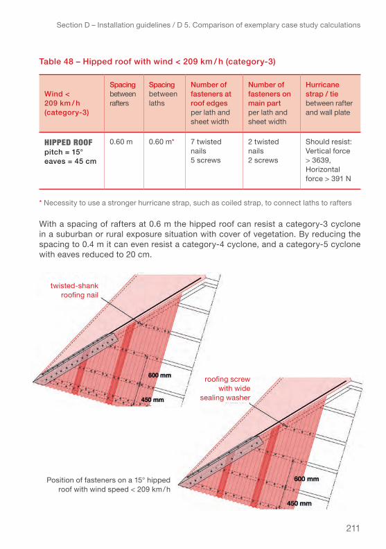
211
table 48 – hipped roof with wind < 209 km / h (category-3)
With a spacing of rafters at 0.6 m the hipped roof can resist a category-3 cyclone in a suburban or rural exposure situation with cover of vegetation. By reducing the spacing to 0.4 m it can even resist a category-4 cyclone, and a category-5 cyclone with eaves reduced to 20 cm.
Section D – Installation guidelines / D 5. Comparison of exemplary case study calculations
wind < 209 km / h (category-3)
Spacing between rafters
Spacing between laths
number of fasteners at roof edges per lath and sheet width
number of fasteners on main part per lath and sheet width
hurricane strap / tie between rafter and wall plate
hiPPeD Roofpitch = 15°eaves = 45 cm
0.60 m 0.60 m* 7 twisted nails 5 screws
2 twisted nails 2 screws
Should resist:vertical force > 3639,Horizontal force > 391 N
* Necessity to use a stronger hurricane strap, such as coiled strap, to connect laths to rafters
Position of fasteners on a 15° hipped roof with wind speed < 209 km / h
twisted-shank roofing nail
roofing screw with wide
sealing washer

212
d 5.2. rurAl AreA with low vegetAtion
teRRAin cAtegoRy ii: Area with low veg-etation such as grass and isolated obsta-cles (trees, buildings) with separations of at least 20 obstacle heights.
table 49 – comparison of the four roof types at wind speed < 150 km/h (category-1 cyclone)
Section D – Installation guidelines / D 5. Comparison of exemplary case study calculations
single-Pitch Roofpitch = 5°eaves = 45 cmverge = 30 cm
gABle Roofpitch = 15–30°eaves = 45 cmverge = 45 cm
hiPPeD Roofpitch = 15–30°eaves = 45 cm
gAmBRel Roof lower pitch = 15°upper pitch = 45°eaves = 45 cm
distance between rafters
0.30 m 0.60 m 0.60 m 0.45 m
distance between laths
0.60 m 0.60 m 0.60 m 0.60 m
number of fasteners at edges per lath and sheet width
6 twisted nails4 screws
5 twisted nails 3 screws
5 twisted nails 4 screws
4 twisted nails 3 screws
number of fasteners on main part per lath and sheet width
2 twisted nails 2 screws
2 twisted nails2 screws
2 twisted nails 2 screws
3 twisted nails 2 screws
hurricane strap / tie between rafter and wall plate
Should resist:Vertical force > 4109 N,Horizontal force > 668 N
Should resist:Vertical force > 4343 N,Horizontal force > 105 N
Should resist:Vertical force > 3991 N,Horizontal force > 246 N
Should resist:Vertical force > 5514 N,Horizontal force > 123 N
Rural area with low vegetation © Eurocode

213
In this exposure situation the single-pitch roof is already over the limit of reason-able material consumption, with a spacing of rafters at 0.3 m centre-to-centre. Also Gambrel roofs are close to the assumed limit of 0.4 m rafter spacing centre-to-centre already.
table 50 – gable roof with wind < 150 km / h (category-1)
Section D – Installation guidelines / D 5. Comparison of exemplary case study calculations
wind 150 km / h (cat-egory-1)
Spacing between rafters
Spacing between laths
number of fasteners at roof edges per lath and sheet width
number of fasteners on main part per lath and sheet width
hurricane strap / tie between rafter and wall plate
gABle Roofpitch = 30°eaves = 45 cmverge = 45 cm
0.60 m 0.60 m 5 twisted nails 3 screws
2 twisted nails 2 screws
Should resist:vertical force > 4243 N,Horizontal force > 105 N
Position of fasteners on a 30° gable roof with wind speed < 150 km / h
roofing screw with
wide sealing washer
twisted-shank roofing nail
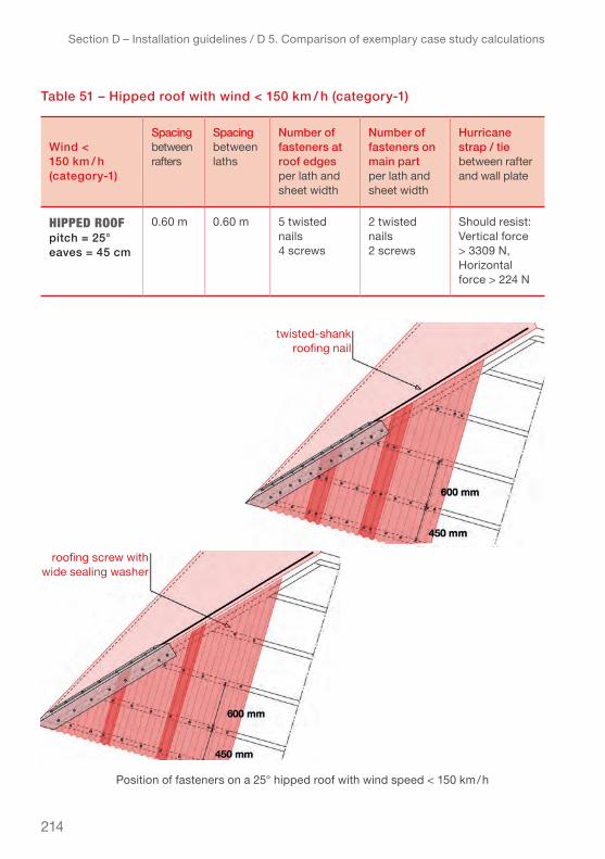
214
table 51 – hipped roof with wind < 150 km / h (category-1)
Section D – Installation guidelines / D 5. Comparison of exemplary case study calculations
wind < 150 km / h (category-1)
Spacing between rafters
Spacing between laths
number of fasteners at roof edges per lath and sheet width
number of fasteners on main part per lath and sheet width
hurricane strap / tie between rafter and wall plate
hiPPeD Roofpitch = 25°eaves = 45 cm
0.60 m 0.60 m 5 twisted nails 4 screws
2 twisted nails 2 screws
Should resist:vertical force > 3309 N,Horizontal force > 224 N
Position of fasteners on a 25° hipped roof with wind speed < 150 km / h
roofing screw with wide sealing washer
twisted-shank roofing nail

215
d 5.3. coAStAl AreA
teRRAin cAtegoRy 0: Sea, coastal area exposed to the open sea.
table 52 – comparison of the four roof types at wind speed < 150 km/h (category-1 cyclone)
Section D – Installation guidelines / D 5. Comparison of exemplary case study calculations
single-Pitch Roofpitch = 5°eaves = 20 cmverge = 0 cm
gABle Roofpitch = 15–30°eaves = 30 cm
hiPPeD Roofpitch = 15–30°eaves = 45 cm
gAmBRel Roof lower pitch = 15°upper pitch = 45°eaves = 45 cm
distance between rafters
0.30 m 0.45 0.60 m 0.30 m
distance between laths
0.60 m 0.60 m 0.60 m* 0.60 m
number of fasteners at roof edges per lath and sheet width
9 twisted nails 6 screws
6 twisted nails 4 screws
8 twisted nails5 screws
6 twisted nails4 screws
number of fasteners on main part per lath and sheet width
2 twisted nails2 screws
3 twisted nails2 screws
2 twisted nails2 screws
3 twisted nails2 screws
hurricane strap / tie between rafter and wall plate
Should resist:Vertical force > 4456 N,Horizontal force > 735 N
Should resist:Vertical force > 5290 N,Horizontal force > 127 N
Should resist:Vertical force > 5605 N,Horizontal force > 345 N
Should resist:Vertical force > 5105 N,Horizontal force > 114 N
* Necessity to use a stronger hurricane strap, such as coiled strap, to connect laths to rafters
Coastal area © eurocode

216
The comparison illustrates that in a coastal exposure situation the material required to build the supporting roof structure becomes very large. The model shelter with gable roof used for the calculations could still resist a category-3 cyclone when the pitch is kept at 15°, the verge reduced to 20 cm and the spacing of the rafters at 0.45 m.
Only the hipped roof can still resist the category-2 and 3 cyclones with an accept-able material effort (spacing of 0.60 m spacing of rafters). For category-4 cyclones the hipped roof requires spacing of 0.30 m for the rafters.
table 53 – gable roof with wind < 209 km / h (category-3):
Section D – Installation guidelines / D 5. Comparison of exemplary case study calculations
wind 209 km / h ( category-3)
Spacing between rafters
Spacing between laths
number of fasteners at roof edges per lath and sheet width
number of fasteners on main part per lath and sheet width
hurricane strap / tie between rafter and wall plate
gABle Roofpitch = 15°eaves = 20 cmverge = 0 cm
0.45 m 0.60 m* 8 twisted nails 5 screws
4 twisted nails 3 screws
Should resist:vertical force > 5732 N,Horizontal force > 473 N
Position of fasteners on a 15° gable roof with wind speed < 209 km / h
roofing screw with wide
sealing washer
twisted-shank roofing nail

217
table 54 – hipped roof with wind < 250 km / h (category-4):
As shown, the calculations suggest that the shelter model used for the case stud-ies is not suitable for such exposed conditions. If construction of shelters in highly exposed areas is necessary, the design should be adapted to be more resistant, including reducing the length of the eaves overhang and/or verge, as well as the spacing between rafters and laths.
in sites with such high exposure (and possibly with sandy soil) the entire structure becomes critical in order to avoid over-turning of the whole shelter. For example if lightweight construction is used, foundations need to be deeper and wider than for the same shelters in a less exposed situation.
Section D – Installation guidelines / D 5. Comparison of exemplary case study calculations
wind < 250 km / h (category-4)
Spacing between rafters
Spacing between laths
number of fasteners at roof edges per lath and sheet width
number of fasteners on main part per lath and sheet width
hurricane strap / tie between rafter and wall plate
hiPPeD Roofpitch = 15°eaves = 25 cm
0.30 m 0.45 m* 9 screws 3 screws Should resist:vertical force > 5991 N,Horizontal force > 691 N
Position of fasteners on a 15° hipped roof with wind speed < 250 km / h
* Necessity to use a stronger hurricane strap, such as coiled strap, to connect laths to rafters.The spacing between rafters can be kept at 0.60 m centre-to-centre, if the hurricane straps joining the rafters to the wall plates can withstand higher loads (vertical and horizontal forces). The spacing between the laths can be kept at 0.60 m centre-to-centre by using coiled straps instead of regular hurricane straps.
218
Section D – Installation guidelines / Practical Summary
prActicAl SummArY – Section d
To make the roof more wind resistant and especially strengthen the most exposed parts of the roof covering:
● Minimize verges and eave overhangs.● Place fascia boards all around the roof and cover with fascia caps● Use hip and ridge caps ● Try to design the shelter with dimensions that allow one length of CGI sheets to
cover the full length of the roof slope ▹ check available lengths of CGI sheets when designing the shelter.
● Use twisted-shank roofing nails or roofing screws with wide sealing washers (diam-eter > 25-30 mm) when planning for resistance to cyclones category-2 or higher.
cgi sheet lAyout:
● Start laying out the CGI sheets for the roof covering starting from the side away from the prevailing wind direction (i.e. if the prevailing wind is blowing from right to left, then start installing the CGI sheets on the left side of the roof): The second CGI sheet will overlap over the first one.
● Position the CGI sheets with the “shiny” side facing the sky. The “shiny” side often has a weather treatment that the other side does not.
● Use a cord placed at the eaves overhang to properly line up the CGI sheets when installing.
oveRlAPs:
● Overhang of the CGI sheet at eaves should be 5 cm–8 cm / 2”–3” over the fascia board (or end lath); make sure to consider this when calculating the length of the CGI sheet.
● If more than one length of CGI sheet is needed to cover the length of the roof slope, the overlap of the CGI sheets lengthwise, called end overlap, should be min. 20 cm / 8” for roof pitch ≥ 15°, and 30 cm / 12” for pitches under 15°.
● Make sure to place a lath/batten under end overlaps of two sheets to fasten them properly.
● Side overlap can be 1 corrugation / crest, if roof pitch > 15° and wind speed < 100 km / h. Where wind speeds over 100 km / h are expected always overlap 2 corrugations/crest!
● For CGI sheets, fasteners are always placed on top of the corrugations / crest. Avoid placing the fasteners in the water channel (bottom of the corrugation) as it increases the risk of leakage.
● The quantity of fasteners around the edges of the roof (eaves, verges, hips and ridge) has to be higher (up to double than for the rest of the roof) because wind pressure there is the highest.

219
Section D – Installation guidelines / Practical Summary
instAllAtion DetAils:
● One lath/batten should always be placed right above the outside wall.● The lath/batten at the end of the roof (the one at the eaves) can be doubled if the
number of fasteners to be installed is greater than half the number of corrugations (e.g., if 8 roofing nails should be placed on 12 corrugations, you should double the laths/battens and distribute the quantity of nails accordingly over the two laths).
● If nailing each corrugation is required, test nailing at the distance of every cor-rugation (every 79 mm) to see if the laths split. Otherwise insert a second lath and distribute the necessary amount of nails over two laths.
● The upper lath/batten (the one close to the ridge) should be placed around 12 cm from the centre of the ridge or end roof (for single-pitch roof).
● Fascia caps (for gable, gambrel or single-pitch roofs) or hip caps (for hipped roofs) are always installed over the CGI sheets; ridge caps are installed last.
● Ridge caps should overlap at least 20 cm / 8” for roof pitches ≥ 15° and 30 cm / 12” for lower pitches.
● Fascia caps and hip caps should overlap at least 20 cm / 8” to ensure water tightness.
● Ridge caps should overlap at least 15 cm / 6” over the CGI sheets.
Roof shAPes:The single pitch roof can be a good choice in areas with wind speeds up to 100 km / h, in not very exposed areas such as urban areas or rural areas with cover of vegetation the single pitch roof can resist up to 150 km / h (category-1 cyclones).
For high exposure situations like coastal areas or rural areas without covering veg-etation the gable and gambrel roofs can resist up to category-1 cyclones.
The gable roof and the hipped roof can resist up to category-3 before the materials needed to make the roof resistant becomes quite excessive (spacing of rafters at 30 cm) for the type of shelter used in the calculations.
If no sites in less exposed locations are available the shelter design needs to be adapted to better resist the high wind forces.
If feasible in terms of budget, a roof decking below the rafters will provide a good bracing to the roof frame as well as improve the thermal and acoustical performance of the CGI sheet roof.
use the Roof estimate form (Excel spreadsheet, Annex 7) for more accurate information about the number of fasteners per lath/batten and per CGI sheet for your own shelter.
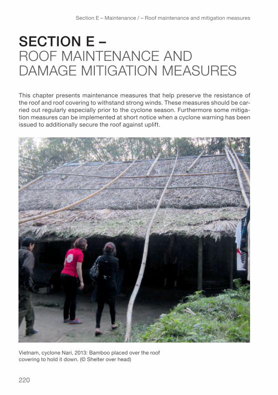
220
Section E – Maintenance / – Roof maintenance and mitigation measures
this chapter presents maintenance measures that help preserve the resistance of the roof and roof covering to withstand strong winds. These measures should be car-ried out regularly especially prior to the cyclone season. Furthermore some mitiga-tion measures can be implemented at short notice when a cyclone warning has been issued to additionally secure the roof against uplift.
Vietnam, cyclone Nari, 2013: Bamboo placed over the roof covering to hold it down. (© Shelter over head)
Section e – roof maIntenance and damage mItIgatIon measures

221
Section E – Maintenance / E 1. Roof maintenance
e 1. roof mAintenAnceA shelter/house needs regular maintenance to avoid deterioration of the structure and keep the weather proofing intact. Checking the condition of the roof structure (such as rafters, laths/battens, purlins, ridge beam, etc.) and all the other structural elements of the shelter, whether made of timber, coconut wood, bamboo or metal, each year before the cyclone season, can greatly reduce the risk of damage to the roof and roof covering. Also regularly check the window shutters and doors.
The following chapter describes in detail how to check the critical elements of the roof:
● Check the laths / battens (timber / coconut wood / bamboo) and other structural elements of the roof for cracks, rotting or insect/rodent infestation.
● Check the CGI sheets for corrosion or other damages. ● Check the fixings of the CGI sheets and tighten where necessary. ● Check the hurricane straps / ties for corrosion and their fixings for tightness.● Check the gutters if they are clean and well fastened.
e 1.1. lAthS / bAttenS And other StructurAl elementS
The CGI sheets cannot be securely fastened if the laths/battens are not in good con-dition, just as the roof cannot be securely anchored to the structure if elements of the structure are not in good condition. Before checking the condition of the CGI sheets, make sure that the entire shelter structure is healthy.
● Verify that the parts of the roof frame and structural elements are not rotten or attacked by termites or other wood borers. Replace rotten or infested elements, and in the case of an attack by wood borers, treat the framework as a whole to prevent the spread.
● Verify that the parts of the roof frame and structural elements are free from rust. Light corrosions can be removed (with metal brush or sand paper) and the affect-ed elements protected with a specific paint, such as zinc-rich paint for parts made of galvanized steel and anti-corrosion paint for parts made of raw steel.
e 1.2. cgi SheetS
Inspecting the CGI sheets each year before the cyclone season will help to identify any weak points that increase the risk of leakage or uplift of the CGI sheets, so that these can be mitigated:
● If the CGI sheets (hot-dip galvanized) have less than 5 % rust (depending on the sheet size around 5-10 cm2 of rust on the sheet) on their total galvanized surface, the steel base is not compromised and retains its original strength.
222
Section E – Maintenance / E 1. Roof maintenance
● If The CGI sheets are very corroded, already with small holes, the steel base is compromised.
▹ Seal the holes with a waterproof product (bitumen flashing tape, sealant) to at least prevent leakage. ▹ Look to replace the corroded CGI sheets as soon as possible.
● Particularly check for rust around the fixings / fasteners:▹ If the area around the fixings / fasteners is only slightly corrod-ed you can apply some zinc paint and replace the rubber / seal-ing washer by a wider sealing washer large enough to cover the corroded part as to grip on the no-corroded surface of the CGI sheet. ▹ If the area around the fixings / fasteners is very corroded remove the fixing/fastener, place it on the next corrugation and seal the hole with a waterproofing product.
PAinting the cgi sheets to eXtenD theiR seRvice life1 :
Painting the CGI sheets can extend their service life, as mentioned in chapter A 2.3 Coating thickness and service life for CGI sheets. However since the zinc coating of CGI sheets offers very low adherence to paint the surface has to be well prepared:
● Choose the right kind of paint, such as acrylic, vinyl or epoxy paints for galva-nized steel. Availability of paints varies greatly in different regions of the world. Contact a leading supplier locally present on the market. In particular, marine paint suppliers should be knowledgeable on this topic.
● Prepare the surface well to increase the adhesion of the paint by either:▹ Chemical removal of the oxidation: Clean the surface to be painted with the product recommended for the chosen paint, rinse and dry. ▹ Mechanical removal of the oxidation: Lightly sand the surface and remove dust before painting.
Instructions on which preparation is most suitable should be provided by the paint manufacturer.
1 Source: Zink Info Benelux
Remove corrosion superficially with sandpaper and apply zinc paint on the corroded parts of the CGI sheets to extend their service life.
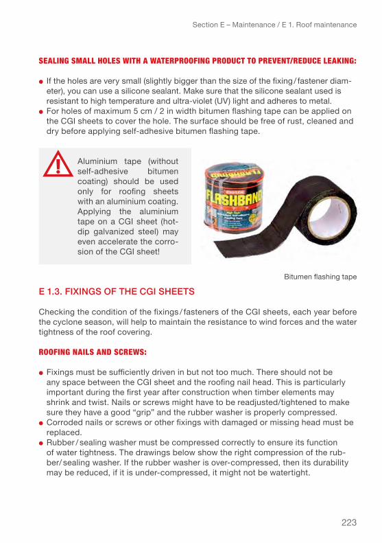
223
Section E – Maintenance / E 1. Roof maintenance
seAling smAll holes with A wAteRPRoofing PRoDuct to PRevent/ReDuce leAking:
● If the holes are very small (slightly bigger than the size of the fixing / fastener diam-eter), you can use a silicone sealant. Make sure that the silicone sealant used is resistant to high temperature and ultra-violet (UV) light and adheres to metal.
● For holes of maximum 5 cm / 2 in width bitumen flashing tape can be applied on the CGI sheets to cover the hole. The surface should be free of rust, cleaned and dry before applying self-adhesive bitumen flashing tape.
e 1.3. fiXingS of the cgi SheetS
Checking the condition of the fixings / fasteners of the CGI sheets, each year before the cyclone season, will help to maintain the resistance to wind forces and the water tightness of the roof covering.
Roofing nAils AnD scRews:
● Fixings must be sufficiently driven in but not too much. There should not be any space between the CGI sheet and the roofing nail head. This is particularly important during the first year after construction when timber elements may shrink and twist. Nails or screws might have to be readjusted/tightened to make sure they have a good “grip” and the rubber washer is properly compressed.
● Corroded nails or screws or other fixings with damaged or missing head must be replaced.
● Rubber / sealing washer must be compressed correctly to ensure its function of water tightness. The drawings below show the right compression of the rub-ber / sealing washer. If the rubber washer is over-compressed, then its durability may be reduced, if it is under-compressed, it might not be watertight.
aluminium tape (without self-adhesive bitumen coating) should be used only for roofing sheets with an aluminium coating. Applying the aluminium tape on a Cgi sheet (hot-dip galvanized steel) may even accelerate the corro-sion of the CGI sheet!
Bitumen flashing tape

224
● The fixing / fastener must have a waterproof rubber washer. If the rubber is worn (brittle or cracked), it should be replaced in order to ensure the waterproofing.
Section E – Maintenance / E 1. Roof maintenance
tiP: after installation, the rubber/sealing washer should not be able to move or turn. The CGI sheet under the fixing/fastener should not be deformed (dented).
Picture above: Rubber washer compression for roofing nail. Picture below: Sealing washer compression for roofing screw.

225
e 1.4. hurricAne StrApS / tieS And their fiXingS
Ensuring good condition of the hurricane straps / ties and their fixings / fasteners, each year before the cyclone season can greatly reduce the risk of the roof uplifting during a storm.
● Neither hurricane straps nor fixings should be rusty. In case they are, it is recom-mended to:
▹ If only slightly rusty, remove the rust, clean the surface and paint it with a protective paint (zinc-rich paint for hurricane straps made of galvanized steel, and anti-corrosion for the ones made of raw steel).▹ Replace the ones that are very rusty (more than 5 % corrosion of their surface).▹ Ensure that hurricane straps are fastened tightly to the sup-port structure without space between the hurricane straps and support. This is particularly important during the first year after construction when timber members may shrink and twist. Nails or screws might have to be readjusted / tightened a bit to make sure the straps are securely fastened.
For more information on hurricane straps / ties, refer to Chapter A 6. Hurricane straps / ties.
e 1.5. check the gutterS
The gutters are important to collect the rainwater runoff from the roof so it will not affect the walls and foundations. Check the condition of the gutters, especially before the rainy season or a storm
● Ensure that the gutters are securely fastened. It is recommended to fix the gutters to the fascia board every 50 cm.
● Ensure that there are no leaves and other obstacles to the discharge of rainwater and where necessary clean the gutter to allow proper discharge of the rainwater.
Section E – Maintenance / E 1. Roof maintenance
tiPs: If rubber washers are not available: ▹ Use a waterproof product, such as silicone sealant or bitumen flashing tape (see chapter E 1.2. CGI sheets) to bond or cover the fixing / fastener when the rubber washers have lost their effectiveness and cannot be replaced.▹ It is also possible to use items made of rubber, such as flip-flops or old tires for temporary repairs. But be aware that these materials are less effective and resistant than original rubber washers.

226
e 2. mitigAtion meASureS
The air tightness of the shelter is an important factor for its wind resistance. If the shelter / house has airtight walls and all the doors and windows are properly closed, it is more resistant to wind pressure. However, if a door or window is open or opens during the storm, the pressure increases inside the shelter and the roof is more likely to be uplifted and the shelter to be damaged.
If the walls are not airtight, as for example bamboo or palm leaf screens, it can be better to remove the exterior wall screens to prevent them from being damaged.
Depending on the air tightness of the walls different measures can be implemented to reduce the effects of wind on the roof and help reinforce the roof against uplift.
e 2.1. Shelter with outSide wAllS thAt Are not Airtight
If the outside walls of the shelter are not airtight, such as walls made of bamboo screens or palm leave mats, it can be safer to remove these wall screens, the inside partitions and all the furniture and store them in a safer location (e.g. under the shel-ter if that is possible). The idea is, to reduce the amount of damage by protecting the weakest components, such as the walls and to leave only the load-bearing structure and the roof to better withstand the wind.
Section E – Maintenance / E 2. Mitigation measures
tiP: If you have a rainwater harvesting system, it is recommended to disconnect it from the roof and secure it before the storm.
The described mitigation measures can be implemented “last minute” with materials easily available, such as wood, bamboo, rope, wire, anchors, blocks etc.
This mitigation measure, is only applicable if the shelter was designed with a roof built to resist wind pressure from cyclones as if it were a canopy roof*. The residents of the shelter must be aware of the preventive measures to be implemented as soon as the cyclone warning is in effect.
* Canopy roof: A canopy roof is defined as the roof of a structure that does not have permanent walls (source: Eurocode 1)
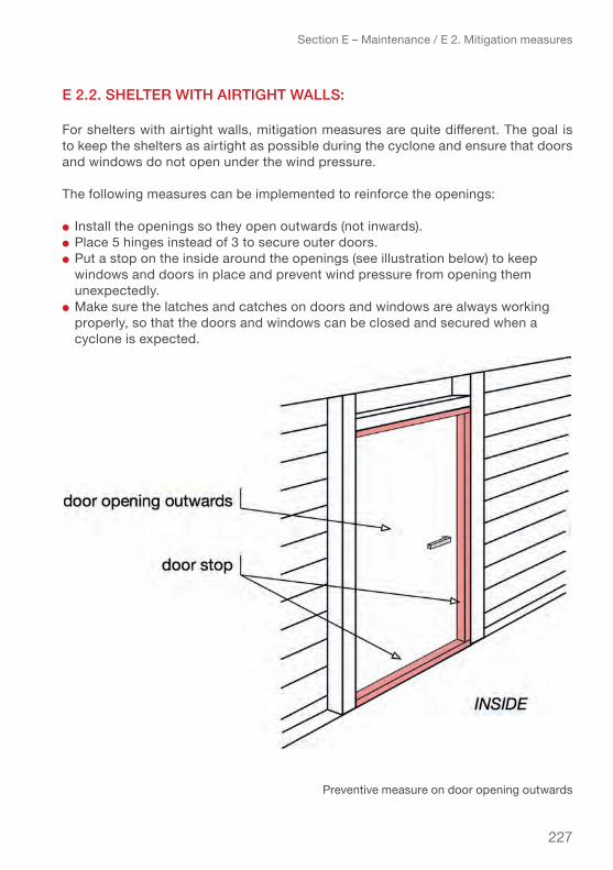
227
e 2.2. Shelter with Airtight wAllS:
For shelters with airtight walls, mitigation measures are quite different. The goal is to keep the shelters as airtight as possible during the cyclone and ensure that doors and windows do not open under the wind pressure.
The following measures can be implemented to reinforce the openings:
● Install the openings so they open outwards (not inwards).● Place 5 hinges instead of 3 to secure outer doors. ● Put a stop on the inside around the openings (see illustration below) to keep
windows and doors in place and prevent wind pressure from opening them unexpectedly.
● Make sure the latches and catches on doors and windows are always working properly, so that the doors and windows can be closed and secured when a cyclone is expected.
Section E – Maintenance / E 2. Mitigation measures
Preventive measure on door opening outwards

228
● If the doors open inwards, it is recommended to securely install 2–3 boards or bars across the door, so that it is more resistant to wind pressure (see drawing below). This measure is also a safety measure as it can prevent intruders from coming in.
Section E – Maintenance / E 2. Mitigation measures
Shutter with boards and brackets
Barring a door opening inwards

229
● If the windows open inwards, installing solid shutters on the outside of the windows will protect the window from flying debris and ensure that the house remains sealed.
The shutters can be made of various materials: wood, bamboo, plywood, galvanized metal sheet, etc.
e 2.3. reinforcement meASureS for the roof
If the CGI sheets are not sufficiently secured and/or the structural elements of the roof are not considered strong enough to resist a cyclone, the following measures can be applied to reinforce a roof for the cyclone season or directly when a cyclone warning has been issued. The aim of these measures is to particularly reinforce are-as of the roof where the wind pressure is the greatest, that is, the verges and eaves overhang of the roof, where the CGI sheets are most at risk of tearing off.
These measures will help hold the CGI sheets in place and reduce the risk of uplift for the whole roof. They cannot substitute for a well-built roof with CGI sheets securely fastened, as described in previous chapters.
The following three measures are presented:
● Support over the eaves overhang securely anchored to the ground.● Inverted-V support over the roof and securely anchored to the ground. ● Combination of the two measures.
Section E – Maintenance / E 2. Mitigation measures
Shutter with hinges and bolts
230
ReinfoRcement of eAves oveRhAng
Place a support across the roof at the eaves overhang, to prevent the lower part of the CGI sheet from lifting up under the wind pressure:
● Anything resistant which can be securely tied to the ground can be used as sup-port: wood, bamboo, metal bars, thick rope, cable, metal, wire, nylon strap.
● The support should be placed right above the outside wall, to be most effective. If they are placed too close to the eaves of the roof, they will not perform very well.
● Fix the support well at the edges of the roof, so it will not slip or slide off the roof. ● The support should be firmly tied to and anchored to the ground with means
such as:▹ “ballast anchors” such as blocks / stones or other heavy objects placed above the ground (the heavier the object the stronger the anchoring)▹ blocks / stone / heavy objects buried deep into the ground (the larger the object and the deeper buried the stronger the anchoring)▹ spiral / screw anchors or mechanical percussion driven ground anchors (resistance depending on size and type of anchor)
Section E – Maintenance / E 2. Mitigation measures
the reinforcement measures presented in this chapter can also be applied to roofs made of other materials, such as thatch, palm leaves etc. to reduce risk of uplift and damage.
Whatever measures applied, the effectiveness of the method depends highly on the resistance of the support itself (look to use strong materials) and the performance of the anchoring system. Different methods of anchoring are presented in the following chapter.
The supports can also be anchored to the structure itself, if the structure is well-built and heavy enough to withstand the wind pressure.
Page 231: Jamaica, hurricane Gustav, 2008: Barbed wire are placed over the CGI sheets at various places to prevent them from uplifting in preparedness for the passage of hurricane
Gustav. The barbed wire is fixed to the corner post and anchored in the ground.

231
Section E – Maintenance / E 2. Mitigation measures
Supports placed over the eaves on a gable roof with different types of anchors
gable roof:

232
ReinfoRcement of whole Roof
Place supports in shape of an “inverted-V” on the roof and firmly secure them to the ground to keep the roof in place under the wind pressure.
● Anything resistant which can be securely tied to the ground can be used as support: wood, bamboo, thick rope, cable, metal, wire, nylon strap.
If the materials are limited, it is recommended to place the inverted-V supports at the edges (verges) of the roof, where the pressure is greatest. the inverted-v supports placed in the central part of the roof help maintain the Cgi sheets of the ridge (ridge cap) but are less important than those close to the edges (verge).
Section E – Maintenance / E 2. Mitigation measures
Supports placed over the eaves on a hipped roof with different types of anchors
hipped roof:
This reinforcement measure can be implemented quickly and quite easily on any type of roof, with very little cost, using available materials. The performance will of course depend on the type and quality of support materials and anchoring used.
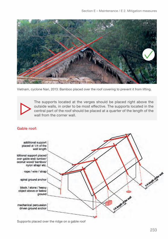
233
Section E – Maintenance / E 2. Mitigation measures
The supports located at the verges should be placed right above the outside walls, in order to be most effective. The supports located in the central part of the roof should be placed at a quarter of the length of the wall from the corner wall.
Supports placed over the ridge on a gable roof
gable roof:
Vietnam, cyclone Nari, 2013: Bamboo placed over the roof covering to prevent it from lifting.

234
comBineD ReinfoRcement of Roof AnD eAves PRotection
Combining the two reinforcement measures will deliver the best results because the area of increased wind pressure will be protected which includes the eaves, verge as well as the ridge.
Section E – Maintenance / E 2. Mitigation measures
Whatever measure used regardless of the roof shape, the stronger the wind, the stronger anchoring will be needed. It is possible to double or triple the number of anchors at each end of the reinforcements to increase the resistance.
Vietnam, 2006: Bamboo over a gable roof to reinforce it against uplift. Placing stones on the CGI roof is not recommended. (© Netherlands Red Cross)

235
Section E – Maintenance / E 2. Mitigation measures
Supports placed over the ridge and eaves on a gable roof
gable roof:
Supports placed over the ridge and eaves on a hipped roof
hipped roof:

236
Section E – Maintenance / E 2. Mitigation measures
The supports on verges and eaves should be placed right above the outside walls. The supports located over the central part of the roof should be placed at a quarter of the length of the wall from the corner wall for the gable roof and towards the ends of the ridge for the hipped roof.
Since the wind pressure is stronger on the edges of the roof, it is recommended to place the strongest anchors close to the edges of the roof, and the less effective anchors in the central part. To increase resistance it is possible to double or triple the number of anchors at each end of the support.
Jamaica, hurricane Dean, 2007: Roof with blocks on top of the CGI sheets at eaves and ridge. This is not recommended as they can fall during the storm creating damage and injuries. (French Red Cross)

237
e 2.4 tYpeS of AnchorS
To secure the roof reinforcement different types of ground anchors can be used in function of availability, the required performance and the soil condition.
● Ballast anchors like blocks or stones tied to the supports (above ground), can be used in any condition, but in general, are not heavy enough to hold down the roof in a strong storm.
● Buried blocks or stones covered with well compacted backfill can have a very good anchoring performance (a function of the volume and weight of the soil cov-ering the object). A minimum depth of 0.60 m is recommended to achieve strong anchoring. The larger the object, the greater the depth buried and the better compacted the backfill, the higher the anchor performance.
● Spiral and screw anchors have a good performance in sandy and clay soils. However they are very difficult to use in very hard or rocky and gravely soils.
● Mechanical or percussion driven earth anchors deliver the highest performance in most types of soil, if they can be driven to the required depth (difficult to install in very rocky or hard soils like laterite soils where they cannot be driven in deep enough) but perform less well in soils with a high component of clay.
Section E – Maintenance / E 2. Mitigation measures
Do not place heavy objects, such as blocks, tyres, sandbags etc., that are not securely held in place, on the roof! Such heavy objects can scratch or dent the CGI sheets, which will lead to faster corrosion and reduction of their service life. Under the effect of heavy wind or rain, these heavy objects can slip and fall off the roof and risk injuring people or causing damage.
all those anchors perform well under vertical ten-sion. If possible to install vertically then tendons do not need to be fixed at an angle but can be tied straight down from the supports on the roof.
anchor with helical screw

238
tiP: To achieve stronger anchoring use two or three anchors per support / anchor point.
Section E – Maintenance / E 2. Mitigation measures
Doubling anchors per support increases the performance
Page 239: Table 55
Singular roof anchors

239
eXAmPles of AnchoR PeRfoRmAnce in DiffeRent soils testeD By ifRc–sRu
The below examples of a screw anchor and a mechanical percussion driven ground anchor are taken from a study conducted by IFRC-SRU on ground anchors. They illustrate the difference in performance between different types of anchors as a function of the soil type.
As shown in the exemplary calculations of a shelter model (see chapter D 5) forces on hurricane straps connecting the rafters to the wall plate can easily be around 5000 N per rafter. This is approximately the dimension of the forces multiplied by the number of rafters (placed on the considered side of the roof) that the reinforcement measures should aim to resist!
Section E – Maintenance / E 2. Mitigation measures
model scRew AnchoR mechAnicAl PeRcussion DRiven gRounD AnchoR
photo
penetration depth into the ground
60 cm (2 ft) – depends on the screw anchor length
60–75 cm (2–2.5 ft)
Sandy soil good performance(resistance up to 3000 N)
Moderate performance (resistance of up to 1000 N)
Sandy clay soil good performance(resistance up to 2500 N)
High performance(resistance of up to 5000 N)
rocky, gravely soil
Barely possible to install High performance (resistance of up to 6000 N) difficult to install
hard silt soil not possible to install Very high performance (resistance of up to 8000 N) very difficult to install
rocky clay soil good performance(resistance up to 3000 N / 300 kg)
Moderate performance (resistance of up to 1000 N / 100 kg)

240
Section E – Maintenance / Practical Summary
prActicAl SummArY – Section e
Regular maintenance of the roof is important to:
● Reduce the risk of uplifting of the roof during a storm / cyclone.● Prevent damage and leakage of the roof covering.● Preserve the service life of the roof covering.
The roof frame and other structural elements (from foundation to roof), CGI sheets, fixings / fasteners, hurricane straps/ties, gutters should be checked regularly, espe-cially prior to the cyclone season.
mAintenAnce meAsuRes:
The following measures should be carried out to maintain the roofs performance:
● Rotten or damaged roof frame and structural elements should be replaced.● Loose fasteners should be tightened or if not possible additional fasteners added.● Small holes in the CGI sheets can be plugged with silicone, or covered with a
bitumen flashing tape or locally available alternate solutions.● CGI sheets with maximum of 5 % rust on their surface can be painted with a
zinc-rich paint.● Torn or cracked rubber washers or sealing washers should be replaced to avoid
leakage.● Gutters should be securely attached to the roof and cleaned regularly.
mitigAtion meAsuRes:
These measures can be carried out in preparation for forecasted cyclones, in order to reinforce the roof against uplift:
● In the case of airtight walls, seal the shelter / house by securely closing the open-ings, e.g., reinforcing the doors and windows, installing shutters.
● In the case that walls are not airtight (for example cladding with bamboo or palm leaf mats) it may be better to remove the wall cladding (and store in a safe place) to reduce the impact of wind forces on the structure and avoid potential damage of the structure.
● Supports, such as wood, bamboo, rope and wire can be placed over the roof and anchored to the ground (or to the structure if it is strong enough) to prevent the CGI sheets from tearing off or the roof from lifting.
● Different types of earth anchors can be used to secure the reinforcement sup-

241
Section E – Maintenance / Practical Summary
ports. The simplest and relatively effective solution is to tie the supports to stones or other heavy objects and bury them at least 60 cm in the ground.
It is highly recommended not to place any heavy objects, such as blocks, sandbags, or tyres on the roof as they can damage the CGI sheets and injure people.

Contact
ifRC-SRu Cité Henri Dunant 10, L-8095 Bertrange
Tél. 27 55 - 89 [email protected]
ifrc-sru.org