54" Galvanized Hyflo® Fan - Chore-Time
24
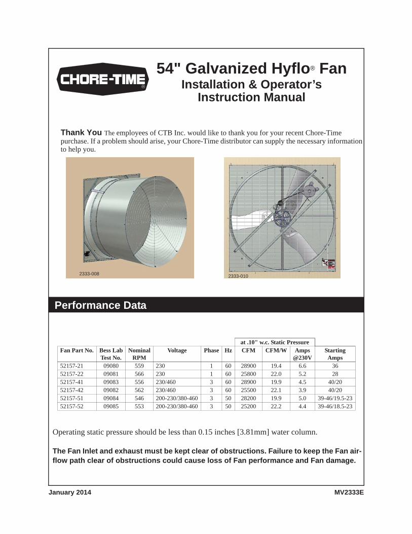
Thank You The employees of CTB Inc. would like to thank you for your recent Chore-Time purchase. If a problem should arise, your Chore-Time distributor can supply the necessary information to help you. 54" Galvanized Hyflo ® Fan Installation & Operator’s Instruction Manual 2333-008 2333-010 Performance Data at .10" w.c. Static Pressure Fan Part No. Bess Lab Test No. Nominal RPM Voltage Phase Hz CFM CFM/W Amps @230V Starting Amps 52157-21 09080 559 230 1 60 28900 19.4 6.6 36 52157-22 09081 566 230 1 60 25800 22.0 5.2 28 52157-41 09083 556 230/460 3 60 28900 19.9 4.5 40/20 52157-42 09082 562 230/460 3 60 25500 22.1 3.9 40/20 52157-51 09084 546 200-230/380-460 3 50 28200 19.9 5.0 39-46/19.5-23 52157-52 09085 553 200-230/380-460 3 50 25200 22.2 4.4 39-46/18.5-23 Operating static pressure should be less than 0.15 inches [3.81mm] water column. The Fan Inlet and exhaust must be kept clear of obstructions. Failure to keep the Fan air- flow path clear of obstructions could cause loss of Fan performance and Fan damage. MV2333E January 2014
-
Upload
khangminh22 -
Category
Documents
-
view
2 -
download
0
Transcript of 54" Galvanized Hyflo® Fan - Chore-Time
Thank You The employees of CTB Inc. would like to thank you for your recent Chore-Time purchase. If a problem should arise, your Chore-Time distributor can supply the necessary information to help you.
54" Galvanized Hyflo® FanInstallation & Operator’s
Instruction Manual
2333-008 2333-010
Performance Data
at .10" w.c. Static PressureFan Part No. Bess Lab
Test No.Nominal
RPMVoltage Phase Hz CFM CFM/W Amps
@230VStartingAmps
52157-21 09080 559 230 1 60 28900 19.4 6.6 3652157-22 09081 566 230 1 60 25800 22.0 5.2 2852157-41 09083 556 230/460 3 60 28900 19.9 4.5 40/2052157-42 09082 562 230/460 3 60 25500 22.1 3.9 40/2052157-51 09084 546 200-230/380-460 3 50 28200 19.9 5.0 39-46/19.5-2352157-52 09085 553 200-230/380-460 3 50 25200 22.2 4.4 39-46/18.5-23
Operating static pressure should be less than 0.15 inches [3.81mm] water column.
The Fan Inlet and exhaust must be kept clear of obstructions. Failure to keep the Fan air-flow path clear of obstructions could cause loss of Fan performance and Fan damage.
MV2333EJanuary 2014

Safety Information
Safety Information 54" Galvanized Hyflo® Fan
2 MV2333E
Carefully read all safety messages in this manual and on your equipment safety signs. Follow recommended precautions and safe operating practices. Keep safety signs in good condition. Replace missing or damaged safety signs.DANGER : Electrical HazardDisconnect electrical power before inspecting or servicing equipment. Ground all electrical equipment for safety. All electrical wiring must be done by a qualified electrician in accordance with local and national electric codes. Ground all non-current carrying metal parts to guard against electrical shock. With the exception of motor overload protection, electrical disconnects and over current protection are not supplied with the equipment.DANGER : Rotating Fan BladeKeep Hands away. Disconnect power before servicing. Fan may start automatically.Do not operate the Fan without the screens in place. Disregard to these things willcause serious injury including death.
Warranty
Chore-Time Egg Production Systems, a division of CTB, Inc., (“Chore-Time”), warrants each new CHORE-TIME® product manufactured by it to be free from defects in material or workmanship for one (1) year from and after the date of initial installation by or for the original purchaser. If such a defect is found by Chore-Time to exist within the one-year period, Chore-Time will, at its option, (a) repair or replace such product free of charge, F.O.B. the factory of manufacture, or (b) refund to the original purchaser the original purchase price, in lieu of such repair or replacement. Labor costs associated with the replacement or repair of the product are not covered by the Manufacturer.
Conditions and Limitations1.The product must be installed by and operated in accordance with the instructions published by the
Manufacturer or Warranty will be void.
2.Warranty is void if all components of the system are not original equipment supplied by the Manufacturer.
3.This product must be purchased from and installed by an authorized distributor or certified representative thereof or the Warranty will be void.
4."Malfunctions or failure resulting from misuse, abuse, mismanagement, negligence, alteration, accident, or lack of proper maintenance, or from lightning strikes, electrical power surges or interruption of electricity shall not be considered defects under the Warranty. Corrosion, material deterioration and/or equipment malfunction caused by or consistent with excessive additions or application of chemicals, minerals, sediments or other foreign elements with the product shall not be considered defects under the Warranty."
5.This Warranty applies only to systems for the care of poultry and livestock. Other applications in industry or commerce are not covered by this Warranty.
Chore-Time shall not be liable for any Consequential or Special Damage which any purchaser may suffer or claim to suffer as a result of any defect in the product. “Consequential” or “Special Damages” as used herein include, but are not limited to, lost or damaged products or goods, costs of transportation, lost sales, lost orders, lost income, increased overhead, labor and incidental costs and operational inefficiencies.THIS WARRANTY CONSTITUTES THE MANUFACTURER’S ENTIRE AND SOLE WARRANTY AND THIS MANUFACTURER DISCLAIMS ANY AND ALL OTHER WARRANTIES, INCLUDING, BUT NOT LIMITED TO, EXPRESS AND IMPLIED WARRANTIES AS TO MERCHANTABILITY, FITNESS FOR PARTICULAR PURPOSES SOLD AND DESCRIPTION OR QUALITY OF THE PRODUCT FURNISHED HEREUNDER.Chore-Time Distributors are not authorized to modify or extend the terms and conditions of this Warranty in any manner or to offer or grant any other warranties for CHORE-TIME® products in addition to those terms expressly stated above. An officer of CTB, Inc. must authorize any exceptions to this Warranty in writing. Chore-Time reserves the right to change models and specifications at any time without notice or obligation to improve previous models.

Tools Needed and Supplies
3/8" socket½" socket or wrenchSide cuttersLevel5/32" allen wrench (unassembled)
1/4" nut driverMotor power cordWire nuts / terminalsOptional screw hook installation tool (CTB part number 13150-1)Caulking
New Installation Planning
54" Galvanized Hyflo® Fan Tools Needed and Supplies
MV2333E 3
Framing
56-1/2" [143.51cm]
8" [20.32cm] Minimum
43" [109.22cm]
3-3/4" [9.5cm]
64"
[162
.6cm
]
13.5" [34.3cm]
2333-001
Important! Fan mounting surface must be flat.
Planning the layout of the spacing between Fans is very important. Spacing too close together will cause interference between the discharge Cones.
Outside Wall
3-1/2"[8.89cm] Min. if Cone Clips are used.
"X" =58-3/4" [149.23cm] MinimumFlat Mounting Surface Required
XX
(See page 13)
58-5
/8"
[148
.908
cm] S
quar
e
Minimum WallThickness 4.5" [11.43cm]

Minimum Rough Opening Size
51-5/8" [131.128cm]min. Rough Opening
57-1
3/16
" [14
6.84
4cm
]B
etw
een
Mou
ntin
g H
oles
Typ
.
14-5/32" [35.986cm] TypicalMounting Hole Spacing
56-1
/2" [
143.
51cm
]M
ax. R
ough
Ope
ning
Sq.
Installation
Minimum Rough Opening Size 54" Galvanized Hyflo® Fan
4 MV2333E
Attaching Fan Posts (For bulk packed Fans only)
(8282) 5/16 Car.
(8490) 5/16 Serrated
Corner Support
Flange Nut
Shroud Drain Hole
Bolt
Apply Fan Description Decalon Shroud as shown. (In Parts Pkg.)

54" Galvanized Hyflo® Fan Installation
MV2333E 5
Bottom Shelf Installation
(51039) 1/4 Lag Screw
If the Shelf is too long
Center ofBottom Shelf
Center of Rough Opening
Bottom Flange
Trim equal amounts from both ends.
Outside of House
Tighten until Snug only. Do not Deform the Bottom Shelf.)
(Do not overtighten Lag Screws.
Installation 54" Galvanized Hyflo® Fan
6 MV2333E
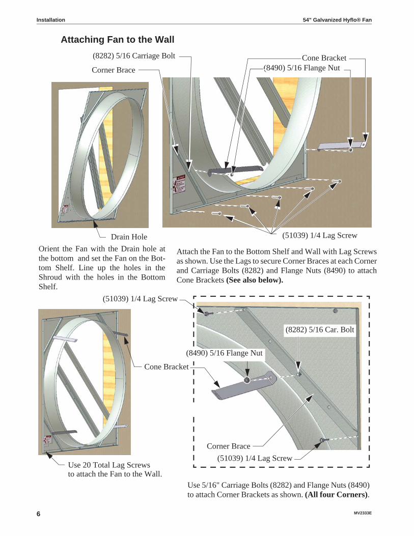
Attaching Fan to the Wall
Orient the Fan with the Drain hole at the bottom and set the Fan on the Bot-tom Shelf. Line up the holes in the Shroud with the holes in the Bottom Shelf.
Use 20 Total Lag Screwsto attach the Fan to the Wall.
Drain Hole
(51039) 1/4 Lag Screw
(51039) 1/4 Lag Screw
(8282) 5/16 Car. Bolt
Corner Brace
(8490) 5/16 Flange NutCone Bracket(8282) 5/16 Carriage Bolt
Corner Brace
Cone Bracket
Use 5/16" Carriage Bolts (8282) and Flange Nuts (8490) to attach Corner Brackets as shown. (All four Corners).
Attach the Fan to the Bottom Shelf and Wall with Lag Screws as shown. Use the Lags to secure Corner Braces at each Corner and Carriage Bolts (8282) and Flange Nuts (8490) to attach Cone Brackets (See also below).
(8490) 5/16 Flange Nut
(51039) 1/4 Lag Screw

54" Galvanized Hyflo® Fan Installation
MV2333E 7
Atta
chin
g M
otor
Sup
port
Bra
cket
Indi
vidu
ally
Pac
ked
Fan
Mod
els
Rot
ate
the
Mot
or S
uppo
rt B
rack
et in
to th
e up
right
pos
ition
by
rem
ovin
g th
e U
pper
Car
riage
Bol
t and
Nut
, and
loos
enin
g th
e L
ower
Bol
t and
Nut
.
(828
2) 5
/16
Car
riage
Bol
ts&
(849
0) 5
/16
Flan
ge N
uts
Atta
ch th
e M
otor
Sup
port
Bra
cket
to th
e Po
sts
with
5/
16 C
arria
ge B
olts
(828
2) a
nd 5
/16
Flan
ge N
uts (
8490
) .
Rem
ove
Upp
er C
arria
ge B
olt
Mot
or B
rack
etLo
osen
Car
riage
Bol
t

Installation 54" Galvanized Hyflo® Fan
8 MV2333E
Attaching Drive Assembly (Bulk Packed Fans only)Remove the Drive Assembly from the box and attach to the Posts with (4) 5/16 Carriage Bolts and (4) 5/16 Flange Nuts. Note that the Nuts go outside the Posts.
(8490) 5/16 SerratedFlange Nut
(8282) 5/16 Car. Bolt
(8490) 5/16 SerratedFlange Nut
Attaching the Fan Blade (Bulk Packed Fans Only)Apply Anti-Seize (included in parts package) to the Driven Shaft. Install the Fan Blade Flush with the end of the Shaft as shown with a 1/8 Key (Included in parts package)
1/8 Key
Blade Flush with end of Shaft
to 290 - 300 IN LBS. Torque both Blade Set Screws

54" Galvanized Hyflo® Fan Installation
MV2333E 9
Attaching the Motor
(8282) 5/16 Car. Bolts& (8490) 5/16 Flange Nuts
Remove the Motor from the Crate and attach it to the Motor Support Bracket with (4) 5/16 Carriage Bolts and (4) 5/16 Flange Nuts as shown.
(8282) 5/16 Car. Bolts
(8490) 5/16 Flange Nuts
Motor Sheave Installation (Bulk Packed Fans Only)
1/4" Key Supplied(Taped to Motor)
Motor Sheave
Apply Anti-Seize to Shaft and torqueSet Screw to 150-165 IN-LBS.
Align Motor Sheave withDriven Sheave
Align Motor Sheave with the Sheave on the Tensioner and attach as shown.
[16.9-18.6 NM]

Installation 54" Galvanized Hyflo® Fan
10 MV2333E
Belt Installation
TensionerSheave
DrivenSheave
MotorMotor
Belt
Caution: Make sure that the Belt does notRub the Motor Bracket.
Sheave
Cone Assembly and Installation
C-Shaped Drain Tab
Wrong! Cone Panel is upside down
Cone Panel
Slots in Cone Panel
Step 1: Lay a Cone Panel down (Drain Tab at the bottom and slots to the left) and Prop the end up (Slotted end) with a 2 x 4 board.

Step 2: Insert the Tabs of a second Cone Panel into the slots of the 1st Panel and Lay it down locking the two Panels together.
Step 3: Repeat Step 2 until all four Cone Panels are locked together.
Step 4: Stand the Panels up on edge and curl the Panels around making a Cone shape with the smaller diameter up. Insert the Tabs of the last Panel into the Slots of the 1st and allow the Cone to take its shape.
Step 5: Fasten the Cone Panels together with (4) 5/16 x .5" Hex Bolts (1839) and Flange Nuts (8490). Thread bolts from inside the finished Cone. Do not tighten down the Nuts at this time. Leave the Nuts loose until the Cone is attached to the Fan.
(8490) 5/16 Flange Nut
Holes nearest the Cone Panels edge
(1839) 5/16 Bolt
54" Galvanized Hyflo® Fan Installation
MV2333E 11
Installation 54" Galvanized Hyflo® Fan
12 MV2333E
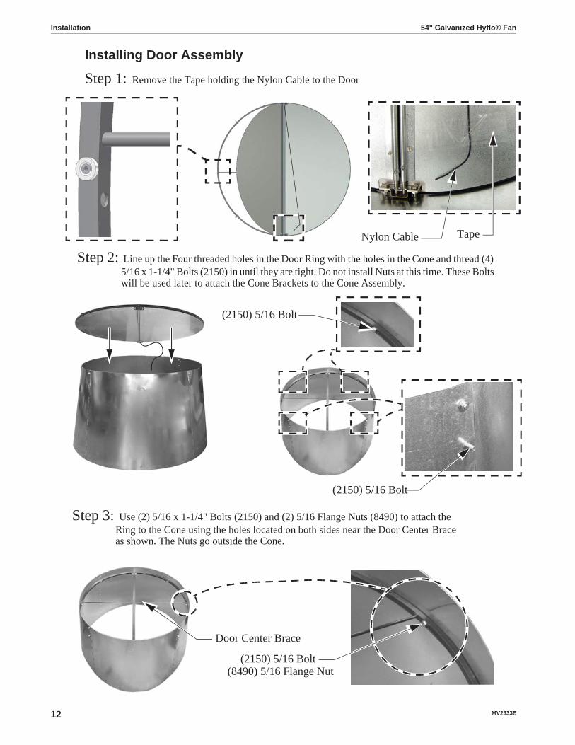
Installing Door Assembly
Step 2: Line up the Four threaded holes in the Door Ring with the holes in the Cone and thread (4) 5/16 x 1-1/4" Bolts (2150) in until they are tight. Do not install Nuts at this time. These Bolts will be used later to attach the Cone Brackets to the Cone Assembly.
Step 3: Use (2) 5/16 x 1-1/4" Bolts (2150) and (2) 5/16 Flange Nuts (8490) to attach the Ring to the Cone using the holes located on both sides near the Door Center Brace as shown. The Nuts go outside the Cone.
Nylon Cable Tape
(2150) 5/16 Bolt(8490) 5/16 Flange Nut
Door Center Brace
(2150) 5/16 Bolt
Step 1: Remove the Tape holding the Nylon Cable to the Door
(2150) 5/16 Bolt

54" Galvanized Hyflo® Fan Installation
MV2333E 13
Attaching the Door Stop Cable (Nylon Cable) and Grill.
Picture of Nylon Cable Secured
Nylon Cable
Grill Eyehook
(8282) 5/16 Car. Bolt
(8490) 5/16 Flange Nut
(8282) 5/16 Carriage Bolt
(8490) 5/16 Flange Nut
Top of Door
Step 1: Line up the Grill Eyehooks with the holes in the Cone. Thread the free end of the Nylon Cable through the bottom Grill Eyehook until it is flush with the Cone and secure it with a 5/16-18 Carriage Bolt (8282) and Flange Nut (8490) as shown.
Nylon Cable Flush with Cone
Step 2: Use 5/16 Carriage Bolts (8282) and Flange Nuts (8490) to fasten Grill to Cone at remaining 7 locations.

Installation 54" Galvanized Hyflo® Fan
14 MV2333E
Attaching ConeMounting the Cone and Door Assembly on the Fan requires at least two people. Pick up and orient the Cone with the Door Stop Cable attached at the top and rest the Cone on top of the Fan Orifice as shown. Attach the top of the Cone to the Cone Brackets with the Bolts that were previously threaded through the Ring and Cone and secure with 5/16 Flange Nuts (8490). Only hand tighten the Nuts at this time. Working around the Fan Orifice from inside the fan, in a circular motion Slide the Cone over the Fan Orifice. The Cone will Fit snug. Use the Bolts previously threaded through the Ring and Cone and the 5/16 Flange Nuts (8490) to secure the bottom of the Cone to the Fan as shown. Use a Level and rotate the Cone until the Door center rail is Vertical (See Figure). Now tighten all Hardware.
Door Stop CableCone Resting on Fan Orifice
(8490) 5/16Flange Nut
Cone Bracket
Door Center Rail Vertical
If the Cone will not slide over the Shroud Orifice easily, remove the three Flange Nuts from the Grill closest to the troubled area and push in on the Cone as shown. Fasten the Cone to the Bottom Cone Brackets with Flange Nuts (8490).
Cone Bracket
(8490) 5/16 Flange Nut
Remove Flange Boltsattaching Grill
Tighten the (4) 5/16 Flange Nuts that were installed to hold the Cone Panels together on page 11.

54" Galvanized Hyflo® Fan Installation
MV2333E 15
Installing Cone if Fan Spacing is 60"-64-1/2" on Center
Cut the legs from the Horizontal Grill Wire
Remove (8490) 5/16 Flange Nut(8490) 5/16 Flange Nut and attach Cone Clips (49504)
Door Spring Assembly
Door Center Brace
Spring Mounting Bracket
Step 1: Attach the Spring Mounting Bracket.
Step 2: Attach the Springs as shown.
Round endsDoor Spring Spring Mounting Bracket
Installation 54" Galvanized Hyflo® Fan
16 MV2333E
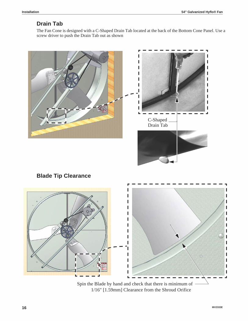
Drain TabThe Fan Cone is designed with a C-Shaped Drain Tab located at the back of the Bottom Cone Panel. Use a screw driver to push the Drain Tab out as shown
C-ShapedDrain Tab
Blade Tip Clearance
Spin the Blade by hand and check that there is minimum of 1/16" [1.59mm] Clearance from the Shroud Orifice

54" Galvanized Hyflo® Fan Installation
MV2333E 17
Motor Wiring1. Check that the electrical power
being supplied to
Drip LoopMotor Access Cover
Cord Clip
1/4" Lag Screw the Fan
matches the electrical Specifi-cations on the Fan and Motor Decals.
2. Remove the Motor Access Cover.
3. Install an electrical disconnect within reach of each Fan installed.
4. Connect the cord to the motor according to the wiring dia-gram on the motor. Verify that the motor is connected for counter clockwise rotation (viewing the back of the motor, opposite the shaft end.)
5. Follow local, state, and national electrical codes for wiring. Cut out one section of the Screen to route the cord out of the Fan: This will allow for the Screen to be removed without interfer-ing with the Cord.
6. Attach the cord to the Wall using a Lag Screw and Cord Clip. Allow enough slack in the cord to form a "drip loop" for moisture to fall away from the cord and not into the motor
Caulking
Caulk all edges of the Bottom Shelf except forat Shroud Drain Hole location.
Shroud Drain Hole(Do not Caulk Drain Hole Shut!)

Installation 54" Galvanized Hyflo® Fan
18 MV2333E
Assembling the screen
2. Install a spring (54480) in the upper left corner following steps A through D below. After Step D is complete go to step 3.
A) Slide a Spring (54480) over both Screen Panel Wires exactly as shown.
B) Rotate the Spring Counter-Clockwise until the end of the Spring snaps over the Side Panel Wire.
Snapped over Side Panel Wire
C) Slide and Pull Spring over Corner Panel Wire.
D) Twist Spring Clockwise until it is passed the outside wire and snapped firmly in place.
Spring snapped firmlybetween wires.
1. Fold the Screen Sides as shown. 3. Rotate the Screen in the direction shown installing a Spring at a second corner. Repeat for remaining Corners.
Install Springper steps
A-D below.
Keep RotatingInstalling a Spring
at each Corner.
Adjust Screen Panelsso they are as even
as possible
Slide
Pull
Corner Wire
54" Galvanized Hyflo® Fan Installation
MV2333E 19
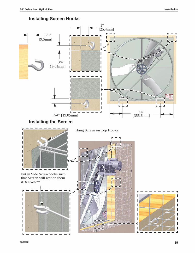
Installing Screen Hooks1"
3/4"
3/8"
3/4"14"
[9.5mm]
[25.4mm]
[19.05mm]
[355.6mm][19.05mm]
Installing the Screen
Hang Screen on Top Hooks
Put in Side Screwhooks suchthat Screen will rest on themas shown.
Maintenance
Maintenance 54" Galvanized Hyflo® Fan
20 MV2333E
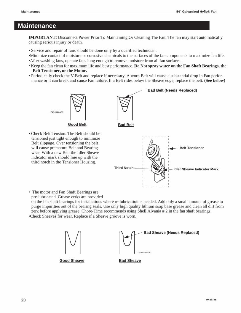
IMPORTANT! Disconnect Power Prior To Maintaining Or Cleaning The Fan. The fan may start automatically causing serious injury or death.
• Service and repair of fans should be done only by a qualified technician.•Minimize contact of moisture or corrosive chemicals to the surfaces of the fan components to maximize fan life.•After washing fans, operate fans long enough to remove moisture from all fan surfaces.• Keep the fan clean for maximum life and best performance. Do Not spray water on the Fan Shaft Bearings, the
Belt Tensioner, or the Motor.• Periodically check the V-Belt and replace if necessary. A worn Belt will cause a substantial drop in Fan perfor-
mance or it can break and cause Fan failure. If a Belt rides below the Sheave edge, replace the belt. (See below)
Bad BeltGood Belt
1747-054 04/03
Bad Belt (Needs Replaced)
• Check Belt Tension. The Belt should be tensioned just tight
Third Notch Idler Sheave Indicator Mark
Belt Tensioner
enough to minimize Belt slippage. Over tensioning the belt will cause premature Belt and Bearing wear. With a new Belt the Idler Sheave indicator mark should line up with the third notch in the Tensioner Housing.
• The motor and Fan Shaft Bearings are pre-lubricated. Grease zerks are provided on the fan shaft bearings for installations where re-lubrication is needed. Add only a small amount of grease to purge impurities out of the bearing seals. Use only high quality lithium soap base grease and clean all dirt from zerk before applying grease. Chore-Time recommends using Shell Alvania # 2 in the fan shaft bearings.
•Check Sheaves for wear. Replace if a Sheave groove is worn.
Bad Sheave
1747-053 04/03
Bad Sheave (Needs Replaced)
Good Sheave
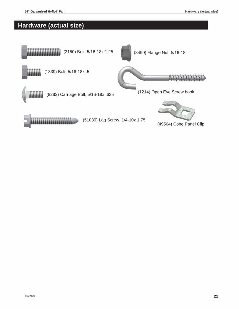
Hardware (actual size)
(2150) Bolt, 5/16-18x 1.25
(1839) Bolt, 5/16-18x .5
(8282) Carriage Bolt, 5/16-18x .625
(51039) Lag Screw, 1/4-10x 1.75
(8490) Flange Nut, 5/16-18
(49504) Cone Panel Clip
(1214) Open Eye Screw hook
54" Galvanized Hyflo® Fan Hardware (actual size)
MV2333E 21

Part
Num
bers
xx/x
x/xx
xx
1
2
4
5
6
8
42
16
29
14
15
18
2725
24
Dat
e of
Man
ufac
ture
Part
Num
ber
2
223332
3940
28
A-A
Det
ail A
-A
B-B
Det
ail B
-BD
etai
l C-C
Day
/Mon
th/Y
ear
C-C
D-D
7
Det
ail D
-D
33
934 34
38
33
34
E-E
Det
ail E
-E
312 34
3515
7
3334
18
3336
F-F
Det
ail F
-F33
10
11
20
21
3017 3334
3723
41
26 13
31
Part Numbers 54" Galvanized Hyflo® Fan
22 MV2333E

Part Numbers (Itemized)
54" Galv. Hyflo® Fan Part Numbers 52157-XXItem Part Description Part No. Models-XX
1 Motor, 1.5 H 1-60-230 50496 -21Motor, 1.5 H 1-60 230 1725 rpm 49903 -22Motor, 1.5 H 3-60/50-200-230/460V 1725/1425 rpm 48608 -41,-42,-51,-52
2 Post, Fan 52079 All3 Bearing, 1" Pillow Block 50553 All4 Bearing Support, Idler Drive 48395 All5 Motor Support, Idler Drive 48396 All6 Shroud, Fan 51018 All7 Support, Corner 52078 All8 Sheave, AK94 x 1.00 Bore 40274 -21,-22,-41,-42
Sheave, AK84-1.00 Bore 28143 -51,-529 Sheave, AK30 3" O.D. 5/8 Bore 8773 -21,-22,-41,-42
Sheave, 3.25 O.D. (AK32) 48504 -51,-5210 Shaft, 1" x 11.97 52083 All11 Blade, Energy Effecient 52111 -22,-42,-52
Blade, HI Cap 52176 -21,-41-,5112 Tensioner Support 48394 All13 Tensioner Assembly (with Idler) 48429 All14 54" Fan Shelf 52082 All15 54" Cone Panel 52110 All16 Screen, 56x56x12.35 (2 x 4 mesh) 48794 All17 Grill, 64" O.D. 49501 All18 Key, 1/4" Sq. x 1.13 2419-2 All19 Cone Clip (See Page 14) 49504 Optional20 Support, Hyflo® Door Spring 49450 All21 Frame, 54" Hyflo®Door 51454 All22 Magnet, .125 x .50 Dia. 48427 All23 Door, 54" Hyflo® 52085 All24 Fan Door Pivot Plate 49598 All25 Cable Assembly 50618-4 All26 Idler with Bushings (For Repair) 50879 All27 Spring, Door Closing 49629 All28 Bracket, 54" Fan Cone Support 52080 All29 V-Belt, AX60 48541 -21,-22,-41,-42
V-Belt, AX59 48615 -51,-5230 Pop Rivet, SS 1/8 x .40 48936 All31 Screen Spring (Package of 4) 54480-4 All32 Bolt, 5/16-18 x 1-1/2 2150 All33 Nut, 5/16-18 Hx Flange 8490 All34 Bolt, Carriage 5/16-18 x .626 8282 All35 Lag Screw, 1/4 x 1-1/2 51039 All36 Bolt, 5/16-18 x .1/2" 1839 All37 Hook, Open Eye Screw 1214 All38 Key, 1/8 x 1" (Supplied with Motor) -- All39 Nut, 1/4-20 Serrated Flange 46460 All40 Bolt, 1/4-20 x 5/8" 2152 All41 Nut, 3/8 x 16 Serrated Flange 39-45692 All42 Bolt, 3/8 x 16 x 1.25 39-20414 All
54" Galvanized Hyflo® Fan Part Numbers (Itemized)
MV2333E 23

Part Numbers (Itemized) 54" Galvanized Hyflo® Fan
24 MV2333E
Made to work.Built to last.
Revisions to this ManualPage No. Description of Change18 Replaced Wire Ties with Springs for Screen Installation
Contact your nearby Chore-Time distributor or representative for additional parts and information.
CTB Inc.P.O. Box 2000 • Milford, Indiana 46542-2000 • U.S.A.
Phone (574) 658-4101 • Fax (877) 730-8825E-Mail: [email protected] • Internet: http//www.ctbinc.com
Printed in the U.S.A.