Theory of Periodically Specified Problems: Complexity and Approximabil ity
IEEE TRANSACTIONS ON ULTRASONICS, FERROELUSTRONICS, AND FREQUENCY CONTROL, VOL. 41, NO. I , JANUARY 19% 13
Coupled-Mode Analysis of Love Waves in a Filter Film with Periodically Corrugated Surfaces
Muhammad A. Hawwa and Omar R. Asfar, Senior Member, IEEE
Absiruct-Mode coupling of Love waves in an orthotropic thin film having periodically corrugated surfaces over an isotropic elastic half space is considered. Six modes are coupled by both surfaces by means of three simultaneous resonant conditions. On the basis of the weakness of the corrugations, the method of multiple scales is used to derive the coupled-mode equations. These equations together with relevant boundary conditions form a two-point boundary-value problem, which is solved numeri- cally. The filter frequency response of a corrugated film designed as a stop-band filter is calculated. Enhanced filter characteristics are achieved when tapered corrugations are imposed. A narrow pass-band filter is also designed. Its high quality factor presents the fascinating features that might be realized by including the periodic corrugations in the design of SAW devices.
I. INTRODUCTION
INCE their postulation in 1911 [l] , Love waves have S been of interest to researchers from different disciplines. Geophysicists were the first to study these waves for their importance in earthquake seismology [2]. Such waves also found applications in the area of nondestructive evaluation like for example the detection of surface flow [3].
As a type of surface acoustic waves, Love waves were a possible candidate to be utilized in ultrasonic signal process- ing. Tuan et al. [4]-[6] have investigated the excitation and tapping of Love waves in thin-film layers. Seshadri [7] has considered the interaction of Love modes in a thin film having a free surface with weak sinusoidal corrugation, deposited on a semi-infinite substrate of another elastically isotropic material, and compared the characteristics of their reflection with the corresponding results for Rayleigh waves. The idea of using periodic corrugations at waveguide boundaries gives the analysis and design of surface acoustic wave devices and their electromagnetic counterparts a new dimension. By means of these periodic corrugations, guided modes interact in the neighborhood of a certain resonant frequency by exchanging energy. The problem of two-mode interaction in grounded dielectric thin films having periodic interface corrugation was reviewed by Seshadri [SI, who presented five basic methods to analyze the modal interaction. Asfar [9] has studied the problem of six-mode interaction in a dielectric film waveguide with multiperiodic interface corrugations and calculated the filter response of the system for cases of uniform, tapered, and chirped corrugations.
Manuscript received February 24,1993, revised and accepted June 15, 1993. M. A. Hawwa is with the Department of Engineering Science and Mechan-
ics, Virginia Polytechnic Institute and State University, Blacksburg, VA 24061. 0. R. Asfar is with the Department of Electrical Engineering, University
of Science and Technology, Irbid, Jordan. IEEE Log Number 921 1585.
Surface acoustic wave devices have the advantage of a considerable reduction in size and weight over their electro- magnetic counterparts. This is due to the small wavelengths and low velocities of acoustic waves. In this paper, the propagation of Love waves in a thin orthotropic film, de- posited on an isotropic semi-infinite substrate is considered. Both the surface between the film and the substrate and the free outerface are periodically corrugated. Incorporating multiperiodic corrugations introduces new possibilities for mode coupling. This is due to the fact that the multiperiod- icity allows more resonant conditions to occur resulting in an intricate interaction picture at high operating frequencies where multimodes are eminently present. The problem is formulated in the format of the method of multiple scales [ 101, which is used to analyze the interaction of six propagating modes. Three incident modes and three reflected modes are coupled by both surface corrugations when three simultaneous resonant conditions occur. The analysis leads to the derivation of the coupled-mode equations. Imposing relevant end-point conditions satisfied by the coupled modes leads to a two-point boundary value problem, which is solved numerically by the fundamental matrix method [ 1 1 1 . The results are utilized for calculating the waveguide filter response in terms of the power reflection and/or transmission coefficient. The corrugated film is designed as a stop-band filter, whose characteristics are enhanced by introducing tapered corrugations. A narrow pass- band filter design with a high quality factor is also realized by means of a special arrangement of surface corrugations.
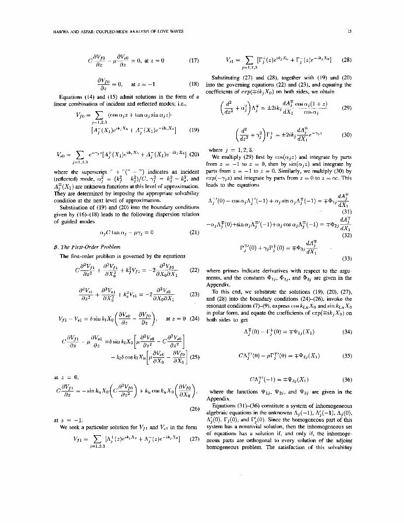
11. PROBLEM FORMULATION We consider the thin layer (film) with an orthotropic degree
of elastic symmetry deposited on the isotropic half-space (substrate) shown in Fig. 1. The interface between the film and the substrate and the Free outerface of the film have small periodic corrugations described in a Cartesian coordinate system (i, y, 2) by i = heSsink13, and 2 = h(-1 + E sin E,?), where and k , are, respectively, the wavenumbers of the interface and the outerface, h is the average thickness of the film, E is a small dimensionless parameter much smaller than unity and equal to-the ratio of the amplitude of the outerface corrugation to h, and 6 is a constant allowing for a different corrugation amplitude at the interface.
The subject under consideration is the propagation of monochromatic Love waves having a temporal variation in the form exp(-i&t̂ ), where 5 is the frequency of oscillation, and t^ is the time coordinate. In the sequel, dimensionless
0885-3010/93$03.00 0 1993 IEEE
14 IEEE TRANSACTIONS ON ULTRASONICS, FERROELECTRONICS, AND FREQUENCY CONTROL, VOL. 41, NO. I , JANUARY 1994
b t
Fig. 1 . Waveguide geometry
quantities (without the carets) are used by introducing 5 and h as reference quantities.
The horizontally polarized motion in the film and the substrate are governed by
azv, azv, -+- + k?V, = 0 a x ~ a z 2
where the subscripts f and s indicate film and substrate, respectively, V ( x , z ) is the y-component of displacement, k f = rjk(bf/&)+ and IC, = 5h(bs / f i , )+ represent the wavenumbers of bulk waves, C = &4/& is the ratio of the elastic constants of the orthotropic material, f i , is the shear modulus of the substrate material, and 6 is the material density.
The boundary conditions are the continuity of the displace- ment component and the stress vector at the interface, and the vanishing of stress vector at the outerface. These read
Vf = V,, at z = ~6 sin klx (3)
at z = ~ S s i n k l x ,
avf 0, at z = -1 + &sinkux (5 ) -n, + C-n, = Wf d X az
where p = f i s / & ~ , and n, and n, are the components of the local outward-pointing unit normal.
A solution of the system (1)-(5) in the form of a first-order straightforward asymptotic expansion is found to break down in the neighborhood of the resonant frequencies given by
(6)
where I C , and k,, are the wavenumbers of two interacting modes. In this study, the interaction of six modes is considered. These modes can be coupled by both corrugated surfaces in different ways [12]. To ensure a strong interaction, we select three simultaneous resonant conditions: a condition on two
km F kn = kl , ,
codirectional modes, another on two contradirectional modes, and a Bragg condition. These are
kl - k3 = k, + &U, (7)
2k3 = k , + E C T ~ (9)
Here C T ~ , 0 2 , and ~3 are detuning parameters introduced to quantitatively describe the nearness to resonance.
Uniformly valid asymptotic expansions in the neighborhood of resonance will be obtained in the next section by using the method of multiple scales [lo].
111. METHOD OF ANALYSIS
We seek first-order perturbation expansions for Vf and V, in powers of E in the form
vf(x ,z) = VfO(z,xO,xl, * * .) +EVfl(z,xO,Xl,. . -) + . .. (10)
V,(x,z) = V,o(z, xo, XI,. . .) + EVs1(z7 XO,Xl,. . .) + . . . (11)
where X O = x is a short scale of the order of the wavelength in the guide and XI = E X is a long scale which characterizes the amplitude and phase modulations due to the surface corrugations. Using the chain rule, we can write the derivatives with respect to x in terms of X O and X I as
a a d - _ _ = +e-+ . . . ax 8x0 ax, (12)
Substituting (10)-(13) into (l)-(S), expanding Vf at z = ~6s inklXo in a Taylor series around z = 0, V, at z = -1 +~s ink ,Xo around z = -1, and equating the coefficients of EO and E , on both sides, we have two sets of problems. They are the zeroth-order and the first-order problems discussed below.
A . The Zeroth-Qrder Problem The zeroth-order field equations are given by
(16) Vjo - VSo = 0, at z = 0
HAWWA AND ASFAR: COUPLED-MODE ANALYSIS OF LOVE WAVES
avfo w 9 0
dZ az C--p-=O, a t z = O
Substituting (27) and (28), together with (19) and (20) d V f o = O , a t z z - 1 (18) into the governing equations (22) and (23), and equating the
coefficients of ezp(TikjX0) on both sides, we obtain az Equations (14) and (15) admit solutions in the form of a
(29) linear combination of incident and reflected modes; i.e., dA’f COS aj (1 + Z )
(-$+a?)AT = f 2 i k . 3 .J dX1 cosaj v ~ O = (cosajz + tan aj sin a j z ) .
j=1,2,3
vs0 = e-YJZIAT(Xl)eikJ*‘O + A ~ ( X l ) e - i h ~ X o ] (20) j = 1,2,3
where the superscript ’‘ + ”(” - ”) indicates an incident (reflected) mode, a: = ( k ; - k;)/C, 7; = - kz , and AT ( X I ) are unknown functions at this level of approximation. They are determined by imposing the appropriate solvability condition at the next level of approximation.
Substitution of (19) and (20) into the boundary conditions given by (1 6)-( 18) leads to the following dispersion relation of guided modes
(21) ajC tan a3 - p-yj = 0
B . The First-Order Problem The first-order problem is governed by the equations
where j = 1,2,3. We multiply (29) first by cos(ajz) and integrate by parts
from z = -1 to z = 0, then by sin(ajz) and integrate by parts from z = -1 to z = 0. Similarly, we multiply (30) by ezp(-yjz) and integrate by parts from z = 0 to z = 00. This leads to the equations
(33)
(22) where primes indicate derivatives with respect to the argu- ments, and the constants @ 1 j , @ 2 j , and @3j are given in the Appendix.
a2vS1 a2vs1 @VSO To this end, we substitute the solutions (19), (20), (27), (23) and (28) into the boundary conditions (24)-(26), invoke the
resonant conditions (7)-(9), express cos kl,,Xo and sin kl,,Xo in polar form, and equate the coefficients of ezp(TikjX0) on
8% a2vfl + k 2 v a z 2 + ax,2 f f1 = -2axoaxl
az2 + 2 + k,2Kl = -2-
C-
ax, axoaxl
V f , - Vsl = S sin klX0 (’2’ - - - ’2) 1 at = 0 (24) both sides to get
CA,r’(-l) = ~ K i ? 3 ~ ( X 1 ) (36)
where the functions 9 1 j , 9 2 j , and Ki?3j are given in the
at z = 0,
- C- - -sin k,Xo dz
Appendix. Equations (3 1 H 3 6 ) constitute a system of inhomogeneous
(26) algebraic equations in the unknowns Aj(-l), Ai(-l), Aj(O), A$(O), rj(O), and ri(0). Since the homogeneous part of this system has a nontrivial solution, then the inhomogeneous set of equations has a solution if, and only if, the inhomoge- neous parts are orthogonal to every solution of the adjoint homogeneous problem. The satisfaction of this solvability
at z = -1. We seek a particular solution for Vfl and Vsl in the form
Vf1 = [ A T ( z ) e z k ~ x o + A ~ ( Z ) ~ - Z ~ J ~ ~ 1 (27) j=1,2,3
16 IEEE TRANSACTIONS ON ULTRASONICS, FERROELECTRONICS. AND FREQUENCY CONTROL, VOL. 41, NO. 1, JANUARY 1994
(consistency) condition leads to the derivation of the following I
coupled-mode equations 0 9 -
0 8 -
0 7 -
dX1 0 6 -
c: 0 5 -
ell- d A t - C13A3 + e -zgiXi - ~ ~ ~ ~ ; ~ - z m X i = 0 (37)
(38) dA+ dX1
C 2 2 L - C24Ale-a01X1 = 0
dA; C33- - C31Afe2u1X1 - C36A3e-203X1 = 0 (39) dXi I 8 I805 1 8 1 I815 1 8 2 1 8 2 3 1 8 3
Frequency Hz SLOG
dA- dXi corrugations.
c112 - C13Ageia1X1 - C15A;eia2X1 = 0 (40) Fig. 2. Power reflection coefficient R for a stop-band filter with uniform
IV. NUMERICAL EXAMPLES
A waveguide with p s / p f = 1.5, p,25, C= 2 is selected. Numerical solution of the dispersion relation (21) leads to the determination of the simultaneous resonant condition at w = 1 813 020 Hz, corresponding to kl = 11.176, k2 = 9.282,and k3 = 3.726. Next, we calculate the filter response of two different designs of corrugated films.
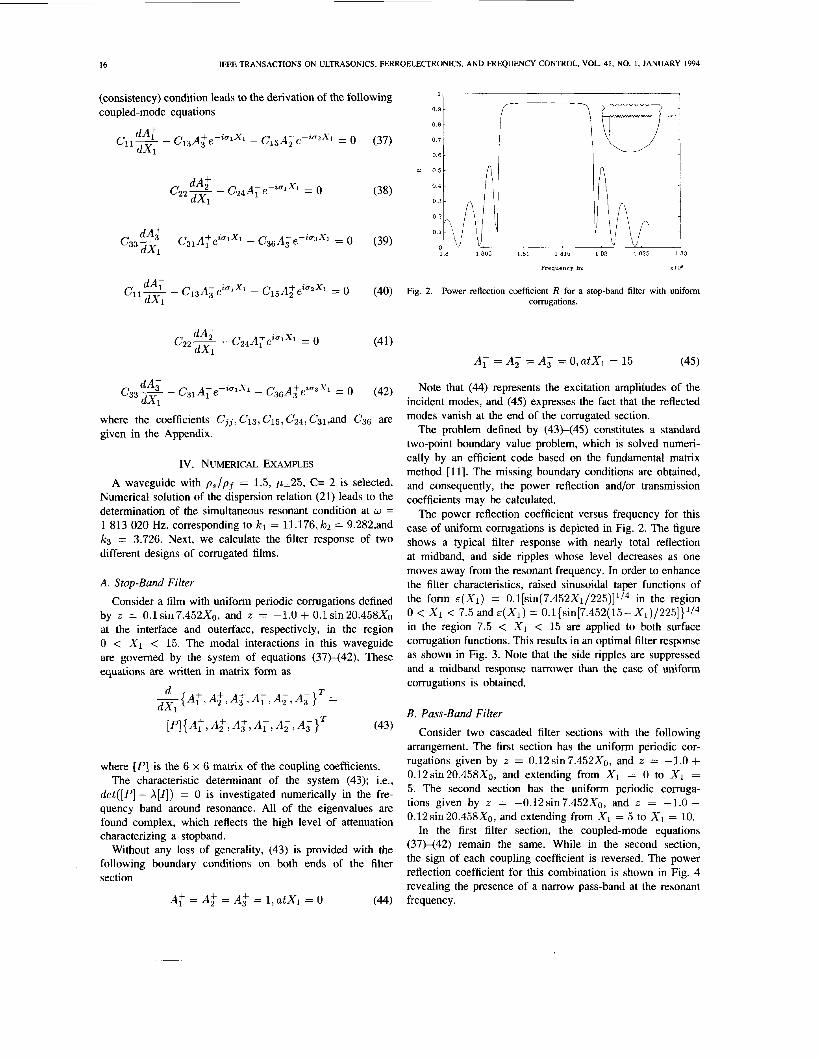
A . Stop-Band Filter
Consider a film with uniform periodic corrugations defined by z = O.lsin7.452X0, and z = -1.0 + O.lsin20.458Xo at the interface and outerface, respectively, in the region 0 < X1 < 15. The modal interactions in this waveguide are governed by the system of equations (37)-(42). These equations are written in matrix form as
d T -{A:, A;, A;, A,, A;, A ; } = dX1
I P I { A : , A ~ , A ~ , A 1 , A ~ , A 3 } T (43)
where [PI is the 6 x 6 matrix of the coupling coefficients. The characteristic determinant of the system (43); i.e.,
det([P] - X [ I ] ) = 0 is investigated numerically in the fre- quency band around resonance. All of the eigenvalues are found complex, which reflects the high level of attenuation characterizing a stopband.
Without any loss of generality, (43) is provided with the following boundary conditions on both ends of the filter section
(44) A: =A; = A $ = i l a t x l = o
Note that (44) represents the excitation amplitudes of the incident modes, and (45) expresses the fact that the reflected modes vanish at the end of the corrugated section.
The problem defined by (43)-(45) constitutes a standard two-point boundary value problem, which is solved numeri- cally by an efficient code based on the fundamental matrix method [ 1 11. The missing boundary conditions are obtained, and consequently, the power reflection and/or transmission coefficients may be calculated.
The power reflection coefficient versus frequency for this case of uniform corrugations is depicted in Fig. 2. The figure shows a typical filter response with nearly total reflection at midband, and side ripples whose level decreases as one moves away from the resonant frequency. In order to enhance the filter characteristics, raised sinusoidal taper functions of the form &(XI) = O.l[sin(7.452X1/225)]~/~ in the region 0 < X1 < 7.5 and .(XI) = O.l{~in[7.452(15-X1)/225]}~/~ in the region 7.5 < X1 < 15 are applied to both surface corrugation functions. This results in an optimal filter response as shown in Fig. 3. Note that the side ripples are suppressed and a midband response narrower than the case of uniform corrugations is obtained.
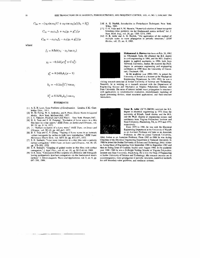
B. Pass-Band Filter Consider two cascaded filter sections with the following
arrangement. The first section has the uniform periodic cor- rugations given by z = 0.12sin7.452X0, and z = -1.0 + 0.12sin20.458X0, and extending from X1 = 0 to X1 = 5. The second section has the uniform periodic cormga- tions given by z = -0.12sin7.452X0, and z = -1.0 - 0.12 sin 20.458X0, and extending from X1 = 5 to X1 = 10.
In the first filter section, the coupled-mode equations (37)-(42) remain the same. While in the second section, the sign of each coupling coefficient is reversed. The power reflection coefficient for this combination is shown in Fig. 4 revealing the presence of a narrow pass-band at the resonant frequency.
HAWWA AND ASFAR: COUPLED-MODE ANALYSIS OF LOVE WAVES 17
1 , I
0' I 1.81 1.811 1.812 1.813 1.814 1.815 L B I G 1.817
Frequency Hz ~ 1 0 0 Frequency HZ 1106
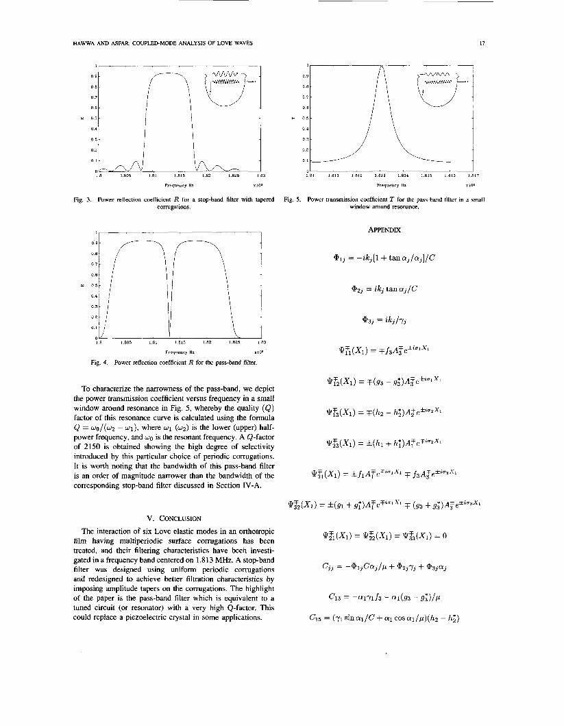
Fig. 3. Power reflection coefficient R for a stop-band filter with tapred Fig. 5. Power transmission coefficient T for the pass-band filter in a small corrugations. window around resonance.
I I APPENDIX
Frequency Hz Yl06
Fig. 4. Power reflection coefficient R for the pass-band filter.
Q72(Xl) = ~ ( 9 3 - gi)A$efialX1 To characterize the narrowness of the pass-band, we depict
the power transmission coefficient versus frequency in a small window around resonance in Fig. 5 , whereby the quality (Q) factor of this resonance curve is calculated using the formula Q = wo/(w2 - wl), where w1 (w2) is the lower (upper) half- power frequency, and WO is the resonant frequency. A Q-factor of 2150 is obtained showing the high degree of selectivity introduced by this particular choice of periodic corrugations. It is worth noting that the bandwidth of this pass-band filter is an order of magnitude narrower than the bandwidth of the corresponding stop-band filter discussed in Section IV-A.
@73(X1) = ~ ( h 2 - h~)AzefzuaX1
@$3(X1) = f ( h l + h;)AFeTiUzX1
QZ(X1) = fflATeTZulX1 F f3A$e*Z03S1
@&(XI) = f(g1 + g;)ATeFzulX1 T (93 + 9 3 * ) ~ 3 f e * ~ ~ 3 ~ 1
V. CONCLUSION The interaction of six Love elastic modes in an orthotropic
film having multiperiodic surface corrugations has been treated, and their filtering characteristics have been investi- gated in a frequency band centered on 1.8 13 MHz. A stop-band
and redesigned to achieve better filtration characteristics by imposing amplitude tapers on the corrugations. The highlight
tuned circuit (or resonator) with a very high Q-factor. This could replace a piezoelectric crystal in some applications.
Q$~(XI) = QZz(X1) = Q$3(X1) = o
c,, = -@13Caj/P + a 2 3 7 3 + @33ff3 filter was designed using uniform periodic corrugations
of the paper is the pass-band filter which is equivalent to a c 1 3 = -alylf3 - al(g3 - gi)/p
CIS = (71 sinal/C + a1 cosal/p)(hZ - h;J)
18 IEEE TRANSACTIONS ON ULTRASONICS, FERROELECTRONICS, AND FREQUENCY CONTROL, VOL. 41, NO. 1 , JANUARY 1994
C24 = -(72sina2/C+ a2coscu2/p)(hl + h;) [lo] A. H. Nayfeh, Introduction to Perturbation Techniques. New York: Wiley, 1981.
[ 111 0. R. Asfar and A. M. Hussein, “Numerical solution of linear two-point boundary-value problems via the fundamental matrix method,” Int. J . Num. Meth. Eng., vol. 28, pp. 1205-1216, 1989.
[I21 0. R. Asfar and A. H. Nayfeh, “The application of the method of multiple scales to wave propagation in periodic structures,” SIAM Review, vol. 25, no. 4, 1983.
c31 = a373fl + a3(gl + g ; ) / p
c 3 6 = -a373f3 - a 3 ( g 3 + g i > / p
where
aj tan a j )
hj = -O.SiaSC/~osaj
h5 = 0.5iSkukj/ COS aj
REFERENCES
[ l ] A. E. H. Love, Some Problems of Geodynamics. London, U.K.: C m - bridge Univ., 1911.
[2] W. M. Ewing, W. S. Jardetsky, and F. Press, Elastic Waves in Layered Media. New York: McGraw-Hill, 1957.
[3] I. A. Viktorov, Rayleigh and Lamb Waves. [4] H. S. Tuan and S. R. Ponamgi, “Excitation of Love waves in a thin
film layer by a line source,” IEEE Trans. on Sonics and Ultrason., vol.
[5] -, “Surface excitation of a Love wave,” IEEE Trans. on Sonics and Ultrason., vol. SU-19, pp. 4 4 2 4 3 , 1972.
[6] H. S. Tuan and C. P. Chang, “Tapping of Love waves in an isotropic surface waveguide by surface-to-bulk wave transduction,” IEEE Tram. Microwave Theory Tech., vol. MlT-20, pp. 472477, 1972.
[7] S. R. Seshadri, “Love wave interaction in a thin film with a periodic surface corrugation,” IEEE Trans. on Sonics and Ultrason., vol. SU-25, pp. 378-383, 1978.
[8] S. R. Seshadri, “Coupling of guided modes in thin films with surface corrugation,” J. Appl. Phys., vol. 63, no. 10, pp. RI 15-R146, 1988.
[9] 0. R. Asfar, “Calculation of filter response of a dielectric slab waveguide having multiperiodic interface corrugations via the fundamental matrix method,” J. Electromagnetic Waves and Applications, vol. 3, no. 8, pp. 697-709, 1989.
New York: Plenum,1967.
SU-19, pp. 9-14, 1972.
Muhammad A. Hawwa was born on Feb. 20, 1962 in Alhammah, Syria. He obtained the B.S. degree in civil engineering in 1984, and the M.S. (honors) degree in applied mechanics in 1986, both from Yarmouk University, Jordan. He received his Ph.D. degree in aerospace engineering and engineering mechanics in 1990 from the University of Cincin- nati, Cincinnati, OH.
In the academic year 1990-1991, he joined the University of Jordan as a lecturer at the Mechanical Engineering Department. In 1991-1992, he was a
visiting research associate at Jordan University of Science and Technology. Presently, he is working as a research scientist with the Department of Engineering Science and Mechanics at Virginia Polytechnic Institute and State University. His areas of interest include wave propagation in structures with applications to nondestructive evaluation, elastodynamic modeling of signal processing devices, smart structural applications, and fluid-structure interactions.
Omar R. Asfar (M’75-SM’89) received the B.S. degree in electrical engineering in 1971 from the university of Riyadh, Saudi Arabia, and the M.S. and the Ph.D. degrees in engineering science and mechanics from Virginia Polytechnic Institute and State University, Blacksburg, VA, in 1973 and 1975, respectively.
From 1975 to 1981, he was with the Electrical Engineering Department at the University of Riyadh as an Assistant Professor and later as an Associate Professor. In 1981 he joined Yarmouk University,
Irbid, Jordan as an Associate Professor. From 1982 to 1986 he was Acting Chairman of the Electrical Engineering Department at Yarmouk University. In 1988 he joined the Jordan University of Science and Technology, Irbid, Jordan as Acting Dean of Engineering from September 1986 to September 1987 and then as Acting Dean of Graduate Studies until August 1988. In the academic year 1988-1989 he was a Fulbright Visiting Scholar at Virginia Polytechnic Institute and State University, Blacksburg. He is now the Dean of Engineering at Jordan University of Science and Technology. His research interests are in electromagnetics, wave propagation in periodic structures, numerical methods for stiff boundary-value problems, and nonlinear systems.
Copyright © 2022 FDOKUMEN