lateral-torsional buckling of beams elastically restrained ...
Upload
khangminh22Category
view
0download
0
Buckling behavior of steel column with triangularly corrugated web
Sergey Kudryavtsev1,*
1Ural Federal University, Department of Building Structures and Soil Mechanics, Mira Street 17a, Yekaterinburg 620002, Russia
Abstract. The paper presents a study of behaviour of axially loaded columns that consist of two flanges and a thin triangularly corrugated web, connected by automatic welding. In the literature, the buckling behaviour of steel columns was dealt with mostly for members with plate webs. Researches of that problem for columns with corrugated webs were found out to be very limited. A parametric study is carried out for various column slenderness and corrugation densities. A general-purpose finite element analysis software ABAQUS was used. The corrugation densities adopted in this study represent practical geometries, which are commonly used for such structures in building practice. Plot showing the influence of section slenderness on value of reduction factor for lateral buckling is presented. It is determined that existing buckling curves poorly describe the dependence of the reduction factor on slenderness for axially compressed members with triangularly corrugated webs. Finally, recommendations were proposed for the design of pin-ended columns with corrugated webs at lateral buckling in accordance with numerical results.
1 Introduction Corrugated webs are often used in building practice to reduce metal consumption and increase the rigidity of the I-sections. Nowadays such structures are generally used as ceiling girders in multi-story apartment houses, large span roof girders in industrial and administrative buildings, etc. However, from such profiles, it is possible to produce also column compressed elements and the whole building frame – see fig. 1.
In the world practice sections with trapezoidal, sinusoidal and triangular corrugation profiles are most widely used. Triangularly corrugated webs have several advantages over others. For example, they do not require expensive equipment for the production and the webs could be thicker than sinusoidal ones and therefore could resist heavier loads. Through its profiled form, web exhibits enhanced shear stability and therefore eliminate the need for additional transverse stiffeners or thicker web plates. An original feature of I-sections with a corrugated web is the almost complete perception of the bending moment and longitudinal force by the flanges. Due to so-called “accordion effect” [1-3, 7] the normal stresses along the height of the web are significant just in narrow areas near the flanges and insignificant for most of the web height. This situation at first glance reduces * Corresponding author: [email protected]
© The Authors, published by EDP Sciences. This is an open access article distributed under the terms of the Creative Commons Attribution License 4.0 (http://creativecommons.org/licenses/by/4.0/).
MATEC Web of Conferences 279, 02007 (2019) https://doi.org/10.1051/matecconf/201927902007Building Defects 2018

the load-bearing capacity of the structure at buckling, but on the other hand, such structure can be considered as a lattice column in which corrugated web fulfils the lattice's role and possesses increased stability in the strong plane.
Fig. 1. (a) Frame structure of residential building with corrugated web beams and columns; (b) Considered column design scheme; (c) Cross section of column with corrugated web; (d) Geometrical parameters of corrugated web with triangular shaped corrugations.
Lateral buckling problem of compressed members was solved in 1757 by Euler [4]. He derived the theoretical solution for an axial force that a long, slender, ideal bar can carry without buckling. Practical experiments performed by Shanley in 1947 [4] have made a great contribution to the study of the inelastic buckling of columns. It was established that for stocky columns, the strength is governed by plastic "squashing". For inelastic buckling, the value of initial imperfections has the greatest importance what was noted by Calladine in 1973 [5].
Most research studies of structures with corrugated webs are devoted to various aspects of the bending elements and very few studies are devoted to axially compressed members. One of the first was performed by Fraser in 1956 [6]. He studied the interaction between the compressive flange and corrugated webs in multiweb beams, but its topic is similar to the study of columns since both structures involve the interaction between flange and the web when flange is under compression. Aravena and Edlund in 1987 [7] considered the combined effect of axial compression and shear and recommended formula to evaluate influence of axial force on shear capacity of corrugated web. Wang in 2003 [7] performed a series or full-scale tests and finite element analysis of axially compressed columns with tubular flanges and trapezoidally corrugated web.
The present paper deals with the elastic and inelastic buckling behaviour of steel columns with triangularly corrugated webs – see fig. 1. A numerical parametric study was carried out for pin-ended corrugated web columns. Various cases were considered including length, height of the column and the corrugation density expressed as a ratio between height and length of half-wave of corrugation. The software ABAQUS (2017) was used to carry out linear buckling analyses (LBA) and Riks analyses to obtain the elastic and inelastic critical axial forces for columns. Results compared with estimations of the currently available design guidance [3, 8-11].
(b)
l
P
bf t f t f
h w
h f
tw
f/2
Neutral axis
f
bw
a a a a
(c)
(d)
h
bf (a)
2
MATEC Web of Conferences 279, 02007 (2019) https://doi.org/10.1051/matecconf/201927902007Building Defects 2018
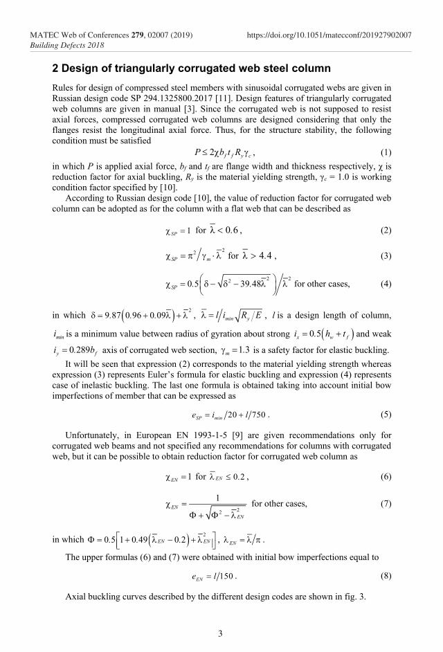
2 Design of triangularly corrugated web steel column Rules for design of compressed steel members with sinusoidal corrugated webs are given in Russian design code SP 294.1325800.2017 [11]. Design features of triangularly corrugated web columns are given in manual [3]. Since the corrugated web is not supposed to resist axial forces, compressed corrugated web columns are designed considering that only the flanges resist the longitudinal axial force. Thus, for the structure stability, the following condition must be satisfied
2 f f y cP b t R , (1) in which P is applied axial force, bf and tf are flange width and thickness respectively, χ is reduction factor for axial buckling, Ry is the material yielding strength, γc = 1.0 is working condition factor specified by [10].
According to Russian design code [10], the value of reduction factor for corrugated web column can be adopted as for the column with a flat web that can be described as
1SP for 60λ . , (2)
22SP m for 44λ . , (3)
2 220 5 39 48SP . .
for other cases, (4)
in which 29 87 0 96 0 09. . . , min yl i R E , l is a design length of column,
mini is a minimum value between radius of gyration about strong 0 5x w fi . h t and weak
0 289y fi . b axis of corrugated web section, 1 3m . is a safety factor for elastic buckling. It will be seen that expression (2) corresponds to the material yielding strength whereas
expression (3) represents Euler’s formula for elastic buckling and expression (4) represents case of inelastic buckling. The last one formula is obtained taking into account initial bow imperfections of member that can be expressed as
20 750SP mine i l . (5)
Unfortunately, in European EN 1993-1-5 [9] are given recommendations only for corrugated web beams and not specified any recommendations for columns with corrugated web, but it can be possible to obtain reduction factor for corrugated web column as
1EN for 0 2EN . , (6)
22
1EN
EN
for other cases,
(7)
in which 20 5 1 0 49 0 2EN EN. . .
, EN .
The upper formulas (6) and (7) were obtained with initial bow imperfections equal to
150ENe l . (8)
Axial buckling curves described by the different design codes are shown in fig. 3.
3
MATEC Web of Conferences 279, 02007 (2019) https://doi.org/10.1051/matecconf/201927902007Building Defects 2018
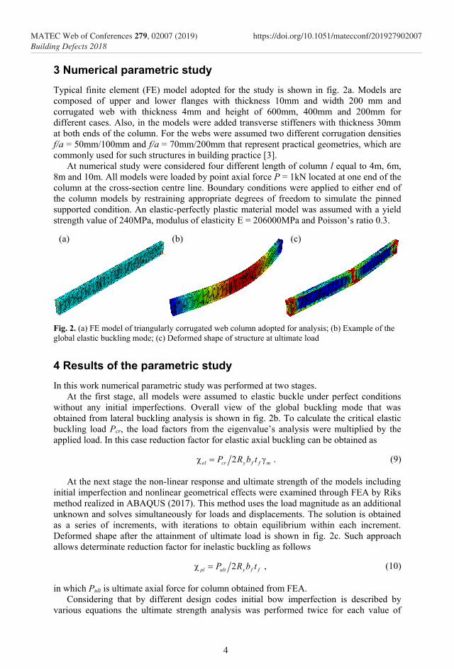
3 Numerical parametric study Typical finite element (FE) model adopted for the study is shown in fig. 2a. Models are composed of upper and lower flanges with thickness 10mm and width 200 mm and corrugated web with thickness 4mm and height of 600mm, 400mm and 200mm for different cases. Also, in the models were added transverse stiffeners with thickness 30mm at both ends of the column. For the webs were assumed two different corrugation densities f/a = 50mm/100mm and f/a = 70mm/200mm that represent practical geometries, which are commonly used for such structures in building practice [3].
At numerical study were considered four different length of column l equal to 4m, 6m, 8m and 10m. All models were loaded by point axial force P = 1kN located at one end of the column at the cross-section centre line. Boundary conditions were applied to either end of the column models by restraining appropriate degrees of freedom to simulate the pinned supported condition. An elastic-perfectly plastic material model was assumed with a yield strength value of 240MPa, modulus of elasticity E = 206000MPa and Poisson’s ratio 0.3.
.
Fig. 2. (a) FE model of triangularly corrugated web column adopted for analysis; (b) Example of the global elastic buckling mode; (c) Deformed shape of structure at ultimate load
4 Results of the parametric study In this work numerical parametric study was performed at two stages.
At the first stage, all models were assumed to elastic buckle under perfect conditions without any initial imperfections. Overall view of the global buckling mode that was obtained from lateral buckling analysis is shown in fig. 2b. To calculate the critical elastic buckling load Pcr, the load factors from the eigenvalue’s analysis were multiplied by the applied load. In this case reduction factor for elastic axial buckling can be obtained as
2el cr y f f mP R b t . (9)
At the next stage the non-linear response and ultimate strength of the models including initial imperfection and nonlinear geometrical effects were examined through FEA by Riks method realized in ABAQUS (2017). This method uses the load magnitude as an additional unknown and solves simultaneously for loads and displacements. The solution is obtained as a series of increments, with iterations to obtain equilibrium within each increment. Deformed shape after the attainment of ultimate load is shown in fig. 2c. Such approach allows determinate reduction factor for inelastic buckling as follows
2pl ult y f fP R b t , (10)
in which Pult is ultimate axial force for column obtained from FEA. Considering that by different design codes initial bow imperfection is described by
various equations the ultimate strength analysis was performed twice for each value of
(a) (b) (c)
4
MATEC Web of Conferences 279, 02007 (2019) https://doi.org/10.1051/matecconf/201927902007Building Defects 2018

imperfections and were got two values of the ultimate force Pult1 and Pult2 for initial imperfection determined by formulas (5) and (8) respectively. FEA results and the values of the reduction factors are given in Table 1 and Table 2 for various corrugation densities.
Table 1. FEA results and reduction factors for columns with corrugation density f/a = 50mm/100mm
Model Pcr , kN χel Pult1 , kN χpl1 χSP Pult2 , kN χpl2 χEN
l=4, hw = 0.2 1672.2 1.340 750.24 0.781
0.767
641.17 0.668
0.693 l=4, hw = 0.4 1668.7 1.337 847.06 0.882 750.10 0.781
l=4, hw = 0.6 1670.2 1.338 836.94 0.872 740.54 0.771
l=6, hw = 0.2 745.53 0.597 592.80 0.618
0.534
433.42 0.451
0.470 l=6, hw = 0.4 744.89 0.597 619.36 0.645 467.78 0.487
l=6, hw = 0.6 745.38 0.597 589.55 0.614 470.34 0.490
l=8, hw = 0.2 420.65 0.337 384.25 0.400
0.341
333.23 0.347
0.314 l=8, hw = 0.4 420.41 0.337 448.23 0.467 354.78 0.370
l=8, hw = 0.6 420.67 0.337 454.54 0.473 360.22 0.375
l=10, hw = 0.2 269.19 0.216 294.30 0.307
0.218
261.71 0.273
0.218 l=10, hw = 0.4 269.08 0.216 338.31 0.352 278.70 0.290
l=10, hw = 0.6 269.23 0.216 351.10 0.366 285.19 0.297
Analyzing the data can be noted that for the relatively slender columns with lengths 8m and 10m the minimum obtained values of reduction factors corresponds to the elastic buckling predicting by Euler’s theory. For the relatively rigid columns with lengths 4m and 6m, the minimum obtained values of reduction factors correspond to the inelastic buckling mode. In other words, columns with corrugated webs behave like an ordinary column with a flat web, but the first one has a greater load capacity due to obtained reduction factors are greater for most cases up to 30% compared with the flat web columns of the same slenderness. As can be seen from the presented data the corrugation density weakly affects the buckling performance of the structure and values of the reduction factors for two types of corrugation looks almost similar. Table 2. FEA results and reduction factors for columns with corrugation density f/a = 70mm/200mm
Model Pcr , kN χel Pult1 , kN χpl1 χSP Pult2 , kN χpl2 χEN l=4, hw = 0.2 1675.4 1.342 755.97 0.787
0.767
646.37 0.673
0.693 l=4, hw = 0.4 1661.6 1.331 862.96 0.899 762.94 0.795
l=4, hw = 0.6 1663.9 1.333 915.18 0.953 881.89 0.919
l=6, hw = 0.2 744.51 0.597 559.56 0.583
0.534
495.97 0.517
0.470 l=6, hw = 0.4 743.71 0.596 522.70 0.544 540.34 0.563
l=6, hw = 0.6 744.3 0.596 577.18 0.601 611.57 0.637
l=8, hw = 0.2 419.12 0.336 415.80 0.433
0.341
387.72 0.404
0.314 l=8, hw = 0.4 418.79 0.336 453.61 0.473 426.87 0.445
l=8, hw = 0.6 419.06 0.336 421.07 0.439 447.11 0.466
l=10, hw = 0.2 268.66 0.215 326.62 0.340
0.218
304.31 0.317
0.218 l=10, hw = 0.4 268.5 0.215 360.60 0.376 340.78 0.355
l=10, hw = 0.6 268.64 0.215 382.10 0.398 353.76 0.369
5
MATEC Web of Conferences 279, 02007 (2019) https://doi.org/10.1051/matecconf/201927902007Building Defects 2018

Generalizing the results, in fig. 3 is given a graph shows the dependence of the values of reduction factors on the non-dimensional slenderness of member.
Fig. 3. Buckling curves for axial compressed column and results of FEA.
5 Conclusions According to the results of the performed work, it is shown that European [8, 9] and Russian [10, 11] design codes are not perfect in evaluation of load carrying capacity for axial compressed members with triangularly corrugated web. So, for practical design procedure, it is recommended to calculate reduction factor for columns with corrugated web according to the existing design codes in the same way like for the flat web columns neglecting the influence of corrugated web on cross sections parameters.
Surely the buckling performance of such structures requires further investigation considering the influence of various boundary conditions, potential eccentricity of the applied load, imperfections in corrugated web and its alignment relative the flanges.
References 1. L. Huang, H. Hikosaka, K. Komine, Comput. Struct. 82, 23-26, 2061–2069 (2004) 2. S. Kudryavtsev, IOP Conf. Ser.: Mater. Sci. and Eng., 365, 042034 (2018) 3. S. V. Kudryavtsev, Calculation and design of welded I-section with corrugated webs,
(Publ. of Ural University, Yekaterinburg, Russia, 2017) 4. S. P. Timoshenko, J. Gere, Theory of elastic stability (1963) 5. C. R. Calladine, Int. J. Mech. Sci., 15, 7, 593–604 (1973) 6. A. Fraser, Experimental investigation of the strength of multiweb beams with
corrugated webs (NACA, Washington, 1956) 7. X. Wang, Behavior of steel members with trapezoidally corrugated webs and tubular
flanges under static loading (Drexel University, USA, 2003) 8. EN 1993-1-1, Eurocode 3: Design of steel structures - Part 1-1: General rules and
rules for buildings (European Committee for Standardization, 2005) 9. EN 1993-1-5, Eurocode 3: Design of steel structures – Part 1-5: Plated structural
elements (European Committee for Standardization, 2006) 10. SP 16.13330.2017, Steel Structures (Ministry of Construction, 2017), in Russian 11. SP 294.1325800.2017, Steel Structures. Design Rules (Ministry of Construction,
Russia, 2017)
According SP 16.13330.2017 [10]
According EN 1993-1-1 [8]
Elastic buckling
6
MATEC Web of Conferences 279, 02007 (2019) https://doi.org/10.1051/matecconf/201927902007Building Defects 2018
Copyright © 2022 FDOKUMEN