
Buckling, symmetry breaking, and cavitation in periodically micro-structured hydrogel membranes
Upload
khangminh22Category
view
0download
0
PART 6 CHAPTER 3
RULES FOR CLASSIFICATION OF
SIDPS
NEWBUILDINGS
SPECIAL EQUIPMENT AND SYSTEMS ADDITIONAL CLASS
PERIODICALLY UNATTENDED MACHINERY SPACE JANUARY 1999
SECTIONS PAGE
1 General Requirements .. . . . . . . . . . . . . . . . . . . . . . . . . . . . . . . . . . . . . . . . . . . . . . . . . . . . . . . . . . . . . . . . . . . . . . . . . . . . . . . . . . . . . . . . 1 2 System Arrangement . . . . . . . . . . . . . . . . . . . . . . . . . . . . . . . . . . . . . . . . . . . . . . . . . . . . . . . . . . . . . . . . . . . . . . . . . . . . . . . . . . . . . . . . . . . 3 3 Class Notation EO . . . . . . . . . . . . . . . . . . . . . . . . . . . . . . . .. . . . . . . . . . . . . . . . . . . . . . . . . . . . . . . . . . . . . . . . . . . . . . . . . . . . . . . . . . . . . . 6 4 Class Notation ECO .......................................................................................... 15 5 Survey ........................................................................................................... 16
DET NORSKE VERITAS Veritasveien 1, N-1322 Hovik, Norway Tel.: +47 67 57 99 00 Fax: +47 67 57 99 11
CHANGES IN THE RULES
General The present edition of the Rules includes additions and amendments decided by the Board in December 1998, and supersedes the July 1995 edition of the same chapter.
The Rule changes come into force on 1st of July 1999.
This chapter is valid until superseded by a revised chapter. Sup-plements will not be issued except for an 'updated list of minor amendments and corrections presented in Pt.O Ch.1 Sec.3. The introduction booklet is normally revised in January and July each year.
Revised chapters will be forwarded to all subscribers to the Rules. Buyers of reprints are advised to check the updated list of Rule chapters printed in Pt.O Ch.1 Sec.1 to ensure that the chapter is current.
Main changes
• Sec.1 General Requirements - In item A200 an addition to paragraph A204 has been added to
document the requirement to keep an approved maintenance and test plan onboard.
- In item ClOO an addition to paragraph C102 has been added to
Comments to the Rules may be sent by e-mail to [email protected].
update the plan for systematic maintenance and function testing. The additions to the plan includes: Columns showing test dates and verification of tests, instrumentation, automation and control systems affecting main functions, test "intervals involving failure of particular systems and the functional testing of critical alarms.
• Sec.2 System arrangement.
- A guidance note has been added to paragraph F103 explaining the use of thermal detectors in workshops adjacent to machinery spaces.
• Sec.3 Class notation EO
- An amendment has been made to the last sentence in paragraph A201 to include "request from the alarm system".
- In item ElOl - "high level alarm" is no longer required in the collecting tank mentioned in the last sentence.
- Table A9 has been amended to include "fuel oil drain collecting tank, level, high".
Corrections and Clarifications In addition to the above stated rule amendments, some detected er-rors have been corrected, and some clarifications have been made in the existing rule wording.
For subscription orders or information about subscription tenns, please use [email protected]. Comprehensive information about DNV and the Society's services is found at the Web site http://www.dnv.com
© Det Norske Veritas AS Computer Typesetting by Division Technology and Products, Det Norske Veritas AS Printed in Norway by Det Norske Veritas AS January 1999
1.99.5500
~u~hyp~~;6~f !u~!=r~r~~;d 0Jir~~~ 1~11s~ ~rh~ca~!g~~o~~!~~ehr~~~e~~~g::;go~ s~~ri ~~p~~;~~~~tn °~~~~~~i~~u0:1 ~:\eNnoir~~sVi~t~~~ t~h~~:J 70°:~~ ~;:~~~: ~~~~~=lio~~m/rg~i~~~o~h~i the maximum compensation shall never exceed USO 2 million. In this provision "Det Norske Veritas" shall mean the Foundation Det Norske Veritas as well as all its subsidiaries. directors. officers, employees, -agents and any other acting on behalf of Det Norske Veritas.
CONTENTS
SEC. 1 GENERAL REQUIREMENTS ...................... 1
A. Classification ...... .... .. .... .. .... .. .... .. .. .. .. .... .... .. .. .. .. .. 1 A 100 Application . . . . . . .. .. . . . . . . . . .. .. . . .. . . . .. 1 A 200 Class notations . . . . . . . . . . . . . . . . . . . . . . . .. . . . . . . . . . . . . . . . . . 1
B. Documentation •.. .•.. ...... ..••.. ...... ..••.. ...•....... ..••.. .. .. 1 B 100 Plans and particulars . . . . . . . . . . . . . . . . . . . . . . 1
C. Operation and maintenance manuals .... ...... ...... ....... 2 C 100 General . . . . . . . . . . . . . . . . . . . . . . . . . . . . . . . . . . . . . . . . . . . . . . . . . . . . . 2
SEC. 2 SYSTEM ARRANGEMENT ......................... 3
A. General .. .. .. .. .. .. .. .. .. .. .. .. .. .. .. .. •. .. .. ...... .... .. . ... .. ..... 3 A 100 Extent of automation . . . . . . . . . . . . . . . . . . . . . . . . . . . . . . . . . . . . . 3
B. Automatic Control System .... ........................ ...... ... 3 B 100 General .. .. .. .. .... .. .... .. .... .. .... .. .... ... .. .. .. .. .. .. . . 3 B 200 Special requirements . . . . . . .. . . . .. . . . . .. . . . . . . . . . . . . . . . . 3
C. Alarm System .... .... ...... ...... ...... ...... ..................... 3 C 100 General .. .. .. .. . . .. .. .. .. ... . .. ... . .. . .. .. ..... .. .... .. .... 3 C 200 Alarm system on the bridge . . . . . . . .. . . . . .. . . . . . . . . . . . . . 3 C 300 Alarm system in the accommodation . . . . . . . . . . . . . . . . . . 3
D. Safety System ..................................................... 3 D 100 General . . . . . . . . . . . . . . . . . . . . . . . . . . . . . . . . . . . . . . . . . . . . . . . . . . . . . 3 D 200 Automatic start of pumps . . . . . .. . . . . .. . . . . .. . . . . .. . . . . . . . 4 D 300 Automatic start/connection of diesel generator units 4 D 400 Automatic stop of auxiliary engines and propulsion
machinery . . . . . . . . . . . . . . . . . . . . . . . . . . . . . . . . . . . . . . . . . . . . . . . . . . 4 D 500 Automatic stop of oil fired auxiliary boilers . . . . . . . . . 4
E. Communication System ......•••............ ..••.. ...... ....... 5 E 100 General . . . . . . . . . . . . . . . . . . . . . . . . . . . . . . . . . . . . . . . . . . . . . . . . . . . . . 5
F. Fire Detection and Alarm System .. ...... ... .. .. .. .. .. .. .. .. • 5 F 100 General .... .... .. .... .. .... ... . .. .. .. .. .... .. ..... .. .... .. .. 5
SEC. 3 CLASS NOTATION EO ............................... 6
A. Extent of Monitoring .. ... .. .. .. .. .. ..... .... .. ...... ... .. .. .... . 6 A 100 General . . . . . . . . . . . . . . . . . . . . . . . . . . . . . . . . . . . . . . . . . . . . . . . . . . . . . 6 A 200 Safety actions . . . . . . . . . . . . . . . . . . . . . . . . . . . . . . . . . . . . . . . . . . . . . . 6
B. Arrangement on the Bridge .... ............................... 6 B 100 General . . . . . . . . . . . . . . . . . . . . . . . . . . . . . . . . . . . . . . . . . . . . . . . . . . . . . 6
C. Arrangement in the Engine Room ...... ...... ...... ...... ... 6 C 100 General ........ .... .. ...... .... .. .... .. .... .. ..... .. .... .. .. 6
D. Electric Power Supply .... ...... ........ ........ ........ ........ 6 D 100 Main source .............. _.:.............. 6 D 200 Secondary distribution system~ . . .. . . . . . . . .. .. .. .. .. . . 7
E. Fire Safety .. .. .... .. .. .... .. .... .. ... .. .. .. .. .. .. .. .... .. ... .. .. .. . 7 E 100 General . . . . . . . . . . . . . . . . . . . . . . . . . . . . . . . . . . . . . . 7
F. Special Requirements for Ships less than 300 Tons Gross with propulsive Output less than 1000 kW per Engine .............................................................. 7
F 100 Extent of monitoring . . . . . . . .. . . . . . . . . . . . . . . . . . . . . . .. . . . . 7 F 200 Arrangement on the bridge . . . . . . . .. . . . . . . . . . . . .. .. . . .. . . 7 F 300 Electric Power Supply . . . . . . . . . . . . . . . . . . . . . . . . . . . . . . . . . . . 7 F 400 Fire safety . . . . . . . . . . . . . . . . . . . . . . . . . . . . . . . . . . . . . . . . . . . . . . . . . . 7 F 500 Fire alarm system. .. . . . . . . . . . . . . . . . . . . . . . . .. .. . . . . . . .. . . . . 7
SEC. 4 CLASS NOTATION ECO ........................... 15
A. General Requirements ...... ........ ...... ........ ............. 15 A 100 Application . . . . . . . . . . . . . . . . . . . . . . . . . . . . . . . . . . . . . . . . . . . . . . 15
B. Control Station ................... ........ ........ ....... ...... .. 15 B 100 Arrangement . .. ... .. . .. . .. ... . .. .. ..... .. .. .. .. .... 15
C. System Arrangement .. ........ .............. ......... ...... .... 15 C 100 General . . . . . . . . . . . . . . . . . . . . . . . . . . . . . . . . . . . . . . . . . . . . . . . . . 15 C 200 Alarm system . . . . . . . . . . . . . . . . . . . . . . . . . . . . . . . . . . . . . . . . . . . . . 15 C 300 Safety system . . . . . . . . . . . . . . . . . . . . . . . . . . . . . . . . . . . . . . . . . . . . 15 C 400 Remote control system .. ...... .. .. .. .. .. .... .. ... . .. ... 15 C 500 Fire alarm system . . . . . . . . . . . . . . . . . . . . . . . . . . . . . . . . . 15
D. Extent of Monitoring ............ ........ ....................... 15 D 100 General . .... .. .... .. ... . .. .. .... .. .. .. .. .. ... . . .. .. .. .. ... . 15
SEC. 5 SURVEY .. ...... ................................... ...... 16
A. General .. ...... .. ... .. .. .. .. .. .. .. .. .. .. .. .. ... .. .. .. .. .. .. .. .. .. .. 16 A 100 Trials .. .... .. .. .... .. .... .. .. .. . ... .. .. .. .. .... ... .. .. .. .. . . 16 A 200 Monitoring system .. . . .. . . .. . . . . .. .. . . .. . . . . .. .. .. . . .. .. . 16 A 300 Automatic control systems . .. ... .. .... .. .. .... ... ... .. . 16 A 400 Electric generating system .. . . . .. . . .. . . . . . . .. ... . .. .. .. . 16 A 500 Fire alarm system ......... .... .. ... ... .. .... .. .... .. ..... 16 A 600 Remote control system . . . . . . . . .. .. . .. . . . . . . ... .. .. . .. . . . 16
B. Testing of Remote Control System. Guidance ........... 16 B 100 Motor ships with fixed pitch propeller . . . . . . . . . . . . . . . 16 B 200 Motor ships with controllable pitch propeller . . . . . . . 17 B 300 Turbine ships . . . . . . . . . . . . . . . . . . . . . . . . . . . . . . . . . . . . . . . . . . . . . 17
C. Testing of Boiler Plant. Guidance .. ......... ...... ......... 17 C 100 Automatic control system for auxiliary boilers . . . . . 17 C 200 Automatic control system for main boilers . . . . . . . . . . 17 C 300 Monitoring system . .. . .. . . . .. .. . . . . . .. . .. . . . .. .. .. . . . .. . . 18

2
Rules for Ships , January 1999 Pt.6 Ch.3 Sec.1 - Page 1
SECTION 1 GENERAL REQUIREMENTS
Contents
A. Classific.ation A I 00 Application A 200 Class notations
B. Documentation B 100 Plans and particulars
C. Operation and maintenance manuals C I 00 General
A. Classification A 100 Application 101 The Rules in this Chapter apply to machinery spaces where arrangements are provided to ensure that the safety of the ship in all sailing conditions, including manoeuvring, as well as alongside quay, is equivalent to that of a ship having machinery spaces attended. Cargo handling is pot included.
A 200 Class notations 201 When all machinery in the engine room necessary for performance of main functions, as specified in Pt.! Ch.! Sec.2, is fitted with instrumentation and automation equip-ment (including computer based system) in compliance with the requirements of Pt.4 Ch.5 and relevant sections of this chapter, Class Notations EO or ECO may be granted. 202 Class Notation EO which is considered to meet the regulations of the International Convention for the Safety of Life at Sea (SOLAS) with latest Amendments as per 1992.01.01 for unattended machinery spaces is granted when machinery alarms are relayed to the bridge and engi-neers' accommodation, and a bridge control system for main propulsion machinery is fitted. 203 Class Notation ECO which is considered to meet the regulations of the International Convention for the Safety of Life at Sea (SOLAS) with latest Amendments as per
1992.01.01 for continuous supervision from a control station is granted when machinery alarms are released in an at-tended centralized control station, and a remote control sys-tem for main propulsion machinery from at least this station is fitted. 204 The assignment of class is based on the assumptions that:
- engineering staff can attend the machinery space at short notice
- systematic maintenance and functional testing of instru-mentation are performed and documented and necessary test equipment is kept on board
- maintenance and testing programs are approved and an original, stamped copy is kept onboard and presented at annual and complete periodical surveys as specified in Pt.7 Ch.2 Sec.4.
Guidance note: When considering to what extent availability of spare parts, re-dundancy or manual operation facilities should be arranged for, due regard should be taken to the manning level in order to ascertain continuity of operation upon failure of the instrumen-tation equipment.
---e-n-d---o-f---G-u-i-d-a-n-c-e---n-o-t-e---
B. Documentation
B 100 Plans and particulars 101 For general requirements for documentation of in-strumentation and automation, including computer based control and monitoring, see Pt.4 Ch.5 Sec.!. 102 For requirements related to fire protection, detection and extinction, see Pt.4 Ch.6 Sec. I.
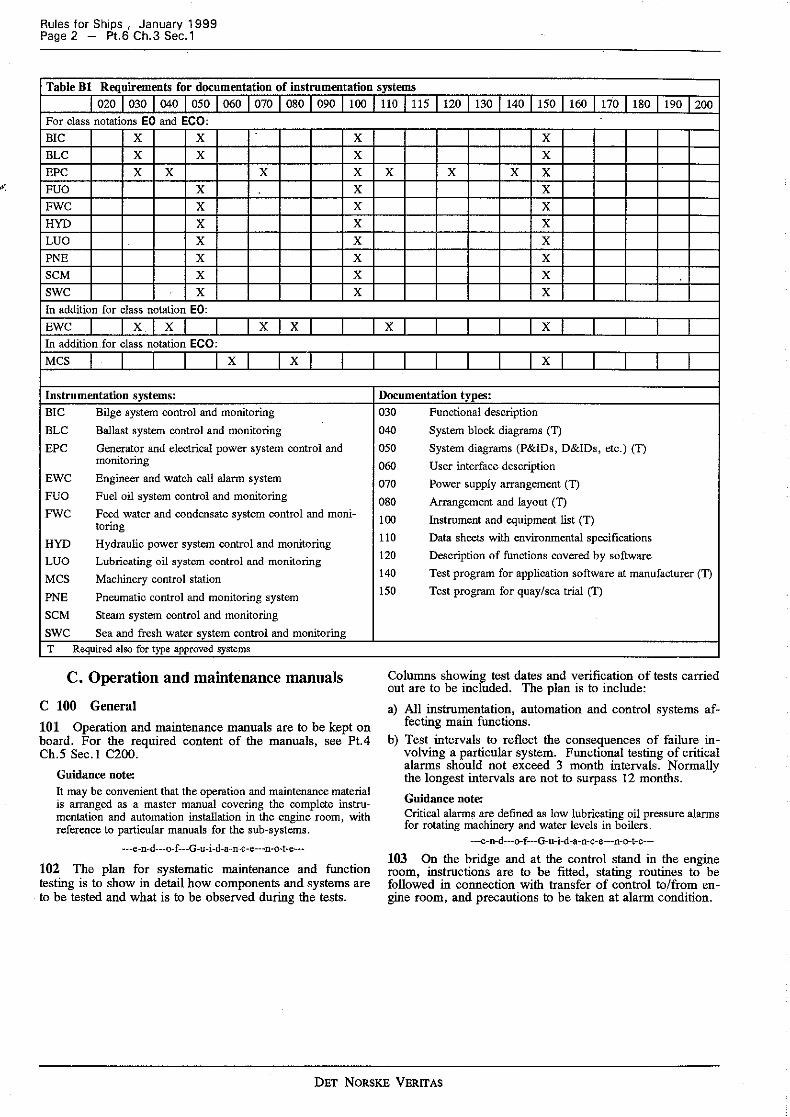
103 For the instrumentation systems listed, documentation is to be submitted according to Table Bl. The upper row of Table B 1 refers to the documentation types defined in Pt.4 Ch.5 Sec.! C200.
DET NORSKE VERITAS
Rules for Ships , January 1999 Page 2 - Pt.6 Ch.3 Sec.1
Table Bl Requirements for documentation of instrumentation systems 020 030 040 050 060 070 080 090 100
For class notations EO and ECO: BIC x x x BLC x x x EPC x x x x FUO x x FWC x x HYD x x LUO x x PNE x x SCM x x swc x x In addition for class notation EO: EWC x x x x In addition .for class notation ECO: MCS x x
Instrumentation systems: BIC Bilge system control and monitoring BLC Ballast system control and monitoring EPC Generator and electrical power system control and
monitoring EWC Engineer and watch call alarm system FUO Fuel oil system control and monitoring FWC Feed water and condensate system control and moni-
to ring HYD Hydraulic power system control and monitoring LUO Lubricating oil system control and monitoring MCS Machinery control station
PNE Pneumatic control and monitoring system SCM Steam system control and monitoring swc Sea and fresh water system control and monitoring T Required also for type approved systems
C. Operation and maintenance manuals
C 100 General
101 Operation and maintenance manuals are to be kept on board. For the required content of the manuals, see Pt.4 Ch.5 Sec.! C200.
Guidance note: It may be convenient that the operation and maintenance material is arranged as a master manual covering the complete instru-mentation and automation installation in the engine room, with reference to particular manuals for the sub-systems.
---e-n-d---o-f---G-u-i-d-a-n-c-e---n-o-t-e--
102 The plan for systematic maintenance and function testing is to show in detail how components and systems are to be tested and what is to be observed during the tests.
110 115 120 130 140 150 160 170 180 190 200
x x
x x x x x x x x x x x
x x
x
Documentation types: 030 Functional description 040 System block diagrams (T)
050 System diagrams (P&!Ds, D&!Ds, etc.) (T) 060 User interface description 070 Power supply arrangement (T)
080 Arrangement and layout (T)
100 Instrument and equipment list (T) 110 Data sheets with environmental specifications 120 Description of functions covered by software 140 Test program for application software at manufacturer ('D
150 Test program for quay/sea trial (T)
Columns showing test dates and verification of tests carried out are to be included. The plan is to include:
a) All instrumentation, automation and control systems af-fecting main functions.
b) Test intervals to reflect the consequences of failure in-volving a particular system. Functional testing of critical alarms should not exceed 3 month intervals. Normally the longest intervals are not to surpass 12 months. Guidance note: Critical alarms are defined as low lubricating oil pressure alarms for rotating machinery and water levels in boilers.
--e-n-d---o-f---G-u-i-d-a-n-c-e---n-o-t-e---
103 On the bridge and at the control stand in the engine room, instructions are to be fitted, stating routines to be followed in connection with transfer of control to/from en-gine room, and precautions to be taken at alarm condition.
DET NORSKE VERITAS
Rules for Ships , January 1999 Pt.6 Ch.3 Sec.2 - Page 3
SECTION 2 SYSTEM ARRANGEMENT
Contents
A. General A 100 Extent of automation
B. Automatic Control System B 100 General B 200 Special requirements
C. Alarm System C 100 General C 200 Alarm system on the bridge C 300 Alarm system in the accommodation
D. Safety System D 100 General D 200 Automatic start of pumps D 300 Automatic start/connection of diesel generator units D 400 Automatic stop of auxiliary engines and propulsion ma-
chinery D 500 Automatic stop of oil fired auxiliary boilers
E. Communication System E 100 General
F. Fire Detection and Alarm System F 100 General
A. General A 100 Extent of automation 101 The extent of automation is to be sufficient to permit unattended engine room operation for 24 hours, or for the maximum continuous operation time when less than 24 hours. Normal service at sea and normal manoeuvres is presumed. Normal manoeuvres do not include emergency manoeuvres, where alarm and safety limits may be ex-ceeded. 102 Starting of engine plant and transfer to various oper-ating modes may be accepted as manual operations, if the need for such actions will not arise at short notice.
B. Automatic Control System B 100 General 101 Automatic control systems are to keep all parameters within the limits for safe operation under all load conditions.
B 200 Special requirements 201 Where the bilge pumps are arranged for automatic starting, alarm is to be released if the influx of liquid is greater than the pump capacity or when the pump is operat-ing more frequently than would normally be expected. 202 For reversible engines, the starting air receivers are to be automatically pumped up.
C. Alarm System C 100 General 101 The alarm system is to be continuously powered and is to have an automatic changeover to a stand-by power supply in case ofloss of normal power supply. The capacity
of the stand-by power supply is to be sufficient for at least 30 minutes operation.
102 The alarm system is to activate the engineers' alarm (repeat alarm) required by Pt.4 Ch. I Sec.3A if a machinery alarm is not acknowledged locally within a limited time.
C 200 Alarm system on the bridge
201 Any alarm condition in the engine room is io release alarm on the bridge with individual or groupwise indication. The visual alarm signal is to remain until acknowledged in the e~gine room.
202 Alarm conditions within one group is not to prevent alarms in other groups. New alarms within a group are not to be blocked by acknowledged existing alarms.
203 The alarm systems on the bridge and in the accom-modation are to be so designed that the more frequent faults, such as power failure or broken connections to the engine room, release alarm.
Guidance note: Separate cable-connections for visual and acoustic signals may be accepted as alternative to live current self monitoring.
---e-n-d---o-f--G-u-i-d-a-n-c-e---n-o-t-e--
204 Alarm is to be released at power failure on the main switchboard.
Guidance note: It is advised that group alarms on the bridge are blocked when the engine room is atten"ded. However, when the main engine is controlled from the bridge, monitoring of the remote control system as well as failure conditions leading to or requesting stop or reduction of main engine, should not be blocked. Acknowledgement of audible signals on the bridge should be possible from the bridge. The light intensity of alarm indicators on the bridge should not be reducible below the intensity neces-sary in normal daylight.
-e-n-d---o-f-G-u-i-d-a-n-c-e--n-o-t-e---
C 300 Alarm system in the accommodation
301 Any alarm condition in the engine room is to release alarm in the watch-keeping engine officer's cabin and day room. Acknowledgement in the cabin is to be indicated on the bridge when the engine room is unattended.
D. Safety System
D 100 General
101 The safety system is to cover fault conditions which may develop too fast to be counteracted by manual inter-vention locally.
102 When two or more safety actions are released by one failure condition (e.g. start of standby pump and stop of engine at low lubricating oil pressure), these actions are to be activated at different levels. The least drastic action is to be activated first.
DET NORSKE VERITAS
Rules for Ships , January 1999 Page 4 - P1.6 Ch.3 Sec.2
103 Power failure in the safety system is not to cause loss of propulsion or steering functions.
104 Whenever the safety system is activated, alarm is to be released.
D 200 Automatic start of pumps 201 Faults in the mechanical or electrical system of the running pump are not to inhibit automatic start_ of the standby pump.
202 Automatic start of the standby pump is to be initiated by the process parameter which is being monitored, e.g. low pressure signal, and is to be arranged so that the standby pump does not stop automatically when first started (•locking circuit»).
203 Manual start and stop of the pumps are to be possible without release of alarm for automatic start of the standby pump.
204 Operating circuits for pump units are to be arranged according to Pt.4 Ch.4.
205 When a pump is standby, this is to be clearly indicated on the switch panel by indicating lamps, etc.
D 300 Automatic start/connection of diesel generator units 301 When several generator units have individual systems for automatic start and connection on to the main switch-board, each system is to be selectively fused (separate short circuit protection), and alarm is to be released for voltage failure.
302 Automatic attempts which fail to produce a start are to be limited to restrict consumption of starting energy.
303 Tachometer feedback to the starting system is to be arranged so that broken mechanical pinions or external electrical connections do not lead to stop of a running gen-erator unit. Neither are such faults to inhibit automatic stop or alarm functions.
304 Manual start and stop of generator uoits are not to release alarm.
305 The generator circuit breaker is to be provided with automatic wind up of the closing spring of the breaker.
306 Simultaneous connection of generators on to the main switchboard is not to be possible.
307 If there is no arrangement for automatic synchroniza-tion, parallelling and load sharing, connection is only to be possible when auxiliary contacts on the generator circuit breakers show directly that all generators are disconnected from the main switchboard.
308 When a generator unit is standby, this is to be indi-cated on the control panel.
309 The voltage of a generator being connected on to a de-energised switchboard is to be sufficiently high for safe operation of all connected circuits.
310 No more than one attempt of automatic connection on to a de-energised switchboard is permitted.
311 Systems with automatic synchronization, connection, and load sharing are to be designed so that deviations in voltage, frequency, and phase at the instant of connection are within adequate safety limits for generator and engine.
312 Means for manual synchronization and parallelling are to be provided.
313 When automatic start of standby generator unit is caused by reduction of voltage or frequency below the cri-teria for automatic connection, the running uoit is to be stopped when the standby unit is ready for connection.
314 Systems with automatic start of the standby unit at heavy load on running units are to be arranged with ade-quate delay to prevent false start attempts, e.g. caused by short load peaks.
315 The battery supplying the diesel engine automatic start/stop system is to have at least twice the capacity re-quired for maximum load for 112 hour for all consumers connected to the system.
316 Batteries are generally to be continually charged (trickle charge) from a charge rectifier having sufficient ca-pacity to supply the sum of the trickle charge current, the current according to the fuse rating of the largest consumer, and the normal load current for all other consumers. A lower charge rectifier capacity may be approved, pro-vided the distribution system is monitored for ground faults. The capacity is not to be less than the sum of the trickle charge current plus average normal load during 24 hours for all consumers with a 10% allowance in addition.
D 400 Automatic stop of auxiliary engines and propulsion machinery 401 The system for automatic stop and alarm is to be se-lectively fused (separate short circuit protection). Similarly, automatic stop circuits for individual units are to be selec-tively fused. Alarm is to be released for voltage failure.
402 The safety system is to be arranged so that a single open circuit in wiring between sensors and control unit, or between control unit and actuators, does not cause uninten-tional stop.
Guidance note: A single system based on normally open contacts can be ac-cepted; alternatively, a system with normally closed contacts where discrimination between broken connections and stop sig-nals is provided.
---e-n-d---o-f---G-u-i-d-a-n-c-e---n-o-t-e---
403 The requirements of 402 can be waived if the ma-noeuvrability is maintained after shutdown of one unit, see Pt.4 Ch.5 Sec.3A.
404 All parameters which may cause automatic stop are normally to release alarm prior to stop.
Guidance note: Propulsion machinery is defined as all machinery which will cause loss of the propulSion function if stopped, with exception of main boilers.
---e-n-d---o-f--G-u-i-d-a-n-c-e---n-o-t-e---
D 500 Automatic stop of oil fll"ed auxiliary boilers 501 Connections between sensors and control unit are to be based upon normally closed contacts, so that an open circuit will lead to shutoff of the oil supply.
DET NORSKE VERITAS

502 The parameter causing an automatic stop is to be identified on the control panel.
E. Communication System
E 100 General
101 A communication system is to be installed, making it possible at any time (also during blackout) to call the engine officers from the bridge and from the engine room. Two-way voice communication is required for ships over 2000 tons gross.
102 For sbips above 2000 tons gross, at least 4 simul-taneous voice connections are to be possible, alternatively the connection between the bridge and the engine rooms is to have priority above other connections.
Rules for Ships , January 1999 Pt.6 Ch.3 Sec.2 - Page 5
F. Fire Detection and Alarm System F 100 General 101 An automatic fire detection and fire alarm system in accordance with the requirements of Pt.4 Ch. 6 is to be fitted in the machinery spaces. ·· 102 The fire detection system is to be so designed and the detector so located that all potential fire outbreak points are effectively guarded at all normal conditions of machinery operation and variations of ventilation. 103. A combination of detectors is normally required in order to enable the system to react to various fire charac-teristics. Except in spaces of restricted height and where their use is especially appropriate, detection systems using .only thermal detectors are not accepted. Fire detectors are to be type approved.
Guidance note: Thermal detectors only may be used in workshops adjacent to machinery spaces when the nature of the work being carried out will cause erroneous alarms. This guidance note only applies if the compartments themselves do not contain fuel oil installations.
---e-n-d---o-f---G-u-i-d-a-n-c-e---n-o- t-e---
104 Manually operated call points are to be located at the following positions:
- passageways/stairways having nearby entrance to engine and boiler rooms
- navigation bridge - control station m engine room.
DET NORSKE VERITAS
Rules for Ships , January 1999 Page 6 - Pt.6 Ch.3 Sec.3
SECTION 3 CLASS NOTATION EO
A. Extent of Monitoring A 100 General A 200 Safety actions
Contents 205 When both an alarm and an automatic safety action are required for one failure condition, alarm is to be acti-vated first.
B. Arrangement on the Bridge B. Arrangement on the Bridge B 100 General
C. Arrangement in the Engine Room C 100 General
D. Eloctric Power Supply D 100 Main source D 200 Secondary distribution systems
E. Fire Safety E 100 General
F. Special Requirements for Ships less than 300 Tons Gross with propulsive Output less than 1000 kW per Engine
F 100 Extent of monitoring F 200 Arrangement on the bridge F 300 Electric Power Supply F 400 Fire safety F 500 Fire alarm system.
A. Extent of Monitoring
A 100 General 101 The monitoring system is to cover machinery and equipment having functions necessary for the safety and manoeuvrability of the ship, see Pt. I Ch. I Sec.2 A200.
102 The parameters to be monitored will depend upon output and type of engine as well as arrangement of ma-chinery plant. Normally, it will be required that the param-eters listed in Tables Al to A9 are monitored. Other combinations than those listed may be accepted, when the chosen monitoring can detect fault conditions in an equiv-alent satisfactory manner. For monitoring of gas turbine installations, see Pt.4 Cb.2 Sec.4 E400.
A 200 Safety actions 201 Unless otherwise specified, the safety shut-downs and slow-downs required in the tables may be executed auto-matically or manually from the bridge upon such request from the alarm system.
202 When emerging device for overriding a safety action is provided, it is to be such arranged that unintentional op-eration is prevented, and it should be clearly indicated when the device is operated.
203 Normally an emergency device would be required on the bridge for overriding of automatic shutdowns which are installed additional to those specified in the Tables Al to AS.
204 For multi-engine plants, overriding of safety shut-downs is not required if manoeuvrability of the vessel is maintained.
B 100 General 101 All alarms in the engine room are to release alarm on the bridge, individual or collective.
102 Individual alarm is required for:
- automatic shutdown of main boiler - automatic shutdown and/or slowdown of propulsion ma-
chinery - request for manual shutdown and/or slowdown of pro-
pulsion machinery - power failure bridge alarm system - power failure bridge control system.
C. Arrangement in the Engine Room
C 100 General 101 Indicating instruments, alarm displays and manoeuvr-ing devices are to be centralized in a convenient position, in or adjacent to the engine room.
Guidance note: The layout of instruments in the control desk should comply with generally accepted ergonomic principles. Red lamps should be used only as alarm lamps.
---e-n-d---o-f---G-u-i-d-a-n-c-e---n-o-t-e---
D. Electric Power Supply
D 100 Main source 101 Arrangements are to be provided to prevent over-loading of generating sets.
102 The main source of electrical power is to comply with the following:
- Where the electrical power can normally be supplied by one generator adequate provision shall be made, on loss of power, for automatic starting and connecting to the main switchboard of the stand-by generator with auto-matic restarting of the essential auxiliaries. Connection to the main switchboard to be completed within 30 seconds after loss of power.
- Where the electrical power is normally supplied by more than one generator simultaneously in parallel operation, provision shall be made to ensure that, in case of loss of one of these generating sets, the remaining ones are kept in operation to permit propulsion and steering.
103 Standby generating sets are normally to have separate cooling water and lubricating oil pumps. Alternatively, au-tomatic start of standby pumps is to be arranged when they also serve other generating sets.
DET NORSKE VERITAS
104 When the manoeuvrability of the ship is independent of electric power, the requirements of 102 do not apply.
D 200 Secondary distribution systems 201 For essential consumers with power supply from sec-ondary distribution systems, precautions against power fail-ure are to be similar to those taken for units having power supply from the main system. E.g., the following means may be applied:
- adequate automatic emergency lighting for access to standby transformer for the lighting system and operating gear for manual connection
- automatic connection of standby transformer - parallel connection of a sufficient number of transformers
and arrangement for' selective disconnection - automatic connection of emergency source of power - dividing the system in two or more circuits with automatic
switchover.
In this context, essential consumers are units and equipment necessary for manoeuvring of the ship, including navigation lights and sufficient lighting (either as part of the normal lighting or as separate emergency lighting) in the engine room, on the bridge, in the chart room, in all passageways and stairways of the accommodation.
E. Fire Safety
E 100 General 101 Where the Society finds it necessary, oil fuel and lu-bricating oil pressure pipelines are to be screened or other-wise suitably protected to avoid as far as practicable oil spray or leakages on to hot surfaces or into machinery air intakes. Fuel oil injection pipes on all engines, irrespective of cylinder bore, are to be effectively shielded and secured. The number of joints in such piping systems are to be kept to a minimum and, where practicable, leakages from high pressure oil fuel pipes are to be collected and safe drainage to a collecting tank is to be provided.
Rules for Ships , January 1999 Pt.6 Ch.3 Sec.3 - Page 7
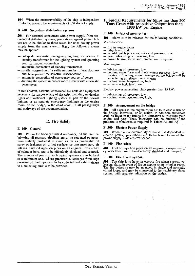
F. Special Requirements for Ships less than 300 Tons Gross with propulsive Output less than
1000 kW per Engine F 100 Extent of monitoring · 101 Alarm is to be released for tlie following conditions: Miscellaneous: - fire in engine room - bilge level, high - vanable pitch propeller, servo oil pressure, low - gear, lubricating oil pressure, low - power failure, alarm and remote control system. Main engine: - lubricating oil pressure, low · - cooling water (sea- and fresh water) pressure, low. In-
dication of cooling water pressure on the bridge will be accepted as an alternative to alarms
- cooling water temperature, high - expansion tank level, low. Electric power generating plant greater than 35 kW: - lubricating oil pressure, low - cooling water temperature, high.
F 200 Arrangement on the bridge 201 All alarms in the engine room are to release alarm on the bridge, individual or collective. In addition, indicators shall be fitted on the bridge for lubrication oil pressure main engine and gear. These indicators can be omitted if the pressure is monitored as required in Tables Al and AS.
F 300 Electric Power Supply 301 When the manoeuvrability of the ship is dependent on electric power, precautions are to be taken to avoid that power supply units are overloaded.
F 400 Fire safety 401 Fuel oil injection pipes on all engines, irrespective of cylinder bore, are to be effectively shielded and clamped.
F 500 Fire alarm system. 501 The ship is to have an electric fire alarm system, re-leas~g alarm m event of fire in engine room or boiler room. The f"rre detectors may be arrangeil in single and normally closed loops, and may be connected to the machinery alarm system, with separate indication on the bridge.
DET NORSKE VERITAS
Rules for Ships , January 1999 Page 8 - Pt.6 Ch.3 Sec.3
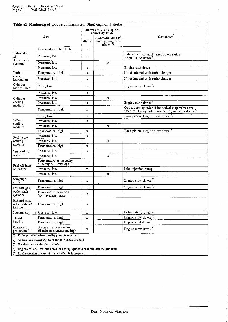
Table Al Monitoring of propulsion machinery. Diesel engines. 2-stroke Alann and safety action
(stated by an x) Item Automatic start of
Alarm standby pumfi with alarm )
Temperature inlet, high x Lubricating
Pressure, low oil. x All separate systems Pressure, low x
Pressure, low x Turbo- Temperature, high x charger
Pressure, low lubrication x
Cylinder lubrication 2) Flow, low x
Pressure, low x
Cylinder Pressure, low x cooling Pressure, low x medium
Temperature, high x
Flow, low x Piston Pressure, low x cooling
Pressure, low medium x Temperature, high x
Fuel valve Pressure, low x cooling Pressure, low x medium Temperature, high x
Sea cooling Pressure, low x water Pressure, low x
Temperature or viscosity x Fuel oil inlet of heavy oil, low/high on engine Pressure, low x
Pressure, low x Scavenge air 3) Temperature, high x
Exhaust gas, Temperature, high x outlet each Temperature deviation cylinder from average, large x
Exhaust gas, outlet exhaust Temperature, high x turbine Starting air Pressure, low x
Thrust Temperature, high x bearing Temperature, high x Crankcase Bearing temperature or protection 4) oil mist concentration, high x
I) To be provided when standby pump is required 2) At least one measuring point for each lubricator unit 3) For detection of fire (per cylinder) 4) Engines of 2250 kW and above or having cylinders of more than 300mm bore. 5) Load reduction in ca·se of controllable pitch propeller,
Comments -
Independent of safets) shut down system. Engine slow down
Engine shut down If not integral with turbo charger
If not integral with turbo charger
Engine slow down 5)
Engine slow down ') Outlet each cylinder if individual stop valves are fitted for the cylinder jackets. Engine slow down S) Each piston. Engine slow down ) )
Each piston. Engine slow down ;, )
Inlet injection pump
Engine slow down 5)
Engine slow down 5)
Before starting valve Engine slow down ) ) Engine shut down
Engine slow down 5)
DEf NORSKE VERITAS
Rules for Ships , January 1999 Pt.6 Ch.3 Sec.3 - Page 9
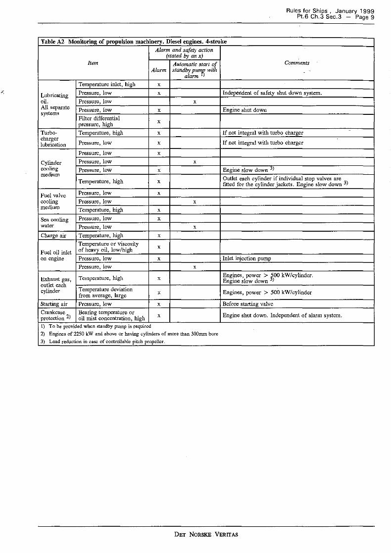
Table A2 Monitoring of propulsion machinery. Diesel engines. 4-stroke Alarm and safety action
(stated by an x) Item Automatic start of Comments
Alarm standby pumfi with -alarm )
Temperature inlet, high x
Lubricating Pressure, low x Independent of safety shut down system. oil. Pressure, low x All separate Pressure, low x Engine shut down systems
Filter differential pressure, high x
Turbo- Temperature, high x If not integral with turbo charger ..
charger Pressure, low lubrication x If not integral with turbo charger
Pressure, low x Cylinder Pressure, low x cooling Pressure, low x Engine slow down j) medium
Outlet each cylinder if individual stop valves are Temperature, high x fitted for the cylinder jackets. Engine slow down 3)
Fuel valve Pressure, low x
cooling Pressure, low x medium Temperature, high x
Sea cooling Pressure, low x water Pressure, low x Charge air Temperature, high x
Temperature or viscosity x
Fuel oil inlet of heavy oil, low/high on engine Pressure, low x Inlet injection pump
Pressure, low x
Exhaust gas, Te1nperature, high x Engines, power > 500 kW/cylinder. Engine slow down 3)
outlet each Temperature deviation cylinder from average, large x Engines, power > 500 kW/cylinder
Starting air Pressure, low x Before starting valve Crankcase Bearing temperature or Engine shut down. Independent of alarm system. protection 2) oil mist concentration, high x
!) To be provided when standby pump is required 2) Engines of 2250 kW and above or having cylinders of more than 300mm bore 3) Load reduction in case of controllable pitch propeller.
DET NORSKE VERITAS
Rules for Ships , January 1999 Page 10 - Pt.6 Ch.3 Sec.3
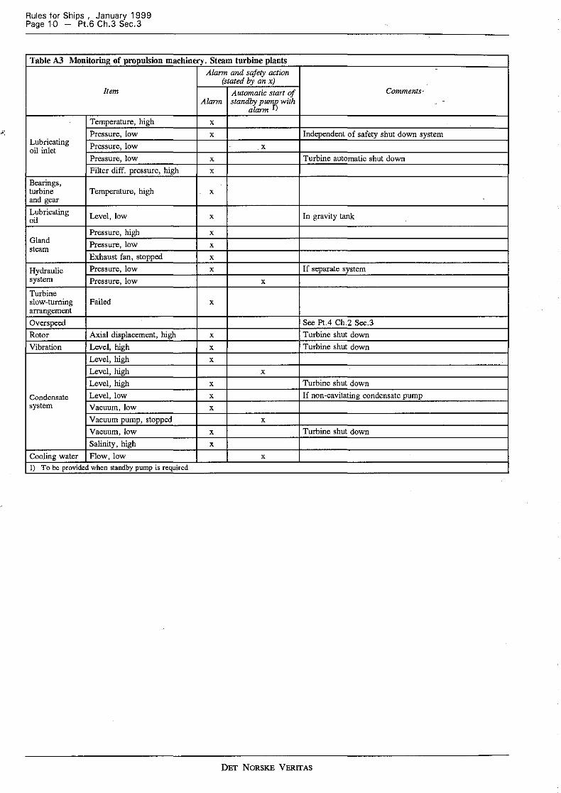
Table A3 Monitoring of propulsion machinery. Steam turbine plants Alarm and safety action
(stated by an x) Item Automatic start of Comments·
Alann standby pumfi with -alarm )
Temperature, high x
Pressure, low x Independent of safety shut down system Lubricating Pressure, low x oil inlet
Pressure, low x Turbine automatic shut down Filter diff. pressure, high x
Bearings, turbine Temperature, high x and gear Lubricating Level, low x In gravity tank oil
Pressure, high x Gland Pressure, low steam x
Exhaust fan, stopped x
Hydraulic Pressure, low x If separate system system Pressure, low x
Turbine slow-turning Failed x arrangement
Overs peed See Pt.4 Ch.2 Sec.3 Rotor Axial displacement, high x Turbine shut down Vibration Level, high x Turbine shut down
Level, high x
Level, high x
Level, high x Turbine shut down
Condensate Level, low x If non-cavitating condensate pump system Vacuum, low x
Vacuum pump, stopped x
Vacuum, low x Turbine shut down Salinity, high x
Cooling water Flow, low x
1) To be provided when standby pump is required
DET NORSKE VERITAS
Rules for Ships , January 1999 Pt.6 Ch.3 Sec.3 - Page 11
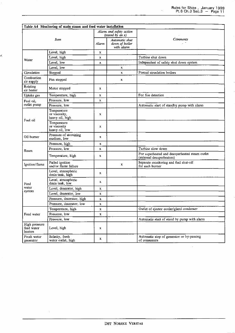
Table A4 Monitoring of main steam and feed water installation Alann and safety action
(stated by an x) Item Automatic shut Comments
Alann down of boiler -
with alarm
Level, high x
Level, high x Turbine shut down Water
Level, low x Independent of safety shut down system Level, low x
Circulation Stopped x Forced circulation boilers Combustion Fan stopped x air supply Rotating Motor stopped x air heater Uptake gas Temperature, high x For fire detection
Fuel oil, Pressure, low x outlet pump Pressure, low Automatic start of standby pump with alarm
Temperature or viscosity, x
Fuel oil heavy oil, high Temperature or viscosity x heavy oil, low
Oil burner Pressure of atomizing x medium, low Pressure, high x
Steam Pressure, low x Turbine slow down
Temperature, high x For superheated and desuperheated steam outlet (external desuperheaters)
Ignition/flame Failed ignition x Separate monitoring and fuel shut-off and/ or flame failure for each burner Level, atmospheric x drain tank, high Level, atmospheric x Feed drain tank, low
water Level, deaerator, high x system
Level, deaerator, low x
Pressure, deaerator, high x
Pressure, de.aerator, low x
Temperature, high x Outlet of ejector cooler/gland condenser Feed water Pressure, low x
Pressure, low Automatic start of stand by pump with alarm High pressure feed water Level, high x heaters Fresh water Salinity, fresh Automatic stop of generator or by-passing generator water outlet, high x of consumers
DET NORSKE VERITAS
Rules for Ships , January 1999 Page 12 - Pt.6 Ch.3 Sec.3
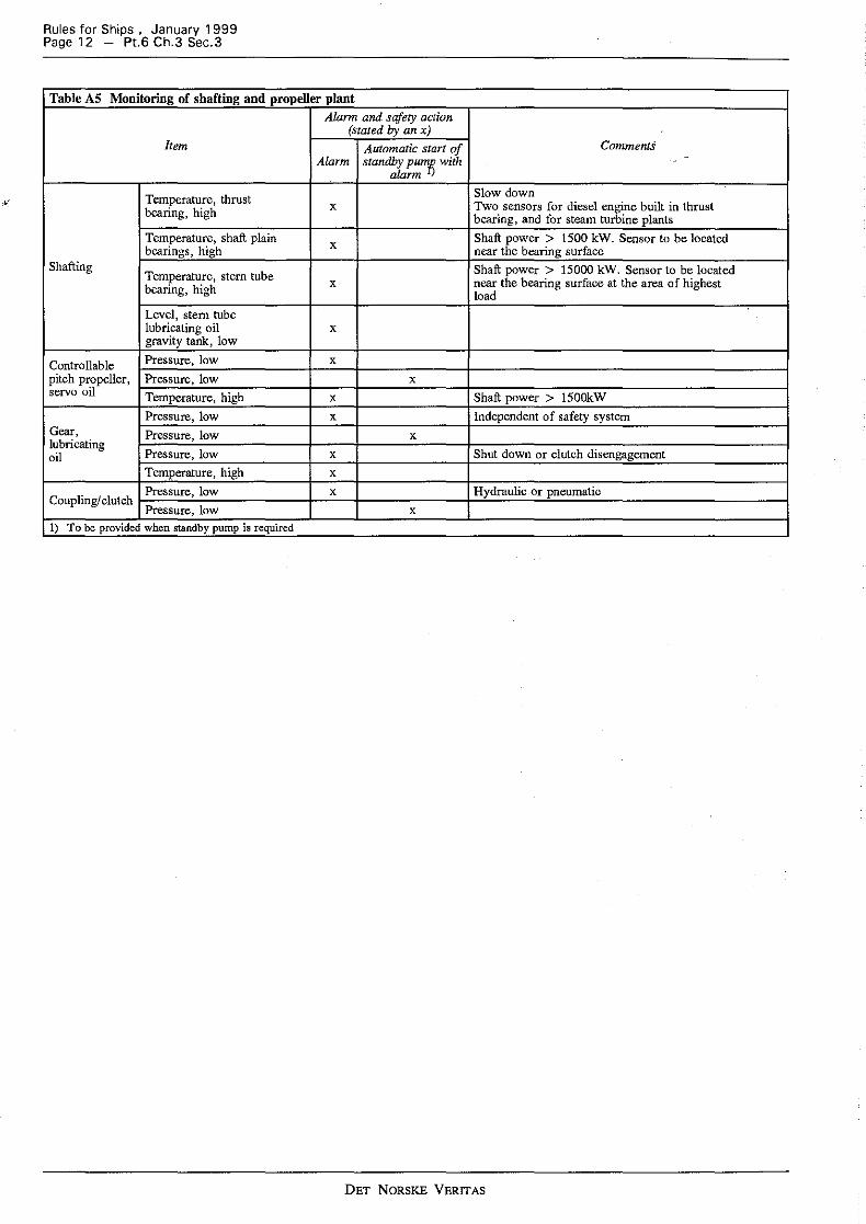
Table AS Monitoring of shafting and propeller plant Alarm and safety action
(stated by an x) Item Automatic start of Comments
Alarm standby pum{i with -
alarm )
Temperature, thrust Slow down x Two sensors for diesel engine built in thrust bearing, high bearing, and for steam turbine plants
Temperature, shaft plain x Shaft power > 1500 kW. Sensor to be located bearings, high near the bearing surface
Shafting Temperature, stem tube Shaft power > 15000 kW. Sensor to be located
x near the bearing surface at the area of highest bearing, high load Level, stem tube lubricating oil x gravity tank, low
Controllable Pressure, low x pitch propeller, Pressure, low x servo oil Temperature, high x Shaft power > 1500kW
Pressure, low x Independent of safety system Gear, Pressure, low x lubricating
Pressure, low Shut down or clutch disengagement oil x Temperature, high x Pressure, low x Hydraulic or pneumatic
Coupling/clutch Pressure, low x
1) To be provided when standby pump is required
DET NORSKE VERITAS
Rules for Ships , January 1999 Pt.6 Ch.3 Sec.3 - Page 13
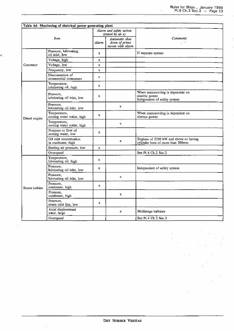
Table A6 Monitoring of electrical power generating plant Alarm and safery action
(stated by an x) Item Automatic shut Comments
Alann down of prime -mover with alarm
Pressure, lubricating x If separate system oil inlet, low Voltage, high x
Generator Voltage, low x Frequency, low x Disconnection of nonessential consumers x
Temperature, x lubricating oil, high
Pressure, When manoeuvring is dependent on lubricating oil inlet, low x electric power.
Independent of safety system Pressure, x lubricating oil inlet, low Temperature, x When manoeuvring is dependent on
Diesel engine cooling water outlet, high electric power Temperature, x cooling water outlet, high Pressure or flow of cooling water, low x
Oil mist concentration x Engines of 2250 kW and above or having in crankcase, high cylinder bore of more than 300mm Starting air pressure, low x Overs peed See Pt.4 Ch.2 Sec.2 Temperature, x lubricating oil, high Pressure, x Independent of safety system lubricating oil inlet, low Pressure, x lubricating oil inlet, low Pressure, x
Steam turbine condenser, high Pressure, x condenser, high Pressure, x steam inlet line, low Axial displacement x Multistage turbines rotor, large Overspeed See Pt.4 Ch.2 Sec.3
DET NORSKE VERITAS
Rules for Ships , January 1999 Page 14 - Pt.6 Ch.3 Sec.3
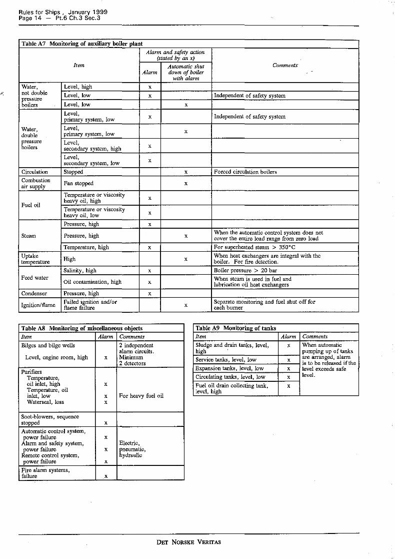
Table A 7 Monitoring of auxiliary boiler plant Alann and safety action
(stated by an x) Item Automatic shut Comments
Alarm down of boiler -
with alarm
Water, Level, high x not double Level, low x Independent of safety system pressure boilers Level, low x
Level, x Independent of safety system primary system, low
Water, Level, x double primary system, low pressure Level, boilers secondary system, high x
Level, x secondary system, low Circulation Stopped x Forced circulation boilers Combustion air supply Fan stopped x
Temperatur~ or viscosity x Fuel oil
heavy oil, high Temperature or viscosity x heavy oil, low Pressure, high x
Steam Pressure, high x When the automatic control system does not cover the entire load range from zero load
Temperature, high x For superheated steam > 350°C Uptake High x When heat exchangers are integral with the temperature boiler. For fire detection.
Salioity, high x Boiler pressure > 20 bar Feed water
Oil contamination, high When steam is used in fuel and x lubrication oil heat exchangers Condenser Pressure, high x
Ignition/flame Failed ignition and/or x Separate monitoring and fuel shut off for flame failure each burner
Table A8 Monitoring of miscellaneous objects Table A9 Monitoring of tanks Item Alarm Comments Item Alarm Comments
Bilges and bilge wells 2 independent Sludge and drain tanks, level, x When automatic alarm circt.iits. high pumping up of tanks
Level, engine room, high x Minimum 2 detectors Service tanks, level, low x are arranged, alarm
is to be released if the Purifiers
Temperature,
Expansion tanks, level, low x level exceeds safe Circulating tanks, level, low x level.
oil inlet, high x Temperature, oil inlet, low x For heavy fuel oil
Fuel oil drain collecting tank, x level, high
Waterseal, loss x
Soot-blowers, sequence stopped x Automatic control system, power failure x
Alarm and safety system, Electric, power failure x pneumatic,
Remote control system, hydraulic powel". failure x
Fire alarm systems, failure x
DET NORSKE VERITAS
Rules for Ships , January 1999 Pt.6 Ch.3 Sec.4 - Page 15
SECTION 4 CLASS NOTATION ECO
A. General Requirements A 100 Application
B. Control Station B 100 Arrangement
C. System Arrangement C 100 General C 200 Alarm system C 300 Safety system
Contents
C 400 Remote control system C 500 Fire alarm system
D. Extent of Monitoring D 100 General
A. General Requirements
A 100 Application 101 This section applies to machinery operation with con-tinuous supervision from a centralized control station. The control station is to provide control and monitoring devices necessary to make the machinery operation as safe and ef-fective as it would be under direct supervision.
B. Control Station
B 100 Arrangement 101 The arrangement is to be such that all superv1s10ns and manual operations which are necessary for safe opera-tion of the machinery plant can be carried out at the control station. This will imply that stopping of machinery, starting of stand-by units etc. in case of machinery faults is to be possible from the control station if not automatically carried out.
102 The control station is to be located in the engine room or in its close proximity.
C. System Arrangement C i 00 General 101 The requirements of Section 2 are to be complied with to the extent applicable.
C 200 Alarm system 201 A system of alarm displays are to be provided in the centralized control station for easy identification of machin-ery faults. 202 The machinery alarms need not be relayed to the bridge and engineers accommodation.
C 300 Safety system 301 The safety systems specified m Sect10n ZD can be omitted. Corrective actions at machinery faults are pre-sumed to be carried out manually.
C 400 Remote control system 401 Propulsion machinery is to be arranged for remote control from the centralized control station. The require-ments given in Pt.4 Ch.2 Sec.! are to be complied with to the ex tent applicable.
C 500 Fire alarm system 501 The fire alarm system is to satisfy the requirement of Section ZF.
D. Extent of Monitoring D 100 General 101 The alarms required according to Section 3 are to be provided. The automatic safety actions required in the same section such as stop of engine, start of stand-by pumps, and start of stand-by generator can be omitted, and carried out manually.
DET NoRsKE VERITAS
Rules for Ships , January 1999 Page 16 - Pt.6 Ch.3 Sec.5
SECTION 5 SURVEY
Contents
A. General A 100 Trials A 200 Monitoring system A 300 Automatic control systems A 400 Electric generating system A 500 Fire alarm system A 600 Remote control system
B. Testing of Remote Control System. Guidance B 100 Motor ships with fixed pitch propeller B 200 Motor ships with controllable pitch propeller B 300 Turbine ships
C. Testing of Boiler Plant. Guidance C 100 Automatic control system for auxiliary boilers C 200 Automatic control system for main boilers C 300 Monitoring system
A. General A 100 Trials 101 Upon completion of the installation, trials are to be carried out alongside quay and at sea in the presence of the surveyor. 102 The sea trials should be reserved solely for testing of the automatic and the remote control systems, and the frre alarm system. Other tests should be completed alongside quay. 103 The sea trials are to include a four hours continuous operation with unattended machinery spaces.
Agreement is to be made in advance in each case for per-sonnel that will be present in the control room.
Guidance note: Personnel for ordinary upkeep and control of the machinery are not to be present in the engine room. Special measurements can be carried out according to agreement, e.g. noise measurements.
---e-n-d---o-f---G-u-i-d-a-n-c-e---n-o-t-e---
104 A detailed test programme is to be prepared and sub-mitted for approval well in advance of the trials. The pro-gramme is to be kept onboard, all filled in and signed by the surveyor upon completion of the trials. 105 Recording of important automatically controlled pa-rameters may be required as part of the testing.
A 200 Monitoring system 201 Failure conditions are to be simulated as realistically as possible, preferably by letting the monitored parameters exceed the alarm and safety limits. The alarm and safety limits are to be recorded in the test programme.
202 Any calibration of sensors prior to installation onboard is to be approved by the surveyor.
A 300 Automatic control systems 301 Automatic control systems are to be tested by varying the parameters having effect upon the controlled process. As far as practicable it is to be verified that all normal con-trol ranges are covered.
Guidance note: Observation of the automatic control system performance during
the tests specified under B for the remote control system will normally be accepted as adequate testing.
---e-n-d---o-f---G-u-i-d-a-n-c-e--n-o-t-e---
A 400 Electric generating system
401 At bridge control and half speed ahead, simulate a fault condition causing automatic stop of electric power generator.
402 For plants with automatic start and connection of stand-by unit, check restart of all essential auxiliaries, and that the bridge control system is again operative without manual intervention in the engine room.
403 For plants with more than one generator running in parallel, it is to be checked that the stopped unit is automat-ically disconnected from the switchboard, and that the gen-erator capacity of the remaining units is sufficient for propulsion and steering functions after tripping of non-es-sential consumers.
A 500 Fire alarm system
501 It is to be verified that the fire detectors are such lo-cated that air current will not make the system inoperative.
A 600 Remote control system
601 Testing of the remote control system for the propul-sion machinery is to be carried out at sea. Prior to testing, the propulsion machinery is to run for at least 1 hour. 602 All tests included in the test programme for the remote control system are to be carried out without manual assist-ance from the engine room, and all systems are to be in operation as normal for unattended machinery space.
B. Testing of Remote Control System. Guidance
B 100 Motor ships with frxed pitch propeller 101 The test programme should as a minimum include the following manoeuvres:
- from stop to dead slow ahead. Proceed stepwise to full ahead. Before each step increase, the r.p.m. of the pre-vious setting is to have reached its steady state condition
- from approximately 2/3 of full speed ahead, go quickly to slow astern. Proceed stepwise to full astern
- stop - after approximately 5 minutes stop, start ahead - when the ship has reached approximately 2/3 of full
speed ahead, go quickly to half astern - when the ship is •dead in the water», go quickly to full
ahead - when the ship has reached approximately 2/3 of full
speed ahead, go quickly to dead slow ahead - when the r.p.m. is nearly stabilized, go quickly to full
ahead - when the ship has reached approximately half speed
ahead, go to stop and back to dead slow ahead within 1 second.
102 With air compressors stopped, make 12 starts with the remote control system, alternatively between ahead and ast-ern.
DET NORSKE VERITAS
103 Testing of possible automatic restarts. Go to ahead and let the engine repeat the predetermined starting at tempts. Go to stop. Return to ahead and check that an addi-tional starting attempt is effected. 104 Simulate failures causing automatic load reduction or stop of the engine. Cancel if possible this safety action and show that the engine is again controllable from the bridge. 105 During bridge control at half speed ahead, cut out power supply to the remote control system. No immediate critical situation is to arise. Switch over to standby manual control in the engine room, and show that this control sys-tem functions satisfactorily. 106 At approximately 2/3 of full speed ahead, test the emergency stop system.
B 200 Motor ships with controllable pitch propeller 201 The tests specified below apply to remote control systems with a single manoeuvring lever on the bridge. For plants with dual lever control, one for r.p.m. and one for pitch, the tests to be carried out will be considered in each case.
- start the engine, from the bridge if possible, and go to dead slow ahead. Proceed stepwise to full ahead. Before each step increase, the r.p.m. of the previous setting is to have reached its steady state condition
- from approximately 2/3 of full speed ahead, go quickly to dead slow astern. Proceed stepwise to full astern
- go to neutral position - after approximately 5 minutes in neutral position, go to
ahead - when the ship has reached approximately 2/3 of full
speed ahead, go quickly to 2/3 of full astern - when the ship is •dead in the water», go quickly to half
ahead.
202 Simulate failures causing automatic load reduction or stop of the engine. Cancel if possible this safety action and show that the engine is again controllable from the bridge. 203 During bridge control at half speed ahead, cut out power supply to the remote control system. No immediate critical situation is to arise. Switch over to standby manual control in the engine room, and show that this control sys-tem functions satisfactorily. 204 At approximately 2/3 of full speed ahead, test the emergency stop system.
B 300 Turbine ships 301 The test programme should as a minimum include:
- from stop to dead slow ahead. Proceed stepwise to full ahead. Before each step increase, the r.p.m. of the pre-vious setting is to have reached its steady state condition
- from full speed ahead, reduce stepwise to stop with the same intervals
- from stop, increase stepwise to full astern. Run until the ship has reached a fair speed astern
- from full astern, reduce stepwise to stop - show that the automatic turning arrangement operates
satisfactorily during the stop period. Go to full ahead - after approximately 10 minutes full ahead, go quickly to
stop - after approximately 5 minutes stop, go quickly to 2/3 of
full astern - when the ship is •dead in the water>, go quickly to full
ahead - when the ship has reached approximately 2/3 of full
speed ahead, go quickly to 2/3 of full astern and run until the ship is •dead in the water>
Rules for Ships , January 1999 Pt.6 Ch.3 Sec.5 - Page 17
- go to full ahead. When the ship has reached approxi-mately 2/3 of full speed ahead, go to stop and back to dead slow ahead within 1 second. Transfer control to the engine room.
302 Repeat the first four manoeuvres using the ma-noeuvring system in the engine room. Transfer control to the bridge. 303 During bridge control at half speed ahead, cut out power supply to the remote control system. No immediate critical situation is to arise. Switch over to standby manual control in the engine room, and show that this control sys-tem functions satisfactorily. 304 Simulate failures causing automatic load reduction or stop of turbines. Cancel, if possible, this safety action and show that the turbines are again controllable from the bridge. 305 At approximately 2/3 of full speed ahead, test the emergency stop system.
C. Testing of Boiler Plant. Guidance C 100 Automatic control system for auxiliary boilers 101 The system is to be tested by varying the boiler load as specified in 102. Recording of the following parameters may be required:
- steam pressure (primary and secondary system) - water level in boiler - automatic actions such as start and/or stop of burners,
alarms, etc.
102 Boilers serving turbogenerators. One boiler in opera-tion:
- increase load from minimum to full load during a period of minimum 15 minutes
- reduce load from full load to minimum during a period of minimum 15 minutes
- increase load suddenly to minimum 50 % of full load by connecting one of the greater consumers
- when stationary conditions are reached, reduce load sud-denly to minimum.
Parallel operation of two boilers:
- increase load suddenly to minimum 30 % of full load, by connecting one of the greater consumers
- when stationary conditions are reached, reduce load sud-denly to approximately 5 % of full load and keep that load until stationary conditions are reached.
C 200 Automatic control system for main boilers 201 The system is to be tested by varying the boiler load as specified in 202. Recording of the following parameters may be required:
- steam flow (alternatively position of control valve) - steam pressure - temperature of superheated steam - water level in boiler - water level in condenser and deaerator - fuel oil temperature or viscosity - excess of combustion air in exhaust gas.
202 The boiler load is to be varied in accordance with the manoeuvring tests specified in B 300. The boiler plant test-ing may be carried out simultaneously with testing of the remote control system for the main turbines.
DET NORSKE VERITAS
Rules for Ships , January 1999 Page 18 - Pt.6 Ch.3 Set.5
C 300 Monitoring system 301 With all burners in operation, the fuel oil supply to one of the burners is to be shut off. Check that the flame detector of this burner is functioning. The remaining burners are to be tested in the same way. 302 With burners in operation, one of the flame detectors is to be shielded. Check that the automatic shutoff valve for fuel oil is operating. The remaining flame detectors are to be tested in the same way.
303 With boiler in operation, simulate a failure causing automatic stop of combustion air fan. Check that the fuel oil supply is shut off.
304 Reduce water level below safety limit and check that fuel oil supply is shut off. -
305 Remaining alarms and safety actions are to be released by simulating failures as realistically as practicable.
DET NORSKE VERITAS
Copyright © 2022 FDOKUMEN