Input Interface Format - DNV
376
SESAM INTERFACE FORMAT DESCRIPTION Input Interface Format Finite Element Model and Loads Data Types Valid from SIF version 10
-
Upload
khangminh22 -
Category
Documents
-
view
3 -
download
0
Transcript of Input Interface Format - DNV

SESAM INTERFACE FORMAT DESCRIPTION
Input Interface Format
Finite Element Model and Loads Data Types
Valid from SIF version 10

Sesam Interface Format Description
SIF
Date: 2022-01-06
Valid from SIF version 10
Prepared by: Digital Solutions at DNV
E-mail support: [email protected]
E-mail sales: [email protected]
©DNV AS. All rights reserved
This publication or parts thereof may not be reproduced or transmitted in any form or by any means, including copying
or recording, without the prior written consent of DNV AS.
|Sesam Interface Format Description|SIF 10|

Table of contents
1 INTRODUCTION . . . . . . . . . . . . . . . . . . . . . . . . . . . . . . . . . . . . . . . . . . . . . 11.1 Purpose . . . . . . . . . . . . . . . . . . . . . . . . . . . . . . . . . . . . . . . . . . . . . . . . 11.2 How to Read the Manual . . . . . . . . . . . . . . . . . . . . . . . . . . . . . . . . . . . . . . . 12 IDENTIFICATION DATA FOR SUPER ELEMENTS AND TEXT DATA . . . . . . . . . . . . . . . . . . . 22.1 Identification Data . . . . . . . . . . . . . . . . . . . . . . . . . . . . . . . . . . . . . . . . . . 22.1.1 DATE: Date and Program Information . . . . . . . . . . . . . . . . . . . . . . . . . . . . . . 32.1.2 IDENT: Identification of a Super Element . . . . . . . . . . . . . . . . . . . . . . . . . . . . 42.1.3 IEND: End of a Super Element . . . . . . . . . . . . . . . . . . . . . . . . . . . . . . . . . . 52.1.4 UNITS: Definition of the consistent units used in this Sesam Interface file . . . . . . . . . . 62.2 Text Data . . . . . . . . . . . . . . . . . . . . . . . . . . . . . . . . . . . . . . . . . . . . . . . 82.2.1 TDELEM: Name of an Element and/or comment . . . . . . . . . . . . . . . . . . . . . . . . 92.2.2 TDLOAD: Name of a Local Load Case and/or comment . . . . . . . . . . . . . . . . . . . . 102.2.3 TDMATER: Name of a Material Type and/or comment . . . . . . . . . . . . . . . . . . . . . 112.2.4 TDNODE: Name of a Node and/or comment . . . . . . . . . . . . . . . . . . . . . . . . . . 122.2.5 TDSECT: Name of a General Eccentric Sandwich Section and/or comment . . . . . . . . . 132.2.6 TDSETNAM: Name of a Set and/or comment . . . . . . . . . . . . . . . . . . . . . . . . . . 142.2.7 TDSUPNAM: Name of a Super Element and/or comment . . . . . . . . . . . . . . . . . . . 152.2.8 TEXT: User supplied Text . . . . . . . . . . . . . . . . . . . . . . . . . . . . . . . . . . . . . 172.2.9 TSLAYER: Name of a General Eccentric Sandwich Type and/or comment . . . . . . . . . . 183 ELEMENT TYPES . . . . . . . . . . . . . . . . . . . . . . . . . . . . . . . . . . . . . . . . . . . . . 193.1 BEPS: Beam Element for Plane Systems . . . . . . . . . . . . . . . . . . . . . . . . . . . . . . 213.2 CSTA: Plane Constant Strain Triangle . . . . . . . . . . . . . . . . . . . . . . . . . . . . . . . 233.3 ILST: Plane Linear Strain Triangle . . . . . . . . . . . . . . . . . . . . . . . . . . . . . . . . . 253.4 IQQE: Plane Isoparametric Quadrilateral Membrane Element . . . . . . . . . . . . . . . . . . 273.5 LQUA: Plane Incompatible Linear Quadrilateral Membrane Element . . . . . . . . . . . . . . 293.6 TESS: Truss Element . . . . . . . . . . . . . . . . . . . . . . . . . . . . . . . . . . . . . . . . . 313.7 GMAS: 1-Noded Mass Element . . . . . . . . . . . . . . . . . . . . . . . . . . . . . . . . . . . 323.8 GLMA: General 2-Noded Mass Element . . . . . . . . . . . . . . . . . . . . . . . . . . . . . . 333.9 GLDA: General 2-Noded Damping Element . . . . . . . . . . . . . . . . . . . . . . . . . . . . 343.10 BEAS: Beam Element . . . . . . . . . . . . . . . . . . . . . . . . . . . . . . . . . . . . . . . . 353.11 AXIS: Axial Spring . . . . . . . . . . . . . . . . . . . . . . . . . . . . . . . . . . . . . . . . . . 373.12 AXDA: Axial Damper . . . . . . . . . . . . . . . . . . . . . . . . . . . . . . . . . . . . . . . . . 383.13 GSPR: Ground Spring . . . . . . . . . . . . . . . . . . . . . . . . . . . . . . . . . . . . . . . . 393.14 GDAM: Damper to Ground . . . . . . . . . . . . . . . . . . . . . . . . . . . . . . . . . . . . . 403.15 IHEX: Iso-parametric Hexahedron . . . . . . . . . . . . . . . . . . . . . . . . . . . . . . . . . 413.16 LHEX: Linear Hexahedron . . . . . . . . . . . . . . . . . . . . . . . . . . . . . . . . . . . . . . 463.17 SECB: Sub-parametric Curved Beam . . . . . . . . . . . . . . . . . . . . . . . . . . . . . . . . 503.18 BTSS: Sub-parametric General Curved Beam . . . . . . . . . . . . . . . . . . . . . . . . . . . 533.19 FQUS: Flat Quadrilateral Thin Shell . . . . . . . . . . . . . . . . . . . . . . . . . . . . . . . . 553.20 FTRS: Flat Triangular Thin Shell . . . . . . . . . . . . . . . . . . . . . . . . . . . . . . . . . . 583.21 SCTS: Sub-parametric Curved Triangular Shell . . . . . . . . . . . . . . . . . . . . . . . . . . 613.22 MCTS: Sub-parametric Multi-layered Curved Triangular Shell . . . . . . . . . . . . . . . . . . 643.23 SCQS: Sub-parametric Curved Quadrilateral Shell . . . . . . . . . . . . . . . . . . . . . . . . 673.24 MCQS: Sub-parametric Multilayered Curved Quadrilateral Shell . . . . . . . . . . . . . . . . 703.25 IPRI: Iso-parametric Prism . . . . . . . . . . . . . . . . . . . . . . . . . . . . . . . . . . . . . 733.26 ITET: Iso-parametric Tetrahedron . . . . . . . . . . . . . . . . . . . . . . . . . . . . . . . . . . 773.27 TPRI: Triangular Prism . . . . . . . . . . . . . . . . . . . . . . . . . . . . . . . . . . . . . . . . 813.28 TETR: Tetrahedron . . . . . . . . . . . . . . . . . . . . . . . . . . . . . . . . . . . . . . . . . . 843.29 LCTS: Sub-parametric Layered Curved Triangular Shell . . . . . . . . . . . . . . . . . . . . . 873.30 LCQS: Sub-parametric Layered Curved Quadrilateral Shell . . . . . . . . . . . . . . . . . . . 923.31 TRSI: Transition Elements between Solids and Shells . . . . . . . . . . . . . . . . . . . . . . 973.32 GLSH: General 2-Noded Spring / Shim Element . . . . . . . . . . . . . . . . . . . . . . . . . . 1063.33 AXCS: Axi-symmetric Constant Strain Triangle . . . . . . . . . . . . . . . . . . . . . . . . . . 107
|Sesam Interface Format Description|SIF 10| Page i

3.34 AXLQ: Axi-symmetric Constant Strain Quadrilateral . . . . . . . . . . . . . . . . . . . . . . . 1093.35 AXLS: Axi-symmetric Linear Strain Triangle . . . . . . . . . . . . . . . . . . . . . . . . . . . . 1113.36 AXQQ: Axi-symmetric Linear Strain Quadrilateral . . . . . . . . . . . . . . . . . . . . . . . . 1133.37 CTCP: 2-Noded (1+1) Contact Element . . . . . . . . . . . . . . . . . . . . . . . . . . . . . . 1153.38 CTCL: 4-Noded (2+2) Contact Element . . . . . . . . . . . . . . . . . . . . . . . . . . . . . . 1173.39 CTAL: 4-Noded (2+2) Axi-symmetric Contact Element . . . . . . . . . . . . . . . . . . . . . . 1193.40 CTCC: 6-Noded (3+3) Contact Element . . . . . . . . . . . . . . . . . . . . . . . . . . . . . . 1213.41 CTAQ: 6-Noded (3+3) Axi-symmetric Contact Element . . . . . . . . . . . . . . . . . . . . . . 1233.42 CTLQ: 8-Noded (4+4) Contact Element . . . . . . . . . . . . . . . . . . . . . . . . . . . . . . 1253.43 CTCQ: 16-Noded (8+8) Contact Element . . . . . . . . . . . . . . . . . . . . . . . . . . . . . 1273.44 CTMQ: 18-Noded (9+9) Contact Element . . . . . . . . . . . . . . . . . . . . . . . . . . . . . 1293.45 FTAS: Flat Triangular Thin Shell – Drilling degree of freedom . . . . . . . . . . . . . . . . . . 1313.46 FQAS: Flat Quadrilateral Thin Shell – Drilling degree of freedom . . . . . . . . . . . . . . . . 1353.47 HCQS: Heterosis Curved Quadrilateral Shell . . . . . . . . . . . . . . . . . . . . . . . . . . . . 1393.48 THTS: Flat 3-noded Thick Triangular Shell . . . . . . . . . . . . . . . . . . . . . . . . . . . . . 1423.48.1 Element Type 63 . . . . . . . . . . . . . . . . . . . . . . . . . . . . . . . . . . . . . . . . . 1423.48.2 Data types used . . . . . . . . . . . . . . . . . . . . . . . . . . . . . . . . . . . . . . . . . . 1433.48.3 Restrictions . . . . . . . . . . . . . . . . . . . . . . . . . . . . . . . . . . . . . . . . . . . . . 1433.49 THQS: Flat 4-noded Thick Quadrilateral Shell . . . . . . . . . . . . . . . . . . . . . . . . . . . 1453.49.1 Element Type 64 . . . . . . . . . . . . . . . . . . . . . . . . . . . . . . . . . . . . . . . . . 1453.49.2 Data types used . . . . . . . . . . . . . . . . . . . . . . . . . . . . . . . . . . . . . . . . . . 1463.49.3 Restrictions . . . . . . . . . . . . . . . . . . . . . . . . . . . . . . . . . . . . . . . . . . . . . 1463.50 MATR: General Matrix Element . . . . . . . . . . . . . . . . . . . . . . . . . . . . . . . . . . . 1483.51 GHEX: General Hexahedron . . . . . . . . . . . . . . . . . . . . . . . . . . . . . . . . . . . . . 1524 STRUCTURAL CONCEPTS AND CONCEPT ATTRIBUTES . . . . . . . . . . . . . . . . . . . . . . . . 1584.1 The structure concept model . . . . . . . . . . . . . . . . . . . . . . . . . . . . . . . . . . . . 1584.2 Structure concept descriptions . . . . . . . . . . . . . . . . . . . . . . . . . . . . . . . . . . . 1594.2.1 SCONCEPT: Structure concept definition . . . . . . . . . . . . . . . . . . . . . . . . . . . . 1604.2.2 SCONMESH: Structure concept finite element representation . . . . . . . . . . . . . . . . 1624.2.3 SCONPLIS: Structure concept property list . . . . . . . . . . . . . . . . . . . . . . . . . . . 1634.2.4 SPROCODE: Structure concept code checking attributes . . . . . . . . . . . . . . . . . . . 1644.2.5 SPROECCE: Structure concept eccentricity attributes . . . . . . . . . . . . . . . . . . . . . 1664.2.6 SPROHYDR: Structure concept hydrodynamic attributes . . . . . . . . . . . . . . . . . . . 1674.2.7 SPROMATR: Structure concept material attributes . . . . . . . . . . . . . . . . . . . . . . 1694.2.8 SPROORIE: Structure concept orientation attributes . . . . . . . . . . . . . . . . . . . . . . 1704.2.9 SPROPILE: Structure concept pile attributes . . . . . . . . . . . . . . . . . . . . . . . . . . 1714.2.10 SPROSECT: Structure concept cross section attributes . . . . . . . . . . . . . . . . . . . . 1724.2.11 SPROSEGM: Structure concept segment attributes . . . . . . . . . . . . . . . . . . . . . . 1734.2.12 SPROSELE: Structure concept property selectors . . . . . . . . . . . . . . . . . . . . . . . 1744.2.13 SPROSOIL: Structure concept soil data . . . . . . . . . . . . . . . . . . . . . . . . . . . . . 1754.2.14 TDSCONC: Structure concept referable text . . . . . . . . . . . . . . . . . . . . . . . . . . 1804.2.15 Example . . . . . . . . . . . . . . . . . . . . . . . . . . . . . . . . . . . . . . . . . . . . . . . 1815 FIRST LEVEL DATA . . . . . . . . . . . . . . . . . . . . . . . . . . . . . . . . . . . . . . . . . . . 1845.1 Additional Element Data . . . . . . . . . . . . . . . . . . . . . . . . . . . . . . . . . . . . . . . 1845.1.1 ACFD: General Crack Data . . . . . . . . . . . . . . . . . . . . . . . . . . . . . . . . . . . . 1855.1.2 ADDATA: Additional User defined Basic Element Data . . . . . . . . . . . . . . . . . . . . . 1885.2 Boundary Conditions, Loads and Point Masses . . . . . . . . . . . . . . . . . . . . . . . . . . 1895.2.1 BAHAMAS: Element with Added Mass . . . . . . . . . . . . . . . . . . . . . . . . . . . . . . 1915.2.2 BEDRAG1: Hydrodynamic Drag and Damping from Wave Load Program . . . . . . . . . . 1925.2.3 BEISTE: Element with Initial Strain Due to Thermal Expansion . . . . . . . . . . . . . . . . 1935.2.4 BELFIX: Flexible Joint/Hinge . . . . . . . . . . . . . . . . . . . . . . . . . . . . . . . . . . . 1955.2.5 BELLAX: Surface Load on Axi-symmetric Solid . . . . . . . . . . . . . . . . . . . . . . . . . 1965.2.6 BELLO2: Elements with Line Load, Solid, 3D-Shell, 2D-Shell, Membrane and Curved Beam
Elements . . . . . . . . . . . . . . . . . . . . . . . . . . . . . . . . . . . . . . . . . . . . . . 201
|Sesam Interface Format Description|SIF 10| Page ii

5.2.7 BELOAD1: Beam with Line Load . . . . . . . . . . . . . . . . . . . . . . . . . . . . . . . . . 2035.2.8 BEMASS1: Hydrodynamic added Mass from Wave Load Program . . . . . . . . . . . . . . . 2065.2.9 BEUSLO: Element with Surface Load . . . . . . . . . . . . . . . . . . . . . . . . . . . . . . . 2075.2.10 BEUVLO: Elements with Volume Force, 3-D Solid, 2-D Shell and Membrane Elements . . . 2095.2.11 BEWAKIN: Wave Kinematics . . . . . . . . . . . . . . . . . . . . . . . . . . . . . . . . . . . 2115.2.12 BEWALO1: Element Loads from Wave Load Program . . . . . . . . . . . . . . . . . . . . . 2125.2.13 BGRAV: Gravitational Load (Constant of Gravity) . . . . . . . . . . . . . . . . . . . . . . . . 2135.2.14 BLDEP: Node with Linear Dependency . . . . . . . . . . . . . . . . . . . . . . . . . . . . . . 2145.2.15 BNACCLO: Node with Acceleration Load . . . . . . . . . . . . . . . . . . . . . . . . . . . . . 2155.2.16 BNBCD: Node with Boundary Condition . . . . . . . . . . . . . . . . . . . . . . . . . . . . . 2175.2.17 BNDISPL: Node with Displacement, Velocity and/or Acceleration . . . . . . . . . . . . . . . 2185.2.18 BNDOF: Node with Transformation . . . . . . . . . . . . . . . . . . . . . . . . . . . . . . . . 2205.2.19 BNIEQ: Nodes with Non-Linear Contact Dependence . . . . . . . . . . . . . . . . . . . . . . 2215.2.20 BNINCO: Node with Initial Condition If Arbitrary Time Dependent Loading . . . . . . . . . . 2235.2.21 BNLOAD: Node with Load . . . . . . . . . . . . . . . . . . . . . . . . . . . . . . . . . . . . . 2245.2.22 BNLOAX: Node with Load (Line Load) for Axi-symmetric Solid (proposal) . . . . . . . . . . 2255.2.23 BNMASS: Node with Point Mass . . . . . . . . . . . . . . . . . . . . . . . . . . . . . . . . . 2275.2.24 BNTEMP: Node with Temperature and Derivative for Temperature . . . . . . . . . . . . . . 2285.2.25 BNTRCOS: Transformation from Global to Local Co-ordinate System, Direction Cosines . . 2305.2.26 BNWALO: Node Load from Wave Load Program . . . . . . . . . . . . . . . . . . . . . . . . 2315.2.27 BQDP: Node with Simple Quadratic Dependence . . . . . . . . . . . . . . . . . . . . . . . . 2325.2.28 BRIGAC: Rigid Body Acceleration . . . . . . . . . . . . . . . . . . . . . . . . . . . . . . . . 2355.2.29 BRIGDI: Rigid Body Displacement . . . . . . . . . . . . . . . . . . . . . . . . . . . . . . . . 2365.2.30 BRIGVE: Rigid Body Velocity . . . . . . . . . . . . . . . . . . . . . . . . . . . . . . . . . . . 2375.3 Nodal Data and Element Geometry Definition . . . . . . . . . . . . . . . . . . . . . . . . . . . 2385.3.1 GBARM: Cross Section Type Massive Bar . . . . . . . . . . . . . . . . . . . . . . . . . . . . 2405.3.2 GBEAMG: General Beam Element Data . . . . . . . . . . . . . . . . . . . . . . . . . . . . . 2415.3.3 GBOX: Cross Section Type Box Beam . . . . . . . . . . . . . . . . . . . . . . . . . . . . . . 2425.3.4 GCHAN: Cross Section Type Channel Beam . . . . . . . . . . . . . . . . . . . . . . . . . . . 2435.3.5 GCHANR: Cross Section Type Channel Beam with Inside Curvature . . . . . . . . . . . . . 2445.3.6 GCOORD: Nodal Co-ordinates . . . . . . . . . . . . . . . . . . . . . . . . . . . . . . . . . . 2465.3.7 GCROINT: Specification of Integration Points . . . . . . . . . . . . . . . . . . . . . . . . . . 2475.3.8 GDOBO: Section Type Double Bottom . . . . . . . . . . . . . . . . . . . . . . . . . . . . . . 2495.3.9 GECC: Local Eccentricities . . . . . . . . . . . . . . . . . . . . . . . . . . . . . . . . . . . . . 2505.3.10 GECCEN: Eccentricities . . . . . . . . . . . . . . . . . . . . . . . . . . . . . . . . . . . . . . 2515.3.11 GELINT: Specification of Integration Stations . . . . . . . . . . . . . . . . . . . . . . . . . . 2525.3.12 GELMNT1: Element Data Definition . . . . . . . . . . . . . . . . . . . . . . . . . . . . . . . 2555.3.13 GELREF1: Reference to Element Data . . . . . . . . . . . . . . . . . . . . . . . . . . . . . . 2575.3.14 GELSTRP: Specification of Stress Points . . . . . . . . . . . . . . . . . . . . . . . . . . . . . 2605.3.15 GELTH: Thickness of Two-dimensional Elements . . . . . . . . . . . . . . . . . . . . . . . . 2615.3.16 GIORH: Cross Section Type I or H Beam . . . . . . . . . . . . . . . . . . . . . . . . . . . . . 2625.3.17 GIORHR: Cross Section Type I or H Beam with Inside Curvature . . . . . . . . . . . . . . . 2635.3.18 GLMASS: Modification of Diagonal Mass Matrices . . . . . . . . . . . . . . . . . . . . . . . 2645.3.19 GLSEC: Cross Section Type L-Section . . . . . . . . . . . . . . . . . . . . . . . . . . . . . . 2655.3.20 GLSECR: Cross Section Type L-Section with Inside Curvature . . . . . . . . . . . . . . . . . 2665.3.21 GNODE: Correspondence between External and Internal Node Numbering, and Number of
Degrees of Freedom at Each Node . . . . . . . . . . . . . . . . . . . . . . . . . . . . . . . . 2675.3.22 GPGBOX: Cross Section Type Boxed Plate Girder . . . . . . . . . . . . . . . . . . . . . . . . 2685.3.23 GPGDOW: Cross Section Type Boxed Plate Girder . . . . . . . . . . . . . . . . . . . . . . . 2705.3.24 GPIPE: Cross Section Type Tube . . . . . . . . . . . . . . . . . . . . . . . . . . . . . . . . . 2735.3.25 GSEPSPEC: Specified Separation Description . . . . . . . . . . . . . . . . . . . . . . . . . . 2745.3.26 GSETMEMB: Set (group) of Nodes or Elements (Members) . . . . . . . . . . . . . . . . . . 2755.3.27 GSLAYER: General Eccentric Sandwich Element . . . . . . . . . . . . . . . . . . . . . . . . 2775.3.28 GSLPLATE: Plate Layer Description . . . . . . . . . . . . . . . . . . . . . . . . . . . . . . . 278
|Sesam Interface Format Description|SIF 10| Page iii

5.3.29 GSLSTIFF: Stiffener Layer Description . . . . . . . . . . . . . . . . . . . . . . . . . . . . . . 2795.3.30 GTONP: Cross Section T on Plate . . . . . . . . . . . . . . . . . . . . . . . . . . . . . . . . . 2805.3.31 GUNIVEC: Specification of Local Element . . . . . . . . . . . . . . . . . . . . . . . . . . . . 2815.3.32 GUSYI: Cross Section Type Unsymmetrical I-Beam . . . . . . . . . . . . . . . . . . . . . . . 2825.4 Material Data . . . . . . . . . . . . . . . . . . . . . . . . . . . . . . . . . . . . . . . . . . . . . 2845.4.1 MAXDMP: Axial Damper between Two Nodal Points . . . . . . . . . . . . . . . . . . . . . . 2855.4.2 MAXSPR: Axial Spring between Two Nodal Points . . . . . . . . . . . . . . . . . . . . . . . 2865.4.3 MCNT: Material for Non-linear Contact Element . . . . . . . . . . . . . . . . . . . . . . . . 2875.4.4 MGDAMP: Damping Element to Ground . . . . . . . . . . . . . . . . . . . . . . . . . . . . . 2885.4.5 MGLDAMP: General 2-noded Damping Element . . . . . . . . . . . . . . . . . . . . . . . . 2895.4.6 MGLMASS: General 2-noded Mass Element . . . . . . . . . . . . . . . . . . . . . . . . . . . 2905.4.7 MGMASS: 1-Noded Mass element . . . . . . . . . . . . . . . . . . . . . . . . . . . . . . . . 2915.4.8 MGSPRNG: Spring Element to Ground . . . . . . . . . . . . . . . . . . . . . . . . . . . . . . 2925.4.9 MISOAL: Isotropy, Linear Acoustic Field Problem . . . . . . . . . . . . . . . . . . . . . . . . 2935.4.10 MISOEML: Isotropy, Linear Electromagnetic Field Problem . . . . . . . . . . . . . . . . . . 2945.4.11 MISOHL: Isotropy, Linear Heat Conduction Analysis . . . . . . . . . . . . . . . . . . . . . . 2955.4.12 MISOHNL: Isotropy, Non-linear Heat Conduction Analysis . . . . . . . . . . . . . . . . . . . 2965.4.13 MISOPL: Non-linear Isotropic Material, Material Types 1-4 . . . . . . . . . . . . . . . . . . . 2975.4.14 MISOPL: Non-linear Isotropic Material for Grout, Material Type 5 . . . . . . . . . . . . . . . 2995.4.15 MISOPL: Non-linear Isotropic Material for De-bonding Material, Material Type 6 . . . . . . 3015.4.16 MISOSEL: Isotropy, Linear Elastic Structural Analysis . . . . . . . . . . . . . . . . . . . . . 3035.4.17 MISTEL: Temperature Dependent Isotropic, Linear Elastic Material . . . . . . . . . . . . . . 3045.4.18 MORSMEL: Anisotropy, Linear Elastic Structural Analysis, 2-D Membrane Elements and
2-D Thin Shell Elements . . . . . . . . . . . . . . . . . . . . . . . . . . . . . . . . . . . . . . 3055.4.19 MORSSEL: Anisotropy, Linear Elastic Structural Analysis, 3-D One- and Multi-layered Thick
Shell Elements . . . . . . . . . . . . . . . . . . . . . . . . . . . . . . . . . . . . . . . . . . . 3065.4.20 MORSSOL: Anisotropy, Linear Elastic Structural Analysis, Solid Elements . . . . . . . . . . 3085.4.21 MSHGLSP: General 2-noded Spring/Shim Element . . . . . . . . . . . . . . . . . . . . . . . 3095.4.22 MTEMP: Scaling Curve for Temperature Variation . . . . . . . . . . . . . . . . . . . . . . . 3105.4.23 MTENONL: Non-linear Material with Temperature Dependency . . . . . . . . . . . . . . . . 3115.4.24 MTRMEL: Local Transformation of the Axes of An-isotropy, 2-D Membrane Elements and
2-D Thin Shell Elements . . . . . . . . . . . . . . . . . . . . . . . . . . . . . . . . . . . . . . 3135.4.25 MTRSEL: Local Transformation of the Axes of An-isotropy, 3-D Multi-layered Thick Shell
Element . . . . . . . . . . . . . . . . . . . . . . . . . . . . . . . . . . . . . . . . . . . . . . . 3145.4.26 MTRSOL: Local Transformation of the Axes of An-isotropy, Solid Elements . . . . . . . . . 3156 HIGHER LEVEL DATA . . . . . . . . . . . . . . . . . . . . . . . . . . . . . . . . . . . . . . . . . . 3166.1 Additional Sub Element Data . . . . . . . . . . . . . . . . . . . . . . . . . . . . . . . . . . . . 3166.1.1 ADDATA: Additional User defined Sub Element Data . . . . . . . . . . . . . . . . . . . . . . 3176.1.2 AMATRIX: Matrix control Data for Stiffness, Mass, Damping, Load and Resulting Displace-
ment Matrix / Vector . . . . . . . . . . . . . . . . . . . . . . . . . . . . . . . . . . . . . . . . 3186.1.3 AMDACCL: Vector Data for Matrix Element Acceleration Vector . . . . . . . . . . . . . . . . 3206.1.4 AMDDAMP: Matrix Data for Matrix Element Damping Matrix . . . . . . . . . . . . . . . . . 3226.1.5 AMDDISP: Vector Data for Matrix Element Displacement Vector . . . . . . . . . . . . . . . 3236.1.6 AMDFREQ: Frequency Definition for AMATRIX data types . . . . . . . . . . . . . . . . . . 3256.1.7 AMDLOAD: Vector Data for Matrix Element Load Vector . . . . . . . . . . . . . . . . . . . . 3266.1.8 AMDMASS: Matrix Data for Matrix Element Mass Matrix . . . . . . . . . . . . . . . . . . . . 3286.1.9 AMDSTIFF: Matrix Data for Matrix Element Stiffness Matrix . . . . . . . . . . . . . . . . . 3296.1.10 AMDVELO: Vector Data for Matrix Element Velocity Vector . . . . . . . . . . . . . . . . . . 3306.2 Boundary Conditions, Loads and Point Masses . . . . . . . . . . . . . . . . . . . . . . . . . . 3326.2.1 BLDEP: Node with Linear Dependency . . . . . . . . . . . . . . . . . . . . . . . . . . . . . . 3336.2.2 BNBCD: Node with Boundary Condition . . . . . . . . . . . . . . . . . . . . . . . . . . . . . 3346.2.3 BNDISPL: Node with Displacement, Velocity and/or Acceleration . . . . . . . . . . . . . . . 3356.2.4 BNDOF: Node with Transformation . . . . . . . . . . . . . . . . . . . . . . . . . . . . . . . . 3376.2.5 BNINCO: Node with Initial Condition If Arbitrary Time Dependent Loading . . . . . . . . . . 338
|Sesam Interface Format Description|SIF 10| Page iv

6.2.6 BNLOAD: Node with Load . . . . . . . . . . . . . . . . . . . . . . . . . . . . . . . . . . . . . 3396.2.7 BNMASS: Node with Point Mass . . . . . . . . . . . . . . . . . . . . . . . . . . . . . . . . . 3406.2.8 BNTRCOS: Transformation from Global to Local Co-ordinate System, Direction Cosines . . 3416.2.9 BQDP: Node with Simple Quadratic Dependence . . . . . . . . . . . . . . . . . . . . . . . . 3426.2.10 BSELL: Sub Element Load Description . . . . . . . . . . . . . . . . . . . . . . . . . . . . . . 3456.3 Nodal Data and Element Geometry Definition . . . . . . . . . . . . . . . . . . . . . . . . . . . 3466.3.1 GCOORD: Nodal Co-ordinates . . . . . . . . . . . . . . . . . . . . . . . . . . . . . . . . . . 3476.3.2 GELMNT1: Element Data Definition . . . . . . . . . . . . . . . . . . . . . . . . . . . . . . . 3486.3.3 GELMNT2: Sub Element Description with Simple Correspondence between Degrees of
Freedom of Sub Element and Relevant Assembly . . . . . . . . . . . . . . . . . . . . . . . . 3506.3.4 GELREF1: Reference to Element Data . . . . . . . . . . . . . . . . . . . . . . . . . . . . . . 3536.3.5 GNODE: Correspondence between External and Internal Node Numbering, and Number of
Degrees of Freedom at Each Node . . . . . . . . . . . . . . . . . . . . . . . . . . . . . . . . 3566.4 Super Element Hierarchy Information in Highest Level T-File . . . . . . . . . . . . . . . . . . . 3576.4.1 HIERARCH: Super Element Hierarchy Description . . . . . . . . . . . . . . . . . . . . . . . 3586.4.2 HSUPSTAT: Super Element Statistical Information . . . . . . . . . . . . . . . . . . . . . . . 3606.4.3 HSUPTRAN: Super Element Transformation . . . . . . . . . . . . . . . . . . . . . . . . . . 3616.5 Material Data . . . . . . . . . . . . . . . . . . . . . . . . . . . . . . . . . . . . . . . . . . . . . 3636.5.1 MAXDMP: Axial Damper between Two Nodal Points . . . . . . . . . . . . . . . . . . . . . . 3646.5.2 MAXSPR: Axial Spring between Two Nodal Points . . . . . . . . . . . . . . . . . . . . . . . 3656.5.3 MGDAMP: Damping Element to Ground . . . . . . . . . . . . . . . . . . . . . . . . . . . . . 3666.5.4 MGSPRNG: Spring Element to Ground . . . . . . . . . . . . . . . . . . . . . . . . . . . . . . 367
|Sesam Interface Format Description|SIF 10| Page v

1 INTRODUCTION
Figure 1.1: The Sesam system
This manual contains the Finite Element Model and Loads Data Types.
For the Finite Element Results Data Types consult [1].
Sesam Interface Format (SIF) provides a standardised basis for data communication in the Sesam system.The data definitions are organised as
• Input Interface data types.
• Load Interface data types.
• Result Interface data types which are further organised into
– Structural Result Interface data types,
– Hydrodynamic Result Interface data types.
1.1 Purpose
The purpose of SIF is to provide a clear, standardised and versatile data communication in the Sesam sys-tem. SIF is also intended to be open towards other software systems, as such it is also an interface betweenSesam and other program systems.
1.2 How to Read the Manual
SIF consists of data types where a data type describes data for a node, an element, a result case etc.
Each data type has its unique name and input reference(s). An input reference may be a node number, anelement number, a result case number etc.
|Sesam Interface Format Description|SIF 10| Page 1
2 IDENTIFICATION DATA FOR SUPER ELEMENTS AND TEXT DATA
The term identification data is used on the type of data that identify each super element, and the build upof the super element hierarchy.
2.1 Identification Data
DATE Date and Program Information see Section 2.1.1
IDENT Identification of a Super Element see Section 2.1.2
IEND End of a Super Element see Section 2.1.3
UNITS Definition of the consistent units used in thisSesam Interface file
see Section 2.1.4
|Sesam Interface Format Description|SIF 10| Page 2

2.1.1 DATE: Date and Program Information
DATE TYPE SUBTYPE NRECS NBYTE
Text Data
Text Data
The identifier is used to transfer date and program information on the Interface File.
TYPE Value giving information on how to use this text.
= 1 Text concerning current super element.
= 2 Text concerning children of current super element (not implemented).
SUBTYPE = 0 If current super element (TYPE = 1).
> 0 Sub element no. referring to the current super element (only if TYPE =2).
NRECS The following NRECS records must be read in A format, 72 characters perrecord.
NRECS Number of records to be read in A format,
NRECS ≥ 1.
NBYTE NBYTE Number of significant bytes on the text data types, 1 ≤ NBYTE ≤ 72.
The eight first bytes on the text data types shall be filled with blanks.
Example of the format of a DATE data type as used in Sesam:
DATE 1.00000000E+00 0.00000000E+00 4.00000000E+00 7.20000000E+01
DATE: 25-Feb-2014 TIME: 08:37:26
PROGRAM: Sesam GeniE VERSION: D6.7-07 20-Dec-2013
COMPUTER: X86 Windows INSTALLATION:
USER: jeft ACCOUNT:
------------------------------------------------------------------------
123456789.123456789.123456789.123456789.123456789.123456789.123456789.12
1 2 3 4 5 6 7
------------------------------------------------------------------------
Back to Section 2.1 Identification Data
|Sesam Interface Format Description|SIF 10| Page 3

2.1.2 IDENT: Identification of a Super Element
IDENT SLEVEL SELTYP SELMOD
SLEVEL Super element level.
The level of a super element is defined as the highest level number amongits sub elements plus 1. (Basic elements, i.e. beams, shells, springs, etc.have level zero.)
SELTYP Super element type number.
SELMOD Super element model dimension
= 2, 2-dimensional model.
= 0 or 3, 3-dimensional model.
Back to Section 2.1 Identification Data
|Sesam Interface Format Description|SIF 10| Page 4

2.1.3 IEND: End of a Super Element
IEND CONT
CONT = 0 (Default). This is also end of the file.
= 1 The super elements are concatenated on one file.
More super elements follow.
= 2 Last super element in a structure for a concatenated file.
Back to Section 2.1 Identification Data
|Sesam Interface Format Description|SIF 10| Page 5

2.1.4 UNITS: Definition of the consistent units used in this Sesam Interface file
UNITS NFIELD → ID LENFAC FORFAC
TEMPFAC
NFIELD Number of fields in this record (this is always 5).
ID Unit set ID (this should always be set to 1. for FEM file units).
LENFAC Length unit converted to SI base unit [m].
FORFAC Force unit converted to SI base unit [N].
TEMPFAC Temperature difference unit converted to SI base unit [delC].
The Time unit is assumed to be seconds, the Angle unit is assumed to be radians, unless other units arespecified in the Sesam Interface File card description.
The Sesam Interface File units are always consistent, i.e. the consistent Mass unit is derived from Force.Length and Time units.
When the SI base units (m,N,delC) are used, the 3 conversion factors will be 1.0.
Units and conversion factors
Length
Unit Factor
m 1.0 meter
mm 0.001 millimeter
inc 0.0254 inches
ft 0.3048 feet
Force
Unit Factor
N 1.0 Newton
kN 1.0e+3 kilo Newton
MN 1.0e+6 Mega Newton
lbf 4.4482216 pound force
kipf 4.4482216+3 kilopound force
Temperature difference
Unit Factor
delC 1.0 Celsius
|Sesam Interface Format Description|SIF 10| Page 6

delF 0.5555555 Fahrenheit
Back to Section 2.1 Identification Data
|Sesam Interface Format Description|SIF 10| Page 7

2.2 Text Data
TDELEM Name of an Element and/or comment see Section 2.2.1
TDLOAD Name of a Local Load Case and/or comment see Section 2.2.2
TDMATER Name of a Material Type and/or comment see Section 2.2.3
TDNODE Name of a Node and/or comment see Section 2.2.4
TDSECT Name of a General Eccentric Sandwich Sectionand/or comment
see Section 2.2.5
TDSETNAM Name of a Set and/or comment see Section 2.2.6
TDSUPNAM Name of a Super Element and/or comment see Section 2.2.7
TEXT User supplied Text see Section 2.2.8
TSLAYER Name of a General Eccentric Sandwich Type and/orcomment
see Section 2.2.9
|Sesam Interface Format Description|SIF 10| Page 8

2.2.1 TDELEM: Name of an Element and/or comment
TDELEM NFIELD → ELNO CODNAM CODTXT
Name
Comment line
. . .
Comment line
This data type will associate a name and/or a comment to the element with identification ELNO.
NFIELD Number of numeric data fields at this data type before text data (MAX =1024).
ELNO Internal element number (unique).
CODNAM Coded dimension of the Name:CODNAM = NLNAM*100 + NCNAM. The inverse relation will then be:NLNAM = integer part of (CODNAM/100)NCNAM = remaindering of (CODNAM/100)NLNAM number lines used to store the name. Legal range = [0,1]
= 0, no name defined= 1, name is defined
NCNAM - number of characters in the name. Legal range = [0,64]
CODTXT Coded dimension of the Comment:CODTXT = NLTXT*100 + NCTXT. The inverse relation will then be:NLTXT = integer part of (CODTXT/100)NCTXT = remaindering of (CODTXT/100)NLTXT - number of lines used to store the comment. Legal range = [0,5]
= 0, no comments defined≥ 1, number of physical records with comments
NCTXT - number of characters in the comment – each comment line mustbe of the same length. Legal range = [0,64]
Name A user set name.
Comment line User set comment lines.
Back to Section 2.2 Text Data
|Sesam Interface Format Description|SIF 10| Page 9

2.2.2 TDLOAD: Name of a Local Load Case and/or comment
TDLOAD NFIELD → LLC CODNAM CODTXT
Name
Comment line
. . .
Comment line
This data type will associate a name and/or a comment to the local load case with identification LLC.
NFIELD Number of numeric data fields at this data type before text data (MAX =1024).
LLC Local load case number.
CODNAM Coded dimension of the Name:CODNAM = NLNAM*100 + NCNAM. The inverse relation will then be:NLNAM = integer part of (CODNAM/100)NCNAM = remaindering of (CODNAM/100)NLNAM number lines used to store the name. Legal range = [0,1]
= 0, no name defined= 1, name is defined
NCNAM - number of characters in the name. Legal range = [0,64]
CODTXT Coded dimension of the Comment:CODTXT = NLTXT*100 + NCTXT. The inverse relation will then be:NLTXT = integer part of (CODTXT/100)NCTXT = remaindering of (CODTXT/100)NLTXT - number of lines used to store the comment. Legal range = [0,5]
= 0, no comments defined≥ 1, number of physical records with comments
NCTXT - number of characters in the comment – each comment line mustbe of the same length. Legal range = [0,64]
Name A user set name.
Comment line User set comment lines.
Back to Section 2.2 Text Data
|Sesam Interface Format Description|SIF 10| Page 10

2.2.3 TDMATER: Name of a Material Type and/or comment
TDMATER NFIELD → MATNO CODNAM CODTXT
Name
Comment line
. . .
Comment line
This data type will associate a name and/or a comment to the material with identification MATNO.
NFIELD Number of numeric data fields at this data type before text data (MAX =1024).
MATNO Material number.
CODNAM Coded dimension of the Name:CODNAM = NLNAM*100 + NCNAM. The inverse relation will then be:NLNAM = integer part of (CODNAM/100)NCNAM = remaindering of (CODNAM/100)NLNAM number lines used to store the name. Legal range = [0,1]
= 0, no name defined= 1, name is defined
NCNAM - number of characters in the name. Legal range = [0,64]
CODTXT Coded dimension of the Comment:CODTXT = NLTXT*100 + NCTXT. The inverse relation will then be:NLTXT = integer part of (CODTXT/100)NCTXT = remaindering of (CODTXT/100)NLTXT - number of lines used to store the comment. Legal range = [0,5]
= 0, no comments defined≥ 1, number of physical records with comments
NCTXT - number of characters in the comment – each comment line mustbe of the same length. Legal range = [0,64]
Name A user set name.
Comment line User set comment lines.
Back to Section 2.2 Text Data
|Sesam Interface Format Description|SIF 10| Page 11

2.2.4 TDNODE: Name of a Node and/or comment
TDNODE NFIELD → NODENO CODNAM CODTXT
Name
Comment line
. . .
Comment line
This data type will associate a name and/or a comment to the node with identification NODENO.
NFIELD Number of numeric data fields at this data type before text data (MAX =1024).
NODENO Node number.
CODNAM Coded dimension of the Name:CODNAM = NLNAM*100 + NCNAM. The inverse relation will then be:NLNAM = integer part of (CODNAM/100)NCNAM = remaindering of (CODNAM/100)NLNAM number lines used to store the name. Legal range = [0,1]
= 0, no name defined= 1, name is defined
NCNAM - number of characters in the name. Legal range = [0,64]
CODTXT Coded dimension of the Comment:CODTXT = NLTXT*100 + NCTXT. The inverse relation will then be:NLTXT = integer part of (CODTXT/100)NCTXT = remaindering of (CODTXT/100)NLTXT - number of lines used to store the comment. Legal range = [0,5]
= 0, no comments defined≥ 1, number of physical records with comments
NCTXT - number of characters in the comment – each comment line mustbe of the same length. Legal range = [0,64]
Name A user set name.
Comment line User set comment lines.
Back to Section 2.2 Text Data
|Sesam Interface Format Description|SIF 10| Page 12

2.2.5 TDSECT: Name of a General Eccentric Sandwich Section and/or comment
TDSECT NFIELD → GEONO CODNAM CODTXT
Name
Comment line
. . .
Comment line
This data type will associate a name and/or a comment to the general eccentric sandwich section withidentification GEONO.
NFIELD Number of numeric data fields at this data type before text data (MAX =1024).
GEONO General eccentric sandwich section number.
CODNAM Coded dimension of the Name:CODNAM = NLNAM*100 + NCNAM. The inverse relation will then be:NLNAM = integer part of (CODNAM/100)NCNAM = remaindering of (CODNAM/100)NLNAM number lines used to store the name. Legal range = [0,1]
= 0, no name defined= 1, name is defined
NCNAM - number of characters in the name. Legal range = [0,64]
CODTXT Coded dimension of the Comment:CODTXT = NLTXT*100 + NCTXT. The inverse relation will then be:NLTXT = integer part of (CODTXT/100)NCTXT = remaindering of (CODTXT/100)NLTXT - number of lines used to store the comment. Legal range = [0,5]
= 0, no comments defined≥ 1, number of physical records with comments
NCTXT - number of characters in the comment – each comment line mustbe of the same length. Legal range = [0,64]
Name A user set name.
Comment line User set comment lines.
Back to Section 2.2 Text Data
|Sesam Interface Format Description|SIF 10| Page 13

2.2.6 TDSETNAM: Name of a Set and/or comment
TDSETNAM NFIELD → ISREF CODNAM CODTXT
Set - name
Text line
. . .
Text line
This data type together with the set of nodes or elements data type(s) (GSETMEMB) constitute the set(group) datatype.
NFIELD Number of numeric data fields at this data type before text data (MAX =1024).
ISREF Internal set identification number. Legal range [1,NSET], where NSET isnumber of sets which is equeal to number of "Name and Description of aSet" data types (TDSETNAM). Two TDSETNAM data types may not haveidentical set identification numbers (ISREF).
CODNAM Coded dimension of the Name:CODNAM = NLNAM*100 + NCNAM. The inverse relation will then be:NLNAM = integer part of (CODNAM/100)NCNAM = remaindering of (CODNAM/100)NLNAM number lines used to store the name. Legal range = [0,1]
= 0, no name defined= 1, name is defined
NCNAM - number of characters in the name. Legal range = [0,64]
CODTXT Coded dimension of the Comment:CODTXT = NLTXT*100 + NCTXT. The inverse relation will then be:NLTXT = integer part of (CODTXT/100)NCTXT = remaindering of (CODTXT/100)NLTXT - number of lines used to store the comment. Legal range = [0,5]
= 0, no comments defined≥ 1, number of physical records with comments
NCTXT - number of characters in the comment – each comment line mustbe of the same length. Legal range = [0,64]
Back to Section 2.2 Text Data
|Sesam Interface Format Description|SIF 10| Page 14
2.2.7 TDSUPNAM: Name of a Super Element and/or comment
TDSUPNAM NFIELD → IHREF CODNAM CODTXT
Super element - name
Text line
. . .
Text line
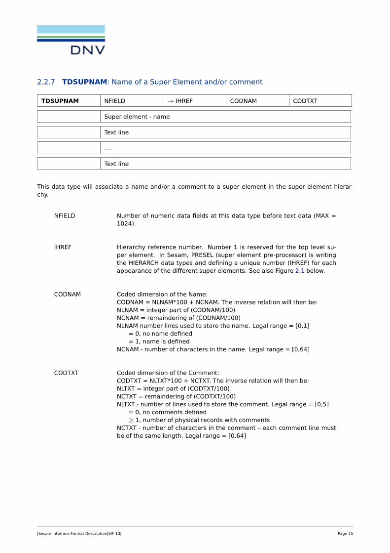
This data type will associate a name and/or a comment to a super element in the super element hierar-chy.
NFIELD Number of numeric data fields at this data type before text data (MAX =1024).
IHREF Hierarchy reference number. Number 1 is reserved for the top level su-per element. In Sesam, PRESEL (super element pre-processor) is writingthe HIERARCH data types and defining a unique number (IHREF) for eachappearance of the different super elements. See also Figure 2.1 below.
CODNAM Coded dimension of the Name:CODNAM = NLNAM*100 + NCNAM. The inverse relation will then be:NLNAM = integer part of (CODNAM/100)NCNAM = remaindering of (CODNAM/100)NLNAM number lines used to store the name. Legal range = [0,1]
= 0, no name defined= 1, name is defined
NCNAM - number of characters in the name. Legal range = [0,64]
CODTXT Coded dimension of the Comment:CODTXT = NLTXT*100 + NCTXT. The inverse relation will then be:NLTXT = integer part of (CODTXT/100)NCTXT = remaindering of (CODTXT/100)NLTXT - number of lines used to store the comment. Legal range = [0,5]
= 0, no comments defined≥ 1, number of physical records with comments
NCTXT - number of characters in the comment – each comment line mustbe of the same length. Legal range = [0,64]
|Sesam Interface Format Description|SIF 10| Page 15

Figure 2.1: Super element hierarchy with 3 levels.
In Figure 2.1 above, please notice that N2, N3, N4, and N5 may take any values as long as they are uniquein the hierarchy. Further notice that the top level super element has IHREF = 1 as required for the top levelsuper element.
Back to Section 2.2 Text Data
|Sesam Interface Format Description|SIF 10| Page 16

2.2.8 TEXT: User supplied Text
TEXT TYPE SUBTYPE NRECS NBYTE
. . .
The identifier is used to transfer text strings on the interface file. The following NRECS records must beread in A-format, 72 characters per record.
TYPE Value giving information of how to use this text
= 1 Texts describing this analysis/global text
= 2 Texts concerning current super element
= 3 Text concerning specific load cases
≥ 4 The meaning of text to be mutually agreed on by pre-processor andanalysis program
SUBTYPE Value giving additional information to TYPE
Example: For TYPE = 3, SUBTYPE gives load case number.
NRECS Number of records following to be read in A-format. NRECS ≥ 1
NBYTE Number of significant bytes (characters) on the following NRECS records.
1 ≤ NBYTE ≤ 72
The eight first bytes on the text records shall be filled with blanks.
Back to Section 2.2 Text Data
|Sesam Interface Format Description|SIF 10| Page 17
2.2.9 TSLAYER: Name of a General Eccentric Sandwich Type and/or comment
TSLAYER NFIELD → GEONO CODNAM CODTXT
Name
Comment line
. . .
Comment line
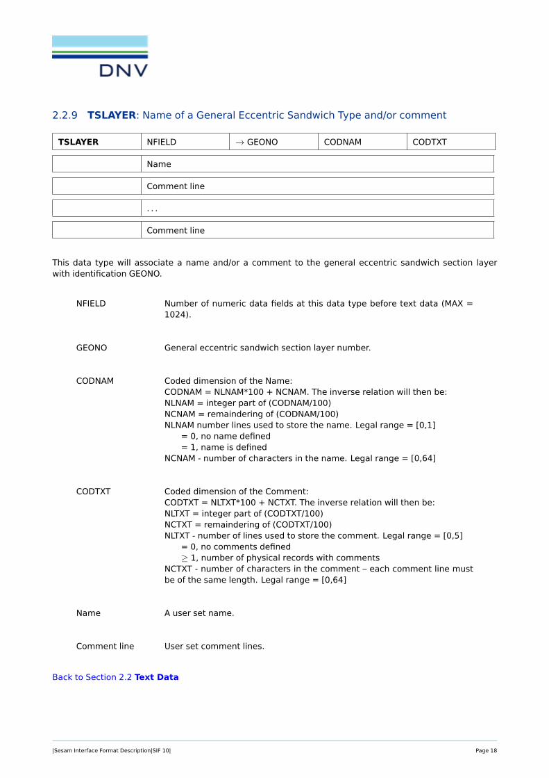
This data type will associate a name and/or a comment to the general eccentric sandwich section layerwith identification GEONO.
NFIELD Number of numeric data fields at this data type before text data (MAX =1024).
GEONO General eccentric sandwich section layer number.
CODNAM Coded dimension of the Name:CODNAM = NLNAM*100 + NCNAM. The inverse relation will then be:NLNAM = integer part of (CODNAM/100)NCNAM = remaindering of (CODNAM/100)NLNAM number lines used to store the name. Legal range = [0,1]
= 0, no name defined= 1, name is defined
NCNAM - number of characters in the name. Legal range = [0,64]
CODTXT Coded dimension of the Comment:CODTXT = NLTXT*100 + NCTXT. The inverse relation will then be:NLTXT = integer part of (CODTXT/100)NCTXT = remaindering of (CODTXT/100)NLTXT - number of lines used to store the comment. Legal range = [0,5]
= 0, no comments defined≥ 1, number of physical records with comments
NCTXT - number of characters in the comment – each comment line mustbe of the same length. Legal range = [0,64]
Name A user set name.
Comment line User set comment lines.
Back to Section 2.2 Text Data
|Sesam Interface Format Description|SIF 10| Page 18

3 ELEMENT TYPES
Conventions for use of the interface file for the elements in Sesam are defined here. Other element typesmay be introduced for use in other programs.
The table below contains element type numbers already reserved. (Not all of them are included in Sesam).
Id Description Element Type Section
BEPS Beam Element for Plane Systems 2 see Section 3.1
CSTA Plane Constant Strain Triangle 3 see Section 3.2
ILST Plane Linear Strain Triangle 6 see Section 3.3
IQQE Plane Isoparametric Quadrilateral Membrane Element 8 see Section 3.4
LQUA Plane Incompatible Linear Quadrilateral Membrane Ele-ment
9 see Section 3.5
TESS Truss Element 10 see Section 3.6
GMAS 1-Noded Mass Element 11 see Section 3.7
GLMA General 2-Noded Mass Element 12 see Section 3.8
GLDA General 2-Noded Damping Element 13 see Section 3.9
BEAS Beam Element 15 see Section 3.10
AXIS Axial Spring 16 see Section 3.11
AXDA Axial Damper 17 see Section 3.12
GSPR Ground Spring 18 see Section 3.13
GDAM Damper to Ground 19 see Section 3.14
IHEX Iso-parametric Hexahedron 20 see Section 3.15
LHEX Linear Hexahedron 21 see Section 3.16
SECB Sub-parametric Curved Beam 22 see Section 3.17
BTSS Sub-parametric General Curved Beam 23 see Section 3.18
FQUS Flat Quadrilateral Thin Shell 24 see Section 3.19
FTRS Flat Triangular Thin Shell 25 see Section 3.20
SCTS Sub-parametric Curved Triangular Shell 26 see Section 3.21
MCTS Sub-parametric Multi-layered Curved Triangular Shell 27 see Section 3.22
SCQS Sub-parametric Curved Quadrilateral Shell 28 see Section 3.23
MCQS Sub-parametric Multilayered Curved Quadrilateral Shell 29 see Section 3.24
IPRI Iso-parametric Prism 30 see Section 3.25
ITET Iso-parametric Tetrahedron 31 see Section 3.26
TPRI Triangular Prism 32 see Section 3.27
TETR Tetrahedron 33 see Section 3.28
LCTS Sub-parametric Layered Curved Triangular Shell 34 see Section 3.29
continued . . .
|Sesam Interface Format Description|SIF 10| Page 19

Id Description Element Type Section
LCQS Sub-parametric Layered Curved Quadrilateral Shell 35 see Section 3.30
TRSI Transition Elements between Solids and Shells 36, 37, or 38 see Section 3.31
GLSH General 2-Noded Spring / Shim Element 40 see Section 3.32
AXCS Axi-symmetric Constant Strain Triangle 41 see Section 3.33
AXLQ Axi-symmetric Constant Strain Quadrilateral 42 see Section 3.34
AXLS Axi-symmetric Linear Strain Triangle 43 see Section 3.35
AXQQ Axi-symmetric Linear Strain Quadrilateral 44 see Section 3.36
CTCP 2-Noded (1+1) Contact Element 51 see Section 3.37
CTCL 4-Noded (2+2) Contact Element 52 see Section 3.38
CTAL 4-Noded (2+2) Axi-symmetric Contact Element 53 see Section 3.39
CTCC 6-Noded (3+3) Contact Element 54 see Section 3.40
CTAQ 6-Noded (3+3) Axi-symmetric Contact Element 55 see Section 3.41
CTLQ 8-Noded (4+4) Contact Element 56 see Section 3.42
CTCQ 16-Noded (8+8) Contact Element 57 see Section 3.43
CTMQ 18-Noded (9+9) Contact Element 58 see Section 3.44
FTAS Flat Triangular Thin Shell – Drilling degree of freedom 59 see Section 3.45
FQAS Flat Quadrilateral Thin Shell – Drilling degree of free-dom
60 see Section 3.46
HCQS Heterosis Curved Quadrilateral Shell 61 see Section 3.47
THTS Flat 3-noded Thick Triangular Shell 63 see Section 3.48
THQS Flat 4-noded Thick Quadrilateral Shell 64 see Section 3.49
MATR General Matrix Element 70 see Section 3.50
GHEX General Hexahedron 100, . . . , 163 see Section 3.51
|Sesam Interface Format Description|SIF 10| Page 20

3.1 BEPS: Beam Element for Plane Systems
Element Type 2.
INPUT INTERFACE FILE SESAMPage Date Program Version5-6 01-NOV-1996 6
ELTYP=2: Beam Element for Plane Systems (BEPS) BEPS(2)
• 2 nodes• 6 degrees of freedom, 3 (u,v and q) at each of the two nodes• Bending, shear and axial deformations are considered• The element is straight and has a constant cross section• offset nodes (i.e. the nodes may be located eccentric in space)• element loads:
- load linearly distributed over all, or a part, of the element (Figure 5-1 b)- gravitational load - general inertia load- initial strain (temperature load)
Figure 5-1 a)2−D Beam Element b)Linearly Distributed Load
Element coordinate system (reference axes):
The local x-axis is directed along the beam, coinciding with the center of gravity and pointing from the beamnode "1" to node "2". The local z-axis is defined on GUNIVEC-record.
ex1
ey1
y (v)
x (u)
ey2
ex2
node "2"
node "1"
a) b)
|Sesam Interface Format Description|SIF 10| Page 21

SESAM INPUT INTERFACE FILEProgram Version Date Page6 01-NOV-1996 5-7
Data types used for this element:
GELMNT1 *GELREF1 *GBEAMG *GIORH, GUSYI, GCHAN, GBOX, GPIPE, GBARM, GTONP or GDOBO;for SESTRA these reecords are transferred to postprocessor, and only referred when storing on result file.
MISOSEL *GUNIVEC *GECCENBELOAD1BGRAVBNACCLOBEISTE BELFIX
*) Mandatory
BEPS(2)
Back to Section 3 ELEMENT TYPES
|Sesam Interface Format Description|SIF 10| Page 22

3.2 CSTA: Plane Constant Strain Triangle
Element Type 3, see reference [7]
INPUT INTERFACE FILE SESAMPage Date Program Version5-8 01-NOV-1996 6
ELTYP=3: Plane Constant Strain Triangle (CSTA), /2/ CSTA(3)
• 3 nodes• 3 x 2 degrees of freedom• straight (two dimensional)• linearly varying thickness• deformation considered: translational strain• element loads:
- line loads- initial strain (temperature load)- gravitational load (only in the mebrane plane)- general inertia load (only in the membrane plane)
• isotropic or anisotropic material data
Local node numbering:
Figure 5-2 Plane constant strain triangle.
When line load is specified, the relation between local node numbers and loaded line will be:
Line 1 means load along the line defined by the nodes 2 and 3.Line 2 means load along the line defined by the nodes 1 and 3.Line 3 means load along the line defined by the nodes 1 and 2.
The direction of node numbering can be as well clockwise as counterclockwise.
v2
y, v
x, u
u22
1
3
u3
v1
u1
Global coordinates
v3
|Sesam Interface Format Description|SIF 10| Page 23

SESAM INPUT INTERFACE FILEProgram Version Date Page6 01-NOV-1996 5-9
Data types used for this element:
GELMNT1 *GELREF1 *GNODE *GCOORD *GELTH *
MISOSEL * orMORSMEL *MTRMEL
BELLO2BEISTEBGRAVBNACCLO
*) Mandatory
CSTA(3)
Back to Section 3 ELEMENT TYPES
|Sesam Interface Format Description|SIF 10| Page 24

3.3 ILST: Plane Linear Strain Triangle
Element Type 6, see reference [7]
INPUT INTERFACE FILE SESAMPage Date Program Version5-10 01-NOV-1996 6
ELTYP=6: Plane Linear Strain Triangle (ILST), /2/ ILST(6)
• 6 nodes• 6 x 2 degrees of freedom• curved (two-dimensional)• linearly varying thickness• deformations considered: translational strain• element loads:
- line loads- initial strain (temperature loads)- gravitational load- general inertia load
• isotropic or anisotropic material data
Local node numbering:
Figure 5-3 Plane linear strain triangle.
When line load is specified, the relation between local node numbers and loaded line will be:
Line 1 means load along the line defined by the nodes 2, 5 and 3.Line 2 means load along the line defined by the nodes 1, 6 and 3.Line 3 means load along the line defined by the nodes 1, 4 and 2.
The direction of node numbering can be as well clockwise as counterclockwise.
v2
y, v
x, u
u22
1
3
v3
u3
v1
u1
Global coordinates
56
4
|Sesam Interface Format Description|SIF 10| Page 25

SESAM INPUT INTERFACE FILEProgram Version Date Page6 01-NOV-1996 5-11
The following restrictions are put on the data types
GELINT The integration stations must be distributed according to the Gaussian integration scheme,i.e.INTYPE =1. For this element type the GELINT specifications consist of the first filerecord(line) only.
Stiffness matrix: For stiffness matrix calculations the number of integration stations will be the same in both coordinate directions and equal to the value specified for N1.Legal values are 3 and 4.Default value is 3.
Mass matrix: For mass matrix calculations the number of integration stations will be thesame in both coordinate directions and equal to the value specified for N1.Legal values are 1,3,4 and 7.Default value is 7.
Load vector: For load vector calculations due to initial strains the number of integration stations will be the same in both coordinate directions and equal to the value specified forN1.Legal values are 1,3 and 4.Default value is 3.
Data types used for this element:
GELMNT1 *GELREF1 *GNODE *GCOORD *GELTH *GELINTMISOSEL or MORSMEL *
MTRMELBELLO2BEISTEBGRAVBNACCLO
*) Mandatory
ILST(6)
Back to Section 3 ELEMENT TYPES
|Sesam Interface Format Description|SIF 10| Page 26

3.4 IQQE: Plane Isoparametric Quadrilateral Membrane Element
Element Type 8, see reference [7]
INPUT INTERFACE FILE SESAMPage Date Program Version5-12 01-NOV-1996 6
ELTYP=8: Plane Quadril. Membrane Element (IQQE), /2/ IQQE(8)
• 8 nodes• 8 x 2 degrees of freedom• curved (two-dimensional)• linearly varying thickness• deformations considered: translational strain• element loads:
- line loads- initial strain (temperature loads)- gravitational load- general inertia load
• isotropic or anisotropic material data
Local node numbering:
Figure 5-4 Plane quadrilateral membrane element.
When line load is specified, the relation between local node numbers and loaded line will go:
LINE 1 means load along the line defined by the nodes 2, 6 and 3LINE 2 means load along the line defined by the nodes 5 and 7LINE 3 means load along the line defined by the nodes 1, 8 and 4LINE 4 means load along the line defined by the nodes 1, 5 and 2LINE 5 means load along the line defined by the nodes 8 and 6LINE 6 means load along the line defined by the nodes 4, 7 and 3
v
y
x
1
Global coordinates
4
2
5
3
8u
7
6
SESAM INPUT INTERFACE FILEProgram Version Date Page6 01-NOV-1996 5-13
The direction of node numbering can be as well clockwise as counterclockwise.
|Sesam Interface Format Description|SIF 10| Page 27

INPUT INTERFACE FILE SESAMPage Date Program Version5-14 01-NOV-1996 6
The following restrictions are put on the data types
GELINT The integration stations must be distributed according to the Gaussian integration scheme,i.e.INTYPE =1. For this element type the GELINT specifications consist of the first filerecord only.
Stiffness matrix: For stiffness matrix calculations the number of integration stations will be the same in both coordinate directions and equal to the value specified for N1.Legal values are 2, 3 and 4. Default value is 2.
Mass matrix: For mass matrix calculations the number of integration stations will be the same in both coordinate directions and equal to the value specified for N1.Legal values are 2, 3 and 4. Default value is 4.
Load vector: For load vector calculations due to initial strains the number of integration stations will be the same in both coordinate directions and equal to the value specified forN1.Legal values are 2, 3 and 4.Default value is 2.
BELLO2 LINE = 2, and LINE = 5 are not operative.
Data types used for this element:
GELMNT1 *GELREF1 *GNODE *GCOORD *GELTH *GELINTMISOSEL or MORSMEL *MTRMELBELLO2BEISTEBGRAVBNACCLO
*) Mandatory
IQQE(8)
Back to Section 3 ELEMENT TYPES
|Sesam Interface Format Description|SIF 10| Page 28

3.5 LQUA: Plane Incompatible Linear Quadrilateral Membrane Element
Element Type 9, see reference [7]
SESAM INPUT INTERFACE FILEProgram Version Date Page6 01-NOV-1996 5-15
ELTYP=9: Plane Quadrilateral Membrane Element LQUA(9)(LQUA), /2/
• 4 nodes• 4 x 2 degrees of freedom• straight (two-dimensional)• linearly varying thickness• isotropic or anisotropic material data• deformations considered: translational strain• element loads
- line loads- initial strain (temperature load)- gavitational load- general inertia load
Local node numbering:
Figure 5-5 Plane Quadrilateral Membrane Element.
When line load is specified, the relation between local node numbers and loaded line will go:
LINE 1 means load along the line defined by the nodes 1 and 2LINE 2 means load along the line defined by the nodes 2 and 3LINE 3 means load along the line defined by the nodes 3 and 4LINE 4 means load along the line defined by the nodes 4 and 1
The direction of node numbering can be as well clockwise as counterclockwise.
v
y
x
1
Global coordinates
4
2
3
u
|Sesam Interface Format Description|SIF 10| Page 29

INPUT INTERFACE FILE SESAMPage Date Program Version5-16 01-NOV-1996 6
Data types used for this element:
GELMNT1 *GELREF1 *GNODE *GCOORD *GELTH *GELINTMISOSEL or *MORSMELBELLO2MTRMELBEISTEBGRAVBNACCLO
*) Mandatory
The following restrictions are put on data types:
GELINT The integration stations must be distributed according to the Gaussian integration scheme,i.e.INTYPE =1. For this element type the GELINT specifications consist of the first line.
Stiffness matrix:Legal values for N1 and N2 are 1, 2, 3 and 4.Default value is N1=N2=2.
Mass matrix: For mass matrix calculations the number of integration stations will be thesamein both coordinate directions and equal to the value specified for N1.Legal values are 2 and 3.Default value is N1=N2=3.
LQUA(9)
Back to Section 3 ELEMENT TYPES
|Sesam Interface Format Description|SIF 10| Page 30

3.6 TESS: Truss Element
Element Type 10, see reference [7]
SESAM INPUT INTERFACE FILEProgram Version Date Page6 01-NOV-1996 5-17
ELTYP=10: Truss Element (TESS) /2/ TESS(10)
• 2 nodes• 2 x 3 = 6 degrees of freedom• straight• constant cross section• axial stiffness only• element loads:
- initial strain (temperature)
Figure 5-6 Truss element
Data types used for this element:
BEISTE
GELMNT1 *GBEAMG (only AREA) *GELREF1 *
MISOSEL
*) Mandatory
Back to Section 3 ELEMENT TYPES
|Sesam Interface Format Description|SIF 10| Page 31

3.7 GMAS: 1-Noded Mass Element
Element Type 11
INPUT INTERFACE FILE SESAMPage Date Program Version5-18 01-NOV-1996 6
ELTYP=11: 1-Noded Mass Element (GMAS) GMAS(11)
• 1 node• degrees of freedom, arbitrary• mass matrix
Figure 5-7 1-noded mass element
The mass point may be specified with eccentricities (ex, ey and ez) in all three global directions and the massmatrix may be specified in a transformed local coordinate system.
The mass matrix is a full symmetric matrix where all values on and below the diagonal are stored.
Data types used for this element:
GELMNT1 *MGMASS * (NDOF must be equal to NDOF on data type GNODE)GELREF1 *GECCENBNTRCOS (NDOF = 3 or 6 is required for transformations)
*) Mandatory
ex
ey
Back to Section 3 ELEMENT TYPES
|Sesam Interface Format Description|SIF 10| Page 32

3.8 GLMA: General 2-Noded Mass Element
Element Type 12
SESAM INPUT INTERFACE FILEProgram Version Date Page6 01-NOV-1996 5-19
ELTYP=12: General 2-Noded Mass Element (GLMA) GLMA(12)
• 2 nodes• degrees of freedom, arbitrary• general mass matrix
Figure 5-8 General 2-noded mass element.
The resulting mass matrix is a full symmetric matrix where all values on and below the main diagonal arestored.
Data types used for this element:
GELMNT1 *MGLMASS * (NDOF1 and NDOF2 must be equal to NDOF on data type GNODE for "node 1" and "node 2")GELREF1 * BNTRCOS (Transformation in the two nodes may be different. But NDOF1 = NDOF2 = 3 or 6 is requiredfor transformation).
*) Mandatory
"node 1"
"node 2"
Back to Section 3 ELEMENT TYPES
|Sesam Interface Format Description|SIF 10| Page 33
3.9 GLDA: General 2-Noded Damping Element
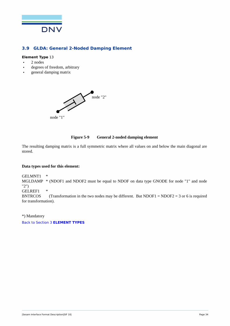
Element Type 13
INPUT INTERFACE FILE SESAMPage Date Program Version5-20 01-NOV-1996 6
ELTYP=13: General 2-Noded Damping Element (GLDA) GLDA(13)
• 2 nodes• degrees of freedom, arbitrary• general damping matrix
Figure 5-9 General 2-noded damping element
The resulting damping matrix is a full symmetric matrix where all values on and below the main diagonal arestored.
Data types used for this element:
GELMNT1 *MGLDAMP * (NDOF1 and NDOF2 must be equal to NDOF on data type GNODE for node "1" and node"2")GELREF1 *BNTRCOS (Transformation in the two nodes may be different. But NDOF1 = NDOF2 = 3 or 6 is requiredfor transformation).
*) Mandatory
node "1"
node "2"
Back to Section 3 ELEMENT TYPES
|Sesam Interface Format Description|SIF 10| Page 34

3.10 BEAS: Beam Element
Element Type 15, see reference [7]
• 2 nodes
• 2 × 6 = 12 degrees of freedom
• straight
• constant cross section
• offset nodes (i.e. the nodes may be located eccentrically in space)
• deformations considered: bending and shear about the two principal axes, axial deformations and St.Venant torsion
• the transverse load must be located in the shear centre of the beam
• eccentric shear centre
• element loads:
– load linearly distributed over all, or a part, of the element (see Figure 3.1 b))
– gravitational load
– general inertia load
– initial strain (temperature load)
Element co-ordinate system (reference axes):
SESAM INPUT INTERFACE FILEProgram Version Date Page6 01-NOV-1996 5-21
ELTYP=15: Beam Element (BEAS) /2/ BEAS(15)
• 2 nodes• 2 x 6 = 12 degrees of freedom• straight• constant cross section• offset nodes (i.e. the nodes may be located eccentrically in space)• deformations considered: bending and shear about the two principal axes, axial deformations and
St.Venant torsion• the transverse load must be located in the shear centre of the beam• eccentric shear center• element loads:
- load linearly distributed over all, or a part, of the element (Figure 5-10 b)- gravitational load - general inertia load- initial strain (temperature load)
Figure 5-10 a)Beam element b)Linearly distributed load
Element coordinate system (reference axes). The local x-axis is directed along the beam, coinciding with thecenter of gravity and pointing from node "1" to node "2". The local z-axis is defined on GUNIVEC-record.
a) b)Figure 3.1: a) A beam element b) Linearly distributed load
The local x-axis is directed along the beam, coinciding with the centre of gravity and pointing from node "1"to node "2". The local z-axis is defined on the GUNIVEC data type.
|Sesam Interface Format Description|SIF 10| Page 35

Data types used for this element:
Data type Mandatory Note
GELMNT1 yes
GBEAMG yes The following data types can be used to specify the cross-section ofa BEAS element:
GIORH, GUSYI, GCHAN, GBOX, GPIPE, GBARM, GTONP or,GDOBO
for Sestra these data types are transferred to post-processor, andonly referred when storing on result file
GELREF1 yes
MISOSEL yes
GUNIVEC yes
GECCEN
BEDRAG1
BEMASS1
BELOAD1
BGRAV
BNACCLO
BEISTE
BELFIX
Back to Section 3 ELEMENT TYPES
|Sesam Interface Format Description|SIF 10| Page 36

3.11 AXIS: Axial Spring
Element Type 16
SESAM INPUT INTERFACE FILEProgram Version Date Page6 01-NOV-1996 5-23
ELTYP=16: Axial Spring (AXIS) AXIS(16)
• 2 nodes• degrees of freedom at each node: 2, 3 or 6• axial stiffness
Figure 5-11 Axial spring
Data types used for this element:
GELMNT1 *GELREF1 *MAXSPR *
*) Mandatory
Back to Section 3 ELEMENT TYPES
|Sesam Interface Format Description|SIF 10| Page 37

3.12 AXDA: Axial Damper
Element Type 17
INPUT INTERFACE FILE SESAMPage Date Program Version5-24 01-NOV-1996 6
ELTYP=17: Axial Damper (AXDA) AXDA(17)
• 2 nodes• degrees of freedom at each node: 2, 3 or 6.• axial damping
Figure 5-12 Axial damper.
Data types used for this element:
GELMNT1 *GELREF1 *MAXDMP *
*) Mandatory
Back to Section 3 ELEMENT TYPES
|Sesam Interface Format Description|SIF 10| Page 38

3.13 GSPR: Ground Spring
Element Type 18
SESAM INPUT INTERFACE FILEProgram Version Date Page6 01-NOV-1996 5-25
ELTYP=18: Ground Spring (GSPR) GSPR(18)
• 1 node• degrees of freedom, arbitrary• stiffness matrix
Figure 5-13 Ground spring
Data types used for this element:
GELMNT1 *GELREF1 *MGSPRNG * (NDOF must be equal to NDOF on data type GNODE)BNTRCOS (NDOF = 3 or 6 is required for transformations)
*) Mandatory
Back to Section 3 ELEMENT TYPES
|Sesam Interface Format Description|SIF 10| Page 39

3.14 GDAM: Damper to Ground
Element Type 19
INPUT INTERFACE FILE SESAMPage Date Program Version5-26 01-NOV-1996 6
ELTYP=19: Damper to Ground (GDAM) GDAM(19)
• 1 node• degrees of freedom arbitrary• damping matrix
Figure 5-14 Damper to ground
Data types used for this element:
GELMNT1 *GELREF1 *MGDAMP * (NDOF must be equal to NDOF on data type GNODE)BNTRCOS (NDOF = 3 or 6 is required for transformations)
*) Mandatory
Back to Section 3 ELEMENT TYPES
|Sesam Interface Format Description|SIF 10| Page 40

3.15 IHEX: Iso-parametric Hexahedron
Element Type 20, see reference [7]
SESAM INPUT INTERFACE FILEProgram Version Date Page6 01-NOV-1996 5-27
ELTYP=20: Isoparametric Hexahedron (IHEX), /2/ IHEX(20)
• 20 nodes• 20 x 3 degrees of freedom• curved element sides• isotropic or anisotropic material data• deformations considered: translational strain• element loads:
- initial strain (temperature load)- surface forces- line loads- gravitational load- general inertia load
Figure 5-15 Isoparametric hexahedron with local nodenumbering and corresponding surfacenumbering
4
3
1 2
6
5
7
8
23
4
56
12
910
11
19
20
1415
16
1718
1
13 local node no. 11
surface no. 6
ζ
ξ
η
|Sesam Interface Format Description|SIF 10| Page 41

INPUT INTERFACE FILE SESAMPage Date Program Version5-28 01-NOV-1996 6
Figure 5-16 Typical isoparametric hexahedron
When surface loads are specified for the element side, the surface numbers shown are used for identification ofthe side in question.
The local node numbering for each side is defined as follows:
Node number
1 2 3 4 5 6 7 8Side no.
1 7 8 1 9 13 20 19 122 5 11 17 16 15 10 3 43 1 2 3 10 15 14 13 94 7 12 19 18 17 11 5 65 7 6 5 4 3 2 1 86 19 20 13 14 15 16 17 18
IHEX(20)
z
x
y 1
23
4
5
6
15
10
11
16
12
7
20
13
914
8
19
1817
ξ=-1
η=-1
ξ
ηζ
ξ=+1
η=+1
|Sesam Interface Format Description|SIF 10| Page 42

SESAM INPUT INTERFACE FILEProgram Version Date Page6 01-NOV-1996 5-29
When line load is specified, the relation between the local node numbers and the loaded line will be as follows:
Node number1 2 3
Line no.1 1 2 32 3 4 53 5 6 74 7 8 15 1 9 136 3 10 157 5 11 178 7 12 199 13 14 15
10 15 16 1711 17 18 1912 19 20 1313 8 414 6 215 9 1016 2 1417 10 1118 4 1619 11 1220 6 1821 12 922 8 2023 20 1624 14 18
IHEX(20)
|Sesam Interface Format Description|SIF 10| Page 43

INPUT INTERFACE FILE SESAMPage Date Program Version5-30 01-NOV-1996 6
Data types used for this element:
GELMNT1 *GNODE *GCOORD *GELREF1 *GELSTRPMISOSEL * orMISOPL * orMORSSOL *MTRSOLBEUSLOBELLO2BEISTEBGRAVBNACCLO
*) Mandatory
IHEX(20)
|Sesam Interface Format Description|SIF 10| Page 44

SESAM INPUT INTERFACE FILEProgram Version Date Page6 01-NOV-1996 5-31
The following restrictions are put on the data types
GELINT The integration stations must be distributed according to the Gaussian integration scheme,i.e. INTYPE=1. For this element type the GELINT specifications consist of the first twolines.
Stiffness matrix: For stiffness matrix calculations the number of integration stations will be the same in all coordinate directions and equal to the value specified for N1.Legal values are 2, 3 and 4.For a regular element N1 = 2 may cause a singular stiffness matrix.Default value is 3.
Load calculations: Here, the number of integration stations in each coordinate direction mustbe specified individually. If volume forces are calculated, legal values for N1, N2 and N3 are2, 3 and 4.For surface forces, the legal value for N1, N2 and N3 is 2.Default value is 2.
Initial strain: The number of integration stations in each coordinate direction must be speci-fied individually.Legal values for N1, N2 and N3 are 2, 3 and 4. Default value is 2.
Mass matrix: Again the number of integration stations in each direction must be specified in-dividually.Legal values for N1, N2 and N3 are 3 and 4.Default value is 3.
GELSTRP The stress points must be distributed according to the Gaussian integration scheme, i.e.STRPTYP=1. Only the first two records of the GELSTRP specification are therefore used inthis element type.Legal values for N1, N2 and N3 are 1, 2, 3 and 4.Default value is 2.
BELLO2 The SIDE definition is not used. The load components are given nodewise in globalcoordinates.
BEUSLO Only one side can be loaded for each BEUSLO record. For the same reason only one sideidentification may be given in SIDE on the BEUSLO record.
IHEX(20)
Back to Section 3 ELEMENT TYPES
|Sesam Interface Format Description|SIF 10| Page 45

3.16 LHEX: Linear Hexahedron
Element Type 21, see reference [7]
INPUT INTERFACE FILE SESAMPage Date Program Version5-32 01-NOV-1996 6
ELTYP=21: Linear Hexahedron (LHEX), /2/ LHEX(21)
• 8 nodes• 8 x 3 = 24 degrees of freedom• linear element sides• isotropic or anisotropic material data• deformation considered: translational displacement• element load
- gravitational load- general inertia load- initial strain (temperature load)- surface forces- line loads
Figure 5-17 Linear hexahedron solid element with local nodenumbering and corresponding surfacenumbering.
1
2
y
x
z
3
4
5
6
7
81
2
34
5
6
|Sesam Interface Format Description|SIF 10| Page 46

SESAM INPUT INTERFACE FILEProgram Version Date Page6 01-NOV-1996 5-33
When surface loads are specified for an element side, the surface numbers shown are used for identification ofthe surface in question.The local nodenumbering for each side is defined as follows:
Node number1 2 3 4
Side no.1 5 6 7 82 1 2 6 53 2 3 7 64 3 4 8 75 4 1 5 86 1 4 3 2
When line load is specified, the relation between the local node numbers and the loaded line will be as follows:
Node number1 2
Line no.1 1 22 2 33 3 44 4 15 1 56 2 67 3 78 4 89 5 610 6 711 7 812 8 5
LHEX(21)
|Sesam Interface Format Description|SIF 10| Page 47

INPUT INTERFACE FILE SESAMPage Date Program Version5-34 01-NOV-1996 6
Data types used for this element:
GELMNT1 *GNODE *GCOORD *GELREF1 *MISOSEL * orMORSSOL *BELLO2BEUSLOBEISTEBGRAVBNACCLO
*) Mandatory
LHEX(21)
|Sesam Interface Format Description|SIF 10| Page 48

SESAM INPUT INTERFACE FILEProgram Version Date Page6 01-NOV-1996 5-35
The following restrictions are put on data type:
GELINT The integration stations must be distributed according to the Gaussian integration scheme,i.e. INTYPE = 1. For this element type the GELINT specifications consist of only the firstline.
Stiffness matrix calculation: Number of integration stations will be the same in all coordinatedirections and equal to the value specified for N1.Legal values are 2 and 3.Default value is 2.
Load calculations: Number of integration stations is the same in all coordinate directions. The only legal value is N1=2.
Initial strain: Number of integration stations is the same in all coordinate directions and isgiven by N1.Legal values are 2 and 3.Default value for N1 is 2.
Mass matrix calculation: The same number of integration points in each coordinate directionas in stiffness matrix calculation is also used in mass matrix calculation.
GELSTRP The stress points must be distributed according to the Gaussian integration scheme, i.e. STRPTYP=1. Number of stress points in each of the coordinate directions are the same andequal to the number specified by N1. Only the first record of the GELSTRP specification istherefore used for this element type.Legal values of N1 are 2 and 3.The default value is 2.
BELLO2 The SIDE definition is not used. The load components are given nodewise in globalcoordinates.
BEUSLO An element side may only be loaded once for each BEUSLO-record.
LHEX(21)
Back to Section 3 ELEMENT TYPES
|Sesam Interface Format Description|SIF 10| Page 49

3.17 SECB: Sub-parametric Curved Beam
Element Type 22, see reference [7]
INPUT INTERFACE FILE SESAMPage Date Program Version5-36 01-NOV-1996 6
ELTYP=22: Subparametric Curved Beam (SECB) /2/ SECB(22)
• 3 nodes• 3 x 6 degrees of freedom• curved element• isotropic material data• deformations considered:
bending, shear and axial strain• element loads:
- line loads- gravitational load- general inertia load
Figure 5-18 Typical beam elementGlobal cartesian - local curvilinear coordinate system
X
η
Y
Z
1
2 3
ζ
ξ
|Sesam Interface Format Description|SIF 10| Page 50

SESAM INPUT INTERFACE FILEProgram Version Date Page6 01-NOV-1996 5-37
Figure 5-19 Cross-section data, for the beam element.
Data types used for this element:
GELMNT1 *GELREF1 *MISOSEL *GUNIVEC *GECCENGELINTGBARM *BELLO2BGRAVBNACCLO
*) Mandatory
SECB(22)
x’
t1
t2e2
e1
y’ζ
ζ = 1
ζ = - 1
η = -1
η = 1
η
ξ
V3
V3
|Sesam Interface Format Description|SIF 10| Page 51

INPUT INTERFACE FILE SESAMPage Date Program Version5-38 01-NOV-1996 6
The following restrictions are put on the data-types.
GECCEN For this element only eccentricities in the local (h, z)-plane is allowed.
GELINT The integration stations must be distributed according to the Gaussian integration scheme,i.e. INTYPE=1. For this element type the GELINT specifications consist of the first twolines.
Stiffness matrix: Here, the number of integration stations in each coordinate direction mustbe specified individually. N1 must always be equal to 2. Legal values for N2 and N3 are 1and 2. In the directions where one integration station is specified, analytical integration isused, else numerical integration is used. Default value for N1, N2 and N3 is 2.
Load calculations: Only the number of integration stations in the first coordinate direction isused (line load along beam axis). Legal values are 2, 3 or 4. Default value for N1 is 2.
Mass matrix: As for stiffness matrix calculations.
GBARM Since the element cross-section must be rectangular, only H2I and BT are needed to specifythe cross-section geometry at a node.
BELLO2 LINE and SIDE will not be employed for this element.
SECB(22)
Back to Section 3 ELEMENT TYPES
|Sesam Interface Format Description|SIF 10| Page 52

3.18 BTSS: Sub-parametric General Curved Beam
Element Type 23, see reference [7]
SESAM INPUT INTERFACE FILEProgram Version Date Page6 01-NOV-1996 5-39
ELTYP=23: Subparam. General Curved Beam /2/ & /12/ BTSS(23)
• 3 nodes• 3 x 6 degrees of freedom• curved element• isotropic material data• constant cross section along the beam• general cross section• offset nodes (i.e. the nodes may be located eccentrically in space)• deformations considered: bending and shear, axial deformations and St.Venant torsion• the transverse load must be located in the shear centre of the beam• eccentric shear center• element loads:
- line load- line moment load- gravitational load- general inertia load- temperature load
Figure 5-20 Typical general beam elementGlobal cartesian - local curvilinear coordinate system
X
η
Y
Z
2 3
ζ
ξ
A (cross sectional area)
1
|Sesam Interface Format Description|SIF 10| Page 53

INPUT INTERFACE FILE SESAMPage Date Program Version5-40 01-NOV-1996 6
Data types used for this element:
GELMNT1 *GELREF1 *MISOSEL *GUNIVEC *GECCENGBEAMG *GELREF1 *GIORH, GUSYI, GCHAN, GBOX, GPIPE, GBARM, GTONP or,GDOBO;for SESTRA these records are transferred to postprocessor, and only referred when storing on result file.
BELLO2BGRAVBNACCLOBEISTE
*) Mandatory
The following restrictions are put on the data-types.
GECCEN General eccentricities in the local (ξ, η, ζ)-directions are allowed.
GBEAMG Cross section properties are fetched from this record in SESTRA. Geometry of cross sec-tions specified on other records (GBARM, GIORH etc.) are only transferred to the result file.
BELLO2 LINE and SIDE will not be employed for this element.
BTSS(23)
Back to Section 3 ELEMENT TYPES
|Sesam Interface Format Description|SIF 10| Page 54

3.19 FQUS: Flat Quadrilateral Thin Shell
Element Type 24, see reference [7]
SESAM INPUT INTERFACE FILEProgram Version Date Page6 01-NOV-1996 5-41
ELTYP=24: Flat Quadrilateral Thin Shell (FQUS), /2/ FQUS(24)
• 4 nodes• 4 x 5 degrees of freedom• linear element sides• isotropic or anisotropic material data• deformations considered:
bending, shear and translational strain• constant element thickness• element loads:
- initial strain (temperature loads)- surface forces- line loads- line moment load- gravitational load- general inertia loade
Figure 5-21 Element node numbering on flat quadrilateral shell element.
x
1
4
2
3
y
z
|Sesam Interface Format Description|SIF 10| Page 55

INPUT INTERFACE FILE SESAMPage Date Program Version5-42 01-NOV-1996 6
When line load is specified, the relation between local node numbers and loaded line will be:
LINE =1 means line load between node 1 and 2LINE =2 means line load between node 2 and 3LINE =3 means line load between node 3 and 4LINE =4 means line load between node 4 and 1
Data types for this element:
GELMNT1 *GNODE *GCOORD *GELREF1 *GELTH *MISOSEL * orMORSMEL *MTRMELBEUSLOBELLO2BEISTEBGRAVBNACCLO
*) Mandatory
FQUS(24)
|Sesam Interface Format Description|SIF 10| Page 56

The following restrictions apply to the data types:
GELREF1 - INTNO and ISPONO are not read because number of integration and stress points are con-stant in the program and can not be set by user.
- No thickness variation is allowed for this element. If thickness variation is specified by theGEONO / OPT option, the finite element program executing this element must use a meanthickness calculated from the nodal thicknesses.
BELLO2 - The SIDE definition is not used.
BEUSLO - This element type is only able to calculate surface loads which are acting perpendicular tothe element surface. For LOTYP=2 (loads given in component form), the in-plane compo-nents are ignored by the program.
SESAM INPUT INTERFACE FILEProgram Version Date Page6 01-NOV-1996 5-43
The following restrictions are put on the data types:
GELREF - INTNO and ISPONO are not read because number of integration and stress points areconstant in the program and can not be set by user.- No thickness variation is allowed for this element. If thickness variation is specifed bythe GEONO / OPT option, the finite element program executing this element must use amean thickness calculated from the nodal thicknesses.
BEUSLO This element type is only able to calculate surface loads which are acting perpendicular to theelement surface. Hence LOTYP=1 (normal pressure) should be used. If LOTYP=2 (loadsgiven in component form) are specified, the in-plane components are ignored by the program.Surface loads are always referred to the middle plane of these elements, i.e. SIDE=2 (neadnot be specified).
Figure 5-22 Linear variation of line load component normal to the element plane and in the plane.
FQUS(24)
x
1
4
2
3
y
z
Back to Section 3 ELEMENT TYPES
|Sesam Interface Format Description|SIF 10| Page 57

3.20 FTRS: Flat Triangular Thin Shell
Element Type 25, see reference [7]
INPUT INTERFACE FILE SESAMPage Date Program Version5-44 01-NOV-1996 6
ELTYP=25: Flat Triangular Thin Shell (FTRS), /2/ FTRS(25)
• 3 nodes• 3 x 5 degrees of freedom• linear element sides• isotropic or anisotropic material data• deformations considered:
bending, shear and translational strain• constant element thickness• element loads:
- initial strain (temperature loads)- surface forces- line loads- line moment load- gravitational load- general inertia load
Figure 5-23 Element node numbering and local area coordinates (A1, A2 and A3) on flat triangularshell element.
x
1
2
3
y
z
A2A1
A3
|Sesam Interface Format Description|SIF 10| Page 58

SESAM INPUT INTERFACE FILEProgram Version Date Page6 01-NOV-1996 5-45
When line load is specified for one of the element sides, the relation between local node numbers and loadedline will be:
LINE=1 means line load between node 2 and 3LINE=2 means line load between node 1 and 3LINE=3 means line load between node 1 and 2
Data types used for this element:
GELMNT1 *GNODE *GCOORD *GELREF1 *GELTH *MISOSEL *MORSMEL *MTRMELBEUSLOBELLO2BEISTEBGRAVBNACCLO
*) Mandatory
FTRS(25)
|Sesam Interface Format Description|SIF 10| Page 59

The following restrictions apply to the data types:
GELREF1 - INTNO and ISPONO are not read because number of integration and stress points are con-stant in the program and can not be set by user.
- GEONO / OPT should be set>0 because no thickness variation is allowed for this elementtype.
BELLO2 - The SIDE definition is not used.
BEUSLO - This element type is only able to calculate surface loads which are acting perpendicular tothe element surface. For LOTYP=2 (loads given in component form), the in-plane compo-nents are ignored by the program.
INPUT INTERFACE FILE SESAMPage Date Program Version5-46 01-NOV-1996 6
The following restrictions are put on the data types:
GELREF INTNO and ISPONO are not read because number of integration and stress points are con-stant in the program and cannot be set by user.GEONO / OPT should be set>0 because no thickness variation is allowed for this elementtype.
BEUSLO This element type is only able to calculate surface loads which are acting perpendicular to theelement surface. Hence LOTYP=1 (normal pressure) should be used. If LOTYP=2 (loadsgiven in component form) are specified, the in-plane components are ignored by the program.Surface loads are always referred to the middle plane of these elements, i.e. SIDE=2 (neednot be specified).
Figure 5-24 Constant line load in element plane and linear variation of component normal to the plane
FTRS(25)
x
1
2
3
y
z
Back to Section 3 ELEMENT TYPES
|Sesam Interface Format Description|SIF 10| Page 60

3.21 SCTS: Sub-parametric Curved Triangular Shell
Element Type 26, see reference [7]
SESAM INPUT INTERFACE FILEProgram Version Date Page6 01-NOV-1996 5-47
ELTYP=26: Subparametric Curved Triangular Shell SCTS(26)(SCTS), /2/
• 6 nodes• 6 x 6 degrees of freedom• curved element shape• isotropic or anisotropic material data• deformations considered:
bending, shear and translational strain• parabolically varying element thickness• element loads:
- initial strain- surface forces- line loads- line moment load- gravitational load- general inertia load
Figure 5-25 Element node numbering. Global Cartesian and local area coordinate system.
When line load is specified for one of the element sides, the relation between local node numbers and loadedline will be:
z
x
ζ= 1
ζ= -1
y
z
L1L3
L2
1
2
3
4
5
6
|Sesam Interface Format Description|SIF 10| Page 61

INPUT INTERFACE FILE SESAMPage Date Program Version5-48 01-NOV-1996 6
LINE=1 means line load on the element side defined by nodes 2, 5 and 3LINE=2 means line load on the element side defined by nodes 1, 6 and 3LINE=3 means line load on the element side defined by nodes 1, 4 and 2
The orientation of the local nodal coordinate system is related to the nodenumbering sequence (see Figure 5-25). The positive z-direction, normal to the element middle surface, is chosen according to the normal conven-tion of the right hand rule, i.e. the positive ζ-direction is found when the node numbers are followed in ascend-ing order, counterclockwise.
The SIDE definition on the BEUSLO records is as follows:
SIDE=1 means that load is given on the element surface where ζ=-1,SIDE=2 that ζ=0 is loaded, andSIDE=3 that ζ=1 is loaded.
Data types for this element:
GELMNT1 *GNODE *GCOORD *GELREF1 *GELINTGELTH *GELSTRPMISOSEL * orMORSSEL *MTRSELBEUSLOBELLO2BEISTEBGRAVBNACCLO
*) Mandatory
SCTS(26)
|Sesam Interface Format Description|SIF 10| Page 62

SESAM INPUT INTERFACE FILEProgram Version Date Page6 01-NOV-1996 5-49
The following restrictions are put on the data types.
GELINT The integration stations must be distributed according to a scheme similar to the Gaussianintegration scheme, i.e. INTYPE=1. For this element type the GELINT specifications consistof the first line only. The integration stations will be specified in the triangle plane, and notalong local coordinate axes. The value specified for N1 is not the number of integration sta-tions but a reference number to specified distributions of integration stations, which mayhave the same number of integration stations, but different positions in the triangle plane. Therefore, N3 has no meaning for this element type. Legal values for N1 are 1, 2, 3, 4, 5, 6,7, 8, 9, see description of subroutine HAMC30 in the finite element library, /2/. N2 ("ζ-direction") is not possible to specify and the value 2 is used for each layer. The integration inζ-direction will be performed analytically if max deviation from mean thickness is 5% andthe element is nearly flat.
Stiffness matrix: Default value for N1 is 7.
Load calculations: Default value for N1 is 6 for surface loads.
Initial strain: Default value for N1 is 6.
Mass matrix: N1 should be specified ³ 7 to ensure positive definite mass matrix. Defaultvalue is N1=7.
GELSTRP The stress points must be distributed according to the same scheme as the integration pointsin the GELINT specification, for stress point coordinates in the triangular plane. The stresspoint coordinates in the ζ-direction are distributed according to the usual Gaussian integra-tion scheme STRPTYP=1. Legal values for N1 are 1, 3, 4, 7, 9, and for N2 2, 3, 4.Default values for N1 is 3 and for N2 the default value is 2.Only the first record of the GELSTRP specification is used for this element type.
BELLO2 The SIDE-definition is not used.
SCTS(26)
Back to Section 3 ELEMENT TYPES
|Sesam Interface Format Description|SIF 10| Page 63

3.22 MCTS: Sub-parametric Multi-layered Curved Triangular Shell
Element Type 27
INPUT INTERFACE FILE SESAMPage Date Program Version5-50 01-NOV-1996 6
ELTYP=27: Subparametric Multilayered Curved MCTS(27)Triangular Shell (MCTS), /2/
• 6 nodes• 6 x 6 degrees of freedom• curved element shape• isotropic or anisotropic material data• two or more material layers (sandwich)• deformations considered:
bending, shear and translational strain• parabolically varying element thickness• element loads:
- initial strain- surface forces- line loads- line moment load- gravitational load- general inertia load
Figure 5-26 Element node numbering. Global Cartesian and local area coordinate system. Threelayers.
When line load is specified for one of the element sides, the relation between local node numbers and loadedline will be:
ζ
x
ζ= 1
ζ= -1
y
z
L1L3
L2
1
2
3
4
5
6
|Sesam Interface Format Description|SIF 10| Page 64

SESAM INPUT INTERFACE FILEProgram Version Date Page6 01-NOV-1996 5-51
LINE=1 means line load on the element side defined by nodes 2, 5 and 3LINE=2 means line load on the element side defined by nodes 1, 6 and 3LINE=3 means line load on the element side defined by nodes 1, 4 and 2
The orientation of the local nodal coordinate system is related to the nodenumbering sequence (see Figure 5-26). The positive ζ-direction, normal to the element middle surface, is chosen according to the normal conven-tion of the right hand rule, i.e. the positive ζ-direction is found when the node numbers are followed in ascend-ing order.
The SIDE definition on the BEUSLO records is as follows:
SIDE=1 means that load is given on the element surface where ζ=-1,SIDE=2 that ζ=0 is loaded, andSIDE=3 that ζ=1 is loaded.
Data types for this element:
GELMNT1 *GNODE *GCOORD *GELREF1 *GELINTGELTH *GELSTRPMORSSEL *MTRSELBEUSLOBELLO2BEISTEBGRAVBNACCLO
*) Mandatory
MCTS(27)
|Sesam Interface Format Description|SIF 10| Page 65
INPUT INTERFACE FILE SESAMPage Date Program Version5-52 01-NOV-1996 6
The following restrictions are put on the data types.
GELINT The integration stations must be distributed according to a scheme similar to the Gaussianintegration scheme, i.e. INTYPE=1. For this element type the GELINT specifications consistof the first line only. The integration stations will be specified in the triangle planes, and notalong local coordinate axes. The value specified for N1 is not the number of integration sta-tions but a reference number to specified distributions of integration stations, which mayhave the same number of integration stations, but different positions in the triangle planes. Therefore, N3 has no meaning for this element type. Legal values for N1 are 1, 2, 3, 4, 5, 6,7, 8, 9, see description of subroutine HAMC30 in the finite element library, /2/. N2 ("ζ-direction") is not possible to specify and the value 2 is used for each layer. The integration inζ-direction will be performed analytically if max deviation from mean thickness is 5% andthe element is nearly flat.
Stiffness matrix: Default value for N1 is 7.
Load calculations: Default value for N1 is 6 for surface loads.
Initial strain: Default value for N1 is 6.
Mass matrix: N1 should be specified ³ 7 to ensure positive definite mass matrix. Defaultvalue is N1=7.
GELSTRP The stress points must be distributed according to the same scheme as the integration pointsin the GELINT specification, for stress point coordinates in the triangular plane. The stresspoint coordinates in the ζ-direction are distributed according to the usual Gaussian integra-tion scheme STRPTYP=1. Legal values for N1 are 1, 3, 4, 7, 9, and for N2 2, 3, 4.Default values for N1 is 3 and for N2 ("z-direction") the default value is 2.Only the first record of the GELSTRP specification is used for this element type.
BELLO2 The SIDE-definition is not used.
MCTS(27)
Back to Section 3 ELEMENT TYPES
|Sesam Interface Format Description|SIF 10| Page 66

3.23 SCQS: Sub-parametric Curved Quadrilateral Shell
Element Type 28, see reference [7]
SESAM INPUT INTERFACE FILEProgram Version Date Page6 01-NOV-1996 5-53
ELTYP=28: Subparametric Curved Quadrilateral SCQS(28)Shell (SCQS), /2/
• 8 nodes• 8 x 6 degrees of freedom• curved element shape• isotropic or anisotropic material data• deformations considered:
bending, shear and translational strain• parabolically varying element thickness• element loads:
- initial strain- surface forces- line loads- line moment load- gravitational load- general inertia load
Figure 5-27 Element node numbering. Global Cartesian and local normalized coordinate system.
When line load is specified, the relation between local node numbers and loaded line will go:
ξη
ζ
2
3
4
5
6
7
8
1
η= 1
x
ξ= 1
ξ= -1
ζ= 1
ζ= -1
η= -1
y
z
ξη
ζ
|Sesam Interface Format Description|SIF 10| Page 67
INPUT INTERFACE FILE SESAMPage Date Program Version5-54 01-NOV-1996 6
LINE=1 means line load along the line defined by the nodes 3, 4 and 5LINE=2 means line load along the line defined by the nodes 2 and 6LINE=3 means line load along the line defined by the nodes 1, 8 and 7LINE=4 means line load along the line defined by the nodes 7, 6 and 5LINE=5 means line load along the line defined by the nodes 8 and 4LINE=6 means line load along the line defined by the nodes 1, 2 and 3
The orientation of the local nodal coordinate system is related to the nodenumbering sequence (see Figure 5-27). The positive ζ-direction, normal to the element middlesurface, is chosen according to the normal conventionof the right hand rule, i.e. the positive ζ-direction is found when the node numbers are followed in ascendingorder.
The SIDE definition on the BEUSLO records is as follows:
SIDE=1 means that load is given on the element surface where ζ= -1,SIDE=2 that ζ= 0 is loaded, andSIDE=3 that ζ= 1 is loaded.
Data types for this element:
GELMNT1 *GNODE *GCOORD *GELREF1 *GELINTGELTH *GELSTRPMISOSEL * orMISOPL * orMORSSEL *MTRSELBEUSLOBELLO2BEISTEBGRAVBNACCLO
*) Mandatory
SCQS(28)
|Sesam Interface Format Description|SIF 10| Page 68

SESAM INPUT INTERFACE FILEProgram Version Date Page6 01-NOV-1996 5-55
The following restrictions are put on the data types.
GELINT The integration stations must be distributed according to the Gaussian integration scheme,i.e. INTYPE=1. For this element type only the first line of the GELINT specifications isused. N3 ("ζ-direction") is not possible to specify and the value 2 is used. The integration inζ-direction will be performed analytically if max deviation from mean thickness is 5% andthe element is nearly flat.
Stiffness matrix: Legal values for N1 and N2 are 2 and 3.Default value is 2 for both.
Load calculations: Legal values for N1 and N2 are 2, 3 and 4.Default value is 2 for both.
Initial strain: Legal values for N1 and N2 are 2 and 3.Default value is 2 for both.
Mass matrix: Legal values for N1 and N2 are 1, 2, 3 and 4. To ensure positive definite massmatrix N1=N2=4 is recommended.Default value is N1=N2=4.
GELSTRP The stress points must be distributed according to the Gaussian integration scheme, i.e.STRPTYP=1. The only legal value for N1 and N2 is 2. N3 may be 2, 3 or 4. This gives4*N3 stress points within each element.
BELLO2 The SIDE-definition is not used.
SCQS(28)
Back to Section 3 ELEMENT TYPES
|Sesam Interface Format Description|SIF 10| Page 69

3.24 MCQS: Sub-parametric Multilayered Curved Quadrilateral Shell
Element Type 29
INPUT INTERFACE FILE SESAMPage Date Program Version5-56 01-NOV-1996 6
ELTYP=29: Subparametric Multilayered Curved MCQS(29)Quadrilateral Shell (MCQS), for Ref. See SCQS /2/
• 8 nodes• 8 x 6 degrees of freedom• curved element shape• isotropic or anisotropic material data• two or more material layers (sandwich)• deformations considered:
bending, shear and translational strain• parabolically varying element thickness• element loads:
- initial strain- surface forces- line loads- line moment load- gravitational load- general inertia load
Figure 5-28 Element node numbering. Global Cartesian and local normalized coordinate system.Three layers.
When line load is specified, the relation between local node numbers and loaded line will go:
ξη
ζ
2
3
4
5
6
7
8
1
ξη
ζ
η= 1
x
ξ= 1
ξ= -1
ζ= 1
ζ= -1
η= -1
y
z
|Sesam Interface Format Description|SIF 10| Page 70

SESAM INPUT INTERFACE FILEProgram Version Date Page6 01-NOV-1996 5-57
LINE=1 means line load along the line defined by the nodes 3, 4 and 5LINE=2 means line load along the line defined by the nodes 2 and 6LINE=3 means line load along the line defined by the nodes 1, 8 and 7LINE=4 means line load along the line defined by the nodes 7, 6 and 5LINE=5 means line load along the line defined by the nodes 8 and 4LINE=6 means line load along the line defined by the nodes 1, 2 and 3
The orientation of the local nodal coordinate system is related to the nodenumbering sequence (see Figure 5-28). The positive ζ-direction, normal to the element middlesurface, is chosen according to the normal conventionof the right hand rule, i.e. the positive ζ-direction is found when the node numbers are followed in ascendingorder, counterclockwise.
The SIDE definition on the BEUSLO records is as follows:
SIDE=1 means that load is given on the element surface where ζ = -1,SIDE=2 that ζ= 0 is loaded, andSIDE=3 that ζ= 1 is loaded.
Data types for this element:
GELMNT1 *GNODE *GCOORD *GELREF1 *GELINTGELTH *GELSTRPMORSSEL *MTRSELBEUSLOBELLO2BEISTEBGRAVBNACCLO
*) Mandatory
MCQS(29)
|Sesam Interface Format Description|SIF 10| Page 71

INPUT INTERFACE FILE SESAMPage Date Program Version5-58 01-NOV-1996 6
The following restrictions are put on the data types.
GELINT The integration stations must be distributed according to the Gaussian integration scheme,i.e. INTYPE=1. For this element type only the first line of the GELINT specifications isused. N3 ("ζ-direction") is not possible to specify and the value 2 is used for each layer. Theintegration in ζ-direction will be performed analytically if max deviation from mean thick-ness is 5% and the element is nearly flat.
Stiffness matrix: Legal values for N1 and N2 are 2 and 3.Default value is 2 for both.
Load calculations: Legal values for N1 and N2 are 2, 3 and 4.Default value is 2 for both.
Initial strain: Legal values for N1 and N2 are 2 and 3.Default value is 2 for both.
Mass matrix: Legal values for N1 and N2 are 1, 2, 3 and 4. To ensure positive definite massmatrix N1=N2=4 is recommended.Default value is N1=N2=4.
GELSTRP The stress points must be distributed according to the Gaussian integration scheme, i.e.STRPTYP=1. The only legal value for N1 and N2 is 2. N3 may be 2, 3 or 4. This gives4*N3 stress points within each layer of the element.
BELLO2 The SIDE-definition is not used.
MCQS(29)
Back to Section 3 ELEMENT TYPES
|Sesam Interface Format Description|SIF 10| Page 72

3.25 IPRI: Iso-parametric Prism
Element Type 30, see reference [7]
SESAM INPUT INTERFACE FILEProgram Version Date Page6 01-NOV-1996 5-59
ELTYP=30: Isoparametric Prism (IPRI) /2/ IPRI(30)
• 15 nodes• 15 x 3 degrees of freedom• curved element sides• isotropic or anisotropic material data• deformations considered: translational strain• element loads:
- initial strain (temperature load)- surface forces- line forces- gravitational load- general inertia load
Figure 5-29 Isoparametric triangular prism with local nodenumbering and corresponding surfacenumbering.
1
23
45
6
7
8
9
10
1112
13
1415
12
3
4
5
surface no. 5
local node no. 9
X
Z
Y
|Sesam Interface Format Description|SIF 10| Page 73

INPUT INTERFACE FILE SESAMPage Date Program Version5-60 01-NOV-1996 6
Figure 5-30 Typical isoparametric triangular prism with local node numbering
When surface loads are specified for an element side, the surface numbers shown are used for identification ofthe surface in question.
The local nodenumbering for each side is defined as follows:
Node number1 2 3 4 5 6 7 8
Side no.1 3 4 5 9 14 13 12 82 5 6 1 7 10 15 14 93 1 2 3 8 12 11 10 74 1 2 3 4 5 65 14 13 12 11 10 15
IPRI(30)
1
23
45
6
7
8
9
10
1112
13
1415
ζ-direction
X
Z
Y
|Sesam Interface Format Description|SIF 10| Page 74

SESAM INPUT INTERFACE FILEProgram Version Date Page6 01-NOV-1996 5-61
When line load is specified, the relation between the local node numbers and the loaded line will be as follows:
Node number1 2 3
Line no.1 1 2 32 3 4 53 5 6 14 1 7 105 3 8 126 5 9 147 10 11 128 12 13 149 14 15 10
10 7 811 2 1112 8 913 4 1314 9 715 6 15
Data types used for this element:
GELMNT1 *GNODE *GCOORD *GELREF1 *GELINTGELSTRPMISOSEL * orMORSSOL *MTRSOLBEUSLOBELLO2BEISTEBGRAVBNACCLO
*) Mandatory
IPRI(30)
|Sesam Interface Format Description|SIF 10| Page 75

INPUT INTERFACE FILE SESAMPage Date Program Version5-62 01-NOV-1996 6
The following restrictions are put on the data type.
GELINT The integration stations must be distributed according to the Gaussian integration scheme,i.e. INTYPE=1. For this element type the GELINT specifications consist of the two firstlines. For the triangle plane the integration stations will be distributed according to the usualGaussian integration scheme. N1 will be employed for the specification of number of inte-gration stations in the triangular plane; N2 for the number of integration stations in the ζ-direction. N3 will be employed for the specification of number of integration stations in thedirection perpendicular to the ζ-direction in the four edged surfaces, used in the calculationof surfaces, used in the calculation of surface loads.
Stiffness matrix: Legal values for N1 are 3, 4 and 7, and for N2 legal values are 2, 3 and 4. Default values are N1=7 and N2=3. N3 is not used in this case.
Load calculations: For surface loads N3 will be employed as described above. Legal valuesfor N3 are 1, 2, 3 and 4. Default value is N3=3. For surface loads legal values for N1 are 3,4 and 7, and for N2 2, 3 and 4. Default values are N1=7 and N2=3.
Initial strain: Only N2 is used in this case. Legal values for N2 are 1, 2, 3 and 4. Defaultvalue is N2=3.
Mass matrix: Only N2 is used in this case. Legal values for N2 are 3 and 4. Default value isN2=3.
GELSTRP The stress points must be distributed according to the same scheme as the integration pointsin the GELINT specification, i.e. STRPTYP=1. Legal values for N1 are 1, 4 and 7 and forN2 1, 2 and 3. Default values are N1=4 and N2=2. Only the first record of the GELSTRPspecification is used for this element type.
BEUSLO A element side may only be loaded once for each BEUSLO-record.
BELLO2 The SIDE definition is not used. The load components are given nodewise in globalcoordinates.
IPRI(30)
Back to Section 3 ELEMENT TYPES
|Sesam Interface Format Description|SIF 10| Page 76
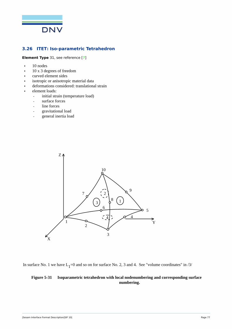
3.26 ITET: Iso-parametric Tetrahedron
Element Type 31, see reference [7]
SESAM INPUT INTERFACE FILEProgram Version Date Page6 01-NOV-1996 5-63
ELTYP=31: Isoparametric Tetrahedron (ITET) /2/ ITET(31)
• 10 nodes• 10 x 3 degrees of freedom• curved element sides• isotropic or anisotropic material data• deformations considered: translational strain• element loads:
- initial strain (temperature load)- surface forces- line forces- gravitational load- general inertia load
In surface No. 1 we have L1=0 and so on for surface No. 2, 3 and 4. See "volume coordinates" in /3/
Figure 5-31 Isoparametric tetrahedron with local nodenumbering and corresponding surfacenumbering.
1
1
2
3
4
X
Z
Y2
3
4
5
9
8
7
10
6
|Sesam Interface Format Description|SIF 10| Page 77

INPUT INTERFACE FILE SESAMPage Date Program Version5-64 01-NOV-1996 6
Figure 5-32 Typical isoparametric tetrahedron with node numbering and numbers defining thevolume coordinates L1, L2, L3, L4.
When surface loads are specified for an element side, the surface numbers shown are used for identification ofthe side in question.
The local nodenumbering for each side is defined as follows:
Node number1 2 3 4 5 6
Side no.1 3 4 5 9 10 82 5 6 1 7 10 93 1 2 3 8 10 74 1 6 5 4 3 2
ITET(31)
1
X
Z
Y2
3
4
5
9
8
7
10
6
L1
L4L3
L3
(1)
(2)
(4)
(4) these numbers define the volume coordinates
|Sesam Interface Format Description|SIF 10| Page 78

SESAM INPUT INTERFACE FILEProgram Version Date Page6 01-NOV-1996 5-65
When line load is specified, the relation between local node numbers and loaded line will be as follows:
Node number1 2 3
Line no.1 1 2 32 3 4 53 5 6 14 1 7 105 3 8 106 5 9 10
Data types for this element:
GELMNT1 *GNODE *GCOORD *GELREF1 *GELINTGELSTRPMISOSEL * orMORSSOL *MTRSOLBEUSLOBEISTEBGRAVBNACCLO
*) Mandatory
ITET(31)
|Sesam Interface Format Description|SIF 10| Page 79

INPUT INTERFACE FILE SESAMPage Date Program Version5-66 01-NOV-1996 6
The following restrictions are put on the data types:
GELINT The integration stations must be distributed according to a scheme similar to the Gaussianintegration scheme, i.e. INTYPE=1. Only the first record of the GELINT specification isused for these element types. The number of integration stations specified for N1 covers thewhole volume of the tetrahedron. N2 will be used to specify the number of integration pointsin the triangular surfaces. The specification of integration points in the triangular surfaces isused in surface load calculations.
N1 must always be specified equal to 5.
Load calculations: Legal values for N2 are 1, 2, 3, 4 and 7. Default value is 4.
GELSTRP The stress points must be distributed according to the same scheme as the integration pointsin the GELINT specification, i.e. STRPTYP=1. Legal values for N1 are 1, 4 and 5. Defaultvalue is 4.
BELLO2 The SIDE-definition is not used. The load components are given nodewise in globalcoordinates.
ITET(31)
Back to Section 3 ELEMENT TYPES
|Sesam Interface Format Description|SIF 10| Page 80

3.27 TPRI: Triangular Prism
Element Type 32, see reference [7]
SESAM INPUT INTERFACE FILEProgram Version Date Page6 01-NOV-1996 5-67
ELTYP=32: Triangular Prism (TPRI), /2/ TPRI(32)
• 6 nodes• 6 x 3 degrees of freedom• linear element sides• isotropic or anisotropic material data• deformation considered: translational displacement• element loads
- initial strain (temperature loads)- volume forces- surface forces- line forces- gravitational load- general acceleration load
Figure 5-33 Triangular prism solid element with local nodenumbering and corresponding surfacenumbering.
4
1
2
y
x
z
2
3
1
4
5
6
3
5
|Sesam Interface Format Description|SIF 10| Page 81

INPUT INTERFACE FILE SESAMPage Date Program Version5-68 01-NOV-1996 6
When surface loads are specified for an element side, the surface numbers shown are used for identification ofthe surface in question.The local nodenumbering for each side is defined as follows:
Node number1 2 3 4
Side no.1 2 3 6 52 3 1 4 63 1 2 5 44 1 2 3 05 6 5 4 0
When line load is specified, the relation between the local node numbers and the loaded line will be as follows:
Node number1 2
Line no.1 1 22 2 33 3 14 1 45 2 56 3 67 4 58 5 69 6 4
Data types used for this element:
GELMNT1 *GNODE *GCOORD *GELREF1 *MISOSEL * orMORSSOL *MTRSOLBELLO2BEUSLOBEISTEBGRAVBNACCLO
*) Mandatory
TPRI(32)
|Sesam Interface Format Description|SIF 10| Page 82

SESAM INPUT INTERFACE FILEProgram Version Date Page6 01-NOV-1996 5-69
The following restrictions are put on data type:
GELINT The integration stations must be distributed according to the Gaussian integration sceme, i.e.INTYPE=1. For this element type the GELINT specifications consist of only the first line. For the triangular plane the integration stations will be specified in the plane and not alonglocal coordinate axis. In the z-direction, integration stations will be distributed according tothe usual Gaussian integration shceme. N1 will be used for specification of number of inte-gration points in the triangular plane, N2 for the number of integration stations in the z-direction.
Stiffness matrix calculation: Legal values for N1 are 3, 4 and 7, for N2, 2, 3 and 4. Defaultvalues are N1=4 and N2=3.
Load calculation: For surface loads N1 will not be used. Number of integration stations inz-direction is given by N2 as before. Legal values of N2 are 2, 3 and 4, with 3 as default. Number of integration stations normal to the z-direction is set equal to one less than N2. This gives a default value equal to 2, and with legal values 1, 2 and 3.
Initial strain: Legal values for N1 are 3, 4 and 7, and for N2, 2, 3 and 4. Default values areN1=4 and N2=3.
Mass matrix calculations: The only legal values for N1 and N2 are N1=4 and N2=3.
GELSTRP The stress points must be distributed according to the Gaussian integration scheme, i.e.STRPTYP=1. Number of stress points in the triangular planes is given by N1. Legal valuesare 1, 3 and 4. The default value of N1 is 1. Number of stress points in the z-direction isspecified by N2. The only legal value of N2 is 2.
BEUSLO An element side may only be loaded once for each BEUSLO-record.
BELLO2 The SIDE definition is not used. The load components are given nodewise in globalcoordinates.
TPRI(32)
Back to Section 3 ELEMENT TYPES
|Sesam Interface Format Description|SIF 10| Page 83

3.28 TETR: Tetrahedron
Element Type 33, see reference [7]
INPUT INTERFACE FILE SESAMPage Date Program Version5-70 01-NOV-1996 6
ELTYP=33: Tetrahedron (TETR), /2/ TETR(33)
• 4 nodes• 4 x 3 degrees of freedom• linear element sides• isotropic or anisotropic material data• deformation considered: translational displacement• element loads
- initial strain (temperature loads)- volume forces- surface forces- line forces- gravitational load- general inertia load
Figure 5-34 Tetrahedron solid element with local node numberieng and corresponding surfacenumbering.
4
3
1
2
y
x
z
4 1
2
3
|Sesam Interface Format Description|SIF 10| Page 84

SESAM INPUT INTERFACE FILEProgram Version Date Page6 01-NOV-1996 5-71
When surface loads are specified for an element side, the surface numbers shown are used for identification ofthe surface in question. The local nodenumbering for each side is defined as follows:
Node number1 2 3
Side no1 3 2 42 1 3 43 2 1 44 1 2 3
When line load is specified, the relation between the local node numbers and the loaded line will be as follows:
Node number1 2
Line no.1 1 22 2 33 3 14 1 45 2 46 3 4
Data types used for this element:
GELMNT1 *GNODE *GCOORD *GELREF1 *MISOSEL * orMORSSOL *BEUSLOBEEO2BEISTEBGRAVBNACCLO
*) Mandatory
TETR(33)
|Sesam Interface Format Description|SIF 10| Page 85

INPUT INTERFACE FILE SESAMPage Date Program Version5-72 01-NOV-1996 6
The following restrictions are put on data type:
GELINT Only the default values for number of integration points are used. This means that if GE-LINT is given, N1 must be specified equal to the default value for the calculation type inquestion:
Stiffness matrix: The centroid of the element is used as the only calculation point.
Load calculation: Constant volume force is only calculated in the centroid of the element. Surface forces in arbitrary direction are calculated in three points on the loaded side, and con-stant normal pressure is calculated in the midpoint on the loaded side.
Initial strain: The centroid of the element is used as the only calculation point.
Mass matrix: Four integration points are used. These are distributed according to the Gauss-ian integration scheme.
GELSTRIP Stresses are only calculated in the centroid of the element. If the GELSTRP specification isgiven, only the first record is used. This must be given with STRPTYP=1 and N1=1. N2should not be specified.
BEUSLO Only one side can be loaded in each load case. This means that only one side identificationcan be given in SIDE. The element can only reproduce a constant strain situation. Variationin loads will cause a stress situation which the element is not able to reproduce. Thereforethis element should only be used for constant loads, i.e. the load intensity should be the samefor all the nodes on the loaded side.
BELLO2 The SIDE definition is not used. The load components are given nodewise in global coordi-nates.
TETR(33)
Back to Section 3 ELEMENT TYPES
|Sesam Interface Format Description|SIF 10| Page 86

3.29 LCTS: Sub-parametric Layered Curved Triangular Shell
Element Type 34
SESAM INPUT INTERFACE FILEProgram Version Date Page6 01-NOV-1996 5-73
ELTYP=34: Subparametric Layered Curved LCTS(34)Triangular Shell (LCTS), for Ref. See SCTS /2/
• 6 nodes• 6 x 6 degrees of freedom• curved element shape• isotropic or anisotropic material data (anisotropic only, in ’plate layers’)• one or more material layers• the layers may be eccentric plate layers and / or eccentric stiffener layers with bar stiffeners in one arbi-
trary direction. Each layer may have different stiffener direction• deformations considered:
bending, shear and translational strain• constant element thickness• element loads:
- initial strain- surface forces- line loads- line moment load- gravitational load- general inertia load
Figure 5-35 Element local node numbering. Three layers - one plate layer and two stiffener layers.
The stiffeners are transformed to layers with no stiffness in the direction lateral to the stiffener direction, andsmeared stiffness in the stiffener direction. The direction defining the local element coordinate axes (local x-,
1
local element z-dirction
eccentricitiesin neg. local z-direction
1st layer - plate
2nd layer - eccentric stiffener
3rd layer - eccentric stiffener
’spacing’ = ’field width’ / ’no. of stiffeners’
’field width’
36
2
5
local element node nos.
|Sesam Interface Format Description|SIF 10| Page 87

INPUT INTERFACE FILE SESAMPage Date Program Version5-74 01-NOV-1996 6
y- and z-axes) are specified on a BNTRCOS record for this element. Only the x-direction (first line) in thedirection cosine matrix defined on the BNTRCOS record is used.
The projection of this vector onto the middle of the element surface defines the local x-axis in different pointson the element. The positive local z-direction, normal to the element middlesurface, is chosen according to thenormal convention of the right hand rule, i.e. the positive z-direction is found when the local element nodenumbers are followed in ascending order. The BNTRCOS record is referred on the GELREF1 record.
The material may be general anisotropic in the plate layer(s) of the element, but if stiffener layers are specified,they must have isotropic material. For anisotropic materials, each layer must have a separate anisotropic mate-rial specification (MORSSEL record).
Figure 5-36 Element local node numbering and local normalised coordinate system.
When line load is specified, the relation between local node numbers and loaded line will go:
LINE=1 means line load on the element side defined by nodes 2, 5 and 3LINE=2 means line load on the element side defined by nodes 1, 6 and 3LINE=3 means line load on the element side defined by nodes 1, 4 and 2
LCTS(34)
ζ
ζ= 1
ζ= -1L1L3
L2
1
2
3
4
5
6
|Sesam Interface Format Description|SIF 10| Page 88

SESAM INPUT INTERFACE FILEProgram Version Date Page6 01-NOV-1996 5-75
The orientation of the local normalised coordinate system is related to the local node numbering sequence (seeFigure 5-36). The positive ζ-direction, normal to the element middlesurface, is chosen according to the normalconvention of the right hand rule, i.e. the positive ζ-direction is found when the node numbers are followed inascending order.
The SIDE definition on the BEUSLO records is as follows:
SIDE=1 means that load is given on the element surface where ζ= -1,SIDE=2 that ζ= 0 is loaded, andSIDE=3 that ζ= 1 is loaded.
LCTS(34)
|Sesam Interface Format Description|SIF 10| Page 89
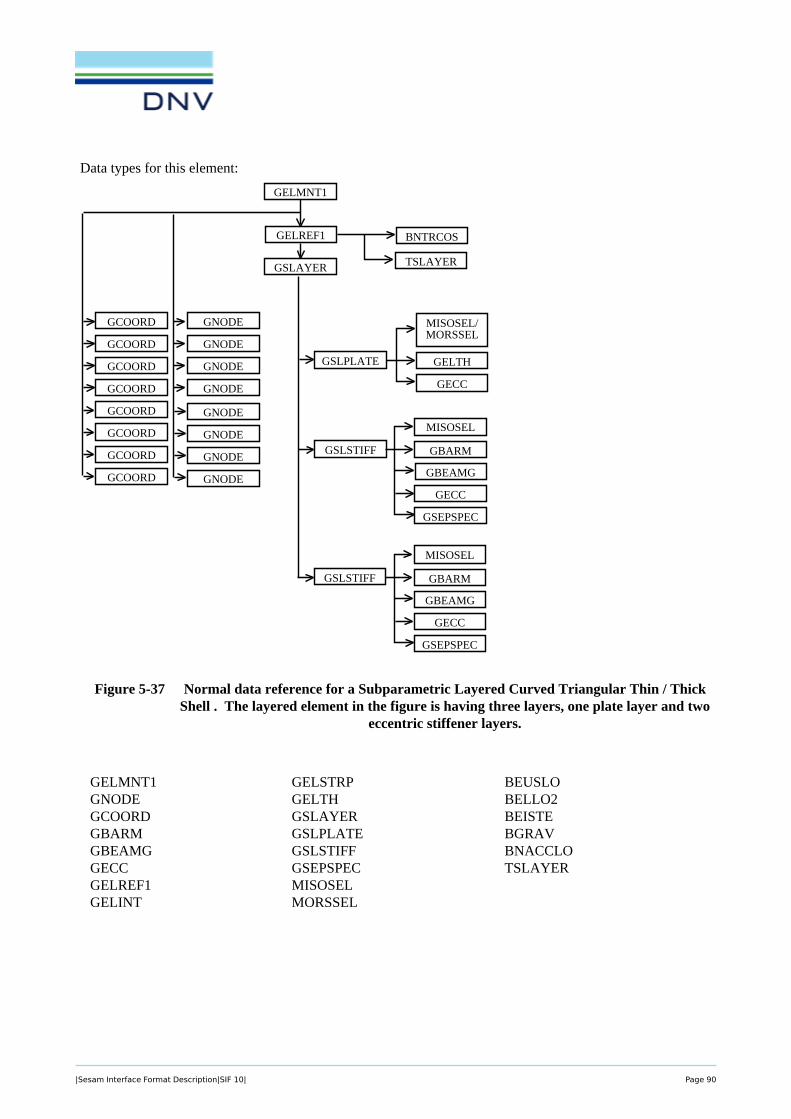
INPUT INTERFACE FILE SESAMPage Date Program Version5-76 01-NOV-1996 6
Data types for this element:
Figure 5-37 Normal data reference for a Subparametric Layered Curved Triangular Thin / ThickShell . The layered element in the figure is having three layers, one plate layer and two
eccentric stiffener layers.
LCTS(34)
GSLPLATE
GELMNT1
GNODEGCOORD
GCOORD
GCOORD
GCOORD
GNODE
GNODE
GNODE
GSLAYER
GELREF1 BNTRCOS
GNODE
GNODE
GNODE
GNODE
GCOORD
GCOORD
GCOORD
GCOORD
MISOSEL/MORSSEL
GELTH
GECC
TSLAYER
GSLSTIFF
MISOSEL
GBARM
GECC
GSEPSPEC
GBEAMG
GSLSTIFF
MISOSEL
GBARM
GECC
GSEPSPEC
GBEAMG
GELMNT1GNODEGCOORDGBARMGBEAMGGECCGELREF1GELINT
GELSTRPGELTHGSLAYERGSLPLATEGSLSTIFFGSEPSPECMISOSELMORSSEL
BEUSLOBELLO2BEISTEBGRAVBNACCLOTSLAYER
|Sesam Interface Format Description|SIF 10| Page 90

SESAM INPUT INTERFACE FILEProgram Version Date Page6 01-NOV-1996 5-77
The following restrictions are put on the data types.
GELINT The integration stations must be distributed according to a scheme similar to the Gaussianintegration scheme, i.e. INTYPE=1. For this element type the GELINT specifications consistof the first line only. The integration stations will be specified in the triangle planes, and notalong local coordinate axes. The value specified for N1 is not the number of integration sta-tions but a reference number to specified distributions of integration stations, which mayhave the same number of integration stations, but different positions in the triangle planes. Therefore, N3 has no meaning for this element type. Legal values for N1 are 1, 2, 3, 4, 5, 6,7, 8, 9, see description of subroutine HAMC30 in the finite element library, /2/. N2 ("ζ-direction") is not possible to specify and the value 2 is used for each layer. The integration inζ-direction will be performed analytically if max deviation from mean thickness is 5% andthe element is nearly flat.
Stiffness matrix: Default value for N1 is 7.
Load calculations: Default value for N1 is 6 for surface loads.
Initial strain: Default value for N1 is 6.
Mass matrix: N1 should be specified ³ 7 to ensure positive definite mass matrix. Defaultvalue is N1=7.
GELSTRP The stress points must be distributed according to the same scheme as the integration pointsin the GELINT specification, for stress point coordinates in the triangular plane. The stresspoint coordinates in the ζ-direction are distributed according to the usual Gaussian integra-tion scheme STRPTYP=1. Legal values for N1 are 1, 3, 4, 7, 9, and for N2 2, 3, 4.Default values for N1 is 3 and for N2 ("z-direction") the default value is 2.Only the first record of the GELSTRP specification is used for this element type.
BELLO2 The SIDE-definition is not used.
LCTS(34)
Back to Section 3 ELEMENT TYPES
|Sesam Interface Format Description|SIF 10| Page 91

3.30 LCQS: Sub-parametric Layered Curved Quadrilateral Shell
Element Type 35
INPUT INTERFACE FILE SESAMPage Date Program Version5-78 01-NOV-1996 6
ELTYP=35: Subparametric Layered Curved LCQS(35)Quadrilateral Shell (LCQS), for Ref. See SCQS /2/
• 8 nodes• 8 x 6 degrees of freedom• curved element shape• isotropic or anisotropic material data (anisotropic only, in ’plate layers’)• one or more material layers• the layers may be eccentric plate layers and / or eccentric stiffener layers with bar stiffeners in one arbi-
trary direction. Each layer may have different stiffener direction• deformations considered:
bending, shear and translational strain• constant element thickness• element loads:
- initial strain- surface forces- line loads- line moment load- gravitational load- general inertia load
Figure 5-38 Element local node numbering. Three layers - one plate layer and two stiffener layers.
The stiffeners are transformed to layers with no stiffness in the direction lateral to the stiffener direction, andsmeared stiffness in the stiffener direction. The direction defining the local element coordinate axes (local x-,y- and z-axes) are specified on a BNTRCOS record for this element. Only the x-direction (first line) in thedirection cosine matrix defined on the BNTRCOS record is used.
1
local element z-dirction
eccentricitiesin neg. local z-direction
1st layer - plate
2nd layer - eccentric stiffener
3rd layer - eccentric stiffener
’spacing’ = ’field width’ / ’no. of stiffeners’
’field width’
78
5
6
local element node nos.
|Sesam Interface Format Description|SIF 10| Page 92

SESAM INPUT INTERFACE FILEProgram Version Date Page6 01-NOV-1996 5-79
The projection of this vector onto the middle of the element surface defines the local x-axis in different pointson the element. The positive local z-direction, normal to the element middlesurface, is chosen according to thenormal convention of the right hand rule, i.e. the positive z-direction is found when the local element nodenumbers are followed in ascending order. The BNTRCOS record is referred on the GELREF1 record.
The material may be general anisotropic in the plate layer(s) of the element, but if stiffener layers are specified,they must have isotropic material. For anisotropic materials, each layer must have a separate anisotropic mate-rial specification (MORSSEL record).
Figure 5-39 Element local node numbering and local normalised coordinate system.
When line load is specified, the relation between local node numbers and loaded line will go:
LINE=1 means line load along the line defined by the nodes 3, 4 and 5LINE=2 means line load along the line defined by the nodes 2 and 6LINE=3 means line load along the line defined by the nodes 1, 8 and 7LINE=4 means line load along the line defined by the nodes 7, 6 and 5LINE=5 means line load along the line defined by the nodes 8 and 4LINE=6 means line load along the line defined by the nodes 1, 2 and 3
LCQS(35)
ξη
ζ
2
3
4
5
6
7
8
1
ξη
ζ
η= 1
ξ= 1
ξ= -1
ζ= 1
ζ= -1
η= -1
|Sesam Interface Format Description|SIF 10| Page 93

INPUT INTERFACE FILE SESAMPage Date Program Version5-80 01-NOV-1996 6
The orientation of the local normalised coordinate system is related to the local node numbering sequence (seeFigure 5-39). The positive ζ-direction, normal to the element middlesurface, is chosen according to the normalconvention of the right hand rule, i.e. the positive ζ-direction is found when the node numbers are followed inascending order.
The SIDE definition on the BEUSLO records is as follows:
SIDE=1 means that load is given on the element surface where ζ= -1,SIDE=2 that ζ= 0 is loaded, andSIDE=3 that ζ= 1 is loaded.
LCQS(35)
|Sesam Interface Format Description|SIF 10| Page 94

SESAM INPUT INTERFACE FILEProgram Version Date Page6 01-NOV-1996 5-81
Data types for this element:
Figure 5-40 Normal data reference for a Subparametric Layered Curved Quadrilateral Thin / ThickShell . The layered element in the figure is having three layers, one plate layer and two
eccentric stiffener layers.
LCQS(35)
GSLPLATE
GELMNT1
GNODEGCOORD
GCOORD
GCOORD
GCOORD
GNODE
GNODE
GNODE
GSLAYER
GELREF1 BNTRCOS
GNODE
GNODE
GNODE
GNODE
GCOORD
GCOORD
GCOORD
GCOORD
MISOSEL/MORSSEL
GELTH
GECC
TSLAYER
GSLSTIFF
MISOSEL
GBARM
GECC
GSEPSPEC
GBEAMG
GSLSTIFF
MISOSEL
GBARM
GECC
GSEPSPEC
GBEAMG
GELMNT1GNODEGCOORDGBARMGBEAMGGECCGELREF1GELINT
GELSTRPGELTHGSLAYERGSLPLATEGSLSTIFFGSEPSPECMISOSELMORSSEL
BEUSLOBELLO2BEISTEBGRAVBNACCLOTSLAYER
|Sesam Interface Format Description|SIF 10| Page 95

INPUT INTERFACE FILE SESAMPage Date Program Version5-82 01-NOV-1996 6
The following restrictions are put on the data types.
GELINT The integration stations must be distributed according to the Gaussian integration scheme,i.e. INTYPE=1. For this element type only the first line of the GELINT specifications isused. N3 ("ζ-direction") is not possible to specify and the value 2 is used for each layer. Theintegration in ζ-direction will be performed analytically if max deviation from mean thick-ness is 5% and the element is nearly flat.
Stiffness matrix: Legal values for N1 and N2 are 2 and 3.Default value is 2 for both.
Load calculations: Legal values for N1 and N2 are 2, 3 and 4.Default value is 2 for both.
Initial strain: Legal values for N1 and N2 are 2 and 3.Default value is 2 for both.
Mass matrix: Legal values for N1 and N2 are 1, 2, 3 and 4. To ensure positive definite massmatrix N1=N2=4 is recommended.Default value is N1=N2=4.
GELSTRP The stress points must be distributed according to the Gaussian integration scheme, i.e.STRPTYP=1. The only legal value for N1 and N2 is 2. N3 may be 2, 3 or 4. This gives4*N3 stress points within each layer of the element.
BELLO2 The SIDE-definition is not used.
LCQS(35)
Back to Section 3 ELEMENT TYPES
|Sesam Interface Format Description|SIF 10| Page 96

3.31 TRSI: Transition Elements between Solids and Shells
Element Type 36, 37, or 38, see reference [3]
SESAM INPUT INTERFACE FILEProgram Version Date Page6 01-NOV-1996 5-83
ELTYP=36, 37 or 38: Transition Elements between TRSI(36, 37, 38)Solids and Shells (TRSI), /6/
• 18, 15 or 12 nodes• 57, 54 or 51 degrees of freedom• curved or linear element sides• parabolically varying element thickness (in relevant nodes of ELTYP=37 and 38 only)• isotropic or anisotropic material data• deformations considered: translational strain• element loads:
- initial strain (temperature loads)- surface forces- line forces- gravitational load- general inertia load
The TRSI elements are described in detail in /6/
Figure 5-41 Local node numbering and corresponding surface numbering for transition element withone "shell type node", the "shell type node" is node number 9.
ζ
ξ
η
1
2
3 4
6
5
1
2
34
5
67
8
910
11
12
13
1415
16
1718
solid type nodesshell type nodes
ELTYP=36:1 shell type node17 solid type nodes57 degrees of freedom
|Sesam Interface Format Description|SIF 10| Page 97

INPUT INTERFACE FILE SESAMPage Date Program Version5-84 01-NOV-1996 6
Figure 5-42 Local node numbering and corresponding surface numbering for transition element withthree "shell type nodes", the "shell type nodes" is node number 7, 8 and 9.
Figure 5-43 Local node numbering and corresponding surface numbering for transition element withfive "shell type nodes", the "shell type nodes" are nodes number 5 through 9.
TRSI(36, 37, 38)
1
2
3 4
6
5
1
24
5
6
79
10
11
12
15
solid type nodesshell type nodes
ELTYP=37:3 shell type node12 solid type nodes54 degrees of freedom
8
3
13
14
ζ
ξ
η
1
2
3 4
6
5
1
2
83
4
57
9
11
12
15
solid type nodesshell type nodes
ELTYP=38:5 shell type node7 solid type nodes51 degrees of freedom
6
ζ
ξ
η
|Sesam Interface Format Description|SIF 10| Page 98

SESAM INPUT INTERFACE FILEProgram Version Date Page6 01-NOV-1996 5-85
Loads on the element are specified as if given for an IHEX element (ELTYP=20) (the so-called originatingIHEX element) with that element’s number of nodes, type of nodes (3 translational degrees of freedom) andsequence of nodes specifying the originating element. (see the tables and figures below for TRSI(36), TRSI(37)and TRSI(38)).When surface load is specified for one element side, the load intensities are always given in eigth points oneach side, regardless of this beeing a "solid side" or a "shell side". These points are the nodes on the "solidsides", and the points on the upper and lower element side corresponding to the nodes on the "shell sides". Thepoints on the upper and lower shell element side is marked with the same number as the node in the ’shellmiddle plane’ with a ’ (prime) and " (double prime) to separate them from the ’real nodes’.
With correspondence to Figure 5-41, 5-42 and 5-43 the local node ("point") numbering of each side is definedas follows:
TRSI(36, 37, 38)
|Sesam Interface Format Description|SIF 10| Page 99

INPUT INTERFACE FILE SESAMPage Date Program Version5-86 01-NOV-1996 6
It should be noted that the points in the three tables and Figs. 5-41, 5-42 and 5-43 below are in the same topo-logical positions on the sides, but the node (point) numbers are different, since number of ’real nodes’ are dif-ferent. The point numbers are sort of dummy numbers and only used to indicate the sequence of the load inten-sities to be specified.
TRSI(36)
Local node ("point") number on side1 2 3 4 5 6 7 8
Side no.1 6 7 1 8 12 18 17 112 4 10 15 14 9" 9 9’ 33 1 2 9’ 9 9" 13 12 84 6 11 17 16 15 10 4 55 6 5 4 3 9’ 2 1 76 17 18 12 13 9" 14 15 16
Figure 5-44 Numbering of nodes (points) where surface and line load values are specified forTRSI(36)-elements
TRSI(36, 37, 38)
1
2
3 4
6
5
1
2
34
5
67
8
9
10
11
12
13
1415
16
1718
9’
9"
solid type nodesshell type nodegeometric points+ζ
ξ
η
|Sesam Interface Format Description|SIF 10| Page 100

SESAM INPUT INTERFACE FILEProgram Version Date Page6 01-NOV-1996 5-87
TRSI(37)
Local node ("point") number on side1 2 3 4 5 6 7 8
Side no.1 4 5 1 6 11 15 14 102 9’ 9 9" 8" 7" 7 7’ 8’3 1 2 7’ 7 7" 12 11 64 4 10 14 13 9" 9 9’ 35 4 3 9’ 8’ 7’ 2 1 56 14 15 11 12 7" 8" 9" 13
Figure 5-45 Numbering of nodes (points) where surface and line load values are specified forTRSI(37)-elements
TRSI(36, 37, 38)
1
2
3 4
6
5
1
24
5
6
7 9
10
11
12
15
solid type nodesshell type nodes
8
3
13
14
9’
9"
8’
8"
7’
7"
geometric points+ζ
ξ
η
|Sesam Interface Format Description|SIF 10| Page 101

INPUT INTERFACE FILE SESAMPage Date Program Version5-88 01-NOV-1996 6
TRSI(38)
Local node ("point") number on side1 2 3 4 5 6 7 8
Side no.1 9’ 3 1 4 10 12 9" 92 7’ 7 7" 6" 5" 5 5’ 6’3 1 2 5’ 5 5" 11 10 44 9’ 9 9" 8" 7" 7 7’ 8’5 9’ 8’ 7’ 6’ 5’ 2 1 36 9" 12 10 11 5" 6" 7" 8"
Figure 5-46 Numbering of nodes (points) where surface and line load values are specified forTRSI(37)-elements
TRSI(36, 37, 38)
1
2
3 4
6
5
1
2
83
4
57
9
10
11
12
solid type nodesshell type nodes
6
8’
9’
9"
8"
7’
7"
5’
5"
6’
6"
geometric points+ζ
ξ
η
|Sesam Interface Format Description|SIF 10| Page 102

SESAM INPUT INTERFACE FILEProgram Version Date Page6 01-NOV-1996 5-89
Line loads are specified in the same manner as surface loads. The load intenisties are always given in pointsalong lines as defined for the IHEX-element (the so-called originating IHEX element). In the table below thenumbers without prime and double prime refer to the node numbers of the actual TRSI element. The the nm-bers with prime or double prime refers to the geometrical point below or above the TRSI node. With refer-rence to Figs. 5-41, 5-42 and 5-43 the local node (point) numbering for each line is defined as follows:
TRSI(36) TRSI(37) TRSI(38)
Local node ("point") number on line:
1 2 3 1 2 3 1 2 3Line no.:
1 1 2 9’ 1 2 7’ 1 2 5’2 9’ 3 4 7’ 8’ 9’ 5’ 6’ 7’3 4 5 6 9’ 3 4 7’ 8’ 9’4 6 7 1 4 5 1 9’ 3 1
5 1 8 12 1 6 11 1 4 106 9’ 9 9" 7’ 7 7" 5’ 5 5"7 4 10 15 9’ 9 9" 7’ 7 7"8 6 11 17 4 10 14 9’ 9 9"
9 12 13 9" 11 12 7" 10 11 5"10 9" 14 15 7" 8" 9" 5" 6" 7"11 15 16 17 9" 13 14 7" 8" 9"12 17 18 12 14 15 11 9" 12 10
13 7 3 5 8’ 3 6’14 5 2 3 2 8’ 215 8 9 6 7 4 516 2 13 2 12 2 11
17 9 7 7 9 5 718 3 14 8’ 8" 6’ 6"19 10 11 9 10 7 920 5 16 3 13 8’ 8"
21 11 8 10 6 9 422 7 18 5 15 3 1223 18 14 15 8" 12 6"24 13 16 12 13 11 8"
TRSI(36, 37, 38)
|Sesam Interface Format Description|SIF 10| Page 103

INPUT INTERFACE FILE SESAMPage Date Program Version5-90 01-NOV-1996 6
Data types used for this element:
GELMNT1 *GNODE *GCOORD *GELREF1 *GELTH *GELINTGELSTRPMISOSEL * orMISOPL * orMORSSOL *MTRSOLBEUSLOBELLO2BEISTEBGRAVBNACCLO
*) Mandatory
TRSI(36, 37, 38)
|Sesam Interface Format Description|SIF 10| Page 104

SESAM INPUT INTERFACE FILEProgram Version Date Page6 01-NOV-1996 5-91
Restrictions on modelling with transition elements:
The "shell type nodes" have no stiffness connected to the rotational degree of freedom perpendicular to themiddle plane. In shell elements this is taken care of by inserting a small stiffness value to avoid a rectangularsystem. Hence the "shell type nodes" of the transition elements must always be coupled to a shell element inorder to avoid a singular stiffness matrix.
Restrictions on data types:
GELREF1 Parameters INTNO, MINTNO, STRANO, STRENO and STREPONO all refer to datagroups were the data are specified as if given for an IHEX element (ELTYP=20). The ele-ment thickness of the shell type node(s) must be referred to, either directly by GEONO/OPTor indirectly by GEONO(i) (with GEONO/OPT=-1). In the latter case the GEONO(i) forsolid type numbers are of no consequence (set equal to zero).
GELINT The data is as if given for an IHEX element (ELTYP=20). When giving nodal values GELSTRP (intensities) they shall refer to a so-called originating IHEX element. See Figure 5-41 BEUSLO above.BEISTE
GNODE The values of NDOF and ODOF must be consistent with the type of node:solid type: NDOF=3, ODOF=123shell type: NDOF=6, ODOF=123456
• 2 nodes• degrees of freedom, arbitrary (max 12)• stiffness matrix
Data types used for this element:
GELMNT1 *GELREF1 *MSHGLSP *BNTRCOS
*) Mandatory
TRSI(36, 37, 38)
Back to Section 3 ELEMENT TYPES
|Sesam Interface Format Description|SIF 10| Page 105

3.32 GLSH: General 2-Noded Spring / Shim Element
Element Type 40
INPUT INTERFACE FILE SESAMPage Date Program Version5-92 01-NOV-1996 6
LTYP=40: General 2-Noded Spring / Shim Element (GLSH) GLSH(40)
• 2 nodes• degrees of freedom, arbitrary• general spring matrix
Figure 5-47 General 2-noded spring element
As General Spring it is just a 2-noded spring (12x12 matrix) which may be in a local coordinate system. As ashim element the preprocessor(s) will only insert stiffness in the local x- and y-direction. In the analysis pro-gram(s), shim members and general springs are treated exactly in the same manner.
The resulting spring matrix is a full symmetric matrix where all values on and below the main diagonal arestored.
Data types used for this element:
GELMNT1 *MSHGLSP * (NDOF1 and NDOF2 must be equal to NDOF on data type GNODE for node "1" and node"2")GELREF1 *BNTRCOS (Transformation in the two nodes may be different. But NDOF1 = NDOF2 = 3 or 6 is requiredfor transformation).
*) Mandatory
node "1"
node "2"
Back to Section 3 ELEMENT TYPES
|Sesam Interface Format Description|SIF 10| Page 106

3.33 AXCS: Axi-symmetric Constant Strain Triangle
Element Type 41
SESAM INPUT INTERFACE FILEProgram Version Date Page6 01-NOV-1996 5-93
ELTYP=41: Axisymmetric Constant Strain Triangle AXCS(41)(AXCS), for Ref. See CSTA in /2/
• 3 nodes• 3 x 3 degrees of freedom• straight
- line loads- initial strain (temperature load)- gravitational load (only in the membrane plane)- general inertia load (only in the membrane plane)
• isotropic or anisotropic material data
Local node numbering:
Figure 5-48 Element node numbering. Global cylindrical coordinate system.
When line load is specified, the relation between local node numbers and loaded line will be:
Line 1 means load along the line defined by the nodes 2 and 3.Line 2 means load along the line defined by the nodes 1 and 3Line 3 means load along the line defined by the nodes 1 and 2.
The direction of node numbering must be counterclockwise.
v2
Z, v
R, u
u22
1
3
u3
v1
u1
Global cylindrical coordinates
v3
|Sesam Interface Format Description|SIF 10| Page 107

INPUT INTERFACE FILE SESAMPage Date Program Version5-94 01-NOV-1996 6
Data types used for this element:
GELMNT1 *GELREF1 *GNODE *GCOORD *
MISOSEL * orMORSMEL *MTRMEL
BELLAXBEISTEBGRAVBNACCLO
*) Mandatory
AXCS(41)
Back to Section 3 ELEMENT TYPES
|Sesam Interface Format Description|SIF 10| Page 108

3.34 AXLQ: Axi-symmetric Constant Strain Quadrilateral
Element Type 42
SESAM INPUT INTERFACE FILEProgram Version Date Page6 01-NOV-1996 5-95
ELTYP=42: AXLQ(42)(AXLQ), for ref. see LQUA in /2/
• 4 nodes• 4 x 3 degrees of freedom• straight• element loads
- line loads- initial strain (temperature load)- gavitational load (only in the membrane plane)- general inertia load (only in the membrane plane)
• isotropic or anisotropic material data• deformations considered: translational strain
Local node numbering:
Figure 5-49 Element node numbering. Global cylindrical coordinate system.
When line load is specified, the relation between local node numbers and loaded line will be:
LINE 1 means load along the line defined by the nodes 1 and 2LINE 2 means load along the line defined by the nodes 2 and 3LINE 3 means load along the line defined by the nodes 3 and 4LINE 4 means load along the line defined by the nodes 4 and 1
The direction of node numbering must be counterclockwise.
v
Z, v
R, u
1
Global cylindrical coordinates
4
2
3
u
|Sesam Interface Format Description|SIF 10| Page 109

INPUT INTERFACE FILE SESAMPage Date Program Version5-96 01-NOV-1996 6
Data types used for this element:
GELMNT1 *GELREF1 *GNODE *GCOORD *GELINT
MISOSEL or *MORSMELMTRMEL
BELLAXBEISTEBGRAVBNACCLO
*) Mandatory
The following restrictions are put on data types:
GELINT The integration stations must be distributed according to the Gaussian integration scheme,i.e.INTYPE =1. For this element type the GELINT specifications consist of the first line.
Stiffness matrix:Legal values for N1 and N2 are 2 and 3. N1 and N2 must have the same value.Default value is N1=N2=2.
Mass matrix: For mass matrix calculations the number of integration stations will be thesamein both coordinate directions and equal to the value specified for N1 for the stiffness matrix.
AXLQ(42)
Back to Section 3 ELEMENT TYPES
|Sesam Interface Format Description|SIF 10| Page 110
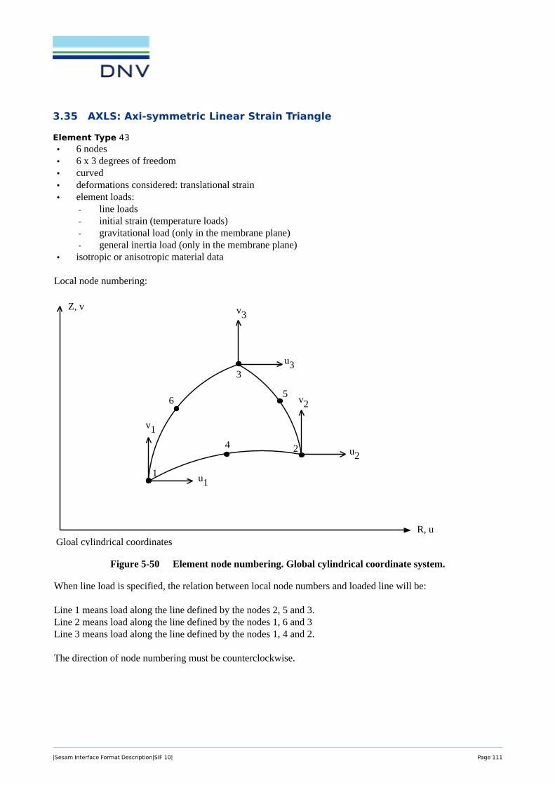
3.35 AXLS: Axi-symmetric Linear Strain Triangle
Element Type 43
SESAM INPUT INTERFACE FILEProgram Version Date Page6 01-NOV-1996 5-97
ELTYP=43: Axisymmetric Linear Strain Triangle AXLS(43)(AXLS), for Ref. see ILST in /2/
• 6 nodes• 6 x 3 degrees of freedom• curved• deformations considered: translational strain• element loads:
- line loads- initial strain (temperature loads)- gravitational load (only in the membrane plane)- general inertia load (only in the membrane plane)
• isotropic or anisotropic material data
Local node numbering:
Figure 5-50 Element node numbering. Global cylindrical coordinate system.
When line load is specified, the relation between local node numbers and loaded line will be:
Line 1 means load along the line defined by the nodes 2, 5 and 3.Line 2 means load along the line defined by the nodes 1, 6 and 3Line 3 means load along the line defined by the nodes 1, 4 and 2.
The direction of node numbering must be counterclockwise.
v2
Z, v
R, u
u22
1
3
v3
u3
v1
u1
Gloal cylindrical coordinates
56
4
|Sesam Interface Format Description|SIF 10| Page 111

INPUT INTERFACE FILE SESAMPage Date Program Version5-98 01-NOV-1996 6
The following restrictions are put on the data types
GELINT The integration stations must be distributed according to the Gaussian integration scheme,i.e.INTYPE =1. For this element type the GELINT specifications consist of the first filerecord(line) only.
Stiffness matrix: For stiffness matrix calculations the number of integration stations will be equal to the value specified for N1.Legal values are 1, 3, 4 and 7.Default value is 4.
Mass matrix: Only possible value and default value is 7.
Load vector: Only possible value and default value is 3.
Data types used for this element:
GELMNT1 *GELREF1 *GNODE *GCOORD *GELINT
MISOSEL or *MORSMELMTRMEL
BELLAXBEISTEBGRAVBNACCLO
*) Mandatory
AXLS(43)
Back to Section 3 ELEMENT TYPES
|Sesam Interface Format Description|SIF 10| Page 112

3.36 AXQQ: Axi-symmetric Linear Strain Quadrilateral
Element Type 44
SESAM INPUT INTERFACE FILEProgram Version Date Page6 01-NOV-1996 5-99
ELTYP=44: Axisymmetric Linear Strain Quadrilateral AXQQ(44) (AXQQ), for Ref. see IQQE in /2/
• 8 nodes• 8 x 3 degrees of freedom• curved• deformations considered: translational strain• element loads:
- line loads- initial strain (temperature loads)- gravitational load (only in the membrane plane)- general inertia load (only in the membrane plane)
• isotropic or anisotropic material data
Local node numbering:
Figure 5-51 Element node numbering. Global cylindrical coordinate system.
When line load is specified, the relation between local node numbers and loaded line will be:
LINE 1 means load along the line defined by the nodes 2, 6 and 3LINE 2 means load along the line defined by the nodes 5 and 7LINE 3 means load along the line defined by the nodes 1, 8 and 4LINE 4 means load along the line defined by the nodes 1, 5 and 2LINE 5 means load along the line defined by the nodes 8 and 6LINE 6 means load along the line defined by the nodes 4, 7 and 3
v
Z, v
R, u
1
Gloal cylindrical coordinates
4
2
5
3
8u
7
6
|Sesam Interface Format Description|SIF 10| Page 113

INPUT INTERFACE FILE SESAMPage Date Program Version5-100 01-NOV-1996 6
The direction of node numbering must be counterclockwise.
The following restrictions are put on the data types
GELINT The integration stations must be distributed according to the Gaussian integration scheme,i.e.INTYPE =1. For this element type the GELINT specifications consist of the first filerecord only.
Stiffness matrix: For stiffness matrix calculations the number of integration stations will be the same in both coordinate directions and equal to the value specified for N1.Legal values are 2 and 3. Default value is 3.
Mass matrix: For mass matrix calculations the number of integration stations will be the same in both coordinate directions and equal to the value specified for N1 for the stiffnessmartix..
Load vector: 3 is used, the variable is not possible to specify for the user.
BELLO2 LINE = 2 and LINE = 5 is not operative in SESTRA.
Data types used for this element:
GELMNT1 *GELREF1 *GNODE *GCOORD *GELINT
MISOSEL or *MORSMELMTRMEL
BELLAXBELLO2BEISTEBGRAVBNACCLO
*) Mandatory
AXQQ(44)
Back to Section 3 ELEMENT TYPES
|Sesam Interface Format Description|SIF 10| Page 114

3.37 CTCP: 2-Noded (1+1) Contact Element
Element Type 51
SESAM INPUT INTERFACE FILEProgram Version Date Page6 01-NOV-1996 5-101
ELTYP=51: 2 noded (1+1) Contact Element CTCP(51)
• 2 nodes• 2 x 6 degrees of freedom• contact material (see the MCNT record)• deformations considered:
separation and relative tangential desplacement between surfaces.• zero thickness.• element loads:
- none
Figure 5-52 Element node numbering.
nt
2
1
z
x
y
|Sesam Interface Format Description|SIF 10| Page 115

INPUT INTERFACE FILE SESAMPage Date Program Version5-102 01-NOV-1996 6
Data types for this element:
GELMNT1 *GNODE *GCOORD *GELREF1 *GELTH **GELINTMCNT *
*) Mandatory**) If the nodes in the two layers (sides) of the element in the model do not coincide, thickness of the elementmay be specified by GELTH records.Any distance between the two layers (sides) which is different from specified thickness is interpreted as initialgap or initial penetration of the contact surface.
CTCP(51)
Back to Section 3 ELEMENT TYPES
|Sesam Interface Format Description|SIF 10| Page 116

3.38 CTCL: 4-Noded (2+2) Contact Element
Element Type 52
SESAM INPUT INTERFACE FILEProgram Version Date Page6 01-NOV-1996 5-103
ELTYP=52: 4 noded (2+2) Contact Element CTCL(52)
• 4 nodes• 4 x 6 degrees of freedom• linear element shape• contact material (see the MCNT record)• deformations considered:
separation and relative tangential desplacement between surfaces.• zero thickness.• element loads:
- none
Figure 5-53 Element node numbering.
nt
4
3
2
1
z
x
y
|Sesam Interface Format Description|SIF 10| Page 117

INPUT INTERFACE FILE SESAMPage Date Program Version5-104 01-NOV-1996 6
Data types for this element:
GELMNT1 *GNODE *GCOORD *GELREF1 *GELTH **GELINTMCNT *
*) Mandatory**) If the nodes in the two layers (sides) of the element in the model do not coincide, thickness of the elementmay be specified by GELTH records.Any distance between the two layers (sides) which is different from specified thickness is interpreted as initialgap or initial penetration of the contact surface.
CTCL(52)
Back to Section 3 ELEMENT TYPES
|Sesam Interface Format Description|SIF 10| Page 118

3.39 CTAL: 4-Noded (2+2) Axi-symmetric Contact Element
Element Type 53
SESAM INPUT INTERFACE FILEProgram Version Date Page6 01-NOV-1996 5-105
ELTYP=53: 4 noded (2+2) Axisymmetric Contact Element CTAL(53)
• 4 nodes• 4 x 3 degrees of freedom• linear element shape• contact material (see the MCNT record)• deformations considered:
separation and relative tangential desplacement between surfaces.• zero thickness.• element loads:
- none
Figure 5-54 Element node numbering.
nt
4
3
2
1
R
Z
|Sesam Interface Format Description|SIF 10| Page 119

INPUT INTERFACE FILE SESAMPage Date Program Version5-106 01-NOV-1996 6
Data types for this element:
GELMNT1 *GNODE *GCOORD *GELREF1 *GELTH **GELINTMCNT *
*) Mandatory**) If the nodes in the two layers (sides) of the element in the model do not coincide, thickness of the elementmay be specified by GELTH records.Any distance between the two layers (sides) which is different from specified thickness is interpreted as initialgap or initial penetration of the contact surface.
CTAL(53)
Back to Section 3 ELEMENT TYPES
|Sesam Interface Format Description|SIF 10| Page 120

3.40 CTCC: 6-Noded (3+3) Contact Element
Element Type 54
SESAM INPUT INTERFACE FILEProgram Version Date Page6 01-NOV-1996 5-107
ELTYP=54: 6 noded (3+3) Contact Element CTCC(54)
• 6 nodes• 6 x 6 degrees of freedom• curved element shape• contact material (see the MCNT record)• deformations considered:
separation and relative tangential desplacement between surfaces.• zero thickness.• element loads:
- none
Figure 5-55 Element node numbering.
nt
6
5
4
2
3
1
z
x
y
|Sesam Interface Format Description|SIF 10| Page 121

INPUT INTERFACE FILE SESAMPage Date Program Version5-108 01-NOV-1996 6
Data types for this element:
GELMNT1 *GNODE *GCOORD *GELREF1 *GELTH **GELINTMCNT *
*) Mandatory**) If the nodes in the two layers (sides) of the element in the model do not coincide, thickness of the elementmay be specified by GELTH records.Any distance between the two layers (sides) which is different from specified thickness is interpreted as initialgap or initial penetration of the contact surface.
CTCC(54)
Back to Section 3 ELEMENT TYPES
|Sesam Interface Format Description|SIF 10| Page 122

3.41 CTAQ: 6-Noded (3+3) Axi-symmetric Contact Element
Element Type 55, see references [6] and [5]
SESAM INPUT INTERFACE FILEProgram Version Date Page6 01-NOV-1996 5-109
ELTYP=55: 6 noded (3+3) Axisymmetric Contact Element, CTAQ(55)/8/ and /9/
• 6 nodes• 6 x 3 degrees of freedom• curved element shape• contact material (see the MCNT record)• deformations considered:
separation and relative tangential desplacement between surfaces.• zero thickness.• element loads:
- none
Figure 5-56 Element node numbering.
nt
R
Z
6
5
4
2
3
1
|Sesam Interface Format Description|SIF 10| Page 123

INPUT INTERFACE FILE SESAMPage Date Program Version5-110 01-NOV-1996 6
Data types for this element:
GELMNT1 *GNODE *GCOORD *GELREF1 *GELTH **GELINTMCNT *
*) Mandatory**) If the nodes in the two layers (sides) of the element in the model do not coincide, thickness of the elementmay be specified by GELTH records.Any distance between the two layers (sides) which is different from specified thickness is interpreted as initialgap or initial penetration of the contact surface.
CTAQ(55)
Back to Section 3 ELEMENT TYPES
|Sesam Interface Format Description|SIF 10| Page 124

3.42 CTLQ: 8-Noded (4+4) Contact Element
Element Type 56, see references [6] and [5]
SESAM INPUT INTERFACE FILEProgram Version Date Page6 01-NOV-1996 5-111
ELTYP=56: 8 noded (4+4) Contact Element, /8/ and /9/ CTLQ(56)
• 8 nodes• 8 x 3 degrees of freedom• flat elemtent shape• contact material (see the MCNT record)• deformations considered:
penetration prevented• zero thickness when beeing between two solid elements and linearly varying element thickness according
to the adjacent shell elements when connecting two shell elements.• element loads:
- none
Figure 5-57 Element node numbering. Global Cartesian and local coordinate system.
st
r = normal to the surface
2
3
8
1
x
y
z
st
r
5
6
7
4
Local Cartesian Coord. System
Contact Surface
Side 2
Side 1
|Sesam Interface Format Description|SIF 10| Page 125

INPUT INTERFACE FILE SESAMPage Date Program Version5-112 01-NOV-1996 6
Line no. definition:
The orientation of the local nodal coordinate system is related to the nodenumbering sequence (see Figure 5-57). The positive r-direction, normal to the element contact surface, is chosen according to the normal conventionof the right hand rule, i.e. the positive r-direction is found when the node numbers are followed in ascendingorder, counterclockwise.
The SIDE definition is as follows:
SIDE=1 means the element surface where r is negativeSIDE=2 means the element surface where r is positive
Data types for this element:
GELMNT1 *GNODE *GCOORD *GELREF1 *GELTH **GELINTMCNT *
*) Mandatory**) If the nodes in the two layers (sides) of the element in the model do not coincide, thickness of the elementmay be specified by GELTH records.Any distance between the two layers (sides) which is different from specified thickness is interpreted as initialgap or initial penetration of the contact surface.
CTLQ(56)
Back to Section 3 ELEMENT TYPES
|Sesam Interface Format Description|SIF 10| Page 126

3.43 CTCQ: 16-Noded (8+8) Contact Element
Element Type 57, see references [6] and [5]
SESAM INPUT INTERFACE FILEProgram Version Date Page6 01-NOV-1996 5-113
ELTYP=57: 16 noded (8+8) Contact Element, /8/ and /9/ CTCQ(57)
• 16 nodes• 16 x 3 degrees of freedom• curved element shape• contact material (see the MCNT record)• deformations considered:
penetration prevented• zero thickness when beeing between two solid elements and parabolically varying element thickness ac-
cording to the adjacent shell elements when connecting two shell elements.• element loads:
- none
Figure 5-58 Element node numbering. Global Cartesian and local coordinate system.
Line no. definition:
LINE=1 means line defined by the nodes 3, 4 and 5LINE=2 means line defined by the nodes 2 and 6LINE=3 means line defined by the nodes 1, 8 and 7LINE=4 means line defined by the nodes 7, 6 and 5LINE=5 means line defined by the nodes 8 and 4LINE=6 means line defined by the nodes 1, 2 and 3
LINE=7 means line defined by the nodes 11, 12 and 13LINE=8 means line defined by the nodes 10 and 14
st
r = normal to the surface
2
3
4
5
615
8
1
x
y
z
st
r
16
9
10
11
12
13
14
7
Local Cartesian Coord. System
Contact Surface
Side 2
Side 1
|Sesam Interface Format Description|SIF 10| Page 127

INPUT INTERFACE FILE SESAMPage Date Program Version5-114 01-NOV-1996 6
LINE=9 means line defined by the nodes 9, 16 and 15LINE=10 means line defined by the nodes 15, 14 and 13LINE=11 means line defined by the nodes 16 and 12LINE=12 means line defined by the nodes 9, 10 and 11
The orientation of the local nodal coordinate system is related to the nodenumbering sequence (see Figure 5-58). The positive r-direction, normal to the element contact surface, is chosen according to the normal conventionof the right hand rule, i.e. the positive r-direction is found when the node numbers are followed in ascendingorder, counterclockwise.
The SIDE definition is as follows:
SIDE=1 means the element surface where r is negativeSIDE=2 means the element surface where r is positive
Data types for this element:
GELMNT1 *GNODE *GCOORD *GELREF1 *GELTHGELINTMCNT *
*) Mandatory**) If the nodes in the two layers (sides) of the element in the model do not coincide, thickness of the elementmay be specified by GELTH records.Any distance between the two layers (sides) which is different from specified thickness is interpreted as initialgap or initial penetration of the contact surface.
CTCQ(57)
Back to Section 3 ELEMENT TYPES
|Sesam Interface Format Description|SIF 10| Page 128

3.44 CTMQ: 18-Noded (9+9) Contact Element
Element Type 58, see references [6] and [5]
SESAM INPUT INTERFACE FILEProgram Version Date Page6 01-NOV-1996 5-115
ELTYP=58: 18 noded (9+9) Contact Element, /8/ and /9/ CTMQ(58)
• 18 nodes• 18 x 3 degrees of freedom• curved element shape• contact material (see the MCNT record)• deformations considered:
penetration prevented• zero thickness when beeing between two solid elements and parabolically varying element thickness ac-
cording to the adjacent shell elements when connecting two shell elements.• element loads:
- none
Figure 5-59 Element node numbering. Global Cartesian and local coordinate system.
st
r = normal to the surface
2
3
4
5
616
8
1
x
y
z
st
r
17
10
11
12
13
14
15
7
Local Cartesian Coord. System
Contact Surface
Side 2
Side 1
9
18
|Sesam Interface Format Description|SIF 10| Page 129
INPUT INTERFACE FILE SESAMPage Date Program Version5-116 01-NOV-1996 6
The orientation of the local nodal coordinate system is related to the nodenumbering sequence (see Figure 5-59). The positive r-direction, normal to the element contact surface, is chosen according to the normal conventionof the right hand rule, i.e. the positive r-direction is found when the node numbers are followed in ascendingorder, counterclockwise.
The SIDE definition is as follows:
SIDE=1 means the element surface where r is negativeSIDE=2 means the element surface where r is positive
Data types for this element:
GELMNT1 *GNODE *GCOORD *GELREF1 *GELTHGELINTMCNT *
*) Mandatory**) If the nodes in the two layers (sides) of the element in the model do not coincide, thickness of the elementmay be specified by GELTH records.Any distance between the two layers (sides) which is different from specified thickness is interpreted as initialgap or initial penetration of the contact surface.
CTMQ(58)
Back to Section 3 ELEMENT TYPES
|Sesam Interface Format Description|SIF 10| Page 130
3.45 FTAS: Flat Triangular Thin Shell – Drilling degree of freedom
Element Type 59, see reference [7] for the plate bending formulaton (FTRS), and reference [2] for themembrane formulation.
• 3 nodes
• 3 × 6 = 18 degrees of freedom
• linear element sides
• isotropic or anisotropic material data
• deformations considered:
– bending,
– shear, and
– translational strain
• constant element thickness
• element loads:
– initial strain (temperature load)
– surface forces
– line loads
– line moment load
– gravitational load
– general inertia load
|Sesam Interface Format Description|SIF 10| Page 131
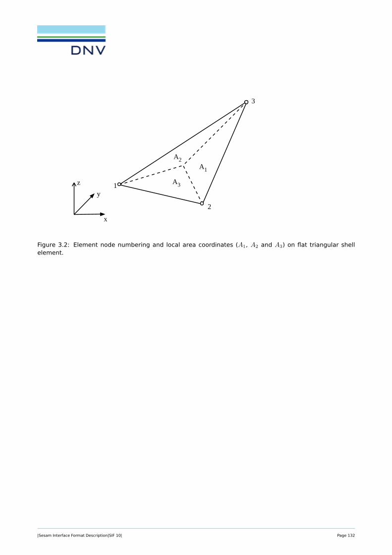
INPUT INTERFACE FILE SESAMPage Date Program Version5-44 01-NOV-1996 6
ELTYP=25: Flat Triangular Thin Shell (FTRS), /2/ FTRS(25)
• 3 nodes• 3 x 5 degrees of freedom• linear element sides• isotropic or anisotropic material data• deformations considered:
bending, shear and translational strain• constant element thickness• element loads:
- initial strain (temperature loads)- surface forces- line loads- line moment load- gravitational load- general inertia load
Figure 5-23 Element node numbering and local area coordinates (A1, A2 and A3) on flat triangularshell element.
x
1
2
3
y
z
A2A1
A3
Figure 3.2: Element node numbering and local area coordinates (A1, A2 and A3) on flat triangular shellelement.
|Sesam Interface Format Description|SIF 10| Page 132
Data types used for this element:
Data type Mandatory Note
GELMNT1 yes
GELREF1 yes
GNODE yes
GCOORD yes
GELTH yes
MISOSEL yes MISOSEL or MORSMEL is mandatory.
MORSMEL yes
MTRMEL Sometimes referred to from MORSMEL.
BEUSLO
BELLO2
BEISTE
BGRAV
BNACCLO
The following restrictions apply to the data types:
GELREF1 - INTNO and ISPONO are not read because number of integration and stress points are con-stant in the program and can not be set by user.
- GEONO / OPT should be set>0 because no thickness variation is allowed for this elementtype.
BELLO2 - The SIDE definition is not used.
BEUSLO - This element type is only able to calculate surface loads which are acting perpendicular tothe element surface. For LOTYP=2 (loads given in component form), the in-plane compo-nents are ignored by the program.
When line load (BELLO2) is specified for one of the element sides, then the relation between local nodenumbers and loaded line will be:
• LINE = 1 – means line load betweeen node 2 and node 3
• LINE = 2 – means line load betweeen node 1 and node 3
• LINE = 3 – means line load betweeen node 1 and node 2
|Sesam Interface Format Description|SIF 10| Page 133

INPUT INTERFACE FILE SESAMPage Date Program Version5-46 01-NOV-1996 6
The following restrictions are put on the data types:
GELREF INTNO and ISPONO are not read because number of integration and stress points are con-stant in the program and cannot be set by user.GEONO / OPT should be set>0 because no thickness variation is allowed for this elementtype.
BEUSLO This element type is only able to calculate surface loads which are acting perpendicular to theelement surface. Hence LOTYP=1 (normal pressure) should be used. If LOTYP=2 (loadsgiven in component form) are specified, the in-plane components are ignored by the program.Surface loads are always referred to the middle plane of these elements, i.e. SIDE=2 (neednot be specified).
Figure 5-24 Constant line load in element plane and linear variation of component normal to the plane
FTRS(25)
x
1
2
3
y
z
Figure 3.3: Constant line load in the element plane and linear variation of component normal to the plane.
Back to Section 3 ELEMENT TYPES
|Sesam Interface Format Description|SIF 10| Page 134

3.46 FQAS: Flat Quadrilateral Thin Shell – Drilling degree of freedom
Element Type 60, see reference [7] for the plate bending formulaton (FQUS), and reference [2] for themembrane formulation.
• 4 nodes
• 4 × 6 = 24 degrees of freedom
• linear element sides
• isotropic or anisotropic material data
• deformations considered:
– bending,
– shear, and
– translational strain
• constant element thickness
• element loads:
– initial strain (temperature load)
– surface forces
– line loads
– line moment load
– gravitational load
– general inertia load
SESAM INPUT INTERFACE FILEProgram Version Date Page6 01-NOV-1996 5-41
ELTYP=24: Flat Quadrilateral Thin Shell (FQUS), /2/ FQUS(24)
• 4 nodes• 4 x 5 degrees of freedom• linear element sides• isotropic or anisotropic material data• deformations considered:
bending, shear and translational strain• constant element thickness• element loads:
- initial strain (temperature loads)- surface forces- line loads- line moment load- gravitational load- general inertia loade
Figure 5-21 Element node numbering on flat quadrilateral shell element.
x
1
4
2
3
y
z
Figure 3.4: Element node numbering on flat quadrilateral shell element.
|Sesam Interface Format Description|SIF 10| Page 135

|Sesam Interface Format Description|SIF 10| Page 136

Data types used for this element:
Data type Mandatory Note
GELMNT1 yes
GELREF1 yes
GNODE yes
GCOORD yes
GELTH yes
MISOSEL yes MISOSEL or MORSMEL is mandatory.
MORSMEL yes
MTRMEL Sometimes referred to from MORSMEL.
BEUSLO
BELLO2
BEISTE
BGRAV
BNACCLO
The following restrictions apply to the data types:
GELREF1 - INTNO and ISPONO are not read because number of integration and stress points are con-stant in the program and can not be set by user.
- No thickness variation is allowed for this element. If thickness variation is specified by theGEONO / OPT option, the finite element program executing this element must use a meanthickness calculated from the nodal thicknesses.
BELLO2 - The SIDE definition is not used.
BEUSLO - This element type is only able to calculate surface loads which are acting perpendicular tothe element surface. For LOTYP=2 (loads given in component form), the in-plane compo-nents are ignored by the program.
When line load (BELLO2) is specified for one of the element sides, then the relation between local nodenumbers and loaded line will be:
• LINE = 1 – means line load betweeen node 1 and node 2
• LINE = 2 – means line load betweeen node 2 and node 3
• LINE = 3 – means line load betweeen node 3 and node 4
• LINE = 4 – means line load betweeen node 4 and node 1
|Sesam Interface Format Description|SIF 10| Page 137

SESAM INPUT INTERFACE FILEProgram Version Date Page6 01-NOV-1996 5-43
The following restrictions are put on the data types:
GELREF - INTNO and ISPONO are not read because number of integration and stress points areconstant in the program and can not be set by user.- No thickness variation is allowed for this element. If thickness variation is specifed bythe GEONO / OPT option, the finite element program executing this element must use amean thickness calculated from the nodal thicknesses.
BEUSLO This element type is only able to calculate surface loads which are acting perpendicular to theelement surface. Hence LOTYP=1 (normal pressure) should be used. If LOTYP=2 (loadsgiven in component form) are specified, the in-plane components are ignored by the program.Surface loads are always referred to the middle plane of these elements, i.e. SIDE=2 (neadnot be specified).
Figure 5-22 Linear variation of line load component normal to the element plane and in the plane.
FQUS(24)
x
1
4
2
3
y
z
Figure 3.5: Linear variation of line load component normal to the element plane and in the element plane.
Back to Section 3 ELEMENT TYPES
|Sesam Interface Format Description|SIF 10| Page 138

3.47 HCQS: Heterosis Curved Quadrilateral Shell
Element Type 61
SESAM INPUT INTERFACE FILEProgram Version Date Page6 01-NOV-1996 5-117
ELTYP=61: Heterosis Curved Quadrilateral HCQS(61)Shell (HCQS),
• 9 nodes• 9 x 6 degrees of freedom• curved element shape• isotropic or anisotropic material data• deformations considered:
bending, shear and translational strain• parabolically varying element thickness• element loads:
- initial strain- surface forces- line loads- gravitational load- general inertia load
Figure 5-60 Element node numbering. Global Cartesian and local normalized coordinate system.
When line load is specified, the relation between local node numbers and loaded line will go:
ξη
ζ
2
3
4
5
6
7
8
1
η= 1
x
ξ= 1
ξ= − 1
ζ= 1
ζ= − 1
η= − 1
y
z
ξη
ζ
9
|Sesam Interface Format Description|SIF 10| Page 139

INPUT INTERFACE FILE SESAMPage Date Program Version5-118 01-NOV-1996 6
LINE=1 means line load along the line defined by the nodes 3, 4 and 5LINE=2 means line load along the line defined by the nodes 2, 9 and 6LINE=3 means line load along the line defined by the nodes 1, 8 and 7LINE=4 means line load along the line defined by the nodes 7, 6 and 5LINE=5 means line load along the line defined by the nodes 8, 9 and 4LINE=6 means line load along the line defined by the nodes 1, 2 and 3
The orientation of the local nodal coordinate system is related to the nodenumbering sequence (see Figure 5-60). The positive ζ-direction, normal to the element middlesurface, is chosen according to the normal conventionof the right hand rule, i.e. the positive ζ-direction is found when the node numbers are followed in ascendingorder, counterclockwise.
The SIDE definition on the BEUSLO records is as follows:
SIDE=1 means that load is given on the element surface where ζ= -1,SIDE=2 that ζ= 0 is loaded, andSIDE=3 that ζ= 1 is loaded.
Data types for this element:
GELMNT1 *GNODE *GCOORD *GELREF1 *GELINTGELTH *GELSTRPMISOSEL * orMISOPL * orMORSSEL *MTRSELBEUSLOBELLO2BEISTEBGRAVBNACCLO
*) Mandatory
HCQS(61)
|Sesam Interface Format Description|SIF 10| Page 140

SESAM INPUT INTERFACE FILEProgram Version Date Page6 01-NOV-1996 5-119
The following restrictions are put on the data types.
BELLO2 The SIDE-definition is not used.
HCQS(61)
Back to Section 3 ELEMENT TYPES
|Sesam Interface Format Description|SIF 10| Page 141

3.48 THTS: Flat 3-noded Thick Triangular Shell
Figure 3.6: Element node numbering, and geometric and kinematic data for the 3-node, linear, triangularelement, THTS.
3.48.1 Element Type 63
Reference [4].
• 3 nodes
• 3 × 5 (6) = 15 (18) degrees of freedom
• linear element sides
• isotropic or anisotropic material data
• deformations considered:
– strain due to bending – linear through the thickness of the element
– transverse shear strain due to bending – constant through the thickness of the element
– in-plane strain due to membrane action – constant through the thickness of the element
• linear element thickness
• element loads:
– initial strain (temperature load)
|Sesam Interface Format Description|SIF 10| Page 142

– surface forces
– line loads
– line moment load
– gravitational load
– general inertia load
3.48.2 Data types used
Data type Mandatory Note
GELMNT1 yes
GELREF1 yes
GNODE yes
GCOORD yes
GELTH yes
MISOSEL yes MISOSEL
MORSSEL yes or MORSSEL is mandatory.
MTRSEL Sometimes referred to from MORSSEL.
BEUSLO
BELLO2
BEISTE
BGRAV
BNACCLO
3.48.3 Restrictions
The following interpretations and restrictions apply to the data types:
GELREF1- INTNO and ISPONO are not yet read and thus the number of integration and stress pointsare constant in the program.
- The element can model linear variation of the thickness. At present the element input datahandles one thickness. I.e. the current implementation has constant thickness.
BELLO2 - The SIDE definition is not used.
BEUSLO- Loads are computed as if they act in the middle-plane (for local z = 0) of the element.
When line load (BELLO2) is specified for one of the element sides, then the relation between local nodenumbers and loaded line will be:
• LINE = 1 – means line load betweeen node 2 and node 3
• LINE = 2 – means line load betweeen node 1 and node 3
|Sesam Interface Format Description|SIF 10| Page 143
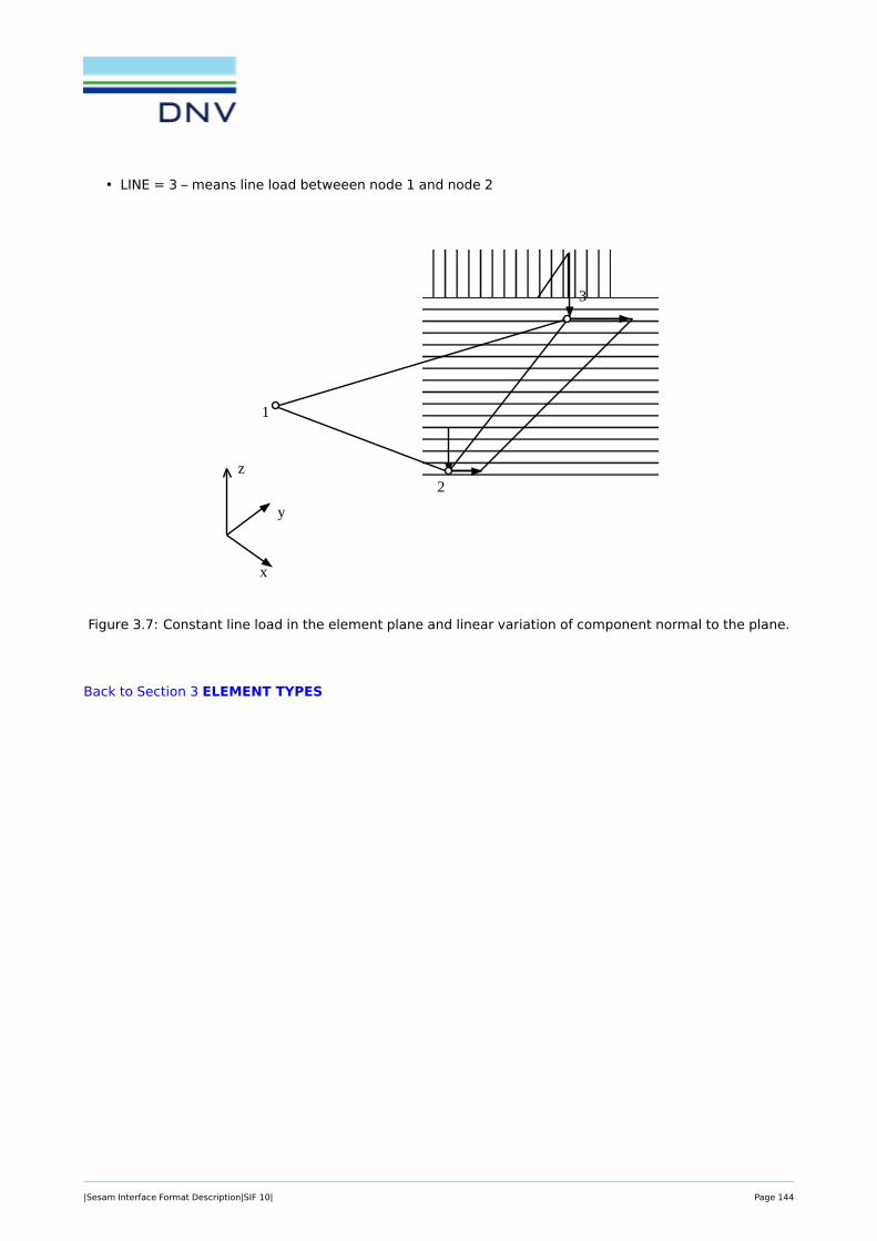
• LINE = 3 – means line load betweeen node 1 and node 2
INPUT INTERFACE FILE SESAMPage Date Program Version5-46 01-NOV-1996 6
The following restrictions are put on the data types:
GELREF INTNO and ISPONO are not read because number of integration and stress points are con-stant in the program and cannot be set by user.GEONO / OPT should be set>0 because no thickness variation is allowed for this elementtype.
BEUSLO This element type is only able to calculate surface loads which are acting perpendicular to theelement surface. Hence LOTYP=1 (normal pressure) should be used. If LOTYP=2 (loadsgiven in component form) are specified, the in-plane components are ignored by the program.Surface loads are always referred to the middle plane of these elements, i.e. SIDE=2 (neednot be specified).
Figure 5-24 Constant line load in element plane and linear variation of component normal to the plane
FTRS(25)
x
1
2
3
y
z
Figure 3.7: Constant line load in the element plane and linear variation of component normal to the plane.
Back to Section 3 ELEMENT TYPES
|Sesam Interface Format Description|SIF 10| Page 144
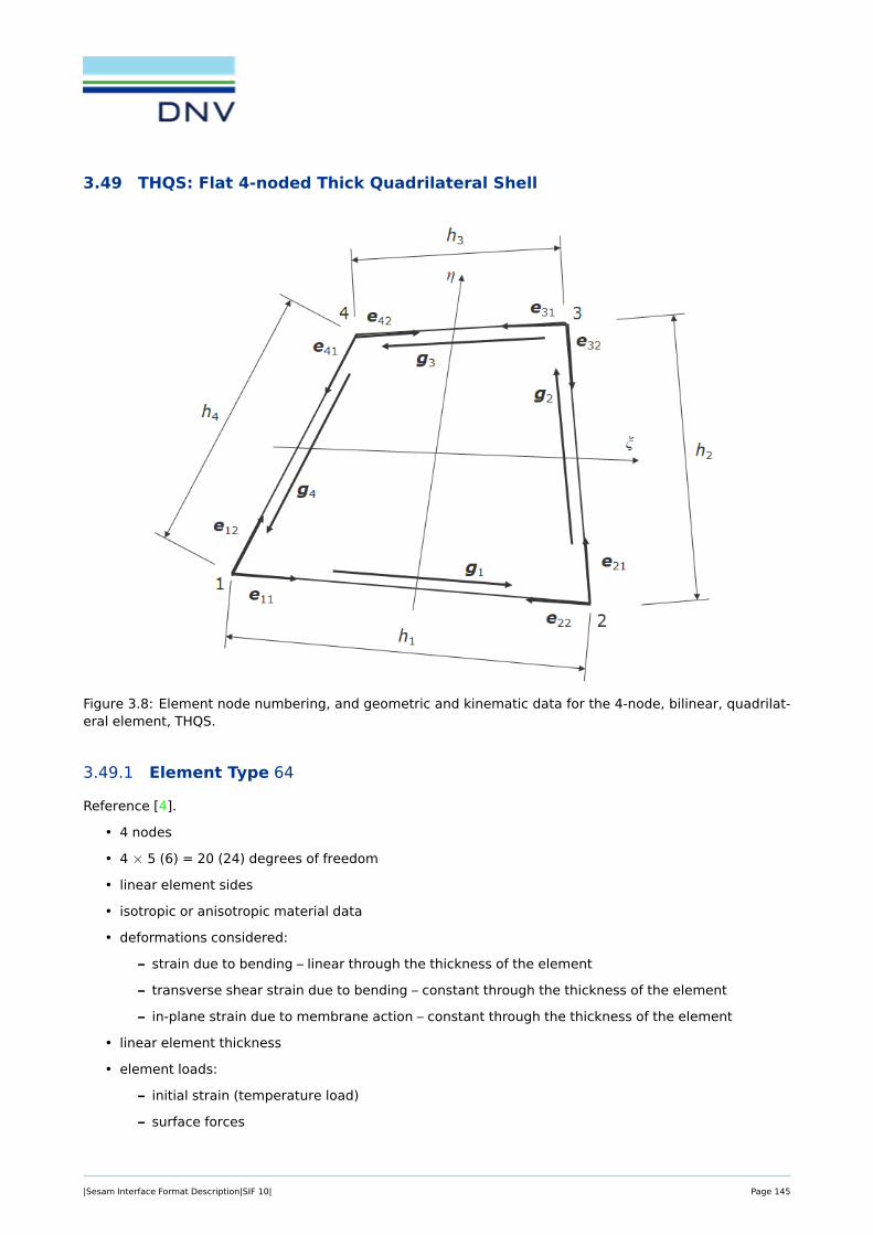
3.49 THQS: Flat 4-noded Thick Quadrilateral Shell
Figure 3.8: Element node numbering, and geometric and kinematic data for the 4-node, bilinear, quadrilat-eral element, THQS.
3.49.1 Element Type 64
Reference [4].
• 4 nodes
• 4 × 5 (6) = 20 (24) degrees of freedom
• linear element sides
• isotropic or anisotropic material data
• deformations considered:
– strain due to bending – linear through the thickness of the element
– transverse shear strain due to bending – constant through the thickness of the element
– in-plane strain due to membrane action – constant through the thickness of the element
• linear element thickness
• element loads:
– initial strain (temperature load)
– surface forces
|Sesam Interface Format Description|SIF 10| Page 145

– line loads
– line moment load
– gravitational load
– general inertia load
3.49.2 Data types used
Data type Mandatory Note
GELMNT1 yes
GELREF1 yes
GNODE yes
GCOORD yes
GELTH yes
MISOSEL yes MISOSEL
MORSSEL yes or MORSSEL is mandatory.
MTRSEL Sometimes referred to from MORSSEL.
BEUSLO
BELLO2
BEISTE
BGRAV
BNACCLO
3.49.3 Restrictions
The following interpretations and restrictions apply to the data types:
GELREF1- INTNO and ISPONO are not yet read and thus the number of integration and stress pointsare constant in the program.
- The element can model linear variation of the thickness. At present the element input datahandles one thickness. I.e. the current implementation has constant thickness.
BELLO2 - The SIDE definition is not used.
BEUSLO- Loads are computed as if they act in the middle-plane (for local z = 0) of the element.
When line load (BELLO2) is specified for one of the element sides, then the relation between local nodenumbers and loaded line will be:
• LINE = 1 – means line load betweeen node 1 and node 2
• LINE = 2 – means line load betweeen node 2 and node 3
• LINE = 3 – means line load betweeen node 3 and node 4
|Sesam Interface Format Description|SIF 10| Page 146

• LINE = 4 – means line load betweeen node 4 and node 1
SESAM INPUT INTERFACE FILEProgram Version Date Page6 01-NOV-1996 5-43
The following restrictions are put on the data types:
GELREF - INTNO and ISPONO are not read because number of integration and stress points areconstant in the program and can not be set by user.- No thickness variation is allowed for this element. If thickness variation is specifed bythe GEONO / OPT option, the finite element program executing this element must use amean thickness calculated from the nodal thicknesses.
BEUSLO This element type is only able to calculate surface loads which are acting perpendicular to theelement surface. Hence LOTYP=1 (normal pressure) should be used. If LOTYP=2 (loadsgiven in component form) are specified, the in-plane components are ignored by the program.Surface loads are always referred to the middle plane of these elements, i.e. SIDE=2 (neadnot be specified).
Figure 5-22 Linear variation of line load component normal to the element plane and in the plane.
FQUS(24)
x
1
4
2
3
y
z
Figure 3.9: Linear variation of line load component normal to the element plane and in the element plane.
Back to Section 3 ELEMENT TYPES
|Sesam Interface Format Description|SIF 10| Page 147

3.50 MATR: General Matrix Element
Element Type 70
INPUT INTERFACE FILE SESAMPage Date Program Version5-120 01-NOV-1996 6
ELTYP=70: General Matrix Element (MATR) MATR(70)
This element is a way of transferring stiffness / damping / mass matrices and / or load / displacement / velocity/ acceleration vectors between different models or analysis programs.
• variable number of nodes - maximum 999 nodes• possible with different number of degrees of freedom in each node• real or complex matrices and vectors• possible with e.g. frequency dependent matrices• stiffness matrix• damping matrix• mass matrix• nodal load vectors• no element loads• nodal displ. / velocity / acceleration vectors
Figure 5-61 Example of 4 noded stiffness and load matrix / vector, with 6, 6, 3 and 6 degrees offreedom in the nodes respectively and 2 loadcases.
K44
K33
K22
K11
K23 K24
K34 R3
K12 K13 K14 R1
R2
R4
NDOF:
6NDOF: 6 3 6 1LLC:
6
6
3
6
R3
R1
R2
R4
2
|Sesam Interface Format Description|SIF 10| Page 148

SESAM INPUT INTERFACE FILEProgram Version Date Page6 01-NOV-1996 5-121
Data types for this element:
Figure 5-62 Normal data reference for a matrix element with 4 nodes and 2 loadcases. The element ishaving stiffness, mass, damping, load and resulting displacement matrices / vectors. At
least some of the vectors / matrices are also frequency dependent.
AMATRIX 1 AMDSTIFF 2
AMDDAMP 2 AMDMASS 2
AMDLOAD 2 AMDDISP 3
AMDFREQ AMDVELO 3
AMDACCL 3 GCOORD 1
GELMNT1 1 GELMNT2GELREF1 1 GNODE 1
MATR(70)
AMDSTIFF
GELMNT1
AMDSTIFF
AMDSTIFF
AMDSTIFF
GNODEGCOORD
AMDMASS AMDDAMP AMDLOAD
AMDSTIFF
AMDSTIFF
AMDSTIFF
AMDSTIFF
AMDSTIFF
AMDSTIFF
AMDMASS
AMDMASS
AMDMASS
AMDMASS
AMDMASS
AMDMASS
AMDMASS
AMDMASS
AMDMASS
AMDDAMP
AMDDAMP
AMDDAMP
AMDDAMP
AMDDAMP
AMDDAMP
AMDDAMP
AMDDAMP
AMDDAMP
AMDLOAD
AMDLOAD
AMDLOAD
AMDLOAD
AMDLOAD
AMDLOAD
AMDLOAD
GCOORD
GCOORD
GCOORD
GNODE
GNODE
GNODE
AMATRIX
AMDDISP
AMDDISP
AMDDISP
AMDDISP
AMDDISP
AMDDISP
AMDDISP
AMDDISP
GELREF1
AMDFREQ
1 Mandatory2 At least one of these records must be present.3 Nodal results may alternatively be defined through records described in ’SIF, Results Interf. File, File Descr.’.
See also figure 5-63.
|Sesam Interface Format Description|SIF 10| Page 149

INPUT INTERFACE FILE SESAMPage Date Program Version5-122 01-NOV-1996 6
Below is a figure showing the datatypes for nodal displacement, velocity or acceleration results associated witha matrix element, when using the records described in the ’SIF, Results Interf. File, File Descr.’ In the examplethe results are displacements.
Figure 5-63 Normal data reference for results defined on records described in the ’SIF, Results Interf.File, File Descr.’ for a matrix element with 4 nodes and 2 loadcases.
AMATRIX 1 RDRESREF 1
GCOORD 1 RVNODACC2
GNODE 1 RVNODDIS 2
RDNODRES 1 RVNODVEL2
MATR(70)
RVNODDIS
RVNODDIS
RVNODDIS
RVNODDIS
GCOORD
RVNODDIS
RVNODDIS
RVNODDIS
RVNODDIS
GCOORD
GCOORD
GCOORD
AMATRIX
RDRESREF
RDRESREF
LLC
LLC
Local LoadCase number
RDNODRES
GNODE
GNODE
GNODE
GNODE
1 Mandatory.2 At least one of these records must be present.
|Sesam Interface Format Description|SIF 10| Page 150

Back to Section 3 ELEMENT TYPES
|Sesam Interface Format Description|SIF 10| Page 151

3.51 GHEX: General Hexahedron
Element Type 100, . . . , 163
SESAM INPUT INTERFACE FILEProgram Version Date Page6 01-NOV-1996 5-123
ELTYP=100,...163: General Hexahedron (GHEX), /2/ GHEX
• 21 to 27 nodes• (21 to 27) x 3 degrees of freedom• curved element sides• isotropic or anisotropic material data• deformations considered: translational strain• element loads:
- initial strain (temperature load)- surface forces- line loads- gravitational load- general inertia load
Figure 5-64 General hexahedron with local nodenumbering and corresponding surface numbering
The element may be without some of the nodes. Which nodes are not present is reflected in the element num-ber:100 The basic element with node 1 to 20 and node 27 present. 101 Nodes 1 to 20, node 21 and node 27 are present.102 Nodes 1 to 20, node 22 and node 27 are present.103 Nodes 1 to 20, node 21, node 22 and node 27 are present.ETC.
z
x
y
4
3
1 2
6
5
7
8
23
4
56
12
910
11
19
20
1415
16
1718
1
13 local node no. 11
surface no. 6
24
2321
22
25
26
27
|Sesam Interface Format Description|SIF 10| Page 152

INPUT INTERFACE FILE SESAMPage Date Program Version5-124 01-NOV-1996 6
If node 21 is present, 1 is added to the basic element type number.If node 22 is present, 2 is added to the basic element type number.If node 23 is present, 4 is added to the basic element type number.If node 24 is present, 8 is added to the basic element type number.If node 25 is present, 16 is added to the basic element type number.If node 26 is present, 32 is added to the basic element type number.If more than one of these nodes are present, the sum of the additions above is added.
element type number Node position contains node number
Node positions: 21 22 23 24 25 26 27100 - - - - - - 21101 21 - - - - - 22102 21 - - - - 22103 21 22 - - - - 23104 - - 21 - - - 22105 21 - 22 - - - 23106 - 21 22 - - - 23107 21 22 23 - - - 24108 - - - 21 - - 22109 21 - - 22 - - 23110 - 21 - 22 - - 23111 21 22 - 23 - - 24112 - - 21 22 - - 23113 21 - 22 23 - - 24114 - 21 22 23 - - 24115 21 22 23 24 - - 25116 - - - - 21 - 22117 21 - - - 22 - 23118 - 21 - - 22 - 23119 21 22 - - 23 - 24120 - - 21 - 22 - 23121 21 - 22 - 23 - 24122 - 21 22 - 23 - 24123 21 22 23 - 24 - 25124 - - - 21 22 - 23125 21 - - 22 23 - 24126 - 21 - 22 23 - 24127 21 22 - 23 24 - 25128 - - 21 22 23 - 24129 21 - 22 23 24 - 25130 - 21 22 23 24 - 25131 21 22 23 24 25 - 26132 - - - - - 21 22133 21 - - - - 22 23134 - 21 - - - 22 23
GHEX
|Sesam Interface Format Description|SIF 10| Page 153

SESAM INPUT INTERFACE FILEProgram Version Date Page6 01-NOV-1996 5-125
135 21 22 - - - 23 24136 - - 21 - - 22 23137 21 - 22 - - 23 24138 - 21 22 - - 23 24139 21 22 23 - - 24 25140 - - - 21 - 22 23141 21 - - 22 - 23 24142 - 21 - 22 - 23 24143 21 22 - 23 - 24 25144 - - 21 22 - 23 24145 21 - 22 23 - 24 25146 - 21 22 23 - 24 25147 21 22 23 24 - 25 26148 - - - - 21 22 23149 21 - - - 22 23 24150 - 21 - - 22 23 24151 21 22 - - 23 24 25152 - - 21 - 22 23 24153 21 - 22 - 23 24 25154 - 21 22 - 23 24 25155 21 22 23 - 24 25 26156 - - - 21 22 23 24157 21 - - 22 23 24 25158 - 21 - 22 23 24 25159 21 22 - 23 24 25 26160 - - 21 22 23 24 25161 21 - 22 23 24 25 26162 - 21 22 23 24 25 26163 21 22 23 24 25 26 27
GHEX
|Sesam Interface Format Description|SIF 10| Page 154

INPUT INTERFACE FILE SESAMPage Date Program Version5-126 01-NOV-1996 6
Figure 5-65 Typical general hexahedron
When surface loads are specified for the element side, the surface numbers shown are used for identification ofthe side in question. The node numbers 21 to 27 signifies the node position number. The actual node numberwithin the actual element is 20 + number of nodes up to node position which are present in the actual element.Which node number shall actually be used in the tables below may be determined by the table of nodes in nodeposition above. If the node position in question is empty the number of nodes on the line or side is one less, andcompacted when the line is missing one node.
The local node numbering for each side is defined as follows:
Node number
1 2 3 4 5 6 7 8 (9)Side no.
1 7 8 1 9 13 20 19 12 (21)2 5 11 17 16 15 10 3 4 (22)3 1 2 3 10 15 14 13 9 (23)4 7 12 19 18 17 11 5 6 (24)5 7 6 5 4 3 2 1 8 (25)6 19 20 13 14 15 16 17 18 (26)
GHEX
z
x
y 1
23
4
5
6
15
10
11
16
12
7
20
13
914
8
19
1817
ξ=-1
η=-1
ξ
ηζ
ξ=+1
η=+1
21
22
24
23
27
26
25
|Sesam Interface Format Description|SIF 10| Page 155

SESAM INPUT INTERFACE FILEProgram Version Date Page6 01-NOV-1996 5-127
When line load is specified, the relation between the local node numbers and the loaded line will be as follows:
Node number1 2 3
Line no.1 1 2 32 3 4 53 5 6 74 7 8 15 1 9 136 3 10 157 5 11 178 7 12 199 13 14 15
10 15 16 1711 17 18 1912 19 20 1313 8 (25) 414 6 (25) 215 9 (23) 1016 2 (23) 1417 10 (22) 1118 4 (22) 1619 11 (24) 1220 6 (24) 1821 12 (21) 922 8 (21) 2023 20 (26) 1624 14 (26) 18
GHEX
|Sesam Interface Format Description|SIF 10| Page 156

INPUT INTERFACE FILE SESAMPage Date Program Version5-128 01-NOV-1996 6
Data types used for this element:
GELMNT1 *GNODE *GCOORD *GELREF1 *GELSTRPMISOSEL * orMISOPL * orMORSSOL *MTRSOLBEUSLOBELLO2BEISTEBGRAVBNACCLO
*) Mandatory
The following restrictions are put on the data types
BELLO2 The SIDE definition is not used. The load components are given nodewise in globalcoordinates.
BEUSLO Only one side identification can be given in SIDE.
GHEX
Back to Section 3 ELEMENT TYPES
|Sesam Interface Format Description|SIF 10| Page 157

4 STRUCTURAL CONCEPTS AND CONCEPT ATTRIBUTES
4.1 The structure concept model
Figure 4.1: The structure concept model
The structure concept may represent concepts on any level (assemblies or basic parts).
The function of a concept is determined by its type and role.
The structure concepts can contain other structure concepts (part concepts).
The structure concept can refer joint concepts.
The structure concept has a Finite Element representation given on lowest concept level.
The structure concept has properties available via a property list and property selectors.
The structure properties are recursively inherited from parent concepts if not specified on current level.
There is only one property list to each concept.
Each property selector may be referred to from several property lists (i.e. concepts may share propertyselectors).
Each property value may be referred to from several property selectors (i.e. property selectors mayshare property values).
|Sesam Interface Format Description|SIF 10| Page 158

4.2 Structure concept descriptions
SCONCEPT Structure concept definition see Section 4.2.1
SCONMESH Structure concept finite element representation see Section 4.2.2
SCONPLIS Structure concept property list see Section 4.2.3
SPROCODE Structure concept code checking attributes see Section 4.2.4
SPROECCE Structure concept eccentricity attributes see Section 4.2.5
SPROHYDR Structure concept hydrodynamic attributes see Section 4.2.6
SPROMATR Structure concept material attributes see Section 4.2.7
SPROORIE Structure concept orientation attributes see Section 4.2.8
SPROPILE Structure concept pile attributes see Section 4.2.9
SPROSECT Structure concept cross section attributes see Section 4.2.10
SPROSEGM Structure concept segment attributes see Section 4.2.11
SPROSELE Structure concept property selectors see Section 4.2.12
SPROSOIL Structure concept soil data see Section 4.2.13
TDSCONC Structure concept referable text see Section 4.2.14
The structure concept data types are described on the following pages.
|Sesam Interface Format Description|SIF 10| Page 159

4.2.1 SCONCEPT: Structure concept definition
This data type defines a structural concept, with definition of the function of the concept, and reference toits parent, parts and joints concepts.
Data type definition:
SCONCEPT Data type reference.
NFIELD Number of data fields on this data type (including this field).
→ IRCON Concept reference number (unique).
SCONTYPE Structure concept type number (see Table 4.1).
SCONROLE Structure concept role number (see Table 4.2).
IRPARENT Parent concept reference number ( or 0.0 if no parent).
NPART Number of part concepts.
NJOINT Number of joint (connection) concepts.
Repeat for NPART
IRPART Part concept reference numbers.
Next PART
Repeat for NJOINT
IRJOINT Joint concept reference numbers.
Next JOINT
Note:
• Typically, a member will refer to n number of part concepts (segments), and two joint concepts.
Table 4.1: Structure concept type definitions
SCONTYPE Data type Comment
0 Undefined
1 Joint Is a connection between Members.
2 Segment Is a part of a Member with uniform or tapered cross section.
3 Member Runs between two Joints.
4 Pile joint Is a start or end node for a Pile.
5 Pile segment Is a part of a Pile with uniform cross section.
6 Pile Runs between two Pile joints.
7 Segmented beam One or more segments, where internal segments may be cansand cones. Stubs may only be at beam end segments. Mayinclude no reference to joints.
|Sesam Interface Format Description|SIF 10| Page 160

Table 4.2: Structure concept role definitions
SCONROLE Data type Comment
0 Undefined
1 Stub Is a Segment role.
2 Can Is a Segment role.
3 Cone Is a Segment role.
4 MidSection Is a Segment role.
5 Chord Is a Member role.
6 Brace Is a Member role.
7 MainPile Is a Pile role.
8 InnerPile Is a Pile role.
9 ConductorPile Is a Pile role.
10 PileGroup Is a Pile role.
Back to Section 4.2 Structure concept descriptions
|Sesam Interface Format Description|SIF 10| Page 161

4.2.2 SCONMESH: Structure concept finite element representation
This data type defines the finite element representation of the lowest level structural concepts, i.e. theconnection to internal element or node identities.
Data type definition:
SCONMESH Data type reference.
NFIELD Number of data fields on this data type (including this field).
→ IRCON Concept reference number (unique).
NUMREP Number of finite element representation types.
Repeat for NUMREP
TYPREP finite element representation type (see Table 4.3).
NFEREP Number of finite element representations.
Repeat for NFEREP
IRFEREP finite element representation reference numbers (internal id).
Next FEREP
Next REP
Note:
• SCONMESH to be given on lowest concept level, i.e. for segments and joints.
Table 4.3: Definition of finite element representation types
TYPREP Data type Comment
1 Node Refers internal node number (GNODE).
2 Element Refers internal element number (GELMNT1).
3 Set Refers internal set number (GSETMEMB) (not to be imple-mented).
Back to Section 4.2 Structure concept descriptions
|Sesam Interface Format Description|SIF 10| Page 162

4.2.3 SCONPLIS: Structure concept property list
This data type defines the property list. Through the list the concept indirectly refers to actual properties.The property items do not contain the properties themselves, but refer to them through property selectors.
There is only one property list to each concept.
Data type definition:
SCONPLIS Data type reference.
NFIELD Number of data fields on this data type (including this field).
→ IRCON Concept reference number (unique).
NUMPSEL Number of property selectors.
Repeat for NUMPSEL
TYPEPROP Property attribute type number (must be a SPROSELE in first im-plementation) (see Table 4.4).
IRPSELE Property selector reference numbers (internal id).
Next PSEL
Table 4.4: Definition of property attribute types
TYPEPROP Data type Type of property Comment
1 SPROSELE Structure concept property selectors
2 SPROSECT Structure concept cross section attributes
3 SPROMATR Structure concept material attributes
4 SPROSEGM Structure concept segment attributes E.g. cone data.
5 SPROHYDR Structure concept hydrodynamic attributes
6 SPROCODE Structure concept code checking attributes
7 SPROORIE Structure concept orientation attributes
8 SPROECCE Structure concept eccentricity attributes
9 SPROPILE Structure concept pile attributes
Back to Section 4.2 Structure concept descriptions
|Sesam Interface Format Description|SIF 10| Page 163
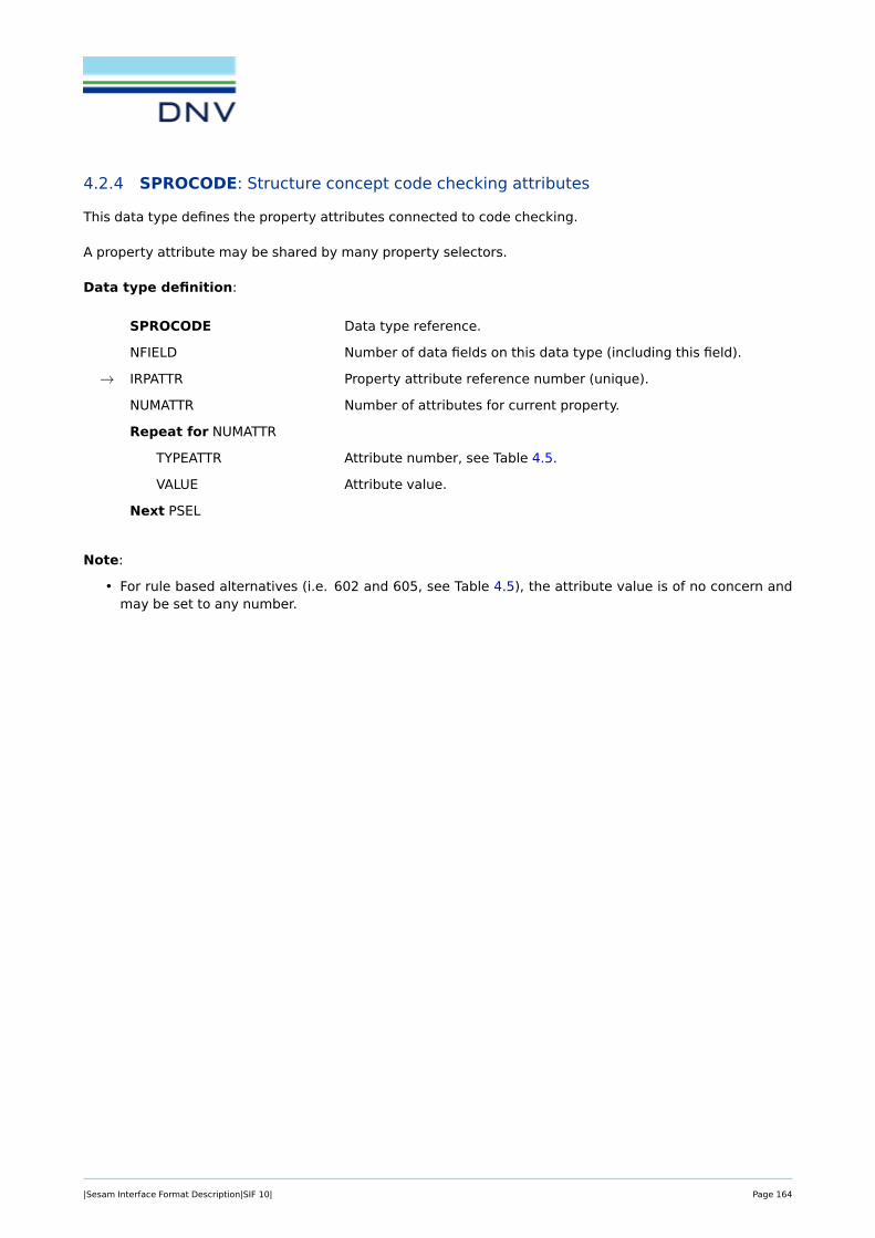
4.2.4 SPROCODE: Structure concept code checking attributes
This data type defines the property attributes connected to code checking.
A property attribute may be shared by many property selectors.
Data type definition:
SPROCODE Data type reference.
NFIELD Number of data fields on this data type (including this field).
→ IRPATTR Property attribute reference number (unique).
NUMATTR Number of attributes for current property.
Repeat for NUMATTR
TYPEATTR Attribute number, see Table 4.5.
VALUE Attribute value.
Next PSEL
Note:
• For rule based alternatives (i.e. 602 and 605, see Table 4.5), the attribute value is of no concern andmay be set to any number.
|Sesam Interface Format Description|SIF 10| Page 164

Table 4.5: Definition of property values
TYPEATTR Attribute value Comment
600 Buckling length Y Concept local axis.
601 Buckling length Z Concept local axis.
602 Buckling length joint-to-joint
603 Effective length factor Y Concept local axis.
604 Effective length factor Z Concept local axis.
605 Calculated acc. to NPD-NS3472
606 Moment amplification factor Y-direction Concept local axis.
607 Moment amplification factor Z-direction Concept local axis.
608 Moment amplification method Y-direction Concept local axis.
609 Moment amplification method Z-direction Concept local axis.
610 Unbraced length upper flange
611 Unbraced length lower flange
612 Stiffener spacing member
613 Stiffener spacing cone
614 Bending coefficient
615 Bending coefficient rulebased
Back to Section 4.2 Structure concept descriptions
|Sesam Interface Format Description|SIF 10| Page 165

4.2.5 SPROECCE: Structure concept eccentricity attributes
This data type defines the property attributes connected to eccentricity / gap of concepts.
A property attribute may be shared by many property selectors.
Data type definition:
SPROECCE Data type reference.
NFIELD Number of data fields on this data type (including this field).
→ IRPATTR Property attribute reference number (unique).
NUMATTR Number of attributes for current property.
Repeat for NUMATTR
TYPEATTR Attribute number, see Table 4.6.
VALUE Attribute value.
Next PSEL
Table 4.6: Definition of property values
TYPEATTR Attribute value Comment
Back to Section 4.2 Structure concept descriptions
|Sesam Interface Format Description|SIF 10| Page 166

4.2.6 SPROHYDR: Structure concept hydrodynamic attributes
This data type defines the hydrodynamic property attributes. A property attributes may be shared by manyproperty selectors.
Data type definition:
SPROHYDR Data type reference.
NFIELD Number of data fields on this data type (including this field).
→ IRPATTR Property attribute reference number (unique).
NATTR Number of attributes for current property.
Repeat for NATTR
TYPEATTR Attribute number, see Table 4.7.
VALUE Attribute value.
Next ATTR
Note:
• Even if SPROHYDR is revised to include the additional hydrodynamic attributes as shown in the tableabove, there will still be a need to document actual values used in Wajac, as Wajac input may overridethe information stored on SPROHYDR. For documenting Wajac values used, we have WHYCOEL andWHYPREL.
Table 4.7: Definition of property values
TYPEATTR Attribute value Comment
500 Flooding coefficient 1.0 = completely flooded (open).
0.0 = not flooded (sealed).
501 Drag coefficient X (CDx) Concept local co-ordinate system.
502 Drag coefficient Y (CDy)
503 Drag coefficient Z (CDz)
504 Inertia coefficient X (CMx) Concept local co-ordinate system.
505 Inertia coefficient Y (CMy)
506 Inertia coefficient Z (CMz)
507 Hydrodynamic diameter
508 Buoyancy nonflooded area
509 Buoyancy flooded area
510 Marine growth
|Sesam Interface Format Description|SIF 10| Page 167

Back to Section 4.2 Structure concept descriptions
|Sesam Interface Format Description|SIF 10| Page 168

4.2.7 SPROMATR: Structure concept material attributes
This data type defines the material property attributes. The property value contains the actual values for aparticular material definition.
A property attribute may be shared by many property selectors.
Data type definition:
SPROMATR Data type reference.
NFIELD Number of data fields on this data type (including this field).
→ IRPATTR Property attribute reference number (unique).
NUMATTR Number of attributes for current property.
Repeat for NUMATTR
TYPEATTR Attribute number, see Table 4.8.
VALUE Attribute value.
Next PSEL
Table 4.8: Definition of property values
TYPEATTR Attribute value Comment
300 Yield strength Currently in use by pile only.
301 Tensile strength Currently not in use.
Back to Section 4.2 Structure concept descriptions
|Sesam Interface Format Description|SIF 10| Page 169

4.2.8 SPROORIE: Structure concept orientation attributes
This data type defines the property attributes connected to orientation of concepts.
A property attribute may be shared by many property selectors.
Data type definition:
SPROORIE Data type reference.
NFIELD Number of data fields on this data type (including this field).
→ IRPATTR Property attribute reference number (unique).
NUMATTR Number of attributes for current property.
Repeat for NUMATTR
TYPEATTR Attribute number, see Table 4.9.
VALUE Attribute value.
Next PSEL
Table 4.9: Definition of property values
TYPEATTR Attribute value Comment
Back to Section 4.2 Structure concept descriptions
|Sesam Interface Format Description|SIF 10| Page 170

4.2.9 SPROPILE: Structure concept pile attributes
This data type defines the specific property attributes connected to pile concepts.
A property attribute may be shared by many property selectors.
Data type definition:
SPROPILE Data type reference.
NFIELD Number of data fields on this data type (including this field).
→ IRPATTR Property attribute reference number (unique).
NUMATTR Number of attributes for current property.
Repeat for NUMATTR
TYPEATTR Attribute number, see Table 4.10.
VALUE Attribute value.
Next PSEL
Table 4.10: Definition of property values
TYPEATTR Attribute value Comment
900 Pile tip boundary condition "Tip code".
901 Pile head fixed to dummy pile, i.e.rigidely connected to
Refers to internal node number in the struc-ture (dummy pile not modelled).
Back to Section 4.2 Structure concept descriptions
|Sesam Interface Format Description|SIF 10| Page 171
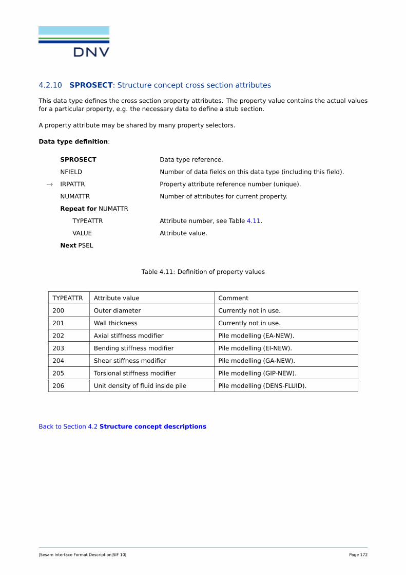
4.2.10 SPROSECT: Structure concept cross section attributes
This data type defines the cross section property attributes. The property value contains the actual valuesfor a particular property, e.g. the necessary data to define a stub section.
A property attribute may be shared by many property selectors.
Data type definition:
SPROSECT Data type reference.
NFIELD Number of data fields on this data type (including this field).
→ IRPATTR Property attribute reference number (unique).
NUMATTR Number of attributes for current property.
Repeat for NUMATTR
TYPEATTR Attribute number, see Table 4.11.
VALUE Attribute value.
Next PSEL
Table 4.11: Definition of property values
TYPEATTR Attribute value Comment
200 Outer diameter Currently not in use.
201 Wall thickness Currently not in use.
202 Axial stiffness modifier Pile modelling (EA-NEW).
203 Bending stiffness modifier Pile modelling (EI-NEW).
204 Shear stiffness modifier Pile modelling (GA-NEW).
205 Torsional stiffness modifier Pile modelling (GIP-NEW).
206 Unit density of fluid inside pile Pile modelling (DENS-FLUID).
Back to Section 4.2 Structure concept descriptions
|Sesam Interface Format Description|SIF 10| Page 172

4.2.11 SPROSEGM: Structure concept segment attributes
This data type defines the property attributes connected to specific segment information.
A property attribute may be shared by many property selectors.
Data type definition:
SPROSEGM Data type reference.
NFIELD Number of data fields on this data type (including this field).
→ IRPATTR Property attribute reference number (unique).
NUMATTR Number of attributes for current property.
Repeat for NUMATTR
TYPEATTR Attribute number, see Table 4.12.
VALUE Attribute value.
Next PSEL
Table 4.12: Definition of property values
TYPEATTR Attribute value Comment
400 Cone diameter at start Currently not in use.
401 Cone diameter at end Currently not in use.
402 Cone wall thickness Currently not in use.
403 Cone inclination Currently not in use.
404 Segment length Currently not in use.
Back to Section 4.2 Structure concept descriptions
|Sesam Interface Format Description|SIF 10| Page 173

4.2.12 SPROSELE: Structure concept property selectors
This data type defines the property selector. The property selector represents the sharing of property valuesbetween different concepts.
A property selector selects one or more property attribute types. It may be referenced by many concepts.Changing the content of a property selector will change the connected properties of all the concepts thatreferences it.
Data type definition:
SPROSELE Data type reference.
NFIELD Number of data fields on this data type (including this field).
→ IRPSELE Property selector reference number (unique).
NUMTYPE Number of property attribute types.
Repeat for NUMTYPE
TYPEPROP Property attribute type number (ref. Table 4.1).
IRPATTR Property attribute reference numbers (internal id).
Next TYPE
Note:
• A property selector may only refer to one property attribute of each type, e.g. only one SPROSECTmay be referred from each SPROSELE.
Back to Section 4.2 Structure concept descriptions
|Sesam Interface Format Description|SIF 10| Page 174
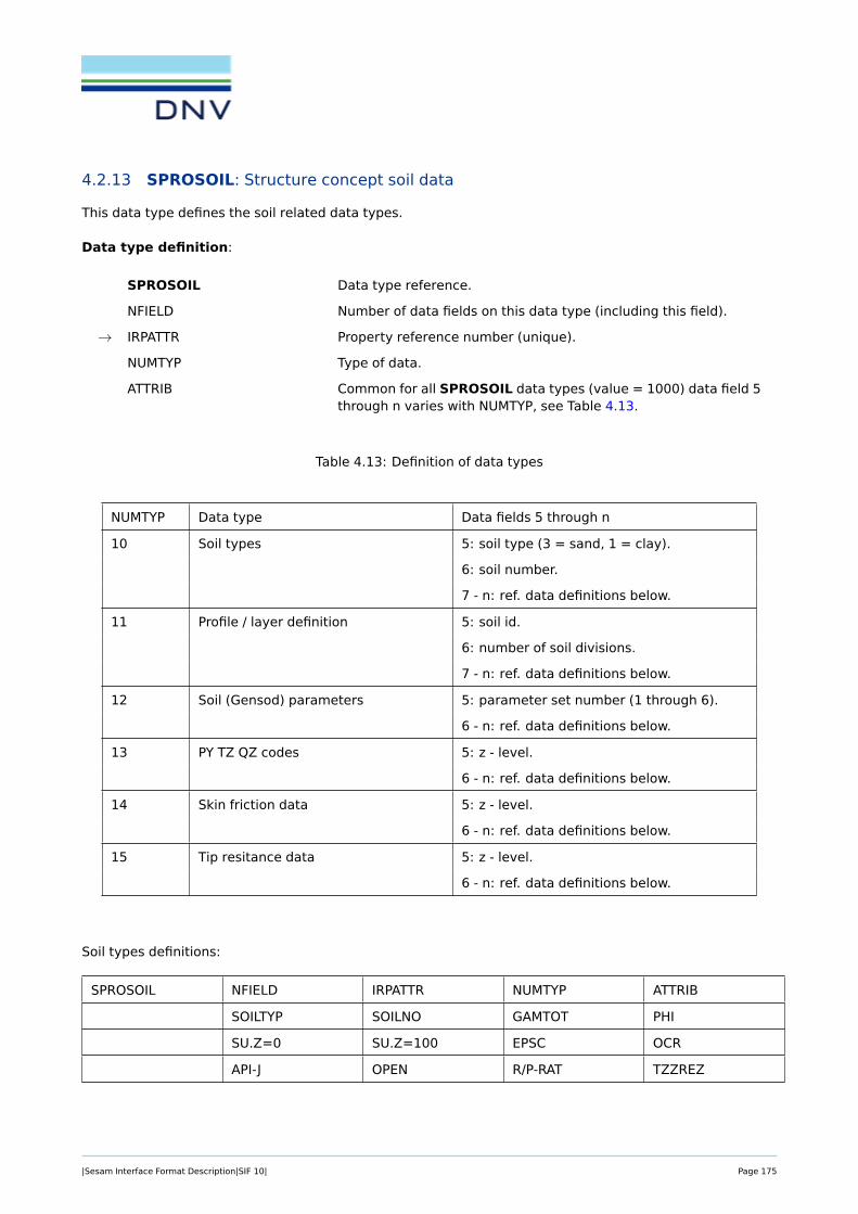
4.2.13 SPROSOIL: Structure concept soil data
This data type defines the soil related data types.
Data type definition:
SPROSOIL Data type reference.
NFIELD Number of data fields on this data type (including this field).
→ IRPATTR Property reference number (unique).
NUMTYP Type of data.
ATTRIB Common for all SPROSOIL data types (value = 1000) data field 5through n varies with NUMTYP, see Table 4.13.
Table 4.13: Definition of data types
NUMTYP Data type Data fields 5 through n
10 Soil types 5: soil type (3 = sand, 1 = clay).
6: soil number.
7 - n: ref. data definitions below.
11 Profile / layer definition 5: soil id.
6: number of soil divisions.
7 - n: ref. data definitions below.
12 Soil (Gensod) parameters 5: parameter set number (1 through 6).
6 - n: ref. data definitions below.
13 PY TZ QZ codes 5: z - level.
6 - n: ref. data definitions below.
14 Skin friction data 5: z - level.
6 - n: ref. data definitions below.
15 Tip resitance data 5: z - level.
6 - n: ref. data definitions below.
Soil types definitions:
SPROSOIL NFIELD IRPATTR NUMTYP ATTRIB
SOILTYP SOILNO GAMTOT PHI
SU.Z=0 SU.Z=100 EPSC OCR
API-J OPEN R/P-RAT TZZREZ
|Sesam Interface Format Description|SIF 10| Page 175

SOILTYP Soil type (1 = clay, 3 = sand (2 not in use)).
SOILNO Soil id (number).
GAMTOT Total unit weigth.
PHI Angle of internal friction (degrees).
SU.Z=0 Undrained shear strength at z=0.
SU.Z=100 Undrained shear strength at z=100.
EPSC Strain at half of max stress.
OCR Over-consolidation ratio.
API-J J factor for API code.
OPEN Code for open gap (0 or 1).
R/P-RAT Residual / peak skin friction ratio.
TZZES T-Z curve z displacement from peak to residual skin friction.
Soil profile / layer definitions:
SPROSOIL NFIELD IRPATTR NUMTYP ATTRIB
SOILID NDIV Z-BOTM(1) NOFLAY(1)
SOILNO(1) . . . . . . . . .
Z-BOTM(NDIV) NOFLAY(NDIV) SOILNO(NDIV)
SOILID Soil profile id (number). Currently only id 1 allowed.
NDIV Number of soil divisions (types) in profile.
Z-BOTM Z level (global co-ordinates) at bottom of division (type) n.
NOFLAY Number of layers within the soil division (type).
SOILNO Soil type to be used in soil division.
Gensod control data definitions, (SETNUM = 1):
SPROSOIL NFIELD IRPATTR NUMTYP ATTRIB
SETNUM MUDLINE ZONINF RFTZ
MUDLINE The Z level defining mudline.
ZONINF The value to be used for zone of influence.
RFTZ The value to be used for curve fitting.
Gensod control data definitions, CONTROL SECTION (SETNUM = 2):
|Sesam Interface Format Description|SIF 10| Page 176

SPROSOIL NFIELD IRPATTR NUMTYP ATTRIB
SETNUM CONFRC CONLTH GAMMAW
ATMPRS ZCYCL SUSTIF
CONFRC Old-force-unit = confrc * new-force-unit 1mn = 1000*1kn.
CONLTH Old-length-unit = conlth * new-length-unit 1m = 3.28*1ft.
GAMMAW Unit weight of water.
ATMPRS Atmospheric pressure.
ZCYCL Z-level down to which cyclic p-y data shall be generated.
SUSTIF Use stiff clay p-y procedures if su.gt.sustf (api only).
Gensod control data definitions, MATERIAL COEFFICIENT SECTION (SETNUM = 3):
SPROSOIL NFIELD IRPATTR NUMTYP ATTRIB
SETNUM SFTPHI SFSU SFSKF
SFSIGT
SFTPHI Material coefficient on tan(phi).
SFSU Material coefficient on undrained shear strength.
SFSKF Material coefficient on pile skin friction.
SFSIGT Material coefficient on pile tip resistance.
Gensod control data definitions, PILE DIAM. AND GROUP EFFECT SECTION (SETNUM = 4):
SPROSOIL NFIELD IRPATTR NUMTYP ATTRIB
SETNUM ESOL0 ESOL1 POSAVR
ESOL0 E-soil for group effect calculation:
ESOL1 ESOIL(Z) = ESOL0 + ESOL1*Z
POSAVR Soil average poisson ratio for group effects.
Gensod control data definitions, SOIL SURFACE & GROUND WATER SECTION (SETNUM = 5):
SPROSOIL NFIELD IRPATTR NUMTYP ATTRIB
SETNUM ZSURF SCRGEN SCRLOC
continued . . .
|Sesam Interface Format Description|SIF 10| Page 177

SLOPE ZGRWT GAMPWP
ZSURF Z-level of non-scoured soil surface.
SCRGEN Depth of general scour below zsurf.
SCRLOC Depth of local scour below zsurf.
SLOPE Side slope (degrees) of local scour holes.
ZGRWT Z-level of ground water table.
GAMPWP Unit weight of ground water (used to find pore water pressure).
Gensod control data definitions, LOADS AT SOIL SURFACE SECTION (SETNUM = 6):
SPROSOIL NFIELD IRPATTR NUMTYP ATTRIB
SETNUM SIGSRF DPEMB AEMB
BEMB DPCIRC RADIUS
SIGSRF Vertical stress at surface.
DPEMB Vertical stress under embankment loading.
AEMB Width a of embankment sloping part.
BEMB Pile position with respect to embankment toe (positive outside).
DPCIRC Vertical stress under circular loaded area.
RADIUS Radius of circular loaded area (pile is in center).
PY - TZ - QZ code definitions:
SPROSOIL NFIELD IRPATTR NUMTYP ATTRIB
Z-LEVEL PY-CODE TZ-CODE QZ-CODE
Z-LEVEL Z-level where values are given.
PY-CODE PY code to be used.
TZ-CODE TZ code to be used.
QZ-CODE QZ code to be used.
Skin friction & tip resistance data definitions:
SPROSOIL NFIELD IRPATTR NUMTYP ATTRIB
continued . . .
|Sesam Interface Format Description|SIF 10| Page 178

Z-LEVEL SKIN-CMP SKIN-TNS G0-SOIL
DS/DIA-RAT SIG-TIP POIS DT/DIA-RAT
Z-LEVEL Z-level where values are given.
SKIN-CMP Peak skin friction in compression.
SKIN-TNS Peak skin friction in tension.
G0-SOIL Initial value of soil shear modulus.
DS/DIA-RAT Ratio between dipl. to reach peak skin friction and pile diameter.
SIG-TIP Peak tip stress acting at pile tip.
POIS Soil Poisson ration.
DT/DIA-RAT Ratio between dipl. to reach peak tip stress and pile diameter.
Back to Section 4.2 Structure concept descriptions
|Sesam Interface Format Description|SIF 10| Page 179

4.2.14 TDSCONC: Structure concept referable text
TDSCONC NFIELD → IRCON CODNAM CODTXT
Name
Comment line
. . .
Comment line
This data type will associate a name to a structure concept.
NFIELD Number of numeric data fields at this data type before text data (MAX =1024).
IRCON Concept reference number (unique).
CODNAM Coded dimension of the Name:CODNAM = NLNAM*100 + NCNAM. The inverse relation will then be:NLNAM = integer part of (CODNAM/100)NCNAM = remaindering of (CODNAM/100)NLNAM number lines used to store the name. Legal range = [0,1]
= 0, no name defined= 1, name is defined
NCNAM - number of characters in the name. Legal range = [0,64]
CODTXT Coded dimension of the Comment:CODTXT = NLTXT*100 + NCTXT. The inverse relation will then be:NLTXT = integer part of (CODTXT/100)NCTXT = remaindering of (CODTXT/100)NLTXT - number of lines used to store the comment. Legal range = [0,5]
= 0, no comments defined≥ 1, number of physical records with comments
NCTXT - number of characters in the comment – each comment line mustbe of the same length. Legal range = [0,64]
Name A user set name.
Comment line User set comment lines.
Note:
• TDSCONC is currently in use only for SCONCEPT of type Member and Pile.
Back to Section 4.2 Structure concept descriptions
|Sesam Interface Format Description|SIF 10| Page 180

4.2.15 Example
Figure 4.2: The structure concept example model
The simple model has a member with a conical transition and stub at one end, see Figure 4.2 above.
The following example SIF file shows:
• Concepts with types and roles, and the part and joint relations.
• Specification of material yield strength.
• References to FE representation with three beam elements.
• Specification of joint coordinates. (Defined via reference to internal node number.)
The instansiated object model is as follows:
|Sesam Interface Format Description|SIF 10| Page 181

The material attributes are assigned to the Brace101:
SESAM Interface Input file (T1.FEM) representing "Brace 101":
IDENT 1.00000000E+00 1.00000000E+00 3.00000000E+00 0.00000000E+00
DATE 1.00000000E+00 0.00000000E+00 4.00000000E+00 7.20000000E+01
DATE: 10-Sep-2016 TIME: 14:05:46
PROGRAM: SESAM GeniE VERSION: V7.3-15 07-Mar-2016
COMPUTER: X86 Windows INSTALLATION:
USER: lzhan ACCOUNT:
GNODE 1.00000000E+00 1.00000000E+00 6.00000000E+00 1.23456000E+05
GNODE 3.00000000E+00 2.00000000E+00 6.00000000E+00 1.23456000E+05
GNODE 4.00000000E+00 3.00000000E+00 6.00000000E+00 1.23456000E+05
GNODE 2.00000000E+00 4.00000000E+00 6.00000000E+00 1.23456000E+05
GCOORD 1.00000000E+00 0.00000000E+00 0.00000000E+00 0.00000000E+00
GCOORD 2.00000000E+00 2.78543019E+00 0.00000000E+00 1.11417210E+00
GCOORD 3.00000000E+00 4.64238358E+00 0.00000000E+00 1.85695338E+00
GCOORD 4.00000000E+00 1.00000000E+01 0.00000000E+00 4.00000000E+00
GELMNT1 1.00000000E+00 1.00000000E+00 1.50000000E+01 0.00000000E+00
1.00000000E+00 2.00000000E+00 0.00000000E+00 0.00000000E+00
GELMNT1 2.00000000E+00 2.00000000E+00 1.50000000E+01 0.00000000E+00
2.00000000E+00 3.00000000E+00 0.00000000E+00 0.00000000E+00
GELMNT1 3.00000000E+00 3.00000000E+00 1.50000000E+01 0.00000000E+00
3.00000000E+00 4.00000000E+00 0.00000000E+00 0.00000000E+00
GPIPE 1.00000000E+00 7.40000010E-01 8.00000012E-01 2.99999993E-02
1.00000000E+00 1.00000000E+00 0.00000000E+00 0.00000000E+00
GBEAMG 1.00000000E+00 0.00000000E+00 7.25707933E-02 1.07731372E-02
5.38656861E-03 5.38656861E-03 0.00000000E+00 2.69328430E-02
1.34664215E-02 1.34664215E-02 3.63221057E-02 3.63221057E-02
0.00000000E+00 0.00000000E+00 8.89800023E-03 8.89800023E-03
GPIPE 2.00000000E+00 5.50000012E-01 6.00000024E-01 2.50000004E-02
1.00000000E+00 1.00000000E+00 0.00000000E+00 0.00000000E+00
GBEAMG 2.00000000E+00 0.00000000E+00 4.51603979E-02 3.73984477E-03
1.86992239E-03 1.86992239E-03 0.00000000E+00 1.24661485E-02
6.23307424E-03 6.23307424E-03 2.26086304E-02 2.26086304E-02
0.00000000E+00 0.00000000E+00 4.13541729E-03 4.13541729E-03
GPIPE 3.00000000E+00 6.39999986E-01 6.99999988E-01 2.99999993E-02
1.00000000E+00 1.00000000E+00 0.00000000E+00 0.00000000E+00
GBEAMG 3.00000000E+00 0.00000000E+00 6.31460175E-02 7.10076885E-03
3.55038443E-03 3.55038443E-03 0.00000000E+00 2.02879105E-02
1.01439552E-02 1.01439552E-02 3.16151790E-02 3.16151790E-02
|Sesam Interface Format Description|SIF 10| Page 182

0.00000000E+00 0.00000000E+00 6.73799962E-03 6.73799962E-03
MISOSEL 1.00000000E+00 2.10000003E+11 3.00000012E-01 7.85000000E+03
0.00000000E+00 1.20000004E-05 0.00000000E+00 0.00000000E+00
GUNIVEC 1.00000000E+00 -3.71390700E-01 0.00000000E+00 9.28476691E-01
GUNIVEC 2.00000000E+00 -3.71390671E-01 0.00000000E+00 9.28476751E-01
GUNIVEC 3.00000000E+00 -3.71390671E-01 0.00000000E+00 9.28476691E-01
GELREF1 1.00000000E+00 1.00000000E+00 0.00000000E+00 0.00000000E+00
0.00000000E+00 0.00000000E+00 0.00000000E+00 0.00000000E+00
1.00000000E+00 0.00000000E+00 0.00000000E+00 1.00000000E+00
GELREF1 2.00000000E+00 1.00000000E+00 0.00000000E+00 0.00000000E+00
0.00000000E+00 0.00000000E+00 0.00000000E+00 0.00000000E+00
3.00000000E+00 0.00000000E+00 0.00000000E+00 2.00000000E+00
GELREF1 3.00000000E+00 1.00000000E+00 0.00000000E+00 0.00000000E+00
0.00000000E+00 0.00000000E+00 0.00000000E+00 0.00000000E+00
2.00000000E+00 0.00000000E+00 0.00000000E+00 3.00000000E+00
IEND 0.00 0.00 0.00 0.00
Example of the new data types:
TDSCONC and SCONCEPT for Brace 101:
TDSCONC 4.00000000E+00 1.01000000E+02 1.08000000E+02 0.00000000E+00
BRACE101
SCONCEPT 1.20000000E+01 1.01000000E+02 3.00000000E+00 6.00000000E+00
0.00000000E+00 3.00000000E+00 2.00000000E+00 1.04000000E+02
1.05000000E+02 1.06000000E+02 1.02000000E+02 1.03000000E+02
SCONCEPT and SCONMESH for Joint 2:
SCONCEPT 3.00000000E+00 1.03000000E+02 1.00000000E+00
SCONMESH 6.00000000E+00 1.03000000E+02 1.00000000E+00 1.00000000E+00
1.00000000E+00 4.00000000E+00
SCONCEPT and SCONMESH for Stub 1:
SCONCEPT 5.00000000E+00 1.04000000E+02 2.00000000E+00 1.00000000E+00
1.01000000E+02
SCONMESH 6.00000000E+00 1.04000000E+02 1.00000000E+00 2.00000000E+00
1.00000000E+00 1.00000000E+00
SCONCEPT and SCONMESH for Cone 1:
SCONCEPT 5.00000000E+00 1.05000000E+02 2.00000000E+00 3.00000000E+00
1.01000000E+02
SCONMESH 6.00000000E+00 1.05000000E+02 1.00000000E+00 2.00000000E+00
1.00000000E+00 2.00000000E+00
SCONPLIS, SPROSELE and SPROMATR supporting concept 101 (referes to one property value; Yieldstrength with value = 3.45e+8, given in SPROMATR no. 28, via SPROSELE no. 10):
SCONPLIS 5.00000000E+00 1.01000000E+02 1.00000000E+00 1.00000000E+00
1.00000000E+01
SPROSELE 5.00000000E+00 1.00000000E+01 1.00000000E+00 3.00000000E+00
2.80000000E+01
SPROMATR 5.00000000E+00 2.80000000E+01 1.00000000E+00 3.00000000E+02
3.45000000E+08
Back to Section 4.2 Structure concept descriptions
|Sesam Interface Format Description|SIF 10| Page 183

5 FIRST LEVEL DATA
5.1 Additional Element Data
First level data
ACFD General Crack Data see Section 5.1.1
ADDATA Additional User defined Basic Element Data see Section 5.1.2
|Sesam Interface Format Description|SIF 10| Page 184

5.1.1 ACFD: General Crack Data
ACFD → IGLB → ILOK NEP IMOD
MKP DX DY DZ
I(1) I(2) . . . I(NEP)
NSIF ISIF(1) ISIF(2) . . .
ISIF(NSIF)
A crack is defined by a set of ACFD data types on the Interface file. There is one ACFD-data type foreach crack front node.
IGLB Sequence numbering of crack front nodes.
ILOK External node number of the crack front node.
NEP Perturbation option for nodes to be perturbed.
< 0 Nodes not supplied; use all side nodes closest to the crack tip andnodes coinciding with ILOK.
= 0 Crack tip node only is perturbed.
> 0 Number of nodes supplied. The nodes are perturbed in additionto the crack tip node.
IMOD Conversion option.
Governs the conversion from crack driving force to stress intensity factoraccording to:
= 1 K =√E/(1− ν2)
√G
= 2 K =√EG
= 3 K =√E/(1 + ν2)
√G
where K is stress intensity factor, G is crack driving force, E is YoungâAZsmodulus and ν is PoissonâAZs ratio.
MKP Perturbation direction option:
= 0 Perturbation direction given in (DX,DY,DZ)
> 0 MKP=external node number of node which defines direction to-gether with ILOK
= -1 Automatic computation by analysis program (only relevant fordouble crack surface).
= -2 Point (DX,DY,DZ) in crack surface is given.
The perturbation direction must be normal to the crack front and tangentialto the crack surface.
DY, DY, DZ Coordinates (in super element global co-ordinate system) as MKP specifies.
I(1)
I(2) If NEP > 0: External node numbers of nodes to be perturbed together withcrack front node ILOK. Nodes with the same position as ILOK may be leftout of specification.
...
|Sesam Interface Format Description|SIF 10| Page 185

I(NEP)
NSIF Number of associated nodes used in calculation of Stress Intensity Factors(SIF) in node ILOK.
= 2 Node ILOK is a mid-side node.
= 4 Node ILOK is a corner node.
= 0 Node ILOK is a corner node and the last node along crack front.NSIF = 0 is treated as NSIF = 4 (four associated nodes).
Note that two crack fronts may be present in a super element. Separationbetween the two crack fronts is identified with NSIF = 0. IGLB goes from 1to the total number of crack front nodes along the two crack fronts.
ISIF(1)
ISIF(2) External node numbers for nodes in crack surface....
ISIF(NSIF)
|Sesam Interface Format Description|SIF 10| Page 186

Figure 5.1: Definition of local axis system
Back to Section 5.1 Additional Element Data
|Sesam Interface Format Description|SIF 10| Page 187
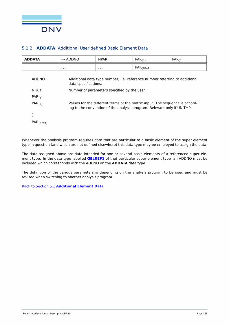
5.1.2 ADDATA: Additional User defined Basic Element Data
ADDATA → ADDNO NPAR PAR(1) PAR(2)
. . . . . . PAR(NPAR)
ADDNO Additional data type number, i.e. reference number referring to additionaldata specifications.
NPAR Number of parameters specified by the user.
PAR(1)
PAR(2) Values for the different terms of the matrix input. The sequence is accord-ing to the convention of the analysis program. Relevant only if UNIT=0.
...
PAR(NPAR)
Whenever the analysis program requires data that are particular to a basic element of the super elementtype in question (and which are not defined elsewhere) this data type may be employed to assign the data.
The data assigned above are data intended for one or several basic elements of a referenced super ele-ment type. In the data type labelled GELREF1 of that particular super element type an ADDNO must beincluded which corresponds with the ADDNO on the ADDATA data type.
The definition of the various parameters is depending on the analysis program to be used and must berevised when switching to another analysis program.
Back to Section 5.1 Additional Element Data
|Sesam Interface Format Description|SIF 10| Page 188

5.2 Boundary Conditions, Loads and Point Masses
First level data
BAHAMAS Element with Added Mass see Section 5.2.1
BEDRAG1 Hydrodynamic Drag and Damping from Wave LoadProgram
see Section 5.2.2
BEISTE Element with Initial Strain Due to Thermal Expan-sion
see Section 5.2.3
BELFIX Flexible Joint/Hinge see Section 5.2.4
BELLAX Surface Load on Axi-symmetric Solid see Section 5.2.5
BELLO2 Elements with Line Load, Solid, 3D-Shell, 2D-Shell,Membrane and Curved Beam Elements
see Section 5.2.6
BELOAD1 Beam with Line Load see Section 5.2.7
BEMASS1 Hydrodynamic added Mass from Wave Load Pro-gram
see Section 5.2.8
BEUSLO Element with Surface Load see Section 5.2.9
BEUVLO Elements with Volume Force, 3-D Solid, 2-D Shelland Membrane Elements
see Section 5.2.10
BEWAKIN Wave Kinematics see Section 5.2.11
BEWALO1 Element Loads from Wave Load Program see Section 5.2.12
BGRAV Gravitational Load (Constant of Gravity) see Section 5.2.13
BLDEP Node with Linear Dependency see Section 5.2.14
BNACCLO Node with Acceleration Load see Section 5.2.15
BNBCD Node with Boundary Condition see Section 5.2.16
BNDISPL Node with Displacement, Velocity and/or Accelera-tion
see Section 5.2.17
BNDOF Node with Transformation see Section 5.2.18
BNIEQ Nodes with Non-Linear Contact Dependence see Section 5.2.19
BNINCO Node with Initial Condition If Arbitrary Time Depen-dent Loading
see Section 5.2.20
BNLOAD Node with Load see Section 5.2.21
BNLOAX Node with Load (Line Load) for Axi-symmetric Solid(proposal)
see Section 5.2.22
BNMASS Node with Point Mass see Section 5.2.23
BNTEMP Node with Temperature and Derivative for Temper-ature
see Section 5.2.24
BNTRCOS Transformation from Global to Local Co-ordinateSystem, Direction Cosines
see Section 5.2.25
BNWALO Node Load from Wave Load Program see Section 5.2.26
BQDP Node with Simple Quadratic Dependence see Section 5.2.27
|Sesam Interface Format Description|SIF 10| Page 189

BRIGAC Rigid Body Acceleration see Section 5.2.28
BRIGDI Rigid Body Displacement see Section 5.2.29
BRIGVE Rigid Body Velocity see Section 5.2.30
|Sesam Interface Format Description|SIF 10| Page 190

5.2.1 BAHAMAS: Element with Added Mass
BAHAMAS → ELNO NORMAL
ELNO Program defined internal number for the element for which added masscontribution should be computed.
NORMAL Element side normal vector. NORMAL= ±1.0 indicates the direction of thehydrodynamic pressure.
= 1 hydrodynamic pressure direction is out from the element.
= -1 hydrodynamic pressure direction is in to the element.
Back to Section 5.2 Boundary Conditions, Loads and Point Masses
|Sesam Interface Format Description|SIF 10| Page 191
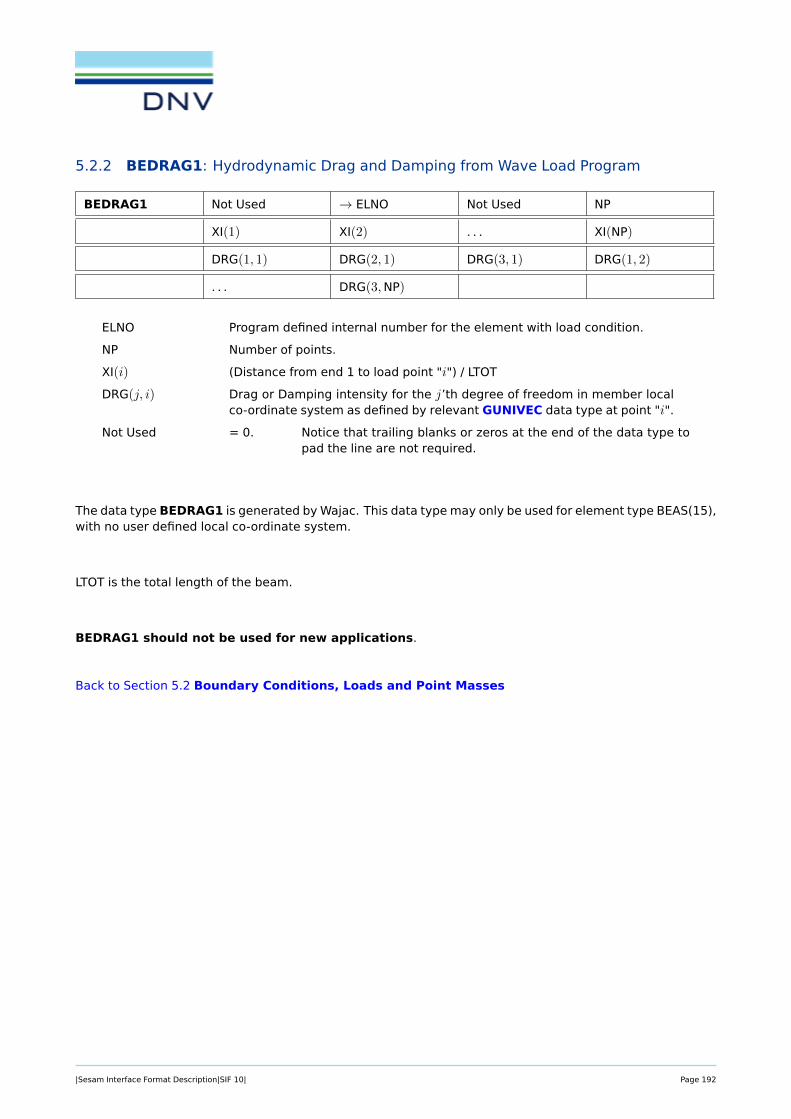
5.2.2 BEDRAG1: Hydrodynamic Drag and Damping from Wave Load Program
BEDRAG1 Not Used → ELNO Not Used NP
XI(1) XI(2) . . . XI(NP)
DRG(1, 1) DRG(2, 1) DRG(3, 1) DRG(1, 2)
. . . DRG(3,NP)
ELNO Program defined internal number for the element with load condition.
NP Number of points.
XI(i) (Distance from end 1 to load point "i") / LTOT
DRG(j, i) Drag or Damping intensity for the j’th degree of freedom in member localco-ordinate system as defined by relevant GUNIVEC data type at point "i".
Not Used = 0. Notice that trailing blanks or zeros at the end of the data type topad the line are not required.
The data type BEDRAG1 is generated by Wajac. This data type may only be used for element type BEAS(15),with no user defined local co-ordinate system.
LTOT is the total length of the beam.
BEDRAG1 should not be used for new applications.
Back to Section 5.2 Boundary Conditions, Loads and Point Masses
|Sesam Interface Format Description|SIF 10| Page 192

5.2.3 BEISTE: Element with Initial Strain Due to Thermal Expansion
BEISTE → LLC LOTYP Not Used TOP
→ ELNO NNOD INTNO T(11)
T(21) . . . T(NNOD1) T(12)
T(22) . . . T(NNOD2)
LLC Local load case number (positive integer number).
LOTYP Load type.
= 1 For all element types including shell elements with constant tem-perature across element thickness.
= 2 For shell elements with temperature difference across elementthickness.
TOP Option to temperature difference specification.
= 1 Only one temperature difference is specified. It will be the samefor all nodes.
= 2 Temperature differences will be specified in all nodes.
ELNO Program defined internal number for the element
NNOD Number of element nodes.
INTNO Integration station reference number to data type GELINT
This reference is usually not used (=0). It means that the program perform-ing the load calculation chooses integration points.
T(11) Temperature difference at node 1, referred to element surface where z=-1.
T(21) Temperature difference at node 2, referred to element surface where z=-1....
T(NNOD1) Temperature difference at node NNOD, referred to element surface wherez=-1.
T(12) Temperature difference at node 1, referred to element surface where z=1.
T(22) Temperature difference at node 2, referred to element surface where z=1....
T(NNOD2) Temperature difference at node NNOD, referred to element surface wherez=1.
Not Used = 0. Notice that trailing blanks or zeros at the end of the data type topad the line are not required.
Reference to element side is used for shell elements with temperature difference across thickness. For allother situations only one temperature difference has to be specified in each node. By "temperature dif-ference at node i" is meant the difference between the present temperature and a reference temperaturewhere no initial strain is acting at the node.
Elements for which BEISTE can be applied:
|Sesam Interface Format Description|SIF 10| Page 193

3.10 BEAS
3.19 FQUS
etc ...
Back to Section 5.2 Boundary Conditions, Loads and Point Masses
|Sesam Interface Format Description|SIF 10| Page 194

5.2.4 BELFIX: Flexible Joint/Hinge
BELFIX → FIXNO OPT TRANO Not Used
A(1) A(2) A(3) A(4)
A(5) A(6)
FIXNO Fixation number to a node.
FIXNO is referenced from the GELREF1 data type.
OPT = 1 A(i) = ai is a value between 0 and 1 that gives the degree offixation (connectivity) to degree of freedom number i in the node.The extreme values of a is described by:
a = 0, fully released
a = 1, fully connected
= 2 A(i) = Ci is the inter element elastic spring stiffness to degree offreedom number i in the node. The degrees of freedom which areneither flexible nor free will be given Ci = −1 (instead of Ci =∞).The relation between Ci and ai is
ai = Ci/(kii + Ci) ≥ 0.0
where kii is the diagonal term of the element stiffness matrix cor-responding to degree of freedom number i of the current node.
= 3 As OPT = 1, where the hinge is located at the end of the beam –and not in the node as for OPT = 1. This option is thus relevantfor eccentric beams.
= 4 As OPT = 2, where the hinge is located at the end of the beam –and not in the node as for OPT = 2. This option is thus relevantfor eccentric beams.
TRANO = -1 The fixation/flexibility (=A(i)) is given in the super element co-ordinate system.
= 0 A(i) is given in the local element co-ordinate system.
> 0 A(i) is given in a local co-ordinate system defined by TRANO,which refers to a transformation matrix given on data type BN-TRCOS. The transformation matrix is defined by transformationfrom global to local system.
A(i) See above (under the explanation of OPT).
Not Used = 0. Notice that trailing blanks or zeros at the end of the data type topad the line are not required.
Back to Section 5.2 Boundary Conditions, Loads and Point Masses
|Sesam Interface Format Description|SIF 10| Page 195

5.2.5 BELLAX: Surface Load on Axi-symmetric Solid
BELLAX → LLC LOTYP COMPLEX Not Used
→ ELNO NDOF INTNO LINE
LD IZERO NFF NFL
NFS NF FC(1,1) FC(1,2)
. . . FC(1,NDOF) FC(2,1) FC(2,2)
. . . FC(2,NDOF) . . . FC(NF,1)
. . . FC(NF,NDOF)
LLC Local load case number (positive integer number).
LOTYP Type of load at the element ELNO.
= 0 not decided whether conservative or non-conservative load.
= 1 conservative load.
= -1 non-conservative load.
COMPLEX Phase shift definition.
= 0 no phase shift.
= 1 phase shift.
Currently not used.
ELNO Program defined internal number for the element with load condition.
NDOF Number of degrees of freedom along the given load line = 3 * the numberof nodes.
INTNO Integration station reference number to data type GELINT
This reference is usually not used (=0). It means that the program perform-ing the load calculation chooses integration points.
Currently not used.
LINE Line specification.
See the element description in section 3.
LD = 1 if loading is symmetric with respect to the q = 0 axis.
= 2 if loading is antisymmetric with respect to the q = 0 axis.
= 3 if loading is not symmetric with respect to the q = 0 axis.
q is the angle co-ordinate of the cylindrical co-ordinate system (r, z, q).
IZERO = 0 if the zero harmonic is NOT included in the Fourier expansion.
= 1 if the zero harmonic is included in the Fourier expansion.
NFF The first non-zero harmonic in the Fourier expansion of the load.
NFL The last non-zero harmonic in the Fourier expansion of the load.
NFS The harmonic increment in the Fourier expansion of the load.
NF The total number of coefficients of the Fourier expansion.
NF = 1 Axi-symmetric load
|Sesam Interface Format Description|SIF 10| Page 196

NF = (NFL NFF)/ NFS + 1 + IZERO for LD = 1, 2 (non axi-symmetricload)
NF = 2 * ((NFL NFF)/ NFS + 1) + IZERO for LD = 3 (non axi-symmetricload)
FC(1,1) The Fourier coefficient for the radial (R) degree of freedom of thefirst node for the first harmonic.
FC(1,2) The Fourier coefficient for the tangential (q) degree of freedom ofthe first node for the first harmonic.
FC(1,3) The Fourier coefficient for the axial (Z) degree of freedom of thefirst node for the first harmonic.
FC(1,4) The Fourier coefficient for the radial (R) degree of freedom of thesecond node for the first harmonic.
...
FC(1,NDOF) The Fourier coefficient for the axial (Z) degree of freedom of thelast node for the first harmonic.
FC(2,1)
FC(2,2)
... The Fourier coefficients for the degrees of freedom of the load linefor the second harmonic.
FC(2,NDOF)
...
...
FC(NF,1)
FC(NF,2)
... The Fourier coefficients for the degrees of freedom of the load linefor the last harmonic.
FC(NF,NDOF)
Not Used = 0. Notice that trailing blanks or zeros at the end of the data type topad the line are not required.
|Sesam Interface Format Description|SIF 10| Page 197

Note:
E.g. SYMMETRIC LOAD
Consider a load line with 3 nodes each with RADIAL (R), TANGENTIAL (q) and AXIAL (Z) degrees offreedom. The loads are described using the zero, first, second and third harmonics.
NDOF = 9
LD = 1
IZERO = 1
NFF = 1
NFL = 3
NFS = 1
NF = 4
FC(1,1) . . . FC(1,9) : Fourier coefficients for the zero harmonic
FC(2,1) . . . FC(2,9) : Fourier coefficients for the first harmonic
FC(3,1) . . . FC(3,9) : Fourier coefficients for the second harmonic
FC(4,1) . . . FC(4,9) : Fourier coefficients for the third harmonic
PRADIAL = FC(1,1) + FC(2,1)cos q + FC(3,1)cos 2q + FC(4,1)cos 3q
PTANGENTIAL = FC(1,2) + FC(2,2)sin q + FC(3,2)sin 2q + FC(4,2)sin 3q
PAXIAL = FC(1,3) + FC(2,3)cos q + FC(3,3)cos 2q + FC(4,3)cos 3q
Similarly the loads for the second and third node on the load line are described using the values 4,5, 6 and 7, 8, 9 respectively for the last index of FC.
SYMMETRIC loads (LD=1) of the RADIAL and AXIAL degrees of freedom are described using coeffi-cients of COSINE, while the TANGENTIAL d.o.f.s are described using coefficients of SINE.
|Sesam Interface Format Description|SIF 10| Page 198

E.g. ANTISYMMETRIC LOAD
Consider a load line with 2 nodes, each with 3 degrees of freedom.
The first node has load in RADIAL(R)and AXIAL(Z)direction. The second node has load in RA-DIAL(R)and TANGENTIAL(q)direction. The loads are described using the second, fifth and eighthharmonics.
NDOF = 6
LD = 2
IZERO = 0
NFF = 2
NFL = 8
NFS = 3
NF = 3
FC(1,1) . . . FC(1,6) : second harmonics
FC(2,1) . . . FC(2,6) : fifth harmonics
FC(3,1) . . . FC(3,6) : eighth harmonics
The loads for the first node on the load line are thus given by:
PRADIAL = FC(1,1) sin 2q + FC(2,1) sin 5q + FC(3,1) sin 8q
PAXIAL = FC(1,3) sin 2q + FC(2,3) sin 5q + FC(3,3) sin 8q
FC(1,2) = FC(2,2) = FC(3,2) = 0.0 (no tangential load)
The loads for the second node on the load line is thus given by:
PRADIAL = FC(1,4) sin 2q + FC(2,4) sin 5q + FC(3,4) sin 8q
PTANGENTIAL = FC(1,5) cos 2q + FC(2,5) cos 5q + FC(3,5) cos 8q
FC(1,6) = FC(2,6) = FC(3,6) = 0.0 (no axial load)
Totally NDOF × NF = 6 × 3 = 18 coefficients will be written.
ANTISYMMETRIC loads of the RADIAL and AXIAL d.o.f.s are described using coefficients of SINE,while the TANGENTIAL degrees of freedom are described using coefficients of COSINE.
|Sesam Interface Format Description|SIF 10| Page 199

E.g. NONSYMMETRIC LOAD
Not implemented in Sestra.
Consider 3 nodes on a load line each with RADIAL(R), AXIAL(Z) and TANGENTIAL(q) degrees offreedom. The loads are described using the zero, first and second harmonics
NDOF = 9
LD = 3
IZERO = 1
NFF = 1
NFL = 2
NFS = 1
NF = 3
FC(1,1) . . . FC(1,9) : Fourier coefficients for the zero harmonic
FC(2,1) . . . FC(2,9) : Fourier coefficients for the first COSINE harmonic
FC(3,1) . . . FC(3,9) : Fourier coefficients for the first SINE harmonic
FC(4,1) . . . FC(4,9) : Fourier coefficients for the second COSINE harmonic
FC(5,1) . . . FC(5,9) : Fourier coefficients for the second SINE harmonic
The loads for the 3 degrees of freedom of the first node on the load line is thus given by.
PRADIAL = FC(1,1) + FC(2,1)cos q + FC(3,1)sin q + FC(4,1)cos 2q + FC(5,1)sin 2q
PTANGENTIAL = FC(1,2) + FC(2,2)cos q + FC(3,2)sin q + FC(4,2)cos 2q + FC(5,2)sin 2q
PAXIAL = FC(1,3) + FC(2,3)cos q + FC(3,3)sin q + FC(4,3)cos 2q + FC(5,3)sin 2q
Similarly the load for the second and third node on the load line is described using the values 4, 5,6 and 7, 8, 9, respectively for the last index of FC.
Back to Section 5.2 Boundary Conditions, Loads and Point Masses
|Sesam Interface Format Description|SIF 10| Page 200

5.2.6 BELLO2: Elements with Line Load, Solid, 3D-Shell, 2D-Shell, Membrane and CurvedBeam Elements
BELLO2 → LLC LOTYP COMPLEX LAYER
→ ELNO NDOF INTNO LINE
SIDE RLOAD(1) RLOAD(2) . . .
. . . . . . RLOAD(NDOF) ILOAD(1)
ILOAD(2) . . . . . . . . .
ILOAD(NDOF)
LLC Local load case number (positive integer number).
LOTYP Type of load at the element ELNO. Decision whether load being force ormoment and if it is conservative or non-conservative. Conservative or non-conservative is usually not of interest to linear programs.
= 0 not decided whether conservative or non-conservative force perlength.
= 1 conservative force per length.
= -1 non-conservative force per length.
= 3 conservative moment per length.
= -3 non-conservative moment per length.
COMPLEX Phase shift definition.
= 0 no phase shift.
= 1 phase shift.
LAYER Layer number for elements with more than one layer.
If LAYER equals 0, the line load will be positioned in the shell layer (in op-position to a stiffener layer).
If more than one shell layer is defined for an element type and LAYER equals0, the programs shall stop and give an error message.
For elements which are treated as one layer in the load calculations (e.g.the sandwich element in Sestra), LAYER does not have any meaning.
ELNO Program defined internal number for the element with load condition.
NDOF Number of translational degrees of freedom along the given load line forline force. For line moment the variable is specifying number of rotationaldegrees of freedom along the given load line.
INTNO Integration station reference number to data type GELINT
This reference is usually not used (=0). It means that the program perform-ing the load calculation chooses integration points.
LINE Line specification.
See the element description in section 3.
SIDE Element side definition.
See the element description in section 3.
|Sesam Interface Format Description|SIF 10| Page 201

RLOAD(1) The real part of the load condition with respect to the first degree of free-dom at current LINE of element ELNO.
RLOAD(2) The real part of the load condition with respect to the second degree offreedom at current LINE of element ELNO.
...
RLOAD(NDOF) The real part of the load condition with respect to the last degree of free-dom at current LINE of element ELNO.
ILOAD(1) The imaginary part of the load condition with respect to the first degree offreedom at current LINE of element ELNO.
ILOAD(2) The imaginary part of the load condition with respect to the second degreeof freedom at current LINE of element ELNO.
...
ILOAD(NDOF) The imaginary part of the load condition with respect to the last degree offreedom at current LINE of element ELNO.
The imaginary numbers follow immediately after the real numbers, i.e. there are no blank fields betweenthe last real number – RLOAD(NDOF) – and the first imaginary number – ILOAD(1). If no phase shift is specified(that is COMPLEX= 0), then the fields or positions ILOAD(1), ILOAD(2), etc. are left out.
For quadrilateral membrane elements line loads can only be specified along element sides.
It will make no sense to specify line moment for membrane and solid type of elements.
Back to Section 5.2 Boundary Conditions, Loads and Point Masses
|Sesam Interface Format Description|SIF 10| Page 202

5.2.7 BELOAD1: Beam with Line Load
BELOAD1 → LLC LOTYP COMPLEX OPT
→ ELNO L1 L2 NDOF
INTNO RLOAD(1) RLOAD(2) . . .
. . . . . . RLOAD(NDOF) ILOAD(1)
ILOAD(2) . . . . . . . . .
ILOAD(NDOF)
LLC Local load case number (positive integer number).
LOTYP Type of load at the element ELNO. Decision whether load being force ormoment and if it is conservative or non-conservative. Conservative or non-conservative is usually not of interest to linear programs.
= 0 not decided whether conservative or non-conservative load.
= 1 True distributed force, conservative load.
= 2 Simulated concentrated force, conservative load.
= 3 True distributed moment, conservative load.
= 4 Simulated concentrated moment, conservative load.
= -1 True distributed force, non-conservative load.
= -2 Simulated concentrated force, non-conservative load.
= -3 True distributed moment, non-conservative load.
= -4 Simulated concentrated moment, non-conservative load.
COMPLEX Phase shift definition.
= 0 no phase shift.
= 1 phase shift.
OPT Option for reference of L1 and L2 (see below).
= 0 L1 and L2 are distances measured from the ends of the flexiblepart of the beam.
= 1 L1 and L2 are distances measured along the beam axis from theprojection of the end nodes on the beam axis.
ELNO Program defined internal number for the element with load condition.
L1 Distance along the beam from end node 1 to the position on the beamwhere the line load starts acting. The distance L1 is in the interval [0,Length–of–the–Beam].
L2 Distance along the beam from end node 2 to the position on the beamwhere the line load ends acting. The distance L2 is in the interval [L1,Length–of–the–Beam].
NDOF Product of last degree of freedom with specified load and the number ofnodes of the beam in question (= 3*NNOD for 3-dimensional beams).
INTNO Integration station reference number to data type GELINT
|Sesam Interface Format Description|SIF 10| Page 203

This reference is usually not used (=0). It means that the program perform-ing the load calculation chooses integration points.
RLOAD(1) The real part of the intensity with respect to the first degree of freedom ofthe first load point.
RLOAD(2) The real part of the global intensity with respect to the second degree offreedom of the first load point.
...
RLOAD(NDOF) The real part of the global intensity with respect to the last degree of free-dom with load of the last load point.
ILOAD(1) The imaginary part of the global intensity with respect to the first degreeof freedom of the first load point.
ILOAD(2) The imaginary part of the global intensity with respect to the second de-gree of freedom of the first load point.
...
ILOAD(NDOF) The imaginary part of the global intensity with respect to the last degreeof freedom with load of the last load point.
The legal degrees of freedom are the translational components, given in the global co-ordinate system.
The imaginary numbers follow immediately after the real numbers, i.e. there are no blank fields betweenthe last real number – RLOAD(NDOF) – and the first imaginary number – ILOAD(1). If no phase shift is specified(that is COMPLEX= 0), then the fields or positions ILOAD(1), ILOAD(2), etc. are left out.
For the beam element BEAS with two nodes, the line of action of the load will be the axes through theshear centre.
In order to clarify the meaning of NDOF, imagine a beam element with three nodal points. If translatoryloads are applied in the global y- and z-direction, the last degree of freedom to have load specified is thethird degree of freedom. NDOF will therefore in this case be 3 x 3 = 9. The load intensity for the x-directionwill be included, but with the value zero of course.
If the line of application of the line load does not match the node positioning along the beam, the followingexample will hopefully explain how this problem is solved on the interface file. Node1 (see Figure 5.2) willhave the intensity zero, whereas node2 will have the intensity corresponding to the correct intensity at thestarting point of the line load. The real point of application (used in the integration process) of course isgoverned by L1.
Figure 5.2: Interpretation of BELOAD1 for a beam with 5 nodes
|Sesam Interface Format Description|SIF 10| Page 204

Elements for which BELOAD1 can be applied:
3.10 BEAS
Back to Section 5.2 Boundary Conditions, Loads and Point Masses
|Sesam Interface Format Description|SIF 10| Page 205

5.2.8 BEMASS1: Hydrodynamic added Mass from Wave Load Program
BEMASS1 Not Used → ELNO Not Used NP
XI(1) XI(2) . . . XI(NP)
AM(1, 1) AM(2, 1) AM(3, 1) AM(1, 2)
. . . AM(3,NP)
ELNO Program defined internal number for the element with load condition.
NP Number of points.
XI(i) (Distance from end 1 to load point "i") / LTOT
AM(j, i) Added mass intensity for the j’th degree of freedom in member local co-ordinate system as defined by relevant GUNIVEC data type at point "i".
Not Used = 0. Notice that trailing blanks or zeros at the end of the data type topad the line are not required.
The data type BEMASS1 is generated by Wajac and Wadam and may only be read by Sestra. This data typemay only be used for element type BEAS(15), with no user defined local co-ordinate system.
LTOT is the total length of the beam.
BEMASS1 should not be used for new applications.
Back to Section 5.2 Boundary Conditions, Loads and Point Masses
|Sesam Interface Format Description|SIF 10| Page 206

5.2.9 BEUSLO: Element with Surface Load
BEUSLO → LLC LOTYP COMPLEX LAYER
→ ELNO NDOF INTNO SIDE
RLOAD(1) RLOAD(2) . . . . . .
. . . . . . RLOAD(NDOF) ILOAD(1)
ILOAD(2) . . . . . . . . .
ILOAD(NDOF)
LLC Local load case number (positive integer number).
LOTYP Type of load at the element ELNO. Decision whether pressure is conserva-tive or non-conservative. Conservative or non-conservative load is usuallynot of interest to linear programs. However, see LOTYP = 3.
= 1 normal pressure, conservative load.
= 2 load given in component form, conservative load.
= 3 dummy hydro pressure, used to indicate the direction of hydro-static / hydrodynamic pressure to be computed by a hydrody-namic load program.
Hydro pressure is non-conservative.
= -1 normal pressure, non-conservative load.
= -2 load given in component form, non-conservative load.
COMPLEX Phase shift definition.
= 0 no phase shift.
= 1 phase shift.
LAYER Layer number for elements with more than one layer.
If LAYER equals 0, the line load will be positioned in the shell layer (in op-position to a stiffener layer).
If more than one shell layer is defined for an element type and LAYER equals0, the programs shall stop and give an error message.
For elements which are treated as one layer in the load calculations (e.g.the sandwich element in Sestra), LAYER does not have any meaning.
ELNO Program defined internal number for the element with load condition.
NDOF LOTYP = 1 number of nodes of the specified element side.
LOTYP = 2 number of translational degrees of freedom of the specified ele-ment side.
LOTYP = 3 Then NDOF = 1.
No transformation needed when the super elements are assem-bled. The reason is that this load condition is a message to thehydrodynamic load programs whether the element is wet.
If the element is wet, then this data type does also specify forwhich side of the element to apply the hydrostatic pressure.
INTNO Integration station reference number to data type GELINT
|Sesam Interface Format Description|SIF 10| Page 207

This reference is usually not used (=0). It means that the program perform-ing the load calculation chooses integration points.
SIDE Element side definition.
See the element description in section 3.
For shell elements:
= 1 loads referred to element side where z=-1
= 2 loads referred to element side where z=0
= 3 loads referred to element side where z=1
For solid elements:
SIDE will be a six figures number for a hexahedron, a five figures numberfor a prism and a four figures number for a tetrahedron, consisting of zeroeswith 1 for the side with load. For instance 000100 for a hexahedron meansload on side no. 4.
RLOAD(1) The real part of the load with respect to the first degree of freedom or firstnode of the element side if normal pressure.
RLOAD(2) The real part of the load with respect to the second degree of freedom orsecond node of the element side.
...
RLOAD(NDOF) The real part of the load with respect to the last degree of freedom or lastnode of the element side.
ILOAD(1) The imaginary part of the load with respect to the first degree of freedomor first node of the element side.
ILOAD(2) The imaginary part of the load with respect to the second degree of free-dom or second node of the element side.
...
ILOAD(NDOF) The imaginary part of the load with respect to the last degree of freedomor last node of the element side.
If LOTYP= 3, RLOAD= ±1.0 indicating which side the element pressure comes from. (+1 indicates shellelement SIDE=1 (z=1), -1 indicates shell element SIDE=3 (z=-1)).
For solids when LOTYP = 3, RLOAD must be +1.0.
The imaginary numbers follow immediately after the real numbers, i.e. there are no blank fields betweenthe last real number – RLOAD(NDOF) – and the first imaginary number – ILOAD(1). If no phase shift is specified(that is COMPLEX= 0), then the fields or positions ILOAD(1), ILOAD(2), etc. are left out.
Normal pressure means that only one pressure component is specified for each node, and this pressurecomponent is acting normal to the surface.
For volume elements a positive value means normal pressure directed into the element. For shell elements,a positive value means normal pressure in the local z-direction.
Back to Section 5.2 Boundary Conditions, Loads and Point Masses
|Sesam Interface Format Description|SIF 10| Page 208

5.2.10 BEUVLO: Elements with Volume Force, 3-D Solid, 2-D Shell and Membrane Ele-ments
BEUVLO → LLC LOTYP COMPLEX Not Used
→ ELNO NDOF INTNO RLOAD(1)
RLOAD(2) . . . RLOAD(NDOF) ILOAD(1)
ILOAD(2) . . . ILOAD(NDOF)
LLC Local load case number (positive integer number).
LOTYP Type of load at the element ELNO. Decision whether pressure is conserva-tive or non-conservative. Conservative or non-conservative is usually notof interest to linear programs.
= 0 Not decided whether conservative or non-conservative load.
= 1 Loads are given as nodal accelerations, conservative load.
= 2 Loads are given as nodal force intensities, conservative load.
= -1 Loads are given as nodal accelerations, non-conservative load.
= -2 Loads are given as nodal force intensities, non-conservative load.
COMPLEX Phase shift definition.
= 0 no phase shift.
= 1 phase shift.
ELNO Program defined internal number for the element with load condition.
NDOF Number of translational degrees of freedom.
INTNO Integration station reference number to data type GELINT
This reference is usually not used (=0). It means that the program perform-ing the load calculation chooses integration points.
RLOAD(1) The real part of the load with respect to the first degree of freedom.
RLOAD(2) The real part of the load with respect to the second degree of freedom....
RLOAD(NDOF) The real part of the load with respect to the last degree of freedom.
ILOAD(1) The imaginary part of the load with respect to the first degree of freedom.
ILOAD(2) The imaginary part of the load with respect to the second degree of free-dom.
...
ILOAD(NDOF) The imaginary part of the load with respect to the last degree of freedom.
Not Used = 0. Notice that trailing blanks or zeros at the end of the data type topad the line are not required.
The imaginary numbers follow immediately after the real numbers, i.e. there are no blank fields betweenthe last real number – RLOAD(NDOF) – and the first imaginary number – ILOAD(1). If no phase shift is specified(that is COMPLEX= 0), then the fields or positions ILOAD(1), ILOAD(2), etc. are left out.
|Sesam Interface Format Description|SIF 10| Page 209

Note: This data type is not available in Sesam.
Back to Section 5.2 Boundary Conditions, Loads and Point Masses
|Sesam Interface Format Description|SIF 10| Page 210

5.2.11 BEWAKIN: Wave Kinematics
BEWAKIN → LLC → ELNO COMPLEX NP
LTOT L(1) L(2) . . .
L(NP) η(1) VX(1) VY(1)
VZ(1) AX(1) AY(1) AZ(1)
η(2) VX(2) VY(2) . . .
AY(NP) AZ(NP)
LLC Local load case number (positive integer number).
ELNO Program defined internal number for the element with load condition.
COMPLEX Phase shift definition.
= 0 no phase shift.
= 1 phase shift.
NP Number of points.
LTOT Total element length.
L(i) Distance from end 1 to point “i".
η(i) Sea surface position above point “i".
VX(i) Wave particle velocity in X-direction.
VY(i) Wave particle velocity in Y-direction.
VZ(i) Wave particle velocity in Z-direction.
AX(i) Wave particle acceleration in X-direction.
AY(i) Wave particle acceleration in Y-direction.
AZ(i) Wave particle acceleration in Z-direction.
Elevation, particle velocity and particle acceleration are given in the co-ordinate system of the super ele-ment in question.
The data type BEWAKIN may optionally be generated by Wajac, and should not be used for new applica-tions.
Back to Section 5.2 Boundary Conditions, Loads and Point Masses
|Sesam Interface Format Description|SIF 10| Page 211

5.2.12 BEWALO1: Element Loads from Wave Load Program
BEWALO1 → LLC → ELNO COMPLEX NP
LTOT L(1) L(2) . . .
L(NP) FR(1,1) FR(2,1) FR(3,1)
FR(1,2) . . . FR(3,NP) FI(1,1)
FI(2,1) . . . FI(3,NP)
LLC Local load case number (positive integer number).
ELNO Program defined internal number for the element with load condition.
COMPLEX Phase shift definition.
= 0 no phase shift.
= 1 phase shift.
NP Number of load points.
LTOT Total element length.
L(i) Distance from end 1 to load point “i".
FR(j,i) Real component of force for the j’th degree of freedom at load point i.Here, j ∈ [1, 3] for the Y and Z directions, respectively.
FI(j,i) Imaginary component of force for the j’th degree of freedom at load pointi. Here, j ∈ [1, 3] for the Y and Z directions, respectively.
Forces are given in the co-ordinate system of the super element in question.
When unformatted the records are packed in the following manner:
The first record contains 6 words (as for all other data types).
The next record contains the rest of the information, and the variablerecord length must be computed as:
NW = 1 + (4 + COMPLEX*3)*NP,
or NW = 1 + 4*NP if real loads,
and NW = 1 + 7*NP if complex loads.
The data type BEWALO1 is only generated by Wajac and may only be read from Sestra. This data typeshould not be used for new applications.
Back to Section 5.2 Boundary Conditions, Loads and Point Masses
|Sesam Interface Format Description|SIF 10| Page 212

5.2.13 BGRAV: Gravitational Load (Constant of Gravity)
BGRAV → LLC ModelNode Not Used OPT
GX GY GZ
LLC Local load case number (positive integer number).
ModelNode If ModelNode > 0, then it represents the super element assembly origin,or part of the original super element model. That is, ModelNode is equalto the unique tree node identifier created when super element models areassembled to global models for direct analysis in Sestra. If ModelNode ≤ 0it means that the data applies for the whole assembled model.
OPT Option for weight contribution of stiff ends for beam element.
= 0 only flexible part of the beam contributes to the gravitationalload.
= 1 stiff ends also contribute to the gravitational load.
GX Component of constant of gravity in the global x-direction.
GY Component of constant of gravity in the global y-direction.
GZ Component of constant of gravity in the global z-direction.
Not Used = 0. Notice that trailing blanks or zeros at the end of the data type topad the line are not required.
Only the constant of gravity is stored on the Interface File. The actual gravitational load is computed in theanalysis program where the element routines are available.
Back to Section 5.2 Boundary Conditions, Loads and Point Masses
|Sesam Interface Format Description|SIF 10| Page 213

5.2.14 BLDEP: Node with Linear Dependency
BLDEP → SLAVE MASTER NDDOF NDEP
s1 m1 β1 Not Used
s2 m2 β2 Not Used
. . . . . . . . . . . .
sNDEP mNDEP βNDEP Not Used
SLAVE Program defined internal number for the node which is dependent.
MASTER Program defined internal number for the node which is independent.
NDDOF Number of dependent degrees of freedom at node SLAVE. When not speci-fied, NDDOF is equal to NDEP.
NDEP Number of triplets with si, mi and βi.
si Dependent node’s degree of freedom (“slave” degree of freedom).
mi Independent node’s degree of freedom (“master” degree of freedom).
βi The contribution of the degree of freedom mi of the master (independent)node to degree of freedom si on the slave (dependent) node.
Not Used = 0. Notice that trailing blanks or zeros at the end of the data type to padthe line are not required.
Each line specifies one dependent degree of freedom which is dependent on the independent node’s spec-ified degree of freedom with the factor βi. The degrees of freedom must also be specified on BNBCD datatypes as linear dependent, i.e. FIX(i) = 3 for the dependent node; and as retained, i.e. FIX(i) = 4 for theindependent node if the current analysis is a super element analysis where only the Sestra super-matrixsolver is used.
If linear dependencies are restricted to the first-level super elements and the Sestra multi-frontal solver isused, then the independent node does not need to be set as retained. It can, however, be a super nodebut is not required to be a super node only to resolve linear dependency relations. This does also apply fordirect analyses — i.e. only one super element— when the Sestra multi-front solver is used. An implication isthat the Sestra super-matrix solver cannot be used when linear dependencies are specified unless there areat least two super elements involved.
A node may be dependent on many nodes. For each combination of SLAVE and MASTER a new data type,starting with the identifier BLDEP, is given.
The same combination of SLAVE and MASTER may occur only once.
When node transformations have been specified for any of the nodes implicated in the linear dependence,the degrees of freedom refer to the transformed local co-ordinate system.
Multipoint constraints (2nd and higher order dependence) may be specified through more BLDEP data typeswith the same linear dependent node and different independent nodes. The factors βi may be found as La-grange multipliers or coefficients (Lagrange interpolation polynomial). For 2nd-order dependence this mayas well be specified on one BQDP data type.
Back to Section 5.2 Boundary Conditions, Loads and Point Masses
|Sesam Interface Format Description|SIF 10| Page 214

5.2.15 BNACCLO: Node with Acceleration Load
BNACCLO → LLC LOTYP COMPLEX ModelNode
→ NODENO NDOF RACC(1) RACC(2)
. . . . . . . . . RACC(NDOF)
IACC(1) IACC(2) . . . . . .
. . . IACC(NDOF)
LLC Local load case number (positive integer number).
LOTYP Load type. Not used.
COMPLEX Phase shift definition.
= 0 no phase shift.
= 1 phase shift.
ModelNode If ModelNode > 0, then it represents the super element assembly origin,or part of the original super element model. That is, ModelNode is equalto the unique tree node identifier created when super element models areassembled to global models for direct analysis in Sestra. If ModelNode ≤ 0it means that the data applies for the whole assembled model.
NODENO Program defined internal number for the node with load condition.
NDOF Number of degrees of freedom at the node NODENO.
RACC(1) The real part of the acceleration with respect to the first degree of freedomat NODENO.
RACC(2) The real part of the acceleration with respect to the second degree of free-dom at NODENO.
...
RACC(NDOF) The real part of the acceleration with respect to the last degree of freedomat NODENO.
IACC(1) The imaginary part of the acceleration with respect to the first degree offreedom at NODENO.
IACC(2) The imaginary part of the acceleration with respect to the second degreeof freedom at NODENO.
...
IACC(NDOF) The imaginary part of the acceleration with respect to the last degree offreedom at NODENO.
Not Used = 0. Notice that trailing blanks or zeros at the end of the data type topad the line are not required.
Note that the BNACCLO data type expects acceleration values and not inertia load values. The nodalacceleration describes an acceleration field at the node, and not prescribed acceleration.
The imaginary numbers follow immediately after the real numbers, i.e. there are no blank fields betweenthe last real number – RACC(NDOF) – and the first imaginary number – IACC(1). If no phase shift is specified
|Sesam Interface Format Description|SIF 10| Page 215

(that is COMPLEX= 0), then the fields or positions IACC(1), IACC(2), etc. are left out.
Elements for which BNACCLO can be applied:
3.10 BEAS
Back to Section 5.2 Boundary Conditions, Loads and Point Masses
|Sesam Interface Format Description|SIF 10| Page 216

5.2.16 BNBCD: Node with Boundary Condition
BNBCD → NODENO NDOF FIX(1) FIX(2)
. . . . . . . . . FIX(NDOF)
NODENO Program defined internal number for the node with specified boundary con-dition.
NDOF Number of degrees of freedom at the node NODENO.
FIX(1)
FIX(2)
... Specification of boundary condition codes for the relevant degrees of free-dom.
FIX(NDOF)
The following boundary condition codes, i.e. the values for FIX(1), FIX(2), . . . , FIX(NDOF) - are defined for thestatus of the degrees of freedom:
FIX(i) = 0 no boundary condition is applied to the degree of freedom.
FIX(i) = 1 fixed at zero displacement, temperature, etc.
FIX(i) = 2 prescribed displacement, temperature, velocity, acceleration, etc. differ-ent from zero.
FIX(i) = 3 linearly dependent.
FIX(i) = 4 retained degree of freedom, i.e. super node.
The code FIX(i) = 2 just indicates specified condition for the relevant degree of freedom. Whether it is dis-placement, first time derivative of the displacement etc. is defined on the BNDISPL data type.
Degrees of freedom with FIX(i) = 2 which are not defined on the BNDISPL data type will be fixed (havezero displacement, velocity and acceleration).
The node numbers (degrees of freedom) with FIX(i) = 4 are called super nodes. The super node num-bering is according to the increasing order of their internal node number.
Back to Section 5.2 Boundary Conditions, Loads and Point Masses
|Sesam Interface Format Description|SIF 10| Page 217

5.2.17 BNDISPL: Node with Displacement, Velocity and/or Acceleration
BNDISPL → LLC DTYPE COMPLEX Not Used
→ NODENO NDOF RDISP(1) RDISP(2)
. . . . . . . . . RDISP(NDOF)
IDISP(1) IDISP(2) . . . . . .
. . . IDISP(NDOF)
LLC Local load case number (positive integer number).
DTYPE Type of boundary condition.
= 1 specified displacement, temperature, etc.
= 2 specified velocity, first time derivative of the temperature, etc.
= 3 specified acceleration, etc.
COMPLEX Phase shift definition.
= 0 no phase shift.
= 1 phase shift.
NODENO Program defined internal number for the node with specified boundary con-dition.
NDOF Number of degrees of freedom at the node NODENO.
RDISP(1) The real part of the specified boundary condition with respect to the firstdegree of freedom at NODENO.
RDISP(2) The real part of the specified boundary condition with respect to the seconddegree of freedom at NODENO.
...
RDISP(NDOF) The real part of the specified boundary condition with respect to the lastdegree of freedom at NODENO.
IDISP(1) The imaginary part of the specified boundary condition with respect to thefirst degree of freedom at NODENO.
IDISP(2) The imaginary part of the specified boundary condition with respect to thesecond degree of freedom at NODENO.
...
IDISP(NDOF) The imaginary part of the specified boundary condition with respect to thelast degree of freedom at NODENO.
Not Used = 0. Notice that trailing blanks or zeros at the end of the data type to padthe line are not required.
RDISP and IDISP refer to the transformed co-ordinate system if the node NODENO is transformed, else to theglobal co-ordinate system of the super element.
The imaginary numbers follow immediately after the real numbers, i.e. there are no blank fields betweenthe last real number – RDISP(NDOF) – and the first imaginary number – IDISP(1). If no phase shift is specified
|Sesam Interface Format Description|SIF 10| Page 218

(that is COMPLEX= 0), then the fields or positions IDISP(1), IDISP(2), etc. are left out.
Back to Section 5.2 Boundary Conditions, Loads and Point Masses
|Sesam Interface Format Description|SIF 10| Page 219

5.2.18 BNDOF: Node with Transformation
BNDOF → NODENO TRANSD TRANSR
NODENO Program defined internal number for the node with transformation.
TRANSD Reference number to the transformed co-ordinate system of the displace-ments, given on BNTRCOS for NODENO.
TRANSR Reference number to the transformed co-ordinate system of the rotations,given on BNTRCOS for NODENO.
If no reference number is given, no transformation is relevant to the relevant type of degree of freedom, i.e.translations or rotations for NODENO.
Back to Section 5.2 Boundary Conditions, Loads and Point Masses
|Sesam Interface Format Description|SIF 10| Page 220

5.2.19 BNIEQ: Nodes with Non-Linear Contact Dependence
BNIEQ → NODEA NODEB Not Used NDEP
DOFA1 DOFB1 SCALE1 OPT1
DOFA2 DOFB2 SCALE2 OPT2
. . . . . . . . . . . .
DOFANDEP DOFBNDEP SCALENDEP OPTNDEP
NODEA Program defined internal number for a node with contact dependency.
NODEB Program defined internal number for another node with contact depen-dency.
NDEP Number of specification groups following.
DOFAi Degree of freedom of NODEA which defines the left-hand side of a contactcondition.
DOFBi Degree of freedom of NODEB which contributes to the contact conditionassociated with degree of freedom DOFAi on node NODEA.
SCALEi Contribution factor.|OPTi| 6= 1: SCALEi is the contribution of degree of freedom DOFBi on node
NODEB to the contact condition associated with degree of freedomDOFAi on node NODEA.
|OPTi| = 1: SCALEi is a constant contribution to the contact relation associatedwith degree of freedom DOFAi on node NODEA.
OPTi Contact condition.+2: DOFAi ≥ · · ·+ DOFBj · SCALEi
−2: DOFAi ≤ · · ·+ DOFBj · SCALEi
0: DOFAi = · · ·+ DOFBj · SCALEi
+1: DOFAi ≥ · · ·+ SCALEi
−1: DOFAi ≤ · · ·+ SCALEi
Each line specifies one degree of freedom which is related to another degree of freedom with a contactcondition. In the definition of OPTi above, the “. . . ” indicate that each new line is an addition to the right-hand side of any already defined inequality with degree of freedom DOFAi on the left-hand side. For example,the BNIEQ card
BNIEQ 1 2 2
1 1 0.5 2
1 2 0.3 2
defines the inequality x1,1 ≥ 0.5x2,1 + 0.3x2,2, where xm,n denotes degree of freedom n on node m.
When several contributions to the same DOFAi are present the OPTi field for each contribution must havethe same sign.
A node may have contact condition specification involving several nodes. For each combination of NODEAand NODEB, a new data typewith the identifier BNIEQ is given.
Analysis of non-linear contact conditions needs identification of nodes and degrees of freedom involved,and definition of the conditions to be applied. Nodes to be analysed by contact conditions must be specified
|Sesam Interface Format Description|SIF 10| Page 221

as boundary condition nodes by BNBCD data types, where degrees of freedom to be involved in contactconditions must be specified as retained (FIX(i) = 4) degrees of freedom.
As long as the condition involves 2 degrees of freedom in a point to point contact, the factor SCALEi istypically 1.0 and the OPTi field is either +2 or −2.
Initial gap (or penetration) may be specified by OPTi = 1 or OPTi = −1 giving a constant contribution tothe inequality associated with degree of freedom DOFAi on node NODEA. When the constant contribution isspecified, the DOFBi field is not used.
When node transformations have been specified for any of the nodes involved in the contact condition, thedegrees of freedom refer to the transformed local co-ordinate system. Local transformation of nodes isavailable in the BNDOF specification.
Back to Section 5.2 Boundary Conditions, Loads and Point Masses
|Sesam Interface Format Description|SIF 10| Page 222

5.2.20 BNINCO: Node with Initial Condition If Arbitrary Time Dependent Loading
BNINCO → INCONO DTYPE Not Used Not Used
→ NODENO NDOF RVALUE(1) RVALUE(2)
. . . . . . . . . RVALUE(NDOF)
INCONO Initial condition number.
DTYPE Type of initial condition.
= 1 displacement.
= 2 velocity.
Both initial displacements and velocities may be specified for a node, butthen on separate BNINCO data types.
NODENO Program defined internal number for the node with initial condition.
NDOF Number of degrees of freedom at the node NODENO.
RVALUE(1) The initial condition with respect to the first degree of freedom at NODENO.
RVALUE(2) The initial condition with respect to the second degree of freedom atNODENO.
...
RVALUE(NDOF) The initial condition with respect to the last degree of freedom at NODENO.
Not Used = 0. Notice that trailing blanks or zeros at the end of the data type to padthe line are not required.
Back to Section 5.2 Boundary Conditions, Loads and Point Masses
|Sesam Interface Format Description|SIF 10| Page 223

5.2.21 BNLOAD: Node with Load
BNLOAD → LLC LOTYP COMPLEX Not Used
→ NODENO NDOF RLOAD(1) RLOAD(2)
. . . . . . . . . RLOAD(NDOF)
ILOAD(1) ILOAD(2) . . . . . .
. . . ILOAD(NDOF)
LLC Local load case number (positive integer number).
LOTYP Type of load at the node NODENO.
= 0 not decided whether conservative or non-conservative load.
= 1 conservative load.
= -1 non-conservative load.
COMPLEX Phase shift definition.
= 0 no phase shift.
= 1 phase shift.
NODENO Program defined internal number for the node with load condition.
NDOF Number of degrees of freedom at the node NODENO.
RLOAD(1) The real part of the load condition with respect to the first degree of free-dom at NODENO.
RLOAD(2) The real part of the load condition with respect to the second degree offreedom at NODENO.
...
RLOAD(NDOF) The real part of the load condition with respect to the last degree of free-dom at NODENO.
ILOAD(1) The imaginary part of the load condition with respect to the first degree offreedom at NODENO.
ILOAD(2) The imaginary part of the load condition with respect to the second degreeof freedom at NODENO.
...
ILOAD(NDOF) The imaginary part of the load condition with respect to the last degree offreedom at NODENO.
Not Used = 0. Notice that trailing blanks or zeros at the end of the data type topad the line are not required.
The imaginary numbers follow immediately after the real numbers, i.e. there are no blank fields betweenthe last real number – RLOAD(NDOF) – and the first imaginary number – ILOAD(1). If no phase shift is specified(that is COMPLEX= 0), then the fields or positions ILOAD(1), ILOAD(2), etc. are left out.
Back to Section 5.2 Boundary Conditions, Loads and Point Masses
|Sesam Interface Format Description|SIF 10| Page 224

5.2.22 BNLOAX: Node with Load (Line Load) for Axi-symmetric Solid (proposal)
BNLOAX → LLC LOTYP COMPLEX Not Used
→ NODENO NDOF Not Used Not Used
LD IZERO NFF NFL
NFS NF FC(1,1) FC(1,2)
. . . FC(1,NDOF) FC(2,1) FC(1,2)
. . . FC(2,NDOF) . . . FC(NF,1)
. . . FC(NF,NDOF)
LLC Local load case number (positive integer number).
LOTYP Type of load at the node NODENO. Usually not of interest to linear pro-grams.
= 0 not decided whether conservative or non-conservative load.
= 1 conservative load.
= -1 non-conservative load.
COMPLEX Phase shift definition.
= 0 no phase shift.
= 1 phase shift.
Currently not used.
NODENO Program defined internal number for the node with load condition.
NDOF Number of degrees of freedom at the node NODENO.
LD = 1 if loading is symmetric with respect to the q = 0 axis.
= 2 if loading is antisymmetric with respect to the q = 0 axis.
= 3 if loading is not symmetric with respect to the q = 0 axis.
q is the angle co-ordinate of the cylindrical coordinate system(r, z, q).
IZERO = 0 if the zero harmonic is NOT included in the Fourier expansion ofthe load.
= 1 if the zero harmonic is included in the Fourier expansion of theload.
NFF The first nonzero harmonic in the Fourier expansion.
NFL The last nonzero harmonic in the Fourier expansion.
NFS The harmonic increment in the Fourier expansion.
NF The total number of harmonics of the Fourier expansion.
Given by
NF = (NFL - NFF) / NFS + 1 + IZERO.
FC(1,1)
FC(1,2)
|Sesam Interface Format Description|SIF 10| Page 225

... The Fourier coefficients for the degrees of freedom of the node, for the firstharmonic.
FC(1,NDOF)
FC(2,1)
FC(2,2)
... The Fourier coefficients for the degrees of freedom of the node, for thesecond harmonic.
FC(2,NDOF)
...
...
FC(NF,1)
FC(NF,2)
... The Fourier coefficients for the degrees of freedom of the node, for the lastharmonic.
FC(NF,NDOF)
Not Used = 0. Notice that trailing blanks or zeros at the end of the data type topad the line are not required.
Please, see the BELLAX data type for examples.
Back to Section 5.2 Boundary Conditions, Loads and Point Masses
|Sesam Interface Format Description|SIF 10| Page 226

5.2.23 BNMASS: Node with Point Mass
BNMASS → NODENO NDOF MASS(1) MASS(2)
. . . . . . . . . MASS(NDOF)
ModelNode
NODENO Program defined internal number for the node with point mass.
NDOF Number of degrees of freedom at the node NODENO.
MASS(1) The point mass with respect to the first degree of freedom at NODENO.
MASS(2) The point mass with respect to the second degree of freedom at NODENO....
MASS(NDOF) The point mass with respect to the last degree of freedom at NODENO.
ModelNode If ModelNode > 0, then it represents the super element assembly origin,or part of the original super element model. That is, ModelNode is equalto the unique tree node identifier created when super element models areassembled to global models for direct analysis in Sestra. If ModelNode ≤0 it means that the data applies for the whole assembled model. For theBNMASS datatype ModelNode is optional. If ModelNode is not given thedata applies for the whole model.
The point mass contributions in MASS(i) refer to the transformed co-ordinate system if the node NODENO istransformed, else to the global co-ordinate system of the super element.
A more general method for specifying mass is the mass element GMAS(Sesam element type number 11),specified with the GELMNT1 and the MGMASS data type.
Back to Section 5.2 Boundary Conditions, Loads and Point Masses
|Sesam Interface Format Description|SIF 10| Page 227

5.2.24 BNTEMP: Node with Temperature and Derivative for Temperature
BNTEMP → LLC DTYPE COMPLEX Not Used
→ NODENO NDOF RTEMP(1) RTEMP(2)
. . . . . . . . . RTEMP(NDOF)
ITEMP(1) ITEMP(2) . . . . . .
. . . ITEMP(NDOF)
LLC Local load case number (positive integer number).
DTYPE Type of load at the node NODENO.
= 1 specified temperature.
= 2 specified first time derivative of the temperature.
= 3 specified second time derivative of the temperature.
COMPLEX Phase shift definition.
= 0 no phase shift.
= 1 phase shift.
NODENO Program defined internal number for the node with load condition.
NDOF Number of degrees of freedom at the node NODENO.
RTEMP(1) The real part of the specified boundary condition with respect to the firstdegree of freedom at NODENO.
RTEMP(2) The real part of the specified boundary condition with respect to the seconddegree of freedom at NODENO.
...
RTEMP(NDOF) The real part of the specified boundary condition with respect to the lastdegree of freedom at NODENO.
ITEMP(1) The imaginary part of the specified boundary condition with respect to thefirst degree of freedom at NODENO.
ITEMP(2) The imaginary part of the specified boundary condition with respect to thesecond degree of freedom at NODENO.
...
ITEMP(NDOF) The imaginary part of the specified boundary condition with respect to thelast degree of freedom at NODENO.
Not Used = 0. Notice that trailing blanks or zeros at the end of the data type topad the line are not required.
RTEMP and ITEMP refer to the transformed co-ordinate system if the node NODENO is transformed, else tothe global co-ordinate system of the super element.
The imaginary numbers follow immediately after the real numbers, i.e. there are no blank fields betweenthe last real number – RTEMP(NDOF) – and the first imaginary number – ITEMP(1). If no phase shift is specified(that is COMPLEX= 0), then the fields or positions ITEMP(1), ITEMP(2), etc. are left out.
|Sesam Interface Format Description|SIF 10| Page 228

Note: This data type is not available in Sesam.
Back to Section 5.2 Boundary Conditions, Loads and Point Masses
|Sesam Interface Format Description|SIF 10| Page 229

5.2.25 BNTRCOS: Transformation from Global to Local Co-ordinate System, DirectionCosines
BNTRCOS → TRANSNO c1,1 c2,1 c3,1
c1,2 c2,2 c3,2 c1,3
c2,3 c3,3
TRANSNO Reference number to the transformed co-ordinate system.
c1,1
c2,1
c3,1
c1,2
c2,2 Terms (9 direction cosines) of the transformation matrix C.
c3,2
c1,3
c2,3
c3,3
The transformation matrix C describes the transformation defined by
r′ = Cr (5.1)
where r′ refers to the local co-ordinate system and r to the global (super element) co-ordinate system.
C is applied to both translations and rotations.
For 2D models all 9 values should be given and the program reading the data type must extract the val-ues c1,1, c2,1, c1,2 and c2,2 from this matrix.
The GUNIVEC data types are used for beam elements only, i.e. basic element types 2, 15 and 23. Otherbasic element types may refer to BNTRCOS data types. No ambiguity thus exists if both a GUNIVEC andBNTRCOS data type have same TRANSNO, but they should preferably have separate numbering (TRANSNO)to avoid possible program problems.
Back to Section 5.2 Boundary Conditions, Loads and Point Masses
|Sesam Interface Format Description|SIF 10| Page 230

5.2.26 BNWALO: Node Load from Wave Load Program
BNWALO → LLC → NODENO COMPLEX NDOF
FR(1) . . . FR(NDOF) FI(1)
. . . FI(NDOF)
LLC Local load case number (positive integer number).
NODENO Program defined internal number for the node with load condition.
COMPLEX Phase shift definition.
= 0 no phase shift.
= 1 phase shift.
NDOF Number of degrees of freedom at the node NODENO for which loads aregiven
FR(j) Real component of force for the j’th degree of freedom.
FI(j) Imaginary component of force for the j’th degree of freedom.
Forces are given in the co-ordinate system of the super element in question.
When unformatted the records are packed in the following manner:
The first record contains 6 words (as for all other record types).
The next records contain the rest of the information, and the variablerecords length must be computed as:
NW = 1 + (1 + COMPLEX)*NDOF,
or NW = NDOF if real loads,
and NW = 2*NDOF if complex loads.
All other data types on the interface file are written with 6 words on eachrecord, where the first two words are reserved for the character string iden-tifier. These positions are blank on the second and following images, untilthe beginning of a new data type is reached.
The data type BNWALO is only generated by Wajac and may only be read from Sestra. This data type shouldnot be used for new applications.
Back to Section 5.2 Boundary Conditions, Loads and Point Masses
|Sesam Interface Format Description|SIF 10| Page 231

5.2.27 BQDP: Node with Simple Quadratic Dependence
BQDP → NODENO DDOF Not Used Not Used
CNOD(1) δ(1,1) β(1,1) δ(1,2)
β(1,2) . . . . . . δ(1,DDOF)
β(1,DDOF) Not Used Not Used Not Used
CNOD(2) δ(2,1) β(2,1) δ(2,2)
β(2,2) . . . . . . δ(2,DDOF)
β(2,DDOF) Not Used Not Used Not Used
...
CNOD(N) δ(N,1) β(N,1) δ(N,2)
β(N,2) . . . . . . δ(N,DDOF)
β(N,DDOF)
NODENO Program defined internal number for the node with dependency.
DDOF Number of dependent degrees of freedom at the node NODENO. (Must cor-respond with the number of degrees of freedom with the code FIX = 3referenced in BNBCD for NODENO.)
CNOD(1) Program defined internal node number for the first independent node.
δ(1,1) The first relevant independent degree of freedom at CNOD(1) which is cou-pled to the corresponding dependent degree of freedom at NODENO.
β(1,1) The corresponding contribution of the first relevant degree of freedom atCNOD(1) to the quadratic dependence of the corresponding dependent de-gree of freedom at NODENO.
δ(1,2) The second relevant independent degree of freedom at CNOD(1) which iscoupled to the corresponding dependent degree of freedom at NODENO.
β(1,2) The corresponding contribution of the second relevant degree of freedomat CNOD(1) to the quadratic dependence of the corresponding dependentdegree of freedom at NODENO.
...
δ(1,DDOF) The number DDOF relevant independent degree of freedom at CNOD(1)
which is coupled to the corresponding dependent degree of freedom atNODENO.
β(1,DDOF) The corresponding contribution of the DDOF relevant degree of freedomat CNOD(1) to the quadratic dependence of the corresponding dependentdegree of freedom at NODENO.
CNOD(2) Program defined internal node number for the second independent node.
δ(2,1) The first relevant independent degree of freedom at CNOD(2) which is cou-pled to the corresponding dependent degree of freedom at NODENO.
β(2,1) The corresponding contribution of the first relevant degree of freedom atCNOD(2) to the quadratic dependence of the corresponding dependent de-gree of freedom at NODENO.
|Sesam Interface Format Description|SIF 10| Page 232

δ(2,2) The second relevant independent degree of freedom at CNOD(2) which iscoupled to the corresponding dependent degree of freedom at NODENO.
β(2,2) The corresponding contribution of the second relevant degree of freedomat CNOD(1) to the quadratic dependence of the corresponding dependentdegree of freedom at NODENO.
...
δ(2,DDOF) The number DDOF relevant independent degree of freedom at CNOD(2)
which is coupled to the corresponding dependent degree of freedom atNODENO.
β(2,DDOF) The corresponding contribution of the DDOF relevant degree of freedomat CNOD(2) to the quadratic dependence of the corresponding dependentdegree of freedom at NODENO.
...
...
CNOD(N) Program defined internal node number for the last independent node - thatis independent node N.
δ(N,1) The first relevant independent degree of freedom at CNOD(N) which is cou-pled to the corresponding dependent degree of freedom at NODENO.
β(N,1) The corresponding contribution of the first relevant degree of freedom atCNOD(N) to the quadratic dependence of the corresponding dependent de-gree of freedom at NODENO.
δ(N,2) The second relevant independent degree of freedom at CNOD(N) which iscoupled to the corresponding dependent degree of freedom at NODENO.
β(N,2) The corresponding contribution of the second relevant degree of freedomat CNOD(N) to the quadratic dependence of the corresponding dependentdegree of freedom at NODENO.
...
δ(N,DDOF) The number DDOF relevant independent degree of freedom at CNOD(N)
which is coupled to the corresponding dependent degree of freedom atNODENO.
β(N,DDOF) The corresponding contribution of the DDOF relevant degree of freedomat CNOD(N) to the quadratic dependence of the corresponding dependentdegree of freedom at NODENO.
Not Used = 0. Notice that trailing blanks or zeros at the end of the data type to padthe line are not required.
N is the number of independent nodes that NODENO is dependent on.
By simple is meant that f.ex. the first dependent degree of freedom is always coupled to the first inde-pendent degree of freedom, the second dependent degree of freedom is always coupled to the secondindependent degree of freedom, etc.
Note: This data type is not available in Sesam.
|Sesam Interface Format Description|SIF 10| Page 233

Back to Section 5.2 Boundary Conditions, Loads and Point Masses
|Sesam Interface Format Description|SIF 10| Page 234

5.2.28 BRIGAC: Rigid Body Acceleration
BRIGAC → LLC ModelNode COMPLEX Not Used
XCOORD YCOORD ZCOORD Not Used
RACCL(1) RACCL(2) RACCL(3) RACCL(4)
RACCL(5) RACCL(6) IACCL(1) IACCL(2)
IACCL(3) IACCL(4) IACCL(5) IACCL(6)
LLC Local load case number (positive integer number).
ModelNode If ModelNode > 0, then it represents the super element assembly origin,or part of the original super element model. That is, ModelNode is equalto the unique tree node identifier created when super element models areassembled to global models for direct analysis in Sestra. If ModelNode ≤ 0it means that the data applies for the whole assembled model.
COMPLEX Phase shift definition.
= 0 no phase shift.
= 1 phase shift.
XCOORD Cartesian X, Y- and Z-co-ordinates of the point of acceleration.
YCOORD The co-ordinates are defined relative to the super element
YCOORD global co-ordinate system.
RACCL(i) The real part of the rigid body acceleration with respect to degree of free-dom no. ‘i’. The three first degrees of freedom are translational accelera-tions and the next three are angular accelerations (in radians per secondsquared).
IACCL(i) The imaginary part of the rigid body acceleration with respect to degree offreedom no. ‘i’. The imaginary parts are given only if COMPLEX= 1. Thethree first degrees of freedom are translational accelerations and the nextthree are angular accelerations (in radians per second squared).
Not Used = 0. Notice that trailing blanks or zeros at the end of the data type topad the line are not required.
This data type describes an acceleration of a point in a rigid body. It is to be used for calculation of forces ofinertia. The position of the point is specified by its co-ordinates on the data type. All rotations are in radians.
NDOF = 6 = number of degrees of freedom at the point in question.
The imaginary numbers follow immediately after the real numbers, i.e. there are no blank fields betweenthe last real number – RACCL(NDOF) – and the first imaginary number – IACCL(1). If no phase shift is specified(that is COMPLEX= 0), then the fields or positions IACCL(1), IACCL(2), etc. are left out.
Back to Section 5.2 Boundary Conditions, Loads and Point Masses
|Sesam Interface Format Description|SIF 10| Page 235

5.2.29 BRIGDI: Rigid Body Displacement
BRIGDI → LLC ModelNode COMPLEX Not Used
XCOORD YCOORD ZCOORD Not Used
RDISP(1) RDISP(2) RDISP(3) RDISP(4)
RDISP(5) RDISP(6) IDISP(1) IDISP(2)
IDISP(3) IDISP(4) IDISP(5) IDISP(6)
LLC Local load case number (positive integer number).
ModelNode If ModelNode > 0, then it represents the super element assembly origin,or part of the original super element model. That is, ModelNode is equalto the unique tree node identifier created when super element models areassembled to global models for direct analysis in Sestra. If ModelNode ≤ 0it means that the data applies for the whole assembled model.
COMPLEX Phase shift definition.
= 0 no phase shift.
= 1 phase shift.
XCOORD Cartesian X, Y- and Z-co-ordinates of the point of displacement.
YCOORD The co-ordinates are defined relative to the super element
YCOORD global co-ordinate system.
RDISP(i) The real part of the rigid body displacement with respect to degree of free-dom no. ‘i’. The three first degrees of freedom are translations and thenext three are rotations (in radians).
IDISP(i) The imaginary part of the rigid body displacement with respect to degreeof freedom no. ‘i’. The imaginary parts are given only if COMPLEX= 1.The three first degrees of freedom are translations and the next three arerotations (in radians).
Not Used = 0. Notice that trailing blanks or zeros at the end of the data type topad the line are not required.
This data type describes a displacement of a point in a rigid body. It is to be used for calculation of forces ofinertia. The position of the point is specified by its co-ordinates on the data type. All rotations are in radians.
NDOF = 6 = number of degrees of freedom at the point in question.
The imaginary numbers follow immediately after the real numbers, i.e. there are no blank fields betweenthe last real number – RDISP(NDOF) – and the first imaginary number – IDISP(1). If no phase shift is specified(that is COMPLEX= 0), then the fields or positions IDISP(1), IDISP(2), etc. are left out.
Back to Section 5.2 Boundary Conditions, Loads and Point Masses
|Sesam Interface Format Description|SIF 10| Page 236

5.2.30 BRIGVE: Rigid Body Velocity
BRIGVE → LLC ModelNode COMPLEX Not Used
XCOORD YCOORD ZCOORD Not Used
RVELO(1) RVELO(2) RVELO(3) RVELO(4)
RVELO(5) RVELO(6) IVELO(1) IVELO(2)
IVELO(3) IVELO(4) IVELO(5) IVELO(6)
LLC Local load case number (positive integer number).
ModelNode If ModelNode > 0, then it represents the super element assembly origin,or part of the original super element model. That is, ModelNode is equalto the unique tree node identifier created when super element models areassembled to global models for direct analysis in Sestra. If ModelNode ≤ 0it means that the data applies for the whole assembled model.
COMPLEX Phase shift definition.
= 0 no phase shift.
= 1 phase shift.
XCOORD Cartesian X, Y- and Z-co-ordinates of the point of velocity.
YCOORD The co-ordinates are defined relative to the super element
YCOORD global co-ordinate system.
RVELO(i) The real part of the rigid body velocity with respect to degree of freedomno. ‘i’. The three first degrees of freedom are translational velocities andthe next three are angular velocities (in radians per second).
IVELO(i) The imaginary part of the rigid body velocity with respect to degree of free-dom no. ‘i’. The imaginary parts are given only if COMPLEX= 1. The threefirst degrees of freedom are translational velocities and the next three areangular velocities (in radians per second).
Not Used = 0. Notice that trailing blanks or zeros at the end of the data type topad the line are not required.
This data type describes a displacement, velocity and an acceleration of a point in a rigid body. The ro-tational part of the velocity yields centrifugal forces of inertia. The position of the point is specified by itsco-ordinates on the data type. All rotations are in radians.
NDOF = 6 = number of degrees of freedom at the point in question.
The imaginary numbers follow immediately after the real numbers, i.e. there are no blank fields betweenthe last real number – RVELO(NDOF) – and the first imaginary number – IVELO(1). If no phase shift is specified(that is COMPLEX= 0), then the fields or positions IVELO(1), IVELO(2), etc. are left out.
Back to Section 5.2 Boundary Conditions, Loads and Point Masses
|Sesam Interface Format Description|SIF 10| Page 237

5.3 Nodal Data and Element Geometry Definition
First level data
GBARM Cross Section Type Massive Bar see Section 5.3.1
GBEAMG General Beam Element Data see Section 5.3.2
GBOX Cross Section Type Box Beam see Section 5.3.3
GCHAN Cross Section Type Channel Beam see Section 5.3.4
GCHANR Cross Section Type Channel Beam with Inside Cur-vature
see Section 5.3.5
GCOORD Nodal Co-ordinates see Section 5.3.6
GCROINT Specification of Integration Points see Section 5.3.7
GDOBO Section Type Double Bottom see Section 5.3.8
GECC Local Eccentricities see Section 5.3.9
GECCEN Eccentricities see Section 5.3.10
GELINT Specification of Integration Stations see Section 5.3.11
GELMNT1 Element Data Definition see Section 5.3.12
GELREF1 Reference to Element Data see Section 5.3.13
GELSTRP Specification of Stress Points see Section 5.3.14
GELTH Thickness of Two-dimensional Elements see Section 5.3.15
GIORH Cross Section Type I or H Beam see Section 5.3.16
GIORHR Cross Section Type I or H Beam with Inside Curva-ture
see Section 5.3.17
GLMASS Modification of Diagonal Mass Matrices see Section 5.3.18
GLSEC Cross Section Type L-Section see Section 5.3.19
GLSECR Cross Section Type L-Section with Inside Curvature see Section 5.3.20
GNODE Correspondence between External and InternalNode Numbering, and Number of Degrees of Free-dom at Each Node
see Section 5.3.21
GPGBOX Cross Section Type Boxed Plate Girder see Section 5.3.22
GPGDOW Cross Section Type Double Web Plate Girder see Section 5.3.23
GPIPE Cross Section Type Tube see Section 5.3.24
GSEPSPEC Specified Separation Description see Section 5.3.25
GSETMEMB Set (group) of Nodes or Elements (Members) see Section 5.3.26
GSLAYER General Eccentric Sandwich Element see Section 5.3.27
GSLPLATE Plate Layer Description see Section 5.3.28
GSLSTIFF Stiffener Layer Description see Section 5.3.29
GTONP Cross Section T on Plate see Section 5.3.30
GUNIVEC Specification of Local Element see Section 5.3.31
|Sesam Interface Format Description|SIF 10| Page 238

GUSYI Cross Section Type Unsymmetrical I-Beam see Section 5.3.32
|Sesam Interface Format Description|SIF 10| Page 239

5.3.1 GBARM: Cross Section Type Massive Bar
GBARM → GEONO HZ BT BB
SFY SFZ NLOBY NLOBZ
GEONO Geometry type number, referenced from the data type GELREF1.
HZ Height of beam.
BT Width of bar at top. For massive bars which are not able to have differentwidths at top and bottom this variable is used as the width of the beam.
BB Width of bar at bottom.
SFY, SFZ Factors modifying the shear areas calculated by the preprocessor programsuch that the modified shear areas are respectively
SHARY(MOD) = SHARY(PROG) · SFY
SHARZ(MOD) = SHARZ(PROG) · SFZ
(The shear areas on GBEAMG are SHARY(MOD) and SHARZ(MOD)).
NLOBY Number of integration points in Y’ direction (optional).
NLOBZ Number of integration points in Z’ direction (optional).
Figure 5.3: Massive bar
Back to Section 5.3 Nodal Data and Element Geometry Definition
|Sesam Interface Format Description|SIF 10| Page 240

5.3.2 GBEAMG: General Beam Element Data
GBEAMG → GEONO COMP AREA IX
IY IZ IYZ WXMIN
WYMIN WZMIN SHARY SHARZ
SHCENY SHCENZ SY SZ
WY WZ FABR Not Used
GEONO Geometry type number, referenced from the data type GELREF1.
COMP Computation method ( 0 = computed, 1 = manually overridden, 2 = libraryvalues )
AREA Cross section area.
IX Torsional moment of inertia about the shear centre.
IY Moment of inertia about the y-axis =∫z2dA.
IZ Moment of inertia about the z-axis =∫y2dA.
IYZ Product of inertia about y- and z-axes =∫yzdA.
WXMIN Minimum torsional section modulus about shear centre (= IX/rmax for aPIPE element).
WYMIN Minimum section modulus about y-axis = IY/zmax.
WZMIN Minimum section modulus about z-axis = IZ/ymax.
SHARY Shear area in the direction of y-axis. If zero, then shear is not included forthe BEAS 2-noded beam element (ELTYP = 15), see Section 3.10.
SHARZ Shear area in the direction of z-axis. If zero, then shear is not included forthe BEAS 2-noded beam element (ELTYP = 15), see Section 3.10.
SHCENY Shear centre location y component.
SHCENZ Shear centre location z component.
SY Static area moment about y-axis =∫zdA.
SZ Static area moment about z-axis =∫ydA.
WPY Plastic section modulus about y-axis.
WPZ Plastic section modulus about z-axis.
FABR Fabrication method ( 0 = unknown, 1 = rolled, 2 = welded )
Not Used = 0. Notice that trailing blanks or zeros at the end of the data type to padthe line are not required.
If GBEAMG is used for the truss element (ELTYP = 10), then it is possible that only the first line with sectionAREA is on the interface file.
Further, the line with WPY, WPZ and FABR is optional, and is not found on older interface files.
Back to Section 5.3 Nodal Data and Element Geometry Definition
|Sesam Interface Format Description|SIF 10| Page 241

5.3.3 GBOX: Cross Section Type Box Beam
GBOX → GEONO HZ TY TB
TT BY SFY SFZ
NLOBY NLOBZ
GEONO Geometry type number, referenced from the data type GELREF1.
HZ Height of beam at current location.
TY Thickness of vertical walls (webs) of box section.
TB Thickness of bottom flange.
TT Thickness of top flange.
BY Width of box beam.
SFY, SFZ Factors modifying the shear areas calculated by the preprocessor programsuch that the modified shear areas are respectively
SHARY(MOD) = SHARY(PROG) · SFY
SHARZ(MOD) = SHARZ(PROG) · SFZ
(The shear areas on GBEAMG are SHARY(MOD) and SHARZ(MOD)).
NLOBY Number of integration points in each horizontal wall (flange) of beam (op-tional).
NLOBZ Number of integration points in each vertical wall (web) of beam (optional).
Figure 5.4: Box beam
Back to Section 5.3 Nodal Data and Element Geometry Definition
|Sesam Interface Format Description|SIF 10| Page 242

5.3.4 GCHAN: Cross Section Type Channel Beam
GCHAN → GEONO HZ TY BY
TZ SFY SFZ Not Used
K NLOBY NLOBZ
GEONO Geometry type number, referenced from the data type GELREF1.
HZ Height of beam at current location.
TY Thickness of beam web.
BY Width of top and bottom flange.
TZ Thickness of top and bottom flange.
SFY, SFZ Factors modifying the shear areas calculated by the preprocessor programsuch that the modified shear areas are respectively.
SHARY(MOD) = SHARY(PROG) · SFY
SHARZ(MOD) = SHARZ(PROG) · SFZ
(The shear areas on GBEAMG are SHARY(MOD) and SHARZ(MOD)).
K Web orientation:
= 0 Web located in the negative local y-direction (and consequentlyflange in the postitive y’-direction).
= 1 Web located in the positive local y-direction (and consequentlyflange in the negative y’-direction).
NLOBY Number of integration points in each flange (optional).
NLOBZ Number of integration points in beam web (optional).
Not Used = 0. Notice that trailing blanks or zeros at the end of the data type topad the line are not required.
Figure 5.5: Channel beam
Back to Section 5.3 Nodal Data and Element Geometry Definition
|Sesam Interface Format Description|SIF 10| Page 243

5.3.5 GCHANR: Cross Section Type Channel Beam with Inside Curvature
GCHANR → GEONO HZ TY BY
TZ SFY SFZ Not Used
K R NLOBY NLOBZ
GEONO Geometry type number, referenced from the data type GELREF1.
HZ Height of beam at current location.
TY Thickness of beam web.
BY Width of top and bottom flange.
TZ Thickness of top and bottom flange.
SFY, SFZ Factors modifying the shear areas calculated by the preprocessor programsuch that the modified shear areas are respectively.
SHARY(MOD) = SHARY(PROG) · SFY
SHARZ(MOD) = SHARZ(PROG) · SFZ
(The shear areas on GBEAMG are SHARY(MOD) and SHARZ(MOD)).
K Web orientation:
= 0 Web located in the negative local y-direction (and consequentlyflange in the postitive y’-direction).
= 1 Web located in the positive local y-direction (and consequentlyflange in the negative y’-direction).
R Radius of inside curvature.
NLOBY Number of integration points in each flange (optional).
NLOBZ Number of integration points in beam web (optional).
Not Used = 0. Notice that trailing blanks or zeros at the end of the data type topad the line are not required.
Figure 5.6: Channel beam with inside curvature
|Sesam Interface Format Description|SIF 10| Page 244

Back to Section 5.3 Nodal Data and Element Geometry Definition
|Sesam Interface Format Description|SIF 10| Page 245

5.3.6 GCOORD: Nodal Co-ordinates
GCOORD → NODENO XCOORD YCOORD ZCOORD
NODENO Program defined internal number for the node.
XCOORD x co-ordinate.
YCOORD y co-ordinate.
ZCOORD z co-ordinate.
There will be one data type with the identifier GCOORD for each node. The sequence of the data types willcorrespond to the internal node number, NODENO.
Back to Section 5.3 Nodal Data and Element Geometry Definition
|Sesam Interface Format Description|SIF 10| Page 246

5.3.7 GCROINT: Specification of Integration Points
GCROINT → CROINO INTYPE N1 N2
N3 Y(1) Z(1) W(1)
. . . Y(N3) Z(N3) W(N3)
For definition of an integration point, see data type GELINT (specification of integration stations). Thisdata type should only be given for 1- and 2-dimensional elements.
CROINO Integration point number, referenced to on the GELINT data type.
INTYPE Integration type number, i.e. information on how to distribute the integra-tion points.
= 0 The co-ordinates and weights of the points are given, see below. Theparameters N1, N2 and N3 have the following interpretation:
N1 = 0 The succeeding co-ordinates are specified in curvelinearform (natural co-ordinates).
N1 = 1 The succeeding co-ordinates are specified in absolute form.
N2 Not employed, i.e. vacant position.
N3 Number of integration points.
> 0 The number of integration points is given and they should be dis-tributed according to the Gaussian integration scheme if INTYPE=1,and the Lobatto integration scheme if INTYPE =2.
The parameters N1, N2 and N3 have the following interpretation fora 2-dimensional element:
N1 Number of points to be distributed across the thickness.
N2 & N3 Not employed, i.e. vacant positions.
N1, N2 and N3 will have the following interpretation for a 1-dimensional (beam or bar) element:
N1 & N2 Specification of number of points in two directions of thecross section. For a tube: circumferential and radial direc-tion respectively. For other cross sections along local ele-ment y-axis and z-axis, respectively.
N3 Number of integration points. Note that N3 will not nec-essarily will be the product of N1 and N2 (e.g. for an I-section).
N1, N2, N3 See explanation of INTYPE above.
Y(i), Z(i) Coordinates of integration point No. i. Note that Y(i) will not be used, i.e.it is a vacant position, for 2-dimensional elements. Both Y(i) and Z(i) areomitted if INTYPE > 0.
W(i) Weight of integration point No. i. Omitted if INTYPE > 0.
|Sesam Interface Format Description|SIF 10| Page 247

Back to Section 5.3 Nodal Data and Element Geometry Definition
|Sesam Interface Format Description|SIF 10| Page 248

5.3.8 GDOBO: Section Type Double Bottom
GDOBO → GEONO HZ TY BY
TT TB SFY SFZ
NLOBY NLOBZ
GEONO Geometry type number, referenced from the data type GELREF1.
HZ Height of beam at current location.
TY Thickness of beam web.
BY Effective width of plates.
TT Thickness of top plate.
TB Thickness of bottom plate.
SFY, SFZ Factors modifying the shear areas calculated by the preprocessor programsuch that the modified shear areas are respectively
SHARY(MOD) = SHARY(PROG) · SFY
SHARZ(MOD) = SHARZ(PROG) · SFZ
(The shear areas on GBEAMG are SHARY(MOD) and SHARZ(MOD)).
NLOBY Number of integration points in each flange (optional).
NLOBZ Number of integration points in beam web (optional).
Figure 5.7: Double bottom
Back to Section 5.3 Nodal Data and Element Geometry Definition
|Sesam Interface Format Description|SIF 10| Page 249

5.3.9 GECC: Local Eccentricities
GECC → ECCNO IOPT EX / EZ (EY)
(EZ)
ECCNO Eccentricity number, referenced from the GELREF1 data type. The sameECCNO number may not be on both a GECC and a GECCEN data type fora super element.
IOPT Option for number of eccentricity components specified.
= 1 Only the local Z-component – EZ – of the eccentricity is specified.The X- and Y-components – EX & EY – are 0.0.
= 2 The local X-, Y- and Z-component – EX, EY & EZ – of the eccentric-ity are specified.
EX, EY, EZ Eccentricity vector given in the local element co-ordinate system. Positiveeccentricity is directed from the system node to the ’element node’ (for thespecific layer, if more layers).
Back to Section 5.3 Nodal Data and Element Geometry Definition
|Sesam Interface Format Description|SIF 10| Page 250

5.3.10 GECCEN: Eccentricities
GECCEN → ECCNO EX EY EZ
ECCNO Eccentricity number, referenced from the GELREF1 data type. The sameECCNO number may not be on both a GECCEN and a GECC data type fora super element.
EX, EY, EZ Eccentricity vector given in the super element co-ordinate system, the vec-tor points from the global node towards the local element node.
Back to Section 5.3 Nodal Data and Element Geometry Definition
|Sesam Interface Format Description|SIF 10| Page 251

5.3.11 GELINT: Specification of Integration Stations
GELINT → INTNO INTYPE N1 N2
N3 CROINO(1) . . . CROINO(N2)
X(1,1) . . . X(1,N3) . . .
. . . X(N2,1) . . . X(N2,N3)
An integration station is defined as:
• an assembly of integration points over a cross section of a 1-dimensional (beam or a bar) element,
• an assembly of integration points on a line through the thickness of a 2-dimensional element,
• one single integration point for a 3-dimensional element.
An integration station comprises the properties of the integration points connected to it, and is used to cal-culate the element matrices (See Figure 5.8).
INTNO Integration station reference number, referenced to from the data typeGELREF1, and data types for load description, i.e. from BEISTE, BELLAX,BELLO2, BELOAD1, BEUSLO, and BEUVLO.
INTYPE Integration type number, i.e. information on how to distribute the integra-tion stations.
= 0 The co-ordinates of the stations are given, see parameter X below.
The parameters N1, N2 and N3 have the following interpretation:
N1 = 0 The co-ordinates are specified in curvelinear form.
N1 = 1 The co-ordinates are specified in absolute form.
N2 Number of integration stations.
N3 Number of co-ordinate components needed for the definition ofan integration station.
> 0 The number of integration stations is given and they should be distributedaccording to the Gaussian integration scheme if INTYPE=1, and the Lobattointegration scheme if INTYPE=2.
The parameters N1, N2 and N3 have the following interpretation:
N1 Number of stations to be distributed along the 1st local elementaxis.
N2 Number of stations to be distributed along the 2nd local elementaxis (only 2- and 3-dimensional elements).
N3 Number of stations to be distributed along the 3rd local elementaxis (only 3-dimensional elements).
|Sesam Interface Format Description|SIF 10| Page 252

N1, N2, N3 Number of integration points in each direction. See also explanation ofINTYPE above. For the 3-dimensional 20 noded hexahedron elements thevalues may be 2, 3, 4, 32 or 42. A two digit number means that differentnumber of integration points are used for normal strain stiffness terms, andshear stiffness terms to avoid ’shear locking’.
CROINO(1) If INTYPE=0: Integration point number, i.e. number referring to specifica-tion of integration points in integration station No. 1.
If INTYPE>0: As above, only for all integration stations.CROINO(2),...,CROINO(N2) are omitted.
...
CROINO(N2) Integration point number, i.e. number referring to specification of integra-tion points in integration station No. N2 (the last). Omitted if INTYPE >0.
X(i,j) Coordinate component number j for integration station number i.
Omitted if INTYPE > 0.
Note that for 3-dimensional elements CROINO will have no meaning and should be left vacant.
|Sesam Interface Format Description|SIF 10| Page 253

Figure 5.8: Illustration of an integration point and an integration station.
Back to Section 5.3 Nodal Data and Element Geometry Definition
|Sesam Interface Format Description|SIF 10| Page 254

5.3.12 GELMNT1: Element Data Definition
GELMNT1 ELNOX → ELNO ELTYP ELTYAD
NODIN(1) NODIN(2) . . . . . .
. . . NODIN(NNOD) ModelNode AddedMass
ELNOX External element number (specified or controlled by the user). Can beany integer identifier as long as it is unique in the element numbering se-quence.
ELNO Program defined internal number for the element. The internal elementnumbers range from 1 and continuously - no holes in the numbering - tonumber of elements in the finite element model.
ELTYP Element type number. Refer to section 3 for description of legal elementtype numbers. For element type number 70 ("matrix element") all relevantelement data are stored as stiffness, mass, damping matrices, and so on.See the AMATRIX data type for more information.
ELTYAD Additional information related to element type:
For membrane elements used to specify plane stress / plane strain condi-tions
= 0 Plane stress
= 1 Plane strain
For standard finite elements used to specify structural / non-structural ele-ments:
= 0 Structural elements
= 1 Non structural beam, not including mass in direction of the beamaxis
= 2 Non structural elements
For general matrix element (element type number 70) used to specify num-ber of nodes
= NNOD Number of nodes on the matrix element
NODIN(1)
NODIN(2) Global internal node numbers of the elements in question. The sequenceof the node numbers is in accordance with the local node numbering of thebasic elements.
NODIN(NNOD)
ModelNode If ModelNode > 0, then it represents the super element assembly origin,or part of the original super element model. That is, ModelNode is equalto the unique tree node identifier created when super element models areassembled to global models for direct analysis in Sestra. If ModelNode ≤ 0it means that the data applies for the whole assembled model.
AddedMass 6= 1 Not added mass element.
= 1 Added mass element.
Note:
NNOD = number of nodes at the element. For element type 70 NNOD = ELTYAD. For the standardSesam finite elements, the number of nodes is not present at this data type.
The length of the data type is always greater than or equal to 4 + NNOD.
|Sesam Interface Format Description|SIF 10| Page 255

1. If the length of the data type is greater than or equal to 5 + NNOD, then it is assumed that the 5+ NNOD entry is ModelNode.
2. If the length of the data type is greater than or equal to 6 + NNOD, then it is assumed that the 6+ NNOD entry is AddedMass.
3. Further trailing data items should be set to zero.
By global node number is meant the node numbering of the entire super element of which the elementELNOX is a part. The internal node number refers to the node number generated by the program.
The program defined element number ranges from 1 up to number of elements.
The sequence of the data type will correspond to the program defined element numbering, ELNO.
Back to Section 5.3 Nodal Data and Element Geometry Definition
|Sesam Interface Format Description|SIF 10| Page 256

5.3.13 GELREF1: Reference to Element Data
GELREF1 → ELNO MATNO ADDNO INTNO
MINTNO STRANO STRENO STREPONO
GEONO/OPT FIXNO/OPT ECCNO/OPT TRANSNO/OPT
GEONO(1) . . . GEONO(NNOD) FIXNO(1)
. . . FIXNO(NNOD) ECCNO(1) . . .
ECCNO(NNOD) TRANSNO(1) . . . TRANSNO(NNOD)
Shortest version for which GEONO, FIXNO, ECCNO, TRANSNO ≥ 0:
GELREF1 ELNO MATNO ADDNO INTNO
MINTNO STRANO STRENO STREPONO
GEONO FIXNO ECCNO TRANSNO
ELNO Program defined internal number for the element
MATNO Material number.
= 0 No material data attached to the element.
ADDNO Additional data type number, i.e. number referring to additional dataspecification.
= 0 No additional data attached to the element.
=-1 I.e when ADDNO = -1, then the item STRANO represents the elementtype number.
INTNO Integration station reference number for stiffness matrix, i.e. numberreferring to the specification of integration stations. An integrationstation is defined as:
- an assembly of integration points over a cross section of a1-dimensional (beam or bar) element,
- an assembly of integration points on a line through the thick-ness of a 2-dimensional element,
- one single integration point for a 3-dimensional element. Forfurther explanation see data type GELINT.
= 0 Default values of the analysis program are employed.
MINTNO Integration station reference number for mass and damping matrices.Integration station, see INTNO.
= 0 Default values of the analysis program are employed.
STRANO Initial strain number, i.e. a number referring to the specification of ini-tial strains. (To be given on data type ASTR which is not yet defined.)
As noted above under item ADDNO, if ADDNO = -1, then STRANO =element type.
|Sesam Interface Format Description|SIF 10| Page 257

STRENO Initial stress number, i.e. a number referring to the specification of ini-tial stresses. (To be given on data type ASTR which is not yet defined.)
STREPONO Stress point specification reference number. See data type GELSTRPfor further information.
GEONO/OPT Geometry reference number or option for geometry reference numberspecified later in this data type sequence.
>0 The geometry reference number (the same for all nodes in the ele-ment). GEONO(1), . . . , GEONO(NNOD) will not be specified.
=0 No geometry data is given, i.e. neither here nor on GEONO(1), . . . ,GEONO(NNOD).
=-1 Reference numbers to geometry data are specified later in this datatype sequence for all nodes, i.e. all GEONO(1), . . . , GEONO(NNOD) willbe given.
FIXNO/OPT Fixation reference number or option for fixation reference numbersspecified later in this data type sequence. The meaning assigned tothe values of FIXNO/OPT corresponds to those for GEONO/OPT.
ECCNO/OPT Eccentricity reference number or option for eccentricity referencenumbers specified later in this data type sequence. The mean-ing assigned to the values of ECCNO/OPT corresponds to those forGEONO/OPT.
TRANSNO/OPT Reference number for local co-ordinate system specification or op-tion for specification of local nodal co-ordinate systems later in thisdata type sequence. Refers to the GUNIVEC or BNTRCOS data types.The meaning assigned to the values of TRANSNO/OPT corresponds tothose for GEONO/OPT.
GEONO(1) Geometry reference number, i.e. number referring to thickness orcross sectional specification. Not employed for 3-dimensional ele-ments. GEONO(1) is the reference number for the 1st local node ofthe element, GEONO(i) will be the reference number for the i’th localnode.
GEONO(NNOD) Geometry reference number for the last local node of the element.
FIXNO(1) Number referring to the specification of degree of fixation (data typeBELFIX). FIXNO(1) is the reference number for the 1st local node of theelement, FIXNO(i) will be the reference number for the i’th local node.
FIXNO(NNOD) Degree of fixation reference number for the last local node of the ele-ment.
ECCNO(1) Eccentricity number for the first local node of the element, i.e. numberreferring to the specification of eccentricities.
ECCNO(NNOD) As ECCNO(1) only for the last local node.
TRANSNO(1) Number referring to the specification of the local element co-ordinatesystem for the 1st local node of the element. Refers to GUNIVEC orBNTRCOS data type depending on element type.
TRANSNO(NNOD) As TRANSNO(1) only for the last local node.
NNOD is the number of local nodes at the element.
|Sesam Interface Format Description|SIF 10| Page 258

NOTE: Parameters appear in succeeding order from third line.
The sequence of the data types will be in the program defined element numbering, ELNO.
Back to Section 5.3 Nodal Data and Element Geometry Definition
|Sesam Interface Format Description|SIF 10| Page 259

5.3.14 GELSTRP: Specification of Stress Points
GELSTRP → STREPONO STRPTYP N1 N2
N3 X(1,1) . . . X(1,N3)
. . . . . . X(N2,1) . . .
X(N2,N3)
STREPONO Stress point specification reference number.
Referenced from the GELREF1 data type.
STRPTYP Type of stress point specification
= 0: The co-ordinates of the stress points are given in the X(i,j) data,
see below.
N1 = 0: the co-ordinates are specified in curvelinear form.
N1 = 1: the co-ordinates are specified in absolute form.
N2: the number of stress points in the element.
N3: the number of co-ordinate components needed for the
definition of a stress point.
> 0: The number of stress points given, and they should be distributed
according to the Gaussian integration scheme if STRTYP = 1, and
according to the Lobatto integration scheme if STRTYP = 2, i.e.
the stress points coincide with the integration points.
If STRTYP = 3, the stress points are distributed according to the
default method for the element type considered.
X(i,j) Co-ordinate component no. j for station no. i. Omitted if STRPTYP > 0.
Back to Section 5.3 Nodal Data and Element Geometry Definition
|Sesam Interface Format Description|SIF 10| Page 260

5.3.15 GELTH: Thickness of Two-dimensional Elements
GELTH → GEONO TH NINT ISHEAR
GEONO Geometry type number, referenced from the data type GELREF1.
TH Thickness of the element, measured in a specific node.
NINT Number of integration points through thickness.
ISHEAR Option for transversal shear correction 1. order thin shells.1,2
= 0 : No correction.
= 1 : Correction.
Back to Section 5.3 Nodal Data and Element Geometry Definition
1Disabled in Sestra.2Added to the specification due to usage and a comment in Sestra 8 routine ESFQ80.
|Sesam Interface Format Description|SIF 10| Page 261

5.3.16 GIORH: Cross Section Type I or H Beam
GIORH → GEONO HZ TY BT
TT BB TB SFY
SFZ NLOBYT NLOBYB NLOBZ
GEONO Geometry type number, referenced from the data type GELREF1.
HZ Height of beam at current location.
TY Thickness of beam web.
BT Width of top flange.
TT Thickness of top flange.
BB Width of bottom flange.
TB Thickness of bottom flange.
SFY, SFZ Factors modifying the shear areas calculated by the preprocessor programsuch that the modified shear areas are respectively
SHARY(MOD) = SHARY(PROG) · SFY
SHARZ(MOD) = SHARZ(PROG) · SFZ
(The shear areas on GBEAMG are SHARY(MOD) and SHARZ(MOD)).
NLOBYT Number of integration points in top flange (optional).
NLOBYB Number of integration points in bottom flange (optional).
NLOBZ Number of integration points in beam web (optional).
Figure 5.9: I or H beam
Back to Section 5.3 Nodal Data and Element Geometry Definition
|Sesam Interface Format Description|SIF 10| Page 262

5.3.17 GIORHR: Cross Section Type I or H Beam with Inside Curvature
GIORHR → GEONO HZ TY BT
TT BB TB SFY
SFZ RT RB NLOBYT
NLOBYB NLOBZ
GEONO Geometry type number, referenced from the data type GELREF1.
HZ Height of beam at current location.
TY Thickness of beam web.
BT Width of top flange.
TT Thickness of top flange.
BB Width of bottom flange.
TB Thickness of bottom flange.
SFY, SFZ Factors modifying the shear areas calculated by the preprocessor programsuch that the modified shear areas are respectively
SHARY(MOD) = SHARY(PROG) · SFY
SHARZ(MOD) = SHARZ(PROG) · SFZ
(The shear areas on GBEAMG are SHARY(MOD) and SHARZ(MOD)).
RT Radius of inside curvature at top.
RB Radius of inside curvature at bottom.
NLOBYT Number of integration points in top flange (optional).
NLOBYB Number of integration points in bottom flange (optional).
NLOBZ Number of integration points in beam web (optional).
Figure 5.10: I or H beam with inside curvature
Back to Section 5.3 Nodal Data and Element Geometry Definition
|Sesam Interface Format Description|SIF 10| Page 263

5.3.18 GLMASS: Modification of Diagonal Mass Matrices
GLMASS RFAC
RFAC Factor by which the rotational masses of the lumped diagonal mass matrixare multiplied.
Default value = 0.01.
Back to Section 5.3 Nodal Data and Element Geometry Definition
|Sesam Interface Format Description|SIF 10| Page 264

5.3.19 GLSEC: Cross Section Type L-Section
GLSEC → GEONO HZ TY BY
TZ SFY SFZ K
NLOBY NLOBZ
GEONO Geometry type number, referenced from the data type GELREF1.
HZ Height of beam at current location.
TY Thickness of beam web.
BY Width of flange.
TZ Thickness of flange.
SFY, SFZ Factors modifying the shear areas calculated by the preprocessor programsuch that the modified shear areas are respectively
SHARY(MOD) = SHARY(PROG) · SFY
SHARZ(MOD) = SHARZ(PROG) · SFZ
(The shear areas on GBEAMG are SHARY(MOD) and SHARZ(MOD)).
K Web orientation:
= 0 web located in the negative local y-direction (and consequentlyflange in the postitive y’-direction).
= 1 web located in the positive local y-direction (and consequentlyflange in the negative y’-direction)
NLOBY Number of integration points in beam flange (optional).
NLOBZ Number of integration points in beam web (optional).
Figure 5.11: L-section
Back to Section 5.3 Nodal Data and Element Geometry Definition
|Sesam Interface Format Description|SIF 10| Page 265

5.3.20 GLSECR: Cross Section Type L-Section with Inside Curvature
GLSECR → GEONO HZ TY BY
TZ SFY SFZ K
R NLOBY NLOBZ
GEONO Geometry type number, referenced from the data type GELREF1.
HZ Height of beam at current location.
TY Thickness of beam web.
BY Width of flange.
TZ Thickness of flange.
SFY, SFZ Factors modifying the shear areas calculated by the preprocessor programsuch that the modified shear areas are respectively
SHARY(MOD) = SHARY(PROG) · SFY
SHARZ(MOD) = SHARZ(PROG) · SFZ
(The shear areas on GBEAMG are SHARY(MOD) and SHARZ(MOD)).
K Web orientation:
= 0 web located in the negative local y-direction (and consequentlyflange in the postitive y’-direction).
= 1 web located in the positive local y-direction (and consequentlyflange in the negative y’-direction)
R Radius of inside curvature
NLOBY Number of integration points in beam flange (optional).
NLOBZ Number of integration points in beam web (optional).
Figure 5.12: L-section with inside curvature
Back to Section 5.3 Nodal Data and Element Geometry Definition
|Sesam Interface Format Description|SIF 10| Page 266

5.3.21 GNODE: Correspondence between External and Internal Node Numbering, andNumber of Degrees of Freedom at Each Node
GNODE NODEX → NODENO NDOF ODOF
NODEX External node number (specified or controlled by the user). Can be anyinteger identifier as long as it is unique in the node numbering sequence.
NODENO Program defined internal number for the node. The internal node numbersrange from 1 and continuously - no holes in the numbering - to number ofnodes in the finite element model.
NDOF Number of degrees of freedom at the node NODENO.
ODOF Order of the degrees of freedom at node NODENO. NDOF digits.
Example NDOF = 3, ODOF = 135 means 3 degrees of freedom. Two trans-lations x, z and and one rotation ry, respectively in the super element co-ordinate system, unless a local nodal co-ordinate system is specified (seethe BNDOF and BNTRCOS data types).
There will be one data type with the identifier GNODE for each node. The sequence of the data type willcorrespond to the internal node number, NODENO.
Back to Section 5.3 Nodal Data and Element Geometry Definition
|Sesam Interface Format Description|SIF 10| Page 267

5.3.22 GPGBOX: Cross Section Type Boxed Plate Girder
GPGBOX NFIELD → GEONO HZ TY
BF TF TYA RF
SFY SFZ
NFIELD Number of data fields on this data type (including this field).
GEONO Geometry type number, referenced from the data type GELREF1.
HZ Height of beam at current location.
TY Thickness of beam web.
BF Width of beam (top and bottom flanges).
TF Thickness of flanges (top and bottom).
TYA Thickness of additional webs (closure plates).
RF Radius of inside curvature at top and bottom if rolled profile.
Fillet weld height if welded profile.
SFY, SFZ Factors modifying the shear areas calculated by the preprocessor programsuch that the modified shear areas are respectively
SHARY(MOD) = SHARY(PROG) · SFY
SHARZ(MOD) = SHARZ(PROG) · SFZ
(The shear areas on GBEAMG are SHARY(MOD) and SHARZ(MOD)).
|Sesam Interface Format Description|SIF 10| Page 268

Figure 5.13: Boxed plate girder - rolled profile
Back to Section 5.3 Nodal Data and Element Geometry Definition
|Sesam Interface Format Description|SIF 10| Page 269
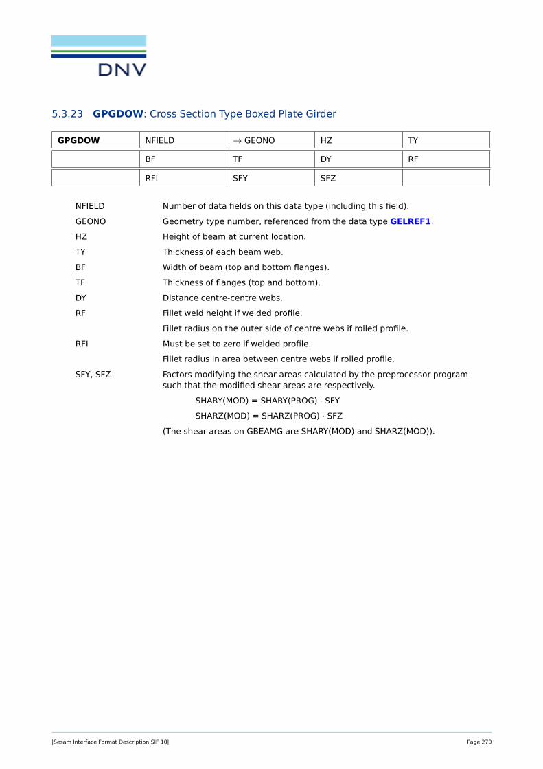
5.3.23 GPGDOW: Cross Section Type Boxed Plate Girder
GPGDOW NFIELD → GEONO HZ TY
BF TF DY RF
RFI SFY SFZ
NFIELD Number of data fields on this data type (including this field).
GEONO Geometry type number, referenced from the data type GELREF1.
HZ Height of beam at current location.
TY Thickness of each beam web.
BF Width of beam (top and bottom flanges).
TF Thickness of flanges (top and bottom).
DY Distance centre-centre webs.
RF Fillet weld height if welded profile.
Fillet radius on the outer side of centre webs if rolled profile.
RFI Must be set to zero if welded profile.
Fillet radius in area between centre webs if rolled profile.
SFY, SFZ Factors modifying the shear areas calculated by the preprocessor programsuch that the modified shear areas are respectively.
SHARY(MOD) = SHARY(PROG) · SFY
SHARZ(MOD) = SHARZ(PROG) · SFZ
(The shear areas on GBEAMG are SHARY(MOD) and SHARZ(MOD)).
|Sesam Interface Format Description|SIF 10| Page 270

Figure 5.14: Double web plate girder - welded case
Figure 5.15: Double web plate girder - rolled case
|Sesam Interface Format Description|SIF 10| Page 271

Back to Section 5.3 Nodal Data and Element Geometry Definition
|Sesam Interface Format Description|SIF 10| Page 272

5.3.24 GPIPE: Cross Section Type Tube
GPIPE → GEONO DI DY T
SFY SFZ NCIR NRAD
GEONO Geometry type number, referenced from the data type GELREF1.
DI Inner diameter of tube.
DY Outer diameter of tube (mandatory).
T Thickness of tube (not necessary if DI is given).
SFY, SFZ Factors modifying the shear areas calculated by the preprocessor programsuch that the modified shear areas are respectively
SHARY(MOD) = SHARY(PROG) · SFY
SHARZ(MOD) = SHARZ(PROG) · SFZ
(The shear areas on GBEAMG are SHARY(MOD) and SHARZ(MOD)).
NCIR, NRAD Number of integration points in circumferential and radial direction, respec-tively (optional).
Figure 5.16: Tube
Back to Section 5.3 Nodal Data and Element Geometry Definition
|Sesam Interface Format Description|SIF 10| Page 273

5.3.25 GSEPSPEC: Specified Separation Description
GSEPSPEC → SEPARID OPTION NDIST DISTANCE0
DISTANCE1 . . . DISTANCEn
The ’specified separation’ data type is a sub-type of the ’separation’ data type. Specified separation typemay also specify uniform separation type.
SEPARID Identification of the separation description. A unique integer value amongall the separation description data types (including all sub-types) in thesuper element. This number is referenced from the SEPARID number onthe GSLSTIFF data type.
OPTION Usage of DISTANCE0:
= 0 DISTANCE0 is not specified. Any value of DISTANCE0 is equallygood (not used).
= 1 DISTANCE0 is specified.
NDIST Number of different distances between stiffeners.
= 1 indicates that all separations are equal (uniform separation).
DISTANCE0 The distance to the first stiffener from the start of the plate. The start ofthe plate is the point on the plate which has the smallest y-values (usuallynegative), where y is in the local beam co-ordinate systems.
DISTANCEi The distance between stiffener number ’i’ and stiffener number ’i+ 1’. i ∈[1,NDIST]
For a uniform separation (DISTANCE0 is not specified), it will for a stiffener layer result in a smearing (multi-plication) factor (Fs) in the stiffener direction for Young’s modulus (E1). This factor is relative to a plate layerwith the same heigth as the stiffener layer.
The smearing (multiplication) factor Fs is given as
Fs =b
d1,
whereb = width of each stiffener.
d1 = DISTANCEi.
In the other direction, Young’s modulus (E2) will be taken equal to zero.
Back to Section 5.3 Nodal Data and Element Geometry Definition
|Sesam Interface Format Description|SIF 10| Page 274
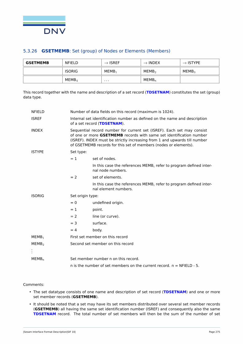
5.3.26 GSETMEMB: Set (group) of Nodes or Elements (Members)
GSETMEMB NFIELD → ISREF → INDEX → ISTYPE
ISORIG MEMB1 MEMB2 MEMB3
MEMB4 . . . MEMBn
This record together with the name and description of a set record (TDSETNAM) constitutes the set (group)data type.
NFIELD Number of data fields on this record (maximum is 1024).
ISREF Internal set identification number as defined on the name and descriptionof a set record (TDSETNAM).
INDEX Sequential record number for current set (ISREF). Each set may consistof one or more GSETMEMB records with same set identification number(ISREF). INDEX must be strictly increasing from 1 and upwards till numberof GSETMEMB records for this set of members (nodes or elements).
ISTYPE Set type:
= 1 set of nodes.
In this case the references MEMBi refer to program defined inter-nal node numbers.
= 2 set of elements.
In this case the references MEMBi refer to program defined inter-nal element numbers.
ISORIG Set origin type:
= 0 undefined origin.
= 1 point.
= 2 line (or curve).
= 3 surface.
= 4 body.
MEMB1 First set member on this record
MEMB2 Second set member on this record...
MEMBn Set member number n on this record.
n is the number of set members on the current record. n = NFIELD - 5.
Comments:
• The set datatype consists of one name and description of set record (TDSETNAM) and one or moreset member records (GSETMEMB).
• It should be noted that a set may have its set members distributed over several set member records(GSETMEMB) all having the same set identification number (ISREF) and consequently also the sameTDSETNAM record. The total number of set members will then be the sum of the number of set
|Sesam Interface Format Description|SIF 10| Page 275

members (n) for each of the set records.
Restrictions:
• Only one set type (ISTYPE) for same set identification number (ISREF) is allowed.
• If several records for the same set identification number (ISREF), record numbering must be strictlysequential:1 < INDEX < NINDEX, where NINDEX is the number of records per set.
• A set member (number) should only be included once in the list.
Back to Section 5.3 Nodal Data and Element Geometry Definition
|Sesam Interface Format Description|SIF 10| Page 276

5.3.27 GSLAYER: General Eccentric Sandwich Element
GSLAYER → GEONO NLAYER LAYERID1 LAYERID2
LAYERID3 . . . LAYERIDn
There are never more than one GSLAYER record for an element. The GSLAYER data type is referencedfrom the GELREF1 record for each element. When this layer ’stack’ record is referenced from the GELREF1data type, there is no need to refer to any material in the GELREF1 data type.
GEONO Geometry type number for this general sandwich (layered) element. Thegeometry type number is referenced from the data type GELREF1.
NLAYER Number of layers in the general eccentric sandwich (layered) element.
LAYERIDi Identification of layer no. ’i’. LAYERIDi refers to a GSLPLATE or GSLSTIFFrecord with identification LAYERIDi. It is a unique integer value among alllayers in the super element. i ∈ [1,NLAYER]
.
Back to Section 5.3 Nodal Data and Element Geometry Definition
|Sesam Interface Format Description|SIF 10| Page 277

5.3.28 GSLPLATE: Plate Layer Description
GSLPLATE → LAYERID MATNO SHFACT NECCNO
ECCNO1 . . . ECCNOn NTHICKID
THICKID1 . . . THICKIDn
The plate layer is a sub-type of layer. It identifies that the layer is a plate, i.e. shell element, and refer-ences possible eccentricities and mandatory element or element node thickness(es) of the plate.
LAYERID Identification of the layer. A unique integer value among all the layers inthe super element. This number is referenced from the LAYERID numberson the GSLAYER records.
MATNO Reference to the material.
SHFACT A factor for calculation of the shear deflection. A commonly used value forsquare cross sections and plates is 1.2.
NECCNO Number of eccentricity data for this layer (=1 or number of element nodes).
ECCNOi Reference to eccentricity description for the layer (=0 if there is no ec-centricity for this layer). ECCNOi refers to a GECC or GECCEN record.i ∈ [1,NECCNO]
.
NTHICKID Number of thickness data for this layer (=1 or number of element nodes).
THICKIDi Reference to the thickness for the plate or the plate nodes. THICKIDi refersto a GELTH record (in this case GEONO on the GELTH record should readTHICKIDi, since the GELREF1 record does not reference the GELTH recorddirectly for the general eccentric sandwich element). i ∈ [1,NTHICKID].
Back to Section 5.3 Nodal Data and Element Geometry Definition
|Sesam Interface Format Description|SIF 10| Page 278

5.3.29 GSLSTIFF: Stiffener Layer Description
GSLSTIFF → LAYERID MATNO SHFACT NECCNO
ECCNO1 . . . ECCNOn NSECTID
SECTID1 . . . SECTIDn SEPARID
ANGLE
The stiffener layer is a sub-type of layer. It identifies that this layer is a stiffener layer, i.e. beam elements,and specifies the additional information for the beams.
LAYERID Identification of the layer. A unique integer value among all the layers inthe super element. This number is referenced from the LAYERID numberson the GSLAYER records.
MATNO Reference to the material.
SHFACT A factor for calculation of the shear deflection. A commonly used value forsquare cross sections and plates is 1.2.
NECCNO Number of eccentricity data for this layer (=1 or number of element nodes).
ECCNOi Reference to eccentricity description for the layer (=0 if there is no ec-centricity for this layer). ECCNOi refers to a GECC or GECCEN record.i ∈ [1,NECCNO]
.
NSECTID Number of section references for this layer (=1 or number of elementnodes).
SECTIDi Reference to the section for the beam or the beam nodes. SECTIDi refers toa GBARM and a GBEAMG record (in this case GEONO on the GBARM andGBEAMG record should read SECTIDi, since the GELREF1 data type doesnot reference the GBARM and GBEAMG record directly for the generaleccentric sandwich element). i ∈ [1,NSECTID].
SEPARID Reference to the separation data description . The separation is the dis-tance between stiffeners in the plane of the element, but orthogonal to thestiffener direction.
ANGLE Angle with respect to the element’s reference direction (local x-axis). Theangle is specified in degrees. This angle and the local x-axis of the eccen-tric sandwich element determines the direction of the local x-axis of thestiffeners. The reference direction (local x-axis) of the eccentric sandwichelement are determined by the direction cosine matrix from the BNTR-COS data type, referenced on the GELREF1 record for this element. Thedirection determined from the first line of this direction cosine matrix is pro-jected down on the element plane and this gives the element’s referencedirection (local x-axis).
Back to Section 5.3 Nodal Data and Element Geometry Definition
|Sesam Interface Format Description|SIF 10| Page 279

5.3.30 GTONP: Cross Section T on Plate
GTONP → GEONO HZ TY BT
TT BP TP SFY
SFZ NLOBYT NLOBYB NLOBZ
GEONO Geometry type number, referenced from the data type GELREF1.
HZ Height of beam at current location.
TY Thickness of beam web.
BT Width of top flange.
TT Thickness of top flange.
BP Effective width of plate.
TP Thickness of plate.
SFY, SFZ Factors modifying the shear areas calculated by the preprocessor programsuch that the modified shear areas are respectively
SHARY(MOD) = SHARY(PROG) · SFY
SHARZ(MOD) = SHARZ(PROG) · SFZ
(The shear areas on GBEAMG are SHARY(MOD) and SHARZ(MOD)).
NLOBYT Number of integration points in top flange (optional).
NLOBYB Number of integration points in bottom plate (optional).
NLOBZ Number of integration points in beam web (optional).
Figure 5.17: I or H beam
Back to Section 5.3 Nodal Data and Element Geometry Definition
|Sesam Interface Format Description|SIF 10| Page 280

5.3.31 GUNIVEC: Specification of Local Element
GUNIVEC → TRANSNO UNIX UNIY UNIZ
TRANSNO Unit vector number, referenced from the data type GELREF1.
UNIX
UNIY Unit vector given in the super element co-ordinate system along the localz-axis (reference axis in the z-direction) of the element in the particularnode.
UNIZ
The GUNIVEC data type is used for beam elements only, i.e. basic element types 2, 15 and 23. Other basicelement types may refer to BNTRCOS data types. No ambiguity thus exists if both a GUNIVEC and a BN-TRCOS data type have same TRANSNO, but they should preferably have separate numbering (TRANSNO) toavoid possible program problems.
Back to Section 5.3 Nodal Data and Element Geometry Definition
|Sesam Interface Format Description|SIF 10| Page 281

5.3.32 GUSYI: Cross Section Type Unsymmetrical I-Beam
GUSYI → GEONO HZ TY BT
B1 TT BB B2
TB SFY SFZ NLOBYT
NLOBYB NLOBZ
GEONO Geometry type number, referenced from the data type GELREF1.
HZ Height of beam at current location.
TY Thickness of beam web.
BT Width of top flange.
B1 Width of half top flange in positive local y-direction.
TT Thickness of top flange.
BB Width of bottom flange.
B2 Width of half bottom flange in positive local y- direction
TB Thickness of bottom flange.
SFY, SFZ Factors modifying the shear areas calculated by the preprocessor programsuch that the modified shear areas are respectively
SHARY(MOD) = SHARY(PROG) · SFY
SHARZ(MOD) = SHARZ(PROG) · SFZ
(The shear areas on GBEAMG are SHARY(MOD) and SHARZ(MOD)).
NLOBYT Number of integration points in top flange (optional).
NLOBYB Number of integration points in bottom flange (optional).
NLOBZ Number of integration points in beam web (optional).
Figure 5.18: I or H beam
|Sesam Interface Format Description|SIF 10| Page 282

Back to Section 5.3 Nodal Data and Element Geometry Definition
|Sesam Interface Format Description|SIF 10| Page 283

5.4 Material Data
First level data
MAXDMP Axial Damper between Two Nodal Points see Section 5.4.1
MAXSPR Axial Spring between Two Nodal Points see Section 5.4.2
MCNT Material for Non-linear Contact Element see Section 5.4.3
MGDAMP Damping Element to Ground see Section 5.4.4
MGLDAMP General 2-noded Damping Element see Section 5.4.5
MGLMASS General 2-noded Mass Element see Section 5.4.6
MGMASS 1-Noded Mass element see Section 5.4.7
MGSPRNG Spring Element to Ground see Section 5.4.8
MISOAL Isotropy, Linear Acoustic Field Problem see Section 5.4.9
MISOEML Isotropy, Linear Electromagnetic Field Problem see Section 5.4.10
MISOHL Isotropy, Linear Heat Conduction Analysis see Section 5.4.11
MISOHNL Isotropy, Non-linear Heat Conduction Analysis see Section 5.4.12
MISOPL Non-linear Isotropic Material, Material Types 1-4 see Section 5.4.13
MISOPL Non-linear Isotropic Material for Grout, MaterialType 5
see Section 5.4.14
MISOPL Non-linear Isotropic Material for De-bonding Mate-rial, Material Type 6
see Section 5.4.15
MISOSEL Isotropy, Linear Elastic Structural Analysis see Section 5.4.16
MISTEL Temperature Dependent Isotropic, Linear ElasticMaterial
see Section 5.4.17
MORSMEL Anisotropy, Linear Elastic Structural Analysis, 2-DMembrane Elements and 2-D Thin Shell Elements
see Section 5.4.18
MORSSEL Anisotropy, Linear Elastic Structural Analysis, 3-DOne- and Multi-layered Thick Shell Elements
see Section 5.4.19
MORSSOL Anisotropy, Linear Elastic Structural Analysis, SolidElements
see Section 5.4.20
MSHGLSP General 2-noded Spring/Shim Element see Section 5.4.21
MTEMP Scaling Curve for Temperature Variation see Section 5.4.22
MTENONL Non-linear Material with Temperature Dependency see Section 5.4.23
MTRMEL Local Transformation of the Axes of An-isotropy,2-D Membrane Elements and 2-D Thin Shell Ele-ments
see Section 5.4.24
MTRSEL Local Transformation of the Axes of An-isotropy, 3-D Multi-layered Thick Shell Element
see Section 5.4.25
MTRSOL Local Transformation of the Axes of An-isotropy,Solid Elements
see Section 5.4.26
|Sesam Interface Format Description|SIF 10| Page 284

5.4.1 MAXDMP: Axial Damper between Two Nodal Points
MAXDMP → MATNO DAMP
MATNO Material number referred to in the element specification, see theGELMNT1 and GELREF1 data types.
DAMP Axial damping constant.
The axial damping constant corresponds to the force to be applied in order to get a unit velocity in thedirection of the basic element.
Back to Section 5.4 Material Data
|Sesam Interface Format Description|SIF 10| Page 285

5.4.2 MAXSPR: Axial Spring between Two Nodal Points
MAXSPR → MATNO SCON
MATNO Material number referred to in the element specification, see theGELMNT1 and GELREF1 data types.
SCON Axial spring constant.
The axial spring constant corresponds to the force to be applied in order to get a unit displacement in thedirection of the basic element.
Back to Section 5.4 Material Data
|Sesam Interface Format Description|SIF 10| Page 286

5.4.3 MCNT: Material for Non-linear Contact Element
MCNT → MATNO MATYP EMOD STIFAC
FRICOF
MATNO Material number referred to in the element specification, see theGELMNT1 and GELREF1 data types.
MATYP Contact surface behaviour.
= 1 Perfect sliding.
= 2 Perfect sticking.
= 3 Linear friction.
EMOD Typical Young’s modulus of surrounding elements.
STIFAC Factor that EMOD should be multiplied with to obtain contact stiffness.
Default: STIFAC = 105.
FRICOF Linear friction coefficient when MATYP = 3.
Back to Section 5.4 Material Data
|Sesam Interface Format Description|SIF 10| Page 287

5.4.4 MGDAMP: Damping Element to Ground
MGDAMP → MATNO NDOF C(1,1) C(2,1)
. . . . . . C(NDOF,1) C(2,2)
C(3,2) . . . . . . C(NDOF,2)
C(3,3) . . . . . . C(NDOF,NDOF)
MATNO Material number referred to in the element specification, see theGELMNT1 and GELREF1 data types.
NDOF Number of degrees of freedom at the node.
C(i,j) Elements of the damping matrix (only elements on and below the maindiagonal are stored, i.e. a symmetric damping matrix is assumed). Theelements are referred to a local co-ordinate system if defined (by TRANSNOon the GELREF1 data type), otherwise to the global co-ordinate system ofthe super element.
The damper to ground matrix is the viscous damping matrix.
Back to Section 5.4 Material Data
|Sesam Interface Format Description|SIF 10| Page 288

5.4.5 MGLDAMP: General 2-noded Damping Element
MGLDAMP → MATNO NDOF1 NDOF2
D(1,1) D(2,1) . . . D(NDOF1,1)
D(NDOF1+1,1) . . . D(TDOF,1) D(2,2)
D(3,2) . . . D(TDOF,2) D(3,3)
. . . D(TDOF,TDOF)
MATNO Material number referred to in the element specification, see theGELMNT1 and GELREF1 data types.
NDOF1 Number of degrees of freedom at local node 1.
NDOF2 Number of degrees of freedom at local node 2 .
D(i,j) Elements of the damping matrix (only elements on and below the maindiagonal are stored, i.e. a symmetric damping matrix is assumed). Theelements are referred to a local co-ordinate system if defined (by TRANSNOon the GELREF1 data type), otherwise to the global co-ordinate system ofthe super element.
(TDOF = NDOF1 + NDOF2).
The (i,j)’th element of the damping matrix D corresponds to the force to be given in the i’th degree offreedom in order to get a unit velocity in the j’th degree of freedom.
A GELMNT1 record with element type = 13 and a GELREF1 record with reference to this (MGLDAMP)record is necessary in order to fulfill the definition of the 2-noded damping element.
Back to Section 5.4 Material Data
|Sesam Interface Format Description|SIF 10| Page 289

5.4.6 MGLMASS: General 2-noded Mass Element
MGLMASS → MATNO NDOF1 NDOF2
M(1,1) M(2,1) . . . M(NDOF1,1)
M(NDOF1+1,1) . . . M(TDOF,1) M(2,2)
M(3,2) . . . M(TDOF,2) M(3,3)
. . . M(TDOF,TDOF)
MATNO Material number referred to in the element specification, see theGELMNT1 and GELREF1 data types.
NDOF1 Number of degrees of freedom at local node 1.
NDOF2 Number of degrees of freedom at local node 2 .
M(i,j) Elements of the mass matrix (only elements on and below the main diag-onal are stored, i.e. a symmetric mass matrix is assumed). The elementsare referred to a local co-ordinate system if defined (by TRANSNO on theGELREF1 data type), otherwise to the global co-ordinate system of thesuper element.
(TDOF = NDOF1 + NDOF2).
The (i,j)’th element of the mass matrix D corresponds to the force to be given in the i’th degree of freedomin order to get a unit accleration in the j’th degree of freedom.
A GELMNT1 record with element type = 13 and a GELREF1 record with reference to this (MGLMASS)record is necessary in order to fulfill the definition of the 2-noded mass element.
Back to Section 5.4 Material Data
|Sesam Interface Format Description|SIF 10| Page 290

5.4.7 MGMASS: 1-Noded Mass element
MGMASS → MATNO NDOF M(1,1) M(2,1)
. . . . . . M(NDOF,1) M(2,2)
M(3,2) . . . . . . M(NDOF,2)
M(3,3) . . . . . . M(NDOF,NDOF)
MATNO Material number referred to in the element specification, see theGELMNT1 and GELREF1 data types.
NDOF Number of degrees of freedom at the node.
M(i,j) Elements of the mass matrix (only elements on and below the main diago-nal are stored, i.e. a symmetric stiffness matrix is assumed). The elementsare referred to a local co-ordinate system if defined (by TRANSNO on theGELREF1 data type), otherwise to the global co-ordinate system of thesuper element.
Back to Section 5.4 Material Data
|Sesam Interface Format Description|SIF 10| Page 291

5.4.8 MGSPRNG: Spring Element to Ground
MGSPRNG → MATNO NDOF K(1,1) K(2,1)
. . . . . . K(NDOF,1) K(2,2)
K(3,2) . . . . . . K(NDOF,2)
K(3,3) . . . . . . K(NDOF,NDOF)
MATNO Material number referred to in the element specification, see theGELMNT1 and GELREF1 data types.
NDOF Number of degrees of freedom at the node.
K(i,j) Elements of the stiffness matrix (only elements on and below the maindiagonal are stored, i.e. a symmetric stiffness matrix is assumed). Theelements are referred to a local co-ordinate system if defined (by TRANSNOon the GELREF1 data type), otherwise to the global co-ordinate system ofthe super element.
The (i, j)’th element of the stiffness matrix corresponds to the force to be given in the i’th degree of freedomto get a unit displacement in the j’th degree of freedom.
Back to Section 5.4 Material Data
|Sesam Interface Format Description|SIF 10| Page 292

5.4.9 MISOAL: Isotropy, Linear Acoustic Field Problem
MISOAL → MATNO C CP CV
RHO PRESS TEMP R
MATNO Material number referred to in the element specification, see theGELMNT1 and GELREF1 data types.
C Speed of sound in gas.
CP Specific heat of gas at constant pressure.
CV Specific heat of gas at constant volume.
RHO Specific density of gas.
PRESS Gas pressure.
TEMP Gas temperature.
R Universal gas constant.
Back to Section 5.4 Material Data
|Sesam Interface Format Description|SIF 10| Page 293

5.4.10 MISOEML: Isotropy, Linear Electromagnetic Field Problem
MISOEML → MATNO PERM
MATNO Material number referred to in the element specification, see theGELMNT1 and GELREF1 data types.
PERM Permittivity.
Back to Section 5.4 Material Data
|Sesam Interface Format Description|SIF 10| Page 294

5.4.11 MISOHL: Isotropy, Linear Heat Conduction Analysis
MISOHL → MATNO RHO CHEAT COND
MATNO Material number referred to in the element specification, see theGELMNT1 and GELREF1 data types.
RHO Density.
CHEAT Specific heat.
COND Coefficient of heat conductivity.
Back to Section 5.4 Material Data
|Sesam Interface Format Description|SIF 10| Page 295

5.4.12 MISOHNL: Isotropy, Non-linear Heat Conduction Analysis
MISOHNL → MATNO RHO RTEMPNO CHEAT
CHTEMPNO COND COTEMPNO
MATNO Material number referred to in the element specification, see theGELMNT1 and GELREF1 data types.
RHO Density.
RTEMPNO Reference number to a temperature dependent scaling factor for RHO.
CHEAT Specific heat.
CHTEMPNO Reference number to a temperature dependent scaling factor for CHEAT.
COND Coefficient of heat conductivity.
COTEMPNO Reference number to a temperature dependent scaling factor for COND. Ifthere is no temperature dependence, the corresponding reference numberwill be zero.
Back to Section 5.4 Material Data
|Sesam Interface Format Description|SIF 10| Page 296

5.4.13 MISOPL: Non-linear Isotropic Material, Material Types 1-4
MISOPL → MATNO MATYP POISS RHO
DAMP ALPH B1 Not Used
NP SIG1 EPS1 SIG2
EPS2 . . . SIGNP EPSNP
MATNO Material number referred to in the element specification, see theGELMNT1 and GELREF1 data types.
MATYP Material type
= 1 Elasto-plastic material.
= 2 Non-linear hyperelastic material.
= 3 Overly technique.
= 4 Isotropic and kinematic hardening.
B1 Parameter for combining isotropic and kinematic hardening.
= 0.0 Isotropic.
= 1.0 Kinematic.
Any value between 0.0 and 1.0 is legal.
POISS Poisson’s ratio.
RHO Density.
DAMP Specific damping.
ALPH Thermal expansion coefficient.
B1 Only used for MATYP=4, see above and next page.
NP Number of points to represent the uniaxial stress-strain curve for increasedloading.
Note: NP < 30.
SIG1 Stress at the first point representing the stress-strain curve.
EPS1 Corresponding strain at the first point representing the stress-strain curve.
(YOUNG = SIG1/EPS1).
SIG2 Stress at the second point representing the stress-strain curve.
EPS2 Corresponding strain at the second point representing the stress-straincurve.
(YOUNG = SIG2/EPS2). See also Figure 5.19...
SIGNP Stress at the last point representing the stress-strain curve.
EPSNP Corresponding strain at the last point representing the stress-strain curve.
(YOUNG = SIGNP/EPSNP).
|Sesam Interface Format Description|SIF 10| Page 297

Not Used = 0. Notice that trailing blanks or zeros at the end of the data type to padthe line are not required.
Figure 5.19: Uniaxial stress-strain curve for increased loading
The material parameter B1 may be found from a one-dimensional loading-unloading curve with yielding:
Figure 5.20: Uniaxial stress-strain curve for increased loading
Back to Section 5.4 Material Data
|Sesam Interface Format Description|SIF 10| Page 298

5.4.14 MISOPL: Non-linear Isotropic Material for Grout, Material Type 5
MISOPL → MATNO MATYP POISS RHO
DAMP ALPH Not Used Not Used
NP SIG1 EPS1 FCM
Not Used Not Used Not Used EU
ET
MATNO Material number referred to in the element specification, see theGELMNT1 and GELREF1 data types.
MATYP Material type
= 5 Special theory for grout.
POISS Poisson’s ratio (recommended value 0.15 - 0.2).
RHO Density.
DAMP Specific damping.
ALPH Thermal expansion coefficient.
NP Number of points to represent the uniaxial stress-strain curve for increasedloading.
Note: NP = 1.
SIG1 Stress at the first point representing the stress-strain curve.
EPS1 Corresponding strain at the first point representing the stress-strain curve.
The relation YOUNG = SIG1/EPS1 is only used to compute Young’s modulus.
FCM Compression stress (concrete) at which the grout becomes perfectly plas-tic.
EU Compressive strain at crushing (uniaxial strain).
ET Tensile strain at cracking (uniaxial strain).
Not Used = 0. Notice that trailing blanks or zeros at the end of the data type to padthe line are not required.
Figure 5.21: Uniaxial stress-strain curve for grout
|Sesam Interface Format Description|SIF 10| Page 299

Back to Section 5.4 Material Data
|Sesam Interface Format Description|SIF 10| Page 300

5.4.15 MISOPL: Non-linear Isotropic Material for De-bonding Material, Material Type 6
MISOPL → MATNO MATYP POISS RHO
DAMP ALPH Not Used Not Used
NP SIG1 EPS1 SZMAX
TAUMAX EZREF GREF
MATNO Material number referred to in the element specification, see theGELMNT1 and GELREF1 data types.
MATYP Material type
= 5 Special theory for grout.
POISS Poisson’s ratio (recommended value 0.15 - 0.20).
RHO Density.
DAMP Specific damping.
ALPH Thermal expansion coefficient.
NP Number of points to represent the uniaxial stress-strain curve for increasedloading.
Note: NP = 1.
SIG1 Stress at the first point representing the stress-strain curve.
EPS1 Corresponding strain at the first point representing the stress-strain curve.
YOUNG = SIG1/EPS1. Recommended values: same as grout.
SZMAX Maximum tensile separation stress capacity.
TAUMAX Maximum shear capacity.
EZREF Reference strain, i.e. strain where total debonding takes place.
GREF Friction stiffness for closed gaps, (typical 0.5 times the shear modulus).
Not Used = 0. Notice that trailing blanks or zeros at the end of the data type to padthe line are not required.
|Sesam Interface Format Description|SIF 10| Page 301

Figure 5.22: a) Uniaxial stress-strain normal to steel surface, b) Maximum shear stress as function of normalstrain.
Back to Section 5.4 Material Data
|Sesam Interface Format Description|SIF 10| Page 302
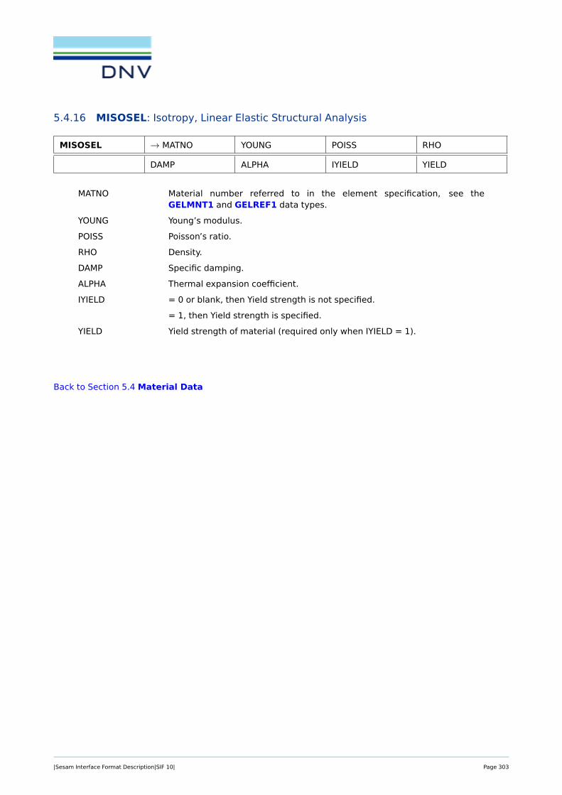
5.4.16 MISOSEL: Isotropy, Linear Elastic Structural Analysis
MISOSEL → MATNO YOUNG POISS RHO
DAMP ALPHA IYIELD YIELD
MATNO Material number referred to in the element specification, see theGELMNT1 and GELREF1 data types.
YOUNG Young’s modulus.
POISS Poisson’s ratio.
RHO Density.
DAMP Specific damping.
ALPHA Thermal expansion coefficient.
IYIELD = 0 or blank, then Yield strength is not specified.
= 1, then Yield strength is specified.
YIELD Yield strength of material (required only when IYIELD = 1).
Back to Section 5.4 Material Data
|Sesam Interface Format Description|SIF 10| Page 303
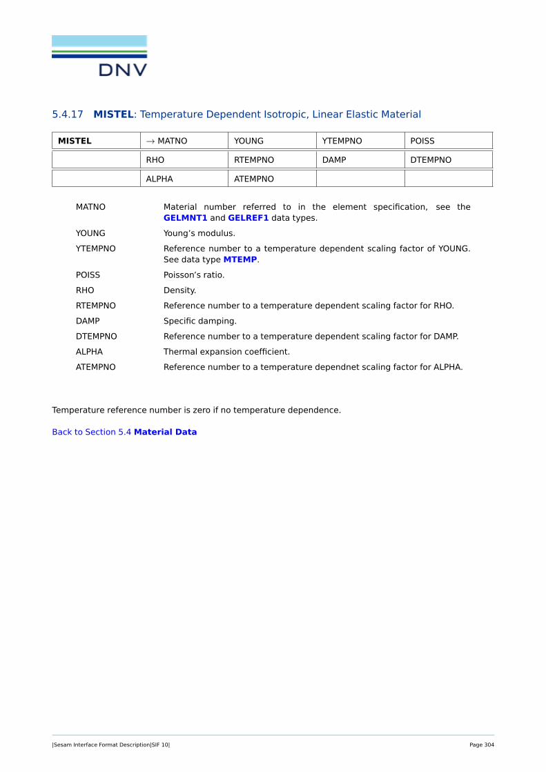
5.4.17 MISTEL: Temperature Dependent Isotropic, Linear Elastic Material
MISTEL → MATNO YOUNG YTEMPNO POISS
RHO RTEMPNO DAMP DTEMPNO
ALPHA ATEMPNO
MATNO Material number referred to in the element specification, see theGELMNT1 and GELREF1 data types.
YOUNG Young’s modulus.
YTEMPNO Reference number to a temperature dependent scaling factor of YOUNG.See data type MTEMP.
POISS Poisson’s ratio.
RHO Density.
RTEMPNO Reference number to a temperature dependent scaling factor for RHO.
DAMP Specific damping.
DTEMPNO Reference number to a temperature dependent scaling factor for DAMP.
ALPHA Thermal expansion coefficient.
ATEMPNO Reference number to a temperature dependnet scaling factor for ALPHA.
Temperature reference number is zero if no temperature dependence.
Back to Section 5.4 Material Data
|Sesam Interface Format Description|SIF 10| Page 304

5.4.18 MORSMEL: Anisotropy, Linear Elastic Structural Analysis, 2-D Membrane Ele-ments and 2-D Thin Shell Elements
MORSMEL → MATNO Q1 Q2 Q3
RHO D11 D21 D22
D31 D32 D33 PS1
PS2 DAMP1 DAMP2 ALPHA1
ALPHA2
MATNO Material number referred to in the element specification, see theGELMNT1 and GELREF1 data types.
Q1-Q3 Global components of a vector Q indicating axes of anisotropy. The firstprincipal axis of anisotropy is referred to the projection of Q on the mem-brane plane.
RHO Density.
D11-D33 Elements of the lower triangular part of the general anisotropic elasticitymatrix. In case of orthotropy, only D11, D21, D22 and D33 are nonzero.
PS1, PS2 Only given for plane strain situation. The stress normal to the membraneplane (σn) is calculated as follows: σn = PS1 · σ1 + PS2 · σ2.
(For an isotropic material PS1 and PS2 equal Poisson’s ratio)
DAMP1, DAMP2 Specific damping along respectively 1. and 2. principal axes of anisotropy.
ALPHA1, ALPHA2 Thermal expansion coefficients along respectively 1. and 2. principal axesof anisotropy.
Note: The vector Q must not be perpendicular to any of the elements.
Back to Section 5.4 Material Data
|Sesam Interface Format Description|SIF 10| Page 305

5.4.19 MORSSEL: Anisotropy, Linear Elastic Structural Analysis, 3-D One- and Multi-layered Thick Shell Elements
MORSSEL → MATNO Q1 Q2 Q3
RHO NLAY THL1 OANG1
D111 D1
21 D122 D1
31
D132 D1
33 D141 D1
42
D143 D1
44 D151 D1
52
D153 D1
54 D155 DAMP1
1
DAMP12 ALPHA1
1 ALPHA12 THL2
OANG2 D211 . . . . . .
THLNLAY . . . . . . ALPHANLAY2
MATNO Material number referred to in the element specification, see theGELMNT1 and GELREF1 data types.
Q1-Q3 Global components of a vector Q indicating axes of anisotropy. The firstprincipal axis of anisotropy is referred to the projection of Q on the mem-brane plane.
RHO Density.
NLAY = 1 One material type through the thickness.
≥ 2 Number of layers of a multilayered (sandwich) material.
THL1 Thickness of first layer in percent of element thickness. If NLAY = 1, THL1
is assumed equal to 100 (%).
OANG1 Angle in degrees giving rotation of the axes of anisotropy in the shell planefor material layer no. 1.
D111-D1
55 Elements of the lower triangular part of the general anisotropic elasticitymatrix for material layer no. 1.
In case of orthotropy, only the diagonal terms and D121 are nonzero.
D is defined by the relation in local layer axes:
σ = D · ε,where
ε = [εxx, εyy, γxy, γyz, γxz]T .
DAMP11, DAMP1
2 Specific damping along respectively 1. and 2. principal axes of anisotropyfor material no. 1.
ALPHA11, ALPHA1
2 Thermal expansion coefficients along respectively 1. and 2. principal axesof anisotropy.
THLi – ALPHAi2 are repeated for all i = 1, · · · ,NLAY layers of the sandwich material.
THL must add up to 100 (%).
|Sesam Interface Format Description|SIF 10| Page 306

Figure 5.23: 1. principal axis of anisotropy given by the global vector Q and a rotation angle a1 (OANG1) anda2 (OANG2) for a two-layered material.
For each integration point Q is projected on the shell surface and the same angle a is added. This impliesthat Q must not be perpendicular to the element surface in any of the integration points.
Back to Section 5.4 Material Data
|Sesam Interface Format Description|SIF 10| Page 307

5.4.20 MORSSOL: Anisotropy, Linear Elastic Structural Analysis, Solid Elements
MORSSOL → MATNO RHO D111 D1
21
D122 D1
31 D132 D1
33
D141 D1
42 D143 D1
44
D151 D1
52 D153 D1
54
D155 D1
61 D162 D1
63
D164 D1
65 D166 DAMP1
DAMP2 DAMP3 ALPHA1 ALPHA2
ALPHA3 TRANSO
MATNO Material number referred to in the element specification, see theGELMNT1 and GELREF1 data types.
RHO Density.
D11-D66 Elements of the lower triangular part of the general anisotropic elasticitymatrix.
In case of orthotropy, only the diagonal terms and D21, D31 D32 are nonzero.
D is defined by the relation in local layer axes:
σ = D · ε,where
ε = [εxx, εyy, εzz, γxy, γyz, γxz]T .
DAMP1, DAMP2,DAMP3
Specific damping along respectively 1. and 2. principal axes of anisotropyfor material no. 1.
ALPHA1, ALPHA2,ALPHA3
Thermal expansion coefficients along respectively 1. and 2. principal axesof anisotropy.
TRANSNO Reference number to the transformation to the anisotropy axes, defined ondata type BNTRCOS.
The transformation matrix is referred to the global co-ordinate system(Xanis = TXglob) and is common to all elements of this material type. Ad-ditional local rotation is defined on a record of data type MTRSOL for eachelement.
Back to Section 5.4 Material Data
|Sesam Interface Format Description|SIF 10| Page 308
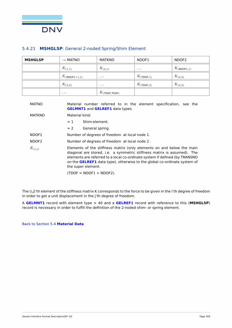
5.4.21 MSHGLSP: General 2-noded Spring/Shim Element
MSHGLSP → MATNO MATKND NDOF1 NDOF2
K(1,1) K(2,1) . . . K(NDOF1,1)
K(NDOF1+1,1) . . . K(TDOF,1) K(2,2)
K(3,2) . . . K(TDOF,2) K(3,3)
. . . K(TDOF,TDOF)
MATNO Material number referred to in the element specification, see theGELMNT1 and GELREF1 data types.
MATKND Material kind:
= 1 Shim-element.
= 2 General spring.
NDOF1 Number of degrees of freedom at local node 1.
NDOF2 Number of degrees of freedom at local node 2 .
K(i,j) Elements of the stiffness matrix (only elements on and below the maindiagonal are stored, i.e. a symmetric stiffness matrix is assumed). Theelements are referred to a local co-ordinate system if defined (by TRANSNOon the GELREF1 data type), otherwise to the global co-ordinate system ofthe super element.
(TDOF = NDOF1 + NDOF2).
The (i,j)’th element of the stiffness matrix K corresponds to the force to be given in the i’th degree of freedomin order to get a unit displacement in the j’th degree of freedom.
A GELMNT1 record with element type = 40 and a GELREF1 record with reference to this (MSHGLSP)record is necessary in order to fulfill the definition of the 2-noded shim- or spring element.
Back to Section 5.4 Material Data
|Sesam Interface Format Description|SIF 10| Page 309

5.4.22 MTEMP: Scaling Curve for Temperature Variation
MTEMP → TEMPNO NPOINT SCAL1 TEMP1
. . . . . . SCALNPOINT TEMPNPOINT
TEMPNO Temperature reference number of this curve.
NPOINT Number of points on this curve.
SCALi Scaling factor for point ’i’ on the curve.
TEMPi Temperature at point ’i’ on the curve.
Back to Section 5.4 Material Data
|Sesam Interface Format Description|SIF 10| Page 310

5.4.23 MTENONL: Non-linear Material with Temperature Dependency
MTENONL → MATNO MATYP POISS PTEMPNO
RHO RTEMPNO DAMP DTEMPNO
ALPHA ATEMPNO B1 Not Used
MTEMPNO YOUNG YTEMPNO NPOINT
SIG1 EPS1 SIG2 EPS2
. . . . . . SIGNPOINT EPSNPOINT
MATNO Material number referred to in the element specification, see theGELMNT1 and GELREF1 data types.
MATYP Material type
= 1 Elasto-plastic material.
= 2 Non-linear hyperelastic material.
= 3 Overly technique.
= 4 Isotropic and kinematic hardening.
B1 Parameter for combining isotropic and kinematic hardening.
= 0.0 Isotropic.
= 1.0 Kinematic.
Any value between 0.0 and 1.0 is legal.
= 5 Special theory for concrete.
POISS Reference Poisson’s ratio.
PTEMPNO Reference number to a temperature dependent scaling factor of POISS.
RHO Reference Density.
RTEMPNO Reference number to a temperature dependent scaling factor of RHO.
DAMP Specific damping.
DTEMPNO Reference number to a temperature dependent scaling factor of DAMP.
ALPHA Thermal expansion coefficient.
ATEMPNO Reference number to a temperature dependent scaling factor of ALPHA.
B1 Only used for MATYP=4, see above.
MTEMPNO Reference number to a temperature dependent scaling factor to the uniax-ial stress-strain curve.
YOUNG Number of points to represent the uniaxial stress-strain curve for increasedloading.
YTEMPNO Reference number to a temperature dependent scaling factor of YOUNG.
NPOINT Number of points to represent the uniaxial stress-strain curve for increasedloading.
SIG1 Stress at the first point representing the stress-strain curve.
|Sesam Interface Format Description|SIF 10| Page 311

EPS1 Corresponding strain at the first point representing the stress-strain curve.
(YOUNG = SIG1/EPS1).
SIG2 Stress at the second point representing the stress-strain curve.
EPS2 Corresponding strain at the second point representing the stress-straincurve.
(YOUNG = SIG1/EPS1)....
SIGNPOINT Stress at the last point representing the stress-strain curve.
EPSNPOINT Corresponding strain at the last point representing the stress-strain curve.
(YOUNG = SIGNPOINT/EPSNPOINT).
Not Used = 0. Notice that trailing blanks or zeros at the end of the data type to padthe line are not required.
Note:XTEMPNO (X = P, R, D, A or M) is given on record MTEMP.XTEMPNO = 0 means no temperature dependency of the actual parameter.
Back to Section 5.4 Material Data
|Sesam Interface Format Description|SIF 10| Page 312

5.4.24 MTRMEL: Local Transformation of the Axes of An-isotropy, 2-D Membrane Ele-ments and 2-D Thin Shell Elements
MTRMEL → ELNO OANG
ELNO Program defined internal number for the element.
OANG Angle in degrees giving local rotation of the axes of anisotropy in the el-ement plane (see Figure 5.24). OANG is referred to the projection of Qdefined on the material record of data type MORSMEL.
Figure 5.24: Axes of anisotropy (1, 2) given by Q (see material record of data type MORSMEL) and the anglea (OANG for a six-noded membrane in local co-ordinate system (x,y,z).
Back to Section 5.4 Material Data
|Sesam Interface Format Description|SIF 10| Page 313

5.4.25 MTRSEL: Local Transformation of the Axes of An-isotropy, 3-D Multi-layered ThickShell Element
MTRSEL → ELNO QROT NLAY OANG1
. . . OANGNLAY
ELNO Program defined internal number for the element.
QROT Additional rotation in degrees of all material layers of this element.
NLAY Number of layers of sandwich material.
If NLAY = 0, then OANGi for i ∈ [1, . . . ,NLAY] are assumed equal to zero.
If NLAY > 0, then OANGi for i ∈ [1, . . . ,NLAY] are explicitly given.
OANGi Additional rotation in the ("drilling") degree of material layer no. i.
This record is only read if MORSSEL records are given. If MTRSEL is not found for the actual element, nolocal rotation is assumed for this element.
Back to Section 5.4 Material Data
|Sesam Interface Format Description|SIF 10| Page 314

5.4.26 MTRSOL: Local Transformation of the Axes of An-isotropy, Solid Elements
MTRSOL → ELNO TRANS
ELNO Program defined internal number for the element.
TRANS Reference number to the transformation of the axes of anisotropy definedon data type BNTRCOS.
This transformation is added to the transformation defined on materialrecord MORSSOL,
i.e. XTRANS = T ·XTRANSNO.
This record is only read if MORSSOL records are given. If MTRSOL is not found for the actual element, nolocal transformation is assumed for this element.
Back to Section 5.4 Material Data
|Sesam Interface Format Description|SIF 10| Page 315

6 HIGHER LEVEL DATA
6.1 Additional Sub Element Data
Higher level data
ADDATA Additional User defined Sub Element Data see Section 6.1.1
AMATRIX Matrix control Data for Stiffness, Mass, Damping,Load and Resulting Displacement Matrix / Vector
see Section 6.1.2
AMDACCL Vector Data for Matrix Element Acceleration Vector see Section 6.1.3
AMDDAMP Matrix Data for Matrix Element Damping Matrix see Section 6.1.4
AMDDISP Vector Data for Matrix Element Displacement Vec-tor
see Section 6.1.5
AMDFREQ Frequency Definition for AMATRIX data types see Section 6.1.6
AMDLOAD Vector Data for Matrix Element Load Vector see Section 6.1.7
AMDMASS Matrix Data for Matrix Element Mass Matrix see Section 6.1.8
AMDSTIFF Matrix Data for Matrix Element Stiffness Matrix see Section 6.1.9
AMDVELO Vector Data for Matrix Element Velocity Vector see Section 6.1.10
|Sesam Interface Format Description|SIF 10| Page 316

6.1.1 ADDATA: Additional User defined Sub Element Data
ADDATA → ADDNO NPAR PAR(1) PAR(2)
. . . . . . PAR(NPAR)
ADDNO Additional data type number, i.e. reference number referring to additionaldata specifications.
NPAR Number of parameters specified by the user.
PAR(1)
PAR(2) Values for the different terms of the matrix input. The sequence is accord-ing to the convention of the analysis program. Relevant only if UNIT=0.
...
PAR(NPAR)
Whenever the analysis program requires data that are particular to a sub element of the super element typein question (and which are not defined elsewhere) this data type may be employed to assign the data.
The data assigned above are data intended for a lower level sub element. In the data type labelledGELMNT2 of the particular sub element an ADDNO must be included which corresponds with the ADDNOon the ADDATA data type.
The definition of the various parameters is depending on the analysis program to be used and must berevised when switching to another analysis program.
Back to Section 6.1 Additional Sub Element Data
|Sesam Interface Format Description|SIF 10| Page 317

6.1.2 AMATRIX: Matrix control Data for Stiffness, Mass, Damping, Load and ResultingDisplacement Matrix / Vector
AMATRIX NFIELD → MATNO Not Used NNOD
NSUB NODGEN Not Used Not Used
MATRTYP MATRREF MATRFORM IFREQ
MCOMPL Not Used Not Used Not Used
. . . . . . . . . . . .
. . . . . . . . . . . .
MATRTYP MATRREF MATRFORM IFREQ
MCOMPL
NFIELD Number of data fields on this data type (including this field and embeddednot used fields).
MATNO Reference number ("material number") for this AMATRIX data type.
NNOD Number of "normal" nodes on this element, not including possible gener-alised degrees of freedom (see description of NODGEN below) from e.g.component mode synthesis dynamic analysis. NNOD must correspond tospecification on the GELMNT1 data type.
NSUB No. of data fields in each sub-record (= 8 in present version of the AMA-TRIX data type).
NODGEN Number of nodes with generalised degrees of freedom. These extra"nodes" are counted after the "normal" nodes.
MATRTYP Matrix / vector type indicator:
= 1 Stiffness matrix
= 2 Damping matrix
= 3 Mass matrix
= 4 Load vector
= 5 Resulting Displacement vector
= 6 Resulting Velocity vector
= 7 Resulting Acceleration vector
MATRREF Matrix reference no. for the physical matrix. This no. is pointing to thereference MATRREF on the corresponding AMDSTIFF, AMDDAMP, AMD-MASS, AMDLOAD, AMDDISP, AMDVELO, AMDACCL and / or AMDFREQdata types. MATRREF is zero (0) if MATRFORM below is equal to -1.
MATRFORM = -1 Element result vectors (displacement, velocity or acceleration) arestored in Result File Format as described in "SIF, Results Interface File, FileDescription", ref [?].
= 0 Element vectors (load, displacement, velocity or acceleration) arestored.
|Sesam Interface Format Description|SIF 10| Page 318

= 1 Element matrix is symmetric and only upper triangle is stored. Forsub-matrices on the diagonal, all terms are stored and the diagonal sub-matrices must be symmetric.
= 2 Element matrix is diagonal and only the diagonal nodal matrices arestored. All terms within the nodal sub-matrices are stored, also terms beingzero.
= 3 Element matrix is non-symmetric and the full matrix is stored.
= 4 Element matrix is a null matrix, is uniquely defined and no elementsneed be stored. Hence: No storing of nodal matrices!
= 5 Element matrix is a unit matrix, is uniquely defined and no elementsneed be stored. Hence: No storing of nodal matrices!
IFREQ Additional attribute reference number for the matrix of type MATRTYP (e.g.frequency no. for which a stiffness, mass or damping matrix is valid). Thismeans that more than one matrix of same type may be stored for the sameelement. It is also possible that only one of the matrix types is e.g fre-quency dependent, while the other types are e.g. frequency independent(only one stiffness, mass and / or damping matrix stored). The correspon-dence between the frequency number and the frequency is stored on anAMDFREQ data type.
MCOMPL Indicator of matrix being real or complex.
= 0 Real values in matrix
= 1 Complex values in matrix
Not Used = 0. Notice that trailing blanks or zeros at the end of the data type to padthe line are not required.
The matrices are stored as sparse block data, which means that nodal matrices and / or vectors with allterms being zero are not stored.
The flag for load / displacement / velocity / acceleration vectors being real or complex are on each nodalvector data type AMDLOAD, AMDDISP and so on, since there may be a mixture of real and complex vec-tors.
A matrix element may only have one AMATRIX data type.
Back to Section 6.1 Additional Sub Element Data
|Sesam Interface Format Description|SIF 10| Page 319

6.1.3 AMDACCL: Vector Data for Matrix Element Acceleration Vector
AMDACCL NFIELD → MATRREF → MNODI → LLC
COMPLEX NDOF RACCL(1) RACCL(2)
. . . . . . . . . RACCL(NDOF)
IACCL(1) IACCL(2) . . . . . .
. . . IACCL(NDOF)
This data type contains acceleration terms for a nodal sub vector of an element (resulting) accelerationvector. It may be a "reduced" acceleration vector of a super element or an element acceleration vector of abasic element. Each record contains the acceleration terms of one node for one load case.
NFIELD Number of data fields on this data type (including this field and embeddednot used fields)..
MATRREF Reference number for this acceleration vector data type.
MNODI Local matrix element node number.
LLC Local acceleration vector number (positive integer number).
COMPLEX Phase shift definition.
= 0 no phase shift.
= 1 phase shift.
NDOF Number of degrees of freedom at the node MNODI.
RACCL(1) The real part of the acceleration vector with respect to the first degree offreedom at MNODI.
RACCL(2) The real part of the acceleration vector with respect to the second degreeof freedom at MNODI.
...
RACCL(NDOF) The real part of the acceleration vector with respect to the last degree offreedom at MNODI.
IACCL(1) The imaginary part of the acceleration vector with respect to the first de-gree of freedom at MNODI.
IACCL(2) The imaginary part of the acceleration vector with respect to the seconddegree of freedom at MNODI.
...
IACCL(NDOF) The imaginary part of the acceleration vector with respect to the last de-gree of freedom at MNODI.
The matrices / vectors are stored as sparse block data, which means that nodal matrices and / or vectorswith all terms being zero are not stored.
RACCL and IACCL refer to the transformed co-ordinate system if the node MNODI is transformed, else tothe global co-ordinate system of the super element.
|Sesam Interface Format Description|SIF 10| Page 320

The imaginary numbers follow immediately after the real numbers, i.e. there are no blank fields betweenthe last real number – RACCL(NDOF) – and the first imaginary number – IACCL(1). If no phase shift is specified(that is COMPLEX= 0), then the fields or positions IACCL(1), IACCL(2), etc. are left out.
Back to Section 6.1 Additional Sub Element Data
|Sesam Interface Format Description|SIF 10| Page 321

6.1.4 AMDDAMP: Matrix Data for Matrix Element Damping Matrix
AMDDAMP NFIELD → MATRREF → MNODI → MNODJ
CODDOF C(1,1) C(2,1) C(3,1)
C(4,1) . . . C(IDOF,1) C(1,2)
C(2,2) . . . C(IDOF,2) . . .
C(1,JDOF) . . . C(IDOF,JDOF)
This data type contains damping terms for a nodal sub matrix of an element damping matrix. It may bea "reduced" damping matrix of a super element or an element damping matrix of a basic element. Eachrecord contains the damping terms connecting one node with another, or with itself. For sub matrices onthe diagonal, all terms are always stored. Each AMDDAMP data type is indexed by the nodes which isconnected by the damping terms of the sub matrix.
NFIELD Number of data fields on this data type (including this field and embeddednot used fields)..
MATRREF Reference number for this damping matrix data type.
MNODI Local matrix element node number.
MNODJ Local matrix element node number.
CODDOF Coded form of sub matrix dimension:
CODDOF = IDOF*1000 + JDOF. The inverse relation will then be:
IDOF = integer part of (CODDOF/1000)
JDOF = remaindering of (CODDOF/1000)
IDOF = Number of degrees of freedom at the node MNODI.
JDOF = Number of degrees of freedom at the node MNODJ.
C(i,j) The (i, j)’th element of the damping matrix C.
If this is a complex damping matrix, the imaginary terms are stored after all the real terms.
The matrices are stored as sparse block data, which means that nodal matrices and / or vectors with allterms being zero are not stored.
Back to Section 6.1 Additional Sub Element Data
|Sesam Interface Format Description|SIF 10| Page 322

6.1.5 AMDDISP: Vector Data for Matrix Element Displacement Vector
AMDDISP NFIELD → MATRREF → MNODI → LLC
COMPLEX NDOF RDISP(1) RDISP(2)
. . . . . . . . . RDISP(NDOF)
IDISP(1) IDISP(2) . . . . . .
. . . IDISP(NDOF)
This data type contains displacement terms for a nodal sub vector of an element (resulting) displacementvector. It may be a "reduced" displacement vector of a super element or an element displacement vectorof a basic element. Each AMDDISP data type contains the displacement terms of one node for one loadcase.
NFIELD Number of data fields on this data type (including this field and embeddednot used fields)..
MATRREF Reference number for this displacement vector data type.
MNODI Local matrix element node number.
LLC Local displacement vector number (positive integer number).
COMPLEX Phase shift definition.
= 0 no phase shift.
= 1 phase shift.
NDOF Number of degrees of freedom at the node MNODI.
RDISP(1) The real part of the displacement vector with respect to the first degree offreedom at MNODI.
RDISP(2) The real part of the displacement vector with respect to the second degreeof freedom at MNODI.
...
RDISP(NDOF) The real part of the displacement vector with respect to the last degree offreedom at MNODI.
IDISP(1) The imaginary part of the displacement vector with respect to the first de-gree of freedom at MNODI.
IDISP(2) The imaginary part of the displacement vector with respect to the seconddegree of freedom at MNODI.
...
IDISP(NDOF) The imaginary part of the displacement vector with respect to the last de-gree of freedom at MNODI.
The matrices / vectors are stored as sparse block data, which means that nodal matrices and / or vectorswith all terms being zero are not stored.
RDISP and IDISP refer to the transformed co-ordinate system if the node MNODI is transformed, else tothe global co-ordinate system of the super element.
|Sesam Interface Format Description|SIF 10| Page 323

The imaginary numbers follow immediately after the real numbers, i.e. there are no blank fields betweenthe last real number – RDISP(NDOF) – and the first imaginary number – IDISP(1). If no phase shift is specified(that is COMPLEX= 0), then the fields or positions IDISP(1), IDISP(2), etc. are left out.
Back to Section 6.1 Additional Sub Element Data
|Sesam Interface Format Description|SIF 10| Page 324

6.1.6 AMDFREQ: Frequency Definition for AMATRIX data types
AMDFREQ NFIELD → MATRREF NFREQ Not Used
IFREQ(1) FREQ(1) IFREQ(2) FREQ(2)
. . . . . . IFREQ(NFREQ) FREQ(NFREQ)
This data type contains the frequencies referred to by the IFREQ field on the AMATRIX data type withthe same MATRREF as this data type.
NFIELD Number of data fields on this data type (including this field and embeddednot used fields)..
MATRREF Reference number for this frequency definition data type.
NFREQ Number of frequencies defined on this AMDFREQ data type.
IFREQ(1) The first frequency reference number.
FREQ(1) The frequency referred to by IFREQ(1) on the AMATRIX data type.
The dimension of the frequency is Herz (1/second), or in other words oscil-lations per second.
IFREQ(2) The second frequency reference number.
FREQ(2) The frequency referred to by IFREQ(2) on the AMATRIX data type....
IFREQ(NFREQ) The last frequency reference number.
FREQ(NFREQ) The frequency referred to by IFREQ(NFREQ) on the AMATRIX data type.
Not Used = 0. Notice that trailing blanks or zeros at the end of the data type to padthe line are not required.
All the IFREQ numbers referred to on the AMATRIX records must be defined on the AMDFREQ data type.
Back to Section 6.1 Additional Sub Element Data
|Sesam Interface Format Description|SIF 10| Page 325

6.1.7 AMDLOAD: Vector Data for Matrix Element Load Vector
AMDLOAD NFIELD → MATRREF → MNODI → LLC
COMPLEX NDOF RLOAD(1) RLOAD(2)
. . . . . . . . . RLOAD(NDOF)
ILOAD(1) ILOAD(2) . . . . . .
. . . ILOAD(NDOF)
This data type contains load terms for a nodal sub vector of an element load vector. It may be a "reduced"load vector of a super element or an element displacement vector of a basic element. Each AMDLOAD datatype contains the load terms of one node for one load case.
NFIELD Number of data fields on this data type (including this field and embeddednot used fields)..
MATRREF Reference number for this load vector data type.
MNODI Local matrix element node number.
LLC Local load vector number (positive integer number).
COMPLEX Phase shift definition.
= 0 no phase shift.
= 1 phase shift.
NDOF Number of degrees of freedom at the node MNODI.
RLOAD(1) The real part of the load vector with respect to the first degree of freedomat MNODI.
RLOAD(2) The real part of the load vector with respect to the second degree of free-dom at MNODI.
...
RLOAD(NDOF) The real part of the load vector with respect to the last degree of freedomat MNODI.
ILOAD(1) The imaginary part of the load vector with respect to the first degree offreedom at MNODI.
ILOAD(2) The imaginary part of the load vector with respect to the second degree offreedom at MNODI.
...
ILOAD(NDOF) The imaginary part of the load vector with respect to the last degree offreedom at MNODI.
The matrices / vectors are stored as sparse block data, which means that nodal matrices and / or vectorswith all terms being zero are not stored.
RLOAD and ILOAD refer to the transformed co-ordinate system if the node MNODI is transformed, else tothe global co-ordinate system of the super element.
|Sesam Interface Format Description|SIF 10| Page 326

The imaginary numbers follow immediately after the real numbers, i.e. there are no blank fields betweenthe last real number – RLOAD(NDOF) – and the first imaginary number – ILOAD(1). If no phase shift is specified(that is COMPLEX= 0), then the fields or positions ILOAD(1), ILOAD(2), etc. are left out.
Back to Section 6.1 Additional Sub Element Data
|Sesam Interface Format Description|SIF 10| Page 327

6.1.8 AMDMASS: Matrix Data for Matrix Element Mass Matrix
AMDMASS NFIELD → MATRREF → MNODI → MNODJ
CODDOF M(1,1) M(2,1) M(3,1)
M(4,1) . . . M(IDOF,1) M(1,2)
M(2,2) . . . M(IDOF,2) . . .
M(1,JDOF ) . . . M(IDOF,JDOF )
This data type contains mass terms for a nodal sub matrix of an element mass matrix. It may be a "re-duced" mass matrix of a super element or an element mass matrix of a basic element. Each data typecontains the mass terms connecting one node with another, or with itself. For sub matrices on the diagonal,all terms are always stored. Each data type of this type is indexed by the nodes which is connected by themass terms of the sub matrix.
NFIELD Number of data fields on this data type (including this field and embeddednot used fields)..
MATRREF Reference number for this mass matrix data type.
MNODI Local matrix element node number.
MNODJ Local matrix element node number.
CODDOF Coded form of sub matrix dimension:
CODDOF = IDOF*1000 + JDOF. The inverse relation will then be:
IDOF = integer part of (CODDOF/1000)
JDOF = remaindering of (CODDOF/1000)
IDOF = Number of degrees of freedom at the node MNODI.
JDOF = Number of degrees of freedom at the node MNODJ.
M(i,j) The (i, j)’th element of the mass matrix M .
If this is a complex mass matrix, the imaginary terms are stored after all the real terms.
The matrices are stored as sparse block data, which means that nodal matrices and / or vectors with allterms being zero are not stored.
Back to Section 6.1 Additional Sub Element Data
|Sesam Interface Format Description|SIF 10| Page 328

6.1.9 AMDSTIFF: Matrix Data for Matrix Element Stiffness Matrix
AMDSTIFF NFIELD → MATRREF → MNODI → MNODJ
CODDOF K(1,1) K(2,1) K(3,1)
K(4,1) . . . K(IDOF,1) K(1,2)
K(2,2) . . . K(IDOF,2) . . .
K(1,JDOF ) . . . K(IDOF,JDOF )
This data type contains stiffness terms for a nodal sub matrix of an element stiffness matrix. It may bea "reduced" stiffness matrix of a super element or an element stiffness matrix of a basic element. Each datatype contains the stiffness terms connecting one node with another, or with itself. For sub matrices on thediagonal, all terms are always stored. Each data type of this type is indexed by the nodes which is connectedby the stiffness terms of the sub matrix.
NFIELD Number of data fields on this data type (including this field and embeddednot used fields)..
MATRREF Reference number for this stiffness matrix data type.
MNODI Local matrix element node number.
MNODJ Local matrix element node number.
CODDOF Coded form of sub matrix dimension:
CODDOF = IDOF*1000 + JDOF. The inverse relation will then be:
IDOF = integer part of (CODDOF/1000)
JDOF = remaindering of (CODDOF/1000)
IDOF = Number of degrees of freedom at the node MNODI.
JDOF = Number of degrees of freedom at the node MNODJ.
K(i,j) The (i, j)’th element of the stiffness matrix K.
If this is a complex stiffness matrix, the imaginary terms are stored after all the real terms.
The matrices are stored as sparse block data, which means that nodal matrices and / or vectors with allterms being zero are not stored.
Back to Section 6.1 Additional Sub Element Data
|Sesam Interface Format Description|SIF 10| Page 329

6.1.10 AMDVELO: Vector Data for Matrix Element Velocity Vector
AMDVELO NFIELD → MATRREF → MNODI → LLC
COMPLEX NDOF RVELO(1) RVELO(2)
. . . . . . . . . RVELO(NDOF)
IVELO(1) IVELO(2) . . . . . .
. . . IVELO(NDOF)
This data type contains velocity terms for a nodal sub vector of an element (resulting) velocity vector. Itmay be a "reduced" velocity vector of a super element or an element velocity vector of a basic element.Each data type contains the velocity terms of one node for one load case.
NFIELD Number of data fields on this data type (including this field and embeddednot used fields)..
MATRREF Reference number for this velocity vector data type.
MNODI Local matrix element node number.
LLC Local velocity vector number (positive integer number).
COMPLEX Phase shift definition.
= 0 no phase shift.
= 1 phase shift.
NDOF Number of degrees of freedom at the node MNODI.
RVELO(1) The real part of the velocity vector with respect to the first degree of free-dom at MNODI.
RVELO(2) The real part of the velocity vector with respect to the second degree offreedom at MNODI.
...
RVELO(NDOF) The real part of the velocity vector with respect to the last degree of free-dom at MNODI.
IVELO(1) The imaginary part of the velocity vector with respect to the first degree offreedom at MNODI.
IVELO(2) The imaginary part of the velocity vector with respect to the second degreeof freedom at MNODI.
...
IVELO(NDOF) The imaginary part of the velocity vector with respect to the last degree offreedom at MNODI.
The matrices / vectors are stored as sparse block data, which means that nodal matrices and / or vectorswith all terms being zero are not stored.
RVELO and IVELO refer to the transformed co-ordinate system if the node MNODI is transformed, else tothe global co-ordinate system of the super element.
|Sesam Interface Format Description|SIF 10| Page 330

The imaginary numbers follow immediately after the real numbers, i.e. there are no blank fields betweenthe last real number – RVELO(NDOF) – and the first imaginary number – IVELO(1). If no phase shift is specified(that is COMPLEX= 0), then the fields or positions IVELO(1), IVELO(2), etc. are left out.
Back to Section 6.1 Additional Sub Element Data
|Sesam Interface Format Description|SIF 10| Page 331

6.2 Boundary Conditions, Loads and Point Masses
Higher level data
BLDEP Node with Linear Dependency see Section 6.2.1
BNBCD Node with Boundary Condition see Section 6.2.2
BNDISPL Node with Displacement, Velocity and/or Accelera-tion
see Section 6.2.3
BNDOF Node with Transformation see Section 6.2.4
BNINCO Node with Initial Condition If Arbitrary Time Depen-dent Loading
see Section 6.2.5
BNLOAD Node with Load see Section 6.2.6
BNMASS Node with Point Mass see Section 6.2.7
BNTRCOS Transformation from Global to Local Co-ordinateSystem, Direction Cosines
see Section 6.2.8
BQDP Node with Simple Quadratic Dependence see Section 6.2.9
BSELL Sub Element Load Description see Section 6.2.10
|Sesam Interface Format Description|SIF 10| Page 332
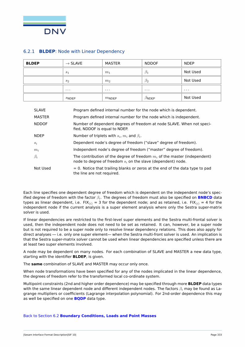
6.2.1 BLDEP: Node with Linear Dependency
BLDEP → SLAVE MASTER NDDOF NDEP
s1 m1 β1 Not Used
s2 m2 β2 Not Used
. . . . . . . . . . . .
sNDEP mNDEP βNDEP Not Used
SLAVE Program defined internal number for the node which is dependent.
MASTER Program defined internal number for the node which is independent.
NDDOF Number of dependent degrees of freedom at node SLAVE. When not speci-fied, NDDOF is equal to NDEP.
NDEP Number of triplets with si, mi and βi.
si Dependent node’s degree of freedom (“slave” degree of freedom).
mi Independent node’s degree of freedom (“master” degree of freedom).
βi The contribution of the degree of freedom mi of the master (independent)node to degree of freedom si on the slave (dependent) node.
Not Used = 0. Notice that trailing blanks or zeros at the end of the data type to padthe line are not required.
Each line specifies one dependent degree of freedom which is dependent on the independent node’s spec-ified degree of freedom with the factor βi. The degrees of freedom must also be specified on BNBCD datatypes as linear dependent, i.e. FIX(i) = 3 for the dependent node; and as retained, i.e. FIX(i) = 4 for theindependent node if the current analysis is a super element analysis where only the Sestra super-matrixsolver is used.
If linear dependencies are restricted to the first-level super elements and the Sestra multi-frontal solver isused, then the independent node does not need to be set as retained. It can, however, be a super nodebut is not required to be a super node only to resolve linear dependency relations. This does also apply fordirect analyses — i.e. only one super element— when the Sestra multi-front solver is used. An implication isthat the Sestra super-matrix solver cannot be used when linear dependencies are specified unless there areat least two super elements involved.
A node may be dependent on many nodes. For each combination of SLAVE and MASTER a new data type,starting with the identifier BLDEP, is given.
The same combination of SLAVE and MASTER may occur only once.
When node transformations have been specified for any of the nodes implicated in the linear dependence,the degrees of freedom refer to the transformed local co-ordinate system.
Multipoint constraints (2nd and higher order dependence) may be specified through more BLDEP data typeswith the same linear dependent node and different independent nodes. The factors βi may be found as La-grange multipliers or coefficients (Lagrange interpolation polynomial). For 2nd-order dependence this mayas well be specified on one BQDP data type.
Back to Section 6.2 Boundary Conditions, Loads and Point Masses
|Sesam Interface Format Description|SIF 10| Page 333

6.2.2 BNBCD: Node with Boundary Condition
BNBCD → NODENO NDOF FIX(1) FIX(2)
. . . . . . . . . FIX(NDOF)
NODENO Program defined internal number for the node with specified boundary con-dition.
NDOF Number of degrees of freedom at the node NODENO.
FIX(1)
FIX(2)
... Specification of boundary condition codes for the relevant degrees of free-dom.
FIX(NDOF)
The following boundary condition codes, i.e. the values for FIX(1), FIX(2), . . . , FIX(NDOF) - are defined for thestatus of the degrees of freedom:
FIX(i) = 0 no boundary condition is applied to the degree of freedom.
FIX(i) = 1 fixed at zero displacement, temperature, etc.
FIX(i) = 2 prescribed displacement, temperature, velocity, acceleration, etc. differ-ent from zero.
FIX(i) = 3 linearly dependent.
FIX(i) = 4 retained degree of freedom, i.e. super node.
The code FIX(i) = 2 just indicates specified condition for the relevant degree of freedom. Whether it is dis-placement, first time derivative of the displacement etc. is defined on the BNDISPL data type.
Degrees of freedom with FIX(i) = 2 which are not defined on the BNDISPL data type will be fixed (havezero displacement, velocity and acceleration).
The node numbers (degrees of freedom) with FIX(i) = 4 are called super nodes. The super node num-bering is according to the increasing order of their internal node number.
Back to Section 6.2 Boundary Conditions, Loads and Point Masses
|Sesam Interface Format Description|SIF 10| Page 334

6.2.3 BNDISPL: Node with Displacement, Velocity and/or Acceleration
BNDISPL → LLC DTYPE COMPLEX Not Used
→ NODENO NDOF RDISP(1) RDISP(2)
. . . . . . . . . RDISP(NDOF)
IDISP(1) IDISP(2) . . . . . .
. . . IDISP(NDOF)
LLC Local load case number (positive integer number).
DTYPE Type of boundary condition.
= 1 specified displacement, temperature, etc.
= 2 specified velocity, first time derivative of the temperature, etc.
= 3 specified acceleration, etc.
COMPLEX Phase shift definition.
= 0 no phase shift.
= 1 phase shift.
NODENO Program defined internal number for the node with specified boundary con-dition.
NDOF Number of degrees of freedom at the node NODENO.
RDISP(1) The real part of the specified boundary condition with respect to the firstdegree of freedom at NODENO.
RDISP(2) The real part of the specified boundary condition with respect to the seconddegree of freedom at NODENO.
...
RDISP(NDOF) The real part of the specified boundary condition with respect to the lastdegree of freedom at NODENO.
IDISP(1) The imaginary part of the specified boundary condition with respect to thefirst degree of freedom at NODENO.
IDISP(2) The imaginary part of the specified boundary condition with respect to thesecond degree of freedom at NODENO.
...
IDISP(NDOF) The imaginary part of the specified boundary condition with respect to thelast degree of freedom at NODENO.
Not Used = 0. Notice that trailing blanks or zeros at the end of the data type to padthe line are not required.
RDISP and IDISP refer to the transformed co-ordinate system if the node NODENO is transformed, else to theglobal co-ordinate system of the super element.
The imaginary numbers follow immediately after the real numbers, i.e. there are no blank fields betweenthe last real number – RDISP(NDOF) – and the first imaginary number – IDISP(1). If no phase shift is specified
|Sesam Interface Format Description|SIF 10| Page 335

(that is COMPLEX= 0), then the fields or positions IDISP(1), IDISP(2), etc. are left out.
Back to Section 6.2 Boundary Conditions, Loads and Point Masses
|Sesam Interface Format Description|SIF 10| Page 336

6.2.4 BNDOF: Node with Transformation
BNDOF → NODENO TRANSD TRANSR
NODENO Program defined internal number for the node with transformation.
TRANSD Reference number to the transformed co-ordinate system of the displace-ments, given on BNTRCOS for NODENO.
TRANSR Reference number to the transformed co-ordinate system of the rotations,given on BNTRCOS for NODENO.
If no reference number is given, no transformation is relevant to the relevant type of degree of freedom, i.e.translations or rotations for NODENO.
Back to Section 6.2 Boundary Conditions, Loads and Point Masses
|Sesam Interface Format Description|SIF 10| Page 337

6.2.5 BNINCO: Node with Initial Condition If Arbitrary Time Dependent Loading
BNINCO → INCONO DTYPE Not Used Not Used
→ NODENO NDOF RVALUE(1) RVALUE(2)
. . . . . . . . . RVALUE(NDOF)
INCONO Initial condition number.
DTYPE Type of initial condition.
= 1 displacement.
= 2 velocity.
Both initial displacements and velocities may be specified for a node, butthen on separate BNINCO data types.
NODENO Program defined internal number for the node with initial condition.
NDOF Number of degrees of freedom at the node NODENO.
RVALUE(1) The initial condition with respect to the first degree of freedom at NODENO.
RVALUE(2) The initial condition with respect to the second degree of freedom atNODENO.
...
RVALUE(NDOF) The initial condition with respect to the last degree of freedom at NODENO.
Not Used = 0. Notice that trailing blanks or zeros at the end of the data type to padthe line are not required.
Back to Section 6.2 Boundary Conditions, Loads and Point Masses
|Sesam Interface Format Description|SIF 10| Page 338

6.2.6 BNLOAD: Node with Load
BNLOAD → LLC LOTYP COMPLEX Not Used
→ NODENO NDOF RLOAD(1) RLOAD(2)
. . . . . . . . . RLOAD(NDOF)
ILOAD(1) ILOAD(2) . . . . . .
. . . ILOAD(NDOF)
LLC Local load case number (positive integer number).
LOTYP Type of load at the node NODENO.
= 0 not decided whether conservative or non-conservative load.
= 1 conservative load.
= -1 non-conservative load.
COMPLEX Phase shift definition.
= 0 no phase shift.
= 1 phase shift.
NODENO Program defined internal number for the node with load condition.
NDOF Number of degrees of freedom at the node NODENO.
RLOAD(1) The real part of the load condition with respect to the first degree of free-dom at NODENO.
RLOAD(2) The real part of the load condition with respect to the second degree offreedom at NODENO.
...
RLOAD(NDOF) The real part of the load condition with respect to the last degree of free-dom at NODENO.
ILOAD(1) The imaginary part of the load condition with respect to the first degree offreedom at NODENO.
ILOAD(2) The imaginary part of the load condition with respect to the second degreeof freedom at NODENO.
...
ILOAD(NDOF) The imaginary part of the load condition with respect to the last degree offreedom at NODENO.
Not Used = 0. Notice that trailing blanks or zeros at the end of the data type topad the line are not required.
The imaginary numbers follow immediately after the real numbers, i.e. there are no blank fields betweenthe last real number – RLOAD(NDOF) – and the first imaginary number – ILOAD(1). If no phase shift is specified(that is COMPLEX= 0), then the fields or positions ILOAD(1), ILOAD(2), etc. are left out.
Back to Section 6.2 Boundary Conditions, Loads and Point Masses
|Sesam Interface Format Description|SIF 10| Page 339

6.2.7 BNMASS: Node with Point Mass
BNMASS → NODENO NDOF MASS(1) MASS(2)
. . . . . . . . . MASS(NDOF)
ModelNode
NODENO Program defined internal number for the node with point mass.
NDOF Number of degrees of freedom at the node NODENO.
MASS(1) The point mass with respect to the first degree of freedom at NODENO.
MASS(2) The point mass with respect to the second degree of freedom at NODENO....
MASS(NDOF) The point mass with respect to the last degree of freedom at NODENO.
ModelNode If ModelNode > 0, then it represents the super element assembly origin,or part of the original super element model. That is, ModelNode is equalto the unique tree node identifier created when super element models areassembled to global models for direct analysis in Sestra. If ModelNode ≤0 it means that the data applies for the whole assembled model. For theBNMASS datatype ModelNode is optional. If ModelNode is not given thedata applies for the whole model.
The point mass contributions in MASS(i) refer to the transformed co-ordinate system if the node NODENO istransformed, else to the global co-ordinate system of the super element.
A more general method for specifying mass is the mass element GMAS(Sesam element type number 11),specified with the GELMNT1 and the MGMASS data type.
Back to Section 6.2 Boundary Conditions, Loads and Point Masses
|Sesam Interface Format Description|SIF 10| Page 340

6.2.8 BNTRCOS: Transformation from Global to Local Co-ordinate System, Direction Cosines
BNTRCOS → TRANSNO c1,1 c2,1 c3,1
c1,2 c2,2 c3,2 c1,3
c2,3 c3,3
TRANSNO Reference number to the transformed co-ordinate system.
c1,1
c2,1
c3,1
c1,2
c2,2 Terms (9 direction cosines) of the transformation matrix C.
c3,2
c1,3
c2,3
c3,3
The transformation matrix C describes the transformation defined by
r′ = Cr (6.1)
where r′ refers to the local co-ordinate system and r to the global (super element) co-ordinate system.
C is applied to both translations and rotations.
For 2D models all 9 values should be given and the program reading the data type must extract the val-ues c1,1, c2,1, c1,2 and c2,2 from this matrix.
The GUNIVEC data types are used for beam elements only, i.e. basic element types 2, 15 and 23. Otherbasic element types may refer to BNTRCOS data types. No ambiguity thus exists if both a GUNIVEC andBNTRCOS data type have same TRANSNO, but they should preferably have separate numbering (TRANSNO)to avoid possible program problems.
Back to Section 6.2 Boundary Conditions, Loads and Point Masses
|Sesam Interface Format Description|SIF 10| Page 341

6.2.9 BQDP: Node with Simple Quadratic Dependence
BQDP → NODENO DDOF Not Used Not Used
CNOD(1) δ(1,1) β(1,1) δ(1,2)
β(1,2) . . . . . . δ(1,DDOF)
β(1,DDOF) Not Used Not Used Not Used
CNOD(2) δ(2,1) β(2,1) δ(2,2)
β(2,2) . . . . . . δ(2,DDOF)
β(2,DDOF) Not Used Not Used Not Used
...
CNOD(N) δ(N,1) β(N,1) δ(N,2)
β(N,2) . . . . . . δ(N,DDOF)
β(N,DDOF)
NODENO Program defined internal number for the node with dependency.
DDOF Number of dependent degrees of freedom at the node NODENO. (Must cor-respond with the number of degrees of freedom with the code FIX = 3referenced in BNBCD for NODENO.)
CNOD(1) Program defined internal node number for the first independent node.
δ(1,1) The first relevant independent degree of freedom at CNOD(1) which is cou-pled to the corresponding dependent degree of freedom at NODENO.
β(1,1) The corresponding contribution of the first relevant degree of freedom atCNOD(1) to the quadratic dependence of the corresponding dependent de-gree of freedom at NODENO.
δ(1,2) The second relevant independent degree of freedom at CNOD(1) which iscoupled to the corresponding dependent degree of freedom at NODENO.
β(1,2) The corresponding contribution of the second relevant degree of freedomat CNOD(1) to the quadratic dependence of the corresponding dependentdegree of freedom at NODENO.
...
δ(1,DDOF) The number DDOF relevant independent degree of freedom at CNOD(1)
which is coupled to the corresponding dependent degree of freedom atNODENO.
β(1,DDOF) The corresponding contribution of the DDOF relevant degree of freedomat CNOD(1) to the quadratic dependence of the corresponding dependentdegree of freedom at NODENO.
CNOD(2) Program defined internal node number for the second independent node.
δ(2,1) The first relevant independent degree of freedom at CNOD(2) which is cou-pled to the corresponding dependent degree of freedom at NODENO.
β(2,1) The corresponding contribution of the first relevant degree of freedom atCNOD(2) to the quadratic dependence of the corresponding dependent de-gree of freedom at NODENO.
|Sesam Interface Format Description|SIF 10| Page 342

δ(2,2) The second relevant independent degree of freedom at CNOD(2) which iscoupled to the corresponding dependent degree of freedom at NODENO.
β(2,2) The corresponding contribution of the second relevant degree of freedomat CNOD(1) to the quadratic dependence of the corresponding dependentdegree of freedom at NODENO.
...
δ(2,DDOF) The number DDOF relevant independent degree of freedom at CNOD(2)
which is coupled to the corresponding dependent degree of freedom atNODENO.
β(2,DDOF) The corresponding contribution of the DDOF relevant degree of freedomat CNOD(2) to the quadratic dependence of the corresponding dependentdegree of freedom at NODENO.
...
...
CNOD(N) Program defined internal node number for the last independent node - thatis independent node N.
δ(N,1) The first relevant independent degree of freedom at CNOD(N) which is cou-pled to the corresponding dependent degree of freedom at NODENO.
β(N,1) The corresponding contribution of the first relevant degree of freedom atCNOD(N) to the quadratic dependence of the corresponding dependent de-gree of freedom at NODENO.
δ(N,2) The second relevant independent degree of freedom at CNOD(N) which iscoupled to the corresponding dependent degree of freedom at NODENO.
β(N,2) The corresponding contribution of the second relevant degree of freedomat CNOD(N) to the quadratic dependence of the corresponding dependentdegree of freedom at NODENO.
...
δ(N,DDOF) The number DDOF relevant independent degree of freedom at CNOD(N)
which is coupled to the corresponding dependent degree of freedom atNODENO.
β(N,DDOF) The corresponding contribution of the DDOF relevant degree of freedomat CNOD(N) to the quadratic dependence of the corresponding dependentdegree of freedom at NODENO.
Not Used = 0. Notice that trailing blanks or zeros at the end of the data type to padthe line are not required.
N is the number of independent nodes that NODENO is dependent on.
By simple is meant that f.ex. the first dependent degree of freedom is always coupled to the first inde-pendent degree of freedom, the second dependent degree of freedom is always coupled to the secondindependent degree of freedom, etc.
Note: This data type is not available in Sesam.
|Sesam Interface Format Description|SIF 10| Page 343

Back to Section 6.2 Boundary Conditions, Loads and Point Masses
|Sesam Interface Format Description|SIF 10| Page 344

6.2.10 BSELL: Sub Element Load Description
BSELL → LC → SUBNO Not Used Not Used
LLC(1) FACT(1) LLC(2) FACT(2)
. . . . . . LLC(NLOAD) FACT(NLOAD)
LC Global load case number (positive integer number).
SUBNO Sub element number of the super element in question.
Notice that SUBNO is the number of the current super element in the twolevel basic assembly in which it is a part and not the SELTYP number at theIDENT data type.
SUBNO is generated by Presel and is the first item at the GELMNT2 datatype.
LLC(1) First local load case included in the global load case LC.
FACT(1) Scaling factor for the first local load case.
LLC(2) Second local load case included in the global load case LC.
FACT(2) Scaling factor for the second local load case....
LLC(NLOAD) Last local load case included in the global load case LC.
FACT(NLOAD) Scaling factor for the last local load case.
Not Used = 0. Notice that trailing blanks or zeros at the end of the data type to padthe line are not required.
NLOAD is the number of local load cases included in the global load case LLC.
Back to Section 6.2 Boundary Conditions, Loads and Point Masses
|Sesam Interface Format Description|SIF 10| Page 345

6.3 Nodal Data and Element Geometry Definition
Higher level data
GCOORD Nodal Co-ordinates see Section 6.3.1
GELMNT1 Element Data Definition see Section 6.3.2
GELMNT2 Sub Element Description with Simple Correspon-dence between Degrees of Freedom of Sub Ele-ment and Relevant Assembly
see Section 6.3.3
GELREF1 Reference to Element Data see Section 6.3.4
GNODE Correspondence between External and InternalNode Numbering, and Number of Degrees of Free-dom at Each Node
see Section 6.3.5
|Sesam Interface Format Description|SIF 10| Page 346

6.3.1 GCOORD: Nodal Co-ordinates
GCOORD → NODENO XCOORD YCOORD ZCOORD
NODENO Program defined internal number for the node.
XCOORD x co-ordinate.
YCOORD y co-ordinate.
ZCOORD z co-ordinate.
There will be one data type with the identifier GCOORD for each node. The sequence of the data types willcorrespond to the internal node number, NODENO.
Back to Section 6.3 Nodal Data and Element Geometry Definition
|Sesam Interface Format Description|SIF 10| Page 347
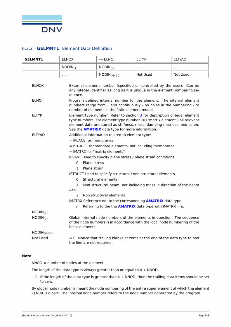
6.3.2 GELMNT1: Element Data Definition
GELMNT1 ELNOX → ELNO ELTYP ELTYAD
NODIN(1) NODIN(2) . . . . . .
. . . NODIN(NNOD) Not Used Not Used
ELNOX External element number (specified or controlled by the user). Can beany integer identifier as long as it is unique in the element numbering se-quence.
ELNO Program defined internal number for the element. The internal elementnumbers range from 1 and continuously - no holes in the numbering - tonumber of elements in the finite element model.
ELTYP Element type number. Refer to section 3 for description of legal elementtype numbers. For element type number 70 ("matrix element") all relevantelement data are stored as stiffness, mass, damping matrices, and so on.See the AMATRIX data type for more information.
ELTYAD Additional information related to element type:
= IPLANE for membranes
= ISTRUCT for standard elements, not including membranes
= IMATRX for "matrix elements"
IPLANE Used to specify plane stress / plane strain conditions
0 Plane stress
1 Plane strain
ISTRUCT Used to specify structural / non-structural elements
0 Structural elements
1 Non structural beam, not including mass in direction of the beamaxis
2 Non structural elements
IMATRX Reference no. to the corresponding AMATRIX data type.
n Referring to the the AMATRIX data type with IMATRX = n.
NODIN(1)
NODIN(2) Global internal node numbers of the elements in question. The sequenceof the node numbers is in accordance with the local node numbering of thebasic elements.
NODIN(NNOD)
Not Used = 0. Notice that trailing blanks or zeros at the end of the data type to padthe line are not required.
Note:
NNOD = number of nodes at the element.
The length of the data type is always greater than or equal to 4 + NNOD.
1. If the length of the data type is greater than 4 + NNOD, then the trailing data items should be setto zero.
By global node number is meant the node numbering of the entire super element of which the elementELNOX is a part. The internal node number refers to the node number generated by the program.
|Sesam Interface Format Description|SIF 10| Page 348

The program defined element number ranges from 1 up to number of elements.
The sequence of the data type will correspond to the program defined element numbering, ELNO.
Back to Section 6.3 Nodal Data and Element Geometry Definition
|Sesam Interface Format Description|SIF 10| Page 349

6.3.3 GELMNT2: Sub Element Description with Simple Correspondence between De-grees of Freedom of Sub Element and Relevant Assembly
GELMNT2 → SUBNO SLEVEL SELTYP ADDNO
T(1,1) T(2,1) T(3,1) T(1,2)
T(2,2) T(3,2) T(1,3) T(2,3)
T(3,3) T(1,4) T(2,4) T(3,4)
NNOD NOD(1) NOD(2) . . .
. . . NOD(NNOD)
SUBNO Sub element number within the relevant assembly which this super ele-ment is part of.
SLEVEL Super element level.
Should be identical to SLEVEL on the IDENT data type for this sub element.
The level of a super element is defined as the highest level number amongits sub elements plus 1. (Basic elements, i.e. beams, shells, springs, etc.have level zero.)
SELTYP Super element type number.
That is, the identification number of the sub element in question.
Should be identical to SELTYP on the IDENT data type for this sub element.
ADDNO Additional data type number, i.e. reference number referring to additionaldata specifications.
T(1,1)
T(2,1)
T(3,1)
T(1,2)
T(2,2)
T(3,2) Elements of the general transformation matrix T (see below).
T(1,3)
T(2,3)
T(3,3)
T(1,4)
T(2,4)
T(3,4)
NNOD Number of nodes of the sub element in question.
NOD(1)
NOD(2)
... Node numbers of the sub element in question.
|Sesam Interface Format Description|SIF 10| Page 350

NOD(NNOD)
Note: The sequence of the nodes defined on this data type, i.e. NOD(1), NOD(2), . . . , NOD(NNOD), must be inascending order of the internal node numbers of the super nodes on the level below. If this is not the casethe coupling between the super elements will be wrong.
The general transformation matrix T is defined through the following relation between the sub elementco-ordinate system x′ and the assembly, or basic super element assembly co-ordinate system x
x′ = Tx,
where
[x′
1
]=
[t(1,1) t(1,2)t(2,1) t(2,2)
] [x1
],
and where the sub-matrices are defined as follows
x′1x′2x′31
=
T(1,1) T(1,2) T(1,3) T(1,4)T(2,1) T(2,2) T(2,3) T(2,4)T(3,1) T(3,2) T(3,3) T(3,4)0 0 0 1
x1x2x31
. (6.2)
The 9 terms (cosines) of the first sub matrix t(1,1), i.e.
[t(1,1)
]=
T(1,1) T(1,2) T(1,3)T(2,1) T(2,2) T(2,3)T(3,1) T(3,2) T(3,3)
,are due to a possible rotation and/or mirroring of the sub element in question.
The three terms of the second sub matrix t(1,2), i.e.
[t(1,2)
]=
T(1,4)T(2,4)T(3,4)
,are the co-ordinates of the origin of the global (assembly) co-ordinate system in the sub element co-ordinatesystem.
Notice: as can be seen from equation 6.2 the explicit matrix zeros and unity element, i.e. T(4,1) = 0,T(4,2) = 0, T(4,3) = 0, and T(4,4) = 1 are not given on the GELMNT2 data type. This definition differs fromthe HSUPTRAN data type where they are explicitly given.
|Sesam Interface Format Description|SIF 10| Page 351

Back to Section 6.3 Nodal Data and Element Geometry Definition
|Sesam Interface Format Description|SIF 10| Page 352

6.3.4 GELREF1: Reference to Element Data
GELREF1 → ELNO MATNO ADDNO INTNO
MINTNO STRANO STRENO STREPONO
GEONO/OPT FIXNO/OPT ECCNO/OPT TRANSNO/OPT
GEONO(1) . . . GEONO(NNOD) FIXNO(1)
. . . FIXNO(NNOD) ECCNO(1) . . .
ECCNO(NNOD) TRANSNO(1) . . . TRANSNO(NNOD)
Shortest version for which GEONO, FIXNO, ECCNO, TRANSNO ≥ 0:
GELREF1 ELNO MATNO ADDNO INTNO
MINTNO STRANO STRENO STREPONO
GEONO FIXNO ECCNO TRANSNO
ELNO Program defined internal number for the element
MATNO Material number.
= 0 No material data attached to the element.
ADDNO Additional data type number, i.e. number referring to additional dataspecification.
= 0 No additional data attached to the element.
=-1 I.e when ADDNO = -1, then the item STRANO represents the elementtype number.
INTNO Integration station reference number for stiffness matrix, i.e. numberreferring to the specification of integration stations. An integrationstation is defined as:
- an assembly of integration points over a cross section of a1-dimensional (beam or bar) element,
- an assembly of integration points on a line through the thick-ness of a 2-dimensional element,
- one single integration point for a 3-dimensional element. Forfurther explanation see data type GELINT.
= 0 Default values of the analysis program are employed.
MINTNO Integration station reference number for mass and damping matrices.Integration station, see INTNO.
= 0 Default values of the analysis program are employed.
STRANO Initial strain number, i.e. a number referring to the specification of ini-tial strains. (To be given on data type ASTR which is not yet defined.)
As noted above under item ADDNO, if ADDNO = -1, then STRANO =element type.
|Sesam Interface Format Description|SIF 10| Page 353

STRENO Initial stress number, i.e. a number referring to the specification of ini-tial stresses. (To be given on data type ASTR which is not yet defined.)
STREPONO Stress point specification reference number. See data type GELSTRPfor further information.
GEONO/OPT Geometry reference number or option for geometry reference numberspecified later in this data type sequence.
>0 The geometry reference number (the same for all nodes in the ele-ment). GEONO(1), . . . , GEONO(NNOD) will not be specified.
=0 No geometry data is given, i.e. neither here nor on GEONO(1), . . . ,GEONO(NNOD).
=-1 Reference numbers to geometry data are specified later in this datatype sequence for all nodes, i.e. all GEONO(1), . . . , GEONO(NNOD) willbe given.
FIXNO/OPT Fixation reference number or option for fixation reference numbersspecified later in this data type sequence. The meaning assigned tothe values of FIXNO/OPT corresponds to those for GEONO/OPT.
ECCNO/OPT Eccentricity reference number or option for eccentricity referencenumbers specified later in this data type sequence. The mean-ing assigned to the values of ECCNO/OPT corresponds to those forGEONO/OPT.
TRANSNO/OPT Reference number for local co-ordinate system specification or op-tion for specification of local nodal co-ordinate systems later in thisdata type sequence. Refers to the GUNIVEC or BNTRCOS data types.The meaning assigned to the values of TRANSNO/OPT corresponds tothose for GEONO/OPT.
GEONO(1) Geometry reference number, i.e. number referring to thickness orcross sectional specification. Not employed for 3-dimensional ele-ments. GEONO(1) is the reference number for the 1st local node ofthe element, GEONO(i) will be the reference number for the i’th localnode.
GEONO(NNOD) Geometry reference number for the last local node of the element.
FIXNO(1) Number referring to the specification of degree of fixation (data typeBELFIX). FIXNO(1) is the reference number for the 1st local node of theelement, FIXNO(i) will be the reference number for the i’th local node.
FIXNO(NNOD) Degree of fixation reference number for the last local node of the ele-ment.
ECCNO(1) Eccentricity number for the first local node of the element, i.e. numberreferring to the specification of eccentricities.
ECCNO(NNOD) As ECCNO(1) only for the last local node.
TRANSNO(1) Number referring to the specification of the local element co-ordinatesystem for the 1st local node of the element. Refers to GUNIVEC orBNTRCOS data type depending on element type.
TRANSNO(NNOD) As TRANSNO(1) only for the last local node.
NNOD is the number of local nodes at the element.
|Sesam Interface Format Description|SIF 10| Page 354

NOTE: Parameters appear in succeeding order from third line.
The sequence of the data types will be in the program defined element numbering, ELNO.
Back to Section 6.3 Nodal Data and Element Geometry Definition
|Sesam Interface Format Description|SIF 10| Page 355

6.3.5 GNODE: Correspondence between External and Internal Node Numbering, andNumber of Degrees of Freedom at Each Node
GNODE NODEX → NODENO NDOF ODOF
NODEX External node number (specified or controlled by the user). Can be anyinteger identifier as long as it is unique in the node numbering sequence.
NODENO Program defined internal number for the node. The internal node numbersrange from 1 and continuously - no holes in the numbering - to number ofnodes in the finite element model.
NDOF Number of degrees of freedom at the node NODENO.
ODOF Order of the degrees of freedom at node NODENO. NDOF digits.
Example NDOF = 3, ODOF = 135 means 3 degrees of freedom. Two trans-lations x, z and and one rotation ry, respectively in the super element co-ordinate system, unless a local nodal co-ordinate system is specified (seethe BNDOF and BNTRCOS data types).
There will be one data type with the identifier GNODE for each node. The sequence of the data type willcorrespond to the internal node number, NODENO.
Back to Section 6.3 Nodal Data and Element Geometry Definition
|Sesam Interface Format Description|SIF 10| Page 356

6.4 Super Element Hierarchy Information in Highest Level T-File
Higher level data
HIERARCH Super Element Hierarchy Description see Section 6.4.1
HSUPSTAT Super Element Statistical Information see Section 6.4.2
HSUPTRAN Super Element Transformation see Section 6.4.3
|Sesam Interface Format Description|SIF 10| Page 357

6.4.1 HIERARCH: Super Element Hierarchy Description
HIERARCH NFIELD → IHREF ISELTY INDSEL
ISLEVL ITREF IHPREF NSUB
IHSREF(1) IHSREF(2) . . . IHSREF(NSUB)
This data type identifies a super element in the hierarchy. All the HIERARCH data types are written inthe highest level (top level) T-file.
The set of HIERARCH data types stored will define the super element hierarchy, see Figure 6.1. Note thatthe reference IHREF is unique for all "nodes" in the super element tree, i.e. unique for every HIERARCHdata type. If super elements are repeated, each repetition will have a unique hierarchy reference IHREF,although the super element type number is identical.
NFIELD Number of data fields on this data type (including this field and embeddednot used fields).
IHREF Hierarchy reference number. Number 1 is reserved for the top level superelement. In the Sesam system, the super element pre-processor Presel iswriting the HIERARCH data types and defining a unique number (IHREF)for each appearance of the different super elements. See also Figure 6.1below.
ISELTY Super element type number.
INDSEL Super element index number. Super element index in case of repeatedsuper elements. If super element is not repeated, INDSEL=1 must be used.
ISLEVL Super element level.
ITREF Reference to data type HSUPTRAN, defining super element transformationbetween actual super element and parent super element.
IHPREF Reference to HIERARCH data type of parent super element.
NSUB Number of sub elements in this super element.
IHSREF(i) Reference to HIERARCH data type for sub element number i.
|Sesam Interface Format Description|SIF 10| Page 358
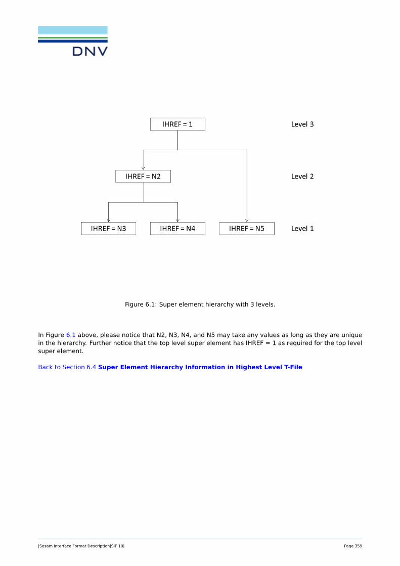
Figure 6.1: Super element hierarchy with 3 levels.
In Figure 6.1 above, please notice that N2, N3, N4, and N5 may take any values as long as they are uniquein the hierarchy. Further notice that the top level super element has IHREF = 1 as required for the top levelsuper element.
Back to Section 6.4 Super Element Hierarchy Information in Highest Level T-File
|Sesam Interface Format Description|SIF 10| Page 359

6.4.2 HSUPSTAT: Super Element Statistical Information
HSUPSTAT NFIELD → ISELTY NIDOF NRDOF
NBAND NELT LINDEP RELOADC
COMPLC
This data type lists statistical information about super elements. All the HSUPSTAT data types are writ-ten in the highest level (toplevel) T-file. The HSUPSTAT data type is referenced from the HIERARCH datatype through the super element type number (ISELTY).
NFIELD Number of data fields on this data type (including this field and embeddednot used fields).
ISELTY Super element type number.
NIDOF Estimated number of internal degrees of freedoms.
NRDOF Estimated number of retained degrees of freedoms.
NBAND Estimated bandwidth of the internal degrees freedoms. The estimatedbandwidth shall be equal to -1 if no bandwidth information exists.
NELT Estimated number of elements. The estimated number of elements is onlyrequired for first level super elements.
LINDEP If LINDEP > 0, this super element has linear dependent nodes.
RELOADC Number of real load cases.
COMPLC Number of complex load cases.
Back to Section 6.4 Super Element Hierarchy Information in Highest Level T-File
|Sesam Interface Format Description|SIF 10| Page 360

6.4.3 HSUPTRAN: Super Element Transformation
HSUPTRAN NFIELD → ITREF T(1,1) T(2,1)
T(3,1) T(4,1) T(1,2) T(2,2)
T(3,2) T(4,2) T(1,3) T(2,3)
T(3,3) T(4,3) T(1,4) T(2,4)
T(3,4) T(4,4)
This data type is defining the super element transformation between actual super element and parent superelement. All the HSUPTRAN data types are written in the highest level (the top level) T-file. The HSUP-TRAN data type is referenced from the HIERARCH data type through the super element transformationreference number, ITREF.
NFIELD Number of data fields on this data type (including this field and embeddednot used fields).
ITREF Reference to the HSUPTRAN data type (from the HIERARCH data type).
T(i,j) Term with indices i, j of the transformation matrix between actual superelement and parent super element, defined by:
X ′actual = T ˙ Xparent
The general transformation matrix T is defined through the following relation between the sub element co-ordinate system x′ and the assembly, or basic super element assembly co-ordinate system x
x′ = Tx,
where
[x′
1
]=
[t(1,1) t(1,2)t(2,1) t(2,2)
] [x1
],
and where the sub-matrices are defined as follows
x′1x′2x′31
=
T(1,1) T(1,2) T(1,3) T(1,4)T(2,1) T(2,2) T(2,3) T(2,4)T(3,1) T(3,2) T(3,3) T(3,4)0 0 0 1
x1x2x31
. (6.3)
The 9 terms (cosines) of the first sub matrix t(1,1), i.e.
|Sesam Interface Format Description|SIF 10| Page 361

[t(1,1)
]=
T(1,1) T(1,2) T(1,3)T(2,1) T(2,2) T(2,3)T(3,1) T(3,2) T(3,3)
,are due to a possible rotation and/or mirroring of the sub element in question.
The three terms of the second sub matrix t(1,2), i.e.
[t(1,2)
]=
T(1,4)T(2,4)T(3,4)
,are the co-ordinates of the origin of the global (assembly) co-ordinate system in the sub element co-ordinatesystem.
Notice: as can be seen from equation 6.3 the explicit matrix zeros and unity element, i.e. T(4,1) = 0,T(4,2) = 0, T(4,3) = 0, and T(4,4) = 1 are given on the HSUPTRAN data type. This definition differs from theGELMNT2 data type where they are not given.
Back to Section 6.4 Super Element Hierarchy Information in Highest Level T-File
|Sesam Interface Format Description|SIF 10| Page 362

6.5 Material Data
Higher level data
MAXDMP Axial Damper between Two Nodal Points see Section 6.5.1
MAXSPR Axial Spring between Two Nodal Points see Section 6.5.2
MGDAMP Damping Element to Ground see Section 6.5.3
MGSPRNG Spring Element to Ground see Section 6.5.4
|Sesam Interface Format Description|SIF 10| Page 363

6.5.1 MAXDMP: Axial Damper between Two Nodal Points
MAXDMP → MATNO DAMP
MATNO Material number referred to in the element specification, see theGELMNT1 and GELREF1 data types.
DAMP Axial damping constant.
The axial damping constant corresponds to the force to be applied in order to get a unit velocity in thedirection of the basic element.
Back to Section 6.5 Material Data
|Sesam Interface Format Description|SIF 10| Page 364

6.5.2 MAXSPR: Axial Spring between Two Nodal Points
MAXSPR → MATNO SCON
MATNO Material number referred to in the element specification, see theGELMNT1 and GELREF1 data types.
SCON Axial spring constant.
The axial spring constant corresponds to the force to be applied in order to get a unit displacement in thedirection of the basic element.
Back to Section 6.5 Material Data
|Sesam Interface Format Description|SIF 10| Page 365

6.5.3 MGDAMP: Damping Element to Ground
MGDAMP → MATNO NDOF C(1,1) C(2,1)
. . . . . . C(NDOF,1) C(2,2)
C(3,2) . . . . . . C(NDOF,2)
C(3,3) . . . . . . C(NDOF,NDOF)
MATNO Material number referred to in the element specification, see theGELMNT1 and GELREF1 data types.
NDOF Number of degrees of freedom at the node.
C(i,j) Elements of the damping matrix (only elements on and below the maindiagonal are stored, i.e. a symmetric damping matrix is assumed). Theelements are referred to a local co-ordinate system if defined (by TRANSNOon the GELREF1 data type), otherwise to the global co-ordinate system ofthe super element.
The damper to ground matrix is the viscous damping matrix.
Back to Section 6.5 Material Data
|Sesam Interface Format Description|SIF 10| Page 366

6.5.4 MGSPRNG: Spring Element to Ground
MGSPRNG → MATNO NDOF K(1,1) K(2,1)
. . . . . . K(NDOF,1) K(2,2)
K(3,2) . . . . . . K(NDOF,2)
K(3,3) . . . . . . K(NDOF,NDOF)
MATNO Material number referred to in the element specification, see theGELMNT1 and GELREF1 data types.
NDOF Number of degrees of freedom at the node.
K(i,j) Elements of the stiffness matrix (only elements on and below the maindiagonal are stored, i.e. a symmetric stiffness matrix is assumed). Theelements are referred to a local co-ordinate system if defined (by TRANSNOon the GELREF1 data type), otherwise to the global co-ordinate system ofthe super element.
The (i, j)’th element of the stiffness matrix corresponds to the force to be given in the i’th degree of freedomto get a unit displacement in the j’th degree of freedom.
Back to Section 6.5 Material Data
|Sesam Interface Format Description|SIF 10| Page 367
References
[1] Finite element results data types. Technical report 94-7099, DNV, 2021. 1
[2] O. Aamlid. Implementation of new membrane formulation for the low order flat shell elements in sestra.Technical Report 97-2056, Det Norske Veritas, 1997. 3.45, 3.46
[3] Aa. Berdal. Trsi – transition element between the twenty node isoparametric solid element and the eightnode subparametric curved thick shell element. Technical report VT87-3260, DNV, 1984. 3.31
[4] T.J.R. Hughes and T.E. Tezduyar. Finite elements based upon mindlin plate theory with particular ref-erence to the four-node bilinear isoparametric element. Journal of Applied Mechanics, September1981(3):587–596, 1981. 3.48.1, 3.49.1
[5] R. Karlsson. Contact element. theoretical manual. VSS Note TN091989, DNV, 1989. 3.41, 3.42, 3.43,3.44
[6] R. Karlsson. Contact element. users manual. VSS Note TN081989, DNV, 1989. 3.41, 3.42, 3.43, 3.44
[7] H.F. Klem et al. Finite element library (ellib) – users manual. Technical report VT87-3501, DNV, 1987.3.2, 3.3, 3.4, 3.5, 3.6, 3.10, 3.15, 3.16, 3.17, 3.18, 3.19, 3.20, 3.21, 3.23, 3.25, 3.26, 3.27, 3.28, 3.45,3.46

About DNVWe are the independent expert in risk management and quality assurance. Driven by our purpose, to safeguard life,
property and the environment, we empower our customers and their stakeholders with facts and reliable insights so
that critical decisions can be made with confidence. As a trusted voice for many of the world’s most successful
organizations, we use our knowledge to advance safety and performance, set industry benchmarks, and inspire and
invent solutions to tackle global transformations.
Digital SolutionsDNV is a world-leading provider of digital solutions and software applications with focus on the energy, maritime and
healthcare markets. Our solutions are used worldwide to manage risk and performance for wind turbines, electric
grids, pipelines, processing plants, offshore structures, ships, and more. Supported by our domain knowledge and
Veracity assurance platform, we enable companies to digitize and manage business critical activities in a sustainable,
cost-efficient, safe and secure way.
DNV | [email protected] | dnv.com/digital