ST.35 - Recommended standard format for data exchange of ...
Upload
khangminh22Category
view
0download
0
MERIS ESLDoc : QWG-MER-MERMAID-DF-02Name : MERMAID data formatIssue : 2 Rev: 3
MERMAID W.P. 2100 Date : 22/03/2012Page : i of 1
Title: MERMAID data format
Doc. no: QWG-MER-MERMAID-DF-02
Issue: 2
Revision: 3
Date: 22/03/2012
Name Company Function Signature Date
Prepared by: C. Mazeran ACRI-ST W.P. Manager 22/03/2012C. Lerebourg ACRI-ST Research Engineer 22/03/2012
Verified by: 22/03/2012Validated by: 22/03/2012
Copyright c© 2012 ACRI ST
MERIS ESLDoc : QWG-MER-MERMAID-DF-02Name : MERMAID data formatIssue : 2 Rev: 3
MERMAID W.P. 2100 Date : 22/03/2012Page : ii of 1
Change Record
Issue Revision Date Description Approval1 0 11/03/2009 Initial data format on March 20092 0 22/01/2010 Major update of the format with
respect to new extracted quanti-ties, including in-situ atmosphericparameters and correction of in-situ water marine reflectance forsolar illumination
2 1 30/08/2010 Update of MQC and PQC flagssection
2 2 28/02/2012 Typo correction in some units2 3 22/03/2012 upade of output header definition
(table 2)
Copyright c© 2012 ACRI ST

MERIS ESLDoc : QWG-MER-MERMAID-DF-02Name : MERMAID data formatIssue : 2 Rev: 3
MERMAID W.P. 2100 Date : 22/03/2012Page : iii of 1
Contents
1 General Information 1
2 Extracted files format 2
3 Statistical data file 8
4 Uncertainty file 9
5 MQC and PQC flags 105.1 MQC: Measurement Quality Control . . . . . . . . . . . . . . . . . . . . . . . . 105.2 PQC: Processing Quality Control . . . . . . . . . . . . . . . . . . . . . . . . . . 11
6 Correction of in-situ reflectance for solar irradiance 126.1 Calculation of MERIS solar irradiance . . . . . . . . . . . . . . . . . . . . . . . . 126.2 Correction . . . . . . . . . . . . . . . . . . . . . . . . . . . . . . . . . . . . . . 12
Copyright c© 2012 ACRI ST

MERIS ESLDoc : QWG-MER-MERMAID-DF-02Name : MERMAID data formatIssue : 2 Rev: 3
MERMAID W.P. 2100 Date : 22/03/2012Page : 1 of 12
1 General Information
The MERMAID project aims at making available an easy-to-use centralised database of mergedin-situ optical measurements with concurrent MERIS acquisitions to Ocean Colour researchers in-volved in the MERIS mission. Details on the project and access to the database are available onhttp://hermes.acri.fr/mermaid.
This document describes the data format of the extraction generated by the web interface.
The output of the extraction process generates four semi-colon separated files and a text file:
1. extraction.csv contains data of the whole block of pixels for each matchup (either 1, 3x3or 5x5 pixels).
2. extractionAvg.csv contains averaged data of the block of pixels, computed upon the flagacceptance and statistical screening options.
3. stats.csv contains statistics comparing MERIS water-leaving reflectance ρw(λ) to in-situmeasurements. Statistics are computed per individual sites occuring in the extraction as wellas for the whole dataset.
4. uncertainties.csv contains the in-situ water reflectance uncertainties provided by the PI,when available.
5. parameter.txt is a record of the extraction criteria.
Depending on the user’s choice, extraction may also include RGB of Level 1 scenes (in direc-tory RGB) and plots to compare MERIS water reflectance retrieval to in-situ data (scatter plots,histograms in directory plots).
The MERIS quantities are either Level 1b, Level 2, auxiliary data or intermediary data. Thefirst three kinds of data are detailed in the MERIS product handbook available athttp://envisat.esa.int/pub/ESA DOC/ENVISAT/MERIS/meris.ProductHandbook.2 1.pdf.
The intermediary data are detailed in the MERIS Detailed Processing Model (DPM) availableat http://earth.esa.int/pub/ESA DOC/ENVISAT/MERIS/MERIS-DPM-L2-i8r0B.pdf.
Additional informations about the models used in MERIS and MERMAID can be found in theReference Model Document (RMD) available athttp://envisat.esa.int/instruments/meris/rfm/rmd third reprocessing ocean.pdf.
Further details on the oceanic in-situ data are given on the web site through the MERIS Op-tical Measurement Protocols document (http://hermes.acri.fr/mermaid/dataproto/CO-SCI-ARG-TN-0008 MERIS Optical Measurement Protocols Issue2 Aug2011.pdf), or can be requested fromthe corresponding PI, whose affiliation and contact email are displayed on the MERMAID DataPolicy page (http://hermes.acri.fr/mermaid/policy/policy.php).
The atmospheric in-situ data come from the AERONET web sitehttp://aeronet.gsfc.nasa.gov/new web/ocean color.html.
Copyright c© 2012 ACRI ST

MERIS ESLDoc : QWG-MER-MERMAID-DF-02Name : MERMAID data formatIssue : 2 Rev: 3
MERMAID W.P. 2100 Date : 22/03/2012Page : 2 of 12
2 Extracted files format
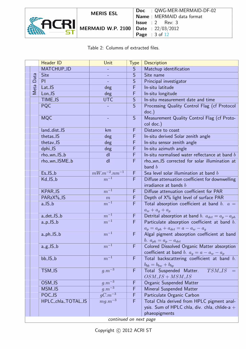
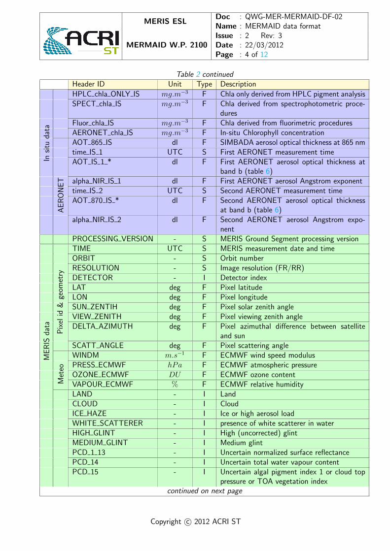
The data format of extracted files extraction.csv and extractionAvg.csv is detailed in table 2.Units and type definitions are given in table 3 and 4. The time format UTC iso 860 is defined
as yyyymmddThhmmssZ where yyyymmdd is year, month, day and hhmmss is UTC time expressedas hour, minute, second.
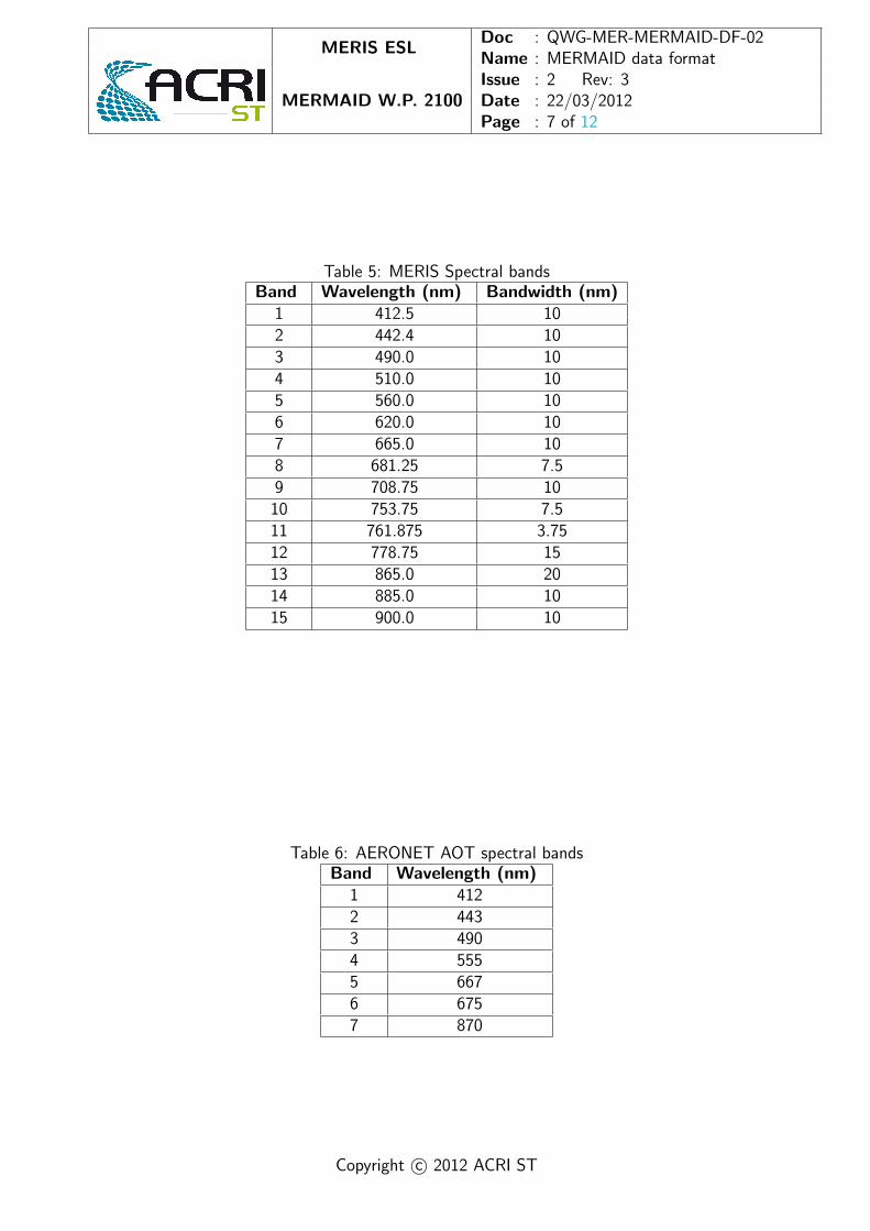
Spectral quantities are extracted for three different band sets (see table 5 for MERIS banddefinition):
• The Level 1 TOA radiance and reflectances are extracted on all 15 bands;
• the NIR residual marine signal computed by BPAC is extracted at only B9, B12, B13 andB14;
• all other Level 2 signals are extracted on 13 bands: B1 to B10, B12, B13, B14.
For AERONET atmospheric data, two measurements bracketing the satellite overpath are avail-able: the closest atmospheric dataset before and after satellite overpath (with suffix ” 1” and ” 2”respectively).
Note that some of the variables, although defined as integers, are printed out as floating pointnumbers with no decimal numbers in order to support the ”NaN” value. For example, the aerosolmodel indexes (parameters iaer1 and iaer2) are integers and printed as floating points (”f3.0”).They therefore appear in the csv files with decimal points.
In file extractionAvg.csv, note that quantities iaer1, iaer2 and aer mix are set to ”NaN”because their mean would be meaningless. On the contrary, the mean of the detector index iscomputed for reference, yet it might be a floating point value because of duplicated detectors inthe macro-pixel.
Copyright c© 2012 ACRI ST
MERIS ESLDoc : QWG-MER-MERMAID-DF-02Name : MERMAID data formatIssue : 2 Rev: 3
MERMAID W.P. 2100 Date : 22/03/2012Page : 3 of 12
Table 2: Columns of extracted files.
Header ID Unit Type DescriptionMATCHUP ID - S Matchup identificationSite - S Site namePI - S Principal investigatorLat IS deg F In-situ latitude
Met
aD
ata
Lon IS deg F In-situ longitudeTIME IS UTC S In-situ measurement date and timePQC - S Processing Quality Control Flag (cf Protocol
doc.)MQC - S Measurement Quality Control Flag (cf Proto-
col doc.)land dist IS km F Distance to coastthetas IS deg F In-situ derived Solar zenith anglethetav IS deg F In-situ sensor zenith angledphi IS deg F In-situ azimuth anglerho wn IS b dl F In-situ normalised water reflectance at band brho wn ISME b dl F rho wn IS corrected for solar illumination at
band bEs IS b mW.m−2.nm−1 F Sea level solar illumination at band bKd IS b m−1 F Diffuse attenuation coefficient for downwelling
irradiance at bands bKPAR IS m−1 F Diffuse attenuation coefficient for PARPARzX% IS m F Depth of X% light level of surface PARa IS b m−1 F Total absorption coefficient at band b. a =
aw + ag + apa det IS b m−1 F Detrital absorption at band b. adet = ap−apha p IS b m−1 F Particulate absorption coefficient at band b.
ap = aph + adet = a− aw − aga ph IS b m−1 F Algal pigment absorption coefficient at band
b. aph = ap − adeta g IS b m−1 F Colored Dissolved Organic Matter absorption
coefficient at band b. ag = a− aw − apbb IS b m−1 F Total backscattering coefficient at band b.
bbb = bbw + bbpTSM IS g.m−3 F Total Suspended Matter. TSM IS =
OSM IS +MSM ISOSM IS g.m−3 F Organic Suspended MatterMSM IS g.m−3 F Mineral Suspended MatterPOC IS gC.m−3 F Particulate Organic CarbonHPLC chla TOTAL IS mg.m−3 F Total Chla derived from HPLC pigment anal-
ysis. Sum of HPLC chla, div. chla, chlide-a +phaeopigments
continued on next page
Copyright c© 2012 ACRI ST
MERIS ESLDoc : QWG-MER-MERMAID-DF-02Name : MERMAID data formatIssue : 2 Rev: 3
MERMAID W.P. 2100 Date : 22/03/2012Page : 4 of 12
Table 2 continuedHeader ID Unit Type Description
HPLC chla ONLY IS mg.m−3 F Chla only derived from HPLC pigment analysisSPECT chla IS mg.m−3 F Chla derived from spectrophotometric proce-
duresFluor chla IS mg.m−3 F Chla derived from fluorimetric procedures
Oce
anic
AERONET chla IS mg.m−3 F In-situ Chlorophyll concentrationAOT 865 IS dl F SIMBADA aerosol optical thickness at 865 nmtime IS 1 UTC S First AERONET measurement timeAOT IS 1 * dl F First AERONET aerosol optical thickness at
band b (table 6)alpha NIR IS 1 dl F First AERONET aerosol Angstrom exponenttime IS 2 UTC S Second AERONET measurement timeAOT 870 IS * dl F Second AERONET aerosol optical thickness
at band b (table 6)
Insi
tuda
ta
AE
RO
NE
T
alpha NIR IS 2 dl F Second AERONET aerosol Angstrom expo-nent
PROCESSING VERSION - S MERIS Ground Segment processing versionTIME UTC S MERIS measurement date and timeORBIT - S Orbit numberRESOLUTION - S Image resolution (FR/RR)DETECTOR - I Detector indexLAT deg F Pixel latitudeLON deg F Pixel longitudeSUN ZENTIH deg F Pixel solar zenith angleVIEW ZENITH deg F Pixel viewing zenith angleDELTA AZIMUTH deg F Pixel azimuthal difference between satellite
and sun
Pix
elid
&ge
omet
ry
SCATT ANGLE deg F Pixel scattering angleWINDM m.s−1 F ECMWF wind speed modulusPRESS ECMWF hPa F ECMWF atmospheric pressureOZONE ECMWF DU F ECMWF ozone content
ME
RIS
data
Met
eo
VAPOUR ECMWF % F ECMWF relative humidityLAND - I LandCLOUD - I CloudICE HAZE - I Ice or high aerosol loadWHITE SCATTERER - I presence of white scatterer in waterHIGH GLINT - I High (uncorrected) glintMEDIUM GLINT - I Medium glintPCD 1 13 - I Uncertain normalized surface reflectancePCD 14 - I Uncertain total water vapour contentPCD 15 - I Uncertain algal pigment index 1 or cloud top
pressure or TOA vegetation indexcontinued on next page
Copyright c© 2012 ACRI ST
MERIS ESLDoc : QWG-MER-MERMAID-DF-02Name : MERMAID data formatIssue : 2 Rev: 3
MERMAID W.P. 2100 Date : 22/03/2012Page : 5 of 12
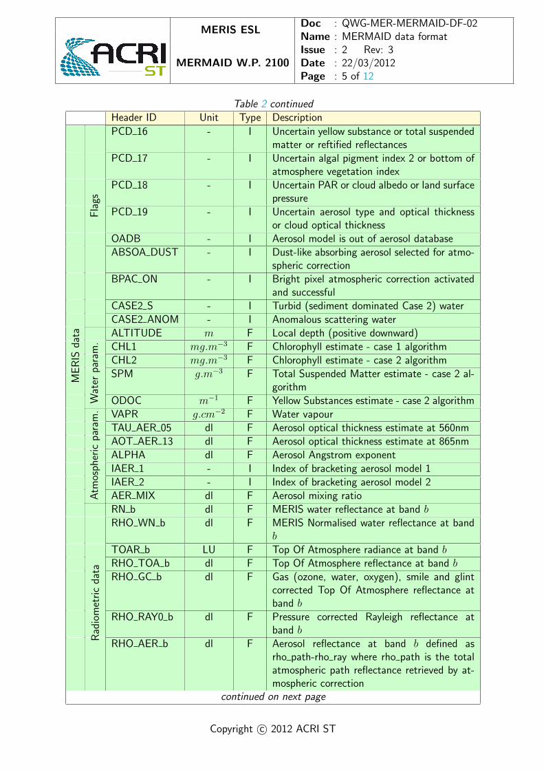
Table 2 continuedHeader ID Unit Type Description
PCD 16 - I Uncertain yellow substance or total suspendedmatter or reftified reflectances
PCD 17 - I Uncertain algal pigment index 2 or bottom ofatmosphere vegetation index
PCD 18 - I Uncertain PAR or cloud albedo or land surfacepressure
PCD 19 - I Uncertain aerosol type and optical thicknessor cloud optical thickness
OADB - I Aerosol model is out of aerosol databaseABSOA DUST - I Dust-like absorbing aerosol selected for atmo-
spheric correctionBPAC ON - I Bright pixel atmospheric correction activated
and successfulCASE2 S - I Turbid (sediment dominated Case 2) water
Fla
gs
CASE2 ANOM - I Anomalous scattering waterALTITUDE m F Local depth (positive downward)CHL1 mg.m−3 F Chlorophyll estimate - case 1 algorithmCHL2 mg.m−3 F Chlorophyll estimate - case 2 algorithmSPM g.m−3 F Total Suspended Matter estimate - case 2 al-
gorithm
Wat
erpa
ram
.
ODOC m−1 F Yellow Substances estimate - case 2 algorithmVAPR g.cm−2 F Water vapourTAU AER 05 dl F Aerosol optical thickness estimate at 560nmAOT AER 13 dl F Aerosol optical thickness estimate at 865nmALPHA dl F Aerosol Angstrom exponentIAER 1 - I Index of bracketing aerosol model 1IAER 2 - I Index of bracketing aerosol model 2
ME
RIS
data
Atm
osph
eric
para
m.
AER MIX dl F Aerosol mixing ratioRN b dl F MERIS water reflectance at band bRHO WN b dl F MERIS Normalised water reflectance at band
bTOAR b LU F Top Of Atmosphere radiance at band bRHO TOA b dl F Top Of Atmosphere reflectance at band bRHO GC b dl F Gas (ozone, water, oxygen), smile and glint
corrected Top Of Atmosphere reflectance atband b
RHO RAY0 b dl F Pressure corrected Rayleigh reflectance atband b
Rad
iom
etri
cda
ta
RHO AER b dl F Aerosol reflectance at band b defined asrho path-rho ray where rho path is the totalatmospheric path reflectance retrieved by at-mospheric correction
continued on next page
Copyright c© 2012 ACRI ST
MERIS ESLDoc : QWG-MER-MERMAID-DF-02Name : MERMAID data formatIssue : 2 Rev: 3
MERMAID W.P. 2100 Date : 22/03/2012Page : 6 of 12
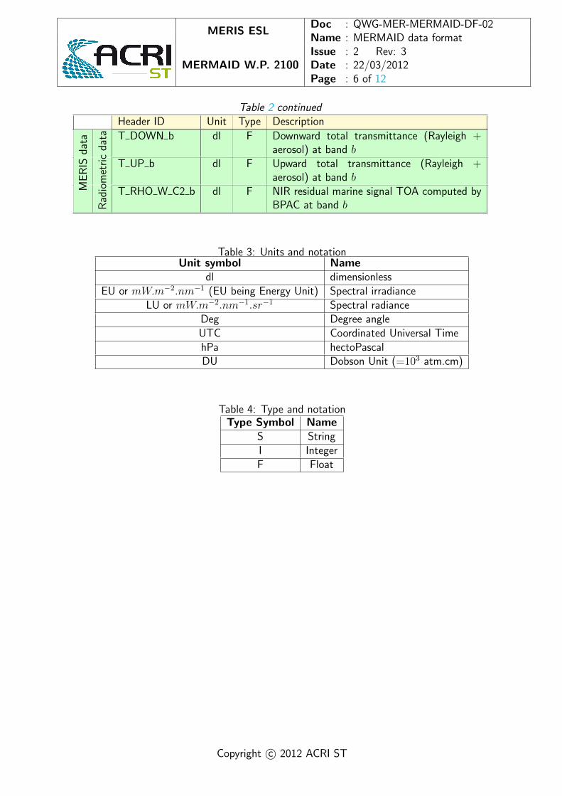
Table 2 continuedHeader ID Unit Type Description
T DOWN b dl F Downward total transmittance (Rayleigh +aerosol) at band b
T UP b dl F Upward total transmittance (Rayleigh +aerosol) at band b
ME
RIS
data
Rad
iom
etri
cda
ta
T RHO W C2 b dl F NIR residual marine signal TOA computed byBPAC at band b
Table 3: Units and notationUnit symbol Name
dl dimensionlessEU or mW.m−2.nm−1 (EU being Energy Unit) Spectral irradiance
LU or mW.m−2.nm−1.sr−1 Spectral radianceDeg Degree angleUTC Coordinated Universal TimehPa hectoPascalDU Dobson Unit (=103 atm.cm)
Table 4: Type and notationType Symbol Name
S StringI IntegerF Float
Copyright c© 2012 ACRI ST
MERIS ESLDoc : QWG-MER-MERMAID-DF-02Name : MERMAID data formatIssue : 2 Rev: 3
MERMAID W.P. 2100 Date : 22/03/2012Page : 7 of 12
Table 5: MERIS Spectral bandsBand Wavelength (nm) Bandwidth (nm)
1 412.5 102 442.4 103 490.0 104 510.0 105 560.0 106 620.0 107 665.0 108 681.25 7.59 708.75 10
10 753.75 7.511 761.875 3.7512 778.75 1513 865.0 2014 885.0 1015 900.0 10
Table 6: AERONET AOT spectral bandsBand Wavelength (nm)
1 4122 4433 4904 5555 6676 6757 870
Copyright c© 2012 ACRI ST

MERIS ESLDoc : QWG-MER-MERMAID-DF-02Name : MERMAID data formatIssue : 2 Rev: 3
MERMAID W.P. 2100 Date : 22/03/2012Page : 8 of 12
3 Statistical data file
The data contained in stats.csv are statistical parameters derived from extractionAvg.csv. Theestimators are summarised in table 7 below, where xi stands for the reference in-situ normalizedwater-leaving reflectance and yi for the MERIS’one. The overline stands for the mean over the Navailable points.
Note that two references are possible: directly the in-situ reflectance provided by the PI (andnormalised) rho wn IS, or its correction for MERIS solar illumination rho wn ISME, see section6. The choice is given to the user in the interface. No matchup will be returned if the latter ischosen and PI did not provide in-situ solar irradiance.
Table 7: Format of file stats.csvHeader Variable Formulalambda Wavelength (nm)N Number of points
RPD Average Relative (signed) percent difference RPD =1
N
N∑i=1
yi − xixi
|RPD| Average Relative (unsigned) percent difference RPD =1
N
N∑i=1
|yi − xi|xi
MAD Mean Arithmetic Difference MAD ==1
N
N∑i=1
yi − xi
RMSE Root Mean Squared Error RMSE =
√√√√ 1
N
N∑i=1
(yi − xi)2
slope Linear fit slope slope =xiyi − xiyix2i − (xi)
2
intercept Linear fit offset intercept = yi − slope ∗ xi
r2 Coefficient of determination(xiyi − xiyi)
2(x2i − (xi)
2)2 (
y2i − (yi)2)2
Copyright c© 2012 ACRI ST

MERIS ESLDoc : QWG-MER-MERMAID-DF-02Name : MERMAID data formatIssue : 2 Rev: 3
MERMAID W.P. 2100 Date : 22/03/2012Page : 9 of 12
4 Uncertainty file
The uncertainties.csv file contains, when available, the in-situ water reflectance percentage un-certainties provided by the PI’s.
Copyright c© 2012 ACRI ST
MERIS ESLDoc : QWG-MER-MERMAID-DF-02Name : MERMAID data formatIssue : 2 Rev: 3
MERMAID W.P. 2100 Date : 22/03/2012Page : 10 of 12
5 MQC and PQC flags
Flags are required to describe the level of quality control (QC) applied to the in-situ data. Twoflags are defined in MERMAID: PQC and MQC, also defined in the MERIS Optical MeasurementProtocols.
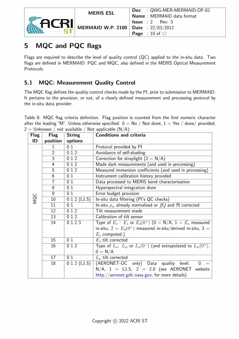
5.1 MQC: Measurement Quality Control
The MQC flag defines the quality control checks made by the PI, prior to submission to MERMAID.It pertains to the provision, or not, of a clearly defined measurement and processing protocol bythe in-situ data provider.
Table 8: MQC flag criteria definition. Flag position is counted from the first numeric characterafter the leading ”M”. Unless otherwise specified: 0 = No / Not done, 1 = Yes / done/ provided,2 = Unknown / not available / Not applicable (N/A).
Flag Flag String Conditions and criteriaID position options
MQ
C
1 0 1 Protocol provided by PI2 0 1 2 Avoidance of self-shading3 0 1 2 Correction for straylight (2 = N/A)4 0 1 2 Made dark measurements (and used in processing)5 0 1 2 Measured immersion coefficients (and used in processing)6 0 1 Instrument calibration history provided7 0 1 Data processed to MERIS band characterisation8 0 1 Hyperspectral integration done9 0 1 Error budget provision
10 0 1 2 (L1.5) In-situ data filtering (PI’s QC checks)11 0 1 In-situ ρw already normalised or f/Q and R corrected12 0 1 2 Tilt measurement made13 0 1 2 Calibration of tilt sensor14 0 1 2 3 Type of Es : Es or Ed(0
+) (0 = N/A, 1 = Es measuredin-situ, 2 = Ed(0
+) measured in-situ/derived in-situ, 3 =Es computed.)
15 0 1 Es tilt corrected16 0 1 2 Type of Lu: Lw or Lu(0
−) (and extrapolated to Lw(0+).
0 = N/A17 0 1 Lu tilt corrected18 0 1 2 (L1.5) (AERONET-OC only) Data quality level: 0 =
N/A, 1 = L1.5, 2 = 2.0 (see AERONET websitehttp://aeronet.gsfc.nasa.gov, for more details)
Copyright c© 2012 ACRI ST

MERIS ESLDoc : QWG-MER-MERMAID-DF-02Name : MERMAID data formatIssue : 2 Rev: 3
MERMAID W.P. 2100 Date : 22/03/2012Page : 11 of 12
5.2 PQC: Processing Quality Control
The PQC flag defines the post-submission quality control performed on the in-situ data, and includesinformation on the normalisation procedure. The flag provides information on the MERMAID in-situ processing for both the optical data received (e.g. ρw) and the atmospheric parameters (e.g.α) newly added to the database.
Table 9: PQC flag criteria definition. Flag position is counted from the first numeric characterafter the leading ”P”. Unless otherwise specified: 0 = No / Not done, 1 = Yes / done/ provided,2 = Unknown / not available.
Flag Flag String Conditions and criteriaID position options
PQ
C
1 0 1 Passed in-situ ρw QC2 0 1 2 Hyperspectral integration3 0 1 Case 1 Normalisation by MERMAID ∗
4 0 1 Case 2 Normalisation5 0 1 Band shifted correction (AERONET-OC data only;
presently only AAOT)6 0 1 Nearest neighbour (refer to MERIS Optical Measurement
Protocols): 0 = data at bands greater than ± 5nm fromMERIS 1 = data at bands less than ± 5nm from MERIS**NOMAD only: Flag is 0 when data is at 560 nm and1 when at 555 nm
7 0 1 AlphaNIR (1 & 2) derived from 870-675 nm8 0 1 AlphaNIR (1 & 2) derived from 870-667 nm
∗ See MQC flag #11 to check if normalisation has already been performed by PI.
Copyright c© 2012 ACRI ST

MERIS ESLDoc : QWG-MER-MERMAID-DF-02Name : MERMAID data formatIssue : 2 Rev: 3
MERMAID W.P. 2100 Date : 22/03/2012Page : 12 of 12
6 Correction of in-situ reflectance for solar irradiance
Because the solar illumination used in the computation of the in-situ reflectance might be differentfrom that of the MERIS processing, MERMAID contains a complementary in-situ water reflectancerho wn ISME, consistent with the MERIS formulation of Es. This quantity is for instance usedin the vicarious calibration of MERIS. The in-situ solar illumination provided by PI may comefrom measurement or models, depending on the sites. It is not directly stored in the MERMAIDextraction. Details on this quantity can be found in the MERIS Optical Measurement Protocol.
6.1 Calculation of MERIS solar irradiance
For a given detector indexed by i, we have from DPM Level 2 step 2.1.4 and RMD
ρTOA(λ) =πTOAR(λ)seasonal fact
cos θMERISs F0(λ, i)
=πTOAR(λ)
cos θsF0(λ, i)d2
where ρTOA is the Top of Atmosphere reflectance, TOAR is the TOA radiance, θMERISs is the sun
zenith angle at measurement time, F0(i) is the extra-terrestrial sun irradiance at reference date forMERIS detector i and seasonal fact = 1/d2 the correction factor for seasonal variation of sunirradiance.
It follows that the MERIS Solar irradiance can be directly deduced from the MERMAID extrac-tion by
F0d2(λ, i) =
πTOAR(λ)
cos θMERISs ρTOA(λ, i)
.
6.2 Correction
Given the previous F0d2, a MERIS-like total downward irradiance at sea-level for any solar zenith
angle θ writesEMERIS
s (λ, θ) = TMERISd (λ, θ) cos(θ)F0d
2,
where TMERISd (λ, θ) is the total downward transmittance as computed in the MERIS processing,
which includes the Rayleigh, aerosol and ozone contribution. In particular, this transmittance mayrequire auxiliary data like aerosol models and meteorological quantity of the current pixel. It is thusdependent on the MEGS version.
Then, starting from the in-situ total downward irradiance EISS provided by the PI, the correction
simply writes
rho wn ISME(λ) = rho wn IS(λ)EIS
s (λ)
EMERISs (λ, θISs )
.
Copyright c© 2012 ACRI ST
Copyright © 2022 FDOKUMEN