SMP Negeri 4 Ngaglik - Paper Format for the Proceeding of ...
Upload
khangminh22Category
view
1download
0
International Journal of Hybrid Information Technology
Vol.6, No.5 (2013), pp.141-150
http://dx.doi.org/10.14257/ijhit.2013.6.5.13
ISSN: 1738-9968 IJHIT
Copyright ⓒ 2013 SERSC
Design and Implementation of Two-wire Electronic Tag Picking
System
Feng Tian1, Tengfei Fu
2 and Jing Fu
3
1College of Automation, Shenyang Aerospace University, Shenyang, China
2College of Computer Science, Shenyang Aerospace University, Shenyang, China
3Shenyang Polytechnic College, Shenyang, China
Abstract
The paper introduces a new electronic tag device and describes system structure, design of
software and hardware, critical circuit and communication protocols in details .Two-wire bus
transmission is designed to replace the conventional RS485 four-wire transmission, which
saves 50% of the conductive wire material. The experiment proves the feasibility of the system
and the load capacity of the two-wire bus.
Keywords: electronic tag; two-wire; pick operation
1. Introduction
Picking operation is the most onerous and error-prone work in logistics distribution center.
The traditional way of picking is that warehouse pickers find the appropriate shelf according
to the invoices, which need pickers to be very clear of the position of the goods. Obviously, it
seems not easy to take care of a large-scale storage. That leads to excess workload, low
efficiency, and error-prone, and at the same time, leading to management inconvenience and
management inefficiency. Electronic tag picking system is a way to improve the quality of
traditional logistics operations and the efficiency of traditional logistics effectively.
Foreign research of electronic tags picking system has an early start, especially L-PICK
auxiliary picking system designed by the company of AIOI. The system’s core technology is
based on TW (two-wire) system, involving patented packaging chips and patented score
technology. Domestic research in the field of assisted picking system started late, mainly
clustered in coastal economic belt where economic is more developed, and most technologies
are introduced. For example, Shanghai ZEJU Logistics Equipment Co., Ltd. electronic tags
using RS485 four-wire communication bus production. Relative to the two-wire electronic
tags, it is not easy for wiring and error-prone on the shelves. Duan Cun-hui[2]
et al proposed
layered system whose signal was transported by RS485 bus. Wang Yu-quan[3]
et al introduced
the TCP/IP to RS-232 technology, selected the RS-485 as the communication bus. So there is
a gap with foreign TW two-wire picking auxiliary systems in technology.
The system of the paper uses a DC power line carrier technology to achieve the two -
wire bus transfer, making wiring easier, less error-prone and saving in the cost of wire
material on the shelves. In addition, it narrows the gaps with foreign electronic tags
auxiliary picking system in technology. Enhancement of fault detection function based
on actual needs makes the system more perfect.
International Journal of Hybrid Information Technology
Vol.6, No.5 (2013)
142 Copyright ⓒ 2013 SERSC
2. System Composition and Operating Principle
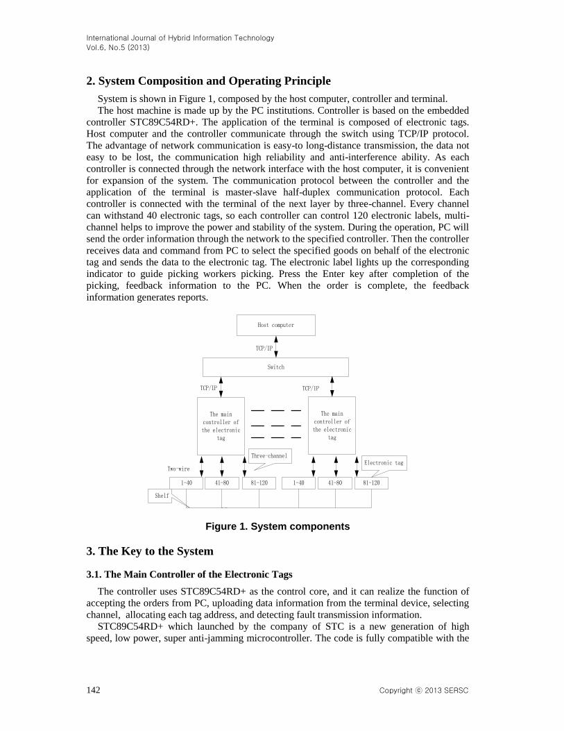
System is shown in Figure 1, composed by the host computer, controller and terminal.
The host machine is made up by the PC institutions. Controller is based on the embedded
controller STC89C54RD+. The application of the terminal is composed of electronic tags.
Host computer and the controller communicate through the switch using TCP/IP protocol.
The advantage of network communication is easy-to long-distance transmission, the data not
easy to be lost, the communication high reliability and anti-interference ability. As each
controller is connected through the network interface with the host computer, it is convenient
for expansion of the system. The communication protocol between the controller and the
application of the terminal is master-slave half-duplex communication protocol. Each
controller is connected with the terminal of the next layer by three-channel. Every channel
can withstand 40 electronic tags, so each controller can control 120 electronic labels, multi-
channel helps to improve the power and stability of the system. During the operation, PC will
send the order information through the network to the specified controller. Then the controller
receives data and command from PC to select the specified goods on behalf of the electronic
tag and sends the data to the electronic tag. The electronic label lights up the corresponding
indicator to guide picking workers picking. Press the Enter key after completion of the
picking, feedback information to the PC. When the order is complete, the feedback
information generates reports.
Host computer
Switch
TCP/IP
The main controller of the electronic
tag
TCP/IP TCP/IP
1-40 41-80 81-120
Two-wire
1-40 41-80 81-120
Shelf
Electronic tagThree-channel
The main controller of the electronic
tag
Figure 1. System components
3. The Key to the System
3.1. The Main Controller of the Electronic Tags
The controller uses STC89C54RD+ as the control core, and it can realize the function of
accepting the orders from PC, uploading data information from the terminal device, selecting
channel, allocating each tag address, and detecting fault transmission information.
STC89C54RD+ which launched by the company of STC is a new generation of high
speed, low power, super anti-jamming microcontroller. The code is fully compatible with the

International Journal of Hybrid Information Technology
Vol.6, No.5 (2013)
Copyright ⓒ 2013 SERSC 143
traditional 8051 SCM, the operating frequency range form 0 to 40MHz, equivalent to an
ordinary 8051 0-80MHz. In addition to the integrated 256 bytes of internal RAM, the chip
also integrates the 1024 bytes of extended RAM address range 0000H-03FFH.
Figure 2 is a system block diagram of the controller, wherein the microcontroller module
uses its I/O ports to simulate the SPI interface. Through the SPI interface, the microcontroller
is connected to the network chip of W5200 to complete the communication between the
controller and the PC. TCP/IP protocol is used between the controller and the PC for the
communication protocol, and the PC is regarded as the server and each controller is regarded
as a client. For the data of EEPROM after power failure will not be lost, it is used to store
each controller’s hardware address, IP address, port number, destination IP address and
destination port number. Since the controller needs to achieve store-and-forward function
(store the data information sent from the PC and electronic tags), it should have enough
memory space. The system uses the 6264 to expend eight thousand bytes of memory space.
8255 is used for expending I/O in order to have sufficient I/O pins to exchange data
information with peripherals. Then GM8123 chip controls serial port expansion mode with
the expansion of the I/O pins. A full-duplex serial port is expanded into three standard serial
ports by the chip of GM8123. Thus the controller will have three channels which are
connected with the application terminal of the next layer.
W5200 network chip
MCU module
8255 I/O port
expansion module
External expansion RAM
GM8123 serial port
expansion module
Two-wire modulation and
demodulation circuit
Power
EEPROM module
Two-wire modulation and
demodulation circuit
Two-wire modulation and
demodulation circuit
Figure 2. Controller system block diagram
3.2. Two-wire bus design
The so-called TW two-wire system is that the electric power and signals are transported by
the same two wires. The advantage of the two-wire communication to the RS485 four-wire
communication is:
(1)Compared with the four-wire bus, two-wire bus saves conductor material for half of the
original.
(2)Comparing to the four-wire bus, two-wire bus wiring is not easy to go wrong. In
addition, shelves wiring becomes simple and the cost of construction is low. The two-wire
system is less susceptible to interference and suitable for long distance transmission.
Load power depends on the power provided by the two-wire modulation and demodulation
circuit. Due to a controller with three channels has three modulation and demodulation circuit,
the stability of the system and the load capacity have been improved. As shown in Figure 3
for the two-wire modulation and demodulation circuit, as the power of the bus is very large
and the on-off frequency of modulation circuit is relatively high, we choose N channel
enhancement mode MOS tube as the modulation switch. The noise coefficient of MOS pipe is

International Journal of Hybrid Information Technology
Vol.6, No.5 (2013)
144 Copyright ⓒ 2013 SERSC
small and the power consumption of it is low. In addition, MOS pipe has the advantage of
wide range of working voltage. DE as the communication flag signal works normally in low
level state, and when you want to communicate DE is set to high level. Communication starts
after one millisecond delay. After the completion of the communication, DE is set to low
again. Due to the signals on the bus which is modulated by the MOS tube are opposite to the
ones sent by the TXD, the inverter 74LS04 is added after the TXD to make the bus signals
follow the host’s change.
Communication resistor
74LS04LM339
104
1K
1K
+24V
-24V
TXD
RXD
+5V
Two-wire bus
+
-
DE
10K
1K 1K
Optocouplers
Figure 3 .Modulation and demodulation circuit of controller’s two-wire bus
3.3. Terminal equipment electronic tags
As pickers’ interface, the electronic tag terminal uses AT89C2051 MCU as the control
core. It configures high brightness LED display, receiving the command and the data
information transferred from the controller by the two-wire modulation and demodulation
circuit. After the electronic tag deals with the command and data information which is sent
from the controller, it will light up the LED indicator according to the result of the processing.
Thus the pickers go to pick goods prompted by the indicator and press the corresponding
button to turn the LED indicator down when he finishes picking. At the same time, the
electronic tag unit will send the information which the led goes out to the controller timely,
and then the information will be transferred to the host by the controller.
The signal which is separated by the two-wire modulation and demodulation circuit in the
two-wire bus is transferred to the microcontroller AT89C2051, and then the microcontroller
AT89C2051 depends on the received information to determine whether its own address is
called. If it does not call itself, it will not act, and the multi-machine communication control
bit which called SM2 is 1. At this time, only when ninth bit which is called RB8 of the
received information is 1, the AT89C2051 can be promised to receive information.
On the other hand, if it calls itself, the AT89C2051 will set control bit SM2 of the multi-
machine communication into 0. Thus AT89C2051 can receive information at any time and
send its correct address to the controller. Then in case the controller receives the correct
address of the electronic tag, it will set the ninth bit called TB8 of its sending message as 0.
At this time, due to the other electronic tags’ multi-machine communication control bit which
called SM2 is 1, their control chips AT89C2051 are not promised to receive message. In this
case, the controller communicates only with the electronic tag which matches the address.
After the communication, the controller will set the ninth bit called TB8 of its sending
message as 1 again.

International Journal of Hybrid Information Technology
Vol.6, No.5 (2013)
Copyright ⓒ 2013 SERSC 145
The two-wire modulation and demodulation circuit of the electronic tag is shown in Figure
4. The diode 1N4007 is used to insulate interference of the signal. The positive input of the
LM339 is the signal input of the bus and the negative input of it is five volts as a comparison
reference voltage. Pull-up resistor is connected to the output, guaranteeing the signal of
output is a TTL signal. In the way, the signal can be separated from the bus.
1K 74LS04
LM339104
1N4007
10uf
LM7815 LM7805
104 1000uf 104
1K
+24V
-24V
+5V
-5V
RXD
TXD
+
-
Slave
Figure 4. Modulation and demodulation circuit of the electronic tag
If the light does not work during the operation, it will bring great influence on the sorting
operation. In general, when boot self-checking begins, pickers only use the naked eye to
judge whether the indicating lamp is good or bad. It will increase the picking workload.
During normal operation, if the indicator does not work, the pickers can not judge the bad one.
However, with the functions of fault judgment, the operator can use the PC to detect the
failure indicator light. As shown in Figure 5 for the fault detection circuit. IN is the control
terminal of LED indicator. The positive input of the LM339 is the voltage of the indicating
lamp. The negative input of the LM339 is the reference voltage which can be adjusted by
sliding rheostat. If the electronic tag works normally, the output of the LM339 is 1, otherwise
is 0. At the end, the output value of the LM339 is transferred to the controller by the
microcontroller AT89C2051, and the controller store the fault information and forward it to
the PC.
LM3391K
C9013
5V
55
1K
C9013
1K
In
Out+
-
Figure 5. Fault detection circuits
International Journal of Hybrid Information Technology
Vol.6, No.5 (2013)
146 Copyright ⓒ 2013 SERSC
4. The Software Part
4.1. Communication protocols
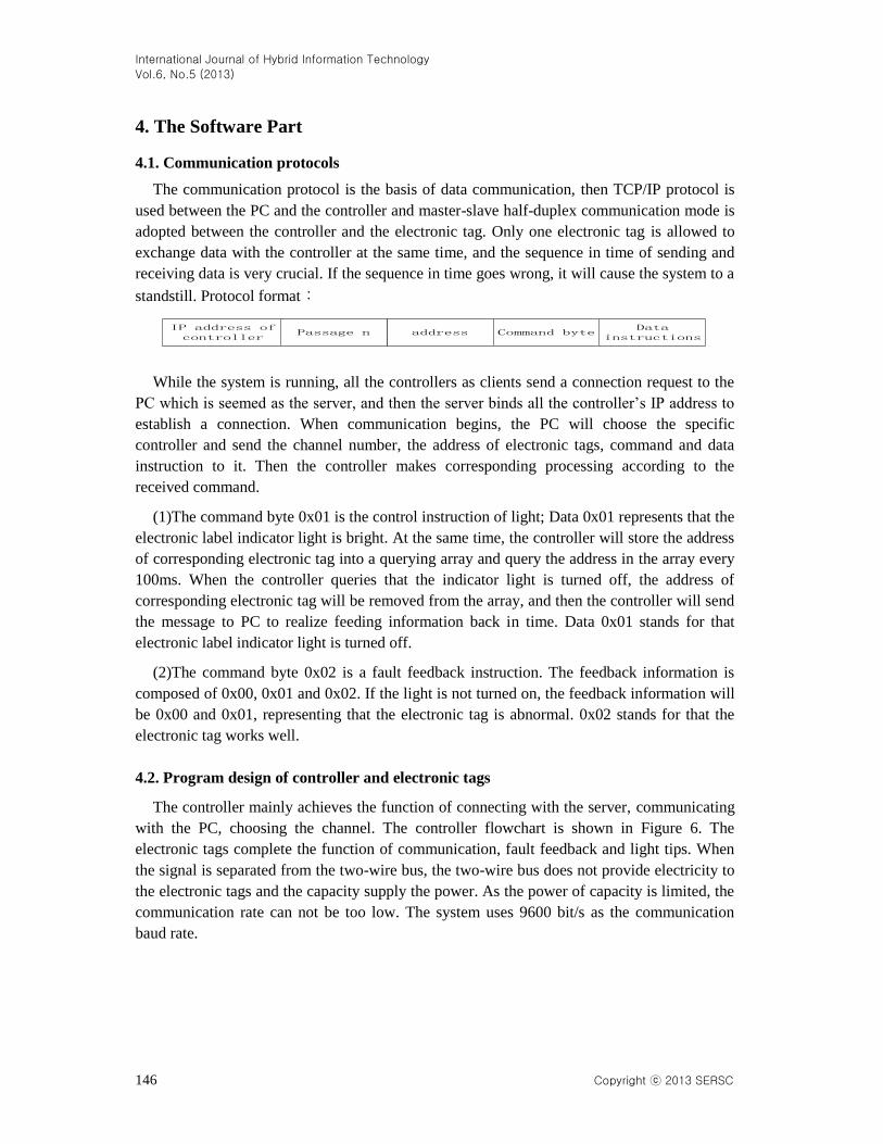
The communication protocol is the basis of data communication, then TCP/IP protocol is
used between the PC and the controller and master-slave half-duplex communication mode is
adopted between the controller and the electronic tag. Only one electronic tag is allowed to
exchange data with the controller at the same time, and the sequence in time of sending and
receiving data is very crucial. If the sequence in time goes wrong, it will cause the system to a
standstill. Protocol format:
addressData
instructionsCommand byte
IP address of controller
Passage n
While the system is running, all the controllers as clients send a connection request to the
PC which is seemed as the server, and then the server binds all the controller’s IP address to
establish a connection. When communication begins, the PC will choose the specific
controller and send the channel number, the address of electronic tags, command and data
instruction to it. Then the controller makes corresponding processing according to the
received command.
(1)The command byte 0x01 is the control instruction of light; Data 0x01 represents that the
electronic label indicator light is bright. At the same time, the controller will store the address
of corresponding electronic tag into a querying array and query the address in the array every
100ms. When the controller queries that the indicator light is turned off, the address of
corresponding electronic tag will be removed from the array, and then the controller will send
the message to PC to realize feeding information back in time. Data 0x01 stands for that
electronic label indicator light is turned off.
(2)The command byte 0x02 is a fault feedback instruction. The feedback information is
composed of 0x00, 0x01 and 0x02. If the light is not turned on, the feedback information will
be 0x00 and 0x01, representing that the electronic tag is abnormal. 0x02 stands for that the
electronic tag works well.
4.2. Program design of controller and electronic tags
The controller mainly achieves the function of connecting with the server, communicating
with the PC, choosing the channel. The controller flowchart is shown in Figure 6. The
electronic tags complete the function of communication, fault feedback and light tips. When
the signal is separated from the two-wire bus, the two-wire bus does not provide electricity to
the electronic tags and the capacity supply the power. As the power of capacity is limited, the
communication rate can not be too low. The system uses 9600 bit/s as the communication
baud rate.

International Journal of Hybrid Information Technology
Vol.6, No.5 (2013)
Copyright ⓒ 2013 SERSC 147
Connect to the server
Succeed?
Receive data?
Select the channel
Send an address frame
Match the address?
Send an order frame
The reset command
Command is correct?
Command categories
Send dataReceive data
Query array is empty?
The timing mark is 1?
Query the status of electronic tag
Remove obiect?
Remove the address from the
query array
N
Y
N
Y
Y
N
N
Y‘01’ ‘02’
NY
N
Y
N
Y
Begin
Add the address to the query array
Figure 6. Controller’s program flow chart
5. Experimental Results
As shown in Figure 7, the system is processing the orders come from the PC. The lower
right-hand corner of the figure is a waveform diagram of the two-wire bus. The blue
waveform is the one which modulated on the bus and the yellow waveform is the one which
demodulated by electronic tag. Experiments show that controller can stability control 120
electronic tags, and the system reaches the level of actual production needs.
Figure 7. Physical map of system
International Journal of Hybrid Information Technology
Vol.6, No.5 (2013)
148 Copyright ⓒ 2013 SERSC
6. Conclusions
It makes the sorting job simple using the computer to control the system. Using network
technology makes the system more convenient in extension. Three-channel is used as the
output of the controller to increase the load capacity. The introduction of TW two-wire bus
technology makes wiring easier on the shelves and save 50% of the conductive wire material.
References [1] Z. Su, X. Zou, Q. Liao and W. Yin, “Research on Pick-to-light Aided Sort”, Logistics Technology, no. 9,
(2005), pp. 51-53.
[2] C. Duan, J. Zhao and M. Li, “Research and design on warehousing electronic label picking system”,
Microcomputer & Its Applications, vol. 30, no. 11, (2011), pp. 116-118.
[3] Y. Wang, J. Li, B. Liu and L. Huo, “How to Design a New Electronic Tag Device for Logistics Picking”,
Logistics Technology, vol. 26, no. 8, (2007), pp. 188-189, 192.
[4] D. Feng and B. Li, “Application of electronic label in intelligent picking system”, HENAN SCIENCE, vol.
23, no. 2, (2005), pp. 285-288.
[5] C. Shen, X. Zou and Y. Wu, “Grid-Based Clustering Method Based on the Order of the Medical System and
the Electronic Tag Automatically Selected Systematic Comparative Study of Selected”, Logistics Sci-Tech,
vol. 34, no. 12, (2011), pp. 100-105.
[6] S. Lee and A. P. Ambler, “Cost Effective Test Planning for System-on-Chip Manufacture”, IEEE System
Readiness Technology Conference, (2006) September, pp. 86-92.
[7] J. Grover, R. D. Juncosa, N. Stoffel, M. Boysel, A. I. Brooks, M. P. McLoughlin and D. W. Robbins, “A
Stochastic Model of Human Machine Interaction for Learning Dialog Strategies”, IEEE SENSORS
JOURNAL, vol. 8, no. 5, (2008), pp. 476-487.
[8] M. Dotoli and M. P. Fanti, “Deadlock Detection and Avoidance Strategies for Automated Storage and
Retrieval Systems”, IEEE Trans. On Systems, Man, and Cybernetics, Part C: Applications and Reviews, vol.
37, no. 4, (2007), pp. 541-552.
[9] M. Dotoli, M. P. Fanti and G. Iacobellis, “Comparing deadlock detectionand avoidance policies in automated
storage and retrieval systems”, 2004 IEEE International Conference on Systems, Man and Cybernetics, vol. 2,
(2004), pp. 1607-1612.
[10] B. Abdelkrim, S. Zaki and G. Noureddine, “Performance analysis formulti-aisle automated storage/retrieval
systems using visual Petri netdeveloper”, 2003 IEEE International Symposium onComputationalIntelligence
in Robotics and Automation, vol. 3, (2003), pp. 1475-1481.
Authors
Feng Tian
He received the Ph.D. degree in detection technology and
automatic equipment from Northeastern University, China, in 2004.
He is currently professor at the College of Automation of Shenyang
Aerospace University. He is a member of CCF, and a doctoral tutor.
His current research focuses on wireless sensor networks, internet of
things, embedded systems and intelligent control.

International Journal of Hybrid Information Technology
Vol.6, No.5 (2013)
Copyright ⓒ 2013 SERSC 149
Tengfei Fu
He received the bachelor degree in electrical engineering and
automation from Yangzhou University, China, in 2011. He is currently
studying for a master degree in the College of Computer Science of
Shenyang Aerospace University.
Jing Fu
She received the master degree in management from Dongbei
University of Finance and Economics, China, in 2005.She is now
engaged in educational work in Shenyang.
International Journal of Hybrid Information Technology
Vol.6, No.5 (2013)
150 Copyright ⓒ 2013 SERSC
Copyright © 2022 FDOKUMEN