Interactive shear buckling behavior of trapezoidally corrugated steel webs
8
Engineering Structures 30 (2008) 1659–1666 www.elsevier.com/locate/engstruct Interactive shear buckling behavior of trapezoidally corrugated steel webs Jongwon Yi a , Heungbae Gil b , Kwangsoo Youm c , Hakeun Lee d,* a Institute of Construction Technology, Hyundai Engineering & Construction, 102-4, Mabuk-Dong, Giheung-Gu, Yongin-Si, Gyounggi-Do, 446-716, South Korea b Structural Engineering Research Team, Expressway & Transportation Research Institute, 50-5, Sancheok-Ri, Dongtan-Myun, Whaseong-Si, Gyeonggi-Do, 445-812, South Korea c Technical Division, GS Engineering & Construction, 417-1, Duksung-Ri, Eedong-Myun, Chuin-Gu, Yongin-Si, Gyounggi-Do, 449-831, South Korea d Department of Civil and Environmental Engineering, Korea University, 5-1, Anam-Dong, Sungbuk-Gu, Seoul, 136-701, South Korea Received 4 February 2006; received in revised form 6 November 2007; accepted 8 November 2007 Available online 21 February 2008 Abstract Trapezoidally corrugated steel plates have been used as the web of pre-stressed concrete box girder bridges to reduce dead load and increase structural efficiency. Due to an applied shear stress, the trapezoidally corrugated web can fail by three different shear buckling modes: local, global, and interactive shear buckling. Local buckling involves a single panel, whereas global buckling involves multiple panels, with buckles extending over the entire depth of the web. The interactive buckling is rather complex and is an intermediate type of shear buckling between local buckling and global buckling, which involves several panels. In this study, a series of finite element analyses was carried out to study the geometric parameters affecting interactive shear buckling modes and strength. Based on the analysis results, the interactive shear buckling strength formula is proposed. The proposed formula agreed well with the experimental data. c 2007 Elsevier Ltd. All rights reserved. Keywords: Corrugated web; Shear buckling; Interactive buckling; Shear strength; Finite element method 1. Introduction A trapezoidally corrugated steel plate is composed of a series of plane and inclined sub-panels, as shown in Fig. 1. The primary characteristics of the corrugated steel plates are negligible bending capacity and adequate out-of-plane stiffness. To take advantage of these characteristics, the corrugated steel plates have been considered as an alternative to conventional concrete or steel girder webs. When used as the web, the corrugated steel web carries the vertical shear, and the flanges carry the moment due to the accordion effect. Pre-stressed concrete box girder bridges with a corrugated steel web have been pioneered in France and extensively constructed in Japan. The first pre-stressed concrete box girder bridge with a corrugated web was recently constructed in South Korea. Research on the shear buckling behavior of corrugated plates has been initiated by Easley and McFarland [1]. Since then, numerous theoretical and experimental research on the buck- ling characteristics and strength of corrugated steel webs have * Corresponding author. Tel.: +82 2 3290 3315; fax: +82 2 928 5217. E-mail address: [email protected] (H. Lee). been performed by Elgaaly et al. [2–4] and Abbas et al. [5] in the United States and El-Metwally [6] and Sayed-Ahmed [7] in Canada. Studies have also been conducted by Cafolla [8] in Britain, Luo and Edlund [9] in Sweden, and Yoda et al. [10] and Yamazaki [11] in Japan. The studies on geometric parameters have been extensively carried out by Gil et al. [12,13] and Yi et al. [14]. Despite significant research, however, the shear buckling behavior of trapezoidally corrugated webs has not been clearly explained. Depending upon the geometric characteristics of the corrugated web, three different shear buckling modes, namely, local buckling, global buckling and interactive buckling are possible. Local buckling represents the buckling of a sub- panel, whereas global buckling is the buckling of the whole web. Interactive buckling, which involves a few sub-panels, occurs due to the interaction of local and global buckling. The previous research [14] shows that the buckling failure of the corrugated web is mainly governed by interactive shear buckling. However, the causes of interactive shear buckling have not been clearly defined, with much of the research conservatively underestimating the shear buckling strength. 0141-0296/$ - see front matter c 2007 Elsevier Ltd. All rights reserved. doi:10.1016/j.engstruct.2007.11.009
-
Upload
independent -
Category
Documents
-
view
2 -
download
0
Transcript of Interactive shear buckling behavior of trapezoidally corrugated steel webs
Engineering Structures 30 (2008) 1659–1666www.elsevier.com/locate/engstruct
Interactive shear buckling behavior of trapezoidally corrugated steel webs
Jongwon Yia, Heungbae Gilb, Kwangsoo Youmc, Hakeun Leed,∗
a Institute of Construction Technology, Hyundai Engineering & Construction, 102-4, Mabuk-Dong, Giheung-Gu, Yongin-Si, Gyounggi-Do, 446-716, South Koreab Structural Engineering Research Team, Expressway & Transportation Research Institute, 50-5, Sancheok-Ri, Dongtan-Myun, Whaseong-Si, Gyeonggi-Do,
445-812, South Koreac Technical Division, GS Engineering & Construction, 417-1, Duksung-Ri, Eedong-Myun, Chuin-Gu, Yongin-Si, Gyounggi-Do, 449-831, South Korea
d Department of Civil and Environmental Engineering, Korea University, 5-1, Anam-Dong, Sungbuk-Gu, Seoul, 136-701, South Korea
Received 4 February 2006; received in revised form 6 November 2007; accepted 8 November 2007Available online 21 February 2008
Abstract
Trapezoidally corrugated steel plates have been used as the web of pre-stressed concrete box girder bridges to reduce dead load and increasestructural efficiency. Due to an applied shear stress, the trapezoidally corrugated web can fail by three different shear buckling modes: local,global, and interactive shear buckling. Local buckling involves a single panel, whereas global buckling involves multiple panels, with bucklesextending over the entire depth of the web. The interactive buckling is rather complex and is an intermediate type of shear buckling between localbuckling and global buckling, which involves several panels. In this study, a series of finite element analyses was carried out to study the geometricparameters affecting interactive shear buckling modes and strength. Based on the analysis results, the interactive shear buckling strength formulais proposed. The proposed formula agreed well with the experimental data.c© 2007 Elsevier Ltd. All rights reserved.
Keywords: Corrugated web; Shear buckling; Interactive buckling; Shear strength; Finite element method
1. Introduction
A trapezoidally corrugated steel plate is composed of aseries of plane and inclined sub-panels, as shown in Fig. 1.The primary characteristics of the corrugated steel plates arenegligible bending capacity and adequate out-of-plane stiffness.To take advantage of these characteristics, the corrugated steelplates have been considered as an alternative to conventionalconcrete or steel girder webs. When used as the web, thecorrugated steel web carries the vertical shear, and the flangescarry the moment due to the accordion effect. Pre-stressedconcrete box girder bridges with a corrugated steel webhave been pioneered in France and extensively constructed inJapan. The first pre-stressed concrete box girder bridge with acorrugated web was recently constructed in South Korea.
Research on the shear buckling behavior of corrugated plateshas been initiated by Easley and McFarland [1]. Since then,numerous theoretical and experimental research on the buck-ling characteristics and strength of corrugated steel webs have
∗ Corresponding author. Tel.: +82 2 3290 3315; fax: +82 2 928 5217.E-mail address: [email protected] (H. Lee).
0141-0296/$ - see front matter c© 2007 Elsevier Ltd. All rights reserved.doi:10.1016/j.engstruct.2007.11.009
been performed by Elgaaly et al. [2–4] and Abbas et al. [5] inthe United States and El-Metwally [6] and Sayed-Ahmed [7]in Canada. Studies have also been conducted by Cafolla [8] inBritain, Luo and Edlund [9] in Sweden, and Yoda et al. [10] andYamazaki [11] in Japan. The studies on geometric parametershave been extensively carried out by Gil et al. [12,13] and Yiet al. [14].
Despite significant research, however, the shear bucklingbehavior of trapezoidally corrugated webs has not been clearlyexplained. Depending upon the geometric characteristics of thecorrugated web, three different shear buckling modes, namely,local buckling, global buckling and interactive buckling arepossible. Local buckling represents the buckling of a sub-panel, whereas global buckling is the buckling of the wholeweb. Interactive buckling, which involves a few sub-panels,occurs due to the interaction of local and global buckling.The previous research [14] shows that the buckling failure ofthe corrugated web is mainly governed by interactive shearbuckling. However, the causes of interactive shear bucklinghave not been clearly defined, with much of the researchconservatively underestimating the shear buckling strength.
1660 J. Yi et al. / Engineering Structures 30 (2008) 1659–1666
Nomenclature
a flat panel widthb horizontal projection of the inclined panel widthc inclined panel widthd corrugation depthh web heightθ corrugation angleτ E
cr,L elastic local shear buckling stressE Young’s modulus of elasticityν Poisson’s ratiot web thicknessk local shear buckling coefficientτ E
cr,G elastic global shear buckling stressβ global shear buckling coefficientDx longitudinal bending stiffness per unit length of
the corrugated webDy transverse bending stiffness per unit length of the
corrugated webIx moment of inertia about the axis along web heightIy moment of inertia about the neutral axis along
web heightτcr,I critical interactive shear buckling stressτcr,L critical local shear buckling stressτcr,G critical global shear buckling stressτy shear yielding stressη length reduction factor = (a + b)/(a + c)τ f e shear buckling stress from numerical analysis
resultsτcr critical shear buckling stressλs shear buckling parameterτ E
cr,I elastic interactive shear buckling stressτex shear buckling stress from test resultsCL coefficient unrelated with geometric parameters
for simplified local shear buckling stressCG coefficient unrelated with geometric parameters
for simplified global shear buckling stressC I = CG/CL
Fig. 1. Trapezoidally corrugated web.
In this paper, the interactive buckling behavior of corrugatedsteel webs was investigated. Geometric parameters, whichaffect the buckling mode, were first derived from local andglobal buckling formulas. To study the effects of derived
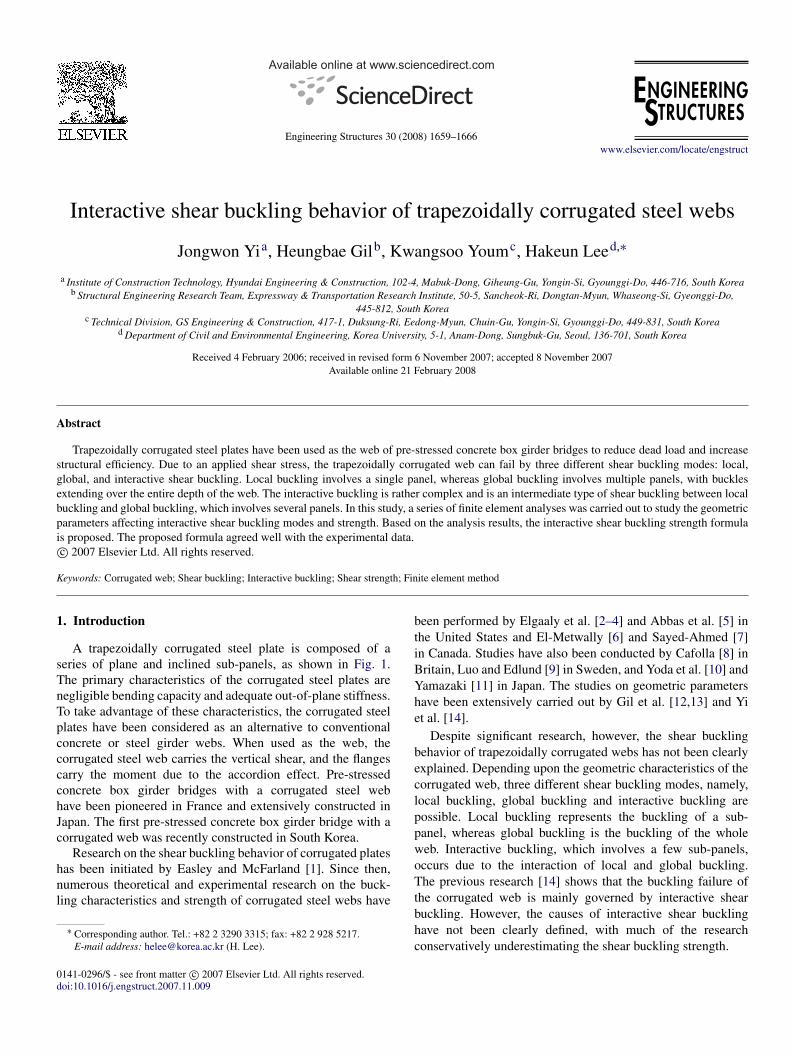
Fig. 2. Local shear buckling mode.
parameters on interactive buckling modes, an elastic bifurcationbuckling analysis and a nonlinear analysis consideringgeometric and material nonlinearities were performed usingthree-dimensional finite element models of corrugated webs.The analysis results were also used to propose an interactivebuckling strength formula. The proposed formula was verifiedusing the experimental data from the literature.
2. Shear buckling behavior of corrugated webs
2.1. Shear buckling mode
Local buckling occurs when a flat sub-plate between verticaledges has a large width to thickness ratio as shown in Fig. 2.The buckling strength equation is taken from the classical platebuckling theory [15] as follows:
τ Ecr,L = k ×
π2 E
12(1 − ν2)
(t
a
)2
, (1)
where E = Young’s modulus of elasticity, ν = Poisson’s ratio,a = the maximum width of a flat or inclined fold, t = the webthickness, and k = the buckling coefficient defined according tothe boundary conditions and aspect ratio of the sub-panel.
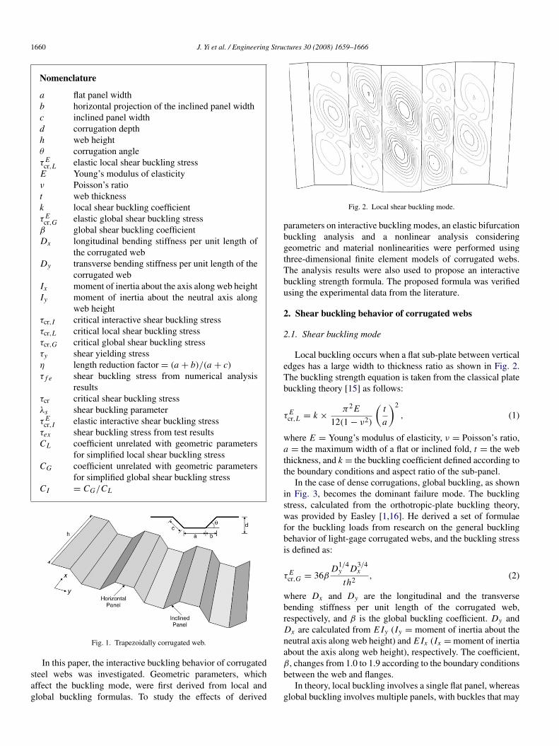
In the case of dense corrugations, global buckling, as shownin Fig. 3, becomes the dominant failure mode. The bucklingstress, calculated from the orthotropic-plate buckling theory,was provided by Easley [1,16]. He derived a set of formulaefor the buckling loads from research on the general bucklingbehavior of light-gage corrugated webs, and the buckling stressis defined as:
τ Ecr,G = 36β
D1/4y D3/4
x
th2 , (2)
where Dx and Dy are the longitudinal and the transversebending stiffness per unit length of the corrugated web,respectively, and β is the global buckling coefficient. Dy andDx are calculated from E Iy (Iy = moment of inertia about theneutral axis along web height) and E Ix (Ix = moment of inertiaabout the axis along web height), respectively. The coefficient,β, changes from 1.0 to 1.9 according to the boundary conditionsbetween the web and flanges.
In theory, local buckling involves a single flat panel, whereasglobal buckling involves multiple panels, with buckles that may
J. Yi et al. / Engineering Structures 30 (2008) 1659–1666 1661
Table 1Interactive shear buckling strengths
Researcher Interactive shear buckling strength Remarks
Bergfelt [18](
1τcr,I
)=
(1
τ Ecr,L
)+
(1
τ Ecr,G
)The material inelasticity and yielding are not considered.
El-Metwally [6](
1τcr,I
)2=
(1
τ Ecr,L
)2
+
(1
τ Ecr,G
)2
+
(1τy
)2
Sayed-Ahmed [19](
1τcr,I
)3=
(1
τ Ecr,L
)3
+
(1
τ Ecr,G
)3
+
(1τy
)3
Abbas [5](
1τcr,I
)2=
(1
τcr,L
)2+
(1
τcr,G
)2
The yielding of material can be considered using inelastic buckling strength.
Hiroshi [20](
1τcr,I
)4=
(1
τcr,L
)4+
(1
τcr,G
)4
Design manual [21] Corrugated web is designed to have no local and global buckling as well as interactive buckling failure.
Fig. 3. Global shear buckling mode.
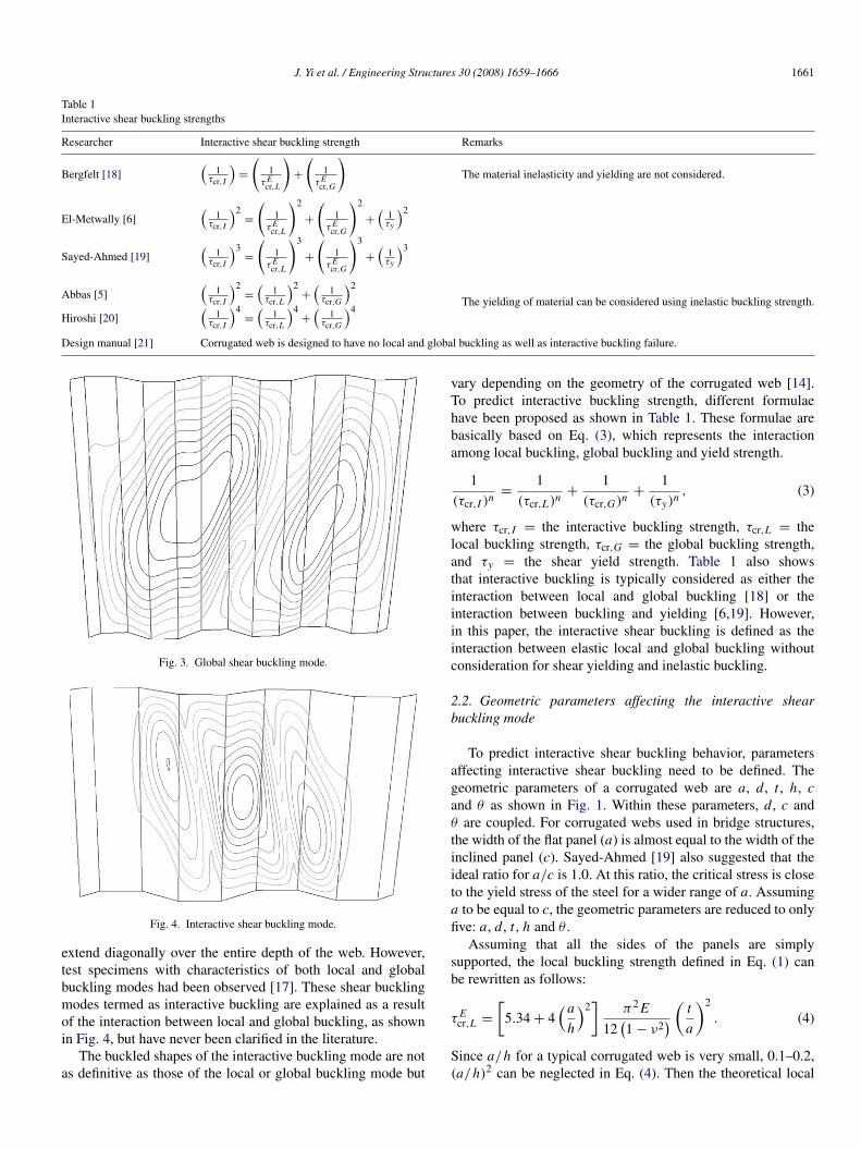
Fig. 4. Interactive shear buckling mode.
extend diagonally over the entire depth of the web. However,test specimens with characteristics of both local and globalbuckling modes had been observed [17]. These shear bucklingmodes termed as interactive buckling are explained as a resultof the interaction between local and global buckling, as shownin Fig. 4, but have never been clarified in the literature.
The buckled shapes of the interactive buckling mode are notas definitive as those of the local or global buckling mode but
vary depending on the geometry of the corrugated web [14].To predict interactive buckling strength, different formulaehave been proposed as shown in Table 1. These formulae arebasically based on Eq. (3), which represents the interactionamong local buckling, global buckling and yield strength.
1(τcr,I )n =
1(τcr,L)n +
1(τcr,G)n +
1(τy)n , (3)
where τcr,I = the interactive buckling strength, τcr,L = thelocal buckling strength, τcr,G = the global buckling strength,and τy = the shear yield strength. Table 1 also showsthat interactive buckling is typically considered as either theinteraction between local and global buckling [18] or theinteraction between buckling and yielding [6,19]. However,in this paper, the interactive shear buckling is defined as theinteraction between elastic local and global buckling withoutconsideration for shear yielding and inelastic buckling.
2.2. Geometric parameters affecting the interactive shearbuckling mode
To predict interactive shear buckling behavior, parametersaffecting interactive shear buckling need to be defined. Thegeometric parameters of a corrugated web are a, d, t , h, cand θ as shown in Fig. 1. Within these parameters, d, c andθ are coupled. For corrugated webs used in bridge structures,the width of the flat panel (a) is almost equal to the width of theinclined panel (c). Sayed-Ahmed [19] also suggested that theideal ratio for a/c is 1.0. At this ratio, the critical stress is closeto the yield stress of the steel for a wider range of a. Assuminga to be equal to c, the geometric parameters are reduced to onlyfive: a, d, t , h and θ .
Assuming that all the sides of the panels are simplysupported, the local buckling strength defined in Eq. (1) canbe rewritten as follows:
τ Ecr,L =
[5.34 + 4
(a
h
)2]
π2 E
12(1 − ν2
) ( t
a
)2
. (4)
Since a/h for a typical corrugated web is very small, 0.1–0.2,(a/h)2 can be neglected in Eq. (4). Then the theoretical local

1662 J. Yi et al. / Engineering Structures 30 (2008) 1659–1666
shear buckling strength becomes:
τ Ecr,L =
5.34π2 E
12(1 − ν2
) ( t
a
)2
. (5)
The global buckling strength given in Eq. (2) can also beexpressed as follows:
τ Ecr,G = 36βE
1[12(1 − υ2
)]1/4
[(d/t)2
+ 16η
]3/4 (t
h
)2
, (6)
where η =a+ba+c . The corrugation angle of bridges, θ , is
typically about 25◦–35◦, and when a is equal to c, the variableη can be considered constant because the changes in η are lessthan 5%. When d/t is larger than 8.66, the theoretical globalshear buckling strength can be simplified with less than 1%difference as given below:
τ Ecr,G = CG
(d
t
)1.5 ( t
h
)2
, (7)
where CG is a constant and is defined as CG =5.045βE
(1−υ2)1/4
(η)3/4 .
Previous studies [14] have shown that interactive shearbuckling is affected by the ratio of the elastic local and globalbuckling strengths. The ratio can be arranged as follows:
τ Ecr,G
τ Ecr,L
= C I
(a
h
)2(
d
t
)1.5
, (8)
where
C I =CG
CL=
36βE 1
[12(1−υ2)]1/41
(6η)3/4
5.34 π2 E12(1−υ2)
= 0.6813β
[2(1 − υ2
)η
]3/4
.
The coefficient, C I , has only one geometric parameter, η,which is almost constant as shown earlier. Therefore, it canbe concluded that the interactive shear buckling strength isaffected only by the geometric parameters a/h and d/t . Inthe following chapter, the effects of the relationship betweeninteractive shear buckling and the two geometric parameters,a/h and d/t , is studied through finite element analysis.
3. Finite element analysis
Bifurcation buckling analysis, using the finite elementmethod, was first performed to determine the elastic shearbuckling strength of the corrugated web and to investigatethe geometric parameters affecting interactive shear bucklingmodes and strength. Next, a nonlinear finite element analysis,which considered both the geometric and the materialnonlinearities, was carried out to verify the proposed theoreticalbuckling formulae.
Fig. 5. Shear buckling analysis model.
Table 2Boundary conditions of the analytical model
AB BC CD DA
Translation X (1) R F R FY (2) R R R RZ (3) F F F R
Rotation X (1) F F F FY (2) F R F FZ (3) F R F F
F: Free, R: Restrained.
3.1. Finite element analysis modeling
Previous analytical studies typically used the girder withflanges and stiffeners to examine the buckling behavior ofcorrugated web plates [2,5,10,12]. However, the effects of theflange and stiffeners on the shear behavior of a corrugated webcould not be completely ignored in these models. It was alsodifficult to confirm the shear behavior of a pure corrugated web.In this study, a corrugated web plate was only modeled.
The analytical model shown in Fig. 5 was built using thegeneral-purpose finite element program, ABAQUS [22]. Inthe construction of the model, the following conditions wereconsidered.
– Modeling under shear load (boundary and loading condi-tions).
– Number of elements per panel.– Influence of the overall dimension (h and L).– State of pure shear.
S8R5 reduced integration thin shell elements were used tomodel the corrugated plate. The flange and stiffeners weremodeled as simply support boundary conditions as given inTable 2. In order to minimize the computational effort withoutsacrificing the accuracy of the results, the model used fourelements per panel, and the number of corrugation cyclesdetermined for the ratio, L/h, was kept greater than two. Loadwas applied at the BC edge in three directions, as in Fig. 5.The pure shear state of the web panel under the defined loadingand boundary conditions were checked by static analysis of themodel.
To verify the analytical model, shear buckling analysesof a flat plate were first conducted under the boundary and
J. Yi et al. / Engineering Structures 30 (2008) 1659–1666 1663
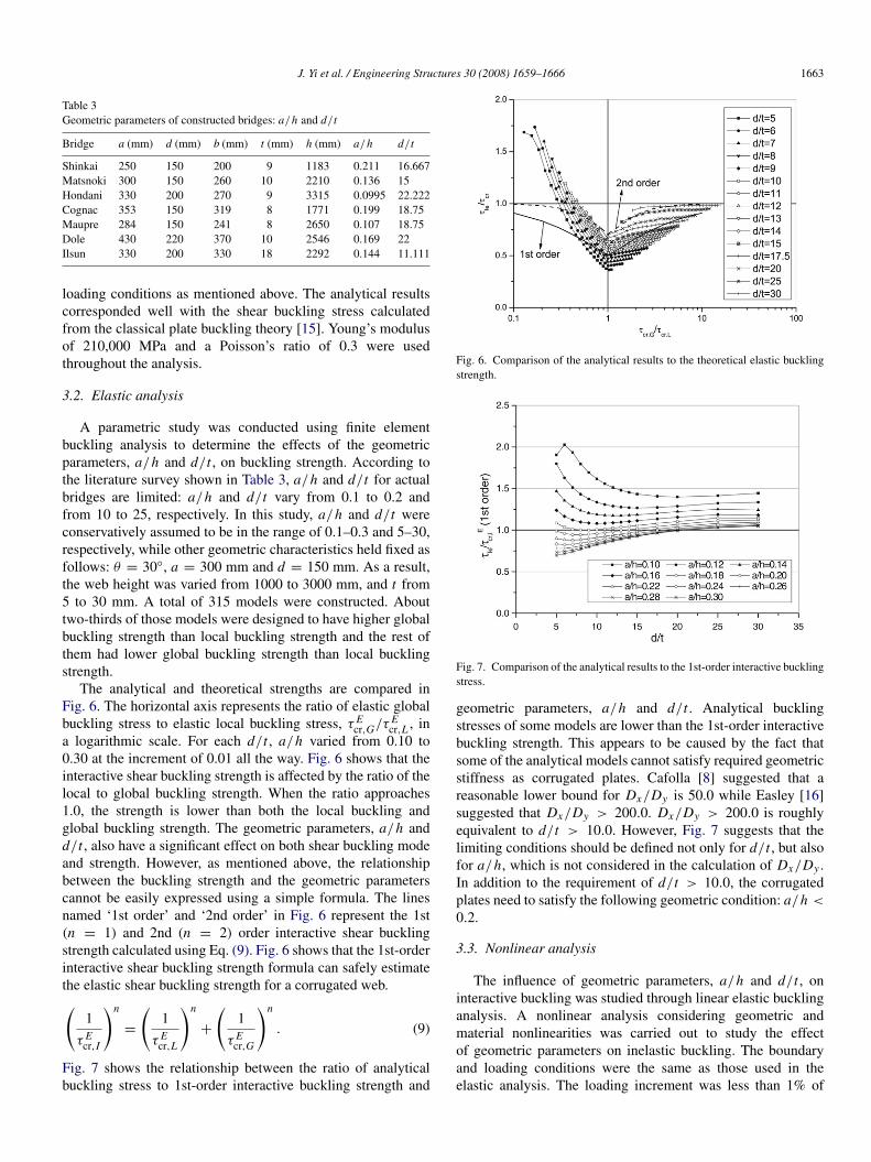
Table 3Geometric parameters of constructed bridges: a/h and d/t
Bridge a (mm) d (mm) b (mm) t (mm) h (mm) a/h d/t
Shinkai 250 150 200 9 1183 0.211 16.667Matsnoki 300 150 260 10 2210 0.136 15Hondani 330 200 270 9 3315 0.0995 22.222Cognac 353 150 319 8 1771 0.199 18.75Maupre 284 150 241 8 2650 0.107 18.75Dole 430 220 370 10 2546 0.169 22Ilsun 330 200 330 18 2292 0.144 11.111
loading conditions as mentioned above. The analytical resultscorresponded well with the shear buckling stress calculatedfrom the classical plate buckling theory [15]. Young’s modulusof 210,000 MPa and a Poisson’s ratio of 0.3 were usedthroughout the analysis.
3.2. Elastic analysis
A parametric study was conducted using finite elementbuckling analysis to determine the effects of the geometricparameters, a/h and d/t , on buckling strength. According tothe literature survey shown in Table 3, a/h and d/t for actualbridges are limited: a/h and d/t vary from 0.1 to 0.2 andfrom 10 to 25, respectively. In this study, a/h and d/t wereconservatively assumed to be in the range of 0.1–0.3 and 5–30,respectively, while other geometric characteristics held fixed asfollows: θ = 30◦, a = 300 mm and d = 150 mm. As a result,the web height was varied from 1000 to 3000 mm, and t from5 to 30 mm. A total of 315 models were constructed. Abouttwo-thirds of those models were designed to have higher globalbuckling strength than local buckling strength and the rest ofthem had lower global buckling strength than local bucklingstrength.
The analytical and theoretical strengths are compared inFig. 6. The horizontal axis represents the ratio of elastic globalbuckling stress to elastic local buckling stress, τ E
cr,G/τ Ecr,L , in
a logarithmic scale. For each d/t , a/h varied from 0.10 to0.30 at the increment of 0.01 all the way. Fig. 6 shows that theinteractive shear buckling strength is affected by the ratio of thelocal to global buckling strength. When the ratio approaches1.0, the strength is lower than both the local buckling andglobal buckling strength. The geometric parameters, a/h andd/t , also have a significant effect on both shear buckling modeand strength. However, as mentioned above, the relationshipbetween the buckling strength and the geometric parameterscannot be easily expressed using a simple formula. The linesnamed ‘1st order’ and ‘2nd order’ in Fig. 6 represent the 1st(n = 1) and 2nd (n = 2) order interactive shear bucklingstrength calculated using Eq. (9). Fig. 6 shows that the 1st-orderinteractive shear buckling strength formula can safely estimatethe elastic shear buckling strength for a corrugated web.(
1
τ Ecr,I
)n
=
(1
τ Ecr,L
)n
+
(1
τ Ecr,G
)n
. (9)
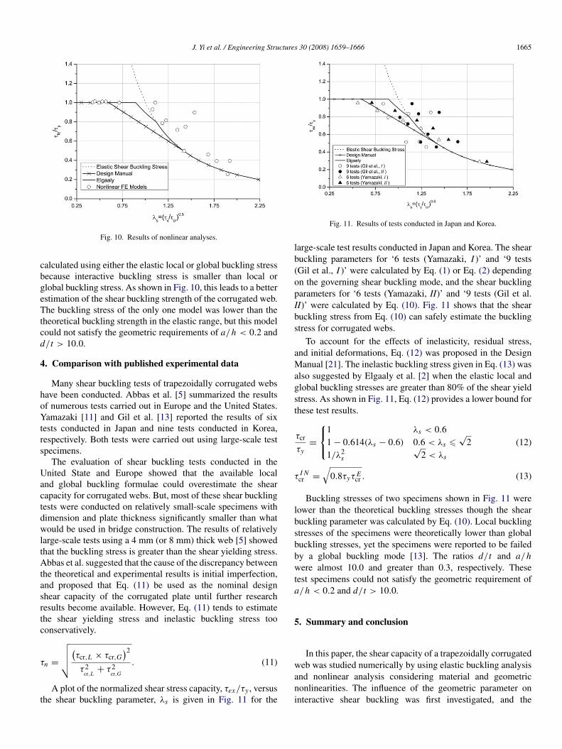
Fig. 7 shows the relationship between the ratio of analyticalbuckling stress to 1st-order interactive buckling strength and
Fig. 6. Comparison of the analytical results to the theoretical elastic bucklingstrength.
Fig. 7. Comparison of the analytical results to the 1st-order interactive bucklingstress.
geometric parameters, a/h and d/t . Analytical bucklingstresses of some models are lower than the 1st-order interactivebuckling strength. This appears to be caused by the fact thatsome of the analytical models cannot satisfy required geometricstiffness as corrugated plates. Cafolla [8] suggested that areasonable lower bound for Dx/Dy is 50.0 while Easley [16]suggested that Dx/Dy > 200.0. Dx/Dy > 200.0 is roughlyequivalent to d/t > 10.0. However, Fig. 7 suggests that thelimiting conditions should be defined not only for d/t , but alsofor a/h, which is not considered in the calculation of Dx/Dy .In addition to the requirement of d/t > 10.0, the corrugatedplates need to satisfy the following geometric condition: a/h <
0.2.
3.3. Nonlinear analysis
The influence of geometric parameters, a/h and d/t , oninteractive buckling was studied through linear elastic bucklinganalysis. A nonlinear analysis considering geometric andmaterial nonlinearities was carried out to study the effectof geometric parameters on inelastic buckling. The boundaryand loading conditions were the same as those used in theelastic analysis. The loading increment was less than 1% of

1664 J. Yi et al. / Engineering Structures 30 (2008) 1659–1666
Fig. 8. Material property for the nonlinear analysis.
Table 4Geometric properties of the nonlinear analysis models
No. a/h d/t τ f e/τcr(Elasticanalysisresults)
τ Ecr,L
(Theory)
τ Ecr,G
(Theory)
τ Ecr,G
τ Ecr,L
y-10.11 6.0 1.532
3577.66 707.09 0.198i-1 724.48 140.20 0.194e-1 377.89 72.95 0.193
y-20.15 8.0 0.738
2225.71 1241.97 0.558i-2 272.65 148.32 0.544e-2 144.21 78.32 0.543
y-30.29 25.0 0.947
780.84 9249.49 11.846i-3 135.56 1459.80 10.768e-3 86.76 928.80 10.705
y-40.18 15.0 0.713
762.88 1558.99 2.044i-4 154.48 306.91 1.987e-4 68.66 135.90 1.979
y-50.22 7.0 0.442
918.52 870.83 0.948i-5 146.96 138.33 0.941e-5 82.67 77.76 0.941
y-60.11 17.5 0.667
572.43 559.08 0.977i-6 143.11 135.95 0.950e-6 80.50 76.18 0.946
the ultimate load. The tri-linear elastic–plastic stress–strainrelationship shown in Fig. 8 was used in the nonlinear analysis.
A total of 18 analytical models described in Table 4 weredeveloped by combining six different a/h and d/t ratios.The first two combinations of a/h and d/t were designedto be governed by local buckling while the third and forthcombinations were governed by global buckling. The modelsfrom the remaining two combinations had lower interactivebuckling stress than either local or global buckling stress. Themodels also had different ratios of buckling stress to yieldstress. The elastic buckling stresses of ‘y’ series models weremuch higher than the material yielding stress. The ‘i’ seriesmodels had elastic buckling stresses similar to the material yieldstress. The elastic buckling stresses of the ‘e’ series modelswere about 50% of the material yield stress.
The buckling stresses from nonlinear analyses werecompared to the theoretical interactive buckling strengths in
Fig. 9. Comparison of the nonlinear analytical results to the interactivebuckling strengths.
Fig. 9. The horizontal axis represents the shear bucklingparameter, λs , which is calculated using the buckling stress ofthe governing buckling mode. The analysis results were not ingood agreement with the theoretical strength. This is becausethe available formulae for interactive shear buckling strengthsare not derived to theoretically explain the interactive shearbuckling phenomena, but are derived to simply provide smallerfailure loads than predicted by local and global buckling modes.
The models in the yielding zone in Fig. 9 are the ‘y’ seriesmodels, which were designed to fail by material yielding,and the buckling stress of those models was conservativelypredicted from existing formula. The buckling stress formulaesuggested by Hiroshi et al. [20] and Abbas et al. [5] weretoo conservative in their predictions. For the ‘i’ series models,there were only small differences between critical bucklingstresses calculated by the different formulae, but the predictionof the shear buckling strength was less accurate. For themodels whose buckling stress is less influenced by interactivebuckling, shear buckling strength was predicted conservatively,irrespective of buckling formulae. The predictions for thestrength of the models governed by the global buckling modewere too conservative, while the strength of the models witha large strength reduction due to interactive shear bucklingwas overestimated. This tendency became more obvious in theelastic region. These results indicate that the existing formulaefor interactive shear buckling cannot clearly describe interactiveshear buckling phenomena nor predict the shear strength.
Results from the nonlinear finite elements analysis results,along with theoretical buckling stresses, are plotted as afunction of the shear buckling parameter, λs , in Fig. 10.The parameter λs and the theoretical buckling stresses werecalculated using the elastic 1st-order interactive shear bucklingstrength, τ E
cr,I , defined in Eq. (10).
τ Ecr,I =
τ Ecr,L × τ E
cr,G
τ Ecr,L + τ E
cr,G
. (10)
The shear buckling parameters calculated using the elasticinteractive buckling stress of Eq. (10) are greater than ones
J. Yi et al. / Engineering Structures 30 (2008) 1659–1666 1665
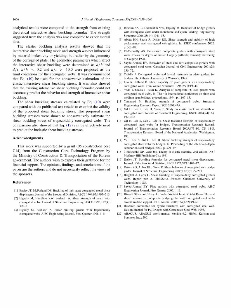
Fig. 10. Results of nonlinear analyses.
calculated using either the elastic local or global buckling stressbecause interactive buckling stress is smaller than local orglobal buckling stress. As shown in Fig. 10, this leads to a betterestimation of the shear buckling strength of the corrugated web.The buckling stress of the only one model was lower than thetheoretical buckling strength in the elastic range, but this modelcould not satisfy the geometric requirements of a/h < 0.2 andd/t > 10.0.
4. Comparison with published experimental data
Many shear buckling tests of trapezoidally corrugated webshave been conducted. Abbas et al. [5] summarized the resultsof numerous tests carried out in Europe and the United States.Yamazaki [11] and Gil et al. [13] reported the results of sixtests conducted in Japan and nine tests conducted in Korea,respectively. Both tests were carried out using large-scale testspecimens.
The evaluation of shear buckling tests conducted in theUnited State and Europe showed that the available localand global buckling formulae could overestimate the shearcapacity for corrugated webs. But, most of these shear bucklingtests were conducted on relatively small-scale specimens withdimension and plate thickness significantly smaller than whatwould be used in bridge construction. The results of relativelylarge-scale tests using a 4 mm (or 8 mm) thick web [5] showedthat the buckling stress is greater than the shear yielding stress.Abbas et al. suggested that the cause of the discrepancy betweenthe theoretical and experimental results is initial imperfection,and proposed that Eq. (11) be used as the nominal designshear capacity of the corrugated plate until further researchresults become available. However, Eq. (11) tends to estimatethe shear yielding stress and inelastic buckling stress tooconservatively.
τn =
√√√√(τcr,L × τcr,G
)2τ 2
cr,L+ τ 2
cr,G
. (11)
A plot of the normalized shear stress capacity, τex/τy , versusthe shear buckling parameter, λs is given in Fig. 11 for the
Fig. 11. Results of tests conducted in Japan and Korea.
large-scale test results conducted in Japan and Korea. The shearbuckling parameters for ‘6 tests (Yamazaki, I )’ and ‘9 tests(Gil et al., I )’ were calculated by Eq. (1) or Eq. (2) dependingon the governing shear buckling mode, and the shear bucklingparameters for ‘6 tests (Yamazaki, II)’ and ‘9 tests (Gil et al.II)’ were calculated by Eq. (10). Fig. 11 shows that the shearbuckling stress from Eq. (10) can safely estimate the bucklingstress for corrugated webs.
To account for the effects of inelasticity, residual stress,and initial deformations, Eq. (12) was proposed in the DesignManual [21]. The inelastic buckling stress given in Eq. (13) wasalso suggested by Elgaaly et al. [2] when the elastic local andglobal buckling stresses are greater than 80% of the shear yieldstress. As shown in Fig. 11, Eq. (12) provides a lower bound forthese test results.
τcr
τy=
1 λs < 0.61 − 0.614(λs − 0.6) 0.6 < λs 6
√2
1/λ2s
√2 < λs
(12)
τ I Ncr =
√0.8τyτ E
cr . (13)
Buckling stresses of two specimens shown in Fig. 11 werelower than the theoretical buckling stresses though the shearbuckling parameter was calculated by Eq. (10). Local bucklingstresses of the specimens were theoretically lower than globalbuckling stresses, yet the specimens were reported to be failedby a global buckling mode [13]. The ratios d/t and a/hwere almost 10.0 and greater than 0.3, respectively. Thesetest specimens could not satisfy the geometric requirement ofa/h < 0.2 and d/t > 10.0.
5. Summary and conclusion
In this paper, the shear capacity of a trapezoidally corrugatedweb was studied numerically by using elastic buckling analysisand nonlinear analysis considering material and geometricnonlinearities. The influence of the geometric parameter oninteractive shear buckling was first investigated, and the
1666 J. Yi et al. / Engineering Structures 30 (2008) 1659–1666
analytical results were compared to the strength from existingtheoretical interactive shear buckling formulae. The strengthsuggested from the analysis was also compared to experimentaldata.
The elastic buckling analysis results showed that theinteractive shear buckling mode and strength was not influencedby material inelasticity or yielding, but rather by the geometryof the corrugated plate. The geometric parameters which affectthe interactive shear buckling were determined as a/h andd/t . a/h < 0.2 and d/t > 10.0 were proposed as thelimit conditions for the corrugated webs. It was recommendedthat Eq. (10) be used for the conservative estimation of theelastic interactive shear buckling stress. It was also showedthat the existing interactive shear buckling formulae could notaccurately predict the behavior and strength of interactive shearbuckling.
The shear buckling stresses calculated by Eq. (10) werecompared with the published test results to examine the validityof the proposed shear buckling stress. The proposed shearbuckling stresses were shown to conservatively estimate theshear buckling stress of trapezoidally corrugated webs. Thecomparison also showed that Eq. (12) can be effectively usedto predict the inelastic shear buckling stresses.
Acknowledgments
This work was supported by a grant (05 construction coreC14) from the Construction Core Technology Program bythe Ministry of Construction & Transportation of the Koreangovernment. The authors wish to express their gratitude for thefinancial support. The opinions, findings, and conclusions of thepaper are the authors and do not necessarily reflect the views ofthe sponsors.
References
[1] Easley JT, McFarland DE. Buckling of light-gage corrugated metal sheardiaphragms. Journal of the Structural Division, ASCE 1969;95:1497–516.
[2] Elgaaly M, Hamilton RW, Seshadri A. Shear strength of beam withcorrugated webs. Journal of Structural Engineering, ASCE 1996;122(4):390–8.
[3] Elgaaly M, Seshadri A. Shear built-up girders with trapezoidallycorrugated webs. AISC Engineering Journal, First Quarter 1998;1–11.
[4] Ibrahim SA, El-Dakhakhni VW, Elgaaly M. Behavior of bridge girderswith corrugated webs under monotonic and cyclic loading. EngineeringStructures 2006;28(14):1941–55.
[5] Abbas HH, Sause R, Driver RG. Shear strength and stability of highperformance steel corrugated web girders. In: SSRC conference. 2002.p. 361–87.
[6] El-Metwally AS. Prestressed composite girders with corrugated steelwebs. Thesis for degree of master. Calgary (Alberta, Canada): Universityof Calgary; 1998.
[7] Sayed-Ahmed EY. Behavior of steel and (or) composite girders withcorrugated steel webs. Canadian Journal of Civil Engineering 2001;28:656–72.
[8] Cafolla J. Corrugated webs and lateral restraints in plate girders forbridges. Ph.D. thesis. University of Warwick; 1995.
[9] Luo R, Edlund B. Shear capacity of plate girders with trapezoidallycorrugated webs. Thin Walled Structures 1996;26(1):19–44.
[10] Yoda T, Ohura T, Sekii K. Analysis of composite PC Box girders withcorrugated steel webs. In: The 4th international conference on short andmedium span bridges, proceedings. 1994. p. 1107–15.
[11] Yamazaki M. Buckling strength of corrugated webs. StructuralEngineering Research Paper, JSCE 2001;47A.
[12] Gil H, Lee S, Lee H, Yoon T. Study on elastic buckling strength ofcorrugated web. Journal of Structural Engineering, KSCE 2004;24(1A):192–202.
[13] Gil H, Lee S, Lee J, Lee H. Shear buckling strength of trapezoidallycorrugated steel webs for bridges. Transportation Research Record:Journal of Transportation Research Board 2005;473–80. CD 11-S,Transportation Research Board of the National Academies, Washington,DC.
[14] Yi J, Lee S, Gil H, Lee H. Shear buckling strength of trapezoidallycorrugated steel webs for bridges. In: Proceeding of the 7th Korea–Japanseminar on steel bridges. 2003. p. 329–39.
[15] Timoshenko SP, Gere JM. Theory of elastic stability. 2nd edition. NY:McGraw-Hill Publishing Co.; 1961.
[16] Easley JT. Buckling formulas for corrugated metal shear diaphragms.Journal of the Structural Division, SECF 1975;ST7:1403–17.
[17] Driver RG, Abbas HH, Sause R. Shear behavior of corrugated web bridgegirder. Journal of Structural Engineering 2006;132(2):195–203.
[18] Bergfelt A, Leiva L. Shear buckling of trapezoidally corrugated girderswebs. Report part 2. Pibl.SS4:2. Sweden: Chalmers University ofTechnology; 1984.
[19] Sayed-Ahmed EY. Plate girders with corrugated steel webs. AISCEngineering Journal, First Quarter 2005;1–13.
[20] Hiroshi Shiratoni, Hiroyuki Ikeda, Yohiaki Imai, Koichi Kano. Flexuralshear behavior of composite bridge girder with corrugated steel websaround middle support. JSCE Journal 2003;724(I-62):49–67.
[21] Research committee for hybrid structures with corrugated steel web.Design Manual for PC Bridges with Corrugated Steel Web. 1998.
[22] ABAQUS. ABAQUS user’s manual version 6.2. Hibbit, Karlson andSorenson Inc.; 2001.