Numerical Study and Geometric Investigation of Corrugated ...
12
J. Appl. Comput. Mech., 7(2) (2021) 727-738 DOI: 10.22055/JACM.2020.35345.2634 ISSN: 2383-4536 jacm.scu.ac.ir Published online: December 15 2020 Numerical Study and Geometric Investigation of Corrugated Channels Subjected to Forced Convective Flows Rafael San Martin Moreira 1 , Cícero Coelho de Escobar 2 , Liércio André Isoldi 3 , Rodrigo Rocha Davesac 4 , Luiz Alberto Oliveira Rocha 5 , Elizaldo Domingues dos Santos 6 1 Graduate Program in Ocean Engineering, Federal University of Rio Grande – FURG, Av. Itália, km 8, 96203-900 Rio Grande, RS, Brazil, Email: [email protected] 2 Environmental and Sanitary Engineering, Engineering Center, UFPel, Pelotas, RS, Brazil, Email: [email protected] 3 Graduate Program in Ocean Engineering, Federal University of Rio Grande – FURG, Av. Itália, km 8, 96203-900 Rio Grande, RS, Brazil, Email: [email protected] 4 School of Engineering, Federal University of Rio Grande – FURG, Italia Av., km 8, 96203-900 Rio Grande, RS, Brazil, Email: [email protected] 5 University of the Valley of Bells River (Unisinos), Department of Mechanical Engineering, 950 Unisinos Av., São Leopoldo, 93022-750, Brazil, Email: [email protected] 6 Graduate Program in Computational Modeling, Federal University of Rio Grande – FURG, Av. Itália, km 8, 96203-900 Rio Grande, RS, Brazil, Email: [email protected] Received October 08 2020; Revised December 13 2020; Accepted for publication December 14 2020. Corresponding author: Elizaldo Domingues dos Santos ([email protected]) © 2020 Published by Shahid Chamran University of Ahvaz Abstract. The employment of heat exchangers with complex channels has increasing importance in several engineering problems as commercial refrigeration and cooling of electronic packages. One important subject in this kind of device is the design of corrugated channels. Therefore, the present work aims at the geometric optimization of trapezoidal blocks mounted in channels subjected to steady, incompressible, laminar, two-dimensional forced convective flows. The computational domain studied here mimics the corrugated channels commonly found in micro-channel heat exchangers. For the geometrical investigation, it is employed the Constructal Design Method. The numerical simulations were performed for two Reynolds numbers (ReH) equal to 60 and 160 and constant Prandtl number (Pr = 6.99). Results demonstrated that the length/height ratios of both studied blocks (given by L1/H1 and L2/H2 ratios) have the highest sensibility over the thermal performance, showing the importance of the channel's blocks intrusion. It was also shown that the combined analysis of the ratios L1/H1 and L2/H2 was much more efficient for the improvement of the heat transfer rate in the corrugated channels. The thermal performance increased by nearly 65% when the best and worst configurations were compared. Keywords: Internal Flows, Trapezoidal Obstacles, Forced Convection, Numerical Study, Constructal Design. 1. Introduction Several studies have been carried out to improve equipment performance, rationalizing energy resources, and operating costs. In this sense, the study of fluid mechanics and heat transfer by convection heat transfer in channels is a topic of interest because that it is an idealized representation of several engineering problems [1 - 3]. There are several types of heat exchangers, each used according to a specific application. Among the options, shell and tube heat exchangers use baffles (geometrically compared to fins) to direct the fluid over the tube bundles to increase the thermal exchange. Another one is the plate exchangers that use metal plates to transfer heat between two fluid streams. With advances in the manufacture, printed circuit heat exchangers with complex channels have been proposed. The fluid streams are exposed to a large surface area because the fluid is spread out over the plates, leading to augmentation of thermal exchange [4 - 5]. Therefore, the heat exchangers' design is an important subject, and several recommendations about its influence on the fluid dynamic and thermal performances have been studied in the literature [6 – 7]. The advance of computational technologies in recent years has made numerical simulation an important tool to generate results of great contribution to the engineering field, mainly in fluid mechanics and heat transfer problems [8, 9]. The numerical simulation costs make this technique very attractive compared to the cost of high-quality experimental equipment and installations, particularly for geometrical optimization, where several different configurations need to be investigated [9]. Computational techniques to complement experimental results have also proved a viable alternative to obtain reliable recommendations about design in thermal devices [10]. Concerning specifically the investigation of corrugated or finned channels and design in channels subjected to convection heat transfer, several interesting studies have been done along the time. For example, Nishimura et al. [11] studied convective flows in symmetric wavy-walled channels. Latter, Vasudeviah, and Balamurugan [12] studied forced convective stokes flows in a wavy channel. Afterward, Kim et al. [13] investigated the influence of different cross-sectional shapes of a printed circuit heat
-
Upload
khangminh22 -
Category
Documents
-
view
1 -
download
0
Transcript of Numerical Study and Geometric Investigation of Corrugated ...

J. Appl. Comput. Mech., 7(2) (2021) 727-738 DOI: 10.22055/JACM.2020.35345.2634
ISSN: 2383-4536 jacm.scu.ac.ir
Published online: December 15 2020
Numerical Study and Geometric Investigation of Corrugated
Channels Subjected to Forced Convective Flows
Rafael San Martin Moreira1 , Cícero Coelho de Escobar2 , Liércio André Isoldi3 ,
Rodrigo Rocha Davesac4 , Luiz Alberto Oliveira Rocha5 , Elizaldo Domingues dos Santos6
1 Graduate Program in Ocean Engineering, Federal University of Rio Grande – FURG, Av. Itália, km 8, 96203-900 Rio Grande, RS, Brazil, Email: [email protected]
2 Environmental and Sanitary Engineering, Engineering Center, UFPel, Pelotas, RS, Brazil, Email: [email protected]
3 Graduate Program in Ocean Engineering, Federal University of Rio Grande – FURG, Av. Itália, km 8, 96203-900 Rio Grande, RS, Brazil, Email: [email protected]
4 School of Engineering, Federal University of Rio Grande – FURG, Italia Av., km 8, 96203-900 Rio Grande, RS, Brazil, Email: [email protected]
5 University of the Valley of Bells River (Unisinos), Department of Mechanical Engineering, 950 Unisinos Av., São Leopoldo, 93022-750, Brazil, Email: [email protected]
6 Graduate Program in Computational Modeling, Federal University of Rio Grande – FURG, Av. Itália, km 8, 96203-900 Rio Grande, RS, Brazil, Email: [email protected]
Received October 08 2020; Revised December 13 2020; Accepted for publication December 14 2020.
Corresponding author: Elizaldo Domingues dos Santos ([email protected])
© 2020 Published by Shahid Chamran University of Ahvaz
Abstract. The employment of heat exchangers with complex channels has increasing importance in several engineering problems as commercial refrigeration and cooling of electronic packages. One important subject in this kind of device is the design of corrugated channels. Therefore, the present work aims at the geometric optimization of trapezoidal blocks mounted in channels subjected to steady, incompressible, laminar, two-dimensional forced convective flows. The computational domain studied here mimics the corrugated channels commonly found in micro-channel heat exchangers. For the geometrical investigation, it is employed the Constructal Design Method. The numerical simulations were performed for two Reynolds numbers (ReH) equal to 60 and 160 and constant Prandtl number (Pr = 6.99). Results demonstrated that the length/height ratios of both studied blocks (given by L1/H1 and L2/H2 ratios) have the highest sensibility over the thermal performance, showing the importance of the channel's blocks intrusion. It was also shown that the combined analysis of the ratios L1/H1 and L2/H2 was much more efficient for the improvement of the heat transfer rate in the corrugated channels. The thermal performance increased by nearly 65% when the best and worst configurations were compared.
Keywords: Internal Flows, Trapezoidal Obstacles, Forced Convection, Numerical Study, Constructal Design.
1. Introduction
Several studies have been carried out to improve equipment performance, rationalizing energy resources, and operating costs. In this sense, the study of fluid mechanics and heat transfer by convection heat transfer in channels is a topic of interest because that it is an idealized representation of several engineering problems [1 - 3]. There are several types of heat exchangers, each used according to a specific application. Among the options, shell and tube heat exchangers use baffles (geometrically compared to fins) to direct the fluid over the tube bundles to increase the thermal exchange. Another one is the plate exchangers that use metal plates to transfer heat between two fluid streams. With advances in the manufacture, printed circuit heat exchangers with complex channels have been proposed. The fluid streams are exposed to a large surface area because the fluid is spread out over the plates, leading to augmentation of thermal exchange [4 - 5]. Therefore, the heat exchangers' design is an important subject, and several recommendations about its influence on the fluid dynamic and thermal performances have been studied in the literature [6 – 7].
The advance of computational technologies in recent years has made numerical simulation an important tool to generate results of great contribution to the engineering field, mainly in fluid mechanics and heat transfer problems [8, 9]. The numerical simulation costs make this technique very attractive compared to the cost of high-quality experimental equipment and installations, particularly for geometrical optimization, where several different configurations need to be investigated [9]. Computational techniques to complement experimental results have also proved a viable alternative to obtain reliable recommendations about design in thermal devices [10].
Concerning specifically the investigation of corrugated or finned channels and design in channels subjected to convection heat transfer, several interesting studies have been done along the time. For example, Nishimura et al. [11] studied convective flows in symmetric wavy-walled channels. Latter, Vasudeviah, and Balamurugan [12] studied forced convective stokes flows in a wavy channel. Afterward, Kim et al. [13] investigated the influence of different cross-sectional shapes of a printed circuit heat

Rafael San Martin Moreira et. al., Vol. 7, No. 2, 2021
Journal of Applied and Computational Mechanics, Vol. 7, No. 2, (2021), 727-738
728
exchanger (PCHE) over its thermal performance and pressure drop. Results indicated that semi-circular channels conducted to the best performance in the multi-objective analysis. Recently, Jing et al. [14] studied the hydraulic and thermal performances of laminar flow in fractal treelike branching microchannel network with wall velocity slip. Liu et al. [15] studied fluid flow and heat transfer in a microchannel heatsink using the fractal technique to define the microchannel configuration inserted in a solid with internal heat flux and considering a multiphase flow of water and kerosene. The main purpose was to achieve uniform temperature distribution in the studied domain. Among the studies concerned with geometrical optimization in blocks mounted in channel flows, Durgam et al. [16] studied the distribution of an array of heat sources under mixed convection. Authors obtained specific distances as the recommendation to improve the thermal performance.
Significant works were also done in the use of obstacles to improve the turbulent flows in pipes and channels. For instance, Sheikholeslami et al. [17] investigated a solar collector with a turbulent flow in four-lobed pipes and considered swirl generators to improve the cooling rate and available energy. Components of irreversibility were investigated as a function of pump rotation, Reynolds number, and the pipes' diameter. The authors noticed that the thermal irreversibility decreased with the augmentation of the studied parameters due to the temperature gradient's reduction, being the Reynolds number the parameter that causes the highest impact. Sheikholeslami and Farshad [18] performed a study inserting helical tape within a solar system pipe for turbulent nanofluid flow. The idea was to decrease the boundary layer thin due to secondary flow in the device. Authors noticed that the parameters as Reynolds number, number of revolution, and number of tapes considerably affected the temperature gradient and led to substantial augmentation of second law performance. Sheikholeslami et al. [19] investigated the effect of multi helical tapes (MHT) on turbulent pipe flow for nanofluid transportation. The authors noticed that the use of multiple tapes makes the flow more disturbed, leading to increased flow resistance. The authors also noticed a significant increase in Nusselt number with increased inlet velocity in the domain. In other words, results have demonstrated the importance of obstacles in the performance of pipe or channel flows. It is also worth mentioning some exciting studies related to a different design in cavities. Sheremet et al. [20] studied an inclined cavity with a superior wavy surface filled with a nanofluid of cupper and water subjected to free convection and considering magnetohydrodynamics (MHD). It was investigated parameters like the magnetic field's inclination angle, undulation number of cavity surface, and inclination angle of the cavity over the average Nusselt numbers in the cavity. Afterward, Sheikholeslami and Oztop [21] investigated an MHD convective flow in Fe3O4-water nanofluid, considering a cylinder-shaped cavity with a superior wavy surface. Authors noticed that Lorentz forces caused influence on thermal plume in the domain, and the adding nanoparticle showed more effective for high Hartmann numbers. More recently, Afrand et al. [22] proposed a combined free convection flow and thermal radiation heat transfer in a triangular cavity. The authors observed a considerable increase in heat transfer rate and entropy production with the Rayleigh number's augmentation, while the Hartmann number led to the opposite effect. Despite several important studies performed in the literature, few have investigated the study of the design of corrugated channels using Constructal Design [23 – 25].
Constructal Design is a method based on a universal physical principle of maximization of access. The principle is the Constructal Law of Design and Evolution, which postulates that for any finite flow system to persist in time (to survive), its design must evolve in such a way to facilitate the internal streams that flow through the thermodynamic system [26 – 28]. Constructal Design has been well succeeded to predict the patterns of design in nature [25, 27] and as a powerful tool for investigation of design in a wide class of engineering problems as cavities and fins [29, 30], external and internal convective flows [31, 32], renewable sources [33 - 36], resin infusion manufacturing processes [37] and “flow of stresses” in solid mechanics [38, 39]. Into the realm of convective flows in channels with obstacles, Constructal Design was employed in the work of Adewumi et al. [40], where the effect of fins mounted in a vertical wall of a channel under natural convection is considered. Afterward, Feijó et al. [9] investigated using a numerical technique to insert two alternated rectangular blocks mounted in alternate surfaces of the channel seeking to minimize the pressure drop and maximize the heat transfer rate between the heated blocks and the cooling flow. It was investigated the height/length ratios of the rectangular fins and their fraction areas over the fluid dynamic and thermal performance for constant Reynolds and Prandtl numbers (ReH = 100 and Pr = 0.71). Recently, Teixeira et al. [41] investigated a similar case studied in Feijó et al. [9] but considering mixed convective flows for three different Reynolds and Grashof numbers. Moreover, the distance between the rectangular blocks was also investigated.
A numerical study about the geometrical investigation of parallel plate channel with trapezoidal obstacles, which mimics a corrugated channel flow, is conducted in the present work. The geometrical investigation is performed with the Constructal Design method [23 – 26]. The domain is similar to that previously found in Refs. [9, 41]. However, it is considered three trapezoidal obstacles in the present work, leading to a domain similar to that seen in corrugated channels that mimics plate heat exchangers. It is worth mentioning that the configuration investigated in the present work was not previously studied in the literature with the Constructal Design method, being the analysis of the influence of three degrees of freedom over the thermal performance a novelty of the present work. Therefore, this study has an important contribution to the achievement of theoretical recommendations for improving the thermal performance of heat exchangers. For all cases, water flow is considered as the working fluid, with a constant Prandtl number (Pr = 6.99) and two different Reynolds numbers (ReH = 60 and 160). For the prediction of fluid dynamic and thermal behavior in laminar, incompressible, and forced convective flows, the conservation equations of mass, momentum, and energy are solved with a Finite Volume Method (FVM) commercial code [42 – 44].
2. Mathematical Modeling
The analyzed problem consists of a two-dimensional flow corrugated channel, as illustrated in Fig. 1. Figure 1(a) presents a global view of a heat exchanger subjected to multiple corrugated channels, which gave origin to the domain simulated here, and Fig. 1(b) shows the idealized computational domain of one corrugated channel studied in the present work.
The forced convective flow is incompressible, laminar, and steady-state, caused by the imposition of a prescribed velocity at the channel inlet (left surface of the domain). The velocity imposed by the fluid at the entrance of the channel is constant: u∞ = 1.2 × 10⁻⁵ m/s when ReH = 60 and u∞ = 3.2 × 10⁻⁵ m/s when ReH = 160. The prescribed inlet temperature is T∞ = 300 K, and the surface temperature is defined as TW = 400 K, causing the heat transfer between the surfaces and the fresh flow. It is worth mentioning that the thermophysical properties are considered constant and given by: density ρ = 998.2 kg/m3, specific heat Cp = 4182 J/(kg∙K), thermal conductivity k = 0.6 W/(m∙K) and the dynamic viscosity μ = 1.003 × 10⁻³ kg/(m∙s). Consequently, it is considered that the fluid dynamic and thermal fields are not affected by the variation of temperature, being the difference of temperature only relevant for estimation of heat transfer rate. The channel surfaces are subjected to the non-slip and impermeability boundary conditions, i.e., u = v = 0 m/s. At the exit, it is imposed a a null heat flux in the stream direction at the exit of the channel for the thermal field, and null pressure gauge for the fluid dynamic problem. These boundary conditions are the most appropriate for convergence of the numerical problem and avoid some influence of boundary condition in the fluid dynamic and thermal fields in the trapezoidal blocks region. For all simulations, the Prandtl number is considered constant (Pr = 6.99).

Numerical Study and Geometric Investigation of Corrugated Channels
Journal of Applied and Computational Mechanics, Vol. 7, No. 2, (2021), 727-738
729
Fig. 1. Illustration of the device studied in the present problem: (a) heat exchanger composed of multiple complex channels for cooling a solid domain subjected to heat flux, (b) computational domain of the idealized corrugated channel subjected to laminar forced convection flow of the
present study.
For the solution of incompressible, steady, forced convective flows in the two-dimensional domain, it is numerically solved the conservation equations of mass, momentum (in x- and y-directions), and energy, which are given, respectively, by [1]:
u v
x y
∂ ∂+ =
∂ ∂0 (1)
u u P u uu v
x y x x yυ
ρ
∂ ∂ ∂ ∂ ∂ + =− + + ∂ ∂ ∂ ∂ ∂
2 2
2 2
1 (2)
v v P v vu v
x y y x yυ
ρ
∂ ∂ ∂ ∂ ∂ + =− + + ∂ ∂ ∂ ∂ ∂
2 2
2 2
1 (3)
T T T Tu v
x y x yα
∂ ∂ ∂ ∂ + = + ∂ ∂ ∂ ∂
2 2
2 2 (4)
where u and v are the velocities in x- and y- directions (m/s); ρ is the fluid density (kg/m³); P is the pressure (N/m²); υ is the kinematic viscosity of the fluid (m/s); α is the thermal diffusivity of the fluid (m²/s), and T is the temperature (K).
For the geometrical investigation of the corrugated channel, it is employed the Constructal Design method. For the application of this method, it is considered three constraints, the total areas of the channel and the trapezoidal obstacles 1 and 2, which are given by:
A HL= (5)
L BA H
+ = 1 1
1 12 (6)
L BA H
+ = 2 2
2 22 (7)
where H and L are the height and length of the channel (m), B1 and L1 are the short and long basis of the upstream trapezium (m), H1 is the height of the upstream trapezium (m), B2 and L2 are the short and long basis of the downstream trapezium (m), and H2 is the height of the downstream trapezium (m).

Rafael San Martin Moreira et. al., Vol. 7, No. 2, 2021
Journal of Applied and Computational Mechanics, Vol. 7, No. 2, (2021), 727-738
730
The trapezoidal areas can be represented in a dimensionless form by the following expressions:
A
Aϕ = 1
1 (8)
A
Aϕ = 2
2 (9)
To avoid any superposition between the obstacles, it is also considered here that the height of the trapezoidal obstacles should be lower or equal to half of the channel height, i.e., H1 ≤ H/2 and H2 ≤ H/2. Additionally, the obstacles' lengths were also limited to L1 ≤ L3 and L2 ≤ L3 to avoid interaction between the obstacles, being L3 the spacing between two consecutive trapezoidal obstacles, see Fig. 1(b).
Five degrees of freedom are considered for the geometrical investigation: L1/H1, B1/H1, L2/H2, B2/H2 and L3/L. The last two degrees of freedom are considered constant in the present work, i.e., B2/H2 = 0.8 and L3/L = 0.2. For all cases, it is considered fraction areas of φ1 = φ2 = 0.04.
The main purpose here is to maximize the heat transfer rate per unit of depth (since the domain is two-dimensional) between the channel and the fresh flow, which is calculated by:
( )W
qq hp T T
W ∞′ = = − (10)
where W is the depth of the channel in the normal plane of Fig. 1 (m), h is the convection heat transfer coefficient (W/m²∙K), p is the perimeter of upper and lower corrugated plates of the channel (m).
For the geometric investigation with Constructal Design and exhaustive search, three different steps are done, as illustrated in the flowchart of Fig. 2. The first step consists of the variation of the ratio L1/H1, keeping constant all the other. The highest magnitude of the heat transfer rate is the once maximized q’ (q’m), and the optimum geometry obtained is named the ratio (L1/H1)o. For the second step of the investigation, the variation of the ratio L1/H1 is performed again for several different magnitudes of the ratio B1/H1. The maximum rate obtained in this step is twice maximized (q’mm), and the respective optimal geometries are (B1/H1)o and (L1/H1)oo. In the third step, the same process performed in steps 1 and 2 is repeated for different magnitudes of the ratio L2/H2, keeping constant the ratio B2/H2 and the fraction areas (φ1 = φ2 = 0.04). The maximum rate obtained in this step is three times maximized (q’mmm), and the respective optimal geometries are (L2/H2)o, (B1/H1)oo, and (L1/H1)ooo. The arrow presented in Fig. 2 illustrates the level of optimization of each degree of freedom, i.e., the ratio L2/H2 is once optimized, B1/H1 is twice optimized, and L1/H1 is three times optimized, being represented from the left to the right of the flowchart. This investigation is performed for two different Reynolds numbers (ReH = 60 and 160), generating 96 simulations. A detailed step by step of the application of Constructal Design in this kind of problem can be seen in the recent works of Refs. [30, 37].
3. Numerical Modeling
The numerical solution of the Eqs. (1) – (4) is obtained through the use of a commercial software of computational fluid dynamics (CFD) ANSYS FLUENT 14.0, which is based on the Finite Volumes Method (FVM) [42 – 44]. The solver is pressure-based, and the velocity–pressure coupling is performed with the semi-implicit method for pressure-linked equation consistent (SIMPLEC) algorithm. For the solution of the advective terms of conservation equations of momentum and energy, it is employed the second-order upwind interpolation function. Moreover, the calculations are considered converged when the residuals for the mass, momentum, and energy between two consecutive iterations are less than 10-6.
Fig. 2. Flowchart of the geometric investigation performed with Constructal Design for corrugated channel.
Numerical Study and Geometric Investigation of Corrugated Channels
Journal of Applied and Computational Mechanics, Vol. 7, No. 2, (2021), 727-738
731
Table 1. Grid independence study for a flow over bluff body with ReD = 100 and Pr = 0.71.
Number of Volumes Nusselt number RD
36,175 4.3877 ---
52,380 4.2782 2.50 × 10⁻²
105,910 4.1882 2.10 × 10⁻²
143,900 4.1385 1.19 × 10⁻²
171,848 4.1058 7.90 × 10⁻³
207,600 4.0848 5.11 × 10⁻³
324,375 4.0661 4.58 × 10⁻³
In order to select the mesh for the next analysis, a mesh independence analysis is made. It is worth mentioning that the grid
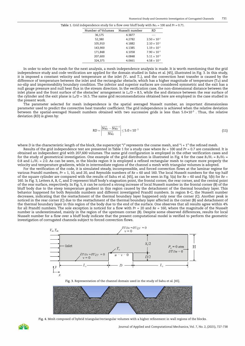
independence study and code verification are applied for the domain studied in Sahu et al. [45], illustrated in Fig. 3. In this study, it is imposed a constant velocity and temperature at the inlet (V∞ and T∞), and the convection heat transfer is caused by the difference of temperature between the inlet and the rectangular obstacle, which has a higher magnitude of temperature (TW) and no-slip and impermeability boundary condition. The inferior and superior surfaces are considered symmetric and the exit has a null gauge pressure and null heat flux in the stream direction. In the verification case, the non-dimensional distance between the inlet plane and the front surface of the obstacles’ arrangement is Lu/D = 8.5, while the and distance between the rear surface of the cylinder and the exit plane is Ld/D = 16.5. The same grid recommendations obtained here are employed in the case studied in the present work.
The parameter selected for mesh independence is the spatial averaged Nusselt number, an important dimensionless parameter used to predict the convective heat transfer coefficient. The grid independence is achieved when the relative deviation between the spatial-averaged Nusselt numbers obtained with two successive grids is less than 5.0⨯10-3 . Thus, the relative deviation (RD) is given by:
i iD D
iD
Nu NuRD
Nu
+
−−= ≤ ×
1
35.0 10 (11)
where D is the characteristic length of the block, the superscript “i” represents the coarse mesh, and “i + 1” the refined mesh.
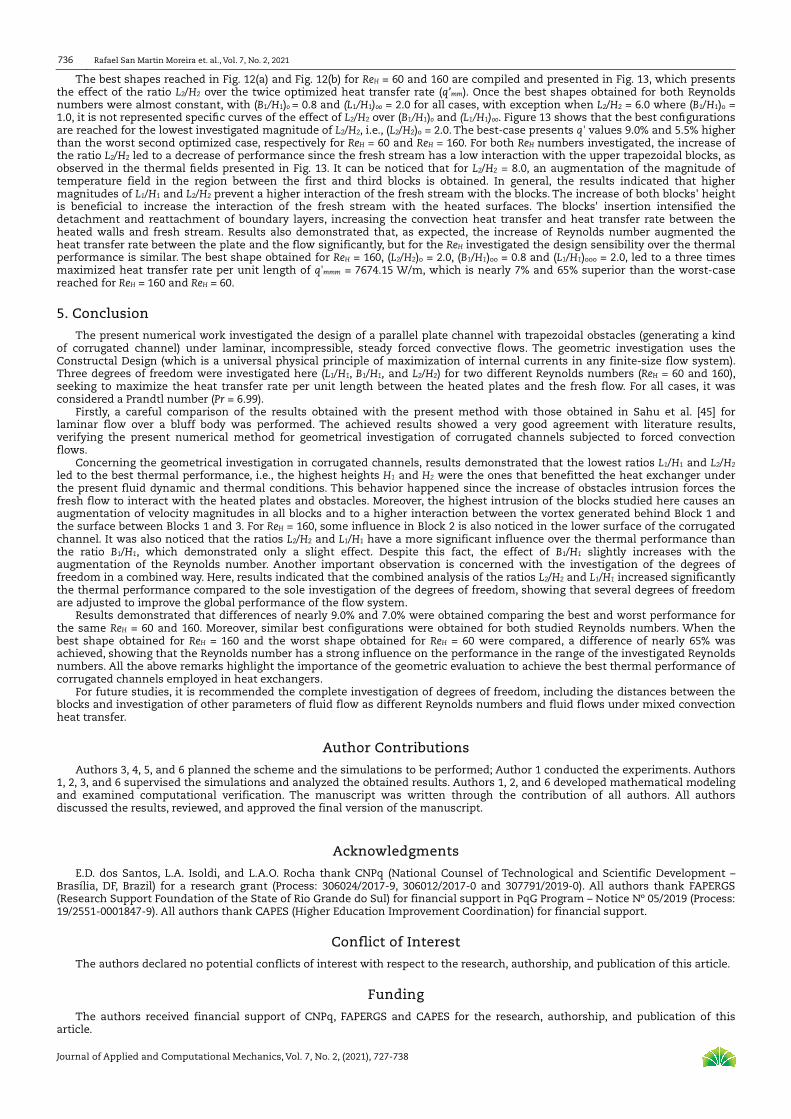
Results of the grid independence test are presented in Table 1 for a study case where Re = 100 and Pr = 0.7 are considered. It is obtained an independent grid with 207,600 volumes. The same grid configuration is employed in the other verification cases and for the study of geometrical investigation. One example of the grid distribution is illustrated in Fig. 4 for the case B1/H1 = B2/H2 = 0.8 and L1/H1 = 2.0. As can be seen, in the blocks region it is employed a refined rectangular mesh to capture more properly the velocity and temperature gradients, while in intermediate regions of the channel a mesh with triangular volumes is adopted.
For the verification of the code, it is simulated steady, incompressible, and forced convection flows at the laminar regime for various Prandtl numbers, Pr = 1, 10, and 20, and Reynolds numbers of Re = 60 and 160. The local Nusselt numbers for the top half of the square cylinder are compared with the results of Sahu et al. [45], as can be seen in Fig. 5(a) for Re = 60 and Fig. 5(b) for Re = 160. In Fig. 3, Letters A, B, C, and D represent bluff body's stagnation point, the frontal corner, the rear corner, and the central point of the rear surface, respectively. In Fig. 5, it can be noticed a strong increase of local Nusselt number in the frontal corner (B) of the bluff body due to the steep temperature gradient in this region caused by the detachment of the thermal boundary layer. This behavior happened for both Reynolds numbers and different investigated Prandtl numbers. In region B-C, the Nusselt number decreases, indicating that the reattachment of the thermal boundary layer happened only near the corner (C). Another peak is noticed in the rear corner (C) due to the reattachment of the thermal boundary layer affected in the corner (B) and detachment of the thermal boundary layer in this region of the body due to the end of the surface. One observes that all results agree within 4% for all Prandtl numbers. The sole exception is noticed for a flow with Pr = 20 and Re = 160, where the magnitude of the Nusselt number is underestimated, mainly in the region of the upstream corner (B). Despite some observed differences, results for local Nusselt number for a flow over a bluff body indicate that the present computational model is verified to perform the geometric investigation of corrugated channels subject to forced convection flows.
Fig. 3. Representation of the channel domain used in the study of Sahu et al. [45].
Fig. 4. Mesh composed of hybrid triangular/rectangular volumes with a higher refinement in wall regions of the blocks.

Rafael San Martin Moreira et. al., Vol. 7, No. 2, 2021
Journal of Applied and Computational Mechanics, Vol. 7, No. 2, (2021), 727-738
732
Fig. 5. Local Nusselt number (Nu) obtained from the present code and that presented in Sahu et al. [45] for flow with various Prandtl numbers, Pr = 1, 10 and 20, and a fixed Reynolds number: (a) ReD = 60, (b) ReD = 160.
Fig. 6. Effect of the ratio L1/H1 over heat transfer rate for different ratios of B1/H1 for ReH = 60 and Pr = 6.99.
4. Results and Discussion
Figure 6 shows the effect of the ratio L1/H1 on the heat transfer rate per unit length (q’) for three different values of B1/H1, and keeping fixed the ratios L2/H2 = 2.0 and B2/H2 = 0.8 for ReH = 60. As a general trend, it can be noticed that a decrease in the heat transfer rate as the ratio L1/H1 increases. Moreover, the optimal geometric configuration, i.e., the one that generates the greatest thermal performance, is the lowest investigated case (L1/H1)o = 2.0. This behavior happened because, for lower magnitudes of the ratio L1/H1, the trapezoidal form of the channel has a higher intrusion into spanwise direction of the channel, leading to an augmentation of momentum around the first trapezoidal obstacle and increasing the heat exchange area. It is worth mentioning that this condition is valid for the present fluid dynamic and thermal conditions once the momentum is imposed at the channel inlet. As performed in Feijó et al. [9, 46], other studies have demonstrated that other configurations can be achieved when a pressure drop is imposed on the channel. Results indicated that the highest difference between the best case, reached for B1/H1 = 0.8 and (L1/H1)o = 2.0, and the worst case, reached for B1/H1 = 0.8 and L1/H1 = 8.0, presented in Fig. 6, is nearly 1.7%. Moreover, in the region of lower performance, the curves with different magnitudes of B1/H1 crossed each other, indicating no dominance of one ratio of B1/H1 that conducts to the best performance for all magnitudes of L1/H1. Results also demonstrated that variation of the ratio B1/H1 in the range 0.8 ≤ B1/H1 ≤ 1.2 does not lead to important changes in the heat transfer rate per unit length (q’), i.e., the thermal performance showed a higher sensibility regarding the ratio L1/H1 than the ratio B1/H1.
Figures 7 and 8 show the velocity and thermal fields reached for three different geometric configurations predicted in Fig. 6 when ReH = 60 and Pr = 6.99. More precisely, Fig. 7(a) – (c) and Fig. 8(a) – (c) show the configurations: (L1/H1)o = 2.0, L1/H1 = 4.0 and L1/H1 = 8.0, respectively. Figure 7 illustrates the increase of the magnitude of velocity field near Block 1 with the decrease of the ratio L1/H1, i.e., with the increase of the block's intrusion in the spanwise direction of fluid flow. Once it is imposed a constant velocity at the channel inlet, the higher intrusion of the block in the channel causes an augmentation of momentum to conserve the mass in the domain. Moreover, the momentum is intensified over all blocks when the highest intrusion happened in Block 1. It is also observed an intensification of the detachment of fluid dynamic boundary layer behind Block 1. Concerning the influence of fluid dynamic behavior in the thermal fields, Fig. 8 shows that the detachment and reattachment behind Block 1 are intensified for the lowest magnitude of L1/H1, which can justify the augmentation of heat transfer between the heated surfaces of the channel and the fresh stream. In the downstream blocks (Block 2 and 3) it is not observed significant differences in the thermal boundary layers. Once changes of thermal boundary layers are restricted between Blocks 1 and 3, as well as, an augmentation of momentum in the region among the blocks is slight, this cause only slight differences of heat transfer rate found among the results, which is not superior to 2.0 % for the studied cases in Fig. 6.

Numerical Study and Geometric Investigation of Corrugated Channels
Journal of Applied and Computational Mechanics, Vol. 7, No. 2, (2021), 727-738
733
Fig. 7. Velocity fields obtained for three different geometric configurations when B1/H1 = 0.8 and ReH = 60: (a) (L1/H1)o = 2.0, (b) L1/H1 = 4.0, (c) L1/H1 = 8.0.
Fig. 8. Thermal behavior obtained for three different geometric configurations when B1/H1 = 0.8 and ReH = 60: (a) (L1/H1)o = 2.0, (b) L1/H1 = 4.0, (c) L1/H1 = 8.0.
Figure 9 shows the effect of the ratio L1/H1 over the heat transfer rate per unit length (q’) for the same conditions presented in
Fig. 6, but with a different Reynolds number: ReH = 160. The same trend showed in Fig. 6 can be seen in Fig. 9, i.e., the increase of the ratio L1/H1 led to a decrease of q’. Due to the increase of Reynolds number, the magnitudes of heat transfer rate per unit length are higher than that achieved for ReH = 60 (Fig. 6), which is expected. For instance, comparing both Figs. 6 and 9, it is observed an increase of 55% on the magnitude of q’ for the optimal ratio (L1/H1)o = 2.0 when B1/H1 = 0.8. Despite this increase, the effect of L1/H1 over q’ is similar for both ReH. Moreover, the once optimized ratio (L1/H1)o is obtained for the lowest investigated magnitude, i.e., (L1/H1)o = 2.0. It is also noticed that differences of q’ between the best ratio (L1/H1)o and the worst configuration does not exceed 2.0% for both Reynolds numbers, but it is not an unimportant effect, since, in compact heat exchangers, any gain in energy transfer is valuable. Results also indicated that the curves of q’ as a function of L1/H1 crossed each other when L1/H1 ≥ 4.0. Differences found between different ratios of B1/H1 were more significant for ReH = 160 than for ReH = 60, but the sensibility of this ratio over q’ regarding this ratio is still peripheral compared to the ratio L1/H1. Despite this fact, results indicate that this ratio can have a higher effect on the increase of Reynolds number, which should be investigated in future works.
Figures 10 and 11 show the velocity and thermal fields predicted for three different geometric configurations obtained in Fig. 9 for ReH = 160. More precisely, Fig. 10(a) – (c) and Fig. 11(a) – (c) show the configurations: (L1/H1)o = 2.0, L1/H1 = 4.0, L1/H1 = 8.0 when B1/H1 = 0.8. With the augmentation of Reynolds number, it can be seen a more intense magnitude of velocity fields, along with all domains compared to the case with ReH = 60, which is expected. In Fig. 10(a), it can be seen that the highest intrusion of Block 1 in the spanwise direction of the channel intensifies the detachment of velocity boundary layer and the reattachment happened in the downstream block (Block 3), while for configurations of Figs. 10(b) and 10(c), this effect is more smoothed. Concerning the thermal fields, Fig. 11 shows that the highest intrusion of Block 1 in the channel intensifies the mixture of energy behind it. The temperature mixture caused by vortex behind Block 1 seen in Fig. 11(a) is not observed in Figs. 11(b) and 11(c), where thermal boundary layers were smoothed. The velocity and temperature fields near Block 2 are similar for the three different configurations. However, the increase of Reynolds number from ReH = 60 to 160 intensified the differences of the vortex generated behind Block 2, which is indicative that the increase of the Reynolds number can affect the influence of configuration of Block 1 over the fluid dynamic and thermal behavior in the region of Block 2.

Rafael San Martin Moreira et. al., Vol. 7, No. 2, 2021
Journal of Applied and Computational Mechanics, Vol. 7, No. 2, (2021), 727-738
734
Fig. 9. Effect of the ratio L1/H1 over heat transfer rate for different ratios of B1/H1 for ReH = 160 and Pr = 6.99.
Fig. 10. Velocity fields obtained for three different geometric configurations when B1/H1 = 0.8 and ReH = 160: (a) (L1/H1)o = 2.0, (b) L1/H1 = 4.0, (c) L1/H1 = 8.0.
Fig. 11. Thermal behavior obtained for three different geometric configurations when B1/H1 = 0.8 and ReH = 160: (a) (L1/H1)o = 2.0, (b) L1/H1 = 4.0,
(c) L1/H1 = 8.0.

Numerical Study and Geometric Investigation of Corrugated Channels
Journal of Applied and Computational Mechanics, Vol. 7, No. 2, (2021), 727-738
735
The optimal shapes reached in Fig. 6, and Fig. 9 are compiled and reproduced in Fig. 12(a) and 12(b). More precisely, the effect of the ratio B1/H1 over the once maximized heat transfer rate (q’m) is presented for ReH = 60 and 160, given by Fig. 12(a) and 12(b), respectively. It is worth mentioning that the compilation of the results of Fig. 6 and Fig. 9 leads to the curve L2/H2 = 2.0 in Fig. 12(a) and Fig. 12(b). For the achievement of the other curves (L2/H2 = 4.0, 6.0, and 8.0), the same process performed in Fig. 6 and Fig. 9 is repeated for other magnitudes of L2/H2. It can be seen that all curves show similar behavior for all L2/H2 ratios, i.e., the increase of ratio B1/H1 led to a slight decrease of q’m. One notable exception is obtained for the ratio L2/H2 = 6.0, where the best ratio of B1/H1 was reached for B1/H1 = 1.0 and not for B1/H1 = 0.8 as predicted for other ratios of L2/H2. In general, it is also noticed that the combined investigation of the ratios L1/H1 and L2/H2 led to an augmentation of the thermal performance in comparison with the situation where just one degree of freedom is evaluated. For instance, the best and worst performance difference reached for ReH = 60, B1/H1 = 0.8, and B2/H2 = 0.8 is nearly 80 W/m, see Fig. 6, while the highest difference obtained in Fig. 12(a) increases to 350 W/m. The best-case presents magnitudes of q' 8.6% and 4.7% higher than the worst once optimized case, respectively in Fig. 12(a) and Fig. 12(b). Therefore, results indicated that the combined investigation of degrees of freedom is important for improving the thermal performance among the once optimized cases. Results of Fig. 12 reinforced that the effect of the degrees of freedom L2/H2 and L1/H1 over thermal performance is more significant than that noticed for the ratio B1/H1, for the present fluid dynamic and thermal conditions.
(a)
(b)
Fig. 12. Effect of ratio B1/H1 over heat transfer rate per unit length once maximized (q’m): (a) ReH = 60, (b) ReH = 160.
Fig. 13. Effect of ratio L2/H2 over heat transfer rate twice-maximized (q’mm) for two different ReH.
Rafael San Martin Moreira et. al., Vol. 7, No. 2, 2021
Journal of Applied and Computational Mechanics, Vol. 7, No. 2, (2021), 727-738
736
The best shapes reached in Fig. 12(a) and Fig. 12(b) for ReH = 60 and 160 are compiled and presented in Fig. 13, which presents the effect of the ratio L2/H2 over the twice optimized heat transfer rate (q’mm). Once the best shapes obtained for both Reynolds numbers were almost constant, with (B1/H1)o = 0.8 and (L1/H1)oo = 2.0 for all cases, with exception when L2/H2 = 6.0 where (B1/H1)o = 1.0, it is not represented specific curves of the effect of L2/H2 over (B1/H1)o and (L1/H1)oo. Figure 13 shows that the best configurations are reached for the lowest investigated magnitude of L2/H2, i.e., (L2/H2)o = 2.0. The best-case presents q' values 9.0% and 5.5% higher than the worst second optimized case, respectively for ReH = 60 and ReH = 160. For both ReH numbers investigated, the increase of the ratio L2/H2 led to a decrease of performance since the fresh stream has a low interaction with the upper trapezoidal blocks, as observed in the thermal fields presented in Fig. 13. It can be noticed that for L2/H2 = 8.0, an augmentation of the magnitude of temperature field in the region between the first and third blocks is obtained. In general, the results indicated that higher magnitudes of L1/H1 and L2/H2 prevent a higher interaction of the fresh stream with the blocks. The increase of both blocks' height is beneficial to increase the interaction of the fresh stream with the heated surfaces. The blocks' insertion intensified the detachment and reattachment of boundary layers, increasing the convection heat transfer and heat transfer rate between the heated walls and fresh stream. Results also demonstrated that, as expected, the increase of Reynolds number augmented the heat transfer rate between the plate and the flow significantly, but for the ReH investigated the design sensibility over the thermal performance is similar. The best shape obtained for ReH = 160, (L2/H2)o = 2.0, (B1/H1)oo = 0.8 and (L1/H1)ooo = 2.0, led to a three times maximized heat transfer rate per unit length of q'mmm = 7674.15 W/m, which is nearly 7% and 65% superior than the worst-case reached for ReH = 160 and ReH = 60.
5. Conclusion
The present numerical work investigated the design of a parallel plate channel with trapezoidal obstacles (generating a kind of corrugated channel) under laminar, incompressible, steady forced convective flows. The geometric investigation uses the Constructal Design (which is a universal physical principle of maximization of internal currents in any finite-size flow system). Three degrees of freedom were investigated here (L1/H1, B1/H1, and L2/H2) for two different Reynolds numbers (ReH = 60 and 160), seeking to maximize the heat transfer rate per unit length between the heated plates and the fresh flow. For all cases, it was considered a Prandtl number (Pr = 6.99).
Firstly, a careful comparison of the results obtained with the present method with those obtained in Sahu et al. [45] for laminar flow over a bluff body was performed. The achieved results showed a very good agreement with literature results, verifying the present numerical method for geometrical investigation of corrugated channels subjected to forced convection flows.
Concerning the geometrical investigation in corrugated channels, results demonstrated that the lowest ratios L1/H1 and L2/H2 led to the best thermal performance, i.e., the highest heights H1 and H2 were the ones that benefitted the heat exchanger under the present fluid dynamic and thermal conditions. This behavior happened since the increase of obstacles intrusion forces the fresh flow to interact with the heated plates and obstacles. Moreover, the highest intrusion of the blocks studied here causes an augmentation of velocity magnitudes in all blocks and to a higher interaction between the vortex generated behind Block 1 and the surface between Blocks 1 and 3. For ReH = 160, some influence in Block 2 is also noticed in the lower surface of the corrugated channel. It was also noticed that the ratios L2/H2 and L1/H1 have a more significant influence over the thermal performance than the ratio B1/H1, which demonstrated only a slight effect. Despite this fact, the effect of B1/H1 slightly increases with the augmentation of the Reynolds number. Another important observation is concerned with the investigation of the degrees of freedom in a combined way. Here, results indicated that the combined analysis of the ratios L2/H2 and L1/H1 increased significantly the thermal performance compared to the sole investigation of the degrees of freedom, showing that several degrees of freedom are adjusted to improve the global performance of the flow system.
Results demonstrated that differences of nearly 9.0% and 7.0% were obtained comparing the best and worst performance for the same ReH = 60 and 160. Moreover, similar best configurations were obtained for both studied Reynolds numbers. When the best shape obtained for ReH = 160 and the worst shape obtained for ReH = 60 were compared, a difference of nearly 65% was achieved, showing that the Reynolds number has a strong influence on the performance in the range of the investigated Reynolds numbers. All the above remarks highlight the importance of the geometric evaluation to achieve the best thermal performance of corrugated channels employed in heat exchangers.
For future studies, it is recommended the complete investigation of degrees of freedom, including the distances between the blocks and investigation of other parameters of fluid flow as different Reynolds numbers and fluid flows under mixed convection heat transfer.
Author Contributions
Authors 3, 4, 5, and 6 planned the scheme and the simulations to be performed; Author 1 conducted the experiments. Authors 1, 2, 3, and 6 supervised the simulations and analyzed the obtained results. Authors 1, 2, and 6 developed mathematical modeling and examined computational verification. The manuscript was written through the contribution of all authors. All authors discussed the results, reviewed, and approved the final version of the manuscript.
Acknowledgments
E.D. dos Santos, L.A. Isoldi, and L.A.O. Rocha thank CNPq (National Counsel of Technological and Scientific Development – Brasília, DF, Brazil) for a research grant (Process: 306024/2017-9, 306012/2017-0 and 307791/2019-0). All authors thank FAPERGS (Research Support Foundation of the State of Rio Grande do Sul) for financial support in PqG Program – Notice Nº 05/2019 (Process: 19/2551-0001847-9). All authors thank CAPES (Higher Education Improvement Coordination) for financial support.
Conflict of Interest
The authors declared no potential conflicts of interest with respect to the research, authorship, and publication of this article.
Funding
The authors received financial support of CNPq, FAPERGS and CAPES for the research, authorship, and publication of this article.

Numerical Study and Geometric Investigation of Corrugated Channels
Journal of Applied and Computational Mechanics, Vol. 7, No. 2, (2021), 727-738
737
Nomenclature
A A1 A2 B1 B2
Cp g H H1
H2
L
L1 L2 L3
m
Channel area [m2] Upper obstacle area [m2] Lower obstacle area [m2] Smaller upstream block base [m] Length of the smaller base of the downstream block [m] specific heat [J∙kg-1∙K-1] acceleration of gravity the y direction [m∙s-2] Height of the channel [m] Upstream fin height [m] Height of the downstream fin [m] Channel length [m] Length of the largest upstream block base [m] Length of the largest base of the downstream block [m] Distance between the centers of the blocks [m] Once maximized
mm mmm o oo ooo Pr q’ ReH T∞ u∞
Twice maximized Thrice maximized Once optimized Twice optimized Thrice optimized Prandtl number [-] Heat transfer rate per unit length [W∙m−1] Reynolds number [-] Free-stream temperature [K] Velocity of the fluid at the entrance to the channel [m∙s-1] Thermal difusivity [m2.s] Thermal expansion coefficient [K-1] Kinematic velocity [m2.s] Fluid dynamic viscosity [kg∙m-1∙s-1] Density [kg∙m-3]
References
[1] Bejan, A., Convection Heat Transfer, John Wiley & Sons, New York, 2013. [2] Ismael, M.A., Forced convection in partially compliant channel with two alternated baffles, International Journal of Heat and Mass Transfer, 142, 2019, 118455. [3] Iwaniszyn, M., Jodłowski, P.J., Sindera, K., Gancarczyk, A., Korpyś, M., Jędrzejczyk, R.J., Kołodziej, A., Entrance effects on forced convective heat transfer in laminar flow through short hexagonal channels: Experimental and CFD study, Chemical Engineering Journal, 405, 2021, 126635. [4] Kakaç, S., Liu, H., Heat Exchangers: Selection, Rating and Thermal Design, CRC Press, Boca Raton, 2002. [5] Bobič, M., Gjerek, B., Golobič, I., Bajsić, I., Dynamic behavior of a plate heat exchanger: influence of temperature disturbances and flow configurations, International Journal of Heat and Mass Transfer, 163, 2020, 120439. [6] You, J., Feng, H., Chen, L., Xie, Z., Xia, S., Constructal design and experimental validation of a non-uniform heat generating body with rectangular cross-section and parallel circular cooling channels, International Journal of Heat and Mass Transfer, 148, 2020, 119028. [7] Samee, A.D.M., Afzal, A., Ramis, M.K., Abdul Razak, R.K., Optimal spacing in heat generating parallel plate channel: a conjugate approach, International Journal of Thermal Sciences, 136, 2019, 267-277. [8] Fomicheva, M., Müller, W.H., Vilchevskaya, E.N., Bessonov, N., Funnel flow of a Navier-Stokes-fluid with potential applications to micropolar media, Facta Universitatis Series: Mechanical Engineering, 17(2), 2019, 255-267. [9] Feijó, B.C., Lorenzini, G., Isoldi, L.A., Rocha, L.A.O., Goulart, J.N.V., Dos Santos, E.D., Constructal design of forced convective flows in channels with two alternated rectangular heated bodies, International Journal of Heat and Mass Transfer, 125, 2018, 710-721. [10] Adhikari, R.C., Wood, D.H., Pahlevani, M., An experimental and numerical study of forced convection heat transfer from rectangular fins at low Reynolds numbers, International Journal of Heat and Mass Transfer, 163, 2020, 120418. [11] Nishimura, T., Arakawa, S., Murakami, S., Kawamura, Y., Oscillatory viscous flow in symmetric wavy-walled channels, Chemical Engineering Science, 44, 1989, 2137-2148. [12] Vasudeviah, M., Balamurugan, K., On forced convective heat transfer for a stokes flow in a wavy channel, International Communications in Heat and Mass Transfer, 28, 2001, 289-297. [13] Kim, S.M., Mudawar, I., Universal approach to predicting heat transfer, International Journal of Heat and Mass Transfer, 56, 2013, 238 – 250. [14] Jing, D., Song, J., Sui, Y., Hydraulic and thermal performances of laminar flow in fractal treelike branching microchannel network with wall velocity slip, Fractals, 28, 2020, 2050022. [15] Lyu, Z., Pourfattah, F., Arani, A.A.A., Asadi, A., Foong, L.K., On the thermal performance of a fractal microchannel subjected to water and kerosene carbon nanotube nanofluid, Scientific Reports, 10, 2020, 7243. [16] Durgam, S., Venkateshan, S.P., Sundararajan, T., Experimental and numerical investigations on optimal distribution of heat source array under natural and forced convection in a horizontal channel, International Journal of Thermal Sciences, 115, 2017, 125 – 138. [17] Sheikholeslami, M., Farshad, S.A., Shafee, A., Babazadeh, H., Performance of solar collector with turbulator involving nanomaterial turbulent regime, Renewable Energy, 163, 2021, 1222–1237. [18] Sheikholeslami, M., Farshad, S.A., Nanoparticle transportation inside a tube with quad-channel tapes involving solar radiation, Powder Technology, 378(A), 2021, 145 – 159. [19] Sheikholeslami, M., Jafaryar, M., Said, Z., Alsabery, A.I., Babazadeh, H., Shafee, A., Modification for helical turbulator to augment heat transfer behavior of nanomaterial via numerical approach, Applied Thermal Engineering, 182, 2021, 115935. [20] Sheremet, M.A., Oztop, H.F., Pop, I., MHD natural convection in an inclined wavy cavity with corner heater filled with a nonofluid, Journal of Magnetism and Magnetic Materials, 416, 2016, 37 – 47. [21] Sheikholeslami, M., Oztop, H.F., MHD free convection of nanofluid in a cavity with sinusoidal walls by using CVFEM, Chinese Journal of Physics, 55(6), 2017, 2291–2304. [22] Afrand, M., Pordanjani, A.H., Aghakhani, S., Oztop, H.F., Abu-Hamdeh, N., Free convection and entropy generation of a nanofluid in a tilted triangular cavity exposed to a magnetic field with sinusoidal wall temperature distribution considering radiation effects, International Communications in Heat and Mass Transfer, 112, 2020, 104507. [23] Bejan, A., Shape and Structure, from Engineering to Nature, Cambridge Univ. Press, Cambridge, 2000. [24] Bejan, A., Lorente, S., Design with Constructal Theory, Wiley, New Jersey, 2008. [25] Bejan, A., Zane, J.P., Design in Nature, Doubleday, New York, 2012. [26] Bejan, A., The Physics of Life: The Evolution of Everything, St. Martins, New York, 2016. [27] Bejan, A., Freedom and Evolution: Hierarchy in Nature, Society and Science. Springer Nature, Switzerland, 2020. [28] Bejan, A., Evolution in thermodynamics, Applied Physics Review, 4, 2017, 011305. [29] Hajmohammadi, M.R., Optimal design of tree-shaped inverted fins, International Journal of Heat and Mass Transfer, 116, 2018, 1352–1360. [30] Estrada, E.S.D., Barreto, E.X., Isoldi, L.A., dos Santos, E.D., Lorente, S., Rocha, L.A.O., Constructal design of tree shaped cavities inserted into a cylindrical body with heat generation, International Journal of Thermal Sciences, 152, 2020, 106342-106342-10. [31] Mosa, M., Labat, M., Lorente, S., Constructal design of flow channels for radiant cooling panels, International Journal of Thermal Sciences, 145, 2019, 106052. [32] Teixeira, F.B., Lorenzini, G., Errera, M.R., Rocha, L.A.O., Isoldi, L.A., Dos Santos, E.D., Constructal Design of triangular arrangements of square bluff bodies under forced convective turbulent flows, International Journal of Heat and Mass Transfer, 126, 2018, 521 – 535. [33] Vieira, R.S., Petry, A.P., Rocha, L.A.O., Isoldi, E.D., Dos Santos, E.D., Numerical evaluation of a solar chimney geometry for different ground temperatures by means of constructal design, Renewable Energy, 109, 2017, 222–234. [34] Martins, J.C., Goulart, M.M., Gomes, M.N., Souza, J.A., Rocha, L.A.O., Isoldi, L.A., Dos Santos, E.D., Geometric Evaluation of the Main Operational Principle of an Overtopping Wave Energy Converter by Means of Constructal Design, Renewable Energy, 118, 2018, 727–741. [35] Wu, Z., Feng, H., Chen, L., Xie, Z., Cai, C., Pumping power minimization of an evaporator in ocean thermal energy conversion system based on Constructal theory, Energy, 181, 2019, 974 – 984.

Rafael San Martin Moreira et. al., Vol. 7, No. 2, 2021
Journal of Applied and Computational Mechanics, Vol. 7, No. 2, (2021), 727-738
738
[36] Seibt, F.M., de Camargo, F.V., Dos Santos E.D., Gomes, M.N., Rocha, L.A.O., Isoldi, L.A., Fragassa C., Numerical Evaluation on the Efficiency of the Submerged Horizontal Plate Type Wave Energy Converter, FME Transactions, 47(2), 2019, 543-551. [37] Magalhães, G.M.C., Fragassa, C., Lemos, R.L., Isoldi, L.A., Amico, S.C., Rocha, L.A.O., Souza, J.A., Dos Santos, E.D., Numerical Analysis of the Influence of Empty Channels Design on Performance of Resin Flow in a Porous Plate, Applied Sciences, 10(11), 2020, 4054. [38] Mardanpour, P., Izadpanahi, E., Powell, S., Rastkar, S., Bejan, A., Inflected wings in flight: uniform flow of stresses makes strong and light wings for stable flight, Journal of Theoretical Biology, 508, 2021, 110452. [39] Lima, J.P.S., Cunha, M.L., Dos Santos, E.D., Rocha, L.A.O., Real, M.V., Isoldi, L.A., Constructal Design for the ultimate buckling stress improvement of stiffened plates submitted to uniaxial compressive load, Engineering Structures, 203, 2020, 109883. [40] Adewumi, O.O., Bello-Ochende, T., Meyer, J.P., Constructal Design of Combined Microchannel and Micro Pin Fns for Electronic Cooling, International Journal of Heat and Mass Transfer, 66, 2013, 315–323. [41] Teixeira, F.B., Altnetter, M.V., Lorenzini, G., Rodriguez, B.D. do A., Rocha, L.A.O., Isoldi, L.A., Dos Santos, E.D., Geometrical evaluation of a channel with alternated mounted blocks under mixed convection laminar flows using Constructal Design, Journal of Engineering Thermophysics, 29, 2020, 92–113. [42] Versteeg, H.K., Malalasekera, W., An Introduction to Computational Fluid Dynamics—The Finite Volume Method, Longman, London, 2007. [43] Patankar, S.V., Numerical Heat Transfer and Fluid Flow, McGraw-Hill, New York, 1980. [44] ANSYS, 14.0, FLUENT User’s Guide, ANSYS Inc., 2011. [45] Sahu, A.K., Chhabra, R.P., Eswaran, V., Effects of Reynolds and Prandtl numbers on heat transfer from a square cylinder in the unsteady flow regime, International Journal of Heat and Mass Transfer, 52, 2009, 839 – 850. [46] Feijó, B.C., Pereira, M.S., Teixeira, F.B., Isoldi, L.A., Rocha, L.A.O., Goulart, J.N.V., Dos Santos, E.D., Constructal Design Applied to a Channel with Triangular Fins Submitted to Forced Convection, Defect and Diffusion Forum, 372, 2017, 152-162.
ORCID iD
Rafael San Martin Moreira https://orcid.org/0000-0002-9336-6903 Cícero Coelho de Escobar https://orcid.org/0000-0002-6248-9222 Liércio André Isoldi https://orcid.org/0000-0002-9337-3169 Rodrigo Rocha Davesac https://orcid.org/0000-0001-5051-5529 Luiz Alberto Oliveira Rocha https://orcid.org/0000-0003-2409-3152 Elizaldo Domingues dos Santos https://orcid.org/0000-0003-4566-2350
© 2020 by the authors. Licensee SCU, Ahvaz, Iran. This article is an open access article distributed under the terms and conditions of the Creative Commons Attribution-NonCommercial 4.0 International (CC BY-NC 4.0 license) (http://creativecommons.org/licenses/by-nc/4.0/).
How to cite this article: Rafael San Martin Moreira et al., Numerical Study and Geometric Investigation of Corrugated Channels Subjected to Forced Convective Flows, J. Appl. Comput. Mech., 7(2), 2021, 727–738. https://doi.org/10.22055/JACM.2020.35345.2634