Fiber-Optic Technology Tutorial
22
Web ProForum Tutorials http://www.iec.org Copyright © The International Engineering Consortium 1/22 Fiber-Optic Technology Tutorial Definition Fiber-optic communications is based on the principle that light in a glass medium can carry information over longer distances than electrical signals can carry in a copper or coaxial medium. The glass purity of today's fiber, combined with improved system electronics, enables fiber to transmit digitized light signals well beyond 100 km (60 miles) without amplification. With few transmission losses, low interference, and high bandwidth potential, optical fiber is an almost ideal transmission medium. Overview The advantages provided by optical fiber systems are the result of a continuous stream of product innovations and process improvements. As the requirements and emerging opportunities of optical fiber systems are better understood, fiber is improved to address them. This tutorial provides an extensive overview of the history, construction, operation, and benefits of optical fiber, with particular emphasis on outside vapor deposition (OVD) process. Topics 1. From Theory to Practical Application: A Quick History 2. How Fiber Works 3. OVD Process 4. OVD Benefits 5. Fiber Geometry: A Key Factor in Splicing and System Performance 6. How to Choose Optical Fiber Self-Test Correct Answers Acronym Guide
-
Upload
khangminh22 -
Category
Documents
-
view
0 -
download
0
Transcript of Fiber-Optic Technology Tutorial

Web ProForum Tutorialshttp://www.iec.org
Copyright ©The International Engineering Consortium
1/22
Fiber-Optic Technology Tutorial
DefinitionFiber-optic communications is based on the principle that light in a glass mediumcan carry information over longer distances than electrical signals can carry in acopper or coaxial medium. The glass purity of today's fiber, combined withimproved system electronics, enables fiber to transmit digitized light signals wellbeyond 100 km (60 miles) without amplification. With few transmission losses,low interference, and high bandwidth potential, optical fiber is an almost idealtransmission medium.
OverviewThe advantages provided by optical fiber systems are the result of a continuousstream of product innovations and process improvements. As the requirementsand emerging opportunities of optical fiber systems are better understood, fiberis improved to address them. This tutorial provides an extensive overview of thehistory, construction, operation, and benefits of optical fiber, with particularemphasis on outside vapor deposition (OVD) process.
Topics1. From Theory to Practical Application: A Quick History
2. How Fiber Works
3. OVD Process
4. OVD Benefits
5. Fiber Geometry: A Key Factor in Splicing and System Performance
6. How to Choose Optical Fiber
Self-Test
Correct Answers
Acronym Guide
Web ProForum Tutorialshttp://www.iec.org
Copyright ©The International Engineering Consortium
2/22
1. From Theory to Practical Application: AQuick HistoryAn important principle in physics became the theoretical foundation for opticalfiber communications: light in a glass medium can carry more information overlonger distances than electrical signals can carry in a copper or coaxial medium.
The first challenge undertaken by scientists was to develop a glass so pure thatone percent of the light would be retained at the end of one kilometer (km), theexisting unrepeatered transmission distance for copper-based telephone systems.In terms of attenuation, this one percent of light retention translated to twentydecibels per kilometer (dB per km) glass material.
Glass researchers all over the world worked on the challenge in the 1960s, but thebreakthrough came in 1970, when Corning scientists Drs. Robert Maurer, DonaldKeck, and Peter Schultz created a fiber with a measured attenuation of less than20 dB per km. It was the purest glass ever made.
The three scientists' work is recognized as the discovery that led the way to thecommercialization of optical fiber technology. Since then, the technology hasadvanced tremendously in terms of performance, quality, consistency, andapplications.
Working closely with customers has made it possible for scientists to understandwhat modifications are required, to improve the product accordingly throughdesign and manufacturing, and to develop industry-wide standards for fiber.
The commitment to optical fiber technology has spanned more than twenty yearsand continues today with the endeavor to determine how fiber is currently usedand how it can meet the challenges of future applications. As a result of researchand development efforts to improve fiber, a high level of glass purity has beenachieved. Today, fiber's optical performance is approaching the theoretical limitsof silica-based glass materials. This purity, combined with improved systemelectronics, enables fiber to transmit digitized light signals well beyond 100 km(more than 60 miles) without amplification. When compared with earlyattenuation levels of 20 dB per km, today's achievable levels of 0.35 dB per km at1310 nanometers (nm) and 0.25 dB per km at 1550 nm, testify to the incredibledrive for improvement.
2. How Fiber WorksThe operation of an optical fiber is based on the principle of total internalreflection. Light reflects (bounces back) or refracts (alters its course whilepenetrating a different medium), depending on the angle at which it strikes a
Web ProForum Tutorialshttp://www.iec.org
Copyright ©The International Engineering Consortium
3/22
surface. This occurs because different interfaces between materials refract light indifferent ways.
One way of thinking about this concept is to envision a person looking at a lake.By looking down at a steep angle, the person will see fish, rocks, vegetation, orwhatever is below the surface of the water, assuming that the water is relativelyclear and calm. However, by casting a glance farther out, thus making the angleof sight less steep, the individual is likely to see a reflection of trees or otherobjects on an opposite shore. Because air and water have different indices ofrefraction, the angle at which a person looks into or across the water influencesthe image seen.
This principle is at the heart of how optical fiber works. Lightwaves are guidedthrough the core of the optical fiber in much the same way that radio frequency(RF) signals are guided through coaxial cable. The lightwaves are guided to theother end of the fiber by being reflected within the core. Controlling the angle atwhich the light waves are transmitted makes it possible to control how efficientlythey reach their destination. The composition of the cladding glass relative to thecore glass determines the fiber's ability to refract light. The difference in theindex of refraction of the core and the cladding causes most of the transmittedlight to bounce off the cladding glass and stay within the core. In this way, thefiber core acts as a waveguide for the transmitted light.
The Design of Fiber
Core and Cladding
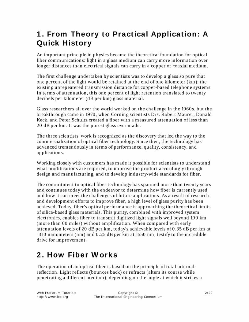
An optical fiber consists of two different types of highly pure, solid glass to formthe core and cladding. A protective acrylate coating (see Figure 1) then surroundsthe cladding. In some cases, the protective coating may be a dual layer.
Figure 1. Core and Cladding
Web ProForum Tutorialshttp://www.iec.org
Copyright ©The International Engineering Consortium
4/22
A protective coating is applied to the glass fiber as the final step in themanufacturing process. This coating protects the glass from dust and scratchesthat can affect fiber strength. This protective coating can be comprised of twolayers: a soft inner layer that cushions the fiber and allows the coating to bestripped from the glass mechanically and a harder outer layer that protects thefiber during handling, particularly the cabling and installation/terminationprocesses.
Single-Mode and Multimode Fibers
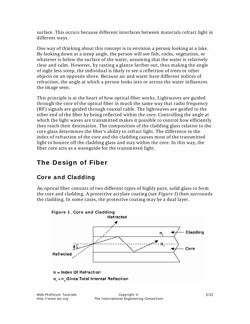
There are two general categories of optical fiber: single mode and multimode (seeFigure 2).
Figure 2. Single-Mode and Multimode Fibers
Multimode fiber was the first type of fiber to be commercialized. It has a muchlarger core than single-mode fiber, allowing hundreds of rays or modes of light topropagate through the fiber simultaneously. Additionally, the larger corediameter of multimode fiber facilitates the use of lower-cost optical transmittersand connectors.
Single-mode fiber, on the other hand, has a much smaller core that allows onlyone mode of light at a time to propagate through the core. While it might appearthat multimode fibers have higher capacity, in fact the opposite is true. Single-mode fibers are designed to maintain the integrity of each optical signal overlonger distances, allowing more information to be transmitted.
Its tremendous information-carrying capacity and low intrinsic loss have madesingle-mode fiber the ideal transmission medium for a multitude of applications.Multimode fiber is used primarily in systems with short transmission distances(under 2 km), such as premises communications and private data networks.
Optical Fiber Sizes
The international standard outer cladding diameter of most single-mode opticalfibers is 125 microns (µm) for the glass and 245 µm for the coating. This standardis important because it ensures compatibility among connectors, splices, andtools used throughout the industry.
Web ProForum Tutorialshttp://www.iec.org
Copyright ©The International Engineering Consortium
5/22
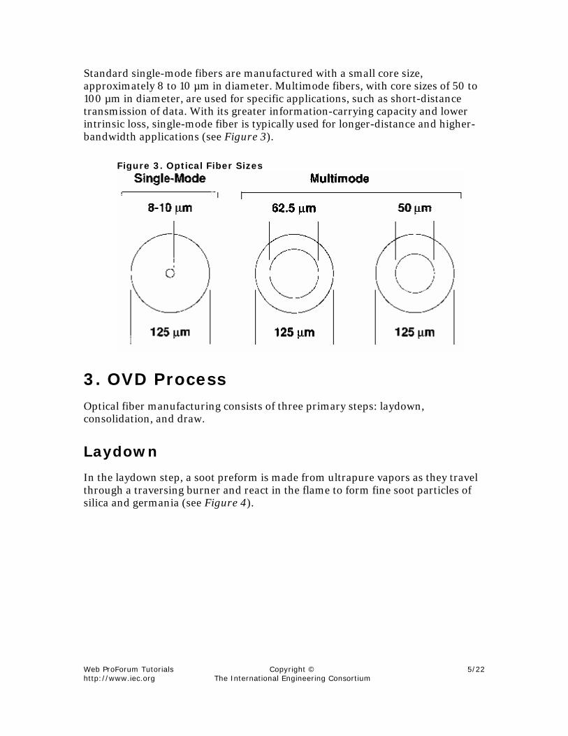
Standard single-mode fibers are manufactured with a small core size,approximately 8 to 10 µm in diameter. Multimode fibers, with core sizes of 50 to100 µm in diameter, are used for specific applications, such as short-distancetransmission of data. With its greater information-carrying capacity and lowerintrinsic loss, single-mode fiber is typically used for longer-distance and higher-bandwidth applications (see Figure 3).
Figure 3. Optical Fiber Sizes
3. OVD ProcessOptical fiber manufacturing consists of three primary steps: laydown,consolidation, and draw.
Laydown
In the laydown step, a soot preform is made from ultrapure vapors as they travelthrough a traversing burner and react in the flame to form fine soot particles ofsilica and germania (see Figure 4).

Web ProForum Tutorialshttp://www.iec.org
Copyright ©The International Engineering Consortium
6/22
Figure 4. OVD Laydown Process
The OVD process is distinguished by the method of depositing the soot. Theseparticles are deposited on the surface of a rotating target rod. The core material isdeposited first, followed by the pure silica cladding. As both core and claddingraw materials are vapor-deposited, the entire preform is extremely pure.
Consolidation
When deposition is complete, the target rod is removed from the center of theporous preform, and the preform is placed into a consolidation furnace. Duringthe consolidation process, the water vapor is removed from the preform. Thishigh-temperature consolidation step sinters the preform into a solid, dense, andtransparent glass. The hole left by the target rod disappears completely; there isno hole in the finished fiber.
The Draw
The finished glass preform is placed in a draw tower and drawn into a continuousstrand of glass fiber (see Figure 5).
Web ProForum Tutorialshttp://www.iec.org
Copyright ©The International Engineering Consortium
7/22
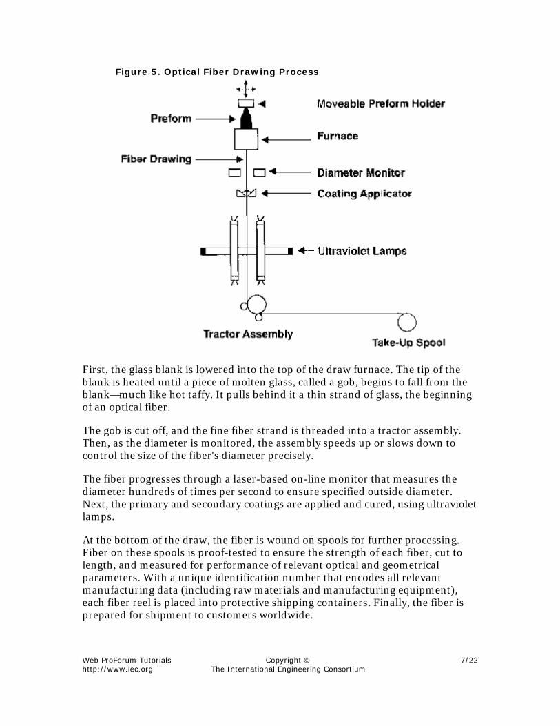
Figure 5. Optical Fiber Drawing Process
First, the glass blank is lowered into the top of the draw furnace. The tip of theblank is heated until a piece of molten glass, called a gob, begins to fall from theblank—much like hot taffy. It pulls behind it a thin strand of glass, the beginningof an optical fiber.
The gob is cut off, and the fine fiber strand is threaded into a tractor assembly.Then, as the diameter is monitored, the assembly speeds up or slows down tocontrol the size of the fiber's diameter precisely.
The fiber progresses through a laser-based on-line monitor that measures thediameter hundreds of times per second to ensure specified outside diameter.Next, the primary and secondary coatings are applied and cured, using ultravioletlamps.
At the bottom of the draw, the fiber is wound on spools for further processing.Fiber on these spools is proof-tested to ensure the strength of each fiber, cut tolength, and measured for performance of relevant optical and geometricalparameters. With a unique identification number that encodes all relevantmanufacturing data (including raw materials and manufacturing equipment),each fiber reel is placed into protective shipping containers. Finally, the fiber isprepared for shipment to customers worldwide.

Web ProForum Tutorialshttp://www.iec.org
Copyright ©The International Engineering Consortium
8/22
4. OVD BenefitsThe benefits of fiber produced by the patented OVD process include enhancedreliability, lower attenuation, and solid geometrical and optical consistency.
Matched-Clad Fiber Consistency
Fibers are made of a core and cladding glass, each with slightly differentcompositions. The manufacturing process determines the relationship betweenthose two glasses. The OVD process produces matched-clad fiber, the single-mode fiber design that allows for the most consistent fiber (see Figure 6).
Figure 6. Matched-Clad Fiber Design
The OVD process produces well-controlled fiber profiles and geometry, both ofwhich lead to a more consistent fiber. Fiber-to-fiber consistency is especiallyimportant when fibers from different manufacturing periods are united to forman optical system.
Depressed-Clad Fiber Profile
The inside vapor deposition (IVD) or modified chemical vapor deposition(MCVD) process produces what is called depressed-clad fiber because of theshape of its refractive index profile.
Figure 7. Depressed-Clad Fiber Design
Depressed-clad fibers are made with two different cladding glasses that form aninner and an outer cladding region. The inner cladding region adjacent to thefiber core has an index of refraction that is lower than that of pure silica, while

Web ProForum Tutorialshttp://www.iec.org
Copyright ©The International Engineering Consortium
9/22
the outer cladding has an index equal to that of pure silica. This depressed regionis typically a design requirement as a result of using the IVD process.
Questions of Strength
One common misconception about optical fiber is that it must be fragile becauseit is made of glass. In fact, research, theoretical analysis, and practical experienceprove that the opposite is true. While traditional bulk glass is brittle, theultrapure glass of optical fibers exhibits both high tensile strength and extremedurability.
How strong is fiber? Figures like 600 or 800 thousand pounds per square inchare often cited, far more than copper's capability of 100 pounds per square inch.That figure refers to the ultimate tensile-breaking strength of fiber producedtoday. This is fiber's real, rather than theoretical, strength, which is 2 millionpounds per square inch.
ABCs of Fiber Strength
The actual strength of optical fiber is determined by the depth of inherentmicroscopic flaws on its surface. These microscopic flaws exist in any fiber. As ina length of chain, the weakest link (or, in fiber's case, the deepest flaw)determines the ultimate strength of the entire length of fiber.
The OVD process offers a significant benefit in the area of fiber strength. BecauseOVD does not start with a bulk-glass or externally manufactured rube, everymillimeter of the fiber is made from the ultrapure vapor-deposition process andcontains fewer surface flaws.
Many fiber manufacturers tensile-load, or proof-test, fiber after production. Thisprocess eliminates the largest flaws, thereby ensuring a strength level tospecification.
Life Expectancy
Fiber is designed and manufactured to provide a lifetime service of twenty yearsor more, provided it is cabled and installed according to recommendedprocedures. Life expectancy can be extrapolated from many tests. These testresults, along with theoretical analysis, support the prediction of long service life.Environmental issues are also important to consider when evaluating a fiber'smechanical performance.

Web ProForum Tutorialshttp://www.iec.org
Copyright ©The International Engineering Consortium
10/22
Bending Parameters
Optical fiber cable is easy to install because of its light weight, small size, andflexibility. Nevertheless, some people new to fiber express concern over theprecautions required to avoid too-tight bends, which can cause loss of light orpremature fiber breakage.
Experience and testing show that bare fiber can be safely looped with benddiameters as small as two inches, the recognized industry standard for minimum-bend diameter. Splice trays and other fiber-handling equipment, such as racks,are designed to prevent fiber-installation errors.
5. Fiber Geometry: A Key Factor inSplicing and System PerformanceAs greater volumes of fiber in higher-fiber-count cables are installed, systemengineers are becoming increasingly conscious of the impact of splicing on theirsystems. Splice yields and losses have a profound impact on the quality of systemperformance and the cost of installation.
Glass geometry, the physical dimensions of an optical fiber, has been shown to bea primary contributor to splice loss and splice yield. Early on, one companyrecognized the benefits provided by tightly controlled fiber geometry and hassteadily invested in continuous improvement in this area. Its tightly controlledmanufacturing process helps engineers reduce systems costs and yet remainwithin the industry's low maximum splice-loss requirement.
Fiber that exhibits tightly controlled geometry tolerances will not only be easierand faster to splice but will also reduce the need for testing by ensuringpredictable, high-quality splice performance. This is particularly true when fibersare spliced by passive, mechanical, or fusion techniques for both single fibers andfiber ribbons. In addition, tight geometry tolerances lead to the additional benefitof flexibility in equipment choice.
The benefits of tighter geometry tolerances can be significant. In today's fiber-intensive architectures, it is estimated that splicing and testing can account formore than 30 percent of the total labor costs of system installation.
Fiber Geometry Parameters
The three fiber geometry parameters that have the greatest impact on splicingperformance are the following:

Web ProForum Tutorialshttp://www.iec.org
Copyright ©The International Engineering Consortium
11/22
• cladding diameter the outside diameter of the cladding glassregion
• core/clad concentricity (or core-to-cladding offset) how wellthe core is centered in the cladding glass region
• fiber curl the amount of curvature over a fixed length of fiber
These parameters are determined and controlled during the fiber-manufacturingprocess. As fiber is cut and spliced according to needs dictated by each individualsystem, it is important to be able to count on consistent geometry along the entirelength of the fiber and not to rely solely on measurements made only at the end ofthe fiber.
Cladding Diameter
Cladding diameter tolerances control the outer diameter of the fiber, with tightertolerances ensuring that fibers are almost exactly the same size. During splicing,inconsistent cladding diameters can cause cores to be misaligned where the fibersjoin, leading to higher losses.
Cladding diameter tolerances are controlled by the drawing rate. Somemanufacturers are able to control the tolerance of the cladding to a level of 125.0±1.0 µm. Once the cladding diameter tolerance is tightened to this level,core/clad concentricity becomes the single largest geometry contributor to spliceloss.
Core/Clad Concentricity
Tighter core/clad concentricity tolerances help ensure that the fiber core iscentered in relation to the cladding. This reduces the chance of ending up withcores that do not match up precisely when two fibers are spliced together. A corethat is precisely centered in the fiber yields lower-loss splices more often.
Core/clad concentricity is determined during the first stages of themanufacturing process, when the fiber design and resulting characteristics arecreated. During these laydown and consolidation processes, the dopant chemicalsthat make up the fiber must be deposited with precise control and symmetry tomaintain consistent core/clad concentricity performance throughout the entirelength of fiber.
Fiber Curl
Fiber curl is the inherent curvature along a specific length of optical fiber that isexhibited to some degree by all fibers. It is a result of thermal stresses that occur

Web ProForum Tutorialshttp://www.iec.org
Copyright ©The International Engineering Consortium
12/22
during the manufacturing process. Therefore, these factors must be rigorouslymonitored and controlled during fiber manufacture. Tighter fiber-curl tolerancesreduce the possibility that fiber cores will be misaligned during splicing, therebyimpacting splice loss.
Typical mass fusion splicers use fixed v-grooves for fiber alignment, where theeffect of fiber curl is most noticeable.
Figure 8. Cladding Diameter, Core/Clad Concentricity, and FiberCurl
6. How to Choose Optical Fiber
Single-Mode Fiber Performance Characteristics
The key optical performance parameters for single-mode fibers are attenuation,dispersion, and mode-field diameter.
Optical fiber performance parameters can vary significantly among fibers fromdifferent manufacturers, in ways that can affect your system's performance. It isimportant to understand how to specify the fiber that best meets systemrequirements.
Attenuation
Attenuation is the reduction of signal strength or light power over the length ofthe light-carrying medium. Fiber attenuation is measured in decibels perkilometer (dB/km).

Web ProForum Tutorialshttp://www.iec.org
Copyright ©The International Engineering Consortium
13/22
Optical fiber offers superior performance over other transmission media becauseit combines high bandwidth with low attenuation. This allows signals to betransmitted over longer distances while using fewer regenerators (amplifiers),reducing cost, and improving reliability.
Dispersion
Dispersion is the smearing or broadening of an optical signal that results fromthe many discrete wavelength components traveling at different rates (see Figure9). In digital transmission, dispersion limits the maximum data rate orinformation-carrying capacity of a single-mode fiber link. In analog transmission,dispersion can cause a waveform to become significantly distorted and can resultin unacceptable levels of composite second-order distortion (CSO).
Figure 9. Signal Dispersion
Dispersion vs. Wavelength
Fiber dispersion varies with wavelength and is controlled by fiber design (seeFigure 10). The wavelength at which dispersion equals zero is called the zero-dispersion wavelength. This is the wavelength at which fiber has its maximuminformation-carrying capacity. For standard single-mode fibers, this is in theregion of 1310 nm.

Web ProForum Tutorialshttp://www.iec.org
Copyright ©The International Engineering Consortium
14/22
Figure 10. Dispersion and Wavelength
Dispersion is expressed as the time increase in signal width (in picoseconds) perunit divided by the source spectral width (in nm) per unit times the length offiber (in km).
Chromatic dispersion consists of two kinds of dispersion. Material dispersionrefers to the pulse spreading caused by the specific composition of the glass.Waveguide dispersion is the pulse spreading that occurs as the light travels inboth the core and the inner cladding glasses. The two types can be balanced toproduce a wavelength of zero dispersion at 1310 nm.
Dispersion-Shifted Fiber
Optical fibers also can be manufactured to have the zero dispersion wavelength inthe 1550 nm region, which coincides with fiber's lowest attenuation point.Dispersion-shifted fiber can allow for greater transmission capacity over longerdistances than would be possible with standard single-mode fiber.
Transmission in the 1550 nm Window
Optical fibers also can be manufactured to have the zero dispersion wavelength inthe 1550 nm region, which is also the point where silica-based fibers haveinherently minimal attenuation. These fibers are referred to as nonzerodispersion-shifted fiber (NZDSF). This fiber is used primarily in applications thatrequire both long-distance and high-capacity transmission rates.
For applications such as the interconnection of headends, delivery ofprogramming to remote node sites, high-speed communication networks, andregional and metropolitan rings (used primarily for competitive access

Web ProForum Tutorialshttp://www.iec.org
Copyright ©The International Engineering Consortium
15/22
applications), NZDSF fiber can improve system reliability, increase capacity, andlower system costs (see Figure 11).
Figure 11. Wavelength and Dispersion
Mode-Field Diameter
Mode-field diameter (MFD) describes the size of the light-carrying portion of thefiber. This region includes the fiber core as well as a portion of the surroundingcladding glass. MFD is an important parameter for determining a fiber'sresistance to bend-induced loss and can affect splice loss as well. MFD, ratherthan core diameter, is the functional parameter that determines opticalperformance when a fiber is coupled to a light source, connectorized, spliced, orbent. It is a function of wavelength, core diameter, and the refractive-indexdifference between the core and the cladding. These last two are fiber design andmanufacturing parameters.
Cutoff Wavelength
Cutoff wavelength is the wavelength above which a single-mode fiber supportsonly one mode or ray of light. An optical fiber that is single-moded at a particularwavelength has two or more modes at wavelengths shorter than the cutoffwavelength.
The effective cutoff wavelength of a fiber is dependent on the length of fiber andits deployment. The longer the fiber, the shorter the effective cutoff wavelength.Or, the smaller the bend radius of a loop of the fiber is, the shorter the effectivecutoff wavelength will be.
Environmental Performance
While cable design and construction play a key role in environmentalperformance, optimum system performance requires the user to specify fiber thatwill operate without undue loss from microbending.

Web ProForum Tutorialshttp://www.iec.org
Copyright ©The International Engineering Consortium
16/22
Microbends are small-scale perturbations along the fiber axis, the amplitude ofwhich are on the order of microns. These distortions can cause light to leak out ofa fiber. Microbending may be induced at very cold temperatures because theglass has a different coefficient of thermal expansion from the coating andcabling materials. At low temperatures, the coating and cable become more rigidand contract more than the glass. Consequently, enough load may be exerted onthe glass to cause microbends. Coating, fiber ribbon, and cabling materials areselected by manufacturers to minimize loss due to microbending.
Specification Examples of Uncabled Fiber
To ensure that a cabled fiber provides the best performance for a specificapplication, it is important to work with an optical fiber–cable supplier to specifythe fiber parameters just reviewed as well as the geometric characteristics thatprovide the consistency necessary for acceptable splicing and connectorizing.
Splicers and Connectors
As optical fiber moves closer to the customer, where cable lengths are shorter andcables have higher fiber counts, the need for joining fibers becomes greater.Splicing and connectorizing play a critical role both in the cost of installation andin system performance.
The object of splicing and connectorizing is to match, precisely, the core of oneoptical fiber with that of another in order to produce a smooth channel throughwhich light signals can continue without alteration or interruption.
There are two ways that fibers are joined:
• splices, which form permanent connections between fibers in thesystem
• connectors, which provide remateable connections, typically attermination points
Fusion Splicing
Fusion splicing provides a fast, reliable, low-loss, fiber-to-fiber connection bycreating a homogenous joint between the two fiber ends. The fibers are melted orfused together by heating the fiber ends, typically using an electric arc. Fusionsplices provide the highest-quality joint with the lowest loss (in the range of 0.04dB to 0.10 dB) and are practically nonreflective.

Web ProForum Tutorialshttp://www.iec.org
Copyright ©The International Engineering Consortium
17/22
Mechanical Splicing
Mechanical splicing is an alternative method of making a permanent connectionbetween fibers. In the past, the disadvantages of mechanical splicing have beenslightly higher losses, less-reliable performance, and a cost associated with eachsplice. However, advances in the technology have significantly improved itsperformance. System operators typically use mechanical splicing for emergencyrestoration because it is fast, inexpensive, and easy.
Connectors
Connectors are used in applications where flexibility is required in routing anoptical signal from lasers to receivers, wherever reconfiguration is necessary, andin terminating cables. These remateable connections simplify systemreconfigurations to meet changing customer requirements.
Self-Test1. A physics principle that became the theoretical foundation of optical fiber
communications holds that ___________ in a __________ medium cancarry more information over longer distances.
a. light; coaxial
b. electrical signals; glass
c. light; glass
d. electrical signals; copper
2. Single-mode fiber was the first type of fiber to be commercialized.
a. true
b. false
3. What are the three primary steps in the optical fiber manufacturing process?
a. laydown, compilation, and draw
b. assembly, consolidation, and pull
c. laydown, consolidation, and draw
d. assembly, compilation, and pull

Web ProForum Tutorialshttp://www.iec.org
Copyright ©The International Engineering Consortium
18/22
4. Which of the following is not a characteristic of the fiber produced by the OVDprocess?
a. less attenuation
b. infinite flexibility
c. exceptional strength
d. fewer flaws
5. Fiber curl is exhibited by all fibers.
a. true
b. false
6. Attenuation is which of the following?
a. the inherent curvature along a specific length of optical fiber
b. the wavelength above which a single-mode fiber supports only onemode or ray of light
c. the reduction of signal strength over the length of the light-carryingmedium
d. smearing an optical signal that results from the many discretewavelength components traveling at different rates
7. Controlling the ____________ at which light waves are transmitted makesit possible to control how efficiently they reach their destination.
a. speed
b. angle
c. time
d. rate
8. Dispersion is which of the following?
a. the inherent curvature along a specific length of optical fiber
b. the wavelength above which a single-mode fiber supports only onemode or ray of light

Web ProForum Tutorialshttp://www.iec.org
Copyright ©The International Engineering Consortium
19/22
c. the reduction of signal strength over the length of the light-carryingmedium
d. smearing an optical signal that results from the many discretewavelength components traveling at different rates
9. The longer the fiber is, the shorter the effective cutoff wavelength will be.
a. true
b. false
10. Mechanical splicing is the predominant choice of operators for joining fibers.
a. true
b. false
Correct Answers1. A physics principle that became the theoretical foundation of optical fiber
communications holds that ___________ in a __________ medium cancarry more information over longer distances.
a. light; coaxial
b. electrical signals; glass
c. light; glass
d. electrical signals; copper
See Topic 1.
2. Single-mode fiber was the first type of fiber to be commercialized.
a. true
b. false
See Topic 2.
3. What are the three primary steps in the optical fiber manufacturing process?
a. laydown, compilation, and draw
b. assembly, consolidation, and pull

Web ProForum Tutorialshttp://www.iec.org
Copyright ©The International Engineering Consortium
20/22
c. laydown, consolidation, and draw
d. assembly, compilation, and pull
See Topic 2.
4. Which of the following is not a characteristic of the fiber produced by the OVDprocess?
a. less attenuation
b. infinite flexibility
c. exceptional strength
d. fewer flaws
See Topic 4.
5. Fiber curl is exhibited by all fibers.
a. true
b. false
See Topic 5.
6. Attenuation is which of the following?
a. the inherent curvature along a specific length of optical fiber
b. the wavelength above which a single-mode fiber supports only onemode or ray of light
c. the reduction of signal strength over the length of the light-carrying medium
d. smearing an optical signal that results from the many discretewavelength components traveling at different rates
See Topic 6.
7. Controlling the ____________ at which light waves are transmitted makesit possible to control how efficiently they reach their destination.
a. speed
b. angle

Web ProForum Tutorialshttp://www.iec.org
Copyright ©The International Engineering Consortium
21/22
c. time
d. rate
See Topic 2.
8. Dispersion is which of the following?
a. the inherent curvature along a specific length of optical fiber
b. the wavelength above which a single-mode fiber supports only onemode or ray of light
c. the reduction of signal strength over the length of the light-carryingmedium
d. smearing an optical signal that results from the manydiscrete wavelength components traveling at different rates
See Topic 6.
9. The longer the fiber is, the shorter the effective cutoff wavelength will be.
a. true
b. false
See Topic 6.
10. Mechanical splicing is the predominant choice of operators for joining fibers.
a. true
b. false
See Topic 6.
Acronym GuideCNRcarrier-to-noise ratio
CSOcomposite second-order distortion
IVDinside vapor deposition

Web ProForum Tutorialshttp://www.iec.org
Copyright ©The International Engineering Consortium
22/22
MCVDmodified chemical vapor deposition
MFDmode-field diameter
NZDSFnonzero dispersion-shifted fiber
OVDoutside vapor deposition
RFradio frequency