On-Board Fiber-Optic Network Architectures for Radar and Avionics Signal Distribution
18
Mohammad F. Alam, Mohammed Atiquzzaman, and Bradley B. Duncan University of Dayton, Dayton, Ohio Hung Nguyen and Richard Kunath Glenn Research Center, Cleveland, Ohio On-Board Fiber-Optic Network Architectures for Radar and Avionics Signal Distribution NASA/TM—2000-209776 March 2000
-
Upload
independent -
Category
Documents
-
view
1 -
download
0
Transcript of On-Board Fiber-Optic Network Architectures for Radar and Avionics Signal Distribution

Mohammad F. Alam, Mohammed Atiquzzaman, and Bradley B. DuncanUniversity of Dayton, Dayton, Ohio
Hung Nguyen and Richard KunathGlenn Research Center, Cleveland, Ohio
On-Board Fiber-Optic Network Architecturesfor Radar and Avionics Signal Distribution
NASA/TM—2000-209776
March 2000

The NASA STI Program Office . . . in Profile
Since its founding, NASA has been dedicated tothe advancement of aeronautics and spacescience. The NASA Scientific and TechnicalInformation (STI) Program Office plays a key partin helping NASA maintain this important role.
The NASA STI Program Office is operated byLangley Research Center, the Lead Center forNASA’s scientific and technical information. TheNASA STI Program Office provides access to theNASA STI Database, the largest collection ofaeronautical and space science STI in the world.The Program Office is also NASA’s institutionalmechanism for disseminating the results of itsresearch and development activities. These resultsare published by NASA in the NASA STI ReportSeries, which includes the following report types:
• TECHNICAL PUBLICATION. Reports ofcompleted research or a major significantphase of research that present the results ofNASA programs and include extensive dataor theoretical analysis. Includes compilationsof significant scientific and technical data andinformation deemed to be of continuingreference value. NASA’s counterpart of peer-reviewed formal professional papers buthas less stringent limitations on manuscriptlength and extent of graphic presentations.
• TECHNICAL MEMORANDUM. Scientificand technical findings that are preliminary orof specialized interest, e.g., quick releasereports, working papers, and bibliographiesthat contain minimal annotation. Does notcontain extensive analysis.
• CONTRACTOR REPORT. Scientific andtechnical findings by NASA-sponsoredcontractors and grantees.
• CONFERENCE PUBLICATION. Collectedpapers from scientific and technicalconferences, symposia, seminars, or othermeetings sponsored or cosponsored byNASA.
• SPECIAL PUBLICATION. Scientific,technical, or historical information fromNASA programs, projects, and missions,often concerned with subjects havingsubstantial public interest.
• TECHNICAL TRANSLATION. English-language translations of foreign scientificand technical material pertinent to NASA’smission.
Specialized services that complement the STIProgram Office’s diverse offerings includecreating custom thesauri, building customizeddata bases, organizing and publishing researchresults . . . even providing videos.
For more information about the NASA STIProgram Office, see the following:
• Access the NASA STI Program Home Pageat http://www.sti.nasa.gov
• E-mail your question via the Internet [email protected]
• Fax your question to the NASA AccessHelp Desk at (301) 621-0134
• Telephone the NASA Access Help Desk at(301) 621-0390
• Write to: NASA Access Help Desk NASA Center for AeroSpace Information 7121 Standard Drive Hanover, MD 21076

NASA/TM—2000-209776
March 2000
National Aeronautics andSpace Administration
Glenn Research Center
Prepared for theInternational Radar Conferencesponsored by the Institute of Electrical and Electronics EngineersAlexandria, Virginia, May 7–12, 2000
Mohammad F. Alam, Mohammed Atiquzzaman, and Bradley B. DuncanUniversity of Dayton, Dayton, Ohio
Hung Nguyen and Richard KunathGlenn Research Center, Cleveland, Ohio
On-Board Fiber-Optic Network Architecturesfor Radar and Avionics Signal Distribution

Available from
NASA Center for Aerospace Information7121 Standard DriveHanover, MD 21076Price Code: A03
National Technical Information Service5285 Port Royal RoadSpringfield, VA 22100
Price Code: A03
This report is a preprint of a paper intended for presentation at a conference. Becauseof changes that may be made before formal publication, this preprint is made
available with the understanding that it will not be cited or reproduced without thepermission of the author.
NASA/TM—2000-209776 1
On-board Fiber-optic Network Architectures for Radar and Avionics Signal Distribution
Mohammad F. Alam, Mohammed Atiquzzaman, Bradley B. DuncanDepartment of Electrical and Computer Engineering
University of DaytonDayton, Ohio 45469
Hung Nguyen and Richard KunathNational Aeronautics and Space Administration
Glenn Research CenterCleveland, Ohio 44135
ABSTRACT
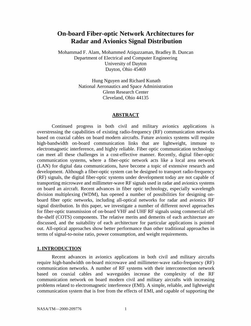
Continued progress in both civil and military avionics applications isoverstressing the capabilities of existing radio-frequency (RF) communication networksbased on coaxial cables on board modern aircrafts. Future avionics systems will requirehigh-bandwidth on-board communication links that are lightweight, immune toelectromagnetic interference, and highly reliable. Fiber optic communication technologycan meet all these challenges in a cost-effective manner. Recently, digital fiber-opticcommunication systems, where a fiber-optic network acts like a local area network(LAN) for digital data communications, have become a topic of extensive research anddevelopment. Although a fiber-optic system can be designed to transport radio-frequency(RF) signals, the digital fiber-optic systems under development today are not capable oftransporting microwave and millimeter-wave RF signals used in radar and avionics systemson board an aircraft. Recent advances in fiber optic technology, especially wavelengthdivision multiplexing (WDM), has opened a number of possibilities for designing on-board fiber optic networks, including all-optical networks for radar and avionics RFsignal distribution. In this paper, we investigate a number of different novel approachesfor fiber-optic transmission of on-board VHF and UHF RF signals using commercial off-the-shelf (COTS) components. The relative merits and demerits of each architecture arediscussed, and the suitability of each architecture for particular applications is pointedout. All-optical approaches show better performance than other traditional approaches interms of signal-to-noise ratio, power consumption, and weight requirements.
1. INTRODUCTION
Recent advances in avionics applications in both civil and military aircraftsrequire high-bandwidth on-board microwave and millimeter-wave radio-frequency (RF)communication networks. A number of RF systems with their interconnection networkbased on coaxial cables and waveguides increase the complexity of the RFcommunication network on board modern civil and military aircrafts with increasingproblems related to electromagnetic interference (EMI). A simple, reliable, and lightweightcommunication system that is free from the effects of EMI, and capable of supporting the

NASA/TM—2000-209776 2
broadband RF communications needs of the future on-board avionics systems can notimplemented by existing coaxial cable based systems easily. Fiber-optic communicationsystems can meet all the challenges of modern avionics applications in an efficient andcost-effective manner where a single fiber has the potential to replace dozens of RFcables [1]. In addition, a number of optical fibers can be bundled in a single fiber-opticcable, which has the potential to reduce the weight of the fiber-optic cable networksignificantly. In addition, fiber-optic components for airborne applications which arecapable of withstanding the adverse environmental conditions on-board an aircraft arealready under development [2-6].
Presently, two different optical wavelength regions are used for modern opticalcommunication in optical fiber. These wavelength regions are around 1.31 and1.55 micron (1310 and 1550 nm, respectively). For both of these wavelengths twomethods can be used for fiber-optic transmission: analog and digital. Analog signals arecontinuously varying signals where the exact waveform of the RF signal needs to bepreserved when transmitted over a fiber optic link. This requires the analog fiber-optictransmitter and the analog fiber-optic receiver to be extremely stable, linear, and to have alarge dynamic range. These stringent requirements increase the cost of analog fiber optictransmitters and receivers considerably. On the other hand, digital signals are composedof ones and zeros as in computers. The digital signal does not require preserving the exactwaveform of the transmitted signal as long as the transmitted signal is not distorted to theextent that ones and zeroes can not be distinguished from each other. For these reasons,digital fiber-optic communication equipment can perform well even when noise anddistortion of the optical signal is present.
Fiber-optic communication networks onboard aircrafts for digital datacommunication has recently become an active area of research and development [7-11].However, the systems under development today are digital fiber-optic communicationsystems which are capable of carrying digital data only, but are not capable oftransporting radar and avionics RF signals from one place to another on board an aircraft.Analog fiber-optic links can be employed to transport microwave and millimeter-waveRF signals from one place to another on board an aircraft. These analog fiber-optic linkstake as input an RF signal, transports it over fiber, and reproduces at the output an exactreplica of the RF waveform fed to it at the input end. The RF signal itself may bemodulated by a baseband signal by any of the analog or digital modulation techniques,but an analog fiber-optic link transmits the RF signal in the same manner irrespective ofthe method of modulation used for modulating the RF signal by the baseband signal.Figure 1 shows a typical RF signal (modulated by analog or digital modulationtechniques) being transported by an analog fiber-optic link.
An optical transmitter launches the optical signal into an optical fiber. At the otherend of the fiber, we need an optical receiver that converts the optical signal to RF again.Usually a single fiber can carry information in one direction only (simplex) which meansthat we usually require two fibers for bi-directional (duplex) communication. However,recent advances in wavelength division multiplexing make it possible to use the samefiber for duplex communication using different wavelengths.
In this paper, we will discuss a number of architectures for RF signal distributionwith traditional hybrid RF-optical as well as modern all-optical approaches usingcommercial off-the-shelf (COTS) components. The rest of the paper is organized as

NASA/TM—2000-209776 3
follows. In Section 2, we introduce the principles of some of the novel fiber-opticcommunication techniques based on recent advances in fiber optic systems. Section 3discusses some generalized fiber-optic distribution networks including all-opticalsolutions, whereas Section 4 describes fiber-optic architectures for multiple-sourcemultiple-destination networks. We conclude this paper in Section 5
A nalogmodulator
Digitalmodulator
Fiber-optictrans mitter
Fiber-opticrec eiv er
A nalogdemodulator
Digitaldemodulator
A nalogs ignal
Digitaldata
101010...
A nalogs ignal
Digital data101010...
A nalog f iber-optic link
f iberPow er
Combiner
Figure 1: An analog fiber-optic link transports RF signals where the RF signal may be modulated by ananalog or a digital modulation techniques.
2. TRADITIONAL AND MODERN FIBER-OPTIC SYSTEMSWe first show how a simple system can be implemented using both traditional
and modern all-optical approaches. Figure 2 shows such a simple system where an on-board VHF system communicates with a VHF antenna, and an on-board UHF systemcommunicates with a UHF antenna.
Figure 2: A simple fiber-optic communication system. The VHF antenna communicates with the VHFsystem, and the UHF antenna communicates with the UHF system.
NASA/TM—2000-209776 4
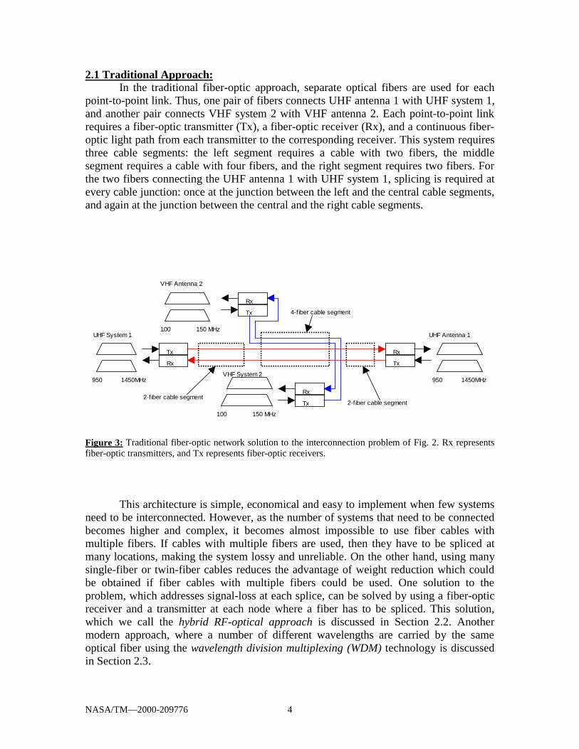
2.1 Traditional Approach:In the traditional fiber-optic approach, separate optical fibers are used for each
point-to-point link. Thus, one pair of fibers connects UHF antenna 1 with UHF system 1,and another pair connects VHF system 2 with VHF antenna 2. Each point-to-point linkrequires a fiber-optic transmitter (Tx), a fiber-optic receiver (Rx), and a continuous fiber-optic light path from each transmitter to the corresponding receiver. This system requiresthree cable segments: the left segment requires a cable with two fibers, the middlesegment requires a cable with four fibers, and the right segment requires two fibers. Forthe two fibers connecting the UHF antenna 1 with UHF system 1, splicing is required atevery cable junction: once at the junction between the left and the central cable segments,and again at the junction between the central and the right cable segments.
Tx
Rx
Tx
Rx
Rx
Tx
Tx
Rx
950 1450MHz 950 1450MHz
100 150 MHz
100 150 MHz
VHF System 2
VHF Antenna 2
UHF System 1 UHF Antenna 1
2-fiber cable segment2-f iber cable segment
4-f iber cable segment
Figure 3: Traditional fiber-optic network solution to the interconnection problem of Fig. 2. Rx representsfiber-optic transmitters, and Tx represents fiber-optic receivers.
This architecture is simple, economical and easy to implement when few systemsneed to be interconnected. However, as the number of systems that need to be connectedbecomes higher and complex, it becomes almost impossible to use fiber cables withmultiple fibers. If cables with multiple fibers are used, then they have to be spliced atmany locations, making the system lossy and unreliable. On the other hand, using manysingle-fiber or twin-fiber cables reduces the advantage of weight reduction which couldbe obtained if fiber cables with multiple fibers could be used. One solution to theproblem, which addresses signal-loss at each splice, can be solved by using a fiber-opticreceiver and a transmitter at each node where a fiber has to be spliced. This solution,which we call the hybrid RF-optical approach is discussed in Section 2.2. Anothermodern approach, where a number of different wavelengths are carried by the sameoptical fiber using the wavelength division multiplexing (WDM) technology is discussedin Section 2.3.
NASA/TM—2000-209776 5
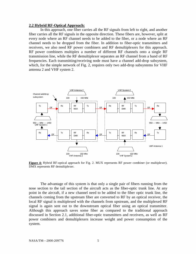
2.2 Hybrid RF-Optical Approach:In this approach, one fiber carries all the RF signals from left to right, and another
fiber carries all the RF signals in the opposite direction. These fibers are, however, split atevery node where an RF channel needs to be added to the fiber, or a node where an RFchannel needs to be dropped from the fiber. In addition to fiber-optic transmitters andreceivers, we also need RF power combiners and RF demultiplexers for this approach.RF power combiners multiplex a number of different RF channels onto a single RFtransmission line, while the RF demultiplexer separates an RF channel from a band of RFfrequencies. Each transmitting/receiving node must have a channel add-drop subsystem,which, for the simple network of Fig. 2, requires only two add-drop subsystems for VHFantenna 2 and VHF system 2.
RxTx RxTxRFDMX
RxTxRFMUX
Rx Tx RFDMX
Rx Tx RFMUX
Rx Tx
UHF System 1950 --- MHz --- 1450
100 150 MHz
VHF Antenna 2100 150 MHz
100 150 MHz
100 150 MHzVHF System 2
950 --- MHz -- 1450
UHF Antenna 1
OF
OF
OF
OF
OF
OF
Channel add/dropsubsystem
VHF Antenna 2 VHF System 2
Figure 4: Hybrid RF-optical approach for Fig. 2. MUX represents RF power combiner (or multiplexer).DMX represents RF demultiplexer.
The advantage of this system is that only a single pair of fibers running from thenose section to the tail section of the aircraft acts as the fiber-optic trunk line. At anypoint in the aircraft, if a new channel need to be added to the fiber optic trunk line, thechannels coming from the upstream fiber are converted to RF by an optical receiver, thelocal RF signal is multiplexed with the channels from upstream, and the multiplexed RFsignal is again sent out to the downstream optical fiber using an optical transmitter.Although this approach saves some fiber as compared to the traditional approachdiscussed in Section 2.1, additional fiber-optic transmitters and receivers, as well as RFpower combiners and demultiplexers increase weight and power consumption of thesystem.

NASA/TM—2000-209776 6
Figure 5: All-optical solution to the problem of Fig. 2 using wavelength division multiplexing
2.3 All-Optical Approach:The method of sending more than one wavelengths through an optical fiber is
called wavelength-division multiplexing (WDM), which is a new and evolvingtechnology. Using WDM technology, it is possible to share a single fiber for carrying twoor more optical channels at different optical wavelengths simultaneously. Thus, a singlefiber carries a number of optical wavelengths, and each of the wavelengths carry anumber of multiplexed RF channels. In this approach, we need optical power splitters,optical power combiners, and optical wavelength demultiplexers. Optical power splitterssplit the optical power received from an incoming optical fiber into two or more equal orunequal fractions, and each fraction is transmitted to a new outgoing fiber.
In order to implement the system in Fig. 2, we can choose the wavelength1330 nm for the UHF system, while the VHF system will communicate on 1280 nm.(Both a splitter and a combiner have the same physical construction. So, a singlecomponent can work either as a combiner or as a splitter depending on the way it isconnected). We still require two fibers, one for transmission in each direction. However,we do not need four fibers in the central segment as in Fig. 2. For the fiber carrying signalfrom left to right, optical signals from two transmitters, one from the UHF system 1 andthe other from the VHF antenna 2, are combined by an optical power combiner. One ofthe transmitters transmit at the wavelength 1280 nm, while the other transmitter operatesat the wavelength 1330 nm. The combiner at the VHF antenna 2 combines the twowavelengths and launches the combined power onto a single fiber, which runs up to thepoint where the VHF system 2 is located. At that point, a power splitter splits the totalpower into two equal halves. The receiver for the VHF system 2 at 1280 nm will receiveits channel from VHF antenna 2 via one of the ports of the splitter. The other port of thesplitter transmits half of the signal which is received by the UHF antenna 1. The receiverat UHF antenna 1 receives its channel from the UHF system 1 on 1330 nm. Both of thesereceivers (VHF system 2 and UHF antenna 1) should have the capability to choose theright wavelength from the two wavelengths (1280 and 1330 nm). The right wavelengthcan be easily separated by an optical wavelength demultiplexer at the receiver. For

NASA/TM—2000-209776 7
communication in the reverse direction, we need another fiber running in the oppositedirection, and two more combiners/splitters.
The advantage of this method is that it is an all-optical solution where an opticalsignal injected into the system by an optical transmitter remains in optical form until theoptical signal is received by the corresponding optical receiver. Thus, a complete light-path exists between an optical transmitter and an optical receiver for every wavelengththat is present in the system, and there is no optical-to-RF and RF-to-optical conversion(as in the solution of Section 2.2) which may degrade the signal-to-noise ratio of the RFsignal being carried by the optical signal. Also, the ability to carry many RF signals ondifferent wavelengths over the same fiber means savings in weight. In addition, the use ofwavelength multiplexers and demultiplexers, which are passive components requiring nopower supply, reduces the power consumption compared to hybrid RF-optical systems.
3. FIBER-OPTIC SIGNAL DISTRIBUTION SYSTEMSIn this section, we discuss the problem of designing a fiber-optic signal
distribution network which distributes an RF signal originating from a single source (e.g.,an antenna) and distributes it to a number of points on an aircraft. Figure 6 shows thedistribution system design problem in detail. Here, a single VHF antenna receives RFsignals which need to be distributed to a number of on-board systems (1, 2, 3 etc.). Wecan adopt either a hybrid RF-optical approach as in Section 2.2, or an all-optical approachas in Section 2.3. Both these approaches to implement the system in Fig. 6 are discussednext.
Figure 6: A fiber-optic signal distribution system.
3.1 Hybrid RF-Optical Approach:In this method we extend the idea of Section 2.2 to multiple nodes. There is only
one pair of fibers running from the nose to the tail of an aircraft. At each point (called anode) the incoming optical signal coming from the left side is converted to RF, the local

NASA/TM—2000-209776 8
RF channel is extracted, and a new optical signal is transmitted by a fiber-optictransmitter to the outgoing fiber-optic link. Figure 7 shows the implementation details ofthis approach, where each node is a receiving node. The details of each node aredescribed in Figure 8.
Tx Node 1 Node 2 Node 3
VHF Antenna(4 channels)
System 1( 4 channels)
System 2(4 channels)
System 3( 4 channels)
Other Systems
Figure 7: Schematic diagram of hybrid RF-optical solution of the problem in Fig. 6.
TxRxFromTx
ToRx
To Passenger
Figure 8: Detailed schematic of a receiving node in Fig. 7.
This solution is simple and requires only a single fiber running over the length ofthe aircraft. However, each node requires a fiber-optic transmitter as well as a receiver inthis approach.
3.2 All-Optical ApproachA fiber-optical splitter is a device which splits the optical power received from a
single fiber into a number of fractions and then transmits each fraction to a separate fiber.It is usually a passive device which is simple and light-weight in construction. Using oneor more levels of splitters, it is possible to generate a distribution tree from a singlesource of fiber-optic signal.
Figure 9 shows the all-optical solution to the signal distribution problem of Fig. 6.In this approach, we first convert the RF signal into an optical signal using a fiber-optictransmitter. Then it is split into eight by a one-to-eight optical splitter. Each of the splitoptical signals may go through repeaters (where the weak optical signal is first convertedto RF, and then re-transmitted by a fiber-optic transmitter, as in Fig. 10). Each of theseoptical signals is then again split into eight by another level of optical power splitters. Ifrepeaters are not used, then each receiver receives only 1/64 of the optical powertransmitted by the optical transmitter at the antenna.

NASA/TM—2000-209776 9
This system is highly advantageous because the optical signal is distributed by anall-optical network (except for repeaters, if needed) and the overall design of the systemis simple and easy to implement.
Rx Rx Rx Rx Rx RxRxRx Rx
Rp Rp Rp
Tx
VHF Antenna(4 channels)
Figure 9: Schematic diagram of all-optical solution to the problem of Fig. 6. Rp represents optionalrepeaters which may or may not be required depending on the signal strength at the final receivers.
Rx
Tx
Figure 10: Detailed schematic of a Repeater (Rp)
4. SYSTEMS WITH MULTIPLE TRANSMITTERS AND RECEIVERSFinally, we describe the design methodology for an on-board system where
multiple nodes are transmitting, and each of the systems on board the aircraft must becapable of receiving the transmission from any one of the transmitters.
Figure 11 shows a communications architecture with three antennas from whereoptical signals are transmitted, and these signals should be transported to any of the on-board systems (three shown in Fig. 11). As in the earlier sections, we can take either thehybrid RF-optical approach, or the all-optical approach.

NASA/TM—2000-209776 10
Figure 11: A fiber-optic communication network architecture with multiple transmitters and receivers.
4.1 Hybrid RF-Optical ApproachIn this approach, we use two fibers running in opposite directions throughout the
length of an aircraft. At the location of each (transmitting) antenna or (receiving) system,the optical signal is first converted to RF, and then either a new RF channel is added incase of a transmitting node, or the received signal is retransmitted in case of a receivingnode. Figure 12 shows the block diagram of such a multiple-transmitter multiple-receiversystem. The antenna nodes are transmitting (Tx) nodes, while the system nodes arereceiving (Rx) nodes. The details of each of the transmitting and receiving nodes areshown in Figs. 13 and 14, respectively. At each of the transmitting and receiving nodes,the optical signal is converted to RF, an RF channel is added or extracted, and then a newoptical signal is transmitted from the RF signal.
Figure 12: Hybrid RF-optical solution to multiple-source multiple-destination problem.
Tx
Rx
Rx
Tx
Tx
Node 1
VHF
ANT 1
Rx
Node 2
System
1
Tx
Node 3
VHF
ANT 2
Rx
Node 4
System
2
Tx
Node 5
VHF
ANT 3
Rx
Node 6
System
3

NASA/TM—2000-209776 11
RFMux
Tx
RFMux
RxTx
Rx
Figure 13: Detailed schematic of a Transmitting (Tx) node in Fig. 12.
Tx
RxTx
Rx
Figure 14: Detailed schematic of a receiving(Rx) node in Fig. 12.
This solution has the advantage that the optical signal is being amplified at eachof the nodes, so signal loss at connectors is not a problem. In addition, this system utilizesonly two counter-running fibers. However, this system has the disadvantage that manyfiber-optic transmitters and receivers are required. Also, a signal which was injected tothe fiber at the leftmost end reaches the rightmost end after a large number of optical-to-RF and RF-to-optical conversions, which may cause the RF signal to degradeconsiderably, and the RF signal may have an unacceptable signal-to-noise ratio.
4.2 All-Optical ApproachIn this approach, we use dense wavelength division multiplexing (DWDM)
technology, where a number of wavelengths, which are separated by only a fewnanometers, are transmitted over the same fiber. Different transmitters transmit opticalsignals at different wavelengths. Just like earlier solutions, we need two counter-runningfibers for carrying optical signals in two directions. From each antenna, two separatetransmitters are used to transmit the optical signals into the two fibers carrying signalsinto two (opposite) directions. Each receiving system receives optical signals from anantenna either from the upper fiber or the lower fiber, but not from both fibers from thesame antenna (whether the receiving system is located to the left or to the right of the

NASA/TM—2000-209776 12
antenna determines whether the signal is received via the upper fiber or the lower fiber).Figure 15 shows the block diagram of an all-optical multiple-transmitter multiple-receiver system.
Each of the transmitting nodes adds a new wavelength (W1, W2 etc.) to the set ofwavelengths being carried by the optical fiber with the help of an optical powercombiner. Each receiving node uses a optical splitter to split the incoming signal and takeout a fraction of the optical signal being transmitted through the optical fiber. Each of thereceiving systems receives more than one wavelengths. By using wavelengthdemultiplexers, each of the wavelengths (W1, W2, W3 etc.) can be separated. From eachof the separated wavelengths, separate receivers can retrieve the separate RF signalstransmitted by different transmitting nodes (antennas). For clarity, the fiber-optictransmitters, fiber-optic receivers and the wavelength demultiplexers are not shown inFig. 15.
This system has the advantage that the system uses only two fibers to interconnecta large number of transmitting and receiving nodes. The solution is all-optical, and alight-path is established between every optical transmitter and receiver. Since there are nooptical-to-RF and RF-to-optical conversion, the problem of signal-to-noise ratiodegradation is eliminated which is a substantial problem in the hybrid RF-optical solutionof Section 4.1. Also, by choosing proper power-splitting ratios at the power splitters, thesignal strength may be kept at a high level at each point despite the losses at theconnectors.
W1
W1+W2
W2
W2 W4 W3
W4
W1+W2
W1+W2+W3+W4
W1
W1+W2
W1+W2+W3
W1+W2+W3+W4
W3
VHF Ant 1
W1+W2+W3
W1+W2+W3+W4
W1+W2
W1+W2+W3
W1+W2+W3
System 1
(From previousTX/RX)
VHF Ant 2 System 2 System 3 VHF Ant 3
(To moreTX/RX)
(To more TX/RX) System 1 VHF Ant 2 System 2 VHF Ant 3 System 3 VHF Ant 1
(From previousTX/RX)
W1
Figure 15: All-optical solution using dense wavelength division multiplexing for implementation ofmultiple-source multiple-receiver network architecture.
5. CONCLUSIONIn this paper, we investigate a number of different novel approaches for fiber-
optic transmission of on-board VHF and UHF RF avionics and radar signals usingcommercial off-the-shelf (COTS) components. In almost all cases we can either take ahybrid RF-optical approach or an all-optical approach.
The hybrid RF-optical approach has the advantage of low signal loss due torepeated re-generation of the RF signal, and requires less number of fibers. However, theuse of too many fiber-optic transmitters and receivers increases the weight and cost of thehybrid system, and also increases EMI.
The all-optical approach, on the other hand overcomes all these difficulties byensuring a continuous light-path from a fiber-optic transmitter to one or more fiber-opticreceivers while sustaining a strong optical signal. Also, an all-optical approach has the
NASA/TM—2000-209776 13
potential for replacing multiple-fiber cables by carrying a number of RF signals ondifferent wavelengths on a single fiber simultaneously, thereby reducing the weight. Inaddition, all-optical solutions use a number of passive components like power combiners,power splitters and wavelength demultiplexers, all of which are passive devices requiringno power supply. Hence, an all-optical solution requires less power than hybrid RF-optical solutions.
REFERENCES[1] C.A. Bedoya, "Fly-by-Light Advanced Systems Hardware (FLASH) program",
"Fly-by-Light: Technology Transfer," Proc. SPIE, vol. 2467, pp. 2–13, 1995.[2] M.W. Beranek, E.Y. Chan, H.E. Hager, Q.N. Le, and J.S. Wilgus, "Emerging
opportunities for applying COTS optoelectronics in avionics fiber-optic networks,"Microprocessors and Microsystems, vol. 22, no. 8, pp. 439–451, 1999.
[3] M.W. Beranek, E.Y. Chan, H.E. Hager, and Q.N. Le, "Status of optoelectronicmodule packaging for avionics/aerospace applications," 1998 11th Annual Meeting,IEEE Lasers and Electro-Optics Society, Orlando, FL, USA, pp. 329–330,December 1-4, 1998.
[4] D. Horwitz, "COTS fiber optic interconnect solutions for mobile platforms," 199848th Electronic Components & Technology Conference, Seattle, WA, USA,pp. 395–403, May 25–28, 1998.
[5] A.G. Lubowe, T.P. Million, E.G. Sayegh, and F. Baumann, "Multifiber opticalconnectors for avionics," Proc. SPIE, vol. 2840, pp. 14–22, 1996.
[6] E.Y. Chan, M.W. Beranek, K.W. Davido, H.E. Hager, C.S. Hong, R L. St. Pierre,"Challenges for developing low-cost avionics/aerospace-grade optoelectronicmodules," Proc. Electronic Components & Technology Conference, pp. 1122–1129,1996.
[7] J. Zhang, "High-speed avionic optical fiber CDMA networks," IEEE Aerospace &Electronic Systems Mag., vol. 14, no. 6, pp. 15–21, 1999.
[8] J. Zhang, "Optical fiber data bus modulation techniques for military avionics,"IEEE Aerospace & Electronic Systems Mag., vol. 14, no. 4, pp. 31–37, 1999.
[9] G.L. Nelson, N. M. Rao, J.A. Krawczak, and R.C. Stevens, "Design process for aphotonic network for military platforms," Proc. SPIE, vol. 3541, pp. 179–190,1999.
[10] E.M. Drogin, and A.M. Leopardi, "High speed data link concepts for militaryaircraft," National Aerospace Electronics Conference, Dayton, OH, USA,pp. 136–143, July 13-17, 1998.
[11] D. Halski, "Fly-by-light flight control systems," Aerospace Engineering, vol. 16,no. 9, pp. 11–18, 1996.

This publication is available from the NASA Center for AeroSpace Information, (301) 621–0390.
REPORT DOCUMENTATION PAGE
2. REPORT DATE
19. SECURITY CLASSIFICATION OF ABSTRACT
18. SECURITY CLASSIFICATION OF THIS PAGE
Public reporting burden for this collection of information is estimated to average 1 hour per response, including the time for reviewing instructions, searching existing data sources,gathering and maintaining the data needed, and completing and reviewing the collection of information. Send comments regarding this burden estimate or any other aspect of thiscollection of information, including suggestions for reducing this burden, to Washington Headquarters Services, Directorate for Information Operations and Reports, 1215 JeffersonDavis Highway, Suite 1204, Arlington, VA 22202-4302, and to the Office of Management and Budget, Paperwork Reduction Project (0704-0188), Washington, DC 20503.
NSN 7540-01-280-5500 Standard Form 298 (Rev. 2-89)Prescribed by ANSI Std. Z39-18298-102
Form Approved
OMB No. 0704-0188
12b. DISTRIBUTION CODE
8. PERFORMING ORGANIZATION REPORT NUMBER
5. FUNDING NUMBERS
3. REPORT TYPE AND DATES COVERED
4. TITLE AND SUBTITLE
6. AUTHOR(S)
7. PERFORMING ORGANIZATION NAME(S) AND ADDRESS(ES)
11. SUPPLEMENTARY NOTES
12a. DISTRIBUTION/AVAILABILITY STATEMENT
13. ABSTRACT (Maximum 200 words)
14. SUBJECT TERMS
17. SECURITY CLASSIFICATION OF REPORT
16. PRICE CODE
15. NUMBER OF PAGES
20. LIMITATION OF ABSTRACT
Unclassified Unclassified
Technical Memorandum
Unclassified
National Aeronautics and Space AdministrationJohn H. Glenn Research Center at Lewis FieldCleveland, Ohio 44135–3191
1. AGENCY USE ONLY (Leave blank)
10. SPONSORING/MONITORING AGENCY REPORT NUMBER
9. SPONSORING/MONITORING AGENCY NAME(S) AND ADDRESS(ES)
National Aeronautics and Space AdministrationWashington, DC 20546–0001
March 2000
NASA TM—2000-209776
E–12056
WU–576–01–21–00
19
A03
On-Board Fiber-Optic Network Architectures for Radar and AvionicsSignal Distribution
Emerging technologies; Photonics; Optical signal
Unclassified -UnlimitedSubject Category: 32 Distribution: Nonstandard
Prepared for the International Radar Conference sponsored by the Institute of Electrical and Electronics Engineers,Alexandria, Virginia, May 7–12, 2000. Mohammad F. Alam, Mohammed Atiquzzaman, and Bradley B. Duncan,University of Dayton, Department of Electrical and Computer Engineering, Dayton, Ohio 45469; Hung Nguyen andRichard Kunath, NASA Glenn Research Center. Responsible person, Hung Nguyen, organization code 5640,(216) 433–6590.
Mohammad F. Alam, Mohammed Atiquzzaman, Bradley B. Duncan,Hung Nguyen, and Richard Kunath
Continued progress in both civil and military avionics applications is overstressing the capabilities of existing radio-frequency (RF)communication networks based on coaxial cables on board modern aircrafts. Future avionics systems will require high-bandwidth on-board communication links that are lightweight, immune to electromagnetic interference, and highly reliable. Fiber optic communica-tion technology can meet all these challenges in a cost-effective manner. Recently, digital fiber-optic communication systems, where afiber-optic network acts like a local area network (LAN) for digital data communications, have become a topic of extensive researchand development. Although a fiber-optic system can be designed to transport radio-frequency (RF) signals, the digital fiber-opticsystems under development today are not capable of transporting microwave and millimeter-wave RF signals used in radar and avionicssystems on board an aircraft. Recent advances in fiber optic technology, especially wavelength division multiplexing (WDM), hasopened a number of possibilities for designing on-board fiber optic networks, including all-optical networks for radar and avionics RFsignal distribution. In this paper, we investigate a number of different novel approaches for fiber-optic transmission of on-board VHFand UHF RF signals using commercial off-the-shelf (COTS) components. The relative merits and demerits of each architecture arediscussed, and the suitability of each architecture for particular applications is pointed out. All-optical approaches show better perfor-mance than other traditional approaches in terms of signal-to-noise ratio, power consumption, and weight requirements.