Redalyc.IMFLAR: An Intuitive Method for Logical Avionics ...
Upload
khangminh22Category
view
4download
0
TX56/56A and TX57/57A Installation Manual
01776-00-01-AD
5 April 2022
Trig Avionics Europe B.V. Hardwareweg 3 3821 BL Amersfoort Netherlands Copyright Trig Avionics 2019

This page intentionally left blank

TX56/56A and TX57/57A Installation Manual 5 April 2022 01776-00-01-01 Issue AD
______________________
Trig Avionics Page i
CONTENTS
1. PREFACE ................................................................................................. 1
1.1 PURPOSE ............................................................................................. 1
1.2 SCOPE ................................................................................................. 1
1.3 CHANGES FROM PREVIOUS ISSUE ....................................................... 1
1.4 DOCUMENT CROSS-REFERENCES ........................................................ 1
2. INTRODUCTION .................................................................................... 3
2.1 TX56 AND TX57 DESCRIPTION .......................................................... 3
2.2 INTERFACES ........................................................................................ 4
3. TECHNICAL SPECIFICATIONS ......................................................... 7
3.1 COMMON FEATURES ........................................................................... 7
3.2 VOR SPECIFICATIONS ......................................................................... 7
3.3 LOC SPECIFICATIONS ......................................................................... 8
3.4 GLIDESLOPE SPECIFICATION ............................................................... 8
3.5 SPECIFIC TO TX56 (TRIG PART NUMBER 01576-00-01) ..................... 9
3.6 SPECIFIC TO TX57 (TRIG PART NUMBER 01578-00-01) ..................... 9
3.7 SPECIFIC TO TX56A (TRIG PART NUMBER 01954-00-01) ................ 10
3.8 SPECIFIC TO TX57A (TRIG PART NUMBER 01956-00-01) ................ 11
3.9 PHYSICAL SPECIFICATIONS (IN TRAY) .............................................. 12
3.10 LOW VOLTAGE OPERATION .............................................................. 12
3.11 INSTALLATION APPROVAL ................................................................ 13
3.12 NON-ETSO FUNCTIONS .................................................................... 13
3.13 LIMITATIONS .................................................................................... 13
3.13.1 Installation ............................................................................... 13
3.13.2 Nav Dual Watch ....................................................................... 13

TX56/56A and TX57/57A Installation Manual 5 April 2022 01776-00-01 Issue AD
______________________
Page ii Trig Avionics
3.13.3 Audio Interfaces ....................................................................... 14
4. UNIT AND ACCESSORIES SUPPLIED ............................................ 15
4.1 TX56 NAV/COM ITEMS .................................................................... 15
4.2 TX56A NAV/COM ITEMS .................................................................. 15
4.3 TX57 NAV/COM ITEMS .................................................................... 15
4.4 TX57A NAV/COM ITEMS .................................................................. 15
4.5 INSTALLATION KIT ........................................................................... 16
4.6 REQUIRED ITEMS .............................................................................. 17
5. INSTALLATION ................................................................................... 18
5.1 UNPACKING AND INSPECTING EQUIPMENT ....................................... 18
5.2 INSTALLATION OVERVIEW ................................................................ 18
5.3 COOLING REQUIREMENTS ................................................................. 19
5.4 ELECTRICAL CONNECTIONS .............................................................. 20
5.4.1 Com Connector D-type ............................................................ 20
5.4.2 Nav Connector D-type.............................................................. 21
5.4.3 Orientation Diagram ................................................................ 24
5.4.4 D Connector Crimp Terminals ................................................. 24
5.4.5 Power and Ground Wiring ....................................................... 25
5.4.6 Stereo Wiring Considerations .................................................. 26
5.4.7 Mono Wiring Considerations ................................................... 27
5.4.8 Audio Wiring ............................................................................ 27
5.4.9 Example Wire Harness ............................................................. 30
5.5 ANTENNA INSTALLATION ................................................................. 30
5.5.1 Com Antenna ............................................................................ 30
5.5.2 Com Antenna Ground Plane .................................................... 31

TX56/56A and TX57/57A Installation Manual 5 April 2022 01776-00-01-01 Issue AD
______________________
Trig Avionics Page iii
5.5.3 Nav Antenna ............................................................................. 31
5.5.4 Splitting and Combining Nav Signals ...................................... 32
5.5.5 Antenna Cables ........................................................................ 32
5.5.6 BNC Connections ..................................................................... 33
5.6 INTERFACE DETAILS ......................................................................... 34
5.6.1 Speaker Output ......................................................................... 34
5.6.2 Headphone Outputs .................................................................. 34
5.6.3 Mono Com Audio Output ......................................................... 34
5.6.4 Transmit Interlock .................................................................... 34
5.6.5 Lighting Bus Input .................................................................... 34
5.6.6 PTT1/2 Key Input ..................................................................... 35
5.6.7 Intercom Key Input ................................................................... 35
5.6.8 Auxiliary Audio Input ............................................................... 35
5.6.9 Music Audio Input .................................................................... 36
5.6.10 Microphone Input ..................................................................... 36
5.6.11 RS232 Input/Output .................................................................. 36
5.6.12 Remote Flip-flop ...................................................................... 36
5.6.13 Nav Audio Output ..................................................................... 36
5.6.14 Nav Right/Left Output .............................................................. 36
5.6.15 Glideslope Up/Down Output .................................................... 37
5.6.16 To/From Flag +/- Output ......................................................... 37
5.6.17 Nav and Glideslope Valid Flag Outputs .................................. 37
5.6.18 ILS Energise Output ................................................................. 37
5.6.19 Back-Course Annunciator Output ............................................ 37
5.6.20 Superflag Outputs .................................................................... 37

TX56/56A and TX57/57A Installation Manual 5 April 2022 01776-00-01 Issue AD
______________________
Page iv Trig Avionics
5.6.21 Composite Output .................................................................... 38
5.6.22 Switched Power ........................................................................ 38
5.6.23 Power Control .......................................................................... 38
5.6.24 DME Interface .......................................................................... 38
5.6.25 OBS Interface ........................................................................... 38
5.6.26 Power Input .............................................................................. 39
5.6.27 Ground Returns ........................................................................ 39
6. INSTALLATION SETUP AND TEST ................................................ 41
6.1 INITIAL POWER ON ........................................................................... 41
6.2 CONFIGURATION ITEMS .................................................................... 41
6.2.1 Intercom Volume ...................................................................... 42
6.2.2 Intercom Squelch ...................................................................... 42
6.2.3 Music Volume ........................................................................... 42
6.2.4 Music Muting ........................................................................... 42
6.2.5 Frequency Step Size ................................................................. 43
6.2.6 Internal Nav Audio Routing ..................................................... 43
6.2.7 CDI Type .................................................................................. 43
6.2.8 OBS Calibration ....................................................................... 44
6.2.9 Remote Protocol Choice .......................................................... 44
6.2.10 Auxiliary Input Volume ............................................................ 44
6.2.11 Auxiliary Input Muting ............................................................. 44
6.2.12 Sidetone Volume ....................................................................... 45
6.2.13 Radio Squelch .......................................................................... 45
6.2.14 Audio Test Tones ...................................................................... 45
6.2.15 Microphone gain adjustment .................................................... 45

TX56/56A and TX57/57A Installation Manual 5 April 2022 01776-00-01-01 Issue AD
______________________
Trig Avionics Page v
6.2.16 LCD Dim Point ........................................................................ 46
6.2.17 LCD Brightness Curve ............................................................. 46
6.2.18 Single PTT Mode ...................................................................... 46
6.2.19 Diagnostic Information Display ............................................... 47
7. POST INSTALLATION CHECKS ...................................................... 48
8. NORMAL OPERATION ...................................................................... 49
8.1 FRONT PANEL ................................................................................... 49
8.2 DISPLAY MODES ............................................................................... 49
8.3 COM RADIO DISPLAY ....................................................................... 49
8.4 NAV RADIO DISPLAY ........................................................................ 50
8.5 OBS DISPLAY ................................................................................... 51
8.6 T/F (TO/FROM) BUTTON ................................................................... 52
8.7 LOCALIZER BACK-COURSE APPROACHES ......................................... 52
8.8 ON/OFF, VOLUME, SQUELCH, IDENT KNOB ...................................... 52
8.9 COM RADIO TUNING STEP SIZE ........................................................ 53
8.10 MON BUTTON .................................................................................. 53
8.11 PLAY BUTTON ................................................................................. 56
8.12 INTERCOM FUNCTION ....................................................................... 56
8.13 FREQUENCY DATABASE .................................................................... 56
8.14 RECENT FREQUENCIES ...................................................................... 57
8.15 GPS DATABASE ................................................................................ 58
8.16 ENTERING NEW FREQUENCIES .......................................................... 58
8.17 SAVING AND LOADING THE FREQUENCY DATABASE ........................ 59
8.18 CONFIGURATION MODE .................................................................... 60
8.19 GENERAL LOW TEMPERATURE OPERATION ...................................... 61

TX56/56A and TX57/57A Installation Manual 5 April 2022 01776-00-01 Issue AD
______________________
Page vi Trig Avionics
8.20 WARNING MESSAGES ....................................................................... 61
8.21 FAULT ANNUNCIATION ..................................................................... 62
9. CONTINUED AIRWORTHINESS ...................................................... 63
9.1 CLEANING THE FRONT PANEL ........................................................... 63
10. LIMITED WARRANTY ................................................................... 64
11. ENVIRONMENTAL QUALIFICATION FORMS ........................ 65
12. INSTALLATION DRAWINGS ........................................................ 73
13. WIRING DIAGRAMS ...................................................................... 75
14. USB FILE FORMAT ......................................................................... 83
14.1 INTRODUCTION ................................................................................. 83
14.2 COM FREQUENCIES ........................................................................... 83
14.3 NAV FREQUENCIES ........................................................................... 85
14.4 USB COMPATIBILITY ........................................................................ 85

TX56/56A and TX57/57A Installation Manual 5 April 2022 01776-00-01 Issue AD
______________________
Trig Avionics Page 1
1. Preface
1.1 Purpose
This manual describes the physical and electrical characteristics and the installation requirements for a TX56 or TX57 and TX56A or TX57A Nav/Com.
1.2 Scope
This manual applies to the installation of the TX56, TX57, TX56A and TX57A Nav/Com.
At the publication date of this manual the Com software version identifier is 1.0, the Nav software version is 1.0 and the FPGA version identifier is 1.2. The software and FPGA versions are subject to change without notice.
1.3 Changes from Previous Issue
3.13.3 Audio Interfaces Minor editorial change.
1.4 Document Cross-References
01775-00 TX56/56A and TX57/57A Nav/Com Operating Manual
AB
ETSO-2C169a VHF Radio Communication Transceiver Equipment Operating within the Radio Frequency Range 117.975 – 137 Megahertz
EASA
ETSO-2C128 Devices That Prevent Blocked Channels used in Two-Way Radio Communications Due to Unintentional Transmissions
EASA
ETSO-2C34f ILS Glide Slope Receiving Equipment Operating within the Radio Frequency Range 328.6 – 335.4 Megahertz
EASA
ETSO-2C36f Airborne ILS Localizer Receiving Equipment Operating within the Radio Frequency Range
EASA

TX56/56A and TX57/57A Installation Manual 5 April 2022 01776-00-01 Issue AD
______________________
Page 2 Trig Avionics
108 – 112 Megahertz
ETSO-2C40c VOR Receiving Equipment Operating Within the Radio Frequency Range 108 – 117.95 Megahertz
EASA

TX56/56A and TX57/57A Installation Manual 5 April 2022 01776-00-01 Issue AD
______________________
Trig Avionics Page 3
2. Introduction
2.1 TX56 and TX57 Description
The TX56 and TX57 Nav/Com systems are ED-23C compliant class C (25 kHz offset carrier) and class H1 and H2 (8.33 kHz offset carrier) communication radios combined with an ED-22B compliant VOR receiver, an ED-46B class A (manual landing systems) compliant localiser receiver, and an ED-47B compliant glideslope receiver. The TX56 has a nominal transmitter power output of 10 watts, and meets the power output requirements for Class 4 and Class 6. The TX57 has a nominal power output of 16 watts, and meets the power output requirements for Class 3 and Class 5. The TX56 and TX57 are certified to ETSO-2C169a, 2C128, 2C34f, 2C36f and 2C40c.
The TX56A and TX57A are variants that use 25 kHz channel spacing and are ED-23C compliant class C (25 kHz offset carrier) communication radios. The TX56A has a nominal power output of 10 watts, and meets the power output requirements for Class 4. The TX57A has a nominal power output of 16 watts, and meets the power output requirements for Class 3. The TX56A and TX57A are also certified to ETSO-2C169a, 2C128, 2C34f, 2C36f and 2C40c.
Other than the difference in channel spacing the TX56A/57A variants are identical to the TX56/57 and unless otherwise stated all references to the TX56/57 also apply to the TX56A/57A.
The TX56 can be powered from either a 14 volt nominal or 28 volt nominal DC power supply with no configuration changes required. The TX57 requires a 28 volt nominal DC power supply.
The following combinations apply:
Model Part Number
Tx Power
8.33 kHz Channels
25 kHz Channels
Input Voltage
TX56 01576-00-xx 10 W Yes Yes 11 – 33
TX56A 01954-00-xx 10 W No Yes 11 – 33
TX57 01578-00-xx 16 W Yes Yes 22 – 33
TX57A 01956-00-xx 16 W No Yes 22 – 33

TX56/56A and TX57/57A Installation Manual 5 April 2022 01776-00-01 Issue AD
______________________
Page 4 Trig Avionics
2.2 Interfaces
At the rear, the Nav/Com unit has a 25 way D-type connector for the communication radio and audio system, and a 44 way D-type connector for the navigation receiver. There are two antenna connectors for blind mating with the corresponding connectors in the mounting tray – one for the communications radio, and one for the navigation receiver.
Note: A single antenna input is provided for the VOR/LOC and Glideslope receivers. Many aircraft VOR/LOC antennas also provide adequate coverage of the glideslope band, and a single antenna can be used. Where the airframe or antenna arrangement precludes this, an external antenna combiner will be needed to present both inputs on the single connector.
The 25 way D-type interface provides the following services:
INPUTS DESCRIPTION
Power input The TX56 operates on 11 to 33 volts DC. The TX57 operates on 22 to 33 volts DC.
Lighting bus input
Connects to the aircraft lighting bus and is used to adjust the switch lighting intensity.
RS232 input An optional input to allow preloading of frequencies, generally from a GPS navigator.
Push-to-talk inputs
There are two push to talk inputs corresponding to the two microphones. For backward compatibility with older installations both microphones can optionally be gated by a single PTT input.
External flip-flop input
An optional keyswitch input to enable remote transfer of primary and secondary frequencies
Intercom keyswitch
An optional input to allow the intercom to be switch controlled.
Microphone inputs
There are two microphone inputs, suitable for conventional aircraft microphones.

TX56/56A and TX57/57A Installation Manual 5 April 2022 01776-00-01 Issue AD
______________________
Trig Avionics Page 5
Auxiliary audio input
A single connection to allow audio annunciators or ident tones to be routed to the headphones and speaker. Auxiliary audio input is not routed to mono audio output.
Music audio input
A two channel music input to allow connection of a stereo audio signal of 1.5Vrms into a 600 ohms load. Audio is routed to the headphones only.
OUTPUTS
Speaker output
A speaker output suitable for a cabin speaker with impedance of 4 ohms or greater.
Audio routing: Received audio and auxiliary input.
Headphone outputs
Two stereo headphone outputs suitable for conventional aircraft headsets with impedance in the region of 150 – 600 ohms.
Audio routing: Intercom, received audio, auxiliary and music inputs, transmitter sidetone
Mono audio output
A mono audio output designed to connect to an aircraft audio panel with an impedance of 600 ohms.
Audio routing: Received audio, transmitter sidetone
The 44 way D-type interface provides the following services:
INPUTS DESCRIPTION
Power input The Nav receiver has a separate power input from the Com radio. It operates on 11 to 33 volts DC.
OBS Resolver Inputs
Conventional four wire D/E/F/G input from an external OBS.
OUTPUTS
Nav composite output
A VOR/LOC composite audio signal for instruments with built-in converters.
Nav audio output
Audio output for Nav voice and ident connection to audio panel.

TX56/56A and TX57/57A Installation Manual 5 April 2022 01776-00-01 Issue AD
______________________
Page 6 Trig Avionics
Nav CDI outputs
Left/Right, To/From, Up/Down, and flag outputs.
OBS resolver outputs
Conventional two wire C/H output to drive the external OBS.
DME interface King style Data/Clock/Request/Common interface to channel an external DME.
Superflags Nav and glideslope superflag outputs.
Back course Annunciator output when Nav receiver is in localiser back-course mode.
ILS energise Output active when an ILS is tuned.
Switched power
Switched power output for nav indicator or other accessories.

TX56/56A and TX57/57A Installation Manual 5 April 2022 01776-00-01 Issue AD
______________________
Trig Avionics Page 7
3. Technical Specifications
3.1 Common Features
Specification Characteristics
FCC Identification VZI01578
Applicable documents EUROCAE ED-23C, EUROCAE ED-67, EUROCAE ED-22B, EUROCAE ED-46B, EUROCAE ED-47B, EUROCAE ED-14G (RTCA DO-160G)
Software ED-12C (RTCA DO-178C) Level B
Hardware ED-80 (RTCA DO-254) Level C
Altitude 55,000 feet
Humidity 95% @ +50C for 6 hours; 85% @ +38C for 16 hours.
Tested to Category A in ED-14G (DO-160G)
Operating Temperature -20C to +55C
3.2 VOR Specifications
Specification Characteristics
Compliance ETSO-2C40c
Receiver Audio Sensitivity Typical -105 dBm for 6 dB SINAD
Course Deviation Sensitivity Typical -105 dBm for 2 degree error
AGC Characteristic Less than 3 dB variation from -99 dBm to -13 dBm
VOR Bearing Accuracy Less than 2.7 degrees
Audio Output Minimum 40 mW into 600 ohms

TX56/56A and TX57/57A Installation Manual 5 April 2022 01776-00-01 Issue AD
______________________
Page 8 Trig Avionics
Audio Response Less than 6 dB variation from 350 Hz to 2500 Hz. Ident filter at 1020 Hz.
Composite Output 0.5 V RMS into 1 kohm
3.3 LOC Specifications
Specification Characteristics
Compliance ETSO-2C36f
Receiver Audio Sensitivity Typical -105 dBm for 6 dB SINAD
Course Deviation Sensitivity Typical -105 dBm for 60% of standard deflection
AGC Characteristic Less than 3 dB variation from -99 dBm to -13 dBm
Output Deflection ± 90 mV for standard deflection
Audio Output Minimum 40 mW into 600 ohms
Audio Response Less than 6 dB variation from 350 Hz to 2500 Hz. Ident filter at 1020 Hz
Composite Output 0.39 V RMS into 1 kohm
3.4 Glideslope Specification
Specification Characteristics
Compliance ETSO-2C34f
Sensitivity Typical -80 dBm for 60% of standard deflection
Output Deflection ± 78 mV for standard deflection

TX56/56A and TX57/57A Installation Manual 5 April 2022 01776-00-01 Issue AD
______________________
Trig Avionics Page 9
3.5 Specific to TX56 (Trig Part Number 01576-00-01)
Specification Characteristics
Compliance ETSO-2C169a Class C, E, H1, H2, 4, 6, ETSO-2C128
Power Requirements 11 – 33 volts DC. Typical 6.1 watts @ 14 volts.
Input Current (Com) Receive typical 300 mA, max 900 mA at 14 volts. Transmit typical 3.3 A, max 4.2 A at 14 volts.
Input Current (Nav) Typical 140 mA at 14 volts.
Transmitter Frequency 118.000 MHz to 136.992 MHz; 760 channels at 25 kHz spacing, 2280 channels at 8.33 kHz spacing.
Transmitter Power 10 watts nominal carrier power
Transmitter Modulation 5K6 A3E
Stuck-mic timeout 35 seconds
Transmitter Duty Cycle 100% transmit is possible (subject to stuck mic timeout)
Receiver Frequency 118.000 MHz to 136.992 MHz; 760 channels at 25 kHz spacing, 2280 channels at 8.33 kHz spacing.
Receiver Sensitivity < 5uV for 6 dB SINAD
AGC Characteristic < 6dB variation 5 uV to 100 mV EMF
3.6 Specific to TX57 (Trig Part Number 01578-00-01)
Specification Characteristics
Compliance ETSO-2C169a Class C, E, H1, H2, 3, 5, ETSO-2C128

TX56/56A and TX57/57A Installation Manual 5 April 2022 01776-00-01 Issue AD
______________________
Page 10 Trig Avionics
Power Requirements 22 – 33 volts DC. Typical 7.1 watts @ 28 volts.
Input Current (Com) Receive typical 175 mA, max 450 mA at 28 volts. Transmit typical 3 A, max 3.8 A at 28 volts.
Input Current (Nav) Typical 80 mA at 28 volts.
Transmitter Frequency 118.000 MHz to 136.992 MHz; 760 channels at 25 kHz spacing, 2280 channels at 8.33 kHz spacing.
Transmitter Power 16 watts nominal carrier power
Transmitter Modulation 5K6 A3E
Stuck-mic timeout 35 seconds
Transmitter Duty Cycle 25%
Receiver Frequency 118.000 MHz to 136.992 MHz; 760 channels at 25 kHz spacing, 2280 channels at 8.33 kHz spacing.
Receiver Sensitivity < 5uV for 6 dB SINAD
AGC Characteristic < 6dB variation 5 uV to 100 mV EMF
3.7 Specific to TX56A (Trig Part Number 01954-00-01)
Specification Characteristics
Compliance ETSO-2C169a Class C, 4, ETSO-2C128
Power Requirements 11 – 33 volts DC. Typical 6.1 watts @ 14 volts.
Input Current (Com) Receive typical 300 mA, max 900 mA at 14 volts. Transmit typical 3.3 A, max 4.2 A at 14 volts.
Input Current (Nav) Typical 140 mA at 14 volts.

TX56/56A and TX57/57A Installation Manual 5 April 2022 01776-00-01 Issue AD
______________________
Trig Avionics Page 11
Transmitter Frequency 118.000 MHz to 136.975 MHz; 760 channels at 25 kHz spacing.
Transmitter Power 10 watts nominal carrier power
Transmitter Modulation 5K6 A3E
Stuck-mic timeout 35 seconds
Transmitter Duty Cycle 100% transmit is possible (subject to stuck mic timeout)
Receiver Frequency 118.000 MHz to 136.975 MHz; 760 channels at 25 kHz spacing.
Receiver Sensitivity < 5uV for 6 dB SINAD
AGC Characteristic < 6dB variation 5 uV to 100 mV EMF
3.8 Specific to TX57A (Trig Part Number 01956-00-01)
Specification Characteristics
Compliance ETSO-2C169a Class C, 3, ETSO-2C128
Power Requirements 22 – 33 volts DC. Typical 7.1 watts @ 28 volts.
Input Current (Com) Receive typical 175 mA, max 450 mA at 28 volts. Transmit typical 3 A, max 3.8 A at 28 volts.
Input Current (Nav) Typical 80 mA at 28 volts.
Transmitter Frequency 118.000 MHz to 136. 975 MHz; 760 channels at 25 kHz spacing.
Transmitter Power 16 watts nominal carrier power
Transmitter Modulation 5K6 A3E
Stuck-mic timeout 35 seconds
Transmitter Duty Cycle 25%

TX56/56A and TX57/57A Installation Manual 5 April 2022 01776-00-01 Issue AD
______________________
Page 12 Trig Avionics
Receiver Frequency 118.000 MHz to 136. 975 MHz; 760 channels at 25 kHz spacing.
Receiver Sensitivity < 5uV for 6 dB SINAD
AGC Characteristic < 6dB variation 5 uV to 100 mV EMF
3.9 Physical Specifications (in Tray)
The TX56/56A and TX57/57A are the same size and weight.
Specification Characteristics
Height 33 mm (1.30”)
Width 159 mm (6.25”)
Length 231 mm (9.1”) behind the panel
274 mm (10.78”) overall
Weight (including all supplied installation accessories)
1.26 kg. (2.78 lbs)
3.10 Low Voltage Operation
Normal operating voltage for the TX56 is any voltage between 11 and 33 volts, whilst normal operating voltage for the TX57 is any voltage between 22 and 33 volts. At these voltages all functions behave normally, and transmitter power meets the applicable Class requirements of ED-23C.
The radio will continue to operate at a lower voltage than these ranges. As the available voltage falls, the transmitter output power will be reduced, and at 9 volts the nominal transmitter power will be approximately 2.5 watts. The transmitter will be inhibited below 8 volts.
The receiver also works below the nominal voltage. All receiver functions will work normally, but as a safety feature to preserve battery power in an emergency, at 10 volts or below the available speaker volume will reduce.
In addition a warning message, “Low Volt”, will be displayed on the screen when the bus voltage falls below 10 volts in a TX56, or 18 volts in a TX57.

TX56/56A and TX57/57A Installation Manual 5 April 2022 01776-00-01 Issue AD
______________________
Trig Avionics Page 13
3.11 Installation Approval
The conditions and tests required for the ETSO approval of the TX56 and TX57 Nav/Coms are minimum performance standards. It is the responsibility of those installing this Nav/Com on or within a specific type or class of aircraft to determine that the aircraft operating conditions are within the ETSO standards. The Nav/Com may be installed only if further evaluation by the user/installer documents an acceptable installation that is approved by the appropriate airworthiness authority.
3.12 Non-ETSO Functions
The TX56/TX57/TX56A/TX57A Nav/Coms contain the following non-ETSO functions:
A simple two place intercom.
Audio routing and control for auxiliary audio input and stereo music input.
The operation of each of these functions is described later in this manual.
3.13 Limitations
3.13.1 Installation
If the aircraft is intended to operate under IFR, it is recommended that it be equipped with at least two VHF Com radios and two Nav receivers (such as two TX56 Nav/Coms). A single TX56 as the sole VHF Com and Nav solution does not meet the failure probability requirements of CS 23.1309 for an aircraft flying IFR.
3.13.2 Nav Dual Watch
In Nav Dual Watch the Nav/Com displays the radial to/from the VOR station in the secondary frequency window by periodically sampling the secondary VOR signal. This is intended to identify a crossing radial and as an aid to situational awareness. The update rate of this information is lower than the primary navigation signal and it is therefore susceptible to lag and some ambiguity. Whilst sufficient for en-route navigation, it is not suitable for

TX56/56A and TX57/57A Installation Manual 5 April 2022 01776-00-01 Issue AD
______________________
Page 14 Trig Avionics
flying a VOR approach. An approach should always use the primary channel for final approach course guidance.
3.13.3 Audio Interfaces
The internal intercom provides conventional communications between the two pilots, and allows an auxiliary audio input and/or stereo music to be played over the headphone outputs. It is intended for use in aircraft with simple audio routing requirements where a conventional audio panel is not installed. Most of the applicable requirements of DO-214A are supported by the internal intercom, but not all. In particular the input/output system polarity of the music inputs is not maintained. These signals are inverted by the Nav/Com.
If used as intended – to route music to the headsets – this will have no practical effect. These inputs however must not be used as “extra” or “spare” inputs to route audio signals from other on-board equipment through the Nav/Com and back out to other audio systems. The polarity inversion can cause unexpected side effects. In these applications an external audio panel must always be used.

TX56/56A and TX57/57A Installation Manual 5 April 2022 01776-00-01 Issue AD
______________________
Trig Avionics Page 15
4. Unit and Accessories supplied
4.1 TX56 Nav/Com Items
The TX56 Nav/Com includes the following items:
Item Description Qty Part Number
TX56 Nav/Com 1 01576-00-01
TX56/TX57 Mounting Tray and Installation kit 1 02126-00
4.2 TX56A Nav/Com Items
The TX56A Nav/Com includes the following items:
Item Description Qty Part Number
TX56A Nav/Com 1 01954-00-01
TX56/TX57 Mounting Tray and Installation kit 1 02126-00
4.3 TX57 Nav/Com Items
The TX57 Nav/Com includes the following items:
Item Description Qty Part Number
TX57 Nav/Com 1 01578-00-01
TX56/TX57 Mounting Tray and Installation kit 1 02126-00
4.4 TX57A Nav/Com Items
The TX57A Nav/Com includes the following items:
Item Description Qty Part Number
TX57A Nav/Com 1 01956-00-01
TX56/TX57 Mounting Tray and Installation kit 1 02126-00

TX56/56A and TX57/57A Installation Manual 5 April 2022 01776-00-01 Issue AD
______________________
Page 16 Trig Avionics
4.5 Installation Kit
The TX56/TX57 installation kit includes the following items:
Item Description Qty Part Number
TX56/56A and TX57/57A Pilots Operating Handbook
1 01775-00-01
TX56/56A and TX57/57A Nav/Com Installation Manual
1 01776-00-01
Radio Mounting tray 1 01368-00
Connector Mounting Plate 1 01369-00
Connector Standard Mount 25 Way D receptacle to M24308
1 00866-00
Crimp Socket Contact, Wire size 20-24 AWG, M39029/63-368
25 00730-00
Connector Standard Mount 44 Way D receptacle to M24308
1 02007-00
Crimp Socket Contact, Wire size 22-28 AWG, M39029/57-354
44 02006-00
D-Sub Shell 2 01440-00
D-Sub Shell Clamp 2 01441-00
D-Sub Shell Cover 2 01442-00
BNC Female to Blind Mate Adaptor 2 01410-00
Washer, 7/16", Plain, Stainless Steel 2 00241-00
Circlip, 7/16", External, Stainless Steel 2 00242-00
Washer, 7/16", Wave, Stainless Steel 2 00317-00
Screw, Pozidriv, countersunk head, M2.5 x 5mm, pre patch (attach D shell covers)
4 01020-00
Screw, Pozidriv, pan head, M2.5 x 5mm, pre patch (ground studs)
6 01021-00

TX56/56A and TX57/57A Installation Manual 5 April 2022 01776-00-01 Issue AD
______________________
Trig Avionics Page 17
Screw, Pozidriv, pan head, M2.5 x 8mm, pre patch (cable grips and rear panel)
6 01024-00
Screw, Philips countersunk head, 4-40 UNC x 0.312", pre patch (attach D connectors and shells to connector mounting plate)
4 01397-00
Washer, M2.5 Rectangular Section, Spring 6 01473-00
User Label Sheet 1 01653-00
USB Flash Drive 1 02011-00
4.6 Required Items
Additional items you will require, but which are not in the TX56/TX57 package, include:
VHF Com antenna and fixing hardware. The TX56 or TX57 are compatible with any standard 50 ohm vertically polarised antenna with a VSWR better than 2.5:1.
VHF Nav antenna and fixing hardware. The TX56 or TX57 are compatible with any standard 50 ohm horizontally polarised broadband antenna.
Cables. You need to supply and fabricate all required cables. Guidance on cable types is given in section 5.
Fixings. To secure the Nav/Com tray to the airframe you will need at least 6 flat head screws and self-locking nuts. If the aircraft does not have existing mounting provisions you may need to fabricate additional brackets to support the Nav/Com tray.
Existing wiring provisions from a previously installed radio may be re-used provided they are in satisfactory condition.

TX56/56A and TX57/57A Installation Manual 5 April 2022 01776-00-01 Issue AD
______________________
Page 18 Trig Avionics
5. Installation
5.1 Unpacking and Inspecting Equipment
Carefully unpack the Nav/Com and make a visual inspection of the unit for evidence of any damage incurred during shipment. If the unit is damaged, notify the shipping company to file a claim for the damage. To justify your claim, save the original shipping container and all packaging materials.
5.2 Installation Overview
The TX56/TX57 Nav/Com must be mounted rigidly in the aircraft panel. The following installation procedure should be followed, remembering to allow adequate space for installation of cables and connectors.
Select a position in the panel that is not too close to any high external heat source. (The radio is not a significant heat source itself and does not need to be kept away from other devices for this reason).
Prepare the instrument panel to ensure the radio mounting tray can be secured using the mounting holes in the tray. The front edge of the mounting tray should sit flush with the instrument panel.
It is advisable to complete the 25 way and 44 way D-sub cable harnesses at this point before securing the mounting tray into the aircraft. The cable harnesses and antenna connectors can then be secured to the removable mounting tray plate. Refer to section 5.4 for cable harness details and section 5.5 for fitting the antenna connectors.
Route the mounting tray plate and cable harnesses into position, avoiding sharp bends and placing the cables too near to the aircraft control cables.
Attach both antenna coaxial cables using BNC connectors.
Clip the mounting tray plate into the mounting tray and secure with 2 of the 8mm M2.5 pan head screws.
Note: The mounting tray plate clips into the mounting tray to aid assembly but must be secured using screws. The clips alone are not
TX56/56A and TX57/57A Installation Manual 5 April 2022 01776-00-01 Issue AD
______________________
Trig Avionics Page 19
strong enough to retain the back plate when fitting the radio.
Secure the mounting tray to the instrument panel via the six (6) mounting holes in the tray. It is important that the tray is supported at the rear with at least two mounting holes as well as the front four.
Check that the Nav/Com locking mechanism is correctly oriented by unscrewing the locking screw using a 3/32” Allen key.
Slide the Nav/Com into the secured mounting tray.
Lock the Nav/Com into the mounting tray using a 3/32” Allen key, gently hand tighten the locking screw.
5.3 Cooling Requirements
The Nav/Com meets all applicable ETSO requirements without forced air-cooling. Reasonable air circulation should be provided.
Attention should be given to the incorporation of cooling provisions to limit the maximum operating temperature if the TX56 is installed in close proximity to other avionics. The reliability of equipment operating in close proximity in an avionics bay can be degraded if adequate cooling is not provided.

TX56/56A and TX57/57A Installation Manual 5 April 2022 01776-00-01 Issue AD
______________________
Page 20 Trig Avionics
5.4 Electrical Connections
The TX56 has a 25 way D-type connector which is used for all the Com radio features, and a 44 way D-type connector used for the Nav receiver features. One coaxial BNC connection is used to connect the Com antenna and one is used for the Nav antenna.
5.4.1 Com Connector D-type
The pinout for the 25 way Com D-type is as follows:
Pin Signal Direction
1 Speaker Out Output
2 Headphone 1 Left Out Output
3 Headphone 1 Right Out Output
4 Ground -
5 Headphone 2 Left Out Output
6 Headphone 2 Right Out Output
7 Mono Audio Out Output
8 Lighting Bus In Input
9 Ground -
10 Transmit Interlock In Input
11 RS232 Out Output
12 RS232 In Input
13 Aircraft Power (DC) -
14 Aux Audio Input
15 Music Audio Left In Input
16 Music Audio Right In Input

TX56/56A and TX57/57A Installation Manual 5 April 2022 01776-00-01 Issue AD
______________________
Trig Avionics Page 21
Pin Signal Direction
17 Ground -
18 Microphone 1 Input
19 Microphone 2 Input
20 Reserved Input
21 Remote Flip-flop Input
22 Intercom Key Input
23 PTT1 Input
24 PTT2 Input
25 Aircraft Power (DC) -
Figure 1: Mounting Tray 25 Way D-type Connector
5.4.2 Nav Connector D-type
The pinout for the 44 way Nav D-type is as follows:

TX56/56A and TX57/57A Installation Manual 5 April 2022 01776-00-01 Issue AD
______________________
Page 22 Trig Avionics
Pin Signal Direction
1 Aircraft Power (DC) -
2 Reserved Input
3 Reserved Output
4 Nav Audio Output
5 Nav Audio Ground -
6 Nav Right+ Output
7 Nav Left- Output
8 Glideslope Up+ Output
9 Glideslope Down- Output
10 To/From Flag + Output
11 To/From Flag - Output
12 Nav Valid Flag + Output
13 Nav Valid Flag Ground -
14 VOR/LOC Composite Output
15 Composite Ground -
16 Switched Power (500 mA) Output
17 Power Ground -
18 System Ground -
19 System Ground -
20 System Ground -
21 System Ground -
22 Power Control (50 mA) Output

TX56/56A and TX57/57A Installation Manual 5 April 2022 01776-00-01 Issue AD
______________________
Trig Avionics Page 23
Pin Signal Direction
23 RNAV Mode Input
24 Reserved Input
25 GS Valid + Output
26 GS Valid Ground -
27 System Ground -
28 System Ground -
29 System Ground -
30 System Ground -
31 ILS Energise Output
32 Back-course Annunciator Output
33 Nav Superflag Output
34 Glideslope Superflag Output
35 DME Data Output
36 DME Clock Output
37 RNAV Channel Request Input
38 DME Common Input
39 OBS H Output
40 OBS C – Ground -
41 OBS F Input
42 OBS G Input
43 OBS D Input
44 OBS E Input

TX56/56A and TX57/57A Installation Manual 5 April 2022 01776-00-01 Issue AD
______________________
Page 24 Trig Avionics
Figure 2: Mounting Tray 44 Way D-type Connector
5.4.3 Orientation Diagram
To assist in connector orientation, the following example shows a typical set of connections. This diagram shows the expected connector positions when viewed from the radio side of the tray, looking into the tray from the front.
5.4.4 D Connector Crimp Terminals
The D type connectors supplied with the TX56 installation kit are MIL standard versions of the popular sub miniature D type connector family, and use individual crimp terminals and a receptacle. The MIL specification for this family of connectors is MIL-C-24308. We supply crimp terminals because

TX56/56A and TX57/57A Installation Manual 5 April 2022 01776-00-01 Issue AD
______________________
Trig Avionics Page 25
these are more reliable than soldered connections, and are easier to assemble in-situ in an aircraft, where soldering is impractical. They also allow individual wires to be removed and replaced in a receptacle without replacing the whole connector.
The socket contacts used in the Com connector conform to MIL part number M39029/63-368, and are suitable for wire gauges from 20 to 24 AWG. The socket contacts used in the Nav connector conform to MIL part number M39029/57-354 and are suitable for wire gauges from 22 to 28 AWG.
These contacts are widely used in avionics installation, and there are many tools available on the market that will reliably crimp them to the wiring. Because the contacts are a MIL standard, there is also a MIL standard for the crimp tool, although other proprietary solutions are available.
The MIL reference for the basic style of hand tool is M22520/2-01. This style of tool can crimp many different contact types, and relies on interchangeable "positioners" to hold the actual contact in use. The MIL reference for the positioner that you need for the Com connector socket contacts we supply is M22520/2-08. The MIL reference for the positioner that you need for the Nav connector socket contacts we supply is M22520/2-06.
Any tool that complies with these references can be used to crimp these contacts. One of the most popular vendors of these small hand tools is Daniels Manufacturing Corporation (see www.dmctools.com). Their AFM8 hand tool complies with M22520/2-01, their K13-1 positioner is M22520/2-08 compliant, and their K41 positioner is M22520/2-06 compliant, so this combination will crimp all the supplied connectors.
Once crimped, the contacts should be slotted into the rear of the connector shell. Push the contact in until the retaining tab clicks into place. Tug gently to confirm the contact is locked in place.
5.4.5 Power and Ground Wiring
The peak current consumption of the TX56 Com radio on transmit exceeds the current capability of a single pin on the 25 way connector. Both power inputs must be wired, and at least two ground returns must be wired. This is particularly important when the Nav/Com is mounted on a non-conducting surface, such as a composite structure. Use 20 AWG wire for the power connection wires.

TX56/56A and TX57/57A Installation Manual 5 April 2022 01776-00-01 Issue AD
______________________
Page 26 Trig Avionics
The Nav receiver power consumption is lower, and a single 22 AWG wire on the 44 way connector is sufficient.
Note: The power consumption figures for the Nav/Com do not include current taken from the switched power output, or from the superflag outputs. If these outputs are used the current taken from those outputs should be added to the Nav/Com current consumption when choosing wire sizes and circuit breaker capacity.
The two sides of the Nav/Com can both be powered from the same circuit breaker or they can be fed independently. If they are powered separately, the communication radio will operate (as a Com radio) without needing the Nav receiver to be powered. The Nav radio however will not operate without power to both the Nav receiver and the Com radio.
5.4.6 Stereo Wiring Considerations
The TX56 uses stereo for the headphone connections. It is important to connect the left and right audio signals correctly to ensure the intercom and dual watch audio is correctly routed to the headphones. A typical general aviation headset will have the left channel on the tip and the right channel on the ring of the phones jack.
Intercom Audio
When using the stereo intercom, the audio output will appear more towards the side of the person who is speaking. For example, when the pilot is speaking, the co-pilot will hear this slightly more in their left ear than their right.
If the stereo wiring is incorrect then the audio will be routed to the wrong side of the headphones.
Sleeve (audio ground)
Ring (right audio)
Tip (left audio)

TX56/56A and TX57/57A Installation Manual 5 April 2022 01776-00-01 Issue AD
______________________
Trig Avionics Page 27
Dual Watch Audio
When using the dual watch function, the TX56 will route audio received on the primary channel to the centre of both headphones. Audio received on the secondary channel will be quieter and routed toward the right of the headphones.
5.4.7 Mono Wiring Considerations
The TX56 audio wiring can be connected to suit a mono headphone installation. To do this, you must short the left and right signal wires together at the TX56 end of the loom. This will have the effect of placing all audio in the centre of the connected headphones and provides the correct level.
This may be relevant when replacing a previous mono Nav/Com where you wish to utilise the existing wiring and mono headset jacks.
5.4.8 Audio Wiring
All wires carrying audio signals should be wired using 22 AWG shielded cable to MIL-C-27500 or equivalent. Mono audio signals should use 2 core shielded cable and stereo signals should use 3 core shielded cable. One core wire within each shielded cable should be connected to ground; the cable shield should not be used to carry the audio ground signals.
The cable shield should be connected to ground at the TX56 end only. Do not connect the shield at both ends of the cable to avoid a ground loop which can increase interference effects.
When terminating shielded cable it is recommended to cut away the cable insulation to expose the cable shield. At the end of the cable, strip the insulation and shield back at least 90mm. Trim the audio signal wires back to 30mm, keeping the signal ground wire at least 90mm in length.

TX56/56A and TX57/57A Installation Manual 5 April 2022 01776-00-01 Issue AD
______________________
Page 28 Trig Avionics
The audio signal wires can be terminated with D connector socket contacts that conform to MIL part number M39029/63-368 for the Com connector, or MIL part number M39029/57-354 for the Nav connector.
Using a solder sleeve, attach some flat copper braid to the exposed shield and terminate with a crimp ring. Repeat for all shielded cable and connect the crimp ring terminals to the ground points on the mounting tray back plate.
Connect the cable shields to the mounting tray back plate, along with the signal ground connections, using the 5mm M2.5 screws and spring washers.
15mm 25mm 30mm 60mm
Strip the insulation to expose the cable shield
Audio signal Signal ground
90mm
Solder
Secure shield connection to the mounting tray

TX56/56A and TX57/57A Installation Manual 5 April 2022 01776-00-01 Issue AD
______________________
Trig Avionics Page 29
The signal ground wires from all the audio cables should be grouped together and terminated with another ring crimp along with a ground fly lead that will be used to connect to a ground pin on the 25 way connector.
The ground fly lead wire size should be 20 AWG and terminated with another D connector socket contact.
Ground lugs (x6)
Group signal grounds together and connect to mounting tray back plate.
Fly lead to ground pin on the 25 way connector

TX56/56A and TX57/57A Installation Manual 5 April 2022 01776-00-01 Issue AD
______________________
Page 30 Trig Avionics
5.4.9 Example Wire Harness
Below is a typical example of the TX56 com radio connections, shown without the D-Sub backshell.
5.5 Antenna Installation
5.5.1 Com Antenna
The VHF Com antenna should be installed according to the manufacturer’s instructions.
The following considerations should be taken into account when siting the Antenna.
The antenna should be well removed from any projections, the engine(s) and propeller(s). It should also be well removed from landing gear doors, access doors or other openings which will break the ground plane for the antenna.
Avoid mounting the antenna within 2 feet of a GPS antenna, and as far as practical from any ELT antenna.
If the simultaneous use of two radio units is required, then each
Wire harness viewed from top Wire harness viewed from bottom
Shield Signal ground
Shield Signal ground

TX56/56A and TX57/57A Installation Manual 5 April 2022 01776-00-01 Issue AD
______________________
Trig Avionics Page 31
antenna should be as far apart as practicable for maximum isolation. We would recommend placing one antenna on top and one on the bottom of the airframe. The Transmit Interlock function should also be used in this case (section 5.6.4).
Where practical, plan the antenna location to keep the cable lengths as short as possible and avoid sharp bends in the cable to minimise the VSWR.
Electrical connection to the antenna should be protected to avoid loss of efficiency as a result of the presence of liquids or moisture. All antenna feeders shall be installed in such a way that a minimum of RF energy is radiated inside the aircraft.
5.5.2 Com Antenna Ground Plane
When a conventional aircraft monopole antenna is used it relies on a ground plane for correct behaviour. For ideal performance the ground plane should be as large as practical; in any case at least 1 metre square. In a metal skinned aircraft this is usually easy to accomplish, but is more difficult in a composite or fabric skinned aircraft. In these cases a metallic ground plane should be fabricated and fitted under the antenna.
The thickness of the material used to construct the ground plane is not critical, providing it is sufficiently conductive. A variety of proprietary mesh and grid solutions are available. Heavyweight cooking foil meets the technical requirements, but obviously needs to be properly supported.
5.5.3 Nav Antenna
The Nav/Com is designed to use a single Nav antenna which it splits internally to derive the VOR/LOC and Glideslope signals. Most VOR/LOC antennas also act as glideslope antennas providing they do not have filters or diplexer circuits in them.
The conventional Nav/Com antenna is a horizontal dipole and does not require a ground plane. Try to keep the Com antenna and the Nav antenna as far apart as practical.

TX56/56A and TX57/57A Installation Manual 5 April 2022 01776-00-01 Issue AD
______________________
Page 32 Trig Avionics
5.5.4 Splitting and Combining Nav Signals
Unlike Com transceivers where each system has a separate antenna, Nav receivers usually share a single antenna. You therefore may need to split the antenna signal to connect to two Nav receivers. If you have separate VOR/LOC and GS antennas you will need to combine those signals into a single input for the TX56. You may therefore end up with a mixture of combiners and splitters.
The recommended signal combiner/splitter is the frequency independent Minicircuits ZFSC-2-1-B+ (Trig Avionics part number 02309-00). Because it is frequency independent it can combine and split both VOR/LOC and Glideslope signals on the same coax cable. Every time you pass through a splitter/combiner, the signal strength is reduced. This is expected, and the TX56 has sufficient sensitivity that normal cable runs and one or two splitter combiner stages should still permit a compliant system. You should still take care to minimise the topology so that the sensitivity of the Nav system is not overly reduced.
If you need to combine separate VOR/LOC and glideslope antenna signals, or separate a combined signal into discrete VOR/LOC and glideslope for another Nav receiver, a diplexer can be used which will combine or split those signals with less signal loss than a simpler combiner. The only disadvantage of the diplexer over the simple combiner/splitter is that the ports are frequency dependent, and care must be taken to make sure that the appropriate signals are routed through the correct ports. Recommended diplexer examples include the RAMI AV-570 (Trig Avionics part number 02322-00), and Comant CI-507.
Section 13 includes recommended signal paths for most common combinations.
5.5.5 Antenna Cables
Use a high quality 50 ohm coaxial cable, such as RG400 or RG142B.
When routing each cable, ensure that you:
Route the cable away from sources of heat.
Route the cable away from potential interference sources such as ignition wiring, 400Hz generators, fluorescent lighting and electric
TX56/56A and TX57/57A Installation Manual 5 April 2022 01776-00-01 Issue AD
______________________
Trig Avionics Page 33
motors.
Allow a minimum separation of 300mm (12 inches) from any ADF or transponder antenna cables.
Keep the cable run as short as possible.
Avoid routing the cable round tight bends.
Avoid kinking the cable even temporarily during installation.
Secure the cable so that it cannot interfere with other systems.
The antenna cable should be terminated with BNC type male connector
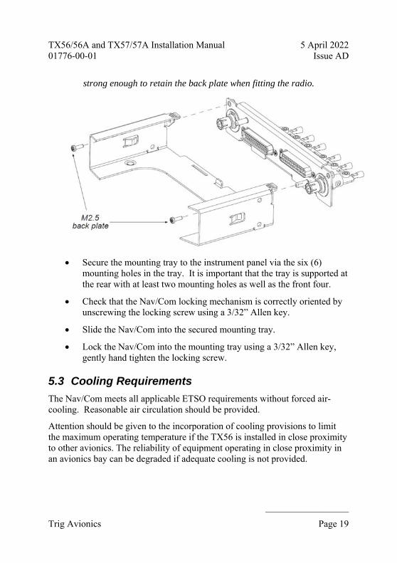
5.5.6 BNC Connections
Feed the supplied blind mate BNC connectors into the TX56 mounting tray back plate and attach the washer combination in the following order:
Wave washer (part number 00317-00).
Plain washer (part number 00241-00).
Circlip washer (part number 00242-00).
The Circlip washer should be fitted with a set of Circlip pliers.

TX56/56A and TX57/57A Installation Manual 5 April 2022 01776-00-01 Issue AD
______________________
Page 34 Trig Avionics
5.6 Interface Details
5.6.1 Speaker Output
The speaker output can drive a 4 ohm or greater cabin speaker. The speaker should be rated at 4 watts or higher. The speaker outputs received radio audio and the aux audio input, but not the music or the transmitter sidetone.
5.6.2 Headphone Outputs
The TX56 can drive two sets of headphones. The output is stereo and is intended for headsets of 150 to 600 ohm impedance.
The radio also works correctly when a mono headset is plugged into a stereo socket, or can be wired for mono headphones sockets.
5.6.3 Mono Com Audio Output
This output is used to drive a conventional 600 ohm audio panel input. Note that only the received radio audio and transmitter sidetone will be output; music and aux audio will NOT be present.
5.6.4 Transmit Interlock
When two communication radios are mounted in an aircraft the transmit interlock input of one can be connected to the transmit PTT key of the other radio. When the other radio transmitter is keyed, the squelch threshold of this radio is increased to minimise break-through between one radio and the other.
Note: To improve the performance when using two radios, the antennas should be as far apart as practical – for example on the top and bottom of the fuselage.
5.6.5 Lighting Bus Input
The TX56 will adjust the brightness of the front panel switch lighting according to the voltage on the lighting bus input. The lighting bus voltage is automatically adapted to the aircraft bus voltage.
If no lighting bus input is detected, the radio will automatically control the front panel lighting based on the ambient light sensor.

TX56/56A and TX57/57A Installation Manual 5 April 2022 01776-00-01 Issue AD
______________________
Trig Avionics Page 35
5.6.6 PTT1/2 Key Input
Two Push to Talk (PTT) inputs are provided, which correspond to the two microphone inputs. Only the corresponding microphone input is routed to the transmitter when the key switch is pressed.
The PTT1 input has priority over the PTT2 input – if the PTT1 switch is closed when the PTT2 switch is closed, the input from Microphone 1 is routed to the transmitter.
The inputs are active low, and will be asserted when the voltage to ground is pulled below approximately 4 volts. The input should be connected to a momentary switch on the yoke or on the microphone.
For retrofit installations where a single PTT input is shared for both microphone inputs, Single PTT mode can be enabled. See section 6.2.18 for more details.
5.6.7 Intercom Key Input
The intercom key switch input allows the intercom function to be selected using a remote switch, or permanently enabled by grounding the pin inside the connector. The input is active low, and will be asserted when the voltage to ground is pulled below approximately 4 volts.
If this pin is tied low, the intercom function depends on the vox operated squelch.
Note: It is possible to combine both the key switch and the vox activation, or to use only one. To use only the switch, wire the switch to the intercom key input and select the vox squelch to the lowest setting during configuration. To use only the vox, wire the intercom key input to ground, and configure the squelch accordingly.
5.6.8 Auxiliary Audio Input
This input is continually routed to the headphone and cabin speaker outputs. It is intended for annunciators and identification tones.

TX56/56A and TX57/57A Installation Manual 5 April 2022 01776-00-01 Issue AD
______________________
Page 36 Trig Avionics
5.6.9 Music Audio Input
This is a stereo input which is routed to the both headphone outputs and should be used for connecting an MP3 player or similar device. The music input volume is adjustable and the music mute options can be configured within the setup menu to allow the radio reception or transmission audio to take priority.
5.6.10 Microphone Input
Microphone connections should be made using shielded twisted pair cables.
The two microphone inputs are identical, and have a nominal sensitivity of 1Vrms to 5Vrms into a 600 ohm load. A 12V DC bias voltage is supplied by the radio to the microphone inputs to support a preamplifier in the microphone.
The microphone gains can be adjusted within the setup menu.
5.6.11 RS232 Input/Output
The RS232 input allows certain third-party multi-function displays to preload the standby and active frequencies and to monitor the Nav/Com status. The radio understands the Apollo SL30 protocol ($PMRRC and $PMRRV) and the Garmin GNC protocol ($PGRMC and $PGRMV), both of which are based on NMEA at a speed of 9600 bps.
5.6.12 Remote Flip-flop
This input is used to allow remote activation of the frequency change, and is typically used in a helicopter. The input is active low, and will be asserted when the voltage to ground is pulled below approximately 4 volts.
5.6.13 Nav Audio Output
This output is used to drive a conventional 600 ohm audio panel input. The pilot can switch between voice and ident modes which switches in an ident filter that passes only the 1020 Hz Morse identifier.
5.6.14 Nav Right/Left Output
The Course Deviation Indicator (CDI) Right/Left needle output can drive up to 5 indicators, each with 1 kohm nominal impedance. Full scale deflection is

TX56/56A and TX57/57A Installation Manual 5 April 2022 01776-00-01 Issue AD
______________________
Trig Avionics Page 37
±150mV. When the deviation is greater than 10 degrees or when full fly-left or fly-right indications are given, the voltage will exceed 150 mV.
5.6.15 Glideslope Up/Down Output
The CDI Up/Down needle output can also drive up to 5 indicators, each with 1 kohm nominal impedance. Full scale deflection is ±150mV. Full fly-up or fly-down indications will go beyond 150 mV.
5.6.16 To/From Flag +/- Output
The To/From output can drive up to 3 indicators, each with 200 ohm to 1 kohm nominal impedance. The maximum output is ±250mV.
5.6.17 Nav and Glideslope Valid Flag Outputs
The flag outputs can drive up to 5 indicators, each with nominal 1 kohm impedance. The output will drive not less than 260 mV for a valid indication.
5.6.18 ILS Energise Output
ILS Energise is an active low output that can sink up to 400 mA. It is low when an Instrument Landing System (ILS) frequency has been tuned in the primary position on the Nav receiver; it is high impedance when a VOR frequency is tuned. ILS energise is intended to activate an external glideslope receiver, and/or switch an indicator relay.
5.6.19 Back-Course Annunciator Output
Back Course is an active low output that can sink up to 400 mA. It is low when an ILS frequency has been tuned in the primary position on the Nav receiver and the pilot has selected the back-course function. It is intended to illuminate the BC annunciator on the CDI.
5.6.20 Superflag Outputs
The superflag outputs provide an active high voltage derived from the aircraft bus voltage. The output will be within 2 V of the bus voltage, and can source up to 400 mA. The voltage is high when the corresponding flag is NOT displayed. A weak pull-down returns the voltage to zero when the

TX56/56A and TX57/57A Installation Manual 5 April 2022 01776-00-01 Issue AD
______________________
Page 38 Trig Avionics
corresponding flag is displayed.
5.6.21 Composite Output
The composite VOR/LOC output has output voltage of 0.5 Vrms for VOR signals and 0.39 Vrms for localiser signals into a load impedance of 1 kohm. It is intended for connection to a CDI with built-in converter, or to an analogue converter unit for a digital CDI.
5.6.22 Switched Power
Switched power provides aircraft bus voltage whenever the Nav receiver is on. It can source up to 500 mA. It is intended to be used to power an external instrument or indicator.
5.6.23 Power Control
The Power Control output is an active low output that provides a low impedance path to ground when the Nav receiver is on. It can sink only 50 mA. It is intended to be used in conjunction with external switches or relays to enable an external instrument or indicator.
5.6.24 DME Interface
The DME interface provides 5 pins that correspond to the King serial Distance Measuring Equipment (DME) tuning interface.
DME Common is an input that is used to select between multiple Nav/Coms or other tuning sources. The Nav radio will only provide channel data if DME common is pulled low. RNAV Mode and RNAV Channel Request are alternate inputs which request the channel data from the Nav/Com.
DME Data and DME Clock are the bus outputs that send the tuning data to an attached DME.
5.6.25 OBS Interface
OBS H and OBS C are an output pair that sends a constant sine wave output to drive the Omni Bearing Selector (OBS) rotor. OBS D, E, F and G are the two input pairs sent back from the OBS stators to indicate the selected radial.

TX56/56A and TX57/57A Installation Manual 5 April 2022 01776-00-01 Issue AD
______________________
Trig Avionics Page 39
The OBS system will automatically adjust the level to achieve the correct sensitivity, but the individual instrument will need to be calibrated for bearing accuracy at installation.
5.6.26 Power Input
The TX56 power supply can be 11-33 volts DC; no voltage adjustment is required. The TX57 requires 22-33 volts DC. In both cases use a circuit breaker with a minimum value of 5 amps for the communications radio, and a circuit breaker with a minimum value of 3 amps for the navigation receiver.
In practice, higher value circuit breakers are often used, particularly if more than one device is sharing the circuit breaker. If a circuit breaker with a higher rating is used, the wiring gauge used should be increased appropriately.
The peak current consumption on transmit exceeds the current capability of a single pin on the 25 way connector. Both power inputs must be wired, and at least two ground returns must be wired. Use 20 AWG wire for the power connection wires.
The Nav receiver power consumption is lower, and a single 22 AWG wire on the 44 way connector is sufficient.
Note: The power consumption figures for the Nav/Com do not include current taken from the switched power output, or from the superflag outputs. If these outputs are used the current consumption from those outputs should be added to the Nav/Com current consumption when choosing wire sizes and circuit breaker capacity.
5.6.27 Ground Returns
There are only 3 ground pins on the 25 way connector, at pins 4, 9 and 17. Two of these ground pins should be used for the power input leaving the other ground pin for the audio grounds. Audio grounds should be connected together with a fly lead connected to the remaining ground pin using the ground screws on the mounting plate.
There are adequate ground pins on the 44 way connector to associate with the signals from that connector. Do not try to supplement the Com radio audio grounds by borrowing unused grounds from the 44 way connector, as this can couple noise into the audio signals.

TX56/56A and TX57/57A Installation Manual 5 April 2022 01776-00-01 Issue AD
______________________
Page 40 Trig Avionics
Refer to section 5.4 for further wiring considerations.

TX56/56A and TX57/57A Installation Manual 5 April 2022 01776-00-01 Issue AD
______________________
Trig Avionics Page 41
6. Installation Setup and Test
6.1 Initial Power On
The TX56 will display a splash screen when the radio is first switched on. The splash screen shows the software versions currently loaded and what model of radio is connected.
6.2 Configuration Items
There are a small number of installation parameters that can be adjusted. Those that are expected to be operated in flight are accessed by pressing and holding the MON button for approximately 2 seconds. Those that are infrequently accessed only appear when a second step is accomplished by pressing and holding the MEM button for 2 seconds after the in-flight settings screen is displayed.
The individual setup items are selected using the large tuning knob, and adjusted using the small tuning knob. Pressing MON again will exit from the setup mode.
The base set of parameters are:
Intercom Volume
Intercom Squelch
Music Volume
Music Muting
Frequency Step Size – enable/disable 8.33 kHz tuning. Not available on TX56A/57A
The items accessed on the second level of menu are:
Internal Nav Audio Routing
CDI Type
OBS Calibration
Remote Protocol Choice

TX56/56A and TX57/57A Installation Manual 5 April 2022 01776-00-01 Issue AD
______________________
Page 42 Trig Avionics
Auxiliary Input Volume
Auxiliary Input Muting
Sidetone Volume
Radio Squelch
Audio Test Tones
Microphone gain adjustment
Display Dim and Brightness settings
Single/Dual PTT configuration
Diagnostic Information Display
6.2.1 Intercom Volume
This setting controls the volume of the built-in intercom.
6.2.2 Intercom Squelch
The intercom includes a voice activated squelch control, to limit the background noise heard over the intercom. Increasing the squelch level requires a louder microphone input to turn on the intercom. If you set the intercom squelch to minimum (turning the knob anti clockwise), then you can speak quietly or at greater distance from the mic. If you have trouble with audible background noise opening the squelch when you’re not speaking, you can increase the squelch to make the radio to ignore background noise.
6.2.3 Music Volume
This setting controls the volume of the stereo music input. The listening level is controlled by this setting, and also by the volume controls on the music source. Set the music volume so that a reasonable level is achieved with the source set to a typical playback setting.
6.2.4 Music Muting
Turn this feature ON if the music should mute during radio reception. Turning

TX56/56A and TX57/57A Installation Manual 5 April 2022 01776-00-01 Issue AD
______________________
Trig Avionics Page 43
this feature off leaves the music playing during reception. The music always mutes when the radio is transmitting.
6.2.5 Frequency Step Size
The TX56/TX57 is capable of operating in both an 8.33 kHz and 25 kHz environment. If 8.33 kHz operation is not required, the 8.33 kHz channels can be disabled to simplify the tuning operation.
Note: 8.33 kHz operation is required in some European airspace.
The TX56A/TX57A are only capable of operating in a 25 kHz environment.
6.2.6 Internal Nav Audio Routing
If the Nav/Com is used in stand-alone mode (without an external audio panel), the Nav Audio voice and Morse ident can be routed to the headphone and speaker outputs.
When internal Nav audio is enabled, the audio choice cycles through Voice, Ident and muted, and the selected Nav audio signal will be heard in the headphone outputs.
When internal Nav audio is disabled, the audio choice cycles between Voice and Ident; audio routing is selected on an external audio panel.
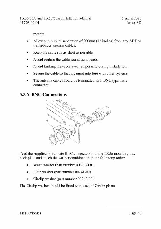
6.2.7 CDI Type
The Nav/Com can be used with several types of indicator. Select the appropriate style from the menu:
CDI Style Examples Menu Choice
Indicator with built-in converter KI204
Aspen ACU
CONVERTER
Simple indicator with OBS interface to Nav/Com
TI106 RESOLVER
RS232 Serial Interface Garmin G3X
SERIAL
TX56/56A and TX57/57A Installation Manual 5 April 2022 01776-00-01 Issue AD
______________________
Page 44 Trig Avionics
CDI Style Examples Menu Choice
No external device – using Nav/Com front panel
N/A INTERNAL
The choice of CDI also affects the behaviour of the Nav/Com.
Selecting CONVERTER means that the internal CDI display is disabled, and Nav dual watch is also not available.
Selecting RESOLVER or SERIAL means that the OBS for both the external device and the internal CDI is controlled by the external OBS knob.
6.2.8 OBS Calibration
If a resolver type of interface has been selected, you will be offered the choice of calibrating the device. Although they are set at the factory there are usually small variations in the OBS interface which can be corrected by the Nav/Com. Once selected, the calibration process involves selecting in turn twelve equally spaced bearings on the external instrument: 000°, 030°, 060°, 090°, 120° and so on up to 330°.
6.2.9 Remote Protocol Choice
The Nav/Com can emulate either the Apollo SL30 Nav/Com or the Garmin GNC255 Nav/Com. This allows compatibility with a wide range of third party systems. If available on the device you are connecting, for maximum feature support, including control of 8.33 kHz frequencies, choose the Garmin protocol.
6.2.10 Auxiliary Input Volume
The auxiliary input is a low-fidelity monophonic input intended for Nav radio ident inputs and simple annunciators. This setting controls the relative volume of the auxiliary audio input.
6.2.11 Auxiliary Input Muting
This allows the auxiliary input to be muted when the radio is receiving or transmitting speech. Turn this feature ON if the auxiliary input is being used

TX56/56A and TX57/57A Installation Manual 5 April 2022 01776-00-01 Issue AD
______________________
Trig Avionics Page 45
for non-essential services, like an MP3 player. Turn this feature OFF if the auxiliary input is being used for essential services like annunciators or traffic alerts.
6.2.12 Sidetone Volume
The audio sidetone is the transmitted audio signal; this setting controls the level of the sidetone in the headphones.
6.2.13 Radio Squelch
The receiver has a factory set nominal squelch point of approximately -95 dBm which should be appropriate for most installations. In some aircraft with noisy electrical environments, such as vintage or experimental aircraft, the factory setting may lead to nuisance squelch breaking.
The radio squelch allows the installer to moderately increase the squelch set point. The squelch point is indicated on the screen by a bar being filled in, higher values being represented by more of the bar being filled. Even with the radio squelch at its highest setting the unit will still meet its operating performance requirements. The radio range will not be significantly affected at maximum squelch.
6.2.14 Audio Test Tones
The audio test tones provide a simple way of testing that the installation is correctly wired. The radio has two stereo headphone outputs, a mono line output, and a cabin speaker output. The audio test tone generator sends a sequence of tones to each of those outputs in turn.
Use the small right hand knob to scroll through the output choices, and check that each output in turn is correct. The stereo music and intercom functions will appear in the wrong positions if the wiring is incorrect.
During the test the volume knob controls the active outputs.
6.2.15 Microphone gain adjustment
The factory set microphone adjustment provides a nominal sensitivity of 100 mV RMS which is compatible with most conventional aviation headset

TX56/56A and TX57/57A Installation Manual 5 April 2022 01776-00-01 Issue AD
______________________
Page 46 Trig Avionics
microphones. Automatic gain control takes care of variations in speaking voice and variation between different microphones. Microphone adjustment is therefore only required to correct for alternative installation choices. If the installation uses unusually high output microphones, or an audio panel with built-in amplification, the radio input can be overloaded and cause distortion on the transmitted audio. If the microphone output is too low, the transmitted modulation will be low, and may be unreadable. Each microphone input can be adjusted separately.
The microphone gain is adjusted in steps of 1 dB. The left end stop on the range corresponds to a nominal sensitivity of 200 mV; the right end stop corresponds to a nominal sensitivity of 6 mV. The factory original setting is 6 steps from the left of the range.
6.2.16 LCD Dim Point
The LCD backlight illumination is controlled automatically by the ambient light sensor. Depending on the amount of light spill in the cockpit, and the brightness of other adjacent avionics displays, it may be necessary to adjust the darkest setting of the backlight to best match other equipment and to improve the cockpit appearance at night.
Note – it is only practical to do this in pitch darkness, since that is the in-flight environment that you are trying to reproduce. If you are working in a hangar with any other lighting it may be better to leave the setting in the mid-range.
6.2.17 LCD Brightness Curve
The actual maximum brightness of the LCD cannot be increased with this control. What this control adjusts is the rate at which the lighting increases in brightness as the ambient light increases. This allows the brightness to be matched to other avionics displays during light level changes as far as possible.
6.2.18 Single PTT Mode
In the factory standard configuration pressing PTT1 sends only Mic 1 to the transmitter; PTT2 sends only Mic 2. For a retrofit installation, for example when replacing an SL30 radio, a single PTT is shared between the two microphones. Enabling Single PTT mode means that whenever PTT1 is pressed both Mic 1 and Mic 2 audio is sent to the transmitter.

TX56/56A and TX57/57A Installation Manual 5 April 2022 01776-00-01 Issue AD
______________________
Trig Avionics Page 47
6.2.19 Diagnostic Information Display
Displays system information to aid in troubleshooting and installation.
Sense Value from the front panel ambient light sensor.
Ctrl Value from the aircraft’s lighting bus.
Bus Displays the aircraft’s supply voltage as sensed by the Com radio.
Temp Temperature measured by the TX56 internal temperature sensor.
CM Number of entries used and available in the Com frequency database.
NV Number of entries used and available in the Nav frequency database.

TX56/56A and TX57/57A Installation Manual 5 April 2022 01776-00-01 Issue AD
______________________
Page 48 Trig Avionics
7. Post Installation Checks Post installation checks should be carried out in accordance with your certification requirements. These checks should include:
VHF Com receiver operation. Tune a local station and check that the reception is clear and understandable.
VHF navigation receiver operation. Using a ramp test set, make sure that VOR and LOC signals are being received, and that correct indications are shown on all connected instruments. Pay particular attention to flags, superflags, and annunciators.
Glideslope operation. Using a ramp test set, make sure that glideslope signals are being received, and that correct indications are shown on all connected instruments. Pay particular attention to flags and superflags.
DME channelling. If used, make sure that the DME can be tuned by the Nav/Com. If no convenient DME station as available on the airfield, you may need a DME ramp test set.
Transmitter operation and microphone gain adjustment. Contact a local station and check that they are receiving you clearly.
Interference check. Check the radio with other avionics and electrical equipment on the aircraft operating. Check at low, mid and high radio frequencies. There should be no significant interference on reception, and when the TX56/TX57 transmits there should be no adverse effect on any other equipment.
Sidetone adjustment. During the transmit checks, verify the sidetone level is set appropriately.
Intercom adjustment. If the intercom function is being used, set the listening level and squelch appropriately. Note that the squelch is best adjusted in the normal ambient noise environment, for example with the engine(s) running and developing power.

TX56/56A and TX57/57A Installation Manual 5 April 2022 01776-00-01 Issue AD
______________________
Trig Avionics Page 49
8. Normal Operation
8.1 Front Panel
8.2 Display Modes
The display is divided into two windows. The left part of the screen shows the primary and standby frequencies and icons to indicate the operating mode of the communication radio. The right part of the screen shows the primary and standby frequencies and icons to indicate the operating mode of the navigation radio. The controls are shared between the communication radio and the navigation radio; which is being controlled is shown by the size of the corresponding display window.
In communication radio mode, the dividing bar moves to the right and the communication radio window occupies most of the screen. When the display looks like that the knobs and buttons control the behaviour of the communication radio.
In navigation radio mode the dividing bar moves to the left and the navigation radio window occupies most of the screen. In navigation mode the knobs and buttons control the behaviour of the navigation radio.
8.3 Com Radio Display
Press the COM button to enable Com display mode. The primary Com

TX56/56A and TX57/57A Installation Manual 5 April 2022 01776-00-01 Issue AD
______________________
Page 50 Trig Avionics
frequency is on the left and the standby frequency is on the right half of the window.
The right hand concentric knobs are used to tune the radio. The large knob adjusts the MHz portion of the standby frequency, and the smaller knob adjusts the kHz portion of the standby frequency. To activate that frequency, press the Flip-flop button. This moves the standby frequency to the primary position, and puts the primary frequency into the standby position.
The TX icon shows that the radio is transmitting. An RX icon shows that the frequency is active and the audio will be heard through the headphone and speaker outputs. The standby frequency will only be received during the MONITOR function which is indicated by a +2 icon when active.
8.4 Nav Radio Display
Press the NAV button to enable Nav display mode. Like the Com radio window, the primary Nav frequency is on the left and the standby frequency is on the right. The right hand concentric knobs are used to tune the standby frequency, and the Flip-flop button exchanges the primary and standby frequencies.
The Nav receiver will automatically decode the received radial for a VOR if it is in range, and display it below the frequency. It will also automatically decode the Morse code identifier, and display that as well. The identifier is only displayed after it has been heard twice correctly, so there can be a delay
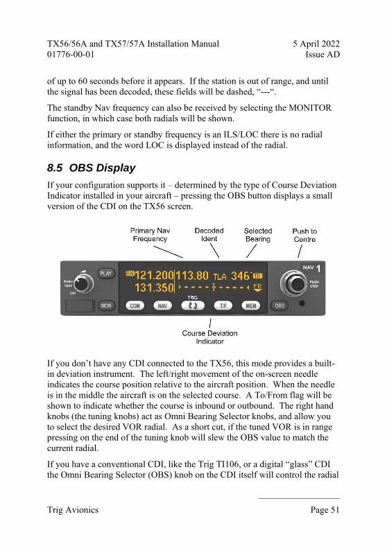
TX56/56A and TX57/57A Installation Manual 5 April 2022 01776-00-01 Issue AD
______________________
Trig Avionics Page 51
of up to 60 seconds before it appears. If the station is out of range, and until the signal has been decoded, these fields will be dashed, “---“.
The standby Nav frequency can also be received by selecting the MONITOR function, in which case both radials will be shown.
If either the primary or standby frequency is an ILS/LOC there is no radial information, and the word LOC is displayed instead of the radial.
8.5 OBS Display
If your configuration supports it – determined by the type of Course Deviation Indicator installed in your aircraft – pressing the OBS button displays a small version of the CDI on the TX56 screen.
If you don’t have any CDI connected to the TX56, this mode provides a built-in deviation instrument. The left/right movement of the on-screen needle indicates the course position relative to the aircraft position. When the needle is in the middle the aircraft is on the selected course. A To/From flag will be shown to indicate whether the course is inbound or outbound. The right hand knobs (the tuning knobs) act as Omni Bearing Selector knobs, and allow you to select the desired VOR radial. As a short cut, if the tuned VOR is in range pressing on the end of the tuning knob will slew the OBS value to match the current radial.
If you have a conventional CDI, like the Trig TI106, or a digital “glass” CDI the Omni Bearing Selector (OBS) knob on the CDI itself will control the radial

TX56/56A and TX57/57A Installation Manual 5 April 2022 01776-00-01 Issue AD
______________________
Page 52 Trig Avionics
selected for the TX56 CDI, and the left/right movement of the main CDI needle will be repeated on the screen of the TX56. The tuning knobs on the TX56 will have no effect.
If the tuned station is out of range, the CDI display will be crossed out and no left/right needle will be displayed.
If you have an external CDI which has its own built-in converter, such as a legacy Bendix/King indicator, OBS mode will not be available – you should use the external CDI in the usual way.
8.6 T/F (To/From) Button
When the Nav receiver is tuned to a VOR that is in range the system will decode the radial that you are flying over. The normal display is the radial from the beacon – that is, the outbound radial. If you want to see the magnetic track to follow to get to the beacon, pressing the T/F button will flip the display to show bearings to the beacon. Pressing again will toggle back to displaying the radial from the beacon.
8.7 Localizer Back-Course Approaches
In some parts of the world there are approaches based on tracking a localizer back course. The TX56 can automatically reverse the course indications for you, so that the CDI needle works in the correct sense. If a localizer frequency is active on the primary Nav channel, press and hold the T/F button for 5 seconds to turn on the back course sensing. An icon BC will be shown on the screen, and if you are using a Trig TI106 CDI, a BC annunciation will also appear on the CDI.
8.8 On/Off, Volume, Squelch, Ident Knob
The left hand knob controls the power to the radio and adjusts the audio volume. Turning this knob clockwise will switch on the radio and then increase the volume. Turning anticlockwise will reduce the volume and eventually will click off. Both the Com radio and Nav radio volume are controlled at the same time, whichever screen is showing.
When the display is in communication radio mode, pressing the end of this knob toggles the automatic squelch on and off, which can be used to listen for

TX56/56A and TX57/57A Installation Manual 5 April 2022 01776-00-01 Issue AD
______________________
Trig Avionics Page 53
faint stations or as a simple audio test.
When the display is in navigation radio mode, pressing this knob toggles between voice mode and ident mode on the Nav radio receiver. Voice mode is used to listen to ATIS or other communications on a VOR station. In voice mode the display shows a V icon. Ident mode filters out most of the background noise (and voice transmission) and allows you to listen just to the Morse code identifier. This is especially useful when the signal is faint. Ident mode shows an ID icon.
If the TX56 has been configured for stand-alone use without an audio panel, a third choice is available which is to mute the Nav audio altogether – neither icon is shown in this case. Press the knob in Nav mode to cycle through the choices.
The internal decode of Morse code identifiers does not depend on the setting of the audio output.
8.9 Com Radio Tuning Step Size
When tuning in Com mode, pressing the end of the tuning knob changes the channel spacing that the small knob operates through. If the radio is configured for 8.33 kHz operation, the steps toggle between 8.33 kHz channels and 25 kHz channels. If the radio is configured only for 25 kHz operation, the steps toggle between 25 kHz and 50 kHz channels.
Changing the step size does not change the behaviour of the radio, only the tuning knob step size – it helps to quickly tune a frequency.
The TX56A does not support 8.33 kHz operation and so the steps will only toggle between 25 kHz and 50 kHz; again, changing the step size does not change the behaviour of the radio and only changes the step size between 25 kHz and 50 kHz.
8.10 MON Button
The Com and Nav radios include a dual-frequency listen feature; pressing the MON button toggles this feature on and off. The monitor mode can be enabled separately for the Com and Nav radios; press the MON button whilst on the appropriate screen.

TX56/56A and TX57/57A Installation Manual 5 April 2022 01776-00-01 Issue AD
______________________
Page 54 Trig Avionics
When the Com monitor is active, a +2 icon appears next to the standby frequency, and the radio will scan between the active and standby frequencies listening for transmissions. The primary channel has priority – a transmission on the primary channel will interrupt the secondary channel. As an aid to identifying which channel is active, the RX icon will light next to the active channel and the secondary channel will appear slightly quieter than the primary. If your radio is wired for stereo and you are using a stereo headset, the secondary channel will also appear to be to the right of the primary channel.
This is useful in an aircraft with only a single radio since it allows you, for example, to copy the ATIS whilst maintaining a listening watch on the ATC frequency.
When the Nav mode is active, pressing the MON button activates the standby VOR frequency and displays the radial of the standby VOR. This allows you to find an intersection of two beacons with only a single TX56 receiver. The primary VOR/LOC will be displayed as usual on your CDI, whilst the secondary radial can be read on the screen.

TX56/56A and TX57/57A Installation Manual 5 April 2022 01776-00-01 Issue AD
______________________
Trig Avionics Page 55
Dual watch is also available when you are using the internal CDI display. The primary Nav channel (LOC or VOR) will be shown on a small CDI display while the secondary VOR is also decoded and displayed.
Nav dual frequency operation is not possible if the primary CDI has a built-in converter, such as a legacy CDI or an Aspen PFD.
During dual frequency operation you cannot listen to the Ident for verification, and the TX56 will not identify the beacon for you. You should always verify you have the correct beacons tuned before you switch to monitoring both.

TX56/56A and TX57/57A Installation Manual 5 April 2022 01776-00-01 Issue AD
______________________
Page 56 Trig Avionics
8.11 PLAY Button
The Com radio includes a digital audio recorder. Pressing the PLAY button will automatically replay the previous transmission received from ATC. During playback the PB icon will be displayed on the screen.
If a new transmission is received during playback, the playback is cancelled and the live transmission will be heard instead.
8.12 Intercom Function
The TX56 radio has a built in intercom which can be installed as permanently engaged or selected via a switch. The intercom is voice activated and the audio is routed through to both of the headsets. The intercom squelch and volume can be adjusted independently from the radio function through the configuration menu.
8.13 Frequency Database
The TX56 has up to three types of database containing frequencies and station identifiers for both Com and Nav frequencies. One is stored in the radio and configured by the pilot; it will always be available. One is a list of the ten most recently used frequencies; it will be populated automatically as you use the radio. The third is only available if your Nav/Com has been connected to a compatible GPS receiver, and contains frequencies loaded from the GPS database.
Note that the TX56A is only able to store and recall 25 kHz Com channel frequencies.
To access these databases press the MEM button whilst in the applicable mode – there are Com databases and there are Nav databases. The right hand part of the window will be replaced with the database screen which always starts on the pilot created database.
The large knob moves the highlighted cursor, whilst the small knob selects the value at the cursor.

TX56/56A and TX57/57A Installation Manual 5 April 2022 01776-00-01 Issue AD
______________________
Trig Avionics Page 57
Airfield or facility identifiers are in alphabetical order. Scroll through the identifiers until you find the one that you want. Move the cursor using the large knob to highlight the station type, for example GND, TWR or APPR.
Pressing the MEM button at any time puts the currently selected result into the standby frequency and returns to the normal operating screen. Pressing the Flip-Flop button puts the currently selected result into the active frequency instead, and returns to the normal operating screen.
8.14 Recent Frequencies
There is also a memory of the ten most recent frequencies that you have used. From the initial memory screen, move the cursor using the large knob to highlight the MEMORY caption, and turn the small knob to select the RECENT database.
Move the highlight onto the frequency, and you can scroll through the ten most recently used frequencies.
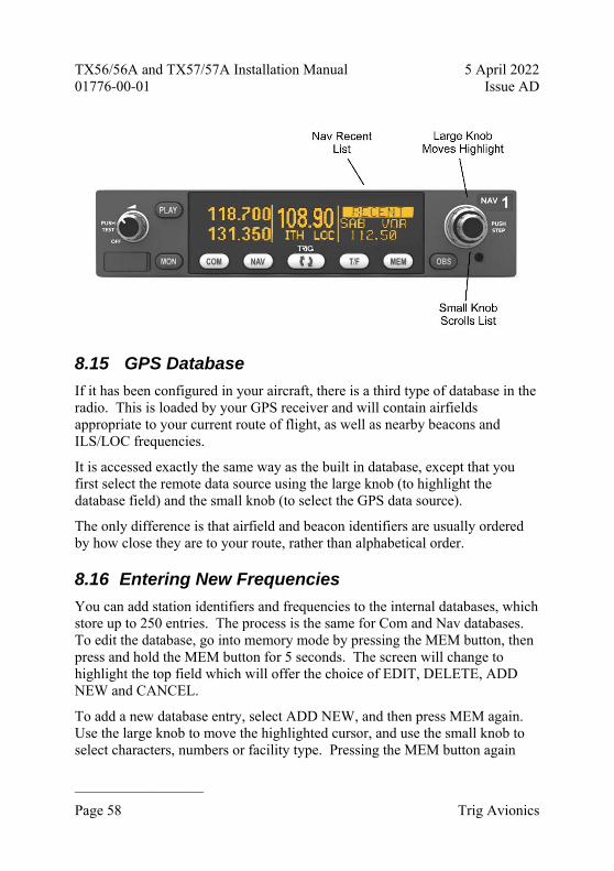
TX56/56A and TX57/57A Installation Manual 5 April 2022 01776-00-01 Issue AD
______________________
Page 58 Trig Avionics
8.15 GPS Database
If it has been configured in your aircraft, there is a third type of database in the radio. This is loaded by your GPS receiver and will contain airfields appropriate to your current route of flight, as well as nearby beacons and ILS/LOC frequencies.
It is accessed exactly the same way as the built in database, except that you first select the remote data source using the large knob (to highlight the database field) and the small knob (to select the GPS data source).
The only difference is that airfield and beacon identifiers are usually ordered by how close they are to your route, rather than alphabetical order.
8.16 Entering New Frequencies
You can add station identifiers and frequencies to the internal databases, which store up to 250 entries. The process is the same for Com and Nav databases. To edit the database, go into memory mode by pressing the MEM button, then press and hold the MEM button for 5 seconds. The screen will change to highlight the top field which will offer the choice of EDIT, DELETE, ADD NEW and CANCEL.
To add a new database entry, select ADD NEW, and then press MEM again. Use the large knob to move the highlighted cursor, and use the small knob to select characters, numbers or facility type. Pressing the MEM button again

TX56/56A and TX57/57A Installation Manual 5 April 2022 01776-00-01 Issue AD
______________________
Trig Avionics Page 59
stores the new value, and returns to the normal memory mode.
If you already have entries in the database, you can edit them to change the details, or you can delete them. To do that, first find the entry that you want to edit or delete using the normal memory mode. Then, with the entry you want to change displayed, press and hold the MEM button for 5 seconds. The choices described earlier will be offered; EDIT, DELETE, ADD NEW or CANCEL.
If you choose EDIT, and press MEM, the cursor can alter characters, numbers or facility type in the current entry. Pressing MEM will save that changed entry. If you choose DELETE, and press MEM, the current entry will be deleted.
If you get this far and realise that you did not want to change the database at all, select CANCEL and then press MEM; you will be returned to the normal memory mode.
8.17 Saving and Loading the Frequency Database
The frequency database entries you have made can be saved to a USB memory stick, or you can load a database from a USB stick. To load or save to USB, you need to put the USB memory stick into the radio before you switch on. When the radio detects the USB device it will offer to save or load your database. If there are data entries already on the radio you will be offered the choice to replace the whole database, or add entries from the USB stick.

TX56/56A and TX57/57A Installation Manual 5 April 2022 01776-00-01 Issue AD
______________________
Page 60 Trig Avionics
Similarly if there is already a database on the USB stick you can either overwrite it or add the radio data to the existing file.
To return to normal radio operation remove the USB device and switch the radio off and back on again.
In normal radio operation the USB port is powered off.
8.18 Configuration Mode
Additional setup items can be accessed by holding down the MON button for 3 seconds. The menu options can be selected using the larger tuning knob and the parameter value can be altered using the smaller tuning knob.
Intercom Volume Sets the intercom volume level
Intercom Squelch Sets the sensitivity of the intercom voice operated squelch
Music Volume Sets the volume level of the music input
Music Muting Mutes the music audio when a VHF transmission is received by the radio
Enable 8.33 kHz (TX56/TX57 only)
Turns on or off the ability to tune 8.33 kHz stations. If you are operating in an area with no 8.33 kHz service, turning off the 8.33 kHz channels allows quicker tuning of 25 kHz and 50 kHz steps. The

TX56/56A and TX57/57A Installation Manual 5 April 2022 01776-00-01 Issue AD
______________________
Trig Avionics Page 61
TX56A/57A are not 8.33 kHz capable and so this option will not be available.
When you have finished making changes, press the MON button again to return to normal operation.
8.19 General Low Temperature Operation
The Nav/Com is certified to operate correctly down to -20°C, but at low temperatures the display may be impaired. On a cold day you may need to wait for the cockpit to warm up to ensure normal operation.
8.20 Warning Messages
If the Nav/Com detects a problem, the screen will indicate WARNING and a brief statement of the problem. Depending on the nature of the problem, your radio may not be working properly. Note the message on the screen and pass that information to your avionics maintenance organisation. Press the flip-flop button to clear the message.
The following warnings may be seen:
Radio Hot The radio is overheating.
Stuck Mic A PTT switch has been closed for more than 35 seconds and the transmitter has stopped to avoid blocking the channel.
Low Volt The aircraft power input is below 10 volts (TX56/56A) or 16 volts (TX57/TX57A).
Ant Fault There is a problem with the aircraft communication antenna. The radio will still try to transmit, but you may not be heard.
Tx Fail There is a problem with the transmitter and the radio gave up trying. You may still be able to receive but not transmit.
OBS Lost The navigation receiver has lost the input from the OBS knob on the CDI. The CDI will flag and you will not be able to use it. Radials will still be displayed on the Nav/Com screen.
No Nav The navigation receiver has failed. No Nav functions will be

TX56/56A and TX57/57A Installation Manual 5 April 2022 01776-00-01 Issue AD
______________________
Page 62 Trig Avionics
available, but the Com radio will continue to operate normally.
8.21 Fault Annunciation
If the VHF radio detects a catastrophic internal failure, the screen will indicate FAULT and a brief statement of the problem. Note the FAULT message at the bottom of the screen and pass that information to your avionics maintenance organisation. The fault may be cleared by re-cycling the power to the radio but if the fault is still present the message will reappear.

TX56/56A and TX57/57A Installation Manual 5 April 2022 01776-00-01 Issue AD
______________________
Trig Avionics Page 63
9. Continued Airworthiness Other than for periodic functional checks required by the regulations, the TX56/TX57 Nav/Com has been designed and manufactured to allow “on condition maintenance”. This means that there are no periodic service requirements necessary to maintain continued airworthiness, and no maintenance is required until the equipment does not properly perform its intended function. When service is required, a complete performance test should be accomplished following any repair action. Repairs should only be carried out in accordance with Trig Avionics service procedures.
9.1 Cleaning the Front Panel
The front panel body and switches should be cleaned with a soft cotton cloth moistened with clean water. The LCD screen should be lightly cleaned with a lint free cloth taking care not to scratch the surface.

TX56/56A and TX57/57A Installation Manual 5 April 2022 01776-00-01 Issue AD
______________________
Page 64 Trig Avionics
10. Limited Warranty Trig Avionics warrants our products to be free from defects in materials and workmanship for a period of two (2) years from the date of installation by an authorised dealer.
This warranty covers repair and/or replacement at our option, of any parts found to be defective, provided such defects in our opinion are due to faulty material or workmanship and are not caused by tampering, abuse, or normal wear.
All warranties are F.O.B.
Trig Avionics Limited Trig Avionics Europe B.V. Heriot Watt Research Park Hardwareweg 3 Riccarton, Edinburgh, EH14 4AP 3821 BL Amersfoort, Netherlands
Trig Avionics will not accept or pay for any charges for warranty work performed outside our factory without prior written consent.
This warranty applies only to products in normal use. It does not apply to units or circuit boards defective due to improper installation, physical damage, tampering, lightning or other electrical discharge, units with altered serial numbers, or units repaired by unauthorised persons or in violation of Trig Avionics service procedures.
Trig Avionics assumes no responsibility for any consequential losses of any nature with respect to any products or services sold, rendered, or delivered.

TX56/56A and TX57/57A Installation Manual 5 April 2022 01776-00-01 Issue AD
______________________
Trig Avionics Page 65
11. Environmental Qualification Forms
Nomenclature: TX56 Nav/Com
Part Number: 01576-00-xx
ETSO: 2C169a, 2C128, 2C34f, 2C36f and 2C40c
Manufacturer: Trig Avionics Europe B.V.
Address: Hardwareweg 3, 3821 BL Amersfoort, Netherlands
Conditions DO-160G
Description of Conducted Tests
Temperature and Altitude 4.0 Equipment tested to Categories: A4, C4
Low temperature ground survival
4.5.1 -55°C
Low temperature operating
4.5.2 -20°C
High temperature operating
4.5.4 +55°C
High temperature short-time operating
4.5.3 +70°C
High temperature ground survival
4.5.3 +85°C
Loss of Cooling 4.5.5 Cooling air not required (+70°C operating without cooling air)
Altitude 4.6.1 55,000 feet
Decompression 4.6.2 8,000 to 55,000 feet in 15 seconds
Overpressure 4.6.3 -15000 feet
Temperature Variation 5.0 Equipment tested to Category C
Humidity 6.0 Equipment tested to Category A
Operational Shocks 7.2 Equipment tested to Category B
Crash Safety 7.3 Equipment tested to Category B
Vibration 8.0 Aircraft zone 2; type 3, 4, 5 to category S level M; type 1 (Helicopters) to category U level G

TX56/56A and TX57/57A Installation Manual 5 April 2022 01776-00-01 Issue AD
______________________
Page 66 Trig Avionics
Explosion 9.0 Equipment identified as Category X – no test required
Waterproofness 10.0 Equipment identified as Category X – no test required
Fluids Susceptibility 11.0 Equipment identified as Category X – no test required
Sand and Dust 12.0 Equipment identified as Category X – no test required
Fungus 13.0 Equipment identified as Category X – no test required
Salt Spray 14.0 Equipment identified as Category X – no test required
Magnetic Effect 15.0 Equipment tested to Category Z
Power Input 16.0 Equipment tested to Category BX
Voltage Spike 17.0 Equipment tested to Category B
Audio frequency conducted susceptibility
18.0 Equipment tested to Category B
Induced signal susceptibility
19.0 Equipment tested to Category AC
Radio frequency susceptibility
20.0 Equipment tested to Category TT
Radio frequency emission 21.0 Equipment tested to Category B
Lightning induced transient susceptibility
22.0 Equipment tested to Category B2H2L2
Lightning direct effects 23.0 Equipment identified as Category X – no test required
Icing 24.0 Equipment identified as Category X – no test required
Electrostatic Discharge 25.0 Equipment tested to Category A
Fire, Flammability 26.0 Equipment identified as Category C

TX56/56A and TX57/57A Installation Manual 5 April 2022 01776-00-01 Issue AD
______________________
Trig Avionics Page 67
Nomenclature: TX56A Nav/Com
Part Number: 01954-00-xx
ETSO: 2C169a, 2C128, 2C34f, 2C36f and 2C40c
Manufacturer: Trig Avionics Europe B.V.
Address: Hardwareweg 3, 3821 BL Amersfoort, Netherlands
Conditions DO-160G
Description of Conducted Tests
Temperature and Altitude 4.0 Equipment tested to Categories: A4, C4
Low temperature ground survival
4.5.1 -55°C
Low temperature operating
4.5.2 -20°C
High temperature operating
4.5.4 +55°C
High temperature short-time operating
4.5.3 +70°C
High temperature ground survival
4.5.3 +85°C
Loss of Cooling 4.5.5 Cooling air not required (+70°C operating without cooling air)
Altitude 4.6.1 55,000 feet
Decompression 4.6.2 8,000 to 55,000 feet in 15 seconds
Overpressure 4.6.3 -15000 feet
Temperature Variation 5.0 Equipment tested to Category C
Humidity 6.0 Equipment tested to Category A
Operational Shocks 7.2 Equipment tested to Category B
Crash Safety 7.3 Equipment tested to Category B
Vibration 8.0 Aircraft zone 2; type 3, 4, 5 to category S level M; type 1 (Helicopters) to category U level G
Explosion 9.0 Equipment identified as Category X – no test required
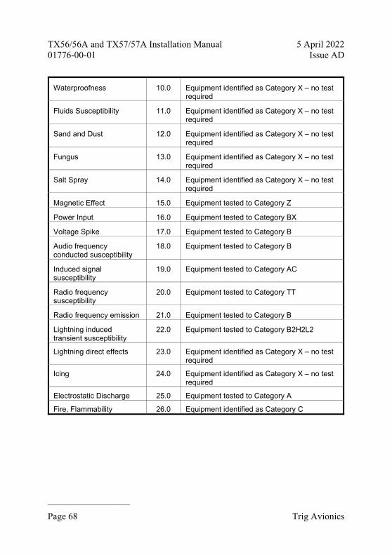
TX56/56A and TX57/57A Installation Manual 5 April 2022 01776-00-01 Issue AD
______________________
Page 68 Trig Avionics
Waterproofness 10.0 Equipment identified as Category X – no test required
Fluids Susceptibility 11.0 Equipment identified as Category X – no test required
Sand and Dust 12.0 Equipment identified as Category X – no test required
Fungus 13.0 Equipment identified as Category X – no test required
Salt Spray 14.0 Equipment identified as Category X – no test required
Magnetic Effect 15.0 Equipment tested to Category Z
Power Input 16.0 Equipment tested to Category BX
Voltage Spike 17.0 Equipment tested to Category B
Audio frequency conducted susceptibility
18.0 Equipment tested to Category B
Induced signal susceptibility
19.0 Equipment tested to Category AC
Radio frequency susceptibility
20.0 Equipment tested to Category TT
Radio frequency emission 21.0 Equipment tested to Category B
Lightning induced transient susceptibility
22.0 Equipment tested to Category B2H2L2
Lightning direct effects 23.0 Equipment identified as Category X – no test required
Icing 24.0 Equipment identified as Category X – no test required
Electrostatic Discharge 25.0 Equipment tested to Category A
Fire, Flammability 26.0 Equipment identified as Category C

TX56/56A and TX57/57A Installation Manual 5 April 2022 01776-00-01 Issue AD
______________________
Trig Avionics Page 69
Nomenclature: TX57 Nav/Com
Part Number: 01578-00-xx
ETSO: 2C169a, 2C128, 2C34f, 2C36f and 2C40c
Manufacturer: Trig Avionics Europe B.V.
Address: Hardwareweg 3, 3821 BL Amersfoort, Netherlands
Conditions DO-160G
Description of Conducted Tests
Temperature and Altitude 4.0 Equipment tested to Categories: A4, C4
Low temperature ground survival
4.5.1 -55°C
Low temperature operating
4.5.2 -20°C
High temperature operating
4.5.4 +55°C
High temperature short-time operating
4.5.3 +70°C
High temperature ground survival
4.5.3 +85°C
Loss of Cooling 4.5.5 Cooling air not required (+70°C operating without cooling air)
Altitude 4.6.1 55,000 feet
Decompression 4.6.2 8,000 to 55,000 feet in 15 seconds
Overpressure 4.6.3 -15000 feet
Temperature Variation 5.0 Equipment tested to Category C
Humidity 6.0 Equipment tested to Category A
Operational Shocks 7.2 Equipment tested to Category B
Crash Safety 7.3 Equipment tested to Category B
Vibration 8.0 Aircraft zone 2; type 3, 4, 5 to category S level M; type 1 (Helicopters) to category U level G
Explosion 9.0 Equipment identified as Category X – no test required

TX56/56A and TX57/57A Installation Manual 5 April 2022 01776-00-01 Issue AD
______________________
Page 70 Trig Avionics
Waterproofness 10.0 Equipment identified as Category X – no test required
Fluids Susceptibility 11.0 Equipment identified as Category X – no test required
Sand and Dust 12.0 Equipment identified as Category X – no test required
Fungus 13.0 Equipment identified as Category X – no test required
Salt Spray 14.0 Equipment identified as Category X – no test required
Magnetic Effect 15.0 Equipment tested to Category Z
Power Input 16.0 Equipment tested to Category BX
Voltage Spike 17.0 Equipment tested to Category B
Audio frequency conducted susceptibility
18.0 Equipment tested to Category B
Induced signal susceptibility
19.0 Equipment tested to Category AC
Radio frequency susceptibility
20.0 Equipment tested to Category TT
Radio frequency emission 21.0 Equipment tested to Category B
Lightning induced transient susceptibility
22.0 Equipment tested to Category B2H2L2
Lightning direct effects 23.0 Equipment identified as Category X – no test required
Icing 24.0 Equipment identified as Category X – no test required
Electrostatic Discharge 25.0 Equipment tested to Category A
Fire, Flammability 26.0 Equipment identified as Category C
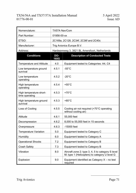
TX56/56A and TX57/57A Installation Manual 5 April 2022 01776-00-01 Issue AD
______________________
Trig Avionics Page 71
Nomenclature: TX57A Nav/Com
Part Number: 01956-00-xx
ETSO: 2C169a, 2C128, 2C34f, 2C36f and 2C40c
Manufacturer: Trig Avionics Europe B.V.
Address: Hardwareweg 3, 3821 BL Amersfoort, Netherlands
Conditions DO-160G
Description of Conducted Tests
Temperature and Altitude 4.0 Equipment tested to Categories: A4, C4
Low temperature ground survival
4.5.1 -55°C
Low temperature operating
4.5.2 -20°C
High temperature operating
4.5.4 +55°C
High temperature short-time operating
4.5.3 +70°C
High temperature ground survival
4.5.3 +85°C
Loss of Cooling 4.5.5 Cooling air not required (+70°C operating without cooling air)
Altitude 4.6.1 55,000 feet
Decompression 4.6.2 8,000 to 55,000 feet in 15 seconds
Overpressure 4.6.3 -15000 feet
Temperature Variation 5.0 Equipment tested to Category C
Humidity 6.0 Equipment tested to Category A
Operational Shocks 7.2 Equipment tested to Category B
Crash Safety 7.3 Equipment tested to Category B
Vibration 8.0 Aircraft zone 2; type 3, 4, 5 to category S level M; type 1 (Helicopters) to category U level G
Explosion 9.0 Equipment identified as Category X – no test required

TX56/56A and TX57/57A Installation Manual 5 April 2022 01776-00-01 Issue AD
______________________
Page 72 Trig Avionics
Waterproofness 10.0 Equipment identified as Category X – no test required
Fluids Susceptibility 11.0 Equipment identified as Category X – no test required
Sand and Dust 12.0 Equipment identified as Category X – no test required
Fungus 13.0 Equipment identified as Category X – no test required
Salt Spray 14.0 Equipment identified as Category X – no test required
Magnetic Effect 15.0 Equipment tested to Category Z
Power Input 16.0 Equipment tested to Category BX
Voltage Spike 17.0 Equipment tested to Category B
Audio frequency conducted susceptibility
18.0 Equipment tested to Category B
Induced signal susceptibility
19.0 Equipment tested to Category AC
Radio frequency susceptibility
20.0 Equipment tested to Category TT
Radio frequency emission 21.0 Equipment tested to Category B
Lightning induced transient susceptibility
22.0 Equipment tested to Category B2H2L2
Lightning direct effects 23.0 Equipment identified as Category X – no test required
Icing 24.0 Equipment identified as Category X – no test required
Electrostatic Discharge 25.0 Equipment tested to Category A
Fire, Flammability 26.0 Equipment identified as Category C

TX56/56A and TX57/57A Installation Manual 5 April 2022 01776-00-01 Issue AD
__________________
Trig Avionics Page 73
12. Installation Drawings
Dimensions in (--) are millimetres, dimensions in [--] are inches.
158.90 mm
CUT OUT DIMENSIONS FOR BEHIND AIRCRAFT PANEL MOUNT
31.5
0 m
m
160.30 mm
CUT OUT DIMENSIONS FOR FRONT AIRCRAFT PANEL MOUNT
33.8
0 m
m
CENTER OF GRAVITY (COG)

TX56/56A and TX57/57A Installation Manual 5 April 2022 01776-00-01 Issue AD
______________________
Page 74 Trig Avionics
ITEM DESCRIPTION QTY
1 TX56 Nav/Com 1
2 TX56 Mounting Tray 1
3 TX56 Mounting Tray Back Plate 1
4 Screw M2.5 x 8mm, pan Pozidriv 2

TX56/56A and TX57/57A Installation Manual 5 April 2022 01776-00-01 Issue AD
__________________
Trig Avionics Page 75
13. Wiring Diagrams Figure 1 - Overview of Typical Installation ..................................................... 77
Figure 2 - Stand-alone Installation (no Audio Panel) ...................................... 78
Figure 3 - Arrangements for VOR/LOC/GS Antenna Feed ............................. 79
Figure 4 – Channelling King panel mount serial DME.................................... 80
Figure 5 - Audio Panel Connections ................................................................ 81
Figure 6 - CDI Connections ............................................................................. 82

TX56/56A and TX57/57A Installation Manual 5 April 2022 01776-00-01 Issue AD
______________________
Page 76 Trig Avionics
This page intentionally left blank

TX56/56A and TX57/57A Installation Manual 5 April 2022 01776-00-01 Issue AD
__________________
Trig Avionics Page 77
AIRCRAFT POWER INAIRCRAFT POWER INAIRCRAFT GROUNDAIRCRAFT GROUND
LIGHTING BUS IN
RS232 INRS232 OUT
REMOTE FLIP‐FLOP
PTT1MICROPHONE 1
MONO AUDIO OUT
GROUND
NAV AUDIOGROUND
RIGHTLEFTUP
DOWNTO
FROMNAV VALIDGROUNDGS VALIDGROUND
BACK COURSEGROUND
RESOLVER ROTOR HRESOLVER ROTOR CRESOLVER STATOR DRESOLVER STATOR ERESOLVER STATOR FRESOLVER STATOR G
AIRCRAFT POWER INAIRCRAFT GROUND
ANTENNA
ANTENNA
1325948
1211
21
2318
7
17
TX56 Nav/Com
BNC
BNC
45
67891011121325263230
394043444142
117
5A CIRCUIT BREAKER
11 – 33V AIRCRAFT POWER
AIRCRAFT GROUND
11 – 33V AIRCRAFT POWER
LIGHTING BUS (14V or 28V)
MOUNTING TRAY GROUND STUDS
COM ANTENNA
NAV ANTENNA
3A CIRCUIT BREAKER
RS232 OUTRS232 INGROUND
MFD/GPS
COM1 MIC KEYCOM1 MIC AUDIO HICOM1 MIC AUDIO LO
COM1 AUDIO IN HICOM1 AUDIO IN LO
NAV1 AUDIO IN HINAV1 AUDIO IN LO
Audio Panel
+RIGHT Nav Indicator+LEFT+UP+DOWN+TO+FROM+VOR/LOC VALID‐VOR/LOC VALID+GLIDESLOPE VALID‐GLIDESLOPE VALIDBC ANNUNCIATORGROUND
OBS RESOLVER HOBS RESOLVER COBS RESOLVER DOBS RESOLVER EOBS RESOLVER FOBS RESOLVER G
OPTIONAL
Notes All wires 24 AWG or larger except Com power and ground 20 AWG, Nav power and ground 22 AWG.
Figure 1 - Overview of Typical Installation

TX56/56A and TX57/57A Installation Manual 5 April 2022 01776-00-01 Issue AD
______________________
Page 78 Trig Avionics
AIRCRAFT POWER INAIRCRAFT POWER INAIRCRAFT GROUNDAIRCRAFT GROUND
AUXILLIARY AUDIO
LIGHTING BUS IN
INTERCOM KEY
PTT1
PTT2
CABIN SPEAKER
HEADPHONE 1 LEFTHEADPHONE 1 RIGHT
HEADPHONE 2 LEFTHEADPHONE 2 RIGHT
MICROPHONE 1
MICROPHONE 2
GROUND
AIRCRAFT POWER INAIRCRAFT GROUND
ANTENNA
ANTENNA
132594
14
8
22
23
24
1
23
56
18
19
17
TX56 Nav/Com
BNC
BNC
117
5A CIRCUIT BREAKER
11 – 33V AIRCRAFT POWER
AIRCRAFT GROUND
11 – 33V AIRCRAFT POWER
AUX AUDIO INPUT
LIGHTING BUS (14V or 28V)
PILOTS PTT
COPILOTS PTT
CABIN SPEAKER
PILOTS HEADPHONES
COPILOTS HEADPHONES
PILOTS MICROPHONE
COPILOTS MICROPHONE
MOUNTING TRAY GROUND STUDS
COM ANTENNA
NAV ANTENNA
3A CIRCUIT BREAKER
1
2
3
25 Way
Notes All wires 24 AWG or larger except Com power and ground 20 AWG, Nav power and ground 22 AWG.
1. Auxiliary audio input can be used for alert tones. 2. Intercom is enabled when this pin is grounded. A key switch can be added as an intercom
PTT. Leaving this pin unconnected disables the intercom. 3. All audio grounds should be connected to one of the ground lugs on the mounting tray back
plate with a wire connecting to pin 4 on the same lug. Use the remaining ground lugs to terminate shield connections.
Figure 2 - Stand-alone Installation (no Audio Panel)
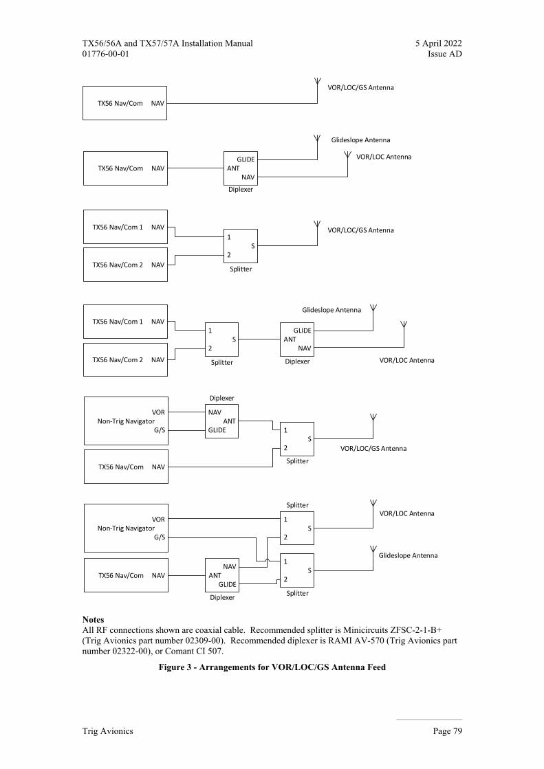
TX56/56A and TX57/57A Installation Manual 5 April 2022 01776-00-01 Issue AD
__________________
Trig Avionics Page 79
TX56 Nav/Com NAVGLIDE
ANTNAV
TX56 Nav/Com 1 NAV
1S
2
TX56 Nav/Com 2 NAV
TX56 Nav/Com 1 NAV1
S2
TX56 Nav/Com 2 NAV
GLIDEANT
NAV
TX56 Nav/Com NAV
VORNon‐Trig Navigator
G/S
TX56 Nav/Com NAV
NAVANT
GLIDE 1S
2
VORNon‐Trig Navigator
G/S
TX56 Nav/Com NAVNAV
ANTGLIDE
1S
2
1S
2
VOR/LOC Antenna
VOR/LOC Antenna
Glideslope Antenna
VOR/LOC Antenna
Glideslope Antenna
Glideslope Antenna
VOR/LOC/GS Antenna
VOR/LOC/GS Antenna
VOR/LOC/GS Antenna
Diplexer
Splitter
Splitter
Splitter
Splitter
Splitter
Diplexer
Diplexer
Diplexer
Notes All RF connections shown are coaxial cable. Recommended splitter is Minicircuits ZFSC-2-1-B+ (Trig Avionics part number 02309-00). Recommended diplexer is RAMI AV-570 (Trig Avionics part number 02322-00), or Comant CI 507.
Figure 3 - Arrangements for VOR/LOC/GS Antenna Feed

TX56/56A and TX57/57A Installation Manual 5 April 2022 01776-00-01 Issue AD
______________________
Page 80 Trig Avionics
GROUND
DME CLOCK
DME DATA
RNAV CHAN REQ
DME COMMON
RNAV MODE
36
35
37
38
23
4
TX56 Nav/Com 1
DME CLOCK
DME DATA
RNAV/CHAN REQ
GROUND
DME COMMON
KN62/62A/64
14
13
L
S
C
GROUND
DME CLOCK
DME DATA
RNAV CHAN REQ
DME COMMON
RNAV MODE
36
35
37
38
23
TX56 Nav/Com 2
NAV 2
NAV 1
MOUNTING TRAYGROUND STUDS
MOUNTING TRAYGROUND STUDS
44 Way
44 Way
25 Way
4
25 Way
Notes
A single DME can be channelled from two Nav receivers by connecting the clock, data and channel request lines together, and providing a switch for the DME common line. Only the TX56 that receives DME common will respond to the DME. With a single Nav receiver, omit the switch and connect DME common directly to the TX56.
Figure 4 – Channelling King panel mount serial DME

TX56/56A and TX57/57A Installation Manual 5 April 2022 01776-00-01 Issue AD
__________________
Trig Avionics Page 81
Trig
MONO AUDIO OUT
MICROPHONE 1PTT 1
GROUND
NAV AUDIONAV AUDIO GROUND
PS Engineering
45
Bendix KingGarmin
GMA 347GMA 340SL 10 SeriesTMA45 KMA26TMA44 KMA28 KMA24H 70PAC24 PMA8000 PMA6000 PMA6000B KMA24
J3471J1BottomJ1 (Bottom) P261J1 J1 (Bottom) P241P1 J1 (Bottom) Bottom J1 J241
7 (12)8 (13)
26 (32)27 (33)8 (13)
6 (14)25 (34)
9 (13)10 (14)
11 (15)12 (30)10 (14)
17 (19)18 (20)
9 (10)GND LUG
P (H)R (V)GND LUG
12 (13)GND LUG
9 (13)10 (14)
11 (15)12 (30)GND LUG
17 (19)18 (20)
4 (5)21 (22)
37 (39)38 (40)GND LUG
7 (8)24 (25)
6 (36)20 (35)
4 (34)5 (21)24
8 (23)24
9 (10)GND LUG
P (H)R (V)GND LUG
12 (13)GND LUG
T (16)GND LUG
3 (E)C (H)GND LUG
P (13)GND LUG
T (16)GND LUG
3 (E)C (H)GND LUG
P (13)GND LUG
9 (13)10 (14)
11 (15)12 (30)GND LUG
17 (19)18 (20)
9 (10)GND LUG
P (H)R (V)GND LUG
12 (13)GND LUG
6 (36)20 (35)
4 (34)5 (21)24
8 (23)24
9 (10)GND LUG
P (H)R (V)GND LUG
12 (13)GND LUG
Audio Panel
Model
Connector
COM1 (COM2) AUDIO HICOM1 (COM2) AUDIO LO
COM1 (COM2) MIC HICOM1 (COM2) MIC KEYCOM1 (COM2) MIC LO
NAV1 (NAV2) AUDIO HINAV1 (NAV2) AUDIO LO
7
1823
4
TX56 Nav/Com
MOUNTING TRAYGROUND STUDS
44 Way
25 Way
Figure 5 - Audio Panel Connections

TX56/56A and TX57/57A Installation Manual 5 April 2022 01776-00-01 Issue AD
______________________
Page 82 Trig Avionics
RIGHTLEFT
UPDOWN
TOFROM
NAV VALIDGROUND
GS VALIDGROUND
BACK COURSE
ILS ENERGISE
VOR/LOC COMPOSITEGROUND
RESOLVER ROTOR HRESOLVER ROTOR C
RESOLVER STATOR DRESOLVER STATOR E
RESOLVER STATOR FRESOLVER STATOR G
TX56 Nav/Com Trig Bendix King
TI106
1211
1314
910
78
1516
18
12
35
46
1724
67
89
1011
1213
2526
32
31
1415
3940
4344
4142
KI204
km
HJ
K
Y
CDI
Model
+RIGHT+LEFT
+UP+DOWN
+TO+FROM
+NAV Valid‐NAV Valid
+GS Valid‐GS Valid
BC Annun
ILS Energ
CompositeComp Gnd
Res HRes C
Res DRes E
Res FRes G
GPS AnnunNAV Annun
KI206 KI209
36
912
4
2
jn
km
eS
NF
HJ
cZ
LP
TW
Garmin
GI106
1211
1314
910
78
1516
12
35
46
1724
KI209A
2928
2524
10
6
MOUNTING TRAYGROUND STUDS
44 Way
Figure 6 - CDI Connections

TX56/56A and TX57/57A Installation Manual 5 April 2022 01776-00-01 Issue AD
__________________
Trig Avionics Page 83
14. USB File Format
14.1 Introduction
The TX56/TX57 radio internal database that can store up to 255 airfield frequencies and up to 255 navaid frequencies.
These database entries can be created, edited, and deleted from the front panel of the radio. They can also be saved to and loaded from a USB stick.
The data file used on the USB stick is a standard format called Comma Separated Values or CSV, and the USB stick itself uses the popular FAT32 file system, which means that the file can also be edited on a desktop computer. CSV files can be edited using a simple text editor, or they can be opened by most spreadsheet software.
The Com radio database is always loaded from and stored to a file called TRIGCOM.CSV. The Nav radio database is always loaded from and stored to a file called TRIGNAV.CSV; both are located in the root directory of the USB stick.
14.2 Com Frequencies
Airfield frequencies are stored as an identifier (up to 4 characters), a standard facility designator, such as TWR or GND, and the station frequency.
Each database record is written to a single line of the file, and is in the following format:
<AIRFIELD>,<FACILITY>,<FREQUENCY>
For example:
EGPH,TWR,118.705
The airfield name can be up to 4 characters long. If a file is loaded with entries longer than 4 characters, the names will be truncated.
The facility is one of the following:

TX56/56A and TX57/57A Installation Manual 5 April 2022 01776-00-01 Issue AD
______________________
Page 84 Trig Avionics
Standard Form Alternate Form
TWR TOWER
GND GROUND
ATIS ATIS
ATF ATF
APPR APPROACH
ARRV ARRIVAL
AWS AWS
CLRC CLEARANCE
CTAF CTAF
DPRT DEPART
FSS FSS
RFSS RFSS
UNIC UNICOM
MNDF MANDATORY
CTRL CONTROL
RADR RADAR
ZONE ZONE
TALK TALKDOWN
INFO INFORMATION
RDIO RADIO
Frequencies are written in the usual manner; the MHz number should be between 118 and 137 MHz, whilst the kHz value should normally contain 3 digits, although trailing zeroes can be omitted.

TX56/56A and TX57/57A Installation Manual 5 April 2022 01776-00-01 Issue AD
__________________
Trig Avionics Page 85
14.3 Nav Frequencies
Nav frequencies are stored as a three or four character identifier and a frequency followed by an optional runway number (for ILS/LOC frequencies).
<IDENTIFIER>, <FREQUENCY>, <RUNWAY>
For example:
TLA,113.80 ITH,108.90,24
The identifier can be up to four characters. Identifiers longer than four characters will be truncated.
14.4 USB Compatibility
Although intended as a generic USB interface, not all memory sticks will work in the TX56/TX57. A Trig branded USB stick is supplied with each radio; the Trig USB stick will work correctly.
The USB socket is not intended for other functions, and is disabled during normal operation of the radio. It cannot be used as a charging point for other equipment.

TX56/56A and TX57/57A Installation Manual 5 April 2022 01776-00-01 Issue AD
______________________
Page 86 Trig Avionics
This page intentionally left blank
Copyright © 2022 FDOKUMEN