Novel Generic Middleware Building Blocks for Dependable Modular Avionics Systems
17
1 Novel Generic Middleware Building Blocks for Dependable Modular Avionics Systems Marc Le Roy (1) , Pascal Gula (2) , Jean Charles Fabre (3) , Gérard Le Lann (4) , Eric Bornschlegl (5) (1) ASTRIUM SAS 31 avenue des Cosmonautes 31402 Toulouse Cedex 4 - France +33 (0) 5 62 19 78 76 [email protected] (3) LAAS-CNRS 7, avenue du Colonel Roche 31077 Toulouse – France +33 (0) 5 61 33 62 36 [email protected] (2) AXLOG Ingéniérie 19-21 rue du 8 mai 1945 94110 Arcueil – France +33 (0) 1 41 24 31 38 [email protected] (4) INRIA Domaine de Voluceau - B.P. 105 78153 Le Chesnay – France +33 (0) 1 39 63 53 64 [email protected] (5) European Space Agency, ESTEC Keplerlaan 1 - P.O Box 299 2200 AG Noordwijk – The Netherlands +31 (0) 71 5653487 [email protected] Abstract The complexity of the satellites and launchers data system tends to increase rapidly, as well as their performance requirements. The efficiency of their development will depend on the availability and integration of standard software products (e.g. COTS) solving recurrent problems in space vehicle avionics systems. To address these problems, our objective in this project was to define a middleware support for a wide range of space systems and applications. We primarily focused on the core functionalities that this middleware should provide, namely basic building blocks that are highly required for both dependability and real-time requirements. During the first phase of the “Advanced Avionics Architecture and Modules” (A3M) activity (ESA TRP activity), solutions based on innovative algorithms from INRIA have been identified. The objective of the on-going second phase, to end in summer 2003, is to develop a basic middleware solving two application-centric problems and to evaluate the performance of the algorithms, on a standard space-borne computer platform. The two selected problems are “distributed consistent processing under active redundancy” and “distributed replicated data consistency, program serialization and program atomicity”. The A3M basic middleware is decomposed into three main layers: The SpaceWire communication management layer, Uniform Consensus (UCS) and Uniform Coordination (UCN) protocols layer and the application level services layer. The SpaceWire communication management software, developed by Astrium, provides specific functionalities required by the UCS & UCN protocols. It also ensures that their implementation does not depend on a specific communication medium. The implementation of the UCS/UCN protocols layer, developed by Axlog as a library, has been verified through extensive and accurate testing under the Real Time OS simulator RTSim prior to the integration on the target platform. The main originality of this development was to fully develop (in C) the building block and simulate their behaviour, including in the presence of faults. The highest layer of the middleware uses these protocols to provide the services solving the two selected problems to the application software. In particular, it relies on the customisation of the UCS and UCN protocols modules with application specific plug-in functions. Such type of solution may be applied to very different fields, from high performance distributed computing to satellite formation flying coordination.
-
Upload
independent -
Category
Documents
-
view
3 -
download
0
Transcript of Novel Generic Middleware Building Blocks for Dependable Modular Avionics Systems
1
Novel Generic Middleware Building Blocks for Dependable Modular Avionics Systems
Marc Le Roy(1), Pascal Gula(2), Jean Charles Fabre (3), Gérard Le Lann(4), Eric Bornschlegl(5)
(1) ASTRIUM SAS
31 avenue des Cosmonautes 31402 Toulouse Cedex 4 - France
+33 (0) 5 62 19 78 76 [email protected]
(3) LAAS-CNRS 7, avenue du Colonel Roche
31077 Toulouse – France +33 (0) 5 61 33 62 36 [email protected]
(2) AXLOG Ingéniérie 19-21 rue du 8 mai 1945 94110 Arcueil – France
+33 (0) 1 41 24 31 38 [email protected]
(4) INRIA Domaine de Voluceau - B.P. 105
78153 Le Chesnay – France +33 (0) 1 39 63 53 64 [email protected]
(5) European Space Agency, ESTEC
Keplerlaan 1 - P.O Box 299 2200 AG Noordwijk – The Netherlands
+31 (0) 71 5653487 [email protected]
Abstract
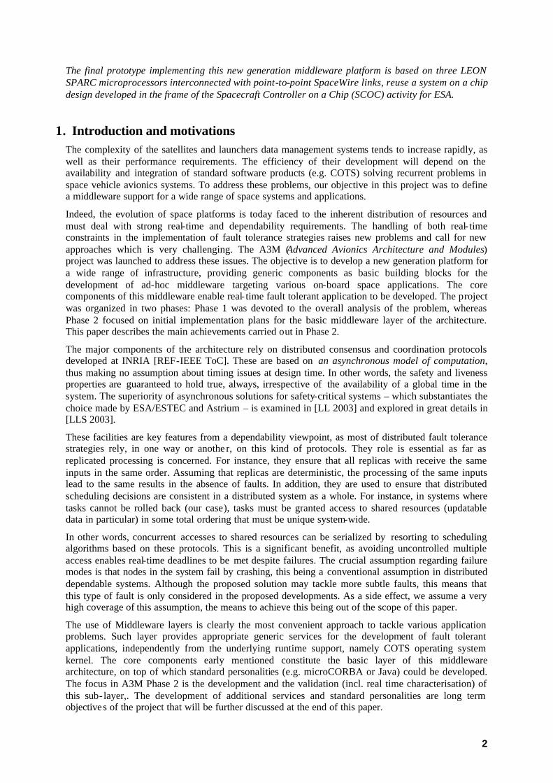
The complexity of the satellites and launchers data system tends to increase rapidly, as well as their performance requirements. The efficiency of their development will depend on the availability and integration of standard software products (e.g. COTS) solving recurrent problems in space vehicle avionics systems. To address these problems, our objective in this project was to define a middleware support for a wide range of space systems and applications. We primarily focused on the core functionalities that this middleware should provide, namely basic building blocks that are highly required for both dependability and real-time requirements.
During the first phase of the “Advanced Avionics Architecture and Modules” (A3M) activity (ESA TRP activity), solutions based on innovative algorithms from INRIA have been identified. The objective of the on-going second phase, to end in summer 2003, is to develop a basic middleware solving two application-centric problems and to evaluate the performance of the algorithms, on a standard space-borne computer platform. The two selected problems are “distributed consistent processing under active redundancy” and “distributed replicated data consistency, program serialization and program atomicity”.
The A3M basic middleware is decomposed into three main layers: The SpaceWire communication management layer, Uniform Consensus (UCS) and Uniform Coordination (UCN) protocols layer and the application level services layer. The SpaceWire communication management software, developed by Astrium, provides specific functionalities required by the UCS & UCN protocols. It also ensures that their implementation does not depend on a specific communication medium. The implementation of the UCS/UCN protocols layer, developed by Axlog as a library, has been verified through extensive and accurate testing under the Real Time OS simulator RTSim prior to the integration on the target platform. The main originality of this development was to fully develop (in C) the building block and simulate their behaviour, including in the presence of faults.
The highest layer of the middleware uses these protocols to provide the services solving the two selected problems to the application software. In particular, it relies on the customisation of the UCS and UCN protocols modules with application specific plug-in functions. Such type of solution may be applied to very different fields, from high performance distributed computing to satellite formation flying coordination.
2
The final prototype implementing this new generation middleware platform is based on three LEON SPARC microprocessors interconnected with point-to-point SpaceWire links, reuse a system on a chip design developed in the frame of the Spacecraft Controller on a Chip (SCOC) activity for ESA.
1. Introduction and motivations The complexity of the satellites and launchers data management systems tends to increase rapidly, as well as their performance requirements. The efficiency of their development will depend on the availability and integration of standard software products (e.g. COTS) solving recurrent problems in space vehicle avionics systems. To address these problems, our objective in this project was to define a middleware support for a wide range of space systems and applications.
Indeed, the evolution of space platforms is today faced to the inherent distribution of resources and must deal with strong real-time and dependability requirements. The handling of both real- time constraints in the implementation of fault tolerance strategies raises new problems and call for new approaches which is very challenging. The A3M (Advanced Avionics Architecture and Modules) project was launched to address these issues. The objective is to develop a new generation platform for a wide range of infrastructure, providing generic components as basic building blocks for the development of ad-hoc middleware targeting various on-board space applications. The core components of this middleware enable real- time fault tolerant application to be developed. The project was organized in two phases: Phase 1 was devoted to the overall analysis of the problem, whereas Phase 2 focused on initial implementation plans for the basic middleware layer of the architecture. This paper describes the main achievements carried out in Phase 2.
The major components of the architecture rely on distributed consensus and coordination protocols developed at INRIA [REF-IEEE ToC]. These are based on an asynchronous model of computation, thus making no assumption about timing issues at design time. In other words, the safety and liveness properties are guaranteed to hold true, always, irrespective of the availability of a global time in the system. The superiority of asynchronous solutions for safety-critical systems – which substantiates the choice made by ESA/ESTEC and Astrium – is examined in [LL 2003] and explored in great details in [LLS 2003].
These facilities are key features from a dependability viewpoint, as most of distributed fault tolerance strategies rely, in one way or anothe r, on this kind of protocols. They role is essential as far as replicated processing is concerned. For instance, they ensure that all replicas with receive the same inputs in the same order. Assuming that replicas are deterministic, the processing of the same inputs lead to the same results in the absence of faults. In addition, they are used to ensure that distributed scheduling decisions are consistent in a distributed system as a whole. For instance, in systems where tasks cannot be rolled back (our case), tasks must be granted access to shared resources (updatable data in particular) in some total ordering that must be unique system-wide.
In other words, concurrent accesses to shared resources can be serialized by resorting to scheduling algorithms based on these protocols. This is a significant benefit, as avoiding uncontrolled multiple access enables real-time deadlines to be met despite failures. The crucial assumption regarding failure modes is that nodes in the system fail by crashing, this being a conventional assumption in distributed dependable systems. Although the proposed solution may tackle more subtle faults, this means that this type of fault is only considered in the proposed developments. As a side effect, we assume a very high coverage of this assumption, the means to achieve this being out of the scope of this paper.
The use of Middleware layers is clearly the most convenient approach to tackle various application problems. Such layer provides appropriate generic services for the development of fault tolerant applications, independently from the underlying runtime support, namely COTS operating system kernel. The core components early mentioned constitute the basic layer of this middleware architecture, on top of which standard personalities (e.g. microCORBA or Java) could be developed. The focus in A3M Phase 2 is the development and the validation (incl. real time characterisation) of this sub- layer,. The development of additional services and standard personalities are long term objectives of the project that will be further discussed at the end of this paper.

3
The paper is organized as follows. Section 2 sketches the A3M architectural framework defined in Phase 1 that is the basis for the development carried out in Phase 2. In Section 3, we describe in some details the basic principles of the core components, namely UCS and UCN protocols and their variants developed in the project. In Section 4 we describe two key problems in space applications and their corresponding solutions based on the protocols described in Section 3. Section 5 focuses on the development strategy that was used and justifies its interest from a validation viewpoint. Section 6 addresses the intermediate and final platforms used for the implementation. Section 7 gives a brief overview of the current status of A3M Phase 2 and Section 8 draws early conclusions and the perspectives of this work.
2. Architectural framework The architectural framework of the middleware comprises a basic sub- layer implementing core components for the development of fault tolerant and real-time applications. This sub- layer was developed in A3M phase 2 on top of an off-the-shelf Real-Time Operating System kernel (RTOS) and a protocol stack specific to space platforms (COM), but no particular assumption is made on the selected candidates. The middleware itself has two facets. On top of the basic layer (facet 1) providing key algorithms, some additional services and personalities could be developed (facet 2) for targeting new problems and new application context. The work done until now was to develop the basic layer, i.e. the first facet of the A3M middleware. The overall architecture of the middleware is depicted in Figure 2-A.
The basic A3M middleware layer is built from two major protocols, Uniform Consensus (UCS) and Uniform Coordination (UCN), both relying on a Failure Detection Module (FDM). This layer is also populated with some specific services to tackle space related problems, for instance a Monitoring Process related to the distributed scheduling of concurrent processes and a Guardian Process related to the consistent updates of shared objects. This will be further discussed in Section 4.
(COTS) RTOS COM
A3MMiddleware
UCS UCN
FDM
Basic layer(core components)
Additional services and personalities
Figure 2/A: software architecture overview.
In order to allow the reuse of the basic components to solve different problems, several instances of each algorithm can execute in parallel. Each instance is customized with a “filter function” adapted to the problem.
3. Basic components and protocols
3.1. Uniform Consensus (UCS): basic principles
UCS is the name of the protocol that solves the Uniform Consensus (UC) problem, in the presence of processor crashes and arbitrarily variable delays. UCS comprises two algorithms, one which consists of a single round of message broadcasting, made accessible to application programs via a UCS

4
primitive, another which is called MiniSeq, that runs at a low level in the system (above the physical link protocol level). Both algorithms run in parallel.
Basically, UCS works as follows. Upon the occurrence of some event, every processor runs UCS by (1) broadcasting a message containing its Proposal to every other processor, (2) invoking MiniSeq. A Proposal may be anything (the name of a processor to be shut down, a list of pending requests that must be scheduled throughout the system, the name of a processor chosen as the “leader”, etc.). Upon termination, UCS delivers a Decision. A Decision must be (1) unique, (2) some initial Proposal. Uniformity requires that even those processors that are about to crash cannot Decide differently (than correct processors) before crashing. Note that, in practice, Consensus without the Uniformity property is useless.
The MiniSeq election algorithm, which is sequential, is run by processors according to their relative orderings (based upon their names, every processor having a known predecessor and a known successor). It is via MiniSeq that the Decision is made. MiniSeq uses an essential construct, which is a Failure Detector (FD). Every processor is equipped with an FD. An FD periodically broadcasts “I am alive” messages. When processor p has not been heard by processor q “in due time” (analytical formulae are used for setting timers), q puts p on its list of “suspects”. An interesting feature (F) of FDs is that it suffices to have just 1 correct processor never suspected by any other processor for solving the UC problem (even though lists of suspects are inconsistent).
In turn, every processor waits until some condition fires, and then, it broadcasts an FM-message, that contains the name of the processor proposed as the “winner”. That name is the name heard last from its predecessors. Hence, the condition is that every predecessor has been heard of (or is suspected). Thanks to (F), the “winner” is unique system-wide. It is the Proposal sent by the “winner” that is the Decision.
There is no a priori ordering of invocations of the UCS primitive (they may be truly concurrent). This above is referred to as the regular UCS invocation mode.
Another invocation mode of UCS, called the Rooted UCS invocation mode is available. R-UCS serves to make a particular kind of unique Decision, namely whether to abort or to commit a set of updates computed for data variables replicated across a number of processors. The major difference with the regular mode is that instead of having processor number 1 in charge of starting MiniSeq, it is the processor that actually runs the updating task – called the root processor – that is in charge of starting MiniSeq.
This serves to preserve data consistency despite processor failures.
3.2. Uniform Coordination (UCN): basic principles
UCS delivers some Decision, which can be any Proposal submitted initially. As explained further, there are applications such that some Proposal is “better” than some others. This raises a problem called UCN (Uniform Coordination). Basically, UCN is UCS, preceded with a round where every processor broadcasts a message containing a Contribution (to some calculus). At the end of that round, having collected all Contributions sent, some of them missing (crashed processors), every processor runs some computation (called “filters” see below). The result of that computation is a Proposal. UCS is then run. This is needed for the reason that “views” of received Contributions may be different for any two processors. Upon completion, one unique result is chosen as the Decision.
UCN may serve many purposes. One of the filters used in the A3M project is “majority voting”. Another is “aggregation of names, with some Boolean “and”/”or” functions”. The latter serves to do distributed scheduling.
5
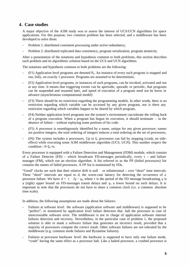
4. Case studies A major objective of the A3M study was to assess the interest of UCS/UCN algorithms for space applications. For this purpose, two common problem has been selected, and a middleware has been developed to solve them:
- Problem 1: distributed consistent processing under active redundancy,
- Problem 2: distributed replicated data consistency, program serialization, program atomicity.
After a presentation of the notations and hypothesis common to both problems, this section describes each problem and its algorithmic solution based on the UCS and UCN algorithms.
The notations and hypothesis common to both problems are the following:
- (F1) Application level programs are denoted Pk. An instance of every such program is mapped and run, fully, on exactly 1 processor. Programs are assumed to be deterministic.
- (F2) Application level programs, or instances of such programs, can be invoked, activated and run at any time. It means that triggering events can be aperiodic, sporadic or periodic, that programs can be suspended and resumed later, and speed of execution of a program need not be know in advance (asynchronous computational model)
- (F3) There should be no restriction regarding the programming models. In other words, there is no restriction regarding which variable can be accessed by any given program, nor is there any restriction regarding which variables happen to be shared by which program,
- (F4) Neither application level programs nor the system’s environment can tolerate the rolling back of a program execution. When a program has begun its execution, it should terminate – in the absence of failure – without replaying some portions of his code.
- (F5) A processor is unambiguously identified by a name, unique for any given processor; names are positive integers; the total ordering of integers induces a total ordering on the set of processors,
- (F6) The system includes n processors. Up to fm processors can fail by stopping (crash, no side-effect) while executing some A3M middleware algorithm (UCS, UCN). This number respect the condition : 0<fm<n.
Every processor is equipped with a Failure Detection and Management (FDM) module, which consists of a Failure Detector (FD) – which broadcasts FD-messages periodically, every τ – and failure manager (FM), which run an election algorithm. A list referred to as the FP (failed processors) list contains the names of failed processors. A FP list is maintained by FDs.
“Good” clocks are such that their relative drift is null or infinitesimal – over “short” time intervals. These “short” intervals are equal to d, the worst-case latency for detecting the occurrence of a processor failure. We have d = τ + 2γ − γ0, where τ is the period of the FD message broadcasting, γ is a (tight) upper bound on FD-messages transit delays and γ0 a lower bound on such delays. It is important to note that the processors do not have to share a common clock (i.e. a common absolute time scale).
In addition, the following assumptions are made about the failures:
- Failures at software level: the software (application software and middleware) is supposed to be “perfect”, or monitored by application level failure detectors that halt the processor in case of unrecoverable software error. The middleware is not in charge of application software internal failures detection and recovery. Nevertheless, in the particular case of problem 1, the proposed solution is able to mask a software failure that generates an incorrect result, provided that a majority of processors compute the correct result. Other software failures are not tolerated by the middleware (e.g. common mode failures and Byzantine failures).
- Failures at processor hardware level: the hardware is supposed to have only one failure mode, “crash” having the same effect as a processor halt. Like a halted processor, a crashed processor is
6
no longer able to send any message to the other processors. This implies that the processors have built- in failure detection mechanisms, which is generally the case with space computers.
- Failures at communication link or network level: the communication network is supposed to be reliable. For any message the maximum number of retransmissions needed for delivery is finite and bounded. A message can be lost, but not corrupted. The SpaceWire protocol ensures this assumption is valid concerning the demonstration platform. If the reliability of the SpaceWire error detection mechanism is not considered as acceptable for a real application, an higher level protocol may be added later. If a processor halts or crashes during the transmission of a message, the receiver ignores the partially received message. If the error is only transient, the subsequent messages are transmitted correctly.
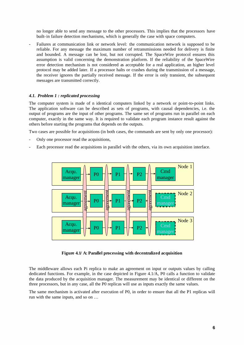
4.1. Problem 1 : replicated processing
The computer system is made of n identical computers linked by a network or point-to-point links. The application software can be described as sets of programs, with causal dependencies, i.e. the output of programs are the input of other programs. The same set of programs run in parallel on each computer, exactly in the same way. It is required to validate each program instance result against the others before starting the programs that depends on the outputs.
Two cases are possible for acquisitions (in both cases, the commands are sent by only one processor):
- Only one processor read the acquisitions,
- Each processor read the acquisitions in parallel with the others, via its own acquisition interface.
P0 P1 P2
Node 1
Node 2
Node 3
P0 P1 P2
P0 P1 P2
agre
emen
t
agre
emen
t
agre
emen
t
Acqu.manager
Cmdmanager
Acqu.manager
Acqu.manager
agre
emen
t
Cmdmanager
Cmdmanager
Figure 4.1/A: Parallel processing with decentralized acquisition
The middleware allows each Pi replica to make an agreement on input or outputs values by calling dedicated functions. For example, in the case depicted in Figure 4.1/A, P0 calls a function to validate the data produced by the acquisition manager. The measurement may be identical or different on the three processors, but in any case, all the P0 replicas will use as inputs exactly the same values.
The same mechanism is activated after execution of P0, in order to ensure that all the P1 replicas will run with the same inputs, and so on …
7
The use of this agreement services is not limited to a single sequential chain of applications: For example, if P0 and P0’ are running “in parallel” replicated on each processor, both can use the agreement service without having to be synchronized.
UCN with a “max filter” solves problem 1. Let UCN1 stand for this algorithmic solution.
Note that UCN is generic: It can be customized for specific application dependability problems with the use of various filtering or decision functions. Besides the two filters (max and total ordering) retained for A3M problem 1 and problem 2, we could have other specific filter functions can be developed in order to solve problems possibly very different from the ones selected for A3M phase 2.
UCN1 is invoked by the Pk,x’s, whenever needed. In other words, application- level programmers can insert calls to UCN1 in their code wherever this seems appropriate. The consistency of these middleware calls within application programs must be verified beforehand during the development process of the application software.
Max filter: When computation conditions are met (UCN phase 1), eve ry processor has a vector V of up to n entries, each corresponding to a Contribution. Let V_diff be the sub-vector of V that contains all differing Contributions, with exactly 1 entry per differing Contribution.
For every entry of V_diff, one computes the number of occurrences in V of the corresponding Contribution. Result is the Contribution that has the highest number of occurrences (max). When more than one Contribution reaches max, choice of which one is selected as Result is free i.e. any election algorithm can be used.
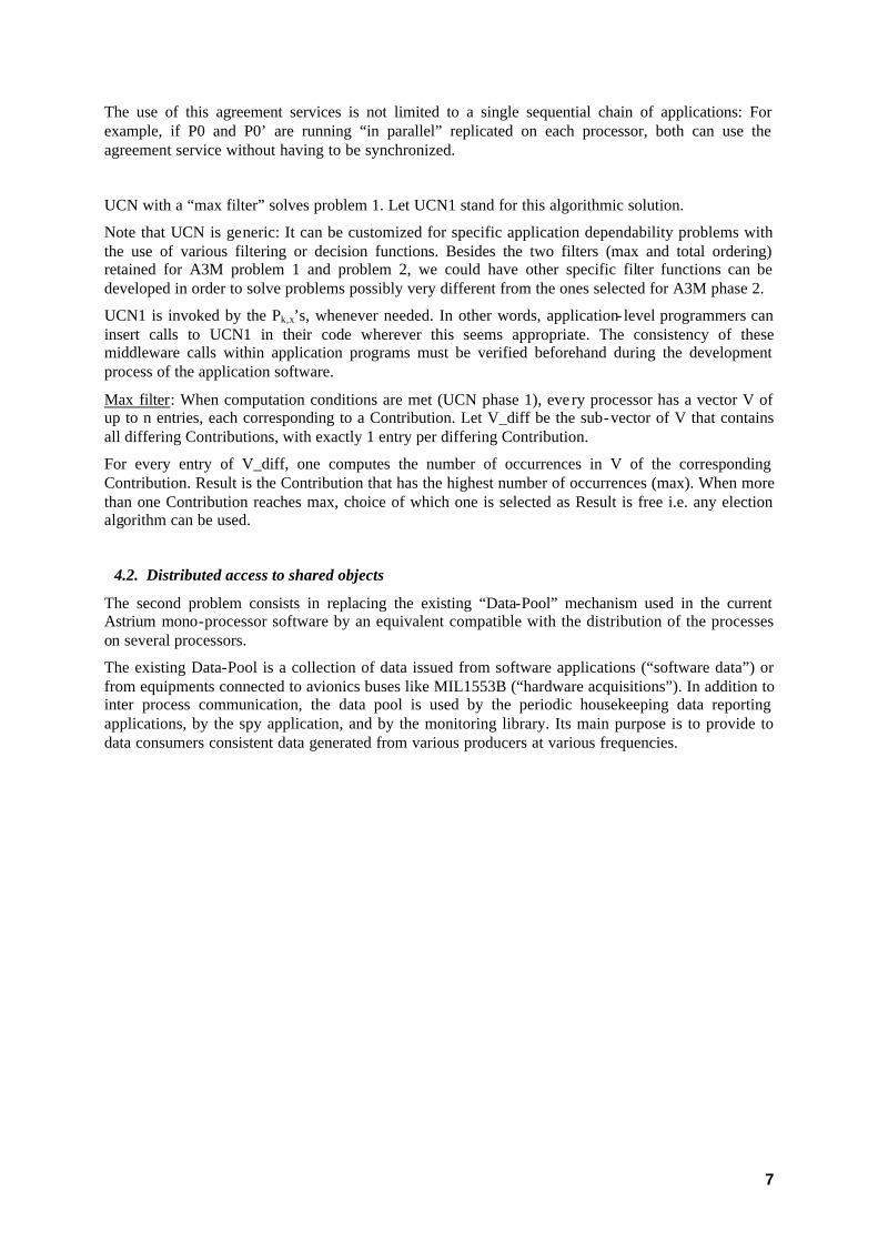
4.2. Distributed access to shared objects
The second problem consists in replacing the existing “Data-Pool” mechanism used in the current Astrium mono-processor software by an equivalent compatible with the distribution of the processes on several processors.
The existing Data-Pool is a collection of data issued from software applications (“software data”) or from equipments connected to avionics buses like MIL1553B (“hardware acquisitions”). In addition to inter process communication, the data pool is used by the periodic housekeeping data reporting applications, by the spy application, and by the monitoring library. Its main purpose is to provide to data consumers consistent data generated from various producers at various frequencies.
8
P1
P2Node 1
Node 2
Node 3
P3
P4
P7
P6
Dis
trib
uted
«da
ta-p
ool»
P5
Figure 4.2/A: Distributed Data-Pool mechanism
The application tasks use middleware services to ensure the consistency of operations performed on data pool variables sets. The programming model selected for these services is based on the notion of “critical section”. The critical section of an application shall be considered as atomic by all the other applications with respect to the data-pool contents. There is no limitation on the number of read and write accesses performed on data-pool variables in a single critical section. Obviously, the duration of the critical sections should be kept as small as possible, in order to avoid to degrade the overall system performance.
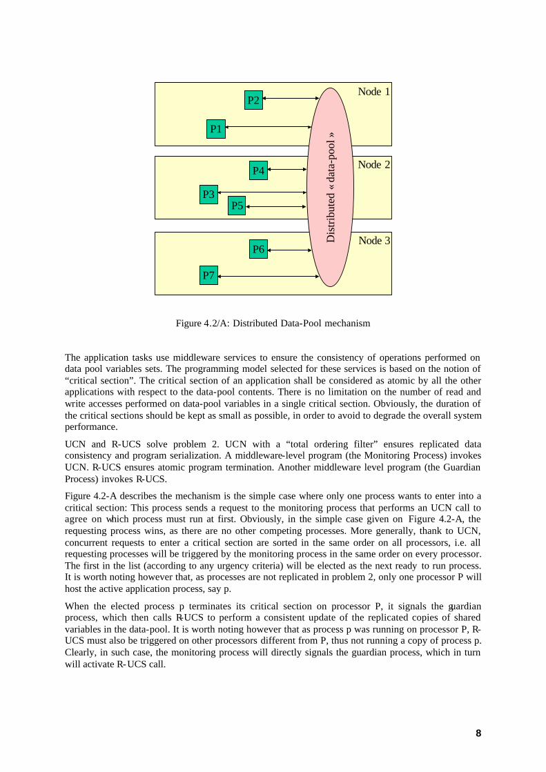
UCN and R-UCS solve problem 2. UCN with a “total ordering filter” ensures replicated data consistency and program serialization. A middleware-level program (the Monitoring Process) invokes UCN. R-UCS ensures atomic program termination. Another middleware level program (the Guardian Process) invokes R-UCS.
Figure 4.2-A describes the mechanism is the simple case where only one process wants to enter into a critical section: This process sends a request to the monitoring process that performs an UCN call to agree on which process must run at first. Obviously, in the simple case given on Figure 4.2-A, the requesting process wins, as there are no other competing processes. More generally, thank to UCN, concurrent requests to enter a critical section are sorted in the same order on all processors, i.e. all requesting processes will be triggered by the monitoring process in the same order on every processor. The first in the list (according to any urgency criteria) will be elected as the next ready to run process. It is worth noting however that, as processes are not replicated in problem 2, only one processor P will host the active application process, say p.
When the elected process p terminates its critical section on processor P, it signals the guardian process, which then calls R-UCS to perform a consistent update of the replicated copies of shared variables in the data-pool. It is worth noting however that as process p was running on processor P, R-UCS must also be triggered on other processors different from P, thus not running a copy of process p. Clearly, in such case, the monitoring process will directly signals the guardian process, which in turn will activate R-UCS call.
9
Processor 1 Processor 2 Processor3
Begin
End
UCN2
Appl. 1process
Monitoring.Process
R-UCS
Monitoring.Process
UCN2
R-UCS
Guardian.Process
Guardian.Process
Monitoring.Process
UCN2
R-UCS
A, B A, B A, B
Data-pool replicas (one on each processor)
Read&
Write
Read Write Write
Guardian.Process
Read(*)
Read(*)
(*) the value will be used in case of processor 1 failure during R-UCS
Figure 4.2-A: Problem 2 algorithmic solution
5. Development and validation 5.1. Overall approach
The main originality of the development was to fully develop (in C language) the building block and validate their behaviour under simulation, includ ing in the presence of faults. This approach was possible thanks to RTSim, a real-time executive simulator.
A distributed framework enabled us to execute complex scenarios, including the creation of an architecture, the setting of a network model, various ways of algorithms stimulation, and temporal and logic fault injection mechanism.
5.2. RTSim Overview
RTSim is a product developed by AXLOG. Its aim is to enable the development, in host-based environment, of real- time software based on various real- time executive of the market (pSOS+m, VXWORKS, Chorus, ARINC653, …), and their running under simulation without any target hardware.
By creating nodes, which are the representation of a hardware module running a real-time executive, RTSim could manage simulated architecture from a tiny application running on a single-target system to complex multi-node architecture running a complex distributed application.

10
Moreover, this tool offers advanced debugging, monitoring, controlling and instrumentation facilities over your application.
Eventually, RTSim has its own internal simulation clock, which enables us to replay a given simulation indefinitely with the same behaviour, permitting a fast and reliable way to track defects.
5.3. Development and simulation environment
The first phase consists in the development of the building block. This was done following a test-driven development approach (TDD), i.e. that each function described by the application programming interface (API) are unitary tested. Moreover unit tests are being written previously to the code.
The main advantages of this approach are:
- a use of the API in tests as in the future user code, giving possible refactoring enhancements before effective coding;
- a test database provides indicators on the current developme nt velocity;
- regression tests could be passed easily in case of future implementation changes.
The second phase is the building block integration in the distributed simulation framework to pass functional validation. The architecture of this framework could be represented by the figure 5.3-A.
It consists in the building of a multi-node architecture composed of a set of Processor under Test (PuT) representing the target hosting the module to be validated and a special node, the Processor of Test (PoT), responsible for the network simulation, the scenarios execution and reporting. All these nodes are connected to a perfect link.
Let us describe more precisely these nodes.
Figure 5.3-A: Architecture of the distributed framework
PoT: This node is in charge of stimulating and controlling the distributed applications, simulating the network, and archiving all actions taken by the system. Figure 5.3-B gives a better view of it.

11
Figure 5.3-B: Architecture of a PoT
We could see that the architecture is composed of three parts. - the network simulation service: its aim is to postpone the effective release of a message according
to the model of the network used. To achieve this task, it takes a network model as parameter during this initialisation phase. Then, each time an applicative message is being sent by a PuT, this message are redirected to the PoT, this module computes the delay of the message, eventually, the message is released when the delay expires, and is sent to the destination PuT.
- The stimulator: its goal is to run a scenario of execution of the distributed system. A scenario is composed of an initialisation phase where the parameters of the architecture are being set, then a stimulation phase where actions are being taken on PuT. These actions are one-shot algorithm activation, arrival law algorithm activation, temporal and logic failure injection,…
- The archiver, which is responsible for the tracing of all events that occurs on a PuT and gives a human readable representation of the simulation result.
PuT: This part hosts the algorithm module, a synthetic applicative workload, and a network service. Figure 5.3-C gives a better view of it.
Figure 5.3-C: Architecture of a PuT
We can see that the architecture is composed of three parts:
- a network service that is in charge of transmitting and receiving messages. It also hosts three parts:
o NetInterface represents the COM interface available for the UCS/UCN module and NetControl the one for the exchange of service message. Messages will be typed to be interpreted differently in the underlying NetProbed layer.
12
o NetProbed which is an instrumentation layer that makes the distinction between the different messages. This layer is also responsible for the failure of a processor by inhibiting the send and receive functionalities.
o NetPhysical which constitutes the physical part and redirects the messages to the PoT.
- a UCS/UCN module that hosts the components to be validated. - a synthetic applicative workload that triggers the UCS/UCN module according to the
stimulation orders received from the PoT. A result message is sent to the archiver of the PoT to be logged.
5.4. Test scenarios
The final step is the writing of the database scenarios to have a 100% of coverage at the building block level. Due to the asynchronous nature of the algorithm, time has no effect on safety and liveliness properties of the algorithms, thus failure occurrence is the only parameter we have to handle.
Moreover, the algorithms could be described on each processor by a state-machine diagram. All we have to do is placing the failure occurrences in these state diagrams and derive the scenarios.
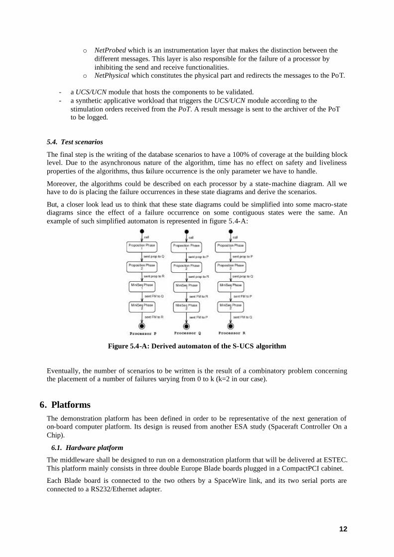
But, a closer look lead us to think that these state diagrams could be simplified into some macro-state diagrams since the effect of a failure occurrence on some contiguous states were the same. An example of such simplified automaton is represented in figure 5.4-A:
Figure 5.4-A: Derived automaton of the S-UCS algorithm
Eventually, the number of scenarios to be written is the result of a combinatory problem concerning the placement of a number of failures varying from 0 to k (k=2 in our case).
6. Platforms The demonstration platform has been defined in order to be representative of the next generation of on-board computer platform. Its design is reused from another ESA study (Spaceraft Controller On a Chip).
6.1. Hardware platform
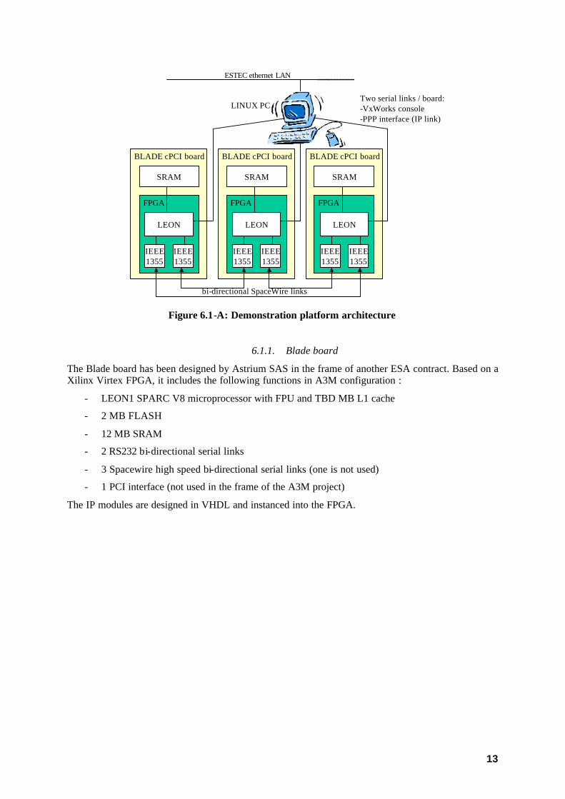
The middleware shall be designed to run on a demonstration platform that will be delivered at ESTEC. This platform mainly consists in three double Europe Blade boards plugged in a CompactPCI cabinet.
Each Blade board is connected to the two others by a SpaceWire link, and its two serial ports are connected to a RS232/Ethernet adapter.
13
SRAM
FPGA
LEON
IEEE1355
IEEE1355
BLADE cPCI board
SRAM
FPGA
LEON
IEEE1355
IEEE1355
BLADE cPCI board
SRAM
FPGA
LEON
IEEE1355
IEEE1355
BLADE cPCI board
ESTEC ethernet LAN
bi-directional SpaceWire links
Two serial links / board:-VxWorks console-PPP interface (IP link)
LINUX PC
Figure 6.1-A: Demonstration platform architecture
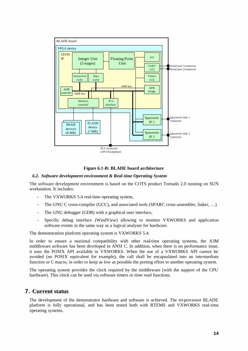
6.1.1. Blade board
The Blade board has been designed by Astrium SAS in the frame of another ESA contract. Based on a Xilinx Virtex FPGA, it includes the following functions in A3M configuration :
- LEON1 SPARC V8 microprocessor with FPU and TBD MB L1 cache
- 2 MB FLASH
- 12 MB SRAM
- 2 RS232 bi-directional serial links
- 3 Spacewire high speed bi-directional serial links (one is not used)
- 1 PCI interface (not used in the frame of the A3M project)
The IP modules are designed in VHDL and instanced into the FPGA.
14
Integer Unit(5 stages)
Instructioncache
Datacache
Floating-PointUnit
AHBcontroler
Memorycontroler
PCIinterface
APBbridge
I/O
UART(x2)
Timers(x2)
AHB bus
APB bus
LEONIP
SRAMdevices(8 MB)
FLASHdevice(? MB)
BLADE board
PCI connector(cPCI backplane)
SpacewireIP 2
SpacewireIP 1
Spacewire link 2connector
Spacewire link 1connector
Serial port 1connectorSerial port 2connector
FPGA device
SRAMdevices(8 MB)
Figure 6.1-B: BLADE board architecture
6.2. Software development environment & Real-time Operating System
The software development environment is based on the COTS product Tornado 2.0 running on SUN workstation. It includes:
- The VXWORKS 5.4 real- time operating system,
- The GNU C cross-compiler (GCC), and associated tools (SPARC cross-assembler, linker, …)
- The GNU debugger (GDB) with a graphical user interface,
- Specific debug interface (WindView) allowing to monitor VXWORKS and application software events in the same way as a logical analyser for hardware.
The demonstration platform operating system is VXWORKS 5.4.
In order to ensure a maximal compatibility with other real-time operating systems, the A3M middleware software has been developed in ANSI C. In addition, when there is no performance issue, it uses the POSIX API available in VXWORKS. When the use of a VXWORKS API cannot be avoided (no POSIX equivalent for example), the call shall be encapsulated into an intermediate function or C macro, in order to keep as low as possible the porting effort to another operating system.
The operating system provides the clock required by the middleware (with the support of the CPU hardware). This clock can be used via software timers or time read functions.
7. Current status The development of the demonstrator hardware and software is achieved. The tri-processor BLADE platform is fully operational, and has been tested both with RTEMS and VXWORKS real- time operating systems.

15
The SpaceWire communication software has been tested, and its performance measured. The raw performance of the hardware is pretty good (30 Mbits/s from memory to memory with a bit rate equal to 40 Mbit/s which correspond to 99.5% of the usable rate), but the software mechanisms required at communication level by the middleware algorithms decrease the useful data rate. Figure 7-A presents the duration of the synchronous packet transmit for different packets sizes and bit rates.
SpaceWire communication performance
-
200
400
600
800
1 000
1 200
0 500 1000 1500
Packet size (bytes)
mic
ro-s
econ
ds p
er c
all
80 Mbit/s40 Mbit/s
Figure 6.2-A: SpaceWire communication services performance
The middleware basic layer (UCS/UCN/FDM) has been extensively tested on the RTSIM simulator, including the verification of their properties. The functional tests of the two middleware application level services have been achieved. Very few functional problem has been found on the demonstration platform, thank to the simulation campaign.
The final middleware evaluation tests are currently under development, with the objective to make accurate performance measurement that will be correlated with theoretical performance predictions.
8. Conclusion and perspectives The aim of the A3M project is to investigate and develop a new generation middleware for space applications. The distributed nature of the space platforms, the real- time requirements of the on-board applications together with stringent dependability constraints call for novel architectural frameworks and core services. The full picture also includes development processes and tools at various stages of the design and the implementation of the system. As far as real- time constraints must be obeyed, a deep analysis of the application organization, the shared resources and timing behaviour must be done a priori [REF-Phase1-GLL-reports]. This entails focussing on an appropriate design where application tasks are clearly identified together with their shared variables, and thus making visible at early stage their possible critical sections, this leading to a full description of the application concurrency and timing constraints.
The work carried out in A3M Phase 2 led to the development of the basic sub- layer of the middleware. The core components rely on UCS and UCN variants devoted to solving conventional problems in space applications, ensuring fault-tolerance and real-time behaviour in a distributed environment.
16
This work is the starting point for the development of middleware-based platforms for space applications. It demonstrates the benefits of advanced research results in this context and calls for further development of middleware-based systems for dependable modular avionics systems. It also shows the significant interest of simulation-based approaches for the development of basic middleware services and their validation, including in the presence of faults using fault injection techniques. However, this work must be consolidated with further implementation characterisation, as well as extended with new services (e.g. plug- in) and standard elements to comply with application-specific requirements and generic interoperability/application development needs, respectively. The underlying generic philosophy of this work must be illustrated in future phases of the project, possibly with other industrial partners and targeting different application context. The results obtained are very promising and the development of additional middleware capabilities should be very attractive for the space industry at large.
Several development axis have been identified:
1) Improvement of the middleware software implementation in order to increase the performance. The preliminary results prove that a closer coupling of the communication with the basic layers would improve the performance, by eliminating intermediate software mechanisms.
2) ECSS Standardisation for space should be then derived.
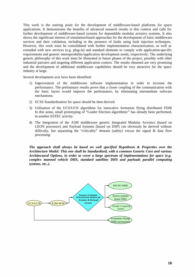
3) Utilisation of the UCS/UCN algorithms for innovative formation flying distributed FDIR In this sense, small prototyping of “Leader Election algorithmic” has already been performed, in another ESTEC activity.
4) The Integration of the A3M middleware generic Integrated Modular Avionics (based on LEON processor) and Payload Systems (based on DSP) can obviously be derived without difficulty, but separating the “criticality” domain (safety) versus the signal & data flow processing.
The approach shall always be based on well specified Hypothesis & Properties over the Architecture Model: This one shall be Standardized, with a common Generic Core and various Architectural Options, in order to cover a large spectrum of implementations for space (e.g. complex manned vehicle DHS, standard satellites DHS and payloads parallel computing systems, etc..).
UCS/UCN A3M M/W
Formation FlyingFDIR mechanisms
ISS NG DMS
Aurora systemsfuture DHS
Generic EvolutionINTEGRATED MODULAR
Avionics & PayloadSystem
Parallel Computing System
17
9. References
[IEEE ToC] J.-F. Hermant, G. Le Lann, « Fast Asynchronous Uniform Consensus in Real-Time Distributed Systems », IEEE Transactions on Computers, vol. 51(8), August 2002, pp. 931-944.
[LL 2003] G. Le Lann, “Asynchrony and Real-Time Dependable Computing”, Proceedings of the 8th IEEE Intl. Workshop on Object-Oriented Real-Time Dependable Systems (WORDS), January 2003, Guadalajara, Mexico (to appear).
[LLS 2003] G. Le Lann, U. Schmid, « How to Maximize Computing Systems Coverage », submitted for publication, April 2003, INRIA Research Report in preparation.