
Towards an Integrated Proposal for Interactive Systems Design Based on TLIM and ICO
26
Towards an integrated proposal for Interactive Systems design based on TLIM and ICO Philippe Palanque 1,3 , Fabio Paterno 2 , Rémi Bastide 3 , Menica Mezzanotte 2 1 CENA 7 avenue Edouard Belin 31055 Toulouse, France Tel: +33 62 25 95 91 [email protected] 2 CNUCE - CNR, 36, via Santa Maria, 56128 PISA, Italy Tel: +39 50 59 32 89 [email protected] 3 LIS - IHM Université Toulouse I 31042 Toulouse, France Tel: +33 61 63 35 88 [email protected] Abstract The importance of applying formal methods in the design and development process of Interactive Systems is increasingly recognised. However it is still an open issue the identification of systematic methods able to support designers and developers in specifying and demonstrating properties of user interfaces. TLIM and ICO are two formal methods which have been used for this purpose with interesting results. They address similar concepts but also have different features which allow us to consider useful their integrated use to obtain synergistic and complementary results. In this paper we show their application to some examples in order to discuss similarities and differences and we outline a proposal for their integrated use. 1. Introduction In the domain of interactive systems, there is a lack of structured methods which can drive the work of designers and developers especially for applications which require sophisticated interaction techniques. We think that a valid answer to these problems can be found only by expressing both tasks and system models in a formal way. This is precisely the aim of both TLIM and MICO methods that have already been introduced in [31, 28]. The purpose of this paper is twofold: • to compare the two methods (TLIM and MICO) for the design, specification, verification, development and evaluation of Interactive Systems both based on the use of formal techniques; • to identify elements useful for a proposal which takes features from the two previous methods and indicates a new method, with related tools and techniques, for improving the design and development of user interfaces. We believe that the goal to obtain a single notation powerful enough to express all the relevant aspects in user interface design will not find a successful result because such a notation should be very complicated to develop and to use. This complication in most cases would be useless as usually designers would be interested only in a specific subset of its functionality as they often need to focus only on some aspects which depend on their current goals. Thus we think that a more successful approach is to identify a set of interesting notations and to indicate clearly when one is better than the
Transcript of Towards an Integrated Proposal for Interactive Systems Design Based on TLIM and ICO
Towards an integrated proposal for Interactive Systemsdesign based on TLIM and ICO
Philippe Palanque1,3, Fabio Paterno2, Rémi Bastide3, Menica Mezzanotte2
1
CENA7 avenue Edouard Belin31055 Toulouse, France
Tel: +33 62 25 95 [email protected]
2 CNUCE - CNR,
36, via Santa Maria,56128 PISA, Italy
Tel: +39 50 59 32 [email protected]
3
LIS - IHMUniversité Toulouse I
31042 Toulouse, FranceTel: +33 61 63 35 88
Abstract The importance of applying formal methods in the design anddevelopment process of Interactive Systems is increasingly recognised.However it is still an open issue the identification of systematic methods able tosupport designers and developers in specifying and demonstrating properties ofuser interfaces. TLIM and ICO are two formal methods which have been usedfor this purpose with interesting results. They address similar concepts but alsohave different features which allow us to consider useful their integrated use toobtain synergistic and complementary results. In this paper we show theirapplication to some examples in order to discuss similarities and differencesand we outline a proposal for their integrated use.
1. Introduction
In the domain of interactive systems, there is a lack of structured methods which candrive the work of designers and developers especially for applications which requiresophisticated interaction techniques. We think that a valid answer to these problemscan be found only by expressing both tasks and system models in a formal way. Thisis precisely the aim of both TLIM and MICO methods that have already beenintroduced in [31, 28].The purpose of this paper is twofold:• to compare the two methods (TLIM and MICO) for the design, specification,
verification, development and evaluation of Interactive Systems both based on theuse of formal techniques;
• to identify elements useful for a proposal which takes features from the twoprevious methods and indicates a new method, with related tools and techniques,for improving the design and development of user interfaces.
We believe that the goal to obtain a single notation powerful enough to express all therelevant aspects in user interface design will not find a successful result because sucha notation should be very complicated to develop and to use. This complication inmost cases would be useless as usually designers would be interested only in a specificsubset of its functionality as they often need to focus only on some aspects whichdepend on their current goals. Thus we think that a more successful approach is toidentify a set of interesting notations and to indicate clearly when one is better than the
others and how concepts from a notation can be mapped onto concepts of anothernotation.Two aspects are important in the specification of Interactive Systems: parallelism andtemporal ordering among actions. Thus we will consider two notations based on theseconcepts: Petri Nets [29] and LOTOS [14] and the goal of this work is to evaluate twomethods based on them, to check whether they are both useful, or complementary, andcan be used with synergistic effects.The global goal of this research work is to be able to both give precise descriptions ofthe relevant aspects in the design of Interactive Systems and provide the possibilit y toreason about properties which are important in the design, development andevaluation of user interfaces.
2. Related work
UAN [12] is an example of successful notation which has been used to describe bothtasks and external behaviour of corresponding user interfaces. We aim to describe alsothe software component controlli ng the external user interface in order to providesupport to both developers and designers.Sutcli ffe and Farady [36] have developed an interesting approach which starts fromthe result of task analysis and provides useful suggestions for the design of multimediauser interfaces taking into account aspects such as the type of information to bepresented, the communicative goal and the resources available. However they do notprovide precise specifications of the design rules and the resulting specification.Gray and Johnson [11] have discussed the requirements for the next generation of userinterface specification languages. They argue that many existing approaches cannoteasily be used to capture the temporal properties that characterise interaction withdistributed systems. They indicate Branching Time Temporal Logic, XUAN and PetriNets as examples of notations which avoid this limitation and recognise the need todevelop a hybrid notation from the best features of several existing formalisms.The idea of an integrated use of LOTOS and Petri Nets has already been recogniseduseful. Sisto and Valenzano [38] have defined how to map Petri nets with inhibitorarcs into basic LOTOS specification preserving strong bisimulation equivalence.However, both basic LOTOS and Petri nets with inhibitor arcs have an expressivepower too low for an easy modelli ng of interactive systems. Another approach fortranslating Full LOTOS specifications into Petri nets can be found in [15].Instead of comparing formalisms in general terms, this paper compares two methodsaddressing the specific requirements of interactive systems design. These methods arebased on higher level models which are Full LOTOS and Interactive CooperativeObjects (a formalism based on Petri nets and objects) respectively.
3. Basic concepts for formal design of interactive systems
Many studies (such as [6] p. 404) have highlighted that the design of InteractiveSystems depends on three models:• user model, a specification to describe the user behaviour and characteristics,
mainly from a cognitive point of view;
• tasks model, the abstract description of how the user can achieve some desiredstate modifications which are associated with his/her goals;
• system model, the identification of the basic architectural components whichmodel the implementation.
In all these three models the key elements are:• requirements, which can be considered as specific properties that have to be
satisfied; for example temporal requirements that express temporal behaviour andconstraints where time is considered from a quantitative point of view;
• notation, the formalism used to describe the different models. These notations canbe either formal or informal but as far as system model is concerned, we considernotations developed in the software engineering field ;
• tools, whether there exit automatic support for the building of both thespecification and the implementation and for further processing such asverification, simulation and execution of the specification;
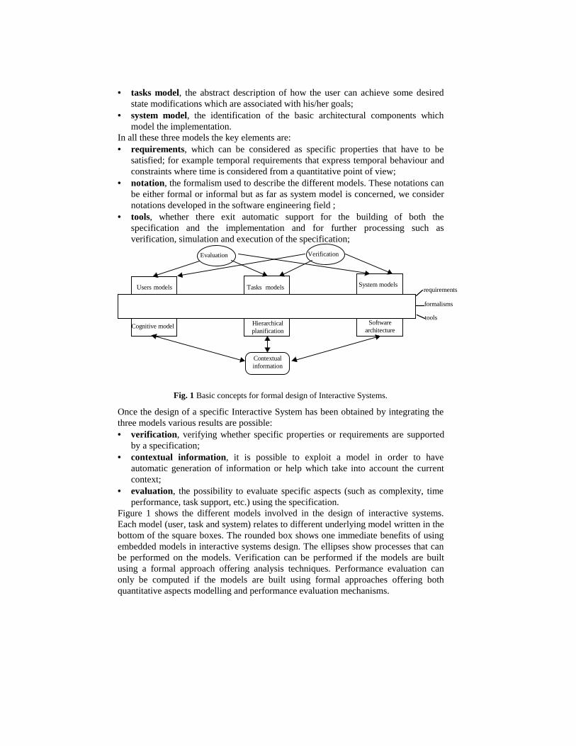
Evaluation Verification
Contextualinformation
System modelsTasksUsers models models
tools
formalisms
requirements
Cognitive model Hierarchicalplanification
Softwarearchitecture
Fig. 1 Basic concepts for formal design of Interactive Systems.
Once the design of a specific Interactive System has been obtained by integrating thethree models various results are possible:• verification, verifying whether specific properties or requirements are supported
by a specification;• contextual information, it is possible to exploit a model in order to have
automatic generation of information or help which take into account the currentcontext;
• evaluation, the possibilit y to evaluate specific aspects (such as complexity, timeperformance, task support, etc.) using the specification.
Figure 1 shows the different models involved in the design of interactive systems.Each model (user, task and system) relates to different underlying model written in thebottom of the square boxes. The rounded box shows one immediate benefits of usingembedded models in interactive systems design. The elli pses show processes that canbe performed on the models. Verification can be performed if the models are builtusing a formal approach offering analysis techniques. Performance evaluation canonly be computed if the models are built using formal approaches offering bothquantitative aspects modelling and performance evaluation mechanisms.
The three layers (requirements, formalisms and tools) are shown in an horizontal barstating that they are meaningful for the three different models.
4. The design process
In this paragraph we give a short outline of the methods which we consider and wediscuss both of them with respect to the issues indicated in the previous section.In the TLIM method the tasks are identified at the beginning together with theirconstraints which are described by LOTOS operators. Tasks are described in ahierarchical way using LOTOS operators to indicate their temporal relationships. Foreach task it is possible to provide tables with objects and actions. Next we have toidentify how tasks are associated with software components. The transformation isdriven by the tasks relationships and we obtain an interactor-based description of asystem which comply the task constraints. This architectural description can begraphically described and it can be translated into a corresponding LOTOSexpression. The LOTOS specification can be used as the model to check automaticallyproperties expressed by Action-based temporal Logic. The result of the verification isuseful to evaluate the design performed. Depending on the result of the evaluationboth the task specification and the formal specification of the software architecturecan be modified. Once a satisfying design has been obtained the prototyping of theimplementation is almost a mechanical exercise because we developed an interactor-based toolkit which provides software objects with the same architecture as the objectsused to structure the specification.In the MICO method we can start the design process using either a preliminary taskmodel or a preliminary system one. This preliminary task (respectively system) modelis then used in order to build the system (respectively task) model. Each time a modelis built , verification is performed on it in order to ensure its soundness. Then the taskand system models are evaluated in order to check the conformance of the systemmodel with respect to the task model. This is done by automatically building a singlemodel by merging both tasks and system models. The analysis of this model willdetermine whether or not the models are compatible (see [24] for a completedescription of the process). If the models are compatible (all the tasks are supportedby the system model) some performance evaluation (such as time to achieve a task) iscomputed. This cycle is performed until the result of the performance evaluation isgood enough. This only describes how the different stages of the MICO refer to thedesign process (see for a complete description [23]). The precise description of howthe system models are built according to the three classical layers (Presentation,Dialogue and Functional Core) can be found in [28].One relevant difference is that in TLIM the task model is used as an abstractspecification which is used to model the system specification, while in MICO they areconsidered at the same abstraction level and the designer can start to work with one ofthem without any difference.
4.1 The Formalism
In TLIM there is a mix of formal notation and informal graphical representations. TheLOTOS notation is used to perform specification of the three main elements (user,
task and system). It is oriented to express temporal ordering of actions that aconcurrent system can perform. Often an informal graphical representation is used fordescribing the software architecture in a more immediate way with respect to theLOTOS specification (we have boxes corresponding to each single LOTOS processand arrows associated with the synchronisation gates). Requirements and propertiesare expressed using Action-based temporal logic [7] which is a branching timetemporal logic which allows designers to reason about actions that the entityconsidered can perform.The MICO method heavily relies on one formalism: the Interactive CooperativeObjects. This formalism is based on both Petri nets and the object oriented approach.This formalism is used for the description of tasks, users and system models. Petri netsconcepts are used in order to describe the dynamics in the models while object-oriented ones are used for structuring concerns. The object oriented approach providesa set of other notations such as inheritance trees, use relationship diagrams that areused in order to describe the software architecture and to structure the models. At themoment we have no notations in order to describe properties or requirements. We planto use temporal logic to describe them and to use work that has already been done inthe Petri net community in order to prove that the Petri nets models verify theproperties expressed in temporal logic.
4.2 Task models
In TLIM the task specification is used to describe the set of possible user tasks andtheir temporal constraints. LOTOS operators (such as interleaving, enabling,disabling, synchronisation) are used to describe these constraints. In the taskspecification only constraints related to the task level are expressed withoutconsidering possible constraints introduced by the user interface implementation. Inthe specification there is a hierarchical decomposition of the possible tasks. It ispossible to give further information about each task indicating what the relatedsemantic objects and actions are.In MICO task models are used in order to describe user's action on a system. Thoseactions are structured according to goals. A goal is a high level abstraction of task. Fora given goal there are several possible task models describing the possibiliti es toachieve this goal. In a task model we describe the sequences of actions that the userhas to perform on the system in order to achieve his/her goal. Task models aredescribed using the ICO formalism. This formalism based on Petri nets and objectsallows to describe temporal relationship between actions and the synchronisation ofseveral flow of control usually called multi threading which is frequently encounteredin interactive systems. Time extensions of Petri nets are added to the task description.This is used during the performance evaluation phase when it comes to find out thecomplexity of a task.
4.3 Software architecture
In TLIM software architectures are modelled following the interactor model. It is anabstract model to describe software objects which have to interact with users. It ischaracterised as an entity able to support a bidirectional information flow from the

user side to the application side and vice versa. Its communication with the outside isstructured by six types of channels which are classified depending on they are used forinformation communication or control events (triggers) or if they are used to receive(or to send) information from (to) the user or the application. On the implementationside this model has been implemented in an object-oriented programming language insuch a way to maintain the properties of the abstract model.In MICO we address software architecture in two different ways.The first one is to describe what a basic component of the system is: the behaviour, thedata structure and the services. For services and data structure we use the objectoriented constructs while for the behaviour we use Petri nets.The second way is to describe how the components cooperate. This is done using aformal client server protocol expressed in Petri nets. This protocol is used for thecooperation between objects in the system model but also between system model andthe other models (user and task). The resulting software architecture can be directlyimplemented using any classical object-oriented environment.
4.4 Verification
In the MICO method we verify properties on the quality of the design of the models.We address properties such as absence of deadlocks, reinitialisabilit y, computation ofreachable states. This verification is done on system, tasks and user specifications.According to the software architecture, this verification can be done either on aprecise component in order to verify its soundness (what we call unitary verification)or on a set of components cooperating together (what we call cooperationverification). Unitary verification is performed using results available from the Petrinet theory while cooperation verification is done using results on the formal clientserver protocol. Algorithms for the verification of properties are available and it isthus straightforward to add a verification module in a design environment. A full studyabout both unitary and cooperation verification can be found in [24]. Anotherverification can be performed using performance analysis techniques. Indeed,undesirable behaviours of the system can be found by looking at the performanceanalysis results.In TLIM verification is performed by general tools for model checking: the LOTOSspecification of the Interactive System is automatically translated into a correspondingfinite state transition system. Next ACTL properties can be automatically checkedagainst this model and the tools can indicate whether or not they are verified and inthe negative case give information about why they are not verified. ACTL has beenused to prove:• usability properties (such as continuous feedback, visibility, ...);• task-related properties (such as task reachabilit y, possibilit y to perform a task at
any state, task equivalence);• safety properties (whether some bad behaviour can happen).One limitation in this approach is that there are LOTOS expressions which correspondto transition systems with an infinite number of states thus the model checkingapproach needs to be replaced with new techniques which are being developed andwhich, at this time, are able to provide answers only in a subset of cases. A discussion
about when applying these types of techniques for verifying user interface propertiescan be found in [19]
4.5 Time
Temporal aspects are fully incorporated in the MICO methodology. Indeed, the use ofPetri net for describing the behaviour of objects in models allows us to describequalitative temporal relationships between actions. These temporal relationships canbe before, after, meanwhile as well as concurrent behaviour. Moreover, it is possibleto use temporal extensions of Petri nets in order to describe quantitative temporalrelationships both at a static and a stochastic level. Static temporal aspects allowdescriptions such as this will happen in 10 seconds or this will l ong 1 minute.Stochastic temporal aspect allow us to model the stochastic behaviour of the userwhen interaction is concerned. For example it is possible to use probabili stic laws inorder to describe the time that will be elapsed before the user presses a button after amessage appears. The mathematical foundations of Petri nets can be used in order toanalyse the behaviour of the models with those quantitative temporal descriptions inorder to compute performance evaluation both on individual components and on theset of components cooperating together (see [27] for more information onperformance evaluation). The quantitative time aspects are useful for describingmultimodal interaction and a concrete example is given in [1].In TLIM quantitative time related problems have been addressed in limited way. Mostof the LOTOS specifications have been performed using standard LOTOS which doesnot include time. However, some work has been developed using a time-orientedversion of LOTOS which now is being subjected to the standardisation process. Thiswork [17] has shown that it is possible to specify formally timed-oriented interactorswhich are useful especially to describe multimodal interactions. The main problemwith time-oriented LOTOS is the current poor automatic support which limits itsapplication. Stochastic-oriented extensions of LOTOS have been developed as wellbut they have not been applied to the Interactive System field.
4.6 Tools
In TLIM general purpose tools for formal specifications are used and new specifictools have been developed. The general purpose tools more often used are those whichcheck correctness of the specification, which allow designers to simulate itsbehaviour, and those related to automatic verification of properties by modelchecking. Furthermore some automatic tools have been specifically developed tosupport graphical editing of the tree of tasks, to translate this tree into a correspondingLOTOS expression, to support transformation from the task specification to thearchitectural specification, to edit graphical representation of the architecturalspecification. Finally a toolkit, following the interactor model, has been implementedwhere the available interaction classes are mainly classified depending on semantic,task-oriented aspects. Now a new version of this tool is being implemented by usingthe Java programming language.At present time there is no environment available for supporting the design ofinteractive systems according to the MICO methodology. However, this development

is on the way and part of it is already available. The kernel of the environment (calledPetShop for Petri net Workshop) has been developed so that it is now possible toexecute several object communicating together (see [4] for the description of thePetShop). The link with the user interface management system is not achieved yet sothere is no relation between the objects and user's actions. However, algorithms forgoing from the specification to the implementation have been designed and can befound in [5]. Besides, the tools for the verification of models are available as they areused as is. This is the same for performance evaluation which is fully supported byavailable Petri nets environments.
4.7 The User Model
In TLIM the first applications of user models have been accomplished by describingthe user as a LOTOS expression able to perform both internal and external actions.This type of structure of the specification is meaningful for both the user model andthe LOTOS model. The resulting specification can give a complete description of theset of traces of actions which can be generated by user and system interactions. Amore structured specification of the user has been developed [18]: it has beendescribed as a set of LOTOS processes which share the same behaviour and which areassociated with specific cognitive subsystems following the ICS model [2].It is possible to derive guidelines from user models, such as ICS, to drive the mappingfrom abstract user tasks to software objects which have to support them in amultimedia environment.When we want to obtain a complete description of an Interactive System we can justcompose the corresponding LOTOS expressions indicating synchronisation for thoseuser actions which activate a specific behaviour on the system side. This is obtainedby exploiting the strong support to compositionality provided by LOTOS: theconstruction of complex systems as the combination of simpler components obtainedby just applying the composition operators for processes composition.In the ICO approach the users models we build are timed Petri nets. At the moment weuse a very simplistic approach to user modelli ng, it is the one proposed in the humanprocessor proposed by Card, Moran and Newel. This allows us to have quantitativevalues about what the user is able to (both according to the physical and psychologicalpoint of view). This model is then used in order to evaluate whether or not the taskand system models are adequate with respect to the user characteristics [27]. Another,way we followed for modelli ng user’s cognitive behaviour is to use a common Petrinet for system, device and user [16]. The next step in user modelli ng is to take intoaccount higher level cognitive models such as ICS [2] in order to evaluate tasks andsystem models wrt more domain related information.
4.8 Contextual help
As MICO is a model-based method and as the models are available and executed atrun time it is possible to use the models in order to provide contextual informationabout (for example) why an action is or is not available (see [21] for a precisedescription). Besides, we have improved this first level of help by cloning each model(task or system ones) and decorating them with more specific information. The use of

the task model as an input for help allows the users to have information about how toterminate a task thus how achieve a goal. On the other side the use of system modelallows the users to have information about how the system is working and why theuser is encountering difficulties.In TLIM there is a mapping between tasks and the interactors in the formalspecification used to perform them (which can be a 1 to 1 or a 1 to n mapping).Finally there is a 1 to 1 mapping between interactors in the formal specification and inthe implementation. These relationships are useful at run-time in order to provide taskoriented information about what the user can do, and how can do it. A specificalgorithm to navigate in the task tree in order to identify how to enable a task has beendefined [32]. At this time the help messages are generated by composing pieces ofpre-written text which are composed by connectors such as and or or which arechosen depending on the relationships among the corresponding tasks.
4.9 Evaluation
As a consequence of the TLIM method a prototypal version of an evaluation tool(TASM) has been developed [33]. In this case the basic idea is to take input from thetask-driven specification of the system and the file logs which store the eventsgenerated by the user in a specific session. The tool is able to map the physical eventswhich occur during the user session in actions of the LOTOS specification so that nextit can evaluate them with respect to the tasks performances (whose completion areassociated with other actions in the LOTOS specification) and give some evaluationabout user preferences or diff iculties in task performance which can be used toimprove the user interface design.While designing interactive systems with the MICO, evaluation is performed aftereach stage in the design li fe cycle. This evaluation is performed at two different levels.The first one delivers result about the quality of the design and heavily relates to theverification of properties. The second one delivers results about the compatibilit ybetween the system model and the task model by doing performance evaluation on themodels. This evaluation is used in order to detect when the design process has to bestopped because the actual design is satisfactory.
5. Integration of the design methods
In this section we will first position the two methods with respect to the classical Vdesign li fe cycle in order to express the complementarities, the overlapping or wheresome work is still necessary in order to have a well defined method covering thevarious stages of the design li fe-cycle. Among the models used in softwareengineering we consider the V cycle model because it gives a clear indication of thephases in the development and in the evaluation processes and of their relationships.
5.1 Position of the methods with respect to the V cycle
In the TLIM method the statement of requirements can be expressed by a set of ACTLproperties. The design description is a graphical representation of the interactorneeded indicating their compositions. The module design is the LOTOS specificationfrom which it is possible to derive an object-oriented implementation. The integrating
testing is the evaluation which can be carried out by using the logs of the user eventsand the information gathered from the architectural specification. The verification ofACTL properties can be considered the acceptance testing phase.The MICO method does not provide specific information and processes for therequirements analysis phase. This is usually done by following object-orientedapproaches such as [34] or [37]. The architectural design phase structures the objectsin the three main classes (passive classes, cooperative classes and interactivecooperative classes). This phase details for each of these classes the services theyoffer, the data they handle and the "specification" of the object control structure. Thisspecification is modelled using Petri nets which only describes the availabilit y ofservices according to the possible states of the classes. This phase can be named thewhat phase as it only deals with what the objects offer to their environment and nothow they offer it. The detailed design phase deals with the how part of the design i.e.how objects provide services and how they implement it. This is called"implementation" part of the object control structure. This distinction is not veryimportant while dealing with simple examples such as the ones presented in this paperbut as far as real applications are concerned, this allows an easier design andunderstanding of the system.The coding phase can be automatically performed as Petri net specification can bedirectly executed using interpreted [4] or compiled ways [28]. As shown in Figure 3and Figure 6 the unit testing is done by the formal verification of the individual Petrinet models. The "integration" and "integration testing" phases correspond to theformal verification of the Petri nets cooperating together according to the client serverprotocol. This protocol has been formally specified using Petri nets and an example ofthe verification of cooperating objects can be found in [26].
5.2 Complementarities and overlapping
As the methods address the same aspects of software engineering i.e. the formaldesign of interactive systems it is not surprising that they overlap widely on most ofthe phases of the design life cycle.However, they can be seen as complementary on several aspect:• only the TLIM method provides specific treatment of the requirements phase by
modelli ng requirements using the temporal logic dialect ACTL. Thus integrationcould be to use the same mechanisms in the MICO methodology. This wouldenable development teams to use the same requirements but to have different wayof specifying a system meeting those requirements.
• during the V cycle different teams with different backgrounds might be involvedin the design of the system and thus the two methods can provide information forthe design of interactive systems for both Petri nets and LOTOS specialists.
• it is possible to use the two notations in an integrated way, for example in [38] itis proposed to include Petri Net specifications of basic building blocks into aLOTOS specification of the whole system. This may be useful to exploit thecompositionality of LOTOS in order to combine basic blocks specified as netsand it may be useful in case the specification of a module is easier or moreconvenient to develop in Petri nets rather than LOTOS as, sometimes, Petri netsare more intuitive, especially for small specifications.
6. Example of application
In this section we consider three examples of user interactions. We describe them byboth approaches and finally we discuss the usefulness to apply both approaches. Wedo not consider the task models related to the examples in order to simpli fy thediscussion and as we want to focus on the comparison of the two methods inspecifying user interfaces.
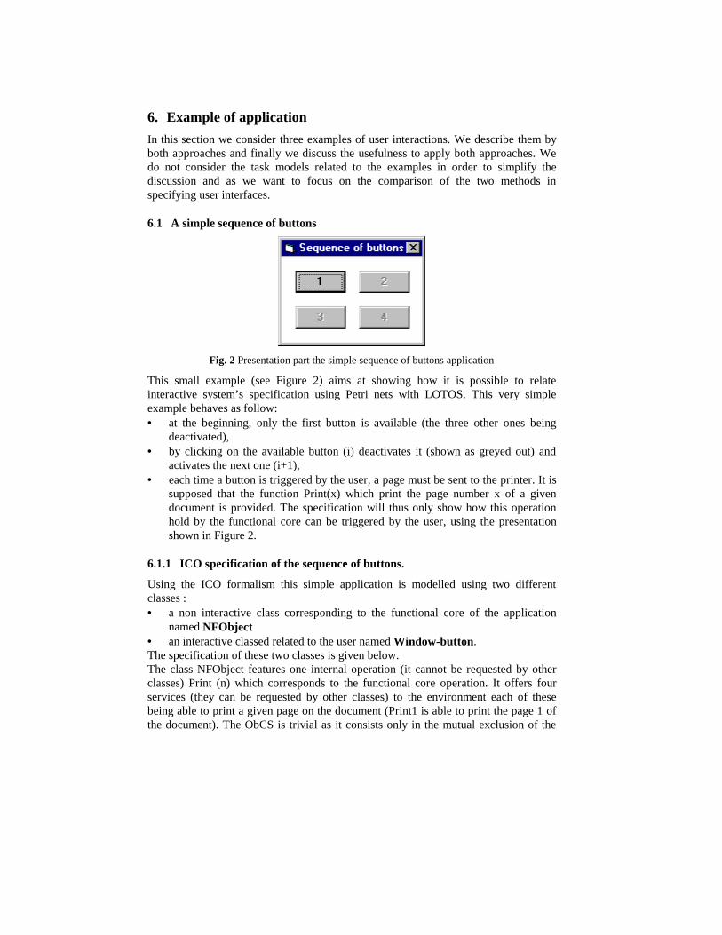
6.1 A simple sequence of buttons
Fig. 2 Presentation part the simple sequence of buttons application
This small example (see Figure 2) aims at showing how it is possible to relateinteractive system’s specification using Petri nets with LOTOS. This very simpleexample behaves as follow:• at the beginning, only the first button is available (the three other ones being
deactivated),• by clicking on the available button (i) deactivates it (shown as greyed out) and
activates the next one (i+1),• each time a button is triggered by the user, a page must be sent to the printer. It is
supposed that the function Print(x) which print the page number x of a givendocument is provided. The specification will t hus only show how this operationhold by the functional core can be triggered by the user, using the presentationshown in Figure 2.
6.1.1 ICO specification of the sequence of buttons.
Using the ICO formalism this simple application is modelled using two differentclasses :• a non interactive class corresponding to the functional core of the application
named NFObject• an interactive classed related to the user named Window-button.The specification of these two classes is given below.The class NFObject features one internal operation (it cannot be requested by otherclasses) Print (n) which corresponds to the functional core operation. It offers fourservices (they can be requested by other classes) to the environment each of thesebeing able to print a given page on the document (Print1 is able to print the page 1 ofthe document). The ObCS is trivial as it consists only in the mutual exclusion of the
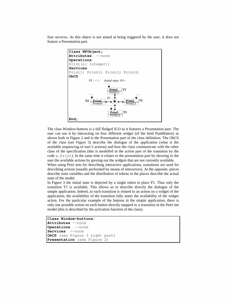
four services. As this object is not aimed at being triggered by the user, it does notfeature a Presentation part.
Class NFObject;Attributes --noneOperationsPrint(n: Integer);ServicesPrint1; Print2; Print3; Print4;ObCS
T1
P1T2
T3
T4
P1 : < >
Print4
Print3
Print2
Print1
Initial state: P1=<>
Print(4)
Print(3)
Print(2)
Print(1)
End;
The class Window-buttons is a full fledged ICO as it features a Presentation part. Theuser can use it by interacting on four different widget (of the kind PushButton) asshown both in Figure 2 and in the Presentation part of the class definition. The ObCSof the class (see Figure 3) describe the dialogue of the application (what is theavailable sequencing of user’s actions) and how the class communicate with the otherclass of the specification (this is modelled in the action part of the transition by thecode x.Print ). In the same time it relates to the presentation part by showing to theuser the available actions by greying out the widgets that are not currently available.When using Petri nets for describing interactive applications, transitions are used fordescribing actions (usually performed by means of interactors). At the opposite, placesdescribe state variables and the distribution of tokens in the places describe the actualstate of the model.In Figure 3 the initial state is depicted by a single token in place P1. Thus only thetransition T1 is available. This allows us to describe directly the dialogue of thesimple application. Indeed, as each transition is related to an action on a widget of theapplication, the availabilit y of the transition fully states the availabilit y of the widgetaction. For the particular example of the buttons in the simple application, there isonly one possible action on each button directly mapped to a transition in the Petri netmodel (this is described by the activation function of the class).
Class Window-buttons;Attributes --noneOperations --noneServices --noneObCS (see Figure 3 right part)Presentation (see Figure 2)

Widgets name: B1, caption: “1”;name: B2, caption: “2”;name: B3, caption: “3”;name: B4, caption: “4”;
Activation function (see Figure 3 left part)End;
Widget
User’sactions
Transition
B1 Click T1B2 Click T2B3 Click T3B4 Click T4
T1
P1
P4 P3
P2
T2
T3
T4
P1, P2, P3, P4 : <NFObject>
<x>
<x>
<x>
<x>
<x><x><x>
<x>
x.Print4
x.Print3
x.Print2
x.Print1
Initial state: P1= nfobject
Fig. 3 Petri net describing the behaviour of the sequence of buttons (right part) and theactivation function (left part)
The structure and the physical behaviour of the objects directly represented on thescreen (buttons and the window) are not described here as they are well known andthis description is the main point of the most user interface builders. However, most ofthe widgets available in the norm CUA [13] have been modelled using the ICOformalism. This can be found in [20].
6.1.2 LOTOS specification of the sequence of buttons.
The LOTOS specification follows the interactor model. Thus we have four interactors,one for each button and each interactor is described by one LOTOS process. Theirbehaviour is the same so we only need four instances of the same process. Thedifference among the instances of the process definition is in the gates that they use tocommunicate.The process which we define to describe the button behaviour is:
process int_but[input_receive, input_trigger, input_send, output_send, output_trigger](enabled: Bool): noexit :=input_receive; output_send; interactor_button [...] (enabled)[] input_trigger; ([enabled eq true] -> output_send; input_send; interactor_button [...](false)
[] [enabled eq false] -> interactor_button [...] (enabled))[] output_trigger; output_send; interactor_button [...] (true)endproc
This LOTOS expression describes a button which can receive in the input_receivegate the event informing that the cursor is in the button area, next there is anouput_send event which provides feedback of it (for example by highlighting theborder of the button) and then there is a recursive call to its behaviour without

modifying the state of the button. The state of the button is represented by a Booleanvariable (enabled). Alternatively ([] is the choice operator) it is possible that thebutton receives either an input_trigger event or an output_trigger event. The inputtrigger is associated with the button pressing in the button area, if the button wasenabled (this is indicated by the boolean guard [enabled]) then there is a feedback(output_send event) which means that the button changes its colour to indicate that itbecomes disabled, it provides to the outside by the output_send gate the informationthat it has been selected and it changes its state into false, otherwise nothing happensand it calls recursively its behaviour. Finally we can have the output_trigger eventwhich in this case indicates that the button becomes reactive thus it changes its colours(output_send event) and its state becomes true.The specification of the four buttons behaviour is obtained by creating four instancesof the int_but process, each of them with a specific set of gates. At the beginning onlyone process has the Boolean variable defining its state sets to true indicating that it isreactive. In the composition of the four processes we have to indicate which gates areused for synchronisation ( the |[x, y]| operator). The synchronisation occurs on the gatewhich is used to communicate to the outside that the button has been selected. Thiscommunication is provided to the next button too and it provides an output trigger forit as when it occurs the colour of the button changes other than becoming active. Thuswe obtain the following expression:
specification four_buttons [ ... ] : noexit :=int_but[cursor_in1, sel1, print1, pres_but1, print4] (true)
|[print1, print4]|(int_but[cursor_in2, sel2, print2, pres_but2, print1] (false)
|[print2]|int_but[cursor_in3, sel3, print3, pres_but3, print2] (false)
|[print3]|int_but[cursor_in4, sel4, print4, pres_but4, print3] (false))))
cursor_in1
sel1
print1
pres_but1
button 1 button 2 button 3 button 4
pres_but2 cursor_in2 pres_but3 cursor_in3 pres_but4 cursor_in4
print2 print3 print4
sel2 sel3 sel4
Fig. 4 Graphical interactor representation of the four button example
The LOTOS expression describing the int_but process is a Full LOTOS expression asit uses both process and data algebra. The data algebra is used to describe the state ofthe process, which is simply one Boolean value in this case. If we want to verifyACTL properties over this specification the Full LOTOS specification has to betranslated into a Basic LOTOS specification, which means to remove the data algebrapart. This translation can be done in automatic way but the result would be not

completely equivalent to the initial specification because the tool remove the Booleanguards ([enable eq ...] -> operators). Thus the behaviours indicated after the twoguards can occur at any time while we want that this depends on the user selections.To solve this problem we can modify the FULL LOTOS specification into anequivalent basic LOTOS specification but without using the automatic tool. The resultis described by two Basic LOTOS expressions which are mutually recursive in such away to describe the two possible behaviours of the buttons. It becomes:
process int_but_ab [input_receive, input_trigger, input_send,output_send,output_trigger] : noexit :=input_receive; output_send; int_but_ab [...][] input_trigger; output_send; input_send; int_but_disab[ ... ][] output_trigger; output_send; int_but_ab [...]endproc
process int_but_disab [input_receive, input_trigger, input_send, output_send,output_trigger] : noexit :=input_receive; output_send; int_but_disab [...][] input_trigger; int_but_disab [...][] output_trigger; output_send; interactor_but_ab [...]endproc
As you can see in the int_but_ab process is active, after an input trigger event occursthen the int_but_disab process is enabled. Vice versa when the int_but_disab processis active, after an output trigger event occurs then the int_but_ab process is enabled.
6.1.3 Discussion.
In the TLIM method the basic idea is to have the LOTOS specification of aninteractor as a template which encapsulates the main behaviour of an interactiontechnique and then when one specific interactor has to be specified only the specificactions should be provided to this template. There is a set of well defined smallmodifications of the general interactor behaviour which can be used as refinements ofthe general template (for example, only input or only output interactors, interactorswhich disappear once an input value for the application has been generated).The modifications of the presentation of an interactor are represented by theoccurrences of the output_send action. The communication with the functional core(in this example the calls to the command for printing a page) is represented by theinput_send action.In the given example the behaviour of the widgets (only PushButtons here) is verysimple and consists only in one user action with a predefined feedback (the widgetchanges its colour when clicked by the user). For this reason there is no modelli ng ofthe behaviour of the widget. However, this low level of interaction can be modelledusing the ICO formalism as described in [20, 28]. The models make clear the softwarecomponents that will exist in the implementation. The functional core is modelled by aclass as well as the window. Their communication is fully and formally expressed (seethe [3, 35] for a description of this protocol), even though no generic communication

between widgets is described as in the interactor model of TLIM. That could be a firstway of integration for the two approaches where the TLIM interactors could be usedas a generic concept during the actual design of the behaviour of the widgets.
6.2 A simple temperature translator
The display of the example is shown in Figure 5. This example allows users to type ina temperature in (Celsius or in Fahrenheit) in one of the two text boxes. If thetemperature is entered in the Celsius box then the button called CeToFa becomesavailable and if the user clicks on it the translation to Fahrenheit will be triggered andthe result will be displayed in the Fahrenheit box.
Fig. 5 The presentation part of the temperature translator application
6.2.1 Petri net specification of the temperature translator
Class Window-buttons;Attributes --noneOperations -- internalFaToCe (n: integer) : integer; begin FaToCe = 5/9*(n -32)end;CeToFa (n:integer) : integer; begin CeToFa = 32 + 9/5*n end;Services --noneObCS (see Figure 6)Presentation (see Figure 5)
Widgets name: B1, caption: “FaToCe”; name: B2, caption: “CeToFa”;name: Text1; name: Text2;
Activation functionWidget User action TransitionB1 Click T6B2 Click T5Text1 EnterKey T2,T4Text2 EnterKey T1,T3
End;
The Petri net in Figure 6 describes the dialogue of the temperature translator.At the beginning both transitions EditCelsius (T1) and EditFahrenheit (T2) can betriggered as there is a token in each of their input place. This models that the user caneither enter a temperature in Celsius or in Fahrenheit. One of these transitions can betriggered when the user has pressed the EnterKey. After triggering a transitionEditCelsius (T1) for example, both transitions EditCelsius (T3) and CeToFa (T5) can
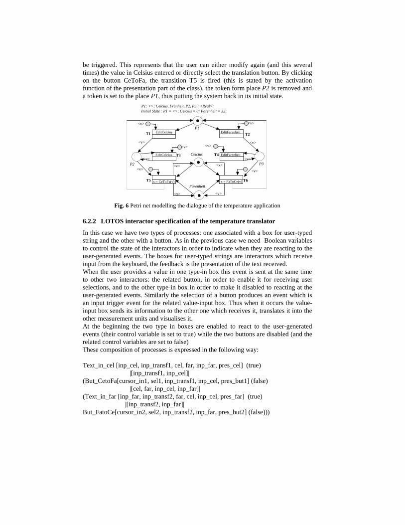
be triggered. This represents that the user can either modify again (and this severaltimes) the value in Celsius entered or directly select the translation button. By clickingon the button CeToFa, the transition T5 is fired (this is stated by the activationfunction of the presentation part of the class), the token form place P2 is removed anda token is set to the place P1, thus putting the system back in its initial state.
x:= CeToFa(v) x:= FaToCe(v)
<x>
<x>
EditCelciusT1 T2
T3 T4
T5 T6
P3P2
P1
<v>
EditFarenheit
EditFarenheit
<v>
EditCelcius Celcius
Farenheit
Initial State : P1 = <>; Celcius = 0; Farenheit = 32;P1: <>; Celcius, Franheit, P2, P3 : <Real>;
<v><v><v>
<v>
<v> <v>
<v> <v>
<v> <v>
Fig. 6 Petri net modelling the dialogue of the temperature application
6.2.2 LOTOS interactor specification of the temperature translator
In this case we have two types of processes: one associated with a box for user-typedstring and the other with a button. As in the previous case we need Boolean variablesto control the state of the interactors in order to indicate when they are reacting to theuser-generated events. The boxes for user-typed strings are interactors which receiveinput from the keyboard, the feedback is the presentation of the text received.When the user provides a value in one type-in box this event is sent at the same timeto other two interactors: the related button, in order to enable it for receiving userselections, and to the other type-in box in order to make it disabled to reacting at theuser-generated events. Similarly the selection of a button produces an event which isan input trigger event for the related value-input box. Thus when it occurs the value-input box sends its information to the other one which receives it, translates it into theother measurement units and visualises it.At the beginning the two type in boxes are enabled to react to the user-generatedevents (their control variable is set to true) while the two buttons are disabled (and therelated control variables are set to false)These composition of processes is expressed in the following way:
Text_in_cel [inp_cel, inp_transf1, cel, far, inp_far, pres_cel] (true)|[inp_transf1, inp_cel]|
(But_CetoFa[cursor_in1, sel1, inp_transf1, inp_cel, pres_but1] (false)|[cel, far, inp_cel, inp_far]|
(Text_in_far [inp_far, inp_transf2, far, cel, inp_cel, pres_far] (true)|[inp_transf2, inp_far]|
But_FatoCe[cursor_in2, sel2, inp_transf2, inp_far, pres_but2] (false)))
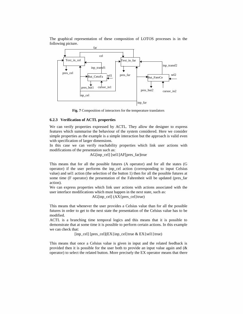
The graphical representation of these composition of LOTOS processes is in thefollowing picture.
Text_in_cel
But_CetoFa
Text_in_far
But_FatoCe
far
cel
pres_cel
inp_cel
inp_transf1
sel1 pres_far sel2
cursor_in1pres_but1
inp_far
cursor_in2pres_but2
inp_transf2
Fig. 7 Composition of interactors for the temperature translators
6.2.3 Verification of ACTL properties
We can verify properties expressed by ACTL. They allow the designer to expressfeatures which summarise the behaviour of the system considered. Here we considersimple properties as the example is a simple interaction but the approach is valid evenwith specification of larger dimensions.In this case we can verify reachabilit y properties which link user actions withmodifications of the presentation such as:
AG[inp_cel] [sel1]AF[pres_far]true
This means that for all the possible futures (A operator) and for all the states (Goperator) if the user performs the inp_cel action (corresponding to input Celsiusvalue) and sel1 action (the selection of the button 1) then for all the possible futures atsome time (F operator) the presentation of the Fahrenheit will be updated (pres_faraction).We can express properties which link user actions with actions associated with theuser interface modifications which must happen in the next state, such as:
AG[inp_cel] (AX{pres_cel}true)
This means that whenever the user provides a Celsius value than for all the possiblefutures in order to get to the next state the presentation of the Celsius value has to bemodified.ACTL is a branching time temporal logics and this means that it is possible todemonstrate that at some time it is possible to perform certain actions. In this examplewe can check that:
[inp_cel] [pres_cel](EX{inp_cel}true & EX{sel1}true)
This means that once a Celsius value is given in input and the related feedback isprovided then it is possible for the user both to provide an input value again and (&operator) to select the related button. More precisely the EX operator means that there

exists a temporal evolution where in order to get to the next state the indicated actionhas to occur.
6.2.4 Discussion
The Petri net in Figure 6 gives an immediate indication of the activation state of eachwidget. The designer can understand it by just looking at the token position. Theinteractor-specification of Figure 7 gives an immediate indication of what the widgetsused are and how they communicate. This gives us one possible way to integrate theapproach: using Petri nets for indicating the activation and deactivation of thecomponents and LOTOS interactors to describe the behaviour of each specific object.
6.3 A third example highlighting complementary analysis
This section aims at showing complementary results which can be obtained by theTLIM and the MICO methods. This is shown on a simple example that we havepreviously studied in [23].
6.3.1 Informal description of the example
The system is made up of two unconnected subsystems, the stop-watch and the lightbulb. The light bulb is controlled by a timer. The timer is triggered by a button, and itsperiod is 30 seconds. If the button is depressed while the light is on, the timer is resetand starts over counting down for 30 seconds. In order to use this system, the userneeds to use his/her hands (to push the light and stopwatch switches) and vision inorder to watch the elapsed time on the stopwatch.Note that this information is the minimum that has to be provided to the task analyst inorder to build a meaningful task model. If it is not provided, the task model designerwill have to make assumptions about the behaviour of the system or he/she will onlybe able to discuss about general goals, at a level that will not enhance further ourability to improve the system.
System partUser part
Fig. 8 The simple case study of the user keeping the light on for 3 minutes
6.3.2 Petri net modelling of the example
The model of the system is presented on Figure 9. It is made up of two components,the TimerControlledLight and the Watch. As those two components are not related,the system model is composed of two unconnected Petri nets. The Petri net
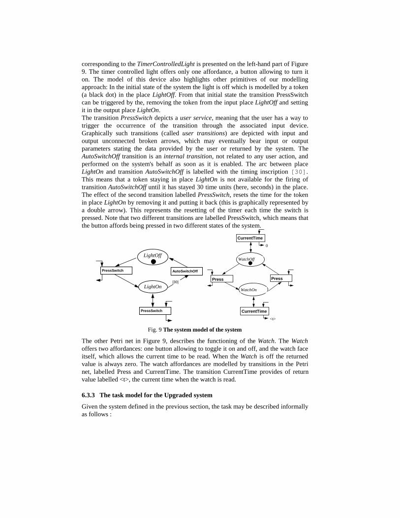
corresponding to the TimerControlledLight is presented on the left-hand part of Figure9. The timer controlled light offers only one affordance, a button allowing to turn iton. The model of this device also highlights other primitives of our modelli ngapproach: In the initial state of the system the light is off which is modelled by a token(a black dot) in the place LightOff. From that initial state the transition PressSwitchcan be triggered by the, removing the token from the input place LightOff and settingit in the output place LightOn.The transition PressSwitch depicts a user service, meaning that the user has a way totrigger the occurrence of the transition through the associated input device.Graphically such transitions (called user transitions) are depicted with input andoutput unconnected broken arrows, which may eventually bear input or outputparameters stating the data provided by the user or returned by the system. TheAutoSwitchOff transition is an internal transition, not related to any user action, andperformed on the system's behalf as soon as it is enabled. The arc between placeLightOn and transition AutoSwitchOff is labelled with the timing inscription [30] .This means that a token staying in place LightOn is not available for the firing oftransition AutoSwitchOff until it has stayed 30 time units (here, seconds) in the place.The effect of the second transition labelled PressSwitch, resets the time for the tokenin place LightOn by removing it and putting it back (this is graphically represented bya double arrow). This represents the resetting of the timer each time the switch ispressed. Note that two different transitions are labelled PressSwitch, which means thatthe button affords being pressed in two different states of the system.
PressSwitch
LightOff
LightOn
PressSwitch
[30]
AutoSwitchOff
WatchOn
<t>
WatchOff
Press
CurrentTime
Press
0
CurrentTime
Fig. 9 The system model of the system
The other Petri net in Figure 9, describes the functioning of the Watch. The Watchoffers two affordances: one button allowing to toggle it on and off , and the watch faceitself, which allows the current time to be read. When the Watch is off the returnedvalue is always zero. The watch affordances are modelled by transitions in the Petrinet, labelled Press and CurrentTime. The transition CurrentTime provides of returnvalue labelled <t>, the current time when the watch is read.
6.3.3 The task model for the Upgraded system
Given the system defined in the previous section, the task may be described informallyas follows :
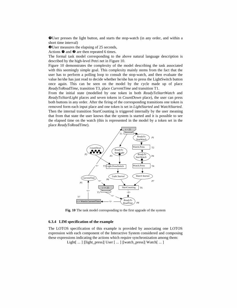
nUser presses the light button, and starts the stop-watch (in any order, and within ashort time interval)oUser measures the elapsing of 25 seconds,Actions n and o are then repeated 6 times.The formal task model corresponding to the above natural language description isdescribed by the high-level Petri net in Figure 10.Figure 10 demonstrates the complexity of the model describing the task associatedwith this seemingly simple goal. This complexity mainly stems from the fact that theuser has to perform a polli ng loop to consult the stop-watch, and then evaluate thevalue he/she has just read to decide whether he/she has to press the LightSwitch buttononce again. This can be seen on the model by the cycle made up of placeReadyToReadTime, transition T3, place CurrentTime and transition T1.From the initial state (modelled by one token in both ReadyToStartWatch andReadyToStartLight places and seven tokens in CountDown place), the user can pressboth buttons in any order. After the firing of the corresponding transitions one token isremoved form each input place and one token is set in LightStarted and WatchStarted.Then the internal transition StartCounting is triggered internally by the user meaningthat from that state the user knows that the system is started and it is possible to seethe elapsed time on the watch (this is represented in the model by a token set in theplace ReadyToReadTime).
Light.PressSwitch
t := Watch.CurrentTime ReadyToReadTime
ReadyToStartLight
CurrentTime
T1
T5
t > 25
t <= 25
Light Started
StartCounting
CountDown
<0>
ReadyToStartWatch
Watch.Press
Watch Started
<t>
<t>
<t>
<t>
<t>
Watch.Press
ReadyToStopWatch
T7
P1
T2
T4T3
T6
P2P3 P4
P5
P6P7
P8
Fig. 10 The task model corresponding to the first upgrade of the system
6.3.4 LIM specification of the example
The LOTOS specification of this example is provided by associating one LOTOSexpression with each component of the Interactive System considered and composingthese expressions indicating the actions which require synchronization among them:
Light[ ... ] |[light_press]| User [ ... ] |[watch_press]| Watch[ ... ]
The user can be specified as:process User:= User_init[ ... ] >> Visual[ ... ] |[decide_to_start]| Action[ ... ]
where User_init[ ... ] := decide_to_start; (light_press; watch_press; exit [] watch_press; light_press; exit)
User_init is the description of the user behaviour at the beginning of the interactionwhen once she/he has decided to start it then she/he presses the two buttons in anyorder. When terminated this initial behaviour activates (using the sequential enablingoperator (>> symbol)) the normal user behaviour which is described by the Visual andAction processes.
Visual[ ... ] := Read_watch; evaluate_time; (decide_to_start; Visual[ ... ][] Visual[ ... ])
Action[ ... ] := decide_to_start; (light_press; watch_press; exit []watch_press; light_press; exit) ....
In this case we consider only two parts of the user behaviour: the Visual subsystemand the Action subsystem. They communicate because after reading the watch the userevaluates the current time and if he/she decides to start the watch he/she has tocommunicate this decision to the physical part performing this action. In this case theAction process has to perform three actions six times: receiving the start stimulus andpressing the two buttons.
The watch is described by Watch[ ... ] := watch_press; Watch1[ ... ]where Watch1[ ... ] := watch_press; Watch[ ... ] [] mod_pres; Watch1[ ... ].
This means that it can receive the user action which starts it, after that it can eitherreceive another pressing of the related button which stops it or it updates itspresentation (mod_pres event) with the new time.The LOTOS expression describing the light system is:
Light[ ... ] := light_press; light_on; i; (i; light off; Light[ ... ] [] Light_system[ ... ])
This means that once the button is pressed the light is turned on and there is sometimewhich is passed in this way, next there are two possibiliti es: either sometime passedagain and then the light is turned off or a new button selection keeps again the lighton. Note that we have used internal actions (i) to represent the elapsing of timewithout any external action. In this way without using operators with explicit timeconstraints and data we can describe the system considered.
6.3.5 Proving ACTL properties on the example
We use the LOTOS model of this simple Interactive System in order to check itsproperties. The possible behaviours are not very complicated so we can checkproperties which could be verified in other ways too.For example we can check the possibilit y that at some time the light system canbehaves in different ways:AG[light_press][light_on] (<light_off>true & E[true{~light_off} U {light_on} true])
This means that whenever the sequence of the actions press_button and light_onoccurs then it is possible both that the next observable action (this means that internalactions are not considered) is the light_off event and that a temporal evolution existswhere no light_off event occurs until a new light_on action is verified. The secondbehaviour means that the user can turn on the light again before that it finishes thetime related to the previous selection.Another example of property of the user behaviour is that she/he can read the watchand then either read it again without pressing the button in the meanwhile or decide topress again the button to keep the light on. This is checked by the following ACTLexpression:
AG [read_watch] (E[true{~light_press} U {read_watch}true] & E[true{~ read_watch } U { light_press }true])
6.3.6 Comments on the third example
The specifications discussed in this section give a clear indication aboutcomplementary analysis which can be performed by the two methods. In one case,with the ICO method, it is possible to provide precise indication of quantitative time-related aspects. Vice versa with the LOTOS-based approach it possible to reasonabout temporal ordering of actions and demonstrate specific properties whichsummarise the main features of the system behaviour.
7. Conclusions
In this paper we have discussed the main concepts useful to apply formal methods inInteractive Systems design. Then we have outlined a proposal for an integrated use oftwo approaches based on different notations and we have applied both approaches tothree small case studies. We have found that Petri Nets provide a more immediate tointerpret representation of the temporal ordering among the possible actions,especially with not large specifications. Thus they are suitable to provide abstractrepresentations of the overall behaviour of the system or descriptions of smallcomponents. The TLIM method is more oriented to provide detailed descriptions ofthe system behaviour: the composition operators guarantee a good modularity in thespecifications performed which is very important for the development and themodification of large specifications. These specifications can be diff icult to interpretat the beginning but they are useful to build models which can be analysed byautomatic tools in order to check properties and to drive the development of animplementation reflecting the structure of the specification.
We believe that this integrated proposal is an interesting approach and we plan todevelop it further and to apply it to an industrial case study from the air traff ic controlapplication area.
Acknowledgements
The authors would like to acknowledge the Italian CNR and the French CNRS (by theway of the GDR-PRC-CHM) which partially supported this work under thecooperation project n° 3226.
References
1. J. Accot, S. Chatty & P. Palanque. A formal description of low levelinteraction and its application to multimodal interactive systems, in [10], SpringerVerlag 1996.
2. P. Barnard, J. May, "Interactions with Advanced Graphical Interfaces and theDeployment of Latent Human Knowledge" in [8].
3. R. Bastide. Cooperative Objects: a formalism for the design of concurrentsystems. PhD dissertation, University of Toulouse 1, 1992 (in French).
4. R. Bastide & P. Palanque. A Petri net based environment for the design ofevent-driven interfaces. 16th international conference on Application and Theory ofPetri nets, LNCS 935, Springer Verlag 1995.
5. R. Bastide & P. Palanque. Implementation techniques for Petri net basedspecifications of human computer dialogues. In proceedings of Computer AidedDesign of User Interfaces (CADUI’96), Namur, June 1996, Presses Universitaires deNamur (Pub.).
6. S. K Card., T.P. Moran & A. Newell . The psychology of Human-ComputerInteraction. Lawrence Erlbaum Associates, 1983.
7. R. DeNicola, A. Fantechi, S. Gnesi, G. Ristori, An Action Based Frameworkfor Verifying Logical and Behavioural Properties of Concurrent Systems, ComputerNetworks & ISDN Systems, Vol.25, n° 7, February 1993, pp.761-778.
8. Proceedings of the first Eurographics workshop on Design, Specification andVerification of Interactive Systems, F. Paternó Ed. Springer Verlag 1995, ISBN 3-540-59480-9.
9. Proceedings of the second Eurographics workshop on Design, Specificationand Verification of Interactive Systems, P. Palanque & R. Bastide Eds. SpringerVerlag 1995.
10. Proceedings of the third Eurographics workshop on Design, Specificationand Verification of Interactive Systems, F. Bodart & J. Vanderdonckt Eds. SpringerVerlag 1996.
11. P. Gray & C. Johnson, "Requirements for the Next Generation of UserInterface Specification Languages", Proceedings DSV-IS'95, Springer Verlag, pp.113-133.
12. R. Harston & P. Gray, "Temporal Aspects of Tasks in the User ActionNotation", Human Computer Interaction, Vol.7, pp.1-45.
13. IBM (1989) Systems Application Architecture, Common User Access.Advanced interface design guide. Package SDK Windows - June 1989.
14. ISO (1988) Information Processing Systems - Open Systems Interconnection- LOTOS - A Formal Description Technique Based on temporal Ordering ofObservational Behaviour. ISO/IS 8807, ISO Central Secretariat.
15. D. Larrabeiti , J. Quemada, S. Pavón. From LOTOS to Petri nets throughIexpansion. Proceedings of the FORTE'96 conference Chapman & Hall , October1996.
16. T. Moher, V. Dirda, R. Bastide & P. Palanque A bridging framework formodelling devices, users and interfaces. In [10], Springer Verlag 1996.
17. M. Mezzanotte & F. Paterno', "Including Time in the Notion of Interactor” ,Proceedings Workshop on Usabilit y Aspect of Time, July ‘95, Glasgow and inSIGCHI bulletin vol 28, n°2, p. 57-61.
18. M. Mezzanotte & F. Paterno', "Use of Task, User and Formal Models toSupport Development of Multimedia Interactive Systems", Proceedings of IFIPWorking Conference Domain Knowledge for Interactive System Design, pp.213-226,May 1996, Chapman & Hall.
19. M. Mezzanotte & F. Paterno', "Verification of Human-Computer Dialogueswith an Infinite Number of States", Proceedings Workshop on Formal Aspects of theHuman Computer Interface, Sheffield, September’96, Springer Verlag.
20. P. Palanque. Modelli ng user-driven interfaces using the ICO formalism. PhDdissertation, University of Toulouse I, 1992 (in French).
21. P. Palanque, R. Bastide & L. Dourte (1993) Contextual Help for Free withthe Formal Design of User Interfaces, HCI International’93, Elseiver, North Holland.
22. P. Palanque & R. Bastide. Petri net based design of user_driven interfacesusing the interactive cooperative object formalism. In [8], p. 383-401.
23. P. Palanque & R. Bastide. Task Models - System Models: a Formal bridgeover the Gap. In Critical Issues in User Interface System Engineering (Benyon &Palanque Eds.) Springer Verlag 1995.
24. P. Palanque & R. Bastide (1995) Verification of an Interactive Software byAnalysis of its Formal Specification. Proceedings of Interact'95, Norway, Chapman etHall.
25. P. Palanque & R. Bastide. Time modelli ng in Petri nets for the design ofInteractive Systems. GIST workshop on Time in Interactive Systems. Glasgow, July1995. SIGCHI bulletin vol 28 n°2, p. 43-46.
26. P. Palanque & R. Bastide. Formal specification and verification of CSCWusing the Interactive Cooperative Object formalism. People and Computer X.Proceedings of the HCI’95 conference, Huddersfield, 1995, p. 213-232.
27. P. Palanque & R. Bastide. Performance evaluation as a tool for the formaldesign of interactive systems. IEEE Computational Engineering in SystemsApplications (CESA’96) conference, Lille, July 1996, IEEE Press.
28. P. Palanque, R. Bastide, C. Sibertin, L. Dourte (1993) Design of User-DrivenInterfaces using Petri nets and Objects ; CAISE'93. LNCS nº 685, Springer-Verlag.
29. J. Peterson. Petri nets and the modelling of systems. Prentice Hall, 1981.
30. F. Paterno' & M. Mezzanotte, Analysing Matis through Interactors andACTL, Amodeus II BRA Report, sm/wp36.
31. F. Paterno' & M. Mezzanotte, "Formal Verification of Undesired Behavioursin the CERD Case Study", Proceedings EHCI'95 IFIP Working Conference,Chapman&Hall Publisher, Wyoming, August 1995.
32. S. Pangoli & F. Paterno', "Automatic Generation of Task-oriented Help",Proceedings ACM Symposium on User Interfaces Software and Technology, pp.181-187, ACM Press, Pittsburgh, November 1995.
33. F. Paterno', S. Sciacchitano & J. Lowgren, "A User Interface EvaluationMapping Physical User Actions to Task-driven Formal Specifications", ProceedingsDSV-IS'95, pp.35-53, Springer Verlag Publisher, Toulouse, June'95.
34. J. Rumbaugh, M. Blaha, W. Premerlani, F. Eddy, W. Lorensen. Objectoriented modelling and design. Prentice Hall 1991.
35. C. Sibertin-blanc. A client server protocol for the composition of Petri nets.In proceedings of Application and Theory of Petri nets LNCS 691, USA, 1993.
36. A. Sutcli ffe & P. Faraday, "Designing Presentations in MultimediaInterfaces", Proceedings ACM CHI'94, pp.92-98.
37. S. Shlaer, S. Mellor. Object oriented systems analysis. Modelli ng the worldin data. Yourdon Press, 1988.
38. R. Sisto & A. Valenzano, "Mapping Petri nets with Inhibitor Arcs onto BasicLOTOS Behaviour Expressions", IEEE Transactions on Computers, Vol.44, N.12,December 1995, pp.1361-1370.