Software License and Limited Warranty - ICO - NewTek
382
P LEASE READ CAREFULLY BEFORE INSTALLING THIS SOFTWARE. BY INSTALLING THIS SOFTWARE, YOU AGREE TO BECOME BOUND BY THE TERMS OF THIS LICENSE. IF YOU DO NOT AGREE TO THE TERMS OF THIS LICENSE, RETURN THIS PACKAGE TO THE PLACE WHERE YOU OBTAINED IT WITHIN 15 DAYS FOR A FULL REFUND. 1. Grant of License The enclosed computer program(s) (the “Software”) is licensed, not sold, to you by NewTek for use only under the terms of this License, and NewTek reserves any rights not expressly granted to you. You own the disk(s) on which the Software is recorded or fixed, but the Software is owned by NewTek or its suppliers and is protected by United States copyright laws and international treaty provisions. The copyright restrictions of this license extend to any further updates, software patches, or bug fixes made available to you by Newtek, whether distributed by floppy disc, CD ROM, or in an electronic format via BBS, ftp, email, etc. This License allows you to use one copy of the Software on a single computer at a time. To “use” the Software means that the Software is either loaded in the temporary memory (i.e., RAM) of a computer, or installed on the permanent memory of a computer (i.e., hard disk, CD ROM, etc.). You may use at one time as many copies of the Software as you have licenses for. You may install the Software on a common storage device shared by multiple computers, provided that if you have more computers having access to the common storage device than the number of licensed copies of the Software, you must have some software mechanism which locks out any concurrent user in excess of the number of licensed copies of the Software (an additional license is not needed for the one copy of Software stored on the common storage device accessed by multiple computers). You may make one copy of the Software in machine readable form solely for backup purposes. The Software is protected by copyright law. As an express condition of this License, you must reproduce on the backup copy the NewTek copyright notice in the following format “(c) 2003 NewTek” You may permanently transfer all your rights under this License to another party by providing such party all copies of the Software licensed under this License together with a copy of this License and all written materials accompanying the Software, provided that the other party reads and agrees to accept the terms and conditions of this License. 2. Restrictions The Software contains trade secrets in its human perceivable form and, to protect them, YOU MAY NOT REVERSE ENGINEER, DECOM- PILE, DISASSEMBLE, OTHERWISE REDUCE THE SOFTWARE TO ANY HUMAN PERCEIVABLE FORM. YOU MAY NOT MODIFY, ADAPT, TRANSLATE, RENT, LEASE, LOAN, RESELL FOR PROFIT, OR CREATE DERIVATIVE WORKS BASED UPON THE SOFTWARE OR ANY PART THEREOF. 3. Termination This License is effective until terminated. This License will terminate immediately without notice from NewTek or judicial resolution if you fail to comply with any provision of this License. Upon such termination you must destroy the Software, all accompanying written materials and all copies thereof. You may also terminate this License at any time by destroying the Software, all accompanying written materials and all copies thereof. 4. Export Law Assurances You agree that neither the Software nor any direct product thereof is being or will be shipped, transferred or re-exported, directly or indirect- ly, into any country prohibited by the United States Export Administration Act and the regulations thereunder or will be used for any pur- pose prohibited by the Act. License.1 Software License and Limited Warranty
-
Upload
khangminh22 -
Category
Documents
-
view
2 -
download
0
Transcript of Software License and Limited Warranty - ICO - NewTek

PLEASE READ CAREFULLY BEFORE INSTALLING THIS SOFTWARE. BY INSTALLING THIS SOFTWARE,YOU AGREE TO BECOME BOUND BY THE TERMS OF THIS LICENSE. IF YOU DO NOT AGREE TO THE
TERMS OF THIS LICENSE, RETURN THIS PACKAGE TO THE PLACE WHERE YOU OBTAINED IT WITHIN 15DAYS FOR A FULL REFUND.
1. Grant of License
The enclosed computer program(s) (the “Software”) is licensed, not sold, to you by NewTek for use only under the terms of this License,and NewTek reserves any rights not expressly granted to you. You own the disk(s) on which the Software is recorded or fixed, but theSoftware is owned by NewTek or its suppliers and is protected by United States copyright laws and international treaty provisions.
The copyright restrictions of this license extend to any further updates, software patches, or bug fixes made available to you by Newtek,whether distributed by floppy disc, CD ROM, or in an electronic format via BBS, ftp, email, etc.
This License allows you to use one copy of the Software on a single computer at a time. To “use” the Software means that the Software iseither loaded in the temporary memory (i.e., RAM) of a computer, or installed on the permanent memory of a computer (i.e., hard disk,CD ROM, etc.).
You may use at one time as many copies of the Software as you have licenses for. You may install the Software on a common storagedevice shared by multiple computers, provided that if you have more computers having access to the common storage device than thenumber of licensed copies of the Software, you must have some software mechanism which locks out any concurrent user in excess ofthe number of licensed copies of the Software (an additional license is not needed for the one copy of Software stored on the commonstorage device accessed by multiple computers).
You may make one copy of the Software in machine readable form solely for backup purposes. The Software is protected by copyright law.As an express condition of this License, you must reproduce on the backup copy the NewTek copyright notice in the following format“(c) 2003 NewTek”
You may permanently transfer all your rights under this License to another party by providing such party all copies of the Software licensedunder this License together with a copy of this License and all written materials accompanying the Software, provided that the otherparty reads and agrees to accept the terms and conditions of this License.
2. Restrictions
The Software contains trade secrets in its human perceivable form and, to protect them, YOU MAY NOT REVERSE ENGINEER, DECOM-PILE, DISASSEMBLE, OTHERWISE REDUCE THE SOFTWARE TO ANY HUMAN PERCEIVABLE FORM. YOU MAY NOT MODIFY,ADAPT, TRANSLATE, RENT, LEASE, LOAN, RESELL FOR PROFIT, OR CREATE DERIVATIVE WORKS BASED UPON THE SOFTWAREOR ANY PART THEREOF.
3. Termination
This License is effective until terminated. This License will terminate immediately without notice from NewTek or judicial resolution if you failto comply with any provision of this License. Upon such termination you must destroy the Software, all accompanying written materialsand all copies thereof. You may also terminate this License at any time by destroying the Software, all accompanying written materialsand all copies thereof.
4. Export Law Assurances
You agree that neither the Software nor any direct product thereof is being or will be shipped, transferred or re-exported, directly or indirect-ly, into any country prohibited by the United States Export Administration Act and the regulations thereunder or will be used for any pur-pose prohibited by the Act.
License.1
Software Licenseand Limited Warranty

5. Limited Warranty and Disclaimer, Limitation of Remedies and Damages.
YOU ACKNOWLEDGE THAT THE SOFTWARE MAY NOT SATISFY ALL YOUR REQUIREMENTS OR BE FREE FROM DEFECTS. NEWTEKWARRANTS THE MEDIA ON WHICH THE SOFTWARE IS RECORDED TO BE FREE FROM DEFECTS IN MATERIALS AND WORK-MANSHIP UNDER NORMAL USE FOR 90 DAYS FROM PURCHASE, BUT THE SOFTWARE AND ACCOMPANYING WRITTEN MATERI-ALS ARE LICENSED “AS IS.” ALL IMPLIED WARRANTIES AND CONDITIONS (INCLUDING ANY IMPLIED WARRANTY OF MER-CHANTABILITY OR FITNESS FOR A PARTICULAR PURPOSE) ARE DISCLAIMED AS TO THE SOFTWARE AND ACCOMPANYINGWRITTEN MATERIALS AND LIMITED TO 90 DAYS AS TO THE MEDIA. YOUR EXCLUSIVE REMEDY FOR BREACH OF WARRANTYWILL BE THE REPLACEMENT OF THE MEDIA OR REFUND OF THE PURCHASE PRICE. IN NO EVENT WILL NEWTEK OR ITSDEVELOPERS, DIRECTORS, OFFICERS, EMPLOYEES OR AFFILIATES BE LIABLE TO YOU FOR ANY CONSEQUENTIAL, INCIDENTALOR INDIRECT DAMAGES (INCLUDING DAMAGES FOR LOSS OF BUSINESS PROFITS, BUSINESS INTERRUPTION, LOSS OF BUSI-NESS INFORMATION, AND THE LIKE), WHETHER FORESEEABLE OR UNFORESEEABLE, ARISING OUT OF THE USE OR INABILITYTO USE THE SOFTWARE OR ACCOMPANYING WRITTEN MATERIALS, REGARDLESS OF THE BASIS OF THE CLAIM AND EVEN IFNEWTEK OR AN AUTHORIZED NEWTEK REPRESENTATIVE HAS BEEN ADVISED OF THE POSSIBILITY OF SUCH DAMAGES.
The above limitations will not apply in case of personal injury only where and to the extent that applicable law requires such liability. Becausesome jurisdictions do not allow the exclusion or limitation of implied warranties or liability for consequential or incidental damages, theabove limitations may not apply to you.
6. General
This License will be construed under the laws of the State of Texas, except for that body of law dealing with conflicts of law. If any provisionof this License shall be held by a court of competent jurisdiction to be contrary to law, that provision will be enforced to the maximumextent permissible, and the remaining provisions of this License will remain in full force and effect. If you are a US Government end-user,this License of the Software conveys only “RESTRICTED RIGHTS,” and its use, disclosure, and duplication are subject to FederalAcquisition Regulations, 52.227-7013 (c)(1)(ii). (See the US Government Restricted provision below.)
7. Trademarks
VT, VT[3] and Aura are trademarks of NewTek. LightWave and LightWave 3D are registered trademarks of NewTek. Pentium is a trademarkof Intel. All other brand names, product names, or trademarks belong to their respective holders.
8. US Government Restricted Provision
If this Software was acquired by or on behalf of a unit or agency of the United States Government this provision applies. This Software:
(a) Was developed at private expense, and no part of it was developed with government funds,
(b) Is a trade secret of NewTek for all purposes of the Freedom of Information Act,
(c) Is “commercial computer software” subject to limited utilization as provided in the contract between the vendor and thegovernment entity, and
(d) In all respects is proprietary data belonging solely to NewTek.
For units of the Department of Defense (DoD), this Software is sold only with “Restricted Rights” as that term is defined in the DoDSupplement to the Federal Acquisition Regulations, 52.227-7013 (c) (1) (ii).
Use, duplication or disclosure is subject to restrictions as set forth in subdivision (c) (l) (ii) of the Rights in Technical Data and ComputerSoftware clause at 52.227-7013. Manufacturer: NewTek, 5131 Beckwith Boulevard, San Antonio, TX 78249.
If this Software was acquired under a GSA Schedule, the US Government has agreed to refrain from changing or removing any insignia orlettering from the software or the accompanying written materials that are provided or from producing copies of manuals or disks(except one copy for backup purposes) and:
(e) Title to and ownership of this Software and documentation and any reproductions thereof shall remain with NewTek,
(f) Use of this Software and documentation shall be limited to the facility for which it is required, and,
(g) If use of the Software is discontinued to the installation specified in the purchase/delivery order and the US Governmentdesires to use it at another location, it may do so by giving prior written notice to NewTek, specifying the type of computerand new location site. US Governmental personnel using this Software, other than under a DoD contract or GSA Schedule,are hereby on notice that use of this Software is subject to restrictions which are the same as or similar to those specified.
License.2

Software Engineering: Andrew Cross, Pat Brouillette, Mike Watkins, James Killian, Masaaki Konno, Jamie Finch, Bob Hood, Kevin Nations / Argon Hennley, Michael ‘Aussie’ Holten, Jeremy Wiseman
Hardware Engineering: Kevin Rouviere, Charles Steinkuehler, Dale Whitt, Menghua Wang
Product Evangelist: Paul Lara
Acknowledgements: Tim Jenison, Jim Plant, Nathalie Cross, Calypso Cross, Lisa Brouillette, Sam Brouillette, Heather Watkins, Sophie Brouillette, Janey Wiseman, Pat Wiseman, Erin McAuliffe, Paul Goldberg, Brian Jansen, Kurt Henning, Ted Ruiz, Harlan Hill, Eugene Kosarovich, Faraz Ahmed, Rob Berry, Brian Ehlers, Matthew Lara, Robin Nations, Atticus Nations, Remi Nations, Erica Holten, Jennifer Holten, David Holten, Rick Pingry, All our dealers, All of our Beta Testers
Documentatation
Writing a manual is like catching a whale by the tail. You are dragged out to sea for a wet and wild ride. Holdingon is damned impossible. However, since Andrew Cross answered emails 24 hours a day and Paul Lara evenvacationed with draft chapters under his arm, the behemoth was befriended.
Creating the manual was a team effort. To prep the book for press, Molly Dinkins, my partner, provided theelbow grease: she did all the diurnal dirty duties, as well as contributed her artistic and editing credentials. JimCullers spent two months of dedicated checking, chuckling and chipping away at chapter after chapter, testingevery new beta build thrust his way.
Alonso Alvarez de Araya endured daily ups and downs to design and layout the shape-shifting beast.
Aura guru Steve Bowie penned, polished and primped an updated version of the Aura manual.
Anita Pantin, Jim, Randy Howard, Stephanie Dinkins, and Graham Toms contributed artistic embellishments ofmoving and motionless graphics, video, paintings and photography. The looping backgrounds were provided byAnita and Sjon Ueckert from www.ScreenCaffeine.com.
And hopefully Donetta Colboch survived another seismic spin on Space Mountain.
Dick De Jong
Preface.1
Credits

About the Manual
This manual describes the settings in VT [3] and explains how to work with them in the context of a video pro-duction. Each chapter focuses on a specific VT [3] panel. As you will discover, this document is not strictly areference manual. It contains numerous step-by-step examples, which were designed to illuminate the use ofVT [3]'s features. Obviously, you do not need to go through every step. There will not be a pop quiz at the endof the chapter. Use the mini-tutorials as launch pads to explore the depth of the software. Also, sample videoclips and stills have been provided on the VT [3] Manual Content CD. If you have your own clips that you wantto use, please do so.
Every attempt was made to capture the screens from the shipping version of VT [3]. Since engineering wastweaking the product until the day it was shipped, (which is a good thing), you may find some images that donot exactly match what you are seeing on your screen. One of the advantages of packaging the manual in aloose-leaf binder is that you can download, print, and insert any changes and addenda. Also, all of the imageswere captured in color; and you have the full color version at your fingertips. You will find the color PDFs in theVT3 directory in the Documentation folder.
As always, we are attempting to make the best possible software and documentation. If you have any com-ments or suggestions on the manual, please email them to [email protected].
Manual Conventions
AttenticonsThe Warning, Note and Hint attenticons draw your attention to special information about tools or features.
WARNING
Pay close attention to Warning icons; the information in a Warning is critical to working correctly with thesoftware.
NOTE
You get useful information in a Note that may help you work more efficiently or help you understand thetool better.
HINT
Hints give you shortcuts or other approaches to working quickly with tools.
Text FormattingThroughout the manual, formatting indicates how a tool or shortcut relates to the software and your computer.
BoldItems in bold are options, buttons, or fields in the software interface, such as the Font option. Bold also indi-cates keys on the keyboard that you need to type, such Ctrl. If you need to hold down a key while typinganother, the combination is shown with a +, for example, Ctrl + v.
Mouse ActionsThe manual often directs you to click, double-click or right-click the mouse button. Click and double-click referexclusively to the left mouse button. Double-clicking means to click the left mouse button twice in rapid succes-sion. Right-click refers to the right button on your mouse. In VT [3], right-clicking often brings up a ContextMenu specific to the location in which you are clicking.
Video 101Occasionally, you will see shaded areas labeled Video 101. These sidebars contain information about video andvideo processes that are not essential to using VT [3], but may help you understand why some features workthe way they do.
Preface.2

VT[3] is a combination of hardware and software consisting of a 3/4-length, 32-bit PCI Capture card, asoftware bundle and video input and output cables to connect VT [3] to your video gear. The base unit
includes:
Manuals VT [3] Card Software CD Set of content CD’s Two cables with five BNC connectors for Component, Y/C and Composite input and output
VT [3] is a Windows 2000/XP-based product that processes pristine, uncompressed or compressed multi-format video in real-time. The video production suite includes real-time nonlinear editing (editor supporting multi-ple compressed video formats), live switching and keying, batch capturing, character generation, audio andvideo processing, and Internet streaming. Integrated into the VT [3] software bundle, LightWave 3D providespowerful 3D animation tools, and Aura is a muscular video painting and compositing program.
SX-8 Expansion Module
The optional SX-8 Switcher Expansion module provides 8 Component, 8 Y/C or 24 Composite video inputs.The rack-mountable unit also includes four video outputs each for Component, Y/C, and Composite, and bal-anced and unbalanced audio stereo inputs and outputs. The three RS-422 ports furnish machine control con-nections to both playback and record decks. A fully integrated audio mixer is included as well. (For more infor-mation about the SX-8 functions, see Chapter 2.)
RS-8 Switcher Control Module
The optional RS-8 Switcher Control Module gives you an external Switcher interface with real buttons and aT-bar that you can manipulate by hand, which allows tactile video switching controls for technical directors. Thisfrees the keyboard for alternate control of Character Generator or DDR’s. The RS-8 connects to your computervia a USB cable, and can be used with or without the SX-8. (For more information about the RS-8 functions,see Chapter 9.)
SDI
The optional Serial Digital PCI card allows switch, capture or output of a single stream of SMPTE 259MSerial Digital Video. The SDI card can be assigned as a Switcher input, and works in concert with the SX-8Switcher Expansion unit. (For more information about the SDI card functions, see Chapter 2.)
Genlock
The optional Genlock card connects directly to the VT [3] card, and does not require an additional PCI slot.This device will receive house sync and genlock VT [3] to an existing sync source being shared by otherdevices.
1.1
Chapter 1: Introduction andInstallation

SYSTEM REQUIREMENTSIf you have not bought a computer system for your VT [3] card or you are looking to upgrade, the first rec-
ommendation would be to consult your local NewTek authorized dealer. They have valuable experience inmatching a system to your production needs.
Dealing with specific configurations is beyond the scope of this manual. What we do suggest is that you pur-chase the biggest, baddest computer that you can. Because when it comes to real-time video processing, VT[3] dispenses with the traditional custom hardware-centric approach and recruits the CPU for all the heavy lift-ing; meaning the faster your machine, the more video effects and manipulations you will be able to perform inreal-time.
For reference, a good base system would be:• Intel Pentium 4 Xeon or Dual AMD Opteron processor, 2.4GHz or faster • 512 MB RAM.• Four Ultra160-SCSI drives, with the controller on a 64bit PCI bus.• nVidia GeForce 4 graphics card (Minimum resolution 1280x1024).• UDMA IDE system drive• Windows 2000 (SP3) or XP Professional (SP1)
VT [3] supports dual processors. You will see significant performance improvements in all VT [3] moduleswhen you add a second processor to your machine. Also, more RAM will enhance VT [3]’s performance.Especially if you are using Aura and LightWave, opt for 1GB of RAM or more.
Also consider using two monitors. A dual monitor setup affords you more room to spread out all the cool VT [3]features and can make your workflow more efficient. They also can ease multi-tasking between other applications.
Different uses (e.g. live switching vs. DV editing) stress different system resources. While some require maxi-mum disk throughput, other situations benefit from higher memory bandwidth. Therefore, we have posted sug-gestions for the minimum specifications suitable to your production requirements on our website:www.newtek.com. Additionally, as new technology and revised versions of VT [3] become available, system rec-ommendations will be updated. Again, refer to the website for the latest information.
Even if your system does not meet the minimum requirements outlined on the website, VT [3] was designed tobe extremely scalable. Except for some Switcher tasks, the feature set gracefully adapts to slower machines.
Video Hard Drive RequirementsYou achieve optimum output with VT [3] when you use uncompressed video. To capture uncompressed
video, you need a software-striped drive array that meets the 70MB/second (or faster) data transfer requirementfor VT [3]. Drive arrays stripe multiple drives together as a single, ultra-fast hard drive. Usually, you need at leastfour hard drives in your stripe set for an IDE or SCSI configuration to meet 70MB/second sustained throughput.VT obtains the best performance using a software-striped RAID 0 with a SCSI controller. Avoid using dedicatedhardware RAID controllers, as they are not as good as SCSI controllers with sustained bandwidth.
Hard drives are connected to your hard disk controller card (not supplied) which is either installed in a PCIslot or integrated on your computer motherboard. The key to a successful video array, or stripe set, is a fast,high performance hard drive controller. Hard drive technology is constantly evolving; but at this time, Ultra-SCSIis the recommended controller for VT [3] because of its dependable sustained throughput. It currently providesthe most bandwidth, reliability, and expandability for your investment. While advances in UltraATA technology(an IDE drive) have won some converts for its price/performance, SCSI still remains faster and more reliable.Consult your NewTek dealer or our website for up-to-the-minute suggestions.
HINT
Some motherboard-based SCSI controllers do not share bandwidth between the PCI bus and disk con-trollers, and this leaves more PCI bandwidth for VT [3]. You’ll see increased performance with a disk con-troller on a 64-bit PCI bus.
1.2

Another consideration is storage space. One second of uncompressed video needs 22 MB of hard drivespace. With 3,600 seconds in an hour, that equals 79,200 MB (79.2 GB) of hard drive space to digitally storeone hour of uncompressed video.
VT [3] also supports compressed video formats at different frame rates. These formats and rates require lesshard drive space. For example, an hour of DV footage takes only 12.9 GB of storage.
Because VT [3] uses the Windows NTFS file system, the video files that you capture are not limited to the old2 GB partition size. The NTFS address size is 64 bits, which expands the maximum recording time to 27,854years.
INSTALLATION VT [3]
Hardware Installation: VT CardInstalling the VT Card is a fairly straightforward operation, but if you are starting to sweat just thinking about
opening up your computer, then consider letting your friendly NewTek dealer get under the hood.
Take care when you install the VT card. Avoid touching any of the components on the card. Ground yourselfbefore you touch the card or your computer board.
If you are adding the optional SX-8 breakout box or SDI card to your system, then please refer to those spe-cific instructions later in the chapter. The following pertains to just installing the VT card.
1. Turn off your computer and all peripherals, and disconnect the power cord from your computer. To avoiddamaging the processor and electrical components in the system, take precautions against electrostatic dis-charge (ESD) by using ground straps, gloves, or ESD mats.
2. Remove the computer cover. Then locate a free PCI slot and remove the slot’s cover. Keep the retainingscrew nearby.
3. Carefully insert the VT card into the slot. Make sure that it seats totally down into the slot, but do not try toforce it.
4. Secure the card with the removed slot cover’s retain-ing screw.
5. Replace the computer cover and reconnect the power.
6. Turn on the computer and install VT [3] software.
Software Installation: VT [3]NOTE
You must have Administrator rights/privileges when you install the software.
1. If you have an earlier version of VT software on your computer, you must uninstall it before you install VT [3].If this is the first installation of VT software on your computer, proceed to Step 2.
1.3
Illustration by Argon Hennley

To remove an older version of VT software, click on the Start button on your Windows desktop and underSettings choose Control Panel. Open Add/Remove Programs and click on the VT software in the menu,which will expand the listing. Click Change/Remove and an InstallShield Wizard will open. Be sure to click onRemove.
The Wizard should perform the operation. When it’s finished, it will ask you if you want to reboot the system.Say Yes. When your computer reboots, go to Step 2.
2. Insert the VT [3] Program CD-ROM in the appropriate drive. The installation procedure should run automati-cally. If not, double-click on the My Computer icon and double-click on the drive letter to open the drive win-dow. Double-click on the Setup.exe icon.
3. Follow the instructions within each of the setup dialogs. When you have set the options as desired, click theNext button to proceed to the next setup dialog.
NOTE
You may be prompted with a Digital Signature Not Found panel occasionally. When asked Do you wantto continue with the installation?, click on Yes.
You will be asked, Do you want to install 3rd Party Application Plugins? NewTek has worked with various
3rd Party providers to ensure compatibility. If you use programs like Digital Fusion, AfterEffects, or TMPGEnc(to name a few), say Yes. VT [3] will search your computer for the location of these programs.
4. When the installation is complete, you will need to reboot your system to install the VT [3] driver. After that,the VT [3] icon should be on your Windows desktop. After you have connected your audio and video cablesand striped your hard drives, you should be ready to launch the software. (See Chapter 3: VT [3] Interface.)
The first time you click on the VT [3] icon, you will be told to run the License program before you can accessVT [3]. If your system is connected to the Internet, the requester panel provides a direct link tohttp://register.newtek.com and will even insert your VT card’s unique ID number into the registration form. Thesoftware serial number requested at the top of the form can be found on your VT [3] box and also on the sleeveof your software CD. After filling out all the required information, you will be sent a registration key as an e-mailattachment. Save this file, (License.exe), on a floppy or CD, as you can use it if you ever move your VT toanother system or (gasp!) need to re-format your hard drive. Simply copy this file to your VT system (if it is e-mailed to another computer) and double-click it to run. A window will pop up informing you that you are nowregistered.
5. Click on the VT [3] icon again and it will ask you to choose the video format that you are using: NTSC (US),NTSC (Japan), or PAL. Pick one. You can change it later in the Preferences menu.
6. Next, since this is the first time you have used the software, you are automatically taken to a VT [3] AutoConfig program, which examines your computer system and makes some educated guesses about some ofthe program’s settings and defaults. Again, you can tweak many of these later in the Preferences menu.
1.4

In addition, Autoconfig tests the speeds of your hard drives to see if their read and write times are fastenough for video work. (Again, you need about 22 MB per second to handle one stream of uncompressedvideo.) The program also will ask if you want to turn Indexing Off on your hard drives. Indexing can slow theirperformance, so say Yes.
Finally, Autoconfig will try to locate any video decks or FireWire devices attached to your system. Don’t worryif you don’t have them attached. You can always add and configure them later in VT [3].
NOTE
If you are upgrading from an older version of VT[3] you might be prompted to update your VT core, whichthe software does for you.
Autoconfig will say when it is finished. Click Enter to exit.
You are ready to explore VT [3].
Connecting the Video and Audio Cables to the VT CardThe VT [3] card gives you one input and one output for video and for audio. (For additional inputs and out-
puts, you must have the SX-8. See Chapter 2.)
The back of the VT card has four connectors: two audio 1/8” stereo mini-jacks and two video ports. If youare using the VT card without the SX-8 hardware, you plug your audio and video in and outputs directly tothese connectors.
1. The VT card accepts one unbalanced stereo audio input in the 1/8” stereo mini-jack on the end of the card(Audio In). The audio cables are not supplied.
2. To monitor audio out of the VT card, plug in a 1/8” stereo mini-plug into the mini-jack (Audio Out) closest tothe video connectors.
3. Each video cable supplied with the VT [3] hardware bundle lets you attach one component, S-video, or com-posite video device at a time. The cables have 5 color-coded BNC connectors on one end. Plug the other endof the cables into the video ports on the VT card.
4. The port on the outside is Video Out. You can connect this cable to atelevision monitor or the input of your video deck.
5. The inside port is Video In. Connect its cable to a camera or the outputof your video deck.
6. If you are connecting a Composite video source, attach it to the GrayBNC connector.
7. For Component, use the Green: Luminance (Y), Blue: Chrominance
1.5

(U), and Red: Chrominance (V) connectors. Make sure they match the Component inputs or outputs on yourvideo deck.
8. For S-Video, you will need an S-Video adapter that has a green and a red BNC connector on one end andan S-Video connector on the other. Plug the BNCs with the matching ones on the VT card cable (Green:Luminance [Y] and Red: Chrominance [V]).
9. You need to check if Windows seesyour VT card as the default sound card.From the Windows desktop, click theStart button, under Settings, selectControl Panel. Open Sounds andMultimedia (Sounds and Audio Devicesin XP) and click on the Audio tab. VideoToaster Audio Out should be thePreferred Device of Sound Playbackand Video Toaster Audio In should bePreferred Device of Sound Recording. Ifthey are not, select them with the arrowkey next to the boxes. Click OK to closethe panel and you should be ready tocapture and playback audio and videofrom VT [3]. (See Chapter 4: Video andAudio Capture.)
NOTE
We recommend that you have no other audio cards installed on your VT [3] computer.
1.6
Windows 2000 Windows XP

Striping Hard DrivesVT [3] uses Windows support for striping two or more drives together to achieve fast transfer speeds.
To create a stripe set:
1. Right-click on the My Computer icon and choose Manage.
2. Under Storage, click Disk Management.
3. Right-click on one of the drives you want to use for the stripe set.
4. Choose Create Volume, then pick Stripe Set from the next menu.
5. Now select the other drives and click Add.
6. Make sure you choose NTFS for a file system and select Full Format and the default settings. Then clickNext and OK. The drives will start formatting. The nice thing about Windows 2000 and XP is that they containa built-in Disk Defragmenter.
1.7

INSTALLING THE SX-8 HARDWARETo use the SX-8 hardware, you must attach a daughter card, which connects to the VT Card via the bridge
card. (If you plan to use both the SX-8 hardware and the SDI card, you must use a special three-connectorbridge card.)
1. Avoid touching any of the components on the cards. Ground yourself before you touch the cards or yourcomputer board.
2. Turn off your computer and all peripherals, and disconnect the power cord from your computer. To avoiddamaging the processor and electrical components in the system, take precautions against electrostatic dis-charge (ESD) by using ground straps, gloves, or ESD mats.
3. If your VT card is already installed, open your computer and remove it.
4. Press the bridge card firmly into the edge connectors on the VT [3] card and daughter card. Be sure connec-tors are aligned correctly.
5. Find an unused floppy drive power supply connector and plug into connector on daughter card. Observepolarity. The daughter card furnishes the power to the SX-8 hardware and LED indicators, and it enables phan-tom power for microphones.
HINT
If you don’t have an unused floppy drive power connector available, you need a power supply cable tofloppy drive adapter.
Then plug the four pronged power supply end to an unused power supplycable and the smaller floppy drive power connector into your daughter card.
6. Re-install the VT [3] Card with attached daughter card. Be sure it is seatedfirmly.
7. Since the daughter card’s faceplate is attached by a ribbon cable, you caninstall the faceplate in any convenient slot. Or you can remove the 15-pin con-nector from the slot cover and install it in an available serial port knock-out onthe back of your computer.
8. Connect supplied cables from computer to the SX-8 carefully to assure that connections are correct. (Seebelow.)
1.8
Attach Daughter card to bridge card.Illustration by Argon Hennley
Attach the bridge card to the edge connector.Illustration by Argon Hennley

Attaching the SX-8 Hardware to the VT CardComputer Connections
The computer connections are at the bottom right of the SX-8. You use the four cables packaged with theSX-8 to connect with the VT card and the daughter card in the computer.
The VT Audio 1,2 cable is the thinnest of the four cables and it connects audiobetween the SX-8 and the VT [3] audio ports. This line actually feeds informationbetween the SX-8 and the VT [3] software. The cable has two 1/8” stereo mini-plugs onone end. The plugs are marked with arrows. The plug with the arrow pointing in towardsthe computer obviously plugs into the Audio In, which is the mini-jack farthest away fromthe video connectors. Connect both and then attach the other end into the TV Aud 1,2port on the SX-8.
VT Video
Three connections, VT 4, 3, and 5, provide the input and output for video between theSX-8 and your host computer. Why are they labeled 4, 3, and 5 and why are they out oforder? To give the SX-8 character and to optimize the circuitry inside the board.
• VT 4 is for video output from the VT Card. Connect the cable from VT 4 on the SX-8 to the first serialport on the left of the VT Card (the outside one).• VT 3 is for input. Connect the cable from VT 3 to the second serial port (the inside one). • VT 5 is for the daughter card. Attach the cable from VT5 on the SX-8 to the daughter card serial port.
1.9
Illustration and instructions provided by Dexter Welton.

The cables that you use forthese connections are pack-aged with the breakout box; ifyou need longer cables, youcan use standard VGA cables.
WARNING
The SX-8 has been tested with 6 foot and 10 foot cables. Since they are transferring high-frequency ana-log signals using longer cables may introduce signal interference or signal loss.
INSTALLING THE RS-8You do not need to open your computer to install the RS-8.
1. Plug supplied USB cable into the back of RS-8 using the square RS-8 port.
2. Plug the wider, computer port end of the cable into an available USB 1.1 or USB 2.0 port on the VT [3] hostcomputer.
3. Windows will detect the new USB device and begin installation.
4. When Hardware Wizard launches, click Next.
5. Choose the default Search for a suitable driver.
6. Select Specify a location.
7. Click Browse to point to the driver’s location on the computer. Navigate to VT3\Drivers\RS8 USB Driversfolder, and click Open.
9. Click OK.
10. Click Next, once Windows sees it has the proper device
11. Click Finish to complete installation
1.10

12. Launch VT [3], open Preferences and under Switcher, set Switcher Surface connected to Automaticallydetect RS8.
13. Click Close on Preferences panel and exit VT [3].
14. When you launch VT [3], the T-bar status lights on the RS-8 will begin flashing. This indicates that VT [3]sees the RS-8 device, but does not know the current position of the T-bar. Initialize the system by moving the T-bar on the RS-8 through one full cycle (either up or down).
15. This action will launch the Switcher onscreen module if it is not already open.
For detailed information on the RS-8’s controls, see Chapter 2.
INSTALLING THE SDI CARDAdding an SDI Card can prove a little trickier because it piggybacks onto the VT Card so you need to clear
two contiguous PCI slots on your motherboard. The SDI Card attaches to the VT Card via the bridge card. (Ifyou plan to use both the SX-8 hardware and the SDI card, you must use a special triple bridge card.)
1. Avoid touching any of the components on the cards. Ground yourself before you touch the cards or yourcomputer board.
2. Turn off your computer and all peripherals, and disconnect the power cord from your computer. To avoiddamaging the processor and electrical components in the system, take precautions against electrostatic dis-charge (ESD) by using ground straps, gloves, or ESD mats.
3. If your VT card is already installed, open your computer and remove it.
4. Press the bridge card firmly into the edge connectors on the VT [3]card and the SDI card. Be sure connectors are aligned correctly.
5. Locate a free PCI slot directly below the VT card and remove theslot’s cover.
6. Carefully insert both cards into their slots.
7. Secure both cards with a retaining screw.
8. Replace the computer cover and reconnect the power.
1.11
Illustration by Kevin Nations

PC Monitor Resolution and Refresh RateTo view all of the VT [3] panels correctly, you should set your monitor resolution to at least 1280 x 1024. (If
you have young eyes or a huge monitor, you can try higher resolutions, but you need 1280 x1024 as a mini-mum.)
Ideally, you should set your PC monitor’s refresh rate to 60Hz when you edit NTSC video (75Hz for PAL).This rate improves the appearance of video played back through VT-Vision on your PC monitor. If you prefer towork with a higher refresh rate, this might degrade the quality of the VT-Vision display.
To Verify Monitor Resolution and Refresh Rate
1. Click on the Start button on the Windows task bar.
2. Choose Settings > Control Panel.
3. In the Control Panel, double-click on Display.
4. In the Display Properties panel, choose the Settings tab and then click on the Advanced button at the bot-tom of the panel.
5. Choose the Monitor tab. In the Monitor Settings region, the Refresh Frequency field should read 60Hz (ifyou are operating in NTSC) or 75Hz (for those in PAL). If not, click on the arrow and select the correct settingfrom the menu. Click OK to return to the previous menu.
6. In this Settings panel, under Screen area, it should read at least 1280 x 1024. If it doesn’t, slide the arrow tothe right until it reads 1280 x 1024. (If the arrow doesn’t slide that far, check the documentation for your moni-tor and video card to make sure they are capable of that resolution.)
If you have changed the resolution settings, Windows will walk you through a preview routine. Just follow theinstructions. If you made no resolution changes, click OK to exit the panels.
You should be ready to begin exploring VT [3]. If you didn’t purchase an SX-8, an RS-8, or an SDI card, youcan skip Chapter 2.
You made a wise choice by purchasing VT [3]. If you’re new to NewTek, we welcome you. We have a historyof being very nice to our customers, who have formed a community that is always willing to support newcom-ers. You should visit our Web site often for upgrade information, downloads, tech support, tutorials, and coolmerchandise.
1.12

To augment your VT [3], you can purchase two optional pieces of hardware: the SX-8 Switcher Expansionand the SDI Card.
NOTE
If you have not purchased the SX-8 or the SDI card, you can skip this chapter – unless you just enjoyreading manuals.
SX-8 EXPANSION HARDWAREThe VT [3] card is a 32-bit PCI card with 32MB onboard memory that translates your video and audio signals
into the digital language a computer can understand. The VT [3] card has one video input. When you need tofeed it multiple sources, like cameras, microphones, and videotape recorders (VTRs), you attach those devicesthrough the SX-8 breakout box, an optional rack mountable unit. (See Chapter 1 for installation instructions.)
2.1
Chapter 2: SX-8 and SDI Card

NOTE
Who is this BOB, anyway?NewTek has always been an informal – first name basis – sort of group. SX-8 has that techno-engineerring to it; but after a couple of beers, everyone just started calling him BOB, (short for BreakOut Box).Virtual BOB is his software doppelganger.
Basic SX-8 SetupWhen you first look at the SX-8, it may be a bit daunting with all the connectors staring back at you. The
simplest approach is to work from left to right.
But first, this chapter assumes that you have installed the SX-8 daughter card into your computer; and thenconnected the SX-8 expansion unit to the VT [3] card and the daughter card. (See Chapter 1 for these instruc-tions.)
Video Inputs
On the left side of the SX-8 box are the connections for the video inputs, which are organized into eightnumbered rows. Each row has an S-Video (Y/C) connector and three BNC connectors, which are labeled Y, U,and V. You can plug in three composite signals or one component signal into each row of BNCs. (See belowfor descriptions on Y/C, component, and composite.)
Connecting Y/C
The common way to connect Y/C from your camera or video taperecorder is through a 4-pin mini-DIN S cable plugged into the S-Videoconnector on the SX-8.
NOTE
When you plug a 4-pin mini-DIN S-Video cable into an S-Video con-nector on the SX-8, internally, the signal occupies the Y and V BNCconnectors on that row. That means that you cannot connect othercables to those connectors on that row. Even though you could usethe U connector for a composite input, the simplest guideline is tolet the S-Video connection take up the whole row.
Not to confuse the issue – occasionally the S-Video source may beseparated into two cables. In that case, you would plug the Y cable intothe Y BNC input on the SX-8 and the C cable into the V input.
Connecting Component
To connect to component equipment like BetaSP decks, you need three cables of equal length that eachcarry a part of the video signal. They are plugged into a row of BNC Video Input connectors, labeled Y, U, Von the SX-8. Often the connectors on video decks are labeled Y, R-Y, and B-Y. The matching pairs are Y = Y, U= B-Y, V = R-Y.
You cannot connect an S-Video cable and component cables into the samerow. It’s either one or the other. If you are doing the math, that means that youcan plug in eight S-Video or component signals, in any combination, on the SX-8.
Connecting Composite
A composite signal carries all the video information, so you only need one cable, which can plug into any ofthe 24 BNC Video Input connectors on the SX-8. That means, (if you don’t have any component or S-Videodevices attached), you can input 24 composite devices including cameras, camcorders, and VTRs.
2.2

High-end composite devices may use a cable with a BNC connector, but many consumer compositemachines use an RCA phono jack. If they do, you will need a BNC adapter to attach it to the SX-8.
HINT
If you are live switching a multi-camera show, you want to individually monitor your cameras. Internally,VT [3] can monitor only two sources: the cameras on Preview and Main. If you have more than two com-posite cameras, then you will have to route your camera outputs to external monitors by splitting the cam-era’s signal as you are connecting it to the SX-8. One split goes into the SX-8, the other is sent to a smallmonitor assigned to that camera. Or you can loop through your isolated monitors and then route the sig-nal to the SX-8 input.
LEDs
Eight LEDs align with the input connections on the SX-8. These LEDs are tally lights that illuminate when aninput sits on the Switcher’s Main bus. For example, if you choose a Y/C input connected to the third row asyour Main input, the LED labeled 3 lights up.
Video SignalsComponent
The component inputs divide video into three signals, referred to as YUV. Y represents the luminance value ofthe signal, or the black and white information. The two other components are values of the difference betweenthe color and luminance. R-Y, or V, is red minus luminance, and B-Y, or U, is blue minus luminance. Devicesthat use YUV use three separate cables to send the YUV signals.
You get the best video information possible from a YUV signal. It offers the highest quality for analog resolu-tion of all available inputs. Component devices are professional or semi-professional equipment such as aBetacam™, Digital-S™ and DVCPro. This equipment offers the sharpest imagery and the greatest ease forpulling a clean Chroma Key. (See Chapter 16: Keying.)
Y/C
Y/C (or S-Video) is a signal that is separated into two parts. The Y, or luminance signal, also contains thesync. The second part is the C, or color signal. Though Y/C signals give you more information than a compositesignal, it does not compete with the quality of a component signal. Y/C devices use a cable with 4-pin mini-DINconnector.
Composite
Luminance and color information are combined into one input for the composite signal. All other factorsbeing equal, the quality of a composite signal is below that of component and Y/C. For example, if a video taperecorder has component, Y/C and composite outputs, your first choice is to connect it to the SX-8 throughcomponent.
2.3

Video OutThe Video Out has one major difference from Video In. You can input component and Y/C signals at the
same time. However, for an output signal, you must choose Y/C only or Component only. It’s either one or theother. You make this selection in the Preferences panel in the VT [3] software, (Audio/Video Output > OutputMode).
But since the choice is software switchable, you can, for example, have an S-Video device connected to row1 of the Video Out on the SX-8 and a component machine hooked up to row 2. When you want to outputcomponent, you simply make the change in the Preferences. You can leave the two devices connected at alltimes and use the SX-8 as a router.
NOTE
No matter what the Preference panel setting is, you always have access to composite output through thefour Video Out BNCs labeled Composite.
Connecting Video Out
The connections for Video Out are structured a little differently than those for Video In.
The SX-8 has four rows of outputs. Each of the video signals hasits own separate connectors. Y/C uses the four pin DIN on the left.The three BNCs labeled Y, U, and V are exclusively for componentoutputs. The BNC on the right, labeled Comp, is only for compositeout.
Since the outputs do not share connectors, you can have all fourrows populated. For example, on Row 1, you could have an S-Videodeck connected to the Y/C, a BetaSP connected to the three com-ponent BNCs, and a VHS deck attached to the composite BNC.Remember, you will have to choose whether to output Y/C orComponent. The Composite is always available.
Audio InNext to the Video Out, the Audio In section of the SX-8 provides XLR and RCA connec-
tors.
The top row contains two XLR connections for microphones. The next row has XLRs forbalanced line inputs. The bottom six rows are for unbalanced RCA stereo inputs. The inputscorrespond to the inputs on VT [3]’s Audio Mixer interface. (See Chapter 10.)
Connecting Microphones
Because of software and hardware considerations, the top row is only for microphoneswith XLR cables. You can plug in two microphones that will have their own volume controlson the Audio Mixer, with a –10 dB Pad feature. You also can send Phantom Power out tothe microphones through the Mixer. (See Chapter 10.)
2.4

NOTE
Microphone-level inputs expect a signal with very low voltage, while line-level inputs expect a much high-er voltage signal. If you feed a line-level signal into the microphone-level input, you will get distortedsound.
Connecting Balanced Lines
The second row provides two XLR balanced line inputs, which come into Channel 2 of the Audio Mixer as astereo pair controlled by a single volume slider.
XLR balanced lines are wired so that noise and hum picked up by the cable is electrically canceled. The XLRconnecter is also very robust, which allows you to use longer cables. Therefore, when you record audio, you tryto use the XLR inputs unless the SX-8 is reasonably close to the audio source, then you can use RCA inputs.
Connecting Unbalanced RCA Inputs
Like the balanced line XLRs, the unbalanced RCA inputs come into the Audio Mixer as a stereo pair con-trolled by a single volume slider.
HINT
If you want separate audio controls in the Mixer for the left and right channels of the audio input, then putone channel into the left input of one row, and the other into the left input of the row below it.
Audio OutThe SX-8 box can feed three separate audio signals out from the Audio Mixer: Program out, PA Mix, and
Aux Send. Each signal can be quite a bit different from the others, so you should be aware of where you areplugging your cables. (For more information on these choices, see Chapter 10.)
Under Audio Out, all of the six pairs of connectors distribute the Program Out signal from the Audio Mixer.The first two rows are balanced XLR pairs of line-level outputs. The last four are unbalanced RCA stereo out-puts.
PA Mix
With the PA Mix, you use the same signal for audio as the Audio Out outputs, but you cancontrol the volume of the PA Mix separately on the Audio Mixer. With the SX-8 Live button onthe Audio Mixer panel, you tap into an immediate feed directly from the SX-8 breakout boxwithout going through the VT [3]. This option is good as a feed for studio speakers, when youwant to adjust the volume of speakers in the room without affecting the output to tape.
Aux Send & Aux Return
Aux Send and Aux Ret are signals sent and received from auxiliarydevices such as amplifiers, parametric equalizers, and audio effects proces-sors. Aux Send is the output from the Audio Mixer. Aux Return takes theoutput from the auxiliary devices and feeds it back to the Mixer.
VTR (Video Tape Recorder)RS-422
The SX-8 provides three RS-422 ports for machine control of playback or record decks.You can find specific instructions on connecting decks in Chapter 6.
2.5

NOTE
Remember though, to play and record video you also must connect the video and audio inputs and out-puts from the decks that you are controlling.
SerialThe SX-8 works as an RS-232 to RS-422 converter allowing your computer to
communicate with devices like VCRs plugged into the SX-8's RS-422 ports. The Serialconnection is used to connect the SX-8 to an RS-232 port on your computer.
Tally/GPIThe Tally/GPI input combines Tally and GPI into one connection.
GPI stands for General Purpose Interface. You use the GPI to send a trigger to an external device to play orstop. You also can use the GPI to allow a device, such as a joystick, to control a VT [3] event like the SwitcherAuto button.
Tally refers to tally lights - lights that illuminate to inform the talent that a camera is live. Tally lights also tellyou that a device is on the Main bus of the Switcher. The eight lights beside your input channels on the SX-8breakout box are tally lights.
GenlockGenlock is an optional card that you can add to your VT [3] card. Genlock, an abbreviation for generator
locking device, lets a composite video machine, such as a television, accept two or more signals simultaneous-ly. The Genlock accepts a reference signal (house sync), such as a black burst signal, and locks other devicesto the same frequency as the reference signal. In the past, you needed genlock to superimpose titles andgraphics over video.
NOTE
You will not need genlock when you attach devices to the SX-8 breakout box, because sync is part ofthe circuitry of the board.
You will typically use VT [3] Genlock as a loop-through for house sync. House sync locks all devices on dif-ferent editing systems to the same sync signal; one system sends a master sync signal that all other systemsuse as a reference. On the SX-8 breakout box, you feed the master sync signal into Genlock In and send it onto other systems through Genlock Loop.
If you plan to loop house sync through VT [3], you should turn the termination off in the Preferences panel,Genlock > Genlock Termination. You could use VT [3] as the source for the master sync signal by sending theblack burst from a signal generator into the Genlock In. (In the first group of SX-8 breakout boxes, this connec-tion simply may be labeled Loop.)
AlphaThe Alpha option is provided for future expansion. It will
allow you to send the alpha value of a key to another sys-tem. The information from Program Out is translated to apure black and white key shape that you can use as anoverlay. For example, you’ll be able to take titles from yourVT [3] Program Out and send them to another system.The Alpha option will need genlock.
2.6

VIRTUAL BREAKOUT BOXIn the VT [3] software, you access the SX-8 through the Virtual BOB, which is an on-screen interface that
mimics the SX-8. You load the SX-8 Virtual BOB panel from the Control Room section of the Main Menu.
NOTE
If you did not install the SX-8 breakout box, then the panel for the Virtual BOB barks at you, SX-8Breakout Box Not Detected! (And you’re the one who just likes to read manuals.)
You can double-click on an active input in the Virtual BOB panel and automatically add it to the Switcher.The item is placed in the first available channel. You can select multiple items simultaneously by either Shift-clicking to select a consecutive range of items or by Ctrl-clicking to select items independently. Your items areadded in the order that you select them.
If the Switcher is already running, your first item in the group goes to the Preview bus. However, if you startthe Switcher by adding inputs from the Virtual BOB, your first item goes directly onto the Main bus and the nextitem goes to the Preview bus. The rest of your inputs just go into available channels on the Switcher.
NOTE
On the Switcher, a bus is a row of buttons. The Main bus is the row where you place the video sourcethat you want to go to LIVE output. The Preview bus is the row where you place a source to be next inline for the Main bus.
Why don’t we just say row? Because we’re working with video and you’reeither on the bus or off it.
In the Virtual BOB, color-coded dots appear beside any input that sits onone of the Switcher busses. The Main bus appears as a red dot; thePreview bus as a green dot; and the Key bus as a yellow dot.
2.7

Selecting Composite and Component InputsWhen you work with the Virtual BOB, choosing an input is usually a matter of just selecting the input that you
want. There is, however, a small trick to selecting between composite and component inputs, because theyshare the same BNC connectors.
To select a Y/C input
• Click on the desired Y/C input in the Virtual BOB.
To select a composite input
1. Verify that the Virtual BOB reads Composite over the video inputs; if not, click on the YUV heading tochange it to Composite.
2. Click on the desired composite input.
To select a component input
1. Verify that the Virtual BOB reads YUV over the video inputs; if not, click on the Composite heading tochange it to YUV.
2. Double-click on the desired input to choose the entire component row.
NOTE
Just as you can access the Switcher through the Virtual BOB without opening the Switcher, you can per-form all of the patching of Virtual BOB sources directly from the Switcher without ever opening VirtualBOB. (See Chapter 9.)
Breakout Box Context MenuLike other panels, when you right-click in the Virtual BOB, a Context
Menu pops up. The menu options vary depending on where you right-click in the panel. In an open area of the panel, you launch the menu tosave and load module configurations.
When you save a module configuration, you save a link to inputs andoutputs that sit on the breakout box. Then later you can load the config-uration if you set up the breakout box in the same way.
2.8

You can right-click on a Virtual BOB input and choose Procamp settings for this input.
VT [3] launches the Processing Amplifier, which lets you adjust your input video signal. But remember thatthe breakout box doesn’t automatically save settings on the Proc Amp when you close the breakout box. Yousave Proc Amp settings only when you specifically save an individual Proc Amp, or when you save or close thedesktop. For more information on adjusting your inputs, see Chapter 16.
When you right-click on certain Virtual BOB inputs, a different menu appears that gives you options specificto the input. For example, the Context Menu for a Video Input gives you several options ranging from simplyplacing the input on the Switcher, to performing a Take between one input and another without the Switcher.This is a quick way to patch and test an input without the Switcher. These options are discussed in Chapter 9.
Remember that although you can cut or dissolve between inputs on the breakout box without accessing theSwitcher, you have to work in the Switcher to use DVEs for your transitions.
Virtual BOB Skins
The Virtual BOB offers two skins that you can access through the Context Menu. You can stay with thedefault skin, (which shows all available inputs in the virtual display), or you can choose a smaller skin that showsonly your Video In connections. You can toggle between the two skins by clicking on the small S at the topright of the panel.
Inputting Digital Video (DV)As you can see, the SX-8 does not have a FireWire connection. To capture DV, you must install an IEEE
1394/Firewire card. VT [3] will automatically recognize that a DV is connected. In VT [3], you can set up deckcontrol of DV decks and Batch Capture from DV sources. For more information on using DV, see Chapters 6and 7.
SERIAL DIGITAL INTERFACE (SDI) CARD
Serial Digital Interface, or SDI, is an optional PCI card that you attach to the VT [3] for digital input and out-put. The SDI card gives you access to digital video and digital audio; and it includes a line for alpha output.Inputs and outputs are attached directly to the SDI card. You do not use the SX-8 for connections. (SeeChapter 1 for installation instructions.)
With the SDI card, you can record digital signals coming from equipment such as a Digital Betacam(Digibeta) videotape deck. You also can send VT[3]’s Program Out digitally to be recorded on to Digibeta or D9machines with SDI cards.
2.9

SDI DevicesThe standard devices used with the SX-8 breakout box, such as cameras and microphones, send analog
signals. Analog signals are electrical currents that vary in frequency. The SDI card accepts and transmits onlydigital signals to and from compatible digital equipment. A digital signal travels in binary form: basically all ofyour information is sent quickly as ones and zeros. The one means “on” and the zero means “off.”
SDI Signal
The digital signal from your device is uncompressed, and the SDI card passes that uncompressed informa-tion to the VT [3] software. Because digital signals are lossless formats, you can duplicate a digital signal indefi-nitely without losing any video and audio information. Analog signals will eventually degrade because of cables,or from generation loss from multiple duplications.
SDI Inputs
Your SDI card connects to the digital decks with a BNC cable. For information on recording to a digitaldevice, see the documentation that came with yours. Basically though, to record to a device through an SDIcard, you just need to attach it to the correct SDI connections on the host’s card plate.
2.10

Now that you’ve set up your VT [3] card and installed the software, you’re ready to get acquainted with theVT [3] interface. If you are new to the neighborhood, stroll around introducing yourself to the many features
available.
VT [3] is organized into Modules, which usually are specific tools that have their own interfaces, calledPanels. Some of the modules, like VT-Edit, contain a huge amount of tools and their panels are multilayered. Soyou may wish to start by exploring one of our simpler – though polychromatic – residents, the Color Picker(Chapter 14). Before you skip ahead, this chapter will give you an overview of the VT [3] desktop and explainsome of the global options available, which are commands or shortcuts that you can access in all of your VT [3]panels. Get to know these shortcuts, because they can simplify your workflow.
HINT
Though the manual provides plenty of reference images, you will find it useful to open up VT [3] and fol-low along.
Starting VT [3]
Start VT [3] by double-clicking the VT [3] icon on your Windows desktop. You also can browse to the VT [3]entry in the Start menu.
Desktops VT [3] is organized around the familiar desktop concept, where you fill your
computer screen with only the necessary tools that you need for the task at hand.For example, if you are creating title pages for your video project, on your desktop,you would open the Character Generator (CG), a VT-Vision monitor, and perhapsthe Switcher. Now, if you move on to editing your program, you would close theCG and the Switcher, leave the VT-Vision, and open VT-Edit. Different desktops fordifferent jobs.
If you are an inveterate multitasker, jumping from CG to VT-Edit to BatchCapture, VT [3] supports multiple desktops – in other words, you can run several desktops at the same time.Before we talk about that later in this chapter, let’s begin with the basics.
Start with a Clear Desktop
Each time you open VT [3], it remembers your most recent configuration of panels. That is, panels you leftonscreen when you last closed VT [3] will show up when you launch the program again. But, if you want a cleardesktop, hold the Shift key down when you click on the VT [3] icon.
3.1
Chapter 3: Interface

HINT
If you are in VT [3] and wish to quickly clear your desktop, go to the far upper left of your screen and right-click on VT [3] (the words not the icon). In the Context Menu, under Default Desktops, select Blank.
MAIN MENUWhen you start VT [3] with a clear desktop, the Main Menu will pop up automatically. To reveal the Main
Menu when it is not visible, roll your cursor to the top left or right corner of the VT [3] desktop screen. Belowthe cursor’s arrow, the word, Menu, will popup as will the Main Menu.
The Main Menu lists all of the panels that you can access in VT [3]. Opening any of these panels isjust a matter of clicking once on the name. The Main Menu disappears when you open a panel. Youcan bring it back up by moving your mouse to the top of the screen; but it will automatically closeagain unless you lock it by clicking on the Padlock icon, which is the top button on the far right sideof the Main Menu.
3.2

HINT
Since the Main Menu takes up a lot of room on the desktop, it’s usually more efficient to hide it whenev-er it’s not needed. The quickest way to toggle the Main Menu on and off is by hitting the Esc key on yourkeyboard.
By default, VT [3] launches with a horizontal Main Menu across the top of the screen. You can choose a ver-tical menu by right-clicking on the Main Menu and choosing SuperStartMenu2, or you can click on the VTlogo on the Main Menu to switch back and forth. Even if you choose the Sidebar menu, you still pop it up bymoving your cursor to the top of the screen (or with that handy Esc hotkey).
Exiting VT [3]
To exit VT [3], open the Main Menu and choose – yes, you guessedit – Exit VT [3]. When you close VT [3], it saves any open panels as aconfiguration under your user name. The next time you open VT [3],the desktop launches with your most recent configuration of panels.
Minimize, Maximize, and Toggle
To leave the VT [3] desktop temporarily without closing the pro-gram, open the Main Menu and click on the Minimize icon, belowthe Padlock on the far right.
The VT [3] desktop gets tucked away. To maximize the pro-gram again, just click on the VT [3] button in the WindowsTaskbar. You can also minimize all programs, including VT,
by pressing the Windows-d hotkey. (Hold down the keyboard buttonwith the little Windows icon and hit d.)
You can toggle between the VT [3] and other open Windows pro-grams by holding the Alt key and pressing the Tab key.
On Air Stream
The On Air Stream button at the right of the Main Menulaunches an encoder that helps you create streamingmedia. For more information about streaming video see
Appendix B: Streaming Media.
NOTE
As you will see, the VT [3] desktop is extremely user config-urable, which means that you can move panels around, resizethem, and tint them. So depending on how you have configuredyour VT [3] desktop, the images shown in this manual may notalways reflect exactly what you will see on your desktop.
VT [3] PANELSTo see how the VT [3] desktop works, let’s open a panel and take it
for a spin.
1. If you haven’t started VT [3], what are you waiting for? Double-clickon the VT [3] icon in your Windows desktop.
2. Now, if the Main Menu is not visible, move your mouse to the top ofthe screen to load it.
3. For this example, click on VT-Vision in the Production Desk sec-
3.3

tion. It will open on the desktop. (As you can see VT-Vision is a VT [3] television monitor, Chapter 4.)
4. Notice that at the top of the VT [3] desktop in the gray strip, a rectangular button with the panel’s nameappears.
To minimize VT-Vision on the VT [3] desktop, click once on the lighter gray part of the button. (The light grayturns darker and VT-Vision disappears.) The panel is still running, you just can’t see it. (This is the same as“minimizing” a Windows application.)
NOTE
If you roll your mouse over the button, even when the panel is minimized, a dotted outline will popupshowing where the panel is on the desktop.
5. Click on the button again to return the panel to the desktop.
6. If you right-click on the VT-Vision button, another Context Menu appears.
7. Choose Maximize Window and VT-Vision fills your computer screen. Now right-click in the VT-Vision paneland up pops another Context Menu. Under Size, select 1/3 width (rack size). That’s better.
8. Now from the Main Menu, open another VT-Vision. (Yes, you can open multiple instances of most of thepanels, like VT-Vision, Proc Amp [Processing Amplifier] and DDR.) Notice that a second VT-Vision button is nowon the gray strip at the top.
9. If you roll your mouse over the VT-Vision frame, the cursor becomes a little four headed arrow, which indicatesthat you can click here and while holding the left mouse button down, you can drag the panel wherever youplease. Click and drag the second VT-Vision so that at least part of it overlaps the first one.
10. If you now click on the first VT-Vision, it will be on top of the second. Click on the second and it will be ontop. Go up to the VT-Vision buttons, and right-click on the first VT-Vision button. (If you are not sure which iswhich, roll your mouse over the button and the dotted outline will appear around the corresponding panel.)
3.4

From the Context Menu, under Window Manipulations, choose Always on Top. Now the first VT-Visionwill always stay on top in overlapping situations. Try clicking the second VT-Vision and notice that it still stays inthe background.
For those jumping ahead, you’re asking what if both are set to Always on Top. If the two are overlapping,it’s as if neither was set that way. Of course, if they also are overlapping other panels, then their Always on Topstatus will maintain over not so ordained panels.
3.5

Context MenusAs you see from the previous example, you can access common functions for VT [3] panels by clicking on
the panel with the right mouse button. The menu is called a Context Menu because it is specific to that panel.Different panels show different menu items. Context Menus are organized by categories. Some of them arestandard like Module Configurations. You can learn more about the Context Menus for each panel in the chap-ters devoted to those panels.
NOTE
Just to keep you on your toes, some panels give you different Context Menus depending on where onthat panel you right-click. For example, almost everywhere you right-click on the Proc Amp panel, you willpopup the typical Context Menu; but try right-clicking in the Input box on the lower left of the panel.
SkinsA Skin is a computer term that refers to the graphical interface, or look, of a desktop or panel. In an effort to
promote diversity, VT [3] provides Skin choices for most of the panels. In addition, you can customize yourSkins to suit your work needs and predilections.
Some of the supplied Skins serve a practical purpose, such as displaying fewer options so you conservedesktop space. Other skins, like the one for the VT [3] desktop, can be mood altering.
Changing the VT [3] Desktop Skin
1. Right-click on an open area of the desktop to open the Context Menu. Under Available Skin Groups,choose Ambience. [If you have a dual monitor setup, pick Ambience (Dual).] The desktop skin will turn toStucco Blue.
2. If you pull up the Context Menu again, under AvailableSkins, you can pick another from the Ambience skin group.Try a soothing Stucco Gray.
3. If you’re feeling lonely, try the Aliens skin group and pickWatcher Red. Or if you want to put a little pep in yourstep, experiment with the Colorful Argon skin group.
Panel Skins
Not all panels offer different skins. If they do, the catego-ry, Available Skins, appears near the top of the panel’sContext Menu. You also can switch between skins byclicking the S at the top right of the panel, if available. Eachtime you click on the S, you select the next skin. To travelbackwards through the different skins, hold down the Shiftkey and click. Some panels also may offer Skin Groups,which essentially contain a folder of skins.
NOTE
This manual refers to the default skin of each panel, (labeled Normal in the Context Menu). If you changethe Skins, the panel descriptions in the manual may not match your screen.
3.6

Tinting PanelsTinting your panels is a pleasing and practical feature. If you have multiples of a panel open, color-coding
helps you identify them quickly. For example, if you open two Digital Disk Recorders (DDRs), you can tint onegreen and one red. When you add these two DDRs to the Switcher, their tags are green and red, respectively.
Tinting a Panel
1. If you haven’t opened VT [3], do so now by double-clicking on the VT [3] icon in the Windows desktop.
2. From the Main Menu, under Production Desk, click on VT-Scope. The Normal skin for this panel looks likeimage below. If this is not the skin that you see, you can click on the S at the top right of the panel to cyclethrough the available skins.
3. Now go back to the Main Menu and click on the Color Picker from the Graphics section.
4. You can read about the Color Picker in detail in Chapter 14. For themoment, pick a favorite color from one of the little squares, ColorSwatches, in the upper left of the Color Picker panel. Click on it andwhile holding your mouse down, drag it over to the border of the VT-Scope and release your mouse. Instant interface design.
3.7

NOTE
For panels that accept color as an input, (the Background Generator, the Cross Keyer, the Keyer, and theColor Picker), you need to hold down the Ctrl key when you click and drag the Color Swatch.
5. If you don’t like the coloring, select another swatch, drag it to the VT-Scope panel and it will replace the othertint.
6. If you want to return to the original surface, right-click on an empty area of the VT-Scope panel to bring upthe Context Menu. Under Color Tinting, choose Clear Current Shading.
HINT
The VT-Scope panel is unique because you also can tint its display area, so the inside of the panel canbe a different color from the outside. Again, right-click in the panel. From the Context Menu > DisplayColor, you have five different options.
Closing Panels
All panels include a Close button so that you can shut down the panel with a click of the mouse. On theNormal skins, the close button is an X that sits in the upper right corner of the panel. (Some older skins havean On/Off switch.) The Context Menu for all panels also includes a Close option.
Saving and Loading Module Configurations
Often you want to save the settings you’ve made for a panel so that you can load them later. Use theSave… and Load… options that appear in the Context Menu under the heading Module Configuration. TheSave option basically takes a snapshot of your panel settings and then saves them in a file on your hard drive.Use the Load option to open a panel configuration that you previously saved.
HINT
Create a folder for your VT [3] configurations. Do not store it in the VT3 folder that was created when youinstalled the software. NewTek occasionally supplies upgrades to VT [3], and the new software may auto-matically rewrite that whole VT3 folder. Also, you should use meaningful names for the configurations, sothat you can easily recall them months later.
Module Clipboard - Copy and Paste
In the Context Menu of most panels are Copy and Paste options that let you hold module configurations ina temporary clipboard and then restore them when needed. These functions are ideal when you do not plan toexit VT [3] and you want to duplicate settings that you made on a panel. Or if you have two panels open, liketwo Proc Amps, (Processing Amplifier – Chapter 17), you can select Copy from the Module Clipboard of one
3.8

Proc Amp and then open the Context Menu of the other Proc Amp and click Paste. All the module settingswill be duplicated in this Proc Amp.
Panel States
All panels remember the state that they were in when you last used them. So, if you close the panel andopen it a while later, the panel appears with your most recent settings. The VT [3] desktop also saves its mostrecent environment when you close the application.
Mouse Control HintsWhen you move your mouse around the VT [3] desktop and in different panels, notice how the mouse cursor
changes, like that little four-arrow symbol. These are context specific hints about the actions you can do withyour mouse.
Place the mouse over a slider, a knob, or the T-bar, and the cursor changes to reflect the drag direction thatthe control supports. For example, you can drag only up or down to work the T-bar on the Switcher panel, sothe cursor changes to a line with arrows pointing up and down.
Organization and FeaturesWith so many panels and options to work with, organizing your desktop may seem like a colossal task. But
NewTek designed the user interface for VT [3] to help you optimize your workspace.
Moving Panels
You can move panels anywhere on the VT [3] desktop. When you roll your mouse over certain spots in apanel, the cursor will sprout that little four-arrow symbol. That means you can click there and drag the panel inthe direction that you want to move.
Stacking and Stretching Panels
Most panels, in their default states are the same width, so you can stack themwhen you move them. VT [3] also uses stretchy skins for many of its panels; you cansquish a panel down or stretch it out to a desired size. Some panels are not stretchythough. Look for this visual clue: if a panel is adjustable, the cursor changes to adouble-sided arrow when you hover over a panel edge. (Also, on the default Normalskins of the stretchable panels, the bottom right corner will be slightly “ridged.”)
NOTE
When you see that arrow, you can click and drag. If you are in one of the panels corners, you can expandthe panel both horizontally and vertically at the same time.
Resizing a Panel
1. From the Main Menu, under Production Room, click on DDR.
2. Roll your mouse over the left edge of the panel. When your cursor becomes a two headed horizontalarrow, click and drag the edge to the left, expanding the panel. If you drag to the right, notice that you can onlycontract the panel so far. The playback controls at the bottom limit this movement.
3. If you roll the mouse over the top and bottom, the cursor changes to show you the available movementoptions.
4. This DDR skin also has the ridged bottom right edge indicating that you can drag out the panel diagonally.
3.9

Scrollbars and Scrolling Action
Some panels, like the Filebin, have a scrollbar. The ones on the side of a panel are enabled automatically if thescroll is higher than half the screen height. If the scroll has arrows, try these shortcuts:
• Click once on the up arrow and the scroll jumps to the top. The down arrow brings it to the bottom. • Click the arrow and hold down the mouse and the menu slides along automatically. • Click and drag, and the menu will slide along with your mouse. • Click above or below the scrollbar but inside the control, the menu will jump up or down by one page.
HINT
On many panels, holding the Ctrl key will give you 10x the scrolling precision. (Same goes for twist knobsand the T-bar.)
Multiple DesktopsThe VT [3] supports multiple desktops – in other words, you can run several desktops at the same time. The
colored buttons at the top left corner of the VT [3] screen represent different desktops. A light beneath eachbutton illuminates if the desktop contains any panels.
To move to a different desktop, click on one of thebuttons, which will illuminate and will stay lit while youwork with it.
3.10

Panels on these multiple desktops interact with each other; the only action you lose is drag-and-drop capa-bility between them.
Setting Up Multiple Desktops
1. To begin, at the top left, click on 1 to activate the first desktop. If you have something in it, right-click on 1and under Default Desktops, choose Blank. Now think about what a typical task would be for you. For exam-ple, if you do a lot of editing, then you would open the VT-Edit panel in this desktop. You also will want a VT-Vision open to monitor your editing session.
2. You will probably need titles for your program, so click on 2 to jump to the second desktop. Load theCharacter Generator panel on this desktop.
3. That VT-Vision from desktop 1 would be handy. Click on 1 again. Notice that the VT-Vision button has adarker gray square on the right. If you click on it, you can drag the button onto the VT [3] desktop. Now, thatVT-Vision will appear on all the desktops. If you click on 2, you’ll see it there.
HINT
You can drag all sorts of items onto your desktop. For example, you can open the File Bin and drag videoclips, still images, or even DVEs that you want to share across desktops. You can even arrange them withthe commands found in the desktop Context Menu. (Right-click on an empty area of the Desktop.)
As you become familiar with the different panels and with your workflow, you can customize desktops. Tosave them, right-click on the desktop, under Module Configuration, select Save… Again, try to pick a mean-ingful name like WilsonWeddingCG desktop.
VT [3] offers keyboard shortcuts so you can quickly jump between desktops:
Ctrl+Tab: Go forwards through desktopsCtrl+Shift+Tab: Go backwards through desktopsCtrl+1: Go to Desktop 1Ctrl+2: Go to Desktop 2Ctrl+3: Go to Desktop 3Ctrl+4: Go to Desktop 4Ctrl+5: Go to Desktop 5Ctrl+6: Go to Desktop 6
3.11

Desktop Presets
If you prefer remembering numbers and want to quickly access a favorite desktop configuration, you canstore it as a Preset. Just right-click on any desktop button, under Presets, Store, pick a location, Store 1 – 4.You will store the configurations on all six desktops. The settings will be saved in the Preset number until youstore another over it.
To recall the configurations, simply choose the location in the Context Menu under Presets, Recall.
Default Desktops
VT [3] also offers a number of Default Desktops that you might find as good starting points for creating yourown. Right-click on a desktop button, in the Context Menu, under Default Desktops, you can choose from a listof Edit Suite and Switcher setups.
NOTE
When you pick one of these desktops, it will replace all six of the desktops that were there, even thoughthe Default loads onto only one desktop.
Shortcuts for Multiple Desktops\Multiple User Configurations
VT [3] supports user configurations for multiple users on the same machine. When you log onto the machineand use VT [3], VT [3] saves your settings and configurations to your profile. When someone else logs onto the
3.12

same machine under a different user name, VT [3] loads settings and configurations specific to that user’s pro-file.
Of course, you also can save a specific desktop configuration. The same access applies when you saveconfigurations: only you can access the configurations that you saved when you logged onto the machine.Other users can access only configurations they saved when they were logged on.
Keyboard Shortcuts/HotkeysKeyboard shortcuts let you access common functions from your keyboard, instead of using onscreen menus
and your mouse. Using shortcuts can accelerate your workflow.
In VT [3], shortcuts are independent for each panel. Be aware of what panel you are working in, because thesame shortcuts can work differently in different panels. For a list of shortcuts specific to each panel, hit F1 whenyou are in the panel. The following is a sample list from DDR:
A complete list of keyboard shortcuts for VT [3] appears in Appendix A.
Global Shortcuts
Certain shortcuts work the same way in most panels, but may not be available in all panels. For example, theshortcut to copy an item works the same when it is available. Also, you may not be able to copy certain itemsbetween different panels, only within the current panel. In most cases, you can determine fairly easily what youcan copy because you can select specific elements or files. If you can’t select anything, then you can’t very wellcopy it anyway.
Listed below are common shortcuts that you can use in most panels:
Ctrl + a: To select allCtrl + c: To copyCtrl + x: To cutCtrl + v: To PasteCtrl + s: To SaveCtrl + o: To open or to loadCtrl + n: To open a new file
3.13

HINT
You can use the Tab key to jump between text entry fields on a panel.
Selection Shortcuts
Selection shortcuts work on panels where you can choose more than one element from a list. For example inthe File Bin, you select specific files with these combinations of keystrokes.
HINT
Often the selection process begins by clicking on an individual file and highlighting it, and then typing thekeystrokes. For example, if you click on Item 6 in the list of ten and then type Shift + Home, you will haveselected Items 1 – 5.
These selection shortcuts are easier to show than to describe, so open a File Bin and try them out on a list.
Click: Select itemShift + Click: Select all items from highlighted one to this oneCtrl + Click: Select this item along with any others selectedHome: Select first item and deselect all othersShift + Home: Select all items from just before the highlighted one to the first in the listCtrl + Shift + Home: Select all items from the highlighted one to the first Ctrl + Home: Select first item and keep current selectionEnd: Select last item and deselect all others Shift + End: Select all items from just after the highlighted one to the last in the listCtrl + Shift + End: Select all items from the highlighted one to the lastCtrl + End: Select last item and keep current selectionCtrl + End + Home: Select first and last items and keep current selection Left Arrow or Up Arrow: Select item before the previous oneShift + Left Arrow or Up Arrow: Select the previous contiguous itemsRight or Down Arrow: Select item after the previous oneShift + Right Arrow or Down Arrow: Select the contiguous items after the highlighted one
PREFERENCES PANELThe Preferences panel allows you to customize parts of VT [3] to your workflow and your computer’s config-
uration. You access it by clicking on the Preferences option in the Main Menu.
As you can see, the Preferences cover a wide range of topics, some more complex than others. When youfirst install VT [3], the Autoconfig program looks at your computer system and establishes default values for thePreferences. The process is not foolproof, so you should review the settings to see if they match your systemand the way that you work.
Occasionally, the panel will offer helpful information on the choices. Below, you can find more information onmany of the Preferences. This is not an exclusive list, partially because some of the settings for categories likeGenlock and SX-8 Calibration are specialized applications that you should not fiddle with blithely.
NOTE
Despite what the engineer inside of you might desire, setting preferences is an inexact process. (Indeed,the artist in you might think it’s voodoo.) Because computer configurations vary so widely, this manualcan only offer guidelines for setting your preferences.
3.14

SYSTEM
•Desktop CachingWhen On, this setting uses 8MB of system memory, but the display is refreshed faster on many graphics
cards. (For best performance, you need to activate it if you have an older Matrox card.) When Off, you use lessmemory; but some operations, like moving a panel, may seem more sluggish. nVidia cards will run fine with thisoption Off.
•Force Clean ExitLets you close VT [3] without automatically saving your configuration. You usually want to set Force clean
exit to No (recommended) so that your configuration reopens with the most recent settings you used. If severalpeople log on to a computer under the same profile and use the VT [3] for different projects, then you may wantto change this option to Yes so that no particular configurations are ever saved. You would need to save yourconfigurations manually and load them manually to access them.
•Memory usage warningNotifies you when the system is running out of physical RAM and is about to begin using virtual memory on
the system hard drive. VT performance will become noticeably slower when running virtual memory.
•Module AutosaveLets you set a time interval when you want VT [3] to automatically save the current settings for your panels.
•PCI Bus SpeedThis is an important setting and can help stop stuttering of video on slower machines. You have several
choices for matching the bus speed of your CPU so that you get the optimum processing between the PCI busand VT [3]. VT [3] needs adequate bandwidth across the PCI bus to send video frames between RAM and thedisk drives. A very fast SCSI controller can easily saturate the bus with its own data, so this setting reserves acertain amount of room or bandwidth for the real-time video streams. If the video drives are installed on a sepa-rate, 64-bit PCI bus, then this limitation is not required, and can be set to Unlimited. If video playback stutters,then this value can be reduced until smooth playback is obtained. A good starting point would be about70MB/sec.
AUDIO/VIDEO SIGNAL
•Output ModeLets you choose the type of signal that you send to output: Component or Y/C. Take note that this is an
either/or decision. You can’t output both at the same time.
3.15

A common question is, “Why am I only outputting a black and white signal?” The answer often refers back tothis setting. If your output is connected by an S-video cable, but you have Component chosen as the OutputMode, you will get a black and white signal. Component is the default, and editors using Y/C sources will needto change this after every new install or Force clean exit.
NOTE
VT [3] always outputs a composite signal. No setting is necessary.
•Output Pedestal ModeA setting used for Japanese NTSC television systems. If you record for U.S. broadcast, choose On (USA
NTSC). If you record for Japanese broadcast, choose Off (Japanese NTSC).
The pedestal is a small DC voltage step within the video signal used to separate the black level from theblanking level, which is the reference for white and gray levels (i.e., luminance). With Japanese NTSC, the blackand blanking levels are equal (IRE = 0). Black level on NTSC is set at 7.5 IRE, and 0 IRE is commonly referredto as super-black.
•Video ModeLets you choose NTSC or PAL. NTSC is the North American and Japanese video standard; PAL is the
European video standard. When you change the video mode, all of your panels are updated to use the correctcolors, screen size, and the Capture panel offers the correct frame rate for NTSC or PAL. Your entire systemuses the selected standard, including your inputs and outputs.
When you change between modes VT [3] asks you if you want to restore the default Proc Amp settings forthat mode. Since PAL and NTSC signals are different they do have different settings. If you select No, PAL set-tings are being applied to NTSC (or vice versa) this can cause video signal quality issues.
•Windows Audio InputsDetermines whether Windows Media Player audio is output through your VT audio, or through a computer
sound card.
•Fix Windows Media YUVDetermines whether a Windows Media source considers black as 7.5 IRE or 0 IRE. If this setting is True then
black is considered as 7.5 IRE (or 0 IRE if you have Pedestal Off). This setting is important because there is nostandard when decoding digital video whether a Luminance of 0 is considered as 7.5 or 0 IRE.
DEFAULT PATHS
NOTE
In the installation process, VT [3] creates a series of default folders where it will place files like DVEs orCG Pages. Many of you will want to create your own meaningful folder names, which you can do in a VT[3] File Requester or Windows Explorer. To change the Default Path, you will need to open the Preferencespanel and type in the complete exact path to the new folder. For example, in My Clips Path, you mighttype, V:\StockClips\
3.16

•DVE Root PathShould point to the folder that contains your DVEs. When you install the software, VT [3] automatically speci-
fies the root path for the DVE folder. But if you move the folder to another location, you need to update thispreference. Double-clicking in an empty Switcher Effects bin will launch a Filebin view of this location.
•Effects PathA Hotlist entry to take you to the VT [3] Effects folder, where such useful effects as Blur, Hold Still and Tint
are installed.
•My CG Pages PathThe default path where your Character Generator pages are saved and loaded.
•My Clips PathThe root path to all your video clips and subfolders.
•My Projects PathThe default path where VT-Edit projects are saved.
•Windows Media Encoder PathShould be set to the directory where VT [3] will access Windows Media Encoder. If WME was installed prior
to running VT [3]’s Autoconfig routine, The path is set by default. If you install Windows Media Encoder after VT[3], you will need to update the path. Or you put in the path to a non standard encoder application if you want(for instance Real Encoder).
HACK HINTIf you don’t want to encode, you could specify the path to a totally different application here. Then whenyou hit the Stream icon on the Main Menu, that program would be launched.
DESKTOP
•MenuBar pops upChanges the behavior necessary to invoke the Main Menu at the top of the VT [3] desktop. You can either
tap the cursor at the upper corners, or go to the upper corners and click.
•Mouse inside VT-Vision monitorLets you choose whether or not you can see the mouse cursor when you drag it over the VT-Vision display.
The default option, Visible, lets you see the cursor. Choose Hidden if you do not want to see the cursor. Notethat you can still see the cursor over the VT-Vision controls when you choose Hidden. The cursor hides onlywhen it is over the monitor display area.
•Visually show keyboard shortcutsWhen Enabled, on-screen hints about alternate hotkeys will pop up when you move your mouse over mod-
ule areas.
•VT-Vision Aspect RatioLets you choose the default display when you launch a VT-Vision monitor. You can set the default to 4:3,
which is the aspect ratio for a standard television, or to 16:9, which is the aspect ratio for widescreen television.
3.17

DDR
•DDR Resource UsageControls how much processor power you dedicate to playing back files in the Digital Disk Recorder. Simple
files that use cuts-only video work well on Low resource usage. Files with only a few dissolves or other transi-tions display best on Medium resource usage. Complicated VT-Edit projects with a lot of special effects thatare placed into a DDR work best on High resource usage. Remember, if you use more resources for the DDR,then your processor works harder, and other areas of VT [3] may slow down.
DDR - Cache
A range of options give you control over VT-Edit and DDR caching. You should choose caching options thatrespect your system resources: if your system resources are low use less caching (and keep the defaults). But ifyou have a more powerful system you can take advantage of more caching.
•DDR cache background renderingActivates background rendering for complex layers to enable smooth playback. This should be Enabled if
complex edit projects will be played from DDR.
•DDR cache CPU limit (approx GHz)Is an estimation of system processor speed and should be set to the speed of your processor. If you have a
dual-processor system, set it slightly less than the total of both processors. Thus, a dual 2 GHz system shouldbe set to 3.5. If set too high, video may stutter on playback in a DDR. If set lower, it will background render anyproblematic segments. This is most helpful when a DDR is asked to play back VT-Edit projects.
•DDR cache pathBy default, the cache path is your video drive, where you should leave it for optimum performance.
•DDR cache PCI bandwidth (approx Mb/s)Is an estimation of the amount of data that can be streamed from the hard drive to system memory and to
Program out. If the video drive is sharing the same PCI bus as the VT [3] Capture card, this should be set to90MB/sec or less. If the video drives are on a separate 64-bit PCI bus, you can change this to No Limit.
•DDR cache start rendering afterDetermines the amount of time, after a clip or edited project is added to a Play List, before rendering is eval-
uated and if necessary, activated.
3.18

EDITING - General•Default Effects Length
Sets the length of such effects as blur, hold still, and Defield. You can always adjust the length of the effect inVT-Edit
•Default Still LengthSets the duration of a still image in VT-Edit and the DDR. This length is automatically applied to any graphic
that you load. You can set the still image to hold for as little as one frame or as much as 30 seconds; thedefault length is five seconds. You always can manually adjust the still length in the DDR or VT-Edit.
•Default Transition/DVE LengthSets the transition length when it is added to VT-Edit or a DDR list. The default setting is one second.
•Maximum number of UndosAffects how many distinct steps are saved while editing. Every action in the VT-Edit is noted and saved in an
undo stack on the hard drive. Setting a lower amount of Undos saves a small amount of hard drive space sinceUndo stacks are merely text pointers, and are not very large. Unless you never make a mistake, it is probablyprudent to set your Undos to at least 100.
•Motion Removal When JoggingWill remove interlace and give you a 100 percent still image when you scrub in the DDR or VT-Edit. If you
Disable this option, you will see a fielded preview of all images when scrubbing and jogging.
•Preview Rendering on OutputSends each frame to the hardware output, but requires more PCI bandwidth.
•Render Panel auto-close when finishedShuts down the render panel after the last frame is rendered to its chosen path.
•Use captured timecode by defaultUses the distinct timecode from the source tape, instead of beginning at 00.00.00.00 for each clip.
3.19

EDITING: VT-Edit
•VT-Edit auto save on exitWhen Enabled, VT-Edit will automatically save the most recent changes upon exiting a named project.
•VT-Edit Automatic In/Out OffsetAllows you to set the offset of the In and Out Points of video clips when you load them into VT-Edit. For
example, if a clip is ten seconds long and your offest is one second, then when the clip is loaded into VT-Edit,its In Point automatically will be set to one second into the clip and the Out Point will be one second before theend of the clip. This offset provides clips the overlap needed to accommodate transitions without extending theclip’s boundaries (see the second item below). Of course, the whole clip is available to you in VT-Edit, and youcan reset the In and Out Points there. The offset amount ranges from No Offset to four seconds. This is a glob-al setting that applies to every video clip that you load. If you want to see the whole clip, then change it to NoOffset.
•VT-Edit Audio Only Auto-In/Out OffsetThis setting applies to Audio and works like the one above.
•VT-Edit Extend In/Out edit pointsIf you choose Support extension of clip’s boundaries, then you can extend an in or Out point beyond the
beginning or end of the clip. VT-Edit will freeze the first or last frame to cover the overage.
•VT-Edit In/Out point display styleAllows you to set where In and Out points are based when you use transitions. Center places the In and Out
points at the center of the transition, Outside sets them on the outside edge of the transition, and inside setsthem on the inside edge. This setting is irrelevant to croutons without transitions; In and Out points are placedat the edge of the clip.
•VT-Edit project start modeAllows you to choose where VT-Edit projects begin: at the first clip, at zero, or at whichever comes first.
•VT-Edit RT Engine, Raw DVE load files of sizeGives you choices for the amount of resources to dedicate to the Realtime engine that powers the display of
DVEs in VT-Edit. The setting is set to Never by default. Depending on your computer system, you can increaseit to Less than 40MB.
•VT-Edit Save Undo BufferWhen you save a VT-Edit project, you have the choice of saving the Undo Buffer that accompanies the proj-
ect. Pick Yes and VT [3] will save the buffer without asking. No will not save the buffer. Ask will do just thatwhen you save the project.
3.20

•VT-Edit Storyboard A/B Track EditingLets you choose between Single Track-row Editing and A/B track editing. The Single track-row places all
clips on one track when possible, one after another, while A/B track alternates clips between tracks.
•VT-Edit Storyboard Insertion ModeControls how you work with croutons in the VT-Edit Storyboard. Choose Insertion if you want to drag-and-
drop croutons. Choose Non-Insertion to disable drag-and-drop capability. When you choose Non-Insertion,you can move croutons in the storyboard only by selecting the crouton and then using the Cut, Copy, andPaste buttons.
•VT-Edit Time Line Snap DistanceLet’s you choose the distance in frames that clips will snap to when you are moving them on the Timeline.
EDITING: VT-Edit Cache
These cache settings should mirror the DDR Cache settings discussed above.
FILES
•File Management, Confirm Deletion of FilesDetermines whether a deleted file is sent to the Windows Recycle bin, or sent to never-never land. While
deleted files CAN be recovered, it requires third-party software not supplied with this edit suite. It is thereforerecommended you choose either Confirm or Recycle.
•File NamingGives you naming and numbering options for the files you create when you capture and save. You can
choose a standard that starts numbering from 1 or 0 and you can choose a standard that uses between one tothree digits.
Normally you want to choose a naming convention that starts with zero, which will guarantee that Windowswill correctly order your clips in a sequence. Also, you should have some idea of how many clips you’ll use sothat you can correctly choose the number of digits, again so that Windows puts your clips in the correctsequence.
•Quick Play Resource UsageDetermines the priority assigned by VT [3] for displaying images when double-clicked in the Filebin. Low or
medium is usually sufficient.
3.21

FILE – Previews
•Use Preview GenerationLets you choose whether to dedicate CPU resources to creating previews of transitions and special effects
that you can see in realtime. Choose Do not use preview generation if your system has trouble creating tran-sitions and effects in realtime; the system will render any special effects.
If you have a corrupt file (like an AVI or WMV) in a folder, then generating its preview may cause a problem.Changing to Do not use preview generation, will allow you to browse that folder correctly.
•Cache Preview GenerationKeeps a cache of the recent previews for a project, which uses system memory. So typically you choose
Only handle previews generated by current folder; which helps you conserve resources.
•Rollover Animated PreviewsLets you choose whether the icons animate when you move the mouse over them in the Filebin. If you dis-
able this feature, you conserve some system resources.
•Rollover Previews for VT-Edit Projects?When enabled, this allows you to view a thumbnail playback of an edited project when the mouse is posi-
tioned over an edit project icon. This is disabled by default because loading a VT-Edit project so that it can bepreviewed can take a lot of time or memory, especially for large projects.
•Rollover Timecode and LengthDisplays the total length of the clip and the preview’s current playback location when moused over in Filebin.
RECORDING
•BG processing while recordingBegins generating audio waveforms and playback thumbnails during the record session. If you encounter
dropped frames due to slow drive performance, change the setting to Disabled.
•Disable PGM out while recordingOn systems that have marginal disk performance or limited PCI bandwidth, this can be set to automatically
disable the Program Out, freeing up PCI bandwidth and avoiding dropping frames. But when you disableProgram Out, you can no longer view the capture session on your reference monitor.
•Maximize PCI usage while recordingAutomatically sets the capture session to Program Out, and places a Black video source on Preview, which
frees up as much bandwidth as possible on slower systems.
3.22

•Record Write Errors & Record File ErrorsWith these two preferences, you can choose whether to display a warning when VT [3] encounters an error
as you work with, save and open files. It is highly recommended that you keep the default option, which showsa dialog box if VT [3] runs into a problem.
SWITCHER
•Switcher surface connectedIf you are using the optional RS-8 Switcher Control Surface, then you need to choose one of these settings
to cue VT [3] to look for it. Usually, you pick Automatically detect RS-8.
•Auto-Select inputs when switcher is not openWhen Enabled, this setting allows VT [3] to intelligently send any activated modules to Program Out. So,
opening a DDR will send that to Program Out. Then opening VT-Edit would replace DDR as the ProgramOutput. This setting negates the need to open a Switcher module to route a source to Program Out.
•Display Switcher numbers inside BOBLets you choose whether to show the Switcher channel associated with a BOB input. Visible shows the
channel number beside the input on the Virtual BoB, and Not Visible shows nothing. The choice is a matter oftaste and your appetite for information.
•Dither Black BackgroundLets you add or remove dithering when you choose Black Background in the Switcher. Turn Off dithering if
you want to output a pure black signal. Turn On dithering if you use the Black Background to fade to a sourceor to fade from a source. Without dithering, you may see banding in the transition frames.
•Ignore Switcher T-bar Check on ExitLets you set up particular effects, such as split screen or picture-in-picture, and then close the Switcher for
continued use of that positioning. However, if the T-bar is accidentally left at 90% of an effect, there can besome mysterious display problems, such as seemingly errant pixels or stripes across the screen. If True, thissetting will alert you to the incomplete status of an effect before closing the Switcher.
•New ModulesDetermines where a new module is placed on the Switcher when you open the module. By default, New
Modules is set to Should automatically be placed on the preview row. Choose Should not be placed onpreview row to place new modules on an available channel only, not on the Preview bus.
3.23

3.24
SWITCHER: Genlock
The Genlock options let you control the position of sync and the angle for phase. These settings are madewith an external vectorscope to align VT [3] phase with an external house sync source. You probably shouldleave these settings alone unless you know what you are doing.
•TerminationLets you choose whether to use the VT [3] as a throughput for genlock or whether to terminate the signal.
Usually you leave this option Off so that VT [3] can send a reference signal on to other systems.
SX-8 Calibration (requires SX-8)
•DeltaThe Delta sliders for Composite, S-Video and Component signals let you control the position of sync for
each channel available to the signal. If that’s Greek to you, be advised to stand clear.
FILE FORMATSVT [3] now completely supports AVI format, including alpha channels, which is the video recording standard
for Windows. As the native format, AVI is great for compatibility with third-party applications and plug-ins. VT-Edit allows saving of entire projects as “wrapped” AVI files, negating any need to render a project to create acontiguous file. While AVI is available in both uncompressed and several different versions of compressed, thebest performance is realized when capturing and editing in uncompressed. The NewTek RTV format is still avail-able. VT [3] also supports all video file formats that can be played in Windows Media Player.
The following list identifies some of the most common compatible audio and video formats:
Still image formats: • BMP• Dr. Halo• GIF• ICO• IFF• JNG• Kodak Photo CD
• RTV• AVI• DV• MPEG1• WAV• MP3 • AU• SND
• M3U• AIF• AIFC• AIFF• WAX• WMA• MPG• MPE
• MPV• M1V• MP2• MPA
• PPM• PSD• Sun RAS• TGA• TIF • XBM
• JPEG/JIF• KOALA• LBM• MNG• PBM• PCX• PGM• PNG

T o view your video work right on your computer desktop, VT [3] provides VT-Vision, a digital monitor. Likemany panels in VT [3], multiple VT-Vision monitors can be active simultaneously.
4.1
Chapter 4: VT-Vision

WARNING
Do not use VT-Vision to color balance video sources because computer monitors are calibrated different-ly from video monitors. Also, the background of the VT [3] desktop may affect how you perceive color, soyou should use an external video monitor for accurate color matching and color balance.
Basic VT-Vision Setup11.. From the Production Desk of the Main Menu, click on VT-Vision to open it on your VT [3] desktop.
At the bottom of the VT-Vision display are its viewing options, which refer to the busses on the Switcher (seeChapter 7). Even if the Switcher is not open on your desktop, it still determines the VT-Vision inputs.
22.. Click on the PGM button (Program Out), if it isn’t already highlighted.
3. You also can view the outputs from panels such as the DDR (Digital Disk Recorder) or the BackgroundGenerator with the Switcher closed. For the rest of the chapter, you may wish to load an image or video into aVT-Vision monitor. Click on DDR in Main Menu to open it.
44.. Click Add Media. From the File Requester, select Mare&Foal.avi from the VT [3] Manual Content CD andclick Open to add it to the DDR playlist.
55.. Hit the Play button on the DDR deck controls. (For more information on the DDR, see Chapter 11.)
66.. In the upper right of the DDR panel, right-click on the DDR tag andselect Put onto Main In from the menu. You should see the video playin VT-Vision.
4.2

In this chapter, the Normal skin of the VT-Vision panel isalways the reference. To change skins, right-click in the VT-Vision panel to open the Context Menu. Under AvailableSkins, select Normal.
VT-Vision Source ButtonsProgram Out
The PGM, or Program Out, button shows the video signal that VT [3] is outputting. If you are using theSwitcher, Program Out incorporates any and all special effects, (such as overlays) made in the Switcher. Insome cases, Program Out combines signals from Main, Preview and Key. (See Chapter 9.)
If the Switcher isn’t open, PGM would show whatever is routed to the Main bus. When VT-Edit is open, it isautomatically routed to Program Out.
Preview
The Prev button shows the Preview bus on the Switcher, which is the video signal that is next-in-line for out-put on the Switcher.
Main
The Main button shows only the video signal related to your Main Bus. Unlike Program Out, you see only theinput signal from one source, and will not see the effect of a transition.
Key
The Key button shows the video signal that sits in the Key bus on the Switcher. (For information on chromakeying and luma keying, see Chapter 13.)
DSK
The DSK (Downstream Key) button shows the source that sits in the DSK of the Switcher. (For more informa-tion about downstream keying, see Chapter 9.)
VT-Vision ControlsVT-Vision looks like a television monitor, and its controls sit near the base of the monitor.
With the three buttons on the bottom left, VT [3] allows you to perform on screen color calibration of your VT-Vision to match your output monitors. These controls only affect the display of the source signal coming intoVT-Vision. They do not affect output.
4.3
NOTE

A properly calibrated TV monitor is essential if you are outputting your programs for broadcast or tovideotape.
Brightness
Bright, the Brightness control, adjusts the luminance (lightness and darkness) of VT-Vision.
• Rotate the knob counterclockwise to decrease Brightness, and darken the image.• Rotate clockwise to increase Brightness, and lighten the image.
Contrast
Cont, the Contrast control, adjusts the levels of gray of the display, which affects the brightness and satura-tion of an image. When you reduce the levels of gray, contrast increases.
• Rotate the knob clockwise to increase Contrast.• Rotate counterclockwise to decrease Contrast.
Saturation
Sat, the Saturation control, adjusts the intensity of color on the monitor.
• Rotate clockwise to increase Saturation.• Rotate counterclockwise to decrease Saturation.
Video Safety Buttons
On the bottom right of the panel are three buttons that help you determine if your video signal will play backwell on TV sets.
Underscan
Most standard TV sets (and VT-Vision) clip off a portion of the border of the video image. When the Uscan,(Underscan), button is clicked, the entire video clip is shown, including regions that fall outside of the standardsafe area for active video. The safe area refers to the area within the video dimensions where action must occurso that you can reliably see it on most standard monitors. (There is also another smaller safe title area for text,discussed in Chapter 12.)
4.4Underscan off Underscan on
NOTE

HINT
Underscan is useful if you will be displaying imagery or video on a video projector, which has no such lossat the boundaries.
Zebra
Often found on professional cameras, the Zebra (Zebra Stripes) feature gives an indication of exposure lev-els. When activated, horizontal lines appear across any part of the picture that is approaching overexposure,which is not necessarily a bad thing.
VT-Vision’s zebra stripes are set to show at 75 IRE (see Glossary), which is a helpful level for judging the cor-rect exposure for faces. White Caucasian faces usually fall between 60 - 70% bright. If you see zebra stripes ona hot spot of the face like the forehead, the exposure is probably OK. Since different – properly exposed –shots will exhibit more or less zebra stripes, no rule exists on how much Zebra you should see.
For normal shooting situations, a good rule of thumb is if more than one third of the picture is zebra striped,then you’re probably overexposed. Any less than one fifth of the picture with zebra stripes is an indication ofunder-exposure.
If the VT-Vision is monitoring a live camera signal, you can adjust the exposure on the camera. Other videosignals can be routed through VT [3]’s Proc Amp and altered with the help of the WFM-Vectorscope. (SeeChapters 16 and 17.)
Illegal
When the Illegal, (Illegal Colors), button is clicked, VT-Vision will indicate if any colors in the video or imageare outside the video palette - an “illegal” color. Usually this means that the color cannot be accurately repre-sented by YUV values. The color may work on a computer monitor, but it will not accurately display for broad-cast television. For example, a computer can display a black RGB value of 0,0,0 but U.S. NTSC televisionscannot. U.S. NTSC black has an RGB value of 15,15,15. Anything below that value is considered “Super Black”and cannot be displayed properly on screen. (To correct illegal colors in your video, see Chapter 16.)
Try this to see how VT-Vision’s Zebra and Illegal features work.
11.. From the Main Menu, under Control Room, open up the Background Generator. Right click on its tagand Put onto Main In.
4.5

22.. Set your VT-Vision to Main and turn on Illegal.
33.. In the Background Generator panel, pick 4 Corner. Click on the upper left box to open up the Color Picker.
44.. Choose a nice bright yellow. Now, in the Color Channel boxes on the Color Picker, crank the Y value toabout 230. You should see the message, Warning: Color is not a Broadcast Standard! Congratulations, youjust made an illegal color.
55.. If that didn’t melt your monitor, then copy that yellow into two of the adjacent boxes in the BackgroundGenerator. That’s an Illegal display.
66.. Now, click on Zebra.
VT-Vision Context Menu
To open the Context Menu, right-click on any area of VT-Vision panel.
Sizes for VT-Vision
Even with a two-monitor setup, desktop real estate is valuable. You can conserve space by resizing the VT-Vision panel from the full width of the computer monitor down to two thirds, a half, a third, a quarter or (for theeagle eyed) a sixth.
4.6
Zebra Illegal
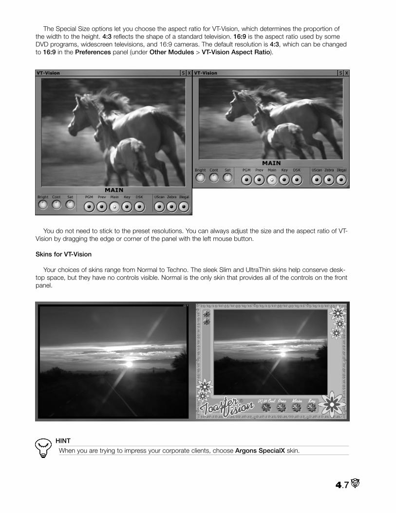
The Special Size options let you choose the aspect ratio for VT-Vision, which determines the proportion ofthe width to the height. 4:3 reflects the shape of a standard television. 16:9 is the aspect ratio used by someDVD programs, widescreen televisions, and 16:9 cameras. The default resolution is 4:3, which can be changedto 16:9 in the Preferences panel (under Other Modules > VT-Vision Aspect Ratio).
You do not need to stick to the preset resolutions. You can always adjust the size and the aspect ratio of VT-Vision by dragging the edge or corner of the panel with the left mouse button.
Skins for VT-Vision
Your choices of skins range from Normal to Techno. The sleek Slim and UltraThin skins help conserve desk-top space, but they have no controls visible. Normal is the only skin that provides all of the controls on the frontpanel.
HINT
When you are trying to impress your corporate clients, choose Argons SpecialX skin.
4.7

Fielding
In the Context Menu, you can activate or deactivate Fielding. These two options do not affect the actualoutput from VT [3], they determine how a signal is displayed in VT-Vision only.
4.8
Fielding On will display both fields of the video frame and may provide a better image.
Fielding Off only shows one field per frame and therefore takes less memory resources.
With Fielding On, the video image will jitter when the clip is not playing. If the flicker drives you nuts, thensave your sanity, (you’ll need it later), and opt for Fielding Off.

VT[3]’s Filebin is the location where you organize your directories by creating, deleting, and moving foldersor the files inside them. The Filebin’s graphical interface promotes quick navigation around the drives
connected to your system. To streamline your search, VT [3] provides a Hotlist feature that lets you jump directlyto your favorite folders.
The File Requester is the kissing cousin of the Filebin. The File Requester panel is not accessible from theMain Menu. It will appear during varied file operations, for example, when you right-click on any screen in VT [3]and select the Load... or Save… option from the Context Menu.
NOTE
Since the Filebin and File Requester are very similar, this chapter will refer to the Filebin. You can assumethe information applies to the File Requester. When there are differences, they will be noted.
Basic Filebin Setup11.. Open the Filebin from the Control Room section of the Main Menu. When first launched, it defaults to theMy Computer directory, which shows the hard drives available on your system. As you continue working withVT [3], the Filebin opens in the directory that you used most recently.
5.1
Chapter 5: Filebin & File Requester
Filebin File Requester

To access files from the Filebin, you double-click on the drive to display its contents. The Filebin works likeyour typical Windows file requester, it just has a more graphical look. The icons in the Filebin represent files andadditional folders.
22.. For this chapter, as a sample file, we will use the MareFoal.avi that is on the VT [3] Manual Content CD. Ifyou haven’t already transferred the content from the CD, load the CD and browse to the Clips folder.
33.. Open a second Filebin panel and browse to your hard drive array where you are storing your video clips.
NOTE
When you open the second Filebin, you may not see it because it might open right below the first oneon the desktop. Just click and drag it out of the way.
44.. Go back to the first Filebin. Hold down the Ctrl key and click on the Clips folder. Keep holding your Ctrl keyand the mouse button down and drag the folder into the second Filebin’s Work Area. You have just copied theClips folder and all of its contents onto your video drive. (For more information on copying and moving withdrag and drop, see below.)
55.. Close your first Filebin by clicking on the X in the far upper right corner of the Filebin panel.
5.2

View Modes
You can choose the way that the Filebin depicts the files and folders by clicking on the down arrow next tothe entry box to the right of the New Folder button and selecting your preferred View Mode.
The default view is the Large Icon mode. For those who like a big dis-play that’s easy to read, this view is for you. Your drives and files areshown with 3D icons, and your video clips boast animated icons (seebelow). Also, the name of the file is displayed.
The Small Icon mode displays the files as icons, but much smaller than in Large Icon mode – a good choiceif you want to see a large group of files in a directory.
As the Name Only mode implies - just the file name without any icons is displayed.
The Icon Only mode shows files with the icon only, without any information about the file.
The Details Icon mode displays a small icon along with categories for Name with Extension, File Type,and Modified (the date and time when the file was last modified).
The Details Only mode shows the above details without the icon.
5.3

File Properties Panel
No matter which view you select, you can reveal more details that VT [3] has acquired about a file or folderby right-clicking on it. From the Context Menu, under File, select Properties.
In the File Properties panel, the type and amount of informationdiffers depending on the kind of file (still image, audio or video), andhow it was captured. Common information includes the drive anddirectory where the file is located, the file Alias, the date the filewas created, modified, and last accessed, and the file size.
You cannot modify some of these categories. Others, like ColorTint, you can change, which can be beneficial in organizing andstreamlining your workflow.
5.4

11.. Open the Filebin if you have closed it, and open the Clips folder. Right-click on the MareFoal.avi file. Fromthe Context Menu, under File, select Properties. You can see that this avi file contains a lot more informationthan a still image would.
To Rename a File
22.. Renaming is simple. In the Filename field, just click and drag on the part of the name you wish to change,highlighting it in blue, and then type in a new name. You must click on the Apply button for this change to takeplace. In this case, don’t rename MareFoal.avi, so we don’t get confused later on.
To Color-Code a File
33.. Color-coding a file helps you pick it out in a crowd. Click on the box to the right of Color Tint to open up theColor Picker panel. (You can read more about the Color Picker in Chapter 14.) For now, pick and click a colorswatch from the choices on the upper left of the panel. That color will fill the Color Tint box. You can now Xthe Color Picker to close it. You could color-code files based on their project or your prevailing mood.
Alias
44.. Giving a file an Alias can help you track and organize your files. You can give a file a simple name for identifi-cation, much as you specify a descriptive name in the Hotlist. Throughout VT [3], all panels can access your fileby this Alias.
In the Alias field, enter a name for your file. When you click on the Apply button, the Alias is assigned to yourfile.
5.5

Adding Special Categories
55.. At the bottom of the File Properties panel, click on the Add button, and a menu of special categories popsup. If you add any of them to your file, the information that you enter into the category is accessible by otherpanels like the Spreadsheet in VT-Edit.
For example, add a Memo Field, name it Camera, and in thefield, type in Jim 1. Then add a Color field, title it Background andpick a color with the Eyedropper from the grass background. Todelete a field, click on the vertical line that divides the field title fromthe field data, and click Delete. When you have finished exploring,Close the File Properties panel.
Customizing the Filebin
You can change the interface of the Filebin to reveal the information about the files and folders that youwould find in the Files Properties panel.
11.. Be sure the folder with the clips is open in your Filebin. Switch to Details Icon mode. Click and drag the bot-tom right corner down and out to the right to expand the Filebin panel. You should see some dark gray spacenext to the Modified column.
22.. Right-click in that space and an Insert Column menu will pop up. Notice that the Camera and Backgroundcategories that you added are in the list. Click on Camera to insert as a column in the Filebin.
33.. Since we have File Type as a column, right-click on Name with Extension, and replace it with Name w/oExtension.
5.6

Sorting Files
If you click on a category heading, like Modified, you will activate a sorting function. Click once and a down-ward pointing arrow appears, indicating the files will be sorted in descending order. In the case of Modified, theoldest first and the most recent last.
Click again and the arrow points up; and the files are now sorted in ascending order. For a category likeName, the files are ordered alphabetically starting with Z and ending with 1.
You can only sort by one category at a time.
Animated Icons
In VT [3], video clip files employ animated icons. When you hover the mouse over a video icon, the videoplays in the icon and a box pops up that displays the current frame and the clip length. For added control:
• Hold Shift during a rollover preview to fast forward at 10x speed. You can speed ahead to scenes in the clip, and then release the Shift key to return to viewing them at normal speed. • Hold Alt during rollover preview to play backwards. • Hold Alt + Shift to play backwards at 10x speed.
In the Preferences panel (Files > Rollover Animated Previews), you can turn off icon animation – a goodidea if you are trying to conserve system resources. You also can turn off the current frame and clip length dis-play if you feel the info takes up too much screen real estate (Files > Rollover Time Code and Length). SeeChapter 3 for more information on the Preferences panel.
Default Icons
Default icons represent other files and folders.The familiar yellow folder represents a directory.Files that can be played and edited in VT [3]may appear as film reels or as thumbnails of aframe from the video. Still image files that youcan insert into projects, such as bmp, jpg, andtif, appear as thumbnails of the actual image.
The icons for DVEs also are animated. The icondepicts a still concept of the DVE action. Butwhen you hover the mouse cursor over the icon,you will see the DVE make a transition from acolorful VT1 foreground to a VT2 background.
Play from the Filebin
Double-click on a video or audio file in the Filebin, and you launch QuickPlay, which is a mini digital disk viewer.If the Switcher is closed, the QuickPlay clip is automatically loaded into Program Out and you can view or listen toyour file on a VT-Vision set to PGM. (If the Switcher is open, QuickPlay is put into the Preview bus, therefore setVT-Vision to Prev.)
The QuickPlay interface provides the basic Stop, Play, Rewind and Fast Forward buttons. It also includes a Jogwheel. During playback, it displays elapsed time, clip length, and a stereo VU audio meter. If you have audio, youcan mute it by clicking the Speaker button. To continually loop the clip, highlight the Curved Arrow button.
5.7

The QuickPlay holds only one file for playback. To stop playing and to close the QuickPlay panel, just clickanywhere on the desktop.
NOTE
Sometimes, (especially when you are in the Name Only view), the double-click can be tricky to master.If you don’t have the right rhythm, often the computer aliens think you are trying to rename a file with theclick-pause-click technique. If you can’t syncopate to the alien beat, change to one of the icon views, anddo the double-click tap dance on the little pictures.
Navigating If you’re familiar with a Web browser, then you’ll be comfortable with the navigation buttons on the Filebin.
As you navigate through the Filebin, VT [3] keeps track of the steps you have taken. The Back buttonretraces the route moving you back one step each time you click it. The Forward button only works if you haveused the Back button, and it moves you forward to the location that the Back action just left.
Filebin Shortcuts
• Backspace: Go up one folder• Shift + Backspace: Return to the folder from whence you came.
Editing
With the buttons at the top of the panel, you can cut, copy, paste, and delete folders and files. To use thesebuttons, choose a folder or file, and click on the editing action.
• Cut will copy the file or folder to the clipboard and removes it from the current directory.
• Copy will copy the file or folder to the clipboard and leaves a copy in the current directory.
• Paste works with Cut and Copy. Paste places that file or folder from the clipboard into the directory that you choose.
• Delete will delete a file or folder from the current directory and from your hard drive.
5.8
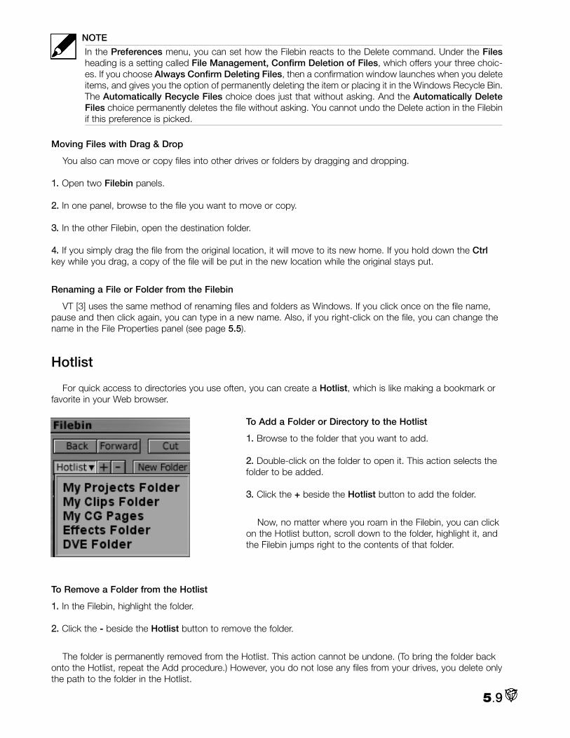
NOTE
In the Preferences menu, you can set how the Filebin reacts to the Delete command. Under the Filesheading is a setting called File Management, Confirm Deletion of Files, which offers your three choic-es. If you choose Always Confirm Deleting Files, then a confirmation window launches when you deleteitems, and gives you the option of permanently deleting the item or placing it in the Windows Recycle Bin.The Automatically Recycle Files choice does just that without asking. And the Automatically DeleteFiles choice permanently deletes the file without asking. You cannot undo the Delete action in the Filebinif this preference is picked.
Moving Files with Drag & Drop
You also can move or copy files into other drives or folders by dragging and dropping.
11.. Open two Filebin panels.
22.. In one panel, browse to the file you want to move or copy.
33.. In the other Filebin, open the destination folder.
44.. If you simply drag the file from the original location, it will move to its new home. If you hold down the Ctrlkey while you drag, a copy of the file will be put in the new location while the original stays put.
Renaming a File or Folder from the Filebin
VT [3] uses the same method of renaming files and folders as Windows. If you click once on the file name,pause and then click again, you can type in a new name. Also, if you right-click on the file, you can change thename in the File Properties panel (see page 5.5).
Hotlist
For quick access to directories you use often, you can create a Hotlist, which is like making a bookmark orfavorite in your Web browser.
To Add a Folder or Directory to the Hotlist
11.. Browse to the folder that you want to add.
22.. Double-click on the folder to open it. This action selects thefolder to be added.
33.. Click the + beside the Hotlist button to add the folder.
Now, no matter where you roam in the Filebin, you can clickon the Hotlist button, scroll down to the folder, highlight it, andthe Filebin jumps right to the contents of that folder.
To Remove a Folder from the Hotlist
11.. In the Filebin, highlight the folder.
22.. Click the - beside the Hotlist button to remove the folder.
The folder is permanently removed from the Hotlist. This action cannot be undone. (To bring the folder backonto the Hotlist, repeat the Add procedure.) However, you do not lose any files from your drives, you delete onlythe path to the folder in the Hotlist.
5.9

In VT [3] you can give a meaningful name to the paths you add to the Hotlist by using the Alias property. Forexample, you can name a directory full of wav files “Music” in the Hotlist.
To Give an Alias to a Hotlist Item
11.. Select the folder that you want to name with an Alias.
22.. Right-click on the folder and choose Folder > Properties.
33.. In the Alias field of the Properties panel, enter a name for your folder. Then click on the Apply button. TheAlias is now assigned to your folder; and the Alias now replaces the folder name in the Hotlist.
Adding a New Folder
11.. To add a new empty folder to your Filebin, browse to the desired location and highlight the hard drive or fold-er where you want the new folder.
22.. Click the New Folder button and a little requester panel pops up. Type in the name of the folder, hit Enter,and the folder will be added.
If you highlight an existing folder or file before you click on the New Folderbutton, that item(s) will be placed inside the new folder when it is created.
Filebin Context MenuDifferent Context Menus, (depending on whether you have a file selected or not), are accessed by right-click-
ing in an open area of the Filebin panel. If a file or folder is not selected, the Context Menu offers you layoutmanagement tools and housekeeping options related to the NewTek Info folders, (that despite what some peo-ple believe, do not multiply like lascivious leverets).
For example, under Filebin Tools, if you click the Clean Up Missing Files tool, VT [3] tries to match theNewTek Info file with its associated file. If it can’t find the file, it deletes the NewTek Info file. Orphaned NewTekInfo files occur when you delete the companion file in Windows.
Clean up temporary files will remove all the files that VT [3] gener-ates, which will be regenerated when needed, for instance audio peaklevels, icon files, etc... It does not delete files that are valuable and notautomatically regenerated like asset management files. This proecdure ishelpful if you have modified many clips in another program, and you wishto update all the icons.
Set Directory Path is a navigational tool for those who like to type. Ifyou click it, a dialog box pops up where you can enter a new path for theFilebin. For example, if you enter D:, the Filebin will jump to the root ofyour D drive. If you enter C:\Winnt, you will enter your system folder.
With a file or folder selected, in addition to these Filebin options, you’llfind common file management and clipboard options, like Open, Cut,Copy, and Delete.
Render from the Filebin
You can render files in the Filebin to make a group of clips into oneAVI, RTV, or other video file. Select the clips that you want to render,right-click to open the Context Menu, and under A/V Clips, chooseRender/Convert... The Render panel launches and you choose yourcodecs and resolution. For more information about the Render panel, seeChapter 7.
5.10

T he Deck Control panel is a software interface with deck controls that allows you to tell a video tape deck ora camera attached to VT [3] to play, stop, fast forward, rewind and pause. With Deck Control, you also can
jog and shuttle most decks.
BASIC SETUP1. Your first task is to connect your deck or camera so that VT [3] can talk to it. There are two basic connectionmethods, IEEE1394 (FireWire) and RS422.
Digital Video (DV) Connection)
If you have a DV camera or deck, you will need to install an IEEE1394 (FireWire) card in your computer if itdoesn’t have a built-in connector. VT [3] will automatically recognize when a DV source is active.
RS422The RS422 protocol is used to connect a deck like a BetacamSP to VT [3]. If you don’t have an SX-8, you
need to attach the deck directly to one of your computer’s serial ports with a special RS-232-to-RS-422 cable.
NOTE
You can purchase the cable at various online sites. Addenda Electronics version is called the RosettaStone RS-2/3.
6.1
Chapter 6: Deck Control

For a BetacamSP deck, you attach the cable to the Remote connector on the back of the machine. Otherdecks will vary; you need to check their documentation for specific instructions.
NOTE
If your deck doesn’t have an RS-422 port, then call NewTek’s Technical Support and they will try to assistyou.
If you have an SX-8, you still can use the direct deck-to-serial-port method, or you can plug a cable from thedeck into one of the SX-8 VTR inputs on the top right of the box.
To connect an RS-422 deck to the SX-8, simply use a straight 9-pin serialcable from the deck to one of the three RS-422 connectors, labeled VTR onthe SX-8. Then attach another standard 9-pin serial cable from the SX-8 Serialconnector to one of the computer 9-pin serial connections. Basically, the sig-nal gets routed internally in the SX-8 from the VTR input to the Serial connec-tor.
NOTE
This SX-8 to computer cable is not quite standard because one end ismale and the other is female.
And remember all this cabling is just for transferring deck control signals.You still will have to connect separate audio and video cables to your deck.
2. Once you get all the cables straightened out, turn on your deck. Now,you’re ready to go inside VT [3].
3. Load Deck Control from the Control Room section of the Main Menu.
Adding a New DV Deck
1. Click the arrow next to the Source Preset window and choose Add New Deck.
2. Click in the Source Preset Name window and give your deck a name.
3. Next, click in the Type window and select DV and Other.
4. Click in the Source window and choose Microsoft DV Camera and VCR.
6.2

NOTE
You will not see this option if your DV deck is not connected or turned on.
5. After selecting the DV Source, the Deck is Connected To window should say DV. Hit Add. If you have arecorded tape in the deck, you should see its Timecode displayed in the Deck Control panel. If you do, yourdeck is set up.
Adding a New RS-422 Deck1. Click the arrow next to the Source Preset window and choose Add New Deck.
2. Click in the Source Preset Name window and give your deck a name.
6.3

3. Next, click in the Type window and select RS-422 Deck Control.
4. Click in the Source window and choose from the long list. If you made the deck-direct-to-computer connec-tion, then you pick from the four RS-422 on COM choices.
Most computers have two external serial ports, COM1 and COM2. If you don’t know which one you pluggedinto, guess RS-422 on COM1. If you are wrong, you’ll receive an ERROR. Could not connect! message in theDeck Control panel. Then try COM2. (COM3 and 4 are listed if you have other devices such as modems occu-pying COM1 and 2.)
If you connected your RS-422 deck through the SX-8, note which SX-8 VTR connection you used. They arenumbered from the top down. So if you plugged into the top VTR connector and COM1, you would pick BOBRS422-1 on COM1. When the connection is made, and if you have a recorded tape in the deck, timecodeshould appear in the Deck Control panel.
6.4

5. You will need to tell VT [3] to which video input the deck is connected by finding it in the Deck is ConnectedTo list.
6. Hit Add and your deck is setup.
DECK CONTROLSThis panel comes with the standard deck controls: Play, Rewind, Fast Forward, Stop, and Record, most ofwhich are depicted by icons on buttons. When you click a button, it highlights and engages your deck.
NOTE
The deck controls on VT [3] can only be as responsive as the attached deck or camera. If the device isnot inherently capable of certain functions, the VT [3] buttons will not work.
WARNING
This is a big warning, especially after you have used VT [3] for awhile. The Record button on this panelwill activate the Record function on your deck. It does not, repeat, does not, take you to the Capturepanel. As a standard precaution, you always should engage the record inhibitor tab or button on yourrecorded videotapes. Then if by mistake you hit this Record button, your tape is safe.
Control Buttons
Rewind (See page 6.6.)
Stop tells the external device to stop its current action.
Pause will pause the device on the current frame.
Play
Fast Forward (See page 6.6.)
Single Frame Forward (See page 6.6.)
6.5

Single Frame Reverse (See below for details.)
Cue waits for an external signal to play the deck. (See below for details.)
Fast Forward/Rewind/Shuttle
If you are playing a tape and press Fast Forward, the deck will jump into shuttle mode and show youimages as you fast forward the tape. If you are stopped and press Fast Forward, the tape will Fast Forwardwithout engaging the playback heads, so you will not see images. (This saves your deck’s tape heads fromexcess wear and tear.) Rewind works in the same manner, just in the opposite direction.
Single Frame Forward and Reverse
The Single Frame buttons will advance or reverse the tape one frame at a time. If you click once on this but-ton when the deck is playing, the machine begins playing back at about five frames per second. If you double-click it, it will pause the machine, the next time you click it, the machine will advance a single frame and pause.To return to normal speed, click the Pause button off or hit the Play button. You also can hit a Single Framebutton when the machine is stopped and it will start playing at the five frames per second rate.
Shuttle & Jog
When you use the Rewind and Fast Forward buttons, the playback head on the deck disengages and youhave no visual reference. If you want to see as you move quickly through a tape, use the wheel to the left of thedeck controls, which will shuttle or jog through your video. The Shuttle option lets you quickly scan forward orbackward through your tape. The Jog option lets you scan forward and backward through the tape with frame-by-frame accuracy. These options play both video and audio.
NOTE
Once again, Jog and Shuttle are only as good as the deckthey are controlling, or in certain cases, what the deck willallow from an external controller.
The LEDs below the knob are Shuttle/Jog speed indicators, each representing an incremental change inspeed. You also can click the LEDs and play back clips. The LEDs near the center give you playback in slowmotion, while LEDs at the ends play back at high speed. Click the LEDs on the right side to play forward; onthe left to play in reverse.
CueThe Cue button waits for a signal from the Switcher and plays the deck when the signal is received. Cue
works with the Pause button.
To Cue the Deck Control
1. Find the starting point on the tape and click on the Pause button. Pause and Play both illuminate.
2. Click on the Cue button.
3. Right click on the Input window and select Put onto Preview In.
4. Now, on the Switcher, click Auto to transition between your Main source and the Preview source with the
6.6

cued deck. As soon as the switch occurs, the deck begins playing automatically and you will see it on the VT-Vision set to PGM.
5. Switch between Main and Preview again. When the deck input source returns to the Preview bus, the deckpauses and awaits a further prompt from the Switcher.
Timecode
The timecode display above the deck controls shows you the duration of the video. You receive the timecodefrom the external device, so timecode plays when you play the device and it stops when you stop the device.Also you can use the device timecode as a reference for specific scenes at a known time.
Capture PanelIf you click on the C to the right of your Source Preset window, you will bring up the Source Preset panel. If
your deck is a DV type, the Capture Properties button will be grayed out because you can only capture a DVstream through the FireWire cable.
If you have an RS-422 type, then click on the Capture Properties button to open up the panel, which allowsyou to create several different configurations for a single deck. For example, you may make a “compressed”configuration for your Betacam deck when you need to capture a large amount of offline, or draft-qualityfootage for rough cuts. You then can simply load up the “uncompressed” configuration when you are ready toacquire your final edit decision list for high-quality capture and playback.
Advanced PanelAt the bottom of the Source Preset panel, click on the Advanced button. The menu provides you with controlsthat will adjust how the Jog knob interacts with your deck. Unless you are a mechanical engineer, we stronglysuggest that you close the panel, thank you. If you must fiddle, remember, if it ain’t broke don’t fix it. And asalways, if you break it, you buy it.
6.7

Context Menu
Right-clicking on an empty area of the Deck Control panel brings up the Context Menu where you can Saveand Load panel configurations. and exit the module. For more information on saving configurations, seeChapter 3.
Import & Export Presets
In the Context Menu are tools for Importing and Exporting Presets. If you click on Import Presets, a FileRequester will open by default to VT3\UserData\DefaultUser\CaptureDevice\Presets. Inside there are Presets forgeneric Betacam, DV, U-matic, Hi-8, and VHS decks. Click on the one that applies to your type of deck and hitOpen. The Presets will set the plug-in and the Advanced settings of the deck, so you need not go in there. Youstill will need to establish the connection with the deck, as usual, by selecting the Source.
6.8

Capture is the process of transferring your input from sources such as cameras and tapes to your comput-er’s hard drives. VT [3] provides two methods for acquiring material: manual capture and batch capture.
Both involve attaching your camera or deck to VT [3], choosing some recording settings and formats, and thenrecording to the hard drives.
Manual capture is the more fundamental of the two and is the only procedure for capturing live video fromcameras. Batch capturing is a powerful technique that controls a video deck and captures exact locations onthe tape according to timecodes that you specify – allowing you to capture clips in batches. The two tech-niques have their own panels in VT [3].
CAPTURE PANELTo manually capture a clip, you use the Capture panel.
Capturing Video and Audio in the Capture Panel1. From the Main Menu, under Control Room, select Capture.
2. To begin capturing, youneed to connect your cam-era or video deck to VT [3]. (Connecting equipment isdiscussed in Chapters 1and 2.)
If you are controlling yourdeck within VT [3], you alsowill need to open the DeckControl panel. (See Chapter6.)
3. At the bottom of theCapture panel are threetabs: Format, Options, andRecord. When you begin acapture session, it’s a goodpractice to review every tabto ensure that your settingsare all correct.
7.1
Chapter 7: Capture & Batch

FORMATVT [3] can record clips in a wide variety of formats. You select which video and audio codecs you will use
from the Format panel.
4. Click on the Format tab. The first task is choosing the video codec.
NOTE
If you are capturing DV through a FireWire card, you see the Format panel is not available because, inessence, you are simply transferring the digital file from your tape to the hard drives.
If you are capturing DV through the S-Video or Video Output on the camera or deck, then you are dealingwith an analog source. The Format panel would be available and you would need to choose a codec.
Video Codecs
5. Click the arrow next to the Video Codec box. The drop down menu lists different video encoders available onyour system.
By default, VT [3] saves files in the uncom-pressed NewTek RTV format. If you are stream-ing video on the Internet, you would chooseWMV WindowsMedia Streaming File. The nextgroup of formats refer to uncompressed videoand different color space schemes. Colorspace schemes refer to how pixels are orderedwhen you digitize your video input. Below thatare compressed video formats.
RTV and WMV
• NewTek RTV file: 4:2:2 color (NTSC) 4:2:2(PAL). Supports 480, 486, and 576 line cap-ture. Captures only at full resolutions: 720x480,720x486 and 720x576 (PAL) at full frame rate(29.97 fps for NTSC, 25 fps for PAL). VT [3]proprietary format for editing; saves file in RTVformat.
• WMV WindowsMedia Streaming File(video): 4:2:0 color. Progressive or streaming;scalable; must use Windows Media Player forplayback. Used for Web distribution. (Older ver-sions of Windows Media files used the .asfextension.) Half resolution at half frame rate isrecommended.
7.2

AVI Options
When you select the AVI format, you save your video file as an AVI, and the compression scheme is deter-mined by the encoder you select. If you install the appropriate codecs, you also can capture files in other for-mats, such as streaming media or MJPEGs.
The first group of options under AVI Video Compression Type give you uncompressed video:
• Uncompressed (UYVY): The recommended format for uncompressed AVI files.
• Uncompressed (YUY2): Used when UYVY gives unsatisfactory results.
• Uncompressed (BGR24): Uses 24-bit color; used only when unable to use UYVY or YUY2; (this option usessignificantly more CPU resources to capture than the UYVY and YUY2 options).
• Uncompressed (BGR32): Uses 32-bit color; see BGR24.
The remaining codecs are determined by what you have installed on your system. The codecs outlinedbelow are defaults for Windows Media Player, which is installed when you install VT [3]. For more information onthese formats, visit the Web sites for Microsoft, QuickTime, Intel, and Cinepak.
• DV Video with interleaved DV Audio: 4:1:1 color for NTSC (4:2:0 PAL); audio. Typically used for editing, notfor distribution. Type 1 DV format uses DV audio and DV video streams to create AVI format; (some softwarewill not read this kind of AVI). Strongly recommend using 720x480(NTSC) or 720x576(PAL).
• WMVideo Encoder DMO (Windows Media Video Encoder): Enhanced version of Windows Media encoderfor extremely high bit rates and connections (250-750 kbps). Used for downloadable movies. Rarely used.
• MSScreen Encoder DMO: Rarely used.
• DV Video Encoder: 4:1:1 color for NTSC (4:2:0 PAL); audio. Typically used for editing, not for distribution.Type 2 DV format uses DV video only so that you can choose uncompressed audio to create an AVI. Stronglyrecommend using 720x480 (NTSC) or 720x576 (PAL).
• Indeo® Video 5.10 Compression Filter: YUV-9 color; progressive or streaming; scalable; supports trans-parency. Must use 480 or 240 lines – does not work with 486 or 243. Used for Web distribution. (This is a slowcodec and is unlikely to work with full resolution. To use this codec you must drop the frame rate and the reso-lution.)
• MJPEG Compressor: 4:2:0 color. Used for editing and archiving, not for final delivery. (This codec is CPUintensive. You can find free MJPEG codecs at www.mjpeg.com that work in real-time.)
• Cinepak Codec by Radius: 16-bit color. Plays on older computers. It is commonly used for hard drive orCD-ROM playback.
• Intel Indeo Video 4.2:0 Video V2.50
• Intel Indeo Video R3.2: 16-bit color. Plays on slower computers with Windows Media Player. Inappropriatefor Web, used for playback on hard drive or CD-ROM; commonly used format.
• Intel Indeo Video 4.5
• Indeo Video 5.10: Similar to Indeo Video 5.10 Compression Filter. Try substituting this codec if theCompression Filter gives inadequate results.
• Intel IYUV codec
• Microsoft H.261 Video Codec: 4:2:0 color. Videoconferencing codec used for slower connections (128-384Kbits).
7.3

• Microsoft H.263 Video Codec: Same as above, but better quality video conferencing codec with motioncompensation.
• Microsoft RLE (Run-length encoded): 32-bit color. Plays on slower computers; for hard drive or CD-ROMplayback. (Not a great option for video, but supported on Windows 3.1.)
• Microsoft Video 1: 32-bit color. Plays on slower computers; for hard drive or CD-ROM playback. (Not really agreat option for video, but supported on Windows 3.1.)
• NewTek VT [3] Video Codec: Allows you to generate, load and save RTV files to and from any applicationthat supports AVIs. This is the AVI wrapper codec used within VT-Edit and is always uncompressed and full res-olution.
6. Click on the C (Configure) button, (next to the arrow), to automatically configure the codecs with their opti-mized settings.
With some of the codecs, like WMV WindowsMedia Streaming File, clicking the C button will pop up a panelof configuration options.
Audio Codecs
7. Next, you need to specify your audio codec. Clicking on the arrow will bring up the Audio Codec menu,which lists the available audio encoders that you have installed on your system. Those outlined on the nextpage are defaults that ship with VT [3].
When you capture audio and video together, you can save it as RTV or AVI. In the RTV format, you capture aseparated WAV audio file that is stored in the same folder as your video file with the same prefix name. In theAVI format, audio also can be stored embedded within your file. When you capture only audio, it is saved as aWAV file by default.
7.4

These audio codecs will offer you different rates for sampling frequency, different bit sizes, and a choice ofmono or stereo. These options determine the final size and quality of your file. Uncompressed audio is usuallysampled at 44.1 KHz, 16-bits, stereo.
• RTV: VT [3] proprietary format used with RTV video format.
• WMV WindowsMedia Streaming File (audio): Used with Windows Media. Best for low bit rate music; mustuse when you choose Windows Media encoder for video.
• Uncompressed PCM: Uncompressed Pulse Code Modulated audio. Use with uncompressed video at highbit rates.
• WM Audio Encoder DMO: Enhanced version of Windows Media audio encoder for extremely high bit ratesand connections (250-750 kbps). Used for downloadable movies.
• IAC2: 8:1 compression. Intended for use with Indeo 5.10 video codec.
• IMA ADPCM International Multimedia Association: 4:1 compression for multimedia. Not suited for Web; lossycompression. Used with QuickTime and Video for Windows.
• PCM: Pulse Code Modulated audio for voice encoding. Will quantize audio.
• Microsoft ADPCM Microsoft Adaptive Differential Pulse Code Modulation: 4:1 compression rate. Best usedwith high bit rate video; often used for multimedia CDs.
• ACELP.net Algebraic Code-Excited Linear-Prediction: Best for low bit rate voice recordings. Used for multi-media.
• DSP Group TrueSpeech™: You probably guessed that this codec is optimized for voices. Suited especiallyover a modem or network. Compresses all sound to 1-bit.
• Windows Media Audio V1: Older version of Windows Media Audio.
• Windows Media Audio V2: Older version of Windows Media Audio.
• GSM 6.10: Low level audio for speech compression.
• Microsoft G.723.1: Low bit rate for video conferencing. Not good for music or special effects; createsstreaming audio.
• CCITT A-Law: 2:1 compression. Used for telephony in Europe.
• CCITT µ-Law: 2:1 compression. Used for telephony in United States and Japan; general audio for Unix plat-form.
• MPEG Layer-3 MP3: Used primarily for music; near CD-quality. Common for Web distribution for progressivedownloads, not suitable for streaming.
Clicking the C button automatically configures the codecs with optimized settings.
Occasionally, when you pick a video codec, the audio codec will be selected automatically by VT [3]. Manyof the video and audio codecs cannot be combined. Please refer to the Table of Video and Audio CodecCombinations to see the recommended audio and video codec combinations.
7.5

7.6
RReeccoommmmeennddeeddMMaayy aallssoo wwoorrkk*
xx

FormatIn the Format option, you select the resolution of the clip that you will be recording, measured in pixels.
Some codecs do not work with certain resolutions. The Capture panel will warn you if your settings are suspectby displaying an Invalid Settings message. For example, the Indeo Video 5.10 Compression Filter will not workwith a 720x486 resolution; you must use 720x480.
8. Next, you need to specify your Format resolution for the clip you are recording. Clicking on the arrow willbring up the available resolutions.
Interlaced Formats
Interlaced formats use fields for video output. One field contains the odd lines of the video frame and theother contains the even lines of a video frame. Two fields make one frame of video. Interlaced formats are usedfor television and video distribution.
7.7

Progressive Formats
Progressive formats refer to formats that do not use separate fields for video output. Progressive formats areused for computer, DVD, and Web distribution, and are an excellent format for time-stretching. The Capturepanel does a quality de-interlace from your interlaced cameras and creates video that you can assign asfootage for digital programs like LightWave. You can use a progressive format for effects like slow motion video.
Frames per Second
FPS stands for Frames Per Second, and it indicates the speed of your video. For all of these formats, youcan choose between 29.97 fps or 14.98 fps (NTSC).
OptionsUnder the Options tab, you have a number of decisions to make about what source you will record, if it is
timed, and if you will capture audio or video or both.
Input
9. You need to pick your source from the Input drop down menu. Basically, you are picking the source’s loca-tion in VT [3].
NOTE
If you have an SX-8, your list will be a lot longer because you have more input sources available.
For example, let’s say that you don’t have an SX-8 and your BetaSP deck is plugged into the Componentinput. Then, in the menu, under Select Analog Sources onto Main In, you would pick Component. VT [3] willroute Component to Main In.
7.8

If you are capturing DV through a FireWire card, you would select Microsoft DV Camera and VCR.Remember, you need to have your DV deck or camera plugged in and turned on to see this choice in themenu.
You also can simply pick Main In or Preview In. When you choose Main In, you can capture video directlyfrom the source that you have routed to Main In. If you choose Preview, you capture the source that sits on thePreview bus in the Switcher.
If you choose Program Out, you capture the events that occur when you use the Switcher, including anyfades or DVEs or Downstream Keys. You would pick Program Out if you wanted to capture a live switch. (Formore information on the Switcher and Program Out, see Chapter 9.)
Video and Audio
10. The Video and Audio check boxes let you choose whether to capture both video and audio simultaneously.If you uncheck one of these boxes, you capture only video or only audio.
Timed
11. The Timed option lets you set a specific time limit for capturing your video. When the Timed box is check-marked, you can set the capture time limit in hours:minutes:seconds.frames in the first field, or you can set itjust by frames in the second field. These two fields are linked, so changing one updates the other.
You use Timed when you want to capture an event and you know how long that event will run. For example,if you wanted to capture from a camera for 15 minutes, you can set the Timed option to 15:00:00, hit Recordand walk away. VT [3] will stop recording after 15 minutes.
Recording Single Frames
One common use of the Timed option is to capture a still image. You set Timed to one frame (00:00:00:01).In the Format menu, pick a Progressive resolution, like 720x486 Progressive, NTSC. Now every time you clickRecord, it captures one frame, de-interlaces it and saves it. De-interlacing will eliminate the jitter inherent ininterlaced video still frames that are displaying both fields.
Time Lapse
12. To create time-lapse photography, such as a flower opening, you use the Time Lapse option, which cap-tures a frame of video at specific intervals. So if you enter 00:00:05:00, you tell VT [3] to capture one frame ofvideo every five seconds.
Now, if you also have Timed checked, then VT [3] will capture the number of frames specified in the Timedfield. For example, if Timed was set to 2 minutes, it would capture 3600 frames of video (120 x 30 fps NTSC). Ifyou have Time Lapse set to record one frame every minute, you will be recording that flower for 60 hours andend up with two minutes of video.
Stop When Frames Drop
13. When checkmarked, this option will stop capturing video if VT [3] ever drops frames during capture.Activate this option when you capture video from a tape so that you know if you’ve lost frames. If VT [3] dropsframes, it may indicate that your hard drive can’t maintain a fast enough data transfer rate to record video.
7.9

Deactivate this option when you capture a live event, so that you don’t stop recording at a critical point.
Pause When Recording Stops
14. This choice pauses the capture event and when you begin recording again, you record to the same clip(whereas when you Stop, you record to an entirely new clip the next time you record).
RecordIn the Record panel, your two main tasks are file management and deck control.
File Naming and File Location
15. You need to name your file and specify its location. If you are especially nimble or if your clips are long, youcan actually name your files as you are capturing them. For the novices and maladroits, it’s prudent to do thesechores before you hit the Record button.
The top portion of the Capture panel looks and works like the File Bin. When you click on the drive and thefolder where you want to place your clip, that information will appear in the Path box in the Record panel. (If youneed to create a new folder, click the New Folder button.) Now, in Name box, enter the name of the clip.
You can record a series of clips without naming every one. VT [3] will append a numeric identification toeach file. For example, if you name a clip Horseplay, VT [3] will automatically increment the name with a number
7.10

for each successive clip. So the next clip would be named Horseplay002.
NOTE
You can change the naming scheme in the Preferences menu under Files > Files Naming.
Record Controls
16. After you have chosen your settings, identified your source, named your file and chosen a directory, you canbegin to capture.
RECORD
The red RECORD button on the far right is the key to the kingdom. You hit it to capture your video. The key-board shortcut is Enter.
STOP
If you have not set any specifics about timing, (as discussed previously), you stop capturing video by clickingthe STOP button. The keyboard shortcut is Enter.
Pause
Pause halts your capture. When you click Pause again, you begin recording to the same clip. The keyboardshortcut is the Spacebar.
Reset
Reset allows you to clear a current recording and start recording right away. This option is great if you havefalse starts. The muffed beginning is deleted, but the file name stays the same. And VT [3] automatically beginsrecording your file at the frame where you hit Reset. The keyboard shortcut is Delete (while recording is active).
Chop
Chop allows you to stop recording to one clip and begin recording immediately to a new clip. You can usethis option to break down one large video into a group of smaller clips; or if you record a live event, to break itinto separate clips. Basically, you hit Chop each time you want to end a clip. VT [3] then immediately startscapturing a new one using the numeric name scheme discussed in File Naming above. The keyboard shortcutis Backspace.
Chop works best with uncompressed formats, because you miss fewer frames between chops. When youuse a compressed format for capture, you lose some frames when you chop because the computer mustprocess the compression algorithm each time it begins recording again.
When you capture video, VT [3] saves the file properties that you choose: resolution, frame rate, codec, pro-gressive or not, timed settings, number of frames recorded, length recorded, and so on. You can access thisinformation by right-clicking on a recorded file and selecting File Properties.
Audio Level
While you are capturing, you can adjust the volume of your audio with the knob next to the VU meters on theright of the Capture panel. Turning the knob clockwise increases volume and turning it counterclockwisedecreases volume.
You also can adjust volume in the Audio Mixer, but the Capture panel’s volume adjustments are applied asthe last step before writing to disk.
7.11

Volume Units Meter (VU)
Your goal when recording audio is to keep the level strong enough to produce a good signal, but not sostrong that the audio is distorted (known as overmodulation). On VT [3]’s VU meter, that level is typically in theyellow zone. Green indicates a signal is coming into the channel. Normally, you would raise that volume’s chan-nel until you see the louder portions range in the yellow.
If the VU meter doesn’t move, and you intend to capture audio, it’s a good indicator that your Audio Mixer isnot set up right or your audio input is not working. (For more on the Audio Mixer, VU meters and volume levels,see Chapter 10.).
Drive Space
The Drive Space display monitors your hard drive; the progress meter shows the hard drive filling while youcapture. If you keep your eye on the hard drive meter, you’ll know when you have no more space available tocapture video. You should leave yourself some headroom, though, and avoid cramming up your entire videodrive. Of course, if you see the hard drive filling, you can go into the Filebin and delete files to make more room.
NOTE
When you run out of space on your drives, Capture stops with a warning message.
Remember that one second of uncompressed video needs 22MB of hard drive space. One hour takes79.2GB. For DV, one hour uses only 12.6GB. And you can record at even higher compression rates, becauseVT [3] can record with any codec you install.
NOTE
The higher the compression, the lower the image quality and that image quality is not recoverable. If youplan to process images or video, record at the highest level that space will allow.
Timecode Display
The Timecode display tracks the length of the clip you are capturing in hours:minutes:seconds:frames. If youcalculate how much time your drive capacity allows, you can use the timecode to judge precisely when you’recreeping up on the edge of your drive space.
BATCH CAPTUREUnlike manual capturing, (where you just play your tape and hit Record when you are ready to capture),
batch capturing is a more controllable procedure that works with precise timecodes on the source tapes. Abatch capture session can be recorded and recalled later to repeat the process.
In the world of non-linear editing, there never seems to be enough hard drive space. Ultimately, you have toclear your video drives to make room for the next project. But if you have batch captured your clips, you canreproduce the capture session if you need to restore your project to make revisions.
Basic Batch Capture Setup1. From the Main Menu, in the Control Room section, load Batch Capture.
2. Since batch capturing relies on being able to communicate with and control a video deck, you begin by settingup your deck. You can do it directly in this panel by clicking on the arrow next to Source Preset in the lower left ofthe panel. The procedure also can be done in the Deck Control panel. (See Chapter 6 for detailed instructions.)
7.12

3. When you have your deck configured, load the tape. If everything is working, the Timecode display on theBatch Capture panel should be showing the timecode on the tape.
Auto Mark
4. Use the deck controls on the panel to find the beginning of the first spot on the tape that you want to cap-ture. When you see it, hit the Auto Mark button, which sets your In Point. Let the tape roll and when you seethe end point, hit the Auto Mark button again, which sets the Out Point for the clip. (You have just set your firstbatch capture points.) If you click Auto Mark a third time, you set the In Point of your next clip. And so it goes.
Mark In & Mark Out
Now, occasionally, you will click Auto Mark before you really wanted to set the In or Out Point. For example,the voice-over talent starts a take, you hit Auto Mark, and then he flubs after two sentences and starts over. Ifyou hit Mark In, it will reset the In Point. Then he flubs again. Hit Mark In again. Mark In sets a temporary InPoint that can be changed as long as you don’t move on to the next clip.
Mark Out works the same way. If you hit Auto Mark to set an Out Point and then realize that you need moreof the take, you can click on Mark Out and it will reset the Out Point. Now, the fastest way to move to settingpoints for the next clip is to click on Auto Mark.
The problem is that when you do, it resets the Out Point. If you want to keep the Out Point made with MarkOut, you need to click on an empty area of the Batch Capture panel to deselect the clip. Now, when you hitAuto Mark, it begins a new clip without changing the Out Point of the previous clip. Try it to see how it works.
Keyboard Shortcuts
If you are a two-handed batch capturer, the keyboard shortcut for Auto Mark is the Spacebar. Mark In is iand Mark Out is o.
7.13

HINT
If you press F1 in any panel, the list of keyboard shortcuts for that panel will pop up.
Batch Capture Entry Field
Look at the data that is generated when you set In and Out Points.
Tape Name
5. VT [3] puts in a default Untitled Tape Name. It’s critical that you change this to the name that you labeledyour tape. Each tape needs a unique label for Batch Capture to work efficiently. So you need to adopt a habitof titling your tapes. Batch Capture is relying on you to feed it the proper tape. If you don’t it will merrily go oncapturing clips according to the timecode, oblivious to the fact that the tape is of your daughter’s birthdayinstead of the malpractice deposition.
You edit the Tape Name by clicking once in the field and start typing. The original name will be replaced bythe new one. When you are finished, click in an empty area of the Batch Capture panel. If you hit Enter aftertyping, a new entry will be generated. This facilitates typing in a Batch Capture list, which is discussed below.
You also can right-click in field, choose Edit Tape Name from the Context Menu, and type in a new name.
HINT
If you want to change a number of entries to the same name, Shift-click or Ctrl-click to select them.Then when you type a new name, it will change the name for all the entries.
Capturing from Multiple Tapes
If you have clips to capture from more than one tape, the procedure is the same. You just put the new tapein the deck and continue setting In and Out Points. Again, it’s essential to put the new tape name in the BatchCapture list. When it comes time to perform your batch capturing, VT [3] will cue you to insert the new tape.
Editing In, Out, and Duration
The In Point, Out Point, and Duration fields can all be edited the same way: Click, type in a new value andclick in an empty area of the panel. When changing Duration, it leaves the In Point and adjusts the Out Point.
Comments
This field is aptly titled. You can enter any sort of comments here, like “best take” or “plane noise.”
Video and Audio
By checking or unchecking the boxes, you can select to capture one or the other or both.
Path
By default, VT [3] enters the path set in your Preferences menu under Default Paths > My Clips Path. Beforeyou open Batch Capture, you can change that setting, and it will be reflected here. Or you can simply click onPath entry and see a little three dotted File Requester icon. Click it to browse the directory where you will save theclip.
7.14
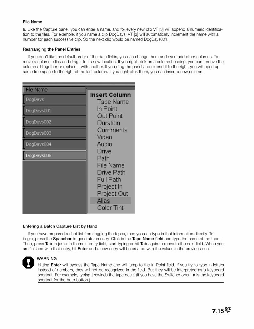
File Name
6. Like the Capture panel, you can enter a name, and for every new clip VT [3] will append a numeric identifica-tion to the files. For example, if you name a clip DogDays, VT [3] will automatically increment the name with anumber for each successive clip. So the next clip would be named DogDays001.
Rearranging the Panel Entries
If you don’t like the default order of the data fields, you can change them and even add other columns. Tomove a column, click and drag it to its new location. If you right-click on a column heading, you can remove thecolumn all together or replace it with another. If you drag the panel and extend it to the right, you will open upsome free space to the right of the last column. If you right-click there, you can insert a new column.
Entering a Batch Capture List by Hand
If you have prepared a shot list from logging the tapes, then you can type in that information directly. Tobegin, press the Spacebar to generate an entry. Click in the Tape Name field and type the name of the tape.Then, press Tab to jump to the next entry field, start typing or hit Tab again to move to the next field. When youare finished with that entry, hit Enter and a new entry will be created with the values in the previous one.
WARNING
Hitting Enter will bypass the Tape Name and will jump to the In Point field. If you try to type in lettersinstead of numbers, they will not be recognized in the field. But they will be interpreted as a keyboardshortcut. For example, typing j rewinds the tape deck. (If you have the Switcher open, a is the keyboardshortcut for the Auto button.)
7.15

Performing a Batch Capture
7. After you have set your In and Out Points, named your tapes and your clips, you are ready to start the ses-sion.
Rehearse Capture
If you want to review your list, hit Rehearse Capture. VT [3] will run through the Batch Capture session; it justwon’t actually capture the clips. If you are adjusting Proc Amp settings or Audio levels, rehearsing the capturegives you a chance to make all your notes.
Capture Selected & Capture All
If you only want to capture some of the clips in the list, Ctrl + click to select them and hit Capture Select.To record all of them, they don’t need to be selected, just click Capture All.
Two panels pop up. In the Insert Tape… panel, check to see if the right deck is listed in Source Preset.
Clip Padding
8. Then, on the left, you can set the Clip Padding, which is the length of time (in seconds) that VT [3] willextend your In and Out Points. For example, if you set an In Point at 00:02:03:00 and you tell VT [3] to pad it byone second, then the capture will begin at 00:02:02:00, a second earlier. Padding occurs on both ends of theclip. In this case, the capture would end a second after the Out Point.
Clip padding affords a little slop factor when you are setting In and Outs, and gives you a little wiggle roomwhen you are editing.
Start Capture
9. Hit Start Capture to begin the Batch Capture. The Insert Tape panel disappears, leaving the Batch CaptureProgress display. VT [3] begins searching for the spot on the tape. When it finds it, it starts capturing.
7.16

When it finishes the first clip, it searches for the second, and so on, until it finishes the list or it prompts youto change tapes. At the end of your session, the clips will be on your hard drives. If you select one in a Filebinand look at its Edit Properties, you will see that it has the Tape Name listed, which along with its timecode, isthe information needed to reproduce the capture.
Saving a Batch Capture Project
10. To save the session, click on File and Save. A File Requester will open to the default, My Projects Folder.Depending on how you organize your material, you may wish to save the project in a more meaningful location.If so, browse to it and give your project a name.
7.17

Notes:
7.18

VT-Edit is the non-linear editing package of VT [3]. On the surface, the interface is clear cut, but as you diginto its multiple layers, the depth of the tools and functions are revealed.
NOTE
For almost every basic editing task, VT-Edit provides numerous ways and places to perform them. Forexample, you can adjust the In and Out Points of a clip in at least ten different ways in VT-Edit. As youbecome familiar with the program, you will settle into your own techniques and workflow. VT-Edit is flex-ible enough to support divergent editing styles.
This is the longest chapter in the manual because VT-Edit is the most feature rich module in VT [3]. But asyou will see in the next couple of pages, you can be editing five minutes after you open it.
Since VT-Edit is such a layered program, there is no linear path to describe it. So, let’s start exploring the sur-face and mine down as we go.
Basic VT-Edit Setup1. From the Main Menu in the Production Desk section, open VT-Edit. Like other panels in VT [3], it will openin the same configuration that it was in when it was last closed.
NOTE
If the Switcher is already open, VT [3] assumes that you are switching live, even if you aren’t. In this case,any new module that you open, including VT-Edit, will be put onto the Switcher’s Preview bus becauseProgram Out is sacred. If the Switcher isn’t open, then any new module always will open onto the Mainbus. You can check where VT-Edit is routed by looking at the panel tag in the upper right corner that saysVT-Ed. If it has a little red dot on it, that indicates that it’s on Main In. If there is no red dot, then right-clickon the tag, and from the Context Menu choose Put onto Main In.
8.1
Chapter 8: VT-Edit

VT-Edit provides a split-screen interface that you can configure in a variety of combinations according to yourworkflow and aesthetics. Also, if you have a two monitor setup, (which is highly recommended when you areworking in VT-Edit), you’ll have much more room to spread out.
2. You will need to see what you are editing. VT [3] provides VT-Vision, a digital monitor that you can load fromthe Main Menu. If you use it, make sure that it is set to Main or PGM. (See Chapter 4 for more info.)
HINT
You can save some valuable desktop space if you hook up an external monitor instead of using VT-Vision.It also serves as a reference for judging what your program looks like in the world of TV.
3. At the top of each pane of the split-screen, you’ll see five tabs labeled Storyboard, Timeline, Spreadsheet,Control Tree, and Filebin. These are the core tools of VT-Edit, which will be discussed in the following pages.When you click on a tab, it opens that tool in one pane of the split-screen.
To begin, click on Storyboard to open it inthe top pane of the VT-Edit panel.
4. Now go to the bottom pane and chooseFilebin.
Adjusting the VT-Edit Panel
You can roll your mouse over any edge of the panel, and click and drag to expand or contract it. To maxi-mize one of the panes, double-click on the tab. To return to the split-screen, double-click on the tab again. Youalso can drag the divider between the panes to maximize a pane, or to increase its relative size. When yourollover the divider bar, the cursor changes to a double-sided arrow with a horizontal break.
There are other tweaks to specific panels that will be described in the context of those panels. As you useVT-Edit, you will find a desktop design that fits your way of working.
8.2

NOTE
Included on the VT [3] Manual Content CD, a tutorial written by Paul Lara explains how you can split theVT-Edit screen to separate the panels vertically instead of horizontally – ideal for people with a dual mon-itor setup.
STORYBOARD
Adding Clips to the StoryboardLet’s get right to it. You have shot your show, logged your tapes, and captured your clips; you’re ready to
edit. As you will find out, often, there is more than one way to accomplish a task in VT-Edit. For example, VT-Edit provides two different, but complementary, ways of editing a program: the Storyboard and the Timeline.Luckily, the two are intimately linked in VT-Edit. Changes in one are immediately reflected in the other, allowingyou to jump between them.
Many editors find the Storyboard a good place to begin an edit session because the interface facilitatesorganizing your clips. They often switch over to the Timeline to add layers and fine-tune the program.
1. In the Filebin, open your clips directory. (The Filebin is very similar to the stand-alone Filebin, which has itsown chapter, so go to Chapter 5 for Filebing details.) If you know the order of the clips in your program, youcan Ctrl-click to select them in that order. Then drag them all at once onto the Storyboard. They will line up,maintaining the sequence in which they were selected.
You always can add clips one at a time. If you want to insert one in between two others on the Storyboard,just drag and drop it between them. Rearranging clips works the same way.
NOTE
If you will be using the Timeline, then before you start dragging clips into the Storyboard, you need tocheck a setting in the Preferences panel which can be accessed from the Main Menu. In Preferences,down the list under EDITING: VT-Edit, is an option called VT-Edit Storyboard A/B track editing.
When you drag a clip into the Storyboard, it is also dropped onto the Timeline. If you choose Single track-row editing, the clips are lined up, one butted next to the other, on a single row of the track. A/B track-rowwill put the first clip on the top track, the next will be placed on the track below, and the third back up to thetop. For now, leave it at the default of A/B.
8.3
A/B track

HINT
To help you visually identify your clips in the Filebin, make sure that your Filebin View Mode (the windowjust below the Control Tree tab) is set to Large Icon.
(If you have added a lot ofcomments to your files, then youprobably should be in Detailsmode.) At the bottom of the LargeIcon is the name of the clip. Youcan change that display by click-ing to select one of the otherFilebin tabs, such as File Type orModified. (This also works in theStoryboard panel.)
Also, if you double-click on the clip in the Filebin, you start QuickPlay, which plays the clip (with audio) onyour VT-Vision or external monitor.
Compatible Formats
In VT-Edit, you can work with a wide variety of video formats including AVI, RTV, and Windows Media files, allin the same project. (For a complete list of compatible formats, see page 3.24.) Simply drag and drop any ofthese files into the Storyboard or Timeline.
2. If you haven’t captured any clips and wish to follow the examples in this chapter, you can load clips andimages from the VT [3] Manual Content CD. To start, in the Filebin, find HorseHerd.avi and MareFoal.avi, anddrag them onto the Storyboard.
Each clip on the Storyboard is represented by an icon, called a crouton. The croutons for each clip aremarked differently.
• Video only files have a blue bar at the top of the crouton.• Audio only files have a green bar.• Video/audio files have a two-tone bar of blue and green. (The green bar becomes yellow if you use a split edit.) They also display a little music note.• Still images have no bar at the top.• DVE (Digital Video Effect) croutons are a bit smaller and also have a bluebar.
Enlarging the Croutons
If you are reaching for a magnifying glass to see the croutons on your 1280 x 1024 monitor, VT [3] has onebuilt into the interface. On the bottom right corner of the Storyboard pane is an icon of a magnifying glass.When you have croutons loaded:
• Click and drag up makes the icons smaller.• Click and drag down makes the icons larger.
8.4
SingleTrack

NOTE
You also can change the look of the crouton to mimic the look of files in the DDR. On the upper right cor-ner of the Storyboard pane is a little down arrow. Click on it. In the Context Menu, choose Small Icon.
Loading Sequences of Images
You can drag and drop a whole folder onto the Storyboard or Timeline.VT-Edit automatically creates a project of all of the files in alphabeticalorder. If they are single frames from an animation, before you drag theminto VT-Edit, you need to open the Preferences panel and change theDefault Still Length (under EDITING – General) to one frame.
The folder will load onto the Storyboard as one crouton. To open it upto see individual frames, right-click on the icon and select Expand Sub-Project. Or you can just double-click on the sub-project icon to play it.(For more information on Sub-Projects, see the end of the chapter.)
Editing Clips on the Storyboard3. You can do some rough editing right on the Storyboard crouton without opening another panel. But it is
interesting and informative to view the Timeline in the lower pane as you work in the upper on the Storyboard.
Click to select the HorseHerd.avi crouton. Move your mouse to the top left corner of the crouton and holddown the Alt key. The cursor will change to say In and the timecode of the In Point of the clip will pop up.
NOTE
When you bring a clip in to VT-Edit, by default the software will automatically set the In Point one secondafter the beginning of the clip, and will put the Out Point one second before the end. This gives room foradding transitions. Of course, you can always move the Ins and Outs because the whole clip is available.But if you want the original In Point to be the beginning of the clip and the Out to be the end, you canchange the setting in the Preferences panel. Under Editing: VT-Edit > VT-Edit Automatic In/Out Offsets,make it No Offset. If you wish to modify just one clip in this fashion, highlight the clip and hit the g key.
8.5
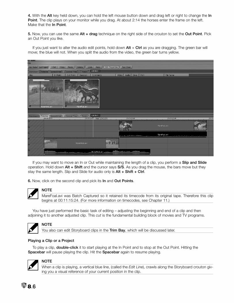
4. With the Alt key held down, you can hold the left mouse button down and drag left or right to change the InPoint. The clip plays on your monitor while you drag. At about 2:14 the horses enter the frame on the left.Make that the In Point.
5. Now, you can use the same Alt + drag technique on the right side of the crouton to set the Out Point. Pickan Out Point you like.
If you just want to alter the audio edit points, hold down Alt + Ctrl as you are dragging. The green bar willmove; the blue will not. When you split the audio from the video, the green bar turns yellow.
If you may want to move an In or Out while maintaining the length of a clip, you perform a Slip and Slideoperation. Hold down Alt + Shift and the cursor says S/S. As you drag the mouse, the bars move but theystay the same length. Slip and Slide for audio only is Alt + Shift + Ctrl.
6. Now, click on the second clip and pick its In and Out Points.
NOTE
MareFoal.avi was Batch Captured so it retained its timecode from its original tape. Therefore this clipbegins at 00:11:15:24. (For more information on timecodes, see Chapter 11.)
You have just performed the basic task of editing – adjusting the beginning and end of a clip and thenadjoining it to another adjusted clip. This cut is the fundamental building block of movies and TV programs.
NOTE
You also can edit Storyboard clips in the Trim Bay, which will be discussed later.
Playing a Clip or a Project
To play a clip, double-click it to start playing at the In Point and to stop at the Out Point. Hitting theSpacebar will pause playing the clip. Hit the Spacebar again to resume playing.
NOTE
When a clip is playing, a vertical blue line, (called the Edit Line), crawls along the Storyboard crouton giv-ing you a visual reference of your current position in the clip.
8.6

If you hit the right arrow key on the keyboard, itwill pause the clip. Click the arrow again and itadvances one frame. Hold the arrow down and itplays the clip. Hold Shift + arrow and the clip willadvance five frames at a time. The left arrow keyplays in reverse.
For a quick review of a clip, Shift + Spacebar willtake you back three seconds and start playing.
You can play the whole project in a number ofways. On the keyboard, hit Home to jump to thebeginning of the project, and then press theSpacebar. Since you didn’t double-click a clip first,the Spacebar command will play all the clips in theproject.
The keyboard shortcut, k, also will play the project. In fact, there is an extensive list of keyboard shortcuts forthe VT-Edit panel – five pages of them. So rather than enumerate them all here, you can access the list whenyou are in the VT-Edit panel by pressing F1 (that’s the Function 1 key at the top of your keyboard).
Deck Controls
The Deck Controls at the base of the panel let you play, pause, stop, and shuttle through your project.
Play, Pause, & Stop
The Play button begins playback of the selection or the project from your current position. The Pause buttonwill hold playback at the current frame. You can hit Play to continue playing, or hit Stop. Double-click on the Stopbutton to jump to the beginning of the selected clip, or to the beginning of the project (if nothing is selected).
Rewind and Fast Forward
The Rewind and Fast Forward buttons let you scan quickly through your project. Double-click on Rewind toscan to the beginning of the project, and double-click on Fast Forward to scan to the end of the project.
Record (Rec)
The Record button brings up the Capture panel. When you capture a project or clip, VT-Edit inserts a newcrouton in the Storyboard and Timeline. In the Storyboard, the new crouton is inserted at the end of the currentselection, or at the end of the project if there is no selection. In the Timeline, the new clip is inserted at the cur-rent marker.
NOTE
When a clip is inserted into the Timeline, the marker is advanced to the end of the clip. When used inconjunction with the Chop command in the Capture panel, you can bring clips quickly into the Timeline.(For more information on the Capture panel, see Chapter 7.)
Jog & Shuttle
The Jog & Shuttle wheel beside the deck controls gives you various speeds to scan through your project,which works with video and audio, so you will hear audio if it exists.
8.7

To use the wheel, you pick Jog or Shuttle and click and drag it left or right. The LEDs under the wheel indi-cate how far you have twisted it. Also, under the timecode display, there is a little speed gauge. (1.0x = regularspeed, -.5x = half speed in reverse, etc.)
If you click Jog and twist the wheel, you can scan through your clips frame by frame. If you click Shuttle, thewheel becomes a variable speed fast forward and reverse.
The LEDs also serve as speed options for playback. You can click on any of them to play the clip. (It doesn’tmatter if Jog or Shuttle is chosen.) Each LED represents an incremental change in speed. The first three LEDsfrom the center play back in slow motion (.3, .5, and .8 of regular speed). The fourth one plays at regularspeed. The LED at the end plays back at double speed. Click the LEDs on the right side to play forward; clickthe LEDs on the left to play in reverse.
Background Render Status
If you look above the Play button, there is a green line, which indicates that the Project is ready toplay. If the line is not on, then VT [3] is busy either background rendering, or perhaps generating
audio waveform displays. However, you still can work on your project: editing clips, setting up effects, etc. Bydesign, background rendering in VT [3] should not disturb your workflow. When the system is ready to play, theline will turn green again. At any time, even if background rendering is not complete, you can play your project,and VT-Edit will continue to operate at whatever capacity your computer allows.
A yellow line warns that the project may not play back smoothly. A yellow line also can indicate that theremay be files missing from your project. These clips will be bordered in red.
Track Clip
With Track Clip checkmarked, you advance to the beginning of the clip automatically when you select thatclip. Also, when you pick a clip in the Storyboard, the Timeline jumps to that clip in its layout.
NOTE
You can change the Track Clip option in the Preferences menu under EDITING: VT-Edit. The choices arejump to the Clip Start, Clip Centre, or Clip End of the clip. The default is Centre.
Looping
You can make the playback Loop, which tells VT-Edit to play the project or selection continuously until youclick the Stop button. You activate the Loop option by clicking on the Loop icon beside the timecode display.
Timecode
The timecode display is simply a clock that indicates your location in the project. The smaller display below itgives the total duration of the project.
The top clock will always display project time, unless you checkmark Local Time; then the current clip’stimecode will be displayed. Depending on how you capture a clip, it will either have timecode already attachedor VT [3] will give it timecode. For example, select MareFoal.avi and see the difference if Local Time is active ornot. If Local Time is not checkmarked, the clock will display project time. (See Chapter 11 for a detailed dis-cussion of timecode and its display.)
If Time Remaining is checkmarked, the clock displays remaining time, (not elapsed time), and counts back-ward. If Local Time also is on, then the clock counts back from the clip’s timecode. When a new clip is played,the display jumps to its timecode. If Local Time is off, then the clock counts back from the project’s timecode.
8.8

TIMELINE MODEMany editors spend most of their time in the Timeline mode of VT-Edit because it provides a clear visualiza-
tion of layers in a project.
Timeline Interface7. If you have been following along, in the bottom pane, click on the Timeline tab, which will replace the Filebin.
While you’re here, click into the Storyboard pane, and notice that its background becomes lighter becauseit is active. Click in the Timeline pane and the Storyboard pane darkens.
If you select a crouton in the Storyboard, you do not select its corresponding clip on the Timeline and viceversa. However, any changes you make to your project simultaneously update both views. For example, if youchange the In and Out points of a crouton in the Storyboard, the clip is updated in the Timeline. When youmove into the Timeline to edit that crouton, you must manually select it, or you can double-click in the back-ground of the Timeline to jump to the same crouton that is selected in the Storyboard.
8. Now double-click on the Timeline tab to expand it. The split screen goes away and the Timeline occupiesthe whole panel.
Take a look around the Timeline. If you are an editor, you will be spending a lot of time here. So becomefamiliar with the neighborhood.
The Timeline interface is composed of three elements: the Edit Line (the vertical blue line), the Time Bar (thehorizontal strip at the top with timecode) and the Tracks that hold your clips.
8.9

Edit LineThe Edit Line is an essential tool. When you roll your mouse over the Edit Line,
(anywhere in the Timeline pane), the cursor changes to bi-directional arrows. Thisindicates that you can click and drag it left or right, moving you back and forththrough your project. You can watch your progress either in VT-Vision or an exter-nal TV monitor. This process is called scrubbing.
On the Time Bar, the Edit Line also displays the timecode in white at its currentposition. You can move the Edit Line without dragging, by clicking on the TimeBar. The Edit Line will jump to that spot. Also, if you double-click on the Edit Line,a little entry field will pop up showing the current timecode. Enter a timecode andthe Edit Line will jump to that location, which can be handy if you are working onan hour-long program. (You also can press Ctrl + g, to bring up the entry field.)
TracksThe Tracks are references for laying out your clips. They are numbered from top to bottom starting at 1a and
1b. The video portion of a clip takes up two tracks and the audio takes one. Audio and video intermingle on theinterface. There are no assigned locations for audio and video. You can freely move clips up and down tracks.Tracks are limited only by your system resources; you can load an unlimited number of layers into the Timeline.
Tracks become significant when you are layering clips. VT-Edit sees clips from the bottom of the timeline up.So if you want to overlay one clip on top of another, the top clip should be placed on a track below the back-ground clip. (Overlays will be discussed later in the chapter.)
Now, double-click on the Time Bar to expand theview to fit the project. On the left side of the inter-face, (to the left of the 00:00:00:00 point on theTime Bar), the tracks have diagonal lines. Again,these markings are for reference, showing you where00:00:00:00 is. Traditionally, editors will begin theirprogram at 00:00:00:00, but they will place colorbars, slate and countdown in this area. Of course, ifyou are a rebel or are feeling gothic, you can layoutyour whole project in that negative time zone area
Zooming and Scrolling the Time Bar and Tracks
The Time Bar depicts major and minor time increments with timecode and tick marks. You can scroll throughthe Time Bar with the scroll bar at the bottom of the pane. Just click and drag it left and right. To zoom in onthe Time Bar and your clips, roll your mouse to either end of the scroll bar. When the cursor says zoom, clickand drag your mouse away from the bar to zoom out horizontally, and toward the bar to zoom in horizontally.
If you hold the Shift key when you zoom, it constrains the other end of the zoom. As you will see in all of thepanels, if you press Ctrl, your dragging will be 10 times more precise. This works on all sliders and twist-knobs.
Now, if you move back up to the Time Bar, with a single mouse click you can move and zoom horizontallyalong the Time Bar. Right-click on Time Bar and if you drag left or right, you pan; and if you drag up or down,you zoom in or out.
To change the height of the tracks, click the magnifying glass at the bottom of the vertical scroll bar on theright. Pull up to enlarge the tracks and down to shrink them.
HINT
To quickly see the entire project in the Timeline pane, double-click in an empty area of the Timeline. (Thisworks if no clips are highlighted in either the Storyboard or the Timeline.) If a clip or clips are selected,hold down the Ctrl key while double-clicking in the Timeline and you will zoom into the selection.
8.10

Customizing Clips on the Timeline
You can change the look of your clips, transitions, overlays and effects by clicking on the down arrow on thetop of the vertical scroll bar on the right, and selecting a new look from the Context Menu that pops up.
Editing Clips on the TimelineRipple Mode
Before you start editing In and Out Points on the Timeline, we need to discuss the concept of Rippling,which is a description of how clips interact in a project. The notion of non-linear editing is that you can put threeclips - one right after another – on the Timeline, adjust the middle clip (for example, make it shorter), and thelast clip will slide (ripple) with it on the Timeline. If you deleted the middle clip, the last one would ripple to takeits place. (If you have a lot of clips on the Timeline and you adjust the In or Out Point of one of clips in thebeginning, then visually – as all trailing clips move – they look like a ripple.)
Though slightly different in their ripple rules, VT-Edit provides a Storyboard Ripple and a Timeline Ripple. InTimeline Ripple, all clips beyond the selected clip ripple by the adjusted amount when you change the In or Outpoint of the selected clip. So, if you decrease the length of the clip by two seconds, all the clips after it on theTimeline will move two seconds down. Ripple doesn’t affect the duration of the other clips, just where theyoccur on the Timeline.
Storyboard Ripple works as though you removed the clip, made your adjustments, and then inserted the clipagain using the rules of Storyboard operations.
Ripple Mode is set to Auto by default, which means it uses Storyboard Ripple when you work on theStoryboard, and Timeline Ripple when you work on the Timeline. You can turn Ripple off in the Timeline modeby right-clicking on an empty portion of the pane and selecting Ripple, Disable. Or you can click on the downarrow on the top of the scroll bar on the right and choose Disable Rippling.
The keyboard shortcut, t, will toggle Rippling on and Shift + t turns it off in the Timeline. You can’t disableStoryboard Rippling from the Storyboard panel.
Locked Audio and Video
If a clip has audio and video, when you add it to the Timeline, separate icons are created for the videostream and the audio stream. By default, those streams are locked – meaning if you change the In or OutPoints of the video, the audio will follow along. If the streams are unlocked, then altering the video stream doesnot change the audio. You can lock or unlock streams, by right-clicking a clip and choosing the option.
NOTE
Locked or Unlocked, if you change the audio stream, the video will not follow. The idea in VT-Edit is that“Video always has priority.”
Adjusting In and Out Points
The In and Out Points are the frames where your clip begins and ends when you play it.
9. If you have been following along since the beginning of the chapter, you have two clips on the Timeline. Fornow, make sure that Ripple is Enabled in the Timeline. Let’s start by adjusting the Out Point of the first clip soyou can see how Ripple works.
8.11

To adjust the clip’s Out Point, roll your mouse over the right edge ofthe video stream. The cursor will say Out. Click and move the edge tothe right to extend the Out Point, or to the left, to contract it. You cansee and hear as you scrub. (This is one of the advantages of settingyour Preferences to A/B track-row editing: you have direct access toyour In and Out Points.) Notice when you move the Out Point, the sec-ond clip follows along – it ripples.
Also, adjusting either the In or Out Point moves the end of the clip.Where the clip starts on the Timeline does not change.
NOTE
When you add a clip to VT-Edit, you import the whole clip, and it is available to you at all times. Thatmeans, if the clip is fifteen seconds long and you set an In Point at five seconds, you haven’t cut thosefive seconds off the clip. If you want to come back later and change the In Point to two seconds, you justgrab the edge and pull it out.
HINT
If your mouse just doesn’t give you the accuracy you need, hold down the Ctrl key at any time when youare dragging, which will give you 10 x the accuracy. In this case, 10 x is plenty to give you single framecontrol.
Or you can try this. Use the method above to set an Out Point later in the clip than you want. Then use theleft arrow key to advance the Edit Line to the exact spot and hit o on the keyboard. (That’s o for Out Point and ifor In Point.) The Out Point is set at the Edit Line. (For this to work, you have to have that portion of the clip onthe Timeline.)
If you’re extremely nimble, you can adjust In and Out Points on the fly. Just click to select your clip, hit play,and hit i and o, as the clip is playing. You can only do this with one clip at a time.
HINT
As in the Storyboard, if you hold the Alt key down when you roll over a clip, the In Point (if you are near-er to it) or the Out Point’s timecode will be displayed.
Slip and Slide
When you move an In or Out, you either lengthen or shorten the clip. If you want to move an In or Out whilemaintaining the length of a clip, you perform a Slip and Slide operation. For example, you originally had a fif-teen second clip and you set the In Point at five seconds and the out at ten seconds, giving you a five secondtrimmed clip.
Now, if you want to start the clip at three seconds, (but keep thefive second length), then you hit Shift + Alt when you drag the leftedge of the clip. You will see your cursor changes to S/S.
8.12

Extending Beyond the Clip’s Beginning or End
You can set an Out Point past the end of a clip. Forexample, the MareFoal clip is about 17 seconds long. Ifyou drag the Out Point of this clip so that the clip’s dura-tion on the Timeline is 20 seconds, you will see a littlered triangular marker, called a bang, at the end of theclip.
The icon indicates that you have overextended theclip. But if you play the clip, you will see that VT [3] sim-ply freezes the last frame in the clip and holds it for theextended length. The same principle applies if youextend the In Point.
Capturing a Still Frame
If you want to edit a clip in the middle and also freeze the Out Point frame for a period of time, then youneed to capture that frame as a still, and butt it up to the last frame. You then can drag the still frame out to anylength of time; and you can apply DVEs to it.
One way to capture a still frame is to scrub the Edit Line to your desired frame. From the Main Menu, openthe Capture panel. Under the Format tab, choose NewTek RTV; and in the Format field, pick 720 x 486Progressive. Under the Options tab, for Input choose Main In, (only checkmark the Video box), check Timedand enter 1 in the Frames field. Under the Record tab, name your image and choose its Path. Click Record,and in a second, you have your still frame, which you can load into your project and stretch to any length.
Picking Progressive instead of Interlaced is the key to stabilizing the image. Interlaced exhibits both fields ofthe frame. By selecting Main In as your input, you record whatever is showing in VT-Edit since it is on Main In. Ifyou have more than one still to capture, you can leave the Capture panel active. Whenever you are ready forthe next still, enter its name and hit Record.
HINT
Using the left and right arrow keys on the keyboard to advance a frame at a time through the clip willhelp you find just the right frame to render.
Moving Clips on the Timeline
To move a clip, simply click it and drag it. As you move, the clip will have a tendency to jerk around becauseit has an almost magnetic attraction to items in the Timeline panel. For example, when the bottom or top of aclip approaches a track line, the clip will jump to that spot, which is called snapping. The clip also snaps to thevertical lines in the panel. Most importantly, a clip will snap to the Edit Line, and the front or end of another clip.The tendency to snap does not stop you from moving the clip wherever you want on the Timeline. (However,clips will insist on sitting on a track line.)
HINT
This is a hint and a warning. If you hold down the Ctrl key before you start dragging, you will make a copyof the selected clip or clips. This is a cool way to quickly copy a clip; unless, of course, you just wantedto move a clip, but you hit the wrong key and you’re leaving copies in your wake.
You can move multiple clips in the Timeline by selecting them, and then dragging them all at once. When youdrag multiple items, only the first item selected snaps. All other items maintain their relative positions to the first item.
HINT
Occasionally, you will want to move a clip up or down in the Timeline, but retain its location on the EditLine. To constrain your movement to vertical dragging only, hold the v key down. It’s important to click onthe v before you click the mouse and drag. And you need to stop dragging and let up on the mousebefore you release the v key.
8.13

NOTE
When you move a clip in the Timeline, the other clips do not ripple to fill in any empty space. They wouldripple if you deleted the clip. But if you move a clip in the Storyboard, the other clips do ripple. That isone of the reasons that you use the Storyboard to organize and rearrange clips.
Transitions & DVEs
VT [3] supplies over 300 DVEs (Digital Video Effects) to you. Though we hope you never use them all – atleast not in one program. In the past, some systems have differentiated between transitions and DVEs.Transitions were simple dissolves or wipes that did not move the actual video picture, while DVEs were digitaleffects that manipulated the video picture. In VT [3], all transitions are digital transitions, and so the terms transi-tions and DVEs are used interchangeably. (Appendix C contains a description of each DVE and the icon associ-ated with it.)
Locating the DVEs
When you install the DVEs, you can choose the directory where you want them placed, or they are installedby default in C:\Content\DVEs. Within that folder are several categorical drawers for different types of DVEs,ranging from Curls to Borders.
NOTE
During the initial auto configuration of VT [3], certain folders were added to your Hotlist. The location ofyour DVE folder was one of them. So the quickest way to access your DVEs is by clicking the Hotlist key.Of course, if you have a favorite group of DVEs that you often use, you could add that folder to yourHotlist. (For more information on customizing your Hotlist, see Chapter 3.)
Inserting a Cross Fade
The most common DVE is the dissolve or Cross Fade. In VT-Edit, you can add a Cross Fade to your pro-gram by simply selecting a clip, (or range of clips), and hitting Alt + f. If you picked one clip, the Cross Fade willautomatically connect the end of the clip with the beginning of the next one, (assuming that the two are touch-ing each other). If you selected a range of clips, Cross Fades will be inserted between each of them. (Thismethod works in both the Storyboard and the Timeline.)
NOTE
If you are observant, you will notice in the first clip’s audiowaveform that the track fades down over the duration of theCross Fade, and the second clip fades up. (You can changethis Auto Fade setting for individual clips in the EditProperties panel discussed later.)
8.14

When you use Alt + f, look closely at the Out Point of the first clip and the In Point of the second. By default,VT-Edit will extend the first clip forward by 15 frames past the original Out Point and the second clip back by 15frames from its In Point. You can change this procedure in the Preferences panel, EDITING: VT-Edit > VT-EditStoryboard Insertion Mode. If you set it to Non-Insertion, then the second clip extends back by 30 framesfrom its original Out Point. The first clip remains unchanged.
HINT
If you are in the mood, you also can drag and drop one clip on top of another. VT-Edit will automaticallyinsert a Cross Fade into the area where the clips overlap.
Inserting a DVE
To add any other DVE, you open the Filebin pane, browse to the directory, and drag the DVE on to theStoryboard or Timeline. If you are in Storyboard mode, you can drop the DVE between the two clips; and VT-Edit will use the Storyboard Insertion mode described above to join the two clips.
NOTE
You set the default length for a DVE in the Preferences menu, EDITING: General > DefaultTransition/DVE Length. If the value is two seconds, then when you drop a DVE into your program, that’sits initial length. You always can adjust it later.
Dropping DVEs in the Timeline is a hands-on procedure. If you are not in Ripple mode, begin by overlappingthe two clips.
8.15

Browse to the DVE folder and drag the DVE onto the ends of the two clips.
HINT
Add Media ButtonAt the top of the VT-Edit panel, the Add Media button launches a File Requester. So if you are totallyimmersed in your Storyboard and Timeline, you don’t need to open the Filebin tab to access files or DVEs.Just click on the Add Media button.
8.16

You can now stretch the DVE out to the desired length.
NOTE
If you are in Ripple mode in the Timeline, then overlapping the clips before you drop the DVE can adverse-ly affect rippling because you have to move your clips to overlap them. If you are in Ripple mode, the eas-iest method would be to drop the DVE into the Storyboard and adjust it in the Timeline.
8.17

Adjusting DVEs
When you roll your mouse over the edge of a DVE, the cursor changes to a slashed frame icon, which indi-cates you are in DVE edit mode. Click and drag the edge of the DVE to lengthen or shorten it. If the DVE isaligned with a clip, the clip’s edge will move with the DVE.
Inheriting DVEs
VT-Edit provides an Inherit feature, which allows you to replace the current DVE with another while maintain-ing the settings of the first. For example, you could insert 3034_Arc.dve and adjust its duration to two seconds,and then you could decide the second clip should fly in from the right instead of the left. Go back to the DVEfolder in the Filebin, hold down the Alt key and drag 3036_Arc.dve right on top of 3034_Arc on the Timeline.(The cursor will say Inherit.)
Release the mouse. The new DVE will inherit duration and location settings of the DVE that was there. Youalso can Inherit one clip for another, which will be discussed later in the chapter.
HINT
A quick way of adding DVEs to the Timeline is to use Alt + f to automatically insert a Cross Fade betweentwo clips. Then just Alt + drag the new DVE over the Cross Fade to Inherit.
Adding DVEs from the Tool Shed
Another way to add DVEs can be found in the Tool Shed. Click on the Tool Shed button on top of the VT-Edit panel. (The Tool Shed will be described in detail later, but this tool can’t wait.) Click on DVEs in the list onthe left, and then Add DVEs.
In the panel, you may not find the DVE that you wantfrom the short pull down list; but you can choose any ofthe 300 DVEs. If the DVE isn’t in the project already, dragit out of its directory and onto the Timeline. Be sure it’sselected, and then click Grab DVE. The DVE’s name andnumber will be displayed above the DVE box.
Now, you can set the duration for the transition. The 1,2, and 3 buttons are just quick ways to enter 1, 2, or 3seconds. Next choose whether the DVE will be addedbetween every clip in the project or only applied to a spe-cific range. Of course, if you pick Time Range, you needto go to the Timeline and mark that range. When youhave, click on Perform and the DVE will be added.
8.18

Trim Bay
The Trim Bay is the panel at the bottom left of the VT-Edit panel where you can perform basic editing opera-tions, like setting In and Out Points. This tool works with both clips and DVEs.
Tour of the Trim Bay
1. Load a clip on to the Timeline. If you have been following along since the beginning, on the Timeline, click toselect HorseHerd.avi. In the Trim Bay, the clip’s information and icon are displayed.
Along the top are four boxes. The first three deal with a clip’s audio and video streams.
Enabling or Disabling Video or Audio Stream
If you checkmark the first box, the one with the little camera icon (which looks a bit like the Little Engine thatCould), then you activate the video stream. By default, this box and the next one are checkmarked. The secondbox, the one with the speaker icon, denotes the audio stream. Occasionally, you will just want to see the videoand not hear the audio, or vice versa. You can control that by marking these boxes.
8.19

NOTE
You cannot disable both video and audio. One or the other has to be enabled. When you disable one,the box on the other grays out, taking away the option. Also the disabled portion of the clip will disap-pear from the Timeline.
Lock or Unlock A/V Streams
In the third box, you can either lock or unlock your audio and video. As described above, the streams arelocked by default, meaning if you change the In or Out Points of the video, the audio will follow along. If thestreams are unlocked, then altering the video stream does not change the audio, and vice versa.
Overlay
If the fourth box is checked, then the clip becomes an Overlay, which will be discussed in detail later. Bydefault, this box is unchecked.
Video Duration
This field displays the length of the trimmed clip in the project. You can type in new times in this box; and theclip will lengthen or shorten by keeping the same In Point, and adjusting the Out Point.
Audio Duration
Works just like Video Duration. If the streams are locked, any change you make in either field will be reflectedin the other. If the streams are unlocked, then the two fields work independently.
2. Type in a new Video Duration for HorseHerd.avi. For example, 10 seconds would be 00:00:10:00.
HINT
Entering Data in Timecode FieldsYou can enter new values in a timecode field (like Video Duration) in two basic ways. Traditionally, youwould click and drag to highlight the numbers that you need to change, and then you would type in thenew data. You also can double click to select the complete timecode. Now, if you type 12 and hit Enter,the new timecode would be 00:00:00:12. If you type 2212, the timecode would be 00:00:22:12. Youdon’t need to type the colons or the leading zeros. So if you want a duration of 1 minute, 22 secondsand 12 frames, you would type 12212 and the display would read 00:01:22:12. Another way is to typea space for any leading 0. For example, 00:01:01:01, could be entered as 1 1 1.
On Disk
This value indicates the length of the clip as it is on the hard drive. As such, the value doesn’t change. Itserves as a guide of how long you can make your Video Duration.
Start
This value indicates where the clip starts in the project. You cannot enter data directly in this field, but it willchange when you move the clip on the Timeline.
Video Trimmer
With this tool you can either use the slider to set In or Out Points, or type in specific timecode. If the streamsare locked, then the changes will be reflected in the Audio Trimmer.
To adjust the In Point, roll your mouse over the ridged left endof the slider, and the cursor will say In. Click and drag the slider.You can see your changes in real-time on your monitor. Also, thetimecode in the window on the left will update in real-time. Theend of the clip on the Timeline will adjust to the new In Point afteryou release the mouse. To set the Out Point, you move the rightend of the slider.
8.20

HINT
Once again, for single frame accuracy in moving the slider, hold down the Ctrl key at any time when youare dragging the slider.
To Slip and Slide, simply grab the slider in the middle and move it left or right. The In and Out Pointschange while the duration of the clip is maintained.
If you are numerically oriented (or perhaps you are working with someone’s timecode log), you can type intimecode for the In and Out Points. Obviously, the timecode displayed in the fields to the left of the slider is theIn Point, to the right is the Out Point.
3. The timecode for HorseHerd.avi was assigned to the clip by VT [3] when it was captured, so it starts at00:00:00:00. Enter an In Point at 2 seconds, 14 frames in, or 00:00:02:14.
In the Timeline, click to select MareFoal.avi. Since it was Batch Captured, it retained its timecode from itsoriginal tape. In the Trim Bay, if you slide the In Point slider all the way to its left, you will see that this clip beginsat 00:11:15:24; and the values in the timecode In and Out fields are based on this timecode.
Audio Trimmer
The Audio Trimmer works exactly like the Video Trimmer. In this panel, if the streams are locked, when youmove the Audio Trimmer, the Video will mirror the change. You need to Unlock the streams for the AudioTrimmer to work independently from the Video Trimmer.
Trimming DVEs
Trimming DVEs is a little different than setting In and Out Points for clips. Usually, you just want to change theduration of the transition. For example, you want to make a Page Curl DVE last for two seconds instead of thedefault of one. To do that, you simply select the DVE; and in the Trim Bay, you enter that value in the VideoDuration field.
If for a special effect, you may want to start a transition in the middle. Then you would adjust the Video sliderbelow Audio Duration. Notice, that for DVEs, the slider has percentages instead of timecode. If you set the slid-er on the left to 30%, then the DVE will start at its 30% spot. If you move the slider on the right to 80%, thenthe DVE will end at its normal 80% spot. Considering DVEs usually make a smooth transition from one clip tothe next, these settings could be a bit abrupt. Try it with the Alien Hand DVE, 7075.
WARNING
An errant mouse can change these percentages from their defaults. If your DVE doesn’t look right, checkto make sure you didn’t botch it here in the heat of the edit.
8.21

Edit Properties PanelAnother powerful module in
the VT-Edit suite is the EditProperties panel. To load it,select your clip or DVE, andclick on the Edit Propertiesbutton in the top row of but-tons on the VT-Edit panel, (oruse the keyboard shortcut, F8).
Touring Edit Properties Panel
This panel contains a widevariety of tools to alter andrefine your clips. Some of themhave already been discussedearlier in this chapter, and oth-ers will be described later. Fornow, the features that areunique to Edit Properties will becovered.
Choosing Ripple Mode
Beginning at the top of thepanel, on the right, a messagetells you the Ripple status ofthis clip. (Ripples are discussedearlier.) As a rule, if the Timelinehas Ripple Enabled, then allthe clips ripple. And if it isDisabled, then none of theclips in the Timeline ripple.
In the Edit Properties panel,you can override that settingon a per clip basis. Right-clickon the Ripple message.
NOTE
Unless you have a specific reason to override the Ripple Mode assigned to a clip by the Storyboard orTimeline, then just leave the mode at Auto.
In the Context Menu, you have four Ripple Mode choices.
• Auto reads the current Ripple status of the clip and main-tains it. For example, if you were in the Storyboard when youselected the clip and opened the Edit Properties panel, thenwhen you click Auto, it will keep the clip in Storyboard Ripple.If you had selected the clip from Timeline view, then it willkeep the clip as Timeline Ripple. If the Timeline had RippleDisabled, then if you select Auto, the clip’s status would stayNo Ripple. When you select Auto, the Context Menu closesand the Ripple message will not say Auto, but will display thespecific mode.
•• Storyboard Locked, when selected, will override the currentRipple Mode of the clip and change it to Storyboard Mode.
8.22

•• Timeline Locked, when selected, will override the current Ripple Mode of the clip and change it toTimeline Mode.
•• No Ripples, when selected, will override the current Ripple Mode of the clip and change it to NoRipples.
S (Skins)
The Edit Properties panel has only one Skin, so the S button is not active on this panel.
Alias Name
If you haven’t previously assigned an Alias to a file, (which you do in the File Properties panel), the name thatpops up in the Alias field is the original file name. If you already had given an Alias to the clip, then it will be dis-played here.
Now – and this is the tricky bit – you can give the clip another Alias that will just apply for this project.Double-click in the field and type in a new moniker. This new Alias name will not replace the original Alias thatwas created in the File Properties panel.
HINT
Why, you may ask, would I want so many different Aliases if my name were not Sydney? Well, let’s sayyou are editing the Garner wedding, you name a clip Kissing the Bride. But what happens when you areediting your wedding demo tape and you have six clips all with the name, Kissing the Bride? You can goin to the Edit Properties panel and give them a project specific Alias, like Garner Kiss, etc.
Pushpin
For those of you who will be using the Edit Properties panel a lot, the Pushpin is a handy displayfeature. Click on it to push it in; and the Edit Properties panel will always stay open and visible,unless you remove the selected clip from the project. Usually, if you clicked outside the panel, itwould disappear; but with the pin pushed in, the panel will be visible and accessible at all times. As
you select different clips, they will be displayed in the panel. Of course, you can still drag the panel to a newposition on the desktop.
Video, Audio & All Tabs
If you have selected a clip with audio and video, then on the top left of the EditProperties panels are three tabs: Video, Audio and All. (If it is an audio only clip,obviously, the Video tab would not appear.) Clicking on the tabs will bring up dif-ferent panels with tools specific to the tab.
Adjusting In and Out Points
The Edit Properties panel is one more place where you can set your In and Out Points. Click on the Videotab to set the Video’s In and Out. (If the streams are locked, it will adjust both audio and video.)
The left window of the panel shows the framefor the In Point; and the right window shows theframe for the Out Point. The blue bar at the top ofthe frame is the video track; the green is the audio.
The middle window shows your Money Shot,which is the frame that serves as the thumbnail inthe crouton. You easily can change the MoneyShot, too.
This wouldn’t be VT-Edit if you couldn’t set theIn and Out points in a variety of ways.
8.23

To Adjust In and Out Points Graphically
1. If you roll your mouse into the In Point window, the cursor turns to a bi-directional arrow. If you click anddrag to the right, you move the In Point to later in the clip. Drag left and move your In Point to an earlier framein the clip.
If you try to drag the In Point beyond the beginning of the clip, the frame in the window may stutter and notlet you move any further. Just release the mouse, then click and drag again; you will be able to set the In Pointwhere you want.
VT-Edit will then hold the first frame of the clip to cover the extended duration. Notice if you do this, bothbars at the top of the frame turn red as a warning.
2. You also can click and hold on the window, and the frames will move at a default speed. If you click and holdon the left portion of the window, the frames will play backward and you will be setting your In Point nearer tothe beginning of the clip. Click and hold on the right; the clip plays forward. When you see your In Point, releasethe mouse.
3. And you also can click repeatedly on the clip to move the In Point one frame at a time. Clicking on the leftpart of the window will move it closer to the beginning, on the right, farther into the clip.
Setting Out Points in the Out Point window on the right works basically in the same way.
NOTE
Hold the Ctrl key to adjust only audio in croutons with audio/video. Even if the streams are Locked, usingthe Ctrl key will move the Audio In and Out independently of the Video. The audio’s waveform also willbe displayed.
8.24

To Adjust In and Out Points with the Mark Button
If you like push-of-a-buttonoperations, then click the PlayClip button that’s above the mid-dle screen. As the clip is playing,click Mark below the In Point win-dow to set the In Point; and clickMark below the Out Point windowto set the Out Point. If you need tofine tune the spots, use the previ-ous method or the one below.
To Adjust In and Out Points Numerically
Next to the Mark buttons are the timecode displays for the In and Out Points. You can click in the one on theleft and enter the exact timecode for the In Point. The one on the right is for the Out Point. (See the Hint abouton Entering Data in Timecode Fields on page 8.20.)
To Adjust the Money Shot
By default the Money Shot will always use the center frame between your In and Out points to representyour icon. When you adjust the Money Shot, you simply change which frame represents the clip. You can pickyour Money Shot frame with the same methods as setting In and Outs.
NOTE
When you change the position of the Money Shot, it will no longer automatically center.
Playing the Clip
To play the clip from the Edit Properties panel, click the Play Clip button on top of the Money Shot window.To loop the clip, click on the curved arrow button to the left of Play Clip. To scrub through the clip, click anddrag the bi-directional arrow next to the loop button.
To Adjust Audio In and Out Points
As was mentioned, you can set the In and Out Points for the audio stream from the Video tab by clicking onCtrl while scrubbing. You can set them in the windows in the Audio tab without having to hold down Ctrl. Tozoom into the waveforms, right-click in the In or Out Point window and drag right; dragging left will zoom out.You also can view and zoom the audio waveforms in the windows in the Video and All tabs.
General Options
Below the In and Out windows, a few generaloptions are available with any stream that youchoose, so they are always visible to you in allthree tab panels.
8.25

Offset
The Offset field lets you enter the amount of time that offsets the clip from the adjacent clip preceding it inthe Project. Often, you leave this setting at zero so that one clip moves straight to the next. When creating anOffset, the Storyboard inserts a black box in the Offset space.
You can type in a time, or click and drag the bi-directional arrow key.
Offset uses the first active stream of an audio/video clip, which is always the video stream, as the reference.You can apply Offset to the audio stream with the Offset controls under the Audio tab. You would do this, forexample, if you had syncing problems between the audio and video. Of course, if you have an independentaudio clip, you can offset that audio clip in relation to the clip before it. The Reset button lets you set Offsetback to zero.
Speed
You can adjust the playback speed of your clip so that it plays faster or slower. Values below 100% will giveyou slow motion, and above 100% will yield faster playback.
When you change the Speed, you also change the Duration of the video. For example, if you enter a slowmotion value of 50%, the Duration will double.
1. In the Timeline, select MareFoal.avi. For this example, trim the clip to about five seconds.
2. In the Edit Properties panel, change the Speed to 25%. Notice the Duration is now 20 seconds. Play theclip. (Echoes of Eadweard Muybridge.)
3. If you click on the down arrow next to Speed, you can adjust speed by using the Scale or FPS (frames persecond) settings. All three have the same effect. Normal speed in Scale is 1, in FPS is 29.97. Slow motion inScale are numbers greater than one. 2 Scale = 50% Speed = 14.99 FPS.
Duration
The Duration field tells you how long your video clip is, and lets you change the out point in real-time. Whenyou drag Duration or type a value with a length beyond the actual length of the clip, the preview window showsa red band as a warning. You hold the last frame of the video when you extend it past its actual length; you donot stretch the entire clip. To stretch the clip, use Speed. Hitting Reset brings the Duration back to the totallength of the clip.
Start
The Clip Start Time tells you the timecode where your selected clipstarts in the overall project. If you move your clip, this time will update.(Compare this start time to the time displayed when you move the Editline to the first frame of your selected clip.)
Lock A/V Streams
Lock A/V Streams is a toggle control that you can use to separate or synchronize the audio and videostreams of an audio/video crouton. By default, the control is ON, so the streams are locked. When the streamsare locked, any changes you make – moving, trimming, deleting, and so on – affect both streams. When youunlock the streams, you can make changes to the streams independently. If the clip is not an A/V clip, this fea-ture is disabled.
8.26

Overlay
You activate the Overlay option when you want to overlay one video on top of another. This feature is dis-cussed later in the chapter. By default, this box is unchecked.
Reverse
The Reverse option lets you run the selected clip in reverse. The feature is set to Off by default.
Control Tree
The Control Tree at the bottom of the Video panel also can be accessed from the main VT-Edit panel.Opening it from there provides a larger interface, so it will be discussed in that context on page 8.29.
Adjusting Audio
Click on the Audio tab to bring up the Audio panel. The top half is very similar to the Video panel. The bot-tom half has two tabs, Basic and Advanced.
Basic
Often you want to handle the left and right tracks onyour clip together. The Basic panel’s Volume control doesjust that by acting as a Master Volume for both channels.The slider is incremented in decibels. Move the slider tothe left to decrease volume; slide to the right to increase it.The default setting, 0 dB, will playback your clip at the vol-ume set when originally captured.
Adjusting audio is a combination of listening closely (soyou can judge which parts of the clip require more or lessvolume), and of monitoring the Audio Mixer’s VU meters (togive you an objective guide to the consistency of volume between clips). Also, the Audio Mixer’s VU meters willguard against overmodulation. (See Chapter 10 for more information on mixing audio.)
Checkmarking Mono will take the clip’s two stereo channels and mix them together into a single source thatis fed out equally through both channels. If you watch the Audio Mixer’s VU meters, you can see the differencebetween turning Mono On or Off.
Activating the Mute box turns off the volume for the whole clip.
You can set different keyframes along the path of the audio track by clicking on the Sine wave icon next tothe Master data entry field, which pops up a Spline interface. (And yes, we’ll discuss this later. But not muchlater, we’re almost there. You always can jump ahead to the Spline Editor section on page 8.60.)
Advanced
The Advanced tab gives you individual volumecontrols over the left and right channels of the Audiotrack, including separate Spline controls.
Left Pan
The defaults of –10 for Left Pan and 10 for RightPan will keep the two channels separate. If for exam-ple, you set Left Pan to 0, then the Left channel’s sig-nal is being sent to both channels. If you set Left Panto 10, then the Left channel is only being sent to theright. The effective range is –10 to 10. If you want toswitch channels, set Left Pan to 10 and Right Pan to–10.
8.27

• Rotate Left Pan clockwise to send more of its signal to the right channel. • Rotate Left Pan counterclockwise to send more of its signal to the left channel.
Right Pan
• Rotate Right Pan clockwise to send more of its signal to the right channel. • Rotate Right Pan counterclockwise to send more of its signal to the left channel.
Balance
The Balance control will mix the channels. The effective range is –10 to 10. Even if Balance is set at –10, youstill will be mixing in some of the right channel. If you don’t want to hear the right channel, then turn its volumeall the way down.
• Rotate Balance clockwise to mix in more of the signal from the right channel. • Rotate Balance counterclockwise to mix in more of the signal from the left channel.
Automatically Fading Audio
To create a simple fade at the beginning or end of an audio track, you can use the Fade In and Fade Outcontrols under Fade & Balance.
By default, the Auto button is activated. When it is, the Fade In & FadeOut fields use the timing from a tran-sition or DVE to fade audio in and out. For example, if you have inserted a one-second Page Curl between twoclips, the audio on the first clip will begin fading out as soon as the DVE starts; and at the end of the transition,it will be totally faded out. The audio from the second clip will fade in from silence to full volume during the one-second transition.
To set your fades manually, you need to turn off the Auto button. (Click it so it isn’t highlighted.) Then use thebi-directional arrow slider to specify the amount of time to fade up from silence, or to fade out to silence. Orsimply type in a time.
HINT
If you don’t want your audio track to fade during a transition, turn off the Auto button and leave the FadeIn and Fade Out boxes at 0.
All Tab
The third tab in the Edit Properties panel is All.The only difference between the top half of the Allpanel and the other two tabs is this: in All, the InPoint and Out Point windows overlay the audiowaveform on top of the video.
In the bottom half of the All panel are anotherthree tabs: Comments, Instant Assets, and FileAssets. VT [3] has an underlying database structureto its file system that you can see and manipulatefrom the Spreadsheet module of VT-Edit (see page8.79). These three tabs are part of that structure.
Comments
The Comments panel lets you read and add notesto your file. Enter notes in the blank field. You canadd and see Comments in the Spreadsheet. Anyinformation that you add here is only accessed withinthe project.
8.28

Instance Assets
To begin, you must click Add and choose a categoryfrom the drop down list. For example, Add a MemoField, name it Ranch, and in the field, type in EarlyMorning. Then in the Spreadsheet, you could sort filesby the Memo Field. Again, the information added here isonly accessed within the project. Of course, you couldname the Memo Field anything like Shot Location orColor Temperature.
File Assets
This panel displays the same file information that youwould see if you opened a file’s Properties panel in theFilebin.
CONTROL TREEThe Control Tree interface packages all of VT-Edit’s creative clip adjustment tools under one tent. To add to
the power of the tools, they all can be customized using spline controls.
Basic Control Tree Setup
1. If you don’t have VT-Edit open, load it from the Main Menu.
2. To keep it simple, load a couple of video clips. If you want to follow along, you can load HorseHerd.avi fromthe VT [3] Manual Content CD.
3. For now, put the Timeline in the top of the VT-Edit split-screen and click on the Control Tree tab to open itin the bottom panel. You’ll need either a VT-Vision or an external monitor. (See the beginning of the chapter fordetails on setting up your VT-Edit desktop.)
4. As always, you will need to select a clip before you can work on it in the Control Tree. Select HorseHerd.avior one that you have. For our purposes, it doesn’t need to be any longer than 30 seconds.
5. After selecting the clip on the Timeline, grab the divider between the two panes and drag the Control Treepane up to expand it. If you leave a little room for the Timeline, you can easily access the clip. (Or you coulddouble-click the Control Tree tab above the open Control Tree pane, which will expand the pane and hide theTimeline pane.)
8.29

Control Tree Interface
Take a look around the interface. On the left are the tools; on the right is the Control Tree Work Area, whichhas two tabs on the bottom left of the window, Splines and Positioning. These panels will be discussed indetail starting on page 8.53; meanwhile, open the Positioning panel because you can use it as a great visualreference for the following discussion on the Control Tree tools. Of course, the Positioning panel is irresistible,but for now, let’s start with the tools at the top of the Control Tree and work our way down.
NOTE
A + icon next to a category means that there are more items nested inside. Click on the + to open thecategory.
Layer Settings 6. Click on the + to expand Layer Settings.
High Quality
When you are positioning and scaling, this setting deter-mines whether the algorithm being used is rendered in high orlow quality. In High Quality, full interpolation and sub pixel cor-rection is performed. High Quality takes about 30% moreCPU usage than low quality.
HINT
To increase the ability of VT-Edit to render a very largenumber of overlays or clips, try not Enabling HighQuality for some of your overlays. This often looks fine,especially when a clip has not had its position animat-ed.
8.30

BG Color
If you scale the dimensions of the clip to lessthan 720 x 486 (NTSC), then you need to decidewhat will show in the Background. By default, theBG Color is transparent (0 Alpha), which is what youwant when you overlay the clip.
If you don’t make the clip an Overlay, then youcan make a semi-transparent or opaque background by clicking in the box next to BG Color, which will bringup a Color Picker. Or you can right-click in the box to activate the Eyedropper tool, and then you can select acolor from anywhere on the desktop. (For more information on the Color Picker, see Chapter 14.)
7. Before you pick a BG Color, jump down to the Size tool, and click on the + next to it to open it. In Size %,enter 70.
NOTE
You could and should have a TV monitor hooked up, but for visual feedback within the Control Tree, clickon the Positioning tab.
8. Now you’ll be able to see your BG Color, so pick one. For example, with the Eyedropper tool, you coulddrag over the icon of the clip and find a color in there.
9. Click on the + next to BG Color to show its components. If you picked a color, then it will be reflected in theRed, Blue, Green, and Alpha Component values.
You can adjust these four items separately by clicking and dragging their knobs to the left for lower values,and to the right for higher ones. The range is 0 to 255. Or you can type in new values. (If Red, Blue, and Greenare all set to 0, then the color will be black. If they are set to 255, the color will be white.)
HINT
This has been mentioned before, but it is worth remembering: Almost always in VT-Edit, when you areusing the mouse to twist knobs or slide sliders, you can achieve ten times the accuracy by holding theCtrl key when you twist or slide or drag.
8.31

What is even more important about these color component items is that you can keyframe them over theduration of the clip. So you could start out with a brown opaque background, turn it to a semi-transparent redin the middle of the clip, and by the end, make it totally transparent.
NOTE
You can tell if an item is keyframeable in two ways. First, if you click on the white box to the left of itsname, the box will turn into a circle with an X in it, which also puts the item’s line in the Spline Editor.Second, you’ll notice that any item with a white box also has a numeric data entry field.
Playback Speed
This tool is its own special animal with its own unique circumstances, which will be discussed in detail in thePlayback Speed step by step later in this chapter. For now, Playback Speed gives you the ability to ramp thespeed. For example, Playback Speed allows you to start a clip at full speed, then gradually slow it down in themiddle, and then ramp it up to full speed at the end. In contrast, the Speed setting in the Edit Properties panelis a constant. If you set the speed at 50%, the whole clip plays at that speed.
WARNING
If you can’t wait for another few pages to experiment with Playback Speed, jump ahead to the step bystep on page 8.66. With this tool, your exploration will be more fruitful with a little guidance.
Alpha
Alpha controls the transparency level of the clip, but not of the background color. The range is from 0 to 255.255 makes the clip totally opaque, 0 turns it completely transparent.
10. To see how Alpha works, change the BG Color to a bright red and then twist Alpha towards 0 and youcan see the red come through. When you’re finished testing, bring Alpha back to the default of 255.
HINT
If you have changed a setting and want to return to the default, then double-click on the knob.
Alpha Advanced
Click on the box to open Alpha Advanced. These tools applya transparent radial gradient to the corners of the clip. Their val-ues are applied on top of the overall Alpha.
11. Open Alpha Advanced and rotate Bottom Right to 0.Notice that it is totally transparent right on the corner andbecomes gradually less transpar-ent in a radial pattern.
12. Now, go up to the Alpha set-ting and make it about 150.Notice that none of the AlphaAdvanced settings changed.
13. Unless you are looking forthis specific effect, reset all theAlpha settings to their defaults.
8.32

3D PositionNow the real fun begins. With the 3D tools, you can fly
your clips around the screen, rotating them every which way.When you click on the 3D Position box, you reveal three tools,which work on the same Cartesian system used in LightWave3D.
X Position
Adjusting the X Position moves the clip to the left or right. Distance is measured in pixels. You can type invalues. Negative numbers will move the clip to the left.
• Click and drag left on the circle in the square icon to move the image left.• Click and drag right on the circle in the square icon to move the image right.
NOTE
If you look closely, you’ll see that the circle in the square icon will display graphically the status of yourmovement.
Y Position
Adjusting the Y Position moves the clip up or down. In this instance, negative numbers move the clip up.
• Click and drag left on the circle in the square icon to move the image up.• Click and drag right on the circle in the square icon to move the image down.
Z Position
Adjusting the Z Position moves the clip back or forwards. Positive numbers move the clip back. Z Position isnot measured in pixels. A setting of 0 is the normal default. If you move Z to 1 the clip will be exactly 50% size.
• Click and drag left on the circle in the square icon to move the image forward (larger).• Click and drag right on the circle in the square icon to move the image backward (smaller).
8.33

14. Move the clip all the way off screen to the left. Since the video frame is 720 x 486 pixels (NTSC), to move afull sized clip all the way off frame on the left, you would need to set X Position to –720. But if you have resizedthe clip to 70%, then you wouldn’t have to move it that far. If you want to be exact, then do the math. Or readthe Hint below.
HINT
When you are positioning your clips, turn your external monitor to Underscan, which will reveal the veryedge of the video signal. If your monitor doesn’t have Underscan, then look at your work on VT-Vision setto Underscan. Often, you’ll be surprised to see that you haven’t quite scooted the image far enough.
15. Reset X and Y. Now slowly slide Z into the negative range. The clip will get bigger, but if you go past about-.9, the clip disappears and you’ll see the background. If you want to enlarge the clip more, use the Size tool.
16. So you can see how the other tools work, bring the 3D Position settings back to their defaults.
3D RotationWhen you are rotating a clip in 3D space in the Control Tree, imagine
three rods going through the clip. The X rod bisects the clip horizontally,the Y bisects vertically, and the Z goes right through the middle from frontto back. So when you adjust the Angles, the clip rotates around thoserods. For example, when you adjust the X Angle, the clip is rotatingaround that horizontal rod.
The rotation is measured in degrees. 360 degrees = one full rotation.
X Angle
• Click and drag left on the circle in the square icon to bring the bottom of the clip forward.• Click and drag right on the circle in the square icon to bring the top of the clip forward.
Y Angle
• Click and drag left on the circle in the square icon to bring the left side of the clip forward. • Click and drag right on the circle in the square icon to bring the right side of the clip forward.
Z Angle
• Click and drag left on the circle in the square icon to bring the left side of the clip down. • Click and drag right on the circle in the square icon to bring the right side of the clip down.
WARNING
These descriptions for Angle rotations are based on rotating one angle when the other two are at theirdefaults. The directions can seem wrong if you are adjusting all three at once, especially if you haveflipped one 180 degrees.
If you want to rotate the clip around a pivot point that is somewhere else than the middle of the clip, you canadjust the X and Y Centre values. (Did we mention that Andrew Cross is from England where they speak withaccents and insist on spelling Center funny.)
Let’s go back to the rods. The point where the X rod intersects the Y rod on the clip has a value of 0 on theX (horizontal) and 0 on the Y (vertical). If you move the X Centre, then the Y rod moves to that point on the clip;and when you adjust Y Angle, the clip now will rotate around that spot. So changing the X Centre affects the YAngle, and changing the Y Centre affects the X Angle.
Distance is measured in pixels and is based on the full-sized clip. So if you want to rotate the Y Angle fromthe left edge of the clip, you set X Centre to –360.
8.34

X Centre
• Click and drag left on the circle in the square icon to move the X Centre left. • Click and drag right on the circle in the square icon to move the X Centre right.
Y Centre
• Click and drag left on the circle in the square icon to move the X Centre up. • Click and drag right on the circle in the square icon to move the X Centre down.
16. Rotate the Y Angle 180 degrees. You have just flipped your image, which can be helpful occasionally.
NOTE
You also can flipan image by spec-ifying a negativevalue in Size (%, X,or Y).
17. Move the clip with the3D Position tools. Now,rotate the X Angle. Noticethat the clip is still rotatingfrom its center. The pivotspot does not change bymoving the clip in 3Dspace. Reset everythingback to 0.
18. Change the Y Centreto 240. Now, slide your XAngle back and forth. Youhave moved the pivotpoint to the bottom of theclip, so it rotates fromthere.
19. Change the X Centreto 360 and play with ZAngle. You have movedyour pivot point to X = 360,Y = 240, which is the bot-tom right edge of the clip.
20. After you have madeyourself dizzy with all thespins and flips. Set every-thing except Size back totheir defaults.
Remember all thesetools can be keyframedover the duration of theclip.
8.35

SizeWhen you load a clip or an image into VT-Edit, by default, it is sized to fit in the video format. For images, the
process involves making the entire image visible on screen without altering it.
21. Load BofP.tif from the VT [3] Manual Content CD, and drag it on to the Timeline. Click to select it, and itwill load into the Control Tree. Now, open the Size tools (if you haven’t already).
As you see, since the height of this image had to fit into the video frame, VT-Edit resized the image by 50%,(972 x 50% = 476, which is the height of NTSC video). The spaces on the left and right show as black, but theyare really transparent. And if Overlay is turned on, the image in the background will show through.
8.36

Size %
This tool reduces or enlarges the image or clip by the percentage that you enter.
• Click and drag left on the circle in the square icon to reduce the size of the image. • Click and drag right on the circle in the square icon to increase the size of the image.
X Size
This tool reduces or enlarges the width of the clip. The values are in pixels. By default the value is the originalwidth of the clip (or image) when it was loaded into VT-Edit. Notice that as you change X Size, the oval in thecircle will reshape to reflect the new values.
• Click and drag left on the circle in the square icon to reduce the width of the image. • Click and drag right on the circle in the square icon to increase the width of the image.
Y Size
This tool reduces or enlarges the height of the clip. The values arein pixels. By default the value is the original height of the clip or imagewhen it was loaded into VT-Edit.
• Click and drag left on the circle in the square icon to reduce the height of the image. • Click and drag right on the circle in the square icon to increase the height of the image.
Src Aspect Ratio
If you want to reshape the image or clip according to a certain ratio, you can use Src (Source) Aspect Ratioand Dst (Destination) Aspect Ratio.
For example, if you change an NTSC 4:3 clipinto a 16:9 format, you would enter 1.78 in theSrc Aspect Ratio field and 1.33 in the DstAspect Ratio. This will stretch the clip and putblack strips at the top and bottom of the frame.
Dst Aspect Ratio
Works in tandem with Src Aspect Ratio, (seeabove).
HINT
Many of the common reformatting oper-ations are included as Spline Presets inthe Tool Shed. (See the Spline Preset dis-cussion starting on page 8.67.)
8.37
Top 4:3, Bottom 16:9

CroppingWhen you crop a clip, you are cutting off portions of the image.
Crop %
This tool takes an equal percentage from each side of the clip, which can be useful if you want to trim offunwanted borders. Negative values have no effect. A 10% crop will take 5% of the clip’s width off the left edgeand 5% off the right. It will take 5% of the height off the top and 5% off the bottom.
Crop Left
This tool trims off the left edge of the clip. The measurement is in pixels and negative values have an effect if the cliphas been cropped already with the Crop % tool. For example, if a 720 x 480 clip has been trimmed 20%, then a CropLeft of –72 pixels will return the left edge to its uncropped state. Any negative value beyond –72 will have no effect.
Crop Right
This tool trims off the right edge ofthe clip.
Crop Top
This tool trims off the top edge ofthe clip.
Crop Bottom
This tool trims off the bottom edgeof the clip.
22. Select HorseHerd again and shaveoff about 3% with the Crop % tool,which will crop off any unwanted blackedges sometimes found in DV footage.
Colored BorderThis tool will make a border around your clip. Think of it as framing a picture. You can pick the width and the
inside and outside colors of the border.
Inside & Outside
These tools work in tandem to define the Border widthcombinations. They can shift positions with certain settings, sodon’t worry if the Inside becomes the outside part of the bor-der. These settings have no connection in determining theInside and Outside Border Colors.
If you want the border to begin at the edge of the clip, thenone of the two needs to be set to 0. Negative values willextend the border outside the edge of the clip. Positive num-bers move the border inside the edge of the clip.
8.38

Inside & Outside ColorYou can pick two colors and a gradient will be made between them that will color the border. The colors are
specific. No matter which way you adjust Inside and Outside width settings, Inside Color will always be theinside color of the border. Of course, if you make the Inside Color and Outside Color the same, you will create asolid border.
Both tools have their drop down Red, Blue, Green and Alpha Components.
23. On HorseHerd, start by making the Inside Color blue and the Outside Color white. You won’t be able tosee the colors until you make the Outside -.10. Leave the Inside at 0.
24. Now, change the Outside to .20. Notice that it becomes the inside of the border, but the Inside Color stillremains blue.
25. Make Inside .10 and notice how the edges of the clip are peaking out past the border.
26. Just to confuse you, set Inside to 0, whichwill put it back to the edge of the clip; andmake Outside to -.30, which brings it back toits original status as the outside of the border.Now, change the Outside Color to the sameblue as the Inside Color, and you get a solidframe. Go back to the Outside Color andchange its Alpha to 0, and you create a gradi-ent from solid blue on the inside of the borderto totally transparent on the outside.
8.39

HINT
If the inside of the border is inside the edge of the clip, the clip edge will be visible through the gradienttransparency.
27. Make the Outside Color a solid white again and bring Outside back to a more reasonable -.15.
Position – Left, Right, Top & Bottom
You can adjust the position of each edge of the border separately. These four tools use the same units ofmeasurement as the Inside and Outside tools.
28. From the example above, if you set Left and Right to .15, you would move those edges in, making almost asquare border.
Width – Left, Right, Top & Bottom
You can adjust the width of each edge of the border separately. These four tools use the same units ofmeasurement as the Inside and Outside tools. Negative numbers expand the width; positive ones contract it.
29. Try this. Set Top Width and Bottom Width to .15. Then go up to Position and in Top, type .075. The dis-play will read .08, but it has accepted the value you typed. Enter .075 for the Bottom Position.
8.40
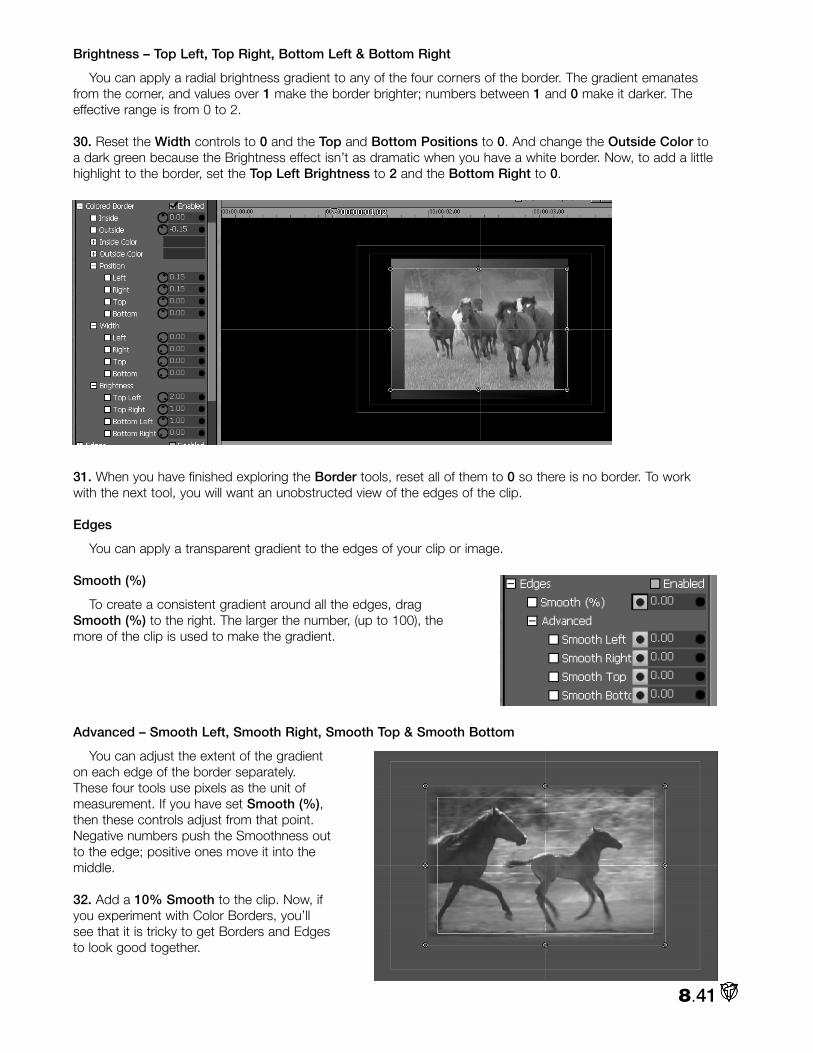
Brightness – Top Left, Top Right, Bottom Left & Bottom Right
You can apply a radial brightness gradient to any of the four corners of the border. The gradient emanatesfrom the corner, and values over 1 make the border brighter; numbers between 1 and 0 make it darker. Theeffective range is from 0 to 2.
30. Reset the Width controls to 0 and the Top and Bottom Positions to 0. And change the Outside Color toa dark green because the Brightness effect isn’t as dramatic when you have a white border. Now, to add a littlehighlight to the border, set the Top Left Brightness to 2 and the Bottom Right to 0.
31. When you have finished exploring the Border tools, reset all of them to 0 so there is no border. To workwith the next tool, you will want an unobstructed view of the edges of the clip.
Edges
You can apply a transparent gradient to the edges of your clip or image.
Smooth (%)
To create a consistent gradient around all the edges, dragSmooth (%) to the right. The larger the number, (up to 100), themore of the clip is used to make the gradient.
Advanced – Smooth Left, Smooth Right, Smooth Top & Smooth Bottom
You can adjust the extent of the gradienton each edge of the border separately.These four tools use pixels as the unit ofmeasurement. If you have set Smooth (%),then these controls adjust from that point.Negative numbers push the Smoothness outto the edge; positive ones move it into themiddle.
32. Add a 10% Smooth to the clip. Now, ifyou experiment with Color Borders, you’llsee that it is tricky to get Borders and Edgesto look good together.
8.41

ShadowsIn the Control Tree, a Shadow is basically a background that is locked to the clip. A Shadow will inherit the
clip’s Size, Position, Rotation, Cropping and Edges; but you can make the Shadow any color or transparencyyou wish.
NOTE
If Shadows are enabled, then Borders also will cast a shadow, but you cannot control its softness withthe Shadows tools. The only way to soften the outside shadow edge of a Border is to make the Border’sOutside Color transparent.
X Offset
Usually you offset the shadow to one corner of the clipor image.
• Rotate the knob left to move the shadow to the leftof the clip. (Moving left produces negative numbers.) • Rotate the knob right to move the shadow to theright of the clip.
Y Offset
• Rotate the knob left to move the shadow abovethe clip, (resulting in negative numbers). • Rotate the knob right to move the shadow belowthe clip.
Edge Smoothness (%)
Even though a shadow reflectsthe clip’s Smooth settings, you canadjust the shadow’s Edge separate-ly. Dragging to the right willincrease Smoothness.
If the clip has Smooth Edges andyou want to give the shadow hardedges, then set its EdgeSmoothness to the negative valueof the clip’s Smooth (%). For exam-ple, if the clip’s Smooth (%) is 10,then the shadow’s EdgeSmoothness would be –10 to giveit a hard edge.
Color
If you open up the Color control, (click on the + box next to Color), you’ll see that the default shadow coloris black with an Alpha of 100, which is semi-transparent.
You can pick another color by clicking in the box next to Color, which will bring up a Color Picker. Or you canright-click in the box to activate the Eyedropper tool, and then you can select a color from anywhere on thedesktop. Or you can adjust the Red, Blue, Green, and Alpha Components.
8.42

33. Adjust the shadow’s X and Y Offsets to 30. Now, create a Color Border and notice how it also casts ashadow, (which is distinct from the clip’s shadow).
(These 33 steps have taken us a long way, but no farther. You can stop counting – this was the last one.)
Color CorrectionThe Control Tree provides three different sets of tools to color correct your clips or images. They all interact,
so a change in one will be reflected in the values of the other two. You can achieve similar results with any ofthem, so use your favorite system.
If your program will be seen on a TV, then you need a good external TV monitor when you are color correctingclips. VT-Vision should be used to check on illegal colors, (see Chapter 4); but a computer display is not a reliableindicator of how images will appear on TV. Also, you should check levels with VT-Scope, (see Chapter 16).
8.43

NOTE
When you are experimenting with the different Color Correction tools, test them on the ntsc_color-bars_75.rtv that is in the Effects\Patterns folder.
Color Correction (Basic)
Brightness
The Brightness control adjusts the luminance (lightness and darkness) of the video signal.
• Rotate the knob clockwise to increase Brightness, and lighten the image.• Rotate counterclockwise to decrease Brightness, and darken the image.
Contrast
The Contrast control adjusts the levels of gray in the signal, which affect the brightness and saturation of animage.
• Rotate the knob clockwise to increase Contrast; the image appears brighter and more saturated.• Rotate counterclockwise to decrease Contrast; the image appears darker and less saturated.
An image with extreme areas of darkness and lightness might benefit from reduced Contrast. If your footagelooks washed out, try increasing Contrast.
8.44

Saturation
Saturation is the intensity of color in the video signal. Low saturated pictures look gray; and overly saturatedimages show colors that bloom to the point of smearing.
• Rotate clockwise to increase Saturation.• Rotate counterclockwise to decrease Saturation.
A video where colors seem too intense, especially where some colors bleed into others, would benefit fromdecreased Saturation. Red colors are particularly susceptible to bleeding in composite and Y/C signals.
The default Saturation value is 1. A value of 0 will remove all color resulting in black and white video.Negative Saturation values open up a whole new world of colors.
Hue
The Hue control adjusts the relativephase of color and works on the prin-ciple of a color wheel. As you rotatethe knob either way, you cycle throughthe colors. The functional range isbetween 0 and 360.
Color Correction – RGB
Red Gain
Red Gain is similar to Saturation, except that when you adjustthe Red Gain, you increase or decrease the saturation of only thered portion of the video signal. If you look on VT-Scope’s vec-torscope, you will see that Red Gain affects Red, Magenta andYellow.
• Rotate clockwise to increase red saturation.• Rotate counterclockwise to decrease red saturation.
Though you can twist the knobs further, if you look on VT-Scope’s waveform monitor, you’ll see that theeffective range is 0 to 1.5. Adjusting Red Gain to 0 will take all the red out of your clip or image.
Green Gain
Green Gain is similar to Saturation, except when you adjust the Green Gain, you increase or decrease thesaturation of only the green portion of the video signal. Green Gain affects Green, Yellow and Cyan.
• Rotate clockwise to increase green saturation.• Rotate counterclockwise to decrease green saturation.
The effective range is 0 to 1.5. Adjusting Green Gain to 0 will take all the green out of your clip or image.
Blue Gain
Blue Gain is similar to Saturation, except when you adjust the Blue Gain, you increase or decrease the satu-
8.45

ration of only the blue portion of the video signal. Blue Gain affects Blue, Magenta and Cyan.
• Rotate clockwise to increase blue saturation.• Rotate counterclockwise to decrease blue saturation.
The effective range is 0 to 1.5. Adjusting Blue Gain to 0 will take all the blue out of your clip or image.
NOTE
If you set Red, Blue and Green Gain to 0, you will create a totally black image.
Red Offset
Red Offset is similar to Red Gain, except when you adjust the Red Offset, you are affecting every color in thevideo signal, even black.
• Rotate clockwise to increase red saturation.• Rotate counterclockwise to decrease red saturation.
Adjusting Red Offset will shift the signal diagonally in the vectorscope. The range is –255 to 255.
Green Offset
Green Offset is similar to Green Gain, except when you adjust the Green Offset, you are affecting every colorin the video signal, even black.
• Rotate clockwise to increase green saturation.• Rotate counterclockwise to decrease green saturation.
Adjusting Green Offset will shift the signal diagonally in the vectorscope. The range is –255 to 255.
Blue Offset
Blue Offset is similar to Blue Gain,except when you adjust the BlueOffset, you are affecting every color inthe video signal, even black.
• Rotate clockwise to increaseblue saturation.• Rotate counterclockwise todecrease blue saturation.
Adjusting Blue Offset will shift thesignal almost horizontally in the vec-torscope. Blue Offset ranges from –255to 255.
Color Correction – YUV
Y Gain
The Y portion of the YUV signal carries the luminance informa-tion. Y Gain is similar to Contrast.
• Rotate the knob clockwise to increase Contrast; the imageappears brighter and more saturated.• Rotate counterclockwise to decrease Contrast; the imageappears darker and less saturated.
8.46

U Gain
The U portion of the YUV signal carries the blue color information. Gain is similar to Saturation, except whenyou adjust the U Gain, you increase or decrease the saturation of the blue/yellow portion of the video signal.
• Rotate clockwise to increase blue and yellow saturation.• Rotate counterclockwise to decrease blue and yellow saturation.
Tweaking the U Gain causes the signal to bloom over the blue and yellow segments or contract away fromthem. The range of 0 to 2 mirrors the U Gain extremes on the Proc Amp.
V Gain
The V portion of the YUV signal carries thered color information. Gain is similar toSaturation, except when you adjust the VGain, you increase or decrease the saturationof the red/green portion of the video signal.
• Rotate clockwise to increase red andgreen saturation.• Rotate counterclockwise to decreasered and green saturation.
Tweaking the V Gain causes the signal tobloom over the red and green segments orcontract away from them. The range of 0 to 2mirrors the V Gain extremes on the Proc Amp.
NOTE
If you set U and V Gain to 0, you’ll create a black and white image.
Y Offset
The Y portion of the YUV signal carries the luminance information. Y Offset is similar to Brightness.
• Rotate the knob clockwise to increase luminance, and lighten the image.• Rotate counterclockwise to decrease luminance, and darken the image
U Offset
The U portion of the YUV signal carries the blue color information. Offset is similar to Hue, except when youadjust the U Offset, you rotate only in relation to the blue/yellow portion of the video signal.
• Rotate U Offset clockwise to shift the signal toward blue. • Rotate U Offset counterclockwise to shift the signal toward yellow.
Adjusting U Offset will shift the signal horizontally in the vectorscope. The range of –100 to 100 mirror the UOffset extremes on the Proc Amp.
V Offset
The V portion of the YUV signal carries the red color information. Offset is similar to Hue, except when youadjust the V Offset, you rotate only in relation to the red/green portion of the video signal.
• Rotate V Offset clockwise to shift the signal toward red. • Rotate V Offset counterclockwise to shift the signal toward green.
In the vectorscope, the signal will shift vertically. The range of –100 to 100 mirror the V Offset extremes onthe Proc Amp.
8.47

WARNING
It’s easy to get lost in all of the Color Corrections controls. Though you may have to adjust a combinationof tools to achieve your desired result, start with one until you take it as far as you can, then move to thenext. If you are twisting too many knobs, you probably will start negating previous adjustments. And bejudicious with the controls. It’s easy to overdo it. While VT[3] can handle oversaturated colors, yourrecording equipment may not be so forgiving. Realize that some footage is simply unrecoverable withColor Correction adjustments.
Chroma / Luma Keying
The Chroma and Luma Keying tools in the Control Tree are very similar to the Keyer module that you usewith the Switcher. (For detailed information on Keying, please see Chapter 13.)
Keying combines two images. The process involves reveal-ing the background image by eliminating a portion of the fore-ground image (cutting a keyhole) based on the foreground’sbrightness or luminance values (luma key), or on its color orchrominance values (chroma key).
You set up a Key effect in VT-Edit by layering two images onthe Timeline. Your background image goes on a track aboveyour foreground key image. In the Trim Bay, you need tocheckmark Overlay for the foreground image.
8.48

Chroma KeyIn video and film, the foreground footage is often shot in front of a blue or a green screen. For example,
when you see a television meteorologist in front of a weather map, that person is actually standing in front of ablue or green screen, which is chroma keyed out (exposing the background map).
Key Color
This is the color in the foreground image that you will key out.
1. If you want to follow along and you don’t have a blue or green screen shot, you can load GreenPup.rtv fromthe VT [3] Manual Content CD. For a background, load CactusNest.rtv.
2. Drag both of them on to the Timeline and place CactusNest.rtv on a track above GreenPup.rtv. In the TrimBay, turn on Overlay for GreenPup.
3. For now, don’t checkmark Enabled next to Chroma Key. You need to pick your key color, which you can dofrom the Positioning panel.
If you right-click on the colortile next to Key Color, you canpick your color by using theEyedropper Tool. Just drag itover to the VT-Vision, andrelease it over the key color.
4. Now Enable Chroma Key.The key color will becometransparent and the back-ground image will showthrough.
8.49

NOTE
If you don’t see the background image show through in the Positioning panel display, go to the top of thepanel and checkmark Show All Layers.
Key Tolerance
Key Tolerance determines the amount of color variance from your base key color. For example, if your basecolor was RGB 100, 125, 210, then a Key Tolerance of 10 includes only colors with values of 90 to 110 on theRed component, 115 to 135 on the Green, and 200 to 220 on the Blue.
If your key color in your clip is extremely consistent, then you can use a low tolerance. By default, KeyTolerance is set at 50, which is just a starting point. You can increase it if the color isn’t totally keyed out, ordecrease it you are keying out colors that you want to retain. The range is from 0 to 255.
Key Smoothness
In most keying situations, you want to eliminate the sharp edges where your background and foregroundmeet. The Smoothing operation produces a blur effect on the edges of a key. Usually lower Key Smoothnessvalues will provide a soft professional edge. The default value is 8. The range is from 0 to 255.
NOTE
Smoothness helps eliminate the blue or green glow around talent caused by light reflecting from the back-ground screen. However, as you increase smoothness, objects in your video can become transparent.Smoothing should be increased by fine increments.
Key Choke
This tool works exactly like the Contract tool in the Keyer module. It contracts the alpha channel generatedby a key operation. For example, if you are keying out the blue background in a bluescreen clip, decreasing theKey Choke amount will thin or eat away the edges of the key. The default is 0. The range is –5 to 5. Negativevalues will thin the edges, which is usually what you want.
5. If you need to tweak, begin by adjusting Key Tolerance. To see what you are avoiding, try it at 100. Then setit to 0 and slowly turn the knob clockwise. In this case, 50 is a good number.
6. Set Key Smoothness to 100. Now, bring it to 0. In this case, the difference between 0 and the default of 8is negligible. As a rule of thumb, if you can’t see a difference, then go with the setting that doesn’t apply theeffect.
7. Adjust Key Choke last. To view what you don’t want in a typical keying, try a setting of 5. Now set KeyChoke back to 0 and slowly twist the knob counterclockwise so you can see how negative values will eataround the head and shoulders.
8. Finally, offset the pup a bit, and then goup to Shadows and set an X Offset of25 and a Y Offset of 25.
8.50

Luma Key
In Luma Keying, you key out a part of the foreground image based on its brightness or luminance values.Usually, but not necessarily, the foreground image is black and white.
1. If you want to follow along, you can load Fan.tga from the VT [3] Manual Content CD. For a background,load ChineseDancer.tga.
2. Drag both of them on to the Timeline and place ChineseDancer.tga on a track above Fan.tga. In the TrimBay, turn on Overlay for Fan.tga.
3. For now, don’t checkmark Enabled next to Luma Key. You need to pick your key color, which for Luma Keyis usually either black or white, (you can pick them from the Positioning panel).
If you right-click on the color tile next to Key Color, you can pick black or white by using the Eyedropper Tool.Just drag it over to the VT-Vision and release it over the key color.
4. Now Enable Luma Key. The key color will become transparent and the background image will show through.
5. The default values for Key Tolerance and Key Smoothness usually are fine. You may need to adjust KeyChoke. If positive values don’t work, try negative ones. All three tools work the same as in Chroma Key.
AudioIf you select an audio only clip or select the audio track of an
audio/video clip, then the Audio section of the Control Tree will beactivated. To access the tools, click on the + in the box next toAudio. These are the same tools you will find in the Edit Propertiespanel, but in the Control Tree you can keyframe over the length ofthe clip.
Master Volume
Master Volume controls both audio channels of a clip. The slideris incremented in decibels. At the default setting of 0 dB, your clipwill playback at the volume set when you captured it.
• Rotate Master Volume clockwise to increase volume. • Rotate Master Volume counterclockwise to decrease vol-ume.
As you move the knob, you can see the changes in the clip’swaveform on the Timeline.
8.51

Left Volume
To control the channels independently, you use the Left and Right Volume knobs.
• Rotate Left Volume clockwise to increase volume. • Rotate Left Volume counterclockwise to decrease volume.
Right Volume
• Rotate Left Volume clockwise to increase volume. • Rotate Left Volume counterclockwise to decrease volume.
Mute
Enabling Mute turns off the volume for the whole clip. Mute cannot be keyframed.
Mono
Enabling Mono mixes the two channels and sends the same signal out of both. Mono cannot be keyframed
Left Pan
The defaults of –10 for Left Pan and 10 for Right Pan will keep the two channels separate. If for example,you set Left Pan to 0, then the Left channel’s signal is being sent to both channels. If you set Left Pan to 10,then the Left channel is only being sent to the right. The effective range is –10 to 10. If you want to switchchannels, set Left Pan to 10 and Right Pan to –10.
• Rotate Left Pan clockwise to send more of its signal to the right channel. • Rotate Left Pan counterclockwise to send more of its signal to the left channel.
Right Pan
• Rotate Right Pan clockwise to send more of its signal to the right channel. • Rotate Right Pan counterclockwise to send more of its signal to the left channel.
Balance
The Balance control will mix the channels. The effective range is –10 to 10. Even if Balance is set at –10, youstill will be mixing in some of the right channel. If you don’t want to hear the right channel, then turn its volumeall the way down.
• Rotate Balance clockwise to mix in more of the signal from the right channel. • Rotate Balance counterclockwise to mix in more of the signal from the left channel.
Keyframes BasicsThe power of the Control Tree is in your ability to set keyframes for all of the tools. If you are not familiar with
keyframes, read on; if you know about keyframes, then you can move on. To explain how keyframes work, let’sstart with a basic operation – resizing a video layer from full frame to quarter screen in two seconds.
1. If you want to follow along, load HorseHerd.avi from the VT [3] Manual Content CD. Drag it on to theTimeline, and then select it. In the Trim Bay, turn on Overlay.
2. Open up the Control Tree; and on the time bar, scrub to the first frame of the clip. (Or you can click on theStop button in the Deck Controls to jump to the In Point of the selected clip.) This is where you want the clip tobe full frame.
3. You will be changing the size of the clip, so you need to specify at the beginning of the clip that it should befull size. You do it by creating a keyframe for Size.
To make a keyframe, go to Size (%). (If you have questions about basic Control Tree operations, please see
8.52
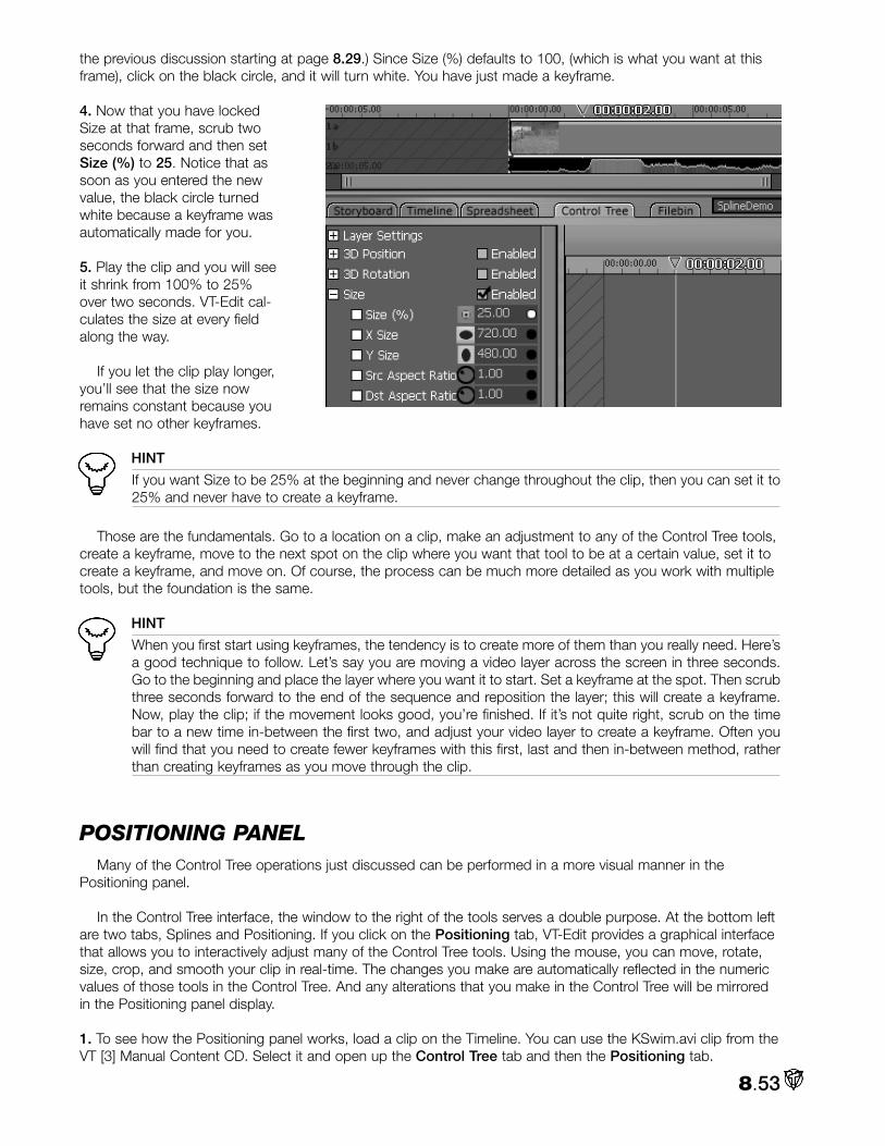
the previous discussion starting at page 8.29.) Since Size (%) defaults to 100, (which is what you want at thisframe), click on the black circle, and it will turn white. You have just made a keyframe.
4. Now that you have lockedSize at that frame, scrub twoseconds forward and then setSize (%) to 25. Notice that assoon as you entered the newvalue, the black circle turnedwhite because a keyframe wasautomatically made for you.
5. Play the clip and you will seeit shrink from 100% to 25%over two seconds. VT-Edit cal-culates the size at every fieldalong the way.
If you let the clip play longer,you’ll see that the size nowremains constant because youhave set no other keyframes.
HINT
If you want Size to be 25% at the beginning and never change throughout the clip, then you can set it to25% and never have to create a keyframe.
Those are the fundamentals. Go to a location on a clip, make an adjustment to any of the Control Tree tools,create a keyframe, move to the next spot on the clip where you want that tool to be at a certain value, set it tocreate a keyframe, and move on. Of course, the process can be much more detailed as you work with multipletools, but the foundation is the same.
HINT
When you first start using keyframes, the tendency is to create more of them than you really need. Here’sa good technique to follow. Let’s say you are moving a video layer across the screen in three seconds.Go to the beginning and place the layer where you want it to start. Set a keyframe at the spot. Then scrubthree seconds forward to the end of the sequence and reposition the layer; this will create a keyframe.Now, play the clip; if the movement looks good, you’re finished. If it’s not quite right, scrub on the timebar to a new time in-between the first two, and adjust your video layer to create a keyframe. Often youwill find that you need to create fewer keyframes with this first, last and then in-between method, ratherthan creating keyframes as you move through the clip.
POSITIONING PANEL Many of the Control Tree operations just discussed can be performed in a more visual manner in the
Positioning panel.
In the Control Tree interface, the window to the right of the tools serves a double purpose. At the bottom leftare two tabs, Splines and Positioning. If you click on the Positioning tab, VT-Edit provides a graphical interfacethat allows you to interactively adjust many of the Control Tree tools. Using the mouse, you can move, rotate,size, crop, and smooth your clip in real-time. The changes you make are automatically reflected in the numericvalues of those tools in the Control Tree. And any alterations that you make in the Control Tree will be mirroredin the Positioning panel display.
1. To see how the Positioning panel works, load a clip on the Timeline. You can use the KSwim.avi clip from theVT [3] Manual Content CD. Select it and open up the Control Tree tab and then the Positioning tab.
8.53

NOTE
When you are selecting your clip, be sure to select the video portion. If you hit the audio portion, thePositioning window won’t display anything because there is nothing to position.
2. Take a look around the panel, which is specific to the clip that you have selected. For example, the time barat the top displays the clip’s timecode, and it reflects the In and Out Points that you have set for that clip. Youcan scrub through the clip by dragging the blue triangle.
The thin blue line boxes are references maneuvering your clip or image. The outer blue box shows the edgeof the video frame; (it does not represent the edge of your clip). Anything positioned outside this box will not beseen on your TV monitor. The inner blue box delineates the Safe Action Area. If you position anything outsidethis box, it may be cut off on some TV monitors. (See Chapter 12 for more information on Safe Areas.) The lightyellow crosshair quarters the screen, with the intersection in the exact middle.
You can zoom on both axes of the display at once with the Zoom + and – buttons at the top right of thepanel.
If you change your clip to Overlay, then if Show All Layers is checkmarked, the clip above it on the Timelinewill be displayed. If the background clip is also an Overlay, then the clip above it also will be shown. And on andon if there are additional Overlays.
Your clip is surrounded by a thin white outline that has control circles in each corner and in the middle ofeach edge. When you roll your mouse over different areas of the clip, the cursor will change to indicate the toolthat is active at that spot. When you see one of the tools, you can click and drag your mouse to use it. Exceptfor Size, right-clicking will give you a different aspect of the tool. For example, right-clicking when Crop is active,will just crop one side and not the whole image.
8.54

3D Position
The cursor changes to Move when you roll anywhere inside of the white outline.
• Left-click + drag inside the video layer to move the layer on the X and Y axes.
• Shift + left-click + drag inside the video layer to constrain your movement to either the X or Y axis.
• Right-click + drag inside the video layer to move the layer on the Z axis.
3D Rotation
The cursor changes to Rotate when you roll anywhere outside of the white outline.
• Left-click + drag outside of the video layer to rotate the layer on the Z axis.
• Right-click + drag outside of the video layer to rotate the layer on the X and Y axes.
• Shift + right-click + drag outside of the video layer to constrain your rotation to either the X or Y axis.
NOTE
You can change your pivot point in the Control Tree by numerically adjusting the X and Y Centres (seethe 3D Rotation section starting on page 8.34).
Size
The cursor changes to Size when you roll over one of the control circles on the white outline.
• Left-click + drag on one of the corner circles to size the video layer proportionally on all sides.
• Left-click + drag on one of the circles in the middle of the left or right edge to size the width of thevideo layer.
• Left-click + drag on one of the circles in the middle of the top or bottom edge to size the height of thevideo layer.
8.55

Crop
When you roll over the outside edge of the white outline, that edge turns yellow and the cursor changes toCrop.
• Left-click + drag on the edge to crop the video layer proportionally on all sides.
• Right-click + drag on the edge to crop the video layer on just that edge.
Smooth
In the Control Tree, Smooth is found under Edges. When you roll over the inside edge of the white outline,that edge turns yellow and the cursor changes to Smooth.
• Left-click + drag on theedge to smooth the videolayer proportionally on allsides.
• Right-click + drag onthe edge to smooth thevideo layer on just thatedge.
When you alter Smooth,another white outline is createdthat indicates its boundaries.
8.56

Keyframing in the Positioning Panel
In the Positioning panel, you can quickly set keyframes for 3D Position, 3D Rotation, and Size. Let’s take asimple example of creating a picture-in-picture and moving it in the video frame over the length of the clip.
1. If you want to follow along, load KSwim.avi and BlueBkg.tga from the VT [3] Manual Content CD. Drag themon to the Timeline and put BlueBkg on a track above KSwim. In the Trim Bay, turn Overlay on for KSwim.Stretch the BlueBkg still out so that it is as long as KSwim.
2. On the time bar, scrub to the first frame of the clip, or press the Stop button to jump to the first frame.
3. Grab one of the corner control points on the clip’s white outline and reduce the Size of the KSwim clip toabout 50%.
HINT
You can look at the Control Tree tools to see what the numeric values are. If you enter a value in theControl Tree, it will be reflected in the Positioning panel.
4. Set any Cropping and Smoothing that you desire. If you want to add a Shadow, you will need to go to theControl Tree.
5. Move the clip off-screen to the left. After positioning it where you want, you need to create a keyframe forany setting that will change.
Keyframe Button
6. The Keyframe button is on the upper right of the panel, above the time bar. When you have set the videolayer at the first frame of your sequence, click on the button to highlight it.
8.57

If you look at your Control Tree display, you will see that keyframes are automatically set for the X, Y, and ZPosition (in 3D Position), for the X, Y, and Z Angle (in 3D Rotation), and for the Size (%) and X and Y Size (inSize). You can tell because the little black circle, (to the right of the data entry field), turns white.
Notice that keyframes are made even if you have not adjusted the tool, which, in turn, will allow you tochange that value later without having to backtrack. Also, note that keyframes were not automatically made forCrop or Smooth (Edges), even if you did change them from their defaults. If you plan to change Crop orSmooth again during the sequence, you need to set their keyframes by hand in the Control Tree by clicking inthe black circle to turn it white.
7. Now on the time bar, scrub to about a third of the way into the clip. This will be your next keyframe. Noticethat the Keyframe button has turned off. Move your clip layer to the top middle of the video frame. As soon asyou start moving it, the Keyframe light comes on, which indicates that the Positioning panel is automatically set-ting keyframes for you.
8.58

Remember that it is only setting keyframes for the 3D Position, 3D Rotation, and Size tools listed above.However, if you make an adjustment to Crop or Smooth at this location, a keyframe automatically will be made– if you had set a previous keyframe for it.
8. Scrub to your next spot on the time bar (about two thirds into the clip), move the clip layer to the right edgeof the frame. Keyframes are automatically made.
9. Scrub to near the end of the clip, move the clip layer to the middle of the frame, and resize it to full screen.You can do this quickly with the Reset button (see below).
NOTE
If you have changed Crop or Smooth, you will have to bring them back to their defaults in the ControlTree. Reset does not affect them.
To see the sequence, you can scrub it on the time bar, or simply play the clip.
10. You now have four keyframe spots, which are delineated on the time bar by thin purple vertical hash marks.(Look closely to see the first one on the left.)
11. To jump from keyframe to keyframe, click one of the arrows that flank the Keyframe button.
12. If you are at a keyframe and want to delete it, click the Keyframe button off. This will delete all thekeyframes for the 3D Position, 3D Rotation, and Size tools listed above at this spot on the clip. This action willnot delete any other keyframes at this spot. And the video layer will jump back on the time bar to its previouskeyframe.
Reset Button
The Reset button is on the upper right of the panel, above the time bar. When you click Reset, the X, Y, andZ Position (in 3D Position), the X, Y, and Z Angle (in 3D Rotation), and the Size (%) and X and Y Size (in Size)are all reset to their defaults, and keyframes are created for them at that location. You can click the Reset but-ton anywhere on the Positioning panel time bar. If there was a keyframe at that spot, it will be replaced with thedefault values; if there was no keyframe, a new one is created.
8.59

HINT
Most actions in the Positioning panel can be undone by hitting Ctrl + z or the Undo button at the top ofthe VT-Edit panel.
Spline EditorFor precise command of the Control Tree tools over a period of time, use the Spline Editor panel, which is
accessed by clicking the Splines tab at the bottom of the Control Tree window, to the right of the tools.
Spline Editor Interface
The Spline Editor interface is specific to the clip that you have selected. For example, the time bar at thetop displays the clip’s timecode and it reflects the In and Out Points that you have set for that clip.
1. Load a clip onto the Timeline. For this example, you can load MareFoal.avi from the VT [3] Manual ContentCD. Select it, go to the Trim Bay, and set the In Point to 00:00:00.10. If you look at the image above, you’llsee that the diagonal lines on the left stop at that spot on the time bar. The diagonal lines on the right indicatethe Out Point of the clip, which has been set to 00:00:16.12.
8.60

As with the Timeline interface, you can zoom in and out on the horizontal axis with the scroll bar at the bot-tom. You also can zoom on the vertical axis with the scroll bar on the right. You can zoom on both axes at oncewith the Zoom + and – buttons at the top right of the panel.
Nodes
The Spline Editor presents a graphical display of the values of the Control Tree items.
2. To see how it works, select a clip in the Timeline, (such as MareFoal), and scrub to the In Point on theSpline Editor.
3. In the Control Tree, click on the + in the box next to Size to expand it. In Size (%), enter 33. Now click inthe black circle to the right of it to create a keyframe for Size (%) at the In Point.
4. To see your handiwork in the Spline Editor window, click on the white box next to Size (%), which will changethe box to a circle with a black X in it.
Size (%) changes to an orange color, which also is the same color of the line placed in the Spline Editor win-dow.
5. If you look closely on the left at the beginning of the line under Size (%), you will see a little circle, which iscalled a Node. This node is how the Spline Editor indicates a keyframe.
6. To get a good look at a node, scrub to one frame before the Out Point of the clip.
HINT
If you set a keyframe right at the Out Point of your clip, you will not be able to see your clip on yourProgram Out monitor at that point. Since adjusting Control Tree tools often requires that you have a visu-al reference, if you set the keyframe one frame before the Out Point, you will be able to observe yourchanges.
7. Go back to the Control Tree and adjust Size (%) to 100.
HINT
Remember that you simply can double-click on the icon to the left of the number field to bring the valueback to its default.
8. The circle to the right of the number field should turn white, which means a keyframe was automatically set.
8.61

If you look in the Spline Editor, you’ll see your two nodes connected by a straight line.
That straight line indicates that from one node to the other, the change in Size (%) is linear – which means, inthis case, increases in Size (%) are equal for every frame. This linear formula for calculating change can workfine in many situations; but often, the change can seem abrupt, especially at the beginning and end of asequence. Or if you are moving a video layer through a number of keyframes, the movement won’t seemsmooth. To solve this problem, you use Influences.
Influences
In the Spline Editor, you control the formulas that dictate the change between nodes with Influences. Luckily,you do not have to worry about any math, because setting and tweaking Influences is a visual task.
1. To illustrate the power of Influences, let’s set up a fast, dizzying example. Load a still frame on to theTimeline. If you want to follow along, load ChineseDancer.tga from the VT [3] Manual Content CD. Select it,then go to the Trim Bay and set the Video Duration to 00:00:05:00.
2. Since this example only needs a few numbers entered, you can do it fairly quickly from the Control Tree. Let’sstart the sequence with the image at full frame. So scrub to the In Point; and in the Control Tree, set keyframesfor the X and Z Angle (in 3D Rotation), and the Size (%) (in Size). Since you want the default values, just clickon the black circle to the right of the number field to turn it white and create a keyframe. Do it for all three.
3. Now move to a second later on the time bar, set Size (%) to 50, then rotate 360 degrees on the X Angleand another 360 degrees on the Z Angle.
4. Move forward one second on the time bar. Rotate back on the X Angle to –360 degrees. Don’t change theZ Angle or Size (%) values, but create keyframes for both at this location.
5. Move ahead one more second and rotate back on the Z Angle to 0. Don’t change the X rotation. And bringSize (%) back to 100.
6. Play the sequence back and you’ll see a couple of abrupt transitions.
The changes are graphically indi-cated by the sharp angles in theSpline Editor, especially the X Anglelines. These can be smoothed outwith Influences.
What is a Spline?
So far, in the example above, ifyou look at the Spline Editor, youhave been creating Nodes that areattached to each other by straightlines. A Spline is a curve, so, inessence you have yet to create aspline until you attach Influences.But since this is the Spline Editor, itwill be less confusing if this repre-sentation of nodes and straight linesis called a spline.
8.62

Adding an Influence
You can add an Influence in the Spline Editor in four ways.
7. Click on the Influence button at the top of the panel. (Clicking it toggles off the Node button.) Now, in theSpline Editor window, when you roll your mouse near a spline, your cursor will have a little x attached to it, indi-cating you are in Influence mode. Also the spline will brighten, which means that you have selected it. Whenyou click anywhere on that spline, an Influence point, again indicated by an x, will be created at that spot.
Or
With the spline selected, if you double-click anywhere in the Spline Editor, an Influence will be created at thatspot, and it will be attached to the selected spline.
Or
You also can scrub the Edit Line until it intersects the spline, and then hit the m key, and an Influence pointwill be created at the intersection.
Or
If you are in Node mode, you can add an Influence by holding down the Ctrl key and clicking.
HINT
If you are having trouble distinguishing between different splines, (especially whenthey are overlapping in the Spline Editor), go to the Control Tree and toggle off anyof the items that are in the way. Simply, click on the box with the X next to the tool.
8. To return to the previous example, create two Influence points on either side of thesharp X Angle transition at 1 second into the clip.
9. To smooth out the angle, grab the Influence point on the left, and then pull it up andaway from the spline.
Notice that you are making a curve out of the straight line. Congratulations, you have offi-cially made a spline.
10. Grab the Influence point on the right, and then pull it up and away fromthe spline.
The little displayed numbers show your location on the scale. 359 means359 degrees in this case, since this is the X Angle.
11. When you play the sequence back, the spin slows as it gets to thatkeyframe or node, and remains slow as it leaves. This is called easing in andeasing out.
You commonly apply Influences to splines to adjust movements, but they can be used in a myriad of ways.
8.63

Adding a Node
You can add Nodes to splines the same way that you add Influences. To create a new Node, click on theNode button at the top of the panel, and then click anywhere on the spline. Or if you are not on the spline,double-click and the spline will jump to the Node’s position and attach to the Node. Or move the Edit Line so itintersects the spline where you want the Node, and hit the n key.
Adding Multiple Nodes or Influences
To add Nodes to all the splines that are visible in the Spline Editor, scrub the Edit Line to where you want toadd the Nodes, and then hit Alt + n. To add Influences, hit Alt + m.
Selecting a Spline
Select a spline by rolling your mouse over it. You will see it brighten, and itsspline tag in the lower left of the window will be discernibly lighter than the otherspline tags.
One spline will always be highlighted in the Spline Editor, (the spline closest tothe mouse).
Selecting Nodes or Influences
The quickest way to select a Node or Influence is to click on it. You need to bea little careful because if you miss your object and click on the spline instead, youwill create a new Node or Influence, depending on which mode you are in. Toassist you, your cursor changes to a little four-headed arrow when you are over aNode or Influence.
Usually, as you are rolling around the Spline Editor, your cursor will have a little dotted box at the end of thearrow. This means that your mouse is in Selection mode. If you click and drag the mouse, it will draw out aselection box.
Any Nodes or Influences inside the box will be select-ed. You also can select multiple Nodes and Influences byholding down Ctrl while clicking.
To select all the Nodes and Influences for the selectedspline, hit Ctrl + a. To select every Node and Influence forevery spline visible in the Spline Editor, hit Alt + Ctrl + a.
Editing Nodes or Influences
You can adjust a Node’s value by dragging it up or down in the Spline Editor. For example, if you draggedthe X Angle spline up or down, you would be increasing or decreasing its value in degrees. As you drag it, theposition on the scale will be displayed numerically next to the Node.
NOTE
The scale on the Spline Editor will change depending on the spline that is selected. For example, if youselect the X Angle spline, then the numbers on the left side of the Spline Editor will represent degrees ofan angle. If the X Size spline is selected, then the numbers will represent pixels.
You can adjust a Node’s position on the Timeline by dragging it left or right. You cannot drag it past anotherof the spline’s Nodes without unwanted results.
HINT
To constrain the movement to either up and down or left and right, hold down the Shift key when youare dragging the mouse.
8.64

You can adjust an Influence in the same manner. If you are dragging it left or right on the Timeline, youshould not move it past a Node. And the spline looks a little weird if you try to move an Influence past anotherInfluence on the Timeline.
If you have selected more than one Node or Influence, then you can drag them together. You can dragNodes and Influences from more than one spline. And if you have selected multiple splines, you can drag all ofthose around at once.
WARNING
As you see, editing Nodes and Influences is easy – maybe too easy, because even slight changes canradically alter your sequences. Luckily, the Spline Editor, like the rest of VT [3], has a multiple Undo fea-ture, so you can experiment and then hit Ctrl + z or the Undo button to back out of any undesired resultsor miscalculations.
Reset Button
The Reset Button at the top of the Spline Editor will reset any Node or Influence back to its default value. If youselect the Nodes for all the splines at one moment in the Timeline, you can Reset all the values back to theirdefaults, (which can be useful if you want to restore a clip back to its original state). Since you can select multipleNodes, this button can be a pretty powerful tool. In the wrong hands, it can flatten a perfectly nice rolling spline.
Deleting Nodes or Influences
To delete a Node or Influence, select it and then either hit the Delete key on the keyboard, the Delete buttonat the top of the Spline Editor, or Ctrl + x. If you have multiple items selected, you can delete them all at once.
Navigation Tools
To jump from one Node or Influence to the next on aselected spline, you can hit the arrows that flank theKeyframe button at the top of the Spline Editor panel. Oryou can use the keyboard shortcuts. Hitting the F1 func-tion key on the keyboard easily accesses the following listof shortcuts for the Spline Editor.
Copying and Pasting Nodes and Influences
You can copy and paste Nodes and Influences withina spline, or even between splines.
1. Highlight a spline, and then select the Nodes andInfluences that you want to copy. Hit Ctrl + c to copythem.
2. Now, scrub the Edit Line to the location on the splinewhere you want to paste them.
3. Hit Shift + Ctrl + v to paste the Nodes and Influencesat the scrub line.
4. If you want to paste them into another spline, select it and repeat steps 2 and 3. Of course, the splinesshould be compatible – that is, copying X Angle values to the Y Angle spline and not to the Size (%) spline.Though, you might imagine an odd combination like adjusting a Volume spline, and then applying it toBrightness or Hue.
NOTE
Usually, you paste Nodes and Influences after the last one that’s already on the spline, but you can pastethem anywhere on the spline with interesting results.
8.65

Playback Speed
As was mentioned earlier, setting keyframes for the Playback Speed tool in the Control Tree is a specialcase, because the spline must be created prior to setting any In and Out Points for the clip in your project.(Let’s just say, if a clip was in the Timeline and you animated its speed to zero, you could set the Timeline rip-pling to infinity.) To explain how to adjust Playback Speed safely in your studio, let’s ramp the speed of a clipfrom full speed down to half and then back up again.
1. If you want to follow along, load MareFoal.avi from the VT [3] Manual Content CD into an empty spot on theTimeline, where it’s not in Ripple contact with other clips. Drag the Out Point of your clip to twice its normallength. For MareFoal, the normal Video Duration is 17 seconds and 4 frames, but it’s extended to about 35seconds. Ignore the warning icon that says you are past the end of the clip
2. Open up the Control Tree and expand Layer Settings to reveal the Playback Speed tool. Scrub to the InPoint of the clip; in Playback Speed, create a keyframe at the default of 100.
3. Now setting the other keys isn’t an exact science as you’ll see. In this example, the spot where the horseswill slow to 50% speed is the moment when they turn, (about 8 ½ seconds into the clip). Scrub to that spotand adjust Playback Speed to 50%.
Play the clip. You’ll notice that at 8 ½ seconds into the clip, the horses have not reached the turnaround.That’s because you have slowed the clip and it takes longer to get there.
4. So, in the Spline Editor, drag the Node on the Playback Speed spline to the right until you see the horses turn, (inabout 12 seconds). Remember, if you hold the Shift key while you drag, you constrain your movement to one axis.
5. If you want them to speed back up to 100% at the end of the clip, then scrub to the end and create akeyframe there, at about 28 seconds.
Play the clip back. You probably guessed that the horses reach the end of the clip before the speed ramped allthe way up.
8.66

6. Grab that last Node and move it back to where you see the clip end, in around 23 seconds.
HINT
When you’re dragging Nodes, make sure that you don’t have unwanted ones tagging along.
If you want to add other keyframes, you can see how you may have to realign Nodes with points on the clip.
When you have set the speed ramp, you can add other splines, such as for movement. Then adjust your Inand Out Points to select the part of the clip that you want and insert it into your project. Just remember, if youwish to readjust your Playback Speed spline, you should take the clip out of the Timeline, make your changes,and then put it back in.
Spline PresetsVT-Edit provides a powerful and flexible tool to save and apply favorite splines. For example, you may be
producing a project that requires you to pan and scan a series of fifty photographs in the same manner. If youcould create the movement once and then apply it to all of the photos, it would be a tremendous timesaver.
To Apply a Default Spline
1. Select your clip(s).
NOTE
Spline Presets can be applied to multiple clips all at one time.
2. At the top of the VT-Edit panel, click on the Tool Shed button. Then click on the box next to Presets toexpand it, and open Default Splines.
3. From the list, select one byclicking on the name to highlight itin blue. For example, choosePsycho In or, if you’re not in theHitchcock mood, try Plain BlueBorder.
4. In the Apply Range Start andEnd fields, you pick the part of theclip on which you will be applyingthe spline.
8.67

Start
• In Point – The Spline will be applied starting at the clip’s In Point.
• Current Time – This value can be used for either Start or End, though not for both at the same time.Current Time is indicated by where the Edit Line is placed on the clip.
• Clip Start – This is the beginning of the clip. Even if your In Point is set a few seconds into your clip, ifyou choose Clip Start, the spline will be applied beginning here.
End
• Out Point – The application of the spline will be will end at the clip’s Out Point.
• Current Time – Current Time is indicated by where the Edit Line is placed on the clip.
• Clip End – This is the end of the clip. Even if your Out Point is set a few seconds earlier in your clip, ifyou choose Clip End, the application of the spline will end here.
Mode
• Preserve – Only those spline nodes that fall within the time interval specified by Start and End areapplied. The distance between the nodes is preserved.
• Scale – The length of the spline increases or decreases to fully fit into the interval of time specified byStart and End. When scaling starts at the In Point, the spline is scaled around the In Point. When scalingstarts at the Clip Start, the spline is scaled at the Clip Start point. If your Start choice is Current Time,then the spline is scaled at the Out Point or the Clip End, whichever is selected in the End choice.
5. Click Perform and play the clip to see the effect.
If you click on the box next to the spline title, you can see what Control Tree tools are used.
NOTE
The Default Spline parameters areprovided for informative purposes. Ifyou try to alter them, the changes willnot be saved. Of course, if you openthe Control Tree and select the clip,you can see the exact settings andyou can tweak the clip’s splines thathave been created by applying thepreset.
To Store a Spline Preset
1. The real power of spline presets is the abil-ity to create and store your own splines sothat you can recall later or share with othereditors. To begin, create your effect, whichmay consist of multiple splines.
2. Open the Tool Shed; click on Presets and User Splines.
8.68

3. Click New, and type in a title for yourpreset. Hit Enter to store it in the UserSpline Preset list. It’s that easy. When youwant to reuse it, select a clip, highlight theUser Spline, adjust your Apply Range set-tings, and hit Perform.
HINT
If you hold down the Shift key whenyou click New, you will only storethe splines that are currently visiblein the Spline Editor. Therefore, youcan separate the general splinesthat you want to save as a Presetfrom other splines that may be spe-cific to the clip you are working on.
4. When you are naming your Presets, try to title them with a uniquely descriptive name. It will help you in thefuture after you have stored a long list of Presets.
5. If you are in the sharing mood, User Spline Presets are stored in the directory called VT3/User Data/”my username”/Spline Presets/. The names have a .VT Spline Preset extension.
Panning and Scanning Still Frames
Since VT-Edit can import images on to the Timeline that are bigger than video resolution, you have theopportunity to move the image around the frame in a technique called pan and scan. The Positioning panelmakes this process fast and fun. And with the ability to store spline presets, you can zip through repetitive tasksfairly painlessly. But there are a couple of tricks that will make the process even smoother.
First, you should understand how to resize images that you import into VT-Edit. As was mentioned earlier,VT-Edit takes oversized images and scales them down so that the largest dimension fits on the screen. Forexample, if you load Calypso.jpg from the VT [3] Content CD, which is 1500 x 2000, it is scaled to 24.3% Sizeto be visible on the screen. If you want access to its full resolution, you must set Size (%) to 100. Now, you cantake it into the Positioning panel and move it around or zoom in and out on that cute face.
8.69

HINT
If you load a small resolution clip or image, you can size it exactly to fit the screen by setting Size (%) to100, X Size to 720, and Y Size to 486 (for NTSC) or 576 (for PAL). This will stretch the image and dis-tort it (if it wasn’t originally in a 4:3 format).
The second, not so obvious, trick to using still frame addresses with how they are seen in the Control Tree.By default, when you load a still, it comes onto the Timeline as a five-second clip. (You can change this defaultin the Preferences panel under EDITING: General > Default Still Length.) This default length is also reflectedin the Control Tree time bar.
This becomes important if, for example, you create a pan and scan of a still that is five seconds long; andthen you decide you would like to add three more seconds after that five seconds where the image doesn’tmove. Now, if you just go to the Timeline and move the still’s Out Point, you actually stretch the clip. If you lookin the Edit Properties, the clip’s Speed is now 62.5%, which means that the pan and scan has been stretchedand slowed to fill the whole eight seconds. But you don’t want to do that.
You can extend the In or Out Points of a still without affecting the Speed, by going into the Edit Propertiespanel and making the adjustments at the In and Out Point windows.
Or if you hold down the Alt keywhile dragging the Out Point, the cur-sor will change from Stretch to Out,and the still’s Out Point will be extend-ed.
8.70

Overlays
Working with Overlays is an essential technique when you are creating multi-layered effects such as picture-in-pictures, (PiP). Normally, you will construct your Overlay stacks in the Timeline and adjust the clips in theControl Tree. Let’s make a simple PiP to show you the basic steps.
1. In the Timeline load two clips or stills. As always, if you want to follow along, you can load WaterChurning.rtvand BirdRock.avi from the VT [3] Content CD. Put the background clip, WaterChurning, on a track above theforeground, BirdRock. Turn Overlay on for the foreground clip, BirdRock.
HINT
The quickest way to turn Overlay on for a selected clip is to use the keyboard shortcut of pressing y.There’s also an Overlay check box in the Trim Bay and the Edit Properties panel.
2. Now, in the Control Tree’s Positioning panel, shrink BirdRock to about 50%, smooth the Edges to about10, maybe even adjust the Alpha a little. And play the sequence.
3. One of the restrictions of Overlays is that you cannot fade them in and out with the traditional Cross FadeDVE. Actually, you can’t apply any DVEs to an overlay on the Timeline.
8.71

NOTE
You can apply DVEs to Sub-Projects. So if you create a Sub-Project with an overlay, you will be able touse a DVE on the Sub-Project as a whole. (For more information on copying and pasting overlays intoSub-Projects, see page 8.75.)
4. To simply fade an Overlay in or out on the Timeline, moveyour mouse to the bottom corner of the video track of the clip.The cursor will change to Fd for fade.
If you click and drag the edge of the clip when you see Fd,you will create a Fade In, (if you are dragging into the clip fromthe front). Or you will Fade Out if you are dragging into theclip from the back. The numbers displayed as you drag arebased on the timecode of the clip.
5. If you want precise controlof the fades, you always cancreate an Alpha spline in theControl Tree. Notice that thefade you make in the Timelineis not reflected in the Alphasettings for that clip in theControl Tree.
6. Of course, if you want moreimages floating around, youjust add layers on top of lay-ers. Remember, VT-Edit readsvisibility from the bottom of theTimeline up. The lower layeralways covers the one on top.Or conversely, the backgroundimages are above the fore-ground images on theTimeline.
7. Inevitably, if you stackenough layers on top of eachother at one time, even thefastest, meanest machine willwhimper. But since VT-Edit willbackground render, often bythe time you are finished con-structing your multilayeredmasterpiece, VT-Edit will beready to play it back.
8.72

Sub-ProjectsA Sub-Project is like a project within a project. It is a great way to organize your bulky projects into manage-
able segments. When you create a Sub-Project, VT-Edit collapses the scenes and transitions into one crouton.You can also make Sub-Projects within Sub-Projects.
To Create a Sub-Project
1. Perhaps the easiest way to select the clips for a Sub-Project is to click on the Timeline with your mouse anddrag a box around them. They, of course, have to be next to one another or overlaying.
2. Then, you can either click the Sub Project button on the top left of the VT-Edit panel, or right-click anywhereon your selection; and from the Context Menu, choose Create Sub-Project. The Storyboard makes one Sub-Project crouton, and the Timeline creates a separate segment labeled Sub Project. You can give the SubProject an Alias by clicking in the Trim Bay and entering a new name.
Sub-Projects in the Storyboard
In Storyboard view, your Sub-Project appears as a separate crouton with a + in the corner. To expand aSub-Project crouton, click on the + and you can see the contained croutons will spill out. The Sub-Project crou-ton remains on the Storyboard, but now with a – in it’s corner.
8.73

To collapse a Sub-Project, click on the – in the corner to hide the croutons, and display only the Sub-Projectcrouton.
When you expand the Sub-Project, you can still see the rest of your project, however the croutons for yourSub-Projects scenes are smaller. This can get confusing, so you have the option of drilling into the Sub-Project.
When you drill, you move down to a view that shows only the scenes in the Sub-Project. The Path displaybeside the VT-Edit tabs shows your location in the project tree. Drilling is the same as moving around a filedirectory; think of each Sub-Project as a folder within a folder.
8.74

To drill into a Sub-Project, select the Sub-Project icon, right-click on it and choose Drill into Sub-Project.Or Shift + double-click on the icon.
To back out of the Sub-Project only view, click on the name of the Sub-Project in the Path display. VT-Editwill back out of the Sub-Project and display the icons of the entire project. (The Sub-Project icons will be col-lapsed when you do this, so you will not see their individual scenes).
Sub-Projects in the Timeline
In Timeline view, your Sub-Projects appear as a solid bar. You can move this bar around, but you must drillinto the Sub-Project to work on specific scenes. The process to drill into a Sub-Project on the Timeline is thesame as for the Storyboard.
Global Changes to a Sub-Project
One of the big advantages to creating a Sub-Project is your ability to apply Color Correction to the Sub-Project as a whole, which applies those adjustments to every clip in the Sub-Project. If you select a Sub-Projectand open up the Control Tree or the Edit Properties panel, you can see the Color Correction tools available toyou. You even can scrub through a Sub-Project and set keyframes along the way, and then go to the SplineEditor and adjust the spline. If you select the audio track of the Sub-Project, you also can perform globalchanges to all the audio clips in the Sub-Project.
Inserting an Overlay in to a Sub-Project
Sometimes, you may want to attach one clip to another clip so that they always stay together. For example,if you have a clip of a speaker and another of the sign-language interpreter translating the speech, you canresize the interpreter clip to fit in the speaker’s frame, and then make it an Overlay.
1. Select the clip that you want to overlay, resize it, and make any other changes.
2. Press y to activate the Overlay.
3. Right-click on the Overlay clip and choose Copy.
4. Right-click on the clip where you want to place the Overlay, and choose Paste Into Subproject as Overlay.
Adding Clips Into a Sub-Project
You can insert new clips into an existingSub-Project option. They will be added tothe end of the last clip in the Sub-Project.
1. Right-click on the clip or clips that youwant to add to the Sub-Project and chooseCopy.
2. Right-click on the Sub-Project and choosePaste Into Sub-Project.
8.75

InheritOccasionally you will make changes to a clip, (for example, shorten it or resize it), and then decide that you
want to replace it in the Timeline or Storyboard with another clip. With the Inherit feature, when you drop thereplacement clip on top of the original, the second clip acquires the properties of the original. So, in this case, itwould have the same length and size as the first.
Inherit lets you make placeholder clips for scenes that you have not shot yet. You set the timing, position, orother options on the placeholder clip and continue editing. When the replacement shot is ready, you just holddown the Alt key and drag and drop it onto the placeholder to inherit the placeholder’s settings.
To Inherit Settings
1. Right-click on the replacement clip and choose Copy.
2. Right-click on the original clip and choose Paste Into (Inherit). The filename will modify to read Drop Inheritto remind you of the action about to take place.
Or
1. Click to select the replacement clip.
2. Hold the Alt key as you drag and drop it onto the original clip.
In both cases, the original clip disappears as the new clip replaces it.
NOTE
Inherit works best with clips that are the same type. For example, RTVs inherit well from other RTVs.Some of the clip properties may be lost when you Inherit across types, for example, RTVs inheriting fromAVIs or a video clip inheriting from a still image.
You also need to understand the consequences of Inheriting. It’s a comprehensive transfer of properties. Forexample, if you have set In Point and Out Points on the original clip, the Inherited clip takes those settings. This is agood thing and works as it should, but it may require you to readjust some points after you have Inherited the clip.
If you just want to reproduce some of the characteristics of the original, you will have specific control by cre-ating Spline Presets from the first clip and applying them to the second. (For information on Spline Presets, seepage 8.67.)
Tool ShedThe Tool Shed is an ever-expanding storehouse of practical editing tools, which is accessed by clicking on
the Tool Shed button in the middle of the top of the VT-Edit panel. With its popup help menus, the Tool Shedwas designed to be explored. Future VT [3] software updates will have additional new tools that will improveyour workflow.
8.76

To show you the simple power of some of the tools, let’s first talk about Markers.
Markers
Markers are handy little green gadgets that you can place anywhere on a clip to indicate things like possibleedit points. You usually insert Markers by selecting and playing a clip, and hitting the m key every time you wantto add a Marker.
Markers and music are a great mix. Try this for some fun.
1. Load a piece of music on to your Timeline.
2. Double-click the music to play it and place Markers by tapping m to the beat. To move a Marker, roll your mouseover its chubby bottom and the cursor will become an M, which indicates that you can click and drag the Marker.
To delete a Marker, move the Edit Line over it, right-click on it, and then select Remove clip marker (at edit line).
3. If you don’t have perfect syncopated rhythm, open the Tool Shed and expand the Marker section.
4. Open Quantize and follow the instructions.For more information, click on the ?. If theMarkers don’t hit the beat exactly, go back tothe Timeline, select them all and nudge them tomatch.
5. Now that your beats are even, open Wizardsand select Cut to Music. This magical little toolcan cut clips to music faster than you can sayHogwarts.
6. If you selected a music clip over 30 secondslong, you probably need at least ten clips, whichyou can find by opening the Filebin, clicking theHotlist key, and choosing the Effects Folder.Then open the Solid Colors folder. Inside are amultitude of Technicolor stills waiting to tango.Pick more than you need and load them ontothe Timeline.
HINT
Remember if you Ctrl + click, you can select the order that the clips load into the Timeline andStoryboard.
7. Now, select the music clip and hit Perform. Abracadabra. The clips jump to the Markers. If you loaded toomany clips, select the extras and delete them. But wait, there’s one more rabbit to pull out of the hat.
8.77

8. In the Tool Shed, go to the DVEs section and click Add DVEs. This tool will add a DVE between every clipthat you select in your project. So, back to the Hotlist, open your DVE Folder and pick a favorite transition.Pick one appropriate to the music, and drag it onto an empty spot on the Timeline. Perhaps choose somethingas subtle as DVE_7075.
9. Select the DVE; back in the Tool Shed, hit the Grab DVE button. The DVE’s name should be displayed in thepanel. Enter a Duration if you want some time other than the default.
10. Under Apply Range, pick Whole Project and hit Perform. Play the sequence and sing-along. If you don’tlike the DVE, pick another one; and in the Add DVE panel, make sure you check Replace Existing DVEs.
8.78

SPREADSHEETThe tab in the VT-Edit panel that has been ignored in this chapter is the Spreadsheet. Just the name can
send cold shivers through the artist in you. And at first glance, the Spreadsheet panel loaded with a long projectlooks like something only an accountant could love. But if you inspect it more closely, you’ll see that it is chockfull of information about your clips and the project as a whole.
Even though the Spreadsheet looks a little like your Filebin when it’s set to Details Icon view, you need toremember that the Spreadsheet is just another view of your project. To that extent, you can select and moveclips or DVEs up or down the list, just like you would in the Storyboard. You could actually edit In and OutPoints by entering new values. If you are working on a deposition and the lawyers gave you instructions for cut-ting the video to timecode, this Spreadsheet method could be the quickest way of editing the clips.
The real power of the Spreadsheet is in its ability to manage files. Forexample, you finished a project and cleared your hard drives of all theclips. Six months later, your client comes back and wants somechanges. You Batch Capture the project again, but this time all the clipsare on your V drive instead of the Z drive where they were originally. Yousimply reload the project and open the Spreadsheet. Pick all the clipsthat you need to relocate, and right-click on the first clip in the Drivecolumn.
In the Context Menu, choose Edit Drive and enter V, if that’swhere the clips are. When you click Enter, all the clips that you haveselected will change to V. Now, what do you think of the Spreadsheet?
8.79

HINT
To browse to a clip’s new location, click in the Drive or Path column and a three-dotted button will appear.Click on it to open a version of the Filebin. You also can modify the look of a Spreadsheet as you can aFilebin. (For more information on changing configurations, see Chapter 5.)
FILE MENUThe quiet unassuming File Menu houses some important project management features.
AVI WrapperVT [3] provides a method of handling VT-Edit projects so that they don’t need to be rendered before they are
loaded into other programs. This AVI Wrapper allows you to consolidate a complex project into a singlemetafile, which can be imported into any application that can read AVI video files. In the AVI Wrapping process,two files are written to the hard drive that point to your source audio and video clips: [file].avi and [file].VT EditProject. While the .avi file can be moved to another location on the computer, it looks for the VT Edit Projectwhere it was saved. As a result, the VT Edit project file saved as the .avi companion cannot be moved. If it is,the AVI will fail to locate any of the project’s assets.
NOTE
If you delete any of the project’s assets from your hard drives, obviously the project won’t be able to play-back properly. If you do need to delete assets, then first Render your project out as an AVI. (The processof rendering a project is described on page 8.83.)
With this AVI wrapper, you now can save your VT-Edit projects directly as an .avi file. When loaded in anotherapplication, such as Digital Fusion, AfterEffects or Premiere, the project will load as a contiguous file. This istremendously beneficial for DVD authoring, since encoding or authoring software requires a single file to createa DVD-compliant stream.
NOTE
AVI Wrapper Audio CaveatFor VT [3] to wrap audio into an AVI file without rendering it, it relies on the fact that Windows has some-thing called the Audio Compression Manager (ACM.) This allows applications to use an audio codec tocompress their audio. VT [3] has an audio project codec that allows VT-Edit to simply place the projectdata into an AVI file; then the codec finds the files referred to in this project and renders the correct sec-tions of audio when requested by the host application.
The one problem here is that many applications fail to fully support ACM. There are many applications thatcan only read uncompressed audio from an AVI file, and so the VT [3] audio wrapper codec will not be readcorrectly into these applications.
8.80

Saving a VT-Edit Project as an AVI
To save your project as an AVI, simply click on File and Save As. In the File Requester, name your file; andunder File Type, choose *.avi. Hit Save and your project is now wrapped as an AVI file that can be directlyloaded into other programs that accept AVIs.
You can reload the .avi file into VT-Edit, and it will open up just like any other VT-Edit project – with all the lay-ers and assets as they existed.
Save and Save AsThese two buttons work like they do in every other panel in VT [3]. But when you are saving a project, you
will be asked about Undo/Redo Stacks.
Undo/Redo
When you save a project, VT-Edit asks: Keep Undo/Redo Stack? When you save the Undo/Redo Stack, VT[3] remembers everything you did in your project, and saves a small file on your hard drive. This means you canshut down VT [3], return the next day, and undo an action.
Undo/Redo Stacks are also helpful if you have a system crash. The stacks for a project automatically arestored in a folder with your project’s name. That folder is in the same Projects folder that contains the VT-Editproject. Since each Undo/Redo Stack has a time and date, you can manually load a particular Undo/RedoStack to look at the state of the project at that time. Undo/Redo Stacks load into VT-Edit just like a project file.
The Undo and Redo buttons in VT-Edit make editing a lot simpler because they allow you to rectify your mis-takes; and more importantly, you can experiment with your project. Click the Undo button if you move an itemby mistake or if you just want to eliminate changes that you made. (The common keyboard shortcuts for Undo,Ctrl + z, and Redo, Ctrl + y, work in every VT [3] module.)
Redo will redo what you undid. So if you hit Undo and decide that you actually want to keep the changeyou erased, you can hit Redo. Note that Redo works only when you do not make new changes after you hitUndo. (To paraphrase Cole Porter, who do the redo that you undo so well?)
NOTE
You can hit Undo as many times as necessary to return to the status before your changes. You set theUndo number in VT-Edit in the Preferences panel under EDITING: General > Maximum Number ofUndos. The default is 100, but you can set it to Infinity if you plan on living that long.
8.81

Print to Tape Project…Clicking Print to Tape Project… opens a panel that allows you to record your project directly to videotape
with precise timecode accuracy. Print to Tape is essential when you want to cut a new sequence into a pro-gram on a master tape, or if you need to begin recording your program at an exact time on the tape (such as00:00:00:00). Of course, your videotape recorder must be capable of frame accurate edits for this feature tofunction properly. If you have such a machine, then many of the controls on this panel will look familiar.
1. To begin, load a project into VT-Edit. If you only are recording a portion of the project to tape, you could trimit here, but you also can trim in the Print to Tape panel.
2. You must be connected to your videotape recorder, both with audio and video cables and deck controlcables. See Chapter 6 on Deck Control for more information on setting up your system.
3. Click on File and select Print to Tape Project…
4. In the panel under Source Preset, choose the deck. When you insert your tape, the deck control displayshould be reading the tape’s timecode.
5. The Project windows on the right are very similar to the In and Out Point windows in the Edit Propertiespanel. By default, the In Point is set to 00:00:00:00, which corresponds to that point on the Timeline. If for yourproject, you place color bars, a slate and a countdown before 00:00:00:00 on the Timeline, then you will needto adjust the In Point setting.
By default, the Out Point is placed at the end of the project. If you only want to record part of the project,then you would reset the In and Out Points accordingly. The windows give you a visual reference when adjust-ing the points.
6. If you have a specific time length to fill on the tape, then you can set a Duration, which will alter the OutPoint to fit the time. If you hit Lock, then when you adjust either In or Out, the clip will Slip and Slide. Changingthe Offset value alters the In Point, and vice versa.
7. Above the deck controls are two mini-panels for setting the In and Out Points on the videotape. If you knowthe exact timecodes, you can type them in. Or you can play the tape until you find the In Point, then click onMark. If you have a specific Out Point, follow the same procedure in the Out Point mini-panel. The Go to InPoint button simply shuttles the tape to that spot.
8.82

8. Next, you need to select your record options. If you checkmark Assemble, (for an Assemble edit), all yourother choices become inactive. If you are making an Insert edit, then you can choose what part of the projectyou will record: Timecode, Video, Audio 1, or Audio 2.
9. The Preroll time for the deck should have been selected when you went through the deck control set up. Tocheck it, click on the C next to the name of your deck and you’ll see a Preroll entry field. If it’s not right, changeit and hit Add to save the change.
NOTE
With some decks, you can open up the Advanced panel on the VT [3]’s Deck Control interface and selectPreroll settings.
10. When everything is right, you can push Rehearse to test the settings without actually recording. Whenyou’re assured, click on the Print to Tape button to start the recording.
Render Project…Rendering basically takes a snapshot of your project and creates a video or audio. You can render an entire
project, a Sub-Project, or individual clips to a file.
1. To render the current project, click File and Render Project…, which brings up the Render panel.
NOTE
You can render a selected time range or clips directly from the Timeline by right-clicking on a clip andchoosing Render Selected Time Range… The Render panel that pops up is the same one that isdescribed in these steps.
8.83

2. At the top of the panel, click on the three-dottedbutton next to the Name field. In the File Requester,browse to the location where you want to place the fileand give it a name. The File Type suffix will be appliedaccording to the codec that you choose later. ClickSave to close the File Requester. The path and newname should be displayed in the Name field.
3. In the three boxes next to the Name field, you canchoose to render the Video, Audio or Alpha portionsof the project. If you only choose Alpha, you render afile that uses a key shape, so part of the image is com-pletely transparent and the other part is completelyopaque. You essentially render a silhouette with all of itsmovement but with no details. (If for any reason youwant to keep video details, you need to render Videoand Alpha.
4. You set the beginning and end of the project that you want to render in the Start Frame and End Framewindows, which work like the In and Out Point windows in the Edit Properties panel described earlier. The win-dows give you a visual reference when adjusting the frames. Click the R button next to the timecode slider toReset to the timecode of the original Start or End Frame.
5. In the Speed box, you can adjust the playback speed of the project. A setting of 50% will play the projectback in slow motion at half speed. If the original project were five minutes long, the final rendered project wouldbe 10 minutes long. This setting does not change the project, only the speed it is played. Click the R buttonbeside the Speed field to Reset to the default speed.
6. In the box to the right, you pick the Video Codec. Many of thevideo codecs are described starting on page 7.2. Notice that youalso can render out still image sequences in a variety of types. Ifyou are not rendering video, choose No Video.
7. Click on the C (Configure) button (next to the arrow) to automati-cally configure the codecs with their optimized settings.
With some of the codecs, like WindowsMedia Video, clicking theC button will pop up a panel of configuration options.
8. The number of choices you have in the Resolution menudepends on the Video Codec that you selected. When you pick aResolution, it will be reflected in the FPS and Pixels boxes next toit.
9. Often when you pick a Video Codec, the compatible AudioCodec will pop up. Many of the Audio Codecs are described onpage 7.5. If you have not checked the Audio box at the top, itdoesn’t matter what you enter here since you are not renderingaudio. Click on the C (Configure) button, (next to the arrow), toautomatically configure the codecs with their optimized settings.
10. As indicated in the Sample Rate menu, the lower the SampleRate, the lower the quality of the audio.
11. When all the settings are correct, click Render and a Render Progress window will pop up. When the ren-der is complete, the window will disappear and your file is ready.
8.84

NOTE
You can render a project directly from the Filebin without ever opening VT-Edit. Just browse to your pro-ject’s folder and right-click on the project file. Choose Render/Convert and the Render panel pops up.Of course, you must create a project in VT-Edit so that you have a project file to use.
VT [3] is now allowed to render FASTER than real-time if your computer supports it. You will get the bestresults if you render to a different drive from your video source footage to avoid disk thrashing. For this speedenhancement to work, the Preview Rendering on Output feature was disabled since it would not allow ren-dering to go faster than the output could go, which is 29.97fps. If you want to see every frame that was ren-dered, you can re-enable this option in the Preferences panel under EDITING – General.
Batch Capture Project…If you have a project that contains clips that you originally batch captured, but since deleted from your hard
drives, you still can load the project on to the Timeline. The missing clips will be grayed out and the audio trackwill have a red border.
1. To restore the project, click on File and Batch Capture Project…
2. The Batch Capture Manager panel will pop up andprompt you to insert the tape that contains the first miss-ing clip. When you insert the tape in your deck, clickStart Capture, and the Batch Capture will begin. If youneed to insert other tapes, you will be prompted. (Formore information on the Batch Capture process, turn topage 7.12.)
3. When all the clips have been captured, your projectwill be restored.
NOTE
To Batch Capture individual clips in a project, select them on the Timeline and then right-click to bring up theContext Menu. Choose Batch Capture Selected Clips… and the same Batch Capture Manager will pop up.
Import… (EDLs, Tape Logs)If you or a client has generated an EDL (Edit Decision List) from
another editing software, you can import it into VT-Edit by selectingImport… (EDLs, Tape Logs) from the File menu.
From the dialog box that pops up, you choose what type of filethat you want to import: an Edit Decision List (.EDL), a Comma-separated Spreadsheet (.CSV), or a basic Text Log (.TXT).
EDLs may import on to the Timeline as one big Sub-Project that you will have to drill into to open up. (Seethe discussion on Sub-Projects on page 8.73) Then, open the Spreadsheet panel and examine the EDL. If youhave the video and audio clips on your system, you still may have to guide the Spreadsheet to the location of
8.85

those clips. Simply, click on the Path column for the file and a three-dotted icon will appear. Click on it and aFile Requester will open. Browse to the file and click Select.
If you don’t have the clips, but the EDL has Batch Capture information for them, then you can select a rangeof clips and right-click on one of them. From the Context Menu, choose Batch Capture Selected Clips… Orif you wish to Batch Capture the whole project, click on File and select Batch Capture Project… (See the pre-vious section for information on Batch Capturing on page 8.85.)
Cut, Copy, Paste, and DeleteIf you need to get rid of a clip or you want to duplicate a clip, use the buttons at the top of the panel. Cut
will copy an item while deleting it from its current location. Copy lets you copy an item, and also keep the clip inits original location. Paste will paste the items that you cut or copied at the insertion point where you place yourmouse. Delete will delete an item from the work area; no copy is made.
These four functions also can be accessed by right-clicking on a clip and selecting the operation from theContext Menu; but probably the simplest way is to use the common keyboard shortcuts:
Cut – Ctrl + xCopy – Ctrl + cCopy – Ctrl + vDelete – Delete key
NOTE
These actions only affect clips in Storyboard or Timeline mode, not on your hard drive. So if you delete aclip from the Storyboard or the Timeline, the clip is still available on your hard drive. However, if you deletea clip from the Filebin, you do delete that clip on your hard drive.
You can cut, copy, paste, or delete from the Storyboard or the Timeline. To select multiple items, Shift +click to select a contiguous range of clips and effects; Ctrl + click to select items non-contiguously.
In the Storyboard, if you select the croutons in a specific order and cut or copy them, they are pasted backin that same order. In essence, you are making a mini-project out of the selected croutons, which are pastedtogether.
In the Timeline, when you select clips, they are not affected by the order that you select them. Timeline clipskeep their positions relative to each other. Paste works slightly differently depending on whether the active paneis a Timeline or a Storyboard. Pasting to the Timeline pastes elements at the current time marker. Pasting to theStoryboard inserts the elements after the last selected crouton, or, if no crouton is selected, after the last crou-ton. The Paste Buffer is global, so you can copy/paste between projects. If the croutons are in the Storyboard,a standard ripple operation occurs. If the clips are in the Timeline, the project will ripple if you have Rippleenabled.
The Delete button clears all of the selected croutons from the project.
8.86

The Switcher is the core VT [3] component for producing live video. With the Switcher, you can combine amultitude of visual sources – live cameras, videotape decks, digital disk recorders (DDRs), CG pages, graph-
ics – with Digital Video Effects (DVEs) in real-time. Working with the Audio Mixer, you can add a variety of audiosources like live microphones and recorded tracks. And if you have an SX-8, you can input up to 24 camerasand eight stereo audio inputs.
If your computer system is muscular and your hard drives are speedy, these events can be captured in real-time to your video drives. You also can output to a video tape recorder or video projector, or even stream live tothe Internet.
HINT
If you don’t have an SX-8, you can still produce a dynamic show with only one live camera and a lot ofrecorded clips. And even though you may never plan to mount a Switcher show, it’s wise to be familiarwith the Switcher because it is the router for video in VT [3].
Basic Switcher Setup1. Load the Switcher from the Production Desk section of the Main Menu. For this chapter, select the 8Input skin. If it doesn’t automatically come up, right-click on the Switcher panel to open the Context Menuand choose it from the list of Available Skins.
2. To give us visual content, open a DDR from the Main Menu. Usually, the DDR will load into one of the PatchBays of the Switcher. If you don’t see DDR listed, right-click on an available Patch Bay. Under ComputerGenerated Video Sources, select Digital Disk Recorder.
3. In the DDR panel, click Add Media and load MEyes.tga, which came on the VT [3] Manual Content CD.
4. Open a second DDR. Again, check to see if DDR2 is in a Patch Bay. If not, on the upper right of this DDR
9.1
Chapter 9: Switcher & RS-8

panel is a DDR2 tag. Click and drag the tag onto an available Patch Bay. (This is another way of addingsources onto the Patch Bay.)
NOTE
Depending on previous configurations, the DDRs may not be labeled DDR and DDR2. Whatever the num-bers, adding them to the Patch Bay is still the same.
5. On DDR2, Add Media. This time, find and Open GEyes.tga.
6. Now, open a VT-Vision monitor from the Main Menu. On the bottom row of buttons, click on PGM.
Switcher and VT-Vision
VT-Vision was designed to let you monitor the video selected on your Switcher busses. When you are using theSwitcher, you should have at least one open on your desktop – more than one if your computer can handle it.
At the bottom of the VT-Vision panel, in the middle, are fiveinput choices. You click on the one that you want to monitor.Three of them mirror the Switcher busses (discussed below):Prev (Preview), Main, and Key. DSK (DownStream Keyer) isanother function performed with the Switcher. And when youwant to see the final output, you select PGM, (Program Out).
Program OutOne of the ways to understand how the Switcher works in VT [3] is through the concept of Program Out,
which is the video and audio signal that VT [3] outputs through the back of the card. The Switcher determineswhat that video signal is and routes it out the card. The Audio Mixer handles the audio signal.
Program Out can be a single source like a live camera or TEd, or it can be a combination of sources like aDDR clip composited over a live camera with a CG bug in the corner. You organize and perform functions likethese from the Switcher interface.
SWITCHER INTERFACEThe Switcher provides three choices of Normal skins. You can display the Switcher with eight channels for
your Main, Preview, and Key busses, or you can display larger versions with 16 or 24 channels. If you right-clickover an empty area of the panel, you can select your skin from the Context Menu that appears. You also canclick on the S in the right corner of the panel to cycle through all the available skins. (In this chapter, the 8 Inputskin will be the reference.)
Busses
On the left side of the Switcher are three rows (banks) ofbuttons called busses. Each row is labeled above it. From thetop, the Switcher has a Key bus, a Main bus, and a Previewbus. Each bus has a specific function. You can route video tothe busses through the row of inputs above the busses calledPatch Bays.
Main Bus
The Main Bus is the middle row. If you are doing a live show, whatever is on the Main bus is LIVE, whichmeans it is being outputted from the Switcher, often in combination with other video sources. The video can beanything that you have patched to the Switcher, ranging from a live camera feed to a CG title page.
9.2

You select the Main source by clicking its channel number in the Main bus. To monitor what is on this bus,set VT-Vision to Main.
Preview Bus
The source that sits on the Preview bus is next in line to go LIVE. Select your Preview source by clicking onits channel number in the Preview bus.
Setting up a Take Transition 1. Working from the setup above. Load DDR into the Main bus by clicking the number below it on the middle,(Main), bus. The number will light up and you should see the video clip in DDR on the VT-Vision set to PGM.
2. Load DDR2 into the Preview bus by clicking its corresponding number in the bottom, (Preview), bus.
3. Open a second VT-Vision and set it to Prev, allowing you to see what is on the Preview bus.
4. The most basic transition is a Take, in which you instantly replace one source with another. In the middle ofthe Switcher panel is the Take button. Click on it and the Preview source, DDR2, jumps to the Main bus andDDR switches to Preview. Click Take again and they switch back.
You also can perform a Take by hitting Enter on the keyboard.
Setting up a Dissolve 5. If you haven’t loaded any DVEs into the Effects banks on the right of the Switcher panel, the default transitionis a Dissolve (or in VT [3] terms, a Crossfade).
9.3

To activate a Crossfade, click on the Auto key, (next to Take). In your VT-Vision set to PGM, you should seethe image on the Main bus fade away as the image on the Preview fades in, finally replacing it totally.
You also can perform the transition by hitting the Spacebar on the keyboard or by double-clicking on thehighlighted number in the Preview bus. The Tab key will automatically set the Switcher for a Crossfade, regard-less of which transition has already been selected.
HINT
If you hit Auto (or the Spacebar) during a transition, the effect will pause at that spot. To resume the tran-sition, hit Auto or the Spacebar again.
9.4

Now, to reverse the transition, hold down the Shift key and hit Auto (or the Spacebar). You can reverse thetransition at any time.
Key Bus
The Key bus lets you overlay or key one video source on another when you use the VT [3] keyers or titles.For more detailed information and specific examples of keying, please refer to Chapter 13: Chroma and LumaKeying.
Lock Key
In the middle of the Switcher panel is a Lock Key option thatis explained more thoroughly in Chapter 13. For now, leave itcheckmarked, which will put any source that you place on thePreview bus onto the Key bus.
Adding Sources to the SwitcherThere are three common ways to add a source to the Switcher. If you have opened a panel like a DDR, click
on the panel tag (for the DDR, it’s in the upper right), drag it, (as you hold your mouse button down), and dropinto a Patch Bay slot in the Switcher. You can drag and drop sources from most VT [3] panels.
You also can right-click on the tag to bring up its Context Menu. Any of the options under Commands willplace the source in the Switcher.
NOTE
If your Switcher is filling up with sources, when you add another by using one of these Commands, youmay not see it pop up on your Patch Bay. It’s there, but to access it, you will need to pick an expandedSwitcher skin, like the 16 or 24 Input ones.
The most direct method of adding a source is to right-click on a channel in the Patch Bay and select fromthe list of available sources.
NOTE
The Patch Bay channel does not need to be empty toadd a source to it. Whatever you drag and drop orright-click into it will replace what was there.
Also, if you have an SX-8 attached to your system, youcan double-click on an empty Patch Bay channel and launchthe Virtual BOB panel, where you can drag the input into theSwitcher.
Usually, when you add a source to the Switcher, it is auto-matically placed on the Preview bus. You can change thisaction, though. On the Preferences panel, under OtherModules, choose the New Modules option. If you chooseShould not be placed on Preview row, the new sourceswill go into an available channel, but won’t activate any bus.
Bus Dots
The Patch Bay channels use color-coded dots to indicateif their source is active on a bus. The tag on the panel of thissource will also reflect the color-coding scheme.
9.5

• A red dot shows the source on the Main bus• A green dot shows the source on the Preview bus• A yellow dot shows the source on the Key bus• A purple dot shows the source on the DSK
In the example above, when DDR2 was on the Preview bus, a green dotappeared beside DDR2 tag in the Patch Bay and on the DDR2 panel. If youhave checkmarked the Lock Key option, the yellow dot indicates the sourceis also on the Key bus.
NOTE
A Warning symbol, known as a “bang,” on a channel indicates that the source is not avail-able. For example, if you close the DDR2 panel and that panel was patched to the Switcher,you would then see a warning sign in the corner of that Patch Bay tag.
Deleting Sources1. Click to select the source tag in the Patch Bay of Switcher.
2. Keep the mouse over the Switcher and press Delete on the keyboard.
3. A message appears that asks Remove selected patches from Switcher? Click on OK to delete or click onCancel if you’ve changed your mind.
WARNING
To protect your Program Out, you cannot remove an input that is active on the Switcher – that is, anyinput selected on the Main, Preview or Key bus.
Rearranging Sources on the Patch BayYou can shuffle the placement of your sources on the Switcher by dragging and dropping the tags onto
another channel. When you change the order, the bus attached to your tag, (if there is one), stays with it. So ifyou had a DDR in channel 1 that sat on the Main bus, and you moved the DDR tag to channel 5, it would stillbe on the Main bus.
Here are the redecorating rules:
• If you are moving a tag that is active (on the Main, Preview, or Key bus) onto a channel that has an active tag, the two tags will switch channels.• If you are moving an active tag onto a channel that has an inactive tag, the active tag will remove the one from the Switcher.• If you are moving a inactive tag onto a channel that has an active tag, the two tags will switch channels.
1. You also can rearrange tags by clicking on the tags and dragging them onto an empty area of the VT [3]desktop. Inactive tags will vacate their spot on the Patch Bay, so make all the tags you want to rearrange inac-tive.
2. When you have cleared your Patch Bay, go to your desktop and click on the tags in the order you want themon the Patch Bay. As you click, they will fill in the empty Patch Bay channels from left to right. Of course, if youdon’t want one of the sources back on the Patch Bay, just don’t select it.
3. If a tag has a Warning sign on it, then you will have to drag it back to the channel on the Patch Bay.
9.6

4. To clean up your desktop, click and drag a box around the tags on the desktop to select them all. Now,right-click on the desktop and from the Context Menu, under Desktop Utilities, choose Remove Icons(Selected) – Delete.
NOTE
By default, the Switcher will always map the current Main, Preview, and Key selections to the visiblebusses. Thus when you close the Switcher and open it again, you will see the sources that you last usedalready set to Main, Preview, and Key.
Black Source
The Switcher offers a Black Background that you can load and use to fade to and from black. To add aBlack Background, right-click on a channel, under Computer Generated Video Sources, choose BlackBackground. Or hit B on the keyboard to set Black as the Preview source.
T-barIn the middle of the Switcher panel, the T-bar serves two purposes.
First, it is a visual representation of the progress of a transition. So whenyou hit the Spacebar to engage a transition, the T-bar will automaticallymove from top to bottom. But you also can grab the T-bar with yourmouse and you manually control the speed and direction of a transition.
1. Working from the setup at the beginning of the chapter, DDR is on theMain bus and DDR2 is on the Preview. Again, if you have no effectsloaded in the Effects bin, the default transition is the dissolve (Crossfade).
2. When you roll the mouse near the T-bar, the cursor changes to a bi-directional arrow (up and down). The T-bar defaults to the up position.
9.7

To begin the transition, move the T-bar down by clicking your mouse button on the T-bar and holding as youdrag. You can move the T-bar as slowly or as quickly as you like. To monitor your progress, look at the VT-Vision monitor set to PGM.
4. You can stop pulling at anytime. To do a partial dissolve, release the mouse at an intermediate point. Or youcan reverse directions. Or if you want to make your audience seasick, waggle the T-bar back and forth.
5. If you double-click the T-bar, it will jump to mid transition and stay there. If you are using a DVE like1036_Wipe, you will create an instant split-screen.
6. To complete the transition, pull the T-bar all the way down. (Or simply hit the Spacebar on your keyboard orthe Auto button on the Switcher panel.) When you release the mouse, the T-bar will jump back to the top.
TakeThe Take button performs an instant cut between the Main bus and Preview bus. A cut is simply a jump
from one source to another, for example from one camera shot to a different camera shot. Remember that tocut between your selected shots, the shot you want to be next must be on the Preview bus.
Pressing Enter on the keyboard also will perform a Take.
Or you can perform an instant Take by clicking on another channel in the Main bus. For example, if DDR ison the Main, DDR2 is on Preview, and the Black Background is on channel 6, you could cut directly to Black byclicking on the 6 button in the Main bus.
Auto
Clicking on the Auto button triggers the T-bar to apply the current transition at a selected speed. (You alsocan hit the Spacebar on your keyboard to engage the transition.) The Auto button illuminates and stays illumi-nated during the transition. When the action stops, the light goes off.
HINT
You can pause the transition by clicking the Auto button or the Spacebar and begin it again by hittingthe Auto button or the Spacebar. Performing a Take on any paused clip will reverse the Program andPreview sources at their current positions on-screen.
Controlling Transition Speeds
1. To the right of the T-bar, on the bottom of the Switcher panel are a rowof three speed buttons, S, M, F (Slow, Medium, or Fast). To change thespeed of a transition, click on one of the buttons.
With a Crossfade transition, click on S and. The dissolve should takeabout two seconds.
2. You can change speeds in mid transition. Hit the Spacebar to start a slow transition. Before it ends, click onthe M button and the transition will continue at the Medium speed.
Speed Gauge
3. Just above the S, M, F buttons, the Speed gauge lets you manually adjust transition speed. Place the mousein the Speed gauge and the cursor changes to a bi-directional arrow.
Drag the mouse to the right to increase speed or to the left to decrease it. (The speed is displayed in sec-onds and frames. For example 2.04 = two seconds and four frames.)
You can adjust the speed as the transition is running. For example, set the transition to 4 seconds, hit theSpacebar to start it, and then drag the mouse to the right. The transition will speed up.
9.8

Repeat
4. Checkmark the Repeat option above the T-bar. Hit the Spacebarand as soon as the transition finishes it will repeat until you hit theSpacebar again.
Reverse
5. Uncheck Repeat and checkmark the Reverse option above it.When you engage the transition it will play backwards. With someDVEs, like the Crossfade, you will see no significant difference.
As with other transition controls, you can alter Reverse in mid-airby unchecking it as the transition is occurring.
DVES – DIGITAL VIDEO EFFECTSVT [3] comes bundled with a bunch of butt-booting, brain-boggling DVEs – hundreds of ‘em. In the past,
some systems have differentiated between transitions and DVEs. Transitions were simple dissolves or wipesthat did not move the actual video picture, while DVEs were digital effects that manipulated the video picture. InVT [3], all transitions are digital transitions, and so the terms transitions and DVEs are used interchangeably. TheDVEs in VT [3] are realtime effects; they don’t need to be rendered when placed on the Switcher.
(Appendix C contains a description of each DVE and the icon associated with it.)
Locating the DVEsWhen you install the DVEs, you can choose the directory where you want them placed, or they are installed
by default in C:\Content\DVEs. Within that folder are several categorical drawers for different types of DVEs,ranging from Curls to Borders. And lurking inside are enough DVEs to land you in hot water with the Eye Candysquad including Stampeding Sheep (7012 - a truly baaaaad DVE).
NOTE
The full DVE directory can take up a lot of hard drive space. If you don’t have enough on your C drive,then install it on a more accommodating drive. Engineering says a peppy, 7200 rpm IDE drive should befine. Be sure that your DVE Root Path in the Preferences menu is correct.
Previewing DVEs
You can preview any DVE without loading it into theSwitcher.
1. Open a File Bin from the Main Menu, (set it to Large Iconview), and browse to the DVE directory.
2. Open a folder, like 2000_Curls. The DVEs all use animatedicons. In its frozen state, the icon shows an illustration of theDVE action. But the icons are AVI files, so if you hover themouse over a DVE icon, you will see the DVE make a transi-tion from a colorful VT1 foreground to a VT2 background.
HINT
If you are trying to conserve system resources, in thePreferences panel (Files > Rollover AnimatedPreviews), turn off icon animation by selectingDisabled.
9.9

Adding a DVE on the Switcher1. The Effects busses lets you easily access DVEs for switching. On the 8 and 16 Input Switcher skins, theyare opened by clicking on the Effects tab on the right side of the Switcher panel. On the 24 Input skin, theEffects busses run across the top of the panel.
Start with the basic setup. On the 8 Input skin, click the Effects tab to display the 15 Effects busses.
2. Double-click on an empty bus to launch the File Requester. Browse to the DVE directory. Open the3000_trajs folder. If you double-click on your desired DVE, it will load into the bus. Pick 3020_tumble.dve.(You also could drag and drop the DVE. Or click to select and then hit the Open button.)
3. Of course, if you wish to load more than one DVE from a folder, you can hold the Ctrl key while you areclicking and then drag and drop them all at once. (The order in which you select them will be the order that theywill load into the busses.)
Go back to the 3000_trajs folder and round up four more DVEs and load them. Now the first row of theEffects bus is full.
HINT
If it’s not already there, place the DVE directory in your Hotlist so you can jump right to it when you openthe File Requester. For information on adding a directory to the Hotlist, see Chapter 5.
9.10
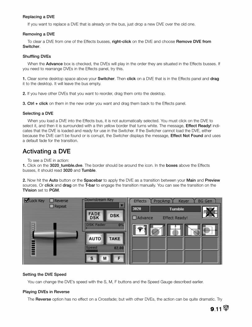
Replacing a DVE
If you want to replace a DVE that is already on the bus, just drop a new DVE over the old one.
Removing a DVE
To clear a DVE from one of the Effects busses, right-click on the DVE and choose Remove DVE fromSwitcher.
Shuffling DVEs
When the Advance box is checked, the DVEs will play in the order they are situated in the Effects busses. Ifyou need to rearrange DVEs in the Effects panel, try this.
1. Clear some desktop space above your Switcher. Then click on a DVE that is in the Effects panel and dragit to the desktop. It will leave the bus empty.
2. If you have other DVEs that you want to reorder, drag them onto the desktop.
3. Ctrl + click on them in the new order you want and drag them back to the Effects panel.
Selecting a DVE
When you load a DVE into the Effects bus, it is not automatically selected. You must click on the DVE toselect it, and then it is surrounded with a thin yellow border that turns white. The message, Effect Ready! indi-cates that the DVE is loaded and ready for use in the Switcher. If the Switcher cannot load the DVE, eitherbecause the DVE can’t be found or is corrupt, the Switcher displays the message, Effect Not Found and usesa default fade for the transition.
Activating a DVETo see a DVE in action:
1. Click on the 3020_tumble.dve. The border should be around the icon. In the boxes above the Effectsbusses, it should read 3020 and Tumble.
2. Now hit the Auto button or the Spacebar to apply the DVE as a transition between your Main and Previewsources. Or click and drag on the T-bar to engage the transition manually. You can see the transition on theTVision set to PGM.
Setting the DVE Speed
You can change the DVE’s speed with the S, M, F buttons and the Speed Gauge described earlier.
Playing DVEs in Reverse
The Reverse option has no effect on a Crossfade; but with other DVEs, the action can be quite dramatic. Try
9.11

to be tactful with this one, because the effect of a transition in reverse can look completely wrong in somecases. A few DVEs will not play in Reverse.
You also can hold Shift and click Auto while a DVE runs to force it to play in reverse. On the keyboard, Shift+ Spacebar has the same effect.
Controlling DVEs with the T-bar
If you’re a hands-on sort of person, you can manually control speed and direction of the transitions with theT-bar as explained above.
DVE QuickCall The boxes just below the Effects tab are called the DVE QuickCall area. The name of each DVE includes a
specific four-digit code (for example 7065_UFO.dve). When you enter a DVE code in the box, the Switcherretrieves your DVE without you fishing through the File Requester.
NOTE
There is a minor anomaly when entering the DVE code in the QuickCall box. Usually, after you type innumbers in a data field, you can hit Enter to exit the box. But since Enter has a specific function on theSwitcher, you will need to click on an open area of the desktop to exit the QuickCall box.
All DVEs must be unselected in the Effects bus and Advance must be Off. You then hit the Spacebar (orAuto) and the Switcher uses that DVE for a transition and will continue to use it until you change the number orselect a DVE from the Effects bus. To return to the default dissolve, just Delete the number in QuickCall.
The DVE codes were implemented for Edit Decision Lists (EDL), which use the four-digit codes to referenceeffects in a video project.
Starting a DVE with the Right Mouse Button
Right-click on the DVE in the Effects bus to bring up the Context Menu. When you choose your speed,[Launch DVE (Slow), Launch DVE (Medium), or Launch DVE (Fast)], the transition will occur.
Advancing DVEs
1. Checkmark Advance to sequentially move through the DVEs that you have loaded into your Effects busses.Assuming that you still have the five DVEs from the earlier example, hit the Spacebar to start a transition.
2. When the transition is over, VT [3] willmove to the next DVE in the Effects panel(left to right, and then down). The currentDVE will have the white border around it.Click the Spacebar again and that DVEwill play and then proceed to the next.
3. The Switcher will continue to progressthrough the DVEs as long as Advance isactive. When it reaches the end of theDVEs, it will cycle back to the beginning.
9.12

HINT
You can begin at any DVE. Simply click to select it. The Advance will start with it and proceed from there.
NOTE
For the Advance feature to work, make sure the path to your DVE folder is correct in the Preferencespanel under DVE Root Path.
Switcher Keyboard Shortcuts Like some of the other VT [3] panels, the Switcher comes with a variety of Keyboard Shortcuts or Hotkeys,
that are too numerous to list here.
Usually, you can call up the pages of Hotkeys by hitting the F1 key. But F1 is a Keyboard Shortcut in theSwitcher – it loads channel 1 onto the Main bus. So, you have to right-click to bring up the Switcher’s ContextMenu and under Help, choose Keyboard Shortcuts.
Often when you are live switching a show, you will have other panels open that have their own set ofHotkeys, like a DDR. To ensure that the Switcher’s Keyboard Shortcuts have priority, turn on Caps Lock. AsAussie says, “I used Caps Lock On, because it often has an LED light on the keyboard. Think of that light as‘Live or On Air’ - meaning, Switcher wins.”
The Hotkeys can be lifesavers when you are trying to work the Switcher in a fast- paced, high-pressure livepresentation. For example, one hand can be on the keyboard selecting inputs, while the other can be choosingDVEs with the mouse. Having Hotkeys literally at your fingertips will make you much more proficient.
NOTE
To assist you, the manual has a pullout page listing the Keyboard Shortcuts for all of the panels.
DSKDSK stands for the DownStream Key. Keying is
the process of combining or superimposing twoimages. Think of the Switcher as taking multiplesources of video into it, mixing them together, andflowing the stream out. The DSK applies a keysource over your video, downstream after youhave performed the dissolves and DVEs or addedchroma or luma keying. The Downstream Keyer ismost commonly used to apply graphics or titles,(like those omnipresent TV network bugs).
The controls for the Downstream Keyer are in the middle of the Switcher panel.
9.13
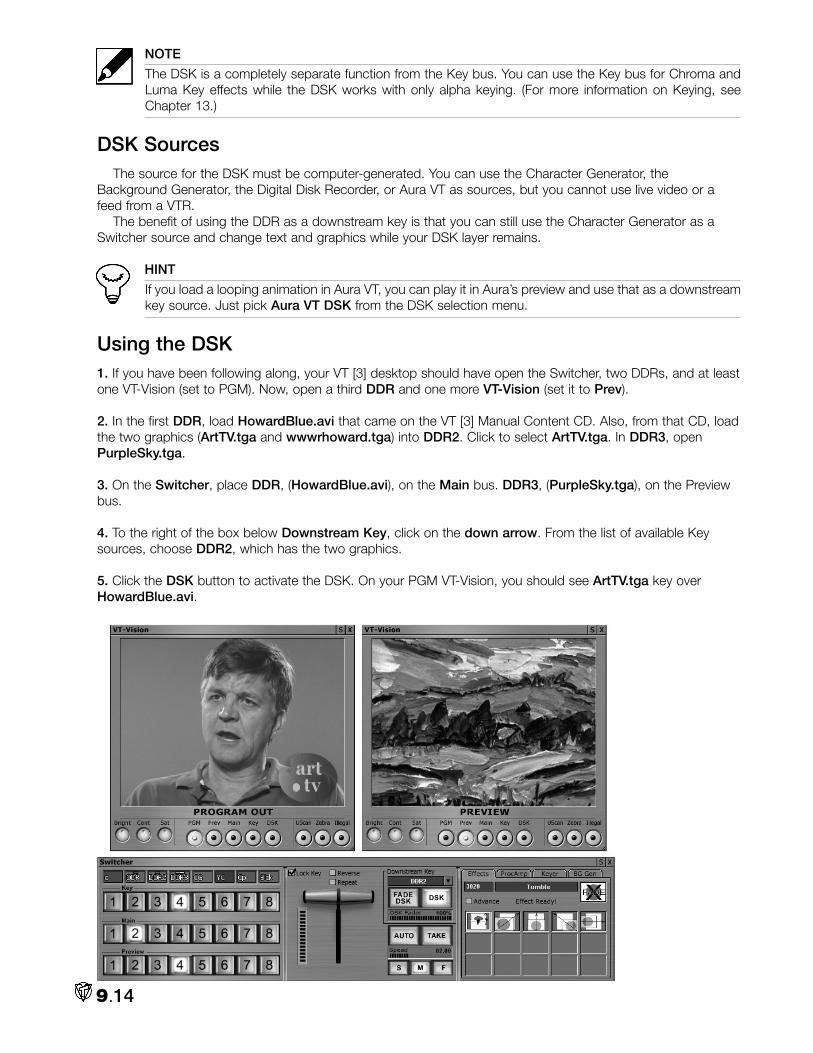
NOTE
The DSK is a completely separate function from the Key bus. You can use the Key bus for Chroma andLuma Key effects while the DSK works with only alpha keying. (For more information on Keying, seeChapter 13.)
DSK SourcesThe source for the DSK must be computer-generated. You can use the Character Generator, the
Background Generator, the Digital Disk Recorder, or Aura VT as sources, but you cannot use live video or afeed from a VTR.
The benefit of using the DDR as a downstream key is that you can still use the Character Generator as aSwitcher source and change text and graphics while your DSK layer remains.
HINT
If you load a looping animation in Aura VT, you can play it in Aura’s preview and use that as a downstreamkey source. Just pick Aura VT DSK from the DSK selection menu.
Using the DSK1. If you have been following along, your VT [3] desktop should have open the Switcher, two DDRs, and at leastone VT-Vision (set to PGM). Now, open a third DDR and one more VT-Vision (set it to Prev).
2. In the first DDR, load HowardBlue.avi that came on the VT [3] Manual Content CD. Also, from that CD, loadthe two graphics (ArtTV.tga and wwwrhoward.tga) into DDR2. Click to select ArtTV.tga. In DDR3, openPurpleSky.tga.
3. On the Switcher, place DDR, (HowardBlue.avi), on the Main bus. DDR3, (PurpleSky.tga), on the Previewbus.
4. To the right of the box below Downstream Key, click on the down arrow. From the list of available Keysources, choose DDR2, which has the two graphics.
5. Click the DSK button to activate the DSK. On your PGM VT-Vision, you should see ArtTV.tga key overHowardBlue.avi.
9.14

6. Use the Take and Auto buttons to switch at will between the images on the Main and Preview busses. TheDownstream Key should remain over each source and the transitions between the sources.
7. To remove the Downstream Key, click the DSK button off.
Fading the DSK
8. Select wwwrhoward.tga in DDR2 and then click on the FADE DSK but-ton. On your PGM VT-Vision, you should see the DSK source fade up overyour video. When the fade is complete, the FADE DSK button turns off andthe DSK button lights.
9. To control the speed of the fade, you can use the same S, M, F buttonsthat control the DVE’s speed. Just click on the speed that you want andthen click FADE DSK. You also can manually adjust the speed in theSpeed Gauge.
NOTE
You cannot use a DVE to remove the DSK. You must either click DSK off or fade away the DSK with theFADE DSK button.
Creating a Semi-transparent DSK10. Below the FADE DSK button is a DSK Fader gauge. Notice that when you click the FADE DSK button, theDSK source fades up to 100 percent. If you want a semi-transparent Downstream Key, you can manually dragthe DSK Fader gauge to the desired percentage.
With both the FADE DSK and DSK buttons off, click and drag your mouse in the DSK Fader gauge. Bring itto 50%. Now, click the DSK button. On your PGM VT-Vision, you should see the DSK source pop up over yourvideo at 50% transparency.
You can either hit DSK to pop it off or click FADE DSK to fade the downstream key away.
9.15

11. If you want to fade the DSK in to a certain transparency, that’s a little trickier. Click on the DSK button andthe DSK Fader gauge goes to 100. Manually drag the gauge back to 1%. (If you go to 0, the DSK button willturn off.) The key is basically not visible. Now, you can drag the gauge back to your target percentage and thefade will be visible.
HINT
Step 11 is a kludge – an inelegant solution – and won’t really work in a live switch situation. If you knowthe amount of transparency you want, you can build it into the graphic when you are creating it (seebelow). Then you can simply fade the DSK on and off with the FADE DSK button.
DSK Shortcuts
DSK shortcuts can make your workflow more efficient. Use the following keys on your keyboard to performactions with the DSK:
•D is the keyboard equivalent to the DSK button.
•F is the keyboard equivalent to the FADE DSK button.
•S is a combination of the TAKE and DSK buttons. Hit S to activate or deactivate the DSK source at thesame time that you cut between Main and Preview.
•A is a combination of the AUTO and FADE DSK buttons. Hit A to fade the DSK source up or down atthe same time that you dissolve between Main and Preview. You may wish to first press the Tab key topreselect a Crossfade. This gives the appearance that your key is locked to the source as they both fadeon or off at the same rate.
Creating DSK GraphicsYou can make your own DSKs in VT [3]’s Character Generator or in your favorite paint program like Aura.
Here are a few guidelines.
1. Since the DSK works by reading the alpha information of the key graphic, your graphics need to be saved as32-bit images, (tif, tga, or png). The background for the image must be transparent so the Program Out videoshows through. (The Character Generator, Aura, and many paint programs provide a transparent backgroundfeature.)
2. Make your graphics 720 x 486 pixels if you are working in NTSC, (720 x 576 for PAL). If you want to make alittle bug for the corner of the screen, start with a transparent 720 x 486 background and create the bug thesize and at the location that you want. Remember to allow for the video safe areas. (See Chapter 12.)
3. Since the DSK is sensitive to alpha channels, you also can add shadows in your graphics, which will be visi-ble over Program Out.
4. Load the image into your DDR and then into the DSK, and you’re in the bug business.
Chapter 12 on the Character Generator includes a step by step on making the ArtTV.tga..
Switcher’s Tabbed Panels
On the right side of the 8 and 16 Input Switcher skins are four tabs that bring up mini-panels for Effects,Proc Amp, Keyer and Background Generator functions. Even though the last three have their own separatepanels, they are included on the Switcher interface for improved workflow. (For more information on the Keyer,Background Generator, and the Proc Amp, see Chapters 13, 15 and 17.)
9.16

SWITCHER CONTEXT MENUThe Context Menu for the Switcher panel contains many of the common functions found in panel menus, like
the ability to Load and Save panel configurations. This means that you can add sources to the Switcher andsave those sources in a file that you can load later.
Switching from the Panel Tags Context Menu
If you right-click on a VT [3] panel tag, the Context Menu provides a list of Switcher Commands. These actionsare especially useful during live switching when you want to move quickly between inputs as you create them, andbypass the Switcher interface.
•Place Item in Switcher: Places the input in the next available channel on the Switcher.
•Perform Take to this input: Performs a cut from the current Main input to your selection.
•Perform Auto to this input: Performs a dissolve from the current Main input to your election.
•Put onto Main In: Replaces the current Main input with your selection.
•Put onto Preview In: Replaces the current Preview input with your selection.
•Put onto Key In: Replaces the current Key input with your selection.
•Put onto DSK Out: Places your selection into the DSK.
Using Multiple Cameras
Unless you have the SX-8, you only can input one live camera into the Switcher. With the SX-8, you canhook up 24 cameras. But you can see only two camera sources at one time while using the Switcher: thesource on the Main bus and the source on the Preview bus. You can change the cameras for Main or Preview.For example if Main was set to camera 1 and Preview was set to camera 2, you could change Preview to cam-era 3. But you still will only see two sources, (cameras 1 and 3).
If you want to see the signals from more than two cameras, you can create a splitter system from the SX-8.(See Chapter 2 for a more detailed explanation.)
Switcher and Live Internet Streaming
Live streaming to the Internet gives you a worldwide audience for your content – you can broadcast lectures,presentations, and other events to millions of viewers on the Web, or you can stream preliminary footage foryour client’s approval across town or around the world.
You use the same inputs for Internet streaming as you do for any live switching like cameras, microphones,VTRs, and the Character Generator. You switch and mix those elements in VT [3] and then encode the videoand send it through Windows Media Player, or another encoder, to the Internet.
For information and procedures on using VT [3] for streaming media, see Appendix B: Streaming Media.
9.17

Capturing from the SwitcherIf your computer system is muscular and your hard drives are speedy, you may be able to record your
switching directly to your video hard drives. For example, you could set up on the Switcher a Chroma Key withthree sources that you want to include as a clip in a VT-Edit project.
1. Set up your Switcher configuration.
2. From the Main Menu, under Control Room, select Capture.
3. Click on the Format tab and choose your settings. For NTSC video, you would normally pick:
•Video Codec = NewTek RTV file (video)•Audio Codec = Microsoft Wav file (Separated audio)•Format = 720 x 480 29.97fps NTSC
4. Now click on the Options tab, in the Input window, choose Program Out, which will capture transitionsbetween sources.
5. Click on the Record tab. Enter a name in the Filename field and choose a location for your file by clicking onthe drive and a folder.
6. If your Switcher is set to go, click the Record button and engage your Switcher actions.
RS-8 SWITCHER CONTROL MODULEIf you are switching a fast paced live production, you soon will realize that one mouse and one keyboard are
inadequate to keep up with all the tasks that you have to perform. The RS-8 is an invaluable option thatexpands your workspace by giving you a separate piece of hardware that mimics many of the functions of theVT [3] software Switcher. (See the RS-8 installation instructions in Chapter 1.)
RS-8 Interface & FunctionsProgram Bus
The RS-8 has eight channels on the Program bus, which correspond to the first eight channels on theSwitcher’s Main bus. The RS-8 and Switcher are linked so when you press button 1 on the RS-8’s Programbus, channel 1 on the Switcher’s Main bus lights up. And vice versa. You still need to patch sources for thebusses in the Switcher. The RS-8 does not have that ability.
Preview Bus
The RS-8 has eight channels on the Preview bus, which correspond to the first eight channels on the
9.18

Switcher’s Preview bus. The RS-8 does not have a Key bus. You can either checkmark the Lock Key on theSwitcher or make your Key bus selections from the Switcher.
T-bar
For the old-timers, the RS-8’s T-bar is a stroll down nostalgia lane – an actual piece of metal that you cancaress and gently perform those smooth transitions. The T-bar fader was designed to have 256 discrete stepsavailable. Moving the T-bar on the RS-8 will move the virtual T-bar on the Switcher, but moving the Switcher T-bar will not move the RS-8’s.
NOTE
If you are using the RS-8 and you stop a transition midway, for example, and then hit the Auto key,the transition will be completed. But the T-bar is still sitting in the middle of the RS-8. It will not functionagain until you return it to either the upright or down position.
Auto & Take
The Auto and Take buttons perform the same functions that they doon the Switcher. The Auto button will light when you press it and willremain lit until the transition is complete. The Take button does not light.
DVE Speed
The knob labeled A changes the speed of the DVE or transition. Twisting the knob is like moving the mousein the Speed Gauge. Turn counterclockwise to lengthen the transition; clockwise to make the transition faster.
DVE Selector
The knob labeled B chooses the transition from the Switcher’s on-screen Effects bin. As usual, you load theDVEs from the Switcher interface, and then you need to click on a DVE in the bin before the knob becomesfunctional. If you twist clockwise, you scroll forward starting at the selected DVE. (If you scroll to the last DVE inthe bin and keep twisting, you jump to the first one in the bin.) Turning the B knob counterclockwise scrollsbackwards.
DDR Jog
The knob labeled C is a jog control for a DDR. The setup is a bit odd, but its functionality can be quite useful.
To begin, you need to open a DDR and load it with a clip or two. To activate the knob, you must select theDDR in the Downstream Key window on the Switcher. (Notice that the corresponding DDR button lights up onthe RS-8.) Of course, you need to make sure that the DSK is not faded in or your DDR clip will be keyed in overProgram Out.
Now, with the knob you can shuttle through the DDR – clockwise to jog forward, counterclockwise to jog inreverse. When you reach the end of the clip, you jump to the beginning of the next. You can watch your joggingby opening a VT-Vision monitor and setting it to DSK.
HINT
A good use of the jog is to load the DDR with all the still graphics that you will be using in the program.Then, you can quickly call them up by jogging through them.
If you want to jog through another DDR, you load it into the Downstream Keyer. Remember not to fade in theDSK unless you want the DDR to key in.
Fade DSK & Take DSK
The Fade DSK and Take DSK buttons perform the same functions astheir counterparts on the Switcher. (The DSK button on the Switchercorresponds to Take DSK on the RS-8.)
9.19

DDR1 & DDR2
The DDR1 button lights up when DDR is selected on the Switcher as the Downstream Key source. Whenit’s lit, the C knob is active and you can jog through DDR. You cannot push DDR1 on the RS-8 to activate it –that has to be done from the Switcher interface. You can punch it when it’s lit to turn if off.
Obviously, if you select DDR2 in the Downstream Keyer, the DDR2 light will come on and activate the jogknob. What isn’t obvious – if you have load DDR3 and select it as the DSK source, you can jog through it withthe C knob. Neither DDR button on the RS-8 will illuminate.
9.20

VT[3]’s Audio Mixer serves two different, but related, purposes. First, like the Switcher is with video, theAudio Mixer controls the audio coming out of VT [3]. For example, if you have edited a program and are
dubbing it to a videotape recorder, you patch VT-Edit’s audio into the Mixer and adjust the levels there beforethe sound goes out to the video deck.
The Audio Mixer can really show off its muscle when it is teamed with the SX-8, which can feed the Mixermultiple inputs. In this second situation, the Audio Mixer can live up to its name – mixing music, sound effects,and narration from different inputs, to produce audio to accompany your video.
NOTE
The VT [3] card outputs one stereo signal. So no matter how many audio sources you have in your proj-ect, they all will be mixed down to one stereo output coming from the VT [3] card.
The VT [3] card supports both audio and video, allowing them to be played or recorded at the same rates.This eliminates sync problems typical of systems that need a separate audio card. You can capture audio that isbetter than CD-quality audio (48 KHz) with the card’s on-board (unbalanced) mini-stereo inputs. If you add theoptional SX-8 breakout box to your system, you get microphone, balanced XLR, and unbalanced RCA inputsand outputs.
Audio captured by VT [3] is stored in the industry standard WAV format; this is the default, but you canchoose other formats from the Capture panel. When you record audio and video together, the audio is capturedwith your chosen format: RTV or AVI.
Basic SetupHow you setup your Audio Mixer depends greatly on whether you have an SX-8 box or not. If you do, then
your setup could become quite complicated because the SX-8 allows for eight inputs from sources like micro-phones and decks, (audio, video, DVD, CD, DAT). And you can patch audio out through the SX-8 to a multi-tude of amplifiers and recorders. See next page.
If you don’t have an SX-8, then your choices are more limited because the VT [3] card has only one audioinput, which is a stereo mini-jack. In fact, the whole left half of the full Audio Mixer interface is grayed outbecause it is inactive without the SX-8.
As you can imagine, most of the rest of the chapter deals with the Audio Mixer working with the SX-8. If youare SX-deprived, you may still wish to read the whole chapter to see all the cool things you could do. This is afairly short chapter anyway. You’ve come this far…
10.1
Chapter 10: Audio Mixer

Audio Input without the SX-8If you don’t have an SX-8, you plug the audio input into the stereo mini-jack on the outer edge of the VT [3]
card. (The inside jack is for audio out. And yes, it would be easier to remember it if it were reversed, but it isn’t– life’s that way sometimes.)
NOTE
Even without an SX-8, you can input another audio source – DV (digital video) through a Firewire card. Ifyou hook up a DV source this way, the audio will automatically be patched into the first available channelto the right of VT [3] In. (See the discussion below about computer generated inputs.) Remember, if youare capturing a DV stream, you cannot adjust its audio during the capture process.
1. For those without an SX-8, plug astereo source into the VT [3] card. Itcould be the output from a videodeck or camera, or maybe a CDplayer.
10.2

2. Load the Audio Mixer from the Production Desk section of the Main Menu. Right-click on the Audio Mixerpanel. From the Context Menu, under Available Skin Groups, choose Retro.
3. Then right-click again andunder Available Skins, selectNormal. This is the interfaceyou would use if you had theSX-8. Notice that all the con-trols on the left are inactive.So, bring up the Context Menuagain. This time chooseDefault as the Skin Groupand Normal as the skin. This isall you need – no reason to bedistracted by all those otherbuttons – they won’t work foryou anyway.
4. Turn on your input source.You should see the VU meterslight up over VT [3] In and VT[3] Out. VT [3] In controls theinput coming from the VT [3]mini-jack. VT [3] Out controlsthe audio going out.
5. Listen to your input andadjust the volume according tothe guidelines below. If you arecapturing audio to your harddrives, it’s wise to continuallymonitor your audio settings asyou record.
10.3

HINT
A pair of good studio speakers or high quality headphones can reveal subtleties in sound tracks that can’talways be heard through tinny TV speakers. Your investment will pay you back many times with bettersound in your programs.
Audio Mixer ChannelsVolume Unit Meters
The Defaults skins of the Audio Mixer contain two similar volume unit (VU) meters. The VU meter measuresthe audio signal in volume units. The ones that sit at the top of channels 1 – 8 are analog source meters thatmimic an LED-type display. The ones that sit at the top of channels 9 – 16 and VT In and Out are digital sourcemeters.
Even though their displays are different, they use the same color-coding. Your goal when mixing audio is tokeep the audio level strong enough to produce a good signal, but not so strong that the audio is distorted(known as overmodulation). On VT [3]’s VU meter, that level is typically in the yellow zone. Green indicates asignal is coming into the channel. Normally, you would raise that volume’s channel until you see the louder por-tions range in the yellow.
Occasionally, you may see the loudest sections go into the orange. If your signal does, then it may beclipped and can sound distorted. You do not want to peak your signal into the red zone unless you really wantto blast your audiences eardrums with distorted sound.
NOTE
In the analog meters on the left, the second LED light from the top approximates the 0 dB setting on otherVU meters.
The VU meter sets the standard for your sound volume. Any audio that exceeds the peakwhen it comes into VT [3] will be distorted when you send it to output. When you set a volumelevel, you leave a little bit of headroom for unexpected louder sounds, so that they will not dis-tort. If your audio level is too low, the signal-to-noise ratio deteriorates.
Volume
At the bottom of every channel is the volume control. You want the volume of the channel tobe strong enough to produce a good signal, but not so strong that the audio is distorted.
• Push the control up to increase volume.• Push the control down to lower volume.
Pan
Pan’s function depends on whether you work with a mono or a stereo input. With mono, Pan lets you sendthe entire audio signal to the left or right of the stereo output. With a stereo input, when you move Pan towardone side, you reduce the signal on the other side. So if you rotate Pan all the way to the right, you hear onlyinformation from the right input.
10.4

Mono
When you activate Mono, you accept only the signal from the left input of a stereo input. You can, however,sweep the Mono signal to the left or right by rotating Pan.
NOTE
Mono is not available on VT [3] In.
HINT
To pan both sides of a stereo signal independently, plug each input into a left audio input on the SX-8breakout box. Switch Mono on for each of those channels. Then each side of the signal is patched to itsown channel in the Audio Mixer.
Mute Channels
Mute lets you mute a selected channel or channels so that you do not hear their signals. For example, if youwanted to get rid of a particular signal for a while and not move its volume control, you can hit the Mute button.The signal is still active; you just can’t hear it. You also will not record a signal that is Muted.
Manual Control
Man is short for Manual, and it gives you manual control over a channel even if that channel is assigned to apreset (discussed later). This option comes in handy when you realize that you need to adjust a channel, andyou want to override, but not change, the preset. Some channels, such as Aux Send and PA are manual bydefault, and cannot be assigned to presets.
Inputting Computer Generated Audio FilesYou don’t need an SX-8 to mix audio from computer generated sources like a DDR or VT-Edit. To the right of
the VT [3] In control are eight channels where you can patch in these sources.
On this Audio Mixer, you cannotadjust controls like Treble andBass for computer-generatedaudio. You can adjust volume andcontrol the channel through Mono,Mute and Man.
NOTE
To patch an audio file tothe Audio Mixer, you mustadd the audio to a panel,such as the DDR or VT-Edit. You cannot drag anddrop an independentaudio file into a patch bay.
1. With the Audio Mixer open, loada DDR from the Main Menu. Itshould automatically be patchedinto the first available channel onthe Audio Mixer.
2. If it isn’t, go to the DDR panel,click on the DDR tag, and dragand drop it onto an available chan-nel.
10.5

3. Now, in the DDR, Add Media and Open an audio clip or a video clip with audio attached.
4. Play the clip and make your adjustments on the Audio Mixer.
5. If you add a second or third (or seventh) DDR, you can start all the DDRs playing at once and perform amulti-channel mix, which you can Capture to your hard drives. (Of course, your computer and hard drives mightchoke somewhere along the way if you have too many sources, especially video clips, playing all at once.)
HINT
Even though you could load multiple sources into the Audio Mixer, you will have better control of timingand audio levels if you load the clips into the VT-Edit Timeline.
AUDIO INPUT AND OUTPUT WITH THE SX-8
Microphone/XLR Balanced InputOn the Audio Mixer, the first channels, 1L and 1R, are for microphone/XLR inputs. Channels 2 and 3 accept
XLR balanced line-level inputs. Microphone-level inputs expect a signal with very low voltage, while line-levelinputs expect a much higher voltage signal. If you feed a line-level signal into the microphone-level input, youwill get distorted sound.
Phantom Power
In the Mic channel on the Audio Mixer, a few options are slightly different from theother channels. For microphones that accept it, Phant stands for phantom power,which lets the Mixer send low-current DC voltage to the microphone’s electronicsthrough the same wires that carry audio. This extra voltage is about 48V, and boostspower to the microphones slightly.
–10 dB (Pad Control)
The Pad control, labeled –10 dB, lets you add or reduce the sensitivity of the input.The XLR inputs are equipped with preamplifiers, which are affected by this current. Yousend a pad to the preamp on the SX-8 breakout box. Think of this as adjusting thestrength of the input.
• Deactivate Pad when you want a stronger signal from the input, such as when a microphone sits far from the source, and you need to boost the input. • Activate Pad to reduce the signal from the microphone, such as on a microphone that is close to a loud sound. In this case, you soften the sound.
The other options on the microphone channel are also available on the stereo chan-nels, which are discussed next.
RCA Stereo Input on the SX-8These six lines can be driven by stereo, mono, or unbalanced inputs from CDs, tape recorders, video decks,
and so on. Channels 3 through 8 on the Audio Mixer directly correspond with the audio inputs numbered 3through 8 on the SX-8 breakout box.
10.6

Stereo devices use both the left and right chan-nels on the SX-8 breakout box. Mono devices useonly the left channel, so the right channel becomesunavailable. When you add audio devices to theSX-8, they are automatically patched to theirrespective channels on the Audio Mixer. Therefore,if you add audio to audio input 5, that input ispatched to Channel 5 of the Audio Mixer. The sig-nals for the left and right channels are representedin the VU meters.
Channel ControlsAux
Aux gives you independent volume control over channels that you send to external components like monitorspeakers, or special effects units such as reverb or echo. The auxiliary component must be patched to VT [3]through Aux Send and Aux Return on the SX-8 breakout box.
The volume you set for Aux affects only the signal sent to AuxSend. You do not affect the signal sent to VT [3] Out. Aux gives youa special mix. For example, if a choir director with headphonesattached to Aux Send wants to hear only the lectern, you lower theAux for all other channels. Aux Send and Return are discussed inmore detail later in the chapter.
10.7

Treble and Bass
Treble and Bass help you control the tone of the audio channel. You can enhance tones or reduce inappro-priate frequencies. These controls offer a +/- 6dB range that give a boost or cut to the controls.
The Treble control helps you brighten sounds, or get rid of high frequency noise.
• Rotate the control to the right to increase treble, which adds presence by making sounds seem clearer. • Rotate to the left to reduce treble, which removes hiss or unwanted high frequencies.
The Bass control lets you boost bass, or get rid of rumble from low frequency noise.
• Rotate to the right to boost bass on desired channels and add depth. • Rotate to the left to remove bass and decrease low sounds like hum. Bass sounds on other channelswill come through cleaner.
Aux Send and Return
In the middle of the Audio Mixer panel, the Aux Send and Aux Ret knobs are mastercontrols where you adjust the volume of the signal that you send to or return from an auxil-iary device. Auxiliary devices can be audio effects processors, amplifiers, monitor speakers,and so on.
Aux Send is the master control for the Aux signals that you send from VT [3] to an auxil-iary component. As explained earlier, the Aux controls give you independent volume controlover channels that you send to auxiliary components.
If the signal comes back from the device, it returns to VT [3] through Aux Return. You control the masterreturning signal with Aux Ret to balance it with your mix.
The Post Fade button lets you control whether the master Aux Send signal is a pre-fader or post-fader sig-nal. Activate Post Fade to use a post-fader signal, which recognizes each channel’s volume settings. Forexample, if you sent audio from VT [3] to an effects processor, you use Post Fader to use the same volume set-tings for Aux Send as you are sending to VT [3] Out.
When you activate Post Fade, Aux Send accepts any Mute or Manual controls you apply to the channels.
Deactivate Post Fade to use a pre-fader signal that disregards any channel volume settings. The pre-fadersignal recognizes only the settings you make with the Aux control, which sets the volume only for the aux sig-nal. For example, you want a pre-fader signal when you use monitor speakers and headphones.
Remember that your Aux and Aux Send settings do not affect the audio signal that goes to VT [3] Out. Yourvolume settings on the channels affect the Aux Send signal only if you activate Post Fader.
VT [3] In
If you do have an SX-8, VT [3] In gives you master control over the audio coming into channels 1 - 8 andAux Ret.
Live and Preview
The Live and Preview buttons essentially give you two views of the Mixer. When the Live button is active,changes you make happen right away. So, if you adjust the settings on a channel and Live is active, you hearyour changes immediately.
10.8

The Preview button lets you preview your settings, so that you can make changes without affecting the Livesignal. In Preview, you can move between the stored settings in the presets (discussed next) without actuallyrunning them: you double-click on the preset number and the Audio Mixer updates the settings for each chan-nel.
When you are in Preview, you can choose a preset and click Auto to immediately go Live and launch thepreset. When you do this, the Audio Mixer adjusts the channels based on the most recent preset, so if youwant to jump immediately to your new preset, consider choosing 0 sec for Transition Speed.
When you are Live, and you want to launch a preset, you can either double-click on the preset number orclick the Auto button.
PresetsPresets let you assign settings to your channels that let you automate complex changes at the click of a but-
ton. Basically, presets are a snapshot of your settings. You store the snapshot so that you can quickly jump orcross fade between channel settings when you need them. You also can set up the Audio Mixer presets towork with the Switcher, so that when you switch between video inputs, you also switch audio.
To Create a Preset
1. Adjust each channel’s controls, such as Bass and Volume.
2. Click on the Set button and it will light up.
3. Choose the numbered button that you want to assign as the Preset. It will light and the Set button will turn off.
All channels that you adjust before you click Set are assigned to the preset.
To Recall a Preset
• In Live mode, select the preset number, set the Speed and click Auto. Or, double-click the preset num-ber to automatically launch the preset.• In Preview mode, double-click to load the preset, then set the Speed and click Auto.
NOTE
Some channels and controls are not stored in the presets: the Man control and channels without the Mancontrol (Aux Send and Return, PA Mix) cannot be stored in the presets. Speed settings for preset transi-tions also cannot be stored as part of the preset.
HINT
To copy a Preset, activate it. then click Set and choose the Preset number to where you want to copythe settings.
Preset Speed
Speed lets you set the amount, in seconds, to use as a transitionbetween your presets. If you choose 0 sec, the mixer jumps straight fromone setting to another – which makes an abrupt change. If, under Timesin Seconds, you choose 5, the mixer slowly transitions between the pre-set settings over five seconds, which involves fading out the current set-tings and fading in the new settings. You also can use the Speed gaugeabove the speed buttons to manually set any speed up to 60 seconds.
10.9

To Apply Speed to Presets
1. Add audio to Channels 2 and 3.
2. Set channel 2 to medium volume and channel 3 to no volume.
3. Then click Set and choose Preset button 2.
4. Set Channel 2 with no volume and set channel 3 with medium volume.
5. Then click Set and choose Preset button 3.
6. Choose 5 for Times in Seconds, then click Auto. If setting 3 was active, when you click Auto, it will fade toPreset 2 in 5 seconds.
NOTE
Speed cannot be stored with presets. You choose your speed before you click on Auto, and the AudioMixer applies the speed each time that you change presets. So, if you want a transition to be quicker,you select the new speed before you activate the next preset.
Switcher Options
The Switcher options let you use the Auto, Take and the T-bar action in the Switcher to transition betweenpresets.
CueThe Cue button lets the Audio Mixer listen for cues from other panels to activate the Auto button.
To Cue a Preset
7. With Presets 2 and 3 created, select the first one that you want to use.
8. Checkmark Cue.
9. In the Switcher, when you hit Auto, Take, or the T-bar, you activate Cue on the Audio Mixer and run yourselected preset.
Follow
Unlike Cue, Follow uses the Switcher’s speed and T-bar position for the Mixer’s transition speed. ActivateFollow and the Audio Mixer applies your presets when you make transitions in the Switcher. Follow associatesthe Audio Mixer preset with the same numbered channel in the Switcher.
10. With the Presets created previously for buttons 2 and 3, make another preset that has both audio channels2 and 3 at 0. Make this Preset 4.
11. On the Switcher, put channel 4 on the Main bus. When Follow is active, any change you make on theSwitcher is automatically reflected on the Preset panel. So, putting 4 on the Main, automatically activates Preset 4.
12. On the Switcher, put channel 3 on the Preview bus. Preset 3 will now be highlighted because it is linked tothe Switcher.
13. On the Switcher, hit the Auto button, (not the Auto on the Audio Mixer) to make the transition betweenchannels 4 and 3. Audio Preset 3 is now active.
10.10

14. Change the transition speed on the Switcher to S (Slow) and hit Auto. The transition back to Audio Preset4 is the same speed as the Switcher transition.
15. Put channel 3 on the Preview bus of the Switcher and pull the T-bar down. This time Audio Preset 4 willfade to 3 at the same speed as the T-bar moves.
VT [3] Out and the Master SignalThe master control at the far right of the Audio Mixer lets you control the volume of the mas-
ter signal sent to audio output. You read the master VU meter the same way that you read theVT [3] In VU meter. You want to send a strong signal, but the signal should stay below zero.Ideally, if your output is too strong you should lower your individual input channels and leave theVT [3] In and Out levels up.
PA Mix and SX-8 LivePA Mix provides yet another control over an output signal. The PA Mix accepts the same master signal as VT
[3] Out, but sends it straight to the PA Mix output on the SX-8 breakout box. So, you can control the volumespecific to the PA Mix without affecting the volume of VT [3] Out. This option is also good as a feed for studiospeakers, where you want to adjust the volume of speakers in the room (attached to the PA Mix output) withoutaffecting the output to tape.
The SX-8 Live button sends a signal from the Audio Mixer panel to the SX-8 breakout box that instructs it tosend the input audio from the SX-8 directly to the PA Mix output, and bypass the VT [3] card. You still get audiointo the VT [3] card, but when you activate this button you essentially ask for two signals: one into VT [3] andone to the PA Mix. When you pass audio through the VT [3], the digitizing process causes a slight delay. And, ifyou use the VT [3] with a PA system while you switch, you want to avoid that delay. For example, if someonespeaks into a microphone, you want the audio on the PA to coincide with the speaker’s mouth, so you chooseSX-8 Live.
Working with EquipmentIf you want to add more microphones to VT [3], you can use an outboard audio mixer. Add that mixer to one
of the stereo feeds, which is automatically patched to an Audio Mixer channel. You can control the micro-phones as a group in this way.
You can add a CD player, the stereo feed from a camera, a tape recorder, and so on to the audio inputs ofthe SX-8 Breakout Box; these feeds are automatically added to Audio Mixer channels. You can feed someinstruments, like keyboards, directly into the stereo inputs on the SX-8 breakout box, but for others, like guitars,you need either a direct box (an impedance matching device) to feed into the microphone input on the SX-8 ora preamplifier to boost the signal up to line level for any of the other inputs..
XLR balanced lines are wired so that noise and hum picked up by the cable is electrically canceled. The XLRconnecter is also very robust, which allows you to use longer cables. Therefore, when you record audio, you tryto use the XLR inputs unless the SX-8 is reasonably close to the audio source, then you can use RCA inputs.
Never underestimate the impact that sound can exert on the quality and effectiveness of your production. Itcan change the entire mood of a shot, a scene, or a program.
10.11

Notes:
10.12
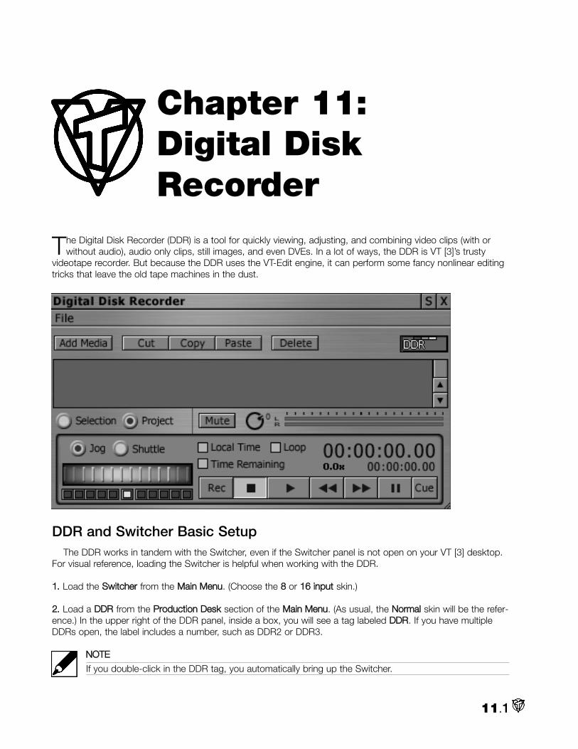
The Digital Disk Recorder (DDR) is a tool for quickly viewing, adjusting, and combining video clips (with orwithout audio), audio only clips, still images, and even DVEs. In a lot of ways, the DDR is VT [3]’s trusty
videotape recorder. But because the DDR uses the VT-Edit engine, it can perform some fancy nonlinear editingtricks that leave the old tape machines in the dust.
DDR and Switcher Basic SetupThe DDR works in tandem with the Switcher, even if the Switcher panel is not open on your VT [3] desktop.
For visual reference, loading the Switcher is helpful when working with the DDR.
11.. Load the SSwwiittcchheerr from the MMaaiinn MMeennuu. (Choose the 88 or 1166 iinnppuutt skin.)
22.. Load a DDDDRR from the PPrroodduuccttiioonn DDeesskk section of the MMaaiinn MMeennuu. (As usual, the NNoorrmmaall skin will be the refer-ence.) In the upper right of the DDR panel, inside a box, you will see a tag labeled DDDDRR. If you have multipleDDRs open, the label includes a number, such as DDR2 or DDR3.
NNOOTTEE
If you double-click in the DDR tag, you automatically bring up the Switcher.
11.1
Chapter 11: Digital DiskRecorder

33.. When you load a DDR, VT [3] automatically adds a new DDR input to the next available Switcher channel.(Depending on your last Switcher configuration, the DDR tag may already be there.) If you don’t have any avail-able channels on your Switcher skin, you can add the DDR to the Switcher, by dragging and dropping the DDRtag from its panel onto any channel on the Switcher. It will replace the input that was on the channel.
Or you can right-click on the DDR tag to bring up the CCoonntteexxtt MMeennuu where you can perform a number ofSwitcher actions directly. (These commands are not mutually exclusive. For example, you can select PPuutt oonnttooMMaaiinn IInn and then PPuutt oonnttoo PPrreevviieeww IInn, and the DDR will be placed on both.)
44.. To monitor the clips you are playing, open a VVTT--VViissiioonn and set it to PPGGMM (Program). Open a second VVTT--VViissiioonn and set it to PPrreevv (Preview).
Renaming the Tags
The numbered tags help you determine which DDR you are working with in the Switcher. The color-codeddashes on the tags correspond to the bus where the DDR input sits: red for Main, green for Preview, yellow forKey, and purple for the DSK (DownStream Key). (For more information on using the Switcher, see Chapter 9.)
You can rename the DDR completely from the DDR tag’s CCoonntteexxtt MMeennuu by selecting RReennaammee tthhiiss iinnppuutt. Thenew name also will be displayed in the Switcher.
NNOOTTEE
You also can rename tags by right-clicking on them in the Switcher.
If you prefer color-coding, you can tint your DDR panel. Its tag in the Switcher will reflect the new color. (Formore information on tinting panels, see Chapter 3.)
Adding ClipsYou can add content into the DDR in two ways:
11..aa.. In the upper left of the DDR panel, click on AAdddd MMeeddiiaa to launch the FFiillee RReeqquueesstteerr.. For this chapter, wewill use KSwim.avi and MareFoal.avi that came on the VT [3] Manual Content CD. Browse to the folder wherethey are located.
Or
11..bb.. After opening the DDR, open a FFiilleebbiinn separately from the Main Menu. Browse to your clip’s location anddrag and drop files from the Filebin to DDR’s PPllaayylliisstt area.
11.2

22.. To add multiple clips to the DDR, use SShhiifftt--cclliicckk to select multiple files in a consecutive range or CCttrrll--cclliicckk toselect multiple files non-consecutively.
33.. Click the OOppeenn button or drag and drop the items. All the files will load into the DDR Playlist in the order theywere selected.
44.. Add a transition to the Playlist. Click AAdddd MMeeddiiaa again, browse to the DVE folders, pick a favorite DVE, andOOppeenn it. Now on the Playlist, select the DVE and drag and drop it between KSwim and MareFoal.
PlaylistThe PPllaayylliisstt is the active work area where you assemble and adjust clips. Each clip stretches across the
Playlist with the clip name and timecode displayed between icons that represent the frames for the In and Outpoints.
NNOOTTEE
If you look closely, the clips in the Playlist are subtly shaded differently. Even if a clip has been color-coded,audio-only clips are a darker shade than still images or video-only clips. And audio/video clips sport atwo-tone bar – the lighter shade depicts the video portion, the darker the audio.
11.3

Adjusting Clips in the DDR
Trimming Clips
If you wish to play only a part of a clip, you can adjust its length by trimming it from either end. You markwhere you want the clip to start, (the In point), and where you want it to end, (the Out point).
11.. When you hover your mouse over the left edge of the clip, the cursor changes to crossbars with the word IINN.
22.. CClliicckk and ddrraagg the mouse to the right to move to the In point of your clip. (For visual reference, watch theplayback in a VT-Vision. If the clip has audio, you will hear it as you scrub.) Also, the timecode display on theclip’s icon changes from clip length to In point time.
33.. When you reach the frame you want as the In point, release the mouse button. The new clip length updates.
44.. Follow the same procedure to mark your Out point, except you must hover over the right edge of the clipand start by scrubbing to the left.
NNOOTTEE
If you need to adjust the In or Out point again, you must place the mouse cursor at the appropriate edgeof the clip; you do not place the cursor at the position of the In point or Out point.
55.. If you want to adjust the In or Out point without changing the length of the clip, hover over one of the clip’sedges and hold the SShhiifftt key. The cursor will change to SS//SS (slip and slide). Now when you click and drag, theIn and Out points move in tandem, leaving the clip’s length the same.
NNOOTTEE
Adjusting still images in the DDR is a little different since the clips do not have normal In and Out points.When you hover your mouse over either edge of the clip, the cursor changes to LEN for length. If youclick and drag left (from either end of the clip), you shorten the length of the clip. Drag right and the clipis lengthened. The timecode display gives real-time updates.
Trimming Audio Clips
You trim audio-only clips the same as video clips. If your video clips have interleaved audio, you can trim theIn and Out points for video and audio together or independently.
• To trim both audio and video, follow the procedure above for trimming a video clip.• To trim only audio, hold the CCttrrll key and follow the procedure for trimming a video clip. Notice that the
word AAuuddiioo appears on the clip.
Moving and Cloning Clips
You can easily change the order of items in the Playlist. Just select a clip and drag it up or down. When youfind the new position for your clip, release the mouse button to accept. The item will insert between other clipsin real-time.
To duplicate a clip in your Playlist, select it, CCooppyy and PPaassttee it. (Either use the buttons on the panel or thestandard keyboard shortcuts, Ctrl + c [Copy] and Ctrl + v [Paste]. Or right-click on the clip and select the func-tions from the Context Menu.)
A clone in the Playlist allows you to play different parts of a clip by setting different In and Out points for theclones.
11.4

NNOOTTEE
When you copy a clip, you clone only on the DDR. This action does not put extra copies of the clip onyour hard drive.
You always can choose multiple items, then copy the group. Shift-click to select a consecutive range ofitems or Ctrl-click to select several items non-contiguously.
Deleting Video Clips from the Playlist
To delete the entire Playlist, you can CCttrrll ++ aa to select all the clips and then use the DDeelleettee key or click on thepanel’s DDeelleettee button. Or you can right-click on a free area of the panel, and from that CCoonntteexxtt MMeennuu, select theCClleeaarr PPrroojjeecctt option. To delete a specific clip from the Playlist, select that clip and then choose DDeelleettee or CCuutt.
If you become overzealous in your housekeeping, you always can hit CCttrrll ++ zz to undo an operation.
NNOOTTEE
When you delete a clip from the DDR, you do not delete it from your hard drive. Files on your hard driveare not affected by actions in the DDR.
DDR and VT-Edit
If you need to make adjustments, like color correction, to a clip, you can drag it from the DDR Playlist intoand VT-Edit’s Timeline or Storyboard. In VT-Edit, open the clip’s Edit Properties panel and perform yourchanges. When you drag it back to the DDR, all of the new settings will be maintained. (See Chapter 8 for moreinformation about editing clips.)
Deck ControlsAt the bottom of the panel, the DDR offers standard deck controls: Rewind, Play, Fast Forward, Stop, and
Record, most of which are depicted by icons on buttons. When you click a button, it highlights.
11.5

Playing Clips
Click on the Play button to play your video clips. Depending on the Play mode you choose, the DDR plays allof the clips in your Playlist or selected clips.
NNOOTTEE
A vertical black line crawls along the bar of the clip giving you a visual reference about your position whenyou use any of the deck controls.
To force the DDR to jump to the beginning of a clip, double-click on the SSttoopp button.
NNOOTTEE
Remember to adjust the DDR Resource Usage, (in the Preferences panel under DDR), for the types ofclips you plan to play. Use Low resource usage for cuts-only, low-motion video, Medium resource usagefor files with few transitions, and High resource usage for projects with a lot of special effects. Using moreresources makes your processor work harder, and may slow other areas of VT [3].
Selection Mode
When you click in the circle labeled SSeelleeccttiioonn, (below the Playlist), you instruct the DDR to play only theselected clip or clips.
You choose a clip by clicking on it with your cursor. Shift-click toselect a range of clips, and Ctrl-click to select multiple clips independ-ently. Thus, you can select more than one video clip and the DDR playsonly those items that you’ve selected and ignores any other clips in thePlaylist.
The DDR also plays the clips in the order that you selected them. For example, let’s say you have ten clipsnamed One through Ten. If you wish to play Three, Seven, Two, and Nine, just Ctrl-click to choose them in thatorder.
To unselect all clips, click on an empty part of the work area. When no clips are selected, the DDR plays allthe clips – even when the SSeelleeccttiioonn mode is chosen.
Project Mode
If you activate the PPrroojjeecctt Mode circle, the DDR plays everything it sees in the Playlist, regardless of anyselections you make.
Loop Play Mode
If the LLoooopp box is checked, the selected clip will play repeatedly – continuously looping – until you click SSttoopp.
Even in PPrroojjeecctt Mode, only the current clip loops; the DDR does not loop through the entire project. You canloop a group of clips by choosing SSeelleeccttiioonn mode and choosing the clips that you want to repeat. The DDRruns through each selected clip until it reaches the end of the last clip and then it loops back to the first clip. Toloop the entire project, either select all of the clips or make sure no single clip is selected.
11.6

Timecode Display
NNOOTTEE
This manual often refers to timecode in the generic sense as the length of a clip (measured in hours, min-utes, seconds, and frames). Though, it also uses it in the specific sense as an absolute address for eachframe of video. (See below, Video 101: Timecode.) Depending on how you captured your clips, they willeither have timecode already attached or VT [3] will give it timecode.
You can choose how the DDR shows timecode in the two time displays above the Deck Controls.
11.. In this example, the DDDDRR has KKSSwwiimm..aavvii and MMaarreeFFooaall..aavvii loaded into it.
The first concept to explain is LLooccaall TTiimmee. If Local Time is nnoott checkmarked, when you play a clip, the topclock will begin playing at 00:00:00:00, no matter where the clip’s timecode starts.
22.. Select KSwim.avi and play it. Now, a clip like KSwim has timecode that starts at 00:00:00:00. But change itsIn Point to 00:00:02:00, and play it again. It still starts at 00:00:00:00.
33.. Now checkmark LLooccaall TTiimmee and play KSwim again. This time the display begins at the clip’s In Point time-code.
If a clip was captured with timecode, such as MareFoal.avi, then if Local Time is on, the display will play thattimecode. Turn off Local Time and it begins at 00:00:00:00.
Now, the next factor in determining the timecode readout is TTiimmee RReemmaaiinniinngg. If it is checkmarked the clockdisplays remaining time and not elapsed time. The clock begins at the total duration of the selected clips orproject and counts backward.
NNOOTTEE
You should turn Local Time off if you are using Time Remaining.
4. Turn off Local Time, choose SSeelleeccttiioonn, and pick KKSSwwiimm. The top clock should say 00:00:00:00. Now,checkmark Time Remaining and the display will change to the length of the clip. Hit Play and the clock will windbackward to 00:00:00:00.
11.7

HHIINNTT
The Time Remaining mode is a great feature when you use the DDR with the Switcher – you can see thetime left in a particular clip and know how long before you need to switch to your next source.
The bottom clock displays the duration of the project, (if PPrroojjeecctt is marked), or the duration of the clipsselected if SSeelleeccttiioonn is picked.
11.8
VIDEO 101:Timecode
For timing, synchronization and editing purposes, video professionals needed a specific method of measur-ing the duration of video on tape. The Society of Motion Picture and Television Engineers (SMPTE) agreedon standards called video timecode which is measured by HH:MM:SS:FF, (Hours, Minutes, Seconds, andFrames). The range is from 00:00:00:00 to 23:59:59:29.
Professional cameras and video decks can record timecode as they record the video signal. Therefore, time-code also can act as an absolute address for each frame of a video project, allowing for frame accurateediting and batch capturing.
In the U.S., timecode is dished out in two popular flavors. Non-drop frame assigns a progressive numberto every video frame (0-29). However, because NTSC video actually runs at 29.97 frames per second,not 30 frames, (don’t ask), the timecode system must compensate for 3.6 seconds each hour.
Drop-frame timecode was created by video engineers to adjust for this loss. Every minute, the timecodecounter skips counting (drops) two frames, except when the number of the minute ends in zero (ie., 10,20, etc.). No frames are lost, the counter just skips the numbers for the two frames.
The 50 fps PAL system is exact and does not require drop-frame.
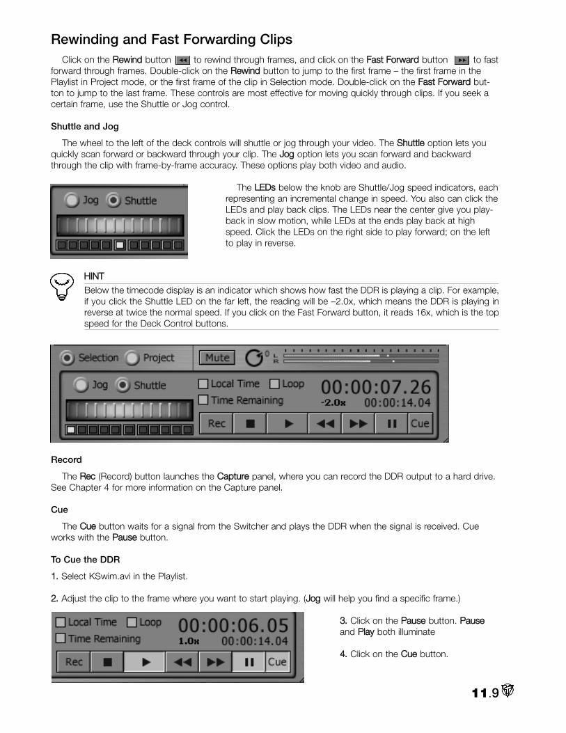
Rewinding and Fast Forwarding ClipsClick on the RReewwiinndd button to rewind through frames, and click on the FFaasstt FFoorrwwaarrdd button to fast
forward through frames. Double-click on the RReewwiinndd button to jump to the first frame – the first frame in thePlaylist in Project mode, or the first frame of the clip in Selection mode. Double-click on the FFaasstt FFoorrwwaarrdd but-ton to jump to the last frame. These controls are most effective for moving quickly through clips. If you seek acertain frame, use the Shuttle or Jog control.
Shuttle and Jog
The wheel to the left of the deck controls will shuttle or jog through your video. The SShhuuttttllee option lets youquickly scan forward or backward through your clip. The JJoogg option lets you scan forward and backwardthrough the clip with frame-by-frame accuracy. These options play both video and audio.
The LLEEDDss below the knob are Shuttle/Jog speed indicators, eachrepresenting an incremental change in speed. You also can click theLEDs and play back clips. The LEDs near the center give you play-back in slow motion, while LEDs at the ends play back at highspeed. Click the LEDs on the right side to play forward; on the leftto play in reverse.
HHIINNTT
Below the timecode display is an indicator which shows how fast the DDR is playing a clip. For example,if you click the Shuttle LED on the far left, the reading will be –2.0x, which means the DDR is playing inreverse at twice the normal speed. If you click on the Fast Forward button, it reads 16x, which is the topspeed for the Deck Control buttons.
Record
The RReecc (Record) button launches the CCaappttuurree panel, where you can record the DDR output to a hard drive.See Chapter 4 for more information on the Capture panel.
Cue
The CCuuee button waits for a signal from the Switcher and plays the DDR when the signal is received. Cueworks with the PPaauussee button.
To Cue the DDR
11.. Select KSwim.avi in the Playlist.
22.. Adjust the clip to the frame where you want to start playing. (JJoogg will help you find a specific frame.)
33.. Click on the PPaauussee button. PPaauusseeand PPllaayy both illuminate
44.. Click on the CCuuee button.
11.9

55.. Place the DDDDRR channel on the PPrreevviieeww bus of the SSwwiittcchheerr.
66.. Open a second DDR (if you haven’t already). Right-click on the DDDDRR ttaagg and choose, PPuutt oonnttoo MMaaiinn IInn. AAddddMMeeddiiaa onto the PPllaayylliisstt and select a clip or simply drag and drop MareFoal.avi from the first DDR. You shouldsee it on the VVTT--VViissiioonn set to PPGGMM.
77.. Now, on the SSwwiittcchheerr, click AAuuttoo to transition between your MMaaiinn source and the PPrreevviieeww source with thecued KSwim. As soon as the switch occurs, the KSwim begins playing automatically and you will see it on theVVTT--VViissiioonn set to PPGGMM.
88.. Switch between MMaaiinn and PPrreevviieeww again. When the DDR returns to the PPrreevviieeww bus, the KSwim pauses andawaits a further prompt from the Switcher.
NNOOTTEE
If the DDR is in Selection mode, this behavior carries into the Switcher. So you can choose specific clipsthat you want to play, Cue the DDR, and when the Switcher makes the DDR live, you play only yourselected clips.
DDR and AudioWhen you add an audio-only clip in the DDR, it starts playing when the video (or still image) clip directly
above it begins, and the audio clip continues playing until it ends.
For example, if you load a five second video clip in the DDR and then add a ten second audio clip and thenanother seven second video clip; the audio will start when the first video begins and continue to play for fiveseconds into the second video. This behavior is true even if the video clip above or below has audio, whichmeans you’ll hear overlapping audio from the two clips. If you load two separate audio clips next to each other,they will not play at the same time. The first will play all the way through and then the second will begin.
To Adjust the Volume of a Single Clip in the DDR
11.. Drag and drop the clip into VVTT--EEddiitt.
22.. Open the clip’s EEddiitt PPrrooppeerrttiieess panel, select the audio stream and change the audio settings.
33.. When you drag the clip back to the DDDDRR, all of your changes are maintained.
To Control the Overall Volume of the DDR
11.. Rotate the aauuddiioo kknnoobb next to the MMuuttee button on the panel.
22.. Start playing the project and rotate the knob coun-terclockwise to lower the volume and clockwise toraise it.
33.. To make sure that you are not distorting the sound,refer to the VVUU mmeetteerrss next to knob.
For greater control, you can patch the DDDDRR into the AAuuddiioo MMiixxeerr where your changes will affect every clip inthe DDR as a whole. You cannot drag specific clips into the Audio Mixer. (For more information about the AudioMixer, see Chapter 9.)
Of course, if you just wish to mute the DDR audio playback, click on the MMuuttee button.
11.10

Context MenuImporting and Exporting VT-Edit Projects
DDRs can import and play back VT-Edit projects. Instead of Adding Media, you right-click in the DDR panelto bring up the CCoonntteexxtt MMeennuu. Under Projects, select IImmppoorrtt VVTT--EEddiitt PPrroojjeecctt……. Browse in the File Requester toyour project and OOppeenn it.
If you make changes to the project, select EExxppoorrtt VVTT--EEddiittPPrroojjeecctt…… and save it. You also can use the Export feature to save,as a VT-Edit project, a Playlist that you created in a DDR.
Saving DDR Configurations
You can save different instances of the DDR with differentPlaylists and load those instances at another time. Usually configu-rations are saved from the panel’s Context Menu. The DDR is dif-ferent.
11.. At the top of the VT [3] desktop screen is a strip of rectangulartags for the panels loaded in this desktop. If you have more thanone DDR loaded, you’ll notice that these tags are not numbered.To make sure which DDR tag you are working with, click on thetag once and the DDR panel will minimize. Click it again and thepanel will reappear.
22.. Now, right-click on the appropriate DDR tag in the strip.
11.11

From the CCoonntteexxtt MMeennuu, select SSaavvee ……, and in the FFiillee RReeqquueesstteerr, browse to where you are saving yourConfiguration files. Give it a meaningful name so that you can recognize it easily later.
33.. To load a previously saved DDR configuration, you need to open a DDR panel first and then right-click on itsttaagg in the strip. When you load a configuration, whatever was in the panel will be replaced.
Closing the DDR
To close the DDR panel, click on the XX in the upper left corner. Like other panels in VT [3], the DDR remem-bers your most recent settings when you close the panel, including any clips that you loaded into the Playlist.They will reappear when you open the DDR again, unless you delete them before you close the panel.
11.12

In VT [3]’s Character Generator, (CG), you can create text and combine it with graphics to produce elementslike titles, lower thirds, bugs, credits, scrolls and crawls.
When you design graphics in the Character Generator, you work on pages. If you create one graphic for atitle, another for a station ID, and another of scrolling credits, each would be a different page. Completed pagesare saved as image files and can be loaded into VT-Edit or the Switcher. Pages also can be played from the CGinterface (or the CG Player), directly into the Switcher.
HHIINNTT
If you are not artistically inclined, NewTek has packaged 100 colorful and creative templates (made byTim Johnson). Beyond being great inspiration, you can load them into your projects as a page and alterthem to fit your needs. (See the section at the end of the chapter on how to use Templates.)
12.1
Chapter 12: CharacterGenerator

Basic Character Generator Setup 11.. Load the CChhaarraacctteerr GGeenneerraattoorr from the PPrroodduuccttiioonn DDeesskk section of the MMaaiinn MMeennuu.
22.. The Character Generator panel is a fairly large interface, but you should open a VVTT--VViissiioonn monitor and set itto PPGGMM (Program Out), even if it is partially covered by the CG panel in a single monitor VT [3] setup
33.. If your Character Generator work will be seen outside of the computer world, (broadcast, videotape, DVDs,etc.), then it’s critical that you view your CG output on an NNTTSSCC mmoonniittoorr. Text can reveal the worst flaws in theNTSC system like dot crawl and blooming. CG pages that look great on computer displays like VT-Vision canlook like amateurish garbage on an NTSC monitor.
44.. Before you begin generating characters, click on the VViieeww tab and checkmark SSaaffee AArreeaass (see below).
FileAt the top left of your panel is the FFiillee button. The pull down menu
provides options to open and add files; and save pages, images, orprojects. CG pages and projects are saved as *.cg files
NNeeww – Clears the current project and opens a new blank one.
OOppeenn – Clears the current project and loads another one. Or you canimport a .txt document into your current project.
AAdddd FFiilleess – Adds a saved CG page or project to your current project.
SSaavvee PPrroojjeecctt – Saves all pages in the current project. In the FileRequester, make sure to pick **..ccgg as the extension.
SSaavvee CCuurrrreenntt PPaaggee – You save only the active page in the CG. Again, pick **..ccgg as the extension.
SSaavvee IImmaaggee FFiillee – The current page is rendered and is saved as an image file. All the elements on the page,(except for those marked Do Not Render), become one image and can no longer be edited separately whenyou load the image file.
NNOOTTEE
Still Pages can be saved in a variety of formats. (Portable Network Graphics, or png, is a favorite of someof the development staff. Others prefer Targa, .tga.) Motion Pages should be saved as an rtv.
RReecceenntt PPrroojjeeccttss – Lists your most recent CG projects for quick access.
12.2
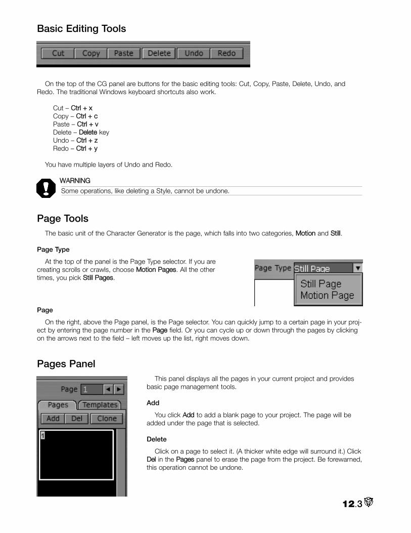
Basic Editing Tools
On the top of the CG panel are buttons for the basic editing tools: Cut, Copy, Paste, Delete, Undo, andRedo. The traditional Windows keyboard shortcuts also work.
Cut – CCttrrll ++ xxCopy – CCttrrll ++ ccPaste – CCttrrll ++ vvDelete – DDeelleettee keyUndo – CCttrrll ++ zzRedo – CCttrrll ++ yy
You have multiple layers of Undo and Redo.
WWAARRNNIINNGG
Some operations, like deleting a Style, cannot be undone.
Page ToolsThe basic unit of the Character Generator is the page, which falls into two categories, MMoottiioonn and SSttiillll.
Page Type
At the top of the panel is the Page Type selector. If you arecreating scrolls or crawls, choose MMoottiioonn PPaaggeess. All the othertimes, you pick SSttiillll PPaaggeess.
Page
On the right, above the Page panel, is the Page selector. You can quickly jump to a certain page in your proj-ect by entering the page number in the PPaaggee field. Or you can cycle up or down through the pages by clickingon the arrows next to the field – left moves up the list, right moves down.
Pages Panel This panel displays all the pages in your current project and provides
basic page management tools.
Add
You click AAdddd to add a blank page to your project. The page will beadded under the page that is selected.
Delete
Click on a page to select it. (A thicker white edge will surround it.) ClickDDeell in the PPaaggeess panel to erase the page from the project. Be forewarned,this operation cannot be undone.
12.3

Clone
CClloonnee copies the page that is selected and pastes the copy below it – all with one click of the button.
Templates Panel
The CG comes preloaded with 100 templates from Tim Johnson. You canuse the scroll bar to scan down the list of templates. Click on a template tosee its thumbnail displayed above the list.
Insert
When you find a template that you want to put in your project, select it andhit IInnsseerrtt. Templates cannot be edited, but once you insert it into your project,it becomes a page that you can alter. Make sure to save the page or project.
Add
If you make a page design that you want to use later, one of your choicesis to select in the PPaaggeess panel and then go to the TTeemmppllaatteess panel and hitAAdddd.
Delete
If you find a Template that has to go, select it and hit DDeelleettee. Be fore-warned, it’s gone. Undo won’t bring it back.
Now put the templates away. They will be discussed later.
CHARACTER GENERATOR INTERFACETo access many of the tools in the CG panel, you click on the appropriate tabs. For example to change text
attributes, you click on the TTeexxtt tab at the bottom of the panel.
View Tab
The VViieeww panel is the first place to go when you start a CG session. Here is where you set the basic look ofyour Character Generator WWoorrkk AArreeaa.
Safe Area
As mentioned above, you should checkmark the SSaaffee AArreeaabox, which will overlay a simple white cross hair and two boxeson the Character Generator work area. (The outer box is barelyvisible.) The SSaaffee AArreeaa gives you a guideline for placing action ortext so that it appears properly on a television monitor.
12.4

It’s a hard, cruel fact of video life that not all televisions display the same frame. For example, some TVs willoffset the image to the left or right, occasionally quite far off center. Because of this variation from set to set,video professionals must rely on the dual-bordered Safe Area.
The inner box represents the safe title area where you should place text. Actually, if you have essential graph-ic elements like a pie chart, they also should be placed in the inner box. The outer box indicates the edge of theactive video, which includes overscan. Halfway between the safe title and active video is the safe action area.The region outside the active video area will not appear on output.
To ensure that your text and graphics are visible, heed the safe area. And that’s why you should checkmarkthe SSaaffee AArreeaa box. If it bugs you, then toggle it on at least once to check the layout of your text.
Grid
To assist in laying out and aligning text and graphics, you can customize a grid that overlays your CG WorkArea. The Grid is just for reference and does not show if you save the CG page or output it directly to theSwitcher.
11.. Checkmark the GGrriidd box and the grid appears on the work area.
22.. Use the sslliiddeerrss next to the numeric entry field to change the values. (You also can type in new numbers.) Thebox on the left spaces the vertical lines horizontally. The box on the right spaces the horizontal lines vertically.The units are pixels. So if you want a grid of 10 by 10 lines, you would enter 72 (pixels) in the left box and 48 inthe right, (for NTSC 720 x 480 output).
33.. If you checkmark SSnnaapp, the edgesof your text or graphics box will snapto the intersection of grid lines whenyou move the box close to the lines.
12.5

Guides
GGuuiiddeess are another alignment assistant. Like the Grid, Guides do not appear if you save the CG page or out-put it directly to the Switcher.
11.. To activate Guides, first go to DDiissppllaayy and checkmark RRuulleerrss, and then checkmark GGuuiiddeess.
22.. Now, when you move your cursorover the two Rulers (on the top or leftedge of the Work Area), a little black linemarks the spot on the Ruler.
33.. Click on the RRuulleerr on the lleefftt edgeand the cursor turns into a double arrowicon. DDrraagg the mouse into the WWoorrkk AArreeaaand you will see a vveerrttiiccaall bblluuee GGuuiiddeeline. When you have moved it to yourpreferred location, rreelleeaassee the mouse.
If you click on the RRuulleerr at the ttoopp and ddrraagg the mouse down, you create a hhoorriizzoonnttaall gguuiiddee line.
Snap works the same with Guides as it does with the Grid.
44.. If you click on the CClleeaarr GGuuiiddeess button, you will clear all the Guides.
55.. Try this. Pull out three horizontal Guides. Now, go back up to the top Ruler and click on it (a simple click andrelease). The last Guide that you created is deleted. Click again and the second to last vanishes. You get theidea.
66.. Of course, if you just want to hhiiddee the Guides, uncheck the GGuuiiddeess box. When you checkmark it again, theGuides reappear.
Wireframe
The WWiirreeffrraammee feature (when checkmarked)simplifies the Layout by displaying text andgraphic elements as wireframes. Also if youare creating very large scroll pages, Wireframeprovides the greatest screen refresh mode. Ifyou have images on your Work Area, they willdisappear in Wireframe mode. Once again,this look will not be reproduced as output.
Rulers
When you checkmark RRuulleerrss, the Work Area display shifts to allowfor two rulers – one on the top and the other on the left. The meas-urements are in pixels.
Output Options In the Output Options you can feed your CG out to the Switcher and routes a VVTT--VViissiioonn signal back to an
input into the Character Generator.
VT-Vision
When you click VVTT--VViissiioonn, the Program Out signal from the Switcher is fed into the CG’s Work Area background,allowing you to directly align your type or graphics to the Program Out. There are a couple of tricks to this method.
12.6

11.. For this example, open a DDDDRR and load a clip into it. Click on the DDDDRR ttaagg and from the CCoonntteexxtt MMeennuu,select PPuutt oonnttoo MMaaiinn IInn.
22.. Make sure your VVTT--VViissiioonn is set to PPGGMM (Program Out). You should see the DDR clip in VVTT--VViissiioonn.
33.. Now, in the Character Generator, checkmark VVTT--VViissiioonn. You should now see the clip as background in theCG Work Area.
NNOOTTEE
If you have Rulers checked, it will disappear when VT-Vision is on. Also, if you add a full-sized back-ground image to your page, it will cover this Program Out background.
44.. Type or draw in the Work Area. You should see it over the Program Out background.
55.. If you don’t see it, open the SSwwiittcchheerrand in the DDoowwnnSSttrreeaamm KKeeyy (DSK) win-dow, make sure that CChhaarraacctteerrGGeenneerraattoorr is selected. If it is and you stillcan’t see your typing, click FFaaddee DDSSKK.
The DDSSKK FFaaddeerr meter should now say 110000%% and you should see your typing over the Program Out back-ground in the CG Work Area. (For more information on the DSK, see Chapter 7.)
66.. Now, return to the CChhaarraacctteerr GGeenneerraattoorr. In the VViieeww panel, next to the VVTT--VViissiioonn option, checkmark OOuuttppuuttttoo SSwwiittcchheerr, which will uncheck VT-Vision.
In the Work Area, the Program Outbackground disappears though your typ-ing remains.
If you look at your VT-Vision monitor,the typing still will be over the DDR clipbecause you have the CharacterGenerator in the DSK faded in. If youFFaaddee DDSSKK again, the CharacterGenerator output will fade off theProgram Out.
Out to Switcher
When you checkmark OOuutt ttoo SSwwiittcchheerr, the current CG page is sent to the SSwwiittcchheerr. The DDoowwnnSSttrreeaamm KKeeyy isautomatically loaded with the Character Generator and faded in. The page is keyed over the Program Out ofthe Switcher and you will see the result on your VT-Vision monitor set to PGM.
12.7

ENTERING TEXTYou control the text that you type in the Work Area from two complementary locations: the TTeexxtt TToooollss tab on
the upper left and the TTeexxtt attributes tab at the bottom. The two areas are linked. If you click on the TTeexxtt tab onthe left, the TTeexxtt tab on the button will respond and open, and vice-versa.
Text ToolsT (Text)
Click on the TT box to activate the text function. Before you entertext, this box has to be highlighted.
11.. For this example, start with a blank page. If you don’t have one, goto the right of the Character Generator panel, click on the PPaaggeess taband click AAdddd.
22.. Go to the bottom of the CG panel and open the SSttyylleess tab. Click topick SSttyyllee ##11 – a simple white Arial font.
33.. Now, click in the WWoorrkk AArreeaa and an II--bbeeaamm icon startsblinking. This is your Work Area cursor. When you type, theI-beam is the insert point for the text. You can move the I-beam anywhere on the Work Area by clicking on it withyour mouse and dragging it around or just clicking yourmouse on another spot in the Work Area.
44.. Turn on your SSaaffee AArreeaa display and click the cursor near the left edge of the inside box.
55.. Type in, WWeellll bbeegguunn.
HHIINNTT
Use the End and Home keys onyour keyboard to navigate to thebeginning and end of text lines. Ifyou mistyped, you can use theBackspace key to erase or thekeyboard arrow keys to go back orforth on the line or up and downbetween lines.
Selecting Letters or Words
66.. You can click your cursor anywhere on the line and drag your mouse to select letters or whole words. Theywill be displayed in the text’s reverse color.
HHIINNTT
This selection technique can be alittle tricky. You need to click nearthe center (from top to bottom) ofthe line. If you get too low or high,you’ll just move the cursor around.
12.8

Arrow (Selection)
Clicking on the AArrrrooww box activates the SSeelleeccttiioonn tool (and switches off the TTeexxtt tool). Unlike the previousselection method, this one is a more global technique because it selects the whole line and not just parts of it.
77.. If you have just typed something in, clicking the AArrrrooww will create a box around what you typed. If it didn’t,select the line by clicking anywhere on it.
88.. When you roll your mouse overthe box, the cursor changes.
When it becomes a two-headedarrow, that means you can click tograb an edge of the box and drag itin or out to resize the text. At thebottom of the CG panel, click theTTeexxtt tab to open the Text
Properties panel. UUnnddeerr FFoonntt && OOrriieennttaattiioonn are WWiiddtthh and HHeeiigghhtt boxes. Go back to the Work Area and dragthe edges of the box until the letters are about 75 x 75. (Don’t worry if you can’t get it exact.)
When the cursor sprouts four arrowheads, that means you can click and grab the whole box to move itaround the Work Area.
Object Color
You can choose the color of your type by clicking in the box to the right of OObbjjeecctt CCoolloorr, which brings up theColor Picker panel. Or you can right-click in the box to activate the Eyedropper tool. (For more information onusing the Color Picker and Eyedropper, see Chapter 13.)
WWAARRNNIINNGG
If you click and drag the color box onto the CG panel, it will tint the panel that color, which is a handyoption if that is what you want to do. But if you inadvertently drag black on to the panel, you’ll tint it black,which you don’t want. To bring the panel back to normal, right-click on an open area of the panel andselect Clear Current Shading.
99.. Before you pick a color, make sure that your text is selected.
From the CCoolloorr PPiicckkeerr, choose a nice bright yellow, which instantly tints your text on the Work Area.
12.9

Edge
The two boxes directly below the EEddggee button are where you choose the colors for the inside andoutside edges of the Edge. Inside is the box on the left, outside is on the right. (The third bigger boxis for the Shadow.) Again, you either click in the box to bring up the Color Picker panel or right-click in
the box to activate the Eyedropper tool.
HHIINNTT
You have more Edge options in the Text panel at the bottom of the CG panel. Usually, you will want toset your Edges there along with all the other Edge attributes.
1100.. Click on the left box and pick a dark blue for the inside edge. This time you won’t see it appear on theWork Area.
1111.. Click on the other Edge box and pick a rosy red.
1122.. Now, click on the EEddggee button. The selection box turns into a Edge adjustment box. When you roll your mouseover the edges of this box around your text, the cursor turns into a diamond with a directional arrow attached.
Click and drag the mouse away from the text. The edge will expand.
1133.. In the Text Properties panel, notice under EEddggee is a SSiizzee entry. As you play with the Edge adjustment box,you will see the numbers change. Around 1100 seems good for now.
Shadow
The box directly below the SShhaaddooww button is where you select the colors for the Shadow. Like Edge,you have more Shadow options in the TTeexxtt panel at the bottom of the CG panel.
1144.. Click in the Shadow box and choose a light green shadow. Make it semi-transparent by changing the AAllpphhaavalue to 150.
HHIINNTT
You’ll notice the transparent shadow better when you put video or an image in the background.
1155.. Click on the SShhaaddooww button to change the selection box to a Shadow adjustment box. This time when youroll your mouse over the box, the cursor turns into a four-headed arrow or a two-headed lightning bolt .
Look at the SShhaaddooww area of the TTeexxtt PPrrooppeerrttiieess panel
If you grab one of the edges of the box and drag the mouse, you move the location of the Shadow in refer-ence to the text, (expressed in X and Y axes values). You also can just click in the middle of the box and drag it.
If you grab a corner, (the lightning bolt), and drag the mouse, you adjust the tilt or Italics of the Shadow bymoving the X independent of the Y or vice versa.
Play around until you find a shadow that you like.
12.10

Justification ButtonsBelow the Edge and Shadow boxes are four buttons for aligning text. The first
three are justification buttons commonly found in word processing programs.
NNOOTTEE
Remember, you need to select your text before you can justify it.
Left Justify
This button will align your text and move the beginning of the line(s) just inside the left edge of the TextSafe Area.
Center
This button will align the center of the line(s) with the center of the Safe Area.
Right Justify
This button will align your text and move the end of the line(s) just inside the right edge of the Text SafeArea.
Lower Third
This button moves your text so that the bottom line is situated at the top of the lower third of the WorkArea.
NNOOTTEE
Lower Third is a video tradition in which names and titles – placed on the lower third of the screen – werekeyed over on-air talent. Since the shot often was of the announcer’s head and shoulders, the titles didnot cover the head.
1166.. To add a second line to the quote, hit the TT button and then simply click in the Work Area below the firstline. Type IIss HHaallff DDoonnee.
1177.. Click the AArrrrooww key and select the top line. Notice a box is only drawn around that line. The second line is aseparate object. To select it with the first, hold down the CCttrrll key and click on the line.
Now, boxes should be around both lines.
HHIINNTT
When you have the Arrow key selected,you also can grab multiple lines or objectsby clicking your mouse in an empty areaof the display and dragging out a bound-ing box around the items.
1188.. Click on the justification keys to see howthey work.
1199.. You also can click in either box and dragthem together around the Work Area.
12.11

Group and UnGroup
Even though each line is a separate object, you can select multiple lines and GGrroouupp themtogether to act as one object. The UUnnGGrroouupp button undoes the union.
2200.. Deselect the WWeellll BBeegguunn line by hitting CCttrrll ++ cclliicckk. Now, with IIss HHaallff DDoonnee selected, offset it to the right.
2211.. Reselect the top line with a CCttrrll ++ cclliicckk and hit the GGrroouupp button. One big box envelops both lines.
2222.. Hit the CCeenntteerr justificationbutton and the center of the boxis aligned with the center of theWork Area.
2233.. Hit UUnnGGrroouupp and the linesbecome separate entities again.
TEXT PROPERTIES PANEL
When you click on the Text tab at the bottom of the CG panel, you bring up the Text Properties panel, whereyou can perform more exacting adjustments to your text.
12.12

Font & Orientation
Font Type
The first box in this section is not labeled, but it is where you choose the Font. VT [3] looks in your WindowsFont folder and tries to display all the fonts in the folder in their respective font styles. If you have some funkyfonts, the menu might have some difficulty reproducing the font.
HHIINNTT
If you are one of those people who have 3000 fonts in their folder, you can imagine that VT [3] might geta little cranky trying to display all of them. Try trimming down the fonts in the Windows Font folder andstoring the ones that you rarely use in another spot.
Changing a Font Style
If you want to change the font on something you have already typed, you must select it first and then pick anew font from the menu.
2244.. Click on the AArrrrooww button and then select WWeellll BBeegguunn. From the FFoonntt MMeennuu, choose TTiimmeess NNeeww RRoommaann.
2255.. Now, deselect WWeellll BBeegguunn by clicking in a blank spot of the Work Area. Hit CCttrrll ++ aa to Select All, (in thiscase, both lines), and choose another font like BBooookkmmaann OOlldd SSttyyllee.
Bold
2266.. To Bold the lines, click on the BB button to the right of the Font Menu.
Italics
2277.. For Italics, click the II button. Notice that the shadow slants with the text.
12.13

To adjust the amount of slant, hold the SShhiifftt key down and move your cursor over the top or bottom of theselection box. When you see the cursor change to a lightning bolt with two arrowheads, click and drag to slantthe text more or less.
To straighten up the text, click off the II button.
Width and Height
Width and Height are measured in points. You can either type in values or use the slider next to the entrybox.
NNOOTTEE
Points are a common measurement for text used by printers and graphic artists. Points do not equal pix-els. So a font that is 75 points high is not necessarily 75 pixels high. To make matters more confusing, a75 point A in Times New Roman is not the same height as a 75 point A in Courier New.
Lock Aspect Ratio
Checkmark this option when you want the Width and Height to be the same. This function does not workwhen you are adjusting size by stretching and contracting the selection boxes.
2288.. Click on LLoocckk AAssppeecctt RRaattiioo. Select WWeellll BBeegguunn and drag the bottom of the box to make it taller. Now, thevalue in the HHeeiigghhtt is larger than the WWiiddtthh.
2299.. Move the WWiiddtthh slider and the HHeeiigghhtt value will jump to the WWiiddtthh’s. If you had adjusted the Height’s first,the Width would have fallen in line with the Height.
NNOOTTEE
Lock Aspect Ratio is not in effect when you type in values.
Rotate
To rotate your text, you can enter values in the RRoottaattee box, use the slider, or manipulate it by hand. If youhave only one line selected, the axis of the rotation is the center point of the box.
3300.. Select the line, IIss HHaallff DDoonnee. Hold the SShhiifftt key down and CCrroosssshhaaiirrss appear in the middle of the box. Thisis the axis point. With the Shift key still down, move your cursor outside the box and it will turn into a curvedtwo-headed arrow, which indicates that you can click and twist the line of text. Twist it and then hit the UUnnddookey above the Work Area to bring it back to 0. (CCttrrll ++ zz is the keyboard shortcut for Undo.)
12.14

3311.. Select WWeellll BBeegguunn. Now, both lines are chosen. Use the RRoottaattee slider to twist them. Notice that they rotatearound their individual center points.
3322.. Hit GGrroouupp and RRoottaattee. The two lines turn around a common center point. UUnnddoo and UUnnGGrroouupp them.
Tracking
When you adjust TTrraacckkiinngg, you are altering the space between groups of letters. As usual, you need toselect the text that you want to track. The larger the number, the more space is inserted between the letters,which makes the page look more open. You can enter negative numbers, which will reduce the space beyondthe normal default spacing, making the line look denser.
33. Hit Ctrl + a to select both lines and slide Tracking to 8. When letters have big edges, sometimes you wantto give them a little more space to make the words more legible.
Kerning
Kerning adjusts the space between pairs of letters. To kern two letters, click the TT button and then with yourmouse select the first letter of the pair.
Now while holding down the AAlltt key use the rriigghhtt aarrrroowwkey on the keyboard to add space between the pair of let-ters. Use the lleefftt aarrrrooww key to reduce the space.
How much to kern is a matter of personal aesthetics.
Leading
The space between lines in called LLeeaaddiinngg; and like Width and Height, it is measured in points. Obviously,the Leading setting does not come into effect until you have typed at least two lines with a carriage returnbetween them. You cannot adjust leading after you have typed. You set the Leading first and then type.
3344.. AAdddd a page. Go back to SSttyyllee and pick ##11 again. Change WWiiddtthh and HHeeiigghhttto 3355 and make LLeeaaddiinngg 3355. Leave TTrraacckkiinngg at 00. On the new page, type:
Make visible what, without you, Might perhaps never have been seen.
Robert Bresson
Direction of Typing
In the box below LLeeaaddiinngg, you can choose which direction the letters willdisplay when you type: LLeefftt ttoo RRiigghhtt, RRiigghhtt ttoo LLeefftt, UUpp ttoo DDoowwnn. The lasttwo choices are usually reserved for specific languages.
12.15

Lock Item Position
When you checkmark this feature, the item that isselected will remain stationary, which is important whenworking with Motion Pages (See 12.39.)
Do Not Render
Occasionally, you may want an item for reference, but you don’t want to see it on the final page. Select itand checkmark DDoo NNoott RReennddeerr. It will not be reproduced when you Output to Switcher or Save the page asan image.
EdgeType
From the pull down menu, you can choose from three edge types:RRoouunndd, SSqquuaarree, and BBeevveell. As usual, make sure that you have selectedyour text before you change any Edge attributes.
Color
Next to the TTyyppee box are two boxes for choosing the colors for the inside (left box) and outside (right box)edges of the Edge. These two work exactly like the two EEddggee color boxes in the TTeexxtt TToooollss panel in the upperleft of the CG panel. Any changes made here will be reflected in the other panel.
Again, you either click in the box to bring up the Color Picker panel or right-click in the box to activate theEyedropper tool.
Size
Edge SSiizzee is measured in pixels, so a setting of 25 means that the inner and outer edge combined is 25 pix-els on each side of the text.
ShadowType
To create a shadow, you must choose one of the three types: Cast,Soft, and Drop, which are easier to show than explain.
HHIINNTT
Since Edges also cast a shadow, the clearest way to see the dif-ferences is to either turn Edges off or make it very small, like 2.Also, offset the Shadow some distance from the text by adjustingthe X and Y values (see below).
12.16

Cast Shadow
Cast applies a hard shadow behind your text, which is a duplicateof the text offset from the original.
11.. AAdddd a new page and select Style #1. Type an XX, size the FFoonntt to200 x 200.
22.. In the TTyyppee window, select CCaasstt.
33.. To the right of that window, click in the Shadow color box and picka light blue shadow from the Color Picker that pops up.
44.. In the Shadow’s X box, enter 75 and YY = 50. These will give you adistinct separation between the text and the shadow.
Soft Shadow
A SSoofftt shadow is similar to Cast except the shadow color is blend-ed with the background and the edges are blurred.
55.. From the TTyyppee pull down menu, change from CCaasstt to SSoofftt.
Softness
SSooffttnneessss lets you apply a blur amount to a Soft shadow for a soft-er edge. Use higher values to get softer shadows with more blur.
66.. Set the SSooffttnneessss to 20.
Drop Shadow
DDrroopp creates a hard shadow that originates from the base of the original text.
77.. From the TTyyppee pull down menu, change from SSoofftt to DDrroopp.
Often with shadows, you want to add some transparency to the shadow’s color.
88.. Click on the Shadow’s color box and in the Color Pickerchange the AA (Alpha) setting to 125.
12.17

Italic
Italic gives you independent italics for the shadow, whichis separate from the object’s italics. You adjust your shadowitalics by entering a number (measured in pixels) in the Italicbox. This technique offsets the top of the text. A positivevalue moves the top to the left; negative values move it tothe right.
99.. In the Italic box enter ––3300. The shadow will lean to theright.
HHIINNTT
As described earlier, you can tilt the shadow by drag-ging either the top or bottom of the Shadow selectionbox in the Work Area.
X and Y Offsets
You enter values (measured in pixels) in the X and Y boxes to separate the shadow from the text. You caneither type in values or use the slider next to the entry boxes.
The XX position moves the shadow horizontally. A negative number in X will offset the shadow to the left of thetext; positive to the right.
The YY Position moves the shadow vertically. A negative number on the Y will offset the shadow above thetext; a positive one below.
NNOOTTEE
Any and all changes you make to text, edges, and shadows will remain current even if you change pagesor close the Character Generator. That means, if you picked a gold and green edge for the text of yourMardi Gras graphics, that edge will be applied to everything you type afterwards. (Actually, it will apply toobjects that you draw also.) If you change it to green and red, then those will be the current edge colors.
HHIINNTT
If you create a combination of attributes that you want to use again later, you can save them as a Style,(see below). Also, if you type a line with certain attributes and then type another line and change the attrib-utes, you can go back to the first style by selecting the first line. Then anything you type will have thoseattributes. If you want to change back to the second, just select it and that style will be current.
Importing TextYou can import text from a word processing software, such as Microsoft
Word. You should save the file as Text Only, (.txt).
At the top of the CG panel, choose FFiillee > OOppeenn, browse to your text file andCharacter Generator will load the text into the current page. Line breaks in theoriginal text should be retained, but will lose all formatting instructions, like fonttype, bolding and italics.
HHIINNTT
The text will adopt the current style when it is imported.
12.18

DRAWING
VT [3] provides basic drawing tools for creating fundamental shapes. The usual workflow for drawing is topick your tools under the DDrraaww tab panel in the upper left, build your shapes in the WWoorrkk AArreeaa, and then makeyour adjustments in the DDrraawwiinngg tab panel at the bottom of the CG window.
Draw ToolsUnder the DDrraaww tab, you can pick DDrraawwiinngg TToooollss that will create lines, ovals, rec-
tangles, and freeform splined objects.
NNOOTTEE
The features below the rows of drawing tools, (Object Color, Edge, Shadow,Justification, Group and UnGroup), work just like they do in the Text Toolspanel explained above.
Line
To make a straight line, you simply click in the WWoorrkk AArreeaa where you want theline to begin and then drag the mouse to where you want the line to end.
12.19

11.. Let’s start from scratch. AAdddd a page. In the SSttyyllee tab, pick SSttyyllee #1. Click the DDrraaww tab in the upper left andselect the LLiinnee tool. Click on the OObbjjeecctt CCoolloorr box and pick a high contrast yellow from the CCoolloorr PPiicckkeerr.
22.. Click in the WWoorrkk AArreeaa on the left and drag a line out about halfway across the screen.
HHIINNTT
To draw perfectly vertical or horizontal lines, hold down the Ctrl key as you begin dragging.
33.. Click on the AArrrrooww selection tool, (in the upper left corner), and select your line in the WWoorrkk AArreeaa. A box willsurround it. You can move, resize, reshape, and rotate the line by dragging the control points on the box justlike you could with a TTeexxtt box (see above).
Editing Nodes or Control Points
Each object that you can create with these Drawing Tools is defined by its nodes or controls points and therules that govern the transitions between them. You can alter the size and shape of the objects by adding orediting the nodes.
After you draw an object, and while the Drawing Tool is still selected, you can reveal the nodes by holdingthe SShhiifftt key down. Keep holding SShhiifftt down and you can click and drag the nodes.
For some objects, like the ones created by the Spline and Angle tools, (see below), if you click anywhere onthe line running through the center of the spline, you add a node at that spot.
12.20

NNOOTTEE
If you have more than one object drawn, you can only add nodes to the last one created, even thoughyou can move the nodes in all of the objects.
Rectangle
To the right of the Line tool is the RReeccttaannggllee tool, which creates outlines of four sided objects.
44.. AAdddd a page. Select the RReeccttaannggllee tool. Click in the WWoorrkk AArreeaa anddrag out your shape.
Filled Rectangle
This tool works just like the RReeccttaannggllee tool except it fills in shape with the same color as the outline.
Arc
In the second row of DDrraawwiinngg TToooollss are variations of ovals. With the first, you can create segments ofarcs.
11.. AAdddd a page. Select the AArrcc tool, which has some subtleties to maneuvering.
22.. Before you start, open the DDrraawwiinngg panel at the bottom of the CG panel.Under AArrcc//LLiinnee, enter a TThhiicckknneessss value of 15, which should give you a good distinct arc.
33.. Click in the WWoorrkk AArreeaa, hold your mouse down, drag out the oval outline in any direction until you have ashape that you like, and then release your mouse button. That’s Step 1. In Step 2, you will define the arc.
44.. Notice that there is a line running from the center of the oval to your cur-sor. You will cut into the oval starting at where the line intersects it. You canchange that location by moving your mouse – without clicking – around theoval. When you find the spot that you want, then you click and drag to delin-eate the arc.
12.21

55.. If you click and drag clockwise, you erase a portion of the oval.
66.. If you click and drag counterclockwise, you start with nothing andreveal the arc, which maintains the shape of the oval you made.
77.. If you don’t like the position or shape of your arc, select it with theAArrrrooww tool and adjust it. To rotate it, hold the SShhiifftt key down and moveyour mouse around the outside of the box until the cursor changes into acurved line with arrow heads. Then you can click and drag to rotate thearc around its center.
88.. Also, when the AArrcc tool is selected, you can hold down the SShhiifftt keyand move the nodes that define the extent of the arc.
HOUSEKEEPING HINT If you are experimenting with different tools and your page is gettingcluttered with odd looking objects, you can hit Ctrl + a to select all the objects. If you don’t havethe selection Arrow tool highlighted, you won’t see selection boxes drawn around them. But theyare selected. Now, hit the Delete key and you have vacuumed the page. Of course, if you missthe mess, hit Ctrl + z to redo.
Oval
The OOvvaall works just like the RReeccttaannggllee tool. You click and drag in the Work Area to draw out your shape.
Filled Arc
The FFiilllleedd AArrcc operation is the same as the AArrcc tool (see above). The only difference is that the arc creat-ed is filled in. Think of the FFiilllleedd AArrcc as the pie chart tool.
Filled Oval
This tool works like the FFiilllleedd RReeccttaannggllee.
Spline
SSpplliinnee is the nearest thing to a freehand draw tool that the Character Generator offers and it’s editable.
11.. AAdddd a page. Select the SSpplliinnee tool. You need to play with this tool to see how it forms shapes.
22.. In the WWoorrkk AArreeaa,, you form a spline through a series of clicking and releasing the mouse, moving to the nextspot and clicking again. The first click in the series establishes an anchor point. The move draws the line andthe next click creates a control point or node. As you move again, a curve is formed around this control point to
12.22

smooth the transition between the previous point, (in this case, the anchor), and the next control point. Youcontinue moving and clicking until you’ve completed the spline. When you’re finished, you double-click. Try it,click, move, click, move…
33.. When you’re finished making a spline, youcan add and edit nodes. With the SSpplliinnee toolstill selected, hit the SShhiifftt key and hold it down.The control points will be revealed. The anchorpoint is in red.
4. Keep holding SShhiifftt down and you can click and drag the nodes. Ifyou click anywhere on the line running through the center of thespline, you add a node at that spot.
Closed Spline
The technique for the CClloosseedd SSpplliinnee is like the SSpplliinnee – you click in the Work Area, release the mouseand move to the next spot and click again to establish a node. With this tool, as soon as you create thatnode, it’s connected to the anchor point automatically creating an enclosed object. When you’re finishedcreating nodes, you double-click to establish the object.
NNOOTTEE
If you look to the right of the CG panel, each page in theProject is displayed. Notice that as you are creating anobject, like a Closed Spline, it will not show up in this Pagedisplay window until you double-click to finish the draw-ing.
HHIINNTT
Drawing a Closed Spline can be tricky because a line will always connect the last node created with theanchor point. Sometimes, it’s simplest to create a basic shape and then go back and add and edit nodesas explained in Step 3 of the Spline example above.
12.23

Closed Filled Spline
This tool works just like the CClloosseedd SSpplliinnee tool except it fills in shape with the same color as the outline.
Polygonal Line
This tool functions like the SSpplliinnee except it doesn’t create a curve between the nodes. You click in theWork Area to establish your anchor point, release the mouse and move to your next spot, and click tocreate a node. A straight line will connect the two points. Move and click again and a line will connectthis point with the previous one. With this tool, a sharp angle is maintained at the intersection of thelines. You double-click at the last point to finish.
Adding and editing nodes is explained in Step 3 of the SSpplliinnee example above.
Polygon
This tool works like the Polygonal Line, except as soon as you create the first node, it’s connected to theanchor point, automatically creating an enclosed object.
Filled Polygon
This tool works just like the PPoollyyggoonn tool except it fills in shape with the same color as the outline.
Drawing Panel
Under the DDrraawwiinngg tab, the DDrraawwiinngg panel allows you to make numerical adjustments to the characteristicsof the objects you created with the Drawing Tools.
NNOOTTEE
The Edge and Shadow sections in this panel work exactly like their counterparts in the Text Propertiespanel, (see above).
Arc/Line
Joint
This feature pertains to the shape of the vertex of an object and therefore does not apply to a Line. You havethree descriptive choices (Round, Square, and Bevel) that can best be seen by drawing a Rectangle and testingthe options.
11.. AAdddd a page and click on the RReeccttaannggllee button next to the LLiinnee. Click in the WWoorrkk AArreeaa and drag out theshape. Hit CCttrrll ++ aa to select the rectangle.
12.24

22.. Now open the DDrraawwiinngg panel at the bottom of the CG window. With the rectangle selected, cycle throughthe different JJooiinntt choices.
Ending
This feature applies to open-ended shapes, like a Line. Again, the choices are descriptive, (Square, Round,and Point). You cannot apply two different ends to one object.
33.. Draw a SSpplliinnee, click the AArrrrooww button and select the SSpplliinnee.. Cycle through the EEnnddiinnggss.
Arc Start & Arc End
These two settings only apply to objects created by the AArrcc and OOvvaall tools.
Though the settings are based on 360 degrees in a circle, you can enter values from –360 to 360. 0 is the 3o’clock position, (assuming that the object’s RRoottaattiioonn is set to 0). As usual, you need to select the object beforeyou begin adjusting AArrcc SSttaarrtt & AArrcc EEnndd.
11.. Add a page, select the FFiilllleedd AArrcc tool, create an object, click the AArrrrooww tool, and select your filled arc.
22.. Set AArrcc SSttaarrtt to 0 and then move AArrcc EEnndd to 225.
X Radius & Y Radius
Again, these two settings only apply to objects createdby the AArrcc and OOvvaall tools. As usual, you need to select theobject before you begin adjusting XX RRaaddiiuuss and YY RRaaddiiuuss.
NNOOTTEE
The measurements are in pixels. And, if you remem-ber your geometry, the radius is the length betweenthe center of a circle and any point on its circumfer-ence (edge). In this case, if you draw a horizontal anda vertical line that intersect at the center of the object,the X Radius is measured from the center to the pointwhere the horizontal line intersects with the edge ofthe object. The Y Radius is the vertical line intersec-tion.
HHIINNTT
Of course, when you are drawing ovals, setting X andY to the same values makes perfect circles.
Thickness
This setting adjusts the thickness of an object’s line, and therefore, applies to all the tools except for the filledones. You can enter a TThhiicckknneessss value (measured in pixels) before you start drawing. Or you can select anobject that you have created and change its Thickness.
12.25

COLOR PANEL
In the Color Panel below the Work Area, you can go wild coloring your text and objects with gradients andtexture map images.
Color DescriptionThis section is where you designate what part of the text or object that you will color and what type of tex-
ture that you will apply.
Edit
You color text, (or an object), independently from its edgeand shadow. You cannot color them all at once. You mustpick one, color it and then pick another. To choose text, youselect FFiillll from the pull down menu.
Type
You can choose from six different types of texture. Whenyou pick one of the middle four, (Linear, Corners, Angle, orRadial), you are applying the current Gradient color.
SSoolliidd applies a single color to the surface.
LLiinneeaarr applies the Gradient color in a straight left to rightpattern.
CCoorrnneerrss applies the Gradient color starting at the upper leftcorner diagonally to the bottom right.
AAnnggllee applies the Gradient color starting at 3 o’clock androtating 360 degrees counterclockwise.
RRaaddiiaall applies the Gradient color starting at the center ofthe surface and emanating to the edge.
TTeexxttuurree applies an image map to the surface.
12.26
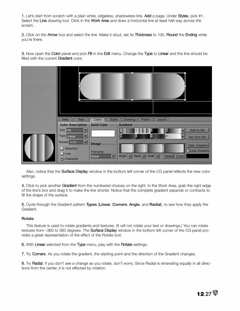
11.. Let’s start from scratch with a plain white, edgeless, shadowless line. AAdddd a page. Under SSttyylleess, pick #1.Select the LLiinnee drawing tool. Click in the WWoorrkk AArreeaa and draw a horizontal line at least half way across thescreen.
22.. Click on the AArrrrooww tool and select the line. Make it stout, set its TThhiicckknneessss to 100. RRoouunndd the EEnnddiinngg whileyou’re there.
33.. Now open the CCoolloorr panel and pick FFiillll in the EEddiitt menu. Change the TTyyppee to LLiinneeaarr and the line should befilled with the current GGrraaddiieenntt color.
Also, notice that the SSuurrffaaccee DDiissppllaayy window in the bottom left corner of the CG panel reflects the new colorsettings.
44.. Click to pick another GGrraaddiieenntt from the numbered choices on the right. In the Work Area, grab the right edgeof the line’s box and drag it to make the line shorter. Notice that the complete gradient expands or contracts tofill the shape of the surface.
55.. Cycle through the Gradient pattern Types (Linear, Corners, Angle, and Radial), to see how they apply theGradient.
Rotate
This feature is used to rotate gradients and textures. (It will not rotate your text or drawings.) You can rotatetextures from –360 to 360 degrees. The SSuurrffaaccee DDiissppllaayy window in the bottom left corner of the CG panel pro-vides a great representation of the effect of the Rotate tool.
66.. With LLiinneeaarr selected from the TTyyppee menu, play with the RRoottaattee settings.
77.. Try CCoorrnneerrss. As you rotate the gradient, the starting point and the direction of the Gradient changes.
88.. Try RRaaddiiaall. If you don’t see a change as you rotate, don’t worry. Since Radial is emanating equally in all direc-tions from the center, it is not effected by rotation.
12.27

Selection, Line, & Character
If you have multiple lines of text on a page, you can choose how the texture will be applied.
SSeelleeccttiioonn automatically sizes the texture to on everything selected.
LLiinnee applies the texture independently to each line, automatically sizing to the line.
CChhaarraacctteerr applies the texture independently to each character, automatically sizing to the character.
11.. AAdddd a Page. Under SSttyylleess, pick #1. In the TTeexxtt PPrrooppeerrttiieess panel, LLoocckk tthhee AAssppeecctt RRaattiioo, set WWiiddtthh andHHeeiigghhtt to 45, TTrraacckkiinngg to 5, LLeeaaddiinngg to 30. Type in:
You’re only givenA little spark of madness. You mustn’t lose it.
Robin Williams
22.. Click on the AArrrrooww tool. Hit CCttrrll ++ aa to select all the lines. CCeenntteerr them.
33.. Now go to the CCoolloorr panel and in EEddiitt, choose FFiillll. In TTyyppee, pick LLiinneeaarr.Choose a nice simple GGrraaddiieenntt.
44.. Cycle through the SSeelleeccttiioonn, LLiinnee and CChhaarraacctteerr choices. Notice how the gra-dient spreads differently.
12.28

Image
When you choose TTeexxttuurree in the TTyyppee menu, CG looks for an image to texture map on the selected surface.You select the image by clicking the triangle in the FFiilleennaammee box and hitting LLooaadd.
Browse to your image in the File Requester,select it and hit OOppeenn. The image will automati-cally size itself onto the surface. If you createdthe image with an alpha channel, the alpha infor-mation will be maintained.
11.. AAdddd a Page. Under SSttyylleess, pick #1. In theVViieeww panel, turn on the SSaaffee AArreeaa view. Draw aFFiilllleedd RReeccttaannggllee in the upper left corner of theinner Safe Area.
22.. Select the box and hit CCttrrll ++ cc to CCooppyy it. AndCCttrrll ++ vv to PPaassttee it. The copy will be right on topof the original. Click on the selected box (theoriginal) and drag it to the middle. CCooppyy andPPaassttee again. Drag this box to the bottom right. Ifyou’re ambitious, you can add more boxes.
33.. CCttrrll ++ aa to select all of the boxes. Go to theCCoolloorr panel, under TTyyppee, choose TTeexxttuurree.
NNOOTTEE
The default image named hello looks suspiciously like a whole wheat flour tortilla.
Under IImmaaggee, browse to YellowFlower.jpg (that came on the VT [3] Content CD) or pick a favorite image.
44.. If you have SSeelleeccttiioonn chosen, then the image will map itself across the boxes.
12.29

Pick LLiinnee and the image will automatically size on to the individual boxes.
CChhaarraacctteerr is not applicable withobjects.
HHIINNTT
If you select the boxes one at atime, you can apply differentimages to each.
Gradient
The Character Generator, under the CCoolloorr tab, offers a range of ready-made gradients that you can chooseor edit. You also can make your own that you can save.
Making a Gradient
A gradient is a gradual mixture of two colors.
11.. To begin, AAdddd a new page. Draw a large FFiilllleedd RReeccttaannggllee and select it. In the CCoolloorr panel, in EEddiitt choose FFiillll,and in TTyyppee select LLiinneeaarr.
22.. The simplest gradient is one from black to white, which is what you get when you click CClleeaarrGGrraaddiieenntt. If you look closely, at each end of this gradient are two dotted vertical lines. These arethe nodes.
Click on the node on the left. Notice that the color box below LLoooopp GGrraaddiieenntt is highlighted. Click in the boxto bring up the Color Picker. Choose a baby blue. It immediately replaces the black in the gradient, which nowgoes from blue to white.
12.30

33.. Click on the node on the right. Click in the Color box and choose a kelly green. Your gradient now goes fromblue to green.
44.. You can add more colors. Double-click in the middle of the gradient to add a node. Click in the Color boxand choose a canary yellow. Now the gradient goes from blue to yellow to green.
55.. Click on the middle node and drag it to the left to shorten the blue to yellow ramp and lengthen the yellow togreen. You also can use the Move slider to move a highlighted node.
66.. Now, highlight the two end nodes by clicking on one and then holding down CCttrrll and clicking on the other.Play with the SSccaallee key, which expands or contracts the space between two nodes.
77.. Choose the middle node. If the CCoolloorr PPiicckkeerr isn’t open, click on the Color box to open it. Slide the BBrriigghhtt toolto the right to increase the brightness of the color.
If you keep making the yellow brighter, you’ll notice in the upper right of the Color Picker that a message willpop up: WWaarrnniinngg:: CCoolloorr iiss nnoott BBrrooaaddccaasstt SSttaannddaarrdd!!
If you will be showing your graphics on a regular TV, you need to darken the yellow until the warning goesaway. (You can read more about this warning in Chapter 13.)
88.. To delete a node, select it and hit the DDeelleettee button below the Gradient window.
99.. Sometimes you want to make part of the gradient a solid color. For example, you want a solid yellow in thecenter. Click on the yellow node and hit the CClloonnee button. A second yellow node is created and is slightly offsetfrom the first. Drag it to the left and the color between the two nodes will be yellow.
If you select both nodes, you can Brighten, Move, or Scale them together.
1100.. Now, with the Filled Rectangle selected, go back to Color Description and cycle through the remaining gra-dient TTyyppeess: CCoorrnneerrss, AAnnggllee, and RRaaddiiaall.
12.31

Loop Gradient
If you want a gradient to be seamless, then the same color has to be on both ends. If you checkmark LLooooppGGrraaddiieenntt, CG makes the gradient seamless.
Saving a Gradient
When you create a gradient that you want to save, click AAdddd ttoo BBiinn and the gradient will be numbered andstored at the end of the bin.
Of course, if you see a gradient in the bin that offends your aesthetics, you always can dispatch it to thenetherworld of bad taste by clicking DDeell ffrroomm BBiinn. However, once deleted, it’s gone. You cannot undo this com-mand.
STYLES
This panel is really straightforward. The Character Generator comes packaged with a range of styles that youcan apply to both text and objects. Each style usually defines the Fill and Edge colors, and often includes theShadow color.
12.32

The easiest way to view them is to type something out, add a Rectangle, hit CCttrrll ++ aa to select them both,and cycle through the Styles.
HHIINNTT
Studying styles can be extremely helpful when you are designing your own. If you load a style, open theText, Color, and Drawing panels to see how the style achieves a certain effect.
Of course, if you see a style that you would never use, click to select it and hit the DDeelleettee buttonnext to the bin.
If you create a combination that you’re especially proud of, click on the AAdddd button and thestyle will be numbered and added to the end of the bin.
FILEBIN
Loading a Background Image11.. Click on the FFiilleebbiinn tab to open the Filebin.
22.. Browse to the folder with the image you want. Click and drag the file onto the WWoorrkk AArreeaa.
12.33

33.. Like every other object in the WWoorrkk AArreeaa, to move it, select it first. If the image is video resolution, you shouldbe able to align it with the Safe Area guidelines.
44.. You can reshape and resize the image just like the objects you created with the Drawing Tools. And you canadd edges and a shadow. In fact, when you load a background image, it adopts the characteristics of the cur-rent style.
55.. You can load as many background images as you like. Though, if you are creating a multi-image mosaic, itwould be more efficient if you to make it in a paint program like Aura and import a single completed image.
LAYOUT
LayersEach line of text in the Character Generator is considered a separate object just like one created with the
Drawing Tools. Each object has its own layer. Initially, the layers are arranged in the order they were created.The most recent is on the top; the first is on the bottom.
11.. AAdddd a page. Type in: TTeexxtt 11.
22.. Now draw out a FFiilllleedd RReeccttaannggllee bigger than Text 1. Select it and give it another color.
33.. Drag the rectangle over the word and it will cover it, because the box is the layer above the word.
Reordering Layers
The Layout panel provides two methods of moving layers.
44.. Type in: TTeexxtt 33. Select it and give it a third color. And drag it on top of the rectangle. Now, you have threelayers on your page: the two lines of text and the rectangle object.
55.. Click the LLaayyoouutt tab. Initially, thepanel displays the layers in the orderthey were created, which means thatthe item on the bottom of the list is thetop layer. That’s right, the bottom is thetop.
66.. In this example, we want to put the rectangle below Text 1. So click onFFiillllRReeccttaannggllee in the list to highlight it, and under LLaayyeerr, click on UUpp. (Remember,pushing something up the list will push it down the layer stack.)
12.34

If the rectangle was covering theText 1, it now should be behind Text 1and Text 3.
77.. If FFiillllRReeccttaannggllee is selected and youhit FFrroonntt,, the item will jump to the topof the stack (the bottom of the list). Ifyou now hit BBaacckk, it will jump to thebottom of the stack.
88.. You also can click an item and dragit up or down the list.
HHIINNTT
This Layout list can be very helpful in selecting items that are overlapping. Instead of trying to select themon the Work Area with the Arrow tool, just open the Layout panel and highlight them on the list. This tech-nique is especially useful when selecting and deselecting a background image that covers the wholeWork Area.
Depth
Layers also can be rearranged on a page with the Depth tool at the top of the CGpanel. First, you select the object you want to move, clicking the left arrow will drop theobject one layer in the stack. Hitting the right arrow will raise the object one layer.
Aligning Layers
The Layout panel provides some basic tools for aligning multiple objects.
NNOOTTEE
Do not confuse alignment with justification. Alignment positions objects with a selected object, not withthe margins of the page or the safe area.
99.. Move TTeexxtt 11 to the upper right side of the Work Area. Leave the rreeccttaannggllee where it is.
1100.. Select them both andunder Align in the Layoutpanel, hit HHoorriizzoonnttaall. The twowill align horizontally. Noticethat since TTeexxtt 11 is not ashigh as the rreeccttaannggllee, it willalign to the middle of therectangle from top to bot-tom.
12.35

NNOOTTEE
The last layer selected is the anchor for the alignment. If you select rectangle last, Text 1 will jump toalign to it.
1111.. Now, hit VVeerrttiiccaall and the text will align to the middle of the rectangle from left to right.
1122.. If you choose LLeefftt, then the left edges of the selection boxes will align. RRiigghhtt, and the right edges align.
Adding TransparencyLet’s bring a number of the features together with this example.
11.. AAdddd a page. Open the FFiilleebbiinn and browse to MMaannggooss..jjppgg (in the VT [3] Manual Content CD) and drag it intothe WWoorrkk AArreeaa. Move it so it fills the Work Area.
22.. Type in MMaannggooss. Give it a solid dark blue color. As mentioned above, you probably will need to open theLLaayyoouutt panel to select items.
33.. For the background for the text, let’s make a rectangle and add rounded ends. Since Filled Rectangles donot have ends to round, draw a LLiinnee,, select it and size it appropriately, and set TThhiicckknneessss to 150. Select EEnnddiinnggand make it RRoouunndd.
12.36

Give the line a different color from the Mangos text.
44.. Move the text over the left side of the line and centered up and down. And move them both just inside theupper left side of the text Safe Area.
55.. Now, with the Line selected, open the CCoolloorr panel. Under TTyyppee change SSoolliidd to LLiinneeaarr. To the right, clickCClleeaarr GGrraaddiieenntt. In the GGrraaddiieenntt window, click on the node on the left. Now, below LLoooopp GGrraaddiieenntt, right-click inthe GGrraaddiieenntt CCoolloorr window to activate the EEyyeeddrrooppppeerr tool. Drag the Eyedropper onto the Work Area and selectthe yellow on the mango image.
Click the right node, and as before, use the Eyedropper to pick the darkest orange of the mango image.
You have just made a gradient from yellow to orange. Next, we’ll add the transparency.
66.. To bring up the CCoolloorr PPiicckkeerr, click in the GGrraaddiieenntt CCoolloorr window for this right node. In the AA (Alpha) window,type in 125 and hit EEnntteerr, which makes this orange about 50% transparent. So our gradient now goes from anopaque yellow to a 50% transparent orange. You should see the mango image showing through the right sideof the line.
12.37

77.. One last step. In the GGrraaddiieenntt window, double-click (about ¼ of the way from the left side) to add a node. Ifyou click in the Gradient Color window, the Color Picker will show you this new nodes color and Alpha value,(depending on exactly where you clicked it should be around 225).
88.. Slide this node to the right.Notice that you are not onlyextending the yellow, but youalso are making the back-ground behind the text lesstransparent.
12.38

CREATING A MOTION PAGEThe first step to making a scroll (text and objects moving vertically) or a crawl (text and objects moving hori-
zontally) is to set the PPaaggee TTyyppee (top left of the CG panel) to MMoottiioonn PPaaggee. Your Work Area will sprout ScrollBars on the right and bottom, which will be handy to see the sides of long crawls or the top and bottom ofextended scrolls.
Motion Panel The MMoottiioonn PPaanneell contains the tools to create both scrolls and
crawls. You access the Motion panel by clicking on the MMoottiioonn tab in theupper left of the CG panel. This is where you control the direction,speed and behaviors of your crawls and scrolls.
Direction
The Direction arrows are self-explanatory. If you want your crawl to gofrom left to right, you pick the right pointing arrow. Scrolls moving up,you choose the up arrow, etc.
End Behavior
• OOvveerr tells the CG to scroll or crawl the page once, then stopwhen the page has left the screen.
• SSttoopp tells the CG to scroll or crawl the page once and then tohold on the last line of text.
• LLoooopp tells the CG to loop the page continuously.
• LLoooopp aadddd FFrraammee tells the CG to loop the page continuously andto place a blank frame between each loop iteration.
HHIINNTT
Type End or another indicator at the end of your scroll so that you can verify when the scroll leaves thescreen. You can make the End text invisible by selecting it and checkmarking the Do Not Render optionin the Text Properties panel.
Speed Control
There are two related boxes to set the speed of the motion. In the top box, you can enter a specific speed.The measurement is in pixels per frame. If you are doing a crawl across the screen, that’s 720 pixels by 30frames per second (NTSC). So if you want to have an object or text to crawl from one side to the other in fourseconds, then 720 divided by 120 equals 6. That is one of the ten default speeds provided in the drop downmenu in the lower box – the bigger the number, the faster the motion.
HHIINNTT
If you play the motion pages too fast, the motion will not be smooth. An old rule of thumb was a line oftext should take about seven seconds to travel from the bottom of the screen to the top. You will needto test the speed out on a TV monitor.
12.39

Sending CG to the SwitcherThe buttons below the speed controls give you options for sending your CG
creations as output to the Switcher. Motion pages are loaded and run from theDSK (Downstream Key). For details on the DSK, see Chapter 9. The DSK keyson alpha and by default CG Motion pages have alpha. Even though the WorkArea has a black background, in actuality, the CG page produced has a trans-parent background, which allows the Switcher’s Program Out to show through.
HHIINNTT
Since the Motion pages are playing from the DSK, they overlay any transitions made to Program Out inthe Switcher.
Cue
CCuuee sends the current CG Motion page to the Switcher, where it turns on the DSK and activates ProgramOut. Cue also puts the CG on an available Switcher channel. However, the page will not play until you hit GGoo.
NNOOTTEE
When you hit Cue, the Output to Switcher box in the CG’s View panel is checkmarked.
Go
GGoo launches your CG motion page on the Switcher. When you click GGoo a second time, the motion page isremoved from the Switcher. Even if it is not finished, it disappears.
If you haven’t hit Cue or turned on Output to Switcher, when you hit GGoo, the motion page will preview inthe CG Work Area and will not play in the Switcher. Again, be advised to not judge the quality of the motionfrom this preview.
Creating a Crawl
1. To begin, AAdddd a new page and change the PPaaggee TTyyppee to MMoottiioonn PPaaggee.
2. Next, you usually type out an interminable list of names that lasts longer than the opening of the original StarWars movie. You can do that on your own. Let’s make a crawl without any text. Open the DDrraawwiinngg TToooollss andpick the FFiilllleedd AArrcc. Choose a nice bright yellow and make an object, like the one in the image below, with aradius of around 70. (You should have the Drawing panel at the bottom open also.)
3. Select the object and Copy (Ctrl + c)and Paste (Ctrl + v). The clone will be righton top, just drag it off to the left. Changeits Radius to 80.
12.40
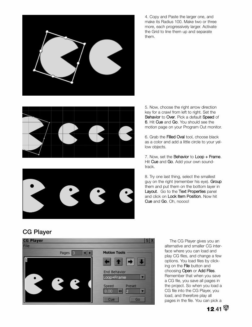
4. Copy and Paste the larger one, andmake its Radius 100. Make two or threemore, each progressively larger. Activatethe Grid to line them up and separatethem.
5. Now, choose the right arrow directionkey for a crawl from left to right. Set theBBeehhaavviioorr to OOvveerr. Pick a default SSppeeeedd of66. Hit CCuuee and GGoo. You should see themotion page on your Program Out monitor.
6. Grab the FFiilllleedd OOvvaall tool, choose blackas a color and add a little circle to your yel-low objects.
7. Now, set the BBeehhaavviioorr to LLoooopp ++ FFrraammee.Hit CCuuee and GGoo. Add your own sound-track.
8. Try one last thing, select the smallestguy on the right (remember his eye). GGrroouuppthem and put them on the bottom layer inLLaayyoouutt. Go to the TTeexxtt PPrrooppeerrttiieess paneland click on LLoocckk IItteemm PPoossiittiioonn. Now hitCCuuee and GGoo. Oh, noooo!
CG PlayerThe CG Player gives you an
alternative and smaller CG inter-face where you can load andplay CG files, and change a fewoptions. You load files by click-ing on the FFiillee button andchoosing OOppeenn or AAdddd FFiilleess.Remember that when you savea CG file, you save all pages inthe project. So when you load aCG file into the CG Player, youload, and therefore play allpages in the file. You can pick a
12.41

page by number from the PPaaggeess requester box. Of course, the CG Player’s compact design precludes display-ing thumbnails of the pages, so you’re flying blind. The preferred method for live playback is to load the cgpages into a DDR that is assigned as the DownStream Key.
The playback controls are the same as the full CG panel. And the Cue and Go buttons are still the keys toplacing and playing pages on the Switcher. To affect any other aspect of the CG, such as its overall appear-ance, you must work in the main Character Generator.
Working with Templates The templates that are packaged with the Character Generator are a great resource. But if you will be editing
them, you will need to know how they are constructed.
1. Click on the TTeemmppllaatteess tab in the upper right of the CG panel. Scroll down to number 1177, which isCCoommmmeerrcciiaall 44. Click IInnsseerrtt and the template will be inserted into your CG project as a page that can be edited.
2. Since this page has an image in it. Grab the edge of the CG panel and pull it out to enlarge the interface,which will allow you to see around the outside edges of the Safe Area. Now, click on the AArrrrooww selection buttonand then CCttrrll ++ aa to select all the items on the page.
3. Open up the LLaayyoouutt panel and scroll through the listing.
12.42

You can learn a lot from studying this list. Especially note which items are grouped together, which will beimportant information if you want to change one of the elements.
4. For example, if you want to change 22000000 to 2200..0000, 2000 is grouped with $ and Cash Back. You can change2000 without UnGrouping them, but if you want to realign 20.00 and Cash Back, you will need to UnGroup.
5. Again, examine how Tim Johnson has created these templates. If you see a type style or drawing style thatyou like, grab it. For example in 96, CutNPaste, select the green pie chart, which will load its Style into theColor panel.
Open the SSttyyllee panel and click AAdddd to store that style for future use.
12.43

6. You can save Gradients also. For example, number 63, LowerThird4, has an unusual Gradient.
Select the FFiilllleedd RReeccttaannggllee with the gradient, open the GGrraaddiieenntt tab and click on AAdddd ttoo BBiinn.
Creating a Bug
Bugs are the not so endearing term given to those little TV network logos that you see on almost everychannel now. They are easy to make in the Character Generator, which, depending on whether bugs bug you,may not be a good thing.
1. The key to making a bug is that your image needs a transparent background. Luckily, the CharacterGenerator by default makes images with a transparent background, which may not be obvious because it putsblack, and not a checkerboard pattern, to represent the background.
The other thing to remember is that you make the bug the size that it will be on the TV screen. Again, sinceCG shows you the Safe Areas, you have a great guide for size and location.
2. You have all the tools that you need. For example, to create the ArtTV logo used in the Switcher chapter, animage of a palette was imported into the background of the CG and was used to model an object with theFilled Close Spline tool.
3. Apply a blue gradient, addsome text and for a final touchattach a soft shadow to thepalette object, which will becast on the underlying video.You can load it directly into theDSK of the Switcher by clickingon OOuutt ttoo SSwwiittcchheerr under theVViieeww tab.
Or if you want to save for later use in a VT-Edit project, then click File atthe top of the CG panel.
Choose SSaavvee IImmaaggee FFiillee…… In the File Requester, give it a name. Makesure to save it in an image format.
If you save it as a ..ttggaa (targa), it will maintain its alpha infor-mation, including the shadow.
You can now bug the world.
12.44

I n video productions, Keying has proved a popular and powerful method of combining or superimposing twoimages – whether stills, video clips or live camera shots. The process involves revealing the background
image by eliminating a portion of the foreground image (cutting a keyhole) based on the foreground’s brightnessor luminance values (luma key) or on its color or chrominance values (chroma key).
When keying in video and film, the foreground footage is often shot in front of a blue or a green screen. Forexample, when you see a television meteorologist in front of a weather map, that person is actually standing infront of a blue or green screen, which is chroma keyed out exposing the background map.
HINT
In the past, blue was typically used for keying because that color is found less often in skin tones.Recently, green screen has become more common. Keep in mind that when you use a blue or greenscreen, it can bounce light and tint the person or object in front of it. To reduce this problem, have thetalent stand farther from the key wall, to avoid the spill. Another trick is to backlight the talent with amber-gelled lights, (if using a bluescreen), which reduces the blue color spill on their hair and shoulders.
VT [3] offers two tools for keying: the Keyer (which contains both luma and chroma key functions) and theCross Keyer (which is a more powerful chroma keyer). This chapter discusses these tools in the context of theSwitcher. (VT-Edit has its own luma and chroma keying tools, which are discussed in Chapter 8.)
13.1
Chapter 13: Chroma andLuma Keying

To maintain graphics or titles over your Switcher output, (like those omnipresent TV network bugs), you usethe DownStream Key. (The DSK function is explained in Chapter 9.)
Basic Setup for Keying with the Switcher 11.. To see either the Keyer or Cross Keyer in action, open the Switcher from the Main Menu. If the 8 or 16Input Switcher skin is not up, right-click on the Switcher panel and choose one of them under Available Skins.
22.. If you are using video or stills for your foreground image, open aDDR (Digital Disk Recorder) and load the footage. The DDR tagshould appear on a channel on your Switcher. (If it doesn’t, drag theDDR tag from its panel down to a channel.) You will need to open asecond DDR for your background images. Make sure that DDR’s tagshows up on your Switcher.
33.. Route the DDR with your foreground image to the Key bus. This isthe image or video out of which you will cut a key.
44.. Above the T-bar is a box labeled Lock Key. For now, checkmarkit. This function locks the Preview bus to the same input that is onthe Key.
55.. Now, route the DDR with the background image tothe Main bus.
66.. To see your keying operations, open two VT-Visions. Set one of them to PGM and the other toKey.
77.. Now, open the Keyer. You access it from the MainMenu in the Control Room functions.
You also can bring up the Keyer from the tabs on the right of the Switcher’s 8 and 16 Input skins.
If you opened the Keyer panel from the Main Menu, selectthe Normal skin since it is the reference in this chapter. (Right-click on the panel and choose Normal from the AvailableSkins.)
13.2

NOTE
The two Keyer interfaces look a little different, but the functionality is the same. You can work in one orthe other; VT [3] will not let you work in both at the same time. For example, if you click on the LumaWhite button in the Switcher interface, a black circle indicates that it is active. Now, if you go to the sep-arate Keyer panel and click on the Luma Key White button, it highlights and the button on the Switcherinterface becomes inactive.
Luma White and Luma BlackLuma White keeps the darkest information in your foreground image and keys out (makes transparent) the
bright areas of the image. Thus, you replace the brightest areas of your foreground image with your backgroundvideo.
Luma Black does the opposite of Luma White: you keep the brightest information in your foreground imageand key out the dark areas of the image, replacing them with the background video.
13.3

Luma Keying is especially useful with the Character Generator. If you create your titles with white or light col-ored letters on a black background, then by choosing Luma Black, you simply key out the black. Or you canuse it with black and white images to create custom transitions and special effects.
When you work with the Luma Keyer, you’re not limited to just the extremes of black or white. You canchoose a color and use the luminance value of the color to set a threshold for keying. For example, you canchoose a yellow with a luminance value of 200 and use Luma White to key out all other pixels with the sameluminance value and every pixel with values above 200 notwithstanding its color. If you switch to ChromaKeying with that same pixel value chosen, the Keyer then uses the color value for the pixel, in this case yellow,to key out only pixels of the same yellow color.
Linear White and Linear BlackLinear White keeps the dark areas of your foreground image, and uses a linear gradient to key out the light-
est information. The lightest areas of the foreground image are keyed out completely. Other light areas arekeyed out along a scale so that you get smooth areas where the background video blends with the gradient.
Linear Black does the opposite, keeping the light areas of your foreground image and using a linear gradientto key out the dark areas.
Tolerance
When you are Luma Keying, Tolerance specifies the range of luminancevalues to include when you key. A low Tolerance setting permits only val-ues that are near the value of the Luma Key you choose. As you increasethe Tolerance setting, you include more luminance values.
NOTE
With the Default Keyer skin, (called Normal in the interface), you adjust Tolerance by rotating the knob.When the knob is rotated all the way counterclockwise, (the dot on the knob is at about 7 o’clock), thenumerical equivalent is 0. Rotate it all the way clockwise, (dot is at 5 o’clock) and the value is 100. TheSmoothing wheel operates the same way. If you prefer numerical displays, other Keyer skins display themfor Tolerance and Smoothness.
Smoothing
In most keying situations, you want to eliminate the sharp edges where your background and foreground meet.The Smoothing operation produces a blur effect on the edges of a key. Usually lower Smoothing values willprovide a soft professional edge, while higher values can make an interesting aura or dream effect.
Contract
For fine-tuning of a key, the Contract dial allows you to contract or expand the key without blurring it orsharpening it. This function is very useful for keying compressed sources since it allows you to trim the keyedge in slightly.
Luma Keying Step by Step 11.. Begin by setting up your Switcher and desktop as described in the steps above. For this example, loadfan.tga into one DDR and ChineseDancer.tga into a second DDR. (All the images used in this chapter can befound on the VT [3] Manual’s Content CD.)
22.. In the Keyer, start with both Smoothness and Tolerance at 0. Select the Luma Key White option (on theSwitcher, it’s called Luma White).
13.4

33.. Put your foreground image, fan.tga, on the Key bus. It should be visible in the VT-Vision set to Key. This isthe image that we will cut our key from. Make sure that the Lock Key box is checked.
44.. Put ChineseDancer.tga in the Main bus. This is the image that will be revealed when the Luma Key isapplied to fan.tga.
55.. Adjust the Tolerance to key out the white in fan.tga. As soon as you set the Tolerance past 0, on the VT-Vision set to PGM, you can see the white disappear and the background show through the keyhole.
66.. Adjust Smoothness to clean up the edges of your image. Remember that Smoothness is a fine adjustment,so increase it little by little.
77.. Adjust Contract to trim the edge of the key.
HINT
Keying is part science and part art. As you experiment with the controls, you will get a feel for what com-bination of Tolerance, Smoothing, and Contract work best in each situation.
88.. Now try this. Open a third DDR and add Pink.rtv into it. Uncheck the Lock Key box and route this DDR tothe Preview bus. By unchecking the box, you can put different images on each of the busses.
You will see on your PGM VT-Vision that the foreground image has changed, but the key cutout remains thesame. That’s because the keying operation is applied to the image on the Key bus, therefore determining theshape of the key. The Preview bus just supplies the foreground image. Now, in the DDR with LamparaLoop,checkmark Loop and play the clip.
13.5

HINT
As was discussed in the Switcher chapter, the VT [3] card can only handle two live video sources at once.So you can only have two cameras coming into the keying process on the Switcher. But you could havethree computer-generated sources as Key, Main, and Preview, such as video playing from three DDRs.
Chroma KeyWith Chroma Key, you use the Pick Color tile to choose a color from your foreground video. Areas of the
image with that color are keyed out so that your background video shows through. You can pick your color byusing the Eyedropper Tool (described in the Step by Step below) or from the Color Picker panel, which popsup if you left click on the Pick Color tile. (For more information about working with the Color Picker panel, seeChapter 14.)
Tolerance
In Chroma Keying, Tolerance determines the amount of color variance from your base key color. For exam-ple, if your base color was RGB 150, 150, 150 then a Tolerance of 1 includes only colors with values of 149 or151 for any of the RGB components.
Smoothing
Works the same in Chroma Keying as it does in Luma Keying.
NOTE
Smoothness helps eliminate the blue or green glow around talent caused by light reflecting from the back-ground screen. However, as you increase smoothness, people in your video can become transparent.Smoothing should be increased by fine increments.
Contract
Also works the same in Chroma Keying as it does in Luma Keying.
Presets
In the Normal Keyer skin (and in the Keyer tab on the Switcher), you can save four favorite key setups asPresets that you can recall later. Once you created a Key combination that you like, click Store, and thenselect one of the numbered buttons, 1 – 4. The setting will remain until you Store another one over it. To recallit, simply click on the corresponding number.
Saving Module ConfigurationsRight-clicking in the Keyer panel brings up the Context Menu. The same Preset functions can be accessed
here. Also if you want to save your Module Configurations with a meaningful label instead of a Preset number, clickSave… In the File Requester, browse to the Configurations folder that you created and squirrel that config away.
13.6

HINT
Since the VT [3] works in 4:2:2 uncompressed video space, achieving good results (pulling a clean key)is enhanced. When you work with a chroma key, using the highest quality images makes pulling a cleankey easier. The best sources for keying include a live component camera input or an SDI signal from adigital tape deck. Images from component tape decks are also good. Because of compression artifacts,pulling a good key from NTSC DV tape (which works with 4:1:1 color) can be difficult. The process canbe slightly easier with PAL DV because it has 4:2:0 color. Composite signals also can be problematic.
Chroma Keying Step by Step11.. Begin by setting up your Switcher and desktop as described in the steps above. For this example, loadHowardBlue.avi into a DDR. Place it on the Key bus. You should see it in the VT-Vision set to Key. On theSwitcher, make sure Lock Key is checkmarked.
22.. Load PurpleSky.tga into the second DDR and put it on the Main bus.
33.. If you don’t have the Keyer open, load it either from the Main Menu or the Switcher tabs. Click the ChromaKey button to activate it.
44.. Both Keyer interfaces have a box with a color in it, (the Pick Color tile). Right-click on the tile and the cursorbecomes an Eyedropper. Hold the mouse button down and drag the Eyedropper over the blue background inHowardBlue.avi in the VT-Vision set to Key. Release the mouse button over your chosen color (in this case,blue) and it appears in the Pick Color tile.
55.. Adjust the Tolerance to key out the blue. As soon as you set the Tolerance past 0, on the VT-Vision set toPGM, you can see the blue disappear and PurpleSky.tga show through.
66.. Adjust Smoothness to clean up the edges of your image. Remember that Smoothness is a fine adjustment,so increase it little by little.
77.. Adjust Contract to trim the edge of the key.
NOTE
You might see jaggies around the edge of the key; but as was mentioned at the beginning of the chap-ter, using a DV source for keying will not give the best results.
Like the Luma Key example, you could turn off Lock Key and add a third image or video to the Preview bus.
13.7

Cross KeyerVT [3]’s Cross Keyer widens your key color choices beyond the solid background colors available with a reg-
ular chroma keyer. With it, you can key out a complicated background by specifying multiple colors withoutaffecting the rest of the image.
The Cross Keyer panel contains a display similar to a vectorscope that is really an overlay of a concealedcolor wheel, which you can use to select key colors.
TIDBIT
Did you know that the Cross Keyer was named after its creator, Dr. Andrew Cross, NewTek’s VicePresident of Software Development? Alas, the Cross Fade has a much less reputable pedigree.
Cross Keyer Step by Step11.. As with Chroma Keying, you need video or images for your foreground and background. Since the CrossKeyer can key a range of colors, you can choose a foreground image that is more complicated than a green-screen shot.
22.. Set up the Switcher and your desktop as earlier.
33.. Load the Cross Keyer from the Control Room tools in the Main Menu. Highlight the Active button and setSmoothness and Tolerance to 0. (The knobs should be turned all the way counterclockwise, to about 7o’clock.)
13.8

44.. For this example, let’s move your patio plants to the woods. Load FondaPlants.tga in a DDR. It will serve asthe Key image. Load ThickTrees.tga into a second DDR and place it on the Main bus.
55.. You can select your key colors in two ways. Usually the most effective method is to pick your colors directlyfrom the foreground image. To do that, start by choosing the Paint button. Move your mouse over the VT-Vision window set to Key and the cursor turns into a Paintbrush icon. If you hold your left mouse buttondown, you can “paint” or select different colors that will be keyed out of your foreground image. If you look atyour PGM VT-Vision, the keying occurs as you paint. (The color selection also will be reflected in the CrossKeyer’s vectorscope display.)
You can click once to choose a specific pixel, or hold the mouse and drag to choose as you move. Whenyou release the mouse button, you keep any colors that you’ve already chosen. To select colors in another partof your image, click again. As long as the Paint button is active, you can add more colors.
Try to key out most of the FondaPlants background. Be careful not to run your Paintbrush over the grayborders of the VT-Vision skin. If you do, you will select that color.
66.. To deselect colors, hold the Shift key while you drag in the area of the screen that you do not want to bekeyed. To deselect all the colors, click on the Clear button in the Cross Keyer panel.
77.. To return your cursor to its normal functions, you will need to turn off the painting tool. Either press theSpacebar or click off the Paint button.
88.. Adjust the Tolerance to tweak your keying. Notice that when you twist the knob, the color display in the vec-torscope window expands, indicating that you are including a wider range of pixels in your key selection.
99.. To clean up the edges, adjust Smoothness. Notice that the vectorscope color display blurs.
13.9

Selecting colors from the Cross Keyer’s vectorscope displayThe alternative method of choosing key colors is by painting directly on the Cross Keyer’s vectorscope
screen. Though this technique usually is not as easy to use, it can be effective if you have a specific range ofcolors that you want to key out.
11.. With this way of selecting colors, you do not have to highlight the Paint button. Simply move your cursor intothe vectorscope display and the icon will change into a Paintbrush.
22.. Click and drag in the window to select your key colors. Imagine the display as one big hidden color wheel.(With a little experimentation, you can see where all the colors are.)
44.. As you “paint,” you can see those colors keyed out of the foreground image in the PGM VT-Vision window.
55.. Like the previous method, to deselect colors, hold the Shift key when you’re painting.
66.. Adjust Tolerance and Smoothness.
HINT
You can alternate between techniques of picking key colors. You might find it useful to select the colorsby painting on the VT-Vision window and cleaning up your choices by erasing on the vectorscope dis-play.
As with Luma and Chroma Keying, you can put a separate image or clip on the Preview bus. But again, theonly way to have three separate sources for Main, Preview, and Key is for at least one of them to be computer-generated (the Background Generator, Character Generator, DDR, or Aura).
PresetsThe Normal Cross Keyer skin also has Preset buttons for saving and recalling four favorite color key setups.
Begin by creating a color key painting, and then click Store, (it will light up), and finally select one of the num-bered buttons, 1 – 4. (the number will light briefly and then turn off with the Store light. The setting will remain atthat Preset until you Store another one over it. To recall it, simply click on the corresponding number.
Saving Module ConfigurationsRight-clicking in the Cross Keyer panel brings up the Context Menu. If you want to save your Module
Configurations with a meaningful label instead of a Preset number, click Save… In the File Requester, browse tothe Configurations folder that you created and store that config for a rainy day.
13.10

Choosing color is essential to specific areas of the VT [3]: for font attributes, for graphics and for keying. InVT [3], you also can color-code panels and files. The Color Picker looks and works similarly to the standard
color pickers found in paint programs like Aura.
Basic Setup1. Load the Color Picker from the Graphics section of the Main Menu.
2. Alternatively, you can access the Color Picker from the Background Generator, the Keyer, and theCharacter Generator.
3. The Color Picker display is self-contained, so you do not have to open a VT-Vision.
Palette of Color Swatches
At the top left of the panel is a palette of 98 color swatches that you can customize.
14.1
Chapter 14: Color Picker
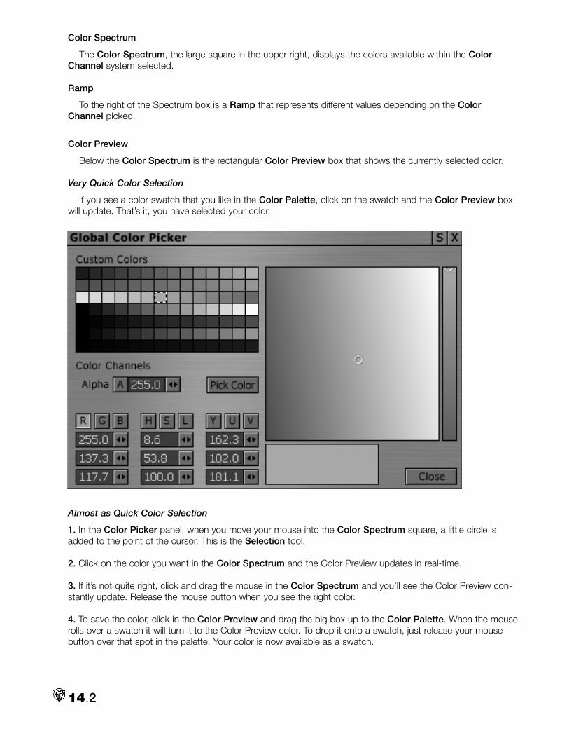
Color Spectrum
The Color Spectrum, the large square in the upper right, displays the colors available within the ColorChannel system selected.
Ramp
To the right of the Spectrum box is a Ramp that represents different values depending on the ColorChannel picked.
Color Preview
Below the Color Spectrum is the rectangular Color Preview box that shows the currently selected color.
Very Quick Color Selection
If you see a color swatch that you like in the Color Palette, click on the swatch and the Color Preview boxwill update. That’s it, you have selected your color.
Almost as Quick Color Selection
1. In the Color Picker panel, when you move your mouse into the Color Spectrum square, a little circle isadded to the point of the cursor. This is the Selection tool.
2. Click on the color you want in the Color Spectrum and the Color Preview updates in real-time.
3. If it’s not quite right, click and drag the mouse in the Color Spectrum and you’ll see the Color Preview con-stantly update. Release the mouse button when you see the right color.
4. To save the color, click in the Color Preview and drag the big box up to the Color Palette. When the mouserolls over a swatch it will turn it to the Color Preview color. To drop it onto a swatch, just release your mousebutton over that spot in the palette. Your color is now available as a swatch.
14.2

TIP
If you don’t see the color that you want in the Color Spectrum, try clicking on another one of the nineColor Channel buttons in the bottom left of the panel. For example, if R is highlighted, select B. Noticethat the color range changes in Color Spectrum. If you still don’t see the color you want, let go, go wild,and punch all the buttons.
Alpha Channel
The Alpha, or A, option lets you apply transparency to a color. Alpha values range between 0 and 255,where 0 is completely transparent and 255 is completely opaque. (When you click on A, the Ramp displays theAlpha range.)
f CU of A channelColor Channels
Below the Alpha box are the channels where you can mix new colors. The color systems represented areRGB, HSL, and YUV.
NOTE
Any value that you enter in any of the three color systems affects the other two because they are adjust-ing to reflect the new color.
14.3

Image: CPPanel.tif CU of color channelsRGB Channels
RGB stands for Red, Green, and Blue. You can set values for each field between 0 and 255. 255 in all fieldsmakes white, and 0 in all fields makes black. When you adjust the values in the RGB fields, you can see theSelector (that small circle) move around the Color Spectrum. (You also can move the Selector in the Spectrumwith your mouse.) The Color Preview updates to show your current color. The values for the other systems alsoupdate.
HSL Channels
HSL stands for Hue, Saturation, and Luminance (or Lightness). You change the Hue value, or pure color, indegrees between 0 and 360. (It works on the principle of a color wheel.) Adjusting the S value changes theintensity of your color. The color selector moves more towards the edges of the Color Spectrum for colors withstronger intensity (higher values) and toward the middle for colors with less intensity. When you change the Lvalue, you change the luminance of the image. S and L accept values between 0 and 100%.
YUV Channels
YUV represents Y (luminance) and UV (chrominance); these fields accept values between 0 and 255. Whenyou change the Y value, you adjust the brightness of the image. Larger U values shift the color towards blue,smaller U values shift it towards yellow. Larger V values shift the color towards red, smaller V values shift ittowards green.
Channels and the Spectrum
You can select a different channel to view in the spectrum, which also changes the display in the ramp. Toactivate a specific channel, click on a letter in that Channel. The spectrum will change to a graphic representa-tion of the values for your current choice in that channel. The color preview will not update until you move thecolor Selector in the spectrum or in the Ramp.
Creating a Custom Color with the Channels
1. Open the Color Picker from the Main Menu.
2. Under the RGB buttons, place the mouse cursor in the first field (R).
14.4

3. If you click and drag across any number already in the box, it will highlight in blue. Now, any new numericvalue that you type will replace it. Type in 200. If you now hit Enter, the cursor will jump to the next field. (Youalso can use the arrow slider controls to the right of the box to click and drag new numbers.)
4. In the second field, type in 200, Enter. In the bottom field, type in 0. tif
5. The Color Preview updates in real-time as you change the values.
6. As before, you can add your new custom yellow to the Color Palette, by clicking in the Color Preview boxand dragging the color onto one of the swatches in the Color Palette.
Pick Color/Eyedropper
The Pick Color button lets you use the Eyedropper tool to choose a color from anywhere on the VT [3] inter-face.
1. Roll your mouse over the Pick Color button and the cursor changes to an Eyedropper icon.
2. Now, click on the button and hold as you drag the Eyedropper around the interface. The Color Previewupdates in real-time as you drag the eyedropper over different colors.
3. When you find the color you want, release the mouse button to accept it.
TIP
The Eyedropper function is great when you want to match a color in a video clip because you can roll theEyedropper over an image on your VT-Vision monitor and pick a color from it.
Illegal Colors
If you choose a color outside the video palette – an “illegal” color – a message appears in the panel, abovethe Color Spectrum box, (squint your eyes), exclaiming, “Warning: Color is not Broadcast Standard!” Usuallythis means that the color cannot be accurately represented by YUV values. The color may work in video, but itwill not accurately display for broadcast television. For example, a computer can display a black RGB value of0,0,0; but U.S. NTSC televisions cannot. U.S. NTSC black is a setting on the Waveform monitor of 7.5 IRE,which has an RGB value of 15,15,15. Anything below that value is considered “Super Black” and cannot bedisplayed properly on screen.
WARNING
Adjusting the YUV values with the arrow keyscan cause the other panels to display numbersout of their normal ranges (for example, RGB:380, 193, -22). This is an artifact of how the colorsystems interact and is not a concern unless youreceive the illegal color warning.
14.5

NTSC and PAL
You can specify whether the colors you create are intended for NTSC video or PAL video. NTSC video is thestandard used for television in the U.S., Japan, and some parts of South America. PAL video is the standard formost European television. The default for VT [3] is U.S. NTSC. To configure VT [3] for PAL, open thePreferences panel in the Main Menu. Under System > Video Mode, choose PAL (720 x 576). (For moreinformation, see Chapter 3.)CP8.tif
Also in Preferences, under System > Output Pedestal Mode, if you set it to Off (0 ire), you change thepedestal to the Japanese NTSC standard.: CP9.tif
Accessing Your Colors
The Color Picker is the same across VT [3] panels – no matter if you access from the Background Generator,the CG, or from the Main Menu. Any changes that you make will be saved and displayed the next time youopen the Color Picker. This is a good thing because you can access your customizations at any time, as longas you don’t copy over that color.
WARNING
Because there is only one Color Picker, you need to remember that once you make a change, that’s it.There is no undo. So if you create a color or palette that you really like, read on.
Saving Palettes
You can save your complete custom Color Palette in two ways. One method is to right-click in the ColorPicker panel to open the Context Menu, and under Presets > Store, choose one of the four Store options. Torecall the setting, simply pick the corresponding number under Presets > Recall.
Or, if you want to name your pet polychromatic palette something memorable:
1. Right-click on the Color Picker panel. In the Context Menu, under Module Configuration, choose Save…
2. In the File Requester, browse to that VT3 Configurations folder that you have already made (hint, hint), andname and save this Color Picker configuration.
3. To recall it, select Load… from the Context Menu.
14.6

Tinting with the Color Picker
In Chapters 3 and 5, you learned that you can tint panelsand files. Basically, you drag and drop a swatch from theColor Picker onto the panel or file. To tint certain panels thataccept color as input (Background Generator, Keyer, andCharacter Generator), you must hold the Ctrl key while youdrag and drop the swatch.
NOTE
You cannot tint the Switcher.
Closing the Color Picker
When you close the Background Generator or any otherpanel from which you accessed the Color Picker, you alsoclose the Color Picker. The only time that the Color Pickerdoes not automatically close is when you choose it from theMain Menu. Again, the current Color Picker settings arestored when the panel is closed and reappear wherever thepanel is opened.
Color Theory for Broadcast Television 101Color is defined by two fundamental methods, each with their own set of primary colors. The traditional theo-
ry used in painting is called Subtractive Color, with its primaries: Red, Yellow and Blue. We perceive an object’scolor by the wavelengths of light it reflects. All the other wavelengths are absorbed, or subtracted, by theobject. When all three primary colors are combined, no light is reflected, giving us the color, black.
In the video and computer world, Additive Color theory is commonly used. It defines how we perceive colorby combining (adding) wavelengths of light to form the visible spectrum from its primary colors of Red, Greenand Blue. In a traditional (cathode ray tube) TV or computer monitor, the image on the screen is generated byfiring three (red, green, blue) components from electron guns in the picture tube, which make the phosphors onthe screen luminescent. The resulting color for each pixel is a mix of the three primary colors determined by theamount of energy in each electron stream.
Each of the RGB components is described in eight bit values, 0 to 255. In Additive Color theory, the maxi-mum combination of RGB, (255, 255, 255), is white, which translates to 100% luminosity. Since luminescenceplays an integral part in the equation, the old HSV or “Hue, Saturation and Value” scheme is referred to as“Hue, Saturation, and Luminance” or HSL.
In most video, the YUV system is the standard color system, and it also uses a scale between 0 and 255 forall values. The YUV system relies heavily on sending picture information through Y (luminance), which is theblack and white part of an image. The video signal sends less information for U and V, which are the B-Y andR-Y color (chrominance) parts of the image.
Colors defined digitally in the computer tend to render brighter when translated to analog TV signals. Intense
14.7

saturated colors (e.g. RGB: 255, 255, 0) can produce images that flare or smear on an NTSC analog TV set.Even if your computer generated graphics are in the “NTSC legal” range, they should be previewed on anNTSC monitor. If they don’t reproduce well, lower the luminosity or saturation.
Tricks for Customizing your Color Palette Quickly changing the color of a swatch
1. Right-click on a swatch in the Palette (the cursor changes to the Eyedropper icon) and hold the mouse but-ton.
2.a. Now, drag the Eyedropper over any color on your desktop. Wherever you release the mouse, that colorreplaces the swatch in the Palette. Notice that it does not affect the Color Preview window because you areonly choosing a color for the swatch.
Or try this.
2.b. Click on a swatch to select it and then use one of the methods on page 14.2 to change the color. (Drag inthe Spectrum or enter values in the Color Channels field). With this method, you change both the swatchcolor and the Color Preview color.
Creating a Swatch with Transparency
1. Select a swatch in the Palette.
2. In the Alpha Channel box, enter a value of 100, making the swatch semi-transparent. Remember Alpharanges from 0 (totally transparent) to 255 (totally opaque).
Or click the A button and the Ramp to the right of the Color Spectrum box will change to represent thetransparency range. The top of the Ramp is opaque; the bottom is transparent. (The more checkerboard pat-tern you can see, the more transparent the color). You can click in the Ramp to choose an Alpha value and thedisplays will update.
14.8

Range of Colors in the Palette
You can create a range of colors, such as a range of blues from light to dark, or create a range of trans-parencies for colors. In the examples outlined below, you place the range on one row, but you can always cre-ate a range that covers the whole palette.
Range of Colors from Dark to Light
1. Select the swatch on the top left of the Color Palette and make it dark blue.
2. Place a white swatch on the far right of the same row.
3. Click on the blue swatch; then shift-click on the white swatch to make the swatches between become inter-mediate levels of blue.
Range Between Two Colors
1. Drop down a row. Make the first swatch on the left red.
2. On the end of the row, make the swatch yellow.
3. Click on the red swatch, then shift-click on the yellow swatch. The swatches between the two fill with colorsthat range between red and yellow.
Transparency Range
1. Drop down to row 3. Make the first swatch on the left green.
2. On the end of the last row, make the swatch the same green color, but also change its Alpha value to 0(100% transparent).
3. Now, click on the green swatch in row 3, then shift-click on the transparent green swatch. The swatchesbetween the two turn green but fill with transparencies that range between opaque to transparent.
age: NOTE
Remember to save your favorite palettes.
14.9

Notes:
14.10

I n the 20th Century, every self-respecting TV studio would include a Background Generator (BG) for creatingbackgrounds for titles or other graphics. Now, many of the complicated graphic tasks are handled by image
processing software like Aura. But for quick basic jobs, VT [3]’s Background Generator offers you four optionsfor making smooth, clean, video resolution backgrounds: Solid, Horizontal gradient, Vertical gradient and 4Corner gradient.
Basic Setup
1. Select the Background Generator from the ControlRoom section of the Main Menu.
2. A BG tag should appear on a channel on your Switcherand load into the Preview bus. To route BG to Main, pick iton the Switcher.
3. If you don’t have your Switcher open, right-click on the BGtag (at the bottom left of the BG Panel) and select Put ontoMain In.
4. To view the Background Generator output, open VT-Vision(and click it to Main) or have an NTSC monitor connected.
NOTE
The 8 and 16 input Skins for the Switcher contain aBG tab, which allows you to access the BG functionsdirectly from the Switcher.
15.1
Chapter 15: BackgroundGenerator

The BG relies on the Color Picker, so refer to the Chapter 14 for information on creating colors.
FeaturesSolid Background
To create a background with only one color, choose the Solid option. Click on any of the four tiles to launchthe Color Picker and select a color. The Background Generator fills all four tiles with your chosen color.
NOTE
To use dithering in the Background Generator, activate the option on the Preferences panel (OtherModules > Dither Black Background). Choosing On will eliminate banding if you dissolve to and fromthe background color. Turn dithering Off to make a clean black signal.
Horizontal Gradient
Choose the Horizontal button, then click on one of the tiles in the left column. Choose a color, and theBackground Generator applies that color to both tiles in the left column. Then click on a tile in the right column,and choose another color. In VT-Vision, you see a two-color gradient that flows from left to right.
15.2

Vertical Gradient
Choose the Vertical button, then click on one of the tiles in the top row. Choose a color, and theBackground Generator applies that color to both tiles in the top row. Do the same for the bottom row. The gra-dient will flow from top to bottom on your output screen.
4 Corner Gradient
For the 4 Corner gradient, you choose a different color for each tile, and the Background Generator createsa gradient that blends these colors from each corner.
To assign the same color to more than one tile, first select multiple tiles by Ctrl-clicking. Then choose acolor. You can create diagonal gradients this way.
Presets
In the Normal BG skin, you can save four favorite sets of backgrounds as Presets that you can recall later.
1. Begin by creating a set of backgrounds, (Solid, Horizontal, Vertical, and 4 Corner).
2. Then click Store, and select one of the numbered buttons, 1 – 4. Your set of backgrounds will remain untilyou Store another set over it.
3. To recall, simply click on the corresponding number and all four backgrounds will load up.
15.3

Saving a Module ConfigurationIf you have more important things to remember than what’s behind
Store #1, you can save your backgrounds with a meaningful name –Cerulean Skies or Sizzling Sienas.
1. When you have created your polychromatic backgrounds, right-click on the BG panel. In the Context Menu, under ModuleConfiguration, choose Save…
2. In the File Requester, browse to that VT3 Configurations folderthat you have already made (hint, hint), and name and save this BGconfig.
3. To recall it, select Load… from the Context Menu.
Saving a Background as an RTVSince you can route the BG directly into the Switcher, you don’t need to save the image if you stay in the
Switcher context. But if you want to use a background in the Character Generator or ToasterEdit, you need toconvert it to a still image.
1. Start by placing the BG into the Main bus.
2. Open the Capture panel. Under the Format tab, select NewTek RTV file (video).
3. Under Options, Input = Main In. The Video box (not Audio) is checked. Timed is checked. In the Framesbox, enter 1.
4. In the Record tab, name your background, pick its path and click Record. (For more information on theCapture panel, see Chapter 7.)
Tinting the Background Generator PanelLike the other panels in VT [3], you can tint the Background Generator panel. But because the BG accepts
color as an input, you can’t simply drag and drop from the Color Picker onto the panel. To tint the BG, youmust open the Color Picker, select a color swatch and then hold the Ctrl key as you drag and drop theswatch onto the BG panel. To revert back, right-click in the BG panel and choose Color Tinting > ClearCurrent Shading.
NTSC and PAL SettingsWhen you change between PAL and NTSC in the Preferences, any Background Generators that are running
will automatically switch mode. The default for VT [3] is U.S. NTSC. To configure for PAL, open the Preferencespanel. Under System > Video Mode, choose PAL (720 x 576). For more information, see Chapter 3.
15.4

WWAARRNNIINNGG
This chapter is for the serious technogeeks in the audience. You are about to enter the land of IREs andgraticules. But if your videos will ever be shown on a TV set, you’ll be glad that you know this stuff. Sobuckle up. If you make it through, you’ll have earned your Alien Technology merit badge.
V iva the desktop video revolution! The problem is that broadcast television started over 40 years before therevolution. And computer monitors do not always give a reliable representation of what the video signal will
look like when it is displayed on a TV set. You need an objective way to ensure that you are producing crisp,legal video.
TV professionals rely on two pieces of equipment to verify and calibrate their video signals: the waveformmonitor and the vectorscope. VT[3] bundles both of these tools into one panel. This 60 field-per-second NTSCdisplay, (50 field-per-second PAL), gives you a quantitative view of your signal by measuring its brightness andcolor values.
The real-time vectorscope/waveform monitor displays the data from the signals on the Program and Previewbusses of the Switcher. Vectorscopes and waveform monitors complement one another and fully represent allthe information about the video signal. A waveform monitor measures the luminance, or brightness, of a picture.A vectorscope calibrates the color and levels in a video signal.
16.1
Chapter 16: VT-Scope &Processing Amplifier

These tools are excellent resource for tasks like objectively measuring the signals from multiple cameras soyou can adjust their scanning and colors to match when switching between them, or verifying that a recordingmade with a standard amplitude video signal at the machine’s input will produce standard amplitude video at itsoutput during playback.
Test SignalsTo test your system and equipment, a well-defined, highly stable test signal with known characteristics, such
as color bars, is required. If the system can pass the test signal from input to output with little or no distortion, itcan cleanly pass picture signals as well.
A test signal generator (TSG), such as the NewTek Calibar, produces a set of precise video signals with care-fully defined and controlled characteristics. Each signal is ideal for verifying one or more specific attributes of thevideo system. Most semi-professional cameras can produce a color bars signal. These test signals serve as areference that should be “perfect,” so you can identify problems when they are not perfect.
This chapter identifies the correct display that you should see when you send test signals to the VT-Scope.To remedy distorted signals, you either need to correct your input equipment or adjust the signal using aProcessing Amplifier (Proc Amp). (Luckily one is provided with VT [3].)
Basic Setup11.. Load the VVTT--SSccooppee from the MMaaiinn MMeennuu under PPrroodduuccttiioonn DDeesskk.
22.. Open a DDDDRR and click AAdddd MMeeddiiaa. Find and load the nnttsscc__ccoolloorrbbaarrss__7755..rrttvv that is in the VT3 directory >EEffffeeccttss > EEffffeeccttss.
NNOOTTEE
You can use this still image of color bars to give you an idea of how a perfect signal should look on awaveform and vectorscope. But a still image does not supply all the video information needed to do allthe adjustment. You really need to supply your own video colorbars, either from a camera or playing froma tape deck. If you have one handy, use it as the source.
33.. Right-click on the DDR tag in the panel and choose PPuutt oonnttoo MMaaiinn IInn.
44.. For visual reference, open a VVTT--VViissiioonn. Click the MMaaiinn button.
55.. Finally, on the VVTT--SSccooppee panel, under IInnppuutt, select PPrroogg for Program Out.
16.2

Refresh
The VT-Scope offers two refresh rates for viewing the waveform monitor or the vectorscope. SSllooww uses lessprocessing power and allows you to maintain more than one VT-Scope panel on your desktop. Fast needsmore CPU muscle and if your machine is puny, you may want to show only one VT-Scope panel. Fast will giveyou a smoother, less jittery display.
NNOOTTEE
Many systems sample only a single line of video to produce waveform/vectorscope signals. VT [3]’s usesthe full video frame as professional hardware units do.
WaveformYou access the waveform portion of the VT-Scope by choosing one of its options at the bottom of the panel:
YC, Y, C, YUV, and RGB. With your video source loaded into the Switcher, the YC option displays its Y (lumi-nance) and C (chrominance) signals together, while Y shows only luminance and C only chrominance.
When you choose either the YUV or RGB options, three columns of graphs appear. The YUV graph displaysseparate columns for each of the Y, U, and V signals. YUV represents a composite signal including sync andthe graph shows how luminance and chrominance are combined in one signal. The RGB option generates sep-arate columns for the R, G, and B signals.
16.3

The waveform monitor is read from left to right: the signal on the left side of the waveform corresponds toinformation on the left side of the video picture
In image below, you see the luminance information for a color bars signal. Notice that the signal toward theleft sits at 100. This is the IRE measurement for a white luminance value.
16.4

NNOOTTEE
Even if you feed a single color to the waveform monitor, you may still see spikes or discrepancies becausein the digital world, the video signal is synthesized.
Luminance Signal
The luminance of a video signal is measured on a scale of 7.5 to 100 for North American NTSC. By under-standing the scale you can modify a signal that goes above the 100 mark or below the 7.5 mark. Signals thatfall outside of this range lose all detail. For example, if a light-colored face goes above 100 units, it will bewashed out. A dark-colored face that falls below 7.5 units will be too dark to show any detail. Faces in the +50to +80 range are usually considered properly exposed.
Color Bars and the Waveform Monitor
When you send a color bars test signal to the waveform monitor, you should see the following: • Waveform black level at 7.5 IRE (U.S. NTSC)• Waveform luminance (white bar) at 100 IRE
VectorscopeA vectorscope displays information only about the chrominance (color) portion of the video signal. U.S. televi-
sion is built around three primary colors: red, green, and blue. A mathematical formula encodes color informa-tion for broadcasting, but that formula must have a reference point, or color burst. The color burst appears onthe vectorscope, along with other colors in the video picture.
16.5

You access the vectorscope by choosing 100% or 75% mode under the Vectorscope heading at the bottomof the panel. The 100% and 75% labels refer to the saturation of the colors in the signal. Usually you use colorbars signals with vectorscopes – 75% and 100% full field color bars and the SMPTE color bars. You use theappropriate mode with its associated test signal so that you can correctly place the dots generated for the signalvalues. Thus, if you sent a 75% Color Bars test as your input, you select the 75% mode for the vectorscope.
NNOOTTEE
The vectorscope shows no luminance information at all. You can see this if you generate a red back-ground on the Background Generator. Then add white to the red so it’s more pink. The signal on the vec-torscope still stays the same.
Chrominance Signal
Vectorscopes work well with a color bars signal while you adjust the signal with a processing amplifier. Eachbar of the color bars signal creates a dot on the vectorscope’s display. Where these dots fall in relation to tar-gets in the graph and the phase of the burst vector gives you information about the status of the chrominance(color) signal.
CCoolloorr BBaarrss aanndd tthhee VVeeccttoorrSSccooppeeWhen you send a color bars test signal to the vectorscope, you should see:
• A bright dot in the center of the display• Color burst straight out on the horizontal axis extending to the 75% mark.• Dots in the targets for each of the colors in the color bars.
HHIINNTT
This is a highly unusual suggestion for a manual to make, but if you need a magnifying glass to see thosedots in the vectorscope, try setting your monitor display to 800 x 600. The vectorscope is much morevisible. The problem is, VT [3] was not designed for this resolution. Some of the panels won’t functionproperly at this resolution and all the skins look horrible. But if you are trying to make some critical adjust-ments, 800 x 600 really helps. Just promise to put the resolution back to at least 1280 x 1024 right after-wards. And if anybody asks, you didn’t hear it from me.
16.6

PROCESSING AMPLIFIERThe Processing Amplifier (Proc Amp) lets you balance and refine the video signal from an input source by
adjusting its luminance and chrominance information. With a Proc Amp, you can polish good video and oftenrepair problems like oversaturated or faded colors, unnatural flesh tones, and inadequately lit scenes. For exam-ple, you can use the Proc Amp to balance two cameras to get the same tone from both.
When you make adjustments with the Proc Amp, you change the actual signal as it feeds through VT[3], notjust the display on a monitor. So when you record the signal from the ProcAmp, you record your adjustmentsas well. The Proc Amp works intimately with the VT-Scope.
NNOOTTEE
Be judicious with the Proc Amp; it’s easy to overdo it. While VT[3] can handle oversaturated colors, yourrecording equipment may not be so forgiving. And realize that some footage is simply unrecoverable withProc Amp adjustments. You may need a time base corrector (TBC) to stabilize the output of a crankyvideo deck.
Interface
Once again, the creative mindsof Team NewTek have provided anassortment of elegant to funkyskins. For the discussion in thischapter, the Pro skin will be thereference because it contains all ofthe component adjustment set-tings: Brightness, Contrast, Hueand Saturation, along with U andV Offset and U and V Gain.
16.7

Basic Setup11.. From the MMaaiinn MMeennuu, open the SSwwiittcchheerr, a PPrroocc AAmmpp, a VVTT--SSccooppee and a VVTT--VViissiioonn.
22.. Open a DDDDRR and load nnttsscc__ccoolloorrbbaarrss__7755..rrttvv that is in the VVTT33 directory > EEffffeeccttss > EEffffeeccttss.
33.. Put the DDR on the Main bus of the Switcher. Set the VVTT--SSccooppee and the VVTT--VViissiioonn to PPrroogg//PPGGMM.
Selecting a Source for the Proc Amp
You pick the source that the Proc Amp will adjust by right-clicking on the Proc Amp tag marked IInnppuutt, (bot-tom left of panel), and choosing the source from the list. If you have an SX-8 attached, your list will be longerthan the one on the next page. This Context Menu also lets you specify commands related to the Switcher andoutput.
16.8

NNOOTTEE
If you have an SX-8, you can open theSSXX--88 VViirrttuuaall BBOOBB from the MMaaiinn MMeennuu. Ifyou right-click on a Virtual BOB input andchoose EEddiitt PPrroocc AAmmpp sseettttiinnggss ffoorr tthhiissiinnppuutt, VT[3] launches the Proc Amp. VT[3]stores 80 different settings for inputs,which is to say that you can store separatesettings for every available input for NTSCand PAL. VT[3] also stores separate set-tings for different users.
44.. In the PPrroocc AAmmpp panel, right click in the IInnppuutt window (bottom left). From the menu, choose DDiiggiittaall DDiisskkRReeccoorrddeerr.
55.. Now as you adjust the Proc Amp settings, you will see the results on the VT-Vision and the VT-Scope.
66.. As you begin experimenting, remember this trick as a failsafe. If at any time you wish to reset all the buttonsto the Bypass settings, right-click on the panel to bring up the Context Menu. Under DDeeffaauulltt SSeettttiinnggss, you havetwo options. If you have created a refined setting for your global defaults, RReeccaallll BByyppaassss SSeettttiinnggss returns you tothose values. If you have not stored new Bypass settings, then click on RReeccaallll FFaaccttoorryy SSeettttiinnggss and every but-ton jumps back to the VT [3] default values. Either choice is different than clicking on the BByyppaassss button. (Seepage 16.11.)
Brightness
The Brightness control adjusts the luminance (lightness and darkness) of the video signal.
• Rotate the knob clockwise to decrease Brightness and darken the image.• Rotate counterclockwise to increase Brightness and lighten the image.
16.9

HHIINNTT
If you make a change in a setting, you can go back to the default by double-clicking the knob. For exam-ple, if you twist the brightness knob to 65, you can double-click it and it will return to the default of 50.
If you set your waveform monitor to Y, when you increase the brightness control to maximum, you can seethe Y signal rise to 110 IRE, (the 7.5 black will go to 100). It sinks toward 0 IRE when you decrease the control,(the white drops to 7.5).
NNOOTTEE
Luminance (brightness) values go back to the early days of TV, which was initially in black and white. Thecolor signal piggy-backs on top of the black and white (luminance) signal so both can be broadcast simul-taneously.
Contrast
The Contrast control adjusts the levels of gray in the signal, which affect the brightness and saturation of animage. If you look at the waveform set to Y, you can see the levels of gray as steps. Decreasing Contrastmakes those steps closer together and turns your picture grayer. Increasing Contrast makes those steps fartherapart.
• Rotate the knob clockwise to increase Contrast; the image appears brighter and more saturated.• Rotate counterclockwise to decrease Contrast; the image appears darker and less saturated.
An image with extreme areas of darkness and lightness might benefit from reduced Contrast. If your footagelooks washed out, try increasing Contrast.
Hue
The Hue control adjusts the relative phase of color and is monitored using a vectorscope with a color barssignal. On the vectorscope you can see the signal cycle around a color wheel as you rotate the Hue control.
You might use the Hue control when you have a video signal making a person look too green. You wouldrotate the control to the right toward red.
Saturation
Saturation is the intensity of color in the video signal. Low saturated pictures look gray and overly saturatedimages show colors that bloom to the point of smearing.
• Rotate clockwise to increase Saturation.• Rotate counterclockwise to decrease Saturation.
On the vectorscope, you can see the signal spread or shrink when you adjust saturation.
A video where colors seem too intense, (especially with bleeding colors), would benefit from decreasedSaturation. Red colors are particularly susceptible to bleeding in composite and Y/C signals.
If you turn Saturation all the way to the left, you remove all color, hence resulting in black and white video.
U Offset
The U portion of the YUV signal carries the blue and green color information. Offset is similar to Hue, exceptwhen you adjust the U Offset, you rotate only in relation to the blue/yellow portion of the video signal.
• Rotate U Offset clockwise to shift the signal toward blue. • Rotate U Offset counterclockwise to shift the signal toward yellow.
Adjusting U Offset will shift the signal horizontally in the vectorscope.
16.10

V Offset
The V portion of the YUV signal carries the red and green color information. Offset is similar to Hue, exceptwhen you adjust the V Offset, you rotate only in relation to the red/green portion of the video signal.
• Rotate V Offset clockwise to shift the signal toward red. • Rotate V Offset counterclockwise to shift the signal toward green.
In the vectorscope, the signal will shift vertically.
U Gain
The U portion of the YUV signal carries the blue and green color information. Gain is similar to Saturation,except when you adjust the U Gain, you increase or decrease the saturation of the blue/yellow portion of thevideo signal.
• Rotate clockwise to increase blue and yellow saturation.• Rotate counterclockwise to decrease blue and yellow saturation.
The U Gain control is used with a vectorscope and color bars to correct the white balance of a signal. Withregular video on a vectorscope, tweaking the V Gain causes the signal to bloom over the blue and yellow seg-ments or contract away from them.
V Gain
The V portion of the YUV signal carries the red and green color information. Gain is similar to Saturation,except when you adjust the V Gain, you increase or decrease the saturation of the red/green portion of thevideo signal.
• Rotate clockwise to increase red and green saturation.• Rotate counterclockwise to decrease red and green saturation.
The V Gain control is also used with a vectorscope and color bars to correct the white balance of a signal.With regular video on a vectorscope, tweaking the V Gain causes the signal to bloom over the red and greensegments or contract away from them.
Bypass
The Bypass button lets you toggle between your original input and the adjustments you made with the ProcAmp, so you can compare the two in VT-Vision. When you activate Bypass, you temporarily turn off any adjust-ments you made.
16.11

Auto Calibration (Auto Cal)
This is an extremely handy tool especially for those that don’t like to get their hands dirty under the hood. Itmakes all the adjustments and you don’t need to fiddle with knobs like U Offset and V Gain.
If you are adjusting a camera, feed a color bar test signal generated by that camera into the Proc Amp. HitAAuuttoo CCaall. From the pop-up window, select whether it’s a 75% or 100% signal. Automagically, VT [3] adjusts allthe Proc Amp controls to bring the signal into alignment. Of course, you should judge for yourself if the newsettings look just right. If you are calibrating a video deck, play a tape with color bars on the deck and selectthe deck’s input as the source for the Proc Amp.
The CCaalliibbrraattee uussiinngg lloooopp--tthhrroouugghh option in Auto Calibrate will then use the values obtained from the initialcalibration and repeat that for all other similar inputs. So, the action of selecting one composite input and cali-brating it can be repeated to all other composite inputs in the system.
Track Preview
The Track Preview option only appears on your Proc Amp panel if you have the SX-8 breakout box. WithTrack Preview on, you can apply the Proc Amp to the source that sits on the Preview bus of the Switcher,avoiding opening a proc amp panel for every source coming into the Switcher. Instead, you adjust the procamp settings for the current Preview input. The adjustments that you make to the input remain with that inputas long as it is on the Switcher. So if you move to a different Preview source, you don’t have to worry aboutlosing your Proc Amp settings.
NNOOTTEE
When you drop a tag from a Switcher source into the Proc Amp, it will turn off Track Preview automati-cally and lock the Proc Amp to that input.
Presets
In the NNoorrmmaall and PPrroo Proc Amp skins, you can save four favorite sets of Proc Amp set-ting as Presets that you can recall later. These presets remain until you replace them, soyou can shutdown VT[3] and access them at a later time.
11.. Begin by adjusting the Proc Amp as necessary.
22.. Then click SSttoorree, and select one of the numbered buttons, 11 – 44. Your current Proc Ampsettings have been stored and will remain there until you SSttoorree another set over them. Ifyou return the Proc Amp to its default settings or make more adjustments, you can easilyrecall the preset that you stored.
16.12

33.. To recall, simply click on the corresponding number and all Proc Amp buttons will jump to their spots.
Saving a Module Configuration
If you have more important things to remember than what’s behind Store #1, you can save your back-grounds with a meaningful name – SlightlyBlueCamera2.
11.. When you have created your propitious Proc Amp settings, right-click on the Proc Amp panel. In theCCoonntteexxtt MMeennuu, under MMoodduullee CCoonnffiigguurraattiioonn, choose SSaavvee……
22.. In the FFiillee RReeqquueesstteerr, browse to that VT3Configurations folder that you have already made(hint, hint), and name and save this Proc Amp config.
33.. To recall it, select LLooaadd…… from the CCoonntteexxtt MMeennuu.
Advanced Settings
In the CCoonntteexxtt MMeennuu, you find a menu item for Advanced Settings Panel. This launches a panel with optionsfor finer control over the Proc Amp. The first few options are identical to the buttons that you see in the ProcAmp panel, except you adjust them with sliders instead of knobs. The full specifications for the remainingparameters are available in a technical document from NewTek.
WWAARRNNIINNGG
This panel is meant for expert users. We do not advise that you change these parameters without guid-ance from NewTek technical support.
Defaults
You can Store and Restore settingsin the Context Menu of the Proc Amppanel. If you want to restore the defaultsettings for the Proc Amp, that is to setthem back to the settings shown whenyou first launched the panel, you canchoose RReeccaallll FFaaccttoorryy SSeettttiinnggss.
16.13

Choose SSttoorree aass BByyppaassss SSeettttiinnggss if you want to use your adjustments as the standard settings for the ProcAmp. Then you can choose RReeccaallll BByyppaassss SSeettttiinnggss and get back to your changes.
On/Off
When you close the Proc Amp panel, the most recent settings for a particular input are automatically saved.The desktop saves all Proc Amp settings so that from one use of VT[3] to the next you do not lose any ProcAmp configurations. However, if you want to save a specific proc amp setting, save and name the Module con-figuration in the Context Menu.
Processing Amplifier and VT-ScopeThe Proc Amp and the VT-Scope work together to help you identify and correct signal problems. The VT-
Scope measures the signal and the Proc Amp lets you make adjustments to the signal. Before you work withthe procedures that follow, you should read the VT-Scope section, which explains how to interpret the signalson a vectorscope and a waveform monitor.
Color Bars Test Signal
As stated previously, you need a test signal generator or a professional video camera to create the ColorBars Test Signal. The colors in the color bars signal have different luminance levels, and the bars are arrangedby level from highest to lowest: white, yellow, cyan, green, magenta, red, blue, and black.
Color bars test signals fall into two categories: 100% bars (full amplitude) and 75% bars (reduced amplitude).You usually use 75% bars for basic testing because 100% bars contain signal levels that may be too high topass through a system without distortion. At some point, however, you will need a 100% white reference levelfor checking overall signal amplitude. Many 75% color bar test signals have a 100% white level for this purpose.
16.14

NNOOTTEE
You really need to supply your own test signals to run through these adjustments. Still color bar imagescannot give you a sync signal to see and adjust.
When you look at the luminance of a signal, a correct test signal for color bars appears undistorted on awaveform monitor. It is therefore a perfect signal. You want the signals that you send through your equipment,like a VTR, to match this perfect signal, so you can recognize when the signal is distorted.
Amplitude (Waveform Monitor)
You measure amplitude against the horizontal axis on the waveform monitor at 0 IRE. Click the YY setting onthe waveform. The blanking level should align with the 0 IRE line and the 100% white reference level shouldalign with the 100 IRE line. The black level, or setup, should be at 7.5 IRE (for North American NTSC). A specialdashed line sits at 7.5 IRE so you can verify black level.
• If the signal’s 100% white level does not align with 100 IRE, you adjust the Brightness control on theProc Amp, which also should bring the black level to 7.5 IRE.
• After you check amplitude, you need to check the sync pulse level. Sync pulse should sit at -40 IRE. Ifsync is off by more than a few IRE units, check your equipment for a sync amplitude adjustment andchange it to -40 IRE. Luminance and sync must both be correct. This is viewed with Waveform’sChrominance, or C mode.
• If you cannot get the signal to align at all three points (white at 100 IRE, blanking at 0 IRE, and sync at-40 IRE) you should get your equipment serviced.
Chrominance Gain (Waveform Monitor)
After you check luminance gain you need to check chrominance gain. Incorrect chrominance amplitudesmean that the video saturation is affected. The color burst should range from -20 to +20 IRE and maximumchrominance levels of the first two color bars (yellow and cyan) should be at exactly 100 IRE. If they are not,adjust the chrominance gain (U Gain and V Gain) to correct the levels. This is also measured in the waveform’sChrominance view.
16.15

16.16
Chrominance Phase (Vectorscope)
To check the signal from a VTR with a reference signal, you must play back a videotape with the 75% colorbars recorded. Select the VTR on the Switcher and look at the vectorscope display.
The burst phase should align on the horizontal axis and the dots should sit within their targets, otherwiseyour signal has a problem with chroma phase. If the dots are rotated, then chrominance phase is incorrect rela-tive to the color burst. Hues will look wrong—faces appear green or purple, for example. You must have correctchrominance phase, even if you don’t see obvious hue errors on a picture monitor.
To correct chrominance phase
11.. Align the vectorscope’s burst display with the horizontal axis. The burst should be perfectly centered in thecircle.
22.. Adjust Hue, U Offset, and V Offset to get the dots as close to their targets as possible. They may be too nearthe center of the display or too far away, but they will lie in the proper direction from the center when phase iscorrect.
You may need to toggle between chrominance gain (discussed next) and phase adjustments to get the dotsin their boxes. The dots rarely center exactly in the targets. They should fall somewhere within the small targetsrather than the larger boxes.
Chrominance Gain (Waveform Monitor and Vectorscope)
Adjusting chroma phase alone may not put the dots in their boxes because they may fall short of, or extendtoo far outside, the boxes. This means you need to adjust chroma gain.
To check chroma gain for a VTR, you use the color bars signal recorded at the head of the tape. You shouldcheck luminance levels on the waveform monitor, and correct any errors, before you make any measurementswith the vectorscope.

To correct chrominance gain
11.. Use BBrriigghhttnneessss to adjust the white level on the waveform monitor to 100 IRE. Then switch to the vec-torscope.
22.. While your tape plays the color bars, dots appear on the vectorscope. If the dots sit above their targets onthe vectorscope, chroma amplitude is too high. If the dots fall short of the boxes, chroma is too low.
33.. Adjust the SSaattuurraattiioonn, UU GGaaiinn, and VV GGaaiinn controls so that the dots fall into their targets.
If you adjust chroma gain and the dots do not fall into the targets, you may need to re-adjust hue or get theequipment serviced.
If the tape plays past the color bars signal into video, you’ll see the vector change because video usually hasno large areas of primary or secondary colors to create the bar dots. The display looks fuzzy or blurred becausethe vector shows the blend of hues within the picture.
Using the Proc Amp to Tint Skin TonesFor these tasks, you will make someone look green, or blue, or warm, which will give you an idea of how the
controls affect the tinting of human skin tones. Remember though, that the best way to balance video is to usethe test signals with the VT-Scope. Also remember that you should not use VT-Vision to monitor a signalbecause it is basically a computer monitor. You should use an external NTSC or PAL monitor.
Part I. Green with Envy
11.. Open a DDDDRR and hit AAdddd MMeeddiiaa. Open HHoowwaarrddBBlluuee..aavvii that came with the VT [3] Content CD. Of course, ifyou have a clip you want to play with, use it instead.
22.. Open the PPrroocc AAmmpp. Right-click on the source tag and select the DDDDRR from the drop down menu.
33.. Turn HHuuee clockwise and Randy’s face should turn green. Double-click the HHuuee control to return it to its origi-nal setting.
44.. Now turn VV OOffffsseett counterclockwise all the way to -50.Notice that this increases green in the video as well.
16.17
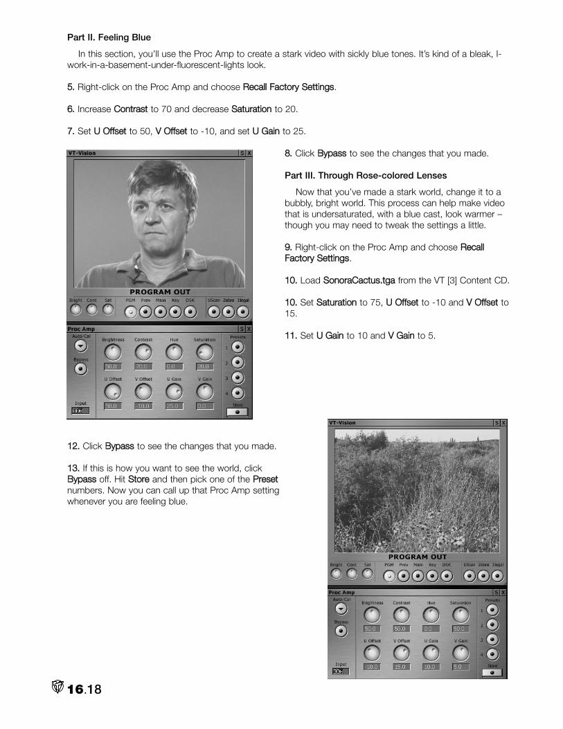
Part II. Feeling Blue
In this section, you’ll use the Proc Amp to create a stark video with sickly blue tones. It’s kind of a bleak, I-work-in-a-basement-under-fluorescent-lights look.
55.. Right-click on the Proc Amp and choose RReeccaallll FFaaccttoorryy SSeettttiinnggss.
66.. Increase CCoonnttrraasstt to 70 and decrease SSaattuurraattiioonn to 20.
77.. Set UU OOffffsseett to 50, VV OOffffsseett to -10, and set UU GGaaiinn to 25.
88.. Click BByyppaassss to see the changes that you made.
Part III. Through Rose-colored Lenses
Now that you’ve made a stark world, change it to abubbly, bright world. This process can help make videothat is undersaturated, with a blue cast, look warmer –though you may need to tweak the settings a little.
99.. Right-click on the Proc Amp and choose RReeccaallllFFaaccttoorryy SSeettttiinnggss.
1100.. Load SSoonnoorraaCCaaccttuuss..ttggaa from the VT [3] Content CD.
1100.. Set SSaattuurraattiioonn to 75, UU OOffffsseett to -10 and VV OOffffsseett to15.
1111.. Set UU GGaaiinn to 10 and VV GGaaiinn to 5.
1122.. Click BByyppaassss to see the changes that you made.
1133.. If this is how you want to see the world, clickBByyppaassss off. Hit SSttoorree and then pick one of the PPrreesseettnumbers. Now you can call up that Proc Amp settingwhenever you are feeling blue.
16.18

VIDEO 101:How to Read the Waveform Monitor
Video luminance is measured in amplitude, or volts; one volt peak-to-peak (1V p-p) is the nominal sig-nal for video. A perfect white signal is equal to one volt. This standard guarantees that signals from
different sources are compatible. Test signals, which are considered perfect signals, match the standard.Regular video does not contain any peak white levels and never measures 1V p-p.
You measure the video signal on the graph, or graticule, of the waveform monitor. The vertical axisshows amplitude, which is measured from 0 to 100 IRE units.
The IRE unit is a standard set by the Institute of Radio Engineers. An IRE is a relative unit of measurethat equals 1/140th of the peak-to-peak video amplitude.
Dark areas in the signal fall into the lower IRE units, while bright areas appear at the top of the graphwith higher IRE units.
The horizontal axis at 0 IRE measures time intervals in the video signal. Each tick mark along the axisindicates a division of time. Large ticks represent vertical blanking intervals and small ticks represent hori-zontal blanking intervals.
A video signal contains pulses with instructions for the electron beam of the monitor. The vertical blank-ing pulse tells the electron beam to shut off so it can travel to the top of the screen and begin the nextframe. The horizontal blanking pulse tells the beam to shut off so it can travel to the left and start the nextline. Blanking intervals represent the time that the beam is shut off.
For more information on blanking see the Blanking sidebar on page 16.21.
16.19

16.20
VIDEO 101:
How to Read the Vectorscope
Avectorscope display comprises the graticule and the trace. The graticule measures the video signaland the trace represents the color burst (see Blanking and Burst on the next page.)
The graticule is a full circle with tick marks in 2- and 10-degree increments. These marks represent theangle of a color, from 0 to 360 degrees. (Look at the Color Picker; the Hue values range from 0 to 360degrees.) The cross point in the center is the reference mark for centering the trace.
The circle is sliced into six wedges, each with small, graph targets. The targets are where each dot of acolor bars signal should fall if chroma gain and phase relationships are correct.
The chrominance signal can suffer distortions in amplitude (gain), and timing (phase) that cause obviouspicture problems. The waveform monitor measures amplitude. The vectorscope will reveal distorted phasewhere the color burst and target dots from a test signal do not align properly.

16.21
VIDEO 101:Blanking and Burst
Images on a television screen are created by an electron beam that scans across the back of the picturetube and causes the phosphor on the tube to glow. The beam sweeps across the tube 525 times
(NTSC) for each video frame, in a process called interlaced scanning. Odd lines are scanned in the firstpass, then the beam returns to the top to scan even lines.
The beam shuts off briefly when it moves from left to right, and this down time is called horizontalblanking. The beam also shuts off briefly when it moves from bottom to top, which is called vertical blank-ing.
Though the beam is shut off, the signal is not. During the blanking interval, synchronizing pulses (sync)and color reference (color burst) are sent. These bursts and pulses make sure the beam is in the rightplace at the right time, using the right color.
When the beam returns to the top of the screen, an equalizing pulse tells it which field the next scanrepresents, and a vertical syncing pulse verifies that the beam starts at the correct line.
When we talk about sync, we are referring to these phenomena of blanking and burst. You want yourequipment to be synced, that is to be on the same line in different videos at the same time, especially dur-ing live switching. If one camera is scanning line 500 and another is scanning line 120, you will see a visi-ble jump on screen when you switch between them. (However, VT [3] will sync all but the worst signals.)The same is true for color burst, you want the color reference for your inputs to match so that strangeshifts in color do not occur when you switch between sources.

Notes:
16.22

You can see a list of each panel’s Keyboard Shortcuts. Select the panel, right-click to open theContext Menu, and choose Keyboard Shortcuts.
General ShortcutsOpen with clear Desktop Shift + click on VT [3] icon
Toggle the Main Menu on/off ESC
Move between fields on a panel Tab
Toggle between the VT [3] and Alt + Tab
other open Windows programs
Copy Ctrl + c
Cut Ctrl + x
Paste Ctrl + v
Save Ctrl + s
Open or Load Ctrl + o
Open a new file Ctrl + n
Quit VT [3] Ctrl+ v + t
Delete Delete
Selection ShortcutsSelect all Ctrl + a
Select contiguous range of items Shift + click
Select non-contiguous group of items Ctrl + click
Select first item and deselect all others Home
Select all items from the last to the first Shift + Home
Appendix A.1
Appendix A: Keyboard Shortcuts

Select first item and keep current selection Ctrl + Home
Select last item and deselect all others End
Select all items from the last selected to the last Shift + End
Select last items and keep current selection Ctrl + End + Home
Deselect all items and select the previous one Left/Up Arrow
Select the previous contiguous items Shift + Left/Up Arrow
Select the previous non-contiguous items Ctrl + Left/Up Arrow
Deselect all items and select the previous one Right/Down Arrow
Select the previous items Shift + Right/Down Arrow
Select the previous items Ctrl + Right/Down Arrow
Deselect all Ctrl + Shift + A
VT [3] desktop shortcutsGo forwards through desktops Ctrl + Tab
Go backwards through desktops Ctrl + Shift + Tab
Go to Desktop 1 Ctrl + 1
Go to Desktop 2 Ctrl + 2
Go to Desktop 3 Ctrl + 3
Go to Desktop 4 Ctrl + 4
Go to Desktop 5 Ctrl + 5
Go to Desktop 6 Ctrl + 6
Filebin ShortcutsUp folder Backspace
Return to the folder that you just came from Shift+ Backspace
Fast forward preview at 10x speed Shift + rollover
Play preview backwards Alt + rollover
Play backwards at 10x speed Alt + Shift + rollover
Hotlist TAB
File Properties Ctrl + d
Appendix A.2

Character GeneratorGeneral Operations
Toggles Safe Area on and off Alt + s
Kerning on current character Alt + L/R Arrow
Toggles Page Lock on and off Shift + Ctrl + l
Selects entire line Shift + Up/Down Arrow
Selects one character Shift + L/R Arrow
Moves curser one word Ctrl + L/R Arrow
Selects one whole word Ctrl + Shift + L/R Arrow
Moves curser to beginning Ctrl + Home
Selects to the beginning Ctrl + Shift + Home
Selects to the end Ctrl + Shift + End
Deletes entire preceding word Ctrl + Backspace
Deletes entire trailing word Ctrl + Delete
Display Object Name Ctrl + Shift + D
Update Alt + z
Deselect Ctrl + d
Toggle VT-Vision on and off Ctrl + Shift + Tab
Toggle Program Out on and off Ctrl + Shift + Backspace
Mouse Operations
Multi-Select by area LMB + Drag
Multi-Select individual objects LMB + Ctrl
Multi-Select first to last selected LMB + Shift
Modify Tool
Move and Scale LMB
Rotate and Spacing Shift + LMB
Nudge 1 pixel Arrow keys
File Buttons
New CG Project Ctrl + n
Open CG Project Ctrl + o
Adds a page to the current CG Project Alt + Insert
Appendix A.3

Saves Project Ctrl + s
Saves Project As Shift + Ctrl + S
Saves Current Page Alt + Ctrl + S
Saves Current Page as Image Alt + Shift + S
Exit Ctrl + Shift + Q or Alt + F4
Modify Buttons
Selects Modify Tool Ctrl =
Selects Italic Tool Ctrl + 8
Selects Edge Tool Ctrl + 0
Selects Shadow Tool Ctrl + 9
Scroll Buttons
Activates GO Shift + Enter
Activates Cue Ctrl + Enter
Sets Motion Direction to UP Ctrl + PgUP
Sets Motion Direction to Down Ctrl + PgDWN
Sets Motion Direction to Left Ctrl + ,
Sets Motion Direction to Right Ctrl + .
Next Motion Behavior Alt + ,
Previous Motion Behavior Alt + .
Speed Preset 1 pixel/frame F1
Speed Preset 2 pixel/frame F2
Speed Preset 3 pixel/frame F3
Speed Preset 5 pixel/frame F4
Speed Preset 6 pixel/frame F5
Speed Preset 10 pixel/frame F6
Speed Preset 15 pixel/frame F7
Speed Preset 30 pixel/frame F8
Speed Preset 40 pixel/frame F9
Speed Preset 50 pixel/frame F10
Next Speed F11
Previous Speed F12
Appendix A.4

Increase Motion Speed by 1 Ctrl + F11
Decrease Motion Speed by 1 Ctrl + F12
Page Buttons
Go to Page Tab Ctrl + p
Adds a new page Ctrl + Insert
Deletes Current Page Shift + Delete
Clones Current Page Shift + Insert
Moves up the Page list PgUp
Moves down the Page list PgDwn
Tool Buttons
Selects Text Tool Ctrl + 1
Selects Text Left Alignment Alt + l
Selects Text Center Alignment Alt + c
Selects Text Right Alignment Alt + r
Selects Filled Box Tool Ctrl + 2
Selects Empty Box Tool Alt + 2
Selects Filled Polygon Tool Ctrl + 3
Selects Polygon Tool Alt + 3
Selects Polygon Line Tool Alt + Shift + 3
Selects Line Tool Ctrl + 4
Selects Filled Closed Spline Tool Ctrl + 5
Selects Closed Spline Tool Alt + 5
Selects Spline Tool Alt + Shift + 5
Selects Filled Circle Tool Ctrl + 6
Selects Empty Circle Tool Alt + 6
Selects Slice Tool Ctrl + Shift + 6
Selects Arc Tool Alt + Shift + 6
Selects Chord Tool Ctrl + Alt + 6
Selects Image Tool Ctrl + 7
Appendix A.5

Style Buttons
Adds current Style to Bin Alt + Shift + A
Removes current Style to Bin Alt + Delete
Layout Buttons
Select Layout Tab Ctrl + l
Align Left Alt + Shift + L
Align RightShift Alt + Shift + R
Align TopShift Alt + Shift + T
Align BottomShift Alt + Shift + B
Align HorizontalCenter Alt + Shift + C
Align VerticalCenter Alt + Shift + V
Arrange across Height Alt + Shift + H
Arrange across Width Alt + Shift + w
Divide Horizontal Ctrl + h
Divide Vertical Ctrl + v
Move to Top Layer Alt + Shift
Move to Bottom Layer Alt + Shift -
Move Up one Layer Alt =
Move Down one Layer Alt -
Group Selection together Ctrl + g
Ungroup Ctrl + u
Text Tab
Select Text Tab Ctrl + t
Increase Width by 5 pixels Ctrl + w
Decrease Width by 5 pixels Ctrl + Shift + W
Increase Height by 5 pixel Ctrl + h
Decrease Height by 5 pixel Ctrl + Shift + H
Increase Edge by 1 pixel Ctrl + k
Decrease Edge by 1 pixel Ctrl + Shift + K
Decrease Italic by 1 pixel Ctrl + i
Increase Italic by 1 pixel Ctrl + Shift + I
Appendix A.6

Increase Space by 1 pixel Ctrl + Space
Decrease Spacing by 1 pixel Ctrl + Shift + Space
Next Font Ctrl + f
Previous Font Ctrl + Shift + F
Next Text Direction Ctrl + Shift + T
Toggle Object Lock on and off Ctrl + Alt + l
Toggle Do Not Draw/Render on and off Ctrl + r
Edge Tab
Select Edge Tab Ctrl + b
Next Edge Type Alt + e
Previous Edge Type Alt + Shift + E
Next Edge Gradation Type Alt + g
Add 10 to Inside Edge Color: Blue Alt + [
Subtract 10 From Inside Edge Color: Blue Alt + n
Add 10 to Inside Edge Color: Green Ctrl + [
Subtract 10 From Inside Edge Color: Green Crtl + n
Add 10 to Inside Edge Color: Red Alt + Shift + [
Subtract 10 From Inside Edge Color: Red Alt + Shift + N
Add 10 to Inside Edge Alpha Alt + Ctrl + [
Subtract 10 From Inside Edge Alpha Alt + Ctrl + n
Add 10 to Outside Edge Color: Blue Alt + ]
Subtract 10 From Outside Edge Color: Blue Alt + m
Add 10 to Outside Edge Color: Green Ctrl + ]
Subtract 10 From Outside Edge Color: Green Ctrl + m
Add 10 to Outside Edge Color: Red Alt + Shift + ]
Subtract 10 From Outside Edge Color: Red Alt + Shift + M
Add 10 to Outside Edge Alpha Alt + Ctrl + ]
Subtract 10 From Outside Edge Alpha Alt + Ctrl + m
Shadow Tab
Select Shadow Tab Ctrl + /
Add 1 to Shadow Offset X Alt + x
Appendix A.7

Subtract 1 to Shadow Offset X Alt + Shift + X
Add 1 to Shadow Offset y Alt + y
Subtract 1 to Shadow Offset y Alt + Shift + Y
Add 5 to Shadow Softness Alt + Shift + ;
Subtract 5 to Shadow Softness Alt + Shift + '
Add 10 to Shadow Color: Blue Ctrl + Shift + B
Subtract 10 to Shadow Color: Blue Ctrl + Alt + b
Add 10 to Shadow Color: Green Ctrl + Shift + G
Subtract 10 to Shadow Color: Green Ctrl + Alt + g
Add 10 to Shadow Color: Red Ctrl + Shift + R
Subtract 10 to Shadow Color: Red Ctrl + Alt + r
Add 10 to Shadow Alpha Ctrl + Shift + A
Subtract 10 to Shadow Alpha Ctrl + Alt + a
Next Shadow Type Ctrl + Alt + s
Arc/Line Tab
Select Arc/Line Tab Ctrl + j
Add 1 to Thickness Alt + ;
Subtract 1 from Thickness Alt + '
Add 5 to Arc Radius Alt + \
Subtract 5 from Arc Radius Ctrl + \
Next End Style Ctrl + e
Next Joint Style Alt+ j
Fill Tab
Select fill Tab Alt + f
Rotate Fill +15.0 Degrees Alt + a
Next Fill Range Alt + t
Next Fill Type Ctrl + \
Cycles thru Preset Gradients Alt + d
Cycles Thru Recent Images Alt + i
Appendix A.8

Print To TapeIf Tape Stopped
Rewind j
Play k
Otherwise
Reverse Shuttle j
Pause/Play k
Forward Shuttle l
Also
Stop Shift + K
Record Ctrl + Shift + K
One Frame Back Alt + j
One Frame Forward Alt + l
Go to Time position Ctrl + g
Mark In Point i
Mark Out Point o
CaptureRecord/Stop Enter
Pause toggle Spacebar
Reset (Clear) recording Delete (when recording)
Chop recording Backspace
SwitcherProgram inputs 1-10 F1 - F10
Program inputs 11-20 Shift + F1 - F10
Program inputs 21, 22 F11-F12
Program inputs 21, 22 Shift + F11-F12
Preview inputs 1-10 1 - 10
Preview inputs 11-20 Shift + 1 - 10
Preview inputs 21, 22 -, =
Preview inputs 23, 24 Shift + -, =.
Appendix A.9

Key inputs 1-10 Alt + 1 - 0
Key inputs 11-20 Shift + Alt + 1 - 0
Key inputs 21, 22 Alt + -,=
Key inputs 23, 24 Shift + Alt + -.=.
Preview previous input , (comma, <)
Preview next input . (period. >)
Preview to Black b
Preview to DDR1 n
Preview to DDR2 m
Auto to Black Shift + B
Auto to DDR1 Shift + N
Auto to DDR2 Shift + M
Lockkey (on/off) q
Repeat (on/off) w
Reverse (on/off) e
Advance DVEs (on/off) r
T-Bar / Take.
Take Return
Jump T-Bar back to top Shift + Return
Auto, Go/Stop Spacebar
Reverse Auto Shift + Spacebar
Take Halfway T-Bar h
Toggle LockKey on/off q
Toggle Reverse on/off w
Auto Halfway T-Bar Shift + G
Slow, Medium, Fast z, x, c
Slightly Slower Speeds Shift + Z, X, C
Much Faster Speeds , . /
Use Variable speed v
Set Variable speed Shift + V
Appendix A.10

Downstream Key (DSK)
Autofade DSK && T-Bar a
Switch DSK on/off & Take s
DSK on/off d
Fade DSK on/off f
DVEs
Go to Crossfade effect TAB
Shift + TAB Go back to DVE effect
Left Arrow Previous DVE
Right Arrow Next DVE
For Special Shortcuts and Patched Shortcuts, right-click on the Switcher Panel.
VT-EditTimebar
Set current Edit Line Click (on Timebar)
Set current Edit Line Shift + click (on empty area of Timeline)
Pan Timebar and project Right-click + drag left or right
Expand Timebar horizontally Right-click + drag up or down
Drag and Drop
Clone Ctrl + Drag
Inherit Drop item + Alt
Skip AutoFade (Timeline) Drop item + Shift
Storyboard Drag and Drop
Preview In and Out points Alt + rollover
Change In/Out points Alt + drag
Change In/Out points, audio only Ctrl + Alt + drag
Slip and slide Shift + Alt + drag:
Slip and slide; audio only Shift + Ctrl + Alt + drag
Timeline Drag and Drop
Constrain to vertical dragging only v
Change In and Out points Drag Crouton edge
Preview In and Out points Alt + rollover
Appendix A.11

Stretch (speed) Alt + drag edge
Slip and Slide Shift + Alt + drag
Change length of DVE Drag DVE edge
Change In and Out points of DVE Shift + drag DVE edge
Slip and Slide DVE Shift + Alt + drag DVE
View
Show Keyboard Shortcut list F1
Maximize Active view F2
Storyboard / Files view F3
Storyboard / Timeline view F4
Timeline / Files view F5
Timeline / Timeline view F6
Files / Files view F7
Edit Properties panel F8
ToolShed panel F9
Window
Add Ctrl + i
Play
Play/Stop Spacebar or k
Preroll and Play Shift + Spacebar
Stop/Go to start Ctrl + k
Step through clips Up / Down arrows
Step through clips and zoom (Timeline) Shift + Up / Down arrows
Go to Start of project Home
Go to End of project End
Go to Time position Ctrl + g
Jog
One Frame Back Left Arrow, 1 or Alt + j
One Frame Forward Right Arrow, 2 or Alt + l
Five Frames Back Shift + Left Arrow, or 3
Five Frames Forward Shift + Right Arrow, or 4
Appendix A.12

One Second Back Ctrl + Left Arrow
One Second Forward Ctrl + Right Arrow
Shuttle
Backwards j
Forwards l
Rewind Shift + j
Fast Forward Shift + l
Misc
Track On/Off u
Loop On/Off '
LED Normal/Time Remaining ;
LED Local/Total Time Shift + ;
In/Out Points
Note: if no clips are selected, these use nearest clip to current time.
Mark
Mark In Point i or e
Mark Out Point o or r
Mark In then review Shift + I
Mark Out then review Shift + O
Place Temp Out marker p
Use Last Temp marker as Out Point Shift + P
Clear
Clear In Point d, Alt + i
Clear Out Point f, Alt + o
Clear Both In and Out Points g, Alt + p
Go to
Go to In Point q
Go to Out Point w
Preroll before In and play Shift + Q
Preroll before Out and play Shift + W
Adjust In point q + Left/Right Arrow
Adjust Out Point w + Left/Right Arrow
Appendix A.13

Offset (Clip start time)
Adjust Offset (-/+ 1 frame) Alt + Left/Right Arrow
Overlay
Toggle Overlay on and off y
Special Tools
Fades, Insert Range Alt + f
Spline EditorActive Curve only
Add node n
Add influence m
Previous / Next node , and . (< > keys)
Go to first node Home
Go to last node End
Select all Ctrl a
Select all nodes before scrub bar Shift Home
Select all nodes after scrub bar Shift End
All Curves
Add node Alt n
Add influence Alt m
Previous / Next node Alt , and . (< > keys)
Go to first node Alt Home
Go to last node Alt End
Select all Alt Ctrl a
Select all nodes before scrub bar Alt Shift Home
Select all nodes after scrub bar Alt Shift End
Clipboard
Cut node Ctrl x
Copy node Ctrl c
Paste node Ctrl v
Appendix A.14

Paste node at scrub bar Ctrl Shift v
Delete node Delete
Convert selected nodes to influences /
Convert selected influences to nodes Shift /
Zoom
Fit BackSlash
Zoom out / Zoom in - and =
TimelineCut
Cut (Razor) at time bar c
Cut to selected clip (Multicam) z
Markers
Add Marker m
Previous / Next Marker , / . (< > keys)
Ripple
Enable Timeline Ripple t
Disable Timeline Ripple Shift + t
Scroll
Center display around time bar BackSpace
Scroll Left / Right [ and ]
Scroll Half Left / Right Shift + [ and ]
Scroll to Start / End of Project Ctrl + [ and ]
Constrain to vertical dragging only v
Timebar
Set current time marker Shift + Click
Pan through project Right Click + Drag Left/right
Zoom in/out of project Right Click + Drag up/Down
Slowly pan or zoom project Ctrl + Right Click + Drag
Appendix A.15
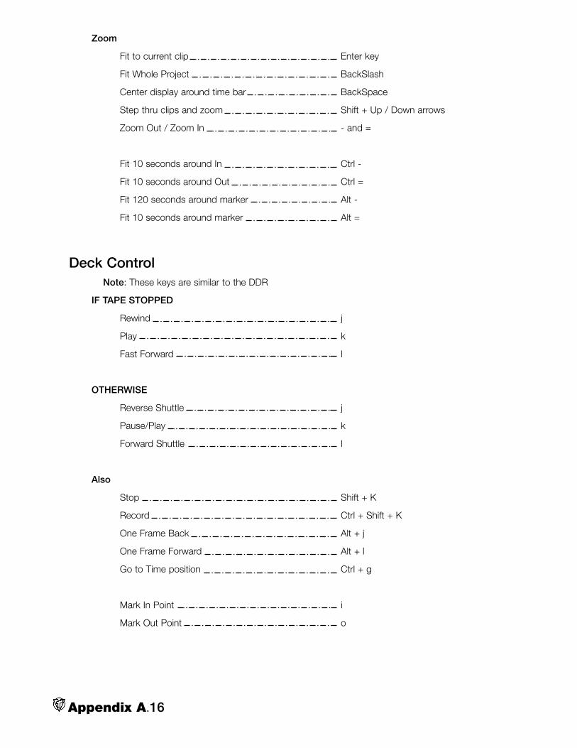
Zoom
Fit to current clip Enter key
Fit Whole Project BackSlash
Center display around time bar BackSpace
Step thru clips and zoom Shift + Up / Down arrows
Zoom Out / Zoom In - and =
Fit 10 seconds around In Ctrl -
Fit 10 seconds around Out Ctrl =
Fit 120 seconds around marker Alt -
Fit 10 seconds around marker Alt =
Deck ControlNote: These keys are similar to the DDR
IF TAPE STOPPED
Rewind j
Play k
Fast Forward l
OTHERWISE
Reverse Shuttle j
Pause/Play k
Forward Shuttle l
Also
Stop Shift + K
Record Ctrl + Shift + K
One Frame Back Alt + j
One Frame Forward Alt + l
Go to Time position Ctrl + g
Mark In Point i
Mark Out Point o
Appendix A.16

DDRPlayback
Play/Stop k
Preroll and Play Alt + k
Pause Shift + k
Stop/Go to start Ctrl + k
Step through clips Up / Down arrows
Go to Start Home
Go to End End
Go to Time position Ctrl + g
Jog
One Frame Back Left Arrow, or Alt + j
One Frame Forward Right Arrow, or Alt + l
Five Frames Back Shift + Left Arrow
Five Frames Forward Shift + Right Arrow
One Second Back Ctrl + Left Arrow
One Second Forward Ctrl + Right Arrow
Shuttle
Backwards j
Forwards l
Rewind Shift + j
Fast Forward Shift + l
Misc
Cue on/Off u
Loop On/Off '
LED Normal/Time Remaining ;
LED Local/Total Time Shift + ;
In/Out Points
Note: These use nearest clip to current time.
For selected clip control, set DDR Playlist to Selection mode.
Mark In Point i
Mark Out Point o
Appendix A.17

Place Temp Out marker p
Use Last Temp marker as Out Point Shift + P
Clear In Point Alt + i
Clear Out Point Alt + o
Clear Both In and Out Points Alt + p
Go to In Point [
Go to Out Point ]
Adjust In point [ + Left/Right Arrow
Adjust Out Point ] + Left/Right Arrow
Batch CaptureNote: These keys are similar to the DDR
Also
Stop Shift + K
Record Ctrl + Shift + K
One Frame Back Alt + j
One Frame Forward Alt + l
Go to Time position Ctrl + g
Mark In Point i
Mark Out Point o
Capture Mark In/Out
Mark In/Out Advance Spacebar
Mark In i
Mark Out o
End Text Entry Esc
Appendix A.18

VT [3] AND THE WEB
With more consumers accessing the Internet through high bandwidth connections, video has becomeviable content on the Web. Now you can send your own video from VT [3] to the Internet through a third-
party encoder.
VT [3] comes packaged with Windows Media Encoder, but you can use any encoders that accept Video forWindows devices as a source. The most widespread formats available are Real G2 for the Real Player, and theQuickTime format.
On the Web, you have two options for viewing video. One option is a file that you download to your harddrive and then play on your computer with the associated video player. The other option is streaming video,where you click on a link and the associated player launches and begins to load the file. As the file is buffered, itbegins to play, so you don’t need to wait for the whole file to download before you can watch it.
EncodingEncoding a video file means that you compress the file into a specific format. When you use a progressive
format, you save the file and users must download the entire file before they can view it. This is considered anon-demand file because it’s available to users at any time. When you use a streaming format, users downloadonly the beginning of the file and they can view it while the file is buffered. In real-time streaming, the videospins off of a server and viewers can immediately watch it on their desktops.
To encode a file, you launch your encoder and follow the instructions in the wizard. Usually, you just chooseyour source file, enter a name for the destination file, choose your audio and video codecs, choose a bit rate,and hit Start. The encoder compresses the file and then you upload that file to your Web site.
Downloadable Files
The advantage of downloadable files is that the quality is pre-determined. Changes in line speed may delaythe download but they won’t cause fluctuations in frame rate, audio dropout, etc.
The following formats are typical for downloadable files:
• AVI is the video file for Windows.
• MOV is the QuickTime format, which works on Mac and Windows.
• MPEG works on all platforms and operating systems.
Appendix B.1
Appendix B: Streaming Media

Streaming Video
The advantage of streaming video is that users avoid the long wait, so they can view the video while it down-loads. This is a big advantage, especially with videos that would take hours to download entirely. But the disad-vantage is that quality can suffer; the quality depends on the data transmission channel. Some streaming soft-ware adjusts itself to the data rate as it plays, dropping as many frames as it has to in order to keep playing.Real-time streaming video tries to keep pace with the user’s connection speed in so that you don’t havedropped frames or pauses in the video.
Longer videos are most appropriate for streaming, where users can skip ahead to other parts of the clip anddon’t have to download a huge video file. Users cannot download streaming content to their hard drives;streaming video clips sit on the server until you remove them.
The following formats are typical for streaming files:
• ASF, WMV, and WMA are the Windows Media formats.
• MOV is the QuickTime format, which works on Mac and Windows.
• Rm is the format for Real, which works on all platforms.
Live Encoding
Live encoding takes a little more work than encoding a file; the source going to the encoder comes from audioand video capture cards on your computer. Before you encode you should consider the following variables:
• What format will you use: Windows Media, QuickTime or Real?
• What data rate, frame rate, window size? These variables affect the final size of the file and its quality.
• Progressive download or real-time streaming?
Streaming and VT [3]Before you can begin encoding for streaming, you must first install the encoder. For our purposes, we refer
to the Windows Media Encoder. Information for installing Windows Media Encoder is available in the help file inthe Windows Media directory, but all you need to do is click on the install file. Other encoders will provide infor-mation about installation and settings in their documentation.
The VTCap plug-in is the key to creating live streaming video from VT [3]. It is automatically installed whenyou install the VT [3] software. The VTCap plug-in monitors your video sources and communicates informationto the encoder. So, while you switch between your sources on the switcher, the plug-in monitors VT [3] andsends the info to Windows Media Encoder. So all you need to do is choose your settings in the encoder andget to work.
In Windows Media Encoder, you choose custom settings to specify a live source. You then set the bit rate forthe stream that you are encoding. You can set a multiple bit rate, where you encode different bit rates in one fileso that users with different connections can see the stream, or you can encode a single rate for the file. The fol-lowing steps are basic steps for setting up your encoder. For more information on specific settings, see thedocumentation for Windows Media encoder.
WWAARRNNIINNGG
When you work with Windows Media encoder, your files must be saved with audio. The encoder will notencode files without embedded audio.
WWAARRNNIINNGG
You must have a sound card installed on your computer to work with Windows Media Encoder. The VT[3] card will appear as your audio card when you choose your settings. You must choose the VT [3] cardas your video and audio card.
Appendix B.2

Windows Media Encoder and Streaming Live Video from VT [3]
11.. Open Windows Media Encoder. On the Start menu, point to Programs, point to Windows Media,and then click Windows Media Encoder.
22.. In the Welcome window, select Custom settings. If the Welcome window does not appear whenWindows Media Encoder opens, on the File menu, click New.
33.. On the Input Source screen, select Live source.
44.. On the Capture Source screen, use the default settings.
55.. On the first Bandwidth Selection screen, select UUssee mmuullttiippllee bbiitt rraattee video.
66.. On the second Bandwidth Selection screen, select LLooww BBaannddwwiiddtthh or HHiigghh BBaannddwwiiddtthh. Theencoded live stream will contain multiple streams encoded at the bit rates shown in the lower list.You can Add, Remove, or Edit bit rates in the list, or accept the default settings.
77.. On the Compression and Formats screen, select audio and video compression codecs for thebandwidth you are targeting. If you are encoding multiple bit rates, choose a video codec suitable forthe highest bandwidth, and an audio codec suitable for the lowest bandwidth.
NNOOTTEE
VT [3] is Windows Media certified; our capture card is certified to work with Windows Media software.
After you choose your settings, you can launch the encoder at any time from VT [3] by clicking the OOnn AAiirrSSttrreeaamm button at the right of the main menu or if you open the menu on the left, it’s at the top left.
Getting Your Video on the WebIf you are using an on-demand format, you can encode your video and FTP it to your web site or a media
server. You can make a link to your video exactly as you do with a graphic or other file: <ahref=”myVideo.avi”>Watch a video</A>
Your viewers must have the players installed for the type of format you use, so if you use Windows Media,they must have Windows Media Player, if you use QuickTime, they need the QuickTime player, and so on. Youmay want to include a link to download the player.
If you plan to distribute streaming video, you need a video server. The Windows Media and the QuickTimeservers are both free. Apple’s QuickTime Streaming Server uses RTSP, which is an open standard that is avail-able for servers ranging from UNIX to NT. Real server starts at about $295 for the software. With Real, you alsomust pay for traffic to your stream: the more people view your video, the more it costs you.
VT [3] is bundled with Microsoft Windows Media. Windows Media is a common format for streaming video.The Windows Media Server runs a proprietary server protocol, but it’s free and it works on Windows ServerPlatforms. The Windows 2000 Server and the Advanced Server come packaged with the Windows MediaServer as part of the operating system. A panel appears when you install that takes you through the process ofsetting up the server step-by-step.
Note that when you use a live broadcast, you can upload streaming media to your Web site without a videoserver. Up to 50 people can connect to your computer to watch streaming video without the server, if you areattached via a constant, broadband connection. If more than 50 visitors will access your files, you will need abroadband distribution point, that is, a video server.
Appendix B.3
The On Air Stream button is in between the Padlock icon and the Minimize button

Getting Your Files on the ServerOnce you create and encode your streaming media and build the Web page for the media player and related
data, you must post your files on the appropriate Web servers. The process for setting up a streaming mediaserver is more complex than setting up the encoder, and you need to contact your Internet Service Provider(ISP) for specific details. If you run your own server, and you can get information about installing a media serverfrom the documentation that comes with the server software. However the following list contains the informationthat you need to get when you’re working with an ISP:
• a log-on identification number and password for the Internet servers where you will post your HTMLpages and media
• the address for the HTML server where the layout and redirector files will be stored on the Web server;this is the directory path that you use to transfer files with a file transfer protocol (FTP) program
• the address for the video server where the streaming media will be stored; this is the directory path thatyou use to transfer the file with an FTP program
Before you upload your files, you must create a redirector file. As you may have noticed from the previouslist, you use two servers to get your streaming video on the Web—one for HTML pages, and the other forstreaming media. A user requests streaming media from the HTML server, and a redirector file on the HTMLserver redirects the request to the media server. This file is usually placed in the same folder as the HTML page.For examples of redirector files visit www.msdn.microsoft.com and enter “asx” in the search function.
Preparing for EncodingBefore you create video for the Web, whether it is streaming video or downloadable video, you need to make
some preparations first. Of course, you should have an idea of how your final video will be assembled and youshould have those elements—video, audio, graphics, effects and so on—ready before you start.
Audience for Web Video
Your audience is the critical element when you create video for the Web. Your preparations and your finaloutput will differ depending on whether you want a wide audience, which includes users with slow connections,or if you are willing to limit your audience to those with high bandwidth connections, and offer higher qualityoutput.
Video Capture for the Web
When you capture video for Web distribution, the best approach to ensure decent quality is usually to cap-ture it at the size that you will use for final output. When video is compressed, as it must be for the Web, youlose lots of detail, and to compress a full-screen video down to a quarter or a sixteenth of its size is a lesson inhumility. However, you still want to work with the highest resolution possible, so that you give good informationfor encoding.
However, when you work with VT [3], you should capture your video at full resolution. Then, when you acti-vate the encoder, choose your compression settings to suit your intended audience.
Audio Capture for the Web
You capture audio at the same time that you capture video. You want your audio to be CD quality, so itshould be sampled at 44.1 KHz and 16 bits. The audio will be compressed as well, but again, you want to startoff with the best quality possible.
Other Variables for Web Video
Other variables to keep in mind when you’re creating video for the Web are contrast and motion. Videodoesn’t handle contrast as well as film, and when you encode video for the Web, you lose even more informa-tion, so you need good lighting in your source video.
Web streaming doesn’t handle transitions and motion well and it doesn’t capture detail so your best shotsshould be close and without a lot of movement. Audio from cameras and camcorders is rarely as good as sep-arate microphones, you should at least use a lavaliere microphone and/or a directional or shotgun microphoneso you hear only what you want.
In streaming video, you can give your viewers some control over the video—they can skip ahead to informa-tion, for example. You must encode metadata into your file, choose the right delivery platforms, and code HTML
Appendix B.4

pages to provide access. Metadata can also be used to encode information such as author, copyright, rating,and a description of the video. This information can be displayed in the media player as the content isstreamed.
One of the most useful functions of metadata is that you can use it to run commands that will open a Webpage or launch a Java application. You can synchronize these events to specific times and events in thestreaming content. For instance, as the streaming audio describes a product, metadata could launch thebrowser and open a related Web page. Instructions on how to encode metadata are included in the documen-tation for your encoding software.
Tips for Video on the WebThese tips refer to creating video for a wide range of users, they are meant as guideline for creating video
that is accessible to low bandwidth users specifically. When you create video for users with fast connections,these issues are less of a concern, but are still good guidelines.
Picture Size
Depending on your audience, your picture size may need to be very small. Typical web-based videos use ahalf or a quarter of a screen; when you use the VT [3] encoder, the lowest resolution available is 360 x 240.
Frame Rate
U.S. television (NTSC) delivers video at 29.97 frames per second (fps). The rate for European television (PAL)is 25 fps. Most computer video cuts the frame rate to 15 or 10 fps. If you expect your users to work on veryslow connections, you should reduce frame rate down to five or six frames per second. However, the framerate should always be a number that divides evenly into 30 fps (for NTSC) or 25 fps (for PAL).
Limit Your Palette and Use Bright Colors
Much like web graphics, web video looks best when you use bright and solid colors. Dark colors and pat-terns may not translate well over slow connections. 8-bit color (256 color palette) gives your video the best lookfor the widest range of viewers.
Reduce Motion
Fast motion and transition also do not translate well across slow connections; this also applies to specialeffects because they usually require motion and subtle colors.
Appendix B.5

Notes:
Appendix B.6
DVE ORGANIZATION AND CONVENTIONS
Two beasts dwell in the world of Digital Video Effects (DVEs): the *.DVE file and its clone the *.DVR file. (Don’tworry; no sheep were harmed in their development.) The DVE file is the actual effects file, and the DVR file is
just a text file that points to a DVE file.
The DVR file tells the software to run the original in reverse. Not all DVE files have an associated DVR file. SomeDVEs just don’t make sense in reverse (though you can make any DVE run in reverse choosing Reverse on theswitcher). Some DVEs already have reverse versions. Also, Billy needs something to do for Video Toaster 3.
OK, so you’re asking, “Why have a DVR file if the switcher already has a Reverse button?” Well! EDL, silly.Edit Decision Lists use a four-digit code to reference effects used in a video project.
To prepare Video Toaster for importing and exporting EDLs, we assigned four-digit codes to all DVEs. Apointer file lets us do this without physically creating more DVEs, which would take up more hard drive spaceand months of rendering time.
We also added the codes to introduce the DVE QuickCall. With QuickCall, you can type a four-digit code intothe numeric keypad to load a DVE. You will no longer need to scan through directories to find the DVE youwant.
The naming conventions for the DVE files are the same for both DVE and DVR files. As we know, every DVx(DVE or DVR) file has a four-digit numeric code assigned to it. We incorporated this code into the DVE file nameto help you learn and associate them. The four-digit code is followed by a hyphen and a five to seven charactername, and then the file extension; it looks something like this: ####_FILENM.DVE. You get a lot of informationfrom this name despite its short nature. From this name, you can find a file in its directory, subdirectory, and tellwhich direction the effect travels in.
The Numeric Codes:####_FILENM.DVE
The first four digits in the file name tell you where it’s located and in what direction it plays.(#)###_FILENM.DVE: The first digit tells you the main directory an effect falls into. These directories are
installed wherever you installed your DVEs. So, if your video drive is volume V: you probably store your DVEsthere.
You can distinguish the main directories for the DVEs because their codes are a digit followed by three zeros.Only ten directories, or categories, exist for DVEs. But have no fear; there are always subdirectories. The Main(and Sub) Categories and directories are listed below:
Appendix C.1
Appendix C: DVE Descriptions
Developed by Billy Pecora

1000_Wipes:
1000_WipesWipes are traditional and non-traditional effects. The video (usually the entire screen of Video) moves along
one or two axes that are parallel to the monitor screen.
1100_ShapesShapes are wipes that happen as shapes. The video wipes onto the screen from the center in a shape such
as a circle, diamond, oval, star, and so on.
1200_BlindsBlinds are wipes that happen in sections. The video screen is broken up into several bands while it moves.
Currently Video Toaster has Blinds that happen only in sets of 4, 6, and 8. Some systems place Blinds in theirown category; we have divided them between Wipes and Rotations, which better describe their movement.
1300_PushsPushs refer to PushPulls. YES! YES! We know that traditionally PushPulls have their own category, but in a
very real sense a PushPull is closely related to a wipe. In a PushPull, video wipes onto the screen and PUSHESthe other video off. We knew you’d agree.
2000_Curls:
2000_CurlsCurls are also known as Page Curls. One corner of the video screen or edge of the video screen bends up
and over the rest of the screen and leads the rest of the video off the screen.
2100_WarpsWarps are effects that distort the video. Warps are any effect used on the video in which the video does not
remain flat as the effect plays.
3000_Trajs:
Trajs refer to Trajectories. Currently, there are no sub directories or categories for Trajs. Typically, Trajectoriesdo not follow any singular motion path or are open to move along any axis or angle.
4000_Fades
Fades are any effect where the first source of video dissolves into the second.
5000_Olays
Olay refers to Overlays. An Overlay is any effect that sits on top of a video picture.
5000_OlaysAn Overlay is any effect that sits on top of a video picture and does not change the underlying video in any
way. In most cases an Overlay is a looping animation or a stationary graphic.
5100_CrmaEChroma Effects are similar to Overlays. Chroma Effects sit on top of a video picture, but they also do wacky
things with the Chroma of the video. Color cycling of live video anyone?
6000_Rotas
Rotas refer to Rotations.
6000_RotasRotations are effects that rotate around the edge of the video screen either perpendicular or parallel to it.
6100_SpinsSpins are effects that rotate around an axis anywhere within the video plane.
Appendix C.2

6200_BlindsBlinds are all Rotations and Spins that happen in sections. The video screen is broken up into several bands
while moving. Currently Blinds work only in sets of 4, 6, and 8. Some systems place Blinds in their own catego-ry; we have divided them between Wipes and Rotations, which better describe their movement.
7000_Miscs
Miscs is for Miscellaneous effects. This could have been called Special but all of our DVEs are special, andwe wouldn’t want any of them to feel bad because they’re not in the special class.
7000_MiscsMiscellaneous is the subdirectory where all effects that don’t really fit in any other category come to live.
7100_OrgncOrganics are wipes that are not easily described but typically have a very natural organic look and feel.
Generally, they have soft edges or are natural-looking phenomena.
7300_PeoplPeople contains effects that use real video footage of people and animals in different activities.
8000_Comprs:
Comprs are Compresses.
8000_ComprsIn Compresses, the video is generally shrunk or expanded.
8100_P-in-PPicture in Pictures effects are over-the-shoulder shots, which are effects that place a window of video on top
of another as you see on news broadcasts.
9000_Bordrs
Borders are very similar to Wipes in most respects. Borders, however, have some sort of border at the edgeof the wipe.
0000_Expan
Expansion is a category that has been left open for third party development; Expansion room to grow into,and for Studios to use for their own custom-created DVEs once the DVE Creation Kit is released for public con-sumption.
These are the Main directories/categories of DVEs and their sub-directories/categories. The sub-directoriesand categories help you find effects when you look for them through the File Bin.
A DVE file name begins with its main directory. Let’s use a Wipe as an example: All wipes will have a file name that begins with 1###_, should the wipe also be a shape wipe it would then
begin with 11##_. So by looking at only the first two digits of the DVE file name you will know its location in thesystem. (Assuming you know which drive all the effects have been installed too.)
#(##)#_FILENM.DVEThe second and third digits in the DVE code act as the individual DVEs identifier.
As stated before the second digit sets the subcategories or subdirectory while the third is unique to that DVEin that subgroup. In instances where there are no subcategories or subdirectories these two digits act togetheras the ID. So to continue our example with the wipe, we would now have 101#_, which places us in the wipesand in the first group.
###(#)_FILENM.DVEOK, we’ve discussed the first three digits of the code. So, what’s that last digit for if we already have
the DVE categorized, sub-categorized, and identified? Well, it tells us the direction the effect moves in. Look at
Appendix C.3

the numeric keypad on your keyboard, and you see four arrows printed on certain keys already. We simply fill inthe other keys and we have our directions and in some cases (like with overlays) positions, as shown in ImageD1 below.
If we go back to our wipe example, we see that thefourth digit tells us the direction the wipe shouldtravel in. 1014_ is in the first group of wipes, and itis the wipe that moves from right to left. If thiswere an Overlay of a rotating globe, for example,the globe would show up centered on the left sideof the screen. The numbers can also refer to oppo-sites. For example, 1 is the opposite direction of 9,and in some categories of effects where this makessense it has been employed.
####_(FILENM).DVEA five to seven character name is also incor-
porated into the file name so you can recognize aneffect more easily without knowing the four-digitprefix. Granted, a short name is not very descrip-tive. But these names are meant to be used withthe prefix, not on their own. Essentially, this part ofthe name gives information about the DVE that isnot easily assigned to a numeric code. The groundwork is being laid now to make DVE selection easi-er, admittedly it may seem this is not the casenow…but, OH, just you wait.
The character name distinguishes differentgroups or sets of DVEs from others within thesame subcategory. For example, you may havenoticed that a DVE can travel in one of ten direc-
tions, so in theory there should be only ten wipes. Well, the magical land of the Video Toaster offers 17 DVEs inthe subcategory of wipes. Eight of these wipes are the different directions of the ordinary wipe where the fullscreen of video slides in one direction to reveal new video behind it (the 103# DVEs). However, a closely relatedgroup of wipes does the same thing, but instead of the entire video image moving off screen at once, it willremain in place as the screen slides to reveal video underneath. The video itself does not move, only the edgebetween sources moves (the 104# DVEs). To distinguish between these two STYLES of wipes we call the firstWipe and the second Wipe2. So, our DVE file names end up being 103#_Wipe.DVE and 104#_Wipe2.DVErespectively.
The following list defines all of the main Character name conventions, which are found throughout the DVEs.In some instances the following conventions may be the only characters in the name.
STA > > > A stationary effect; in most cases this applies only to Overlays.
H, Hz or Horz > > > Horizontal Segments of Video
V, Vt, or Vert > > > Vertical Segments of Video
CCW > > > Counterclockwise movement; usually associated with Rotations or Spins
CW > > > Clockwise movement; usually associated with Rotations or Spins
Seq > > > Sequential movement; usually associated with wipe blinds
Opp > > > Opposite movement; usually associated with the motion of alternating blinds
Appendix C.4
IImmaaggee DD11.. DVE positions and the numeric keypad

As with all conventions, rules, guidelines, and laws, some cases will not always follow. You should consultthe DVE descriptions for clarity. The descriptions are arranged according to the main categories. The DVEicons are also animated to let you preview an effect. The icons are AVIs and can be played from outside theVideo Toaster environment. The icons share the exact same name as their corresponding DVE.
TOASTER DIGITAL VIDEO EFFECTS DESCRIPTIONS
Group: 1000_Wipes \ 1000_WipesDVE: 101#_Trap
Directions: Top (1018)Positions: Bottom (1012)
Description: Video Source ‘A’ is covered by Source ‘B’. Source ‘B’starts off screen from either the top or bottom, a left or right sidepanel slides up into view hinging around either center top or centerbottom. The movement resembles a bear trap closing. (This DVEcould be considered or better placed in the Rotas Category.)
DVE: 102#_Checker
Directions: Left (1024)Positions: Both Left and Right (1025)
Right (1026)
Description: The video is cut up into a CheckerBoard pattern where one set of squares wipes offin the selected direction followed by the remainingset. If you looked at a chessboard, the white squares would wipe to the left and then the black squares wouldwipe to the left. In 1025_Checker, each square squeezes to its vertical centerline but still follows the same pat-tern of white then black. The video is not tinted with alternating black and white squares.
DVE: 103#_Wipe
Directions: To the Top Left (1037)Positions: To the Top (1038)
To the Top Right (1039)To the Left (1034)To the Right (1036)To the Bottom Left (1031)To the Bottom (1032)To the Bottom Right (1033)
Description: The video slides across the screen either concealing orrevealing the background video. The moving video moves as a singleplane.
Appendix C.5

DVE: 104#_Wipe2
Directions: To the Top Left (1047)Positions: To the Top (1048)
To the Top Right (1049)To the Left (run 1046 in
reverse)To the Right (1046)To the Bottom Left (1041)To the Bottom (1042)To the Bottom Right (1043)
Description: The video slides across the screeneither concealing or revealing the backgroundvideo. The video (both background and fore-ground) is locked into place, the wipe happens asan edge travels across the screen.
1000_Wipes \ 1100_ShapesDVE: 110#_Circle
Directions:Positions: Center In (1105)
Description: The video wipes on and off the screen from the center in the shape of acircle.
DVE: 111#_Oval
Directions:Positions: Center In (1115)
Description: The video wipes on and off the screen from the center in the shape ofan oval.
DVE: 112#_Diamnd
Directions:Positions: Center In (1125)
Description: The video wipes on and off the screen from the center in the shape of adiamond.
Group: 1000_Wipes >> 1200_BlindsDVE: 120#_Curt6
Directions: To Top Left and Right Corners (1206)
Positions:
Description: The video is split up into six ( _Curt6 ) vertical bars. The bars start fromthe center and move up toward the left and right corners. The result is similar to astage curtain being opened.
Appendix C.6

DVE: 120#_Curt8
Directions: To Top Left and Right Corners (1208)
Positions:
Description: The video is split up into eight ( _Curt8 ) vertical bars. The bars start fromthe center and move up toward the left and right corners. The result is similar to astage curtain being opened.
DVE: 121#_H4Opp
Directions/Positions: Center to Left and
Right (1215)
Description: The video is split into four horizontal bars ( _H4Opp ) that slide horizon-tally in alternated pairs.
DVE: 121#_H4Seq
Directions/ To the Bottom (1212)Positions:
Description: The video is split into four horizontal bars ( _H4Seq ) that slide verticallyone after the other in the direction they are moving.
DVE: 121#_H4Seq
Directions: To the Left (1217)Positions: To the Right (1219)
Description: The video is split into four horizontal bars ( _H4Seq ) thatslide horizontally one after the other starting with the top most bar.
DVE: 122#_H6Opp
Directions:Positions: Center to Left and
Right (1225)
Description: The video is split into six horizontal bars ( _H6Opp ) that slide horizontallyin alternating pairs.
DVE: 122#_H6Seq
Directions: To the Bottom (1222)Positions:
Description: The video is split into six horizontal bars ( _H6Seq ) that slide up or downone after the other.
DVE: 122#_H6Seq
Directions: To the Left (1227)Positions: To the Right (1229)
Description: The video is split into six horizontal bars ( _H6Seq ) thatslide horizontally one after the other starting with the top most bar.
Appendix C.7

DVE: 123#_H8Opp
Directions:Positions: Center to Left and
Right (1235)
Description: The video is split into eight horizontal bars ( _H8Opp ) that slide horizontal-ly in alternating pairs.
DVE: 123#_H8Seq
Directions: To the Bottom (1232)Positions:
Description: The video is split into eight horizontal bars ( _H8Seq ) that slide up ordown one after the other.
DVE: 123#_H8Seq
Directions: To the Left (1237)Positions: To the Right (1239)
Description: The video is split into eight horizontal bars ( _H8Seq ) thatslide horizontally one after the other starting with the top most bar.
DVE: 124#_V4Opp
Directions:Positions: Center to Top and Bottom (1245)
Description: The video is split into four vertical bars ( _H4Opp ) that slide vertically inalternating pairs.
DVE: 124#_V4Seq
Directions: Top to Bottom (1241)Positions: Bottom to Top (1247)
Description: The video is split into four vertical bars ( _H4Seq ) thatslide vertically one after the other starting with the left most bar.
DVE: 125#_V64Opp
Directions:Positions: Center to Top
and Bottom (1255)
Description: The video is split into six vertical bars ( _H6Opp ) that slide vertically inalternating pairs.
DVE: 125#_V6Seq
Directions: Top to Bottom (1251)Positions: Bottom to Top (1257)
Description: The video is split into six vertical bars ( _H6Seq ) thatslide vertically one after the other starting with the left most bar.
Appendix C.8

DVE: 126#_V8Opp
Directions:Positions: Center to Top
and Bottom (1265)
Description: The video is split into eight vertical bars ( _H8Opp ) that slide vertically inalternating pairs.
DVE: 126#_V8Seq
Directions: Top to Bottom (1261)Positions: Bottom to Top (1267)
Description: The video is split into eight vertical bars ( _H8Seq ) thatslide vertically one after the other starting with the left most bar.
Group: 2000_Curls \ 2100_Curls
DVE: 201#_Curl
Directions: From Bottom Left (2011)Positions: From Bottom Right (2013)
From Top Left (2017)From Top Right (2019)
Description: Typical curl. A corner of the video comes toward theviewer and crosses over itself as it leaves the screen opposite itsstarting position.
DVE: 203#_Horz
Directions/Positions: Center to Edges (2035)
Description: The video is split into two horizontal bars that curl vertically to the top andbottom of the screen.
DVE: 203#_Horz
Directions: Left to Right (2032)Positions:
Description: The video is split into two horizontal bars that sequentially curl horizontallystarting with the bottom bar.
DVE: 203#_Horz
Directions: Left to Right (2038)Positions:
Description: The video is split into two horizontal bars that curl horizontally in oppos-ing directions to each other.
Appendix C.9

DVE: 203#_Horz
Directions: Right to Left (2037)Positions: Left to Right (2039)
Description: The video is split into two horizontal bars that sequentiallycurl horizontally starting with the Top bar.
DVE: 204#_Horz
Directions:Positions: Center to Edges (2045)
Description: The video is split into two horizontal bars that curl vertically to the top andbottom of the screen while casting a shadow upon itself.
DVE: 204#_Horz
Directions: Left to Right (2042)Positions:
Description: The video is split into two horizontal bars that sequentially curl horizontallystarting with the bottom bar while casting a shadow upon itself.
DVE: 204#_Horz
Directions: Left to Right (2048)Positions:
Description: The video is split into two horizontal bars that curl horizontally in opposingdirections to each other while casting a shadow upon itself.
DVE: 204#_Horz
Directions: Right to Left (2047)Positions: Left to Right (2049)
Description: The video is split into two horizontal bars that sequential-ly curl horizontally starting with the Top bar while casting a shadowupon itself.
DVE: 205#_Vert
Directions:Positions: Center to Edges (2055)
Description: The video is split into two vertical bars that curl horizontally to the left andright sides of the screen.
DVE: 205#_Vert
Directions: Top to Bottom and Positions: Bottom to Top (2058)
Description: The video is split into two vertical bars that curl vertically in opposite direc-tions at the same time. The left panel curls down while the right panel curls up.
Appendix C.10

DVE: 205#_Vert
Directions: Top to Bottom (2054)Positions: Top to Bottom (2056)
Description: The video is split into two vertical bars that sequentiallycurl vertically top to bottom. The left panel goes first in 2054_Vertand the right panel goes first in 2056_Vert.
DVE: 206#_Vert
Directions:Positions: Center to Edges (2065)
Description: The video is split into two vertical bars that curl horizontally to the left andright sides of the screen while casting a shadow upon itself.
DVE: 206#_Vert
Directions: Top to Bottom and Positions: Bottom to Top (2068)
Description: The video is split into two vertical bars that curl vertically in opposite direc-tions at the same time. The left panel curls down while the right panel curls up whilecasting a shadow upon itself.
DVE: 206#_Vert
Directions: Top to Bottom (2064)Positions: Top to Bottom (2066)
Description: The video is split into two vertical bars that sequentiallycurl vertically top to bottom. The left panel goes first in 2064_Vertand the right panel goes first in 2066_Vert while casting a shadowupon itself.
Group: 2000_Curls \ 2200_WarpsDVE: 2102_Blown
Directions: Away from ScreenPositions: Up then Down (2102)
Description: The video acts like a piece of paper being blown away from the screen:first it rises up, then it shoots back along the Z axis while twisting then it falls downpast the bottom of the screen.
DVE: 2105_Flag
Directions: Fixed along top (2105)Positions:
Description: The video acts like a flag, which is attached along the top of the screen,wind blows it up and off screen.
Appendix C.11

DVE: 2106_Fight
Directions: Down then Up (2106)Positions:
Description: The video acts like a flag used by a bullfighter; it moves down, waving,then it moves up and Back long the Z axis quickly.
DVE: 211#_Ball
Directions: Forward (2110)Positions: To the Left (2114)
Explodes (2115)To the Right (2116)
Description: This group of Effects all start with the video morphinginto a ball; then it drops to the bottom of the screen and rolls forward(2110), or drops to the bottom of the screen and bounces off to theLeft (2114) or Right (2116), or it Explodes in the old school techniqueof expanding while shrinking polygons.
DVE: 212#_Pull
Directions: To the Bottom w/ Center swirl (2120)
Positions: To the Top Pinched at the Bottom (2122)To the Left w/ Center swirl (2124)Pulled forward then backover top of camera (2125)To the Right w/ Center Swirl (2126)To the Top Pinched at the Top (2128)
Description: The video acts like a rubbery sheet being pulled around on the screen. This set of effects is com-plete with shadows and highlights falling on the foreground video as it is warped.
DVE: 213#_Push
Directions: From the Left (2134)Positions:
Description: The video acts like a rubbery sheet being pulled toward the screen. Thisset of effects is complete with shadows and highlights falling on the foreground videoas it is warped.
DVE: 214#_Toon
Directions: Left then Right (2144)Positions: Right then Left (2146)
Description: The video exits the screen in a cartoonish fashion: theleading edge squashes back then springs forward, stretching thevideo. Only after the leading edge is well off the screen does thetrailing edge fly to catch up.
Appendix C.12

DVE: 215#_Rollup
Directions: To the Left (2154)Positions:
Description: The video rolls up scroll-like on one side of the screen. Then while it spins,it crosses over the background video to exit the opposite side.
DVE: 216#_Walk
Directions:Positions: To the Right (2166)
Description: The video distorts and walks off the screen.
DVE: 2172_Ripple
Directions: To the Bottom (2172)Positions:
Description: The video ripples and slides down the screen.
Group: 3000_Trajs (Trajectories)DVE: 301#_Crawl
Directions: Along the Bottom (3012)Positions: Along the top (3018)
Description: Ever see those movies with Luke, Han and Leia?Remember the opening text? Well, imagine if you will the video mov-ing onto the screen from either the top edge or bottom edge usingthat perspective effect.
DVE: 302#_Tumble
Directions: Toward Screen (3020)Positions: Away from Screen (3025)
Description: The video flips end-over-end as it moves either awayfrom or toward the screen.
DVE: 302#_Flip
Directions: From the Bottom (3022)Positions: From the Top (3028)
Description: The video flips end-over-end as it moves toward theviewer from either the top or bottom of the screen.
DVE: 302#_Rock
Directions: From the Left (3024)Positions: From the Right (3026)
Description: The video falls into the picture from either the left or right and rocksback and forth until it settles into place.
Appendix C.13

DVE: 303#_Arc
Directions: From the Bottom (3032)Positions: From the Left (3034)
From the Right (3036)From the Top Left (3037)From the Top (3038)From the Top Right (3039)
Description: The video moves onto the screen in anarcing motion, which brings it toward the viewer.
DVE: 304#_Bounce
Directions: From the Bottom (3042)Positions: From the Left (3044)
From the Right (3046)From the Top (3048)
Description: The video enters the picture and bounces around beforeit settles into place.
DVE: 305#_Slide
Directions: To the Left (3054)Positions: To the Right (3056)
Description: The video falls into the picture and slides into place whilethe leading edge bounces.
DVE: 306#_Expand
Directions: From the Bottom (3062)Positions: From Behind the Viewer (3065)
From the Top (3068)
Descriptions: The video expands to fill the screen.
DVE: 307#_Wabble
Directions: Away from Viewer (3070)Positions: Toward the Viewer (3075)
Description: The view wobbles on the bottom edge of the screenuntil it finally falls completely forward or backward.
DVE: 308#_FlyAway
Directions: To the Left (3084)Positions: To the Right (3086)
Description: The video falls back toward the opposite side fromwhich it will exit then banks as it flies off screen. The motion is simi-lar to a jet plane banking into a turn.
Appendix C.14

Group: 4000_FadesDVE: 4010_DIP
Directions: Full ScreenPositions:
Description: The video goes from foreground to black then up from black to the back-ground video.
DVE: 4015_CROSS
Directions: Full ScreenPositions:
Description: The foreground video fades out as the background video fades up.
DVE: 402#_Expand
Directions: From the Lower Left corner (4021)
Positions: From the Bottom (4022)From the Lower Right corner (4023)From the Left (4024)From the Right (4026)From the Upper Left corner (4027)From the Top (4028)From the Upper Right corner (4029)
Description: The video expands to fill the screen asit fades up.
DVE: 403#_Grad
Directions: Top to Bottom (4032)Positions: Bottom to Top (4038)
Description: The video fades on from one edge to the other.
DVE: 403#_Zoom
Directions: Zooms out from Close UP (4030)
Positions: Zooms in to a Close UP (4035)
Description: The camera zooms the video as it fades on or off.
DVE: 404#_ (SYMBOLS)
Directions: Full Screen.Positions: SEE DESCRIPTIONS
Appendix C.15

Descriptions: This set of fades display a symbolwithin the fade.
Woman: restroom symbol. (4041)Man: restroom symbol. (4043)Do Not: circle with slash. (4044)Radiation: yellow and black radiation sign. (4045)Recycle: three arrows chasing each other. (4046)YinYan: the Yin and Yang symbol. (4047)Heart: a Valentine’s Day heart. (4048)Married: “Just Married.” (4049)
DVE: 405#_ (PATTERNS)
Directions: Full ScreenPositions: SEE DESCRIPTIONS
Descriptions:This set of fades display a patternwithin the fade.
Decco: an Art Deco Design. (4052)Brushed: the look of brushed metal. (4053)Crumple: a Crumpled texture look. (4055)Pasley: a paisley pattern. (4056)Weave: the look of a woven basket. (4057)Wicker: the look of wicker. (4058)Noisy: the look of static or noise. (4059)
DVE: 406#_Ripple
Directions: Lower Left Corner (4061)Positions: Lower Right Corner (4063)
To the Left (4064)Center of Screen (4065)To the Right (4066)Upper Left Corner (4067)Upper Right Corner (4069)
Description: The video oscillates in a series ofwaves as it fades off.
Appendix C.16

DVE: 407#_Box
Directions:Positions: Center OUT (4075)
Description: The view wipes on in the shape of a box as it fades on or off.
DVE: 408#_Flare
Directions:Positions: To the Right (4086)
Description: The video fades off as a lens flare moves across the screen.
Group: 5000_Olays \ 5100_CrmaFX (Chroma effects)DVE: 51xx_(Chroma Effects)
Directions:Positions: ** SEE Descriptions **Descriptions:
(5101) ChromaFX
Allows user to use a jpeg image to affect the chro-ma of the video.
(5102) ChromaKey(5103) CrossKeyer(5104) DVE(5105) Emboss(5106) GrayScale(5107) LinearLumaKeyer(5108) LumaKeyer-(5109) LumaKeyer+(5110) Negative(5111) Null(5112) Posterize B&W(5113) Posterize(5114) TimeStretch
Appendix C.17

Group: 6000_Rota \ 6000_Rota (Rotations)DVE: 601#_Hang
Directions: To the Left (6014)Positions: To the Right (6016)
Description: The video falls and hangs by one corner at the top ofthe screen then moves off.
DVE: 602#_BOX
Directions: To the Bottom (6022)Positions: To the Left (6024)
To the Right (6026)To the Top (6028)
Description: The video starts to move away from the screen andreveals it is only one side of a box. The box rotates in the directionthat it will exit.
DVE: 603#_CCW
Directions: Around Lower Left Corner (6031)
Positions: Around Bottom Center (6032)Around Lower Right Corner (6033)Around Left Center (6034)Around Right Center (6036)Around Upper Left Corner (6037)Around Top Center (6038)Around Upper Right Corner (6039)
Description: The video rotates parallel to the screenaround a fixed point in a Counterclockwise (CCW)motion.
DVE: 604#_CrnrWpe
Directions: Lower Left Corner to Right (6041)
Positions: Lower Right Corner to Left (6043)Upper Left Corner to Right (6047)Upper Right Corner to Left (6049)
Description: The video rotates around its center and slides offscreen to one side; the chosen Corner is the last to leave the picture.
Appendix C.18

DVE: 605#_CW
Directions: Around Lower Left Corner (6051)
Positions: Around Bottom Center (6052)Around Lower Right Corner (6053)Around Left Center (6054)Around Right Center (6056)Around Upper Left Corner (6057)Around Top Center (6058)Around Upper Right Corner (6059)
Description: The video rotates parallel to thescreen around a fixed point in a Clockwise (CW)motion.
DVE: 606#_Edge
Directions: Bottom (6062)Positions: Left (6064)
Right (6066)Top (6068)
Description: The video rotates off the screen around one of its edges.
DVE: 608#_Squares
Directions: Toward Viewer (6080)Positions: Away from Viewer (6085)
Description: The video breaks up into many squares that all travel at dif-ferent times while the enter group rotates around the screen’s center.
Group: 6000_Rota \ 6100_SpinsDVE: 610#_Slide
Directions: Bottom to Top (6102)Positions: Top to Bottom (6018)
Description: The video spins about its horizontal center axis, flip-ping once to reveal the second video source on the backside; theedge closest to the viewer appears to slide along the screen.
Appendix C.19

DVE: 611#_SlwDwn
Directions:Positions: Horizontal Axis
thru center (6112)Vertical Axis thru center (6114)
Description: The video spins around an axis quickly, slowing downsteadily as it comes to rest.
DVE: 611#_VariSpd
Directions: Vertical Axis thru center (6116)Positions: Lower Left to Upper
Right Diagonal (6117)Horizontal Axis thru center (6118)
Description: The video spins around an axis slowlypicking up speed, then it slows down steadily as itcomes to rest .
Group: 6000_Rota \ 6200_BlindDVE: 6211_Hz4Alt
Directions: **See Description**Positions:
Description: The video is divided horizontally into four sections. Bars 1 and 3 from thetop begin spinning about their horizontal axis. Bars 2 and 4 begin spinning when Bars1 and 3 are inverted. Each bar makes a complete spin before spinning into non-exis-tence.
DVE: 621#_Hz4Seq
Directions: ***See Description for explanation***Positions: To the Bottom (6112)
To the Top (6114)To the Bottom (6116)To the Top (6118)
Description: The video is divided horizontally into four sections. Eachsection moves sequentially one after another. DVEs 6112 and 6118rotate around a corner of the bar in a clapping type motion. DVEs6114 and 6116 spin around the bar’s horizontal axis.
DVE: 6217_Hz4_270
Directions: **See Description**Positions:
Description: The video is divided horizontally into four sections. The bars rotate a totalof 270 degrees, giving a complete spin prior to spinning into oblivion.
Appendix C.20

DVE: 6219_Hz4_90
Directions: **See Description**Positions:
Description: The video is divided horizontally into four sections. The bars rotate a totalof 90 degrees into oblivion.
DVE: 6221_Hz4Alt
Directions: **See Description**Positions:
Description: The video is divided horizontally into six sections. Bars 1, 3, and 5 fromthe top begin spinning about their horizontal axis. Bars 2, 4, and 6 begin spinningwhen Bars 1, 3, and 5 are inverted. Each bar makes a complete spin before spinninginto non-existence.
DVE: 622#_Hz6Seq
Directions: ***See Description for explanation***Positions: To the Bottom (6122)
To the Top (6124)To the Bottom (6126)To the Top (6128)
Description: The video is divided horizontally into six sections. Eachsection moves sequentially one after another. DVEs 6122 and 6128rotate around a corner of the bar in a clapping type motion. DVEs6124 and 6126 spin around the bar’s horizontal axis.
DVE: 6227_Hz6_270
Directions: **See Description**Positions:
Description: The video is divided horizontally into six sections. The bars rotate a total of270 degrees, giving a complete spin prior to spinning into oblivion.
DVE: 6229_Hz6_90
Directions: **See Description**Positions:
Description: The video is divided horizontally into six sections. The bars rotate a totalof 90 degrees into oblivion.
DVE: 6231_Hz8Alt
Directions: **See Description**Positions:
Description: The video is divided horizontally into eight sections. Bars 1, 3, 5, and 7from the top begin spinning about their horizontal axis. Bars 2, 4, 6, and 8 begin spin-ning when Bars 1, 3, 5, and 7 are inverted. Each bar makes a complete spin beforespinning into non-existence.
Appendix C.21

DVE: 623#_Hz8Seq
Directions: ***See Description for explanation***Positions: To the Bottom (6132)
To the Top (6134)To the Bottom (6136)To the Top (6138)
Description: The video is divided horizontally into six sections. Eachsection moves sequentially one after another. DVEs 6132 and 6138rotate around a corner of the bar in a clapping type motion. DVEs6134 and 6136 spin around the bar’s horizontal axis.
DVE: 6237_Hz8_270
Directions: **See Description**Positions:
Description: The video is divided horizontally into eight sections. The bars rotate a totalof 270 degrees, giving a complete spin prior to spinning into oblivion.
DVE: 6239_Hz8_90
Directions: **See Description**Positions:
Description: The video is divided horizontally into eight sections. The bars rotate a totalof 90 degrees into oblivion.
DVE: 6251_Vt6Seq
Directions: To the Left (6251)Positions:
Description: The video is divided vertically into six sections. They rotate around one oftheir vertical edges away from the viewer one by one. The effect resembles a series ofdoors opening.
DVE: 6255_Vt6Alt
Directions: **See Description**Positions:
Description: The video is divided vertically into six sections. Bars 1, 3, and 6 from theleft begin spinning about their vertical axis. Bars 2 and 4 begin spinning when Bars 1,3, and 6 are inverted. Each bar makes a complete spin before spinning into non-exis-tence.
DVE: 6259_Vt6_90
Directions: **See Description**Positions:
Description: The video is divided vertically into six sections. The bars rotate a total of90 degrees into oblivion.
Appendix C.22

DVE: 6261_Vt8Seq
Directions: To the Left (6261)Positions:
Description: The video is divided vertically into eight sections. They rotate around oneof their vertical edges away from the viewer one by one. The effect resembles a seriesof doors opening.
DVE: 6267_Vt8_270
Directions: **See Description**Positions:
Description: The video is divided vertically into eight sections. The bars rotate a total of270 degrees, giving a complete spin prior to spinning into oblivion.
Group: 7000_Misc \ 7000_Misc (Miscellaneous)DVE: 7011_Sheep
Directions: **See Description**Positions:
Description: Falling sheep 2001 version. Sheep rain from the sky and video changesbehind them as they fall.
DVE: 7012_Sheep2
Directions: **See Description**Positions:
Description: A herd of sheep stampedes and pushes the video out of the way as theycome forward.
DVE: 7065_UFO
Directions: **See Description**Positions:
Description: The video morphs into a sphere near the lower right of the screen and aring with lights comes to join it. They fly off over the new video.
DVE: 7070_H2OFall
Directions: **See Description**Positions:
Description: A waterfall begins at the top of the screen and washes the video away toreveal the new video.
DVE: 7075_Alien
Directions: **See Description**Positions:
Description: a three-fingered alien hand grabs the video from behind and rips it offscreen.
Appendix C.23
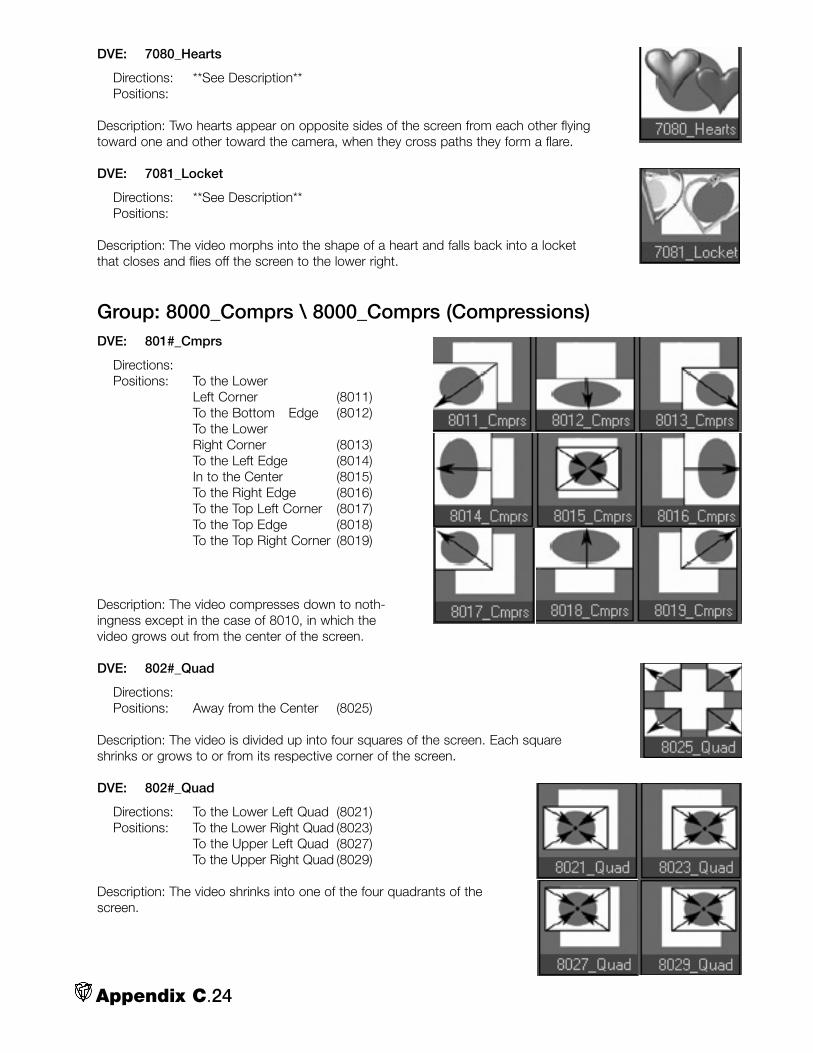
DVE: 7080_Hearts
Directions: **See Description**Positions:
Description: Two hearts appear on opposite sides of the screen from each other flyingtoward one and other toward the camera, when they cross paths they form a flare.
DVE: 7081_Locket
Directions: **See Description**Positions:
Description: The video morphs into the shape of a heart and falls back into a locketthat closes and flies off the screen to the lower right.
Group: 8000_Comprs \ 8000_Comprs (Compressions)DVE: 801#_Cmprs
Directions:Positions: To the Lower
Left Corner (8011)To the Bottom Edge (8012)To the Lower Right Corner (8013)To the Left Edge (8014)In to the Center (8015)To the Right Edge (8016)To the Top Left Corner (8017)To the Top Edge (8018)To the Top Right Corner (8019)
Description: The video compresses down to noth-ingness except in the case of 8010, in which thevideo grows out from the center of the screen.
DVE: 802#_Quad
Directions:Positions: Away from the Center (8025)
Description: The video is divided up into four squares of the screen. Each squareshrinks or grows to or from its respective corner of the screen.
DVE: 802#_Quad
Directions: To the Lower Left Quad (8021)Positions: To the Lower Right Quad (8023)
To the Upper Left Quad (8027)To the Upper Right Quad (8029)
Description: The video shrinks into one of the four quadrants of thescreen.
Appendix C.24

DVE: 802#_Horz
Directions:Positions: Shrinks OFF screen (8028)
Description: The video is divided in half horizontally and each section expands or con-tracts toward or from its respective edge of the screen.
DVE: 802#_Vert
Directions:Positions: Shrinks OFF screen (8026)
Description: The video is divided in half vertically and each section expands or con-tracts toward or from its respective edge of the screen.
Group: 9000_Borders DVE: 90##_Bars
Directions: ***See Description***Positions:
Description: This set of DVEs has two silver bars that work togetherin different ways as the border to the wipes. See list below:
(9011) Originating at the bottom Left Corner the bars scissor closethen slide toward the Left and Right respectively.
(9013) Originating at the Right Corner the bars scissor close thenslide toward the Right and Left respectively.
(9017) Originating at the Top Left Corner the bars scissor close thenslide toward the Left and Right respectively.
(9019) Originating at the Top Right Corner the bars scissor closethen slide toward the Right and Left respectively.
DVE: 904#_Chrome
Directions: From Lower left to Upper Right (9041)
Positions: From Top to Bottom (9042)From Lower Right to Upper Left (9043)From Right to Left (9044)From Left to Right (9046)
Description: These effects are very similar to a traditional wipe exceptthat an object covers the leading edge of the wipe. The object ofchoice for this set is a CHROME BAR.
Appendix C.25

DVE: 905#_Steel
Directions: From Lower left to Upper Right (9051)
Positions: From Top to Bottom (9052)From Lower Right to Upper Left (9053)From Right to Left (9054)From Left to Right (9056)From Bottom to Top (9058)
Description: These effects are very similar to a tra-ditional wipe except that an object covers the lead-ing edge of the wipe. The object of choice for thisset is a STEEL BAR with holes in it. (Think Erectorset.)
DVE: 908#_Glass
Directions: From Lower left to Upper Right (9081)
Positions: From Top to Bottom (9082)From Lower Right to Upper Left (9083)From Right to Left (9084)From Left to Right (9086)From Bottom to Top (9088)
Description: These effects are very similar to a tra-ditional wipe except that an object covers the lead-ing edge of the wipe. The object of choice for thisset is a Glass Rod.
DVE: 909#_Ingot
Directions: From Lower left to Upper Right (9091)
Positions: From Top to Bottom (9092)From Lower Right to Upper Left (9093)From Right to Left (9094)From Left to Right (9096)From Bottom to Top (9098)
Descriptions: These effects are very similar to a tra-ditional wipe except that an object covers the lead-ing edge of the wipe. The object of choice for thisset is a GOLD INGOT.
Appendix C.26

DVE: 911#_Litning
Directions: From Lower left to Upper Right (9111)
Positions: From Top to Bottom (9112)From Lower Right to Upper Left (9113)
From Right to Left (9114)From Left to Right (9116)From Bottom to Top (9118)
Description: These effects are very similar to a tra-ditional wipe except that an object covers the lead-ing edge of the wipe. The object of choice for thisset is a LIGHTNING BOLT.
DVE: 912#_Marble
Directions: From Lower left to Upper Right (9121)
Positions: From Top to Bottom (9122)From Lower Right to Upper Left (9123)From Right to Left (9124)From Left to Right (9126)From Bottom to Top (9128)
Description: These effects are very similar to a tradi-tional wipe except that an object covers the leadingedge of the wipe. The object of choice for this set isa MARBLE COLUMN.
DVE: 914#_Pencil
Directions:Positions: From Top to Bottom (9142)
Description: These effects are very similar to a traditional wipe except that an objectcovers the leading edge of the wipe. The object of choice for this set is a yellow PEN-CIL.
DVE: 916#_Rock
Directions:Positions: From Top to Bottom (9162)
From Right to Left (9164)From Bottom to Top (9168)
Description: These effects are very similar to a tradi-tional wipe except that an object covers the leadingedge of the wipe. The object of choice for this set isa chunk of ROCK.
Appendix C.27

DVE: 917#_Static
Directions: From Lower left to Upper Right (9171)
Positions: From Top to Bottom (9172)From Lower Right to Upper Left (9173)From Right to Left (9174)From Left to Right (9176)From Bottom to Top (9178)
Description: These effects are very similar to a tra-ditional wipe except that an object covers the lead-ing edge of the wipe. The object of choice for thisset is a band of STATIC.
Appendix C.28

*Portions of this glossary were originally published in newtekPRO magazine
NOTE:
All bolded words are defined in the Glossary.
Glossary.1
Glossary
by Paul Lara & Molly Dinkins
0 and 1 – The two numbers in the binary systemused to encode digital audio and digital video con-tent. See bit.
4:1:1 – The numbers represent video color spaceand refer to the sampling of luminance (4) and color(1,1) when a video signal is converted to a digital sig-nal. The luminance signal is sampled four times, whilethe color portion of the signal is sampled once (or for4:2:2, twice, etc.). The more samples, the sharperthe image (see 4:4:4). 4:1:1 is the color space usedwhen capturing DV footage and is the sampling usedfor NTSC. Though resulting in sharp imagery, threequarters of the color data is discarded, making itquite difficult to pull a clean key using DV footage.
4:2:0 – The sampling for PAL DV where the lastvalue, transparency, is discarded entirely. See 4:1:1.
4:2:2 – The specification for ITU-601 video. Thecolor data is sampled at half the horizontal samplingrate of the luminance, (but twice 4:1:1). While somecolor data is discarded, the difference is impercepti-ble to the human eye.
4:4:4 – Full resolution sampling of the color space.With no loss of data (RGB), 4:4:4 exceeds videorequirements, but is used for computer graphicsapplications. See 4:1:1.
5:1 – The video compression ratio for DV footage.
24-bit – In computer graphics, a pixel or dot com-
posed of 24 bits (8 for red, 8 for green, and 8 forblue). See 256.
32-bit – In computer graphics, 24-bit graphicdepth plus 8 bits for a secondary (alpha) channelthat stores 256 values of gray scale to indicate thetransparency of that pixel.
256 – In computer graphics, the available numberof selections for each individual color – red, blue orgreen (255 + 0 for the absence of color).Combinations of RGB (256 x 256 x 256) equal about16 million color variations per pixel, far more thanhumans can distinguish. A 255 in all 3 colors makeswhite; 0 in all colors makes black.
2D (2 dimensional) – A flat image.
3D (3 dimensional) – In LightWave’s Modeler mod-ule, virtual 2D and 3D objects and images are com-puter generated.
AC (Alternate Current) – An electric charge that regu-larly reverses direction as it travels through a conduc-tor. See volt, waveform, ampere, ohm. Compare DC.
additive color – The color theory used for broadcastand computers where color is a combination (byadding) of wavelengths of light that form the spec-trum of primary colors: red, green, blue (RGB). Thecolor of each pixel is a mix of the three primary colorsdetermined by the amount of energy in an electronstream. Compare subtractive color.

aliasing – An undesirable video and graphics proper-ty that appears as jagged edges (stair-steppingpixels) on the edge of an object, especially obviouson curved borders. See antialiasing.
alpha channel – A 256 gray scale color mask usedto select degrees of transparency values in an imageor video clip ranging between values of no trans-parency (255) to total transparency (0). VT[3] RTV val-ues can be saved with alpha channel informationembedded.
ampere (amp) – The standard unit of measure of thestrength of an electrical current produced by the forceof one volt passing through the resistance of oneohm.
analog – In video, data is sent by waves of electrici-ty, with voltage levels fluctuating continuously overtime, normally ranging between 0.7 to 1 volt. The VT[3] SX-8 (switcher expansion) module uses eitheranalog or digital signals. Compare digital.
anamorphic widescreen – A distortion appearing ina large number of DVD’s where the horizontal andvertical dimensions magnify differently by squeezing a1.78 picture shape into a 1.33 image area duringcapture. Anamorphic widescreen horizontallyuncompresses the picture for a widescreen TV setwith greater “vertical” information. Also annotated as16:9. See aspect ratio.
ANSI (American National Standards Institute) – anonprofit organization that promotes development oftechnological and electronic standards.
anti-aliasing – A computer graphic function thatblends the colors of adjacent pixels in order tosmooth the stair-stepping effect of aliasing.. artifacts – Undesirable elements or defects in a videopicture—anything that appears in the video that youdon’t want there, such as noise, pixelation, etc.
aspect ratio – The proportions of any monitor,defined by the width of a picture relative to its height.The aspect ratio for a standard television monitor is4:3, or 4 wide by 3 high. HDTV, also known aswidescreen, uses an aspect ratio of 16:9.
attenuation – A reduction in strength, electronicallymeasured in decibels (dBs). Turning down the vol-ume is an example, as is the attenuation occurringover long distances with digital or analog transmis-sions. Compare gain.
audio mixer – A device that controls multiple audioinputs and outputs. VT [3] offers an on-screen audio
mixer to control both outboard audio signals and theaudio of Toaster modules, such as DDR’s.
Aura – 2D video paint engine, (that is packaged withVT [3]), capable of painting and video layering as wellas pixel tracking and color isolation.
AVI (Audio Video Interleave) – A common video fileformat on PC’s and supported in VT [3].
background generator – A VT [3] module that cre-ates, loads and saves background color mattes foruse in live switching and production.
background render – The process in VT-Edit allow-ing the user to continue working while the computeris simultaneously creating a smaller file capable ofreal-time playback. This background task is complet-ed when the green “ready” line above the Play buttonin VT-Edit is lit.
balanced audio – Audio sent through a 3-wire con-ductor cable containing one wire with a positive signal, asecond with a negative signal, and a ground (carryingno signal). This separation allows longer cable-runs andlower chances of signal interference than unbalancedaudio connections. The negative and positive cablessend signals that are 180-degree opposites, while out-side noise is sent evenly along both cables. The bal-anced receiving device ignores the even signals anduses only the varying information from the two cables.
banding – A visual artifact where smooth color gradi-ents do not properly transition from one shade to thenext. The resulting color boundaries appear as‘bands’ in the image.
bandwidth – In computers, a measurement of thequantity of data that can be sent through a systemeach second. ITU-601 allows analog luminancebandwidth of 5.5MHz and chrominance bandwidthof 2.75MHz. It also refers to how much data inbytes that can be passed from computer storage toRAM (PCI bandwidth) and from the computer’s cen-tral processor to RAM (Front Side Bus bandwidth). Invideo, bandwidth refers to the range of frequencies,measured in Hz, that can pass through a device with-out distortion. A monitor’s refresh rate relies on highbandwidth: the higher the bandwidth, the more infor-mation you see and the sharper the picture you get.
baseband – Baseband transmission allows only onesignal at time to be carried across a wire, as is thecase with television broadcasting or computer net-works. Compare broadband.
Betacam – A component video tape format devel-oped by Sony.
Glossary.2

binary – A numeric system based on two values:zero or one, on or off. The binary system is the basisof digital computing.
bit (binary digit) – The smallest unit of data (com-posed of short pulses) in a computer or other digitalequipment. A bit can be only 0 or 1, on or off. It isalways represented in shorthand as a lower-case “b”.See bitmap.
bitmap – An image where brightness and color val-ues are mapped to each pixel. Video display is atype of bitmap. Bitmaps drop in quality once they areenlarged beyond their original size. Compare vectorgraphics.
black burst – A video signal composed of sync,black video and color burst that can be used to syn-chronize the timing of multiple video devices to thesame signal and color information. (See genlock). Invideo studios, black burst generators lock the entirefacility to a common signal called house sync orhouse black.
black level – Measured electronically, the blackestvideo signal that can be produced on a TV screen.On a waveform monitor, the NTSC black level is 7.5IRE units. The PAL level is 0 IRE. Any video darkerthan this will not be discerned on screen.
blanking – The invisible interruption of an electricalbeam as it scans a line of a fresh image onto a TVmonitor. Scanning from left to right every other line(either odd or even lines), the display interrupts (called horizontal blanking) to allow the beam toretrace to the left and down two lines. When thebeam reaches the lower right corner of the tube, thedisplay interrupts again (vertical blanking) until thebeam returns to the top left corner to begin tracingthe next field of the image.
blanking interval – The period of time when theelectron beam turns off (horizontal or vertical blank-ing) between scans of an image onto the screen.
blanking level – A low voltage (0 IEEE units) at theend of each horizontal picture line that separates thepicture information in the video signal from the syn-chronizing information. This voltage makes the elec-tron beam invisible as it retraces to draw the nextline.
blooming – An effect seen on a monitor when coloris too intense and bleeds over the edges of anobject, hence making thin lines and sharp edges lookthick and fuzzy. Blooming occurs when phosphors onthe screen cannot handle the energy sent from theelectron beam.
blue screen, green screen – The technique of film-ing or videotaping objects or talent in front of a deepblue (or green) wall or cloth (screen) to be electroni-cally replaced by another image. The weatherman isshot in front of a blue wall that will be replaced byweather maps.
BNC (British Naval Connector, Bayonet NutConnector) – The connectors on the ends of videocoaxial cables.
BOB (Breakout box) – Slang for SX-8 (switcherexpansion) unit.
breakout box (BOB)
broadband – A type of data transmission in which asingle medium (wire) can carry several channels atonce.
browse – To search through a data base.
buffer – A temporary computer storage area in mem-ory for data being transferred between devices thatoperate at different speeds.
bug – In video, slang for a logo in the lower corner ofthe screen, usually displayed as a downstream key.Also, bug is slang for a computer problem.
burst – A combination of sync, color burst andblack video. See colorburst.
bus – A data pathway. For example, the Switcherbus refers to Program, Preview and Key.
byte – 8 bits of data used to describe 256 discretevalues. Almost all computer speeds or storageamounts are referred to in bytes, (not bits). Highervalues include kilobyte (KB), (1000 bytes); megabyte(MB), (one million bytes); gigabyte (GB), (one billionbytes); terabyte (TB), (one trillion bytes); andpetabyte (PB), (a quadrillion bytes).
capture – The act of saving information or video tohard drives.
card – In computers, this refers to installable hard-ware. The VT hardware is often referred to as a cap-ture card.
cathode ray tube (CRT) – The principal technologybehind computer monitors and televisions. It worksby moving an electron beam across the face of thescreen. Each time the beam traces (or scans) a lineacross the inside of the tube, it lights up phosphordots, illuminating the active portion of the screen.
Glossary.3

CCIR (International Radio ConsultativeCommittee) – Formerly the global organizationresponsible for establishing television standards; nowregulated by ITU.
CD, (Compact Disc) – An optical disc format capa-ble of storing approximately 650 MBs of data.
CD-R (Compact Disc Recordable) – A type ofCDROM that can be written on by a CD recorderand read on a CDROM drive.
CDROM (Compact Disc Read-Only Memory) – Anoptical disc format that, once recorded on, can beread only.
CDRW (Compact Disc Rewritable) – An optical discformat that is erasable and reusable (or rewritable).
CG – In video, short for Character Generator. Also,computer graphics.
CGI (Computer Generated Imagery)
channel – An information pathway between twodevices.
character – A letter or a symbol comprising one byteof information. A character can also be unseen, like acarriage return.
character generator (CG) – A VT [3] module thatcreates titles, scrolls, and crawls.
chip – An integrated circuit containing millions oftransistors and other electronic components. Audio,video and computing itself are possible because ofthis technology.
chop – In VT [3], a capture function (Chop key)allows logging on the fly. When capturing video,chop stops the recording of one clip and immediatelybegins recording the next.
chroma key – In video, the process of revealing aportion of the background image by selecting a spe-cific color (or chrominance value) in the foregroundimage and making that chrominance transparent. Seeluma key, blue screen.
chrominance – The color value or color informationin the video signal. Saturation and hue are aspectsof chrominance. Luminance (black, gray, and white)have no chrominance.
clip – A video signal that has been digitized to disk.Also, a segment of video or film cut from a longersequence.
clipping – The process of cutting off a portion of thevideo signal because the image is too dark or (morecommonly), too bright. Also the cutting off of anaudio signal usually resulting in a distortion.
coaxial or coax cables – Cables used to transfervideo between cameras and recorders. Each consistsof a center conductor surrounded by an insulatingmaterial and a concentric outer conductor.Pronounced co-AXE.
CODEC (COmpression DECompression) – The vari-ous means of saving video files to computer, whilemaximizing storage space. AVI, MJPEG and Indeoare codecs. Also refers to the algorithm that handlesthe compression and decompression of video oraudio files.
color bars – A standard striped reference pattern ofeight established color values used to calibrate thecolor and luminance of video production monitors,cameras, recording and playback equipment.
color burst – A synchronization reference that givesfrequency and phase information about hue and sat-uration; the 8 to 10 cycles of unmodulated colorsubcarrier that enable color encoding of a compos-ite video signal and decoding in the receiver. Colormonitors use a color burst to decode the color por-tion of a video signal.See subcarrier..color correction – Electronically changing or correct-ing the color, tint, brightnessor shading of a video clip, which can be accom-plished in real-time using the Proc Amp in VT [3].
color mattes – Background colors used behind textand symbols.
color phase – The correct timing relationship in acolor display. Color is in phase when the hue isreproduced correctly.
color space – The geometric method for represent-ing color in 3-dimensional space. In video, the colorspace is defined in YUV; in computers as RGB.
color subcarrier – The frequency added to a lumi-nance signal that carries color information (3.58 MHzfor NTSC or 4.43 MHz for PAL signal). The subcarri-er frequency is too high to be detected by black andwhite televisions. Color televisions use circuitry thatdetects and decodes the color component for dis-play.
colorize – To color black and white images.
Glossary.4
common formats – See Formats, common.
component – A video signal that sends color infor-mation (chrominance and luminance) through threeseparate channels. The three channels can be RGB(Red, Green, and Blue) or YUV (where Y is luminanceand UV is chrominance). The component signal offersthe highest quality for production. . composite – A lower quality video signal that combinesthe chrominance, luminance, a sync pulse and colorburst information and sends it through one channel.
compressed – A lossy format of storing video orimages. Compare uncompressed.
compression – The process that decreases the datain a digital video so that it uses less storage spaceand transfers more quickly. Compareuncompressed.
computer graphics (CG) – Any graphic art or textitems created with a computer. VT [3], LightWaveand Aura are each capable versatile tools for graph-ics.
contract – In keying, refers to trimming, or contract-ing the edge of the key, which is useful to eliminatethe remaining color fringes around the object.See key choke.
CPU (computer processing unit) – The control unit ofa computer that executes instructions. CPU speed ismeasured in megahertz and gigahertz.
crawl – A line of text that moves horizontally acrossthe bottom of the screen, such as weather bulletins.Compare scroll.
Cross keyer – A specialized method of keying in VT[3] where multiple colors can be removed from theforeground layer of a video revealing a partial imagefrom the background layer or video clip. (Named forcreator Andrew Cross.)
crossfade – To fade out one audio track whileanother audio track simultaneously replaces it.Compare fade, dissolve.
crouton – File picture icon (or picon).
CRT (cathode ray tube)
cue – A “go” command to a person or device. DDRrunning in Cue mode, automatically pauses until theSwitcher tells it to roll.
D1 – A digital videotape format for recording and
playing back ITU-601 video, a component signal.Digitized video prevents problems such as genera-tion loss. Digital formats mainly use a 19mm widemagnetic tape (3/4”).
D2 and D3 – Digital videotape formats using com-posite video. Compare with D1, which uses compo-nent video. D2 is the tape standard for recordingcomposite signals.
DA (Distribution Amplifier) – An electronic box ordevice that enables a single audio or video signal tobe transmitted to several sources such as monitorsor projectors; or to send them amplified across alonger cable run.
dB (decibel) – The unit used to measure the strength ofaudio and video signals. Consider the volume of music:from barely heard (0 dB) to painfully loud (130 dB).
DC (Direct Current) – Electric charges that flow in onedirection through a conductor. Nearly all computerand electronic hardware require Direct Current.Compare AC.
DDR (Digital Disk Recorder) – In VT [3], a virtual tapedeck for capturing and playback of video andgraphics.
decibel (dB)
deck – Short for tape deck or video tape recorder orplayer.
deck controls – The buttons across the front of avideotape recorder or player to activate the video-tape, most typically including Pause, Rewind, Play,Stop, Fast Forward and Eject. VT [3] uses virtualdeck controls.
default (state) – The preset values that appear whenyou open a module in VT [3].
deinterlace – See interlace.
desktop – In VT [3], the monitor’s workspace. Six sep-arate desktops can be customized, saved and recalled.
differential gain – A change in luminance level thatcauses a change in the subcarrier amplitude of avideo signal. The television picture will show achange in color saturation caused by a simultaneouschange in picture brightness.
digital – A signal characterized by discrete states, 0or 1; on or off. Analog signals rise and fall as waves,whereas digital signals instantly switch betweenstates.
Glossary.5

digital video effects (DVE) – 3D video transitionson which video footage is mapped, like page curls.
Digital-S – A high quality, digital compressed (3:1)videotape format. The signal is captured in 4:2:2color space.
disc – A circular platter designed to be read or writ-ten to by lasers. Compact discs (CD) or digitalvideo discs (DVD). Not a disk.
disk – A circular platter that is coated with ironoxides. Small magnets then read and write informa-tion from the disk as it spins. Not a disc.
disk drives – A device that reads data stored ondisks.
dissolve – The dissolution of one video signal whileanother video signal simultaneously replaces it.Compare with fade.
distribution amplifier (DA)
dongle – A hardware key employed by softwaremanufacturers to ensure proof of ownership and dis-courage casual piracy.
download – Copying a file from the Internet oracross a network to one’s own computer.
downstream key (DSK) – A keyer that overlays text,video or graphics even while video transitions,switching or effects occur behind it.
drag – Pulling functions, information or imagesacross the computer screen by holding down amouse button while dragging the mouse.
drives –See Disk drives.
drop-frame timecode – A time measurement systemthat compensates for NTSC video that runs at 29.97frames per second. The counter skips counting(drops) two frames every minute except the tenth; itdrops 108 frames each hour. Since PAL runs precise-ly at 25 frames per second, it does not require drop-frame timecode.
dropout – A brief lapse of video or audio during play-back on a tape machine, caused by flaws in the tapeor a sudden loss of tape contact with the playbackhead.
DSK (downstream key) – Graphics or text superim-posed, or keyed downsteam of the primary switcher.This allows changing sources without interrupting thekey.
DV (Digital Video) – A tape format compressed at5:1 into a 4:1:1 signal.
DVCam – Sony’s particular flavor of the DV tape for-mat.
DVD (Digital Versatile Disc or Digital Video Disc) –The 12cm optical disc format used to distributemovies or to store more than 4.5 GB of data,Compare with CD.
DVE (Digital Video Effect) – See effect.
EDL (Edit Decision List) – An assembled list of editdecisions. Also a text file containing the timecodelocations of each clip used in a project which can berecalled at a later date for automated re-capture ofthe video. The list typically includes the source, the intime and time out for each edit, and transitions.
effects – Any modification of a video during captureor playback. This can include color-correction, blurring,or even superimposing titles or secondary images.
EFP (Electronic Field Production) – The equipmentand techniques for commercial and corporate videoproduction on location, or “in the field.”
ENG (Electronic News Gathering) – The accou-trement for gathering news and documentaries onlocation.
EPS (Encapsulated Postscript) – An Adobe imagefile format useful for its ability to be sized small orlarge without image degradation, because EPS filescreate a definition of all the lines and shapes in theimage, instead of mapping to individual pixels. (Seevector graphics.)
equalization – In audio, to improve sound quality byincreasing or decreasing the gain of the signal at vari-ous frequencies.
expansion module – An auxiliary component to theVT [3] Switcher, such as the SX-8 or the RS-8.
fade – To dissolve a video picture to a color, usuallyblack. In audio, to decrease the volume until it is nolonger audible. Compare dissolve.
field – One-half of an interlaced video picture; anNTSC field contains 262.5 lines while a PAL fieldcontains 312.5 lines (PAL). Two fields make up a sin-gle video frame. Fields are continuously “painted”every-other-line onto the TV monitor with the upper(or odd) field remaining on screen while replacing thelower (or even) field, then reversing the action to theupper, or odd field. See blanking.
Glossary.6

file – Any data saved on a computer.
file bin – The location where you store your clips.VT [3] offers file bins, which are actually Windows filefolders.
file formats – A listing of the most common comput-er formats for storage of graphics and video. InWindows, files are designated by “yourfilename.file-type” with the type is abbreviated to three letters;Macs often use four letters (.jpeg).
GRAPHICS FORMAT:.bmp – Windows bitmap image, uncompressed.iff – Interchange file format; primarily used on theAmiga.jpg (JPEG) – Compressed, popular for Internetgraphics.pcx – PC Paintbrush, uncompressed.pdf (Portable Document Format) – An AdobeSystems format used to encode text and imageslike manuals, and read with Acrobat.png (Portable Network Graphics) – A newer for-mat that can replace JPEG imagery, with or with-out alpha channel .tga (Targa) – High image quality, with or withoutalpha channel.tif (Tagged image file) – Uncompressed, with orwithout alpha channel
VIDEO FORMAT:.rtv (Real-Time Video) – VT [3]’s uncompressedformat.avi (Audio/Video Interleaved) – Uncompressed orcompressed.mpg (MPEG-1) – Highly compressed, useful forvideo playback on CD-ROM and the Internet..mp2 (MPEG-2) – Used for DVD.mov – Apple’s QuickTime movie format
AUDIO FORMATS:.wav – The audio standard on PC’s.aiff – The audio standard for Macs.au – The rare audio format for SUN computers.mp3 – Highly compressed audio format
ARCHIVAL FORMATS:.aur – Aura projects.dib – Aura brushes.lws – LightWave scene file.lwo – LightWave object file.zip – Popular file with high compression.sit – Popular Mac file with high compression
FireWire – A file transfer protocol (IEEE 1394)invented by Apple Computers to relay data betweendigital devices.
font – A single stylized alphabet with matching sym-bols .
frame – A complete video image that consists of twofields; a frame has 525 interlaced horizontal lines ofpicture information in NTSC, 625 in PAL.
frame buffer – The storage location in RAM for asingle frame of video.
frames per second (FPS) – The number of frames ineach second of video. NTSC uses 29.97 fps andPAL uses 25 fps.
frequency – The number of complete cycles of aperiodic waveform that occur in a given length oftime. Usually specified in cycles per second (Hertz).
Flyer – NewTek’s original nonlinear desktop editor forthe Amiga Toaster, released in 1994.
FXmonkey – The LightWave guide for creating pro-fessional flying logos.
gain – The level of amplification of a signal. Anincrease in signal power or voltage when a signal istransmitted from one point to another through anamplifier. Gain is expressed in decibels above a ref-erence level. Turning up the volume is an example ofgain; turning it down is attenuation.
garbage matte – A rough, simple overlay that iso-lates unwanted elements (like wires and signs) froman image.
general purpose interface (GPI) – A wired connec-tion allowing remote control over specific functions ofa device, like VT [3]’s GPI for the Switcher and DDR.Also a non-specific interface between equipment,usually a serial connection (RS232 or RS422 format)between computer modules.
generation – The number of duplications between anoriginal recording and a copy: Second generation is acopy of the original master; third generation is a copyof the copy of the original master, and so on.
generation loss – Loss of color, detail, sync, etc.,that appears when you copy a videotape. Tape andcircuitry limitations cause generation loss.
genlock (generator locking) – A device to electroni-cally synchronize several pieces of equipment suchas switchers and cameras. VT [3] internally genlocksall sources to the SX-8 switcher. An optional genlockcard can connect VT[3] to an external source calledhouse sync.
Glossary.7

George – A plain-language script used in Aura toautomate routine tasks.
gigabyte (GB) – 2 to the 30th power, or 1,024megabytes, roughly one billion bytes.
GPI (general purpose interface)
graticule – The fine lines of a grid overlaying wave-form and vectorscope monitors providing referencepoints for video calibration.
gray scale – The continuous tone in an image utiliz-ing the range of shades from black to white. Seealpha channel.
green screen – See blue screen.
ground – Electrically, a wire that conveys an electriccurrent to the earth (or ground), resulting in protectionagainst electric shock. Also, a ground can provide ashield from other electrical interference.
ground wire –The third wire in a grounded connec-tion that ensures the signal will be isolated fromexternal interference. In audio, this wire protectsagainst interference that may cause a backgroundhum. See balanced audio.
GUI (Graphical User Interface) –An interface employ-ing visuals and graphics to make software easier andquicker to use, in contrast to Command interfacessuch as DOS, where commands are entered in astext. Pronounced goo-ee.
hard drive – Large capacity computer storage unitsof multiple stacked disks, sealed in airtight cases thatspin at high speeds inside the computer.
HDTV (high definition TV) – HDTV systems use 1125lines of horizontal resolution (compared to 525 forNTSC and 625 for PAL) and an aspect ratio of 16:9.This gives an image quality approaching that of35mm film photography.
hertz (Hz) – An international unit of frequency equalto one cycle per second.
hi res – Slang for high resolution. Sometimes spelledrez.
horizontal blanking – The process when an electronbeam on a monitor shuts off, or is blanked, so thatthe beam can return to the left side of the screen tobegin a new scan line. See blanking and retrace.
house sync – A synchronized electronic signalshared by all audio and video equipment in a studio.
HSL (Hue, Saturation and Luminance) – In comput-er graphics, a method of representing color valuesfrom the 360 degree color wheel. Hue is pure color;saturation is the amount of color: and luminance isbrightness. Compare RGB.
Hub – A LightWave utility that transfers real-timeupdates of models and textures between Modelerand Layout.
hue – In HSL, the dominant wavelength that distin-guishes a particular color. The actual color is repre-sented by degrees in the color wheel, i.e. 240º isblue.
hum – An unwanted mix of 60Hz power sine waveinto other electrical signals. In audio, a hum can beheard; in video, hum appears as waves in the picture.
IDE (Integrated Drive Electronics) – An interface forstorage devices such as hard drives and CD-ROMs.
IEEE (Institute of Electrical and Electronics Engineers)– A group best known for formation of standards forcomputing.
IEEE 1394 – See FireWire.
illegal color – A color that cannot be reproduced ona standard TV. Use RGB and YUV colors for broad-casting.
impedance – The opposition, or load, to a signal.Circuits for audio or video signals work with a certainload, or impedance; typical video impedances: 75ohm or High Z.
Indeo – An audio/video codec with variable com-pression rates designed primarily for Internet use.
input – Anything going into a computer or tape deckis input, whether from a camera, a tape, or a mouse-click.
interface – The location where you interact with yourcomputer, often comprised of on-screen menus andbuttons. See GUI.
interlacing – Each video frame is divided into twofields; interlacing is the process of scanning everyother line of the fields so that the two fields dove-tailor interweave together. See blanking. Compare pro-gressive.
interleaved – Simultaneous reading or writing ofdata. AVI interleaves audio and video into the samefile.
Glossary.8

Internet (Inter-network) – The Internet is an ever-expanding global network of computers.
I/O (input/output)
IRE (Institute of Radio Engineers) – A measurement ofthe luminance of the video signal that divides 1 voltof Peak-Peak video into 140 IRE units. The IRE unit ismeant to make the numbers for luminance levels eas-ier to communicate. The amplitude of the video signalfrom blanking (zero volts) to peak white is 0.714286volts or 100 IRE units. Synchronization signals extendfrom blanking to - 0.285714 volts or - 40 IRE units.
ITU (International Telecommunication Union) – Anorganization headquartered in Geneva, Switzerlandresponsible for adopting international treaties, regula-tions and standards to coordinate global telecom net-works and services for governments and the privatesector. See ITU-601.
ITU-601 – The definitive standard for D1 componentvideo.
JKL keys – Deck controls keys: “k” stops and startsplayback, “j” slows it down, and “l” speeds it up.
jog – To rewind or fast forward your video. Jog isslower than shuttle and permits viewing frame byframe; it includes audio.
JPEG (Joint Photographic Experts Group) – A lossycompression technique ranging from 2:1 up to100:1. See file format.
key – The technique of replacing a brightness value(luma key) or a specific color value, (chroma key) witha still image, video clip or live camera shot. VT [3]’s 4:2:2uncompressed video improves pulling a clean key.
key choke – Reducing the outermost edge in achroma key by trimming pixels. See contract.
kilobyte (KB) – 1024 bytes, rounded off to 1000.
lavaliere microphone – A small microphone that isattached to clothing, often used for live TV interviews.
Layout – LightWave’s digital stage where objects,lights and cameras are positioned to create a scene.
LED (Light Emitting Diode) – A light such as a tally oran on/off button. LED’s are also combined to createmassive video billboards at casinos and stadiums.
LightWave® 3D (LW) – NewTek’s 3D modeling, sur-facing, animation, and rendering software available onthe PC or Mac, (and bundled in VT [3]).
lines – A measure of resolution in video. In NTSC,525 lines of information are scanned on a monitoracross a single frame, every other line at a time,starting from top left down to bottom right. The firstpass scans the odd lines, the second, the even ones.See blanking.
live – Videotaping or broadcasting an event as it hap-pens.
log – A descriptive list of shots, (if video, usuallyincluding a timecode). The VT[3] chop key allowslogging on the fly.
lossy – The elimination (or loss) of information when afile is compressed. Continuous saving and re-savingfurther degrades the image or video.
lo res – Slang for low resolution. Sometimes spelledrez.
luma key – In video, the process of revealing a back-ground image by selecting a specific luminancevalue (black, white or a gray scale) in the foregroundand making that luminance value transparent. Seechroma key.
luminance – The amount of light radiating from acomputer image or video signal. In HSL, the bright-ness (the lightness and darkness of color). 0 lumi-nance is no color; 100% is full color. Also, the blackand white portion of the video signal.
LW (LightWave)
machine control – Remote control of externaldevices, such as tape decks, by a live switcher orcomputer.
Main – The primary Switcher image in VT [3] beforeadding downstream key images.
Megabyte (MB) – 2 to the 20th power, or roughlyone million bytes.
Megahertz (MHz) – One million cycles (hertz) persecond.
mint – Slang for a VT [3] module, such as theSwitcher or VT-Edit.
microphone preamplifier – A signal path enhancer.Microphones produce very low signal levels and apreamplifier boosts to the output signal to a levelcompatible with audio circuitry.
MHz – Abbreviation for megahertz, a unit of meas-urement for a million cycles per second.
Glossary.9

MJPEG (Motion JPEG) – The application of JPEGcompression to frames of video.
MPEG (Motion Pictures Experts Group) – An organi-zation that defines standards for compression ofmoving pictures. (See File Formats.)
Modeler – The LW module where 3D objects arecreated and surfaced.
Module – Any single component within the VT [3]suite, such as the Switcher or Color Picker.
monitor – A display device for computer or videoimages.
motherboard – The computer’s main circuit boardconnecting all other devices.
multi-cam – Slang for multiple-camera recording orediting.
multi-format – VT [3]’s ability to capture and playback footage from a wide variety of compressed oruncompressed formats.
multimedia – A presentation, delivered through a com-puter, that combines different types of content (video,audio, still images, graphics, animation, text, etc.).
network – A collection of computers all linkedtogether to share data.
noise – Disturbance or interference to an electricalsignal. Video noise appears as snow, graininess,ghost images or picture static induced by externalsources such as the national power-line grid, electricmotors, fluorescent lamps, etc. Audio noise appearsas hiss, hum and/or static.
non-interlaced – Compare progressive.
non-linear – In editing, the ability to rearrange cap-tured clips in a quick, flexible manner irrespective oftheir original order on tape.
NTSC (National Television Systems Committee) – Thestandard established for color television in NorthAmerica, parts of South America, and Japan. NTSChas 525 lines of information, played back at a rate ofapproximately 30 frames(29.97) per second at 60Hz. See PAL.
offline – Production editing of lower resolution thanbroadcast standards; when a vast amount of rawfootage exists, it is often captured at low resolution todetermine final edits, then only necessary clips are re-digitized in full resolution. Compare online.
ohm – The unit of measure for electrical resistance. Aresistance of 1 ohm will pass 1 ampere of currentwhen a voltage of 1 volt is applied.
online – Editing at final, highest-quality output, usedfor broadcast or distribution. Compare offline.
on-the-air – The action in front of the camera isbeing broadcast over the air, or distributed internallyvia closed-circuit tv. See live.
open architecture – A computer or peripheral withpublished specifications that allow third-party devel-opment.
optical disc format – A storage medium where datais written as pits in a groove on a plastic coated discand read by lasers. (Some authorities use the worddisk instead of disc.) See disc, CD and DVD.
output – The audio and video signals emanating fromproduction equipment.
output bus – Any signal coming from VT [3], such asProgram Out or Downstream Key.
overlay – To superimpose two or more images ontop of one another, where portions of the topimage(s) are transparent, revealing the image(s)below. Common in video titling.
overscan – Video images may exceed the size of thescreen on a consumer monitor by five to ten percent.This excess video leaves some flexibility so that theactive image will appear correctly on a variety of tele-vision sets. Video professionals plan for critical actionto occur only in the center, which is the safe area.Professional monitors can display the overscan area.The area inside a 10% line is the safe title area. Theoverscan Test Pattern is VE T15 C7 or VE T17 C8.
PAL (Phase Alternate Line) – The standard for televi-sion broadcasting in Western Europe featuring 625lines per frame and 25 frames per second at 50 Hz.
PCI (Peripheral Component Interconnect) – The datapathway between the computer and all installedcards. The bus (chip) communicates large amountsof information (high bandwidth) to the motherboard,usually 32-bit or 64-bit.
petabyte – 2 to the 50th power, or roughly onequadrillion bytes. Yes, one thousand terabytes. YIKES!
phantom power – The power supplied from theaudio mixer board back to a sensitive microphoneneeding direct current. VT [3] provides phantom micro-phone power through the SX-8 Switcher module.
Glossary.10
phase – The timing of a signal in relation to anothersignal; the timing of a color in relation to the colorburst signal, so if you change the subcarrier phase ofvideo, you change the hue of the colors in the signal.
PICON (picture icon) – In VT [3], croutons.
picture-in-picture (PiP) –The act of overlaying one ormore smaller images on an image or video stream.VT-Edit can create an unlimited number of PiPs in avideo stream.
PiP (picture in picture)
pixel (picture element) – A single (rectangular shaped)dot of light and color within a graphic or video asseen on the monitor. The number of the pixils deter-mines the resolution of the image. The higher theresolution, the more detailed the image.
pixelation – A distortion of a digital image exposingthe rectangular pixels. Especially pronounced whenan image is magnified.
pixel tracking – An animation technique to lock oneanimation or video stream to another, based on theknown location of pixels in the original.
playback – The playing of audio or video tape. Aplayback deck only plays and does not record.
polygon – A flat plane object consisting of three ormore connected lines. LightWave uses polygons toconstruct 3D objects.
post, post production – The assembling of the finalprogram: The process of editing, adding graphics,creating special effects, color correcting, and audiomixing after the footage is shot. VT [3] is a completepost production package.
preference settings – Values entered on the VT [3]Preferences panel that designate items like DefaultStill Length.
Preview – The Switcher bus in VT [3] ready for out-put – cued with video, graphics or a rolling camera –next in line to go live.
proc amp (processing amplifier) – The device used invideo production to match the various incoming sig-nals, especially useful in a multi-cam environment toensure comparable colors. VT [3] offers on-boardProc Amps for each input into the system.
Program, Program Out – The video stream going“on the air,” a combination of the Main input and anyadditional graphics or key layers.
progressive – The combining of both fields in aninterlaced frame into an image, especially helpfulwhen the final output is destined for an Internetstream or DVD. VT [3 ] can capture interlaced or pro-gressive mode footage. Compare interlace.
proxy render – The Aura function that continues toupdate any changes made in Aura’s timeline as abackground task, allowing Aura animations to beimmediately viewed or sent to either Program or Keyout.
peripheral – An auxiliary computer device, such as aprinter or CDROM.
PSA (Public Service Announcement) – A free TV orradio broadcast of an announcement (or commercial)for a non-profit organization.
pull a key – Slang for creating a chroma key.
pulse – A brief surge characterized by a rise and fall,such as with an electronic signal. A video pulse is acarrier for all the synchronous data corresponding toa given time stamp in a stream.
QuickTime – An Apple Computer audio/video fileformat that can be streamed over the Internet.
RAID (Redundant Array of Independent Drives) –RAID combines multiple small, inexpensive diskdrives into a single logical drive or “disk array” withperformance that exceeds a more expensive high-speed disk drive. VT [3] uses RAID 0, or software-striped drives.
RAM (Random Access Memory) – Memory that canbe written to or read by the CPU. VT [3] requires atleast 512 MB of RAM.
raster – The horizontal scan lines on a video display.
real estate – Slang for the amount of computerscreen space you have available for your work.
real-time – An operating mode where the computerreceives and processes data almost instantly, hencereal-time, so that the user does not wait while thecomputer processes or renders the output.
reboot – The act of re-starting a computer. There aretwo types of reboots: A warm boot is a reset of theoperating system without powering down; a coldboot involves physically shutting down the powersupply and then re-starting.
res – (Or rez). Slang for resolution.
Glossary.11

reset – The process of returning a computer or mod-ule back to its default state.
resolution – In computer graphics, the quality of animage measured by the quantity of pixels; in video,as lines.
retrace – An electron beam scans a picture onto ascreen from left to right; before scanning the nextline, the beam must return to the left side of thescreen, an action called retrace. See blanking.
RGB (red, green, blue) – The basic components of thecolor television system. Also they are primary colors,(not to be confused with the painter’s primary paletteof red, blue and yellow). RGB colors are defined bymixing red, green and blue in values from 0 to 255. Inthis additive scheme, 255 R + 255 G + 255 B =white. All 0 values = black. Also one of the colorpalettes used for computer displays. See YUV andY/V. Compare additive color with subtractive color.
RS (recommended standard) – A set of standards forserial connections adopted by the Electrical IndustriesAssociation.
RS-8 – NewTek’s physical switcher interface, with T-bar and buttons to provide a tactile control surfacefor technical directors.
RS–232 – An older communication standard replacedby RS-422.
RS-422 – A newer standard for serial connectionssupporting higher data rates and greater immunity toelectrical interference. The VT [3] SX-8 switcherexpansion unit contains three RS-422 ports.
RTV (real-time Video) – The uncompressed videoformat used by VT [3]. RTV files can also containalpha channel information.
rundown – A production outline for the crew thathighlights shots, angles, and locations of lights andtalent during any given scene.
safe area or safe action area – The inner 80% ofthe video screen where images and action can safelybe placed to be seen on most consumer TVs.
safe title area – The inner area of the video screenwhere titling is recommended for standard TV’s,smaller than the safe action area.
sampling – The examination and capture of a signalbased on a brief time span. In audio, sample ratesare expressed by how many thousand cycles aresampled and captured per second. See Kilohertz. In
video, sample rates are expressed as ratios betweenthe three video components (Y, R-Y, B-Y). See 4:1:1,4:2:2. Compare compression.
saturation – In the HSL, the percentage of white inthe color, or the density of color.
scan – The mechanical optical movement in succes-sive lines across a surface that reproduce or transmitan image.
scan lines – The individual lines within each field ofvideo. See field.
scanner – An optical (image acquisition) device usedto copy and convert a printed image or page of textinto a computer display.
scroll – The vertical movement of text or images onthe video. Compare crawl.
scrub – With a mouse, grabbing an arrow or icon offthe GUI and moving it back and forth to engage orsee the full range of the selected item (such as avideo clip). The movement resembles scrubbing.
SCSI (Small Computer System Interface) – A stan-dard high-speed parallel connection between thecomputer and peripheral devices, such as diskdrives, scanners and tape drives. Pronouncedscuzzy.
SDI (Serial Digital Interface) – A system of receivingand transmitting digital audio and video signals, idealfor long cable runs in post production houses.
serial digital video – A digital tape format that storesvideo at a standard of 270 Mb/sec SMPTE 259Mcomponent digital signal.
serial port – A computer l/O (input/output) port onthe computer. The serial port uses a single wire orpair of wires to transmit and receive data to and fromexternal devices. The standard serial port uses RS-232 or RS-422 protocols.
shuttle – You can quickly fast forward or rewind (theimage and audio) to scan video footage. Compare jog.
signal – A waveform that sends information fromone point to another.
signal-to-noise ratio (S/N) – The strength of anaudio or video signal in relation to background noise.The ratio is measured in decibels. A higher ratio invideo gives you a cleaner picture, with less snow. Ahigher ratio in audio gives you cleaner sound.
Glossary.12

sine, sine wave – A fundamental waveform pro-duced by periodic, regular oscillation.
skins – The application of customized imagebitmaps positioned over a hidden computer controlpanel which alter the look of a module interface.
slo-mo – Slang for slow motion.
SMPTE (Society of Motion Picture and TelevisionEngineers) – A global organization based in theUnited States that sets standards for baseband visu-al communications, including film and video..
SMPTE 259M – The standard for storing serial digi-tal video.
source, source material – The original footage usedto create a video program.
spot – Slang for a commercial .
stillstore – A device that sequences or randomlyaccesses a library of single frame images (stills).
stop motion – The technique of capturing a singleframe of film or video, stopping to adjust the objectsand or actors, before capturing the next frame.
storyboard – A graphic representation (on whatevermedium: paper, blackboard or computer) of a video,animation or film project. The storyline is illustratedindicating talent positions, camera angles, edits, etc.
storyboard editor – VT [3]’s editing system in whicha single crouton represents a clip. The program isedited by arranging and rearranging croutons, andinserting transitions. Storyboard editing is valuablefor quickly roughing out a project.
stream – Any continuous flow of data, such as audioor video.
streaming – The technique of sending audio andvideo across the Internet for remote viewing.
striped drives – Two or more hard drives joinedtogether by the computer’s operating system to readand write a single file across the multiple drives,resulting in increasing bandwidth.
subcarrier (phase) – The electrical portion of a videosignal that determines hue (color).
subtractive color – Color produced by light reflectedfrom a surface, as compared to additive color.Subtractive color includes hues in color photos and col-ors created by inks on paper. Compare additive color.
S-VHS (Super-VHS) – An improved version of theVHS tape format capable of recording higher pictureresolution.
S-Video (Separated Video) – A video signal that sep-arates brightness or luminance (Y) from the chromi-nance (C) data. See Y/C.
sweetening – Slang for the post-production processof enhancing audio and acoustics of the sourcematerial.
switcher – A real-time device enabling a seamless(usually live) change of video inputs without interrup-tion or glitching. See SX-8.
SX-8 (switcher expansion) – The VT [3] Switcherexpansion module, with 100 connectors for video,audio, and external machine control.
sync (synchronization) – The precise alignment of twovideo signals or functions. Horizontal sync is a timingpulse that identifies the start of each new line. Verticalsync identifies the start of a new field. Color burst, async reference, sends frequency and phase informa-tion.
sync pulse – The signal that conforms different videoequipment to each other. If all your video gear is amarching band, then think of the sync pulse as thedrum major.
T[3] – Short for VT [3].
talent – An actor, newscaster, weatherman, etc., whowill appear on screen.
tally, tally lamp – The signal light or LED atop a stu-dio camera, signaling on-set personnel which camerais active, especially important when switching live.
tape – Short for videotape or audio tape.
Targa (TGA) – See File Formats.
TBC (time-base corrector) – A device that correctsproblems with sync pulses by generating a cleantime-base, and synchronizing incoming video to thisreference.
TEd – A nickname for Toaster Edit, The nonlineareditor in Video Toaster [2].
terabyte – 2 to the 40th power, or roughly one trillionbytes.
test pattern – Pattern of colours, lines and/or shapesdesigned to assist equipment calibration.
Glossary.13

time lapse – The technique for compressing time byrepeatedly capturing one frame of video, pausing,and then capturing another. When played back, itspeeds up the action, such as a flower blooming in a30 second clip.
timecode – The unique reference on each frame ofvideo, read as 00:00:00:00, HH:MM:SS:FF (Hours,Minutes, Seconds and Frames), hence enabling pre-cise edits.
timeline – The visual representation of video clips oranimations as a horizontal strip of film.
titling – Text and graphics added to a video image.
tracking – The angle and speed at which the tapepasses the video heads. Due to small differences inhead-to-tape alignment between VCRs, it is some-times necessary to adjust the tracking control on aVCR when playing a tape recorded on another deck.Also, for CG effects, a term referring to the trackingof moving objects in shots, especially necessarywhen integrating CG animations with live action.
transitions – VT [3]’s generic effects used to end oneclip and introduce another, such as a dissolve.
TrueType™ – The font format used by MicrosoftWindows™.
TWAIN (Quote from Rudyard Kipling, “never the twainshall meet” or Technology Without An Interesting Name)–A non-profit organization with a sense of humor thatestablishes the public standard to regulate communica-tion between software applications and image acquisitiondevices, such as scanners and digital cameras.
unbalanced audio – A two-wire audio connection.Unbalanced audio is more susceptible to interferenceor noise on long cable runs than balanced audio.
uncompressed – A lossless means of storing video,ITU-601, or images. Compare compressed.
underscan – The portion along the outside edges ofvideo not visible on regular TV sets. Production moni-tors provide an underscan mode to expose anyproblems during the blanking, and at the beginningand end of scan lines and frames.
vector graphics – Mathematically derived, objectscreated by a collection of lines, instead of individualpixels. Compare bitmap.
vectorscope – A device displaying an objective elec-tronic measurement of the chrominance in a videosignal. See waveform.
VHS – A popular consumer videotape format.
video – Recorded electronically, these capturedmoving images (and stills) are stored, transmitted andultimately reproduced on an electronic device, (suchas a TV), by horizontally scanning lines of an analogelectronic signal. Also, the visual portion of television.
video bandwidth – The range between the lowestand highest signal frequency of a given video signal.In general, the higher the video bandwidth, the bet-ter the quality of the picture.
video capture card – PCI card that lets you recordvideo onto your computer’s hard drive. These cardsuse hardware and/or software compression (CODEC)to digitize the video onto your hard drive.
video legalize – A filtering process to ensure that allcolor values will conform to the video broadcastspecification. Since computer paint programs cancreate colors outside the broadcast specs, VT [3]provides a video legalize filter.
video stream – Any distinct video or animation that isplayed back.
virtual BOB – On-screen representation of the SX-8.
volt – A unit of electrical pressure. One volt is theelectrical pressure that will cause one ampere of cur-rent to flow through one ohm of resistance.
voltage – Electromotive force expressed in volts.
VT-Edit – VT [3]’s nonlinear editor offering real-time,multi-format playback.
VT-Scope – VT [3]’s waveform monitor and vec-torscope.
VTR (Video Tape Recorder) – A recording deck. Mostprofessionals use the Betacam format.
VT-Vision – The onscreen monitors provided withinVT [3] for viewing the Main, Preview, Program, Keyand Downstream Key busses.
WAV – See File Formats.
wave – In physics, a series of advancing impulsesgenerated by a disturbance, (in video, stimulated byelectric current or voltage). At any instant of time, awave is described by its “height” (amplitude) and its“length” (wavelength). Equally important is the phaseof the wave, which is the number that describes theposition of the “crests” or “troughs” with respect to agiven reference position.
Glossary.14

waveform – Electric impulses, or waves, come inmany shapes (round, sawtoothed, square).The round-ed sine wave is the most familiar waveform.
waveform monitor – The device displaying an objec-tive electronic measurement of the luminance (bright-ness) of a video signal. See vectorscope.
white balance – The adjustment of the camera tothe temperature of light source in the shot.
white level – The brightness of the brightest portionof the video image.
Windows 2000, Windows XP – Graphical operatingsystems created by Microsoft and used by VT [3].
work area – The CG page or space on the screenwhere your creativity can be seen.
work space – All the computer screens you areusing for VT[3]; your real estate.
XLR – A very robust, three-pin locking connectorwidely used in professional audio; also called aCannon connector after one of its most prominentoriginal manufacturers.
Y/C (Luminance / Chrominance) – A signal thatseparates video into luminance (Y) and chrominance(C). The chrominance combines the U and V from theYUV color system. Also called S-Video.
YUV – A color system that separates video into oneluminance portion (Y) and two chrominance por-tions (UV): the U for blue, the Y for red. YUV, or com-ponent, is a professional format.
zebra – Not the animal, the stripes. This phraserefers to the angled stripes that appear on VT-Visionmonitors and professional camera viewfinders toindicate that video is either approaching or exceed-ing nominal brightness. VT-Vision zebra indicates thatvideo is exceeding 70 IRE.
Glossary.15

Notes:
Glossary.16