Hardware Hacking : Have Fun While Voiding Your Warranty
577
-
Upload
khangminh22 -
Category
Documents
-
view
2 -
download
0
Transcript of Hardware Hacking : Have Fun While Voiding Your Warranty


H ave Fu n W h i l e Vo i d i n g Yo u r Wa r ra n t y
HARDWAREHACKING
287_HRD_HACK_FM.qxd 1/15/04 8:53 AM Page i


Joe Grand Author of Stealing the Network
Ryan Russell Author of Stealing the Network and
Hack Proofing Your Network, Second Edition
And featuring Kevin D. Mitnick Technical Reviewer
Foreword by Andrew “bunnie” Huang
Lee Barken Marcus R. Brown Job de Haas Deborah KaplanBobby Kinstle Tom Owad Albert Yarusso
H ave Fu n W h i l e Vo i d i n g Yo u r Wa r ra n t y
HARDWAREHACKING
287_HRD_HACK_FM.qxd 1/15/04 8:53 AM Page iii

Syngress Publishing, Inc., the author(s), and any person or firm involved in the writing, editing, or production (col-lectively “Makers”) of this book (“the Work”) do not guarantee or warrant the results to be obtained from theWork.
There is no guarantee of any kind, expressed or implied, regarding the Work or its contents.The Work is sold ASIS and WITHOUT WARRANTY.You may have other legal rights, which vary from state to state.
In no event will Makers be liable to you for damages, including any loss of profits, lost savings, or other incidentalor consequential damages arising out from the Work or its contents. Because some states do not allow the exclu-sion or limitation of liability for consequential or incidental damages, the above limitation may not apply to you.
You should always use reasonable care, including backup and other appropriate precautions, when working withcomputers, networks, data, and files.
Syngress Media®, Syngress®,“Career Advancement Through Skill Enhancement®,”“Ask the AuthorUPDATE®,” and “Hack Proofing®,” are registered trademarks of Syngress Publishing, Inc.“Syngress:TheDefinition of a Serious Security Library”™,“Mission Critical™,” and “The Only Way to Stop a Hacker is toThink Like One™” are trademarks of Syngress Publishing, Inc. Brands and product names mentioned in thisbook are trademarks or service marks of their respective companies.
KEY SERIAL NUMBER001 HJIRTCV764002 PO9873D5FG003 829KM8NJH2004 B7NMW3V9KM005 CVPLQ6WQ23006 VBP965T5T5007 HJJJ863WD3008 2987GVTWMK009 629MP5SDJT010 IMWQ295T6T
PUBLISHED BYSyngress Publishing, Inc.800 Hingham StreetRockland, MA 02370
Hardware Hacking: Have Fun While Voiding Your Warranty
Copyright © 2004 by Syngress Publishing, Inc.All rights reserved. Printed in the United States of America.Except as permitted under the Copyright Act of 1976, no part of this publication may be reproduced or dis-tributed in any form or by any means, or stored in a database or retrieval system, without the prior written per-mission of the publisher, with the exception that the program listings may be entered, stored, and executed in acomputer system, but they may not be reproduced for publication.
Printed in the United States of America1 2 3 4 5 6 7 8 9 0ISBN: 1-932266-83-6Technical Editor: Joe Grand Cover Designer: Michael KavishTechnical Reviewer: Kevin D. Mitnick Copy Editor: Darlene BordwellAcquisitions Editor: Catherine B. Nolan Indexer: J. Edmund RushPage Layout and Art: Patricia Lupien Editorial Assistant: Michael Rubin
Distributed by O’Reilly & Associates in the United States and Jaguar Book Group in Canada.
287_HRD_HACK_FM.qxd 1/15/04 8:53 AM Page iv

Acknowledgments
v
We would like to acknowledge the following people for their kindness and support in making this book possible.
To Jeff Moss and Ping Look of Black Hat for being great friends and supporters of Syngress.
A special thanks to Kevin Mitnick for sharing his invaluable expertise and knowledge, and to Darci Wood for hersupport of this book and the Syngress publishing program.
Syngress books are now distributed in the United States by O’Reilly & Associates, Inc.The enthusiasm and workethic at ORA is incredible and we would like to thank everyone there for their time and effort in bringingSyngress books to market:Tim O’Reilly, Laura Baldwin, Mark Brokering, Mike Leonard, Donna Selenko, BonnieSheehan, Cindy Davis, Grant Kikkert, Opol Matsutaro, Lynn Schwartz, Steve Hazelwood, Mark Wilson, RickBrown, Leslie Becker, Jill Lothrop,Tim Hinton, Kyle Hart, Sara Winge, C. J. Rayhill, Peter Pardo, Leslie Crandell,Valerie Dow, Regina Aggio, Pascal Honscher, Preston Paull, Susan Thompson, Bruce Stewart, Laura Schmier, SueWilling, and Mark Jacobsen.
The incredibly hard working team at Elsevier Science, including Jonathan Bunkell, Duncan Enright, DavidBurton, Rosanna Ramacciotti, Robert Fairbrother, Miguel Sanchez, Klaus Beran, and Rosie Moss for makingcertain that our vision remains worldwide in scope.
David Buckland, Wendi Wong, Daniel Loh, Marie Chieng, Lucy Chong, Leslie Lim,Audrey Gan, and JosephChan of STP Distributors for the enthusiasm with which they receive our books.
Kwon Sung June at Acorn Publishing for his support.
Jackie Gross, Gayle Voycey,Alexia Penny,Anik Robitaille, Craig Siddall, Darlene Morrow, Iolanda Miller, JaneMackay, and Marie Skelly at Jackie Gross & Associates for all their help and enthusiasm representing our productin Canada.
Lois Fraser, Connie McMenemy, Shannon Russell, and the rest of the great folks at Jaguar Book Group for theirhelp with distribution of Syngress books in Canada.
David Scott,Tricia Wilden, Marilla Burgess,Annette Scott, Geoff Ebbs, Hedley Partis, Bec Lowe, and Mark Langleyof Woodslane for distributing our books throughout Australia, New Zealand, Papua New Guinea, Fiji Tonga,Solomon Islands, and the Cook Islands.
Winston Lim of Global Publishing for his help and support with distribution of Syngress books in the Philippines.
To all the folks at Malloy who have made things easy for us and especially to Beth Drake and Joe Upton.
287_HRD_HACK_FM.qxd 1/15/04 8:53 AM Page v

287_HRD_HACK_FM.qxd 1/15/04 8:53 AM Page vi

vii
Technical Editor & Contributor
Joe Grand; Grand Idea Studio, Inc. Joe Grand is the President and CEO of Grand IdeaStudio, a product design and development firm that brings unique inventions to marketthrough intellectual property licensing. Many of his creations, including consumer electronics,medical products, video games and toys, are sold worldwide.
A recognized name in computer security and electrical engineering, Joe’s pioneeringresearch on product design and analysis, mobile devices, and digital forensics is published invarious industry journals. He is a co-author of Hack Proofing Your Network, Second Edition(Syngress Publishing, ISBN 1-928994-70-9) and Stealing The Network: How to Own the Box(Syngress, ISBN 1-931836-87-6).
Joe has testified before the United States Senate Governmental Affairs Committee on thestate of government and homeland computer security, and is a former member of the leg-endary hacker think-tank, L0pht Heavy Industries. He has presented his work at numerousacademic, industry, and private forums, including the United States Naval Post GraduateSchool Center for INFOSEC Studies and Research, the United States Air Force Office ofSpecial Investigations, the USENIX Security Symposium, and the IBM Thomas J. WatsonResearch Center. Joe holds a BSCE from Boston University.
Joe is the author of Chapter 1 “Tools of the Warranty Voiding Trade,” Chapter 2 “ElectricEngineering Basics,” Chapter 3 “Declawing Your CueCat,” and Chapter 13 “Upgrading Memory onPalm Devices.”
287_HRD_HACK_FM.qxd 1/15/04 8:53 AM Page vii
viii
Lee Barken (CISSP, CCNA, MCP, CPA) is the co-director of the StrategicTechnologies and Research (STAR) Center at San Diego State University. He hasworked as an IT consultant and network security specialist for Ernst & Young’sInformation Technology Risk Management (ITRM) practice and KPMG’s Riskand Advisory Services (RAS) practice. Lee is the co-founder of the San DiegoWireless Users Group and writes and speaks on the topic of wireless LAN tech-nology and security. He is the technical editor for Mobile Business Advisor Magazine,and the author of How Secure Is Your Wireless Network? Safeguarding Your Wi-Fi LAN(ISBN: 0-13-140206-4).
“Let’s be grateful for those who give us happiness; they are the charming gardeners who make our soul bloom.” —Marcel Proust
With deepest appreciation for my charming gardeners, a special thank you tomy love Stephanie, my mom and dad, Frieda and Israel, my brothers, Derren andMartin, my sister Randi and her husband Scott, my Uncle Harry and myGrandmother Sophie.Thank you for your support and love.
Lee is the author of Chapter 10 “Wireless 802.11 Hacks.”
Marcus R. Brown is a software engineer at Budcat Creations. His work includeswriting low-level drivers and system-level programming such as resource manage-ment, file loading, and audio streaming. He is currently working on an unan-nounced title for the PlayStation 2 and Xbox. Marcus lives in Las Vegas, Nevada.
Marcus is the author of Chapter 9 “Hacking the PlayStation 2.”
Contributors
287_HRD_HACK_FM.qxd 1/15/04 8:53 AM Page viii

ix
Job de Haas is Managing Director of ITSX BV, a Dutch company located inAmsterdam. ITSX BV provides security testing services in the broadest sense. Job isinvolved in testing, researching, and breaking security aspects of the latest tech-nologies for corporate clients. In assignments for telecommunication operators andmobile phone manufacturers, Job gained experience with the internal operations ofmodern phones.
Job holds a master’s degree in electrical engineering from Delft TechnicalUniversity. He previously held positions at the Dutch Aerospace Agency (NLR) asa robotics researcher and at Digicash BV as a developer of cryptographic applica-tions. He lives in Amsterdam,The Netherlands.
Job is the author of Chapter 12 “Can You Hear Me Now? Nokia 6210 Mobile PhoneModifications.”
Deborah Kaplan (PCP) is an independent consultant focusing on revision controlsystems, system administration tools, release engineering, and open-source software.Deborah has developed enterprise-wide technology infrastructure, integratingtelecommunications with heterogeneous Windows and UNIX environments. Shespecializes in building tools that automate repetitive tasks and monitor systems forperformance tuning.
Deborah holds a bachelor’s degree from Haverford College and a master’sdegree from Simmons.
Deborah is the author of Chapter 14 “Operating Systems Overview” and Chapter 15“Coding 101.”
Bobby Kinstle works in the Reliability Engineering department at AppleComputer, Inc. where he performs destructive simulations of extreme use and abuseof the products. His specialties are performing voltage and frequency margin analysisas well as detailed thermal performance studies. He also performs environmentaltesting, mechanical shock and vibration, and repetitive stress testing. Bobby alsodesigned and built the lab’s test network of over 600-switched Ethernet ports with4-gigabit fiber optic backbones and NetBoot servers as well as the department datacenter. When projects are slow Bobby teaches Mac OS X Server training classeswithin the company.
287_HRD_HACK_FM.qxd 1/15/04 8:53 AM Page ix
x
Bobby is the author of Chapter 4 “Terabyte FireWire Hard Drive Case Mod” and a co-author of Chapter 5 “Macintosh Hacks.”
Tom Owad is the owner and Web master of Applefritter, www.applefritter.com, acommunity where the artist and the engineer meet.Applefritter provides its mem-bers with discussion boards for the exchange of ideas and hosts countless member-contributed hardware hacks and other projects.Tom is pursuing a Bachelor’sDegree in Computer Science and International Affairs from Lafayette College,Pennsylvania.
Tom is a co-author of Chapter 5 “Macintosh Hacks.”
Ryan Russell has worked in the IT field for over 13 years, focusing on informa-tion security for the last seven. He was the primary author of Hack Proofing YourNetwork, Second Edition (Syngress Publishing, ISBN 1-928994-70-9) and Stealing theNetwork: How to Own the Box, Syngress Publishing (ISBN: 1-931836-87-6, and is afrequent technical editor for the Hack Proofing series of books. He is also a tech-nical advisor to Syngress Publishing’s Snort 2.0 Intrusion Detection (ISBN: 1-931836-74-4). Ryan founded the vuln-dev mailing list, and moderated it for three yearsunder the alias “Blue Boar.” He is a frequent lecturer at security conferences, andcan often be found participating in security mailing lists and website discussions.Ryan is the Director of Software Engineering for AnchorIS.com, where he’s devel-oping the anti-worm product, Enforcer. One of Ryan’s favorite activities is disas-sembling worms.
Ryan is the author of Chapter 6 “Home Theater PCs.”
287_HRD_HACK_FM.qxd 1/15/04 8:53 AM Page x

xi
Albert Yarusso is a principle of Austin Systems (www.austinsystems.com), an Austin,Texas-based firm that specializes in web design programming and hosting services.Albert’s background consists of a wide range of projects as a software developer, withhis most recent experience focused in the game industry.Albert previously workedfor Looking Glass Technologies and more recently for Ion Storm Austin, where hehelped create the highly acclaimed PC game “Deus Ex.”
Albert co-founded AtariAge (www.atariage.com) in 2001, a comprehensive web-site devoted to preserving the history of Atari’s rich legacy of video game consolesand computers, which has become one of the busiest destinations on the web forclassic gaming fans. In 2003,Albert helped bring the first annual Austin GamingExpo (www.austingamingexpo.com) to Austin, an extremely successful event thatdrew over 2,000 visitors in its first year.
Albert is the author of Chapter 7 “Hack Your Atari 2600 and 7800,” Chapter 8“Hack Your Atari 5200 and 8-Bit Computer,” and Chapter 11 “Hacking the iPod.”
287_HRD_HACK_FM.qxd 1/15/04 8:53 AM Page xi

xii
Andrew “bunnie” Huang (PhD) is a staff engineer with Luxtera, and a part-timeresearch staff with the California Institute of Technology. He also heads up a privateconsultancy firm, Xenatera LLC. bunnie is the author of Hacking the Xbox. bunniehas a broad background in electronics and firmware that comes in handy for var-ious hardware hacking and reverse engineering projects. bunnie holds a PhD,M.Eng, and SB from the Massachusetts Institute of Technology, and is a member ofthe IEEE. He lives in San Diego, CA, with his fiancée, Nicole Justis.
Kevin D. Mitnick is a security consultant to corporations worldwide and acofounder of Defensive Thinking, a Las Vegas-based consulting firm (www.defen-sivethinking.com). He has testified before the Senate Committee on GovernmentalAffairs on the need for legislation to ensure the security of the government’s infor-mation systems. His articles have appeared in major new magazines and trade jour-nals, and he has appeared on Court TV, Good Morning America, 60 Minutes, CNN’sBurden of Proof and Headline News, and has been a keynote speaker at numerousindustry events. He has also hosted a weekly radio show on KFI AM 640, LosAngeles. Kevin is also author of the best-selling book, The Art of Deception:Controlling the Human Element of Security.
Foreword Contributor
Technical Reviewer
287_HRD_HACK_FM.qxd 1/15/04 8:53 AM Page xii

Contents
xiii
Foreword xxvii
Introduction xxxv
Part I Introduction to Hardware Hacking 1
Chapter 1 Tools of the Warranty Voiding Trade 3Introduction 4The Essential Tools 4Taking it to the Next Level 6Hardcore Hardware Hackers Only 8Where to Obtain the Tools 10
Chapter 2 Electrical Engineering Basics 13Introduction 14Fundamentals 14
Bits, Bytes, and Nibbles 14Reading Schematics 18Voltage, Current, and Resistance 20
Direct Current and Alternating Current 21Resistance 22Ohm’s Law 22
Basic Device Theory 23Resistors 23Capacitors 25Diodes 28Transistors 30Integrated Circuits 32
Soldering Techniques 34
287_HRD_HACK_TOC.qxd 1/14/04 7:45 PM Page xiii

xiv Contents
Hands-On Example: Soldering a Resistor to a Circuit Board 34
Desoldering Tips 36Hands-On Example: SMD Removal Using ChipQuik 37
Common Engineering Mistakes 40Web Links and Other Resources 41
General Electrical Engineering Books 41Electrical Engineering Web Sites 42Data Sheets and Component Information 43Major Electronic Component and Parts Distributors 43Obsolete and Hard-to-Find Component Distributors 43
Part II Hardware Hacks 45
Chapter 3 Declawing Your CueCat 47Introduction 48
Model Variations 49Opening the CueCat 51
Preparing for the Hack 51Opening the Four-Screw PS/2 CueCat 51Opening the Two-Screw PS/2 CueCat 54Opening the USB CueCat 55
Removing the Unique Identifier 56Preparing for the Hack 57Removing the UID: Four-Screw PS/2CueCat 57Removing the UID:Two-Screw PS/2CueCat 60Removing the UID: USB CueCat 62Under the Hood: How the Hack Works 64
Removing the Proprietary Barcode Encoding 68Preparing for the Hack 68Removing the Encoding from the Four-Screw PS/2
CueCat 69Removing the Encoding from the Two-Screw PS/2
CueCat 71Removing the Encoding from the USB CueCat 73Under the Hood: How the Hack Works 74
287_HRD_HACK_TOC.qxd 1/14/04 7:45 PM Page xiv

Contents xv
Technical Information 76The CueCat Encoding Scheme 76More Physical Model Variations 78More History of Political and Legal Issues 80
CueCat Litter Box: Web Links and Other Resources 82Open-Source CueCat Software and Drivers 83DigitalConvergence Patents for CueCat Technologies 83
Chapter 4 Case Modification: Building a Custom Terabyte FireWire Hard Drive 83
Introduction 84Case Mod Primer 84
Creating a 1.2TB FireWire RAID 85Preparing for the Hack 85Performing the Hack 86Under the Hood: How the Hack Works 92
Custom Case Modification for the FireWire RAID 94Preparing for the Hack 94Performing the Hack 95Under the Hood: How the Hack Works 105
Additional Resources 108Case Modifications 109
Chapter 5 Macintosh 111Compubrick SE 112
Preparing for the Hack 113Performing the Hack 114
Taking Apart the Mac 114Encasing the Speaker 120Covering the Mouse and the Keyboard 121Encasing the Disk Drive 123Encasing the Hard Drive 125Encasing the Motherboard 127Encasing the CRT 129
How the Hack Works 131Building a UFO Mouse 132
287_HRD_HACK_TOC.qxd 1/14/04 7:45 PM Page xv

xvi Contents
Preparing for the Hack 133Performing the Hack 134
Opening the Mouse 134Drilling the Hole 136Soldering the LED 137Reassembling the Mouse 138
How the Hack Works 140Adding Colored Skins to the Power Macintosh G4 Cube 140
Preparing for the Hack 141Performing the Hack 142Under the Hood: How the Hack Works 145
Other Hacks and Resources 145Desktop Hacks 145Laptop Hacks 146Electrical and Optical Hacks 146Case Mods 146Software 147Discussion 147
Chapter 6 Home Theater PCs 149Introduction 150Before You Begin: Research and Plan 151
How Much Could It Cost? 152Did Someone Already Build It? 153
The Components of an HTPC Project 154The Display 155
What Are Your Options for Higher-Quality Video Display? 157
The Video Card 160The Case 160The Hard Drives 161
Speed Considerations 163Sshhhh... Quiet Operations 164
Optical Drives 164The CPU 165The Sound Card 166
287_HRD_HACK_TOC.qxd 1/14/04 7:45 PM Page xvi

Contents xvii
The Controller 167The Software 167
Building a Windows HTPC 171Preparing for the Hack 171Performing the Hack: Software 175
Eazylook 177Using the Launcher 178Using Guide Plus+ 178CDex 180FairUse 180
Windows Summary 185Building a Linux HTPC 185
Preparing for the Hack 185Performing the Hack: Hardware 185Performing the Hack: Software 192
Installing the Video Capture Drivers 192Install MPlayer and CODECs 194Installing MythTV 194
Linux Summary 197Further Hacking and Advanced Topics 198
Chapter 7 Hack Your Atari 2600 and 7800 199Introduction 200
The Atari 7800 ProSystem 201Hacks in This Chapter 202
Atari 2600 Left-Handed Joystick Modification 202Preparing for the Hack 203Performing the Hack 204
Use an NES Control Pad with Your 2600 207Preparing for the Hack 207Performing the Hack 209
Atari 2600 Stereo Audio Output 214Preparing for the Hack 216Performing the Hack 216Under the Hood: How the Hack Works 223
Atari 7800 Blue LED Modification 223
287_HRD_HACK_TOC.qxd 1/14/04 7:45 PM Page xvii

xviii Contents
Preparing for the Hack 223Performing the Hack 224Under the Hood: How the Hack Works 227
Atari 7800 Game Compatibility Hack to Play Certain 2600 Games 228Preparing for the Hack 229Performing the Hack 230Under the Hood: How the Hack Works 232
Atari 7800 Voltage Regulator Replacement 232Preparing for the Hack 233Performing the Hack 233Under the Hood: How the Hack Works 236
Atari 7800 Power Supply Plug Retrofit 237Preparing for the Hack 238Performing the Hack 239
Other Hacks 2422600 Composite/S-Video Modifications 242Atari 7800 Composite and S-Video Output 243Sega Genesis to Atari 7800 Controller Modification 243NES Control Pad to Atari 7800 Controller Modification 243Atari 7800 DevOS Modification and Cable Creation 243Atari Resources on the Web 244
Chapter 8 Hack Your Atari 5200 and 8-Bit Computer 247Introduction 248
The Atari 5200 SuperSystem 249Hacks in This Chapter 250
Atari 5200 Blue LED Modification 250Preparing for the Hack 251Performing the Hack 251Under the Hood: How the Hack Works 256
Creating an Atari 5200 Paddle 256Preparing for the Hack 257Performing the Hack: Disassembling the Paddle
Controller 258
287_HRD_HACK_TOC.qxd 1/14/04 7:45 PM Page xviii

Contents xix
Performing the Hack: Building the 5200 Paddle Controller 260Performing the (Optional) Hack: Weighted Dial 266
Under the Hood: How the Hack Works 267Free Yourself from the 5200 Four-Port Switchbox 268
Preparing for the Hack 269Performing the Hack 271Under the Hood: How the Hack Works 279
Build Atari 8-Bit S-Video and Composite Cables 280Preparing for the Hack 281Performing the Hack 282Cable Hack Alternatives 288Under the Hood: How the Hack Works 289Technical Information 289
Other Hacks 290Atari 5200 Four-Port VCS Cartridge Adapter Fix 290Atari 5200 Composite/S-Video Modification 290Atari 8-Bit SIO2PC Cable 291Atari Resources on the Web 291
Chapter 9 Hacking the PlayStation 2 293Introduction 294Commercial Hardware Hacking: Modchips 294Getting Inside the PS2 296
Mainboard Revisions 296Identifying Your Mainboard 297
Opening the PS2 298Installing a Serial Port 302
Preparing for the Hack 303Performing the Hack 304
Testing 309Under the Hood: How the Hack Works 310
Booting Code from the Memory Card 310Preparing for the Hack 310Performing the Hack: Preparing Title.DB 311
Choosing BOOT.ELF 313
287_HRD_HACK_TOC.qxd 1/14/04 7:45 PM Page xix

xx Contents
Saving TITLE.DB to the Memory Card 314Independence! 314
Under the Hood: How the Hack Works 314Other Hacks: Independent Hard Drives 316PS2 System Overview 316
Understanding the Emotion Engine 317The Serial I/O Port 318
The I/O Processor 321The Sub-CPU Interface 321
Additional Web Resources 321
Chapter 10 Wireless 802.11 Hacks 323Introduction 324Wireless NIC/PCMCIA Card Modifications:
Adding an External Antenna Connector 325Preparing for the Hack 326Performing the Hack 327
Removing the Cover 327Moving the Capacitor 329Attaching the New Connector 331
Under the Hood: How the Hack Works 332OpenAP (Instant802): Reprogramming Your Access Point
with Linux 332Preparing for the Hack 333Performing the Hack 334
Installing the SRAM Card 335Power Me Up, Scotty! 338
Under the Hood: How the Hack Works 338Having Fun with the Dell 1184 Access Point 338
Preparing for the Hack 339Performing the Hack 340Under the Hood: How the Hack Works 345
Summary 345Additional Resources and Other Hacks 345
User Groups 345Research and Articles 346
287_HRD_HACK_TOC.qxd 1/14/04 7:45 PM Page xx

Contents xxi
Products and Tools 346
Chapter 11 Hacking the iPod 349Introduction 350Opening Your iPod 353
Preparing for the Hack 354First Generation iPods 355Second and Third-Generation iPods 356
Replacing the iPod Battery 359Preparing for the Hack 360Battery Replacement: First- and Second-Generation iPods 361Battery Replacement:Third-Generation iPods 365
Upgrading a 5GB iPod’s Hard Drive 371Preparing for the Hack 372Performing the Hack 372
From Mac to Windows and Back Again 381Preparing for the Hack 381Going from Windows to Macintosh 381Going from Macintosh to Windows 383
iPod Diagnostic Mode 384The Diagnostic Menu 384Disk Check 387
Additional iPod Hacks 388Installing Linux on an iPod 388Repairing the FireWire Port 388Scroll Wheel Fix 389
iPod Resources on the Web 390
Chapter 12 Can You Hear Me Now? Nokia 6210 Mobile Phone Modifications 391
Introduction 392Nokia 6210 LED Modification 393
Preparing for the Hack 393Performing the Hack 395
Opening the Nokia 6210 395Removing the Old LEDs 400
287_HRD_HACK_TOC.qxd 1/14/04 7:45 PM Page xxi

xxii Contents
Inserting the New LEDs 401Increasing the LED Power 402Putting the Phone Back Together 403
Under the Hood: How the Hack Works 404Data Cabling Hacks 406
Data Cables 407Flashing Cables 410Net Monitor 411
Other Hacks and Resources 415
Chapter 13 Upgrading Memory on Palm Devices 417Introduction 418
Model Variations 419Hacking the Pilot 1000 and Pilot 5000 420
Preparing for the Hack 420Removing the Memory Card 422
Adding New Memory 423Under the Hood: How the Hack Works 427
Hacking the PalmPilot Professional and PalmPilot Personal 429Preparing for the Hack 429
Removing the Memory Card 429Adding New Memory 430
Under the Hood: How the Hack Works 433Hacking the Palm m505 436
Preparing for the Hack 436Opening the Palm 437Removing the Main Circuit Board 439Removing the Memory 441Adding New Memory 442Under the Hood: How the Hack Works 445
Technical Information 447Hardware 447File System 448Memory Map 448
287_HRD_HACK_TOC.qxd 1/14/04 7:45 PM Page xxii

Contents xxiii
Database Structure 449Palm Links on the Web 450
Technical Information 450Palm Hacks 450
More Memory Upgrades 450
Part III Hardware Hacking Technical Reference 451
Chapter 14 Operating Systems Overview 453Introduction 454OS Basics 454
Memory 455Physical Memory 455Virtual Memory 457
File Systems 458Cache 459Input/Output 460Processes 460System Calls 461Shells, User Interfaces, and GUIs 461
Device Drivers 462Block and Character Devices 464
Properties of Embedded Operating Systems 466Linux 467
Open Source 467History 468Embedded Linux (uCLinux) 469Product Examples: Linux on Embedded Systems 470
VxWorks 470Product Examples: VxWorks on Embedded Systems 470
Windows CE 471Concepts 471
Product Examples: Windows CE on Embedded Systems 472
Summary 473Additional References and Further Reading 473
287_HRD_HACK_TOC.qxd 1/14/04 7:45 PM Page xxiii

xxiv Contents
Chapter 15 Coding 101 475Introduction 476Programming Concepts 476
Assignment 477Control Structures 478
Looping 479Conditional Branching 480Unconditional Branching 481
Storage Structures 482Structures 483Arrays 484Hash Tables 485Linked Lists 486
Readability 488Comments 488Function and Variable Names 488Code Readability: Pretty Printing 489
Introduction to C 490History and Basics of C 490
Printing to the Screen 490Data Types in C 493Mathematical Functions 493
Control Structures 496For Loops 496While Loops 496If/Else 498Switch 500
Storage Structures 501Arrays, Pointers, and Character Strings 501Structures 506
Function Calls and Variable Passing 507System Calls and Hardware Access 508Summary 509
Debugging 509Debugging Tools 509
287_HRD_HACK_TOC.qxd 1/14/04 7:45 PM Page xxiv

Contents xxv
The printf Method 510Introduction to Assembly Language 512
Components of an Assembly Language Statement 513Labels 513Operations 515Operands 515
Sample Program 516Summary 518Additional Reading 518
Index 519
287_HRD_HACK_TOC.qxd 1/14/04 7:45 PM Page xxv

287_HRD_HACK_TOC.qxd 1/14/04 7:45 PM Page xxvi

Hacking—and in particular, hardware hacking—has experienced a bitof a renaissance recently. I am personally quite pleased about theincreased interest in hacking.Your interest in this book, HardwareHacking: Have Fun While Voiding Your Warranty, is a testament to theincreased demand for knowledge about hardware hacking. I’d like totake a few pages and a few minutes of your time to share with youwhy your interest in the topic makes me happy as a fellow hardwarehacker.
First allow me to pontificate on the meaning of the word hack.Theterm has evolved quite dramatically over the years. Hacking has shapedtechnology perhaps as much as technology has shaped our perceptionof the hacker.According to The New Hacker’s Dictionary (a public-domain lexicon of jargon created by hackers, www.jargon.8hz.com):
hack: 1. /n./ Originally, a quick job that produces what isneeded, but not well. 2. /n./ An incredibly good, and perhapsvery time-consuming, piece of work that produces exactlywhat is needed. 1
The second sense of the word is perhaps the closest to the defini-tion I associate with the word hack.Thus, it follows that a hacker is onewho labors to create good, typically innovative solutions to targetedproblems.This book you are about to read was editted by a truehacker, Joe Grand, and it speaks mostly to the class of hacks thataddress the need to adapt and improve on existing consumer solutions.
As you can see, my view of hacking is a rather romantic and ideal-ized one. I eschew the Hollywood stereotype of a hacker as a slovenly,socially maladept person with a bent for vengeance, data theft, or per-
xxvii
Foreword
287_HRD_HACK_Fore.qxd 1/14/04 7:09 PM Page xxvii

haps a penchant to blithely play a game of deploy-the-nuke insideNORAD’s computers.Although there are certainly such elements intoday’s hacker culture, I prefer to focus on promoting the more sociallyredeeming aspects of hacking. I believe that hacking is rooted in a desireto play with and understand technology, a modern manifestation of thevalues of exploration, passion, and hard work that date back to the firstexplorers and settlers of this country. Furthermore, hacking is a kind ofgrass-roots technology movement, in contrast to the kinds of technologymovements that are forwarded by corporations and governments.As aresult, hackers tend to play the part of proxy for the masses when it comesto sorting out the interplay of technology, society, and business.As tech-nology continues to infuse our daily lives, it is becoming more importantfor society to bring its representatives to the technology direction table.
It is interesting and perhaps informative to see how hardware hackinghas evolved over the years. In the early days of electronics, common hob-byists—hackers of sorts, but the term wasn’t coined back then—couldcobble together unique, useful, and sometimes outright impressive piecesof hardware that could match commercially available products in both per-formance and quality. In fact, some of the projects that hackers laboredover in their garages went on to form the roots of today’s technology.
Roll the calendar back to 1938:A young Bill Hewlett and DavePackard get together and invent, in their garage, a high-quality piece ofaudio test equipment, the HP200A resistance-capacitance audio oscillator.Hewlett and Packard continued on to found the company we know today,and its rich history of engineer-friendly products helped forge the tech-nology base we now enjoy. Most people are familiar with HP as a manu-facturer of computers and printers, but HP’s richest contributions totechnology have been through enabling technologies, such as the toolsengineers require to do their jobs. I myself use an HP48GX calculator, andI have an HP1650B logic analyzer on my desk, on top of my oldHP8410C network analyzer.
Another well-recognized example of a company and technology withroots in the hacker community is Apple Computer. Roll back to 1976:Steve Wozniak debuts the Apple I at the Homebrew Computer Club inPalo Alto, California.The Apple I was designed over a period of years as ahobby machine, a true product of the hacking culture.Wozniak joined
www.syngress.com
xxviii Foreword
287_HRD_HACK_Fore.qxd 1/14/04 7:09 PM Page xxviii
Foreword xxix
www.syngress.com
forces with Steve Jobs, and the two went on to found the Apple Computerthat brought us the Apple II and the now ubiquitous Macintosh computer.
The gritty grass-roots hacking culture in the early days of electronicstechnology served as a kind of incubator for innovation that has resulted inmany of the products we enjoy today. Hewlett and Packard, Jobs andWozniak are just two examples of the influence of the hacker spirit on oursociety.The basic values of hacking—creating a good thing that is exactlywhat is needed at a particular time—are a good match with innovation.Furthermore, hackers’ independently motivated nature means that thousandsof ideas are tested and built by hackers in the absence of venture capital orthe risk constraints of investors. Hackers play an important part in thegrowth of technology, so I am always pleased to see a greater interest andawareness of hacking in the general public.
Recently, hacking has taken on more of a software-oriented bent.This isdue in part to the steady pace of hardware improvement guaranteed byMoore’s Law. Hardware hacking is a time-consuming labor of love, and it isdiscouraging to know that almost any hack you can think of to double acomputer’s performance will be obsolete within 12 months. It is much morerewarding to work in the instant-gratification world of software and let theperformance of your programs ride the Moore’s Law wave.
Another factor working against hardware hackers is the barrier of entrythat was created by the higher levels of integration that naturally followed asa result of Moore’s Law.The hackability of the desktop PC met a turningpoint in the evolution of the IBM PC-XT to the IBM PC-AT.The IBMPC-XT motherboard was chiefly composed of chips that were essentiallynaked logic gates.This was very hacker-friendly, since most of the core func-tionality was exposed at a human-friendly scale.The IBM PC-AT, on theother hand, was one of the first desktop computers to use VLSI chips for theprocessor support logic. I remember my first look at the PC-AT mother-board: I was hoping to be able to read the board like a book, with all thelogic gates’ part numbers gleaming in their fresh white silkscreen against thematte epoxy bodies of chips.What I saw instead was a closed book; therewere perhaps three or four curious, high pin-count chips with part numbersand a manufacturer’s logo I had never seen before.These chips were propri-etary, and any hope of a deeper level of understanding or hardware explo-ration seemed to be dashed.
287_HRD_HACK_Fore.qxd 1/14/04 7:09 PM Page xxix

I think perhaps a lot of prospective hardware hackers felt the same wayaround then, because since then hacking has taken on a distinct software-ori-ented slant. Some of the most famous hackers today are renowned for theirsoftware contributions. Richard Stallman and Linus Torvalds are perhapshousehold names among the technological elite due to their fantastic contri-butions to free software through GNU and Linux.The best part about soft-ware hacking is its very low barrier of entry.Any willing youth with access toa computer and an Internet connection can plug into any of the various freesoftware efforts and make a contribution to the technology collective.All thetools required to generate high-quality code are virtually free, and aside fromthe time investment, it costs nothing to use them. On the other hand, hard-ware hacking has a very real entry cost associated with the activity; there is abare minimum set of tools that are needed on a daily basis, and an unfortu-nately large and diverse assortment of expensive, specialized tools is requiredto accomplish specific jobs. Furthermore, producing a hardware hack typicallyrequires real materials in addition to time and energy, thereby placing creativeand/or bold (read: risky) hardware-hacking projects beyond the financialhorizon of most young folk. Given that human nature is to follow the path ofleast resistance, it is no surprise that hacking today is primarily a softwareaffair.
In a twist of fate, recent macro-economic and social trends have worked toreverse the trend and bring more people into hardware hacking.The detritus ofthe dot-com bubble created fertile soil for sprouting hardware hackers.Anoverall reduction in demand for components, design, and manufacturing serviceshas resulted from the economic slowdown. High-quality, used test equipment istrickling down into the ranks of hackers, either snatched off the shelf of deadcompanies or snapped up for pennies on the dollar at auction. Scrap compo-nents are also finding their way into distribution, driving down componentprices. Combined with an overall soft demand situation, individual hackers areable to command the same level of service and component choice as large cor-porations. Furthermore, fabrication and assembly services have been forced todrive their prices down, to the point where hardware hackers could purchasehigh-tech, custom-built multilayer boards for under $50 per board.
Hardware design tool vendors also experienced a corresponding priceadjustment due to the economic slowdown. Perhaps the most significantrecent technological change for hardware hackers is the introduction of pro-
www.syngress.com
xxx Foreword
287_HRD_HACK_Fore.qxd 1/14/04 7:09 PM Page xxx

fessional-grade FPGA design tools for free.The motivating theory for thisdevelopment is that FPGA manufacturers could “hook” more designers into aparticular brand or architecture if an effective and powerful set of design toolswere made freely available. Stiff competition and hungry manufacturers helpedensure that a very featureful set of tools found their way into the market at avery low barrier of entry.
The significance of easy and affordable FPGA development systems cannotbe understated. FPGAs have the effect of transforming the traditional solder-and-wires world of hardware hacking into the much more accessible and morewidely understood code-and-compile world.A single hardware hackerworking alone or in a small group can realistically build a complex micropro-cessor using FPGAs.This kind of activity was unheard of before the advent ofFPGAs.Also, the availability of “programming languages” for hardware thatcould be translated into FPGA configurations meant that software hackerscould cross over into hardware hacking without much formal training in tra-ditional hardware design and assembly.
I can relate a personal example of the positive impact of the economicslowdown on hobbyists and hackers. During the buildup to the dot-com bust,it was literally impossible to buy high-quality tantalum and ceramic capacitorsof the type used in compact/mobile switching power supplies. Chronic short-ages due to explosive demand for portable and mobile electronic technologiesmeant that hackers had to compete toe-to-toe with large OEMs for pricingand component availability. I remember back around 2000 looking for samplesof the AVX TPS “low-ESR” capacitors for a demonstration project I wasbuilding. I swept through every distributor I knew of, and all of them wereposting lead times of months, with minimum buy quantities in the thousands.Ultimately, I had to do a minor last-minute redesign of the circuit just beforesending the board for fabrication to compensate for the lack of high-qualitycapacitance. In contrast, just last month I cranked out a design that used anAVX TPS capacitor, and multiple hacker-friendly (i.e., high in-stock avail-ability, credit card payment terms, and low minimum buy restrictions) distrib-utors posted thousands of parts in their inventories. It certainly was pleasant tobe able to access, with great ease, the same quality of components that the “bigboys” use.
Although the confluence of recent macro-economic events set the stagefor hardware hacking to regain popularity, this alone is not enough.
www.syngress.com
Foreword xxxi
287_HRD_HACK_Fore.qxd 1/14/04 7:09 PM Page xxxi

Remember, hacking is a fundamentally grass-roots activity, and it does nothappen on a large scale unless there is some kind of social drive to motivatepeople into action.
A small part of the renewed social awareness in hardware hacking may bedue to the desire of young hackers to extend themselves and carve a new nichefor themselves.The software hacking world is now more structured, and newhackers joining one of the major software hacking establishments feel more likecogs rather than inspired inventors. Change and new ideas are not always sowelcome from so-called “n00bs,” and some budding hackers may be turned offby the intense flame wars that are sometimes triggered by a newbie suggestionor mistake.
However, this kind of sociopathy is probably not the real drive behind therenaissance of hardware hacking. I feel that the larger impetus is the recentpertinence of reverse-engineering consumer hardware. Rather than looking tohardware hackers for new product innovation, the public is looking to hard-ware hackers for the extension and liberation of existing solutions.This trendis a result of the tension between corporate motivations and the public’sdesires. Corporations are motivated by profit; thus, accessories are expensive,feature sets are artificially limited to create price discrimination, and lately,hardware vendors are locking their products to particular brands of consum-able goods via embedded security or ID chips. On the other hand, consumersdesire featureful, inexpensive products that deliver exactly what the they need,with no hidden costs or accessories required.
The status quo going into the new millennium was a competitive hardwaremarket. However, the introduction of hardware-locked goods, especially com-bined with the power of the DMCA, has created a series of mini-monopolies.Hardware locking enables manufacturers to create vertically controlled mini-monopolies that break the free market model. Given the increasing complexityof hardware, consumers have few advocates that can cogently combat such cor-porate advances. Some advocacy groups work through political and legislativemeans, but legal processes are slow relative to the rate at which hardware lockingcan damage a market.
A new law protecting consumers may take years to draft and pass; on theother hand, a determined corporation can radically change a vertical marketsegment within a single year. For example, a printer manufacturer can realisti-cally deploy crypto-locks on all its ink-consuming products within the span of
www.syngress.com
xxxii Foreword
287_HRD_HACK_Fore.qxd 1/14/04 7:09 PM Page xxxii

a single product family generation, typically under two years.This would meanthat the market for third-party ink suppliers would dry up in the sameamount of time.The companies that provide consumers with choice andprices that reflect a competitive market would be long out of business beforelegislators were even aware of the problem. By the time reactive legislationwas passed, the economies of scale would have been tipped grossly in favor ofthe OEM ink supplier, and such reactive legislation could have little practicalimpact on the market.
Since hackers are by definition a grass-roots group, the hacker’s interests inthese issues are inherently aligned with those of the general public.As a result,hackers are becoming the natural stop-gap consumer advocates in hot-buttontechnological issues.These hackers sometimes operate above ground, and theysometimes operate like vigilante groups, breaking the most obnoxious hard-ware-locking schemes and “liberating” hardware to the public. Some may notagree with my viewpoint, but I find it hard to believe that monopoly prices,narrow selection, and a lack of market competition can be construed as posi-tive developments for consumers. I believe that the majority of hackers are atleast partially motivated by a desire to contribute to some larger cause, andpreserving the technological balance of power against corporate monopolytactics may be a rallying point for hardware hackers.
The publicity surrounding the DMCA has served to increase the public’sawareness of the potential shifting of power from free-market consumer eco-nomics to corporate-driven mini-monopolies. It has also sparked a renewedinterest in hacking.This interest meets a newly fertile technology scene,enriched by the availability of affordable hardware-hacking tools and servicesenabled by the economic slowdown in technology. Hopefully, this renewedinterest in hardware hacking will not only result in a better-informed generalpublic that is better capable of defending itself in the technology marketplace,it will also result in a new round of innovative products and companies in thevein of HP and Apple Computer. I personally hope that you find this topicenjoyable, and I look forward to hearing more about your adventures andexploits in hardware hacking.
Happy hacking!—Andrew “bunnie” Huang,Author of Hacking the Xbox:An Introduction to Reverse Engineeringand hardware hacker
www.syngress.com
Foreword xxxiii
287_HRD_HACK_Fore.qxd 1/14/04 7:09 PM Page xxxiii

287_HRD_HACK_Fore.qxd 1/14/04 7:09 PM Page xxxiv

Hardware hacking. Mods.Tweaks.Though the terminology is new, theconcepts are not:A gearhead in the 1950s adding a custom paint joband turbo-charged engine to his Chevy Fleetline, a ’70s teen con-verting his ordinary bedroom into a “disco palace of love,” completewith strobe lights and a high-fidelity eight-track system, or a techno-geek today customizing his computer case to add fluorescent lightingand slick artwork.Taking an ordinary piece of equipment and turningit into a personal work of art. Building on an existing idea to createsomething better.These types of self-expression can be foundthroughout recorded history.
When Syngress approached me to write this book, I knew theyhad hit the nail on the head.Where else could a geek like me becomean artistic genius? Combining technology with creativity and a littlebit of skill opened up the doors to a whole new world: hardwarehacking.
But why do we do it? The reasons might be different for all of us,but the end result is usually the same.We end up with a unique thingthat we can call our own—imagined in our minds and crafted throughhours, days, or years of effort. And doing it on our own terms.
Hardware hacking today has hit the mainstream market like neverbefore. Computer stores sell accessories to customize your desktop PC.Web sites are popping up like unemployed stock brokers to show offthe latest hacks. Just about any piece of hardware can serve as a candi-date to be hacked. Creativity and determination can get you much far-ther than most product developers could ever imagine. Hardwarehacking is usually an individual effort, like creating a piece of art.
xxxv
Introduction
287_HRD_HACK_Intro.qxd 1/14/04 7:10 PM Page xxxv

However, just like artists, hackers sometimes collaborate and form communi-ties of folks working toward a similar goal.
The use of the term hacker is a double-edged sword and often carries amythical feel. Contrary to the way major media outlets enjoy using the wordto describe criminals breaking into computer systems, a hacker can simply bedefined as somebody involved in the exploration of technology.And a hack inthe technology world usually defines a new and novel creation or method ofsolving a problem, typically in an unorthodox fashion.
The philosophy of most hardware hackers is straightforward:
Do something with a piece of hardware that has never been donebefore.
Create something extraordinary.
Harm nobody in the process.
Hardware hacking arguably dates back almost 200 years. Charles Babbagecreated his difference engine in the early 1800s—a mechanical form of hard-ware hacking.William Crookes discovered the electron in the mid-1800s—possibly the first form of electronics-related hardware hacking.Throughout thedevelopment of wireless telegraphy, vacuum tubes, radio, television, and transis-tors, there have been hardware hackers—Benjamin Franklin,Thomas Edison,and Alexander Graham Bell, to name a few.As the newest computers of themid-20th century were developed, the ENIAC, UNIVAC, and IBM main-frames, people from those academic institutions fortunate enough to have thehardware came out in droves to experiment.With the development andrelease of the first microprocessor (Intel 4004) in November 1971, the generalpublic finally got a taste of computing.The potential for hardware hacking hasgrown tremendously in the past decade as computers and technology havebecome more intertwined with the mainstream and everyday living.
Hardware hacks can be classified into four different categories, thoughsometimes a hack falls into more than one:
1. Personalization and customization Think “hot rodding forgeeks,” the most prevalent of hardware hacking.This includes thingssuch as case modifications, custom skins and ring tones, and art pro-jects like creating an aquarium out of a vintage computer.
2. Adding functionality Making the system or product do somethingit wasn’t intended to do.This includes things such as converting the
www.syngress.com
xxxvi Intoduction
287_HRD_HACK_Intro.qxd 1/14/04 7:10 PM Page xxxvi

Introduction xxxvii
www.syngress.com
iPod to run Linux, turning a stock iOpener into a full-fledged PC, ormodifying the Atari 2600 to support stereo sound and compositevideo output.
3. Capacity or performance increase Enhancing or otherwiseupgrading a product.This includes things such as adding memory toyour favorite personal digital assistant (PDA), modifying your wirelessnetwork card to support an external antenna, or overclocking yourPC’s motherboard.
4. Defeating protection and security mechanisms This includesthings such as removing the unique identifier from CueCat barcodescanners, finding Easter eggs and hidden menus in a TiVo or DVDplayer, or creating a custom cable to unlock the secrets of your cellphone.Theft-of-service hacks fall into this category, but this bookdoesn’t cover them.
Creating your own hardware hacks and product modifications requires atleast a basic knowledge of hacking techniques, reverse-engineering skills, and abackground in electronics and coding.All the information you’ll need is in thepages of this book.And if a topic isn’t covered in intimate detail, we includereferences to materials that do. If you just want to do the hack without wor-rying about the underlying theory behind it, you can do that, too.The step-by-step sections throughout each chapter include pictures and “how to”instructions.The details are in separate sections that you can skip right overand get to the fun part—voiding your warranty!
This book has something for everyone from the beginner hobbyist withlittle to no electronics or coding experience to the self-proclaimed “gadgetgeek” and advanced technologist. It is one of the first books to bring hardwarehacking to the mainstream. It is meant to be fun and will demystify many ofthe hacks you have seen and heard about.We, all the contributors to this pro-ject, hope you enjoy reading this book and that you find the hacks as excitingand satisfying as we have.
If your friends say “Damn, now that’s cool,” then you know you’ve done itright.
—Joe Grand, the hardware hacker formerly known as KingpinJanuary 2004
287_HRD_HACK_Intro.qxd 1/14/04 7:10 PM Page xxxvii

287_HRD_HACK_Intro.qxd 1/14/04 7:10 PM Page xxxviii

Introduction toHardware Hacking
Part I
1
287_HRD_HACK_01.qxd 1/11/04 10:56 AM Page 1

287_HRD_HACK_01.qxd 1/11/04 10:56 AM Page 2
Tools of the WarrantyVoiding Trade
The Essential Tools
Taking it to the Next Level
Hardcore Hardware Hackers Only
Chapter 1
3
287_HRD_HACK_01.qxd 1/11/04 10:56 AM Page 3

IntroductionYou’ll need the right arsenal of hardware hacking tools to get the job done right. For some hacks, youmay just need a single screwdriver. For others, you may need a workshop complete with power toolsand advanced electronic equipment. For the most part, it isn’t necessary to have a world-class labora-tory in order to conduct most levels of hardware hacking.
The tools and supplies listed in this chapter are just a baseline of any good hardware hackingcache. We don’t list every possible tool, and specific types of hardware hacks will have their own set oftools that people like to use.A selection of pictures are included that show some of the more uniquetools of the trade. With these lists, we’re just trying to give you an idea to get a good start so you canjump in and get down to hacking.
We have separated the listings into three parts:
The Essentials
Taking it to the Next Level
Hardcore Hardware Hackers Only
The work area where your hardware hacking takes place should be a clean, smooth, and well-litarea where you can easily organize and handle parts without losing them.An inexpensive sheet ofwhite poster board makes an excellent construction surface, while providing protection for the under-lying table or desk. If you live in a dry environment that is prone to static electricity, it is recom-mended that you purchase an anti-static mat from a local electronics store to prevent static dischargeand protect the sensitive circuitry.
WARNING: PERSONAL INJURY
Safety is an important consideration. With many of the tools listed here, improper or carelessuse can lead to accidents and personal injury. Please take the time to read all necessaryinstruction manuals and safety documentation before starting your hack. Be sure to use asuitable stand for your soldering iron, keep your work area free of unnecessary clutter, wearprotective gear at all times, and avoid tangling the wires of your various tools.
The Essential ToolsThe following are a sampling of some basic tools for the beginner hardware hacker: someone who iscurious about dabbling and experimenting with simple hacks. It always helps to have a good stock ofvarious equipment, wires, tools, components, and other materials in your workshop so you do nothave to run out to the store every time you need something.
www.syngress.com
4 Chapter 1 • Tools of the Warranty Voiding Trade
287_HRD_HACK_01.qxd 1/11/04 10:56 AM Page 4

Tools of the Warranty Voiding Trade • Chapter 1 5
www.syngress.com
Bright Overhead Lighting or Desk Lamp Well-diffused overhead lighting is recom-mended - bright white fluorescent or incandescent bulbs serve this purpose.A smaller, high-intensity desk lamp will prove especially helpful for close-up work.
Protective Gear A sampling of protec-tive gear is shown in Figure 1.1.Mask/Respirator, Goggles, Rubber Gloves,Smock/Lab Coat, Ear Plugs.To be worn at alltimes. Use the respirator to prevent breathingin noxious fumes and fine dust from painting,cleaning, cutting, or soldering.The gogglesprotect your eyes from stray plastic or woodchips during drilling. Use the smock to pre-vent damage to clothing (e.g., burns andstains).
Screwdrivers Phillips, Flat Head,Jeweler’s.As many sizes and types as possible.
X -ACTO Hobby Knife The mod-eling tool of choice for crafters, artists andhobbyists with over 50 different blade types.An essential general-purpose tool for hard-ware hacking.
Dremel Tool Extremely useful carvingtool for detailed and delicate work. Helpfulfor case mods and opening housings. Somemodels support rotation speeds from singledigit revolutions per second up to tens ofthousands. Many various bit types (drills,sanding, carving, engraving), accessories, andattachments are available. Example: Dremel395 Variable-Speed MultiPro, $74.99 (Figure 1.2).
Needle File Set Designed for precisefiling. Ideal for deburring drilled holes andpreparing modified surfaces. Most five-piecesets include a square, flat, triangle, round, andelliptical file. Example: Radio Shack NeedleFile Set #64-1985, $6.99 (Figure 1.3).
Figure 1.1 Protective Gear
Figure 1.2 Dremel Tool
Figure 1.3 Needle File Set
287_HRD_HACK_01.qxd 1/11/04 10:56 AM Page 5

Sand Paper 100, 220, 400, 600, and1000 Grit.
Glues Wood glue, Super Glue, epoxy,hot glue, acrylic cement, the moretypes of adhesive that you have onhand, the better off you’ll be.A sam-pling of glue is shown in Figure 1.4.
Tape Duct tape, masking tape, elec-trical tape, scotch/transparent tape.
Cleaning Supplies A good workspace is a clean workspace, typical supplies are cottonswabs, alcohol pads, paper towels, and some type of sprayable cleaning solution.
Miscellaneous Mechanical Pieces These are the standard hardware that you should havearound the house in any type of workshop and include nails, screws, stand-offs/spacers,washers, nuts, and bolts.
Taking it to the Next LevelThese mid-range tools are for the more serious hardware hackers. With a few hacks under your belt,you might be getting more confident in your skills. Depending on your creativity and determination,you can use some of these tools to create your own hardware hacks and modifications.
Variable Speed Cordless Drill This is the essential multi-purpose tool. Especially usefulfor case mods. Example: Skil 18V Cordless Drill/Driver #2867 with 3/8” keyless chuck, andsix torque settings, $69.99 (Figure 1.5).
Drill Bit Set What good is your variable speed cordless drill without a complete set ofvarious sized drill bits?
www.syngress.com
6 Chapter 1 • Tools of the Warranty Voiding Trade
Figure 1.4 Types of Glue
Figure 1.5 Variable Speed Cordless Drill
287_HRD_HACK_01.qxd 1/11/04 10:56 AM Page 6
Tools of the Warranty Voiding Trade • Chapter 1 7
www.syngress.com
Security Driver Bit Set Commonlyused security/tamper resistant bits to openspecially-shaped screwheads. Useful foropening certain types of product housings.Toidentify a particular bit type you might needto acquire for a hack, visitwww.lara.com/reviews/screwtypes.htm.Asample of a driver bit set for security fastenerscan be seen in Figure 1.6.
Automatic Center Punch Used tomark the target drill spot on a drilling sur-face.
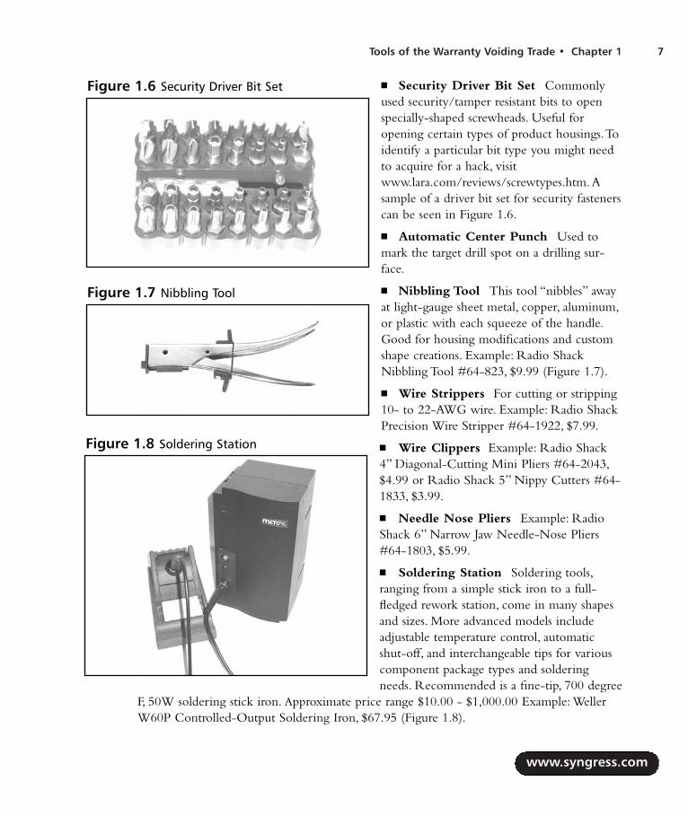
Nibbling Tool This tool “nibbles” awayat light-gauge sheet metal, copper, aluminum,or plastic with each squeeze of the handle.Good for housing modifications and customshape creations. Example: Radio ShackNibbling Tool #64-823, $9.99 (Figure 1.7).
Wire Strippers For cutting or stripping10- to 22-AWG wire. Example: Radio ShackPrecision Wire Stripper #64-1922, $7.99.
Wire Clippers Example: Radio Shack4” Diagonal-Cutting Mini Pliers #64-2043,$4.99 or Radio Shack 5” Nippy Cutters #64-1833, $3.99.
Needle Nose Pliers Example: RadioShack 6” Narrow Jaw Needle-Nose Pliers#64-1803, $5.99.
Soldering Station Soldering tools,ranging from a simple stick iron to a full-fledged rework station, come in many shapesand sizes. More advanced models includeadjustable temperature control, automaticshut-off, and interchangeable tips for variouscomponent package types and solderingneeds. Recommended is a fine-tip, 700 degree
F, 50W soldering stick iron. Approximate price range $10.00 - $1,000.00 Example: WellerW60P Controlled-Output Soldering Iron, $67.95 (Figure 1.8).
Figure 1.6 Security Driver Bit Set
Figure 1.7 Nibbling Tool
Figure 1.8 Soldering Station
287_HRD_HACK_01.qxd 1/11/04 10:56 AM Page 7

Soldering Accessories Essentialsoldering gear includes: solder,vacuum desoldering tool (a.k.a“solder sucker”), IC extraction tool,and ChipQuik SMD removal kit.Solder should be thin gauge (0.032”or 0.025” diameter) 60/40 Rosincore.The Desoldering Tool is amanual vacuum device that pulls uphot solder, useful for removing com-ponents from circuit boards (RadioShack #64-2098, $6.99).The ICExtraction Tool helps lift integratedcircuits from the board duringremoval/desoldering.The ChipQuik kit allows you to remove surface mount componentsquickly and easily. Some soldering accessories are shown in Figure 1.9.
Miscellaneous Cables This category includes cabling and wiring such as test leads, alli-gator clips, spools of wire, and computer cables.
Hardcore Hardware Hackers OnlyThese tools are for the hardcore hardware hacker, the best of the best, seriously dedicated to his orher trade. More specific tools exist as well, but generally the tools in this section will get you as far asyou need to go for a successful hardware hack of almost any type.
Jig Saw Essential power tool forcutting and shaping. Example:Bosch 1587AVSK Top-HandleJigsaw, $134.99.
Digital Multimeter (DMM)Commonly referred to as the “swissarmy knife” of electronics measure-ment tools (Figure 1.10).These are(usually) portable devices that pro-vide a number of precision measure-ment functions, including AC/DCvoltage, resistance, capacitance, cur-rent, and continuity. More advancedmodels also include frequency counters, graphical displays, and digital oscilloscope function-ality. Reliable meters have high DC input resistance (also called input impedance) of at least10Mohm. Approximate price range $20.00 - $500.00 Example: Fluke Model 111, $129.00.
www.syngress.com
8 Chapter 1 • Tools of the Warranty Voiding Trade
Figure 1.9 Soldering Accessories
Figure 1.10 Digital Multimeter
287_HRD_HACK_01.qxd 1/11/04 10:56 AM Page 8

Tools of the Warranty Voiding Trade • Chapter 1 9
www.syngress.com
Analog Multimeter The older siblingto the DMM.These devices provide measure-ments of AC/DC voltage, resistance, current,and continuity on an analog meter display.Useful for showing slow variations or unusualwave shapes that a DMM may not be able todetect or recognize. Example: Radio Shack 8-Range Multimeter #22-218A, $14.99.
Adjustable Power Supply Useful forany electronics-related design or hacking.Adjustable, linear, current-limited DC supply(Figure 1.11). Current limiting often preventsparts from failing (burning up or exploding)when there is a short circuit. Approximateprice range $100.00 - $1,000.00 Example:HP/Agilent Triple Output DC Power SupplyE3630A, $588.00.
Device Programmer Used to read andwrite memories (RAM, ROM, EPROM,EEPROM, Flash), microcontrollers, and pro-grammable logic devices (Figure 1.12).Extremely useful to extract program code andstored data. Approximate price range $10.00(home-built) - $2,500.00 Example: EE Tools’ChipMax, $345.00.
UV EPROM Eraser This tool is used toerase UV-erasable EPROM devices in amatter of minutes using high-intensity ultra-violet light (Figure 1.13). Approximate pricerange $25.00 - $250.00. Example: LogicalDevices Palm Erase, $59.95.
Figure 1.11 Adjustable Power Supply
Figure 1.12 Device Programmer
Figure 1.13 UV EPROM Eraser
287_HRD_HACK_01.qxd 1/11/04 10:56 AM Page 9
PCB Etching Kit These kits are used to create printed circuit boards for custom hard-ware hacks.This process is time consuming and uses hazardous chemicals. Radio Shack pro-vides a kit that contains two 3” x 4.5” copper-clad circuit boards, resist-ink pen, etching andstripping solutions, etching tank, 1/16” drill bit, polishing pad, and complete instructions.PCB etching materials can also be purchased separately at any electronics distributor.Example: Radio Shack PC Board Kit #276-1576, $14.99.
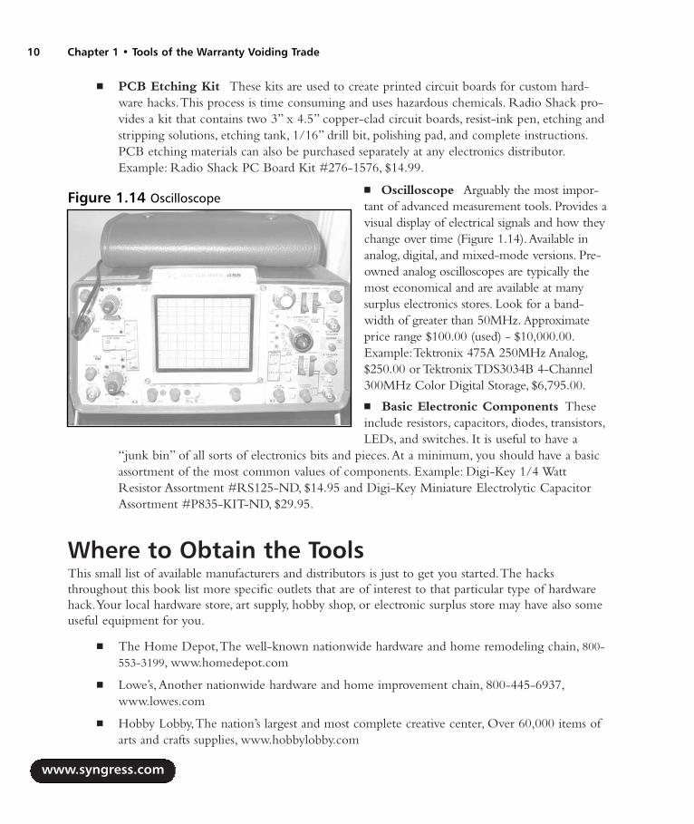
Oscilloscope Arguably the most impor-tant of advanced measurement tools. Provides avisual display of electrical signals and how theychange over time (Figure 1.14).Available inanalog, digital, and mixed-mode versions. Pre-owned analog oscilloscopes are typically themost economical and are available at manysurplus electronics stores. Look for a band-width of greater than 50MHz. Approximateprice range $100.00 (used) - $10,000.00.Example:Tektronix 475A 250MHz Analog,$250.00 or Tektronix TDS3034B 4-Channel300MHz Color Digital Storage, $6,795.00.
Basic Electronic Components Theseinclude resistors, capacitors, diodes, transistors,LEDs, and switches. It is useful to have a
“junk bin” of all sorts of electronics bits and pieces.At a minimum, you should have a basicassortment of the most common values of components. Example: Digi-Key 1/4 WattResistor Assortment #RS125-ND, $14.95 and Digi-Key Miniature Electrolytic CapacitorAssortment #P835-KIT-ND, $29.95.
Where to Obtain the ToolsThis small list of available manufacturers and distributors is just to get you started.The hacksthroughout this book list more specific outlets that are of interest to that particular type of hardwarehack.Your local hardware store, art supply, hobby shop, or electronic surplus store may have also someuseful equipment for you.
The Home Depot,The well-known nationwide hardware and home remodeling chain, 800-553-3199, www.homedepot.com
Lowe’s,Another nationwide hardware and home improvement chain, 800-445-6937,www.lowes.com
Hobby Lobby,The nation’s largest and most complete creative center, Over 60,000 items ofarts and crafts supplies, www.hobbylobby.com
www.syngress.com
10 Chapter 1 • Tools of the Warranty Voiding Trade
Figure 1.14 Oscilloscope
287_HRD_HACK_01.qxd 1/11/04 10:56 AM Page 10

McMaster-Carr,The leading supplier of all things mechanical including nuts, bolts, washers,lighting, fasteners, hand tools, and raw materials like metal, ceramic, rubber, plastic, felt, andglass, Over 400,000 products to choose from, 98 percent of those are in stock, 630-833-0300, www.mcmaster.com
Radio Shack, Well-known supplier of electronic tools, components, and various consumerelectronics, www.radioshack.com
Digi-Key, Major distributor for thousands of electronic components, 800-344-4539,www.digikey.com
Contact East, Leading product distributor for engineering tools, equipment, and materials,800-225-5370, www.contacteast.com
Test Equity, Specializing in the sale and rental of used electronic test/measurement equip-ment, 800-950-3457, www.testequity.com
www.syngress.com
Tools of the Warranty Voiding Trade • Chapter 1 11
287_HRD_HACK_01.qxd 1/11/04 10:56 AM Page 11

287_HRD_HACK_01.qxd 1/11/04 10:56 AM Page 12

ElectricalEngineering Basics
Fundamentals
Basic Device Theory
Soldering Techniques
Common Engineering Mistakes
Web Links and Other Resources
Note: Not all hacks in this book require electrical engineering.
Chapter 2
13
287_HRD_HACK_02.qxd 1/12/04 5:34 PM Page 13

IntroductionUnderstanding how hardware hacks work requires an introductory-level understanding of electronics.This chapter describes electronics fundamentals and the basic theory of the most common electroniccomponents. We also look at how to read schematic diagrams, identify components, proper solderingtechniques, and other engineering topics.
NEED TO KNOW…LIMITATIONS OF THIS CHAPTER
Engineering, like hardware hacking, is a skill that requires time and determination if youwant to be proficient in the field. There is a lot to discuss, but we have a limited amount ofspace. This chapter is not going to turn you into an electrical engineer or an electronics guru,but it will teach you enough about the basics of electronics and engineering that you canstart to find your way around. For more detail on the subject, see the suggested reading listat the end of this chapter.
FundamentalsIt is important to understand the core fundamentals of electronics before you venture into the detailsof specific components.This section provides a background on numbering systems, notation, and basictheory used in all facets of engineering.
Bits, Bytes, and NibblesAt the lowest level, electronic circuits and computers store information in binary format, which is abase-2 numbering system containing only 0 and 1, each known as a bit (derived from a combinationof the words binary, which is defined as something having two parts or components, and digit).Thecommon decimal numbering system that we use in everyday life is a base-10 system, which consistsof the digits 0 through 9.
Electrically, a 1 bit is generally represented by a positive voltage (5V, for example), and 0 is gener-ally represented by a zero voltage (or ground potential). However, many protocols and definitions mapthe binary values in different ways.
A group of 4 bits is a nibble (also known as a nybble), a group of 8 bits is a byte, and a group of 16bits is typically defined as a word (though a word is sometimes defined differently, depending on thesystem architecture you are referring to). Figure 2.1 shows the interaction of bits, nibbles, bytes, andwords.This visual diagram makes it easy to grasp the concept of how they all come together.
www.syngress.com
14 Chapter 2 • Electrical Engineering Basics
287_HRD_HACK_02.qxd 1/12/04 5:34 PM Page 14

Electrical Engineering Basics • Chapter 2 15
The larger the group of bits, the more information that can be represented.A single bit can repre-sent only two combinations (0 or 1).A nibble can represent 24 (or 16) possible combinations (0 to 15in decimal), a byte can represent 28 (or 256) possible combinations (0 to 255 in decimal), and a wordcan represent 216 (or 65,536) possible combinations (0 to 65,535 in decimal).
Hexadecimal format, also called hex, is commonly used in the digital computing world to representgroups of binary digits. It is a base-16 system in which 16 sequential numbers are used as base unitsbefore adding a new position for the next number (digits 0 through 9 and letters A through F). One hexdigit can represent the arrangement of 4 bits (a nibble).Two hex digits can represent 8 bits (a byte).Table2.1 shows equivalent number values in the decimal, hexadecimal, and binary number systems. Hex digitsare sometimes prefixed with 0x or $ to avoid confusion with other numbering systems.
Table 2.1 Number System Equivalents: Decimal, Binary, and Hexadecimal
Decimal Binary Hex
0 0 01 1 12 10 23 11 34 100 45 101 56 110 67 111 78 1000 89 1001 9
www.syngress.com
Figure 2.1 Breakdown of a 16-Bit Word into Bytes, Nibbles, and Bits
Word
Byte 1 (High) Byte 0 (Low)
Nibble 3 Nibble 2 Nibble 1 Nibble 0
Bit15
Bit14
Bit13
Bit12
Bit11
Bit10 Bit9 Bit
8 Bit7 Bit6 Bit5 Bit
4 Bit3 Bit2 Bit1 Bit
0
Continued
287_HRD_HACK_02.qxd 1/12/04 5:34 PM Page 15

Table 2.1 Number System Equivalents: Decimal, Binary, and Hexadecimal
Decimal Binary Hex
10 1010 A11 1011 B12 1100 C13 1101 D14 1110 E15 1111 F16 10000 1017 10001 1118 10010 1219 10011 1320 10100 1421 10101 1522 10110 1623 10111 1724 11000 1825 11001 1926 11010 1A27 11011 1B28 11100 1C29 11101 1D30 11110 1E31 11111 1F32 100000 20... ... ...63 111111 3F... ... ...127 1111111 7F... ... ...255 11111111 FF
American Standard Code for Information Interchange, or ASCII (pronounced ask-key), is thecommon code for storing characters in a computer system.The standard ASCII character set (seeTable 2.2) uses 1 byte to correspond to each of 128 different letters, numbers, punctuation marks, andspecial characters. Many of the special characters are holdovers from the original specification createdin 1968 and are no longer commonly used for their originally intended purpose. Only the decimal
www.syngress.com
16 Chapter 2 • Electrical Engineering Basics
287_HRD_HACK_02.qxd 1/12/04 5:34 PM Page 16

Electrical Engineering Basics • Chapter 2 17
values 0 through 127 are assigned, which is half of the space available in a byte.An extended ASCIIcharacter set uses the full range of 256 characters available in a byte.The decimal values of 128through 255 are assigned to represent other special characters that are used in foreign languages,graphics, and mathematics.
Table 2.2 The Standard ASCII Character Set
Hex Symbol Hex Symbol Hex Symbol Hex Symbol
0x00 NUL (null) 0x20 SP (space) 0x40 @ 0x60 `0x01 SOH (start of heading) 0x21 ! 0x41 A 0x61 a0x02 STX (start of text) 0x22 “ 0x42 B 0x62 b0x03 ETX (end of text) 0x23 # 0x43 C 0x63 c0x04 EOT (end of 0x24 $ 0x44 D 0x64 d
transmission)0x05 ENQ (enquiry) 0x25 % 0x45 E 0x65 e0x06 ACK (acknowledge) 0x26 & 0x46 F 0x66 f0x07 BEL (bell) 0x27 ‘ (apostrophe) 0x47 G 0x67 g0x08 BS (backspace) 0x28 ( 0x48 H 0x68 h0x09 HT (horizontal tab) 0x29 ) 0x49 I 0x69 i0x0A LF (line feed/new line) 0x2A * 0x4A J 0x6A j0x0B VT (vertical tab) 0x2B + 0x4B K 0x6B k0x0C FF (form feed) 0x2C , (comma) 0x4C L 0x6C l0x0D CR (carriage return) 0x2D - 0x4D M 0x6D m0x0E SO (shift out) 0x2E . (period) 0x4E N 0x6E n0x0F SI (shift in) 0x2F / 0x4F O 0x6F o0x10 DLE (data link escape) 0x30 0 0x50 P 0x70 p0x11 DC1 (device control 1) 0x31 1 0x51 Q 0x71 q0x12 DC2 (device control 2) 0x32 2 0x52 R 0x72 r0x13 DC3 (device control 3) 0x33 3 0x53 S 0x73 s0x14 DC4 (device control 4) 0x34 4 0x54 T 0x74 t0x15 NAK (negative 0x35 5 0x55 U 0x75 u
acknowledge)0x16 SYN (synchronous idle) 0x36 6 0x56 V 0x76 v0x17 ETB (end of 0x37 7 0x57 W 0x77 w
transmission block)0x18 CAN (cancel) 0x38 8 0x58 X 0x78 x0x19 EM (end of medium) 0x39 9 0x59 Y 0x79 y0x1A SUB (substitute) 0x3A : (colon) 0x5A Z 0x7A z
www.syngress.com
Continued
287_HRD_HACK_02.qxd 1/12/04 5:34 PM Page 17

Table 2.2 The Standard ASCII Character Set
Hex Symbol Hex Symbol Hex Symbol Hex Symbol
0x1B ESC (escape) 0x3B ; 0x5B [ 0x7B 0x1C FS (file separator) 0x3C < 0x5C \ 0x7C |0x1D GS (group separator) 0x3D = 0x5D ] 0x7D 0x1E RS (record separator) 0x3E > 0x5E ^ 0x7E ~0x1F US (unit separator) 0x3F ? 0x5F _ 0x7F Del (delete)
(underscore)
Reading SchematicsBefore we get into the theory of individual electronic components, it is important to learn how cir-cuit designs are drawn and described.A schematic is essentially an electrical road map. Reading basicschematics is a good skill to have, even if it is just to identify a particular component that needs to beremoved during a hack. Reading schematics is much easier than it may appear, and with practice itwill become second nature.
On a schematic, each component of the circuit is assigned its own symbol, unique to the type ofdevice that it is.The United States and Europe sometimes use different symbols, and there are evenmultiple symbols to represent one type of part.A resistor has its own special symbol, as does a capac-itor, a diode, or an integrated circuit.Think of schematic symbols as an alphabet for electronics.Table2.3 shows a selection of basic components and their corresponding designators and schematic sym-bols.This is by no means a complete list, and, as mentioned, a particular component type may haveadditional symbols that aren’t shown here.
A part designator is also assigned to each component and is used to distinguish between two partsof the same type and value.The designator is usually an alphanumeric character followed by a numer-ical value (R1, C4, or SW2, for example).The part designator and schematic symbol are used as a pairto define each discrete component of the circuit design.
Table 2.3 Designator and Schematic Symbols for Basic Electronic Components
Component Designator Symbol
Resistor R
Potentiometer (variable resistor) R
Capacitor (nonpolarized) C
www.syngress.com
18 Chapter 2 • Electrical Engineering Basics
Continued
287_HRD_HACK_02.qxd 1/12/04 5:34 PM Page 18

Table 2.3 Designator and Schematic Symbols for Basic Electronic Components
Component Designator Symbol
Capacitor (polarized) C
Diode D
LED D
Photodiode D
Transistor (NPN) Q
Transistor (PNP) Q
Crystal Y
Switch SW
Pushbutton switch SW
Speaker LS
Fuse F
Battery BT
www.syngress.com
Electrical Engineering Basics • Chapter 2 19
Continued
287_HRD_HACK_02.qxd 1/12/04 5:34 PM Page 19

Table 2.3 Designator and Schematic Symbols for Basic Electronic Components
Component Designator Symbol
None
Ground None
Figure 2.2 shows an example circuitusing some of the basic schematic symbols. Itdescribes a light-emitting diode (LED) pow-ered by a battery and controlled by a switch.When the switch is off, no current is able toflow from the battery through the rest of thecircuit, so the LED will not illuminate. Whenthe switch is enabled, current will flow fromthe battery through the current-limitingresistor and into the LED.The LED will illu-minate until the switch is turned off.
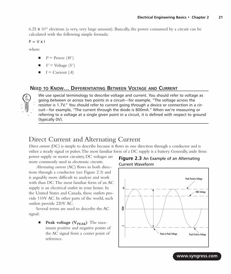
Voltage, Current, and ResistanceVoltage and current are the two staple quantities of electronics. Voltage, also known as a potential differ-ence, is the amount of work (energy) required to move a positive charge from a lower potential (amore negative point in a circuit) to higher potential (a more positive point in a circuit). Voltage canbe thought of as an electrical pressure or force and has a unit of volts (V). It is denoted with a symbolV, or sometimes E or U.
Current is the rate of flow (the quantity of electrons) passing through a given point. Current has aunit of amperes, or amps (A), and is denoted with a symbol of I. Kirchhoff ’s Current Law states thatthe sum of currents into a point equals the sum of the currents out of a point (corresponding to aconservation of charge).
Power is a “snapshot” of the amount of work being done at that particular point in time and has aunit of watts (W). One watt of power is equal to the work done in 1 second by 1 volt moving 1coulomb of charge. Furthermore, 1 coulomb per second is equal to 1 ampere.A coulomb is equal to
www.syngress.com
20 Chapter 2 • Electrical Engineering Basics
Figure 2.2 An Example Circuit: A Basic LEDwith a Current-Limiting Resistor and Switch
None
287_HRD_HACK_02.qxd 1/12/04 5:34 PM Page 20
6.25 x 10¹⁸ electrons (a very, very large amount). Basically, the power consumed by a circuit can becalculated with the following simple formula:
P = V x I
where
P = Power (W )
V = Voltage (V )
I = Current (A)
NEED TO KNOW… DIFFERENTIATING BETWEEN VOLTAGE AND CURRENT
We use special terminology to describe voltage and current. You should refer to voltage asgoing between or across two points in a circuit—for example, “The voltage across theresistor is 1.7V.” You should refer to current going through a device or connection in a cir-cuit—for example, “The current through the diode is 800mA.” When we’re measuring orreferring to a voltage at a single given point in a circuit, it is defined with respect to ground(typically 0V).
Direct Current and Alternating Current Direct current (DC) is simple to describe because it flows in one direction through a conductor and iseither a steady signal or pulses.The most familiar form of a DC supply is a battery. Generally, aside frompower supply or motor circuitry, DC voltages aremore commonly used in electronic circuits.
Alternating current (AC) flows in both direc-tions through a conductor (see Figure 2.3) andis arguably more difficult to analyze and workwith than DC.The most familiar form of an ACsupply is an electrical outlet in your home. Inthe United States and Canada, these outlets pro-vide 110V AC. In other parts of the world, suchoutlets provide 220V AC.
Several terms are used to describe the ACsignal:
Peak voltage (VPEAK) The max-imum positive and negative points ofthe AC signal from a center point ofreference.
www.syngress.com
Electrical Engineering Basics • Chapter 2 21
Figure 2.3 An Example of an AlternatingCurrent Waveform
Peak Positive Voltage
Peak Positive Voltage
RMS Voltage
Peak-to-Peak Voltage
0
+
–
287_HRD_HACK_02.qxd 1/12/04 5:34 PM Page 21
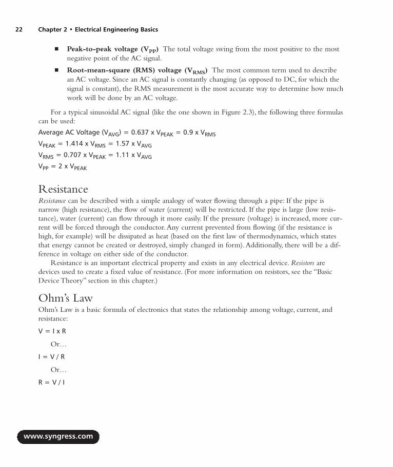
Peak-to-peak voltage (VPP) The total voltage swing from the most positive to the mostnegative point of the AC signal.
Root-mean-square (RMS) voltage (VRMS) The most common term used to describean AC voltage. Since an AC signal is constantly changing (as opposed to DC, for which thesignal is constant), the RMS measurement is the most accurate way to determine how muchwork will be done by an AC voltage.
For a typical sinusoidal AC signal (like the one shown in Figure 2.3), the following three formulascan be used:
Average AC Voltage (VAVG) = 0.637 x VPEAK = 0.9 x VRMS
VPEAK = 1.414 x VRMS = 1.57 x VAVG
VRMS = 0.707 x VPEAK = 1.11 x VAVG
VPP = 2 x VPEAK
ResistanceResistance can be described with a simple analogy of water flowing through a pipe: If the pipe isnarrow (high resistance), the flow of water (current) will be restricted. If the pipe is large (low resis-tance), water (current) can flow through it more easily. If the pressure (voltage) is increased, more cur-rent will be forced through the conductor.Any current prevented from flowing (if the resistance ishigh, for example) will be dissipated as heat (based on the first law of thermodynamics, which statesthat energy cannot be created or destroyed, simply changed in form).Additionally, there will be a dif-ference in voltage on either side of the conductor.
Resistance is an important electrical property and exists in any electrical device. Resistors aredevices used to create a fixed value of resistance. (For more information on resistors, see the “BasicDevice Theory” section in this chapter.)
Ohm’s LawOhm’s Law is a basic formula of electronics that states the relationship among voltage, current, andresistance:
V = I x R
Or…
I = V / R
Or…
R = V / I
www.syngress.com
22 Chapter 2 • Electrical Engineering Basics
287_HRD_HACK_02.qxd 1/12/04 5:34 PM Page 22

Where…
V = Voltage (V )
I = Current (A)
R = Resistance (in ohms, designated with the omega symbol, Ω)
Basic Device TheoryThis section explores the basic device theory of the five most common electronic components: resis-tors, capacitors, diodes, transistors, and integrated circuits. Understanding the functionality of theseparts is essential to any core electronics knowledge and will prove useful in designing or reverse-engi-neering products.
ResistorsResistors are used to reduce the amount of current flowing through a point in a system. Resistors aredefined by three values:
Resistance (Ω)
Heat dissipation (in watts, W )
Manufacturing tolerance (%)
A sampling of various resistor types is shownin Figure 2.4. Resistors are not polarized,meaning that they can be inserted in either ori-entation with no change in electrical function.
The resistance value of a resistor is indicatedby an industry-standard code of four or five col-ored bands (see Figure 2.5).The colors areprinted directly onto the resistor. For example,any resistor with a black multiplier band fallsbetween 10 and 99 ohms in value, brown desig-nates a value between 100 and 999 ohms, redindicates a value from 1000 to 9999 ohms (alsoexpressed as 1.0K to 9.9K), and so on.The man-ufacturing tolerance of the resistor, which is theallowable skew of a resistor value from its idealrated value, is specified by another colored band.
www.syngress.com
Electrical Engineering Basics • Chapter 2 23
Figure 2.4 Various Resistor Types
287_HRD_HACK_02.qxd 1/12/04 5:34 PM Page 23

A resistor’s internal composition can con-sist of many different materials, but typicallyone of three are used: carbon, metal film, orwire-wound.The material is usually wrappedaround a core, with the wrapping type andlength corresponding to the resistor value.The carbon-filled resistor, used in most gen-eral-purpose applications such as current lim-iting and nonprecise circuits, allows a +/-5percent tolerance on the resistor value. Metalfilm resistors are for more precise applicationssuch as amplifiers, power supplies, and sensi-tive analog circuitry; they usually allow a +/-1 or 2 percent tolerance. Wire-woundresistors can also be very accurate.
When resistors are used in series in a cir-cuit (see Figure 2.6), their resistance valuesare additive, meaning that you simply add thevalues of the resistors in series to obtain thetotal resistance. For example, if R1 is 220ohm and R2 is 470 ohm, the overall resis-tance will be 690 ohm.
Parallel circuits always provide alternativepathways for current flow, although thevoltage across the components in parallel isthe same. When resistors are used in parallel(see Figure 2.7), a simple equation is used tocalculate the overall resistance:
1 / RTOTAL = (1 / R1) + (1 / R2) + ...
This same formula can be extended forany number of resistors used in parallel. Forexample, if R1 is 220 ohm and R2 is 470ohm, the overall resistance will be 149.8ohm.
For only two resistors in parallel, an alter-nate formula can be used:
RTOTAL = (R1 x R2) / (R1 + R2)
Carbon and metal film resistors typically come in wattage values of 1/16W, 1/8W, 1/4W, 1/2Wand 1W.This corresponds to how much power they can safely dissipate.The most commonly used
www.syngress.com
24 Chapter 2 • Electrical Engineering Basics
Figure 2.5 Resistor Color Code Chart
Figure 2.6 Resistors in Series
Figure 2.7 Resistors in Parallel
287_HRD_HACK_02.qxd 1/12/04 5:34 PM Page 24
resistors are 1/4W and 1/2W. For large current applications, wire-wound resistors are typically usedbecause they can support wattages greater than 1W.The wattage of the resistor usually corresponds toits physical size and surface area. For most consumer electronics, resistors greater than 1W are typicallynot used.To calculate the required wattage value for your application, use the following equation:
P = V x I
Or…
P = I2 x R
Where…
P = Power (W )
V = Voltage across the resistor (V )
I = Current flowing through the resistor (A)
R = Resistance value (Ω)
CapacitorsA capacitor’s primary function is to store electrical energy in the form of electrostatic charge.Capacitors are an essential component used in almost any circuit design. Consider a simple exampleof a water tower, which stores water (the charge): When the water system (or circuit) produces morewater than a town or building needs, the excess is stored in the water tower (or capacitor).At times ofhigh demand, when additional water is needed, the excess water (the charge) flows out of the watertower to keep the pressure up.
A capacitor is usually implemented for one of three uses:
To store a charge Typically used for high-speed or high-power applications, such as alaser or a camera flash.The capacitor will be fully charged by the circuit in a fixed length oftime, and then all its stored energy will be released and used almost instantaneously, just likethe water tower example previously described.
To block DC voltage If a DC voltage source is connected in series to a capacitor, thecapacitor will instantaneously charge and no DC voltage will pass into the rest of the circuit.However, an AC signal flows through a capacitor unimpeded because the capacitor willcharge and discharge as the AC fluctuates, making it appear that the alternating current isflowing.
To eliminate ripples Useful for filtering, signal processing, and other analog designs. If aline carrying DC voltage has ripples or spikes in it, also known as “noise,” a capacitor cansmooth or “clean” the voltage to a more steady value by absorbing the peaks and filling inthe valleys of the noisy DC signal.
Capacitors are constructed of two metal plates separated by a dielectric.The dielectric is any mate-rial that does not conduct electricity, and it varies for different types of capacitors. It prevents the
www.syngress.com
Electrical Engineering Basics • Chapter 2 25
287_HRD_HACK_02.qxd 1/12/04 5:34 PM Page 25

plates from touching each other. Electrons are stored on one plate of the capacitor and they dischargethrough the other. Consider lightning in the sky as a real-world example of a capacitor: One plate isformed by the clouds, the other plate is formed by the earth’s ground, and the dielectric is the air inbetween.The lightning is the charge releasing between the two plates.
Depending on their construction, capacitors are either polarized, meaning that they exhibitvarying characteristics based on the direction they are used in a circuit, or nonpolarized, meaning thatthey can be inserted in either orientation with no change in electrical function.A sampling of variousresistor types is shown in Figures 2.8 and 2.9.
Capacitors have a unit of farad (F).A 1 farad capacitor can store 1 coulomb of charge at 1 volt(equal to 1 amp-second of electrons at 1 volt).A single farad is a very large amount. Most capacitorsstore a miniscule amount of charge and are usually denoted in uF (microfarads, 10-6 x F) or pF (pico-farads, 10-12 x F).The physical size of the capacitor is usually related to the dielectric material and theamount of charge that the capacitor can hold.
Unlike resistors, capacitors do not use a color code for value identification.Today, most mono-lithic and ceramic capacitors are marked with a three-number code called an IEC marking (see Figure2.10).The first two digits of the code indicate a numerical value; the last digit indicates a multiplier.Electrolytic capacitors are always marked in uF.These devices are polarized and must be oriented cor-rectly during installation. Polarized devices have a visible marking denoting the negative side of thedevice. (In the case of surface-mount capacitors, the marking is on the positive side.) There may beadditional markings on the capacitor (sometimes just a single character); these usually denote thecapacitor’s voltage rating or manufacturer.
www.syngress.com
26 Chapter 2 • Electrical Engineering Basics
Figure 2.8 Various NonpolarizedCapacitor Types (Ceramic Disc andMultilayer)
Figure 2.9 Various Polarized CapacitorTypes (Electrolytic and Tantalum)
287_HRD_HACK_02.qxd 1/12/04 5:34 PM Page 26

The calculations to deter-mine effective capacitance ofcapacitors in series and parallelare essentially the reverse ofthose used for resistors. Whencapacitors are used in series (seeFigure 2.11), a simple equation isused to calculate the effectivecapacitance:
1 / CTOTAL = (1 / C1) + (1 / C2) + ...
This same formula can be extended for any number of capacitors used in series. For example, ifC1 is 100uF and C2 is 47uF, the overall capacitance will be 31.9uF.
For only two capacitors in series, an alternate formula can be used:
CTOTAL = (C1 x C2) / (C1 + C2)
When using capacitors in series, you storeeffectively less charge than you would by usingeither one alone in the circuit.The advantage tocapacitors in series is that it increases the max-imum working voltage of the devices.
When capacitors are used in parallel in a cir-cuit (see Figure 2.12), their effective capacitance isadditive, meaning that you simply add the valuesof the capacitors in parallel to obtain the totalcapacitance. For example, if C1 is 100uF and C2 is47uF, the overall capacitance will be 147uF.
Capacitors are often used in combination withresistors in order to control their charge and dis-charge time. Resistance directly affects the timerequired to charge or discharge a capacitor (thelarger the resistance, the longer the time).
Figure 2.13 shows a simple RC circuit.Thecapacitor will charge as shown by the curve inFigure 2.14.The amount of time for the capacitorto become fully charged in an RC circuit dependson the values of the capacitor and resistor in thecircuit.
www.syngress.com
Electrical Engineering Basics • Chapter 2 27
Figure 2.10 Examples of Some Capacitor IEC Markings
Figure 2.11 Capacitors in Series
Figure 2.12 Capacitors in Parallel
287_HRD_HACK_02.qxd 1/12/04 5:34 PM Page 27

The variable τ (called the time constant)is used to define the time it takes for thecapacitor to charge to 63.2 percent of itsmaximum capacity.The time constant can becalculated by the following formula:
τ = R x CWhere…
τ = Time constant (seconds)
C = Capacitance (F )
R = Resistance (Ω)
A capacitor reaches 63.2 percent of itscharge in one-fifth the time it takes tobecome fully charged. Capacitors in actualapplications are usually not charged to theirfull capacity because it takes too long.
DiodesIn the most basic sense, diodes pass current inone direction while blocking it from theother.This allows for their use in rectifyingAC into DC, filtering, limiting the range of asignal (known as a diode clamp), and as“steering diodes,” in which diodes are used toallow voltage to be applied to only one partof the circuit.
Most diodes are made with semicon-ductor materials such as silicon, germanium,or selenium. Diodes are polarized, meaningthat they exhibit varying characteristicsdepending on the direction they are used in acircuit. When current is flowing through thediode in the direction shown in Figure 2.15(from anode, left, to cathode, right), the diodeappears as a short circuit. When current triesto pass in the opposite direction, the diodeexhibits a high resistance, preventing the cur-rent from flowing.
www.syngress.com
28 Chapter 2 • Electrical Engineering Basics
Figure 2.13 A Simple RC Circuit to Charge aCapacitor
Figure 2.14 Capacitor-Charging Curve
V
V1
63%
0tτ
Figure 2.15 Various Diode Types ShowingDirection of Current Flow
287_HRD_HACK_02.qxd 1/12/04 5:34 PM Page 28

Diodes come in many types and sizes, each with varying electrical properties.You need to con-sider characteristics such as breakdown voltage, forward voltage, forward current, and reverse recoverytime when designing with diodes or replacing one in a circuit:
Breakdown/reverse voltage (VR), also known as the peak inverse voltage (PIV), is the max-imum voltage you can apply across a diode in the reverse direction and still have it blockconduction. If this voltage is exceeded, the diode goes into “avalanche breakdown” and con-ducts current, essentially rendering the diode useless (unless it’s a Zener diode, which isdesigned to operate in this breakdown region).
Forward voltage (VF) is the voltage drop across the diode.This usually corresponds to theforward current (the greater the current flowing through the diode, the larger the voltagedrop).Typical forward voltage of a general-purpose diode is between 0.5V and 0.8V at10mA.
Forward current (IF) is the maximum current that can flow through the diode. If currentflowing through the diode is more than it can handle, it overheats and can quickly meltdown and cause a short circuit.
Reverse recovery time (TRR) isthe time it takes a diode to go fromforward conduction to reverseblocking (think of a revolving doorthat goes in both directions and thepeople coming in and going outacting as the current). If theturnaround time is too slow, currentwill flow in the reverse directionwhen the polarity changes andcause the diode junction to heat upand possibly fail.This is primarily ofconcern for AC-rectifying circuitscommonly used in power supplies.
Figure 2.16 shows the diode V-I curve, astandard curve that describes the relationshipbetween current and voltage with respect to adiode.
In normal forward bias operation (shown on the right side of the graph), the diode begins toconduct and act as a short circuit after the forward voltage drop is met (usually between 0.5V and0.8V). In reverse bias operation (shown on the left side of the graph), reverse current is generallymeasured in the nA range (an extremely small measure of current). When the diode is reverse biased,current is essentially prevented from flowing in that direction, with the exception of a very smallleakage current.The point at which the diode begins its avalanche breakdown is called “the knee,” as
www.syngress.com
Electrical Engineering Basics • Chapter 2 29
Figure 2.16 The Diode V-I Curve
Forward Voltage V
I
Reverse bias mode
Breakdown voltage“The knee”
Forward bias mode
287_HRD_HACK_02.qxd 1/12/04 5:34 PM Page 29
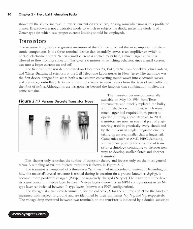
shown by the visible increase in reverse current on the curve, looking somewhat similar to a profile ofa knee. Breakdown is not a desirable mode to which to subject the diode, unless the diode is of aZener type (in which case proper current limiting should be employed).
TransistorsThe transistor is arguably the greatest invention of the 20th century and the most important of elec-tronic components. It is a three-terminal device that essentially serves as an amplifier or switch tocontrol electronic current. When a small current is applied to its base, a much larger current isallowed to flow from its collector.This gives a transistor its switching behavior, since a small currentcan turn a larger current on and off.
The first transistor was demonstrated on December 23, 1947, by William Shockley, John Bardeen,and Walter Brattain, all scientists at the Bell Telephone Laboratories in New Jersey.The transistor wasthe first device designed to act as both a transmitter, converting sound waves into electronic waves,and a resistor, controlling electronic current.The name transistor comes from the trans of transmitter andthe sistor of resistor.Although its use has gone far beyond the function that combination implies, thename remains.
The transistor became commerciallyavailable on May 10, 1954 from TexasInstruments, and quickly replaced the bulkyand unreliable vacuum tubes, which weremuch larger and required more power tooperate. Jumping ahead 50 years, to 2004,transistors are now an essential part of engi-neering, used in practically every circuit andby the millions in single integrated circuitstaking up an area smaller than a fingernail.Companies such as AMD, NEC, Samsung,and Intel are pushing the envelope of tran-sistor technology, continuing to discover newways to develop smaller, faster, and cheapertransistors.
This chapter only scratches the surface of transistor theory and focuses only on the most generalterms.A sampling of various discrete transistors is shown in Figure 2.17.
The transistor is composed of a three-layer “sandwich” of semiconductor material. Depending onhow the material’s crystal structure is treated during its creation (in a process known as doping), itbecomes more positively charged (P-type) or negatively charged (N-type).The transistor’s three-layerstructure contains a P-type layer between N-type layers (known as an NPN configuration) or an N-type layer sandwiched between P-type layers (known as a PNP configuration).
The voltages at a transistor terminal (C for the collector, E for the emitter, and B for the base) aremeasured with respect to ground and are identified by their pin names, VC, VE, and VB, respectively.The voltage drop measured between two terminals on the transistor is indicated by a double-subscript
www.syngress.com
30 Chapter 2 • Electrical Engineering Basics
Figure 2.17 Various Discrete Transistor Types
287_HRD_HACK_02.qxd 1/12/04 5:35 PM Page 30

(for example, VBE corresponds to the voltagedrop from the base to the emitter). Figure2.18 shows the typical single NPN and PNPschematic symbols and notations.
A trick to help you remember which dia-gram corresponds to which transistor type isto think of NPN as meaning “not pointingin” (in reference to the base-emitter diode).With that said, the other transistor is obvi-ously the PNP type.
An NPN transistor has four propertiesthat must be met (the properties for the PNPtype are the same, except the polarities arereversed):
1. The collector must be more positivethan the emitter.
2. The base-emitter and base-collectorcircuits look like two diodes back toback (see Figure 2.19). Normallythe base-emitter diode is con-ducting (with a forward voltagedrop, VBE, of approximately 0.7V)and the base-collector diode isreverse-biased.
3. Each transistor has maximum valuesof IC, IB, and VCE that cannot beexceeded without risk of damagingthe device. Power dissipation andother limits specified in the manu-facturer’s data sheet should also beobeyed.
4. The current flowing from collectorto emitter (IC) is roughly propor-tional to the current input to thebase (IB), shown in Figure 2.20, andcan be calculated with the followingformula:
IC = hFE x IBor
IC = β x IB
www.syngress.com
Electrical Engineering Basics • Chapter 2 31
Figure 2.18 NPN (Left) and PNP (Right)Transistor Diagrams
Figure 2.19 Diode Representation of aTransistor, NPN (Left) and PNP (Right)
Figure 2.20 NPN Transistor Characteristic Curve
287_HRD_HACK_02.qxd 1/12/04 5:35 PM Page 31
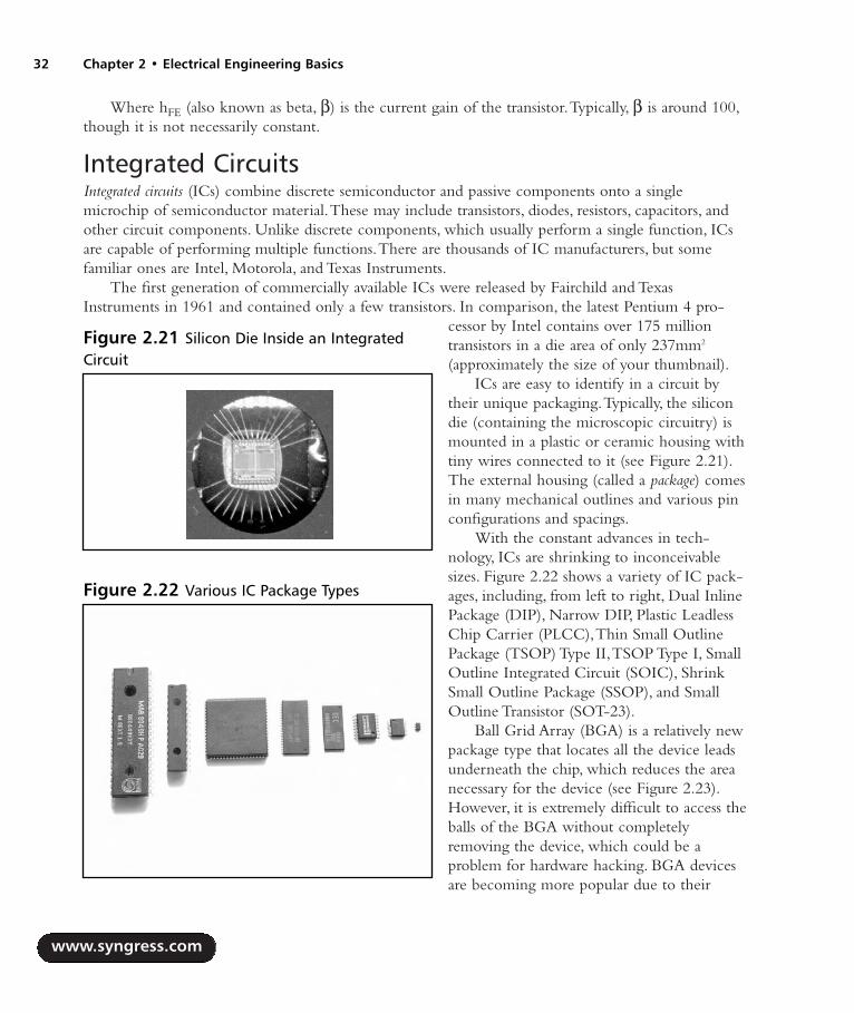
Where hFE (also known as beta, β) is the current gain of the transistor.Typically, β is around 100,though it is not necessarily constant.
Integrated CircuitsIntegrated circuits (ICs) combine discrete semiconductor and passive components onto a singlemicrochip of semiconductor material.These may include transistors, diodes, resistors, capacitors, andother circuit components. Unlike discrete components, which usually perform a single function, ICsare capable of performing multiple functions.There are thousands of IC manufacturers, but somefamiliar ones are Intel, Motorola, and Texas Instruments.
The first generation of commercially available ICs were released by Fairchild and TexasInstruments in 1961 and contained only a few transistors. In comparison, the latest Pentium 4 pro-
cessor by Intel contains over 175 milliontransistors in a die area of only 237mm2
(approximately the size of your thumbnail).ICs are easy to identify in a circuit by
their unique packaging.Typically, the silicondie (containing the microscopic circuitry) ismounted in a plastic or ceramic housing withtiny wires connected to it (see Figure 2.21).The external housing (called a package) comesin many mechanical outlines and various pinconfigurations and spacings.
With the constant advances in tech-nology, ICs are shrinking to inconceivablesizes. Figure 2.22 shows a variety of IC pack-ages, including, from left to right, Dual InlinePackage (DIP), Narrow DIP, Plastic LeadlessChip Carrier (PLCC),Thin Small OutlinePackage (TSOP) Type II,TSOP Type I, SmallOutline Integrated Circuit (SOIC), ShrinkSmall Outline Package (SSOP), and SmallOutline Transistor (SOT-23).
Ball Grid Array (BGA) is a relatively newpackage type that locates all the device leadsunderneath the chip, which reduces the areanecessary for the device (see Figure 2.23).However, it is extremely difficult to access theballs of the BGA without completelyremoving the device, which could be aproblem for hardware hacking. BGA devicesare becoming more popular due to their
www.syngress.com
32 Chapter 2 • Electrical Engineering Basics
Figure 2.21 Silicon Die Inside an IntegratedCircuit
Figure 2.22 Various IC Package Types
287_HRD_HACK_02.qxd 1/12/04 5:35 PM Page 32
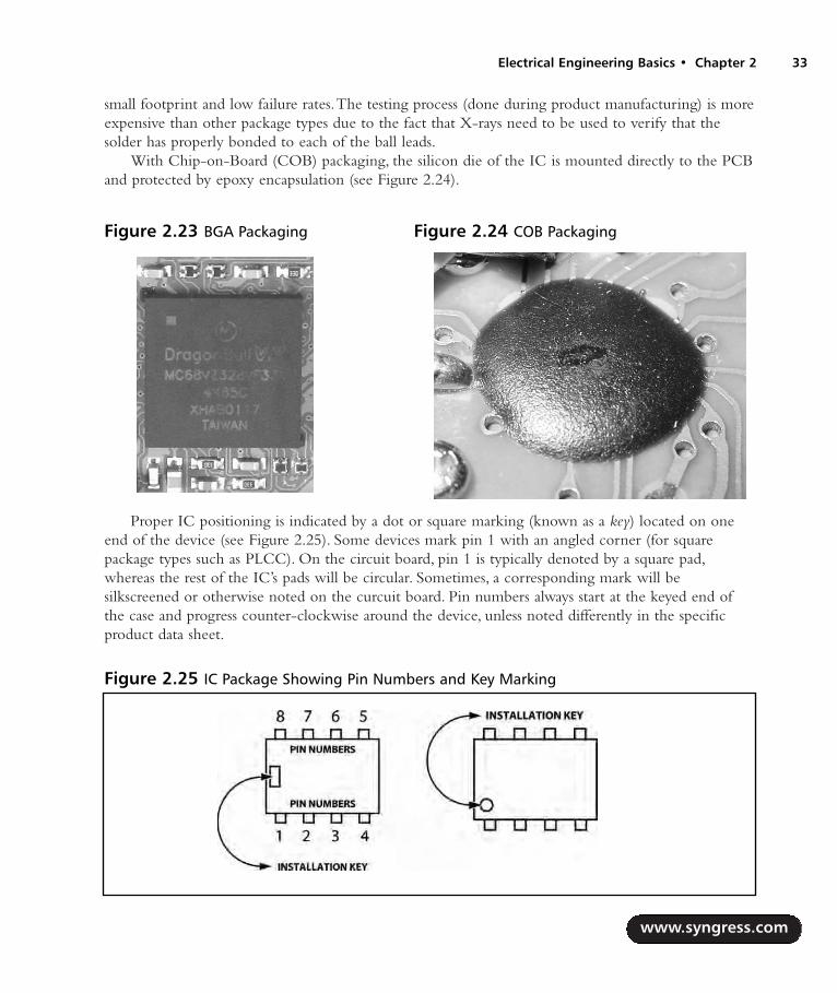
small footprint and low failure rates.The testing process (done during product manufacturing) is moreexpensive than other package types due to the fact that X-rays need to be used to verify that thesolder has properly bonded to each of the ball leads.
With Chip-on-Board (COB) packaging, the silicon die of the IC is mounted directly to the PCBand protected by epoxy encapsulation (see Figure 2.24).
Proper IC positioning is indicated by a dot or square marking (known as a key) located on oneend of the device (see Figure 2.25). Some devices mark pin 1 with an angled corner (for squarepackage types such as PLCC). On the circuit board, pin 1 is typically denoted by a square pad,whereas the rest of the IC’s pads will be circular. Sometimes, a corresponding mark will besilkscreened or otherwise noted on the curcuit board. Pin numbers always start at the keyed end ofthe case and progress counter-clockwise around the device, unless noted differently in the specificproduct data sheet.
www.syngress.com
Electrical Engineering Basics • Chapter 2 33
Figure 2.23 BGA Packaging Figure 2.24 COB Packaging
Figure 2.25 IC Package Showing Pin Numbers and Key Marking
287_HRD_HACK_02.qxd 1/12/04 5:35 PM Page 33

Soldering TechniquesSoldering is an art form that requires proper technique. With practice, you will become comfortableand experienced with it.The two key parts of soldering are good heat distribution and cleanliness ofthe soldering surface and component. In the most basic sense, soldering requires a soldering iron andsolder.There are many shapes and sizes of tools to choose from; you can find more details in Chapter1 “Tools of the Warranty Voiding Trade.”This section uses hands-on examples to demonstrate propersoldering and desoldering techniques.
WARNING: PERSONAL INJURY
Improper handling of the soldering iron can lead to burns or other physical injuries. Wearsafety goggles and other protective clothing when working with solder tools. With tempera-tures hovering around 700 degrees F, the tip of the soldering iron, molten solder, and fluxcan quickly sear through clothing and skin. Keep all soldering equipment away fromflammable materials and objects. Be sure to turn off the iron when it is not in use and storeit properly in its stand.
Hands-On Example: Soldering a Resistor to a Circuit BoardThis simple example shows the step-by-step process to solder a through-hole component to a printedcircuit board (PCB). We use a piece of prototype PCB and a single resistor (see Figure 2.26). Before
you install and solder a part, inspect the leadsor pins for oxidation. If the metal surface isdull, sand with fine sandpaper until shiny. Inaddition, clean the oxidation and excesssolder from the soldering iron tip to ensuremaximum heat transfer.
Bend and insert the component leadsinto the desired holes on the PCB. Flip theboard to the other side. Slightly bend the leadyou will be soldering to prevent the compo-nent from falling out when the board isturned upside down (see Figure 2.27).
www.syngress.com
34 Chapter 2 • Electrical Engineering Basics
Figure 2.26 Prototype PCB and Resistor Usedin the Example
287_HRD_HACK_02.qxd 1/12/04 5:35 PM Page 34
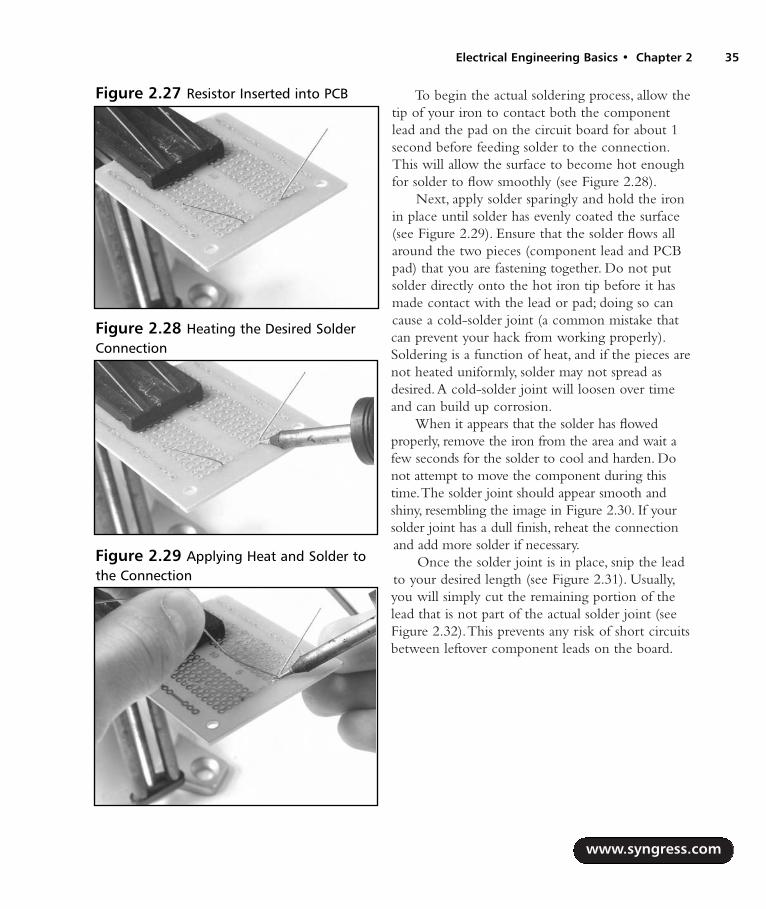
To begin the actual soldering process, allow thetip of your iron to contact both the componentlead and the pad on the circuit board for about 1second before feeding solder to the connection.This will allow the surface to become hot enoughfor solder to flow smoothly (see Figure 2.28).
Next, apply solder sparingly and hold the ironin place until solder has evenly coated the surface(see Figure 2.29). Ensure that the solder flows allaround the two pieces (component lead and PCBpad) that you are fastening together. Do not putsolder directly onto the hot iron tip before it hasmade contact with the lead or pad; doing so cancause a cold-solder joint (a common mistake thatcan prevent your hack from working properly).Soldering is a function of heat, and if the pieces arenot heated uniformly, solder may not spread asdesired.A cold-solder joint will loosen over timeand can build up corrosion.
When it appears that the solder has flowedproperly, remove the iron from the area and wait afew seconds for the solder to cool and harden. Donot attempt to move the component during thistime.The solder joint should appear smooth andshiny, resembling the image in Figure 2.30. If yoursolder joint has a dull finish, reheat the connectionand add more solder if necessary.
Once the solder joint is in place, snip the leadto your desired length (see Figure 2.31). Usually,you will simply cut the remaining portion of thelead that is not part of the actual solder joint (seeFigure 2.32).This prevents any risk of short circuitsbetween leftover component leads on the board.
www.syngress.com
Electrical Engineering Basics • Chapter 2 35
Figure 2.27 Resistor Inserted into PCB
Figure 2.28 Heating the Desired SolderConnection
Figure 2.29 Applying Heat and Solder tothe Connection
287_HRD_HACK_02.qxd 1/12/04 5:35 PM Page 35

Every so often during any soldering pro-cess, use a wet sponge to lightly wipe theexcess solder and burned flux from the tip ofyour soldering iron.This allows the tip to stayclean and heat properly. Proper maintenanceof your soldering equipment will also increaseits life span.
Desoldering TipsDesoldering, or removing a soldered compo-nent from a circuit board, is typically moretricky than soldering, because you can easilydamage the device, the circuit board, or sur-rounding components.
For standard through-hole components,first grasp the component with a pair ofneedle-nose pliers. Heat the pad beneath thelead you intend to extract and pull gently.The lead should come out. Repeat for the other lead. If solderfills in behind the lead as you extract it, use a spring-loaded solder sucker to remove the excess solder.
For through-hole ICs or multipin parts, use a solder sucker or desoldering braid to remove excessfrom the hole before attempting to extract the part.You can use a small flat-tip screwdriver or ICextraction tool to help loosen the device from the holes. Be careful to not overheat components, sincethey can become damaged and may fail during operation. If a component is damaged during extrac-tion, simply replace it with a new part. For surface mount devices (SMDs) with more than a few pins,the easiest method to remove the part is by using the ChipQuik SMD Removal Kit, as shown in thefollowing step-by-step example. Removal of SMD and BGA devices is normally accomplished withspecial hot-air rework stations.These stations provide a directed hot-air stream used with specific noz-
www.syngress.com
36 Chapter 2 • Electrical Engineering Basics
Figure 2.30 Successful Solder JointFigure 2.31 Snipping Off the RemainingComponent Lead
Figure 2.32 Completed Soldering Example
287_HRD_HACK_02.qxd 1/12/04 5:35 PM Page 36

zles, depending on the type of device to be removed.The hot air can flow freely around and underthe device, allowing the device to be removed with minimal risk of overheating. Rework stations aretypically priced beyond the reach of hobbyist hardware hackers, and the ChipQuik kit works quitewell as a low-cost alternative.
Hands-On Example: SMD Removal Using ChipQuikThe ChipQuik SMD Removal Kit (www.chipquik.com) allows you to quickly and easily removesurface mount components such as PLCC, SOIC,TSOP, QFP, and discrete packages.The primarycomponent of the kit is a low-melting temperature solder (requiring less than 300 degrees F) thatreduces the overall melting temperature of the solder on the SMD pads. Essentially, this enables you tojust lift the part right off the PCB.
WARNING: HARDWARE HARM
Please read through this example completely before attempting SMD removal on an actualdevice. When removing the device, be careful to not scratch or damage any of the sur-rounding components or pull up any PCB traces. Using the ChipQuik SMD rework packagemakes it easy to remove the fine-pitch memory device. After following the instructions onthe package (which consists of simply applying a standard no-clean flux to the SMD pins andthen applying a low-melting-point solder), you can easily remove the surface mount partfrom the board. Use rubbing alcohol to remove any residual from the solder pads. Verify thatthe solder pads are clean and free from cuts or solder jumps before proceeding to the nextstep of the hack.
Figure 2.33 shows the contents of thebasic ChipQuik SMD Removal Kit, from topto bottom: alcohol pads for cleaning the cir-cuit board after device removal, the speciallow-melting temperature alloy, standard no-clean flux, and application syringe.
www.syngress.com
Electrical Engineering Basics • Chapter 2 37
Figure 2.33 ChipQuik SMD Removal KitContents
287_HRD_HACK_02.qxd 1/12/04 5:35 PM Page 37

Figure 2.34 shows the circuit boardbefore the SMD part removal. Our targetdevice to remove is the largest device on theboard, the Winbond WTS701EM/T 56-pinTSOP IC.
The first step is to assemble the syringe,which contains the no-clean flux. Simplyinsert the plunger into the syringe and pushdown to dispense the compound (see Figure2.35).The flux should be applied evenlyacross all the pins on the package you will beremoving (see Figure 2.36). Flux is a chemicalcompound used to assist in the soldering orremoval of electronic components or othermetals. It has three primary functions:
1. Cleans metals surfaces to assist theflow of filler metals (solder) overbase metals (device pins)
2. Assists with heat transfer from heatsource (soldering iron) to metal sur-face (device pins)
3. Helps in the removal of surfacemetal oxides (created by oxygen inthe air when the metal reaches hightemperatures)
Once the flux is evenly spread over thepins of the target device, the next step is toapply the special ChipQuik alloy to thedevice (see Figure 2.37).This step is just likesoldering:Apply heat to the pins of thedevice and the alloy at the same time.Thealloy has a melting point of approximately300 degrees F, which is quite low.You shouldnot have to heat the alloy with the solderingiron for very long before it begins to melt.The molten alloy should flow around andunder the device pins (see Figure 2.38).
www.syngress.com
38 Chapter 2 • Electrical Engineering Basics
Figure 2.34 Circuit Board Before Part Removal
Figure 2.35 Applying Flux to the Leads
Figure 2.36 Chip with Flux Applied
287_HRD_HACK_02.qxd 1/12/04 5:35 PM Page 38

Starting at one end of the device, simply heat andapply the alloy. Repeat for the other side(s) of thedevice.The flux will help with ensuring a niceflow of the alloy onto the device pins. Ensure thatthe alloy has come in contact with every single pinby gently moving the soldering iron around theedges of the device.Avoid touching nearby com-ponents on the PCB with the soldering iron.
Now that the alloy has been properly appliedto all pins of the device, it is time to remove thedevice from the board.After making sure that thealloy is still molten by reheating all of it with thesoldering iron, gently slide the component off theboard (see Figure 2.39).You can use a small jew-eler’s flathead screwdriver to help with the task. Ifthe device is stuck, reheat the alloy and wiggle thepart back and forth to help the alloy flow under-neath the pads of the device and loosen the con-nections.
The final step in the desoldering process is toclean the circuit board.This step is importantbecause it will remove any impurities left behindfrom the ChipQuik process and leave you readyfor the next step in your hardware hack.
First, use the soldering iron to remove anystray alloy left on the device pads or anywhere elseon the circuit board. Next, apply a thin, even layerof flux to all of the pads that the device was justsoldered to. Use the included alcohol swab or aflux remover spray to remove the flux and cleanthe area (see Figure 2.40).
www.syngress.com
Electrical Engineering Basics • Chapter 2 39
Figure 2.37 Applying Heat and Alloy tothe Leads
Figure 2.38 Chip with Alloy Applied
Figure 2.39 Removing the Device fromthe Board
287_HRD_HACK_02.qxd 1/12/04 5:35 PM Page 39

The desoldering process is now complete.The surface mount device has been removed and the cir-cuit board cleaned (see Figure 2.41). If you intend to reuse the device you just removed, use the sol-dering iron to remove any stray alloy or solder left over on and in between the pins and ensure there areno solder bridges between pins. If you do not want to reuse the device, simply throw it away.
Common Engineering MistakesDuring engineering design and debugging, you should remember the important maxim K.I.S.S.—orKeep It Simple, Stupid—at all times. It can be frustrating to troubleshoot a problem for hours or days onend and then discover the cause was a simple oversight.The most common engineering mistakes forhardware hacking are listed here.Although there are hundreds of other simple mistakes that can cause anengineer to quickly lose his or her hair, this list should get you started and keep you on your toes.
Faulty solder connections After soldering, inspect the connections for cold-solder jointsand solder bridges. Cold-solder joints happen when you don’t fully heat the connection orwhen metallic corrosion and oxide contaminate a component lead or pad. Cold-solderjoints are the most common mistake for amateur and hobbyist electronics builders. Solderbridges form when a trail of excess solder shorts pads or tracks together (see the “SolderingTechniques” section in this chapter).
Installing the wrong part Verify the part type and value before you insert and solder thecomponent to the circuit board.Although many devices appear to look similar (e.g., a 1Kand a 10K resistor look almost the same except for the color of one band), they have dif-ferent operating characteristics and may act very differently in an electronic circuit. Surfacemount components are typically harder to distinguish from one another. Double check toensure that each part is installed properly.
www.syngress.com
40 Chapter 2 • Electrical Engineering Basics
Figure 2.40 Using Flux and Alcohol Swabto Clean Area
Figure 2.41 Circuit Board with PartSuccessfully Removed
287_HRD_HACK_02.qxd 1/12/04 5:35 PM Page 40

Installing parts backward ICs have a notch or dot at one end indicating the correctdirection of insertion. Electrolytic capacitors have a marking to denote the negative lead (onpolarized surface mount capacitors, the positive lead has the marking).Through-hole capaci-tors also have a shorter-length negative lead than the positive lead.Transistors have a flat sideor emitter tab to help you identify the correct mounting position and are often marked toidentify each pin. Diodes have a banded end indicating the cathode side of the device.
Verify power Ensure that the system is properly receiving power from the power supply. Ifthe device uses batteries, check to make sure that they have a full charge and are installedproperly. If your device doesn’t have power, chances are it won’t work.
Web Links and Other Resources
General Electrical Engineering Books Radio Shack offers a wide variety of electronic hobby and “how to” books, including an
Engineer’s Notebook series of books that provide an introduction to formulas, tables, basiccircuits, schematic symbols, integrated circuits, and optoelectronics (light-emitting diodesand light sensors). Other books cover topics on measurement tools, amateur radio, and com-puter projects.
Nuts & Volts (www.nutsvolts.com) and Circuit Cellar (www.circuitcellar.com) magazines aregeared toward both electronics hobbyists and professionals. Both are produced monthly andcontain articles, tutorials, and advertisements for all facets of electronics and engineering.
Horowitz and Hill, The Art of Electronics, Cambridge University Press, 1989, ISBN 0-52-137095-7. Essential reading for basic electronics theory. It is often used as a course textbookin university programs.
C. R. Robertson, Fundamental Electrical & Electronic Principles, Newnes, 2001, ISBN 0-75-065145-8. Covers the essential principles that form the foundations for electrical and elec-tronic engineering courses.
M. M. Mano, Digital Logic and Computer Design, Prentice-Hall, 1979, ISBN 0-13-214510-3.Digital logic design techniques, binary systems, Boolean algebra and logic gates, simplifica-tion of Boolean functions, and digital computer system design methods.
K. R. Fowler, Electronic Instrument Design, Oxford University Press, 1996, ISBN 0-19-508371-7. Provides a complete view of the product development life cycle. Offers practicaldesign solutions, engineering trade-offs, and numerous case studies.
www.syngress.com
Electrical Engineering Basics • Chapter 2 41
287_HRD_HACK_02.qxd 1/12/04 5:35 PM Page 41
Electrical Engineering Web Sites ePanorama.net: www.epanorama.net A clearing house of electronics information
found on the Web.The content and links are frequently updated. Copious amounts of infor-mation for electronics professionals, students, and hobbyists.
The EE Compendium,The Home of Electronic Engineering and EmbeddedSystems Programming: http://ee.cleversoul.com Contains useful information forprofessional electronics engineers, students, and hobbyists. Features many papers, tutorials,projects, book recommendations, and more.
Discover Circuits: www.discovercircuits.com A resource for engineers, hobbyists,inventors, and consultants, Discover Circuits is a collection of over 7,000 electronic circuitsand schematics cross-references into more than 500 categories for finding quick solutions toelectronic design problems.
WebEE,The Electrical Engineering Homepage: www.web-ee.com Large referencesite of schematics, tutorials, component information, forums, and links.
Beyond Logic: www.beyondlogic.org Tutorials, articles, product information, and linksabout Ethernet, USB/serial interfaces, and various other topics.
Electro Tech Online: www.electro-tech-online.com A community of free electronicforums.Topics include general electronics, project design, microprocessors, robotics, andtheory.
University of Washington EE Circuits Archive:www.ee.washington.edu/circuit_archive A large of collection of circuits, data sheets,and electronic-related software.
Ohm’s Law Calculators: www.eworld.contactbox.co.uk/calc/calcohm.htm
Data Sheets and Component InformationWhen reverse-engineering a product for hardware-hacking purposes, identifying components anddevice functionality is typically an important step. Understanding what the components do may pro-vide detail of a particular area that could be hacked. Nearly all vendors post their component datasheets on the Web for public access, so simple searches will yield a decent amount of information.Thefollowing resources will also help you if the vendors don’t:
Data Sheet Locator: www.datasheetlocator.com A free electronic engineering toolthat enables you to locate product data sheets from hundreds of electronic component man-ufacturers worldwide.
IC Master: www.icmaster.com The industry’s leading source of integrated circuit infor-mation, offering product specifications, complete contact information, and Web site links.
www.syngress.com
42 Chapter 2 • Electrical Engineering Basics
287_HRD_HACK_02.qxd 1/12/04 5:35 PM Page 42

Integrated Circuit Identification (IC-ID): www.elektronikforum.de/ic-id Lists ofmanufacturer logos, names, and datecode information to help identifying unknown inte-grated circuits.
PartMiner: www.freetradezone.com Excellent resource for finding technical informa-tion and product availability and for purchasing electronic components.
Major Electronic Component and Parts Distributors Digi-Key, 1-800-344-4539, www.digikey.com
Mouser Electronics, 1-800-346-6873, www.mouser.com
Newark Electronics, 1-800-263-9275, www.newark.com
Jameco, 1-800-831-4242, www.jameco.com
Obsolete and Hard-to-Find Component DistributorsWhen trying to locate obscure, hard-to-find materials and components, don’t give up easily.Sometimes it will take hours of phone calls and Web searching to find exactly what you need. Manycompanies that offer component location services have a minimum order (upward of $100 or $250),which can easily turn a hobbyist project into one collecting dust on a shelf. Some parts-hunting tips:
Go to the manufacturer Web site and look for any distributors or sales representatives. Forlarger organizations, you probably won’t be able to buy directly from the manufacturer. Callyour local distributor or representative to see if they have access to stock.They will oftensample at small quantities or have a few-piece minimum order.
Be creative with Google searches.Try the base part name, manufacturer, and combinationsthereof.
Look for cross-reference databases or second-source manufacturers. Many chips have com-patible parts that can be used directly in place.
The following companies specialize in locating obsolete and hard-to-find components.Their ser-vice is typically not inexpensive, but as a last resort to find the exact device you need, these folks willmost likely find one for you somewhere in the world:
USBid, www.usbid.com
Graveyard Electronics, 1-800-833-6276, www.graveyardelectronics.com
Impact Components, 1-800-424-6854, www.impactcomponents.com
Online Technology Exchange, 1-800-606-8459, www.onlinetechx.com
www.syngress.com
Electrical Engineering Basics • Chapter 2 43
287_HRD_HACK_02.qxd 1/12/04 5:35 PM Page 43

287_HRD_HACK_02.qxd 1/12/04 5:35 PM Page 44

Hardware Hacks
Part II
45
287_HRD_HACK_03.qxd 1/12/04 5:27 PM Page 45

287_HRD_HACK_03.qxd 1/12/04 5:27 PM Page 46

Declawing Your CueCat
Hacks in this Chapter:
Opening the CueCat
Removing the Unique Identification
Removing the Proprietary Barcode Encoding
Chapter 3
47
287_HRD_HACK_03.qxd 1/12/04 5:27 PM Page 47

IntroductionCombining technology and market research, DigitalConvergence’s CueCat aimed to integrate theclassical push media, such as newspapers, magazines, and television, with the Internet. Beginning inmid-1999, investors put more than $100 million into the CueCat technology. More than 3 millionCueCat devices were given away for free at Radio Shack stores. Four hundred thousand subscribersto Wired and 850,000 subscribes to Forbes received unsolicited CueCats. DigitalConvergence expectedto eventually get 10 million scanners into the public’s hands.
Using proprietary “cues,” which were nothing more than special barcodes, a reader could swipe acue listed next to the product in a catalog they were interested in or connect the CueCat to the tele-vision to transmit an audio cue during advertisements. When a cue was received, the CueCat softwareon the PC would bring the user to relevant Web pages with more information—usually the specificcompany Web site of the product or technology.
All in all, the idea was sound. But word soon spread of DigitalConvergence’s unorthodox methodsof market research, which entailed collecting and analyzing the CueCat activity of individual users,including demographics and buying habits.And it went all downhill from there. Not only was the com-pany’s reputation tarnished by the public floggings of bad press, the technology itself was quicklybecoming outdated due to the speed of technology development and growth of the Internet.The initialidea of the product was to enable users to quickly access data on the Web without having to type longURLs or dig through Web sites. However, the Internet was maturing. Web sites became easier to navi-gate, many media outlets that were formerly print-only now had a presence on the Web, and searchengines like Google and Yahoo! provided a quick way to find information on any desired topic.
DigitalConvergence managed to further damage its reputation by using strong-arm tactics to protectits intellectual property. DigitalConvergence was extremely distressed to learn that owners of the CueCatdevice were modifying the internal circuitry. Claiming that this violated the product licensing agreementand that the user was merely borrowing or licensing the CueCat device from DigitalConvergence, thecompany retained a large New York law firm to begin a wild-goose chase of threats and “notification ofinfringement” letters. DigitalConvergence’s witch-hunt actions at the time mirror the current behaviorof the Recording Industry Association of America (RIAA).The RIAA, a conglomerate of major-labelmusic recording and movie corporations, is using the Digital Millennium Copyright Act (DMCA) in itsfight to protect and gain control of digital rights management and content protection. History repeatsitself, and again, both sides have come out swinging.
By mid-2001, the CueCat had been relegated to a footnote in barcode history.The demise ofanother startup was not surprising during the dot-com crash, though a somewhat trite blurb fromJanuary 2002 on DigitalConvergence’s Web site (www.digitalconvergence.com) hinted at somethingbigger and better for the future. More details on the political and legal issues surroundingDigitalConvergence and the CueCat devices can be found in the “Technical Information” sectiontoward the end of this chapter.
The CueCat is a perfect device to hack, and the tale of DigitalConvergence and its CueCat is aclassic story of David, the hardware hacker, and Goliath, the large, venture capital-backed corporation.The hardware can be modified in a number of ways, ranging from altering or removing the uniqueserial number assigned to each device to converting the CueCat to read plain old barcodes of virtually
www.syngress.com
48 Chapter 3 • Declawing Your CueCat
287_HRD_HACK_03.qxd 1/12/04 5:27 PM Page 48

Declawing Your CueCat • Chapter 3 49
any kind or ripping out the guts and making a CueCat-based flashlight.Although the company nolonger exists, the CueCat has arguably become the most popular hacked and reverse-engineered hard-ware device to ever hit the mainstream market.
Model VariationsThree major varieties of the CueCat exist:
PS/2 keyboard interface, four-screw model
PS/2 keyboard interface, two-screw model
USB interface, two-screw model
The overall functionality is essentially the same for each of the models. Each model also had sub-variations of component types and manufacturing processes. Because of the varying circuitry andarchitecture, the hacks we discuss are slightly different for each model.
NEED TO KNOW…Each hack shown in this chapter has step-by-step instructions for the three model types. Besure to follow only the instructions for your particular type, because the modifications varyfrom model to model.
Figure 3.1 shows a product shot of the CueCat four-screw PS/2 version.The CueCat was dis-tributed with a small user’s manual and software CD. For all intents and purposes, you do not needthe manual or CD, unless you are interested in these items for historical purposes.All we need for thehacks is the CueCat hardware itself.
www.syngress.com
Figure 3.1 The CueCat Optical Reader, Four-Screw PS/2 Interface with Original Materials
287_HRD_HACK_03.qxd 1/12/04 5:27 PM Page 49

Figure 3.2 shows a product shot of the CueCat USB version.This version was created toward theend of DigitalConvergence’s life and did not gain wide distribution.The USB version is significantlyharder to acquire than the more common PS/2 model.
Figure 3.3 is a comparison shot of all three CueCat variations.The bottom of each device clearlyidentifies the unit’s interface type (either PS/2 or USB).A Radio Shack catalog number and optionalrevision sticker can also be seen.The units are shown in chronological order of their introduction,from top to bottom.The four-screw PS/2 version was the first to be manufactured and distributed.The two-screw PS/2 version came next and was the most widely distributed and most common ver-sion, followed by the scarce USB version. By comparing the internal circuitry of all three devices, wecreated this manufacturing time line, based on additions and enhancements to each subsequentdevice.You’ll see the details of the varying circuitry in the hacks throughout this chapter.
NEED TO KNOW… WHERE CAN I GET A CUECAT?Although the CueCat isn’t being manufactured anymore and its creator, DigitalConvergence,is out of business, the device is a great gadget and perfect for hardware hacking. Many toolsare available all over the Web, and the CueCat can be modified into a general-purpose, com-puter-interfaced barcode reader. You can find CueCats at yard sales, on eBay, and at a fewmail-order electronics distributors for only a few dollars each:
eBay: www.ebay.com New, used, and modified CueCats are often available onthis popular auction site. Average prices range from $1.00 to $5.00 per unit,and you can even buy larger quantities of 10 or 100.
www.syngress.com
50 Chapter 3 • Declawing Your CueCat
Figure 3.2 The CueCat Optical Reader, USBInterface
Figure 3.3 Bottom of the CueCat: Top,Four-Screw PS/2; Middle, Two-Screw PS/2;Bottom: USB
287_HRD_HACK_03.qxd 1/12/04 5:27 PM Page 50

Declawing Your CueCat • Chapter 3 51
Electro-Mavin: 1-800-421-2442, www.mavin.com This company has report-edly purchased the remaining stock of PS/2 and USB CueCat inventory fromDigitalConvergence. The more common PS/2 version is $6 in single quantities,and the less distributed USB version is $12.00 in single quantities. Discountpricing on large quantities is available.
Opening the CueCatThe goal of this section is to successfully open the CueCat device and gain access to the internal cir-cuitry. Because each model variation was manufactured and assembled in a different fashion, the pro-cess of opening the case of each varies slightly.
Preparing for the HackNo special tools are required to open the CueCat devices. However, you will require the following:
For the four-screw model, a small Phillips head jeweler’s screwdriver is all that is needed.
For the two-screw models, a standard-size Phillips head screwdriver is required.
Opening the Four-Screw PS/2 CueCat Here are the steps to open the four-screw PS/2 model:
1. Using a jeweler’s Phillips head screwdriver, simply unscrew the four screws on the bottom ofthe CueCat and place them in a safe place.The locations of the four screws are self-evident(see Figure 3.4).
www.syngress.com
Figure 3.4 Unscrewing the CueCat
287_HRD_HACK_03.qxd 1/12/04 5:27 PM Page 51

2. With the four bottom screws removed, the top of the CueCat plastic housing can easily beseparated from its base (see Figure 3.5).
3. Your successfully opened CueCat should resemble the image in Figure 3.6.
4. The CueCat four-screw PS/2 model is the only version that requires access to the backsideof the circuit board in order to perform the hacks described in this chapter. For that reason,an additional step is required.The circuit board is held into the plastic housing with fourscrews. Using the same jeweler’s Phillips head screwdriver, simply unscrew the screws andplace them in a safe place (see Figure 3.7).
WARNING: HARDWARE HARM
The four internal screws holding the circuit board to the inside of the case are much tighterthan the external screws. Be careful not to strip the heads of the screws, which would pre-vent you from taking off the circuit board and getting access to the bottom side.
www.syngress.com
52 Chapter 3 • Declawing Your CueCat
Figure 3.5 Removing the Plastic Housing
Figure 3.6 Opened CueCat Four-Screw PS/2 Showing Front Side of Circuitry
287_HRD_HACK_03.qxd 1/12/04 5:27 PM Page 52

5. With the four internal screws removed, you should be able to lift the circuit board out of thebottom plastic housing. Be gentle when doing so to avoid placing stress on the wires going tothe external cable.The back of your CueCat should resemble the image in Figure 3.8.
Opening the Two-Screw PS/2 CueCat Here are the steps to open the two-screw PS/2model:
1. Using a standard-size Phillips head screw-driver, simply unscrew the two screws onthe bottom of the CueCat and place themin a safe place.The locations of the twoscrews are self-evident (see Figure 3.9).
www.syngress.com
Declawing Your CueCat • Chapter 3 53
Figure 3.7 Unscrewing Internal Circuit Board Screws
Figure 3.8 Back of CueCat Four-Screw PS/2 Circuit Board
Figure 3.9 Unscrewing the CueCat
287_HRD_HACK_03.qxd 1/12/04 5:27 PM Page 53

2. With the two bottom screws removed, the top of the CueCat plastic housing can easily beseparated from its base (see Figure 3.10).
3. Your successfully opened CueCat should resemble the image in Figure 3.11.
Opening the USB CueCat Here are the steps to open the USB model:
1. Using a standard-size Phillips head screwdriver, simply unscrew the two screws on the bottomof the CueCat and place them in a safe place.The locations of the two screws are self-evident(see Figure 3.12).
www.syngress.com
54 Chapter 3 • Declawing Your CueCat
Figure 3.11 Opened CueCat Two-Screw PS/2 Showing Front Side of Circuitry
Figure 3.10 Removing the Plastic Housing
287_HRD_HACK_03.qxd 1/12/04 5:27 PM Page 54
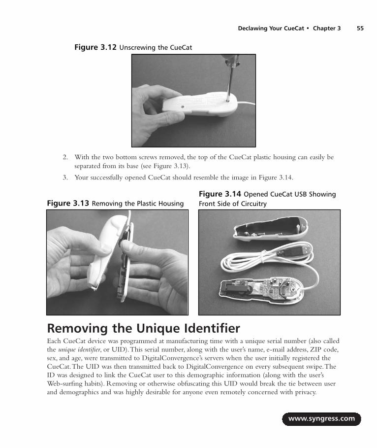
2. With the two bottom screws removed, the top of the CueCat plastic housing can easily beseparated from its base (see Figure 3.13).
3. Your successfully opened CueCat should resemble the image in Figure 3.14.
Removing the Unique IdentifierEach CueCat device was programmed at manufacturing time with a unique serial number (also calledthe unique identifier, or UID).This serial number, along with the user’s name, e-mail address, ZIP code,sex, and age, were transmitted to DigitalConvergence’s servers when the user initially registered theCueCat.The UID was then transmitted back to DigitalConvergence on every subsequent swipe.TheID was designed to link the CueCat user to this demographic information (along with the user’sWeb-surfing habits). Removing or otherwise obfuscating this UID would break the tie between userand demographics and was highly desirable for anyone even remotely concerned with privacy.
www.syngress.com
Declawing Your CueCat • Chapter 3 55
Figure 3.12 Unscrewing the CueCat
Figure 3.13 Removing the Plastic HousingFigure 3.14 Opened CueCat USB ShowingFront Side of Circuitry
287_HRD_HACK_03.qxd 1/12/04 5:27 PM Page 55

The goal of this hack is to remove the UID and replace it with a meaningless string of charactersthat does not tie the user to the CueCat device.The UID is stored in an industry-standard, non-volatile Serial EEPROM device.
Preparing for the HackNo special tools are required for this hack.All you need is a hobby knife (such as an X-ACTO knife)that you will use to cut a single trace on the CueCat circuit board to prevent the UID from beingtransmitted by the Serial EEPROM. Optionally, you could use a soldering iron to physically removethe Serial EEPROM from the CueCat circuit board. Both options work equally well.
Removing the UID: Four-Screw PS/2 CueCat Figure 3.15 shows the Serial EEPROM (denoted with an arrow) that we will be modifying. It islocated on the back of the CueCat four-screw PS/2 circuit board.
NEED TO KNOW… FIVE-PIN OR EIGHT-PIN?Depending on the variations in your particular CueCat model, the Serial EEPROM we need tomodify or remove will be either an eight-pin SOIC package or a smaller five-pin SOT23package. DigitalConvergence’s choice to use the larger or smaller package type could havebeen based on a number of factors (price or availability of the part, most likely), but they arefunctionally equivalent. The examples in this section show the more common eight-pin SOICdevice. If the five-pin SOT23 is used, it will be in the same physical location as the largerdevice and the hack can proceed as described. There is an additional set of pads underneaththe eight-pin SOIC pads for the smaller device, as shown in Figure 3.18.
Our target trace to cut is connected to pin 4 of the Serial EEPROM. First, identify pin 4 on thedevice, which is the lower-left pin if your CueCat is oriented as shown in Figure 3.16. Using the X-
www.syngress.com
56 Chapter 3 • Declawing Your CueCat
Figure 3.15 Back of CueCat Four-Screw PS/2 Showing Serial EEPROM
287_HRD_HACK_03.qxd 1/12/04 5:28 PM Page 56
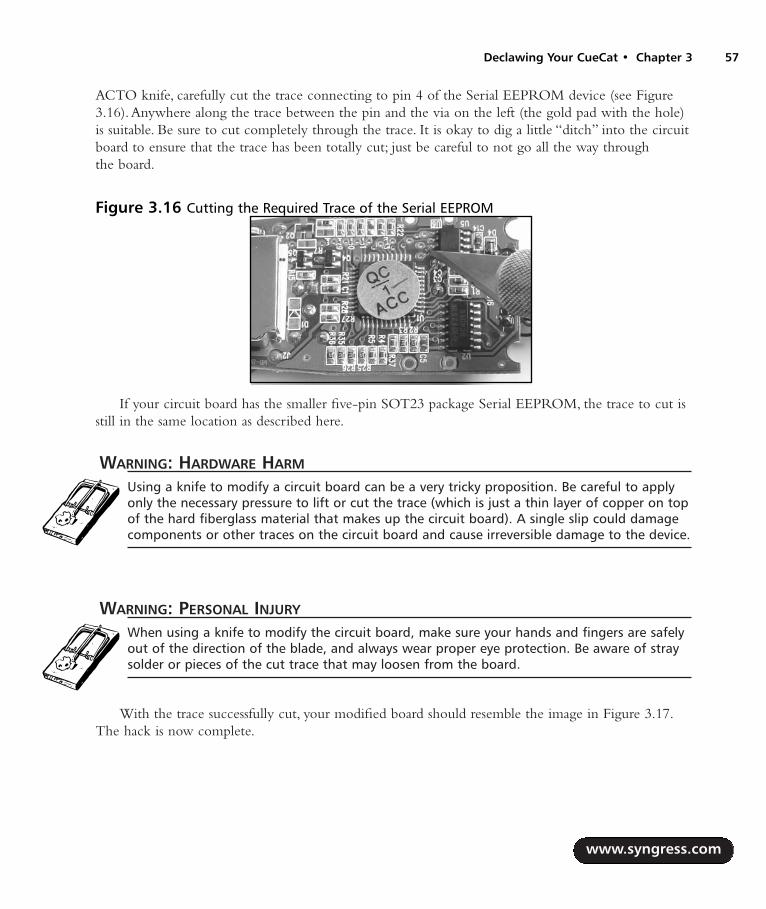
ACTO knife, carefully cut the trace connecting to pin 4 of the Serial EEPROM device (see Figure3.16).Anywhere along the trace between the pin and the via on the left (the gold pad with the hole)is suitable. Be sure to cut completely through the trace. It is okay to dig a little “ditch” into the circuitboard to ensure that the trace has been totally cut; just be careful to not go all the way through the board.
If your circuit board has the smaller five-pin SOT23 package Serial EEPROM, the trace to cut isstill in the same location as described here.
WARNING: HARDWARE HARM
Using a knife to modify a circuit board can be a very tricky proposition. Be careful to applyonly the necessary pressure to lift or cut the trace (which is just a thin layer of copper on topof the hard fiberglass material that makes up the circuit board). A single slip could damagecomponents or other traces on the circuit board and cause irreversible damage to the device.
WARNING: PERSONAL INJURY
When using a knife to modify the circuit board, make sure your hands and fingers are safelyout of the direction of the blade, and always wear proper eye protection. Be aware of straysolder or pieces of the cut trace that may loosen from the board.
With the trace successfully cut, your modified board should resemble the image in Figure 3.17.The hack is now complete.
www.syngress.com
Declawing Your CueCat • Chapter 3 57
Figure 3.16 Cutting the Required Trace of the Serial EEPROM
287_HRD_HACK_03.qxd 1/12/04 5:28 PM Page 57

An optional step is available to further ensure that the unique serial number cannot be trans-mitted by your CueCat device: Completely remove the Serial EEPROM from the circuit board witha soldering iron or very fine-tip clippers. If you choose to complete this step, your circuit boardshould now resemble the image in Figure 3.18.
WARNING: HARDWARE HARM
When removing this part, be careful not to scratch or damage any of the surrounding com-ponents or pull up any PCB traces. The easiest way to remove a surface-mount part is withan SMD rework station or using a flat-blade solder tip.
Removing the UID: Two-Screw PS/2 CueCat Figure 3.19 shows the Serial EEPROM (denoted with an arrow) that we will be modifying. It islocated on the front of the CueCat two-screw PS/2 circuit board.
www.syngress.com
58 Chapter 3 • Declawing Your CueCat
Figure 3.18 Optional Step: Circuit Board with Serial EEPROM Device Removed (Note theAdditional SOT23 Footprint Within the Serial EEPROM Area)
Figure 3.17 Hack Complete: Successfully Cut Trace of the Serial EEPROM
287_HRD_HACK_03.qxd 1/12/04 5:28 PM Page 58

Our target trace to cut is connected to pin 1 of the Serial EEPROM. First, identify pin 1 on thedevice, which is the upper-left pin if your CueCat is oriented as shown in Figure 3.20. Using the X-ACTO knife, carefully cut the trace connecting to pin 1 of the Serial EEPROM device (see Figure3.20).Anywhere along the trace between the pin and the via on the left (the gold pad with the hole)is suitable. Be sure to cut completely through the trace. It is okay to dig a little “ditch” into the circuitboard to ensure that the trace has been totally cut; just be careful to not go all the way through theboard.
WARNING: HARDWARE HARM
Using a knife to modify a circuit board can be a very tricky proposition. Be careful to applyonly the necessary pressure to lift or cut the trace (which is just a thin layer of copper on topof the hard fiberglass material that makes up the circuit board). A single slip could damagecomponents or other traces on the circuit board and cause irreversible damage to the device.
WARNING: PERSONAL INJURY
When using a knife to modify the circuit board, make sure your hands and fingers are safelyout of the direction of the blade, and always wear proper eye protection. Be aware of straysolder mask or pieces of the cut trace that may loosen from the board.
www.syngress.com
Declawing Your CueCat • Chapter 3 59
Figure 3.19 Front of CueCat Two-Screw PS/2 Showing Serial EEPROM
287_HRD_HACK_03.qxd 1/12/04 5:28 PM Page 59
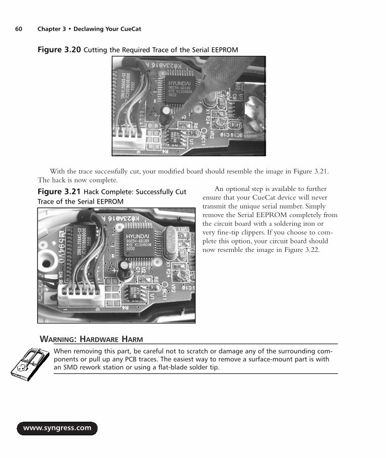
With the trace successfully cut, your modified board should resemble the image in Figure 3.21.The hack is now complete.
An optional step is available to furtherensure that your CueCat device will nevertransmit the unique serial number. Simplyremove the Serial EEPROM completely fromthe circuit board with a soldering iron orvery fine-tip clippers. If you choose to com-plete this option, your circuit board shouldnow resemble the image in Figure 3.22.
WARNING: HARDWARE HARM
When removing this part, be careful not to scratch or damage any of the surrounding com-ponents or pull up any PCB traces. The easiest way to remove a surface-mount part is withan SMD rework station or using a flat-blade solder tip.
www.syngress.com
60 Chapter 3 • Declawing Your CueCat
Figure 3.21 Hack Complete: Successfully CutTrace of the Serial EEPROM
Figure 3.20 Cutting the Required Trace of the Serial EEPROM
287_HRD_HACK_03.qxd 1/12/04 5:28 PM Page 60
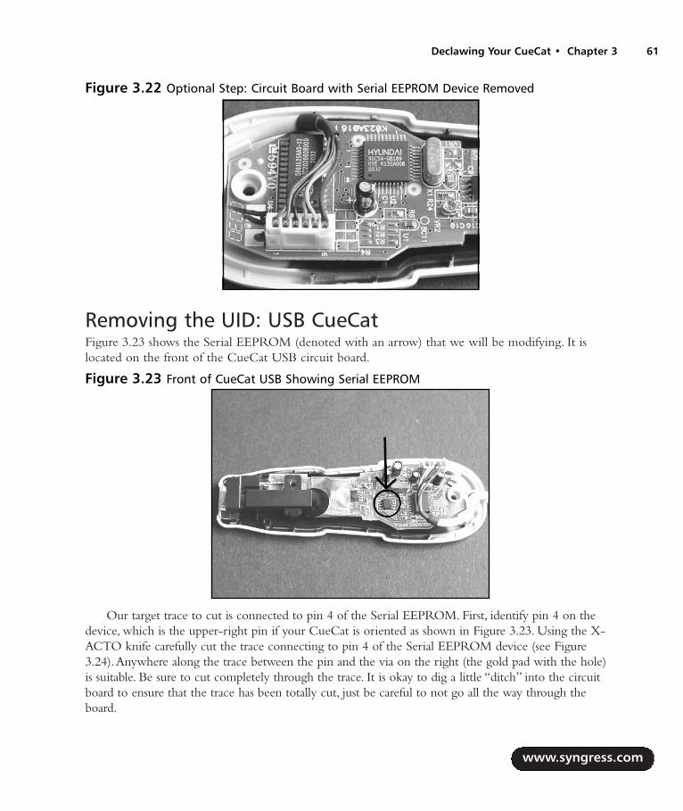
Removing the UID: USB CueCat Figure 3.23 shows the Serial EEPROM (denoted with an arrow) that we will be modifying. It islocated on the front of the CueCat USB circuit board.
Our target trace to cut is connected to pin 4 of the Serial EEPROM. First, identify pin 4 on thedevice, which is the upper-right pin if your CueCat is oriented as shown in Figure 3.23. Using the X-ACTO knife carefully cut the trace connecting to pin 4 of the Serial EEPROM device (see Figure3.24).Anywhere along the trace between the pin and the via on the right (the gold pad with the hole)is suitable. Be sure to cut completely through the trace. It is okay to dig a little “ditch” into the circuitboard to ensure that the trace has been totally cut, just be careful to not go all the way through theboard.
www.syngress.com
Declawing Your CueCat • Chapter 3 61
Figure 3.22 Optional Step: Circuit Board with Serial EEPROM Device Removed
Figure 3.23 Front of CueCat USB Showing Serial EEPROM
287_HRD_HACK_03.qxd 1/12/04 5:28 PM Page 61

WARNING: HARDWARE HARM
Using a knife to modify a circuit board can be a very tricky proposition. Be careful to applyonly the necessary pressure to lift or cut the trace (which is just a thin layer of copper on topof the hard fiberglass material that makes up the circuit board). A single slip could damagecomponents or other traces on the circuit board and cause irreversible damage to the device.
WARNING: PERSONAL INJURY
When using a knife to modify the circuit board, make sure your hands and fingers are safelyout of the direction of the blade, and always wear proper eye protection. Be aware of straysolder or pieces of the cut trace that may loosen from the board.
With the trace successfully cut, your modified board should resemble the image in Figure 3.25.The hack is now complete.
www.syngress.com
62 Chapter 3 • Declawing Your CueCat
Figure 3.24 Cutting the Required Trace of the Serial EEPROM
287_HRD_HACK_03.qxd 1/12/04 5:28 PM Page 62

An optional step is available to further ensure that your CueCat device will never transmit theunique serial number. Simply remove the Serial EEPROM completely from the circuit board with a sol-dering iron or very fine-tip clippers.Your circuit board should now resemble the image in Figure 3.26.
WARNING: HARDWARE HARM
Be careful when removing the part to not scratch or damage any of the surrounding compo-nents or pull up any PCB traces. The easiest way to remove a surface-mount part is with anSMD rework station or using a flat-blade solder tip.
www.syngress.com
Declawing Your CueCat • Chapter 3 63
Figure 3.25 Hack Complete: Successfully Cut Trace of the Serial EEPROM (Close Up)
Figure 3.26 Optional Step: Circuit Board with Serial EEPROM Device Removed
287_HRD_HACK_03.qxd 1/12/04 5:28 PM Page 63

Under the Hood: How the Hack WorksBefore the hack, a typical unmodified CueCat response after scanning a sample Code 39 barcode(9105527106) looks as follows:
.C3nZC3nZC3n2ChPZEND1DxnY.ahb6.ENjZDNzXDhjZDq.
Each string returned by the CueCat contains three sections, all encoded with a proprietaryencoding scheme devised by DigitalConvergence.The information includes a unique serial number,barcode type, and barcode data. For more information on the proprietary encoding scheme, see the“Technical Information” section toward the end of this chapter.The “Removing the ProprietaryBarcode Encoding” hack in this chapter completely removes this obfuscation.
After we modify the CueCat to remove the unique identifier, the string corresponding to theidentifier is now a nondescript pattern. Using the same Code 39 sample we examined previously, themodified four-screw PS/2 version returns the following string:
.BM5UBM5UBM5UBM5UBM5UBM5U.ahb6.ENjZDNzXDhjZDq.
The modified two-screw PS/2 and USB versions return another nondescript pattern with norelation to the original encoded serial number:
.VlY8VlY8VlY8VlY8VlY8VlY8.ahb6.ENjZDNzXDhjZDq.
Depending on the electrical characteristics of your version of CueCat, the pattern replacing thefirst part of the encoding barcode might vary from our examples. If CueCat no longer transmits theserial number portion, you can consider the hack complete.
The UID for each CueCat is stored in an industry-standard, nonvolatile Serial EEPROM device.Removing the Serial EEPROM device from the circuit board or cutting a particular trace coming fromthe Serial EEPROM will prevent data from being transmitted back to the CueCat microprocessor.
Serial EEPROMs are extremely common in the engineering industry and require minimal cir-cuitry to read and write to.They are also notoriously insecure and as such often do not provide anytype of security features.Thus, it is possible to attach a device programmer to the device, even while itis still attached to the circuit board, and read and write at will.
The primary Serial EEPROM used in the CueCat devices is an Antek Semiconductor 93LC46or functional equivalent.The 93LC46 provides 1024 bits (128 bytes) of nonvolatile data storage.Thisis a small amount of memory, though it’s well within reason to store the simple 18-byte serialnumber.The 93xx family of Serial EEPROMs use a three-wire interface to transfer data to and fromthe host:
Serial Data Input (DI)
Serial Data Output (DO)
Serial Data Clock (SK or CLK)
An ORG pin is used to select the internal memory organization of the device. If the ORG pin ispulled HIGH, the memory is organized as 64 pages of 2 bytes (16 bits) each. If the ORG pin is
www.syngress.com
64 Chapter 3 • Declawing Your CueCat
287_HRD_HACK_03.qxd 1/12/04 5:28 PM Page 64

pulled LOW, the internal memory of the EEPROM is organized as 128 pages of 1 byte (8 bits) each.For the four-screw PS/2 CueCat, the ORG pin is pulled HIGH. For the later two-screw PS/2 andUSB CueCats, the ORG pin is pulled LOW. In either configuration, a total of 128 bytes of storagememory is available.
A clever design feature of the four-screw PS/2 CueCat is its support for a smaller five-pinSOT23 Serial EEPROM along with the larger eight-pin SOIC device.You can see the additional setof SOT23 pads within the larger SOIC footprint in Figure 3.18.The SOT23 version of the SerialEEPROM is a 24C01A part with rotated package pinout.
The 24xx family of Serial EEPROMs uses a two-wire I2C bus protocol to transfer data to andfrom the host:
Serial Data (SDA)
Serial Clock Input (SCL)
The SDA pin is bidirectional, providing both transmit and receive functionality.The SCL pin isused to clock data into the EEPROM device on a positive clock edge and out of the device on anegative clock edge.The memory in the 24C01A is internally organized as 16 pages of 8 bytes each,also corresponding to a total of 128 bytes (the same amount of memory as in the 93LC46).
Functionally, the two devices (the 24xx and the 93xx) will act the same, but technically they aredifferent devices with different operating characteristics.This is why replacing an SOT23 device withan SOIC device on the CueCat, or vice versa, would not work.The firmware running on theCueCat needs to support the particular family of Serial EEPROM that is installed (e.g., the 93xx or24xx, but not both).
Figure 3.27 shows the pinouts for both the 93LC46 and 24C01A Serial EEPROMs. In eithercase, the SDA line of the 24C01A and the DO line of the 93LC46 connect to pin 4 of the largerSOIC footprint on the circuit board, so regardless of which device is used, cutting the trace from pin4 will prevent the unique serial number from being transmitted by the Serial EEPROM.
On the CueCat two-screw PS/2 version, the actual connection coming from pin 4 goes directlyunderneath the Serial EEPROM, making it impossible to cut unless the Serial EEPROM is com-pletely removed (in which case, the hack would be complete). Instead, pin 1 of the Serial EEPROMis cut and achieves the same goal. Pin 1 corresponds to the Chip Select (CS) line, which enables ordisables the Serial EEPROM depending on if that pin is LOW or HIGH. Since the microprocessorno longer has access to the CS line now that it has been cut, the Serial EEPROM cannot be enabledand will not transmit or receive data.
www.syngress.com
Declawing Your CueCat • Chapter 3 65
287_HRD_HACK_03.qxd 1/12/04 5:28 PM Page 65
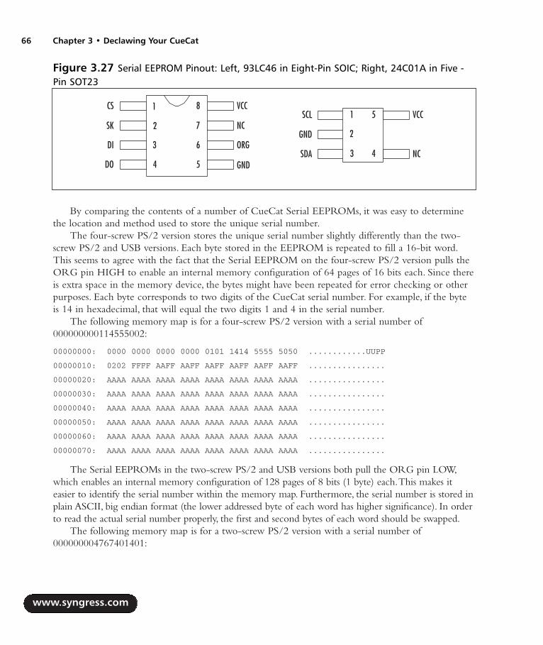
By comparing the contents of a number of CueCat Serial EEPROMs, it was easy to determinethe location and method used to store the unique serial number.
The four-screw PS/2 version stores the unique serial number slightly differently than the two-screw PS/2 and USB versions. Each byte stored in the EEPROM is repeated to fill a 16-bit word.This seems to agree with the fact that the Serial EEPROM on the four-screw PS/2 version pulls theORG pin HIGH to enable an internal memory configuration of 64 pages of 16 bits each. Since thereis extra space in the memory device, the bytes might have been repeated for error checking or otherpurposes. Each byte corresponds to two digits of the CueCat serial number. For example, if the byteis 14 in hexadecimal, that will equal the two digits 1 and 4 in the serial number.
The following memory map is for a four-screw PS/2 version with a serial number of000000000114555002:
00000000: 0000 0000 0000 0000 0101 1414 5555 5050 ............UUPP
00000010: 0202 FFFF AAFF AAFF AAFF AAFF AAFF AAFF ................
00000020: AAAA AAAA AAAA AAAA AAAA AAAA AAAA AAAA ................
00000030: AAAA AAAA AAAA AAAA AAAA AAAA AAAA AAAA ................
00000040: AAAA AAAA AAAA AAAA AAAA AAAA AAAA AAAA ................
00000050: AAAA AAAA AAAA AAAA AAAA AAAA AAAA AAAA ................
00000060: AAAA AAAA AAAA AAAA AAAA AAAA AAAA AAAA ................
00000070: AAAA AAAA AAAA AAAA AAAA AAAA AAAA AAAA ................
The Serial EEPROMs in the two-screw PS/2 and USB versions both pull the ORG pin LOW,which enables an internal memory configuration of 128 pages of 8 bits (1 byte) each.This makes iteasier to identify the serial number within the memory map. Furthermore, the serial number is stored inplain ASCII, big endian format (the lower addressed byte of each word has higher significance). In orderto read the actual serial number properly, the first and second bytes of each word should be swapped.
The following memory map is for a two-screw PS/2 version with a serial number of000000004767401401:
www.syngress.com
66 Chapter 3 • Declawing Your CueCat
Figure 3.27 Serial EEPROM Pinout: Left, 93LC46 in Eight-Pin SOIC; Right, 24C01A in Five -Pin SOT23
DO
CS
SK
DI
1
GND
VCC
NC
ORG
2
3
4
8
7
6
5SDA
SCL
GND
NC
VCC1
2
3
5
4
287_HRD_HACK_03.qxd 1/12/04 5:28 PM Page 66

00000000: FFFF 3030 3030 3030 3030 3734 3736 3034 ..00000000747604
00000010: 3431 3130 FFFF FFFF FFFF FFFF FFFF FFFF 4110............
00000020: FFFF FFFF FFFF FFFF FFFF FFFF FFFF FFFF ................
00000030: FFFF FFFF FFFF FFFF FFFF FFFF FFFF FFFF ................
00000040: FFFF FFFF FFFF FFFF FFFF FFFF FFFF FFFF ................
00000050: FFFF FFFF FFFF FFFF FFFF FFFF FFFF FFFF ................
00000060: FFFF FFFF FFFF FFFF FFFF FFFF FFFF FFFF ................
00000070: FFFF FFFF FFFF FFFF FFFF FFFF FFFF FFFF ................
The next memory map is for a USB version with a serial number of 000000005390946601:
00000000: FFFF 3030 3030 3030 3030 3335 3039 3439 ..00000000350949
00000010: 3636 3130 FFFF FFFF FFFF FFFF FFFF FFFF 6610............
00000020: FFFF FFFF FFFF FFFF FFFF FFFF FFFF FFFF ................
00000030: FFFF FFFF FFFF FFFF FFFF FFFF FFFF FFFF ................
00000040: FFFF FFFF FFFF FFFF FFFF FFFF FFFF FFFF ................
00000050: FFFF FFFF FFFF FFFF FFFF FFFF FFFF FFFF ................
00000060: FFFF FFFF FFFF FFFF FFFF FFFF FFFF FFFF ................
00000070: FFFF FFFF FFFF FFFF FFFF FFFF FFFF FFFF ................
Removing the Proprietary Barcode EncodingPerforming this hack will allow you to read standard barcodes with the CueCat and obtain plainASCII output as opposed to the proprietary CueCat format (which was nothing more than a weakobfuscation scheme; see the “Technical Information” section at the end of this chapter for more infor-mation).The output is sent to your computer via the PS/2 or USB interface treated as typed text(normal decoded keyboard characters). Once the device is plugged into your PC, the barcode textwill be output wherever the cursor is positioned.The text output could then be passed into anynumber of data cataloging programs, spreadsheets, or other user-specific application.
This modification is especially useful now that DigitalConvergence is essentially defunct and theCueCat is just another commodity gadget. Creating a computer-interfaced barcode scanner in only afew minutes of hacking is time well spent.
Preparing for the HackThe hack to convert the proprietary barcode encoding into a plaintext output is very simple.Youneed the following tools for this hack:
An X-ACTO hobby knife
A flat-head screwdriver, jeweler’s size
A soldering iron for the four-screw PS/2 model
www.syngress.com
Declawing Your CueCat • Chapter 3 67
287_HRD_HACK_03.qxd 1/12/04 5:28 PM Page 67

A 4- to 5-inch piece of jumper wire For the four-screw PS/2 model, solid or twisted braid,22AWG or thinner
For the two-screw PS/2 and USB versions, the hack consists simply of lifting the proper pin ofone of the chips (the microprocessor) on the circuit board.This can usually be done by just heatingthe desired pin with the soldering iron while gently prying the pin off the pad with the X-ACTOknife or the flat-tip screwdriver.The four-screw PS/2 version requires a jumper wire to be added tothe circuit board instead.
Removing the Encoding from the Four-Screw PS/2 CueCat Hacking this early version of the CueCat is slightly more complicated than the subsequent versionsreleased by DigitalConvergence, because it requires you to solder a jumper wire between two pointson the circuit board.
On the front of the device, located on the left side, a large square pad is denoted with a white +sign and has a red wire already connected to it (Connection 1 in Figure 3.28). First, solder one side ofthe jumper wire to this point. Make sure that the red wire remains soldered to the pad when you aredone with your addition.
On the bottom-right section of the circuit board is a row of solder pads (also called testpoints).Depending on the revision number of your CueCat (which can be found silk-screened in white ontop of the circuit board, as shown in Figure 3.31), the other end of the jumper wire will connect toone of these testpoints.The desired test point is always the pad that is connected to resistor R29(identified in Figure 3.29).
www.syngress.com
68 Chapter 3 • Declawing Your CueCat
Figure 3.28 Front of Four-Screw PS/2 Showing Connection Points
287_HRD_HACK_03.qxd 1/12/04 5:28 PM Page 68

The test point makes an easy location to which to solder the jumper wire.Table 3.1 shows thelocation of the testpoint for the different known PCB revision numbers. If your revision is not listedin Table 3.1, simply visually trace the connection from R29 to the testpoint or use a multimeter tocheck continuity between the two points.
Table 3.1 Testpoint Location for Various CueCat Four-Screw PS/2 Revisions
Testpoint Location (Pad # from Left When Device Is CueCat Board Revision Oriented as in Figure 3.31)
FM+H Rev. 0.3 2TO+E Rev. 2.1 2TM+H Rev. 0.3 2HO+E Rev. 0.3 4HW+H Rev. 2.1 4HM+H Rev. 1.1 4
In this example, our CueCat is revision TO+E Rev. 2.1, so the jumper wire will be connected tothe second pad from the left (Connection 2 in Figure 3.28).
Once the jumper has been added, your modified CueCat should resemble the image in Figure3.30. Figure 3.31 shows a close-up of the row of test points.
www.syngress.com
Declawing Your CueCat • Chapter 3 69
Figure 3.29 Back of Four-Screw PS/2 Showing R29 and Testpoint
287_HRD_HACK_03.qxd 1/12/04 5:28 PM Page 69
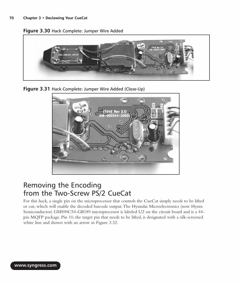
Removing the Encoding from the Two-Screw PS/2 CueCatFor this hack, a single pin on the microprocessor that controls the CueCat simply needs to be liftedor cut, which will enable the decoded barcode output.The Hyundai Microelectronics (now HynixSemiconductor) GMS90C54-GB189 microprocessor is labeled U2 on the circuit board and is a 44-pin MQFP package. Pin 10, the target pin that needs to be lifted, is designated with a silk-screenedwhite line and shown with an arrow in Figure 3.32.
www.syngress.com
70 Chapter 3 • Declawing Your CueCat
Figure 3.30 Hack Complete: Jumper Wire Added
Figure 3.31 Hack Complete: Jumper Wire Added (Close-Up)
287_HRD_HACK_03.qxd 1/12/04 5:28 PM Page 70

Some versions of the CueCat two-screw PS/2 version may use a SyncMos SM2958 micropro-cessor in place of the more common GMS90C54.The SyncMos part is a direct clone of theGMS90C54, and the described hack functions exactly the same.
Simply use a soldering iron to heat the pin and lift it up with a small jeweler’s screwdriver or theedge of an X-ACTO knife (see Figure 3.33). If desired, the pin could be clipped off and completelyremoved.
WARNING: HARDWARE HARM
While lifting the desired pin off the circuit board, be careful not to heat up the device toomuch or cause any surrounding pins to be lifted up, bent, or shorted together with solder.The pins are very close together, and you might want to use a magnifying glass to inspectyour work.
Once pin 10 has been lifted, the hack is complete.Your modified CueCat should resemble theimage in Figure 3.34.
www.syngress.com
Declawing Your CueCat • Chapter 3 71
Figure 3.33 Heating and Liftingthe Pin of the Microprocessor
Figure 3.34 Hack Complete: Pin 10of Microprocessor Lifted (Close-Up)
Figure 3.32 Front of CueCat Two-Screw PS/2 Showing Microprocessor Pin
287_HRD_HACK_03.qxd 1/12/04 5:28 PM Page 71
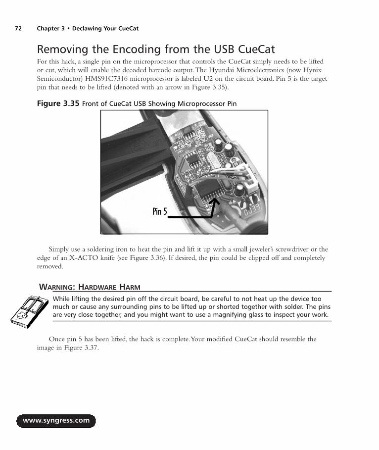
Removing the Encoding from the USB CueCatFor this hack, a single pin on the microprocessor that controls the CueCat simply needs to be liftedor cut, which will enable the decoded barcode output.The Hyundai Microelectronics (now HynixSemiconductor) HMS91C7316 microprocessor is labeled U2 on the circuit board. Pin 5 is the targetpin that needs to be lifted (denoted with an arrow in Figure 3.35).
Simply use a soldering iron to heat the pin and lift it up with a small jeweler’s screwdriver or theedge of an X-ACTO knife (see Figure 3.36). If desired, the pin could be clipped off and completelyremoved.
WARNING: HARDWARE HARM
While lifting the desired pin off the circuit board, be careful to not heat up the device toomuch or cause any surrounding pins to be lifted up or shorted together with solder. The pinsare very close together, and you might want to use a magnifying glass to inspect your work.
Once pin 5 has been lifted, the hack is complete.Your modified CueCat should resemble theimage in Figure 3.37.
www.syngress.com
72 Chapter 3 • Declawing Your CueCat
Figure 3.35 Front of CueCat USB Showing Microprocessor Pin
287_HRD_HACK_03.qxd 1/12/04 5:28 PM Page 72

Under the Hood: How the Hack WorksOnce the CueCat has been successfully “neutered” to read all standard barcodes, the raw ASCII dataof the barcode will be transmitted via the PS/2 or USB port to the PC and displayed as regular key-board input.The barcode type is no longer transmitted.Table 3.2 shows the various barcode types thatcan be read and are supported by the CueCat (listing provided by http://mailcom.com/BarcodeTest).
Before the hack, a typical unmodified CueCat response after scanning a sample Code 39 barcode(9105527106) looks as follows:
.C3nZC3nZC3n2ChPZEND1DxnY.ahb6.ENjZDNzXDhjZDq.
Or, if the CueCat has been modified to remove the unique serial number as described in the“Removing the Unique Identifier” section of this chapter, the sample Code 39 barcode would appearas something like this:
.BM5UBM5UBM5UBM5UBM5UBM5U.ahb6.ENjZDNzXDhjZDq.
After modifying the CueCat to remove the proprietary encoding, the same Code 39 sample willdisplay simply as a string of raw ASCII barcode data:
9105527106
Table 3.2 Barcode Types Supported by CueCat
Barcode Category CueCat Identifier Barcode Type
Alphanumeric 128 Code 128E28 UCC/EAN 128 (Code 128 starting with
the FUNC1 character)
www.syngress.com
Declawing Your CueCat • Chapter 3 73
Figure 3.37 Hack Complete: Pin 5 ofMicroprocessor Lifted (Close-Up)
Figure 3.36 Heating and Lifting the Pin ofthe Microprocessor
Continued
287_HRD_HACK_03.qxd 1/12/04 5:28 PM Page 73
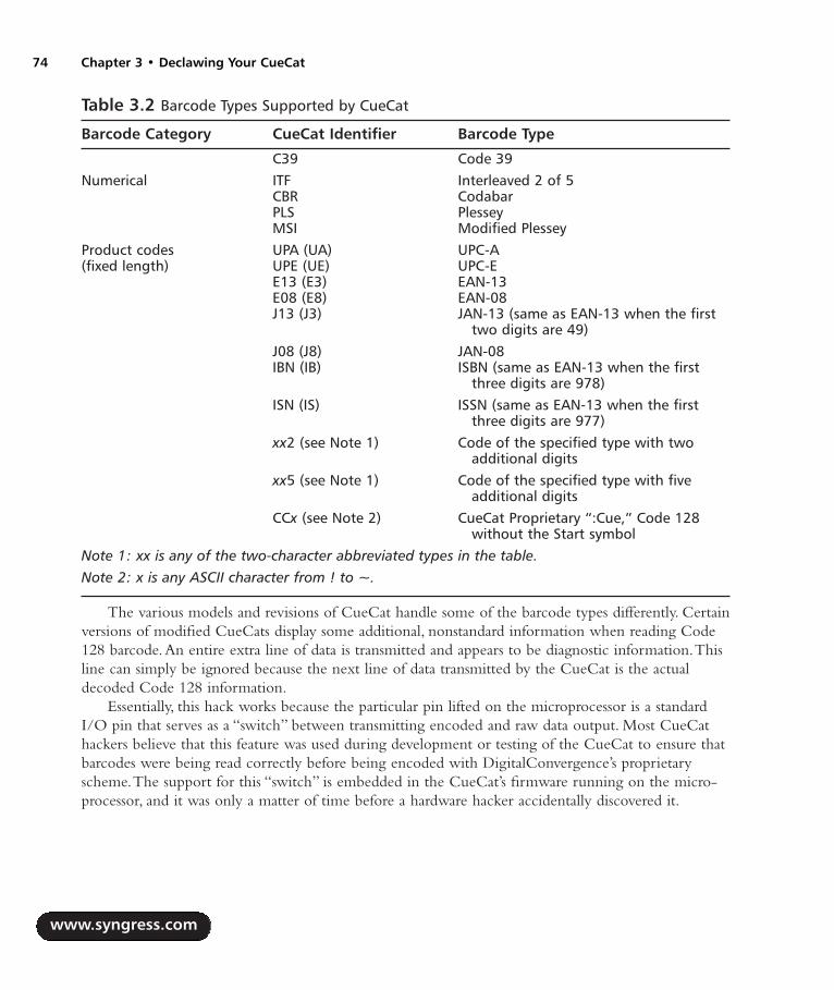
Table 3.2 Barcode Types Supported by CueCat
Barcode Category CueCat Identifier Barcode Type
C39 Code 39Numerical ITF Interleaved 2 of 5
CBR CodabarPLS PlesseyMSI Modified Plessey
Product codes UPA (UA) UPC-A(fixed length) UPE (UE) UPC-E
E13 (E3) EAN-13E08 (E8) EAN-08J13 (J3) JAN-13 (same as EAN-13 when the first
two digits are 49)J08 (J8) JAN-08IBN (IB) ISBN (same as EAN-13 when the first
three digits are 978)ISN (IS) ISSN (same as EAN-13 when the first
three digits are 977)xx2 (see Note 1) Code of the specified type with two
additional digitsxx5 (see Note 1) Code of the specified type with five
additional digitsCCx (see Note 2) CueCat Proprietary “:Cue,” Code 128
without the Start symbolNote 1: xx is any of the two-character abbreviated types in the table. Note 2: x is any ASCII character from ! to ~.
The various models and revisions of CueCat handle some of the barcode types differently. Certainversions of modified CueCats display some additional, nonstandard information when reading Code128 barcode.An entire extra line of data is transmitted and appears to be diagnostic information.Thisline can simply be ignored because the next line of data transmitted by the CueCat is the actualdecoded Code 128 information.
Essentially, this hack works because the particular pin lifted on the microprocessor is a standardI/O pin that serves as a “switch” between transmitting encoded and raw data output. Most CueCathackers believe that this feature was used during development or testing of the CueCat to ensure thatbarcodes were being read correctly before being encoded with DigitalConvergence’s proprietaryscheme.The support for this “switch” is embedded in the CueCat’s firmware running on the micro-processor, and it was only a matter of time before a hardware hacker accidentally discovered it.
www.syngress.com
74 Chapter 3 • Declawing Your CueCat
287_HRD_HACK_03.qxd 1/12/04 5:28 PM Page 74

Technical InformationAlthough the hardware designs of the CueCat revisions varied slightly, the functional operation of theunit was the same. Figure 3.38 is a system block diagram for the CueCat’s major functions. (The con-cept illustrated here is from EDN,“Not Every Cat Lands on Its Feet,” September 4, 2003.)
At a high level, the operation of the CueCat is as follows:
1. LEDs from inside the CueCat are enabled to illuminate the scanning surface.
2. As the CueCat is moved over the barcode on the printed page, the reflections from theblack and white “bars” of the barcode are detected by the photosensor, resulting in a varyingcurrent.The photosensor is protected by a metal shield to reduce AC-induced noise into thecircuit.
3. The output from the photosensor is passed through a high-gain amplifier and filter to cleanup the signal.
4. The microprocessor then samples the signal at a high clock rate and processes the informa-tion into actual barcode data.
5. The unique serial number of each device is read from the Serial EEPROM.
6. The unit then encodes the unique serial number and barcode data into a proprietary format(see the “CueCat Encoding Scheme” section that follows for more information), which isnow ready to be transmitted to the host PC.
For the PS/2 version, an analog switch serves as a multiplexer to effectively seize control of thePS/2 bus and disable any actual keyboard input to the PC while the CueCat is sending its data.TheUSB model operates in essentially the same manner, except the analog switch in the final stage isreplaced with a USB interface.
www.syngress.com
Declawing Your CueCat • Chapter 3 75
Figure 3.38 CueCat System Block Diagram, PS/2 Model
I/V
SerialEEPROM SRAM
Microcontroller
Clock
AnalogSwitch
Power
ClockData
PS/2 Keyboard Port
Photo Sensor
287_HRD_HACK_03.qxd 1/12/04 5:28 PM Page 75

The CueCat Encoding SchemeThe proprietary encoding scheme CueCat uses is nothing more than base-64 encoding with an addi-tional XOR against a constant (the ASCII character C) to first obfuscate the data. Base-64 (formallydefined as part of RFC 1521, www.faqs.org/rfcs/rfc1521.html) is used to simply convert a generalbyte array (such as raw binary data) into a printable byte array of ASCII characters.
After Stephen Satchell performed detailed cryptanalysis of the CueCat encoding scheme inSeptember 2000, it was hypothesized that the encoding scheme was not used to hide or protect thetransmitted data (as many people thought) but that it simplified the process of placing the data into aURL with a minimum of post-processing on the server side.The added step of the XOR operationcould not be determined, however, and might have been a thinly veiled attempt byDigitalConvergence to make its data appear more proprietary than it actually was.
The encoded string transmitted by the CueCat consists of three parts, with a period (.) serving asa delimiter:
Unique serial number
Barcode type
Barcode data
A typical unmodified CueCat response after scanning a sample Code 39 barcode (9105527106)looks as follows:
.C3nZC3nZC3n2ChPZEND1DxnY.ahb6.ENjZDNzXDhjZDq.
So, in this example, the three encoded parts are:
Unique serial number = C3nZC3nZC3n2ChPZEND1DxnY
Barcode type = ahb6
Barcode data = ENjZDNzXDhjZDq
The base-64 encoding table used is an alternate of the regular scheme, placing the lowercasealphabet before the uppercase:
abcdefghijklmnop
qrstuvwxyzABCDEF
GHIJKLMNOPQRSTUV
WXYZ0123456789+/
After running our three encoded parts through a base-64 decoder, we are left with intermediateresults of ssssssssvpzszwuusr for the serial number, pz for the barcode type, and zrsvvqtrsu for the bar-code data. Passing the components through an XOR against the ASCII character C (43 in hexadec-imal) gives us the final decoded information:
Unique serial number = 000000005390946601
www.syngress.com
76 Chapter 3 • Declawing Your CueCat
287_HRD_HACK_03.qxd 1/12/04 5:28 PM Page 76

Barcode type = C39
Barcode data = 9105527106
After the CueCat scheme was discovered, open-source software and drivers began popping up forevery language, operating system, and interface imaginable, including but not limited to C, C++,PHP, Java, JavaScript, Python, Perl, PAM, Microsoft Windows, Macintosh, Linux, and other UNIXvariants.These tools would decode the proprietary CueCat encoding scheme and display the decodedinformation without using the software provided by DigitalConvergence. See the “Open-SourceCueCat Software and Drivers” in the “CueCat Litter Box: Web Links and Other Resources” sectionfor links.The most compact and efficient decoder is a Perl script by Larry Wall, Perl creator and guru,shown here:
#!/usr/bin/perl -n
printf "Serial: %s Type: %s Code: %s\n",
map
tr/a-zA-Z0-9+-/ -_/;
$_ = unpack 'u', chr(32 + length()*3/4) . $_;
s/\0+$//;
$_ ^= “"C" x length;
/\.([^.]+)/g;
More Physical Model Variations As mentioned throughout this chapter, there are three major designs of the CueCat, each with its ownset of revisions.Although there are too many distinct revisions to discuss in this chapter, we have covered
the most common set.This section shows someadditional physical differences among the majorversions: the four-screw PS/2, the two-screwPS/2, and the USB. Most of the noted differ-ences are from the original four-screw PS/2design and the subsequent two-screw PS/2 andUSB designs (which appear to be very similar, ifnot exact, in physical housing design).
Figure 3.39 shows a side-view comparisonof the CueCat housings from the four-screwand two-screw PS/2 versions.The length of thefour-screw housing is slightly shorter than thetwo-screw version.The length was increasedslightly for later versions of the CueCat, possiblybecause of a change in manufacturing technolo-gies or to support additional circuitry or a newphoto sensor design.
www.syngress.com
Declawing Your CueCat • Chapter 3 77
Figure 3.39 Length Comparison of CueCatHousings: Top, Four-Screw PS/2; Bottom, Two-Screw PS/2
287_HRD_HACK_03.qxd 1/12/04 5:28 PM Page 77

Figure 3.40 shows another variance between the original four-screw PS/2 version and subsequentversions.The scanning “orifice” (or “mouth”) of the device where the LED and photosensor are posi-tioned (the primary components of a barcode scanner that “read” the barcode) is a large square shapefor the four-screw version and a narrow rectangular shape for the others.
Finally, we examine the back (or “tail”) of the CueCats.As shown in Figure 3.41, the only majorvariation is the existence of a stress-relief grommet on the four-screw device. (We previously showedan internal view of the cable and circuitry in Figure 3.6.) This appears to have been removed in alllater versions of CueCat hardware, since cable stress-relief features were built right into the plasticenclosure (as shown in Figures 3.11 and 3.14).
More History of Political and Legal IssuesBetween August and September 2000, lawyers representing DigitalConvergence began a witch huntand crackdown on all Web sites that discussed and/or detailed any modifications to the CueCat hard-ware or software.As a result, not only were the hardware hacking and experimentation with theCueCat not deterred, but dozens of mirror Web sites popped up to make sure the information up tothat date would not completely disappear.Although over time many of the mirror sites and personalWeb pages of those who experimented with the CueCat were taken down, a handful of sites stillremain with enough information for any reader to spend a weekend modifying his or her CueCat.Figure 3.42 is a sample of one of the many “notice of infringement” letters (essentially just a formletter) sent to potential violators by New York-based law firm Kenyon & Kenyon.
www.syngress.com
78 Chapter 3 • Declawing Your CueCat
Figure 3.40 Front of CueCat ShowingScanning “Orifice” Variations: Left, Four-ScrewPS/2; Center, Two-Screw PS/2; Right, USB
Figure 3.41 Back of CueCat ShowingConnector Cable Variations: Left, Four-Screw PS/2; Right, Two-Screw PS/2
287_HRD_HACK_03.qxd 1/12/04 5:28 PM Page 78
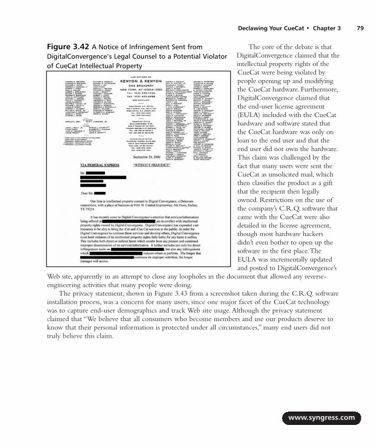
The core of the debate is thatDigitalConvergence claimed that theintellectual property rights of theCueCat were being violated bypeople opening up and modifyingthe CueCat hardware. Furthermore,DigitalConvergence claimed thatthe end-user license agreement(EULA) included with the CueCathardware and software stated thatthe CueCat hardware was only onloan to the end user and that theend user did not own the hardware.This claim was challenged by thefact that many users were sent theCueCat as unsolicited mail, whichthen classifies the product as a giftthat the recipient then legallyowned. Restrictions on the use ofthe company’s C.R.Q. software thatcame with the CueCat were alsodetailed in the license agreement,though most hardware hackersdidn’t even bother to open up thesoftware in the first place.TheEULA was incrementally updatedand posted to DigitalConvergence’s
Web site, apparently in an attempt to close any loopholes in the document that allowed any reverse-engineering activities that many people were doing.
The privacy statement, shown in Figure 3.43 from a screenshot taken during the C.R.Q. softwareinstallation process, was a concern for many users, since one major facet of the CueCat technologywas to capture end-user demographics and track Web site usage.Although the privacy statementclaimed that “We believe that all consumers who become members and use our products deserve toknow that their personal information is protected under all circumstances,” many end users did nottruly believe this claim.
www.syngress.com
Declawing Your CueCat • Chapter 3 79
Figure 3.42 A Notice of Infringement Sent fromDigitalConvergence’s Legal Counsel to a Potential Violatorof CueCat Intellectual Property
287_HRD_HACK_03.qxd 1/12/04 5:28 PM Page 79

DigitalDemographics, a sister site to DigitalConvergence, located at a non-existant www.digi-taldemographics.com, was not shy in hiding the true intentions of CueCat data gathering.At onetime, its Web site stated:“DigitalDemographics’ parallel mission is to gather demographic and psycho-graphic information from our :CRQ users, subscribers, and :CueCat device users.” It went on to listthe various data types that were collected and analyzed:
Demographic profiles
Historical cue data
Responsiveness to relevant information on the tabs
Responsiveness to relevant information on the On:CRQ Web site
Polling data
Panelist data (from volunteers who participate in special interest panels)
Specific program cue and scratch data
Survey data from opt-in respondents and volunteer panelists
Direct responsiveness to offers
Cross-media response profiles
Multiple response profiles from same segment/media
Industry-specific demographic profiling
Not surprisingly, after DigitalConvergence came under scrutiny for its disregard of personal pri-vacy, the DigitalDemographics site was taken down and redirected to the main CueCat site.
At least one known public attack on DigitalConvergence’s servers leaked personal informationabout a number of the company’s customers. On September 15, 2000, DigitalConvergence updated itsWeb site with the following news:“DigitalConvergence Corporation experienced a security breach that
www.syngress.com
80 Chapter 3 • Declawing Your CueCat
Figure 3.43 C.R.Q. Installation Software Screenshot: Privacy Statement
287_HRD_HACK_03.qxd 1/12/04 5:28 PM Page 80

may have exposed certain members’ names and email addresses.The company was alerted of breachefforts by Peter Thomas at Securitywatch.com.The company has secured the site and is conducting athorough security examination.” DigitalConvergence tried to reduce the impact of the attack byreleasing a press release on a Friday evening, hoping that the news would be forgotten over theweekend. Fortunately, media outlets picked up the story on Monday morning. It turns out that a plain-text file containing user information was left accessible on a public-facing Web server, open to all theworld.The “security breach” was nothing more than sloppiness by the administrators of theDigitalConvergence Web servers.To attempt to pacify affected users of the breach, DigitalConvergencewas offering free $10 Radio Shack gift certificates for a short period of time.
Figure 3.44 shows a rather humorous ending to this story as the C.R.Q. installation softwareattempts to “phone home” to the now-departed DigitalConvergence Web server.
CueCat Litter Box: Web Links and Other ResourcesThe following list is a selection of the most informational and complete CueCat Web sites still avail-able.At the peak of the CueCat controversy (circa 2000), hundreds of Web sites existed with hardwarehacking, reverse-engineering, and software decoding techniques. Many of those sites have since beenremoved due to threatening legal actions of the law firm representing DigitalConvergence.A Googlesearch of the term CueCat should give you enough news articles, personal rants, and technical infor-mation to last quite a while.
Dissecting the CueCat: http://air-soldier.com/~cuecat The premier Web site for allthings CueCat. Reverse engineering, technical details, political issues, and additional links.
CueCat: www.flyingbuttmonkeys.com/foocat News, information, and software for thefree software community.
www.syngress.com
Declawing Your CueCat • Chapter 3 81
Figure 3.44 C.R.Q. Installation Software Trying to Connect to the Now-DefunctDigitalConvergence Server
287_HRD_HACK_03.qxd 1/12/04 5:28 PM Page 81

How to Neuter a Cat: www.cexx.org/cuecat.htm.
Azalea Software CueCat Portmortem:www.azalea.com/QTools/CueCatPostmortem.pdf Commentary on the CueCattechnology.
CueCat Principles of Operation: www.fluent-access.com/wtpapers/cuecat/index.html A collection of essays.
“The CueCat: Balancing Function and Privacy Can Be a Challenge,” LaurenWeinstein, September 2, 2000: www.vortex.com/privacy/priv.09.19.
“Perl and :CueCat Help You Roll Your Own Data Capture,” Brent Michalski, Dr.Dobb’s Online: www.ddj.com/documents/s=1498/ddj0101pl.
Open-Source CueCat Software and Drivers http://freshmeat.net/search/?q=cuecat A collection of open-source projects.
http://blort.org/cuecat Another collection of open-source projects.
Linux CueCat driver and CueAct barcode utility:http://webperso.easyconnect.fr/om.the/web/cuecat Allows you to execute specificcommands when a barcode is swiped with a CueCat reader.
Azalea Software QTools: www.azalea.com/QTools/qtools-1.0.2.zip CreateCueCat-compatible barcodes.
www.cuecatastrophe.com Independent CueCat driver for Windows 2000 and XP.
CueJack: www.cuejack.com A software application that lets you scan a product with aCueCat scanner, then displays a Web page with “alternative information” about the product’scompany.
DigitalConvergence Patents for CueCat Technologies US6384744 Method and system for data transmission from an optical reader, www.del-
phion.com/details?pn=US06384744__.
US6526449 Method and apparatus for controlling a computer from a remote location,www.delphion.com/details?pn=US06526449__.
US6377986 Routing string indicative of a location of a database on a web associated witha product in commerce, www.delphion.com/details?pn=US06377986__.
www.syngress.com
82 Chapter 3 • Declawing Your CueCat
287_HRD_HACK_03.qxd 1/12/04 5:28 PM Page 82

Case Modification:Building a CustomTerabyte FireWireHard Drive
Hacks in this Chapter:
Creating a 1.2TB FireWire RAID
Custom Case Modification for the FireWireRAID
Chapter 4
83
287_HRD_HACK_04.qxd 1/14/04 7:42 PM Page 83

IntroductionWith digital media becoming ever more popular, demands on storage space are increasing at a phe-nomenal rate. MP3s, digital video, and DVDs all consume vast amounts of space on computer harddisks. Integration of computers and home theater has only made the problem worse. With the idea ofbuilding a central media server that can serve audio and video content to any room in my home, I setout to build the ultimate FireWire drive. Of course, the ultimate FireWire drive requires the ultimatecase mod to enclose it. Both are described in the following pages for your hacking pleasure.
Case Mod PrimerWhen most people think of “hardware hacking,” case mods come to mind. Fans of custom computercase modifications have become a huge community in the past few years. In fact, the community,once a small underground group of artistically inclined hackers, has become so large that there arenumerous mail-order outlets in which to buy case mod supplies! This chapter is one of two (seeChapter 5, Macintosh, for the other) in this book that focuses on case mods.
Case modding is the ultimate in personalization and expression. Just as many people consider tat-toos or piercing to be “body art”, case mods can most definitely be considered “computer art.”Thereare different categories of mods you can do. We list the more common ones here:
Painting Adding a custom paint job to your creation
Case Windows Creating “windows” in the case using Plexiglas and edge molding.
Case and Drive Lighting Custom light creations using LEDs and cold cathode lights.
Power Supply Modifications of the power supply unit to add a shutdown timer, changefans, or add some artistic features.
Cable Management Adding decorative braided sleeves or rerouting cables in some customor unique fashion.
Airflow Management Modifying the case and internal components to allow for increased(or decreased) airflow through the system by using various sized fans, fan grills, and fan fil-ters.
Case Silencing Reducing noise of the system by using noise reduction padding or fanspeed controllers
There are hundreds, if not thousands, of Web sites dedicated to case modifications and whichserve as showcases and galleries for hardware hackers to show off their latest creations. Some Webresources are listed here:
Mini-motherboards mini-itx.com, www.mini-itx.com
The Ultimate Computer Case Mod Web site www.thebestcasescenario.com
PimpRig: Smack Ya Rig Up! www.pimprig.com
Lucent Rigs www.lucentrigs.com
www.syngress.com
84 Chapter 4 • Terabyte FireWire Hard Drive
287_HRD_HACK_04.qxd 1/14/04 7:42 PM Page 84

Terabyte FireWire Hard Drive • Chapter 4 85
Creating a 1.2TB FireWire RAIDThe concept for this project started out with me wondering how much hard drive space I wouldneed to hold all my music and video files. Because I could not anticipate my future needs, it became acontest of how much storage I could stuff into one box. With 200GB drives being the largest I couldafford, and with the case that I planned to use holding only four drives, this put my drive at 800GB.Although this amount of storage is vast and impressive, it was dangerously close to the coveted 1 ter-abyte barrier—the Holy Grail of computer nerds. I wasn’t the first to create such a large array, but Iwas possibly the first home user to do so. One TB is considered a major milestone for computerowners, just as the sound barrier was for aviators before Chuck Yeager exceeded it.
The answer to my dilemma came in the form of backplanes that held three 3.5-inch drives in thespace of two 5.25-inch drive bays. With six drives, the total capacity was catapulted to 1.2 TB.Thesubsequent Slashdotting on September 24, 2003 (http://slashdot.org/article.pl?sid=03/09/24/1755201&mode=thread&tid=137&tid=198) and the 3.5 million hits on my Web page that followedit carved my name into the online hall of Übernerds.
Preparing for the HackThis hack requires a substantial commitment of funding. High-capacity hard drives are currentlypretty expensive, but even without the drives, the case and remaining electronics for the hack in thischapter run over $600.Also, prepare to spend a significant amount of time fabricating and hackingcomponents to get them to fit in the case. Soldering skills are optional, and lack of fear is a must.Table 4.1 shows the components required for the project.The necessary tools are listed in Table 4.2.
Even though these lists of parts and tools seem rather specific, all are quite common and genericin nature and can be easily found online.The industrial parts and tools are also commonly found atany hardware store.
Table 4.1 Required Components for the Custom Terabyte Hack
Component Notes
Generic four-bay SCSI case with power supply Available at many computer storesSix identical IDE hard drives As large capacity as you can affordThree dual-drive FireWire-to-IDE bridgesTwo three-bay IDE backplanesFireWire hub To fit in the SCSI-1 mount on the case
www.syngress.com
Continued
287_HRD_HACK_04.qxd 1/14/04 7:42 PM Page 85

Table 4.1 Required Components for the Custom Terabyte Hack
Component Notes
Three FireWire cables, six-pin 6-inch length Two fans, 80 x 80 x 15mm PanaFlow FBA08T12LTwo fans, 80 x 80 x 25.5mm PanaFlow FBA08A12L1AFour 80mm wire fan grillesThree Molex Y power adaptersThree 12-inch round IDE cables Master and slave12 3/4-inch standoffs Plastic or metal 12 1-inch screws #4/40E6000 industrial glue Available at TAP Plastics, www.tapplastics.comHeat-shrink tubing 3/32 inch
Table 4.2 Required Tools for the Custom Terabyte Hack
Tool Notes
Phillips head screwdriver Wire cuttersSheet-metal shearsHalf round bastard file Coarse file for metalSoldering iron and solderTap and drill set #4/40Drill pressHeat gun
Performing the HackDo the following:
1. Begin by removing the covers from your generic case. Often this is as simple as removingfour to six screws in the back and lifting off the sheet metal cover.The opened case willresemble the image in Figure 4.1.The first thing we need to change on this case is replacingthe original noisy fans with nice quiet fans with fluid bearings, like the PanaFlow seriesfrom Panasonic.
www.syngress.com
86 Chapter 4 • Terabyte FireWire Hard Drive
287_HRD_HACK_04.qxd 1/14/04 7:42 PM Page 86

Terabyte FireWire Hard Drive • Chapter 4 87
NEED TO KNOW… CHOOSING PROPER FANS
In a push-pull fan configuration such as this, where fans are forcing air both into and out ofthe enclosure, fan sizing becomes important to ensure that air moves through case openingswithout forced induction. If we use higher volume fans in the exhaust than in the intake, theair pressure inside the case will become slightly lower than the surrounding atmosphericpressure, and more air will be sucked into normal openings in the case. Without this plan-ning, the power supplies in this case would overheat.
2. The cheap fans that came installed in my original drive case were very noisy. In addition,the stamped sheet metal grilles (see Figure 4.2) created lots of turbulent noise.To fix this, Isimply used the sheet metal shears to remove the grilles by cutting the spokes of the grilleson the outermost ring. Eight snips and some quality time with a half round bastard file andthey were but a fading memory.
www.syngress.com
Figure 4.1 Empty Beige SCSI Case
287_HRD_HACK_04.qxd 1/14/04 7:42 PM Page 87

3. The original fans were replaced by the 80mm × 25mm PanaFlow fans with wire grilles.Thelower fan’s screws are covered by another sheet of metal, so I had to glue the grille to itwith some E6000 industrial adhesive (see Figure 4.3).As you can see, because the lower fanwas glued in place, the mounting tabs that are present on the upper fan needed to beremoved. I accomplished this task by scoring the break point of each mounting tab with afile and simply bending the metal until it broke.
www.syngress.com
88 Chapter 4 • Terabyte FireWire Hard Drive
Figure 4.3 New Fan Grilles
Figure 4.2 Cheap Fan Grilles in the Original Drive Case
TOP
BO
TTO
MB
OTT
OM
TOP
287_HRD_HACK_04.qxd 1/14/04 7:42 PM Page 88

4. As long as we’re on the subject of fans, the two IDE backplanes that were required for theproject also contained extremely noisy fans. In this case the 80mm × 15mm PanaFlow fansmake great replacements. Since these fans operate only when the backplane is closed andlocked, I decided to discard the original fan grills (see Figure 4.4) because these would neverhave been seen.The empty space after the removal of the noisy grills is shown in Figure 4.5.Figure 4.6 shows the PanaFlow 80mm × 15mm replacement fan installed into a backplanedoor.This was a fairly simple transfer; the new fans connected to the existing power cablesfrom the old fans.
www.syngress.com
Terabyte FireWire Hard Drive • Chapter 4 89
Figure 4.4 Noisy Backplane FanReplacement
Figure 4.5 Empty Space Where the NewFan Is to Be Inserted
Figure 4.6 Attaching the New Fan
287_HRD_HACK_04.qxd 1/14/04 7:42 PM Page 89
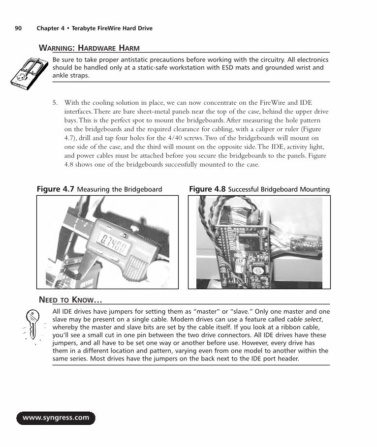
WARNING: HARDWARE HARM
Be sure to take proper antistatic precautions before working with the circuitry. All electronicsshould be handled only at a static-safe workstation with ESD mats and grounded wrist andankle straps.
5. With the cooling solution in place, we can now concentrate on the FireWire and IDEinterfaces.There are bare sheet-metal panels near the top of the case, behind the upper drivebays.This is the perfect spot to mount the bridgeboards.After measuring the hole patternon the bridgeboards and the required clearance for cabling, with a caliper or ruler (Figure4.7), drill and tap four holes for the 4/40 screws.Two of the bridgeboards will mount onone side of the case, and the third will mount on the opposite side.The IDE, activity light,and power cables must be attached before you secure the bridgeboards to the panels. Figure4.8 shows one of the bridgeboards successfully mounted to the case.
NEED TO KNOW…All IDE drives have jumpers for setting them as “master” or “slave.” Only one master and oneslave may be present on a single cable. Modern drives can use a feature called cable select,whereby the master and slave bits are set by the cable itself. If you look at a ribbon cable,you’ll see a small cut in one pin between the two drive connectors. All IDE drives have thesejumpers, and all have to be set one way or another before use. However, every drive hasthem in a different location and pattern, varying even from one model to another within thesame series. Most drives have the jumpers on the back next to the IDE port header.
www.syngress.com
90 Chapter 4 • Terabyte FireWire Hard Drive
Figure 4.7 Measuring the Bridgeboard Figure 4.8 Successful Bridgeboard Mounting
287_HRD_HACK_04.qxd 1/14/04 7:42 PM Page 90

6. Set every drive to “cable select” using the jumpers on the back side near the IDE portheader. Install each drive into a tray in the backplanes and slide them in firmly.Then attachthe IDE cables to all the port headers on the back side of the backplane enclosures. Sinceevery device uses cable select, it does not matter which cable end goes where. Connect theFireWire cables from the hub to each bridgeboard. Connect all the Molex power connec-tors to each drive using Y power cables as needed.The FireWire cables and IDE cables areshown in the proper position in Figure 4.9.
By now you will have an incredible cable mess on your hands. Some thought and plan-ning are required to fit everything in such a tight space.After three attempts to get themarranged right, I prefer to think of it as a carefully choreographed symphony of cable. Figure4.10 shows one way to organize the cables.
7. Go ahead and slide the backplane enclosures the rest of the way in, and tighten the screws.Replace the top cover and its screws. Now you may attach the drives to the host computervia FireWire and power up the array.
www.syngress.com
Terabyte FireWire Hard Drive • Chapter 4 91
Figure 4.9 Putting the FireWire Cables inPlace
Figure 4.10 Cables Cables Cables! TheFinished Product with All Cables Attached
287_HRD_HACK_04.qxd 1/14/04 7:42 PM Page 91

Under the Hood: How the Hack WorksThe completed hack will appear as six 200GB drives on the FireWire bus. Using the RAID softwarethat is built into Mac OS X Disk Utility, you can combine all six drives into a striped array (RAIDLevel 0) to form one huge volume. Windows 2000 also has built-in RAID support, but it is notbootable.
RAID 0 is cheap and simple and usually boosts performance. In our case, any single drive is fasterthan FireWire, so there are no speed gains. When your volume is done formatting, it should appear asone drive icon, as shown in Figure 4.11.
NOTE
RAID stands for redundant array of inexpensive drives. Often RAIDs are neither redundantnor inexpensive. Most RAIDs are built into a striped configuration for capacity and perfor-mance, and they usually use the most expensive high-capacity drives available.
Basically, RAID works by breaking up the data into chunks and then writing those chunks to allsix drives simultaneously. However RAID 0 has one fatal flaw—because there is no actual redundancyin RAID 0, if any single drive fails, the entire array is lost. For this reason it’s only good for things likesystem backups or audio/video servers to store soft copies of media you already own.An array likethis should not be used to store critical data.
www.syngress.com
92 Chapter 4 • Terabyte FireWire Hard Drive
Figure 4.11 The Finished Product: Big Honking Drive with 1.2TB of Capacity
287_HRD_HACK_04.qxd 1/14/04 7:42 PM Page 92

NOTE
RAID 0 is used extensively for storage of video files during editing and in many home com-puters. It gives a speed boost and has only one logical volume to deal with. Given the enor-mous cost of real RAID controllers and the incredible reliability of modern drives, RAID 0 isgreat for many uses provided that the user understands the risks involved. RAID 5 is the typepeople use when data integrity is more important than speed or capacity. The cost of a RAID5 controller puts it out of the grasp of home users.
For around $2,000, a hardware RAID controller can be added to the drive enclosure to performRAID 5.The usable space on the array will shrink by 20 percent, but the array will continue to func-tion even if one drive fails. In RAID 5, data is split into chunks where the data would be written tofive of the six drives and a calculated CRC value written to the sixth drive. Each time a new chunk iswritten, a different drive is used to store the CRC value. RAID 5 currently requires an excessiveamount of processing power for the host computer to perform the calculations at an acceptable speed,which is why it requires using an external RAID controller.
For visual readers, Figure 4.12 shows a block diagram of how the devices should all be connected,illustrating the progression from the FireWire hub to the IDE bridge boards and then to the drives.
www.syngress.com
Terabyte FireWire Hard Drive • Chapter 4 93
Figure 4.12 Functional Block Diagram
FireWire Hub
IDE Bridge IDE Bridge IDE Bridge
HD 1
HD 2
HD 3
HD 4
HD 5
HD 6
287_HRD_HACK_04.qxd 1/14/04 7:42 PM Page 93

Custom Case Modification for the FireWire RAIDA terabyte drive deserves a cool case. Generic beige boxes, although inexpensive, lack the flair andcommanding presence that a project of this nature demands. In this hack I set out to take somethinguninteresting (the plain beige box) and create a personal work of art that would showcase my accom-plishment and not only make the project a conversation piece because of its internals but for itsexternal appearance as well.
Preparing for the HackBefore embarking on the journey of a case modification, you should spend serious time consideringthe aesthetic and artistic aspects of the finished product.Try to imagine how it will look on comple-tion. Consider different colors, designs, and lighting placements before buying any supplies. Don’t beafraid to be daring with your designs, but don’t let the design elements clash with each other in a waythat could be distracting or even worse … garish (unless, of course, that is your intent).
Since the acts of painting, drilling, and cutting are very messy, it is imperative that you prepareyour workspace by, at a minimum, setting down newspapers. However, we recommend using a dropcloth for more thorough protection. It is also recommended (but not required) that you invest in asmall handheld vacuum cleaner to clean up metal or plastic filings that have a tendency to accumulateduring case modifications.The last thing you want is the interior of your case to be contaminatedwith these filings!
The parts required for this particular case modification are presented in Table 4.3.The tools you’llneed are listed in Table 4.4.
Table 4.3 Required Components for the Custom Case Modification
Component Notes
16 oz. of paint that adheres to your materials Thousands of kinds of paint are available formetal in every delivery method imaginable. Dueto the artistic nature of this mod, we leave it upto you to select a paint that suits the effect youare trying to achieve. The paint I used did notstick to metal very well and is now chipping off
Two 12-inch cold cathode lights Color of your choiceTwo 6-inch cold cathode lights Color of your choiceFour cold cathode inverters Matched for the tubesSmall 18–26 AWG wire Preferably red and black wires. The length of the
wires will vary with each implementation,depending on your needs
Small heat-shrink tubingPlexiglas round, 0.1-inch thick Available at TAP Plastics, www.tapplastics.com
www.syngress.com
94 Chapter 4 • Terabyte FireWire Hard Drive
Continued
287_HRD_HACK_04.qxd 1/14/04 7:42 PM Page 94

Table 4.3 Required Components for the Custom Case Modification
Component Notes
Plexiglas sheet, 0.1-inch thick Available at TAP Plastics, www.tapplastics.comE6000 industrial adhesive Available at TAP Plastics, www.tapplastics.comFive T1-size LEDs Various colors of your choice. LED size may also
vary depending on the case you are using, soverify your size requirements before purchasing
Spray contact adhesiveDouble-sided foam tape
Table 4.4 Required Tools for the Custom Case Modification
Tool Notes
Phillips head screwdriver Dremel rotary tool Small carbide cutting bit for Dremel rotary tool Available at most hardware stores, carbide bits
are for metal; however, your exact needs will varydepending on the design you want to cut
Wire cuttersSoldering iron and solderHalf round bastard file Coarse metal fileFine metal files Various shapes and sizesSandpaper Various grit
Performing the HackStart by removing the outer case panels and bezels to be painted. Even the power button should comeout. Most case bezels are held on by two or three screws and two to six plastic hooks just inside thecase.The power button is usually held by four plastic hooks into the front bezel.
1. Before the case painting can start, we need to cut a custom case window. For this case mod-ification I decided that since this was a FireWire case, it should have a FireWire logo on topas its window. Obtaining the artwork for the logo was easy; scalable EPS art is available forfree download from Apple Computer’s Web site.Then it was just a matter of scaling it to theright size and printing it.This created a stencil for my case window.
2. Next, glue the stencil onto the surface of the metal so it will serve as a template when youbegin cutting.You can see the stencil glued to the top of the case in Figure 4.13.
www.syngress.com
Terabyte FireWire Hard Drive • Chapter 4 95
287_HRD_HACK_04.qxd 1/14/04 7:42 PM Page 95

WARNING: PERSONAL INJURY
Always wear eye protection and other safety gear when using power tools. Beware of hottools and surfaces.
3. Let the cutting begin! Drill pilot holes into the metal to allow room for the carbide cuttingbit to fit (see Figure 4.13). Never attempt to use a carbide cutting bit as a drill, because itmay slip off its course and damage the surface.
4. Once the pilot holes are drilled, carefully start cutting using the Dremel tool and carbidecutting bit.This is a very slow and laborious process. Cutting too fast will overheat the bitand may damage it. Smaller bits cut faster but are harder to control.A jigsaw tool works wellfor removing large areas of metal quickly. However, it is critically important not to cutbeyond the edges of your template. Once the metal is cut away, it’s gone forever (unless youare very skilled at repair and touchup). Figure 4.14 shows the cutting process.The finalrough-cut product should look something like Figure 4.15.
www.syngress.com
96 Chapter 4 • Terabyte FireWire Hard Drive
Figure 4.13 Template With Pilot Holes and Initial Cuts
287_HRD_HACK_04.qxd 1/14/04 7:42 PM Page 96

5. A cutting bit and power tools cannot give you the fine detail that you need to make yourcase window look respectable, because they are too hard to control precisely. Now, grab yourcoarse file and start filing.A half round bastard file is great for doing both flat and roundsurfaces. Even with a coarse file, it might take several hours to make the holes smooth.When the edges are the correct size and shape, switch to a finer, smaller file and make everyedge clean and smooth (see Figure 4.16).You should be able to run your fingers over everyedge without fear of cuts or snags.
6. Remove the paper template and sand every surface. Start with coarse sandpaper and workdown to finer grits. If you are cutting plastic, it will only need a quick pass with fine-gritpaper, since plastic is generally a very soft material. Metal, especially painted metal, should besanded down as close to the bare metal as practical or the new paint might not adhere properly.
www.syngress.com
Terabyte FireWire Hard Drive • Chapter 4 97
Figure 4.14 Cutting Along the Template Figure 4.15 Rough Cut of the TemplateUsing the Dremel and Carbide Cutting Bit
Figure 4.16 Rough Cut After Filing
287_HRD_HACK_04.qxd 1/14/04 7:42 PM Page 97

7. Sanding is an important step because the surface smoothness directly impacts the quality ofthe finish after painting. If the surface is rough, the final product will also look rough.Thesmoother, the better.After sanding, wipe every surface with rubbing alcohol, then a drytowel.This will remove the dust and particles from your soon-to-be painted surfaces.Analcohol sweep also removes any remaining mold release agent from cast-plastic parts.
WARNING: PERSONAL INJURY
Always paint in a well-ventilated, dust-free area. Paint fumes are flammable and hazardousto your health. Read and obey all directions and warnings included with your paint products.
WARNING: HARDWARE HARM
If you’re using spray paint, be sure to cover or protect any nearby items that you do notwant to get sprayed. If used improperly, spray paint can cover an entire room with a finemist of pigment.
Always verify material compatibilities when you select paints. Some plastic paints will notstick to metal, and many metal paints will melt plastic. You might want to test your specificpaint on a nonvisible or small section of the case before painting the entire surface.
8. After putting down a large area of newspaper (at least 5 feet by 5 feet), begin spraying thecase, bezel, and any other parts that require painting. If your metal paint requires a primer,apply it before applying the actual coat of paint. Patience is very important at this step.Thebest-quality finishes are made with numerous fine coats of paint. Hold the spray can approx-imately 10 inches away from your surface, and paint across in wide, sweeping strokes.Thefirst few coats will not completely cover the surface.That’s okay.Allow each coat 5 minutesto dry before applying the next coat. When applied thinly, the coats of paint will dry fairlyquickly.
Another good technique for consistent paint delivery is nozzle control. During thesweep, depress the nozzle to spray before reaching the surface, and hold it down past the endof the surface.Although this technique wastes a little bit of paint, it gives you far betterdeposition consistency because spray cans tend to shoot blobs out at the start and sputterwhen the nozzle is released. When the final coat is applied, set the parts aside and let themdry for at least 24 hours. Polymerizing paints should dry for at least seven days without anyhandling. Figure 4.17 shows a completed paint job of the case’s front panel and powerbutton.
www.syngress.com
98 Chapter 4 • Terabyte FireWire Hard Drive
287_HRD_HACK_04.qxd 1/14/04 7:42 PM Page 98

9. To maintain the proper airflow as it was intended for your case, any holes that you cut forwindows must be covered by a transparent material such as polycarbonate or glass. For myFireWire logo, I went to my local TAP Plastics and purchased a 5 × 7-inch sheet of 1/16-inchclear Lexan and glued it into the inside of the case with E6000 industrial adhesive, as shown inFigure 4.18. Make sure that your plastic does not interfere with internal structural componentsof the case. Most plastics come with a protective film layer on each surface.To keep yourplastic clean and scratch free, leave the film in place until you are ready to glue it in.
10. The FireWire logo has a floating circle in the middle. For that reason, I purchased a 1.25-inch round that was 0.1 inches thick. Figure 4.19 shows the plastic sheet with the protectivefilm and the round sitting on top of it.
www.syngress.com
Terabyte FireWire Hard Drive • Chapter 4 99
Figure 4.17 Painted Front Panel and Power Button
Figure 4.18 Plastic Sheet Covering the Inside of the Cutout
287_HRD_HACK_04.qxd 1/14/04 7:42 PM Page 99

11. When the window fits to your satisfaction, glue it down and place a heavy object on it.With the additional weight, the glue will harden thinner and stronger, leaving you with amore durable and visually appealing bond. While the glue is drying, we can begin to workon the lighting.
12. This case has numerous other holes in the front and rear that we can take advantage of forcool lighting effects. For the maximum lighting effect, I purchased four cold cathode fluo-rescent lighting (CCFL) tubes. CCFL lights are much brighter than electro-luminescent(EL) lighting, and they are even visible in a photo taken using a camera flash!
I installed two 6-inch tubes straddling the window (see Figure 4.20) and two 12-inchtricolor CCFL tubes along the bottom of the case (see Figures 4.21 and 4.22). By selectingtubes of different colors, you can create visually interesting lighting and blending effects. Forexample, a red light near a blue light will appear to have a purple region between them.Primary color spectral highlights will appear randomly among reflective surfaces as well. Usedouble-sided foam tape to hold the CCFL lamps in place.
www.syngress.com
100 Chapter 4 • Terabyte FireWire Hard Drive
Figure 4.19 The Window Elements
287_HRD_HACK_04.qxd 1/14/04 7:42 PM Page 100

www.syngress.com
Terabyte FireWire Hard Drive • Chapter 4 101
Figure 4.20 Lamp Placements, Top
Figure 4.21 Lamp Placements, Left Side
287_HRD_HACK_04.qxd 1/14/04 7:43 PM Page 101

13. All CCFL tubes require high-voltage inverters to illuminate.This high voltage is createdusing a special CCFL inverter, which usually requires a standard 12VDC input. Lucky forus, 12V is common on all PC power supply cables. Solder the inverter power leads to theyellow +12 volt and black ground wires coming out of the case power supply and put heat-shrink tubing over the joints to protect and insulate them.
WARNING: HARDWARE HARM
Never apply power to an inverter without a lamp attached to its output. Doing so candamage the inverter.
WARNING: PERSONAL INJURY
Inverters generate extremely high voltages that are very dangerous and can be deadly. TheCCFL inverters generate between 3,000 and 15,000 volts. Never wear ESD protection whilehandling inverters or lamps. A fatal electrocution hazard may exist if a conductive pathacross the heart is established.
14. Simply mount the inverter(s) with double-sided foam tape to a suitable location inside thecase and connect the power. Figure 4.23 shows a dual-output inverter tucked between a fanand a power supply.
www.syngress.com
102 Chapter 4 • Terabyte FireWire Hard Drive
Figure 4.22 Lamp Placements, Right Side
287_HRD_HACK_04.qxd 1/14/04 7:43 PM Page 102

15. The final lighting mod involves replacing the original yellow and green LEDs on the frontof the case with something a little more interesting, colorful, and unique.This case uses T1-sized (3mm) LEDs to show hard drive activity and power.The IDE backplanes have theirown set of LEDs, which I decided not to replace for this hack. I used an ultrabright greenLED for power and patriotic red, white, and blue LEDs for the activity outputs of the threeFireWire bridgeboards.This case uses friction-fit LED sockets, so no soldering was required.However, there are multiple examples of soldered LED replacement hacks throughout thisbook, so fear not if your project entails something a bit more complicated. LEDs are polaritysensitive and will not function if installed backward.The disconnected LEDs on the frontpanel are shown in Figure 4.24 The new LEDs are shown in Figure 4.25.
www.syngress.com
Terabyte FireWire Hard Drive • Chapter 4 103
Figure 4.23 High-Voltage Inverter
287_HRD_HACK_04.qxd 1/14/04 7:43 PM Page 103

www.syngress.com
104 Chapter 4 • Terabyte FireWire Hard Drive
Figure 4.24 New LEDs Replace the Originals on the Front Panel
Figure 4.25 LEDs when Lit
287_HRD_HACK_04.qxd 1/14/04 7:43 PM Page 104

16. Hopefully by now all your paints and glues are fully dry. Go ahead and put the painted frontbezel and power button back onto the enclosure. Snap the locking tabs down firmly, andreplace the bezel retaining screws. Did you peel off the protective film from the windowyet? Next, carefully slide the case back on and tighten the back panel screws.A fabricwasher placed underneath each screw will prevent the screws from gouging the paint. Withthe unit fully assembled, move it to its new home on a solid, level surface. Expect the fullyassembled unit to be very heavy. Mine weighs around 40 pounds.
Under the Hood: How the Hack WorksThroughout this chapter, we covered various elements of case modifications, including case windowcreation, painting, custom lighting, and LED replacement. Until you put the finished producttogether, it is sometimes difficult to guess how it will turn out. Figure 4.26 shows a picture of thefinal hack.
www.syngress.com
Terabyte FireWire Hard Drive • Chapter 4 105
Figure 4.26 Breathtaking View of the Final Hack
287_HRD_HACK_04.qxd 1/14/04 7:43 PM Page 105

With 12 watts of cold cathode lighting coming from four different angles, multicolored lightescapes from every crevice, seam, joint, and gap on this box. Creating a work of art involves attentionto detail and completeness in design. Leave no surface unmodified and no cavity void of lighting.Don’t worry about tiny flaws; most people will never notice them.This hack works because the col-oring and lighting are so fantastic and the fans so quiet that viewers can only sit back in awe, silencedby its splendor. Figures 4.27 though 4.30 show various other views of the completed hack.
www.syngress.com
106 Chapter 4 • Terabyte FireWire Hard Drive
Figure 4.27 Another View
287_HRD_HACK_04.qxd 1/14/04 7:43 PM Page 106

www.syngress.com
Terabyte FireWire Hard Drive • Chapter 4 107
Figure 4.28 Another View
Figure 4.29 Another View
287_HRD_HACK_04.qxd 1/14/04 7:43 PM Page 107
Additional ResourcesThe following is a list of vendors for hardware hacking materials and parts:
Digi-Key Corporation: www.digikey.com
Tap Plastics: www.tapplastics.com
Panasonic Fans: www.panasonic.com/industrial/appliance/appliance_fans_panaflo_axial.htm
FireWire Depot: www.fwdepot.com
Case Mod Supplies: www.xoxide.com
Directron.com: www.directron.com/mods.html
www.syngress.com
108 Chapter 4 • Terabyte FireWire Hard Drive
Figure 4.30 FireWire Logo
287_HRD_HACK_04.qxd 1/14/04 7:43 PM Page 108

Case ModificationsIf you’re looking for ideas, inspiration, or other case modders, these sites are a great place to begin:
Mini-motherboards: www.mini-itx.com
The Ultimate Computer Case Mod Web site: www.thebestcasescenario.com
Case mods, PimpRig: Smack Ya Rig Up!, www.pimprig.com
Case mods, Lucent Rigs: www.lucentrigs.com
Case mods, Pyramac, BlueIce G4, Mac Mods, riscx.com: www.riscx.com/pyramac
www.syngress.com
Terabyte FireWire Hard Drive • Chapter 4 109
287_HRD_HACK_04.qxd 1/14/04 7:43 PM Page 109

287_HRD_HACK_04.qxd 1/14/04 7:43 PM Page 110
Macintosh
Hacks in this Chapter:
Building the Compubrick SE
Building a UFO Mouse
Power Macintosh G4 Cube Hacks
Chapter 5
111
287_HRD_HACK_05.qxd 1/14/04 7:03 PM Page 111
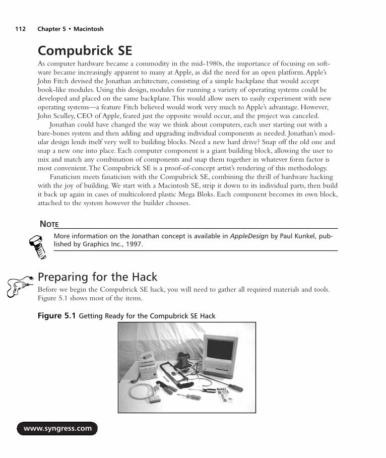
Compubrick SEAs computer hardware became a commodity in the mid-1980s, the importance of focusing on soft-ware became increasingly apparent to many at Apple, as did the need for an open platform.Apple’sJohn Fitch devised the Jonathan architecture, consisting of a simple backplane that would acceptbook-like modules. Using this design, modules for running a variety of operating systems could bedeveloped and placed on the same backplane.This would allow users to easily experiment with newoperating systems—a feature Fitch believed would work very much to Apple’s advantage. However,John Sculley, CEO of Apple, feared just the opposite would occur, and the project was canceled.
Jonathan could have changed the way we think about computers, each user starting out with abare-bones system and then adding and upgrading individual components as needed. Jonathan’s mod-ular design lends itself very well to building blocks. Need a new hard drive? Snap off the old one andsnap a new one into place. Each computer component is a giant building block, allowing the user tomix and match any combination of components and snap them together in whatever form factor ismost convenient.The Compubrick SE is a proof-of-concept artist’s rendering of this methodology.
Fanaticism meets fanaticism with the Compubrick SE, combining the thrill of hardware hackingwith the joy of building. We start with a Macintosh SE, strip it down to its individual parts, then buildit back up again in cases of multicolored plastic Mega Bloks. Each component becomes its own block,attached to the system however the builder chooses.
NOTE
More information on the Jonathan concept is available in AppleDesign by Paul Kunkel, pub-lished by Graphics Inc., 1997.
Preparing for the HackBefore we begin the Compubrick SE hack, you will need to gather all required materials and tools.Figure 5.1 shows most of the items.
www.syngress.com
112 Chapter 5 • Macintosh
Figure 5.1 Getting Ready for the Compubrick SE Hack
287_HRD_HACK_05.qxd 1/14/04 7:03 PM Page 112

Macintosh • Chapter 5 113
Table 5.1 is a list of components that you will need to build a Compubrick SE.
Table 5.1 Required Components for the Compubrick SE
Component Notes
Macintosh SE800K external drive Model number M0131Mega Bloks, about 2,500 A few of Mega Bloks’ 600-piece bins will work. Be
careful when estimating the number you’ll need;many of the smaller pieces won’t be usable in thisproject.
Erector setInternal-to-external SCSI cable Found in external hard drivesSCSI terminator18-22AWG wire, 26 feet
Table 5.2 presents a list of tools that you will also need to build a Compubrick SE.
Table 5.2 Required Tools for the Compubrick SE
Tool Notes
Super GlueT15 x 6 in. screwdriver Sears Craftsman part #47431Straight screwdriverPhilips screwdriverWire stripper/crimper Found in external hard drivesWire snips or hobby knifeViseHacksaw
A Craftsman T15 x 6 in. screwdriver is available at Sears for under $5.A longer shaft is convenientbut not necessary. Mega Bloks and Erector sets can be found at any toy store.Try salvaging aninternal-to-external SCSI cable from an old external hard drive. Computer swap meets will oftenhave used hard drives, disk drives, and the Mac SE for pennies on the dollar. If you’re not inclined togo searching, you can easily purchase all these components online for a few dollars plus the cost ofshipping. Here are a few sources to consider:
eBay: www.ebay.com
USENET Groups: groups.google.com
Applefritter Forums: www.applefritter.com
www.syngress.com
287_HRD_HACK_05.qxd 1/14/04 7:03 PM Page 113

Performing the HackThe disassembly and reassembly of the Compubrick is a multistep process.To make this process easierto understand, we have broken the hack into different modules, as follows:
Taking Apart the Mac
Speaker
Keyboard and Mouse
Disk Drive
Hard Drive
Motherboard
Cathode Ray Tube (CRT)
Taking Apart the MacSteve Jobs saw the Macintosh as an appliance not meant to be taken apart.As such, the compact Macsare very difficult to open. In order to disassemble the Mac, complete the following steps:
1. Locate the four T15 Torx screws that need to be removed.Two are on the back, just abovethe line of ports.The other two are inside the handle, for which the long screwdriver shaft isnecessary.You can see the removal process for the screws inside the handle in Figures 5.2and 5.3.
2. Once you have removed the screws, pry open the case by gently tugging at each corner ofthe case until the two pieces separate (see Figure 5.4).
www.syngress.com
114 Chapter 5 • Macintosh
Figure 5.2 Locations of Screws Figure 5.3 Unscrewing the Screws
287_HRD_HACK_05.qxd 1/14/04 7:03 PM Page 114

Macintosh • Chapter 5 115
3. Once the case is open, discharge the CRT.This is a dangerous and critical step.
WARNING: PERSONAL INJURY
The CRT inside a compact Macintosh can potentially hold a charge of up to 13,000 volts,which can give you quite a shock. Take extreme caution to discharge the CRT properly. Anexample of discharge procedure can be found at www.jagshouse.com/CRT.html. Never per-form a CRT discharge alone—always have a friend present in case of emergency.
4. Next, remove the analog cable from the motherboard. Figure 5.5 shows a photo of theinside of the Mac with the analog cable in place.The cable is a snug fit; be careful not tobump the CRT’s neck when the cable gives way, because it could easily snap off and destroythe monitor!
www.syngress.com
Figure 5.4 Prying the Case Apart
Figure 5.5 Inside the Mac SE with the Analog Cable in Place
287_HRD_HACK_05.qxd 1/14/04 7:03 PM Page 115

5. Now slide the motherboard upward about an inch and pop it out (see Figure 5.6).
With the case opened, we can now begin to dismantle the chassis:
1. Remove the two screws (shown in Figure 5.7) that hold the hard drive and floppy enclosurein place.The drive unit will now easily lift out of the case and can be set aside.
2. Next, detach the frame from the front cover.The frame has five screws holding it in place;four of these screws are pictured in Figure 5.8.
www.syngress.com
116 Chapter 5 • Macintosh
Figure 5.6 Removing the Motherboard
Figure 5.7 Hard Drive Screws
287_HRD_HACK_05.qxd 1/14/04 7:03 PM Page 116

3. To be able to remove the fifth screw that attaches the front cover, we have to first detach thepower supply, which is mounted to the analog board with six screws on its right side.
NEED TO KNOW…The analog board is the circuit board mounted vertically beside the power supply. It providespower to the CRT and motherboard.
4. Push the power supply out of the way, as shown in Figure 5.9, to reach the last screw.
www.syngress.com
Macintosh • Chapter 5 117
Figure 5.8 Frame Screws: Four of the Five
Figure 5.9 Removing the Fifth Frame Screw
287_HRD_HACK_05.qxd 1/14/04 7:03 PM Page 117

5. With the frame now disconnected, lift it out of the case and set it aside (see Figure 5.10).
6. Next, remove the power supply after disconnecting it from the analog board. Disconnect theshort cable that connects the CRT to the analog board (see Figure 5.11).This allows you tospread out the remaining parts as shown in Figure 5.12.
7. Finally, disconnect the CRT from the front plate by removing the four screws, one in eachcorner of the CRT.This is done so that you can remove the speaker from the front case.Thespeaker is held in place by two flimsy plastic tabs, as shown in Figure 5.13. Just break theseoff using the wire snips or a hobby knife.
www.syngress.com
118 Chapter 5 • Macintosh
Figure 5.10 Frame Removed from the Case
Figure 5.11 Disconnect the Power Supply Figure 5.12 The Analog Board
287_HRD_HACK_05.qxd 1/14/04 7:03 PM Page 118

NEED TO KNOW… BUILDING TECHNIQUES
The Compubrick design is based primarily upon the use of 2x4 bricks, making flat regions abit tricky because the block segments are so short. These regions are built using two layersof bricks, with the second layer offset from the first, as shown in Figures 5.14 and 5.15. Thistechnique is known as layering.
Assembling the bricks in this manner is adequate for use on small surfaces such as thetop or bottom of the hard drive or disk drive. For the larger areas, however, this techniqueresults in a connection that is too flimsy. In this case, it is necessary to reinforce the assemblywith Super Glue. Figure 5.16, the top of the CRT case, is an example of an area so large thatit requires gluing for strength. Place a dab of glue on the edges of a few studs on the brick,then quickly snap the piece above it into place. Avoid placing glue on the sides of the bricks.It will seep out when you press them together.
www.syngress.com
Macintosh • Chapter 5 119
Figure 5.13 Moving the Speaker
Figure 5.14 Mega Blok Layering Example,Underside
Figure 5.15 Mega Blok Layering Example,Top
287_HRD_HACK_05.qxd 1/14/04 7:03 PM Page 119

Encasing the SpeakerThe first task of assembling the Compubrick is constructing the speaker encasement.This is a rela-tively simple step.You need to encase the speaker with blocks, using cylindrical 1x1s for the speakergrill.Any color or size brick that you prefer to use is acceptable; however, the case should be relativelythe same size as the example shown in Figure 5.17.
A completed version of the speaker encased in blocks is shown in Figure 5.18.
www.syngress.com
120 Chapter 5 • Macintosh
Figure 5.16 Mega Blok Layering Example, Top of the CRT Case
Figure 5.17 Partially Assembled Speaker
Figure 5.18 Completed Speaker
287_HRD_HACK_05.qxd 1/14/04 7:03 PM Page 120
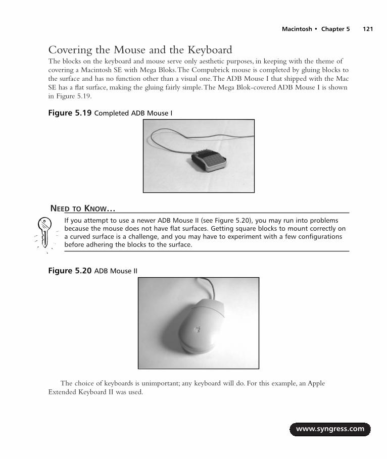
Covering the Mouse and the KeyboardThe blocks on the keyboard and mouse serve only aesthetic purposes, in keeping with the theme ofcovering a Macintosh SE with Mega Bloks.The Compubrick mouse is completed by gluing blocks tothe surface and has no function other than a visual one.The ADB Mouse I that shipped with the MacSE has a flat surface, making the gluing fairly simple.The Mega Blok-covered ADB Mouse I is shownin Figure 5.19.
NEED TO KNOW…If you attempt to use a newer ADB Mouse II (see Figure 5.20), you may run into problemsbecause the mouse does not have flat surfaces. Getting square blocks to mount correctly ona curved surface is a challenge, and you may have to experiment with a few configurationsbefore adhering the blocks to the surface.
The choice of keyboards is unimportant; any keyboard will do. For this example, an AppleExtended Keyboard II was used.
www.syngress.com
Macintosh • Chapter 5 121
Figure 5.19 Completed ADB Mouse I
Figure 5.20 ADB Mouse II
287_HRD_HACK_05.qxd 1/14/04 7:04 PM Page 121

1. Dismantle the keyboard by removing both the top and bottom pieces of the case.The topand bottom of the keyboard case is usually connected by a variety of simple screws that canbe accessed from the bottom of the keyboard. In the case of the Extended Keyboard II,there is only one screw (see Figure 5.21). Remove it, then pry the keyboard apart.
2. Now remove the keyboard mechanism from the case (see Figure 5.22).To do this, firstrelease the keyboard from underneath the snaps, then pop out the ADB connectors. Finally,slide the keyboard upward out of the tabs. Once you have separated the top and bottomportions of the keyboard case, discard the top piece.
3. Next, take the bottom half of the keyboard and, using the hacksaw, saw off any tabs thatprotrude from the case (Figure 5.23).This is done so you have as smooth a surface as pos-sible on which to place the bricks.
www.syngress.com
122 Chapter 5 • Macintosh
Figure 5.21 Bottom of KeyboardFigure 5.22 Removing the KeyboardMechanism
Figure 5.23 Sawing Off the Tabs
287_HRD_HACK_05.qxd 1/14/04 7:04 PM Page 122

4. Now place the keyboard back into the lower case and build your frame around it, filling inthe spaces between rows of keys with blocks (see Figure 5.24). When you have a frame thatyou’re happy with, remove it, apply glue to the keyboard, and press the frame into place.Thefinished keyboard will resemble Figure 5.25.
Encasing the Disk DriveTo encase the disk drive with the Mega Bloks, you will first have to remove the disk drive from itsplastic case, but keep the metal chassis and cable intact.
1. There are four screws on the bottom of the case (see Figure 5.26). Remove these, andremove the bottom piece of plastic.
www.syngress.com
Macintosh • Chapter 5 123
Figure 5.24 Partially Assembled Keyboard Figure 5.25 Completed Keyboard
Figure 5.26 Bottom of the Floppy Drive
287_HRD_HACK_05.qxd 1/14/04 7:04 PM Page 123
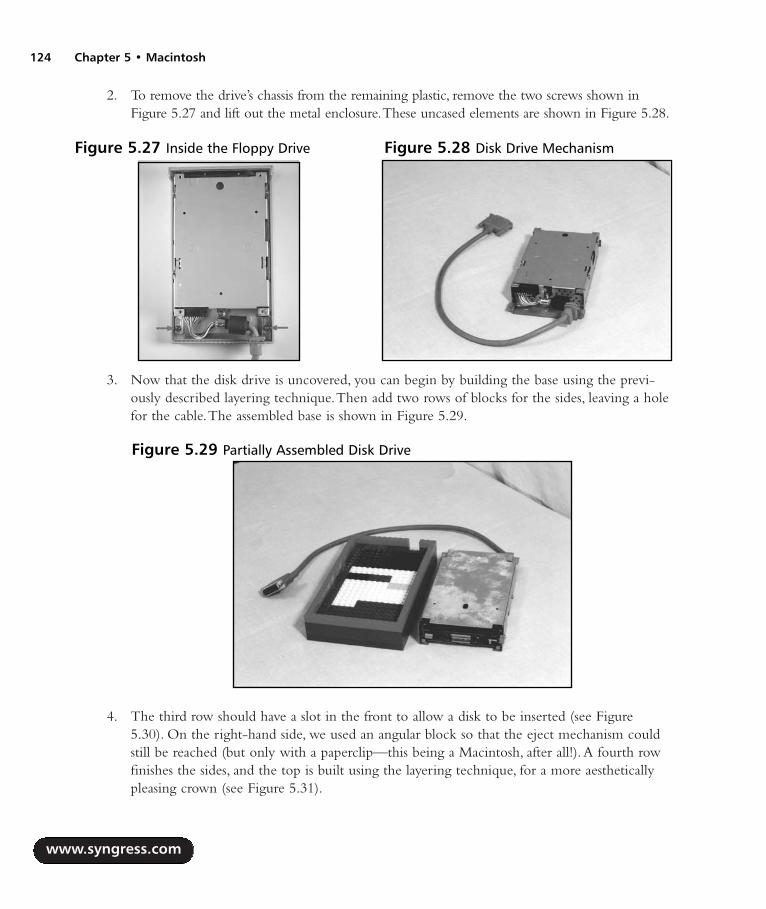
2. To remove the drive’s chassis from the remaining plastic, remove the two screws shown inFigure 5.27 and lift out the metal enclosure.These uncased elements are shown in Figure 5.28.
3. Now that the disk drive is uncovered, you can begin by building the base using the previ-ously described layering technique.Then add two rows of blocks for the sides, leaving a holefor the cable.The assembled base is shown in Figure 5.29.
4. The third row should have a slot in the front to allow a disk to be inserted (see Figure5.30). On the right-hand side, we used an angular block so that the eject mechanism couldstill be reached (but only with a paperclip—this being a Macintosh, after all!).A fourth rowfinishes the sides, and the top is built using the layering technique, for a more aestheticallypleasing crown (see Figure 5.31).
www.syngress.com
124 Chapter 5 • Macintosh
Figure 5.27 Inside the Floppy Drive Figure 5.28 Disk Drive Mechanism
Figure 5.29 Partially Assembled Disk Drive
287_HRD_HACK_05.qxd 1/14/04 7:04 PM Page 124

Encasing the Hard DriveThe goal of this step is to remove the SCSI internal hard drive from your Mac SE and create anexternal, modular SCSI drive.To do this:
1. Take the hard drive out of your Mac SE (or use any other SCSI hard drive) and theinternal-to-external SCSI cable you salvaged from the external hard drive.
2. Connect them together, and then connect the SCSI cable and terminator. Now build thebase and the top using layering, and build up the sides around the drive and cables, as shownin Figure 5.32.
3. If you used a cable and terminator as shown in Figure 5.32, you’ll find that the two stackedcomponents are just barely too high to allow the top to fit on.The difference is slightenough that shaving a layer of plastic off the SCSI terminator will allow everything to fitproperly, so stick the terminator in a vice and grab a hacksaw (see Figure 5.33).
www.syngress.com
Macintosh • Chapter 5 125
Figure 5.30 Eject Mechanism Figure 5.31 Completed Disk Drive
Figure 5.32 Partially Assembled Hard Drive
287_HRD_HACK_05.qxd 1/14/04 7:04 PM Page 125

Figures 5.34 and 5.35 show the finished product: a nice square unit with the cables neatly pro-truding from the back.
www.syngress.com
126 Chapter 5 • Macintosh
Figure 5.33 Hacksawing the SCSI Terminator
Figure 5.34 Completed Hard Drive, Front Figure 5.35 Completed Hard Drive, Back
287_HRD_HACK_05.qxd 1/14/04 7:04 PM Page 126
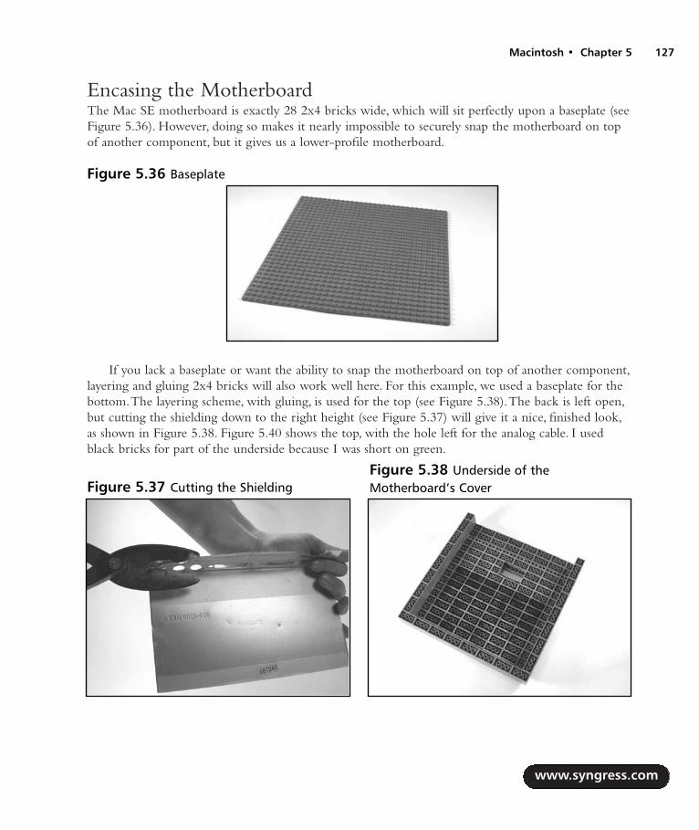
Encasing the MotherboardThe Mac SE motherboard is exactly 28 2x4 bricks wide, which will sit perfectly upon a baseplate (seeFigure 5.36). However, doing so makes it nearly impossible to securely snap the motherboard on topof another component, but it gives us a lower-profile motherboard.
If you lack a baseplate or want the ability to snap the motherboard on top of another component,layering and gluing 2x4 bricks will also work well here. For this example, we used a baseplate for thebottom.The layering scheme, with gluing, is used for the top (see Figure 5.38).The back is left open,but cutting the shielding down to the right height (see Figure 5.37) will give it a nice, finished look,as shown in Figure 5.38. Figure 5.40 shows the top, with the hole left for the analog cable. I usedblack bricks for part of the underside because I was short on green.
www.syngress.com
Macintosh • Chapter 5 127
Figure 5.36 Baseplate
Figure 5.37 Cutting the ShieldingFigure 5.38 Underside of theMotherboard’s Cover
287_HRD_HACK_05.qxd 1/14/04 7:04 PM Page 127

Figure 5.40 shows us the completed motherboard case. Note the hole left for the analog cable,denoted by the arrow.
www.syngress.com
128 Chapter 5 • Macintosh
Figure 5.39 Partially Assembled Motherboard
Figure 5.40 The Finished Motherboard Enclosure
287_HRD_HACK_05.qxd 1/14/04 7:04 PM Page 128

Encasing the CRTMounting the CRT to the analog board is tricky because we’re no longer using the original plasticencasements. We will first use Erector set beams to build a frame across the top and bottom and downthe side of the CRT, then connect it to the analog board using the holes already available (see Figure5.41). Use whatever Erector set pieces you have available to build a frame that extends from the back,affixing to the analog board using the holes already present.Then extend beams from the CRT to thebrackets in the back (see Figure 5.42) Connect the grounding wires (circled in Figure 5.43) anywhereon the frame. Figures 5.43 and 5.44 show the back of the completed CRT and analog board structure.
Since the cable that runs from the analog board to the motherboard must reach outside of yourCRT case, it must be extended.To do this:
1. Cut the cable in half (see Figure 5.45) and use your stripper to bare the edges (see Figure5.46).
2. Then crimp both ends to a new series of wires (see Figure 5.47), each about two feet long.
www.syngress.com
Macintosh • Chapter 5 129
Figure 5.41 CRT and Analog BoardStructure, Front View Figure 5.42 Affixing Erector Set Pieces
Figure 5.43 Completed CRT Structure, TopView
Figure 5.44 Completed CRT Structure,Bottom View
287_HRD_HACK_05.qxd 1/14/04 7:04 PM Page 129
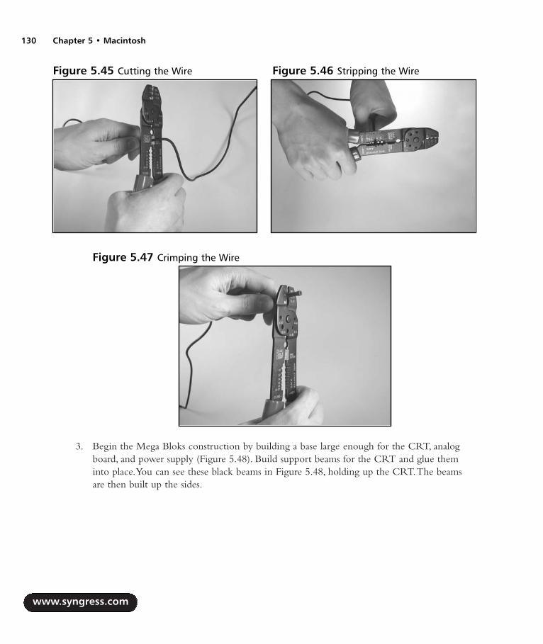
3. Begin the Mega Bloks construction by building a base large enough for the CRT, analogboard, and power supply (Figure 5.48). Build support beams for the CRT and glue theminto place.You can see these black beams in Figure 5.48, holding up the CRT.The beamsare then built up the sides.
www.syngress.com
130 Chapter 5 • Macintosh
Figure 5.45 Cutting the Wire Figure 5.46 Stripping the Wire
Figure 5.47 Crimping the Wire
287_HRD_HACK_05.qxd 1/14/04 7:04 PM Page 130

4. As you build, leave a hole in the front around the contrast knob.You’ll also need to leave ahole in the back for the cable.The cable is already wired into place, so when you reach theheight at which you want it, just build around it. Likewise, build around the power supplyand the fan, so they are even with the back.
5. Build the top using the layering technique (Figure 5.49) and gently snap it into place. Figure5.50 shows an almost complete CRT encasement.
How the Hack WorksNow that we’re finished preparing the individual components, we can snap them together andarrange them in whatever manner you desire. Using a few extra blocks to widen the top of the
www.syngress.com
Macintosh • Chapter 5 131
Figure 5.48 CRT on a Mega Bloks Base
Figure 5.49 Top of the CRT, Built withLayering Figure 5.50 CRT Nearing Completion
287_HRD_HACK_05.qxd 1/14/04 7:04 PM Page 131

Compubrick, we can place the floppy drive and hard drive side by side, as shown in Figure 5.51, orwe can spread everything out, like Figure 5.52.
If we want a compact, minimalist system, the hard drive and speaker can be removed and themotherboard stacked on top of the CRT.The analog cable that comes out of the top of the mother-board prevents us from putting the disk drive directly on top, but a set of legs (in white) for thefloppy drive quickly fixes that problem (see Figure 5.53).
Building a UFO Mouse“Today we brought romance and innovation back into the industry,” Steve Jobs proclaimed as he intro-duced the iMac on May 6, 1998. It was the dawn of a new era for Apple. Gone was SCSI, gone wasADB, and gone was beige. Heralded as the most innovative computer since the original Macintosh, theiMac was as revolutionary in its industrial design as it was in its architecture. Curved sheets of translucent
www.syngress.com
132 Chapter 5 • Macintosh
Figure 5.51 Compubrick SE, PartiallyStacked Setup Figure 5.52 Compubrick SE, Wide Setup
Figure 5.53 Compubrick SE, Minimal Setup
287_HRD_HACK_05.qxd 1/14/04 7:04 PM Page 132

“Bondi Blue” plastics replaced the old beige metal cases with rigid corners.Apple’s new design was aninstant hit, and soon the entire industry was following suit, rounding their corners and making theirplastics translucent. Few matched the elegance of the iMac, with its close attention to detail.
Even the iMac’s mouse sported a unique new design (see Figure 5.54). Perfectly round, the iMacmouse was denounced for its ergonomics but lauded for its style.At the iMac’s introduction, thetranslucent mouse was set upon a lighted pedestal, causing it to glow and leading to rumors themouse itself was lit.The rumors were false but, for the aspiring hacker, inspirational.
The goal of this hack is to modify a standard Apple USB Mouse to add an LED, giving themouse a glowing appearance.
Preparing for the HackThe UFO mouse is a simple hack to perform and requires relatively few parts or tools.A picture ofthe materials is shown in Figure 5.55.The components that you will need outlined in Table 5.3.
www.syngress.com
Macintosh • Chapter 5 133
Figure 5.54 Apple USB Mouse
Figure 5.55 Getting Ready for the UFO Mouse Hack
287_HRD_HACK_05.qxd 1/14/04 7:04 PM Page 133

Table 5.3 Required Components for the UFO Mouse Hack
Component Notes
Apple USB mouse Also known as the “puck mouse”Blue LED Radio Shack Part #276-311, 5V, T1 3/4 size
The tools that are required for this hack are described in Table 5.4.
Table 5.4 Required Tools for the UFO Mouse Hack
Tool Notes
Soldering iron and solderDrill and 7/32-inch drill bitSmall flat-head screwdriverSmall Philips screwdriverSmall jeweler’s screwdriver
As an alternative to the blue LED, Radio Shack also sells a blinking red LED, part #276-036, thatruns off 5V and will work in the mouse. If you want something a bit wilder (and potentially headacheinducing), consider this LED in lieu of the blue one.
Performing the HackBuilding an illuminated puck mouse consists of four steps:
1. Opening the mouse
2. Drilling the hole
3. Soldering the LED
4. Reassembling the mouse
Opening the Mouse1. You’ll see a translucent blue plastic covering on both the right and left sides of the mouse.
To open the mouse, you’ll have to remove this covering.The plastic coverings are eachattached to the body of the mouse with three tabs.The locations of the tabs are shown inFigure 5.56.
www.syngress.com
134 Chapter 5 • Macintosh
287_HRD_HACK_05.qxd 1/14/04 7:04 PM Page 134

2. With a small flat screwdriver, gently pry the two tabs on the mouse’s underside loose andthen wiggle the third one free (see Figure 5.57).
3. With the plastic coverings removed, locate the two screws on the bottom of the mouse thatwere previously hidden (Figure 5.58). Using a small jeweler’s screwdriver, remove these twoscrews and then pry upward on the back end of the plastic casing to remove the top cover.
www.syngress.com
Macintosh • Chapter 5 135
Figure 5.56 Tab Locations on the Plastic Covering
Figure 5.57 Removing the Plastic Coverings
Figure 5.58 Unscrewing the Mouse
287_HRD_HACK_05.qxd 1/14/04 7:04 PM Page 135

Drilling the HoleTo achieve a more diffused glow that really illuminates your puck mouse, you need to drill a hole intothe ball chamber and point the LED into it.
1. Remove the circuit board from the mouse and place it as far away as the cable will allow(see Figure 5.59).
2. Using the 7/32-inch drill bit, drill a hole into the backside of the mouse housing (the sideopposite the button), as indicated by the arrow in Figure 5.59.The hole should be just lowenough so that the rim around the top of the chamber will not be broken.The proper posi-tioning of the drill is shown in Figure 5.60.
www.syngress.com
136 Chapter 5 • Macintosh
Figure 5.59 The Circuit Board Removed from the Case
Figure 5.60 Drilling the Hole
287_HRD_HACK_05.qxd 1/14/04 7:04 PM Page 136

Soldering the LEDNow that the hole is prepared in the plastic mouse housing, it’s time to attach the LED to the mouse.
NEED TO KNOW… LED POLARITY
An LED typically has two leads projecting from its base (see Figure 5.61). The longer lead isthe positive lead (also known as the anode). The shorter lead is the negative lead (alsoknown as the cathode). The cathode is also denoted by a flat edge on the plastic LEDhousing. The anode will connect to a positive voltage (5V in this case) and the cathode willconnect to ground.
1. Turn the mouse so that the cable is facing away from you (Figure 5.62). Opposite the cable,you should notice that there are five pins outlined in white.
www.syngress.com
Macintosh • Chapter 5 137
Figure 5.61 LED Diagram
Figure 5.62 Close-Up of the Pins
287_HRD_HACK_05.qxd 1/14/04 7:04 PM Page 137

2. Snip the leads on the LED so that they are the appropriate length to reach from these pinsinto the hole that you drilled.
3. Now solder the positive lead of the LED to the leftmost pin (Figure 5.63). If you turn thecircuit board over, you’ll see that the wire going into this pin is red.
4. Next, solder the negative lead (the flat side of the LED) to the second pin from the right. Ifyou turn the circuit board over, you’ll see that the wire going into this pin is black.
WARNING: HARDWARE HARM
When soldering the LED to the circuit board, be careful not to heat up the device too muchor cause any surrounding pins to be lifted up or shorted together with solder. The pins arevery close together, and you might want to use a magnifying glass to inspect your work.
Reassembling the MouseNow put your mouse back together:
1. Carefully adjust the head of the LED to stick into the hole you drilled in the plastichousing. Be careful not to snap the LED off the circuit board. Make sure the circuit board isfirmly connected to the base.Two spokes stick up from the base, one in the upper right andone in the lower left. Make sure these spokes go through the appropriate holes in the circuitboard, rather than allowing the board to rest on top of them. When properly aligned, theboard will fit snugly on the posts (see Figure 5.64).
www.syngress.com
138 Chapter 5 • Macintosh
Figure 5.63 Soldering the LED
287_HRD_HACK_05.qxd 1/14/04 7:04 PM Page 138

2. Finally, take the plastic cover and place the tabs on its front into the corresponding slots onthe base.Then snap the backside of the two pieces together (see Figure 5.65).
3. Return the two screws and snap the plastic sides into place.The hack is now complete!
www.syngress.com
Macintosh • Chapter 5 139
Figure 5.64 Properly Aligned Mouse
Figure 5.65 Closing the Mouse
287_HRD_HACK_05.qxd 1/14/04 7:04 PM Page 139

Figure 5.66 shows a picture of the completed UFO mouse in all its glowing glory.
How the Hack WorksThis hack is extremely simple—all we need to do is add an LED onto the circuit board of the USBmouse.The LED receives its power directly from the USB port, which provides a 5VDC supply.TheLED is connected to the power supply using the two pads provided for us on the circuit board. Sincewe are using an LED with a forward voltage of 5V, we do not see a need to include a current-lim-iting resistor. Note that if any other LED is used, you may have to add a current-limiting resistorbetween the 5V supply line from the mouse and the positive lead of the LED—otherwise, you coulddamage the LED when it received power. See the “Electrical Engineering Basics” chapter and otherLED hacks in this book for more details.
Adding Colored Skins to the Power Macintosh G4 CubeOne of the most popular consumer-based Macintosh systems from Apple Computer Inc. was thePower Mac G4 Cube (also known simply as the Cube), announced at MacWorld New York 2001.This machine’s compact size and high CPU power made it an instant hit with users in every marketwho wanted a full-powered desktop computer in a tastefully artistic and compact enclosure.The G4Cube was built to accept many of the same components as a full-size desktop computer, such as 3.5-inch hard disks, standard PC100 memory, and processor expansion cards.
Of course, the big downfall to all modern computer designs is the rapidly changing pace of tech-nology. Eventually a machine, no matter how cool and sexy it is, is overtaken by the next new inter-esting design.Although the G4 Cube’s lifespan far exceeds that of most personal computers, it is truethat this wonderful machine is leaning toward obsolescence. However, a growing community of die-hard Cube fans, including myself, will go to great lengths to keep their machines useful.
www.syngress.com
140 Chapter 5 • Macintosh
Figure 5.66 Completed UFO Mouse
287_HRD_HACK_05.qxd 1/14/04 7:04 PM Page 140

This hack allows you to change the external appearance of your G4 Cube from the original,boring gray to any design you choose.You can make your Cube any color you want. Since the Cubecomes in a gray metal box suspended inside a clear plastic box, any design that can be put to papercan be inlaid inside the cube.
This construction also has the advantage of protecting your artwork from external abrasions dueto handling. However, the clear plastic case is far from scratch proof, so handle with care.
Preparing for the HackTo prepare for this hack, you need to choose the artwork for your case design. Literally thousands ofpublic domain textures are available online for free download, or you could create your own customdesign in any number of art programs, such as Adobe Illustrator.A “wrappable” texture design flowsfrom the edge of one sheet of paper perfectly to the second sheet, creating an appearance of thedesign being on one single, long sheet of paper. Instructions on how to create your own wrappableartwork for your cube are available at www.resexcellence.com/hack_html_00/12-15-00.shtml.
WARNING: HARDWARE HARM
If you decide to print out your own texture, be aware that the pigments printed by thermalprinters (e.g., laser or dye sublimation) can adhere to the plastic shell of the Cube when themachine heats up. This will cause inconsistencies in the appearance of the texture, and if theshell is removed later, the texture will be destroyed. Excess pigment left inside the clear shellcan be removed with rubbing alcohol and a soft cotton cloth.
The parts required for this hack are shown in Table 5.5.
Table 5.5 Required Components for the Colored Skins Hack
Component Notes
Custom texture design Paper design 7.25 inches square, 5 sheets of 8.5 x 11-inch paper
Glossy clear tape Scotch Transparent Tape 600, 1/2-inch widthFelt-tip marker As close to texture color as possible
www.syngress.com
Macintosh • Chapter 5 141
287_HRD_HACK_05.qxd 1/14/04 7:04 PM Page 141

The tools required for this hack are listed in Table 5.6.
Table 5.6 Required Tools for the Colored Skins Hack
Tool Notes
Small Phillips screwdriverScissorsTorx screwdriver, size T-10 Available at most hardware storesX-ACTO knife Cloth gloves Optional—to prevent leaving fingerprints on the
plastic casing
Performing the Hack1. The first step in the hack is to open your G4 Cube by removing the screws that hold the
acrylic cube in place. Remove the Cube core (the actual CPU that sits inside the clear case)and set it aside someplace safe.
2. Inside the shell you will find two Phillips head screws and four T-10 Torx screws (see Figure5.67). Remove all six screws.
3. Next, you must remove the black screen grate that covers the vent slots on top, also shownin Figure 5.67.The easiest way to do this is to unhook the screen and then lift up the shell.The grill should drop away. Once the grill is gone, you can remove the metal shell frominside the plastic shell. Be careful not to touch the inside of the plastic shell unless you’rewearing cloth gloves or you’ll leave fingerprints in it.
www.syngress.com
142 Chapter 5 • Macintosh
Figure 5.67 Screw Locations Inside the G4 Cube
287_HRD_HACK_05.qxd 1/14/04 7:04 PM Page 142
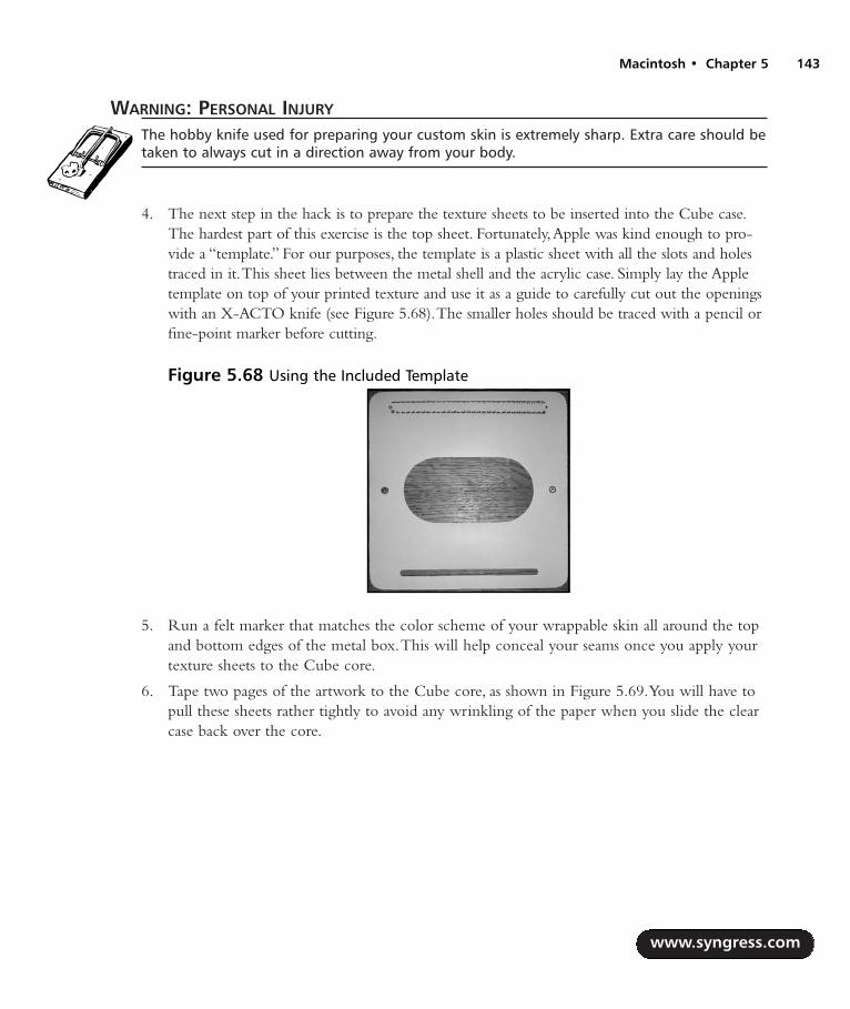
WARNING: PERSONAL INJURY
The hobby knife used for preparing your custom skin is extremely sharp. Extra care should betaken to always cut in a direction away from your body.
4. The next step in the hack is to prepare the texture sheets to be inserted into the Cube case.The hardest part of this exercise is the top sheet. Fortunately,Apple was kind enough to pro-vide a “template.” For our purposes, the template is a plastic sheet with all the slots and holestraced in it.This sheet lies between the metal shell and the acrylic case. Simply lay the Appletemplate on top of your printed texture and use it as a guide to carefully cut out the openingswith an X-ACTO knife (see Figure 5.68).The smaller holes should be traced with a pencil orfine-point marker before cutting.
5. Run a felt marker that matches the color scheme of your wrappable skin all around the topand bottom edges of the metal box.This will help conceal your seams once you apply yourtexture sheets to the Cube core.
6. Tape two pages of the artwork to the Cube core, as shown in Figure 5.69.You will have topull these sheets rather tightly to avoid any wrinkling of the paper when you slide the clearcase back over the core.
www.syngress.com
Macintosh • Chapter 5 143
Figure 5.68 Using the Included Template
287_HRD_HACK_05.qxd 1/14/04 7:04 PM Page 143

7. Apply the two remaining panels for the top and the rear of the Cube core, lining up the edgeswith the front of the Cube. Secure these sheets using a piece of clear tape at least 8 incheslong. Make sure that the ends of the tape are cut with scissors, rather than torn with your fin-gers, to ensure a smooth edge. Make sure to trim any excess tape once you have tightlywrapped the Cube design. Using this method, your seams will be placed on the corners andthus make the seams much less visible. Figure 5.70 shows a close-up of the finished seam.
8. After every sheet is secure, carefully return the wrapped core Cube back into the acrylicshell.You might want to run a clean cloth around the inside of the shell to remove any fin-gerprints or debris.
Once the Cube is fully assembled, your hack is complete! Figure 5.70 shows my personal G4Cube with a custom skin.
www.syngress.com
144 Chapter 5 • Macintosh
Figure 5.69 Applying the Texture Sheets
Figure 5.70 Taping the Seams
287_HRD_HACK_05.qxd 1/14/04 7:04 PM Page 144

Under the Hood: How the Hack WorksAll we are doing for this hack is slipping colored paper between the clear plastic outer shell and thegray metal box of the G4 Cube.The thick plastic causes some interesting visual effects with certainabstract designs, so experiment with various colors and shapes.The protection of the clear shell willkeep your art looking great for years to come. Just be sure to keep your custom Cube away fromdirect sunlight.
Other Hacks and ResourcesThis chapter includes only the beginning of the things that you can do to your Mac.The followingare lists of some of our favorites!
Desktop Hacks Compubrick 160: www.applefritter.com/compubrick/compubrick160 The orig-
inal Mega Blocks Macintosh.
DLZ-3: www.applefritter.com/hacks/dlz3 Devin Durham’s Mac in a 1940’s ZenithRadio case. Note the beautiful CD-ROM drive.
030 MacAquarium: www.applefritter.com/hacks/68Kfish Jeff Knox turned hisSE/30 into an aquarium—and it still runs!
www.syngress.com
Macintosh • Chapter 5 145
Figure 5.71 G4 Cube with a Custom Skin
287_HRD_HACK_05.qxd 1/14/04 7:04 PM Page 145

Duo Digital Frame: www.applefritter.com/hacks/duodigitalframe This eleganthack by James Roos places a Powerbook screen inside a picture frame.
Ze PowerSuitcase: www.applefritter.com/hacks/zepowersuitcase Bernard Bélangerbuilt his Macintosh into a suitcase.
Red Rocket: www.applefritter.com/hacks/redrocket This rugged case was built fromscratch by Mark Fisher to house his Power Mac 7300.
21” iMac: www.applefritter.com/hacks/21imac Don Hardy rebuilt the original iMac,with its 15-inch display, into a 21-inch Nokia monitor.
Laptop Hacks Tron Book: www.applefritter.com/hacks/tronbook icruise stripped the paint off his
iBook with alcohol, then painted the case a translucent blue.
ZebraBook: www.applefritter.com/hacks/zebrabook In this simple hack, MarkHerbert replaced half of his Powerbook’s black keys with white keys from an iBook, creatingan elegant “zebra” effect.
Monster Ti: www.applefritter.com/hacks/monster_ti Ted Warren painted hisPowerbook G4 black, then added flames.
TiDrag: www.applefritter.com/hacks/tidrag Artist Marek Jusiega used aerographpainting techniques to create this masterpiece on the back of a Powerbook G4.
Electrical and Optical Hacks IlluminatedMac: www.applefritter.com/hacks/illuminatedmac Matt Riley used
electro-luminescent string to make this iMac glow.
Metamorphosis: www.applefritter.com/hacks/metamorphosis Mad Dog solderedtwo additional PCI slots into his Umax J700 Macintosh clone.
Blue Ice G4: www.applefritter.com/hacks/blueiceg4 Kent Salas used neon and coldcathode tubes to make this G4 glow an icy blue.
BlueCube: www.applefritter.com/hacks/bluecube Richard Chang added coldcathode tubes to his Power Mac Cube.
Case Mods Mercury: www.applefritter.com/hacks/mercury Myles Robinson used automotive
paint to make this Mac Classic look stunning. Wax regularly.
www.syngress.com
146 Chapter 5 • Macintosh
287_HRD_HACK_05.qxd 1/14/04 7:04 PM Page 146

Hal: www.applefritter.com/hacks/hal This Mac Classic by Shane Hale features a casewindow and an eerie paint job.
MacRock: www.applefritter.com/hacks/macrock Mike @ pigpen digital used “StoneCreation” paint to give his Mac a rugged look.
Candy Apple: www.applefritter.com/hacks/candy_apple Alison Friedman used ClearCandy Apple Red Spray to paint this stunning Power Mac 7300.
Software ResExcellence: www.resexcellence.com Mac OS customizations.
The Iconfactory: www.iconfactory.com A collection of beautifully rendered icons.
Kaleidoscope: www.kaleidoscope.net This software allows complete customization ofthe Macintosh interface.
Discussion Applefritter Forums: www.applefritter.com
MacAddict Forums: www.macaddict.com/phpBB2
www.syngress.com
Macintosh • Chapter 5 147
287_HRD_HACK_05.qxd 1/14/04 7:04 PM Page 147

287_HRD_HACK_05.qxd 1/14/04 7:04 PM Page 148

Home Theater PCs
Hacks in this Chapter:
Before you Begin: Research and Plan
The Components of an HTPC Project
Building a Windows HTPC
Building a Linux HTPC
Further Hacking and Advanced Topics
Chapter 6
149
287_HRD_HACK_06.qxd 1/14/04 4:03 PM Page 149

IntroductionAn oversimplified definition of a home theater PC (HTPC) is a customized computer that connects toyour entertainment system and is used to play video and audio information.A more complete defini-tion could include discussions about specific functions, such as DVD playback, video capture, CD rip-ping, and many others. We cover these functions in this chapter, but for now let’s just say that thereare as many different types of HTPCs as there are HTPC builders. Examples of commercial, pre-builtHTPCs include TiVo, ReplayTV, and networked DVD players. So if you don’t see exactly what you’relooking for among the examples in this chapter, fear not.A little ingenuity and a lot of research canshow you the way.
This chapter covers a slightly different kind of hacking than many of the other chapters in thisbook. Other hacks in this book cover ways to make a piece of hardware less restrictive than originallyintended or to modify a product to make it do something it wasn’t intended to do.To be sure, someHTPC hacks have those aspects, depending on what you are doing. However, if you turn into a full-blown HTPC enthusiast, chances are excellent that you will not be saving money over what youwould buy off-the-shelf to perform similar functions. If you’d like to go the inexpensive route, thereare ways to do so, but that’s less often what HTPC builders are after.
Generally, most HTPC projects feature two central themes:
Control
Aesthetics
The HTPC hackers who are after control are typically concerned with flexibility. Maybe theywant more hard disk space than can be bought in a stock unit. Maybe they are concerned that theywon’t be able to play newer video files when the formats are updated. Whatever the concern is,HTPC control hackers have a goal of creating an HTPC that incorporates the desired functions theywant and that those functions work the way they want them to.
The aesthetics aspect is also very interesting. Most of you reading this book will be familiar tosome degree with case modding, the art of carving up your computer case to make it more personal-ized and appealing.Aesthetic HTPC building is related but different. Usually, the idea with an HTPCis to not make it look like a computer. Many of the HTPC cases on the market are designed to looklike high-end AV equipment.You might be hard pressed to spot a well-done HTPC in a rack of otherAV gear. Often the cases are horizontal (think back to the old “mini-desktop”-style cases), are silveror black, have hidden drives, and in some cases, have just a power button for visible front controls.
Given the massive number of combinations of features, hardware devices, operating systems, andcontrol devices, it is impossible to comprehensively cover HTPCs in one chapter. Couple the enor-mous breadth of knowledge available with the evolution speed of HTPC-related topics, and itbecomes apparent that trying to cover everything is hopeless. Rather, in this chapter we cover termi-nology and technology as it exists today and where it might be going tomorrow and demonstratesome arrangements with a few concrete examples.
www.syngress.com
150 Chapter 6 • Home Theater PCs
287_HRD_HACK_06.qxd 1/14/04 4:03 PM Page 150

Home Theater PCs • Chapter 6 151
This chapter is primarily written for HTPC novices. However, to fully make use of this chapter,readers should have some experience building their own PCs.An HTPC project isn’t the most for-giving for learning how to assemble your first custom PC.
Before You Begin: Research and PlanOne of the more difficult aspects of HTPC projects is the fact that you need to understand the jargonfrom numerous industries. HTPCs unite the industries of PCs, video, audio, and sometimes even satel-lite, cable, and radio. For example, one of the most commonly discussed topics is connecting a PC toa TV.
HTPCs can range from simple to complex, inexpensive to exorbitant in price; therefore, it’simportant that you plan your projects very carefully.The last 20 percent of your project may be fine-tuning your interface and fighting with drivers, but if you spend 80 percent of your resources andtime up front researching, reading, and verifying interoperability before you ever buy anything, youwill save yourself a lot of time, trouble, and investment.
NEED TO KNOW… CONVENTIONS AND DISCLAIMERS
I live in the United States. Like most Americans, I suffer from a U.S.-centric view of things.This includes prices (which are listed in this chapter in U.S. dollars), standards, services, andlaws. I talk about NTSC in this chapter. Other parts of the world use PAL or SECAM. Thesestandards are comparable to NTSC, if slightly better. NTSC is the North American TV broad-cast standard, and is defined in a bit more detail shortly. Phase Alternating Line (PAL) is thestandard used in much of Europe. SECAM (whose acronym only makes sense in French) isthe standard used in much of Africa, and the parts of Europe not using PAL. However, whenI later say that NTSC offers poor quality for graphics display, the same applies to PAL andSECAM, even though they offer a slight increase in picture quality.
When I talk about cable and satellite, I’m referring to how they exist in the United States.I talk about a lack of high-definition TV (HDTV) programming, and I understand that in otherparts of the world HDTV is more readily available. Please adjust any information given to suityour locale.
The legal area is one in particular that varies greatly from place to place; it’s not a tech-nology or standard that we can simply convert. For example, in parts of this chapter I talkabout ripping DVDs. Depending on where you live, this activity might get you in some trouble.This is true even in (or especially in) the United States. Just because I might show you how todo something doesn’t necessarily mean that it’s legal for you to do it. In the United States, wehave the Digital Millennium Copyright Act (DMCA), which prohibits some of these activities.Other countries have similar laws. If you have any doubt whatsoever about the legality oftopics discussed in your area, please consult your attorney before proceeding.
For a successful HTPC project, planning is essential.The very last thing you want is to find out afteryou’ve purchased everything you need that some expensive component such as a high-end video cardor television set won’t work with the rest of your system. Such a mistake can set you back hundreds or
www.syngress.com
287_HRD_HACK_06.qxd 1/14/04 4:03 PM Page 151

even thousands of dollars.You can avoid the vast majority of these mistakes by researching the compo-nents on the Internet.There’s always a slim chance that you’ll be the first to get “into” a particular area,if you like living on the bleeding edge, but most of the time, someone else has tried and failed, orthey’ve succeeded, and they can tell you what they think of the setup. If you are the type that likes beingthe first to try hacking the hardware, pay special attention to the return policy of the store where youbuy your gear.
NOTE
Interested in reading about what other HTPC hackers are doing? What they’re working on?What their problems are? I recommend you review the archives of the AVS Forums HTPCforum. This is probably the best online community for HTPC information. You can access it atwww.avsforum.com/avs-vb/forumdisplay.php?forumid=11.
The first thing you should do is create a list of the functions that you want your HTPC to per-form. Here’s a partial list of functions that you might include on your list:
Video capture
Video playing
DVD playing
DVD ripping
CD playing
CD ripping
TV time shifting/pausing
High-end audio playback
Surround-sound decoding
Videogames
Web surfing/general computing
This list is not intended to be comprehensive.Anything you can do with a computer, you can dowith an HTPC.After all, it is a PC—just one assembled with a particular purpose in mind: to driveyour TV and home stereo system (or equivalents).
Several of the items on the list are obviously very related. For example, you’re really not going tohave the ability to do DVD ripping without also being able to play DVDs, too, if you choose to do so.
How Much Could It Cost?Allow us to take a moment to revisit the issue of cost and reiterate that HTPCs are often not aboutsaving money. For the sake of discussion, say that you merely want to play DVDs.To do so with anHTPC, you need a PC, a DVD drive, an operating system, a decent video card and CPU, and some
www.syngress.com
152 Chapter 6 • Home Theater PCs
287_HRD_HACK_06.qxd 1/14/04 4:03 PM Page 152

Home Theater PCs • Chapter 6 153
way to accept input from a remote control. In your head, calculate how much you think all that willcost you. New, used, doesn’t really matter. Now, think to yourself how long the PC will take to bootup and be ready to play a DVD. Picture what happens to the files on the hard drive when the PC getspowered off without a proper shutdown.
Now, compare this figure and the complications with cost and ease of a factory-built DVD player.An inexpensive DVD player can be obtained for less than $50 and will be ready to play DVDs a fewseconds after you turn it on. It (hopefully) will easily connect to your TV. You can power it off man-ually if your remote is lost or destroyed, or a generic replacement can typically be purchased forapproximately $7.Also, if you don’t do a good job of picking your HTPC components, a factory-builtDVD player’s output will probably look better on the screen than your HTPC, and it probably won’tbe as noisy.
Abandon all hope of flawless, economical home theatre, ye who enter here! If, however, youderive satisfaction from doing it yourself, and costs be damned, then read on …
Did Someone Already Build It?Let’s assume that your list of features includes the following:
DVD playing
CD playing
CD ripping
Surround-sound decoding
Videogames
Guess what? That’s an Xbox. With no modification, a $170 Xbox (plus $40 in accessories) willplay DVDs with Dolby 5.1 sound, play CDs (and copy the music onto the built-in hard drive foryou), and allow you to play videogames—no hacking or modding required.
Obviously, the Xbox may not be what you wanted, even if the list of functions exactly matcheswhat you need. For one, it may just look wrong. Maybe you don’t want a black and green plastic casewith the rest of your AV equipment. Maybe an Xbox has too much functionality. For example, mywife doesn’t want the videogame function, something to do with the kids having more than enoughthings to waste their time on. Fortunately, it’s pretty easy to disable the game functionality on anXbox if you like, with the simple addition of a modchip with an open-source BIOS replacement.
The point here is: has someone already built the features you want into an existing, (relatively)inexpensive piece of consumer hardware? If so, you have to weigh your needs against the benefits andthe cost of purchasing a ready-made item. Maybe the Xbox isn’t particularly physically attractive, butis the aesthetic factor worth spending an additional $800 on parts and HTPC components that wouldlook much nicer near the TV? On the other hand, maybe the Xbox does what you need right now,but it has no expansion slots. Maybe you can shoehorn the TV capture function in by modding thebox to run your own software and attaching a USB TV capture device to one of the front controllerports, but are you concerned that at some point you’ll just run out of power on the Xbox? Of courseyou are! Therefore, you must have the $1,000 custom HTPC. Read on …
www.syngress.com
287_HRD_HACK_06.qxd 1/14/04 4:03 PM Page 153

The Components of an HTPC ProjectThe bulk of the work for planning an HTPC project involves making a detailed list of componentsthat will go into it. In some ways, this is similar to building a custom PC from parts purchased at thelocal computer shop or by mail order. However, in other ways it’s a bit backwards from what you areused to, depending on the factors you consider most important. It’s possible to build a variety of con-figurations, some of which will separate some of the functions to a central server and allow you toaccess them over a network. Until we get into that discussion in detail, I’ll refer to the box attacheddirectly to the TV as the set-top box and the central server as a media server.
At the very least, for a standard HTPC, you will require the following parts:
A case
A motherboard
A CPU
Memory
An optical drive
A boot device
A hard drive
A network card
A video card
A sound card
A keyboard
A mouse
As always, these lists are merely suggestions. Some components may need to be added, others mayneed to be left off, depending on the functions you’ve picked. For example, for playing or rippingphysical DVDs, you’ll obviously require a DVD drive. If you’re not performing those activities, maybean optical drive is not required at all, or maybe you may just require a temporary CD-ROM drive toinstall the OS software.
That’s where the similarities end. Contrary to what you’re probably used to, you could find thatyou have to begin your entire design with the case. Or you might have to start with the video cardand ensure that everything else works with that.You may find that your choice of operating systemseverely restricts the hardware you can consider, much more so than usual.You might have to plan fora setup that can boot quickly or tolerate being powered off (or maybe hibernated) at will. How aboutthe keyboard and mouse? Chances are, you’re not planning to have your HTPC at a desk. In fact,most of the time, you’ll want to use a remote control for playback purposes, but if you plan to useyour HTPC to surf the Web, you’ll require a keyboard and a mouse.That almost always means you’llneed some kind of wireless keyboard and mouse (or mouse substitute) setup.
www.syngress.com
154 Chapter 6 • Home Theater PCs
287_HRD_HACK_06.qxd 1/14/04 4:03 PM Page 154

Here are some brief constraints to keep in mind before we get to the parts details:
If you’re planning to use a special enclosure for your HTPC, you may have to pick that firstand work from there. Sometimes, size really does matter.
If you’ll be working with a lot of video input and output, that will often determine thetypes of video cards, OSs, motherboards, and cases that you can consider.
If you require optical drives, your case will have to accommodate those. For example, if youare planning a compact setup, you may have to look for slimmer laptop DVD drives, whichare more expensive.
Will you use any functions that require a keyboard and mouse? Look for wireless. If not, canyou do everything you need from the remote? Do you need to consider a remote with amouse function?
If you’re going to capture video, you’ll want to get tons of disk space.
Don’t forget about noise! You don’t want to be able to hear the HTPC fans and drives overthe movie, or when you’re trying to sleep.
Beyond whether your parts will work together, your biggest external constraint is the kinds ofinputs and outputs of your non-HTPC devices (such as your television and audio receiver). We’ll talkabout the different signal and connector standards throughout the chapter.
Chances are, you’ll want to be able to drive the rest of your AV equipment in the optimummanner from your HTPC, at least within your budget. For example, if you have an audio receiver thatcan take fiber optic inputs, you might want to make sure you have audio hardware on the HTPC thathas fiber optic outputs. More important (for most people), you’ll want to be able to drive your televi-sion at the absolute best quality mode possible.This is especially important if you plan to display any-thing on the television besides video, such as text or icons.
The DisplayRegular (non-HD) television sets are highly unsuitable for displaying small text and icons.This is due tothe fact that they incorporate relatively low-resolution displays. For example, the National TelevisionStandards Committee (NTSC) standard, which has been employed in North America for the past 50years, is theoretically about 640 × 480 resolution. Have you tried running your computer monitor at640 × 480, lately? You’ll see what I mean. But it’s worse than that, because the “pixels” on a standardtelevision are about twice as fuzzy in the horizontal direction as compared to a standard VGA monitor.For all intents and purposes, this means that you’re able to display about half as many characters acrossthe TV screen as you would be able to display on a low-res VGA monitor, in order to cleanly tell themapart.This is an oversimplification, however; you should forget about plugging your desktop PC into theTV in your den and being able to surf the Web the way you typically do. If you are an older reader,you’ll recall that at the introduction of 8-bit computers you could only view between 22 and 40columns of text on your TV.
www.syngress.com
Home Theater PCs • Chapter 6 155
287_HRD_HACK_06.qxd 1/14/04 4:03 PM Page 155

This does not mean that you have to invest in a new HDTV. Your existing TV will display videoas well as it ever did. If that’s what you are after, then no problem. Still pictures will look a bit fuzzy.And you can do text—you just have to account for what is going to be readable. So, if you want aninterface that shows movie or song titles, you can do it—you just have to plan for fewer lines of titlesper screen than what you’re used to on your desktop monitor.To illustrate this idea, consider thatmost cable or satellite systems have some kind of program-listing channel or functions.Take a look atyours, and count how many lines of text are showing on any given screen. Figures 6.1 and 6.2 areexamples of the Program Guide from Comcast, a digital cable company.
Ignoring the fact that a large portion of the screen has been used for advertising, look at theamount of text that is visible on the screens. In each screen, approximately one-third is used for text,so triple that number, vertically.Additionally, about one-fifth of the screen is utilized horizontally toshow the channel numbers. In Figure 6.1, you’re seeing about three lines of text using that kind ofseparator line, so you could guesstimate a full screen is nine or 10 lines high.
For a more compact example, look at Figure 6.2.The bottom portion of the screen shows severallines of text packed together, paragraph style.That’s four lines in about one-fifth the height of thescreen, so you could again guesstimate that the screen is about 20 lines high using this style.Themiddle line is about 46 characters wide, in a proportionally spaced font. If it were the full width ofthe screen, it would extend to about 57 characters.
www.syngress.com
156 Chapter 6 • Home Theater PCs
Figure 6.1 Screen Capture of the TV Guide Channel
287_HRD_HACK_06.qxd 1/14/04 4:03 PM Page 156

This size of text looks fine on a TV if you don’t focus on it intently—for example, if it’s scrollingby quickly. However, when it’s caught in still format, as shown in Figure 6.2, it doesn’t really hold upto scrutiny.Take a closer look at the small holes inside a lowercase a or e, for example. For referencepurposes, these pictures were captured at 640 × 480 with an ATI All-in-Wonder Radeon 9700 Profrom an analog cable feed.The fuzziness you see is normal for an NTSC signal.
Bottom line:A regular TV is suitable for video and large-UI applications, but don’t bother tryingto surf the Web using one or any kind of standard desktop interface, because the results will be unsat-isfactory. Make sure your video output on your HTPC has TV-out.
What Are Your Options for Higher-Quality Video Display? Your choices basically boil down to computer monitors (or equivalents) and HDTVs. Neither optionis inexpensive, compared with a non-HDTV of the same size. Let’s look briefly at some of the costsinvolved. Pick a modest size—say, 27 inches. Browsing on a favorite shopping Web site shows anumber of standard CRT sets in the $179 to $289 range.To be sure, you can find some that costmuch more, even for CRT non-HD sets, but this seems to be an average price.They’re hardly free,but the price isn’t unreasonable, especially compared to what you might be thinking about spendingon a HTPC.
The least expensive HDTV from the same site is $473, and that’s for a comparable 27-inch CRTset.The next least expensive one is $649, and they quickly go up from there.These prices are for TVsin the 21- to 29-inch range. Once you start looking at LCD and plasma screens, a $1,000 set lookslike a bargain.
Why so expensive? Part of it is the fact that bigger tubes are obviously more expensive, as are thehigher-voltage electronics to drive them. However, the largest factor seems to be economy of scale.The most common models are vastly cheaper than those that are less in demand. For whatever reason,it seems that CRT HD sets are in less demand than the big, expensive, flashy, flat LCD and plasmaHDTVs.At least, that seems to be what the manufacturers think, based on how many models you canfind in each category. However, you can’t place the blame entirely on them.A chicken-and-egg
www.syngress.com
Home Theater PCs • Chapter 6 157
Figure 6.2 A More Compact Text Example
287_HRD_HACK_06.qxd 1/14/04 4:03 PM Page 157

problem scenario is currently in play with HDTV. For the average consumer, there is relatively littlebenefit in owning an HDTV, because here’s relatively little HD programming available on most sys-tems. On the other hand, there isn’t a great deal of HDTV programming available because the averageconsumer does not have an HDTV set in their home, so .…
Keep in mind that most people’s idea of the ultimate in video quality - DVD - doesn’t “do”HDTV yet. It’s still NTSC resolution. DVD does look at lot better on a good HDTV setup, however;it’s just not full HD resolution yet.
NEED TO KNOW…During the production of this book, a HD DVD standard was partially ratified. You can readan article about this online at www.eetimes.com/sys/news/OEG20031126S0034. This stan-dard uses the Blu-ray format, which is a blue wavelength laser drive mechanism, whichallows for higher density disks. The format holds up to 20GB per disc side.
Keep an eye on the HD DVD efforts at these sites: www.hddvd.org www.dvdsite.org
The Federal Communications Commission (FCC) is trying to force the issue by mandating thatall major broadcasts be in HD format by a particular date, but there have been various delays, so it’snot 100 percent clear that this plan will carry forward as intended. For example, some broadcasters arecalling for mandatory Digital Rights Management (DRM) for all HD-capable devices.
Briefly, as an alternative to an actual HDTV set, you could use a computer monitor for the videodisplay, or something with a similar interface, such as a projector.You already know how monitorswork, what the resolutions mean, how to attach them to a PC, and obviously they display computervideo just great. By using such a display, though, you probably give up some size and convenience.Although you can pretty easily find CRT monitors up to about 21 inches without much difficultyand expense (starting at just under $500), it’s a bit harder to find larger than that. It is possible to pur-chase 30+-inch monitors for over $1,000, and you can buy a projector for well over $1,000, or ifmoney is not an issue, you can buy some really beautiful 23 or 24-inch LCD monitors for severalthousand dollars each.The same economies of scale that apply to TV sets also seem to apply to moni-tors.An average 19-inch monitor starts at around $200. Why should two more inches cost more thantwice as much?
Another constraint to be wary of is that most of these monitors don’t include TV tuners or stan-dard TV inputs. If your HTPC has a TV tuner, you can perform all the needed functions, but nowyour TV has a boot time and could occasionally crash.
So, the points to keep in mind are:
Regular TVs look lousy for computer text but are good enough for video.
HDTVs (or monitors acting in that capacity) are suitable for either application but areexpensive. (And I haven’t had my final word on HDTV for desktop display use, either.)
www.syngress.com
158 Chapter 6 • Home Theater PCs
287_HRD_HACK_06.qxd 1/14/04 4:03 PM Page 158

If your TV meets your needs now, and you don’t require the functionality to display a com-puter desktop on it (for Web browsing, gaming, and so on), you’re all set—just get a goodvideo card with TV-out.
If you already have an HDTV that is good enough for desktop display, you’re all set—justget a video card that can output to the TV’s best inputs.You don’t have to use the HTPC fordesktop applications, though it’s nice to have the option. However, keep in mind that youstill want the quality video output for your motion video.
Now let’s say that you require a high-resolution display for functionality purposes, but you don’tcurrently own a set that can do that.This is a budget issue. What can you afford? Within your budget,what do you want to trade off in terms of screen size, resolution, types and number of inputs, otherfeatures, and so on? For example, if your budget is less than $1,000 and you want something largerthan 20 inches, you’ll be looking at tube sets, not LCDs. We’ll discuss various types of TV inputs laterin the chapter, but that’s something you want to know about when making your decision.That mayaffect price in ways you hadn’t thought of. For example, a handful of TVs on the market can takeVGA input straight from a standard video card.This could save you from having to buy a video cardthat can do component out.
NEED TO KNOW… RYAN’S PERSONAL EXPERIENCE…To give you an idea of one possible choice, I’ll tell you what I did. I was building an HTPCand had only standard TVs in the house. I wanted to experiment with HDTV, view video, andpossibly use the TV for desktop applications. My budget was limited to $1,000 for the TV. Iknew that this meant that I’d be looking at a midsize tube set, which was fine. This partic-ular setup was for my master bedroom, and the cabinet it would go into can only handle upto about a 30-inch set anyway. I was also interested in a set with VGA in, if possible. Iwanted a standard TV, though, with a tuner and the usual TV features. My wife would beusing this set more than I, and she would not tolerate any “weirdness” to have to simplywatch TV.
I ended up picking a Zenith C27V28. This is a 27-inch tube set with cable, S-VHS,component, and VGA input. This particular model can do 800 × 600, which I consider a min-imum desktop resolution. It cost me $800 ($908 including shipping). There’s another model,the C27V22, which can only do 640 × 480, but it’s about $200 cheaper.
My one-paragraph review is that it’s not bad. It’s a little slow to change channels. Forrunning Windows at 800 × 600, it’s just okay. The display is not fantastic—it’s not nearly asclear as even a cheap Super VGA monitor—but everything is sharp enough that I can readregular text with no trouble. I’m happy with it.
Note: I’ve been using the terms CRT and tube a bit incorrectly. Yes, your standard tele-vision has a cathode ray tube (CRT) in it, but that’s not the only kind of display that uses CRTs.Some projection sets also use CRTs to produce the image, so to be technically correct, sayingtube doesn’t give enough information to describe exactly what kind of set is meant. The termused to describe your typical tube-based nonprojection set is direct view, which means thatyou’re seeing the image directly on the surface of the tube. This may come up when you’relooking at catalogs, Web sites, and the like that categorize TVs by type. While we’re on the
www.syngress.com
Home Theater PCs • Chapter 6 159
287_HRD_HACK_06.qxd 1/14/04 4:03 PM Page 159

subject of terminology, we might as well point out the differences between rear-projectionfrom front-projection. A rear-projection set is one in which the light is projected onto the back-side of a screen while you are looking at the front. This is usually the technology in screenslarger than the 36 inches or so. Rear-projection sets are still usually self-contained boxes. Afront-projection setup is more like a movie theater: There’s a projector and a separate screen(or wall). If you’ve seen the typical office projector used for PowerPoint slides, that’s a frontprojector.
The Video CardNow that you have selected your display, you’ll need an HTPC system for optimal video output.Thisusually means using the best resolution that the display supports and using the connector type thatprovides for the best-quality signals. Depending on your needs and the motherboard you’re using,your system may have serviceable on-board video. For example, most small form factor (SFF) PCshave built-in video, and many have TV-out. Keep in mind that some motherboards don’t have anyslots to add video cards. For the purposes of this discussion, we’ll assume that you’re looking for anactual video card.The question to ask yourself is, what features do you need? Things to consider are:
Do you plan to play the latest 3D shoot-em-up games? If so, you’ll have to shell out for adecent video card.
If you plan to do DVD playback and you’re trying to go lower-end on the CPU, you maywant to get a card with MPEG2 hardware decoding. Make absolutely certain that the OSyou plan to use can take advantage of that feature.
Will you be doing video capture? Then you’ll obviously need a capture card.You can get iton the same card as the one that drives the display, or purchase one separately
The CaseThe choice of HTPC case is a highly individual one, so have some fun with it.Anything is possible—from a totally smooth front with only an LED (and some hidden drives perhaps) to a front panel thatlooks like a NASA control board. Or maybe you don’t care one bit about how it looks, so you decideto use any old standard tower case.Again, it’s your choice.
Apart from the aesthetics, the first functional constraint of the case is size. It has to be largeenough to hold all your parts and have them available where needed. For example:
If you’ve got an optical drive, you need to be able to load it from the front.
You’ll want most of your cables in the back.
You may need room up front for an infrared receiver and fancy LCD display.
It has to have a drive mount for a hard drive, if you’re installing one.
www.syngress.com
160 Chapter 6 • Home Theater PCs
287_HRD_HACK_06.qxd 1/14/04 4:03 PM Page 160

If you need to install a couple of cards, the case has to accommodate those. Even if you’vegot a motherboard with slots, keep in mind that not all horizontal cases have room for cardsto stand up in the slots, or even the spaces in the back where the back of the card goes.Some cases mount the cards horizontally, too, and you have to have a riser of some sort thatyour cards plug into.This may accommodate only one or two cards.
To give you an idea, look at some examples of the Hush Technologies Silent Mini-ITX PCextreme cases (http://mini-itx.com/store/hush.asp) from Mini-itx.com, shown in Figures 6.3 and 6.4.From the outside, the case is simplicity itself and looks like a piece of high-end audio gear.
This PC is based on the VIA Epia M10000 motherboard.As you can see, everything fits togetherrather tightly. It uses a slim laptop-style CD or DVD drive and can fit a 3.5-inch hard drive and onePCI card.The card goes in the upper left corner of Figure 6.4 and plugs into a riser, which plugs intothe motherboard.The motherboard even has TV-out, so this could be someone’s ideal HTPC, as longas they can live with the somewhat limited amount of CPU power.
The Hard DrivesIf you’re going to do anything besides play optical disks (and if that’s all you want, you’d probably bebetter served by a quality DVD player), you’re going to need some mass storage somewhere in yourHTPC setup. I say “somewhere” because it is entirely possible to have the bulk of your storage locatedin a server; separate from the box that actually drives your video and audio. Keep in mind that the set-top box may still require enough storage to boot up the OS.This storage could be something solid-state,such as a Flash ROM device.Alternately, if you like, you can boot Linux entirely off the network.The
www.syngress.com
Home Theater PCs • Chapter 6 161
Figure 6.3 An Exterior View of the SilentMini-ITX PC Case (Photo Courtesy of Mini-itx.com)
Figure 6.4 An Interior View of the SilentMini-ITX PC Case (Photo Courtesy of Mini-itx.com)
287_HRD_HACK_06.qxd 1/14/04 4:03 PM Page 161

option of having no hard drive in the set-top box may be particularly attractive if you’re trying to go forsmall, reliable, and silent.
The remainder of the HTPC network setup is explored later in the chapter. For the moment, let’slimit the discussion to drives physically installed in the set-top box.As a quick reminder, here is a par-tial list of functions that require mass storage:
Video capture
CD/DVD ripping
TV time shifting/pausing
Media file storage
Videogames
General desktop use
If you plan to save any TV shows that you’ve captured or create a media library of MP3s or videoclips that you’ve downloaded or ripped, you will require a hard drive. Furthermore, you’re going toneed a large one, or possibly even more than one. How much space do you need? It depends entirelyon the resolution and video codec you use, of course. Consider a couple of examples:
NTSC quality using MPEG2 uses approximately 1 gigabyte per hour.
DVD quality in its native format (also MPEG2) uses around 5 or 6 gigabytes for a typicaltwo-hour movie.
NOTE
Using the latter example, you’ll fit about 15 DVD movies on an 80-gigabyte drive.
This brings us to a couple of performance characteristics of hard drives that are critical for HTPCapplications:
Speed
Noise
Your drive must be fast enough to keep up with the data streaming in and out, and it must bequiet enough so that it doesn’t disturb you while you’re trying to watch TV or maybe sleep in thesame room. For TV recording, the HTPC will most likely have to be operating 24 hours a day, 7 daysa week, 365 days a year.
www.syngress.com
162 Chapter 6 • Home Theater PCs
287_HRD_HACK_06.qxd 1/14/04 4:03 PM Page 162

Speed ConsiderationsOne of the rough speed measures of a drive is the number of RPMs (Revolutions per Minute).Basically, the faster the rotation speed, the faster the drive. Modern drives range in speed between5,400 RPM and 15,000 RPM, though the higher end of that range is currently limited to a fewmodels.The majority of desktop consumer drives operate at speeds between 5,400 and 7,200 RPM.Drives of more than 10,000 RPM are typically used for high-end servers, which is reflected in theirprices. High speed drives also usually need slightly more power and better cooling. If you’re using alaptop drive (2.5 inches), you may find some drives that operate as slow as 3,600 RPM, but mosthover around the 4,000 RPM range; the fastest laptop drives seem to be 5,400 RPM. Some of thesmallest SFF PCs require that you use laptop drives.These are far from ideal, not only because theytend to be slow, but they also max out at about 60GB.
The standard prescription is that you always want to use a 7,200 RPM drive for your HTPC. Inmany cases, a 5,400 RPM drive will be too slow. It’s also helpful to have a larger buffer on the drive.You can always pay the extra cash for the 10,000 RPM drives, but they are also significantly louder.For comparison purposes, the commercial DVRs (TiVo, ReplayTV) use 7,200 RPM drives. It’s alsoworth noting that 7,200 RPM drives don’t typically require any special cooling and can even toleratespecial sound-dampening materials (which sometimes exacerbate drive overheating problems).
Obviously, the best recommendation is to purchase as much disk space as your budget allows.Fortunately, in recent years, hard drives have become relatively inexpensive. If you shop around a bitand wait for specials, you can usually find a 200GB drive for around $200 in stores. Or if you believePricewatch.com, there are several vendors selling a Maxtor 200GB drive for about $155.That’s for a7200 RPM parallel ATA133 drive with 8MB of cache. Note that this comes out to $0.775/GB.Pricewatch.com also quotes a 250GB Maxtor for as little at $177, which is only $0.708/GB.However, these drives are only 5,400 RPM with a 2MB cache. If you’re curious, currently the nextbiggest is 300GB starting at $274, which equates to $0.913/GB, so that’s at a significant price pre-mium.The 300GB is also a 5,400 RPM unit.Alternatively, if you start going in the other direction,there’s a 160GB Samsung 7,200 RPM with 2MB cache starting at $105, or $0.656/GB.
So, for my money, I would tend to pick the 200GB drive for $155. I don’t want to deal with slow5,400 RPM drives, and I like the extra space.The actual sweet spot for price/performance/size is the160GB drive, but I’ll take the extra 40GB at $50 to avoid the hassle of having to potentially open thecase later to upgrade to something larger.
NEED TO KNOW… A NOTE ABOUT RAID SETUPS
In some situations, you might opt for smaller or slower drives. One of the best examples iswhen you’re building a RAID array. Briefly, RAID, which stands for Redundant Array ofIndependent Disks, is a way to use multiple drives to appear as one large virtual drive.Various RAID arrangements allow you to improve speed and reliability at the expense of anextra drive or two that you don’t get to use for raw storage. For example, you could use five160GB drives and get four drives’ worth (640GB), which gives you a performance boost andallows you to have a drive fail without loss of data. Some RAID arrangements will spreadread and write requests across multiple drives, which hides any performance lag a single
www.syngress.com
Home Theater PCs • Chapter 6 163
287_HRD_HACK_06.qxd 1/14/04 4:03 PM Page 163

drive of that type might have. If you’re considering a RAID array, do some serious researchbefore buying. Some motherboards claim to have “RAID” on board, but they can only doRAID 0 or 1, which is not at all what I’ve described here. Before committing a large chunk ofmoney to a RAID setup, pick up a book on the subject or do a lot of online research. Pickexactly the RAID controller you’ll be using, and read up on how it works with your OS ofchoice. Also look into whether you’ll need to have another (smaller) boot drive, since somesetups can’t boot off a RAID array. As you can imagine, a RAID setup will add that muchmore noise and increase power requirements, so RAID is probably a more realistic considera-tion for a media server.
A favorite hardware site is Dan’s Data. He’s got a good primer on RAID if you’d like toread more available at www.dansdata.com/raid.htm.
Sshhhh... Quiet OperationsThe noise issue is a difficult one. Some drive models are loud, some are quiet. I’ve read about indi-vidual drives that are fairly loud, even when they’re supposed to be quiet models.The one productthat I read about being consistently quiet is the Seagate Barracuda family. If you find yourself consid-ering a particular model of drive, do some searching online to see if you can find a review or a noiserating for that model.As a rule, drives with fluid bearings tend to be a bit quieter. Some good placesto search for information on the relative noise level of various hard drives are:
Dan’s Data www.dansdata.com/altindex.html
Directron.com www.directron.com/silence.html
Silicon Acoustics www.siliconacoustics.com
Beyond picking a quiet drive, you can add some damper/enclosure devices to reduce noise.Thesetend to be designed for full-size desktop cases, so take that into account before ordering.
If you have an older drive that used to be quiet, and is now making noises, then back up yourdata immediately, and budget for a replacement. Hard drives are one of the moving parts in a com-puter, and they will fail, it’s just a question of when. Weird noises are generally a sign of problems, sodon’t ignore them.A failing drive will never get better, and it has been years since it was economicallyfeasible to have a drive repaired out of warranty.
Optical DrivesOptical drives are one of the easier components to decide on for an HTPC. Simply pick one that hasthe functions you need for your HTPC. Make sure that the size and color match your case and thatthe drive is compatible with your OS (though it’s fairly rare for new drives to be play-n-play enabledfor any recent OS). Keep noise in mind as well; some drives are louder than others.You can put aburner drive (CD or DVD) in your HTPC if you like, perhaps for making custom CDs or DVDs. Beaware that using a burner for regular playback will shorten its lifespan somewhat, which is a bit morea concern with DVD burners since they’re still at a price premium.The reason is that the drive heads
www.syngress.com
164 Chapter 6 • Home Theater PCs
287_HRD_HACK_06.qxd 1/14/04 4:03 PM Page 164

are larger and heavier, and it takes a bit more wear and tear to move them around.There are alsomore parts to fail. In addition, disc burning can be susceptible to problems if there is a slowdown ofthe system, so consider the kind of impact this will have on your CPU calculations. It might be abetter idea to offload the burning function to a desktop PC.
The most common drives are CD-ROM and DVD-ROM, and their counterparts that can recordwritable disks.These drives are mostly differentiated by their speed and loading mechanisms. In addi-tion, there are currently 6 DVD recordable formats.These are DVD-R (two flavors), DVD+R, DVD-RW, DVD+RW, and DVD-RAM.These competing standards are from different manufacturers, andhave different capacities and compatibilities. If you want to read more about the different formats, visitwww.dvddemystified.com/dvdfaq.html#4.3.There have been many other optical disc standards in thepast, but they have all been effectively rendered obsolete.
The CPUAn HTPC can require a large amount of processing power, depending on the kinds of CODECs youplan to use and whether they will be done entirely in software.A CODEC (coder/decoder) is simplythe algorithm(s) used to encode video or audio into a file format. It’s what translates a series of pic-tures into a series of bits, and back again, for example. For all practical purposes, it means that in orderto play a file, you have to have the appropriate decoder software.To make a file of that type, you haveto have the encoder. Examples of CODECs include MPEG2, DivX, Quicktime, and Indeo.There’s alot more detail to be had, but it usually boils down to you have the right CODEC, or you don’t.When encoding, it’s worthwhile to spend a little time reading up, and picking the right CODEC foryour needs.
The point, when it comes to CPU power, is that many CODECs trade CPU power against filesize. In order to make a file smaller at a particular quality level, it usually takes more CPU power. Inthe age of downloadable movies, there is a lot of interest in smaller video files, so it is common to seeCODECs used that want a high-powered CPU.
Not surprisingly, the latest, cutting-edge CODECs (such as various codecs called MPEG4 andDivX) tend to require a significant amount of CPU speed, and there’s relatively little hardware sup-port.This means that you probably won’t find a video card with hardware acceleration support forthese CODECs in the near future. Of course, these CODECs are popular because they compress welland produce decent-looking video (depending on the configuration settings in use).
Generally, when you’re talking about speed requirements, you’re talking about the amount ofCPU required for smooth playback. However, there is a CPU requirement for encoding as well, ofcourse.You may occasionally want to do both simultaneously! For the high-end CODECs, encodingcan take a huge amount of CPU to be able to encode in real time, especially if you’re encoding DVDquality. However, most of the time you’ll be using the MPEG2 encoder built into your video capturecard and then converting the data to a higher compression later, if needed.Therefore, the heavyencoding is not in real time, and we don’t have to worry about that as much. So, the main problembecomes smooth playback.
You have to account for the worst-case CPU usage.Take the highest quality you will want to playwith the greediest codec you have, capture video at the same time, and leave some headroom forhousekeeping tasks that may have to kick in at random. It’s probably best to leave a little extra forfuture expansion, as well.
www.syngress.com
Home Theater PCs • Chapter 6 165
287_HRD_HACK_06.qxd 1/14/04 4:03 PM Page 165

Most people report that a Pentium III 1.0 GHz or better CPU works well.A Celeron of thesame speed or better is fine, too. Naturally, if you give your HTPC a more powerful CPU, it isn’tgoing to hurt anything. Be aware that there’s more to a CPU’s performance than just the raw clockspeed. For example, VIA produces a popular line of mini-ITX boards, which are very small formfactor.The top performer in this family is the VIA Epia Nehemiah M10000. It runs a Nehemiah C3CPU at 1.0 GHz. However, this processor, even though it’s fully x86 compatible, doesn’t perform aswell as an Intel CPU at 1.0 GHz. Reviewers report that it just barely keeps up when playing high-end DivX files with surround-sound, and that is when running Windows with VIA drivers(www.mini-itx.com/reviews/nehemiah).As of this writing, Linux support for some of the video fea-tures (such as the on-board MPEG2 decoder) is limited or experimental, so results may not yet beoptimal under Linux.
I didn’t include a special section for memory, since I expect you will purchase the appropriateRAM type for your motherboard/chipset/CPU.You can probably get away with as little as 64MB. Ifyou’re running Windows, you may want to install 128MB or 256MB. However, memory is prettyinexpensive. It’s rarely a bad idea to install more RAM into the box just to be on the safe side.
Of course, if you plan to use your HTPC to play the latest games, all my advice here about CPUspeed and memory is useless. If you build your box to be a gaming rig, too, you’ll be fine in the videoplayback department.
NOTE
Not sure what type of CPU you need? Good sources of information on CODECs can be foundhere:
www.divx.com www.mplayerhq.hu/MPlayer/releases/codecs
The Sound CardThe examples in this chapter use the built-in audio hardware on the motherboards to drive simplestereo setups. However, that’s the bare minimum for an HTPC. It is possible to purchase high-endaudio cards with digital, optical inputs and outputs to ensure minimal loss between your HTPC andyour high-end audio receiver if you choose. In fact, this is one area of the HTPC world that is some-what less mature than the video components. Some people experiment with using their HTPC as theaudio receiver, or a mixer, or even a full recording studio.You won’t find any sound cards quite yetthat can do the power amplification for a full speaker set, but they can accomplish the necessarydecoding functions with the correct software.
Obviously, if you’re going to be working in this area, it is best to obtain the sound card that sup-ports the kind of inputs and outputs you intend to use.Also be prepared for a little bleeding-edgeconfiguration work if you plan on going high-end.
www.syngress.com
166 Chapter 6 • Home Theater PCs
287_HRD_HACK_06.qxd 1/14/04 4:03 PM Page 166

A popular choice is the Sound Blaster Audigy 2 family, which supports pretty much all of theimportant PC sound standards, and is an excellent choice for gamers.Another is the M-AudioRevolution 7.1. For sound mixing applications, the M-Audio Audiophile 2496 has a good reputation.The M-Audio cards seem to be somewhat better supported under Linux, if that’s a consideration for you.
The ControllerIn most cases it is desirable to have some sort of remote control device with which to control yourHTPC. When performing maintenance tasks, you will also probably want to have real keyboard andmouse capability, but the bulk of the time you will want to use a remote control.There are a fairnumber of remotes on the market, although you won’t find them in your local stores—you’ll have toorder them. Most of the suitable remotes look like an elongated rectangle, similar to the remote con-trols that accompany any AV equipment.You will probably want your remote to have a mouse func-tion, a numeric pad (for channel changing), channel and volume rockers, and a number of freeprogrammable buttons to launch applications and such.
You don’t necessarily have to get a remote specifically designed for HTPCs.You can get aninfrared (IR) receiver and use any existing IR remote. However, these types of setups usually don’tinclude a sufficient number of buttons, and you will probably miss having a mouse function. If you dodecide to pursue the IR receiver route, make sure you get one that can “speak” consumer IR (CIR),which is the term for what most household remotes emit. Computers also do IrDA, which is a formof network communications over IR.The majority of IrDA equipment is not compatible with CIR.
The SoftwareAre we ready to open a can of worms? Let’s discuss the operating system and application software youmight want to use for the various HTPC functions.The first place to start is with the operatingsystem.The two most viable operating systems with which most people could conceivably build anHTPC are:
Microsoft Windows
Linux
Did I leave out your favorite OS? If you’d like to proceed using another OS, please don’t let usstop you. Most OSs can be manipulated to control your HTPC—they just require some work.
The main difficulty with other OSs is obtaining the right drivers.You need drivers for sound,graphics output, video capture, and DVD drives, among others. Most versions of UNIX can supportgraphics output to a degree, largely due to the Xfree86 project. DVD drives are often well supported.The major difficulties seem to arise with sound support and video capture. When considering hard-ware, be sure to spend extra time researching support for your choice of hardware, which is depen-dent on your choice of OS. I intend to provide information useful for both Windows and Linux.Each has its strengths and weaknesses.You have no doubt picked the OS you’d like to use, so read onfor what it can do.
As an aside, Mac seems to have built-in support for many of these features, but the hardwareoptions are perhaps a bit slimmer. In any case, I’ll skip the Mac here in favor of the roll-your-own
www.syngress.com
Home Theater PCs • Chapter 6 167
287_HRD_HACK_06.qxd 1/14/04 4:03 PM Page 167
approach. We will say that Apple was “there” first by releasing the MacTV in 1993. Refer to Chapter5 for some interesting Macintosh hacks, compliments of the team at Applefritter(www.applefritter.com).
NEED TO KNOW… THE HARD TRUTH ABOUT HTPC OSS
What it boils down to is that in terms of drivers, online help, places to ask questions, discus-sion forums, application software, and so on, Windows and Linux are the most popular OSsfor HTPC purposes. Furthermore, most new hardware is better supported under Windowsthan Linux. You don’t have to like it, but it’s a market reality. There are many more Windowssystems in the world, so for now it makes financial sense for most hardware vendors to offerprimary software support for Windows and possibly secondary support for other OSs likeLinux. By “better supported” I mean by the original hardware vendor. I am in no way dis-claiming that some hardware may work better under Linux with the open-source drivers thecommunity has come up with, or that the Linux community does a better job of supportinghardware which has been abandoned by the vendor. I like and use Linux myself and wouldbe thrilled if all hardware vendors treated Linux as a first-class citizen in terms of drivers. Icommend the ones that do.
I’m here to help enable and encourage Linux use for HTPCs. But I’m also a realist,and I am willing to admit that in some cases it may be easier for a user who is familiar withWindows to make a Windows HTPC support arbitrary hardware and get up and runningmore quickly. Personally, I find Linux a bit easier to customize to a given function, such as anHTPC (or a router or firewall) than Windows. Plus, who wants to buy another Windowslicense for the house if they don’t have to?
The next step after picking your OS is to get it loaded.There are a number of versions ofWindows to choose from. Currently the supported versions of Windows are:
Windows Me
Windows 2000
Windows XP
Windows Server 2003
“Currently supported” means that these versions are sold new and Microsoft still produces patchesand updates for them. Of course, you can use an older version of Windows if you like, but you mayfind that it will eventually lag behind as Microsoft stops producing new updates for it. Hardware ven-dors tend to stop updating drivers for older versions of Windows as well.
We recommend going with Windows XP if we’re buying new. We have found XP to be morestable than Me. Windows 2000 is architecturally similar to XP, but it contains less support for multi-media. Windows Server 2003 severely lacks multimedia drivers; therefore, we would not considerusing it for HTPC purposes.Additionally, Windows Server 2003 is strictly a server platform, so it issignificantly more expensive.
www.syngress.com
168 Chapter 6 • Home Theater PCs
287_HRD_HACK_06.qxd 1/14/04 4:03 PM Page 168

If you have chosen to use Windows XP, the question still remains as to which version you should use:
Windows XP Home
Windows XP Professional
Windows XP Professional costs approximately $100 more than the Home version of WindowsXP; however, XP Professional provides a few features that might be of use to you.These includeRemote Desktop (which allows you to remotely control the desktop with the Terminal Servicesclient).This could be handy if you run the HTPC headless and the TV-out is not a primary display.There are also differences in file sharing and domain membership between XP Professional and XPHome.You also get the remote control feature for free with a program like VNC, but if you have ahome domain for some reason, you can’t join XP Home into a domain.
NOTE
A great side-by-side comparison of the XP Home and XP Professional versions is availableonline at www.microsoft.com/windowsxp/pro/howtobuy/choosing2.asp. For additional infor-mation on VNC, check out these two Web sites:
www.realvnc.com www.tightvnc.com
You may be aware of the existence of a new version of Windows XP: Media Center Edition2004 (www.microsoft.com/windowsxp/mediacenter). Right now this version is only available withthe purchase of specific models of new PCs.Therefore you have to buy an entire Media Center PCmodel from a brand-name manufacturer.This might change at some point in the future, but at presentit is not a feasible option for HTPC hackers.
For a Linux distribution, you will want to be sure to select a distro with above-average multi-media support. Some common Linux distros used by HTPCers are:
Red Hat www.redhat.com
Debian www.debian.org
Mandrake www.mandrakesoft.com
Gentoo www.gentoo.org
Suse www.suse.com
If you already have a favorite Linux distro, go ahead and use that. One of the nice things aboutLinux is that, as a fundamental idea of the software, it is highly customizable. In this chapter you willhave the opportunity to see a system that is running Red Hat.At the moment, Red Hat is in a stateof flux as the distribution model moves toward a more community-supported distro, currently namedFedora. Red Hat Linux 9.0 should still be viable for the immediate future until Fedora is finalized.
www.syngress.com
Home Theater PCs • Chapter 6 169
287_HRD_HACK_06.qxd 1/14/04 4:03 PM Page 169

Red Hat is a decent choice for beginners as well, since a lot of information about it is available onlineand the file distribution mechanism it uses (RPM) is fairly user-friendly for people who like to avoidcompiling their own software when they can.
I won’t cover how to actually install the operating systems here.The HTPC aspects shouldn’tcome into play immediately when installing the base OS. If you’re planning an all-in-one set-top box(all components together in the same unit), this process will be much like installing the OS on anyother PC. Some more exotic options might include booting entirely from the network or from aFlash card. Chances are that you’ll have a much easier time doing that with Linux, since it is a well-documented option. It takes a little experimentation to get it working right, but it can be done.Thisis useful if you’re planning a silent PC or a media server architecture.
Not to be outdone, Microsoft has released a version of Windows XP called Windows XPEmbedded, which the company claims can also boot over a network or from a Flash card or read-only media. I haven’t had an opportunity to try XP Embedded myself. However, you can obtain addi-tional information on this topic at www.microsoft.com/windows/embedded/xp.
One of the reasons to be concerned with the variety of OS boot options is for the purpose ofmaking your HTPC tolerant of being powered off without doing a proper shutdown.Think aboutpower outages or small children who like to push buttons.These setups can often help speed boottime, too, if you don’t plan to have it on all the time.
Once the base OS is installed, the next step is to get the drivers working. We show a couple ofconcrete examples later in the chapter, but for the moment we’ll proceed with a high-level discussion.For Windows, the job is relatively easy, as long as you’re not suffering from any hardware conflicts.Visit the Web site for each hardware vendor and download the latest driver. Of course, this has to bedone after setting up your machine for Internet access. It never hurts to put your patches on beforeyou connect to the Internet, if you can arrange it (such as retrieving them from an existing machineon your network). On the Linux side, you’ll want to obtain the patches from your vendor, as well. Inparticular, look for any updates to the kernel and modprobe, sound drivers (ALSA, in particular),video drivers, your X software, and the desktop software (Gnome, KDE, and so forth).
If you’ve got your drivers in place, you ought to be able to test all the functions you want to do.Try playing a DVD, see if you’ve got surround sound, capture some video, watch TV in a window, ripa CD. See how the display looks on screen; does it look like you’re getting the full resolution youexpect?
Of course, some of these functions might be difficult to perform yet, because you might need toinstall some additional software. We’ll cover some of the specific software in each of the upcomingsections.
Eventually, you will decide on exactly the right combination of hardware and OS, and you’llbegin the process of assembling and configuring your HTPC. For illustration purposes, I’ll describetwo of my HTPCs, and the reasons behind my decisions for the various components, including theprocess of assembling them and installing and using the software. One of the HTPCs is Windows-based, and the other is Linux-based.The Windows computer serves as a desktop/server as well as anHTPC, and the Linux box is dedicated to the HTPC function.
www.syngress.com
170 Chapter 6 • Home Theater PCs
287_HRD_HACK_06.qxd 1/14/04 4:03 PM Page 170

Building a Windows HTPCIn this section we cover building and configuring a Windows-based HTPC. We’ll be using a high-end video card and adding lots of storage. When I started this project, my functionality list appearedsimilar to the following checklist:
General desktop use
Capture TV
Play videogames
Play/Rip discs (CD and DVD)
Act as a home media server
Preparing for the HackThe components used in this hack are as follows:
ASUS A7V8X motherboard
AMD Athlon XP 2700+ CPU
512MB DDR333 RAM
Generic midtower ATX case
Antec True480 power supply
Maxtor 5T060H6 60GB hard drive
Western Digital WD2000JB 200GB hard drive
CyberDrive CW078D CD-R/RW (40X CD burner)
Toshiba SD-M1712 DVD-ROM (16X DVD)
ATI All-in-Wonder 9700 Pro
ATI Remote Wonder
The Windows box also includes some other standard items, such as a diskette drive, a keyboard, amouse, a printer, and a scanner, which aren’t particularly HTPC relevant.This PC is my main desktopmachine at home, to which I’ve added HTPC functionality. Referring back to the previous function-ality list, you’ll see that there is no requirement to incorporate a television display, since my monitorwill be adequate. Furthermore, since this particular PC is in my office, I found no reason for it toincorporate an exotic case, and I decided to utilize a run-of-the-mill tower case. With the addition ofthe All-in-Wonder (AIW), this PC can now perform all the desired HTPC functions.
This HTPC is a standard PC except that it has a bit more hard drive space than usual and canperform TV capture.The second hard drive was purchased for the specific purpose of storing media
www.syngress.com
Home Theater PCs • Chapter 6 171
287_HRD_HACK_06.qxd 1/14/04 4:03 PM Page 171

files and large games.At $350, the AIW was a significant price increase over a typical TV capture card.This purchase was influenced by my desire for a new 3D accelerator card to use in upcoming shoot-em-up games like Half Life 2 and Doom 3.
The AIW is also one of the faster general video cards out there (video cards generally costbetween $200 and $400), so it was worth it to me at that price to also have the AV functionality.Theparticular retail bundle I bought also included a remote control (covered shortly) and various AV con-nectors. Some bundles for this family of cards do not necessarily include all the extras.Pricewatch.com quotes this particular accelerator card at $285 (as of this writing).There is a fastermodel, the AIW 9800 Pro, which is quoted at $365 for the “retail box.”The next model down, theAIW 9600 Pro (which was introduced as a value model, after the AIW 9700 Pro was released) isgoing for about $215 for the “retail box.”The AV features of all the recent AIW cards are more or lessidentical, except that now the AIW 9600 Pro is the first AIW card to include an FM tuner for radiocapture. If you’re interested in the relative 3D performance differences, check your favorite hardwarebenchmarking site. If all you want is video capture, don’t spend all that money.You can get a goodvideo capture card for under $100, easily. For example, I paid significantly less than that for the cap-ture card in the Linux HTPC; see the “Building a Linux HTPC” section in this chapter for details.
Because of the generic hardware, there’s not much to look at. However, Figure 6.5 shows the gutsof the HTPC after installing the components.
It’s a bit of a mess inside, but that’s fine for this application, since the case is normally closed.There’s quite a tangle of cables in the back, too, which also doesn’t normally show since they’retucked into a shelf area behind the computer.You can see the rear of the case and the tangle of cablesin Figure 6.6.
www.syngress.com
172 Chapter 6 • Home Theater PCs
Figure 6.5 Interior of the Windows HTCP System
287_HRD_HACK_06.qxd 1/14/04 4:03 PM Page 172

The AIW card has a DVI-to-VGA adapter plugged into it, with the VGA monitor cable pluggedinto that, and the AIW AV connector and CATV F-connector attached.You can also see the RemoteWonder receiver dangling from the top of the case, which attaches to a USB port in the back.TheAIW AV connector is necessary because it feeds the audio out from the AIW card into the line-inconnector on the motherboard.The audio signal is fed in this way for most TV capture cards.
www.syngress.com
Home Theater PCs • Chapter 6 173
Figure 6.6 Rear Shot of the Closed Case with Wires
Figure 6.7 ATI All-In-Wonder 9700 Pro
287_HRD_HACK_06.qxd 1/14/04 4:03 PM Page 173

Figure 6.7 shows the ATI All-In-Wonder 9700 Pro used in this HTPC. Of special note are thelarge heatsink and fan as well as the auxiliary power connector in the upper-right corner.This partic-ular power connector is the type you would usually use to power a 3.5-inch diskette drive. It hasbecome extremely common for the latest video cards to require an additional power connection,since they can’t draw enough power from the AGP slot.This could be a consideration if you’reworking with a limited power supply for a very SFF PC or if you’re out of power connectors (thougha Y-splitter works just fine). Some of the highest-performing 3D cards on the market at present have amassive heatsink and fan and may be wide enough to block adjacent slots.Those kinds of cards areoften not suitable for HTPC projects because of power requirements, size, and noise (the big fansmake a lot of noise). For this card, I can’t hear its fan over the CPU and power supply fans.The bigsilver square in the upper-left corner is indicative of radio frequency (RF) shielding.You’ll almostalways see something similar where there’s a TV tuner involved or a device (referred to as an RF mod-ulator) designed to output on a TV “channel,” as opposed to composite or S-Video.
Figure 6.8 shows the back of the card.The VID IN connection appears similar to an S-Videoconnector, but you’ll notice that the number of pins is different.This jack connects to an external boxthat has inputs for composite, S-Video, and left and right audio.You would use those to grab videofrom a VCR, a camcorder, and so forth.The CATV jack is a standard cable TV F-connector.You canscrew your coax cable right into the back of the card.The VID OUT connection is another customconnector.The retail package comes with a couple of different splitter cables. One of them has com-posite, S-Video, S/PDIF, and audio-out connectors.The other has component (YPbPr), S/PDIF, andaudio-out connectors.You’ll always be using one of the connectors, since you need the audio-out toget the TV tuner audio channel into your system.This goes into your line-in connector on yoursound card. If you don’t set it up that way, you won’t have any sound with your picture.
www.syngress.com
174 Chapter 6 • Home Theater PCs
Figure 6.8 AIW 9700 Pro rear connectors
287_HRD_HACK_06.qxd 1/14/04 4:03 PM Page 174

Finally, the ATI Remote Wonder (Figure 6.9) comes with the retail box AIW cards.The receiverconnects to the USB port of the PC and receives commands over RF.
Performing the Hack: SoftwareFor this HTPC, we use Windows XP Professional as the operating system. If you’re building a similarsystem using an AIW card, get the OS installed and working with the card, load whatever videodriver version came with the card or let Windows use a default driver for the time being. UseWindows Update to install all the patches, including XP SP1. Install Windows Media Player 9(WMP) and DirectX 9.0b (or whatever the latest versions are) before continuing with any of theadditional ATI software.
Next, download the latest version of the software from ATI (www.ati.com).As I was writing this,these were the latest versions:
Catalyst drivers 6.14.10.x (wxp-w2k-catalyst-7-95-031028m-011774c.exe)
DVD Decoder (atiCDwiz-v2-1.exe)
DAO/MDAC (mmc-8-1-0-0-dao-mdac.exe)
Multimedia Center 8.7 (mmc-8-7-0-0.exe)
Remote Wonder 2.1 (remote-wonder-2-1-english.exe)
Hydravision (hydravision-3-21-2108.exe)—optional
www.syngress.com
Home Theater PCs • Chapter 6 175
Figure 6.8 ATI Remote Wonder
287_HRD_HACK_06.qxd 1/14/04 4:03 PM Page 175

Install the files in the order shown.You may have to reboot several times during the process.Acouple of notes:
The Catalyst driver bundle includes the video card driver, the control panel, and the WDM(capture) drivers.You can also download them separately. In any case, be prepared for somelarge downloads—a couple of the files are 25MB each.
The “DVD Decoder” is actually a program that checks to see if you have your original ATICD and then downloads the DVD Decoder program and runs it. So, don’t lose your CDthat came with your card.
The DVD drivers that ATI supplies are nice, since WMP can’t play DVDs without an add-on such as this. Microsoft doesn’t seem willing to pay the DVD player license fees so theyrely on the vendors to provide drivers. WMP also cannot rip audio to MP3 without a sim-ilar add-on. If you ever try, it will inform you of that fact and send you to a Web page thatdiscusses this topic.They list a few vendors that will sell you a DVD decoder for $14.95, anMP3 encoder for $9.95, or both for $19.95. If you want to play DVDs in WMP,ATI justsaved you a few bucks.
The DAO/MDAC program is basically a database that the Multimedia Center (MMC) uses.We’ll get to MMC in a moment.The Remote Wonder program, as you might imagine, is adriver for the remote.
Hydravision is an ATI tool for managing multiple “monitors.” Note that on an AIW card,the TV-out is a separate display, so if you plan to have a monitor and TV-out simultaneously,you may want to install Hydravision.
Congratulations! Aside from finishing the configuration of the ATI programs, you now havepretty much everything installed to meet the basic HTPC requirements.The MMC will record TV;allow live TV to be paused; play DVDs, CDs, general audio and video files; and has an attractive TV-suitable front end. WMP will rip CDs for you, but it can only do it to Windows Media Audio(WMA) files without the MP3 add-on. Windows itself is adept at game playing (once you install agame, of course), and WMP will do a music “jukebox” function quite well. Obviously, the RemoteWonder remote control is well integrated into this system.
Let’s take a look at some of the MMC functions.There are three main ways to access the MMCfeatures:
Through Eazylook
Through the launcher
Using Guide Plus+
www.syngress.com
176 Chapter 6 • Home Theater PCs
287_HRD_HACK_06.qxd 1/14/04 4:03 PM Page 176

EazylookEazylook is what you get when you use the remote control.Across the top of the remote are severalbuttons:TV, DVD, Web, Library, and Screen grab. When you’re in regular desktop mode, pressing TV,DVD, or Library will launch Eazylook (Figure 6.10).
The various text elements are sized appropriately for television display. For example, Figure 6.11displays what the small library of shows I have captured to my local PC looks like on-screen.
The DVD and TV functions show the appropriate video and overlay the status information asneeded.The menus that pop up over the video are partially transparent, and the overall look is fairlynice.All the functions you need while watching TV are available from the remote.
www.syngress.com
Home Theater PCs • Chapter 6 177
Figure 6.10 The Eazylook Welcome Screen
Figure 6.11 Eazylook Text on Screen Text Layout
287_HRD_HACK_06.qxd 1/14/04 4:03 PM Page 177

Using the LauncherATI also provides a program called Launchpad, which allows you access to all the major functions. Itcan function as a menu or a floating toolbar (Figures 6.12 and 6.13).
Alternatively, if you prefer to not give up the screen real estate, by default ATI leaves an app run-ning in the Taskbar (Figure 6.14). If you right-click it, you can access the programs that way.
And, of course, you can get at them via the Start button, in the ATI Multimedia Center programgroup.When launched this way, they look like normal Windows desktop apps as shown in Figure 6.15.
Using Guide Plus+Finally, there’s Guide Plus+, which is a program guide and scheduling application.The Welcomescreen for Guide+ as shown in Figure 6.16.
www.syngress.com
178 Chapter 6 • Home Theater PCs
Figure 6.12 ATI Launchpad
Figure 6.13 Launchpad (floating)
Figure 6.14 ATI Taskbar Program
287_HRD_HACK_06.qxd 1/14/04 4:03 PM Page 178

You can right-click any of the listings (shown in Figure 6.16) and schedule a program to berecorded. If the program is playing now, you can click it, and your device will start showing thatchannel.You can even schedule it to “watch” so it comes on in the future, if that is useful to you.There is also a search function, so you can look for all the showings of your favorite show andschedule those to record.You have a choice of several recording qualities, with the requisitesize/quality tradeoffs.These days, Guide Plus+ provides functionality closest to an off-the-shelf TiVo.
www.syngress.com
Home Theater PCs • Chapter 6 179
Figure 6.15 The ATI MMC DVD Player Program
Figure 6.16 Guide Plus+ Main Screen
287_HRD_HACK_06.qxd 1/14/04 4:03 PM Page 179

We won’t cover WMP usage here, since most of you are probably already familiar with it and it isquite easy to use. If you buy an MP3 encoder module for it, it will make MP3s for you, as well.Instead, we will briefly cover two free software packages: CDex and FairUse.
CDexCDex is my favorite all-around Windows CD ripper (Figure 6.17). CDex is capable of digital ripping.It can also rip to a variety of other file formats, including uncompressed WAV, MP3, Ogg Vorbis, andothers. It integrates with the CDDB to get track titles for you, and it works the way you wouldexpect.You can download CDex from the following location: http://cdexos.sourceforge.net.
When you install CDex, you simply set your preferences (directory to rip to, compression type,rate, and so forth) and pop in a disc. CDex will find the album on the CDDB (unless you’ve gotsomething pretty obscure) and fill in the track names.Then you simply start it up, and it goes to workripping CDs at lightning speeds.
FairUseFairUse (FU) is billed as DVD backup software (Figure 6.18). FU is free of charge and comparable infunctionality to CDex—it works just as well.You can download FairUse from the following location:http://fairuse.sourceforge.net.
www.syngress.com
180 Chapter 6 • Home Theater PCs
Figure 6.17 The CDex Main Interface Page
287_HRD_HACK_06.qxd 1/14/04 4:03 PM Page 180

There are several steps to ripping a DVD with FU.After clicking the I Agree button on theWelcome screen, you’ll be asked to pick a project name and location, as shown in Figure 6.19.
www.syngress.com
Home Theater PCs • Chapter 6 181
Figure 6.18 The FairUse Wizard Welcome Screen
Figure 6.19 The New Project Name and Location Screen
287_HRD_HACK_06.qxd 1/14/04 4:03 PM Page 181

Click Next, and FU will ask you to confirm the drive letter of your DVD drive. Pick the appro-priate one.After it scans the disc for a moment, it will display the “chains” on the DVD, as shown inFigure 6.20.
The chains are simply the various bits of video contained on the disc.You’ll have to figure outwhich ones are which by trial and error.This particular disc (the James Bond film Moonraker) containsboth standard and wide-screen versions of the film, which are the two two-hour chains. Here we’lldemonstrate chain 57, which happens to be the theatrical trailer included on the disc. Select theappropriate chain(s), and click Next.After FU scans the selected chain for a period of time, you’represented with a screen where you can select (with some cropping) the frames you want.An exampleof the cropping screen is shown in Figure 6.21.
You can set the bounding box around the picture, so you’re not spending time and space workingon the black areas (though they should compress nicely).The Auto set feature seems to do a decent
www.syngress.com
182 Chapter 6 • Home Theater PCs
Figure 6.20 Chain Display of the FU Wizard
Figure 6.21 The FU Cropping Screen
287_HRD_HACK_06.qxd 1/14/04 4:04 PM Page 182

job detecting the appropriate area most of the time.You can set a specific frame range if you don’twant the whole thing.The slider underneath the picture window lets you look at various frames, soyou’ve got a visual way to pick.The next screen (not shown) lets you choose between a variety ofvideo modes. Most of the time, you’ll want to stick with what Auto Detect picks.
Next, you are able to choose from different compression types and resolutions, as shown in Figure 6.22.
Pick the size you want, and click Next. On the following screen, select the encoding types(Figure 6.23). In this example, we’ve selected Auto Add under XviD and picked the only choicegiven under Audio Encoding.
www.syngress.com
Home Theater PCs • Chapter 6 183
Figure 6.22 Selecting a Compression Type
Figure 6.23 Selecting the Encoding Method
287_HRD_HACK_06.qxd 1/14/04 4:04 PM Page 183

The next screen is where all the magic happens. On my Athlon XP 2700+, it takes several min-utes to encode the 4.5-minute clip.
WARNING: HARDWARE HARM
Video encoding is one of the most CPU-intensive things you are likely to do on your com-puter. Funny story: When I was preparing this section of the chapter, this step kept crashingon me. My computer rebooted a couple of times and once powered down spontaneously.When I opened the case to take the pictures earlier in the chapter, I had to dislodge a wholeherd of dust bunnies before taking the pictures. I did so with a can of air. That meant therewas a lot of free dust in the case. After I closed it back up and starting doing some test DVDrips, the CPU fan was going and managed to lodge a fair bit of the free dust into the CPUheatsink, thus clogging it up. When I was troubleshooting the shutdown, I happened tocheck the monitor in the BIOS, and it said the CPU was 70 degrees Celsius (approximately158 degrees Fahrenheit)! I realized what was happening, opened the case back up, and usedthe can of air to unclog the heatsink. After that, the CPU was running at a normal 48degrees Celsius or so. Still, now that I was on the alert, I watched the temperature monitorwhile I was ripping. The CPU temperature climbed to about 54 degrees Celsius, one degreeat a time, due to the intensive work required by the ripping software. After the rip wasdone, the temperature settled back down to 48 degrees Celsius. Heat kills!
After the rip is done, it’s ready to add to your media library.Then, you can safely store the orig-inal DVD away where children or your pets can’t destroy it.
The ATI Remote Wonder is well suited to Windows use. It can act as a two-button mouse andhas pretty much all the buttons you would want for an HTPC remote.The buttons can performsomewhat different functions depending on the application that is in focus, and it provides six gen-eral-purpose programmable buttons (A through F).The remote functions with just plain Windows aswell, with the buttons producing Windows messages, which is how Windows informs applications ofkeyboard and mouse events. Several of the buttons produce WM_APPCOMMAND messages, so ifthe application you use understands those (as WMP does), it will work for that, too. If that’s notenough, an SDK is available from ATI that will allow you to make custom plug-ins for the RemoteWonder software for any application you like.ATI gives you plug-ins for PowerPoint and Winamp,and you can download plug-ins for TheaterTek and DivX Player.
NOTE
For additional information on the ATI Remote Wonder, refer to the following sites:
www.ati.com/products/remotewonder/index.html www.ati.com/products/remotewonder2/index.html
www.syngress.com
184 Chapter 6 • Home Theater PCs
287_HRD_HACK_06.qxd 1/14/04 4:04 PM Page 184

Windows SummaryOverall, I’m very satisfied with the functionality of the Windows HTPC I’ve described.The hardwareis first-class. I could always stand a little more CPU, RAM, drive space, and the like, but they’re cer-tainly adequate as-is. One thing I wished I had planned for better is IDE ports.This particular moth-erboard has the standard primary and secondary port, of which I’m using the master and slave oneach. For performance, it’s nice to have just one drive per channel when possible. My main complaintabout this setup is cost. If I wanted to replicate something like this for each TV in the house, buying a$200 Windows license per box would be somewhat painful.
Building a Linux HTPCThe Linux HTPC was designed with set-top use in mind.The chosen case is small, attractive, andquiet. I went light on the disk space, since I’m planning to have a lot of the storage on a server else-where in the house (the Windows HTPC previously described, for the time being). I’ve installed aDVD drive, so it can be used for walk-up DVD playing as well as ripping.
Preparing for the HackThe following parts were used to create this particular HTPC running Red Hat Linux 9.0:
Shuttle SB51G
Intel 2.4 GHz Pentium IV
256MB DDR266 RAM
Shuttle CV21 TV-out/DVI card
Shuttle PN31 remote control
Silver Artec 16X DVD-ROM
Western Digital WD400BB 40GB hard drive
AITech WaveWatcher TV-PCI TV tuner/video capture card
Performing the Hack: HardwareYou’ll notice that the list for the Linux HTPC is much shorter and contains fewer components thanthe Windows machine.This is due to the fact that I selected the Shuttle SB51G.The Shuttle SB51Gis part of the Shuttle XPC family (www.shuttle.com), which is a well-known SFF format thatincludes the case, motherboard, and power supply.You supply the CPU, RAM, drives, and up to oneAGP and one PCI card, depending on the model you select.The particular model tells you what kindof motherboard, chipset, and video it supports. Figure 6.24 shows what the Shuttle SB51G case lookslike from the front.
www.syngress.com
Home Theater PCs • Chapter 6 185
287_HRD_HACK_06.qxd 1/14/04 4:04 PM Page 185

You can see from the size of the DVD drive in comparison to the rest of the case how truly com-pact this case is.The dimensions are 7.9”W × 7.3”H × 11.8”D. In other words, the footprint is approxi-mately the same as an 8.5” × 11” piece of paper with the height about the same as a stack of books.
For this case, I was more concerned with aesthetics than with the HTPC in my office. I went outof my way to find a silver DVD-ROM drive. Incidentally, if you’re looking for silver optical anddiskette drives, Directron.com is one of the few places I found that carries a selection of them(www.directron.com).Also, if you are interested in further customization, it is possible to purchase avariety of multicolored kits for the Shuttle XPC to suit your needs.
These boxes make excellent HTPCs for a couple of reasons:
They look nice
They’re quiet
They’re small enough to fit in your TV/VCR cabinet
They’re full of features
One thing you might miss are additional expansion slots, since they’ve only got a single PCI anda single AGP slot available (though that should be enough for your HTPC). Figure 6.25 shows theback of the case, which includes:
Two serial ports
Ethernet jack
Built-in VGA
Fiber audio-out
Two Firewire ports
www.syngress.com
186 Chapter 6 • Home Theater PCs
Figure 6.24 The Shuttle SB51G Box
287_HRD_HACK_06.qxd 1/14/04 4:04 PM Page 186

Two USB ports
Keyboard and mouse ports
Built-in audio (multipurpose, depending on settings)
All of these listed features are in addition to the front of the case, which contains another set ofaudio connectors, two more USB ports, and another Firewire port.
Shuttle keeps coming out with new models, so you can generally get one with the latest chipsetand processor for both AMD and Intel.The only real limitation is expansion.There’s room availablefor a full-size optical drive, a 3.5-inch diskette drive, and a 3.5-inch hard drive.You can install asecond hard drive if you want to forego the diskette drive.As you might imagine, the inside is rathertightly packed, as shown in Figure 6.26.
www.syngress.com
Home Theater PCs • Chapter 6 187
Figure 6.25 The Rear of the Shuttle SB51G
Figure 6.26 The Interior of the Shuttle Case
287_HRD_HACK_06.qxd 1/14/04 4:04 PM Page 187

Still, Shuttle has made it relatively easy to get your parts in and out.As you can see in Figure6.27, unscrewing two screws and disconnecting the various cables from the drives allows you to easilyremove the entire drive cage.
Inside the case are your standard two IDE controllers, a diskette controller, two RAM slots, powerconnectors, various headers for USB ports, and so on.The Shuttles typically have two fans—one inthe power supply and a main case/CPU fan. One of the reasons the Shuttles are quiet is that theyhave an innovative heatpipe cooling system with a variable-speed fan, as shown in Figure 6.28.
NOTE
An excellent review of this heatpipe cooling system is available on the Web at www.overclockers.com/articles651.
www.syngress.com
188 Chapter 6 • Home Theater PCs
Figure 6.27 Removing Parts from the Shuttle Case
Figure 6.28 The Shuttle Heatpipe Cooling System
287_HRD_HACK_06.qxd 1/14/04 4:04 PM Page 188

In Figure 6.28, you can easily see the heatsink base attached to the CPU with four liquid-filledpipes attached to it, which in turn are connected to a pseudo radiator.The radiator sits between theback of the case and the large case fan. When the case fan spins, it pushes air through the radiator,which cools the CPU. Conceptually, this is similar to a car radiator and fan.The end result is that thefan cools effectively at a fairly low speed (about 2,000 RPM) and is very quiet.The fan is variable-speed, though, and can speed up as needed if the temperature goes up.The threshold is settable in theBIOS.The fan is capable of reaching speeds of up to 4,000 RPM and is quite loud when rotating atsuch a speed.This HTPC uses two add-in cards, one for each of the available slots in the Shuttle case.One of them adds TV-out to the built-in video.The other provides TV capture capability.These cardsare shown in Figure 6.29.
The TV capture card on the left has inputs for SVHS (S-Video),ANT (broadcast, CATV), com-posite video, and audio-in. Like most capture cards, it has an audio-out, which is fed into the line-inport on the sound hardware. Note the mini-phono pigtail visible in the bottom portion of Figure6.29.The TV-out card has composite out, S-Video-out and DVI-out. For a full view of both cards,refer to Figure 6.30.
www.syngress.com
Home Theater PCs • Chapter 6 189
Figure 6.29 The TV Capture Card (Left) and the TV-Out Card (Right)
287_HRD_HACK_06.qxd 1/14/04 4:04 PM Page 189

The AITech WaveWatcher TV-PCI card is similar to the one found on the AIW 9700 Pro. (That’swhat is under the big sticker.) However, according to AITech, this isn’t a real WaveWatcher card, it’s anOEM version of a NetTV-98 card. Why the sticker says otherwise, I don’t know, but AITech is right.Allthe drivers indicate that it’s a NetTV-98 card.The bottom line is that AITech doesn’t support it and onlyhas beta-level drivers available for Windows 2000 and Windows XP.They load, at least, but they are onlythe older Video-for-Windows (VfW) drivers, which don’t work with recent TV capture applications.That’s okay, though—we’re using this card with Linux. My Red Hat 9 installation recognized it with nodifficulties. When planning a Windows HTPC, I like to make sure I have a recent card that looks like itwill have driver support for some time, but Linux can be more forgiving in this area.
The Shuttle CV21 (TV-out) card contains a single chip with associated support electronics.TheTV-out card is inserted into the AGP slot.This particular card is specific to the Intel video chipsetused on the Shuttle SB51G, so if you’re thinking about using another model case, make sure you pur-chase the correct version of TV-out card.
Figure 6.31 shows the positions of the installed cards. Now there’s even less room inside thetightly packed case. In the middle of the picture, there is a rubber “foot” underneath the right edge ofthe TV capture card.This came preinstalled on the drive cage to prevent long expansion cards fromcoming into contact with the metal housing of the case.
www.syngress.com
190 Chapter 6 • Home Theater PCs
Figure 6.30 The TV Capture Card (Top) and TV-Out Card (Bottom)
287_HRD_HACK_06.qxd 1/14/04 4:04 PM Page 190

NOTE
For more information on the AITech WaveWatcher/NetTV-98 OEM, refer to the following Websites:
www.aitech.com/support/ftpwwtvpci.htm www.surpluscomputers.com/crd_Aitechtvpci.html
The Shuttle PN31 remote control is another accessory in the Shuttle line, but it must be pur-chased separately (the one shown in Figure 6.32 cost $29).The receiver connects to the USB port ofthe PC and receives commands over infrared (IR).
www.syngress.com
Home Theater PCs • Chapter 6 191
Figure 6.31 The Two Cards Installed in the Shuttle Case
Figure 6.32 Remote for the Linux HTPC
287_HRD_HACK_06.qxd 1/14/04 4:04 PM Page 191

Performing the Hack: SoftwareFor the Linux HTPC, we’re using Red Hat 9.0. However, feel to use whichever distribution youchoose, as long as it has a recent kernel and decent multimedia support.
Linux is free and flexible.That flexibility sometimes means that you have to do a bit more workto get your software installed and working the way you want, especially if your chosen vendor doesn’tproduce packages of the software you desire. Chances are, to get the setup exactly the way you want,you will have to be comfortable with compiling and installing software, editing configuration files,and maybe even configuring and compiling the Linux kernel. If you’re not experienced at that, give ita try anyway. We’re talking free software, so you’ve got nothing to lose but a little time.The majorityof software packages come with adequate build instructions and compile just fine on a typical Linuxinstall.You may have to do a little Web searching here and there if you run into a problem, but that’show you learn (and part of the fun of hardware hacking).
Of special note for the base OS install is the X configuration. Do your best to set up Xfree86optimally, including DVI support if possible.This will help with overlay video.
The main application that the majority of users work with is MythTV. However, before installingthe MythTV GUI, you’ll need to accomplish a few other tasks:
You will want to make sure your sound drivers are working properly.
You will want to make sure you can access your DVD drive, if you have one.
You will want to make sure that you can capture video and sound from your TV card.
Under Linux, you have a few different choices for sound drivers.The two most common are:
The Open Sounds System (OSS) drivers
The Advanced Linux Sound Architecture (ALSA) drivers
The OSS drivers have the advantage of supporting multiple Unix platforms. However, if you’reworking strictly with Linux, the ALSA drivers are a better choice for a variety of technical reasonsand will likely be the default choice for Linux drivers in the future.The ALSA drivers also emulatethe OSS API; therefore, the ALSA drivers are used in our Linux-based HTPC.As an aside, whenusing the Shuttle hardware, significantly better sound quality was obtained with the ALSA driversthan with the OSS ones. However, by default, Red Hat uses the OSS drivers.
Installing the Video Capture DriversYou will need to obtain a set of drivers for your TV capture card.There are a large number of drivers,and the correct one to use obviously depends on what kind of card you have.The card used in thissetup has a Brooktree (BT) chipset, so the corresponding driver is bttv (http://bytesex.org/bttv).
Most of the various capture card drivers for Linux provide a Video 4 Linux (v4l) API, whichallows various capture applications to work with the different cards and drivers. Many of the lessexpensive cards use BT chipsets. Red Hat 9 includes bttv support and our card was detected properly.
www.syngress.com
192 Chapter 6 • Home Theater PCs
287_HRD_HACK_06.qxd 1/14/04 4:04 PM Page 192

NOTE
For more information on the Video 4 Linux resources, check out the following Web site:www.exploits.org/v4l.
NEED TO KNOW… A NOTE ABOUT CHANNEL FREQUENCIES
I’ve indicated that my capture card was supported out of the box. Well, it was, but I didn’tknow it! The first time I tried working with the card, I followed the advice in various docu-mentation and mailing lists posts. They said to use the xawtv application to test your card.So I did, and I was getting nothing but a mostly blue/green screen. All the help I could findindicated that this meant my tuner wasn’t configured properly. I grabbed the latest bttv ver-sion and compiled and installed it myself, double-checked the kernel loadable modules(KLMs) that support the various v4l and bttv drivers, and tried a variety of different set-tings—all to no avail. Finally, just an as experiment, I grabbed an old VCR I had lying around.I attached the VCR to the composite-in port on the card, set xawtv to Composite, and got apicture, no problem. That indicated that at least part of the setup was working. Having anexternal tuner is a great troubleshooting tool, and you probably won’t find a cheaper onethan an old VCR. When I was trying to use xawtv, another error message I got consistentlywas:
tuner: TV freq (268435455.93) out of range (44-958)
I also couldn’t find where in the xawtv options that I could change channels. The docu-mentation seemed to imply that when the tuner was working, I’d be able to do so.
I had already installed MPlayer, which I had used to verify CD and DVD playback. I highlyrecommend MPlayer for a variety of uses, and often other software you’ll want to use willuse MPlayer behind the scenes, so you may need it anyway. I found out that MPlayer can docapture as well, and I figured I would try that, just because. So I executed this command:
mplayer -tv driver=v4l:norm=ntsc:channel=3:chanlist=us-cable
:width=352:height=240 tv://
And, lo! I had TV, with sounds and everything. Okay, so I figured that xawtv was justbroken somehow, which seemed strange, since it was from the same programmer who didthe bttv drivers. After some poking around, I eventually tried xawtv again, and now it wasworking, too! Turns out that xawtv needs to be provided with a list of channel frequenciesbefore it will do anything with channels, and my card was set to some nonexistent channel.The usual way to solve this is to use the scantv utility, which Red Hat does not supply withxawtv, even though it normally comes with it. Once you have scantv, do:
scantv -o ~/.xawtv
This will fill in the settings file with all the channels it can find, and then xawtv lets youpick.
www.syngress.com
Home Theater PCs • Chapter 6 193
287_HRD_HACK_06.qxd 1/14/04 4:04 PM Page 193

Install MPlayer and CODECsAt this point, if all your drivers and software are working properly with your hardware, then you’vegot enough to actually watch TV and record it.The ALSA and v4l drivers take care of the hardware,and MPlayer can tune, display, and capture TV feeds. Of course, MPlayer by itself doesn’t do all thefeatures we would like, which is why we need to install MythTV.
Installing MythTVMythTV (www.mythtv.org) aspires to be a full-featured HTPC system, including features for HTPCnetworking. It has ambitious goals, but even at only version 0.12, it does pretty well. My main complaintis that it’s a pretty heavyweight set of packages and takes a fair bit of work to install.As with just aboutany open-source package, you’ve got the choice to install from source or from a binary package.
We won’t show the process for compiling from source here.The MythTV site has an excellentand lengthy set of instructions on how to do so.
If you want to try installing from binaries, a site named ATrpms (http://atrpms.physik.fu-berlin.de) has binaries for Red Hat distributions, with an emphasis on multimedia and a few otherpackage types.This is in addition to the binaries that Red Hat supplies, since Red Hat doesn’t main-tain MythTV binaries for you. However, be aware that ATrpms uses apt-get for dependencies, and itwill replace/upgrade quite a few packages for you, generally breaking the Red Hat versioning schemefor those packages. In my case, I ended up with a fully working system, but I am now running theirkernel, drivers, media packages, and a number of other items. MythTV uses MySQL as a database andthere is a mythbackend daemon you’ll need to run when you’re using it.A Myth Transcode Daemon(mtd) needs to be running to rip DVDs. Finally, there’s mythfrontend, which is the foreground appshown in the following screenshots.The backend stuff can all be run on a separate server box, whichallows you to have a separate or multiple frontend boxes.
The MythTV front end is shown in Figure 6.33.
www.syngress.com
194 Chapter 6 • Home Theater PCs
Figure 6.33 Front End of MythTV
287_HRD_HACK_06.qxd 1/14/04 4:04 PM Page 194

The white arrow in the lower-right corner of Figure 6.33 indicates that more choices can befound by scrolling down. Not shown in this picture are News Feeds, DVD, and Setup.
Myth performs all the functions you would expect, including videogames, as it can act as a frontend for the popular Multiple Arcade Machine Emulator (MAME) engine.You customize the Weathersection for your area so you can get the weather at a glance (Figure 6.34).
Myth also automates some of the more difficult functions, like CD ripping and DVD ripping.The DVD ripping is particularly easy (Figure 6.35).
From the DVD menu, pick Rip DVD (Figure 6.36).On the next screen, pick the section of video you want to rip. In this screen, there are five sec-
tions.The first one is the main movie, which we can identify by its length.The other options shown
www.syngress.com
Home Theater PCs • Chapter 6 195
Figure 6.34 MythTV Weather Screen
Figure 6.35 MythTV DVD Screen Figure 6.36 MythTV DVD Ripping Screen
287_HRD_HACK_06.qxd 1/14/04 4:04 PM Page 195

here aren’t necessarily functional yet, such as the quality selection.The default Perfect quality results ina direct translation of the MPEG2 from the DVD.The movie ripped in this example came out to justover 4 gigabytes.
Give the video clip a name, and press the 0 (zero) key to start the process (Figure 6.37).
Once ripped, the movie will be added to the Video list (Figure 6.38).The naming was done in an earlier step (not shown) where it accessed the Internet Movie
Database (IMDB) and presented me with a list of movie names similar to Labyrinth.Of course, Myth does your standard TV functions (Figure 6.39), including an initial pass at a
“favorites” system for TV shows.You can watch “live”TV (with pause and rewind functionality) orschedule recordings.A Perl program, XMLTV, is used to feed Myth a program guide for your area.XMLTV can be found at www.xmltv.sourceforge.net.
www.syngress.com
196 Chapter 6 • Home Theater PCs
Figure 6.37 MythTV DVD Rip In Progress Figure 6.38 MythTV Video Library Item
Figure 6.39 MythTV TV Screen
287_HRD_HACK_06.qxd 1/14/04 4:04 PM Page 196

NEED TO KNOW… LINUX USB WOES
Of all the things that might have given me trouble on the Linux project, I didn’t expect theremote control to be the worst. I learned a lot more about how USB works under Linux thanI ever wanted to. The short version of the story is that I ended up compiling my own kerneland patching one of the USB drivers in order to get the Shuttle remote fully functional. It’sunclear whether the USB support for this device just wasn’t all there in the earlier kernel(2.4.20), but the remote wasn’t even recognized properly until I compiled and booted2.4.23. Then, the mouse didn’t work properly.
After some searching and mailing, I was given a working patch to hid-core.c by NorbertFedera. Many thanks to Norbert, Peter Bergmann, and the Linux-usb-uses mailing list for allthe help.
Hopefully, by the time you read this, it will be incorporated in an easily downloadedkernel binary for you. The patch follows:
--- hid-core_orig.c Mon Dec 8 23:11:58 2003
+++ hid-core.c Mon Dec 8 23:14:33 2003
@@ -272,6 +272,11 @@
field->unit_exponent = parser->global.unit_exponent;
field->unit = parser->global.unit;
+ if(field->logical_minimum == field->logical_maximum)
+ field->logical_minimum = -1;
+ field->logical_maximum = 1;
+
+
return 0;
Linux SummaryThe Shuttle makes an excellent HTPC platform, though the software configuration required a bitmore effort than I would have liked.The weakest link in this particular HTPC is the cheap videocapture card.The card produces electrical interference that causes static and a wavy picture on the dis-play. Since I only paid about $16 for it, that’s not at all a surprise. I chose that card mostly as an exper-iment and to illustrate a point (that Linux has good legacy support).
Here are Web sites related to Linux HTPC that you may find useful:
Fedora Linux distribution http://fedora.redhat.com
Remote controls www.shuttle.com/hq/support/download/dwn2.asp?model=PN31
Video 4 Linux resources www.exploits.org/v4l
www.syngress.com
Home Theater PCs • Chapter 6 197
287_HRD_HACK_06.qxd 1/14/04 4:04 PM Page 197
bttv drivers http://bytesex.org/bttv
Mplayer www.mplayerhq.hu
Atrpms RPMs for most of the Linux software discussed http://atrpms.physik.fu-berlin.de
MythTV www.mythtv.org
Linux USB users mailing list http://lists.sourceforge.net/lists/listinfo/linux-usb-users
Further Hacking and Advanced TopicsThe two HTPCs shown in this chapter together represent Phase 1 of my planned home media network.The Windows HTPC is an experimental media server and the Linux HTPC is an experimental set-topbox. My ultimate plan is to have a dedicated media server in the garage with a terabyte of storage andmultiple capture cards. I plan to make the set-top boxes extremely simple.The Windows HTPC is myprototype server, as it has the storage space, and capture and rip capabilities. Obviously, it’s not presentlydedicated solely to this purpose as I use the machine for other computing tasks, as well.
One way to achieve this goal is to push as many of the functions as possible to the back end andmake the front end very lightweight. For example, say your front end has a modest CPU and can onlydo MPEG2 videos.You could have the back end transcode everything (maybe in real time) toMPEG2 for the light front end.
There are front end products on the market that are supposed to do just that. Some of them arecalled “media receivers” or “networked DVD players.” For example, the MediaMVP Model 1000 byHauppauge. It only does composite out to the TV and it takes MPEG1 and MPEG2 streams overEthernet. I haven’t even had a chance to take it out of the box yet, so I can give no specific feedback,but it was only $88 new. It requires Windows XP but it claims to be “Linux based,” which I take tomean that it’s running some kind of Linux kernel inside the device itself.There is great potential forthese types of devices to be hacked in the future.
There are many HTPC topics we didn’t have space to cover in this chapter. For example, all theTV capture examples here are NTSC captures. We didn’t touch on HDTV broadcast at all. CapturingHD signals is a whole different ballgame. However, we hope that you’ve been inspired to create anHTPC of your own!
www.syngress.com
198 Chapter 6 • Home Theater PCs
287_HRD_HACK_06.qxd 1/14/04 4:04 PM Page 198

Hack Your Atari2600 and 7800
Hacks in this Chapter:
Atari 2600 Left-Handed Joystick
Use an NES Control Pad with Your 2600
Atari 2600 Stereo Audio Output
Atari 7800 Blue LED Modification
Atari 7800 Game Compatibility Hack to PlayCertain 2600 Games
Atari 7800 Voltage Regulator Replacement
Atari 7800 Power Supply Plug Retrofit
Other Hacks
Chapter 7
199
287_HRD_HACK_07.qxd 1/13/04 7:31 PM Page 199
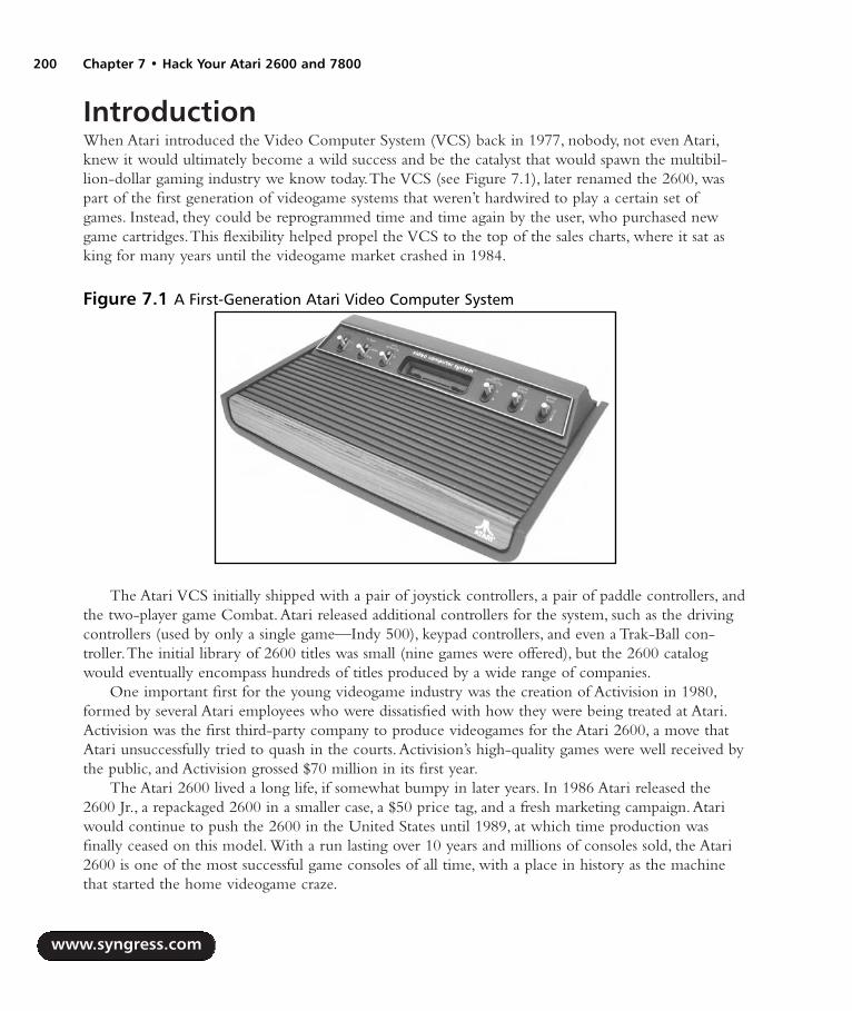
IntroductionWhen Atari introduced the Video Computer System (VCS) back in 1977, nobody, not even Atari,knew it would ultimately become a wild success and be the catalyst that would spawn the multibil-lion-dollar gaming industry we know today.The VCS (see Figure 7.1), later renamed the 2600, waspart of the first generation of videogame systems that weren’t hardwired to play a certain set ofgames. Instead, they could be reprogrammed time and time again by the user, who purchased newgame cartridges.This flexibility helped propel the VCS to the top of the sales charts, where it sat asking for many years until the videogame market crashed in 1984.
The Atari VCS initially shipped with a pair of joystick controllers, a pair of paddle controllers, andthe two-player game Combat.Atari released additional controllers for the system, such as the drivingcontrollers (used by only a single game—Indy 500), keypad controllers, and even a Trak-Ball con-troller.The initial library of 2600 titles was small (nine games were offered), but the 2600 catalogwould eventually encompass hundreds of titles produced by a wide range of companies.
One important first for the young videogame industry was the creation of Activision in 1980,formed by several Atari employees who were dissatisfied with how they were being treated at Atari.Activision was the first third-party company to produce videogames for the Atari 2600, a move thatAtari unsuccessfully tried to quash in the courts.Activision’s high-quality games were well received bythe public, and Activision grossed $70 million in its first year.
The Atari 2600 lived a long life, if somewhat bumpy in later years. In 1986 Atari released the2600 Jr., a repackaged 2600 in a smaller case, a $50 price tag, and a fresh marketing campaign.Atariwould continue to push the 2600 in the United States until 1989, at which time production wasfinally ceased on this model. With a run lasting over 10 years and millions of consoles sold, the Atari2600 is one of the most successful game consoles of all time, with a place in history as the machinethat started the home videogame craze.
www.syngress.com
200 Chapter 7 • Hack Your Atari 2600 and 7800
Figure 7.1 A First-Generation Atari Video Computer System
287_HRD_HACK_07.qxd 1/13/04 7:31 PM Page 200

Hack Your Atari 2600 and 7800 • Chapter 7 201
The Atari 7800 ProSystemUnder pressure from competitors that were eroding Atari’s market share by producing competingconsoles as well as clones of the 2600,Atari hastily released the Atari 5200 SuperSystem in 1982.TheAtari 5200 was a repackaged Atari 400 computer and did not represent development of a new gamesystem from scratch.That would not happen until the introduction of the Atari 7800 (see Figure 7.2)five years later.Atari’s original plans were to release the Atari 7800 in 1984, but those plans wereshelved when the company was purchased by the Tramiel family, who wanted to concentrate on thecomputer side of Atari’s business. If you’re looking for Atari 5200 hacks, the next chapter containsseveral for the 5200 as well as the related Atari 8-bit computers.
The 7800 was finally released in 1987 as a response to Nintendo’s successful NintendoEntertainment System (NES). Ironically, Nintendo had once approached Atari about selling the NESin the United States, but Atari spurned the offer. Had the 7800 been released in 1984 as originallyplanned, it likely would have done quite well. But the 7800 quickly succumbed to the NES jugger-naut and was unsuccessful at keeping the Atari name in the minds of videogame fans.
The Atari 7800 is more closely related to the 2600 than it is to the 5200, which is why we havegrouped the 2600 and 7800 systems together in this chapter. For starters, the Atari 7800 is backwardcompatible with 2600 games—the only system Atari would ever produce with built-in backwardcompatibility.The cartridges for the two systems are the same size, with the only discernable differ-ence being two additional “fingers” on the cartridge connector for 7800 games. Both systems feature9-pin controller ports, and 2600-compatible controllers work just fine with the 7800. In fact, 2600controllers can be used with 7800 games, except for those that require two independent fire buttons.The 7800 also uses the same hardware as the 2600 to produce sound, which unfortunately hinders the7800 in the audio department. One game, Ballblazer, actually contains a custom Atari “POKEY” chipinside the cartridge, which is the same sound chip built into the Atari 8-bit computers and the 5200.Thus, Ballblazer is the best-sounding game in the entire 7800 library.
www.syngress.com
Figure 7.2 The Atari 7800 ProSystem
287_HRD_HACK_07.qxd 1/13/04 7:31 PM Page 201

The 7800 suffered a fairly short lifespan, partly because of the fierce competition from Nintendoand the Sega Master System and partly because retailers were growing wary of Atari’s increasinginability to deliver on its promises. Only three games shipped at the system’s launch, with Atariannouncing many games that were never delivered.The system received poor distribution and weaksupport from third-party companies, with only three additional developers (Activision,AbsoluteEntertainment, and Froggo) producing games for the system.
Although the 7800 didn’t leave much of a mark on the videogame industry, it is a popular systemwith Atari fans. Nearly 60 games were released for the 7800, many of them quite enjoyable. It’s aneasy system to build up a complete collection of games for, since none of the 7800 titles is exceed-ingly rare.And because of the system’s backward compatibility with the 2600, you get the benefit ofusing one system to play both 7800 and 2600 games.
Hacks in This ChapterAlthough these systems are now over 20 years old, they have a large fan base keeping them alive andthriving in the 21st century.The classic gaming system with the most fans is easily the Atari 2600,with hundreds, if not thousands, of Web sites devoted to the game system that formed the basis of thevideogame industry today.A large community of programmers and hobbyists creates new games forthese systems, most notably the 2600, with access to resources the original programmers could onlydream of.Thanks to the Internet, fans of less popular and even very obscure systems can also gettogether to discuss their favorite games, share information, and most important, have fun!
Part of that fun is hacking these systems to do things they were never intended to do.The hacksin this chapter for the 2600 and 7800 only scratch the surface of what can be done. In this chapter,we cover how to:
Fix your 2600 joystick for left-handed gamers
Use an NES Control Pad with your 2600
Add stereo output to your 2600
Spice up your 7800 with a blue LED
Apply a 2600 compatibility fix to the 7800
Repair your 7800’s broken voltage regulator
Install a standard power jack in your 7800
If the hacks detailed here whet your appetite, we’ve put together a list of additional hacks thatyou can pursue by following the links at the end of this chapter. Let’s get started!
Atari 2600 Left-Handed Joystick ModificationThe Atari CX-40 joystick that shipped with the Atari 2600 is probably the single most recognizedcontroller in videogame history. However, in the late 1970s, ergonomic controller design was not aconcern of hardware designers, and in the case of the venerable CX-40, left-handed players were
www.syngress.com
202 Chapter 7 • Hack Your Atari 2600 and 7800
287_HRD_HACK_07.qxd 1/13/04 7:31 PM Page 202
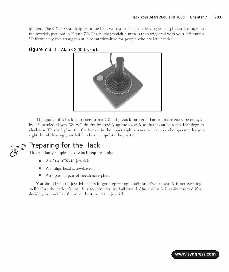
Hack Your Atari 2600 and 7800 • Chapter 7 203
ignored.The CX-40 was designed to be held with your left hand, leaving your right hand to operatethe joystick, pictured in Figure 7.3.The single joystick button is then triggered with your left thumb.Unfortunately, this arrangement is counterintuitive for people who are left-handed.
The goal of this hack is to transform a CX-40 joystick into one that can more easily be enjoyedby left-handed players. We will do this by modifying the joystick so that it can be rotated 90 degreesclockwise.This will place the fire button in the upper-right corner, where it can be operated by yourright thumb, leaving your left hand to manipulate the joystick.
Preparing for the HackThis is a fairly simple hack, which requires only:
An Atari CX-40 joystick
A Philips head screwdriver
An optional pair of needlenose pliers
You should select a joystick that is in good operating condition. If your joystick is not workingwell before the hack, it’s not likely to serve you well afterward.Also, this hack is easily reversed if youdecide you don’t like the rotated nature of the joystick.
www.syngress.com
Figure 7.3 The Atari CX-40 Joystick
287_HRD_HACK_07.qxd 1/13/04 7:31 PM Page 203

Performing the HackDo the following:
1. Flip the joystick over and use a Philips head screwdriver to remove the four screws, asshown in Figure 7.4.
2. With the joystick still upside down, carefully remove the base.There is a small spring beneaththe orange fire button—be careful not to lose it! Pull the top half of the joystick away; thispart will contain a clear plastic post (which gives the joystick its rigidity), the orange firebutton, and the spring inside the button (see Figure 7.5). Put these aside for now.
www.syngress.com
204 Chapter 7 • Hack Your Atari 2600 and 7800
Figure 7.4 Removing the Four Screws
Figure 7.5 Taking the Joystick Apart
287_HRD_HACK_07.qxd 1/13/04 7:31 PM Page 204

3. The joystick base contains a simple circuit board to which six wires are attached.Thesewires represent the four joystick directions, the fire button, and the ground. Pull the circuitboard out from the base to make it easier to work on. Using your fingers or a pair ofneedlenose pliers, swap the connectors according to Table 7.1 and as shown in Figure 7.6.
WARNING: HARDWARE HARM
When pulling the connectors out, make sure you are pulling by the metal and not on thewire! If you pull on the wire, you may separate the wire from the connector. If this happens,you will have to solder the wire back to the connector.
Table 7.1 Atari CX-40 Joystick Rewiring
Connector Original Connection Color New Color
1 Brown Blue2 White Brown3 Black Black4 Blue Green5 Green White6 Orange Orange
www.syngress.com
Hack Your Atari 2600 and 7800 • Chapter 7 205
Figure 7.6 Wire Swap
287_HRD_HACK_07.qxd 1/13/04 7:31 PM Page 205

4. After completing the wire swap, your board should resemble Figure 7.7.
5. After double-checking your work, you can reassemble the joystick.The easiest way to dothis is to hold the top half of the joystick upside down and then place the circuit board ontop of it, aligning the holes of the PCB with the plastic posts of the case.Take care to ensurethat the spring for the joystick button is properly sandwiched between the button and theboard, as shown in Figure 7.8.
6. Place the joystick base on top of the other half of the joystick, making sure that the wiresare bundled up along the side of the joystick and not underneath the circuit board.The twohalves of the joystick should fit together easily; if they do not, check to make sure that thewires are not encroaching on the board or between the two halves. Insert the four screwsinto the base of the joystick and tighten them with the Philips head screwdriver.
www.syngress.com
206 Chapter 7 • Hack Your Atari 2600 and 7800
Figure 7.7 Final Wire Positions
Figure 7.8 Joystick Button Spring
287_HRD_HACK_07.qxd 1/13/04 7:31 PM Page 206

www.syngress.com
Hack Your Atari 2600 and 7800 • Chapter 7 207
Now you can test out your creation! If you decide you don’t like the way the joystick feels, youcan easily reverse this hack by returning the wires to their original positions.
Use an NES Control Pad with Your 2600In 1986, two years after the videogame crash that decimated the industry, Nintendo released theNintendo Entertainment System (NES) in the United States.The NES helped breathe new life intothe videogame industry, and Nintendo sold over 62 million consoles before finally discontinuing theNES in 1995.
The NES shipped with a four-directional game pad (see Figure 7.9) featuring two fire buttons aswell as Select and Start buttons.These pads can easily be modified to work with the Atari 2600 andother systems that use 2600-compatible controllers (Atari 8-bit computers, Vic-20, Commodore 64,and so on).Thanks to the sheer volume of NES systems Nintendo sold over the years, finding NEScontrol pads to modify is not difficult at all.
Preparing for the HackThe only materials you’ll need for this hack are:
An Atari 2600 joystick (model number CX-40; see Figure 7.10)
A Nintendo control pad (model number NES-004)
Both are relatively easy to come by, through garage sales, flea markets, thrift stores, shops that sell usedgame consoles, and of course, eBay. Before performing this hack, you’ll want to test both controllers ifyou can. Specifically, make sure that the four directions and fire buttons work on each controllerbefore taking them apart.This will ensure that the cable from the Atari 2600 joystick is electricallysound and that the direction pad and buttons on the NES controller are without problems.
Figure 7.9 The NES Control Pad
287_HRD_HACK_07.qxd 1/13/04 7:31 PM Page 207

The tools required for this hack are as follows:
Phillips head screwdriver, jeweler’s size Used to open NES control pad
Phillips head screwdriver, standard size Used to open 2600 joystick
Wire cutters and strippers
Sharp razor blade or Dremel tool To cut circuit board traces
Soldering iron To solder cables to NES board
Solder sucker To remove parts from NES board
www.syngress.com
208 Chapter 7 • Hack Your Atari 2600 and 7800
Figure 7.10 The Atari 2600 CX-40 Joystick
287_HRD_HACK_07.qxd 1/13/04 7:31 PM Page 208

Performing the HackDo the following:
1. Use a jeweler’s Philips head screwdriver to remove the six screws from the bottom of theNES control pad, as shown in Figure 7.11.
2. Once you have removed the screws, lift up the back half of the control pad.You’ll see asimple circuit board, to which five wires and single IC are attached, as shown in Figure 7.12.
3. Remove the circuit board from the case, making sure to leave the rubber button mecha-nisms resting in the top half of the case. Unsolder the five wires as well as the chip from theboard. Be careful not to damage the solder pads for the chip on the opposite side of theboard, because this is where we’ll be attaching the wires from the Atari 2600 joystick cable.When you are finished, the board should resemble Figure 7.13.
www.syngress.com
Hack Your Atari 2600 and 7800 • Chapter 7 209
Figure 7.11 Bottom of NES Control Pad
Figure 7.12 Inside the NES Control Pad
287_HRD_HACK_07.qxd 1/13/04 7:31 PM Page 209
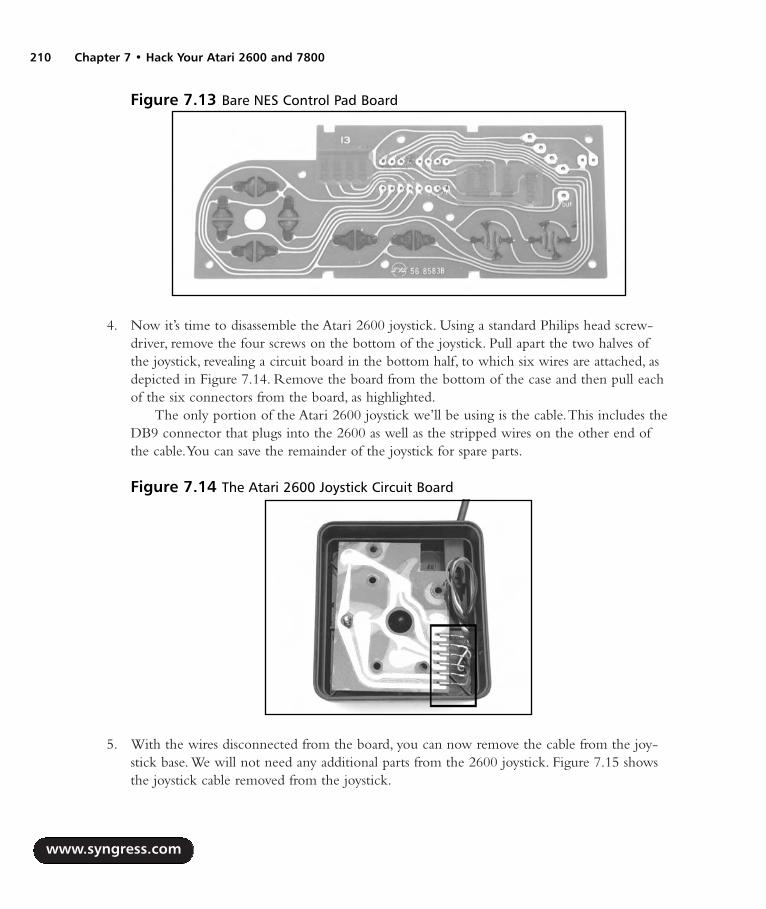
4. Now it’s time to disassemble the Atari 2600 joystick. Using a standard Philips head screw-driver, remove the four screws on the bottom of the joystick. Pull apart the two halves ofthe joystick, revealing a circuit board in the bottom half, to which six wires are attached, asdepicted in Figure 7.14. Remove the board from the bottom of the case and then pull eachof the six connectors from the board, as highlighted.
The only portion of the Atari 2600 joystick we’ll be using is the cable.This includes theDB9 connector that plugs into the 2600 as well as the stripped wires on the other end ofthe cable.You can save the remainder of the joystick for spare parts.
5. With the wires disconnected from the board, you can now remove the cable from the joy-stick base. We will not need any additional parts from the 2600 joystick. Figure 7.15 showsthe joystick cable removed from the joystick.
www.syngress.com
210 Chapter 7 • Hack Your Atari 2600 and 7800
Figure 7.13 Bare NES Control Pad Board
Figure 7.14 The Atari 2600 Joystick Circuit Board
287_HRD_HACK_07.qxd 1/13/04 7:31 PM Page 210

6. Using a pair of wire cutters, cut the metal connectors from the end of each wire. Now usewire strippers to remove a short length of insulation from each wire (see Figure 7.16).
7. Before we solder these wires to the NES board, we must first cut some traces on the board.With the traces of the circuit board facing you, we will number the pins 1–8 on the bottomrow where the IC was located. Using a sharp razor or Dremel tool, cut the trace immedi-ately above the solder pads for holes 2, 3, 4, and 5, as shown in Figure 7.17.
www.syngress.com
Hack Your Atari 2600 and 7800 • Chapter 7 211
Figure 7.15 Joystick Cable Removed
Figure 7.16 Prepped Wires
287_HRD_HACK_07.qxd 1/13/04 7:31 PM Page 211

WARNING: HARDWARE HARM
Make sure when cutting the traces that you do not damage the solder pads, because we willbe soldering the wires from the Atari 2600 to these pads. Also make sure you cut the tracesabove the pads and not below or you will render the circuit board unusable.
8. Now you need to cut one more trace.To the right of the holes for the IC are four verticalblack strips.You need to cut the trace immediately below the fourth black strip, as shown inFigure 7.18. Be careful to cut only the vertical trace, not the horizontal trace running belowthe row of black stripes.
www.syngress.com
212 Chapter 7 • Hack Your Atari 2600 and 7800
Figure 7.17 Cutting Traces
Figure 7.18 One More Trace to Cut
287_HRD_HACK_07.qxd 1/13/04 7:31 PM Page 212

9. Now it’s time to solder the Atari 2600 joystick cable to the NES control pad circuit board.The individual wires need to be soldered to the holes numbered in Figure 7.15, as describedin Table 7.2.You might want to tin the tip of each wire with solder before inserting themthrough the holes and soldering them into place.
Table 7.2 NES Control Pad Wiring
Hole Atari Joystick Wire Color
1 Black2 Brown3 Green4 Blue5 White8 Orange
10. When you’re finished, the wires should look as they do in Figure 7.19, as seen from theopposite side of the board.
11. Now place the board trace side down into the bottom half of the controller and thread thecable as shown in Figure 7.20. Be sure that the rubber cups for each button are sitting prop-erly in the bottom half of the controller. If you decided instead to cut the 2600 joystickcable before the stress relief connector, your wiring will look a bit different (and closer tothe original NES control pad cable).
www.syngress.com
Hack Your Atari 2600 and 7800 • Chapter 7 213
Figure 7.19 Wiring Complete
287_HRD_HACK_07.qxd 1/13/04 7:31 PM Page 213

12. Now place the back half of the NES control pad cover in place and affix the cover with thesix screws removed earlier (see Figure 7.21).You can test your new controller by plugging itinto an Atari 2600 (or another system that accepts 2600 controllers) and enjoying yourfavorite games!
Atari 2600 Stereo Audio OutputWhen Atari introduced the 2600, many home videogame consoles (which consisted mostly of Pongmachines at the time) had a built-in speaker for audio output. It appears that Atari was originallygoing to take this same route with the 2600, since the original six-switch model contains two recep-tacles for mounting small speakers inside the case. However, and thankfully,Atari decided to insteadsend the audio output to the television via the standard radio frequency (RF) output, so no Atari
www.syngress.com
214 Chapter 7 • Hack Your Atari 2600 and 7800
Figure 7.20 Reassembly of the Modified NES Control Pad
Figure 7.21 Hack Complete!
287_HRD_HACK_07.qxd 1/13/04 7:31 PM Page 214
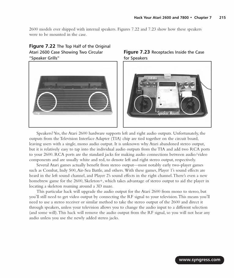
2600 models ever shipped with internal speakers. Figures 7.22 and 7.23 show how these speakerswere to be mounted in the case.
Speakers? Yes, the Atari 2600 hardware supports left and right audio outputs. Unfortunately, theoutputs from the Television Interface Adapter (TIA) chip are tied together on the circuit board,leaving users with a single, mono audio output. It is unknown why Atari abandoned stereo output,but it is relatively easy to tap into the individual audio outputs from the TIA and add two RCA portsto your 2600. RCA ports are the standard jacks for making audio connections between audio/videocomponents and are usually white and red, to denote left and right stereo output, respectively.
Several Atari games actually benefit from stereo output—most notably early two-player gamessuch as Combat, Indy 500,Air-Sea Battle, and others. With these games, Player 1’s sound effects areheard in the left sound channel, and Player 2’s sound effects in the right channel.There’s even a newhomebrew game for the 2600, Skeleton+, which takes advantage of stereo output to aid the player inlocating a skeleton roaming around a 3D maze.
This particular hack will upgrade the audio output for the Atari 2600 from mono to stereo, butyou’ll still need to get video output by connecting the RF signal to your television.This means you’llneed to use a stereo receiver or similar method to take the stereo output of the 2600 and direct itthrough speakers, unless your television allows you to change the audio input to a different selection(and some will).This hack will remove the audio output from the RF signal, so you will not hear anyaudio unless you use the newly added stereo jacks.
www.syngress.com
Hack Your Atari 2600 and 7800 • Chapter 7 215
Figure 7.22 The Top Half of the OriginalAtari 2600 Case Showing Two Circular“Speaker Grills”
Figure 7.23 Receptacles Inside the Casefor Speakers
287_HRD_HACK_07.qxd 1/13/04 7:31 PM Page 215

NOTE
If you’re up for more of a challenge, you can modify your 2600 to give it composite and/orS-video output as well as stereo audio output. This will result in a superior picture, but com-posite and S-video modifications can be tricky. A video hack for the 2600 is beyond thescope of this book, but you can examine the Atari 2600 FAQ (www.atariage.com/2600/faq)for more information.
Preparing for the HackThe first thing you’ll need is the Atari 2600 system that you want to modify. We will modify a four-switch Atari 2600, since these are the most common. Modifying other versions of the 2600 is similar,since they all use the same TIA chip. Most Atari 2600 consoles also use the same basic physicalhousing, except for the Atari 2600 Jr., which features a much smaller footprint.
Parts you’ll need for this hack are:
Two 2.0K 1-percent tolerance resistors
Two 0.1uF capacitors
Two RCA phono jacks
18”AWG wire
Tools required to perform this hack are as follows:
Phillips head screwdriver, standard size
Wire cutters and strippers
Needlenose pliers
Soldering iron
A drill or Dremel tool with a 1/4” drill bit
If you have a glue gun, you can use it to secure the audio cables to the 2600 board for a cleanerappearance (and to keep the cables out of harm’s way).
Performing the HackDo the following:
1. To begin, remove the screws from the bottom of the 2600 using a standard Philips screw-driver. Four screws secure the case together. Note that the two bottom screws are longer, soyou’ll want to be sure to insert these into the correct holes when you are reassembling theunit (see Figure 7.24).
www.syngress.com
216 Chapter 7 • Hack Your Atari 2600 and 7800
287_HRD_HACK_07.qxd 1/13/04 7:31 PM Page 216

2. Once you have removed the screws, pull the two halves of the case apart, unplug the RFcable from the board, and remove the circuit board from the case.Your system will nowresemble the illustration shown in Figure 7.25.
www.syngress.com
Hack Your Atari 2600 and 7800 • Chapter 7 217
Figure 7.24 The Underside of a Four-Switch Atari 2600
Figure 7.25 Atari 2600 Circuit Board with the RF Shield Attached
287_HRD_HACK_07.qxd 1/13/04 7:31 PM Page 217

3. Now you will need to remove the metal RF shield.To do this, use a pair of needlenose pliersto twist the small metal tabs along the edges of the RF shield so that the tabs line up with theholes in the shield.You should then be able to pull the two halves of the shield apart. Put theshield aside for now. Once the RF shield is removed, the board should resemble Figure 7.26.The TIA chip is at the bottom of the board, as highlighted in the picture.
4. If your TIA chip is socketed as shown in Figure 7.26, your job will be easier, since it is asimple matter to remove the chip and bend the two pins we’ll need to access. Otherwiseyou will need to carefully cut the two pins, which is somewhat more tricky. What we’reafter are pins 12 and 13, which represent the two audio channels of the 2600. If you look atthe opposite side of the board, you’ll see that these pins are tied together.An alternative tosoldering directly to the pins is to cut the trace between pins 12 and 13 on the opposite sideof the board and then solder to the connections on the bottom side of the board instead.However, there is less clearance with the RF shield on the bottom of the board, so caremust be taken to insulate any work performed on the backside of the board.
If the TIA chip is socketed, remove it and bend pins 12 and 13 upward, as shown inFigure 7.27.Then reinsert the chip into the socket, taking care to note the proper orienta-tion of the chip. If the chip is soldered to the board, you can use a Dremel tool to cut thepins as close to the board as possible and then bend them upward.
www.syngress.com
218 Chapter 7 • Hack Your Atari 2600 and 7800
Figure 7.26 Atari 2600 Circuit Board with RF Shield Removed
287_HRD_HACK_07.qxd 1/13/04 7:31 PM Page 218

5. Now warm up your soldering iron and solder the two 2.0K ohm resistors from pins 12 and13 to the 5V solder pad shown in Figure 7.28.
6. Now prepare the two wires that you will be soldering to the audio jacks on the back of the2600 case. Cut two lengths of 18-gauge wire, each about a foot long.These wires will runfrom the TIA chip to the back of the case. Solder a 0.1uF capacitor to each of these cables.You might want to cut a 1-inch or so length of 1/32-inch heat-shrink tubing and slide itover each of these cables—these will help shield the connections you make to the TIA chip.If you don’t have heat-shrink tubing, you can also use electrical tape to insulate the connec-tions, but it’s important that they are shielded in some fashion to prevent shorts from occur-ring when the RF shield is replaced. Now take the opposite end of each capacitor andsolder one each to the joints formed by pins 12 and 13 and the two resistors you previouslysoldered, as shown in Figure 7.29.
www.syngress.com
Hack Your Atari 2600 and 7800 • Chapter 7 219
Figure 7.27 TIA Chip with Pins 12 and 13 Bent Upward
Figure 7.28 Resistors Soldered to the TIA
287_HRD_HACK_07.qxd 1/13/04 7:31 PM Page 219

7. We now have to prepare the 2600 case to mount the two RCA jacks.The easiest place tomount the jacks is along the back side of the top half of the case.This is the same side thatthe RF cable resides on. Using a drill or Dremel tool with a 1/4” drill bit, drill the twoholes (see Figure 7.30).
WARNING: HARDWARE HARM
Do not place the holes too close to the side of the case, or too low, or they will be difficultto access from either inside the case or the outside (when the top half of the 2600 case sitson the bottom half, there is a lip that overlaps). Also, space the holes sufficiently wide apartso that the two jacks are not too close to one another.
www.syngress.com
220 Chapter 7 • Hack Your Atari 2600 and 7800
Figure 7.29 Capacitors Soldered to the TIA
Figure 7.30 Cutting Holes in the 2600 Case
287_HRD_HACK_07.qxd 1/13/04 7:31 PM Page 220

8. Once the holes are drilled, you can attach the two RCA jacks.They should comprise threepieces: the jack itself, a small washer, and a nut. For each jack, remove the washer and nut,and push the threaded side of the jack through from the outside of the case.Then slide thewasher over the jack and screw the nut into place. When attached, they should resembleFigure 7.31.
9. With the jacks attached, you can now solder the last few connections.The tab on the out-side ring of each jack needs to be soldered to ground. Join these two tabs together with apiece of wire (preferably black so it is easy to denote as a ground connection), and thenusing a longer length of wire, solder one of the tabs to an available ground on the circuitboard. If you flip the board over, you’ll see that the most convenient solder point is con-nected to the Channel 3/4 switch. Solder the wire to this location, as shown in Figure 7.32.
10. The only two remaining connections are for the wires you soldered to the TIA chip. Solderone wire each to the center post of each RCA jack, as shown in Figure 7.33.
www.syngress.com
Hack Your Atari 2600 and 7800 • Chapter 7 221
Figure 7.31 RCA Jacks Attached
Figure 7.32 Solder RCA Phono Jacks to Ground
287_HRD_HACK_07.qxd 1/13/04 7:31 PM Page 221

11. You’re done! Your completed hack should look similar to Figure 7.34.You can use a gluegun to securely attach the wires to the circuit board, to make sure that they don’t get in theway of the cartridge port or switches.
Reassemble the 2600 by replacing the RF shield, plugging the RF cable into the board, placingthe board back in the case, and screwing the case back together. (Remember, the long screws are forthe bottom holes.) Once the device is assembled (see Figure 7.35), hook your 2600 up to your televi-sion and stereo system and fire up a game of Combat.You should distinctly hear Player 1’s tank in onespeaker and Player 2’s tank in the other.Try some other games as well—you might be surprised at thestereo effects you find!
If you’d like to try your hand at Skeleton+, a modern homebrew game programmed to takeadvantage of stereo output, you can purchase the game in cartridge form at AtariAge(www.atariage.com/store).You can also download the binary from AtariAge so that you can try it inyour favorite Atari 2600 emulator before buying—the author has made it freely available for anyoneto download.
www.syngress.com
222 Chapter 7 • Hack Your Atari 2600 and 7800
Figure 7.33 Solder Wires from TIA to Center Posts of RCA Jacks
Figure 7.34 Completed Stereo Hack
287_HRD_HACK_07.qxd 1/13/04 7:31 PM Page 222

Under the Hood: How the Hack WorksThe specialized TIA chip in the Atari 2600 supports two audio channels, which are output separatelyon different pins exiting the chip.As soon as these pins connect to the circuit board, they are tiedtogether, resulting in a monaural output from your television. Because the signals for these two chan-nels exit the TIA separately, we can tap into them and direct the signals elsewhere, as we have donewith this hack.
Many games are stereo in nature, due only to the fact that the Atari 2600 has two audio channels.Many of Atari’s earlier games used one channel for Player 1’s sound effects and the second channel forPlayer 2’s sound effects.This results in a very noticeable and useful stereo effect.A recent homebrewgame for the 2600, Skeleton+, intentionally uses the stereo effect to help direct the player to his foein a 3D maze. However, with some games, the stereo effect might be less desirable, as is the case withPitfall II, where the (excellent) music plays in one channel and the sound effects in the other.
A useful addition to this hack is to add a switch that allows you to toggle between stereo outputand mono output.This would allow you to enjoy games like Pitfall II, without having to deal withpotentially annoying stereo sound effects.
Atari 7800 Blue LED ModificationThe Atari 7800 features a red LED that is illuminated when the system power is on.This hackexplains how you can replace this stock LED with a blue LED to add a unique touch to your Atari7800 system.
Preparing for the HackFor this hack you’ll need two components (shown in Figure 7.36):
Α 3.7V, 20mA, 2600mcd blue LED, Radio Shack part #276-316
Α 470 ohm, 1/4 watt, 5-percent resistor, Radio Shack part #271-1317
www.syngress.com
Hack Your Atari 2600 and 7800 • Chapter 7 223
Figure 7.35 Stereo Jacks on Outside of Case
287_HRD_HACK_07.qxd 1/13/04 7:31 PM Page 223
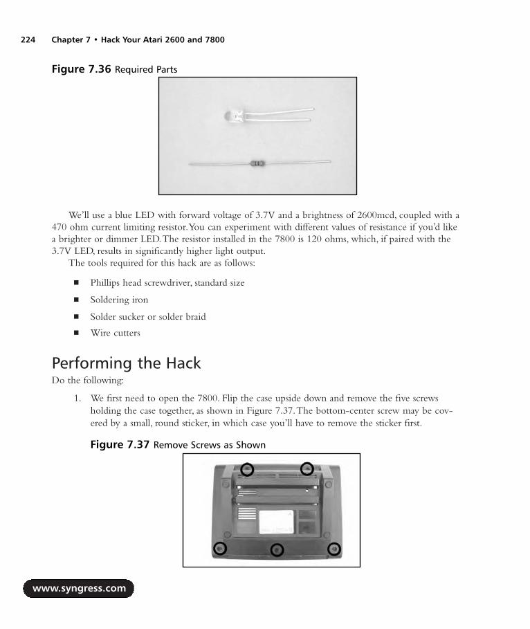
We’ll use a blue LED with forward voltage of 3.7V and a brightness of 2600mcd, coupled with a470 ohm current limiting resistor.You can experiment with different values of resistance if you’d likea brighter or dimmer LED.The resistor installed in the 7800 is 120 ohms, which, if paired with the3.7V LED, results in significantly higher light output.
The tools required for this hack are as follows:
Phillips head screwdriver, standard size
Soldering iron
Solder sucker or solder braid
Wire cutters
Performing the HackDo the following:
1. We first need to open the 7800. Flip the case upside down and remove the five screwsholding the case together, as shown in Figure 7.37.The bottom-center screw may be cov-ered by a small, round sticker, in which case you’ll have to remove the sticker first.
www.syngress.com
224 Chapter 7 • Hack Your Atari 2600 and 7800
Figure 7.36 Required Parts
Figure 7.37 Remove Screws as Shown
287_HRD_HACK_07.qxd 1/13/04 7:31 PM Page 224

2. Turn the case back over and then remove the top half of the case.The board will be sittinginside; remove it from the case. It is not necessary to remove the RF shield from the boardto perform this hack, but we removed it to make the board easier to work on.To removethe RF shield, use a pair of needlenose pliers to straighten all the metal tabs holding theshield in place, and simply pull the shield up off the board, as shown in Figure 7.38.
3. We’re going to be working with the lower-left portion of the Atari 7800 circuit boardwhere the LED is located, as highlighted in Figure 7.39.
4. The next order of business is to remove the existing LED and the accompanying resistor, ashighlighted in Figure 7.39. Flip the board over and unsolder the four connections shown inFigure 7.40.To remove the LED from the board, you will need to squeeze the two plastictabs holding the plastic housing for the LED to the board.
www.syngress.com
Hack Your Atari 2600 and 7800 • Chapter 7 225
Figure 7.38 Remove RF Shielding
Figure 7.39 The Atari 7800 LED
287_HRD_HACK_07.qxd 1/13/04 7:31 PM Page 225

WARNING: HARDWARE HARM
Be careful when removing the LED from the board—you don’t want to pull up the solderpads from the front side of the board, to which you don’t have access due to the LED’splastic spacer. Try to remove as much solder as possible from the joints on the bottom of theboard, and then carefully pull the LED up from the board while heating the connections.
5. Once you have unsoldered the resistor and LED, remove the red LED from the white plasticspacer. Place the blue LED into the spacer and then solder it to the board.The long lead ofthe LED is positive and must be soldered to the connection closest to the resistor youremoved.The positive lead is highlighted on the back of the board in Figure 7.40. Next,solder the 470 ohm resistor in the space formally occupied by the original resistor youremoved. When you’re done, the LED and resistor should resemble Figure 7.41.
www.syngress.com
226 Chapter 7 • Hack Your Atari 2600 and 7800
Figure 7.40 Unsolder and Remove
Figure 7.41 New LED and Resistor
287_HRD_HACK_07.qxd 1/13/04 7:31 PM Page 226

6. If you are careful and don’t have anything underneath the 7800 that could short any con-nections on the bottom side of the board, you can plug in the power supply and press thepower button (lower-left corner, as denoted in Figure 7.42) to see how the new LED looks.However, for a more accurate gauge of how the LED looks, you should view the LEDinside the assembled case, since the hole for the LED on the 7800 is fairly small.
7. You can now reassemble your 7800 by placing the board back in the bottom half of the case,fitting the top half of the case back in place, and then screwing the case back together usingthe five screws you removed earlier (see Figure 7.43). Enjoy the new look of your Atari 7800!
Under the Hood: How the Hack WorksSo how did we decide to use a 470 ohm resistor and an LED with a forward voltage of 3.7 volts? Weuse Ohm’s Law, which allows us to calculate a reasonable value for the resistor based on what weknow about the available voltage and the specifications of the LED. In this case, we have 5 volts avail-able as supplied to us by the 7800.The existing resistor in the 7800 is 150 ohms.The specifications ofthe blue LED we’d like to use are:
www.syngress.com
Hack Your Atari 2600 and 7800 • Chapter 7 227
Figure 7.42 Power Applied
Figure 7.43 Blue LED Happiness on the Atari 7800
287_HRD_HACK_07.qxd 1/13/04 7:32 PM Page 227

Forward voltage (VF): 3.7V
Forward current (IF): 20mA
The resistor is placed in series with the LED to act as a current limiter and to let only the desiredcurrent pass to the LED.This is done to protect the LED from exceeding its maximum current speci-fication. By adjusting the value of the resistor, we adjust the amount of current going to the LED,which in turn changes the brightness of LED illumination.Armed with this information, we can cal-culate our desired resistor value using Ohm’s Law, which states:
Voltage = Current x Resistance, or V = I x R
To calculate resistance, we use the formula as follows:
Resistance = Voltage / Current, or R = V / I
Plugging in the values for the voltage and current expected by the LED, we get:
R = (5V – 3.7V) / 0.02A = 65 ohm
So, in this case, if we were to use a 65 ohm resistor, this would power the LED at its 20mA for-ward current (essentially the full brightness of the LED), and given the LED’s high efficiency(2600mcd), it would be very bright indeed. We want to see the LED, but we don’t want it so brightthat our eyes are drawn to it while we’re trying to focus on the games we’re playing.Therefore, wewant more resistance before the LED, which will limit more current going to the LED and cause theLED to be dimmer in appearance.
With an application such as this, you often need to experiment to find a brightness that is appro-priate.Applying Ohm’s Law allows us to determine the minimum resistance required so we don’toverpower the LED, which could cause it to burn out.A 470 ohm value seems to result in a reason-able level of brightness that is easily visible when the 7800 case is put back together, but not over-bearing.Again using Ohm’s Law, we can determine how much current this results going to the LED:
Current = Voltage / Resistance, or I = V / R
I = (5V – 3.7V) / 470 ohms = 0.0027A = 2.7mA
Using this formula, we can see that we are driving the LED at 2.7mA, which is only a fraction ofthe current the LED is rated at, significantly reducing its brightness. Feel free to experiment with dif-ferent values of resistance to increase or decrease the LED’s light output.
Atari 7800 Game Compatibility Hack to Play Certain 2600 GamesThe Atari 7800,Atari’s third-generation cartridge-based game console, will play Atari 2600 gameswithout needing an additional adapter, unlike Atari’s second-generation system, the 5200, whichrequires the VCS Cartridge Adapter to play 2600 games. However, some cartridges will not work onmany 7800 consoles, including Activision games that use the FE bank-switching method (Space
www.syngress.com
228 Chapter 7 • Hack Your Atari 2600 and 7800
287_HRD_HACK_07.qxd 1/13/04 7:32 PM Page 228

Shuttle, Robot Tank, and Decathlon), as well as the Supercharger and Cuttle Cart, two RAM-baseddevices that allow games to be loaded into their memory.
Atari added a circuit to later versions of the Atari 7800 to fix a compatibility problem with the2600 game Dark Chambers but in the process broke compatibility with other previously mentionedtitles.This hack will show you how to modify your 7800 to fix the compatibility problems and letyou play more 2600 games. However, executing the hack will prevent the 2600 version of DarkChambers from playing (though the 7800 version will still work fine).
NEED TO KNOW… WHAT IS BANK SWITCHING?When Atari designed the 2600, they gave it a 12-bit-wide external address space and an 8-bit-wide data bus, limiting 2600 games to a maximum size of 4KB without any special cir-cuitry. At the time the 2600 was designed, Atari’s hardware engineers felt that 4K would bemore than enough for any 2600 game.
To get around the cartridge size limitation, Atari introduced bank switching with therelease of the game Asteroids. Bank switching is a method used to overcome a memory sizelimitation (such as 4KB for the Atari 2600) and allows a larger-size memory device to be usedwith a cartridge, thus providing more data storage for the system. Bank switching requiresspecially designed logic circuitry on the cartridge to handle the specific schemes. In the caseof Asteroids, Atari used what is now known as the F8 bank-switching scheme (for 8K),although they would later create games that use F6 (for 16K games) and F4 (for 32K games).Third-party companies such as Activision would develop their own bank-switching schemesindependently, leading to a wide variety of bank-switching methods, including the FEmethod Activision uses that causes problems on many Atari 7800 consoles.
Bank switching generally works by defining “hot spots” the game program uses toswitch between memory sections (or banks) of the game ROM. In the case of Atari’s F8method, this is used to switch between two 4K banks of memory. Having two 4KB banksgives the system a possible 8KB of accessible data space. If the game accesses address 1FF8,the first 4KB bank is used. If the game accesses address 1FF9, the second 4KB bank is used.This is the simplest bank-switching method and the most commonly implemented.
For a thorough explanation of the majority of known bank-switching methods, refer towww.tripoint.org/kevtris/files/sizes.txt, written by Kevin Horton.
Preparing for the HackThis is a quick and easy hack.The required tools as follows:
Phillips head screwdriver, standard size
Wire cutters and stripper
Needlenose pliers
Soldering iron (optional) if you want to remove the component instead of just clipping it out
www.syngress.com
Hack Your Atari 2600 and 7800 • Chapter 7 229
287_HRD_HACK_07.qxd 1/13/04 7:32 PM Page 229

Solder sucker or solder braid (optional) if you want to remove the component instead ofjust clipping it out
Performing the HackDo the following:
1. The first thing we need to do is open the 7800. Flip the case upside down and remove thefive screws holding the case together.The bottom-center screw might be covered by a smallsticker.A picture of the bottom of the 7800 case with the screw locations highlighted can befound in Figure 7.37 earlier in this chapter. Remove the top of the case, and then extract theboard from the case. Using a pair of needlenose pliers, straighten all the metal tabs holding theRF shielding in place, as shown in Figure 7.44. Don’t forget the two that are between the topof the cartridge port and the metal heat sink at the top of the board.
2. Once you have the RF shield removed, you need to verify that this compatibility fix appliesto your particular 7800.The area we are interested in is depicted in Figure 7.45.
www.syngress.com
230 Chapter 7 • Hack Your Atari 2600 and 7800
Figure 7.44 Removing the RF Shield
Figure 7.45 Atari 7800 Board
287_HRD_HACK_07.qxd 1/13/04 7:32 PM Page 230
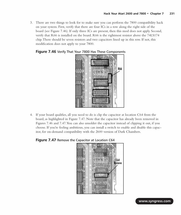
3. There are two things to look for to make sure you can perform the 7800 compatibility hackon your system. First, verify that there are four ICs in a row along the right side of theboard (see Figure 7.46). If only three ICs are present, then this mod does not apply. Second,verify that R66 is installed on the board. R66 is the rightmost resistor above the 74LS174chip.There should be seven resistors and two capacitors lined up in this row. If not, thismodification does not apply to your 7800.
4. If your board qualifies, all you need to do is clip the capacitor at location C64 from theboard, as highlighted in Figure 7.47. Note that the capacitor has already been removed inFigures 7.46 and 7.47.You can also unsolder the capacitor instead of clipping it out, if youchoose. If you’re feeling ambitious, you can install a switch to enable and disable this capac-itor, for on-demand compatibility with the 2600 version of Dark Chambers.
www.syngress.com
Hack Your Atari 2600 and 7800 • Chapter 7 231
Figure 7.46 Verify That Your 7800 Has These Components
Figure 7.47 Remove the Capacitor at Location C64
287_HRD_HACK_07.qxd 1/13/04 7:32 PM Page 231

5. Now you can reassemble your 7800. First, replace the RF shield, making sure you retwistthe metal tabs that keep the two halves of the RF shield together.Then place the board inthe bottom half of the 7800 shell, attach the top half of the case, and screw the case backtogether with the five screws you removed earlier.
You can now test some of the games known to have problems with the Atari 7800, includingActivison’s Decathlon, Robot Tank, and Space Shuttle. In addition, the Supercharger and Cuttle Cartcartridges should also work without problems.
Under the Hood: How the Hack WorksThis hack works by disabling a circuit that Atari apparently installed in order to fix a compatibilityissue with Atari’s 2600 version of Dark Chambers.This timing circuit involves the 74LS02 (a Quad 2-Input NOR gate), the logic chip directly below the C64 capacitor you clipped or removed. SomeAtari 7800 systems are missing this chip as well as C64 and R66. Figure 7.48 highlights a 7800 boardthat never had these parts installed.
Atari 7800 Voltage Regulator ReplacementA common problem for the Atari 7800 is for the 5V voltage regulator to fail.This will render your7800 inoperable because the system will not receive power. It’s even possible for the regulator tocompletely snap off the board due to the weight of the attached heat sink. On many 7800s the heatsink is not soldered into place, allowing it to wobble back and forth, which causes stress and wear onthe pins.This simple hack simply involves opening the 7800, removing the existing voltage regulator,and soldering a new one in place.
www.syngress.com
232 Chapter 7 • Hack Your Atari 2600 and 7800
Figure 7.48 A 7800 Board Without the Compatibility Circuit
287_HRD_HACK_07.qxd 1/13/04 7:32 PM Page 232
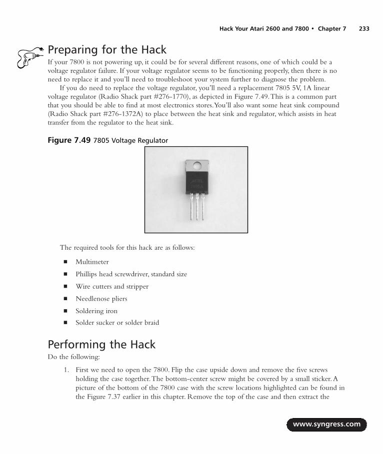
Preparing for the HackIf your 7800 is not powering up, it could be for several different reasons, one of which could be avoltage regulator failure. If your voltage regulator seems to be functioning properly, then there is noneed to replace it and you’ll need to troubleshoot your system further to diagnose the problem.
If you do need to replace the voltage regulator, you’ll need a replacement 7805 5V, 1A linearvoltage regulator (Radio Shack part #276-1770), as depicted in Figure 7.49.This is a common partthat you should be able to find at most electronics stores.You’ll also want some heat sink compound(Radio Shack part #276-1372A) to place between the heat sink and regulator, which assists in heattransfer from the regulator to the heat sink.
The required tools for this hack are as follows:
Multimeter
Phillips head screwdriver, standard size
Wire cutters and stripper
Needlenose pliers
Soldering iron
Solder sucker or solder braid
Performing the HackDo the following:
1. First we need to open the 7800. Flip the case upside down and remove the five screwsholding the case together.The bottom-center screw might be covered by a small sticker.Apicture of the bottom of the 7800 case with the screw locations highlighted can be found inthe Figure 7.37 earlier in this chapter. Remove the top of the case and then extract the
www.syngress.com
Hack Your Atari 2600 and 7800 • Chapter 7 233
Figure 7.49 7805 Voltage Regulator
287_HRD_HACK_07.qxd 1/13/04 7:32 PM Page 233

board. Using a pair of needlenose pliers, straighten all the metal tabs holding the RFshielding in place. Don’t forget the two that are between the top of the cartridge port andthe metal heat sink at the top of the board.The voltage regulator is located at the top of theboard, immediately above the cartridge port, as shown in Figure 7.50.
2. You’ll first want to test the voltage regulator to see if power is even reaching it and thencheck to see what the output voltage is.To do this, plug the 7800 power supply into theboard, and then apply power to the system by pressing the power button located in thelower-left corner of the board.Then carefully flip the board over and use a multimeter tomeasure the voltage on the input and output pins of the regulator. Figure 7.51 highlightsthe relevant pins on the reverse side of the 7800 board.You should measure approximately12V on the input side and 5V on the output. If you do not measure a voltage on the inputto the regulator, the regulator might be loose or broken on the board (or your problem lieselsewhere). If you measure a voltage on the input side but do not measure a voltage on theoutput side (or if your output voltage is not hovering around 5V), this hack is for you!
www.syngress.com
234 Chapter 7 • Hack Your Atari 2600 and 7800
Figure 7.50 Atari 7800 Voltage Regulator and Heat Sink
Figure 7.51 Voltage Regulator Connections
287_HRD_HACK_07.qxd 1/13/04 7:32 PM Page 234

3. To continue with the hack, turn the power off to the 7800 and unplug the power adapterfrom the board.To remove the voltage regulator, unsolder the three connections for thevoltage regulator on the backside of the board. If the heat sink is also soldered in place,unsolder that from the board as well. Figure 7.52 shows which connections you want tounsolder.
4. Flip the board back over so that the component side is visible, and lift the voltage regulatorand heat sink as one piece from the board. Unscrew the voltage regulator from the heatsink. Discard the regulator but keep the screw, nut, and washer.Apply a small amount ofthermal transfer compound to the backside of the new voltage regulator.Attach the newregulator to the heat sink using the screw, nut, and washer you saved, as shown in Figure7.53.The washer and nut should be used on the side of the heat sink opposite the voltageregulator.
5. Carefully place the leads for the voltage regulator through the three holes in the circuitboard, as well as the mounts for the heat sink through the larger holes intended for them.Flip the board over and solder the voltage regulator in place.You should also solder the heatsink in place so it is more secure, but you will need to use a higher-temperature soldering
www.syngress.com
Hack Your Atari 2600 and 7800 • Chapter 7 235
Figure 7.52 Unsolder the Heat Sink and Voltage Regulator
Figure 7.53 New Voltage Regulator Attached to Heat Sink
287_HRD_HACK_07.qxd 1/13/04 7:32 PM Page 235
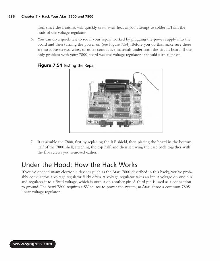
iron, since the heatsink will quickly draw away heat as you attempt to solder it.Trim theleads of the voltage regulator.
6. You can do a quick test to see if your repair worked by plugging the power supply into theboard and then turning the power on (see Figure 7.54). Before you do this, make sure thereare no loose screws, wires, or other conductive materials underneath the circuit board. If theonly problem with your 7800 board was the voltage regulator, it should turn right on!
7. Reassemble the 7800, first by replacing the RF shield, then placing the board in the bottomhalf of the 7800 shell, attaching the top half, and then screwing the case back together withthe five screws you removed earlier.
Under the Hood: How the Hack WorksIf you’ve opened many electronic devices (such as the Atari 7800 described in this hack), you’ve prob-ably come across a voltage regulator fairly often.A voltage regulator takes an input voltage on one pinand regulates it to a fixed voltage, which is output on another pin.A third pin is used as a connectionto ground.The Atari 7800 requires a 5V source to power the system, so Atari chose a common 7805linear voltage regulator.
www.syngress.com
236 Chapter 7 • Hack Your Atari 2600 and 7800
Figure 7.54 Testing the Repair
287_HRD_HACK_07.qxd 1/13/04 7:32 PM Page 236
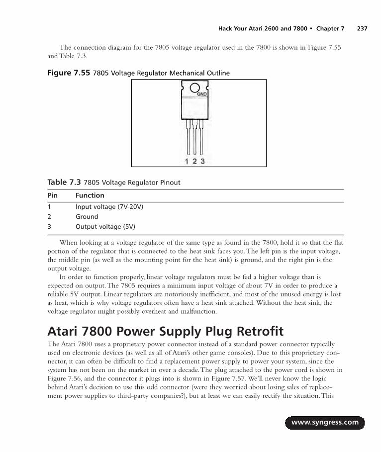
The connection diagram for the 7805 voltage regulator used in the 7800 is shown in Figure 7.55and Table 7.3.
Table 7.3 7805 Voltage Regulator Pinout
Pin Function
1 Input voltage (7V-20V)2 Ground3 Output voltage (5V)
When looking at a voltage regulator of the same type as found in the 7800, hold it so that the flatportion of the regulator that is connected to the heat sink faces you.The left pin is the input voltage,the middle pin (as well as the mounting point for the heat sink) is ground, and the right pin is theoutput voltage.
In order to function properly, linear voltage regulators must be fed a higher voltage than isexpected on output.The 7805 requires a minimum input voltage of about 7V in order to produce areliable 5V output. Linear regulators are notoriously inefficient, and most of the unused energy is lostas heat, which is why voltage regulators often have a heat sink attached. Without the heat sink, thevoltage regulator might possibly overheat and malfunction.
Atari 7800 Power Supply Plug RetrofitThe Atari 7800 uses a proprietary power connector instead of a standard power connector typicallyused on electronic devices (as well as all of Atari’s other game consoles). Due to this proprietary con-nector, it can often be difficult to find a replacement power supply to power your system, since thesystem has not been on the market in over a decade.The plug attached to the power cord is shown inFigure 7.56, and the connector it plugs into is shown in Figure 7.57. We’ll never know the logicbehind Atari’s decision to use this odd connector (were they worried about losing sales of replace-ment power supplies to third-party companies?), but at least we can easily rectify the situation.This
www.syngress.com
Hack Your Atari 2600 and 7800 • Chapter 7 237
Figure 7.55 7805 Voltage Regulator Mechanical Outline
287_HRD_HACK_07.qxd 1/13/04 7:32 PM Page 237

hack will show you how to add a standard power jack to your Atari 7800 so you can use an off-the-shelf power adapter. We’ll leave the existing 7800 power jack in place so you can continue to use it ifyou choose.
Preparing for the HackFor this hack you’ll need:
A panel-mount 1/8-inch phone jack, Radio Shack part #274-248
Two lengths of 18AWG insulated copper wire to connect the phone jack to the 7800 powerconnections, each about a foot long, preferably red and black
You’ll also want a 5V, 1A power supply with a 1/8-inch connector, center positive, to use withyour new power jack once it’s assembled.You can also use a 2600 power supply, which is morecommon though only supplies 500mA of power.This is sufficient to power the 7800, but some car-tridges, such as the Cuttle Cart, may not operate properly with the 2600 adapter.The tools requiredfor this hack are as follows:
Phillips head screwdriver, standard size
Wire cutters and stripper
Soldering iron
Small adjustable wrench or needlenose pliers
Heat gun
Drill or Dremel tool
www.syngress.com
238 Chapter 7 • Hack Your Atari 2600 and 7800
Figure 7.56 Atari 7800 Power Connector Figure 7.57 Atari 7800 Power Receptacle
287_HRD_HACK_07.qxd 1/13/04 7:32 PM Page 238

Performing the HackDo the following:
1. The first thing we need to do is to open the 7800. Flip the case upside down and removethe five screws holding the case together.The bottom-center screw might be covered by asmall sticker.A picture of the bottom of the 7800 case with the screw locations highlightedcan be found in Figure 7.37 in this chapter. Remove the top of the case.The board will besitting inside; remove it from the case. Using a pair of needlenose pliers, straighten all themetal tabs holding the RF shielding in place. Don’t forget the two that are between the topof the cartridge port and the metal heat sink at the top of the board. Once the RF shieldingis removed, the 7800 circuit board should resemble Figure 7.58.
2. The existing power supply connector is on the upper-right corner of the board, adjacent toa large capacitor, as shown in Figure 7.59. We’ll be leaving the existing connector in place,but an alternative to this hack is to remove the existing power connector and place a newconnector directly on the board. We’ll mount the new connector in the bottom shell of thecase, about a half-inch down from the top edge of the shell.
www.syngress.com
Hack Your Atari 2600 and 7800 • Chapter 7 239
Figure 7.58 Atari 7800 Circuit Board
Figure 7.59 Existing Power Connector
287_HRD_HACK_07.qxd 1/13/04 7:32 PM Page 239

3. Remove the nut and washer from the1/8-inch phono jack.These will be usedto secure the jack to the case, so putthem aside for now. Cut two 4-inchlengths of the 18AWG wire.You can uselonger lengths of wire to give you moreflexibility.These wires will connectpower and ground from the 7800 boardto the phono jack. If you can, use blackwire for the ground connection and redwire for the positive connection, asshown in Figure 7.60. Strip a short pieceof insulation from the ends of each wire.
4. Solder one wire to the center post of the phono jack (which will be positive) and the otherto the ground terminal.There may be more than two terminals, so if you’re unsure what’spositive and negative, use a continuity tester to verify that you are attaching the wires to thecorrect locations.
5. Now it’s time to solder these connections to the 7800 board. It’s easiest to solder these con-nections to the backside of the board, so that’s what we’ll do here. Flip the board over andlocate the corner where the existing power connector is attached. We will solder to the twolarge solder pads directly to the right of the connector (as shown in Figure 7.61). Solder thepositive wire to the right solder pad, and the ground wire to the left solder pad.
WARNING: HARDWARE HARM
Ensure that the wires are connected to the proper locations on the phono jack and the 7800circuit board. Failure to do so may cause damage to your 7800, power supply, or circuitbreakers in your home when you apply power.
www.syngress.com
240 Chapter 7 • Hack Your Atari 2600 and 7800
Figure 7.60 Wired Phono Jack
Figure 7.61 Solder Wires to Board
287_HRD_HACK_07.qxd 1/13/04 7:32 PM Page 240
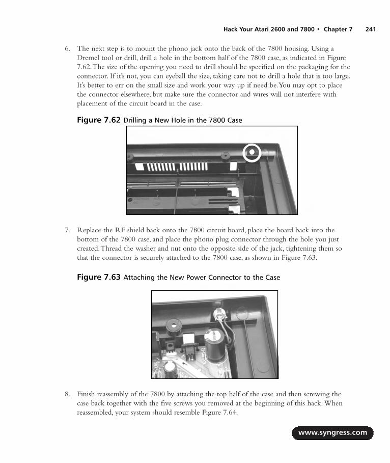
6. The next step is to mount the phono jack onto the back of the 7800 housing. Using aDremel tool or drill, drill a hole in the bottom half of the 7800 case, as indicated in Figure7.62.The size of the opening you need to drill should be specified on the packaging for theconnector. If it’s not, you can eyeball the size, taking care not to drill a hole that is too large.It’s better to err on the small size and work your way up if need be.You may opt to placethe connector elsewhere, but make sure the connector and wires will not interfere withplacement of the circuit board in the case.
7. Replace the RF shield back onto the 7800 circuit board, place the board back into thebottom of the 7800 case, and place the phono plug connector through the hole you justcreated.Thread the washer and nut onto the opposite side of the jack, tightening them sothat the connector is securely attached to the 7800 case, as shown in Figure 7.63.
8. Finish reassembly of the 7800 by attaching the top half of the case and then screwing thecase back together with the five screws you removed at the beginning of this hack. Whenreassembled, your system should resemble Figure 7.64.
www.syngress.com
Hack Your Atari 2600 and 7800 • Chapter 7 241
Figure 7.62 Drilling a New Hole in the 7800 Case
Figure 7.63 Attaching the New Power Connector to the Case
287_HRD_HACK_07.qxd 1/13/04 7:32 PM Page 241

Now it’s time to test your work! Hook the 7800 to a video source, insert a 2600 or 7800 game, andplug in an appropriate power supply to the new jack you just added.Turn the system on, and enjoy!
Other HacksThe hacks presented in this chapter are only the beginning of what you can do with your old gamingsystems. We’ve listed some of the more complex and advanced hacks here; detailed instructions formany of these are available on the Internet. Whenever possible we’ve pointed you toward resourcesfor additional information.
2600 Composite/S-Video ModificationsThe quality of the standard RF output on an Atari 2600 can be lacking, especially if you’re using aTV/Game switchbox that further reduces the videosignal.The first and easiest thing you can do toimprove your video signal is to replace the TV/Gameswitchbox with a coaxial (F-Type) to Female RCAadapter, which you can find at Radio Shack (part#278-276, pictured in Figure 7.65).This allows you todirectly connect the RF signal into the cable jack onyour television, bypassing the switchbox and generallyresulting in a much cleaner picture.
If this isn’t sufficient, you can try your hand at oneof the various composite and S-video mods for theAtari 2600.These mods have varying results, but gen-erally they should give you a better picture than thebuilt-in RF signal. Several such mods are detailed inthe Atari 2600 FAQ (www.atariage.com/2600/faq/index.html#composite).
www.syngress.com
242 Chapter 7 • Hack Your Atari 2600 and 7800
Figure 7.64 Outside View
Figure 7.65 Coaxial (F-Type) to FemaleRCA Adapter
287_HRD_HACK_07.qxd 1/13/04 7:32 PM Page 242
Nathan Strum has put together a Web page with comparisons of several composite and S-Videomods, as well as screenshots showing the differences between them and the 2600’s built-in RF output.You can find the page at www.cheeptech.com/2600mods/2600mods.shtml.
Atari 7800 Composite and S-Video OutputAlthough the standard RF output on the Atari 7800 seems to be a bit better than that of the 2600, itcan be improved further by performing a composite and/or S-Video mod. Jay Tilton(http://home.earthlink.net/~resqsoft/7800_mod.htm) and Mark Graybill (www.geocities.com/atari7800mod/7800_vidmod_construction.html) have both created video modifications for the 7800.
Sega Genesis to Atari 7800 Controller ModificationWhether through accident or design,Atari did a reasonably good job with the ergonomics of theoriginal joystick and paddle controllers for the Atari 2600. Unfortunately,Atari’s follow-on game sys-tems, the 5200 and 7800, suffer from very uncomfortable controller designs.Although the Atari 7800controller is more bearable than the troublesome 5200 controller, many still find its design uncom-fortable to use for extended durations. With the 7800,Atari returned to an industry-standard DB-9connector for the controller jacks, maintaining backward compatibility with 2600 controllers (sincethe 7800 itself is backward compatible with 2600 games). However, games that require the two dis-tinct fire buttons of the 7800 controller cannot be enjoyed with standard 2600 controllers, which onlyhave a single fire button.
One side benefit of this backward compatibility is that Sega Genesis and Sega Master Systemcontrollers, both of which use a DB-9 connector, can be modified for use with the 7800 to supportboth fire buttons. Instructions on how to do so can be found in the Atari 2600 FAQ(www.atariage.com/2600/faq/index.html#sega).
If you’d prefer to build an adapter instead of modifying existing Sega controllers, John Soper hasposted schematics and instructions on how to build three different circuits(www94.pair.com/jsoper/7800_gen_adap.html).
NES Control Pad to Atari 7800 Controller ModificationAlong the same lines as the Sega Genesis modification previously mentioned, an NES control pad canalso be modified to work with the Atari 7800 and support both fire buttons.This hack differs fromthe Atari 2600 NES control pad hack described earlier in this chapter. Complete instructions can befound at www.atariage.com/2600/archives/nes_atari.html.
Atari 7800 DevOS Modification and Cable CreationThe BIOS built into the Atari 7800 can be replaced with a Development Operating System (calledthe DevOS), which was created by Eckhard Stolberg, an avid classic gamer and master programmer.The DevOS allows the Atari 7800 to be used to dump 7800 and 2600 cartridges to a PC via a par-allel cable. With the DevOS installed, your 7800 will display a menu that allows you to transfer datafrom the 7800 to the PC, load data into a special RAM cartridge, or play whatever cartridge isinserted into the 7800. Complete information on how to perform this hack and build the necessary
www.syngress.com
Hack Your Atari 2600 and 7800 • Chapter 7 243
287_HRD_HACK_07.qxd 1/13/04 7:32 PM Page 243

cable (and even a RAM cartridge) can be found at Eckhard Stolberg’s VCS Workshop Page(http://home.arcor.de/estolberg/tools/index.html).
Atari Resources on the WebAtari game console and home computer enthusiasts will find a great number of resources on the Web.Whether you’re looking for information about your favorite games, how to hack your system to giveit capabilities never intended by the designers, or forums where you can discuss Atari systems withother fans, you’re sure to find it online somewhere.The following is a list of some of our favoriteAtari-related sites:
AtariAge: www.atariage.com Evolved from The Atari 2600 Nexus in 2001,AtariAgecontains a wide variety of information about Atari game systems, featuring thousands ofscans of 2600, 5200, 7800, Jaguar, and Lynx games, manuals, and boxes. In addition, you’llfind the latest Atari-related news, updates on new homebrew games in development, anonline store featuring classic gaming hardware and software, and an active community dis-cussing Atari systems in online forums.
Atari History Museum: www.atarimuseum.com The Atari History Museum is acomprehensive Web site covering the entire range of Atari’s history, from its early days ofPong to the days when the Atari Jaguar was state of the art.You’ll find a huge wealth of his-torical information and pictures about Atari game consoles, computers, arcade games, andmuch more.The Atari History Museum got its start on the Web in 1997 and has beenadding to and expanding its collection ever since. Its curator, Curt Vendel, originally ran abulletin board system in the 1980s dedicated to Atari history and information.
AtariArchives.org: www.atariarchives.org AtariArchives.org is an impressive collectionof books, information, and software for Atari and other classic computers.The highlightsinclude an APX software and information archive, the Cleveland Free-Net Atari SIGArchive, and the full text of many classic computing books.AtariArchives.org is an invalu-able and high-quality reference for any fans of classic computing.
AtariProtos.com: www.AtariProtos.com AtariProtos.com is devoted to unearthing thesecrets of Atari prototypes and features a growing repository of comprehensive prototypereviews for the 2600 and 5200. Each prototype is vigorously played and studied untilenough is learned that a thorough review can be written. Even minor details between dif-ferent versions of the game are highlighted and are often accompanied by many screenshots.AtariProtos.com is a great site for people who are curious about the oft confusing world ofprototypes.
The Atari Times: www.ataritimes.com The Atari Times is a frequently updated sitededicated to Atari game systems and computers, with a large number of comprehensivereviews, features, interviews, and other informative content.
www.syngress.com
244 Chapter 7 • Hack Your Atari 2600 and 7800
287_HRD_HACK_07.qxd 1/13/04 7:32 PM Page 244

B&C ComputerVisions: www.myatari.com B&C ComputerVisions has been servingthe Atari videogaming and Atari computing communities for nearly 20 years. B&C stocksover 5,000 Atari-related products and accepts and ships orders for Atari computers,videogames, and parts worldwide.They also service most Atari products, except for moni-tors, power supplies, and coin-operated Atari games.
Best Electronics: www.best-electronics-ca.com Best Electronics carries a large rangeof replacement parts and accessories for Atari game systems and computers, serving Atariusers for 20 years. Featuring one of the largest inventories of Atari parts, Best Electronics hasa printed catalog of more than 200 pages with over 4,000 Atari products, parts, and acces-sories.
Classic Computer Magazine Archive: www.atarimagazines.com The ClassicComputer Magazine Archive (formerly known as The Digital Antic Project) contains thefull texts of several classic computing magazines such as Antic, STart, and Hi-Res. In addition,the full texts of a large number of Creative Computing magazine issues are online, as are bothissues of Creative Computing Video & Arcade Games.
MyAtari Magazine: www.myatari.net MyAtari Magazine is a free monthly online maga-zine for Atari users, featuring in-depth articles, reviews, and tutorials.
www.syngress.com
Hack Your Atari 2600 and 7800 • Chapter 7 245
287_HRD_HACK_07.qxd 1/13/04 7:32 PM Page 245

287_HRD_HACK_07.qxd 1/13/04 7:32 PM Page 246

Hack Your Atari5200 and 8-BitComputer
Hacks in this Chapter:
Adding a Blue Power LED to Your Atari 5200
Creating an Atari 5200 Paddle
Free Yourself from the 5200 Four-PortSwitchbox
Build Atari 8-Bit S-Video and CompositeCables
Chapter 8
247
287_HRD_HACK_08.qxd 1/13/04 7:35 PM Page 247

IntroductionIn 1979, two years after the introduction of the Atari Video Computer System (later known as the2600),Atari released its first line of personal computers. Based on the Motorola 6502 8-bit micropro-cessor, the Atari 8-bit computers were well-engineered, easy to use, and modular in design.At thetime of their release, they featured powerful graphics and sound hardware not available on other per-sonal computers, simple connection of peripherals via the Serial Input/Output (SIO) connector, fourcontroller ports, and a sophisticated (for the time) operating system (OS).
The first two computers in the Atari 8-bit computer line were the Atari 400 and the 800.The800 (Figure 8.1) was Atari’s flagship model, featuring a full typewriter-style keyboard, two cartridgeports, internal expansion through the use of add-in card modules, and a monitor port.The Atari 400was Atari’s entry-level system housing a membrane keyboard, one cartridge port, only 8K of memory(16K would later become standard), and no monitor port.
In 1982,Atari updated its aging 400/800 line with the introduction of the Atari 1200XL.Thisnew machine featured a sleek, low-profile case, 64K of built-in memory, and an improved OS withseveral new enhancements. Unfortunately sales of the 1200XL were extremely poor due to the factthat the revised operating system caused incompatibilities with many programs and the 1200XL didnot support internal expansion.This makes the 1200XL one of the least common Atari 8-bit com-puters you’ll encounter today.
After the poor showing of the 1200XL,Atari went back to the drawing board and in 1983 releasedtwo new XL computers, the 600XL and the 800XL.These new machines addressed the problemsinherent in the 1200XL, while retaining the same physical style.The 600XL was Atari’s new low-endmachine, featuring 16K and a full-typewriter style keyboard, expandable to 64K with the external 1064module.The 800XL replaced the 800, equipped with 64K of memory and a standard monitor port. Oneimportant new feature of both machines was the addition of the Parallel Bus Interface (PBI) port, givingperipherals high-bandwidth access to the machine’s internal architecture. Unfortunately,Atari shelved
www.syngress.com
248 Chapter 8 • Hack Your Atari 5200 and 8-Bit Computer
Figure 8.1 The Atari 800 Personal Computer
287_HRD_HACK_08.qxd 1/13/04 7:35 PM Page 248

Hack Your Atari 5200 and 8-Bit Computer • Chapter 8 249
plans to release the 1090XL Expansion Module, which would have allowed the use of external cards(such as a CP/M module) with the XL computers, and very few peripherals were ever released that takeadvantage of the PBI.
Atari released their third generation of 8-bit computers not long after the company was pur-chased by the Tramiel family. Styled in appearance after Atari’s new 16-bit ST computer line, the XE(XL Enhanced) computers came in two flavors, the 65XE and the 130XE.The 65XE featured 64K ofmemory; the 130XE included 128K of memory and a new version of the PBI that combined the PBIand cartridge port into one interface called the Enhanced Cartridge Interface (ECI).Atari would laterrepackage the XE line of computers as the XE Game System in 1987, which came with a detachablekeyboard, joystick, light gun, and the built-in game Missile Command.
The Atari 5200 SuperSystemIn 1982,Atari revealed the Atari 5200 SuperSystem to the gaming public. Based on the Atari 400 8-bit computer, the 5200 was Atari’s answer to the competition it was receiving in the videogamemarket from companies such as Coleco with its ColecoVision.Atari had been working on a sequel tothe 2600 called the 3200, but development was halted when it was determined that the system wastoo difficult to program.Atari, knowing its 8-bit line of computers already had an excellent gamelibrary, decided instead to transform its 8-bit computer into a powerful game system.
In most respects, the 5200 was very similar to the Atari 400 computer, but it featured a sleek,wedge-shaped case with only a single power button on the unit itself.The most noticeable changefrom the Atari 8-bit line was the inclusion of two analog joysticks.These new controllers allowed fora full 360 degrees of movement, but unfortunately they were not self-centering and proved awkwardto use with many games. In addition, the controllers were highly prone to failure and became the pri-mary bane of the system. In addition to the analog control stick, the 5200 controllers also featuredtwo independent fire buttons, a numeric keypad, and Start, Reset, and Pause buttons built into thecontroller (Figure 8.2).
www.syngress.com
Figure 8.2 The Atari 5200 SuperSystem
287_HRD_HACK_08.qxd 1/13/04 7:35 PM Page 249

Another poor design decision with the original 5200 system was the inclusion of an RFswitchbox through which the system’s power was routed.Although this is a clever design that allowsthe system to automatically switch the TV input to the 5200 when power is applied and eliminatesthe need to connect an additional cable to the 5200, the fact that the design was proprietary meantthat if your RF switchbox died, you needed an expensive replacement from Atari. With the introduc-tion of the 2-port Atari 5200,Atari changed the system’s design so that the power pack plugs directlyinto the 5200, allowing the use of a standard RF switchbox.
Hacks in This ChapterThe Atari 8-bit computers and Atari 5200 SuperSystem have been around for over 20 years now, andin that time many hacks have been developed to enhance these systems. In addition, a large “home-brew” community is developing new software for the systems, keeping the spirit alive for Atari fans. Inthis chapter we describe how to perform the following Atari 8-bit and 5200 hacks:
Adding a Blue Power LED to Your Atari 5200
Creating an Atari 5200 Paddle
Free Yourself from the 5200 4-Port Switchbox
Build Atari 8-Bit S-Video and Composite Cables
Several additional hacks are described briefly at the end of this chapter, including pointers towhere you can learn more about them.
Atari 5200 Blue LED ModificationThe Atari 5200 uses a momentary pushbutton switch to toggle power on and off. Since this switchdoesn’t give a visual indication of whether the unit has power,Atari added a red LED that is illumi-nated when the unit is on (Figure 8.3). Blue LEDs weren’t available when the Atari 5200 wasdesigned over 20 years ago, but they are now commonplace and easily obtained.This hack details howyou can install a stylish blue LED into your 5200, giving it a personal touch.
www.syngress.com
250 Chapter 8 • Hack Your Atari 5200 and 8-Bit Computer
Figure 8.3 Stock 5200 Power with a Red LED
287_HRD_HACK_08.qxd 1/13/04 7:35 PM Page 250

Hack Your Atari 5200 and 8-Bit Computer • Chapter 8 251
Preparing for the HackFor this hack you’ll need two additional pieces of equipment:
3.7V, 20mA, 2600mcd blue LED Radio Shack part number #276-316
470 ohm, 1/4 watt, 5% resistor Radio Shack part #271-1317
These parts can be seen in Figure 8.4. We’ll use a blue LED with a forward voltage of 3.7V and abrightness of 2600mcd, coupled with a 470 ohm current limiting resistor.You can experiment withdifferent values of resistance if you’d like a brighter or dimmer LED.The stock resistor installed in the5200 is 150 ohms, which, if paired with the 3.7V LED, results in significantly higher light output.We’ll therefore be replacing the stock resistor.
The only tools required for this hack are as follows:
A Philips head screwdriver to open the 7800 case
A soldering iron
A solder sucker or solder braid
A pair of wire cutters
Performing the HackFollow these steps:
1. The first order of business is to turn the Atari 5200 upside down and remove the sevenscrews holding the case together.The locations of the screws are shown in Figure 8.5.
www.syngress.com
Figure 8.4 Required Parts for the 5200 Blue LED Hack
287_HRD_HACK_08.qxd 1/13/04 7:35 PM Page 251

WARNING: HARDWARE HARM
The two screws at the top are shorter than the rest, so you’ll need to be careful to insert thelonger screws into the correct holes when reassembling the 5200. Failure to do so can resultin damage to the case, especially if you insert a long screw into a hole meant for one of theshorter screws.
2. After removing the screws, turn the 5200 back over and slowly remove the top of the case,exposing the PCB inside.
If the RF cable is plugged into the board as shown in Figure 8.6, unplug it first.
www.syngress.com
252 Chapter 8 • Hack Your Atari 5200 and 8-Bit Computer
Figure 8.5 Screw Locations of the Atari 5200
Figure 8.6 Unplug the RF Cable, If Applicable
287_HRD_HACK_08.qxd 1/13/04 7:35 PM Page 252

If the cable is instead soldered to the board (as shown in Figure 8.7), you may want tothread it through the hole on the bottom of the case to make the board easier to workon. Figure 8.51 further in the chapter shows how the cable is fed through the hole frominside the case. In Figure 8.5 the hole can be seen in the upper-left portion of theimage (where the cable exits the case).
Now remove the board from the case.
WARNING: HARDWARE HARM
Near the bottom of the board are two small plastic posts that are stuck through the PCB tohelp hold it in place. Be careful not to snap these off when you remove the board. You canuse a flathead screwdriver to carefully pry the board up between the bottom edge of theboard and the case to make it easier to remove. Figure 8.8 highlights where the two plasticposts are on the board.
www.syngress.com
Hack Your Atari 5200 and 8-Bit Computer • Chapter 8 253
Figure 8.7 RF Cable Soldered to Board
Figure 8.8 Plastic Posts on 5200 Board
287_HRD_HACK_08.qxd 1/13/04 7:35 PM Page 253

3. We’re going to be working with the lower-left portion of the board where the LED islocated, which fortunately does not require removal of the metal RF shield. First, unsolderthe existing LED and the accompanying resistor, as denoted in Figure 8.9.To remove theLED from the board, you will need to squeeze the two plastic tabs holding the plastichousing for the LED to the board.
WARNING: HARDWARE HARM
Be careful when removing the LED from the board; you don’t want to pull up the solder padsfrom the front side of the board, which you don’t have access to due to the LED’s plasticspacer. Try and remove as much solder as possible from the joints on the bottom of the board,and then carefully pull the LED up from the board while you heat the connections.
4. Flip the board over and unsolder the four connections shown in Figures 8.9 and 8.10.
www.syngress.com
254 Chapter 8 • Hack Your Atari 5200 and 8-Bit Computer
Figure 8.9 Resistor and LED
Figure 8.10 Unsolder These Four Connections and Remove the Resistor and LED
287_HRD_HACK_08.qxd 1/13/04 7:36 PM Page 254

Once you have unsoldered the resistor and LED, remove them from the board. Remove the LEDfrom the white plastic spacer. Place the blue LED into the housing and then solder it to the board.The long lead of the LED is positive and must be soldered to the upper connection, as shown inFigure 8.10. Next, solder the 470 ohm resistor in the space formally occupied by the original resistoryou removed. When you’re done, the LED and resistor should resemble Figure 8.11.
If you are careful and don’t have anything underneath the 5200 that could short connections onthe bottom of the board, you can now plug in the power supply and press the power button (theblack button above the LED) to see how the new LED looks (Figure 8.12). However, you won’t havean accurate feel for how the LED looks until you put the 5200 back together and see it shiningthrough the dark plastic of the case.
www.syngress.com
Hack Your Atari 5200 and 8-Bit Computer • Chapter 8 255
Figure 8.11 New LED and Resistor
Figure 8.12 Power Applied
287_HRD_HACK_08.qxd 1/13/04 7:36 PM Page 255

You can now reassemble your 5200 (Figure 8.13). First, place the board back in the bottom halfof the case, remembering that there are two small posts that need to stick through the board near thebottom. Next, plug the RF cable back into the board (if applicable). Now you can place the top halfof the case back in place and then screw the case back together using the seven screws you removedearlier, keeping in mind that the two short screws are for the two holes at the top. Plug your 5200back in, insert a cartridge, and power it up! Enjoy the new look of your Atari 5200!
Under the Hood: How the Hack WorksThe “Atari 7800 Blue LED Modification” section in Chapter 7 features a discussion of how the LEDand resistor values were chosen for this hack.The Atari 5200 uses a 150 ohm resistor to limit the cur-rent flow through the LED, compared to the 120 ohm resistor found in the 7800.
Creating an Atari 5200 PaddleUnlike the Atari 2600 for which Atari included a pair of paddle controllers (Figure 8.14), the Atari5200 shipped only with analog joystick controllers (Figure 8.15). Fortunately for hardware hackers,the Atari 5200 controller can be merged with an Atari 2600 paddle, allowing you to enjoy a fewselect games that work very well with it.These games are:
Gorf
Kaboom!
Moon Patrol
Super Breakout
Additionally, a new homebrew game for the 5200, Castle Crisis, has been developed which alsotakes advantage of 5200 paddle controllers. Other games will also work with the paddle controller,notably any that require only horizontal movement. However, the preceding list highlights those
www.syngress.com
256 Chapter 8 • Hack Your Atari 5200 and 8-Bit Computer
Figure 8.13 Blue LED Happiness on the Atari 5200
287_HRD_HACK_08.qxd 1/13/04 7:36 PM Page 256

games that work best with it. Once you see the final result of this hack, you’ll be amazed at how the5200 controller appears to have been designed with the 2600 paddle controller in mind—the two area near-perfect match!
Preparing for the HackThe most important things you’ll need for this hack are a 5200 controller and a 2600 paddle con-troller, both of which you will use to hack apart and create the new 5200 Paddle Controller.You’llwant to ensure that you find a 5200 controller that has good working fire buttons and a keypad—thecondition of the joystick itself is unimportant since we’ll be replacing it with the rotary mechanismfrom the 2600 paddle controller.As for the 2600 paddle controller, try to find one that is free fromthe jitter that often plagues old 2600 paddle controllers, because this jitter will translate to the 5200controller, making your new controller less enjoyable to use (however, this jitter can be fixed byspraying contact cleaner directly into the potentiometer inside the paddle).The following is a list ofthe parts required for this hack:
Atari 5200 controller
Atari 2600 paddle controller
3/8” hex nuts (Optional)
As an optional part of this hack, you can also weigh down the paddle controller using 3/8-inchhex nuts to give it a higher-quality, heavy feeling that you might find in an arcade rotary controller. Ifyou do this part of the mod, you’ll need to use a glue gun (hot wax can be used as a substitute) tosecure the nuts into the base of the spinner.
Other items you’ll need include Super Glue to attach two plastic plates together inside the 5200controller, as well as a Philips head screwdriver to disassemble the controllers and reassemble the 5200controller when finished.You’ll also need a pair of wire cutters or another cutting tool to slice open aplastic joint inside the 5200 controller and a pair of needle-nose pliers or a small wrench.You may
www.syngress.com
Hack Your Atari 5200 and 8-Bit Computer • Chapter 8 257
Figure 8.14 An Atari 2600 PaddleController Figure 8.15 An Atari 5200 Controller
287_HRD_HACK_08.qxd 1/13/04 7:36 PM Page 257
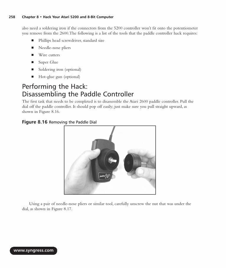
also need a soldering iron if the connectors from the 5200 controller won’t fit onto the potentiometeryou remove from the 2600.The following is a list of the tools that the paddle controller hack requires:
Phillips head screwdriver, standard size
Needle-nose pliers
Wire cutters
Super Glue
Soldering iron (optional)
Hot-glue gun (optional)
Performing the Hack: Disassembling the Paddle ControllerThe first task that needs to be completed is to disassemble the Atari 2600 paddle controller. Pull thedial off the paddle controller. It should pop off easily; just make sure you pull straight upward, asshown in Figure 8.16.
Using a pair of needle-nose pliers or similar tool, carefully unscrew the nut that was under thedial, as shown in Figure 8.17.
www.syngress.com
258 Chapter 8 • Hack Your Atari 5200 and 8-Bit Computer
Figure 8.16 Removing the Paddle Dial
287_HRD_HACK_08.qxd 1/13/04 7:36 PM Page 258

Flip the paddle controller over and remove the two screws with a Philips head screwdriver.Separate the two halves of the controller.
Pull out the paddle mechanism (the potentiometer, also known as a “pot”, as denoted in Figure8.18) and disconnect the two wires plugged into it. If the wires are soldered to the potentiometer,you’ll need to first desolder them.You’ll want to do this cleanly because we’ll be attaching two wiresfrom the 5200 controller when we transplant the potentiometer.
Now that you have the paddle controller disassembled, you’ll want to put aside the potentiometer,nut, and plastic dial (Figure 8.19).
www.syngress.com
Hack Your Atari 5200 and 8-Bit Computer • Chapter 8 259
Figure 8.17 Removing the Paddle Nut
Figure 8.18 Paddle Disassembled
287_HRD_HACK_08.qxd 1/13/04 7:36 PM Page 259
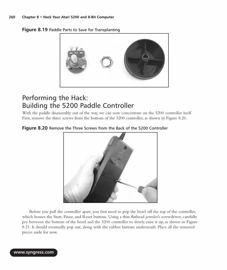
Performing the Hack: Building the 5200 Paddle ControllerWith the paddle disassembly out of the way, we can now concentrate on the 5200 controller itself.First, remove the three screws from the bottom of the 5200 controller, as shown in Figure 8.20.
Before you pull the controller apart, you first need to pop the bezel off the top of the controller,which houses the Start, Pause, and Reset buttons. Using a thin flathead jeweler’s screwdriver, carefullypry between the bottom of the bezel and the 5200 controller to slowly raise it up, as shown in Figure8.21. It should eventually pop out, along with the rubber buttons underneath. Place all the removedpieces aside for now.
www.syngress.com
260 Chapter 8 • Hack Your Atari 5200 and 8-Bit Computer
Figure 8.19 Paddle Parts to Save for Transplanting
Figure 8.20 Remove the Three Screws from the Back of the 5200 Controller
287_HRD_HACK_08.qxd 1/13/04 7:36 PM Page 260

Under the rubber buttons are traces mounted on a piece of thin, flexible plastic.This is part of amuch larger sheet that contains the traces for all the buttons in the controller, which you can see inFigure 8.22. Carefully slide this out from a slot on the left side of the controller.
WARNING: HARDWARE HARM
The 5200 controller contains a single, folded Mylar sheet with all the traces for the keypadbuttons, fire buttons, and Start, Reset, and Pause buttons. Care must be taken not to scratchor damage this flexible circuit or you may render your 5200 controller unusable.
www.syngress.com
Hack Your Atari 5200 and 8-Bit Computer • Chapter 8 261
Figure 8.21 Removing the Upper Bezel
Figure 8.22 Bottom Half of 5200 Controller
287_HRD_HACK_08.qxd 1/13/04 7:36 PM Page 261

You can now pull the two halves of the controller apart.There are two posts at the bottom of thecontroller, and you will need to lift the top half straight up in order to get the controller apart. Place thetop half of the controller with the joystick mechanism aside for now.The bottom of the controller con-tains two potentiometers—one that controls the horizontal motion and one that controls the verticalmotion. Both of these pots need to be removed, but they are glued to the base of the controller.Theeasiest way to remove them is to pry a thin, flathead screwdriver under the base of the mechanism andtwist the screwdriver, as shown in Figure 8.23.As the glue separates, you should hear it peeling.
Once you have popped out the potentiometers from the base of the controller, you can discon-nect the wires from the upper potentiometer and cut the wires where they exit the cable bundleentering the 5200 controller, since we won’t be needing them (Figure 8.24).
www.syngress.com
262 Chapter 8 • Hack Your Atari 5200 and 8-Bit Computer
Figure 8.23 Removing Pots
Figure 8.24 Removing Wires from the Upper 5200 Pot
287_HRD_HACK_08.qxd 1/13/04 7:36 PM Page 262

Concentrating on the bottom potentiometer, remove the middle connector and plug it into to themiddle connector of the potentiometer you removed from the 2600 paddle controller. Remove theother wire from the same 5200 pot and, while holding the 2600 pot with the plastic post face down andthe connectors pointed towards you, attach this wire to the right-most connector (Figure 8.25).You maybe able to slide the connectors on, but if they don’t fit you’ll have to solder them into place.
We’re done with the base—now we need to spend time on the upper half of the controllerwhich contains the joystick mechanism. We need to remove the joystick that is still attached to thishalf.A small, white, rectangular ball joint keeps the joystick from coming out. We need to cut thishousing along one edge so the joystick can then be pulled straight out.To do this, use a pair of wirecutters, a sharp knife, or a Dremel tool to cut through one side of the white plastic housing, as shownin Figure 8.26.Take care not to damage the two sliding plates (one is black, the other white) under-neath this housing, because we need those to complete the hack.
www.syngress.com
Hack Your Atari 5200 and 8-Bit Computer • Chapter 8 263
Figure 8.25 Wiring the 2600 Pot in Place of the Lower 5200 Pot
Figure 8.26 Freeing the Joystick
287_HRD_HACK_08.qxd 1/13/04 7:36 PM Page 263
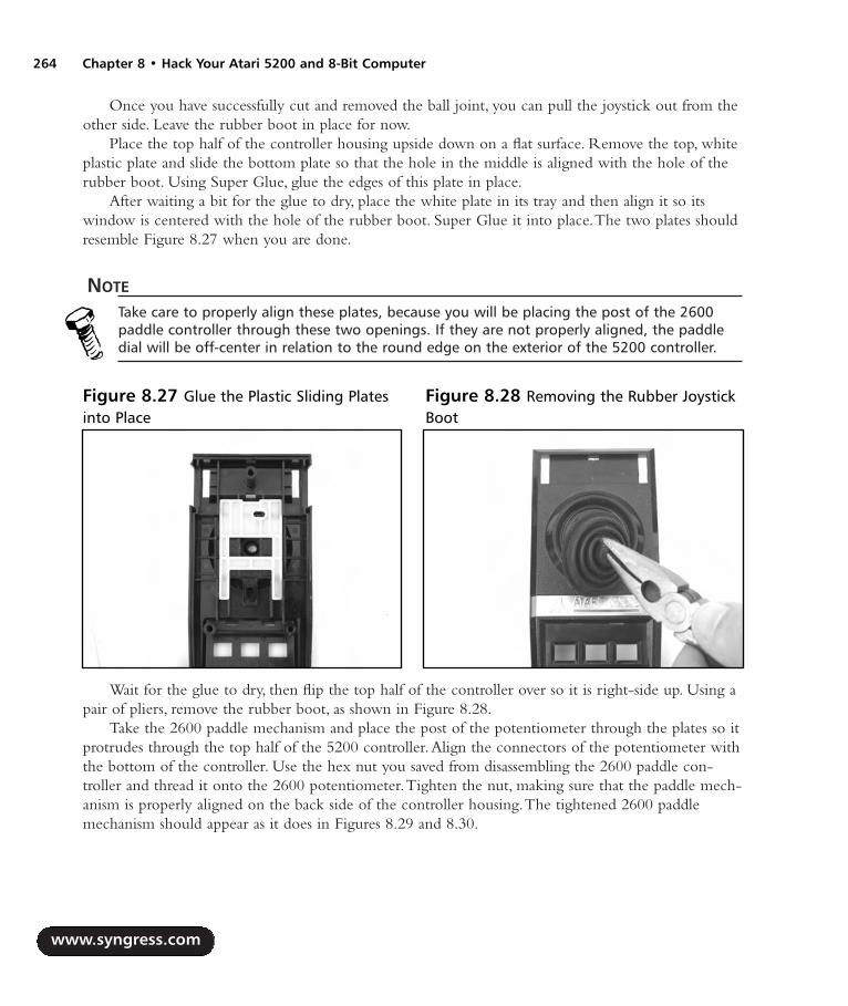
Once you have successfully cut and removed the ball joint, you can pull the joystick out from theother side. Leave the rubber boot in place for now.
Place the top half of the controller housing upside down on a flat surface. Remove the top, whiteplastic plate and slide the bottom plate so that the hole in the middle is aligned with the hole of therubber boot. Using Super Glue, glue the edges of this plate in place.
After waiting a bit for the glue to dry, place the white plate in its tray and then align it so itswindow is centered with the hole of the rubber boot. Super Glue it into place.The two plates shouldresemble Figure 8.27 when you are done.
NOTE
Take care to properly align these plates, because you will be placing the post of the 2600paddle controller through these two openings. If they are not properly aligned, the paddledial will be off-center in relation to the round edge on the exterior of the 5200 controller.
Wait for the glue to dry, then flip the top half of the controller over so it is right-side up. Using apair of pliers, remove the rubber boot, as shown in Figure 8.28.
Take the 2600 paddle mechanism and place the post of the potentiometer through the plates so itprotrudes through the top half of the 5200 controller.Align the connectors of the potentiometer withthe bottom of the controller. Use the hex nut you saved from disassembling the 2600 paddle con-troller and thread it onto the 2600 potentiometer.Tighten the nut, making sure that the paddle mech-anism is properly aligned on the back side of the controller housing.The tightened 2600 paddlemechanism should appear as it does in Figures 8.29 and 8.30.
www.syngress.com
264 Chapter 8 • Hack Your Atari 5200 and 8-Bit Computer
Figure 8.27 Glue the Plastic Sliding Platesinto Place
Figure 8.28 Removing the Rubber JoystickBoot
287_HRD_HACK_08.qxd 1/13/04 7:36 PM Page 264

You can now reassemble the controller.The easiest way to do this is to hold the top half of thecontroller upside down, place the rubber keypad buttons into the keypad holes, and then slide thethin Mylar film used for the Start, Pause, and Reset buttons through the slot at the top of the con-troller, as shown in Figure 8.31.
Carefully fit the two halves of the controller together, making sure not to pinch the Mylar film atthe top of the controller. Once the two halves are snug, you can then snap the Start, Pause, and Resetbuttons and their bezel into the top of the controller. Finally, place the paddle dial on top of thepotentiometer shaft. Before replacing the three screws that hold the controller together, you shouldtest the controller with an Atari 5200 game (Gorf, Kaboom!, Moon Patrol, or Breakout) to make sureit works.
www.syngress.com
Hack Your Atari 5200 and 8-Bit Computer • Chapter 8 265
Figure 8.29 Assembling the 2600Potentiometer
Figure 8.30 Inside the 5200 PaddleController
Figure 8.31 Assembling the Controller
287_HRD_HACK_08.qxd 1/13/04 7:36 PM Page 265
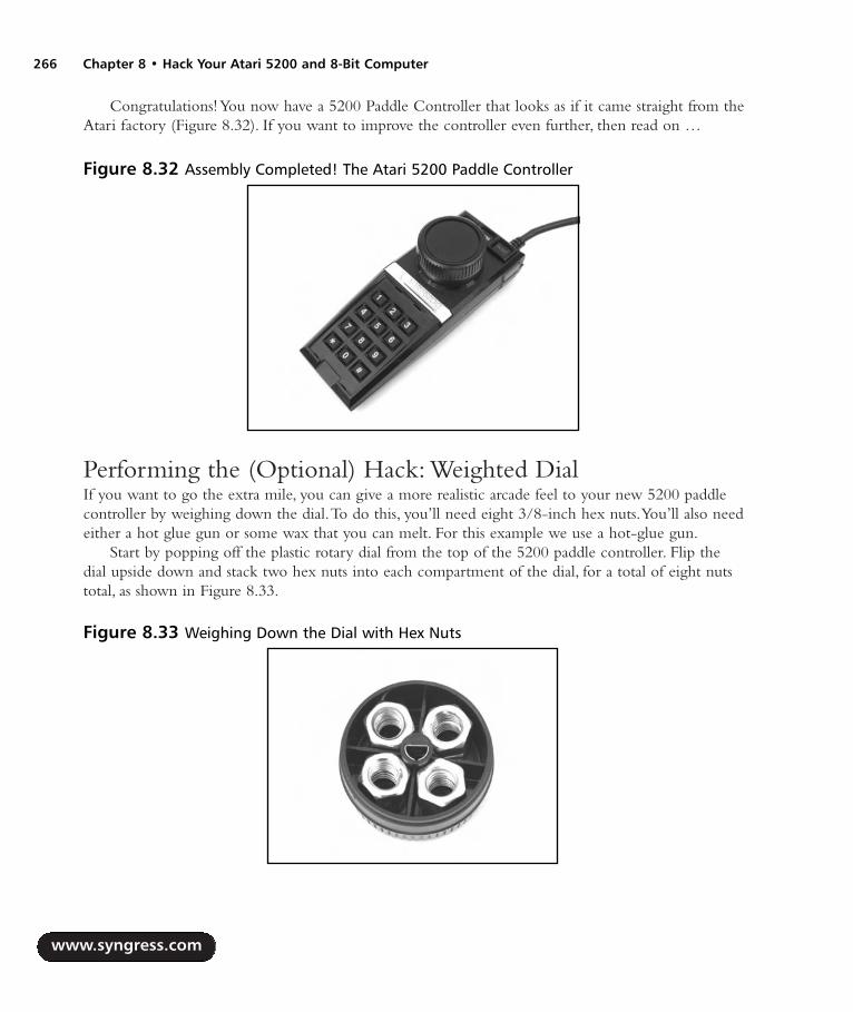
Congratulations! You now have a 5200 Paddle Controller that looks as if it came straight from theAtari factory (Figure 8.32). If you want to improve the controller even further, then read on …
Performing the (Optional) Hack: Weighted DialIf you want to go the extra mile, you can give a more realistic arcade feel to your new 5200 paddlecontroller by weighing down the dial.To do this, you’ll need eight 3/8-inch hex nuts.You’ll also needeither a hot glue gun or some wax that you can melt. For this example we use a hot-glue gun.
Start by popping off the plastic rotary dial from the top of the 5200 paddle controller. Flip thedial upside down and stack two hex nuts into each compartment of the dial, for a total of eight nutstotal, as shown in Figure 8.33.
www.syngress.com
266 Chapter 8 • Hack Your Atari 5200 and 8-Bit Computer
Figure 8.32 Assembly Completed! The Atari 5200 Paddle Controller
Figure 8.33 Weighing Down the Dial with Hex Nuts
287_HRD_HACK_08.qxd 1/13/04 7:36 PM Page 266

NOTE
Instead of using two 3/8” hex nuts in each compartment, you can substitute six penniesstanding vertically.
Using the hot-glue gun, fill the dial with a sufficient amount of glue to keep the nuts in place(Figure 8.34). Fill the center of the nuts and then the gaps around the sides of the nuts between theedges of each compartment.Try not to get glue on the top outer edge of the dial or in the centerhole where the dial attaches to the potentiometer.
After the glue has had time to set, reattach the dial to the controller.You now have a weighted5200 paddle controller that feels as though it belongs in an arcade!
Under the Hood: How the Hack WorksAlthough the Atari 8-bit computers (on which the Atari 5200 is based) use standard, digital con-trollers with four directions,Atari decided to “innovate” with the 5200 and design unique, analogcontrollers.These controllers allow 360 degrees of movement and variable movement in any directionby using two potentiometers.
A potentiometer is a variable resistor whose output is determined by the position of a “sweeper”that moves along a resistive strip.The resistance for each potentiometer in the 5200 controller rangesfrom 0 ohms to 500k ohms, with 250k ohms when the potentiometer is in the center position.As thesweeper moves, the resistance changes in a linear fashion, which is then read by the 5200 which cal-culates discrete values that the game software can read. One potentiometer is used for horizontal posi-tion and another is used for vertical position. Fortunately for us, the potentiometers in the 5200controller and the 2600 paddle controller can easily be swapped as they are the same physical size.
Since we’re only interested in horizontal movement, our modified 5200 controller only needs asingle potentiometer.This hack is made easier in that the 5200 controller housing seems to have been
www.syngress.com
Hack Your Atari 5200 and 8-Bit Computer • Chapter 8 267
Figure 8.34 Gluing the Nuts in Place
287_HRD_HACK_08.qxd 1/13/04 7:36 PM Page 267

designed with the potential for an official 5200 paddle controller, so retrofitting the 2600 paddle is apiece of cake.
What appears to be an actual Atari 5200 paddle controller (a CX-52P, versus the CX-52 for thestandard 5200 controller) has been found, but it’s unknown if this was indeed an official Atari proto-type or a controller that someone modified in similar fashion to the hack described in this chapter.
Free Yourself from the 5200 Four-Port SwitchboxWhen Atari designed the Atari 5200, they decided to create a unique TV/game switchbox that wouldnot only supply the audio/video signal to the television but also provide power to the 4-port 5200.The Atari 5200 power supply is plugged directly into the switchbox instead of the 5200, whichreduces cable clutter.Additionally, when power is applied to the 5200, the switchbox automaticallyswitches the video/audio signal from the antenna input of the TV to the 5200, saving the owner fromhaving to get up and manually slide a switch, as was required on most TV/game switchboxes (seeFigure 8.35) when the 5200 was released.
Figure 8.36 shows the switchbox that shipped with the 5200.The connector at the upper-rightcorner plugs into the 5200, feeding power to the 5200 and the RF signal back to the television.Theconnector at the bottom (near the sliding switch) is where the power is connected.
www.syngress.com
268 Chapter 8 • Hack Your Atari 5200 and 8-Bit Computer
Figure 8.35 Old style TV/Game Switchbox
287_HRD_HACK_08.qxd 1/13/04 7:36 PM Page 268

Although Atari’s intentions were noble, this proprietary switchbox precluded the use of a standardswitchbox since it was the only way to supply power to the 5200.This wasn’t a problem when Atariwas still producing the 5200, because replacement switchboxes were easy to come by, though moreexpensive than a standard switchbox. But, the most common problem today is finding a switchbox togo along with your 4-port 5200.Atari recognized the problems of this switchbox and ultimatelychanged it to a simpler design when they later introduced the two-port Atari 5200.
The hack in this section removes the four-port Atari 5200’s dependence on this specialswitchbox, allowing you to use a normal TV/game switchbox.As part of this hack, we’ll add a con-nector to the back of your 5200 where the 5200 power supply can be plugged directly in to the unit.
Preparing for the HackTo perform this hack you’ll need the parts shown in Figure 8.37.To mount the power connector tothe 5200 case, you’ll need two 7/16-inch metal washers to facilitate fitting the connector in the largerectangular hole at the back of the 5200 case. If you prefer, you can simply drill a 7/16-inch hole inthe back of the 5200 case, rendering the washers unnecessary and resulting in a slightly cleanerappearance. Some 3/16- and 3/32-inch heat-shrink tubing will also be used to shield the connectionson the power cable we’ll be building.
Size N power jack, 2.5” inner diameter, 5.5” outer diameter Radio Shack Part #274-1576
Metal washers (2), 7/16” inner diameter
47uF electrolytic capacitor, 35V or higher Radio Shack Part #272-1027
1N5391G rectifier diode — this part is difficult to obtain but the NTE5800 is a closematch and is what we will use to perform the hack (www.nteinc.com). You can also substi-tute a 1N4001 diode if you cannot find the others.
0.1uF ceramic capacitor, 50V Radio Shack Part #272-109
www.syngress.com
Hack Your Atari 5200 and 8-Bit Computer • Chapter 8 269
Figure 8.36 The Atari 5200 Four-Port Switchbox
287_HRD_HACK_08.qxd 1/13/04 7:36 PM Page 269
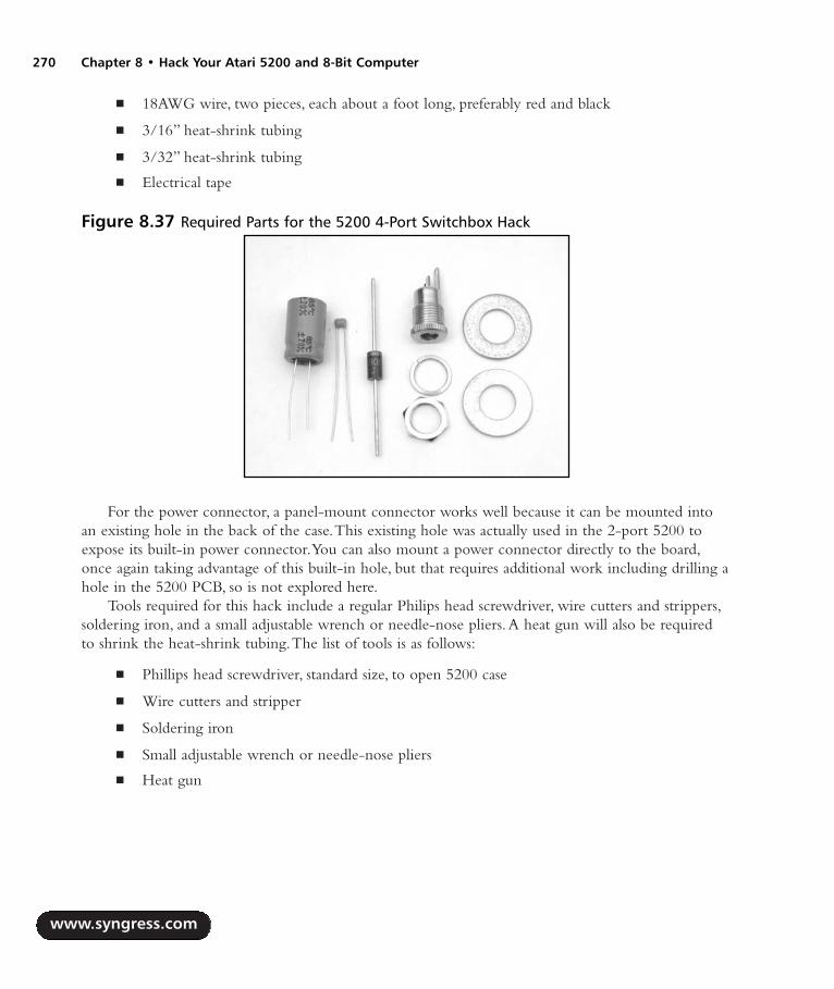
18AWG wire, two pieces, each about a foot long, preferably red and black
3/16” heat-shrink tubing
3/32” heat-shrink tubing
Electrical tape
For the power connector, a panel-mount connector works well because it can be mounted intoan existing hole in the back of the case.This existing hole was actually used in the 2-port 5200 toexpose its built-in power connector.You can also mount a power connector directly to the board,once again taking advantage of this built-in hole, but that requires additional work including drilling ahole in the 5200 PCB, so is not explored here.
Tools required for this hack include a regular Philips head screwdriver, wire cutters and strippers,soldering iron, and a small adjustable wrench or needle-nose pliers.A heat gun will also be requiredto shrink the heat-shrink tubing.The list of tools is as follows:
Phillips head screwdriver, standard size, to open 5200 case
Wire cutters and stripper
Soldering iron
Small adjustable wrench or needle-nose pliers
Heat gun
www.syngress.com
270 Chapter 8 • Hack Your Atari 5200 and 8-Bit Computer
Figure 8.37 Required Parts for the 5200 4-Port Switchbox Hack
287_HRD_HACK_08.qxd 1/13/04 7:36 PM Page 270

Performing the HackPlace the 5200 upside down on a flat surface, and remove the seven screws from the bottom.Thelocations of the screws are shown in Figure 8.38.
WARNING: HARDWARE HARM
The two screws at the top are shorter than the rest, so you’ll need to be careful to insert thelonger screws into the correct holes when reassembling the 5200. Failure to do so can resultin damage to the case, especially if you insert a long screw into a hole meant for one of theshorter screws.
Once you have the screws removed, you can slowly pull the case apart. Remove the 5200 PCBfrom the case and put the case aside for now. Figure 8.39 highlights the area of the PCB we’ll beworking on, in the upper-right corner.
www.syngress.com
Hack Your Atari 5200 and 8-Bit Computer • Chapter 8 271
Figure 8.38 Screw Locations of the Atari 5200
Figure 8.39 The 5200 Four-Port PCB
287_HRD_HACK_08.qxd 1/13/04 7:36 PM Page 271

Now that you have the 5200 board removed from the case, it’s time to warm up the solderingiron. We need to remove two components from the board: L8, a 2.7uH inductor located immediatelyto the left of the RF box, and C45, a large 4700uF electrolytic capacitor located just above the RFsocket. Both components are denoted in Figure 8.40.
WARNING: HARDWARE HARM
Care must be taken in removing the capacitor from the 5200. Because of the capacitor’slarge size and location on the board, you will only have access to the solder joints on thebottom side of the board. Remove as much solder as you can from the bottom of thesejoints, and slowly work out each of the capacitor’s leads by heating the joint and pulling upon the capacitor. Failure to do this carefully may result in traces being lifted from the frontside of the circuit board when you pull up the capacitor, thus damaging your system.
With these components removed, it’s time to build a cable that will connect the 5200 PCB withthe power connector that we’ll be attaching to the case. Start by cutting two lengths of 18-gaugewire, each about a foot long.The wires can be a bit shorter, but since the cable will be attached to thecase, but a longer length makes it easier to work on the board should you ever need to remove it. Ifpossible, use red and black wires (red for positive, black for ground).
Take the red wire and strip a short piece of insulation from each end. Solder the anode end (theside without the stripe) of the 1N5391G diode to one side of the wire.After you’ve soldered thediode to the wire, use a piece of small-diameter heat-shrink tubing to cover the exposed connection,as shown in Figure 8.41.
www.syngress.com
272 Chapter 8 • Hack Your Atari 5200 and 8-Bit Computer
Figure 8.40 Removing Two Components
287_HRD_HACK_08.qxd 1/13/04 7:36 PM Page 272
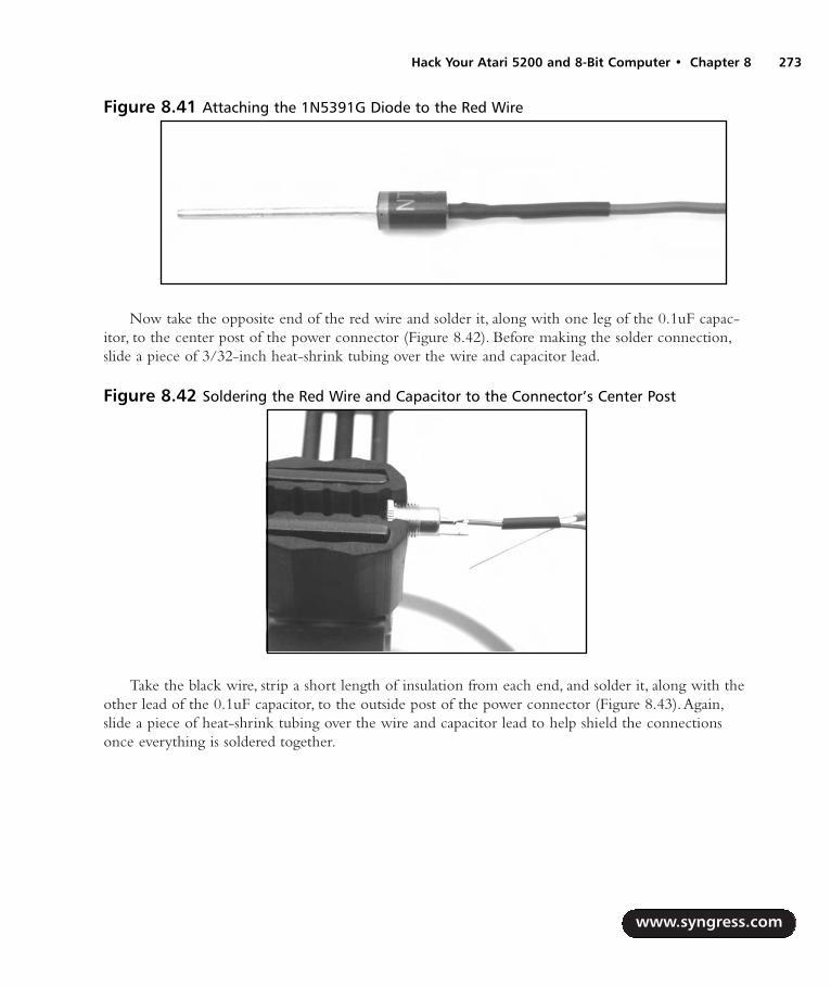
Now take the opposite end of the red wire and solder it, along with one leg of the 0.1uF capac-itor, to the center post of the power connector (Figure 8.42). Before making the solder connection,slide a piece of 3/32-inch heat-shrink tubing over the wire and capacitor lead.
Take the black wire, strip a short length of insulation from each end, and solder it, along with theother lead of the 0.1uF capacitor, to the outside post of the power connector (Figure 8.43).Again,slide a piece of heat-shrink tubing over the wire and capacitor lead to help shield the connectionsonce everything is soldered together.
www.syngress.com
Hack Your Atari 5200 and 8-Bit Computer • Chapter 8 273
Figure 8.41 Attaching the 1N5391G Diode to the Red Wire
Figure 8.42 Soldering the Red Wire and Capacitor to the Connector’s Center Post
287_HRD_HACK_08.qxd 1/13/04 7:36 PM Page 273

Slide the heat-shrink tubing over the terminals on the power connector and use a heat gun toshrink them down. Next, wrap electrical tape around any remaining exposed leads (such as from thecapacitor) to prevent any shorts.
WARNING: HARDWARE HARM
It’s important that any exposed wire and component leads be properly shielded so they donot come in contact with other components or wires. Because we are working on the 5200power input, electrical shorts can cause damage to the 5200 power supply or the systemboard, rendering your 5200 inoperable.
After that, cut and slide a piece of 3/16” heat-shrink tubing down from the opposite end of thecable over the end of the cable with the connector, covering everything from the power connectorterminals to the capacitor. Use the heat gun to shrink this tubing, as shown in Figure 8.44.
www.syngress.com
274 Chapter 8 • Hack Your Atari 5200 and 8-Bit Computer
Figure 8.43 Soldering the Black Wire and Capacitor to the Connector’s Outer Post
Figure 8.44 Building the Power Cable
287_HRD_HACK_08.qxd 1/13/04 7:36 PM Page 274

With the cable complete, we now need to attach the power connector to the bottom half of the5200 case. We’ll use the large, square hole between the edge of the case and the hole for the channelselect switch (which is marked with a square and circle on the case). Figure 8.45 shows which holewe’ll be using.
Slide one of the 7/16-inch washers over the cable and against the lip of the power connector.Then feed the cable through the hole in the 5200 case from the outside, as shown in Figure 8.46.
Once the washer is flush with the wall of the 5200 housing, push the other 7/16-inch washerover the cable until it is resting against the interior wall of the case.Then, take the nut that came withthe power adapter and screw it onto the adapter’s threads. Use a pair of pliers or an adjustable wrenchto tighten it.The connector should now resemble Figure 8.47.
www.syngress.com
Hack Your Atari 5200 and 8-Bit Computer • Chapter 8 275
Figure 8.45 Power Connector Hole
Figure 8.46 Power Connector: External View
287_HRD_HACK_08.qxd 1/13/04 7:36 PM Page 275

Now we can solder the other end of the newly added power cable to the Atari 5200 PCB. Solderthe cathode end (the side with the stripe) of the 1N5391G diode to the right solder pad of C45 (thelocation where you previously removed the 4700uF capacitor).After securing the diode to the board,bend it down as shown in Figure 8.48, as you’ll need to leave space to add the 47uF electrolyticcapacitor next to it. Solder the black wire to the right negative solder pad from C45, also shown inFigure 8.48.
Now, solder the 47uF electrolytic capacitor to the board using the adjacent set of solder pads forC45 (Figure 8.49).Take care to note polarity of the capacitor.The long lead is positive and must be
www.syngress.com
276 Chapter 8 • Hack Your Atari 5200 and 8-Bit Computer
Figure 8.47 Power Connector: Internal View
Figure 8.48 Soldering the Power Cable to the 5200 PCB
287_HRD_HACK_08.qxd 1/13/04 7:36 PM Page 276

placed through the solder pad adjacent to the diode.The shorter lead is negative (denoted with ablack stripe on the capacitor). Ensure that the capacitor has a good solder connection to the PCB.
The hack is now complete and should resemble the image in Figure 8.50.
You can now reassemble the 5200. Start by threading the 5200 RF cable through the hole in theback of the case and pushing the cable into the stress-release clip in the bottom of the case, as shownin Figure 8.51.
www.syngress.com
Hack Your Atari 5200 and 8-Bit Computer • Chapter 8 277
Figure 8.49 Adding the Capacitor to the 5200 PCB
Figure 8.50 Completed Power Supply Hack: Internal View
287_HRD_HACK_08.qxd 1/13/04 7:36 PM Page 277
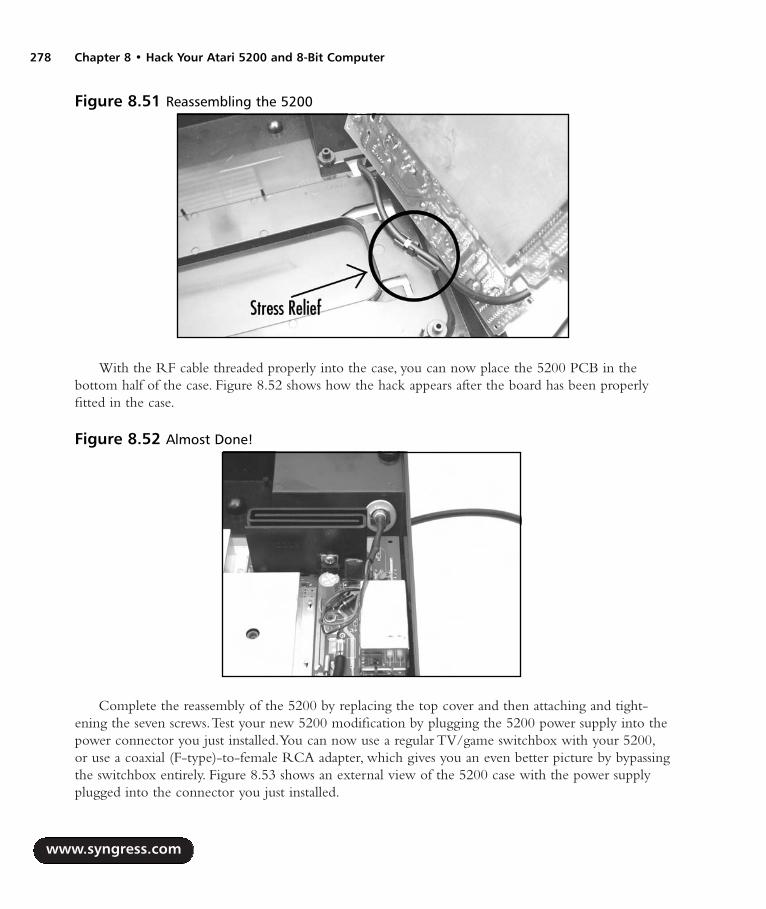
With the RF cable threaded properly into the case, you can now place the 5200 PCB in thebottom half of the case. Figure 8.52 shows how the hack appears after the board has been properlyfitted in the case.
Complete the reassembly of the 5200 by replacing the top cover and then attaching and tight-ening the seven screws.Test your new 5200 modification by plugging the 5200 power supply into thepower connector you just installed.You can now use a regular TV/game switchbox with your 5200,or use a coaxial (F-type)-to-female RCA adapter, which gives you an even better picture by bypassingthe switchbox entirely. Figure 8.53 shows an external view of the 5200 case with the power supplyplugged into the connector you just installed.
www.syngress.com
278 Chapter 8 • Hack Your Atari 5200 and 8-Bit Computer
Figure 8.51 Reassembling the 5200
Figure 8.52 Almost Done!
287_HRD_HACK_08.qxd 1/13/04 7:36 PM Page 278

Under the Hood: How the Hack WorksThis hack effectively mimics Atari’s modification of the two-port 5200 revision, where they removedthe reliance on the proprietary switchbox and installed a power connector into the 5200. Look atFigure 8.54 and you’ll see that Atari changed several power components from the four-port design,adding a power connector, diode, using a smaller capacitor, and removing the 2.7uH inductor.You canlook back at Figure 8.40 to compare this with the power section of the four-port board.
www.syngress.com
Hack Your Atari 5200 and 8-Bit Computer • Chapter 8 279
Figure 8.53 Give Me Power!
Figure 8.54 Power Supply Circuitry of the 2-Port Atari 5200 Showing Changes from the 4-Port Version
287_HRD_HACK_08.qxd 1/13/04 7:36 PM Page 279

Build Atari 8-Bit S-Video and Composite CablesMany models of the Atari 8-bit computer line contain a monitor port that allows you to connect thecomputer to a monitor or television using a composite video signal.Although this is a great improve-ment over the more commonly used RF output that combines video and audio frequencies into onesignal that must then be split apart (often poorly) by a television.The composite video signal can beimproved further with S-Video, which divides the video signal into two separate components, chromaand luminance, providing an even sharper video image. Several Atari 8-bit computers containing amonitor port can drive televisions that support S-Video inputs. Figure 8.55 shows the monitor andRF ports on an Atari 130XE computer.
Figure 8.56 shows the various connectors used for composite, S-Video, and the Atari 8-bit mon-itor port. Composite video generally uses a male RCA connector; S-Video has its own unique, four-pin mini-DIN connector; and the 8-bit monitor port uses a larger, five-pin DIN port.
www.syngress.com
280 Chapter 8 • Hack Your Atari 5200 and 8-Bit Computer
Figure 8.55 Atari 130XE Monitor, RF, and Power Jacks
Figure 8.56 Composite, S-Video, and Atari 8-Bit Monitor Connectors (Left to Right)
287_HRD_HACK_08.qxd 1/13/04 7:36 PM Page 280
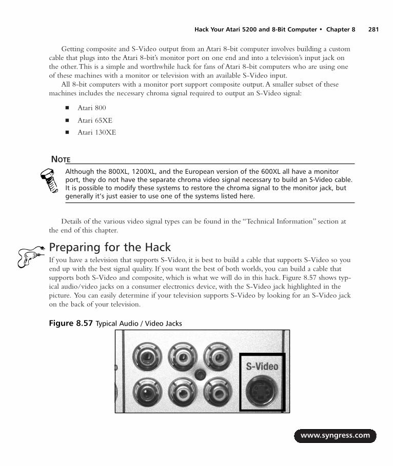
Getting composite and S-Video output from an Atari 8-bit computer involves building a customcable that plugs into the Atari 8-bit’s monitor port on one end and into a television’s input jack onthe other.This is a simple and worthwhile hack for fans of Atari 8-bit computers who are using oneof these machines with a monitor or television with an available S-Video input.
All 8-bit computers with a monitor port support composite output.A smaller subset of thesemachines includes the necessary chroma signal required to output an S-Video signal:
Atari 800
Atari 65XE
Atari 130XE
NOTE
Although the 800XL, 1200XL, and the European version of the 600XL all have a monitorport, they do not have the separate chroma video signal necessary to build an S-Video cable.It is possible to modify these systems to restore the chroma signal to the monitor jack, butgenerally it’s just easier to use one of the systems listed here.
Details of the various video signal types can be found in the “Technical Information” section atthe end of this chapter.
Preparing for the HackIf you have a television that supports S-Video, it is best to build a cable that supports S-Video so youend up with the best signal quality. If you want the best of both worlds, you can build a cable thatsupports both S-Video and composite, which is what we will do in this hack. Figure 8.57 shows typ-ical audio/video jacks on a consumer electronics device, with the S-Video jack highlighted in thepicture. You can easily determine if your television supports S-Video by looking for an S-Video jackon the back of your television.
www.syngress.com
Hack Your Atari 5200 and 8-Bit Computer • Chapter 8 281
Figure 8.57 Typical Audio / Video Jacks
287_HRD_HACK_08.qxd 1/13/04 7:37 PM Page 281

To perform this hack, you’ll need a cable with audio, composite video, and S-Video connectors onone end (the other end is not important, as we’ll be cutting it off ) as shown in Figure 8.58.You canpurchase this type of cable inexpensively from just about anywhere that sells videogames.The cablewe use in this example was purchased for $9.99 at Fry’s Electronics.You’ll also need a five-pin maleDIN connector, as shown in Figure 8.59.This connector will plug into the Atari 8-bit’s monitor port.The list of parts for this hack are as follows:
Five-pin male DIN connector, Fry's Electronics part# DIN-5-M
S-Video/composite/audio cable
3/16” diameter heat-shrink tubing, approximately 1” in length
4 pieces of 3/32” diameter heat-shrink tubing, approximately 1/4” in length
The tools required for this hack are as follows:
Wire cutters
Wire strippers
Soldering iron
Solder
Multimeter/Continuity tester
Performing the HackThe first step in the hack is to cut the connectors off the end of the audio/video cable that we won’tbe using (Figure 8.60). In this case, cut the cable before the junction where the connectors for thePlaystation, Dreamcast, and Nintendo 64 branch out.
www.syngress.com
282 Chapter 8 • Hack Your Atari 5200 and 8-Bit Computer
Figure 8.58 Combination S-Video/Composite/Audio Cable
Figure 8.59 A Five-Pin Male DINConnector
287_HRD_HACK_08.qxd 1/13/04 7:37 PM Page 282

Disassemble the five-pin DIN connector into its component parts.There should be a plasticsleeve; two metal halves that form the bulk of the connector, and a plastic disk that contains the pins(Figure 8.61).
Slide the plastic sleeve of the DIN connector, narrow end first, down the end of the cable youjust cut. Next, cut a 1” length of 3/16” heat-shrink tubing and slide it down the same end of thecable, as shown in Figure 8.62.
www.syngress.com
Hack Your Atari 5200 and 8-Bit Computer • Chapter 8 283
Figure 8.60 Pruning the Cable
Figure 8.61 Five-Pin DIN Connector Components
Figure 8.62 Preparing the Cable
287_HRD_HACK_08.qxd 1/13/04 7:37 PM Page 283
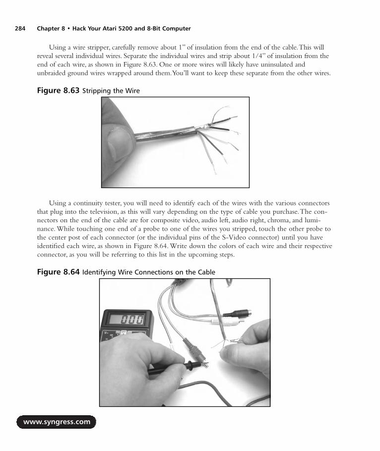
Using a wire stripper, carefully remove about 1” of insulation from the end of the cable.This willreveal several individual wires. Separate the individual wires and strip about 1/4” of insulation from theend of each wire, as shown in Figure 8.63. One or more wires will likely have uninsulated andunbraided ground wires wrapped around them.You’ll want to keep these separate from the other wires.
Using a continuity tester, you will need to identify each of the wires with the various connectorsthat plug into the television, as this will vary depending on the type of cable you purchase.The con-nectors on the end of the cable are for composite video, audio left, audio right, chroma, and lumi-nance. While touching one end of a probe to one of the wires you stripped, touch the other probe tothe center post of each connector (or the individual pins of the S-Video connector) until you haveidentified each wire, as shown in Figure 8.64. Write down the colors of each wire and their respectiveconnector, as you will be referring to this list in the upcoming steps.
www.syngress.com
284 Chapter 8 • Hack Your Atari 5200 and 8-Bit Computer
Figure 8.63 Stripping the Wire
Figure 8.64 Identifying Wire Connections on the Cable
287_HRD_HACK_08.qxd 1/13/04 7:37 PM Page 284
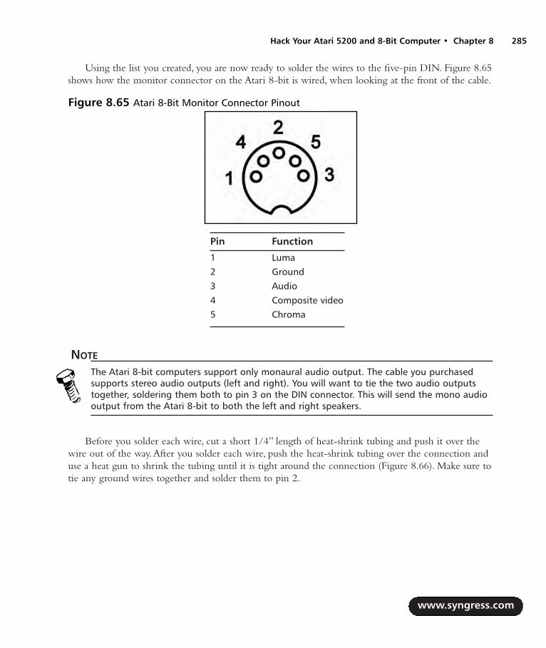
Using the list you created, you are now ready to solder the wires to the five-pin DIN. Figure 8.65shows how the monitor connector on the Atari 8-bit is wired, when looking at the front of the cable.
Pin Function
1 Luma2 Ground3 Audio4 Composite video5 Chroma
NOTE
The Atari 8-bit computers support only monaural audio output. The cable you purchasedsupports stereo audio outputs (left and right). You will want to tie the two audio outputstogether, soldering them both to pin 3 on the DIN connector. This will send the mono audiooutput from the Atari 8-bit to both the left and right speakers.
Before you solder each wire, cut a short 1/4” length of heat-shrink tubing and push it over thewire out of the way.After you solder each wire, push the heat-shrink tubing over the connection anduse a heat gun to shrink the tubing until it is tight around the connection (Figure 8.66). Make sure totie any ground wires together and solder them to pin 2.
www.syngress.com
Hack Your Atari 5200 and 8-Bit Computer • Chapter 8 285
Figure 8.65 Atari 8-Bit Monitor Connector Pinout
287_HRD_HACK_08.qxd 1/13/04 7:37 PM Page 285

Once you have finished soldering the individual wires to the DIN connector, slide the largerpiece of heat-shrink tubing back over the individual wires and use a heat gun to shrink the tubing, asshown in Figure 8.67.
Attach the two metal halves of the DIN connector over the pin housing. Each half of the DINconnector will fit in a groove, and the metal halves are keyed so they will only fit over the proper halfof the plastic pin housing. Figure 8.68 highlights one of the grooves with the plastic pin housingalready in place.
www.syngress.com
286 Chapter 8 • Hack Your Atari 5200 and 8-Bit Computer
Figure 8.66 Soldering the Five-Pin DIN
Figure 8.67 Adding Heat Shrink Tubing to the Cable
287_HRD_HACK_08.qxd 1/13/04 7:37 PM Page 286

Then, slide the plastic DIN connector sleeve over the two metal halves. Push the sleeve over themetal tab until you have pushed the hole in the plastic sleeve past the tab.This will keep the sleeve inplace so it will not slide backwards.The assembled monitor connector should resemble the image inFigure 8.69.
Your cable is now complete! Plug the monitor connector into your Atari 8-bit computer (Figure8.70) and then plug the S-Video or composite connector, as well as the audio connectors, into yourtelevision. Power the system up and you should now see a much sharper and more vibrant picturethan you previously experienced with your computer’s RF output.
www.syngress.com
Hack Your Atari 5200 and 8-Bit Computer • Chapter 8 287
Figure 8.68 Assembling the Connector
Figure 8.69 Assembled Monitor Connector
Figure 8.70 We’re Done! The Final Atari 8-Bit S-Video and Composite Cable
287_HRD_HACK_08.qxd 1/13/04 7:37 PM Page 287

Cable Hack AlternativesHere are some alternatives to building the hybrid composite/S-Video that we described in this section:
If you don’t need S-Video, you can create a more simple composite video/audio cable thatallows you to connect your 8-bit computer to a composite video source. Only the com-posite video and audio pins need to be connected, each soldered to an individual maleRCA connector.
Apple Desktop Bus (ADB) cables use the same type of connector as S-Video cables, so ifyou have any of these lying around, you can use them to build an S-Video cable.ADB isused to connect a keyboard and mouse to older model Macintosh and Apple IIgs com-puters.These cables are generally short and coiled, so this may not be a useful unless thetelevision or monitor you use with your 8-bit is fairly close to you (such as on a desk nearthe computer).
If you have a Commodore 1702 monitor, you can go one step further and build a cablewith three male RCA connectors, two for video and one for audio.The Commodore 1702has composite video and audio jacks on the front, but it also has another set of inputs on theback with separate chroma and luminance inputs (Figure 8.71).This is equivalent to havingan S-Video input, with two RCA connectors instead of the S-Video connector that iscommon on modern televisions.
Commodore 1702 monitors are popular with Atari 8-bit and vintage computer enthusiastsbecause of their excellent picture quality, support for S-Video via the chroma and lumi-nance connectors, convenient carrying handles on the sides, a flat top that allows for itemsto be placed on top of the monitor, and their reliable nature.
www.syngress.com
288 Chapter 8 • Hack Your Atari 5200 and 8-Bit Computer
Figure 8.71 Commodore 1702 Rear Input Jacks
287_HRD_HACK_08.qxd 1/13/04 7:37 PM Page 288

Under the Hood: How the Hack WorksThis hack works by building a cable that takes advantage of signals already exposed at the monitorport of the 800, 65XE, and 130XE computers. Composite Atari 8-bit monitor cables were fairly easyto come by back when Atari was producing the Atari 8-bit computers, but you’re much less likely toencounter them today, so if you want composite or S-Video output from your 8-bit, you’ll often needto resort to building your own cable. It’s unfortunate that Atari did not include the S-Video chromasignal on all Atari 8-bit machines with a monitor port, but at least two of the most common 8-bitmachines (800 and 130XE) have them.
Technical InformationThere are four common standards for transmitting a video signal to a television:
Component Video This is a relatively new method employed by the latest televisions,DVD players, and game systems to transmit high-quality video signals. It comprises of threesignals: one containing black and white picture information, or LUMA (Y), and two signalsCr and Cb, that contain matrixed color information to extract the Red and Blue pictureinformation from the Y signal.The Green picture information is what remains once the Redand Blue information is extracted.This is the preferred choice for hooking up consumer-grade video components. Component video connectors are generally RCA jacks, oftenlabeled Y, Cr, and Cb.
S-Video S-Video output is split into two signals: one containing the black and white pic-ture information, LUMA (Y), and another signal, CHROMA (C), that contains all the colorinformation. S-Video connectors are now standard on most televisions, DVD players, digitalvideo recorders, and other consumer video equipment.An S-Video connector is a small,four-pin mini-DIN. S-Video is sometimes labeled Y-C.
Composite Video Composite video output contains a single signal of all brightness, color,and timing information. Due to this combination of signals, it is impossible for the video tobe reconstructed without noticeable artifacts. Composite video generally consists of a singleRCA jack, usually yellow to differentiate it from audio jacks (which are generally red andwhite).
RF (Radio Frequency) In addition to containing the video signal, RF also introducesaudio into the signal and is the lowest-quality method of signal distribution to a television.RF is most commonly used to broadcast television signals via over-the-air transmission(picked up with an antenna) or via cable television. RF is capable of carrying a wide rangeof video and audio signals on different frequencies on a single wire and is prone to interfer-ence from many sources. RF jacks on televisions and other equipment usually employ acoaxial F-type adapter. Older televisions may not even have a coaxial jack, instead using twoscrews to which a switchbox or antenna is attached to..
www.syngress.com
Hack Your Atari 5200 and 8-Bit Computer • Chapter 8 289
287_HRD_HACK_08.qxd 1/13/04 7:37 PM Page 289

Although Component Video is beginning to be used more, S-Video is still much more common.RF should be avoided whenever possible due to the poor signal quality, although it is difficult to doso when working with old videogame systems and vintage computers built in the 1970s and ’80s.Because of the inherent problems with RF signals, hacking old systems to add composite or S-Videooutput is fairly common and well worth the effort.
It is interesting to note that although the Atari 8-bit computers had support for S-Video as farback as 1979 with the Atari 800, it wasn’t until the release of the Atari Jaguar in 1994 that an Atarigame console had official S-Video support (through purchase of an Atari-branded cable).
Other HacksThe hacks presented within this chapter are only the beginning of what you can do with your oldgaming systems and computers. We’ve listed some more complex and advanced hacks here; anddetailed instructions for many of these are available on the Internet. Whenever possible we’ve pointedyou towards resources for additional information.
Atari 5200 Four-Port VCS Cartridge Adapter FixIn order to make the Atari 5200 model more attractive to consumers,Atari eventually developed aVCS cartridge adapter to allow 2600 games to be used with the 5200.This adapter plugs into the5200 cartridge port and contains a slot to accept 2600 cartridges, two controller ports, and the variousswitches found on a regular 2600 console.All two-port models of the Atari 5200 accept this adapterwithout problems. However, the original 4-port Atari 5200 model is incompatible with the VCSadapter, except in rare cases (see the following note).Atari quickly released a technical bulletin andcomponent kit to allow dealers to correct the problem with incompatible units.
NOTE
Not all Atari 5200 four-port models suffer from the incompatibility problem with the VCS car-tridge adapter. If the serial number for your Atari 5200 contains an asterisk (*), then the VCScartridge adapter will work in your 5200 without modifications. It’s unclear how many suchmodels exist, but it seems only a small portion of four-port 5200 models fall into this category.
You can find scans of the original Atari Service Bulletin so you can perform this hack on yourfour-port 5200 at www.atariage.com/5200/archives/VCSFix.
Atari 5200 Composite/S-Video ModificationLike most videogame systems at the time, the Atari 5200 only supported an RF connection to thetelevision. Better quality output can be had by way of a composite or S-Video mod to your 5200,allowing you to use the composite video and S-Video jacks on your television. Section 4.13 of theAtari 5200 FAQ (www.atariage.com/5200/faq.html?SystemID=5200) contains information on howto do the modification.
www.syngress.com
290 Chapter 8 • Hack Your Atari 5200 and 8-Bit Computer
287_HRD_HACK_08.qxd 1/13/04 7:37 PM Page 290

Atari 8-Bit SIO2PC CableThe Atari 8-bit computers, via its SIO (Serial I/O) port, can be interfaced with a PC to simulate var-ious peripherals, such as disk drives and printers.You can boot your Atari 8-bit directly from fileslocated on your PC and you can print to your PC printer from your Atari 8-bit! The Atari computerwill never know that you’ve secretly switched real peripherals with a simple cable that plugs into yourPC’s serial port.This is one of the most useful mods you can perform on your 8-bit computer.
A thorough SIO2PC FAQ can be found at www.tcainternet.com/wa5bdu/siofaq.htm, whichshould answer all your questions about the SIO2PC and also provides links to schematics and software.
Another useful program to have is Atari810, a disk drive emulator that can be used with anSIO2PC cable: http://retrobits.net/atari810.html.You can also build a ready-to-use SIO2PC cablefrom AtariAge (www.atariage.com/store/product_info.php?products_id=141).
Atari Resources on the WebA large number of Web sites are dedicated to Atari game systems and computers.There is a large listat the end of the Hack Your Atari 2600 and 7800 chapter to get you started. We listed several of ourfavorite sites at the end of Chapter 7 to get you started.
www.syngress.com
Hack Your Atari 5200 and 8-Bit Computer • Chapter 8 291
287_HRD_HACK_08.qxd 1/13/04 7:37 PM Page 291

287_HRD_HACK_08.qxd 1/13/04 7:37 PM Page 292

Hacking thePlayStation 2
Hacks in this Chapter:
Getting Inside the PS2
Installing a Serial Port
Booting Code from the Memory Card
Other Hacks: More Independent Hard Drives
Chapter 9
293
287_HRD_HACK_09.qxd 1/14/04 1:43 PM Page 293

IntroductionWith over 60 million consoles sold worldwide as of August 2003, Sony’s PlayStation 2 (PS2) has thelargest user base of the current generation of gaming consoles. Surprisingly, the PS2 has the leastamount of hardware hacks and homebrew software projects, compared to Microsoft’s Xbox or Sega’snow defunct Dreamcast.There is an active community of PS2 homebrew software developers, but itssize doesn’t compare to the number of Xbox or Dreamcast homebrew hackers. Outside of “modchip”manufacturers, very few hardware hackers are dedicated to exposing the PS2’s internals.
One of the reasons that not a lot of hardware hacking is done on the PS2 is that a large numberof the talented individuals who decide to reverse-engineer the PS2’s hardware are modchip manufac-turers.These manufacturers guard the information they find as trade secrets, rarely revealing informa-tion to the public (usually providing just enough detail to allow a user to install the modchip).Another reason is that even though the PS2 contains a few standard connections such as USB andIEEE1394, internally the PS2 is vastly different from other “standard” architectures such as the PCarchitecture that the Xbox is based on.A lot more work is involved in locating and snooping the databuses and determining the signals output by the custom chips found on the PS2’s mainboard.
Commercial Hardware Hacking: ModchipsFor all consoles, software piracy is a thriving business.Although console manufacturers implementsecurity features that make it difficult or impossible for the average gamer to copy games, hardwarehackers employ seasoned techniques to make short work of defeating hardware security methods.Such techniques include snooping the system’s data bus with a logic analyzer and dumping an imageof the BIOS to look for software workarounds. Once just simple shims to allow a user to play unau-thorized copies of games, modchips are now complex devices that allow much more.
When a viable set of exploits and workarounds is found to bypass a particular security feature, themodchip is born. Modchips are small printed circuit boards (PCBs) with wires that attach to variouscomponents on the console’s main board.A modchip is usually controlled by a Microchip PIC orstandard programmable logic (such as a programmable logic device [PLD]), but modern modchips forthe PS2 and other systems include an FPGA and Flash ROM so that they can be updated with bugfixes and new features. Normally, a modchip sends a signal to the console’s security system to fool thesystem into thinking the user has inserted a valid game disc. Modchips can also bypass other systems,including code in the BIOS, or the default video mode (PAL or NTSC) output by the console’sgraphics hardware.
On the PS2, modchips are primarily used to bypass the hardware authentication performed onPS1 and PS2 game discs.They also are used to patch the BIOS to disable Macrovision for recordingDVD content to a VCR, to enable region-free DVD playback, and to override the video mode usedby games in other regions (for example, playing PAL games on an NTSC system).The original PS2modchips were crude, simple devices that could only bypass PS1 game disc authentication and facili-tate a “swap trick” for PS2 game discs only if the user had bought a separate and unsupported bootdisc.These boot discs (written and sold by unlicensed third-party vendors) contain code to stop thePS2’s DVD drive from spinning. Once the drive has spun down, the user forces the drive open, using
www.syngress.com
294 Chapter 9 • Hacking the PlayStation 2
287_HRD_HACK_09.qxd 1/14/04 1:43 PM Page 294

Hacking the PlayStation 2 • Chapter 9 295
a special case modification (called a fliptop) or sometimes using a plastic knife or a credit card-sizeddevice.The user then puts in the copied PS2 game and closes the drive, and the PS2’s hardwareauthentication will be defeated, having failed to detect the forced opening and closing of the drive.
The main disadvantage of physical swapping is that using an object to force open the PS2’s DVDdrive can shorten the life of the drive. Modern modchips have done away with the destructive swapmethod by authenticating a copied PS2 game disc directly in hardware. Some of these modchipsinclude an FPGA and Flash memory so that users can apply bug fixes and add new features by simplybooting a disc.They also include a special loader that executes a program stored on the PS2 memorycard when the PS2 is powered on.This program is usually another loader, but with a graphical userinterface (GUI) for running other programs and utilities for installing programs to the memory cardor a hard drive from a CD. Figure 9.1 shows the LisaZero PAL-only modchip, which uses aQuickLogic PLD that contains fixed boot code.
The engineers and hackers behind commercial modchips invest a lot of time and money reverse-engineering the hardware and testing their findings.The low-level information that they discover israrely (if ever) shared with the public, since by doing so they would lose their edge over competingmanufacturers. Other modchip makers can still offer the same or similar features by reverse engi-neering a competing modchip or using the same techniques to document the hardware.Althoughsome of the information they discover is only useful to someone who wants to bypass PS2 hardwaresecurity, most of the information would benefit anyone who wanted to develop their own hardwareor software for the PS2.This information includes the pinouts and signals of the PS2’s processors andbuses, expansion port, and BIOS.
Not having this information available to everyone stifles the PS2 hardware-hacking and home-brew development communities.As presented later in this chapter, some of the hidden hardwareinformation enables the PS2 developer to gain better control over the system and access to powerfuldebugging methods. My main motivation for releasing the Independence exploit (see the “Booting
www.syngress.com
Figure 9.1 The LisaZero “No-Swap” Modchip
287_HRD_HACK_09.qxd 1/14/04 1:43 PM Page 295
Code from the Memory Card” section) was to allow anyone interested in writing PS2 software to doso without having to physically modify their console.
NEED TO KNOW…Some sections of this chapter contain source code examples. Unless specified otherwise, allexamples were written for use with PS2Lib, an Open Source library for the PS2. You canobtain PS2Lib from http://ps2dev.sourceforge.net/ps2lib.html.
A couple of comments on the conventions used in the code:
PS2Lib’s tamtypes.h header defines the basic types used on the PS2. A u fol-lowed by a number indicates an unsigned type with the specified number ofbits, and an s followed by a number indicates a signed type. For example, s8indicates an 8-bit signed integer and u32 indicates a 32-bit unsigned integer.
tamtypes.h also defines macros for convenient access to hardware registers.These macros are similar to the inb() and outb() style macros found in low-levelPC programming. The _lw() macro is a synonym for the MIPS lw instruction,which returns a 32-bit value read from the given address (the address is speci-fied as an unsigned 32-bit integer). Likewise, the _sw() macro stores a 32-bitvalue to the given address. Each of these macros represents the correspondingMIPS instruction, so there are _lb()/_sb(), _lh()/_sh(), and _ld()/_sd() macros forreading and writing 8-bit, 16-bit, and 64-bit values, respectively.
Getting Inside the PS2The following is a guide to identifying your PS2’s mainboard revision and steps to disassemble the PS2.
Mainboard RevisionsAt this writing, there are 11 known major revisions of the PS2 mainboard and about a dozen BIOSrevisions. Mainboard revisions are usually denoted with V (for version), followed by the major revi-sion number—for example, V7.The revision number is commonly referred to as just the PS2 versionnumber. Numbering starts at V0, which is the version of the original PS2 launched in Japan.There isno notation for minor revisions.
There are a number of reasons that Sony would want to revise the PS2 internally:
To fix hardware and software bugs
To move separate peripherals onto a single chip to lower manufacturing costs
To implement new security measures to keep attackers out
The problem with major mainboard revisions is that the physical layout of the board and its com-ponents changes from one revision to the next.This means that the instructions for locating a partic-ular component or testpoint will be different on a V1 than on a V7. Some revisions have a close
www.syngress.com
296 Chapter 9 • Hacking the PlayStation 2
287_HRD_HACK_09.qxd 1/14/04 1:43 PM Page 296
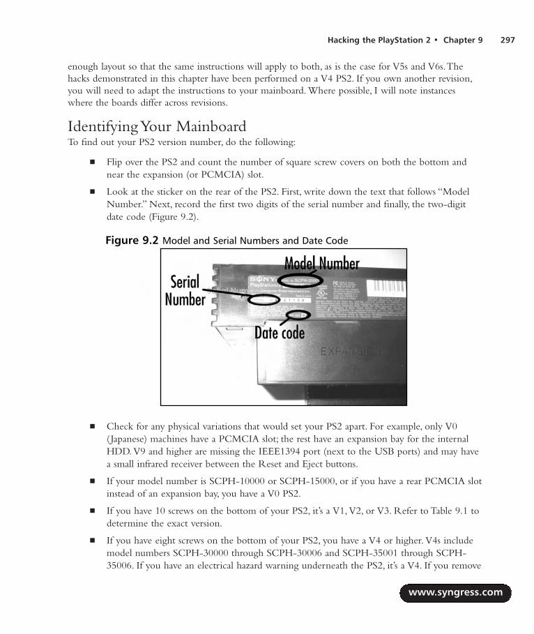
Hacking the PlayStation 2 • Chapter 9 297
enough layout so that the same instructions will apply to both, as is the case for V5s and V6s.Thehacks demonstrated in this chapter have been performed on a V4 PS2. If you own another revision,you will need to adapt the instructions to your mainboard. Where possible, I will note instanceswhere the boards differ across revisions.
Identifying Your MainboardTo find out your PS2 version number, do the following:
Flip over the PS2 and count the number of square screw covers on both the bottom andnear the expansion (or PCMCIA) slot.
Look at the sticker on the rear of the PS2. First, write down the text that follows “ModelNumber.” Next, record the first two digits of the serial number and finally, the two-digitdate code (Figure 9.2).
Check for any physical variations that would set your PS2 apart. For example, only V0(Japanese) machines have a PCMCIA slot; the rest have an expansion bay for the internalHDD. V9 and higher are missing the IEEE1394 port (next to the USB ports) and may havea small infrared receiver between the Reset and Eject buttons.
If your model number is SCPH-10000 or SCPH-15000, or if you have a rear PCMCIA slotinstead of an expansion bay, you have a V0 PS2.
If you have 10 screws on the bottom of your PS2, it’s a V1, V2, or V3. Refer to Table 9.1 todetermine the exact version.
If you have eight screws on the bottom of your PS2, you have a V4 or higher. V4s includemodel numbers SCPH-30000 through SCPH-30006 and SCPH-35001 through SCPH-35006. If you have an electrical hazard warning underneath the PS2, it’s a V4. If you remove
www.syngress.com
Figure 9.2 Model and Serial Numbers and Date Code
287_HRD_HACK_09.qxd 1/14/04 1:43 PM Page 297

your expansion bay cover and notice a metal shield on the inside of the cover, you mostlikely have a V4.
V5 or V6 PS2s (there aren’t a lot of differences between these internally) use model num-bers SCPH-30000R through SCPH-30006 R (note the space) or SCPH-30000 throughSCPH-30004.To distinguish a V5 or V6 from a V4, remove the expansion bay cover andlook for a small screw at the top of the expansion bay, closest to its left side. If this screw isthere, you have a V5 or V6.Also check the inside of the expansion bay cover. If it’s plastic,chances are you have a V5 or V6.
If your model number includes SCPH-39000 through SCPH-39004 or SCPH-37000, youhave a V7.
If your PS2 is from Japan and your model number is SCPH-39000 or SCPH-39006, youmight have a V8 PS2. I don’t know of any major differences on the mainboard between V7sand V8s.
If your model number includes SCPH-50000 through SCPH-50004 and your date code isnot 3D, you have a V9 PS2. If your date code is 3D, you have a V10. V9s and V10s are alsomissing the IEEE1394 port and may have an infrared receiver sandwiched between theReset and Eject buttons.
Table 9.1 Identifying V1, V2, and V3 PS2s
Version Serial Number (First Two Digits) Date Code
V1 U1 0DV2 U0 0DV3 U1 1AV3 U2 0D
Opening the PS2Our first hack is performed on the bottom of the PS2’s mainboard. Opening the PS2 and exposingthe mainboard can be tricky if you’ve never done it before.The following instructions apply to V4PS2s, so you may have to modify them slightly for PS2s made after the V4. If you own a V3 or ear-lier, some of the later steps may not apply at all.
www.syngress.com
298 Chapter 9 • Hacking the PlayStation 2
287_HRD_HACK_09.qxd 1/14/04 1:43 PM Page 298

WARNING: HARDWARE HARM
The PS2 mainboard and connected assemblies contain many electrostatic-sensitive compo-nents. You must always be grounded before touching the inside of your PS2 or you risk dam-aging these components. The easiest way to ground yourself is to buy an anti-static wriststrap and connect it to a grounded source. If you do not have a wrist strap, you can groundyourself by touching a piece of metal (such as the edge of your desk) before touching theinside of your PS2.
1. Turn the PS2 over so the bottom is facing up.You should notice either eight or 10 squareindentations; these are covers for the case screws. Using either your fingernail or a small flat-head screwdriver, pry up each of these covers to expose the screws (Figure 9.3).
2. Using a Phillips screwdriver, remove the case screws.You may meet some resistance becausethe screws could be glued shut. Just turn them counter-clockwise until you hear a snap andthe screw should easily turn the rest of the way.
3. If you have a warranty sticker (usually found next to the A/V connector on the back),remove it.
4. Flip the PS2 back over and face the front of the PS2 away from you.The expansion bayshould be to your left and the A/V connector to your right. Slowly lift the top half of thecase.You will have to move it slightly forward to remove it from the joypad assembly andthe DVD drive. Be careful not to lift the case too fast, since it is still connected to theReset/Eject button assembly. See Figure 9.4 for details.
www.syngress.com
Hacking the PlayStation 2 • Chapter 9 299
Figure 9.3 Removing the Plastic Screw Covers
287_HRD_HACK_09.qxd 1/14/04 1:43 PM Page 299
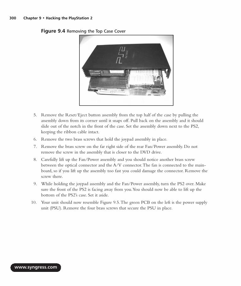
5. Remove the Reset/Eject button assembly from the top half of the case by pulling theassembly down from its corner until it snaps off. Pull back on the assembly and it shouldslide out of the notch in the front of the case. Set the assembly down next to the PS2,keeping the ribbon cable intact.
6. Remove the two brass screws that hold the joypad assembly in place.
7. Remove the brass screw on the far right side of the rear Fan/Power assembly. Do notremove the screw in the assembly that is closer to the DVD drive.
8. Carefully lift up the Fan/Power assembly and you should notice another brass screwbetween the optical connector and the A/V connector.The fan is connected to the main-board, so if you lift up the assembly too fast you could damage the connector. Remove thescrew there.
9. While holding the joypad assembly and the Fan/Power assembly, turn the PS2 over. Makesure the front of the PS2 is facing away from you.You should now be able to lift up thebottom of the PS2’s case. Set it aside.
10. Your unit should now resemble Figure 9.5.The green PCB on the left is the power supplyunit (PSU). Remove the four brass screws that secure the PSU in place.
www.syngress.com
300 Chapter 9 • Hacking the PlayStation 2
Figure 9.4 Removing the Top Case Cover
287_HRD_HACK_09.qxd 1/14/04 1:43 PM Page 300

11. The PSU is also connected to the PS2 mainboard with a four-pronged connector. Carefullylift the PSU to disconnect it.You should notice a small two-wire connector going from thefan to the mainboard. Pull straight up on this connector, grabbing the wires that are theclosest to the mainboard connector. Set the PSU and Fan/Power assembly aside.
12. Remove the plastic sheet on top of the metal casing.Also remove the metal housing for theinternal hard drive. See Figure 9.6.
13. Remove the eight tiny brass screws.There are four of these screws underneath the plasticsheet.Two more screws secure the expansion bay connector, and two more are along theright side of the metal casing, above the DVD drive. Remove the tiny black screw locatedunderneath the DVD drive.
14. The large metal casing is attached to the DVD drive with two tabs closest to you and onetab in the front. Pry these tabs and carefully lift up the metal casing.
www.syngress.com
Hacking the PlayStation 2 • Chapter 9 301
Figure 9.5 The Bottom of PS2 and PSU
Figure 9.6 Bottom Metal Casing
287_HRD_HACK_09.qxd 1/14/04 1:43 PM Page 301
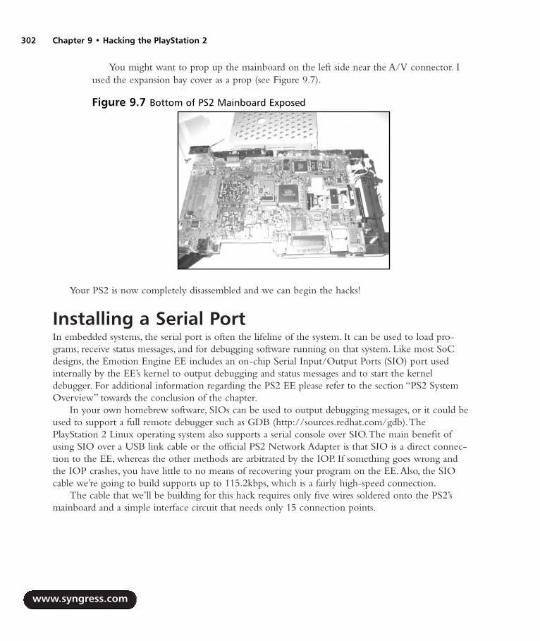
You might want to prop up the mainboard on the left side near the A/V connector. Iused the expansion bay cover as a prop (see Figure 9.7).
Your PS2 is now completely disassembled and we can begin the hacks!
Installing a Serial PortIn embedded systems, the serial port is often the lifeline of the system. It can be used to load pro-grams, receive status messages, and for debugging software running on that system. Like most SoCdesigns, the Emotion Engine EE includes an on-chip Serial Input/Output Ports (SIO) port usedinternally by the EE’s kernel to output debugging and status messages and to start the kerneldebugger. For additional information regarding the PS2 EE please refer to the section “PS2 SystemOverview” towards the conclusion of the chapter.
In your own homebrew software, SIOs can be used to output debugging messages, or it could beused to support a full remote debugger such as GDB (http://sources.redhat.com/gdb).ThePlayStation 2 Linux operating system also supports a serial console over SIO.The main benefit ofusing SIO over a USB link cable or the official PS2 Network Adapter is that SIO is a direct connec-tion to the EE, whereas the other methods are arbitrated by the IOP. If something goes wrong andthe IOP crashes, you have little to no means of recovering your program on the EE.Also, the SIOcable we’re going to build supports up to 115.2kbps, which is a fairly high-speed connection.
The cable that we’ll be building for this hack requires only five wires soldered onto the PS2’smainboard and a simple interface circuit that needs only 15 connection points.
www.syngress.com
302 Chapter 9 • Hacking the PlayStation 2
Figure 9.7 Bottom of PS2 Mainboard Exposed
287_HRD_HACK_09.qxd 1/14/04 1:43 PM Page 302

Preparing for the HackTable 9.2 lists the parts required to build the SIO cable and interface board and Figure 9.8 shows apicture of the components.You can order samples of Maxim’s MAX3323EEPE from the company’sWeb site (www.maxim-ic.com). Be sure to order the DIP version of the chip.The rest of the partscan be found locally at Radio Shack or online at many electronics distributors.
Table 9.3 shows the wire colors I chose for the connections.
Table 9.2 Parts List
Quantity Part Comments
1 MAX3323EEPE Maxim, www.maxim-ic.com5 0.1µF monolythic capacitors Radio Shack part# 272-1091 Female DB9 connector1 Plastic DB9 hood1 Sixteen-pin IC socket Radio Shack part# 276-19981 PC board Radio Shack part# 276-1485 30AWG wire Approximately 12” in length1 DB9 serial cable Optional1 Five-pin plastic male and Optional
female connectors
www.syngress.com
Hacking the PlayStation 2 • Chapter 9 303
Figure 9.8 Required Parts for SIO Cable
287_HRD_HACK_09.qxd 1/14/04 1:43 PM Page 303

Table 9.3 Serial Cable Wire Colors
Color Signal
Red +3.3V (VCC)Black Ground (GND)White EE core voltage (VCORE)Blue EE_TXD and PC_TXDGreen EE_RXD and PC_RXD
Performing the Hack
WARNING: HARDWARE HARM
The PS2 mainboard contains many heat-sensitive surface-mount components. Never use asoldering iron that is higher than 15 watts. If you have a variable-watt iron, make sure thatit’s set to 15 watts before you begin soldering.
The bottom side of your PS2’s mainboard should be exposed, with the A/V connector closest toyou and the memory card connector facing away from you. See the preceding “Getting Inside YourPS2” section for details on how to get to your mainboard. If you have a V4 or higher mainboard, youshould be looking at something similar to Figure 9.7. We’ll start with the wires that connect the PS2side of the serial cable:
1. Locate the +3.3V pad. Figure 9.9 shows the location on a V4 mainboard. Most modchipinstallation Web sites (such as www.dms3.com) show the +3.3V location for your specificmainboard version. Solder one end of the red wire to this point.
www.syngress.com
304 Chapter 9 • Hacking the PlayStation 2
Figure 9.9 Location of the +3.3V (VCC) Pad
287_HRD_HACK_09.qxd 1/14/04 1:43 PM Page 304

2. On the left side of the mainboard, you should see printed text including “GH-” followed bya three-digit number. Somewhere in this area is a silver rectangle we’ll use for ground.Figure 9.14 shows this location.You may see oxidation (small brown spots) on the rectangle.Solder one end of the black wire to this point.
3. The area to the right of the text is directly beneath the EE (which is mounted on the otherside).You should see many small capacitors surrounding the area and several large ones posi-tioned in the center. Look at the upper-right corner of the EE and you should notice foursmall silver square-shaped pads positioned in a vertical line.There will be a gap in betweenthe top pad and the bottom three.This is the EE’s SIO port as denoted in Figure 9.10.
4. The first point that we’ll connect from the EE SIO will be our most difficult one: theEE_RXD pin.The top square pad is EE_TXD. If you follow the EE_TXD pad back to itsvia, you’ll find EE_RXD sitting on a via directly above it. Figure 9.11 shows a close-up ofthe EE_RXD via, EE_TXD pad, and VCORE capacitor. Be careful not to connect theincorrect via in the area which is attached to a small resistor; the EE_RXD via isn’t con-nected to anything else on this side of the board. Carefully solder one end of the green wireto the EE_RXD via.
WARNING: HARDWARE HARM
A via is a small circle-shaped hole found on the mainboard. It usually connects one layer orside of the curcuit board to the opposite side. In this hack, one of our points (EE_RXD) isconnected to a small via. Note that vias are different from pads, which are small square- orcircle-shaped solder points.
www.syngress.com
Hacking the PlayStation 2 • Chapter 9 305
Figure 9.10 Location of Ground (GND) and EE SIO
287_HRD_HACK_09.qxd 1/14/04 1:44 PM Page 305

Because vias connect the different layers of the mainboard, if they are damaged they can“sink” into the mainboard layer and the mainboard can be destroyed. This happens if youapply too much heat to the via. To avoid damaging your mainboard when connectingEE_RXD, do the following:
1. Using a jeweler’s screwdriver, gently scratch the surface of the via to removethe soldermask that covers it.
2. Apply paste flux to the exposed via.3. Apply a small amount of solder to your soldering iron and quickly touch it to
the via so that the solder moves from the iron onto the via.4. Tin the wire used for connecting EE_RXD.5. Apply a small amount of flux to the tinned wire.6. With the tinned wire on top of the via, momentarily touch the iron to the glob
of solder on the via so it attaches to the tinned wire. The key here is being asbrief as possible when heating the via, but still ensure that there is a goodsolder connection between the wire and the via.
5. Next, solder one end of the blue wire to the square EE_TXD pad, also denoted in Figure 9.11.
6. The last point we need to solder to on the mainboard is +1.7V, also known as VCORE.This is usually found on one end of the large black or beige capacitors underneath the EE.Usually there is one right next to the second square pad as shown in Figure 9.11. Solderone end of the white wire to the end of the capacitor where you see a small beige dot onthe mainboard.
www.syngress.com
306 Chapter 9 • Hacking the PlayStation 2
Figure 9.11 The VCORE, EE_TXD, and EE_RXD
287_HRD_HACK_09.qxd 1/14/04 1:44 PM Page 306
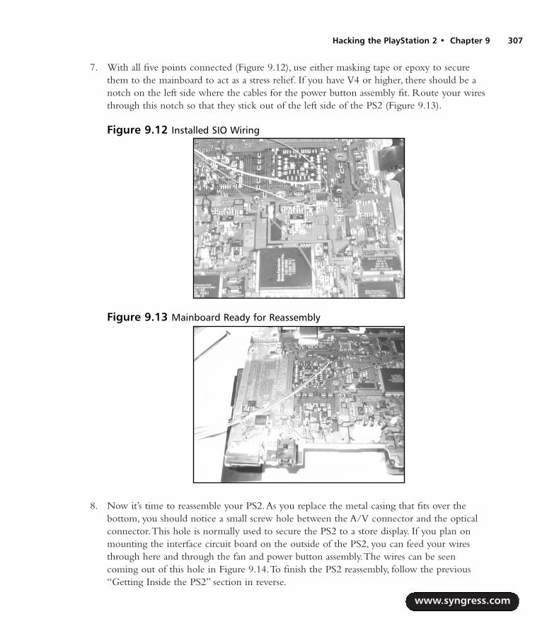
7. With all five points connected (Figure 9.12), use either masking tape or epoxy to securethem to the mainboard to act as a stress relief. If you have V4 or higher, there should be anotch on the left side where the cables for the power button assembly fit. Route your wiresthrough this notch so that they stick out of the left side of the PS2 (Figure 9.13).
8. Now it’s time to reassemble your PS2.As you replace the metal casing that fits over thebottom, you should notice a small screw hole between the A/V connector and the opticalconnector.This hole is normally used to secure the PS2 to a store display. If you plan onmounting the interface circuit board on the outside of the PS2, you can feed your wiresthrough here and through the fan and power button assembly.The wires can be seencoming out of this hole in Figure 9.14.To finish the PS2 reassembly, follow the previous“Getting Inside the PS2” section in reverse.
www.syngress.com
Hacking the PlayStation 2 • Chapter 9 307
Figure 9.12 Installed SIO Wiring
Figure 9.13 Mainboard Ready for Reassembly
287_HRD_HACK_09.qxd 1/14/04 1:44 PM Page 307

If you decide to use a five-pin plastic header, you should connect the wires to the female end atthis time. If you’re using a header, tape the wires together after fitting them or encase them in heat-shrink tubing. Figure 9.14 shows a 5-pin connection attached to the wires.
With all of the internal wiring completed, it’s time to build the external interface board.Theschematic is shown in Figure 9.15. On the DB9 connector of the PC serial cable, PC_RXD willconnect to pin 2, PC_TXD will connect to pin 3, and GND will connect to pin 5.
www.syngress.com
308 Chapter 9 • Hacking the PlayStation 2
Figure 9.14 The Completed Five-Wire SIO Connector
Figure 9.15 SIO Interface Schematic
MAX3323EEPE
C1+
C1-
C10.1µF
1
3
+3.3V
4
5
C20.1µF
SHDN RENABLE TXENABLE VCC
GND
C2+
C2-
VL
TIN1 TOUT1
ROUT1
V+
V-C30.1µF
C40.1µF
+1.7V (VCORE )
EE_TXD
EE_RXD
PC_RXD
2
6
7
9
10
1112
13
14
15
16
RIN1PC_TXD8
C50.1µF
287_HRD_HACK_09.qxd 1/14/04 1:44 PM Page 308

Because I used a five-pin plastic plug, I mounted the male end on one end of the board and thewires for the PC serial cable on the opposite end. For the serial cable itself, I took an unused DB9serial cable and cut off both ends. Next, I exposed enough of the wires to solder to the interfaceboard, and at the opposite end I attached PC_TXD, PC_RXD, and GND to a female DB9 connectorenclosed in a plastic hood. Figures 9.16 and 9.17 show the top and bottom of the completed board.
TestingTo test your interface board, connect the interface to the PC and connect the other end to the PS2.Using a terminal program (such as HyperTerminal which comes with Windows) set your serial portto 38400 baud, 8 data bits, no parity, 1 stop bit, and no hardware flow control. Power on your PS2. Ifthe cable is working properly, you should see messages similar to the ones in Figure 9.18.
www.syngress.com
Hacking the PlayStation 2 • Chapter 9 309
Figure 9.16 Top View of External SIO CableFigure 9.17 Bottom View of External SIOCable
Figure 9.18 EE Boot Messages
287_HRD_HACK_09.qxd 1/14/04 1:44 PM Page 309
Under the Hood: How the Hack WorksThis hack works by taking advantage of the undocumented SIO port of the PS2’s Emotion Engine(EE). Details of the SIO can be found in the “PS2 System Overview” section.A standard RS232 serialport in desktop PC’s generally use +/-12V to define a logic 0 (space) and logic 1 (mark).The EE ispowered using a +1.7V source, so if the SIO pins were connected directly to a PC serial port withoutany voltage conversion, the signals that the PC sent to the EE could possibly destroy the device.TheMAX3323 device is a “level shifter” which converts the voltage levels output by the EE to the levelsthe PC requires and vice versa.The +3.3V power source supplied by the PS2 is required to power theMAX3323.
Booting Code from the Memory CardOn August 15, 2003, I released the “Independence exploit” for the PS2 which enables the PS2 toboot any software stored on a standard PS2 memory card simply by launching a PS1 game.Any PS1game can be used as long as the game’s unique title ID has been written to the file on the memorycard that contains the exploit. When you power on the PS2 with a PS1 game already inserted intothe DVD drive, the exploit takes over as soon as the PS2 displays the Sony Computer Entertainmentbanner.The exploit can also be triggered by inserting a PS1 disc and launching the disc manuallyfrom the PS2’s browser.
NEED TO KNOW… PS2 INDEPENDENCE WEB SITE
The official Web site for the Independence exploit is www.0xd6.org/ps2-independence.html.Here you can find the latest version of the exploit and tutorial information about memorycard save files and setting up the exploit using Windows. Since the exploit’s release,numerous guides and tutorials have popped up on the Web detailing the steps to get var-ious pieces of homebrew software to run from the memory card. Some of this softwareincludes the Naplink USB boot loader (http://naplink.napalm-x.com), the Pukklink and ps2linkNetwork Adapter loaders (www.ps2dev.org, in the Loaders section), and the PS2Realitygroup’s MediaPlayer (www.ps2reality.net). Many more types of software are currently beingdeveloped, and using the exploit to load a boot loader has proven to be the easiest way toload custom software. Though the term “exploit” may sound nefarious, this discovery hasopened the doors to an entire community of homebrew programmers for the PS2.
Preparing for the HackThe most difficult part of this hack is finding a way to get the files onto a memory card. If your PS2is already modded or you use the “swap trick” to boot CDRs, you can use a disc image called ExploitInstaller written by Nicholas Van Veen.A tutorial for this installation is available http://ps2.consolevi-sion.com/ps2homebrew3.shtml.
www.syngress.com
310 Chapter 9 • Hacking the PlayStation 2
287_HRD_HACK_09.qxd 1/14/04 1:44 PM Page 310

NEED TO KNOW… THE RIGHT MEMORY CARD
The Independence exploit will only work with a Sony PS2 memory card or any third-partymemory card that supports MagicGate. It will not work with a PS1 memory card or withnon-MagicGate PS2 cards.
If you have no other method of loading a program on the PS2, you can buy one of severalmemory card adapters that connect to the PC via a USB cable. Doing a Web search for “USBmemory adapter” or “PS2 memory card adapter” will give you a bunch of places to buy one, or youcould visit www.lik-sang.com.
Performing the Hack: Preparing Title.DBIn order for the exploit to “trigger” off your PS1 game, you must add that game’s unique title ID tothe TITLE.DB file that is stored on the memory card. I’ve written a command-line utility calledtitleman to make it easier to do this.You can grab a Windows executable version of titleman from thetutorial section of the Independence Web site, or you can choose to compile it from source yourself.
NEED TO KNOW…I don’t know of any graphical utilities to manage the TITLE.DB file. You need to have somebasic familiarity with the text-based command line, which is sometimes called CommandPrompt in the Windows Start menu. It can be accessed by using Start | Run and typing ineither command or cmd and pressing Enter. If you are using a UNIX-based system(including Mac OS X), consult your system’s manual to find out how to access and use thecommand-line.
The titleman program options are listed in Table 9.4.The first step in creating a TITLE.DB file isto use the –c option.This creates TITLE.DB on disk and stores the exploit payload and a few standardtitle ID entries.
Table 9.4 The titleman Program Options
Option Description
-c Create a new TITLE.DB and initialize it-a Add one or more title IDs to TITLE.DB-d Delete one or more title IDs from TITLE.DB-l List all of the title IDs stored in TITLE.DB-o Specify an alternate output file-v Be verbose; output status messages
www.syngress.com
Hacking the PlayStation 2 • Chapter 9 311
287_HRD_HACK_09.qxd 1/14/04 1:44 PM Page 311
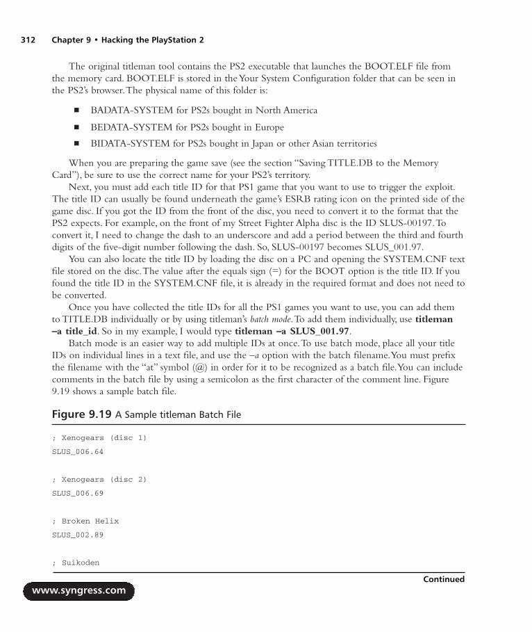
The original titleman tool contains the PS2 executable that launches the BOOT.ELF file fromthe memory card. BOOT.ELF is stored in the Your System Configuration folder that can be seen inthe PS2’s browser.The physical name of this folder is:
BADATA-SYSTEM for PS2s bought in North America
BEDATA-SYSTEM for PS2s bought in Europe
BIDATA-SYSTEM for PS2s bought in Japan or other Asian territories
When you are preparing the game save (see the section “Saving TITLE.DB to the MemoryCard”), be sure to use the correct name for your PS2’s territory.
Next, you must add each title ID for that PS1 game that you want to use to trigger the exploit.The title ID can usually be found underneath the game’s ESRB rating icon on the printed side of thegame disc. If you got the ID from the front of the disc, you need to convert it to the format that thePS2 expects. For example, on the front of my Street Fighter Alpha disc is the ID SLUS-00197.Toconvert it, I need to change the dash to an underscore and add a period between the third and fourthdigits of the five-digit number following the dash. So, SLUS-00197 becomes SLUS_001.97.
You can also locate the title ID by loading the disc on a PC and opening the SYSTEM.CNF textfile stored on the disc.The value after the equals sign (=) for the BOOT option is the title ID. If youfound the title ID in the SYSTEM.CNF file, it is already in the required format and does not need tobe converted.
Once you have collected the title IDs for all the PS1 games you want to use, you can add themto TITLE.DB individually or by using titleman’s batch mode.To add them individually, use titleman–a title_id. So in my example, I would type titleman –a SLUS_001.97.
Batch mode is an easier way to add multiple IDs at once.To use batch mode, place all your titleIDs on individual lines in a text file, and use the –a option with the batch filename.You must prefixthe filename with the “at” symbol (@) in order for it to be recognized as a batch file.You can includecomments in the batch file by using a semicolon as the first character of the comment line. Figure9.19 shows a sample batch file.
Figure 9.19 A Sample titleman Batch File
; Xenogears (disc 1)
SLUS_006.64
; Xenogears (disc 2)
SLUS_006.69
; Broken Helix
SLUS_002.89
; Suikoden
www.syngress.com
312 Chapter 9 • Hacking the PlayStation 2
Continued
287_HRD_HACK_09.qxd 1/14/04 1:44 PM Page 312

Figure 9.19 A Sample titleman Batch File
SLUS_002.92
; Suikoden II
SLUS_009.58
; Sentient
SCUS_941.10
; Blood Omen: Legacy of Kain
SLUS_000.27
The full listing of the steps required to add a single title (Street Fighter Alpha) are given in Figure 9.20.
Figure 9.20 All steps to create and add an entry to TITLE.DB
$ titleman –c
$ titleman –a SLUS_001.97
If you make a mistake while adding a title ID or if you want to remove an ID you’ve alreadyadded, use titleman’s –d option.You can delete individual IDs the same way you added them, or youcan use batch mode.
If you need to check which IDs you’ve already added to TITLE.DB, use the –l option.
Choosing BOOT.ELFVersion 0.1 of the exploit loads the executable file BOOT.ELF from the memory card after the exploithas taken over. BOOT.ELF is stored in the same folder as TITLE.DB. If you want to start developingyour own software for the PS2, the best choice for BOOT.ELF is ps2link, an Open Source boot loaderfor loading programs via the official PS2 Network Adapter.The latest version of ps2link is available atwww.thethirdcreation.net/tools, or from www.ps2dev.org (in the Loaders section).
If you are interested in streaming movies, MP3s, and Ogg Vorbis files over the network, you willwant to install PS2Reality’s MediaPlayer.You’ll find tutorials for using the MediaPlayer with theexploit at www.ps2reality.net. (Warning: the site is in Spanish!)
Finally, if you want to fire up some of your old Sega Genesis games, Nicholas Van Veen’s PGENGenesis emulator also works well with the exploit.You can download PGEN from http://pgen.game-base.ca.
To use any of the previous programs with the exploit, they must be setup properly so that theyare loaded as soon as the exploit takes over. Some programs contain specific instructions in theREADME file shipped with the program. Failing that, you can try renaming the programs main .ELFto BOOT.ELF (for example, rename PGEN_11.ELF to BOOT.ELF).
www.syngress.com
Hacking the PlayStation 2 • Chapter 9 313
287_HRD_HACK_09.qxd 1/14/04 1:44 PM Page 313
Saving TITLE.DB to the Memory CardNow that we’ve created TITLE.DB listing all of the game titles that we want to trigger the exploit with,we need to find a way to get the file onto the memory card.There are several ways of doing this:
Using Nicholas Van Veen’s Exploit Installer This method either requires your PS2 tohave a modchip installed or you must be willing to perform the swap trick.Although thismethod is convenient, I don’t recommend swapping, since it is potentially damaging to yourPS2 (or requires a hardware modification).You can grab the Exploit Installer fromwww.ps2newz.net/forums/showthread.php?threadid=14803
Using a commercial USB memory card adapter Memory card adapters allow you totransfer “game saves” directly to a memory card inserted into the adapter and connected toyour PC.To use this method, you must either create a brand-new game save using the name“Your System Configuration” and the save folder for your PS2’s territory, or you can openan existing save and rename it. Once you have created your save, copy TITLE.DB andBOOT.ELF into it. Make sure that both the TITLE.DB and BOOT.ELF filenames are in allcapitals or the exploit won’t work. Once you have created this save, transfer it to yourmemory card using the software provided with your adapter.
The nPort utility Napalm, the development team that wrote the Naplink USB bootloader, also developed a utility called nPort for transferring game saves between the PC andPS2 using an existing USB connection (in Naplink) or by using the official network adapter(in Pukklink or ps2link).The PS2 Independence Web site provides an .npo file (the formatexpected by nPort) that contains all the required export files.The site also features a tutorialthat provides details on how to use nPort to save the exploit.You can find nPort athttp://wire.napalm-x.com.
Independence!Once you’ve saved the exploit to the memory card, insert the card into the PS2 and pop in any oneof your PS1 games that you’ve added to the title ID list.After the disc loads, you should see a briefwhite flash followed by the initial screen of your BOOT.ELF program. If the game you insert goesinto the normal PS1 emulator, recheck your TITLE.DB contents using the –l option and make sureyou spelled the title ID correctly.Also verify that you have the correct PS1 game inserted. If you get ared screen while loading the exploit, make sure that you have BOOT.ELF in the same folder asTITLE.DB.Any other errors that you notice will be specific to the application that you chose asBOOT.ELF.
Under the Hood: How the Hack WorksThe PS2 is able to emulate PS1 software through a combination of hardware emulation and a soft-ware PS1 graphics emulator called PS1DRV. Whenever you boot a PS1 game on your PS2, the systembrowser first loads and executes PS1DRV from the BIOS. PS1DRV performs a number of configura-
www.syngress.com
314 Chapter 9 • Hacking the PlayStation 2
287_HRD_HACK_09.qxd 1/14/04 1:44 PM Page 314

tion steps such as setting the disc speed and reading specific graphic parameters for the selected game.Finally, it initializes the graphics emulator and reboots the IOP into PS1 mode. Now the IOP takesover, and the PS1 game is loaded from disc. Graphics are emulated using a special SIF DMA channelfrom the IOP to PS1DRV on the EE.
When a PS1 disc is inserted into the PS2, the system browser reads the disc’s title ID from a fileon disc called SYSTEM.CNF. SYSTEM.CNF also contains other PS1 boot parameters such as thedefault video mode that the game was written to use.The game’s title ID is passed along to PS1DRVso that PS1DRV can select parameters for its graphics emulator tuned to each individual game. If thesystem browser can’t find SYSTEM.CNF on the PS1 disc, the value ‘???’ is passed to PS1DRV instead.
When PS1DRV looks for game-specific parameters for its graphics emulator, it searches threelocations: a built-in table, SYSTEM.CNF on disc, and a file on a memory card called TITLE.DB.TheTITLE.DB file is stored in a system folder reserved for BIOS programs. If the PS2’s region of sale isJapan or Asia, this folder is called BIDATA-SYSTEM; if the region is Europe, it’s called BEDATA-SYSTEM; and if the region is North America, it’s called BADATA-SYSTEM.
I found the Independence exploit within the routines that parse the title ID out of TITLE.DB.Amain TITLE.DB loading routine that I’ll call load_mc_title.db() is responsible for loading theTITLE.DB from the memory card into RAM. It calls another routine, find_title_params(), to locatethe title ID within the loaded TITLE.DB and return a string value containing its parameter values. It’sinteresting to note that the way TITLE.DB is loaded into RAM makes the exploit extremely easy toimplement.TITLE.DB is loaded to the fixed RAM address 0x20800000, and the entire contents ofthe file are loaded.This means that we can include an entire program to take over after the exploitinside TITLE.DB and know exactly where it loads!
The find_title_params() routine is passed three parameters: the address where TITLE.DB is loaded(title_db), the address of a string variable to receive the parameter values (params), and the title ID tosearch for (title_name). It executes a loop to search each line (a line is terminated by an ASCII linefeed, carriage return, or both) for the title ID. If it finds the title ID, it scans the rest of the line fol-lowing the title ID and an equals sign to look for the terminating characters. Once those are found, itcopies this string into the params string value.This copying is where the exploit occurs.
Ideally the parameter value associated with a title ID would be around 25 bytes, including theterminating line feed. In the load_mc_title_db() routine, Sony allocates 256 bytes to store this value, andthese bytes are stored in RAM next to a very important EE register, the return address or $ra register.On the MIPS architecture, when a routine executes another routine, it saves $ra to RAM because theCPU automatically updates $ra to point to the last instruction of the calling routine. Once the calledroutine has finished executing, $ra still points to this instruction, so when the caller itself prepares toexit, it must first restore $ra from RAM. In the load_mc_title_db() routine, the $ra that is saved beforecalling find_title_params() is located after the space allocated to store the params string value.
When find_title_params() copies the parameter string into params, it uses the C function strcpy(),which copies one string of arbitrary length over another string.The strcpy() function has no boundarychecking, so it will copy the entire string until it finds the terminating NUL (ASCII 0) character.Thismeans that if we were to construct a string inside TITLE.DB that is longer than the 256 bytes allo-cated for params, we could overwrite the saved $ra register (since it is stored in RAM after the paramsvalue). Whatever value that $ra is overwritten with becomes the next address executed afterload_mc_title_db() exits, and this can be any RAM address that is accessible by the EE.
www.syngress.com
Hacking the PlayStation 2 • Chapter 9 315
287_HRD_HACK_09.qxd 1/14/04 1:44 PM Page 315

This type of exploit, called a buffer overflow, is commonly found in software for which there is noboundary checking on strings or other values loaded from data files. It is easily preventable, as is thecase with the Independence exploit in PS1DRV. Using the standard C function strncpy(), you canenforce the maximum length of the copied string. If Sony had originally used strncpy() with a max-imum length of 256, the exploit would’ve never been possible.
So once we construct this string inside TITLE.DB, where do we point $ra? Remember thatload_mc_title_db() loads the entire contents of TITLE.DB into RAM, at the fixed address 0x20800000.We can point $ra to any address after TITLE.DB’s load address. In the Independence exploit, I usedthe fixed address 0x20810110, to allow enough room for approximately 200 entries in TITLE.DB.When load_mc_title_db() exits, $ra points to this address, and my code assumes control of the PS2.
Other Hacks: Independent Hard DrivesWith the launch of Sony’s PlayStation 2 Linux Kit (released in May 2002) and the official NetworkAdapter (released in August 2002), PS2s have gained an often overlooked addition: hard disk drive(HDD) support. In addition to the official Sony HDD that shipped with the Linux Kit, PS2 owners canalso use off-the-shelf HDDs that fit the IDE connectors on the network adapter.While Sony’s officialHDD for consumers (i.e. those people who didn’t buy the Linux Kit) is expected to be released inMarch 2004, homebrew software is already being written to take advantage of existing HDDs.
In November 2003, Nicholas Van Veen, along with others including myself, developed andreleased libHDD, a set of libraries and drivers for homebrew software to access the HDD. libHDDalso includes support for Sony’s official file system layout to be used by games that access the HDD.libHDD is available for download at http://ps2dev.org/kb.x?T=967. Using libHDD, programsdesigned to run from the memory card can access data or even other programs stored on the HDD.This opens up a range of potential projects, from emulators that support loading ROMs from theHDD (PGEN already does) to media players that play audio and video saved to the HDD. Hopefully,as more homebrew developers release HDD-aware programs, the PS2 will gain more recognition as aconsumer hardware hacking platform.
PS2 System OverviewThe PS2 is built on a parallel architecture—it achieves high performance by splitting program tasksamong multiple processors and coprocessors.A typical PS2 game will decide logic and game flow onthe main processor, handle user input and audio on an auxiliary (or sub) processor, and transform 3Dgeometry on one of two high-speed coprocessors. Contrast this to the traditional PC-based architec-ture, where only a single processor is dedicated to user input, game logic, and graphics output. Ofcourse, modern 3D graphics cards now come equipped with a high-speed programmable graphicsprocessing unit (GPU) that can offload 3D lighting and vertex calculations from the main CPU ontothe graphics card.
www.syngress.com
316 Chapter 9 • Hacking the PlayStation 2
287_HRD_HACK_09.qxd 1/14/04 1:44 PM Page 316

Understanding the Emotion EngineThe heart of the PS2 is a 64-bit Toshiba MIPS processor dubbed the Emotion Engine, or EE (Figure9.21).The EE is the predecessor of ArTile Micro’s TX79 line of System-on-a-Chip (SoC) processors.A SoC design is one in which all the external peripherals required to manage the system are inte-grated onto a single chip. For example, a common TX79 chip, the TMPR7901, integrates the MIPSCPU core, an SDRAM memory controller, a PCI bus controller, and an Ethernet controller, amongother peripherals.The main benefits of SoC processors are reduced manufacturing costs and betterperformance between the integrated peripherals. SoC designs usually contain one or more high-speedinternal buses that interface with external peripherals using a slower, shared system bus.
The EE includes the following documented on-chip peripherals:
MIPS R5900 CPU core
Two vector processing units (VUs or VPUs)
Floating point unit (FPU)
DMA controller (DMAC)
Interrupt controller (INTC)
Programmable timers
Sub-CPU interface (SIF)
Two VU interfaces (VIFs)
Graphics Synthesizer (GS) interface (GIF)
Image processing unit (IPU)
www.syngress.com
Hacking the PlayStation 2 • Chapter 9 317
Figure 9.21 The Emotion Engine
287_HRD_HACK_09.qxd 1/14/04 1:44 PM Page 317

It also includes the following undocumented peripherals:
RDRAM controller [(R)DRAMC]
Serial I/O port (SIO; UART)
JTAG (IEEE 1149.1) Boundary-Scan interface
NEED TO KNOW… DIVINING DOCUMENTATION
A detailed examination of all the EE’s integrated peripherals would fill several chapters. Thehardware manuals shipped on Disc 1 on the PlayStation 2 Linux Kit (www.playstation2-linux.com) provide an invaluable resource to the inner workings of the PS2’s Emotion Engineand Graphics Synthesizer. If you do not own the kit, you can find basic information on theEmotion Engine’s CPU core in the hardware manuals for the EE’s descendant, the TX79 pro-cessor, which can be found at www.semicon.toshiba.co.jp/eng/index.html. You can find tuto-rials on programming the PS2 at www.ps2dev.org and www.oopo.net/consoledev.
The Serial I/O PortThe SIO implements a high-speed UART with an 8-byte transmit first in, first out (FIFO) and 16-byte receive FIFO. It also includes the common CTS and RTS signals for hardware-based flow con-trol.Although the SIO-related pins are unconnected in consumer PS2s, the EE’s BIOS and runtimekernel use the SIO to output status messages during the PS2 boot process.
The SIO isn’t documented in the EE User’s Manual, so I had a look in the PS2’s BIOS for theinitialization and character output code. I also found a wealth of information on the SIO interruptand hardware registers in the Toshiba TX79 Core Architecture Manual, the TMPR7901 hardwaremanual, and the TMPR4925 hardware manual. It turns out that the TX79 Core Architecture Manualis nearly identical to Sony’s EE Core User’s Manual, except that all SIO-related documentation wasremoved from the latter.
After studying the BIOS and kernel SIO code, the available documentation, and writing a fewtest programs, I was able to assemble a reasonably accurate list of registers and definitions.The EE’sSIO shares most of its registers with the TX49 implementation, but I couldn’t find any indication thatDMA was supported. It also shares a few register definitions with the TX7901’s UARTs.Table 9.5shows the SIO register map.
www.syngress.com
318 Chapter 9 • Hacking the PlayStation 2
287_HRD_HACK_09.qxd 1/14/04 1:44 PM Page 318

Table 9.5 The SIO Register Map
Address Name Description
0x1000f100 SIO_LCR Line control register0x1000f110 SIO_LSR Line status register0x1000f120 SIO_IER Interrupt enable register0x1000f130 SIO_ISR Interrupt status register0x1000f140 SIO_FCR FIFO control register0x1000f150 SIO_BGR Baud rate control register0x1000f180 SIO_TXFIFO Transmit FIFO register0x1000f1c0 SIO_RXFIFO Receive FIFO register
Using the TX79 manual, I found that when the SIO needs to interrupt the CPU, it triggers aDebug exception and sets bit 12 of the COP0 cause register.The CPU then decodes the SIO inter-rupt status register to determine the cause of the interrupt.The EE kernel uses the SIO exception as ameans to start the kernel’s built-in debugger.
To initialize the SIO, you first write a value to SIO_LCR indicating the number of data bits and stopbits and whether to enable parity checking.You can also specify where the baud rate generator will getthe clock source used to determine the baud rate.The next step is to reset both FIFOs and to optionallyenable any interrupts. Finally, you need to calculate the divisor and the clock value used to maintain thebaud rate.The code in Figure 9.22 is an example of how to initialize the SIO with the specified baudrate, using the standard transmission parameters of 8N1 (8 data bits, no parity checking, 1 stop bit).
Figure 9.22 SIO Initialization Code Example
#define SIO_FCR_FRSTE 0x01 /* FIFO Reset Enable. */
#define SIO_FCR_RFRST 0x02 /* RX FIFO Reset. */
#define SIO_FCR_TFRST 0x04 /* TX FIFO Reset. */
#define CPUCLK 294912000 /* Used to determine the baud divide value. */
void sio_init(u32 baudrate)
u32 brd; /* Baud rate divisor. */
u8 bclk = 0; /* Baud rate generator clock. */
/* 8 data bits, 1 stop bit, no parity checking, and use the CPU
clock for determining the baud rate. */
_sw((1<<5), SIO_LCR);
www.syngress.com
Hacking the PlayStation 2 • Chapter 9 319
Continued
287_HRD_HACK_09.qxd 1/14/04 1:44 PM Page 319

Figure 9.22 SIO Initialization Code Example
/* Disable all interrupts. */
_sw(0, SIO_IER);
/* Reset the FIFOs. */
_sw(SIO_FCR_FRSTE|SIO_FCR_RFRST|SIO_FCR_TFRST, SIO_FCR);
/* Enable them. */
_sw(0, SIO_FCR);
brd = CPUCLK / (baudrate * 256);
while ((brd >= 256) && (++bclk < 4))
brd /= 4;
_sw((bclk << 8) | brd, SIO_BGR);
Character input and output are straightforward:You write to SIO_TXFIFO to output a characterand read from SIO_RXFIFO on input.You’ll need to check SIO_ISR to make sure that either theTX FIFO has room for another character or that the RX FIFO has at least one character ready to beread.The code in Figure 9.23, modeled after the ANSI Standard C Library putc() and getc() functions,demonstrates how to do this.
Figure 9.23 SIO Input/Output Code Example
int sio_putc(int c)
/* Block until we're ready to transmit. */
while ((_lw(SIO_ISR) & 0xf000) == 0x8000);
_sb(c, SIO_TXFIFO);
return c;
int sio_getc()
/* Do we have something in the RX FIFO? */
if (_lw(SIO_ISR) & 0xf00)
return _lb(SIO_RXFIFO);
www.syngress.com
320 Chapter 9 • Hacking the PlayStation 2
Continued
287_HRD_HACK_09.qxd 1/14/04 1:44 PM Page 320

Figure 9.23 SIO Input/Output Code Example
/* Return EOF. */
return -1;
The I/O ProcessorThe I/O processor, or IOP, manages most of the on-board and external peripherals includingmemory cards, the sound processing unit (SPU), controller pads, and the DVD drive. It is a SoCdesign from LSI Logic based on the original PlayStation (PS1), and it includes all the PS1’s mainfunctions on a single chip.The core of the IOP is a MIPS R3000A CPU running at 36.864MHz(native speed).The IOP’s native speed is approximately 1/8th the speed of the EE, which runs at294.9Mhz. When emulating PS1 hardware, the IOP runs at the PS1’s original speed of 33MHz.TheIOP can directly access 2MB of RAM. It communicates with internal devices and external periph-erals via the SBUS.
The Sub-CPU InterfaceThe IOP is also referred to as the sub-CPU, with the EE being the main CPU.The sub-CPUInterface, or SIF, is a high-speed DMA connection between the IOP and EE. Using the SIF, each pro-cessor can transfer data directly into the other processor’s RAM.The most common use of the SIF isa Remote Procedure Call (RPC) interface that allows the EE to call routines on the IOP.These rou-tines access the low-level hardware driver corresponding to the RPC and return data via the SIF backto the EE. In this way, the EE can request to read from a file on an inserted DVD, continue its pro-cessing, and be interrupted by the IOP after the read request is complete.Also, using the SIF, the IOPcan schedule controller data to be sent to a buffer on the EE on every Vblank (“vertical blank”, 1/60th
of a second for NTSC machines, or approximately one frame of video).The EE can access this datawithout having to make an explicit request for it every single frame.
Additional Web Resources Official ps2dev home: www.ps2dev.org Contains tutorials, code, boot loaders, and
many other resources to get you started writing homebrew software for the PS2.
The Third Creation: www.thethirdcreation.net The home of monthly PS2 democompetition. Many amazing demos are hosted here, all written using Open Source software.
www.syngress.com
Hacking the PlayStation 2 • Chapter 9 321
287_HRD_HACK_09.qxd 1/14/04 1:44 PM Page 321

I’d highly recommend that you download any demos authored by adresd; these are amongthe best.
PlayStation 2 Linux Kit: www.playstation2-linux.com Sony’s official home of thePlayStation 2 Linux Kit, a hardware and software development kit that allows you to runLinux on the PS2.
Dan Peori’s Web site: www.oopo.net/consoledev Code and tutorials ranging fromgraphics to the SIF.
Lukasz Brunn’s Mouthshut: www.mouthshut.net The home of libITO, one of thefirst graphics libraries written for PS2 homebrew.
www.syngress.com
322 Chapter 9 • Hacking the PlayStation 2
287_HRD_HACK_09.qxd 1/14/04 1:44 PM Page 322

Wireless 802.11 Hacks
Hacks in this Chapter:
Wireless NIC/PCMCIA Card Modifications:Adding an External Antenna Connector
Open AP (Instant802): Reprogramming YourAccess Point with Linux
Having Fun with the Dell 1184 Access Point
Additional Resources and Other Hacks
Chapter 10
323
287_HRD_HACK_10.qxd 1/13/04 7:41 PM Page 323
IntroductionHacking wireless hardware is an endeavor steeped in a rich history of experimentation and hobbyistculture.The wireless hardware hacker of today pursues his or her craft with a passion not seen sincethe amateur radio (also known as “ham radio” or “hams”) operators of the last generation. Manywireless enthusiasts are, in fact, connected with the ham community. Once solely the domain of asmall group of Radio Frequency (RF) engineers, wireless gear has never been so inexpensive andaccessible as it is today. With rapidly declining hardware costs, anybody can learn and experiment with802.11 equipment with only a small investment.
In this chapter, we review several wireless hacks, tricks, and hardware modifications, including:
D-Link DWL650 Card modification for adding an external antenna.
OpenAP (Instant802) Reprogramming your Access Point (AP) to run an open-sourceversion of Linux.
Dell 1184 Access Point Exploring the embedded Linux operating system.
WARNING: PERSONAL INJURY
Please use extreme care when performing any kind of experimentation with RF devices. Formore information about the dangers of RF exposure, visit the following URLs:
www.wlana.org/learn/health.htm www.arrl.org/tis/info/rfexpose.html
NEED TO KNOW…802.11 is a protocol created by the Institute of Electrical and Electronics Engineers (IEEE).This protocol defines a method for transmitting and receiving data communications wire-lessly. The original specification was ratified in 1997. This protocol supported 3 physicalmethods: Frequency Hopping Spread Spectrum (FHSS) and Direct Sequence Spread Spectrum(DSSS) in the 2.4GHz frequency range, as well as Infrared (IR). (Note that IR was never suc-cessfully deployed as a commercial option). Speeds of 1Mbps and 2Mbps were supported. In1999, the IEEE approved 2 new higher speed additions to the protocol: 802.11a and802.11b. 802.11a defined (up to) 54Mbps Orthogonal Frequency Division Multiplexing(OFDM) at 5GHz and 802.11b defined 5.5Mbps and 11Mbps using DSSS in the 2.4GHz spec-trum. In 2003, 802.11g was established to provide (up to) 54Mbps OFDM in the 2.4GHzspectrum. For more information about the 802.11 protocol, please visithttp://grouper.ieee.org/groups/802/11/.
www.syngress.com
324 Chapter 10 • Wireless 802.11 Hacks
287_HRD_HACK_10.qxd 1/13/04 7:41 PM Page 324
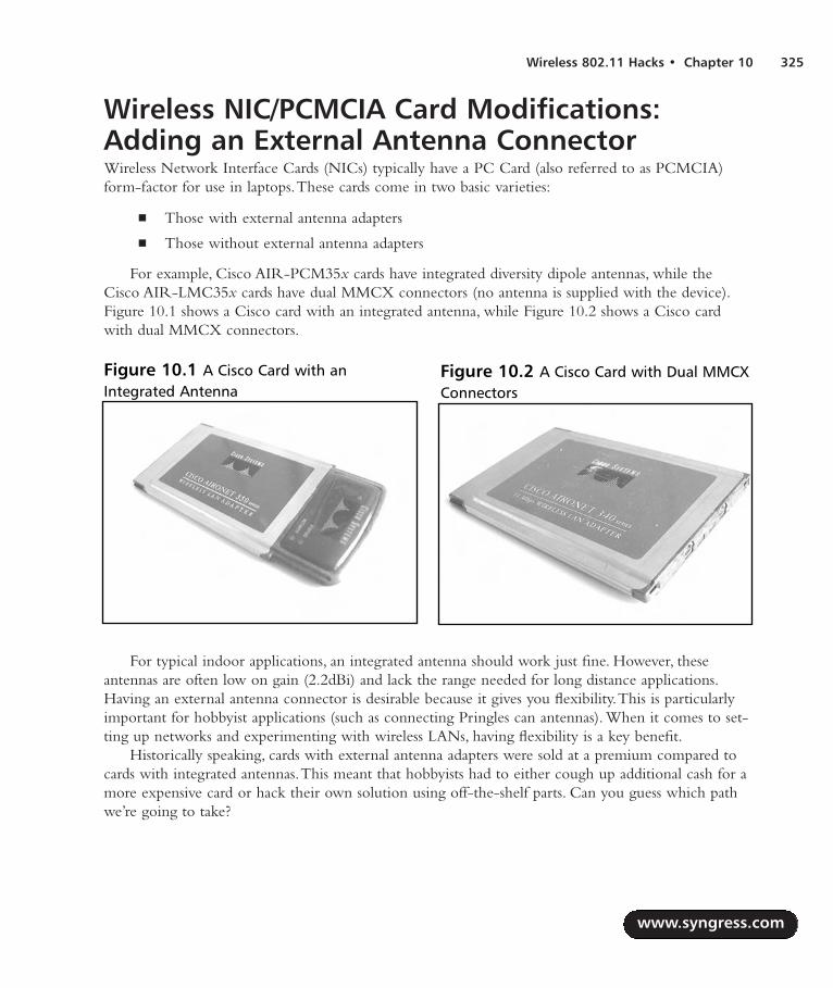
Wireless 802.11 Hacks • Chapter 10 325
Wireless NIC/PCMCIA Card Modifications:Adding an External Antenna ConnectorWireless Network Interface Cards (NICs) typically have a PC Card (also referred to as PCMCIA)form-factor for use in laptops.These cards come in two basic varieties:
Those with external antenna adapters
Those without external antenna adapters
For example, Cisco AIR-PCM35x cards have integrated diversity dipole antennas, while theCisco AIR-LMC35x cards have dual MMCX connectors (no antenna is supplied with the device).Figure 10.1 shows a Cisco card with an integrated antenna, while Figure 10.2 shows a Cisco cardwith dual MMCX connectors.
For typical indoor applications, an integrated antenna should work just fine. However, theseantennas are often low on gain (2.2dBi) and lack the range needed for long distance applications.Having an external antenna connector is desirable because it gives you flexibility.This is particularlyimportant for hobbyist applications (such as connecting Pringles can antennas). When it comes to set-ting up networks and experimenting with wireless LANs, having flexibility is a key benefit.
Historically speaking, cards with external antenna adapters were sold at a premium compared tocards with integrated antennas.This meant that hobbyists had to either cough up additional cash for amore expensive card or hack their own solution using off-the-shelf parts. Can you guess which pathwe’re going to take?
www.syngress.com
Figure 10.1 A Cisco Card with anIntegrated Antenna
Figure 10.2 A Cisco Card with Dual MMCXConnectors
287_HRD_HACK_10.qxd 1/13/04 7:41 PM Page 325

Preparing for the HackIn this hack, we will be modifying a D-Link DWL-650. Note that a number of variations exist forthe D-Link 650 card so ensure you obtain a standard 16-bit PCMCIA PC Card by comparing yourcard to the one in Figure 10.3.This is important because D-Link sold 32-bit CardBus NICs for ashort time and called them D-Link 650! So really, the only way to be absolutely certain that the cardyou have on hand is the correct one for this hack is to look at the card…
The items you will need for this hack are:
D-Link DWL-650 Wireless NIC An inexpensive PCMCIA card that lacks an externalantenna.
BNC cable A small length of Thinnet cable connected to a BNC connector.
Soldering iron To solder the connector wires to the leads on the Printed Circuit Board(PCB).
X-ACTO knife To create a hole in the plastic casing for the wiring.
Tweezers or a toothpick To open the casing and gain access to the PCB.
WARNING: HARDWARE HARM
This hardware modification will void your warranty and potentially violate FCC regulations.This hack should be used for test purposes only and not in a production environment.
www.syngress.com
326 Chapter 10 • Wireless 802.11 Hacks
Figure 10.3 An Unmodified D-Link DWL-650 Card
287_HRD_HACK_10.qxd 1/13/04 7:41 PM Page 326

Wireless 802.11 Hacks • Chapter 10 327
You can choose from a variety of cable connectors for attaching your card to an external antenna.Some vendors have proprietary connectors, such as the Cisco MMCX connector. Other connectorsare industry standard, such as BNC and N. In our hack, we will use a BNC connector. Don’t worry ifyour antenna uses something other than BNC, because adapters to convert BNC to pretty much anykind of connector are easily available and inexpensive. For more information about RF Connectors,the following Web sites are useful:
www.rfconnector.com
www.therfc.com
Furthermore, it’s fairly uncomplicated to find a BNC plug with a short length of cable, since youcan simply take any old BNC Thinnet cable and snip off the connector (saving a few inches of cable).Figure 10.4 shows an unmodified Thinnet cable.
Performing the HackHacking the DWL-650 to add external antenna functionality is performed in three basic steps:
1. Removing the cover.
2. Desoldering a capacitor and soldering it to an adjacent spot on the PCB.
3. Soldering the BNC connector’s leads to the PCB.
Removing the CoverThe first step is to open the top cover of the D-Link DWL-650 card and expose the internalantennas.To do this, turn the card upside down (with the MAC address label facing you) and get yourtweezers handy. On the short gray tab (protruding from the silver PCMCIA card), you will see foursmall clasps that hold the plastic cover in place as denoted in Figure 10.5. Each clasp contains two
www.syngress.com
Figure 10.4 An Unmodified Thinnet Cable
287_HRD_HACK_10.qxd 1/13/04 7:41 PM Page 327

semicircular plastic posts. Use your tweezers to squeeze the semicircular plastic posts together.Youmight also use a small flat-head screwdriver to wedge the gray plastic pieces apart as you advance toeach plastic post. If you don’t have tweezers, a toothpick can be wedged into the outer circle and usedto leverage the semicircle posts toward each other.
Once the posts are sufficiently squeezed together, you can then slowly and gently pry the graycover off. Note that the cover is held in place by two gray tabs tucked neatly into the silver PCMCIAcard edges.You may need to use a small flat-head screwdriver to carefully pry the silver chassis openjust wide enough to slide out one end of the gray tabs. Be particularly careful here, since it’s nearlyimpossible to fix the edges of the silver chassis once they are bent by mistake. Figure 10.6 shows thecover once it’s been removed.
After exposing the antenna compartment (Figure 10.7), you should see some silk-screened labelsnext to two surface-mount capacitors (C144 and C145).These capacitors are connected to the card’sdual internal antennas.You will also notice a silk-screened label for ANT3.That’s right—it seems as if
www.syngress.com
328 Chapter 10 • Wireless 802.11 Hacks
Figure 10.5 The Semicircular Posts Holding the Card Together
Figure 10.6 The Gray Cover
287_HRD_HACK_10.qxd 1/13/04 7:41 PM Page 328

the D-Link card was actually designed to have a third, external antenna. However, it was never imple-mented and this connector lays dormant—until now!
Moving back to your gray casing and the gray cover you just removed, you will need to bore outa small hole to make room for the BNC cable to pass through.Take your X-ACTO knife and care-fully scrape out a small hole in both the top and bottom portions of the gray casing as shown inFigure 10.8. Note that this task is best performed by first removing the gray cover (as described in theprevious step) and then separately boring out a semicircle in each half of the gray casing.
Moving the Capacitor The second step of the hack is to desolder one of the surface-mount capacitors, either C144 or C145.It doesn’t really matter which one you choose to remove. Once the capacitor has been removed, youneed to resolder it to the lead labeled ANT3.You can do this by rotating the capacitor 90 degrees. If
www.syngress.com
Wireless 802.11 Hacks • Chapter 10 329
Figure 10.7 Inside the Antenna Compartment
Figure 10.8 Making a Hole in the Gray Casing
287_HRD_HACK_10.qxd 1/13/04 7:41 PM Page 329

you chose C145, you will need to rotate the capacitor 90 degrees clockwise. If you chose C144, youwill need to rotate the capacitor 90 degrees counterclockwise. In effect, all you are doing is discon-necting one of the surface-mount antennas (the thin diamond-looking leads on the PCB) and electri-cally connecting it to the ANT3 leads. Figure 10.9 shows a close-up of the antenna compartmentbefore the hack.
WARNING: HARDWARE HARM
Be very careful when applying heat to the circuit board with your soldering iron. Too muchheat may damage the capacitors or the board and may cause the pads and traces to lift up,causing irreparable damage. In practice, it helps to use the tweezers to hold the capacitor inplace in the new location while you carefully apply the solder. Sometimes it helps to have asecond person involved to lend a hand with the tricky procedure.
www.syngress.com
330 Chapter 10 • Wireless 802.11 Hacks
Figure 10.9 Antenna Compartment: Close-Up Before the Hack
287_HRD_HACK_10.qxd 1/13/04 7:42 PM Page 330

Attaching the New ConnectorThe final step in the D-Link hack is to connect your BNC adapter to the PCB. Prepare your con-nector by removing the plastic covering and shielding to expose the center conductor and the sur-rounding copper strands. Figure 10.10 shows a prepared BNC connector.
The BNC connector should be soldered to the PCB at the gold-colored leads near the top of theantenna compartment.The center conductor of the BNC connector needs to be soldered to thecenter lead of ANT3, while the outer strands should be soldered to the adjacent pads on the PCB.
Once the soldering is complete, you can reattach the gray plastic cover by sliding in one of thelittle tabs and wedging the rest of the cover back in place.You should be able to snap it back togetherwith ease. If there is too much resistance, go back and get your X-ACTO knife to widen the hole foryour BNC cable a little more.Your completed hack should resemble the image in Figure 10.11.
Remember to be very gentle with your new external BNC cable, because the force of insertingand removing antennas may cause the solder connections to come loose from the internal PCB. Manyhobbyists have resorted to applying electrical tape or other reinforcing methods to keep the cable inplace and protect the connections from getting damaged. One popular method is to use a hot-gluegun to apply glue to the cable and the surrounding gray casing.
www.syngress.com
Wireless 802.11 Hacks • Chapter 10 331
Figure 10.10 A Prepared BNC Connector Ready for the Hack
287_HRD_HACK_10.qxd 1/13/04 7:42 PM Page 331

Under the Hood: How the Hack WorksThis D-Link hack is a simple example of how you can gain additional functionality from a productthat has been intentionally unused by its vendor. It is clear from the PCB design that this NIC wasoriginally intended to support an external antenna (as seen by the ANT-3 pads on the PCB), but itwas never implemented. Moving the capacitor simply disables part of the internal antenna circuitryand makes the signal available to an external connection. Note that your card will still work even ifyou don’t attach an external antenna, because diversity mode will allow the still-connected secondantenna (on the PCB) to transmit and receive a useable signal.
Diversity mode works by monitoring each antenna and automatically switching to the antennawith the stronger signal.This mode helps reduce errors caused by multipath problems. Multipatherrors occur when signals bounce off objects in the transmission path and the same signal arrives atthe receiver two times.
OpenAP (Instant802): Reprogramming Your Access Point with LinuxWireless Internet access using standard off-the-shelf APs is lots of fun. However, traditional consumer-grade APs can be quite feature limited. Sure, it’s possible to take an old PC, run Linux, and build yourown AP, but the hardware form factors for old PCs tend to be large, clunky, and noisy. With a smallform factor, you can install your AP in hard-to-reach places, weatherproof boxes, or tucked away in acorner. Wouldn’t it be cool if we could take an off-the-shelf AP and reprogram it with a Linux oper-ating system? That’s what you can do with OpenAP, a free software package from Instant802(http://opensource.instant802.com).
www.syngress.com
332 Chapter 10 • Wireless 802.11 Hacks
Figure 10.11 The Finished Hack: D-Link DWL-650 with External Antenna Connector
287_HRD_HACK_10.qxd 1/13/04 7:42 PM Page 332

NOTE
If you are unfamiliar with Linux, we suggest you refer to Chapter 14, “Operating SystemsOverview,” and Chapter 15, “Coding 101,” to brush up on your skills before moving on tothis hack.
Preparing for the HackOpenAP is a completely free and open-source software package. However, it works only with certainhardware devices. Specifically, you need an AP that is based on an Eumitcom WL11000SA-N chipset.The good news is that these can be found in a number of consumer-grade APs, including:
U.S. Robotics USR 2450 (Figure 10.12)
SMC EZConnect 2652W
Addtron AWS-100
Netcomm NP2000AP
These devices can often be found at aftermarket resellers and on eBay and other online sources.Along with the appropriate AP, you also need the following items:
Linearly-mapped external memory card This card needs to be 2MB (minimum) andoperate at 3.3 volts.The OpenAP Web site (http://opensource.instant802.com) recommendsa MagicRAM Industrial SRAM Memory Card.Another option for the memory card is thePretec FA2002.
www.syngress.com
Wireless 802.11 Hacks • Chapter 10 333
Figure 10.12 The U.S. Robotics USR 2450
287_HRD_HACK_10.qxd 1/13/04 7:42 PM Page 333

Null modem cable This is the cable you will need to connect your AP to your computer.Using the console port and a terminal emulation program (such as the Windows-based“HyperTerm”), you can communicate directly with your AP.
This hack does not require any special tools, however be sure to have the following items onhand when performing this hack:
Screwdriver To remove the screws of the AP box.
9/16”Wrench or Pair of Pliers To remove the antenna connection from the externalbox.
Needle Nose Pliers To remove the metal bracket holding down the PCMCIA card.
Performing the HackThe first step in performing the hack is to obtain the source code for OpenAP which can be down-loaded from http://opensource.instant802.com/sources.php.As of this printing, the most current ver-sion of OpenAP is 0.1.1.You also need to get the Linux kernel source and untar it into the OpenAPdirectory.The application source code and kernel source code URLs are provided in the followingcommand-lines.
You can follow these commands to compile the Flash image:
wget http://opensource.instant802.com/downloads/openap-0.1.1.tar.gz
tar -xzvf openap-0.1.1.tar.gz
cd openap-0.1.1/
wget http://ftp.kernel.org/pub/linux/kernel/v2.4/linux-2.4.17.tar.gz
tar -xzvf linux-2.4.17.tar.gz
patch -p0 < ./misc/openap-linux-2.4.17.patch
By typing make and pressing Enter, you will be presented with the makefile options, as follows:
[root@Stephanie openap-0.1.1]# make
Makefile for OpenAP tools, kernel and flash image.
targets -
tools : build uclibc and assorted tools
install : install uclibc toolchain (must be root)
bootstrap : configure and build kernel, then flash
sram : make sram image
Please see Makefile for details.
[root@Stephanie openap-0.1.1]#
www.syngress.com
334 Chapter 10 • Wireless 802.11 Hacks
287_HRD_HACK_10.qxd 1/13/04 7:42 PM Page 334

In the openap-0.1.1 directory, take a look at the README file for more configuration details.Alternatively, if you prefer to download the prebuilt image from OpenAP rather than compiling yourown, you can download it from http://opensource.instant802.com/downloads/sram.img.
Keep in mind that the image file size is 2MB. In order for OpenAP to work, the size of theimage file must be equal to the maximum capacity of your SRAM card.This means that a 4MB cardmust have a 4MB image file. Once you’ve created the .IMG file (or downloaded it from the OpenAPWeb site), you must adjust the file size to the matching size of your card. In a DOS environment (fora 4MB card), you would type the following command: copy /B sram.img+sram.img sram2.img.
After your .IMG file is ready, you need to copy it to your SRAM card. In a Windows environ-ment, you can use a program called Memory Card Explorer to transfer the file.You can download a30-day evaluation version of the Memory Card Explorer software application from www.syn-chrotech.com/products/software_02.html.
In a Linux environment, you can do both steps (doubling the file size to 4MB and copying thefile to the SRAM card) with the following command (assuming that Linux identified your device as/dev/mem0c0c):
cat sram sram > /dev/mem0c0c
If you had a 2MB card, the command would simply be:
cat sram > /dev/mem0c0c
Now that your SRAM card is ready, the next step is to install the card into the AP.The ideabehind using the SRAM card is that you will boot off of the card only one time in order to programthe AP’s Flash memory with Linux.After that, all future upgrades can be performed remotely, withoutreinserting the SRAM card.
Installing the SRAM CardTo install the SRAM card, start by opening your AP case. In our example, we will be using the U.S.Robotics USR 2450. Figure 10.13 shows the AP before modification.
www.syngress.com
Wireless 802.11 Hacks • Chapter 10 335
Figure 10.13 The USR 2450 Access Point before Modification
287_HRD_HACK_10.qxd 1/13/04 7:42 PM Page 335

Before you can remove the screws, you need to remove the antenna.This is a simple RP-TNCconnector which can be unscrewed in a counterclockwise direction.The RP-TNC connector is heldin place by a large nut at its base. Remove this nut with a 9/16” wrench or a pair of pliers. Once theantenna has been removed, you can remove the four screws on the bottom of the AP. Next, gentlyslide the cover off. Figure 10.14 shows the AP with the cover removed.
With the plastic cover out of the way, you will see the wireless NIC in the PCMCIA slot.Thecard is protected and held in place by a metal brace (Figure 10.15).
www.syngress.com
336 Chapter 10 • Wireless 802.11 Hacks
Figure 10.14 The AP with the Cover Removed
Figure 10.15 Before Removing the Card … See the Metal Brace?
287_HRD_HACK_10.qxd 1/13/04 7:42 PM Page 336

The metal brace can be removed by squeezing one of the plastic posts with a pair of pliers.Theseplastic posts are similar to the “old school” motherboard spacers that are used to mount computermotherboards to a chassis. Be careful removing these posts, because they can break easily. We recom-mend removing the post located near the edge of the PCB, as you can use a small string (runningbetween the PCB hole and the hole in the metal bracket) to replace to post in the unlikely event ofaccidental post damage.
With the metal bracket dislodged, you can now remove the wireless card and set it aside.You’llreinstall it later, so keep it handy.
Next, install the SRAM card in the PCMCIA slot previously occupied by the wireless card.Before you do anything else, you need to locate the JP2 jumper (two pads surrounded by a white
box and “JP2” printed on the board). With the PCMCIA edge connector facing away from you, theJP2 jumper is located below the group of three LEDs, directly to the right of the Flash chip and tothe left of the CPU, as denoted in Figure 10.16. When JP2 is shorted (connected) on power-up, thedevice will boot from the SRAM memory card in the PCMCIA slot instead of booting from the on-board Flash memory. Using a paper clip or short piece of wire, connect the two pads of JP2 togetheras shown in Figure 10.16.
The Flash image you built and installed on the SRAM card contains code to cause the AccessPoint to write the OpenAP firmware into the AP’s Flash memory, so you won’t need to reperformthis step. Future upgrades can be performed via the OpenAP software.
www.syngress.com
Wireless 802.11 Hacks • Chapter 10 337
Figure 10.16 Close-up of the JP2 jumper, with a paperclip inserted
287_HRD_HACK_10.qxd 1/13/04 7:42 PM Page 337

Power Me Up, Scotty!The final step of the hack is to power up the device with JP2 shorted and the SRAM card installed.You should observe a green LED and a yellow LED flashing alternately. Once you see this flashing,release the JP2 jumper by removing your paper clip or wire while keeping the device powered up. Becareful not to touch any other components with the paperclip or wire. When the install from SRAMis complete, the device will reboot itself and (assuming the JP2 short is removed), will boot directlyfrom its on-board Flash.You can observe this process by noting that the green and yellow LEDs willnow flash back and forth more quickly.This process can take several minutes, so be patient.
Once the process is complete and the device has rebooted, you can remove power and reassemblethe AP by reinserting the Wireless NIC, fastening the metal brace, screwing on the top plastichousing, and reconnecting the antenna connector to the outside of the case. With the AP reassembled,you can now fire up a laptop with your favorite AP discovery tool (such as NetStumbler, dStumbler,or Kismet) and look for an AP called instant802_debug (a list of popular AP sniffer tools and theirURLs can be found at the conclusion of this chapter). If you see this SSID, your upgrade is successfuland you now have a fully functional OpenAP device running Linux!
Under the Hood: How the Hack WorksUnder the hood, the U.S.Robotics USR 2450 Access Point is basically a low-powered, single-boardcomputer. It has an AMD ELAN SC400 CPU (based on the Intel 486 core) with 1MB of FlashROM, 4MB of DRAM, and an RTL8019 NE2000-compatible Ethernet Interface IC. Connected viathe PCMCIA interface is a Prism2-chipset Wireless NIC. OpenAP is an elegant hack that essentiallytakes advantage of this known hardware configuration and replaces the operating system on the APwith its own firmware.
One of OpenAP’s most exciting features is the fact that it supports 802.11d bridging.This meansthat you can expand your wireless network and repeat your wireless signals across several “hops.” MostAPs connect to the Internet using a wired cable into a digital subscriber line (DSL) or cable modem,but OpenAP can get a connection to the Internet via an adjacent OpenAP (or another 802.11d com-pliant device) and then extend the coverage of the cloud to anybody within range of its own signal.In essence, your OpenAP can serve as both an 802.11 client and an 802.11 access point at the sametime! A group in Palo Alto, California, has developed a cooperative community wireless network builtaround the OpenAP platform. Visit www.collegeterrace.net for more information about this excitinggrassroots movement.
Having Fun with the Dell 1184 Access PointFollowing the initial release of the Dell 1184 Access Point, rumors swirled about the possibility thatDell had used an embedded form of the Linux operating system in the device.An exhaustive portscan of the entire port range reveals the following open ports: 80, 333, 1863, 1864, 4443, 5190, and5566. (A port scan is a search for open ports on a particular host.) Port 80 is for the standard built-in
www.syngress.com
338 Chapter 10 • Wireless 802.11 Hacks
287_HRD_HACK_10.qxd 1/13/04 7:42 PM Page 338
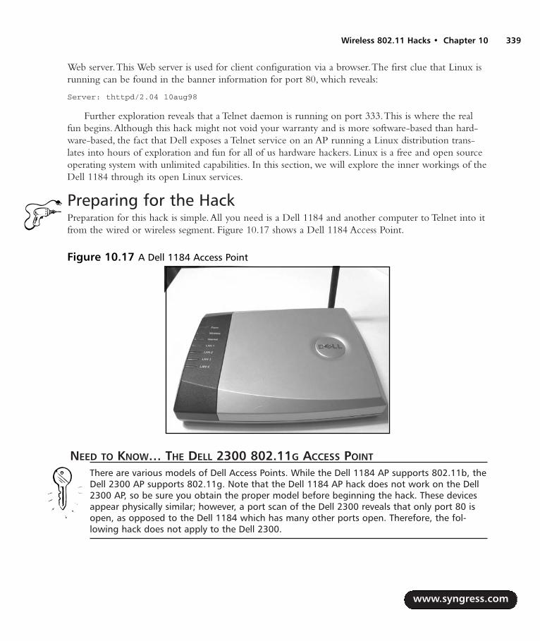
Web server.This Web server is used for client configuration via a browser.The first clue that Linux isrunning can be found in the banner information for port 80, which reveals:
Server: thttpd/2.04 10aug98
Further exploration reveals that a Telnet daemon is running on port 333.This is where the realfun begins.Although this hack might not void your warranty and is more software-based than hard-ware-based, the fact that Dell exposes a Telnet service on an AP running a Linux distribution trans-lates into hours of exploration and fun for all of us hardware hackers. Linux is a free and open sourceoperating system with unlimited capabilities. In this section, we will explore the inner workings of theDell 1184 through its open Linux services.
Preparing for the HackPreparation for this hack is simple.All you need is a Dell 1184 and another computer to Telnet into itfrom the wired or wireless segment. Figure 10.17 shows a Dell 1184 Access Point.
NEED TO KNOW… THE DELL 2300 802.11G ACCESS POINT
There are various models of Dell Access Points. While the Dell 1184 AP supports 802.11b, theDell 2300 AP supports 802.11g. Note that the Dell 1184 AP hack does not work on the Dell2300 AP, so be sure you obtain the proper model before beginning the hack. These devicesappear physically similar; however, a port scan of the Dell 2300 reveals that only port 80 isopen, as opposed to the Dell 1184 which has many other ports open. Therefore, the fol-lowing hack does not apply to the Dell 2300.
www.syngress.com
Wireless 802.11 Hacks • Chapter 10 339
Figure 10.17 A Dell 1184 Access Point
287_HRD_HACK_10.qxd 1/13/04 7:42 PM Page 339

Performing the HackTo begin, fire up your computer and open a DOS prompt or UNIX shell.Telnet to the IP address ofyour 1184 gateway or router on port 333. By default, this address is 192.168.2.1:
C:\>telnet 192.168.2.1 333
By executing this command, you will be presented with a login prompt. For a username, enterroot. For the password, enter the password used by the browser interface (Note that the browser inter-face uses a default username and password of admin). So, if your 1184 is set to the factory default con-figuration, you can log into the Telnet daemon using the username root and the password admin.Asuccessful login will look like this:
login: root
Password: (the password will not be shown as you type it)
#
That’s it! You’re root and you “own the box”, meaning you have complete control of the entiresystem. Want to learn more about your AP? Use the command:
sysconf view
Running this command will give you the following output (note that some parameters may varywith different AP firmware versions):
Sysconf Reading System Parameters from FLASH...DONE!
current parameter size 4204
+==================================================+
| System Configuration Table : valid !!! |
+==================================================+
| System Parameters |
| Host Name : |
| System User ID : root |
| System Password : admin |
+--------------------------------------------------+
| Boot Configuration |
| Boot Method : Auto Boot |
| Vendor Name : Gemtek Taiwan |
| Boot File Name : /home/tftp/vLinux.bin.gz |
| TFTP Server IP Address : 192.168.2.239 |
+--------------------------------------------------+
| LAN (Ethernet) Configuration |
www.syngress.com
340 Chapter 10 • Wireless 802.11 Hacks
287_HRD_HACK_10.qxd 1/13/04 7:42 PM Page 340

| Ethernet H/W Address : 00:90:4b:08:30:75 |
| Ethernet IP Address : 192.168.2.1 |
| Ethernet Default Gateway : 0.0.0.0 |
| Ethernet Subnet Mask : 255.255.255.0 |
+--------------------------------------------------+
+==================================================+
| WAN Setup |
+--------------------------------------------------+
| No Connection Type Selected |
+--------------------------------------------------+
| PPP Configuration |
| PPP User Identifier : |
| PPP User Password : |
| PPP Using PAP Authentification |
| PPP Single Connection |
+--------------------------------------------------+
| IP (Cable Modem) Configuration |
| MAC H/W Address : 00:90:4b:08:30:75 |
| IP Address : 0.0.0.0 |
| Default Gateway : 0.0.0.0 |
| Subnet Mask : 0.0.0.0 |
| Using DHCP for WAN Port |
+--------------------------------------------------+
+==================================================+
| DHCP Server Configuration |
| Invalid DHCP Configuration |
+--------------------------------------------------+
| DNS Server Configuration |
| Domain Name Server : |
| Primary DNS Server IP : 0.0.0.0 |
+--------------------------------------------------+
| NAT Virtual Server Configuration |
| Virtual Server : 0.0.0.0 |
| Virtual Server : 0.0.0.0 |
| Virtual Server : 0.0.0.0 |
www.syngress.com
Wireless 802.11 Hacks • Chapter 10 341
287_HRD_HACK_10.qxd 1/13/04 7:42 PM Page 341

| Virtual Server : 0.0.0.0 |
| Virtual Server : 0.0.0.0 |
| Virtual Server : 0.0.0.0 |
| Virtual Server : 0.0.0.0 |
If you wish, you can change these settings with the command:
sysconf set
Next, let’s take a look at the file system:
# ls -la
drwxr-xr-x 1 root root 32 Jan 01 1970 .
drwxr-xr-x 1 root root 32 Jan 01 1970 ..
drwxr-xr-x 1 root root 32 Jan 01 1970 bin
drwxr-xr-x 1 root root 32 Jan 01 1970 cgi-bin
drwxr-xr-x 1 root root 32 Jan 01 1970 dev
drwxr-xr-x 1 root root 32 Jan 01 1970 etc
drwxr-xr-x 1 root root 32 Jan 01 1970 home
drwxr-xr-x 1 root root 32 Jan 01 1970 images
-rw-r--r-- 1 root root 429 Jan 01 1970 index.html
drwxr-xr-x 1 root root 32 Jan 01 1970 lib
drwxr-xr-x 1 root root 32 Jan 01 1970 mnt
dr-xr-xr-x 25 root root 0 Jan 01 2000 proc
drwxr-xr-x 1 root root 32 Jan 01 1970 tmp
drwxr-xr-x 1 root root 32 Jan 01 1970 usr
drw-rw-rw- 3 root root 1024 Nov 14 23:18 var
Running the command…
cat /etc/hosts
…reveals the following information:
127.0.0.1 vLinux/Vitals_System_Inc.
It appears that this access point is running the vLinux distribution. More information aboutvLinux can also be found at www.onsoftwarei.com/product/prod_vlinux.htm.To continue with ourexperimentation, let’s take a look at the boot-up script by typing the following command:
cat /etc/rc
www.syngress.com
342 Chapter 10 • Wireless 802.11 Hacks
287_HRD_HACK_10.qxd 1/13/04 7:42 PM Page 342

This will result in the following output:
# set default host name
#hostname Wireless_Broadband_Router
# expand /dev/ram0 to ext2 file system
echo "Expand RAM file system image"
/etc/expand /etc/ramfs2048.img /dev/ram0
/etc/expand /etc/ramfs.img /dev/ram1
# mount filesystem and make system directory
echo "Mount filesystem and make system director
mount -n -t proc /proc /proc
mount -n -t ext2 /dev/ram0 /var
mount -n -t ext2 /dev/ram1 /etc/config
chmod 666 /var
chmod 755 /etc
mkdir /var/run
#must be execute before sysconf
checkisp &
reset &
# setup system network
#sysconf config
#sh /etc/bridge
#johnny add
rserver &
reaim &
#server&
#johnny end
#added by tom for start up thttpd
#/bin/thttpd -r -d / &
#/cgi-bin/sysconf.cgi &
Did you notice the #johnny add, #johnny end, and #added by tom for start up thttpd lines? Who areJohnny and Tom? Most likely, they are engineers or developers who helped design the Dell AP or thevLinux distribution. Next, type ps to see the list of running processes, which will show somethinglike:
PID PORT STAT SIZE SHARED %CPU COMMAND
1 S 0K 0K 0.0 init
2 S 0K 0K 0.0 kflushd
www.syngress.com
Wireless 802.11 Hacks • Chapter 10 343
287_HRD_HACK_10.qxd 1/13/04 7:42 PM Page 343

3 S 0K 0K 0.0 kupdate
4 S 0K 0K 0.0 kswapd
16 S 0K 0K 0.0 checkisp
17 S 0K 0K 0.0 reset
18 S 0K 0K 0.0 rserver
19 R 0K 0K 0.2 reaim
21 S0 S 0K 0K 0.0 /bin/login
22 S 0K 0K 0.0 /bin/inetd
23 S 0K 0K 0.0 /bin/thttpd
24 S 0K 0K 0.0 /cgi-bin/sysconf.cgi
61 S 0K 0K 0.0 dproxy
69 S 0K 0K 0.0 dhcpd
79 S 0K 0K 0.0 dhclient
4446 S 0K 0K 0.7 /bin/telnetd
4447 p0 S 0K 0K 0.0 sh
4476 S 0K 0K 0.0 /bin/dporxy
4499 p0 R 0K 0K 0.0 ps
Here, you can see the Web server (/bin/thttpd running as process ID 23) and our Telnet daemon(/bin/telnetd running as process ID 4446).
Want to learn more about the operating system version? Type the following:
cat /proc/version
This will show something similar to:
Linux version 2.2.14-v1.9 ([email protected]) (gcc version 2.9-vLinux-armtool-
0523) #5357 Sat Jan 25 17:39:42 CST 2003
As you can see, the system once again identifies itself as a Linux distribution. What kind of CPU,you wonder? Type this:
cat /proc/cpuinfo
You will see something like the following:
Processor : S3C4510/SEC arm7tdmi rev 0
BogoMips : 44.24
Hardware : <NULL>
Now, would you like to play around with the HTML files that are used in the browser interface?Take a look at the files in /home/httpd. Need to see statistics on frequently used objects in thekernel? Try cat /proc/slabinfo. How about current memory usage details? Try cat /proc/meminfo.You can
www.syngress.com
344 Chapter 10 • Wireless 802.11 Hacks
287_HRD_HACK_10.qxd 1/13/04 7:42 PM Page 344

even play around with IPChains, ping, gzip, ifconfig, reboot, and other utilities. Have fun and explore!The possibilities are endless for experimenting with your Linux-based Dell 1184 Access Point.
Under the Hood: How the Hack WorksSimilar to the USR 2450 Access Point, the Dell 1184 hardware is a single-board computer.The DellAccess Point was designed to run an embedded version of the Linux operating system and all that wasneeded was to Telnet right into its open arms through port 333. It doesn’t require any special tools orreprogramming —it’s ready to go, straight out of the box, giving you an easy path into the excitingworld of hardware hacking!
SummaryIn this chapter, we showed three hardware hacks for wireless networking products. In our first hack,we modified a D-Link DWL-650 wireless NIC to add an external antenna. Most consumer-gradecards do not provide an external antenna connection.Those that do are generally more expensive.However, the D-Link card can be modified to give it support for an external antenna with relativeease. In our hack, we snipped off the end of a Thinnet cable and soldered its BNC connector to theavailable leads on the D-Link card’s PCB. By looking at the PCB, it appears as if the D-Link card hassupport for an external antenna, but it was never implemented.
In our next hack, we explored OpenAP, an open-source Linux distribution from Instant802.TheOpenAP software allows you to reprogram certain brands of off-the-shelf access points with a fullyfunctioning Linux operating system. In our hack, we used a U.S. Robotics USR 2450 AP.The USR2450 has a special jumper on the motherboard that, when shorted, will cause the AP to boot from anSRAM card if one is inserted into the PCMCIA slot. By removing the wireless NIC from thePCMCIA slot and replacing it with a preprogrammed SRAM card containing a OpenAP image file,we can “reflash” the AP’s on-board Flash memory.Then we can remove the SRAM card, replace thewireless NIC, and reboot. Voilá! We now have a Linux machine running on an access point.
In our final hack, we explored the inner workings of the Dell 1184 Access Point.The Dell 1184contains an embedded Linux distribution. No special tools or reprogramming is necessary and we cansimply Telnet to the device on port 333 and gain complete access.
Additional Resources and Other HacksThis section lists a number of interesting Web sites and other wireless-related hardware hacks. If you’reinterested in learning more about the wireless hacking community or just wireless technologies ingeneral, follow these links.
User Groups San Diego Wireless Users Group www.sdwug.org
Bay Area Wireless Users Group www.bawug.org
www.syngress.com
Wireless 802.11 Hacks • Chapter 10 345
287_HRD_HACK_10.qxd 1/13/04 7:42 PM Page 345

Southern California Wireless Users Group www.socalwug.org/
Orange County Wireless Users Group www.occalwug.org/
NYC Wireless www.nycwireless.net
Seattle Wireless www.seattlewireless.net
Personal Telco www.personaltelco.net
Free Networks www.freenetworks.org
Airshare www.airshare.org
Other User Groups www.wirelessanarchy.com/#Community%20Groups
Research and Articles William Arbaugh, Wireless Research Web Page, www.cs.umd.edu/~waa/wireless.html
Tim Newsham, 802.11 Wireless LAN Web Page, www.lava.net/~newsham/wlan
N. Borisov, I. Goldberg, D. Wagner, (In)Security of the WEP Algorithm Web Page,www.isaac.cs.berkeley.edu/isaac/wep-faq.html
P. Shipley,“Open WLANs:The Early Results of War Driving,” 2001,www.dis.org/filez/openlans.pdf
S. Fluhrer, I. Mantin,A. Shamir,“Weaknesses in the Key Scheduling Algorithm of RC4,”Aug 2001, www.wisdom.weizmann.ac.il/~itsik/RC4/Papers/Rc4_ksa.ps
IEEE Standards Wireless Zone Web Page standards.ieee.org/wireless
IEEE 802.11 Working Group Web Page grouper.ieee.org/groups/802/11
WarDriving.com Web Page www.wardriving.com
Products and Tools Airsnort, 64/128-bit WEP key cracker based on flaws in RC4 Key Scheduling Algorithm,
airsnort.sourceforge.net
Network Stumbler www.stumbler.net
MacStumbler (OS X) www.macstumbler.com
bsd-airtools (*BSD) www.dachb0den.com/projects/bsd-airtools.html
NetChaser (Palm OS) www.bitsnbolts.com/netchaser.html
KisMAC (OS X) www.binaervarianz.de/projekte/programmieren/kismac
www.syngress.com
346 Chapter 10 • Wireless 802.11 Hacks
287_HRD_HACK_10.qxd 1/13/04 7:42 PM Page 346

Pocket Warrior (Pocket PC) www.dataworm.net/pocketwarrior/index.html
Nice listing of assorted wireless tools www.networkintrusion.co.uk/wireless.htm
Ethereal Packet capturing tool, www.ethereal.com
prismdump Retrieve raw 802.11 frames with Prism II-based wireless NICs,developer.axis.com/download/tools
WEPCrack 64/128-bit WEP key cracker based on flaws in RC4 Key SchedulingAlgorithm wepcrack.sourceforge.net
www.syngress.com
Wireless 802.11 Hacks • Chapter 10 347
287_HRD_HACK_10.qxd 1/13/04 7:42 PM Page 347

www.syngress.com
348 Chapter 10 • Wireless 802.11 Hacks
287_HRD_HACK_10.qxd 1/13/04 7:42 PM Page 348

Hacking the iPod
Hacks in this Chapter:
Opening Your iPod
Replacing the Battery
Upgrading a 5GB iPod’s Hard Drive
From Mac to Windows and Back Again
iPod Diagnostic Mode
Chapter 11
349
287_HRD_HACK_11.qxd 1/13/04 7:44 PM Page 349

IntroductionAlthough you might not keep tabs on everything Apple does in the computing world, odds are quitegood that you’ve heard of the iPod (see Figure 11.1), announced in October 2001.The iPod has animpressive array of features not previously bundled together in a portable MP3 player. Highlights ofthe initial iPod model included:
Α 5GB internal hard drive
Α FireWire port for transferring files to and from the iPod; this port is also used to chargethe iPod when connected to a Macintosh computer or the separate charger
A compact form factor
An intuitive and easy-to-use interface, which includes a wheel mechanism on the front thatallows you to quickly scroll through menu items and lists of songs
A backlit LCD screen for navigating the user interface
The ability to be used as an external hard drive for storing files and transferring thembetween computers
Apple packaged all these features into a very sleek enclosure with a white face and reflective, stain-less steel back.At the time the iPod was introduced, Flash ROM-based MP3 players were the norm, andhard drive-based devices were not very common. Because of the large capacity of hard drives comparedto solid-state memory, the initial 5GB version of the iPod allowed the user to carry around an impres-sive amount of music relative to other players.The FireWire interface also addressed the growingproblem of the USB interface employed by most MP3 players, since that version of USB (not the newerUSB 2) is notoriously slow at copying large amounts of data. With all these features so well integrated
www.syngress.com
350 Chapter 11 • Hacking the iPod
Figure 11.1 The 5GB First-Generation iPod (Left) and the 20GB Third-Generation iPod (Right)
287_HRD_HACK_11.qxd 1/13/04 7:44 PM Page 350
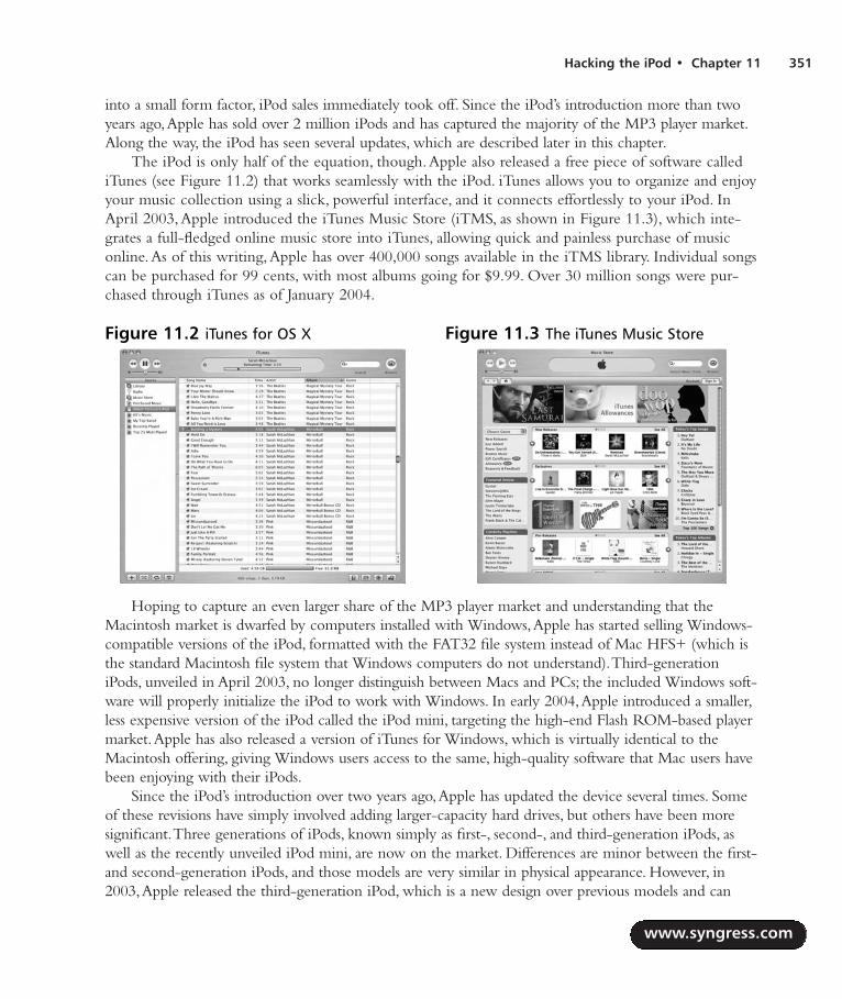
Hacking the iPod • Chapter 11 351
into a small form factor, iPod sales immediately took off. Since the iPod’s introduction more than twoyears ago,Apple has sold over 2 million iPods and has captured the majority of the MP3 player market.Along the way, the iPod has seen several updates, which are described later in this chapter.
The iPod is only half of the equation, though.Apple also released a free piece of software callediTunes (see Figure 11.2) that works seamlessly with the iPod. iTunes allows you to organize and enjoyyour music collection using a slick, powerful interface, and it connects effortlessly to your iPod. InApril 2003,Apple introduced the iTunes Music Store (iTMS, as shown in Figure 11.3), which inte-grates a full-fledged online music store into iTunes, allowing quick and painless purchase of musiconline.As of this writing,Apple has over 400,000 songs available in the iTMS library. Individual songscan be purchased for 99 cents, with most albums going for $9.99. Over 30 million songs were pur-chased through iTunes as of January 2004.
Hoping to capture an even larger share of the MP3 player market and understanding that theMacintosh market is dwarfed by computers installed with Windows,Apple has started selling Windows-compatible versions of the iPod, formatted with the FAT32 file system instead of Mac HFS+ (which isthe standard Macintosh file system that Windows computers do not understand).Third-generationiPods, unveiled in April 2003, no longer distinguish between Macs and PCs; the included Windows soft-ware will properly initialize the iPod to work with Windows. In early 2004,Apple introduced a smaller,less expensive version of the iPod called the iPod mini, targeting the high-end Flash ROM-based playermarket.Apple has also released a version of iTunes for Windows, which is virtually identical to theMacintosh offering, giving Windows users access to the same, high-quality software that Mac users havebeen enjoying with their iPods.
Since the iPod’s introduction over two years ago,Apple has updated the device several times. Someof these revisions have simply involved adding larger-capacity hard drives, but others have been moresignificant.Three generations of iPods, known simply as first-, second-, and third-generation iPods, aswell as the recently unveiled iPod mini, are now on the market. Differences are minor between the first-and second-generation iPods, and those models are very similar in physical appearance. However, in2003,Apple released the third-generation iPod, which is a new design over previous models and can
www.syngress.com
Figure 11.2 iTunes for OS X Figure 11.3 The iTunes Music Store
287_HRD_HACK_11.qxd 1/13/04 7:44 PM Page 351

quickly be distinguished from those earlier models. Figure 11.1 shows a pair of iPods side by side—afirst-generation iPod on the left and a third-generation on the right.The differences between the variousiPod iterations are detailed here:
First generation Introduced in October 2001 and available initially with a 5GB drive.A10GB model was added later.These first-generation iPods feature a mechanical scroll wheelthat physically rotates about a center Action button.All the buttons on the front face aremechanical.The top of the iPod features a white, plastic plate around the FireWire port,headphone jack, and Hold switch.
Second generation Available in 10GB and 20GB versions, the second-generation iPodsreplaced the moving scroll wheel with a touch-sensitive, solid-state touch wheel.The but-tons on the front face remain the same, but the top plate is stainless steel as opposed to thewhite plastic of the first generation, and the FireWire port includes a built-in cover. Second-generation iPods are available in Macintosh and Windows-specific versions, although theycan easily be reformatted to work with either operating system.A remote control and aniPod case came standard with the unit.
Third generation Third-generation iPods were introduced with a completely new formfactor, although one that is still immediately recognizable as an iPod. Gone are the buttonsaround the touch wheel, replaced by a row of four touch-sensitive, backlit buttons immedi-ately above the wheel.Third-generation iPods are noticeably thinner than previous iPods,thanks to a much smaller and lower-capacity internal battery.A new docking port is locatedat the bottom of the unit, and the wired remote and headphone plugs have been separatedinto two distinct jacks at the top. Higher-capacity models come standard with a dock, awired remote, and a case.These accessories can also be purchased separately.Third-genera-tion iPods work with both Macintosh and Windows computers—the included Windowsinstallation software reformats the hard drive appropriately.As of this writing,Apple isoffering third-generation iPods in 15GB, 20GB, and 40GB configurations.
iPod mini In January 2004,Apple introduced a new line of iPods dubbed the iPod mini.Designed to compete with the high-end Flash ROM-based (solid-state memory) playermarket, the iPod mini features a 4GB hard drive in a form factor the width and height of abusiness card and only 1/2” thick. Encased in anodized aluminum and available in fivecolors, the iPod mini features the same user interface as its full-sized siblings and supportsFireWire and USB 2. In order to save space on the front face,Apple made the four buttonsfound on the third-generation iPod part of the touch wheel, which now doubles as a four-function button (each compass direction on the wheel can be pressed to activate thebutton). Because the iPod mini was introduced as this book was being completed, we discussonly the full-size iPods in this chapter.
www.syngress.com
352 Chapter 11 • Hacking the iPod
287_HRD_HACK_11.qxd 1/13/04 7:44 PM Page 352
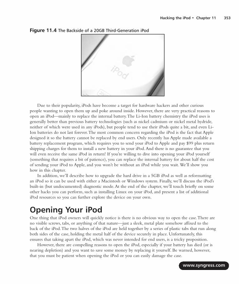
Hacking the iPod • Chapter 11 353
Due to their popularity, iPods have become a target for hardware hackers and other curiouspeople wanting to open them up and poke around inside. However, there are very practical reasons toopen an iPod—mainly to replace the internal battery.The Li-Ion battery chemistry the iPod uses isgenerally better than previous battery technologies (such as nickel cadmium or nickel metal hydride,neither of which were used in any iPods), but people tend to use their iPods quite a bit, and even Li-Ion batteries do not last forever.The most common concern regarding the iPod is the fact that Appledesigned it so the battery cannot be replaced by end users. Only recently has Apple made available abattery replacement program, which requires you to send your iPod to Apple and pay $99 plus returnshipping charges for them to install a new battery in your iPod.And there is no guarantee that youwill even receive the same iPod in return! If you’re willing to dive into opening your iPod yourself(something that requires a bit of patience), you can replace the internal battery for about half the costof sending your iPod to Apple, and you won’t be without an iPod while you wait. We’ll show youhow in this chapter.
In addition, we’ll describe how to upgrade the hard drive in a 5GB iPod as well as reformattingan iPod so it can be used with either a Macintosh or Windows system. Finally, we’ll discuss the iPod’sbuilt-in (but undocumented) diagnostic mode.At the end of the chapter, we’ll touch briefly on someother hacks you can perform, such as installing Linux on your iPod, and present a list of additionaliPod resources so you can further explore the device on your own.
Opening Your iPodOne thing that iPod owners will quickly notice is there is no obvious way to open the case.There areno visible screws, tabs, or anything of that nature—just a sleek, metal plate somehow affixed to theback of the iPod.The two halves of the iPod are held together by a series of plastic tabs that run alongboth sides of the case, holding the metal half of the device securely in place. Unfortunately, thisensures that taking apart the iPod, which was never intended for end users, is a tricky proposition.
However, there are compelling reasons to open the iPod, especially if your battery has died (or isnearing depletion) and you want to save some money by replacing it yourself. Be warned, however,that you must be patient when opening the iPod or you can easily damage the case.
www.syngress.com
Figure 11.4 The Backside of a 20GB Third-Generation iPod
287_HRD_HACK_11.qxd 1/13/04 7:44 PM Page 353

Preparing for the HackWe will separately describe how to open a first-generation iPod and a second- or third-generationiPod.The best tool to open your iPod with is some type of stiff plastic, such as the wedges we’ll usebelow. If you can avoid it, do not use a metal screwdriver to pry your iPod open, as the risk of dam-aging the case is much greater.The metal case can be permanently bent and the plastic of the casewill scratch easily, so care and patience must be applied when opening the iPod. One of the batterykits we purchased came from PDASmart (www.pdasmart.com) and include two plastic sticks withtapered, wedge ends (not unlike a flathead screwdriver) which are ideal for opening iPods (see Figure11.5). We also purchased batteries from Laptops For Less (www.laptopsforless.com), and they include asingle jeweler’s screwdriver for opening the iPod.
WARNING: HARDWARE HARM
Apple never intended end users to open the iPod and thus made it rather difficult to do so.The iPod is held together by a series of plastic tabs that clip onto the metal part of the case.To open the case, you must exert force between the plastic half of the case and the metalhalf to flex the case enough so the tabs become detached from the metal. In doing this, youcan permanently bend the metal half of the case, as well as cause cosmetic damage to theplastic half along the seam where the two halves come together.
Therefore, extreme patience and care are required when you’re attempting to open aniPod. Using a tool to pry into the case can very easily bend the metal, so you must be diligentand work slowly. If you use a small screwdriver you’ll want to be especially careful not to slipwhen exerting force while prying, as you can easily put a nice gouge in the case exterior.
First-generation iPods are easier to open as you can begin prying at the top of the case near theFireWire port. Second and third-generation iPods do not have this advantage, so you must start alongone of the sides.
www.syngress.com
354 Chapter 11 • Hacking the iPod
Figure 11.5 Plastic Wedges for Opening an iPod
287_HRD_HACK_11.qxd 1/13/04 7:44 PM Page 354

First Generation iPodsLet’s begin:
1. Using one of the wedges, start by prying between the stainless steel cover and the plastic ofthe case at the top of the iPod (see Figure 11.6). Prying at the top will allow you to open asmall gap on the side of the case where you can then use one of the other wedges to startundoing the plastic tabs.To see what you’re aiming for, look ahead to Figure 11.9, whichshows what the tabs look like when the case is open.
2. With one wedge firmly in place at the top of the iPod, use a second wedge to start workingalong the side, as shown in Figure 11.7.
www.syngress.com
Hacking the iPod • Chapter 11 355
Figure 11.6 Start Prying at the Top of the Case
Figure 11.7 Working Along the Edge
287_HRD_HACK_11.qxd 1/13/04 7:44 PM Page 355

3. Continue working your way along the edge of the iPod until you have all the clips on oneside undone (see Figure 11.8).
4. Once you reach the corner opposite from where you started and have all the clips undoneon one side of the iPod, you are past the most difficult stage and can separate the two halves(see Figure 11.9).You may now proceed with other hacks, such as replacing the iPod batteryor swapping out the hard drive, which are described later in this chapter.
Second and Third-Generation iPodsApple changed the design of the second-generation iPods so you can’t start prying at the top of theunit near the FireWire port.Third-generation iPods constitute a completely new design over the firsttwo iPod generations and suffer a similar problem. Unfortunately, this makes them a bit trickier toopen. While we depict a third-generation iPod in the pictures, the procedure is similar for second-generation iPods.
www.syngress.com
356 Chapter 11 • Hacking the iPod
Figure 11.8 Continue Working Down the Edge
Figure 11.9 Lifting Apart the Two Halves of the iPod
287_HRD_HACK_11.qxd 1/13/04 7:44 PM Page 356

1. Work one of the plastic wedges along the seam on the side of the iPod until you are able toinsert it between the metal back and the case (see Figure 11.10).
2. With one of the wedges inserted in the case, insert a second wedge into the gap you’ve cre-ated and work it along the edge to pop out the tabs holding the case together.Your goal isto push each of the tabs inward until they release from the metal half of the case.
3. Continue working along the one side until you have all the tabs unclipped (see Figure 11.12).
www.syngress.com
Hacking the iPod • Chapter 11 357
Figure 11.10 Prying into the Case
Figure 11.11 Continue Prying Along One Side
287_HRD_HACK_11.qxd 1/13/04 7:44 PM Page 357

4. With one side unclipped, you should be able to separate the back of the iPod from the fronthalf (see Figure 11.13).
If you’re opening a third-generation iPod, the metal half of the case is connected to the bottomhalf by a thin ribbon cable. Do not try separating the two halves completely without first discon-necting the cable or you may do permanent harm to your iPod. Figure 11.14 shows where the cableis connected to the top half of the case.You can choose to either disconnect the cable or leave it con-nected and flip the metal half of the case over so it is resting next to the top half of the case.
www.syngress.com
358 Chapter 11 • Hacking the iPod
Figure 11.12 Unclip all the Tabs
Figure 11.13 Opening the Case
287_HRD_HACK_11.qxd 1/13/04 7:44 PM Page 358

WARNING: HARDWARE HARM
Unlike first- and second-generation iPods, the third-generation iPods’ metal cover is con-nected to the top half of the unit with a thin ribbon cable. Do not be hasty in separating thetwo halves, because you can easily damage this cable. You can choose to disconnect thecable (the connector is shown in Figure 11.14) or carefully place the two halves of the caseclose to each other on a flat surface while working on the iPod internals.
With your iPod open, you may now proceed with the hack of your choice, including replacingthe iPod battery or swapping out the hard drive, both of which are described in this chapter.
Replacing the iPod BatterySooner or later, it will come time to replace your iPod’s battery. Li-Ion power cells are a big improve-ment over older battery chemistries, but they are not infallible. Eventually your iPod’s battery will nolonger hold a charge or it will be sufficiently weak where you’re not getting nearly as much time outof your iPod as you did when it was new. When that time comes, you have three choices:
1. Throw out your iPod and buy a new one Apple would love you to choose thisoption, but most people do not consider the iPod a “disposable” item, given its high pricetag.Thus, this is not an option for the majority of people.
2. Send your iPod to Apple and pay them to replace the battery Apple recently begana program whereby you can send them your iPod and, for $99 (plus shipping and sales tax ifapplicable), they will replace its battery. Besides being relatively expensive, this choicedeprives you of your iPod while you’re waiting for Apple to return it.Also,Apple makes noguarantee that you’ll receive your original iPod back.
3. Open your iPod and replace the battery yourself Several companies sell iPod bat-teries for around $50 and often include a tool (a screwdriver or plastic implement) that you
www.syngress.com
Hacking the iPod • Chapter 11 359
Figure 11.14 Connector Holding Two Halves Together
287_HRD_HACK_11.qxd 1/13/04 7:44 PM Page 359

can use to open your iPod. Once you have the device open, swapping the old battery for anew one is relatively trivial. Opening the iPod is the hardest part.
Since you’re reading a book on hardware hacking, we’ll assume that you’re opting to replace thebattery yourself.
NEED TO KNOW… IPOD BATTERY LAWSUIT?Just before this book went to press, the law firm of Girard Gibbs & De Bartolomeo LLPposted a page on its Web site called “Investigation of Apple’s iPod.” The firm indicated thatit is “investigating a potential class action against Apple Computer, Inc., on behalf of iPodowners whose batteries have died or lost their ability to hold their charge.” The Web pagehas since been taken down, but while it was up the firm was asking iPod users who experi-enced problems with their battery to submit information via a form on the page.
After the page was posted, Apple began offering a battery replacement program, but it’sunclear if this potential litigation had any influence on Apple’s decision to set up the program.
Preparing for the HackFor this hack, all you need is a tool to open the iPod (a plastic wedge or two, a firm piece of thinplastic, a small screwdriver, or something similar) and a replacement battery.
To demonstrate this hack, we ordered new batteries from Laptops for Less(www.laptopsforless.com) and PDASmart (www.pdasmart.com).At the time of this writing, the bat-teries cost $50 to $60 each, plus shipping. PDASmart also offers a mail-in service that is less expensivethan Apple’s battery replacement program.You can also find iPod batteries for sale on eBay, but if yougo this route you need to be careful not to end up purchasing a used battery that might be in worsecondition than the battery you intend to replace.
NEED TO KNOW…Apple made many changes to the iPod when it designed the third-generation models, thebattery being one of them. Third-generation iPods have a much smaller battery than earliermodels, presumably to reduce the thickness of the iPod. Although Apple certainly succeededin making the newer iPods thinner, the third-generation iPods have a noticeably shorter bat-tery life as a result. Figure 11.15 shows the difference in size between the two batteries.
When ordering a new battery for your iPod, you want to make sure you specify the cor-rect battery type. You’ll be pretty disappointed if you open your iPod up only to discover thatyou ordered the wrong battery.
www.syngress.com
360 Chapter 11 • Hacking the iPod
287_HRD_HACK_11.qxd 1/13/04 7:44 PM Page 360

Since the battery and internals are unique between the first- and second-generation iPods and thethird-generation iPods, we will describe battery replacement separately.
Battery Replacement: First- and Second-Generation iPodsFollow these steps:
1. The first thing you’ll want to do is open your iPod, as described in the first section of thischapter. Once you have the iPod open, put aside the metal half of the case and place youriPod face down on a flat surface, as shown in Figure 11.16.The battery is sitting on top.
2. The battery is connected to the iPod motherboard by a power connector visible at the lower-left corner of Figure 11.16. Holding the battery in place are two thin rubber strips at bothends of the iPod, sandwiched between the battery and the hard drive (which is directly under-
www.syngress.com
Hacking the iPod • Chapter 11 361
Figure 11.15 iPod Batteries: First- and Second-Generation (Top) and Third-Generation(Bottom)
Figure 11.16 The First-Generation iPod Opened and Ready for the Hack
287_HRD_HACK_11.qxd 1/13/04 7:44 PM Page 361

neath the battery). Figure 11.17 shows one of these strips at the top of the iPod. In this pic-ture, you can also more clearly see the battery power cable plugged into the motherboard.
3. Using a screwdriver, carefully pry between the hard drive and the battery, undoing the glueon the rubber pieces, as shown in Figure 11.18.
4. Once you have separated the battery from the rubber strips, you can unplug it from theiPod motherboard and properly dispose of it (see Figure 11.19).
www.syngress.com
362 Chapter 11 • Hacking the iPod
Figure 11.17 Rubber Strips
Figure 11.18 Prying the Battery from the Rubber Strips
287_HRD_HACK_11.qxd 1/13/04 7:44 PM Page 362

5. With the old battery removed, you can now swap in the new battery that you purchased(see Figure 11.20). Orient the new battery in the same direction as the old battery. Plug thepower connector into the iPod motherboard, taking care as you insert the connector.Theconnector will fit in only one orientation; so do not force it into place. For easier access tothe connector on the motherboard, you can temporarily move aside the rubber strip thatpartially covers it.
6. With the new battery connected, move the rubber strip back into place (if you moved itout of the way) and firmly attach the battery atop the hard drive, as shown in Figure 11.21.
www.syngress.com
Hacking the iPod • Chapter 11 363
Figure 11.19 Removing the Old Battery
Figure 11.20 Connecting the New Battery
287_HRD_HACK_11.qxd 1/13/04 7:44 PM Page 363

7. Take care that the power cable is tucked away at the top of the iPod (see Figure 11.22).
8. Once you have the battery securely attached into place, you can reattach the cover (seeFigure 11.23).The metal cover should snap easily into place. If it does not, make sure thereare no obstructions before you attempt to close the cover.
www.syngress.com
364 Chapter 11 • Hacking the iPod
Figure 11.21 Affixing the Battery to the Hard Drive
Figure 11.22 Power Cable Safely Tucked Away
287_HRD_HACK_11.qxd 1/13/04 7:44 PM Page 364

9. Once you have your iPod back together, you’ll want to charge the battery for a minimumof three hours before using the device (see Figure 11.24).
Battery Replacement: Third-Generation iPodsFollow these steps:
1. Carefully open your third-generation iPod as described in the first section of this chapter.Once you have your iPod opened, it should resemble the image in Figure 11.25.
www.syngress.com
Hacking the iPod • Chapter 11 365
Figure 11.23 Reattaching the Metal Half of the Case
Figure 11.24 Charging the New Battery
287_HRD_HACK_11.qxd 1/13/04 7:45 PM Page 365

2. First, you’ll need to remove the hard drive (see Figure 11.26).The hard drive is sitting ontop of the other iPod circuitry, buffered by a piece of blue rubber.The hard drive is con-nected to the iPod via a small ribbon cable that connects directly to the motherboard.Slowly lift up the hard drive to disconnect this cable, and set the hard drive aside.
3. Now that the hard drive has been removed, we have easy access to the battery.The battery isthe large black component highlighted in Figure 11.27.The battery connector is immedi-ately to the left of the battery (see Figure 11.28).
www.syngress.com
366 Chapter 11 • Hacking the iPod
Figure 11.25 The Third-Generation iPod Opened and Ready for the Hack
Figure 11.26 Removing the Hard Drive
287_HRD_HACK_11.qxd 1/13/04 7:45 PM Page 366

4. Carefully use a small screwdriver to pry the battery from its compartment. Be careful not tomake contact with the circuit board below the battery, because you could damage it. Beforethe battery can be completely removed, you will need to disconnect the power cord.However, the cord is wrapped around a part of the circuit board, as shown in Figure 11.28.You can use a screwdriver to help remove the wires from underneath the board.
5. With the wires out of the way, you can remove the battery from its compartment in theiPod, as shown in Figure 11.29.
www.syngress.com
Hacking the iPod • Chapter 11 367
Figure 11.27 The iPod Battery
Figure 11.28 The iPod Battery Connector
287_HRD_HACK_11.qxd 1/13/04 7:45 PM Page 367

6. Disconnect the battery from the motherboard by gently pulling the power connectorstraight up. With the old battery removed, you can now plug the new battery in, taking careas you insert the connector (see Figure 11.30).The connector will only fit in one orienta-tion, so do not force it into place.
7. Before you can place the battery back into its compartment, you must first wrap the batterypower cord around the tip of the circuit board.You can use a small screwdriver to assist you,as shown in Figure 11.31.
www.syngress.com
368 Chapter 11 • Hacking the iPod
Figure 11.29 The iPod Battery Removed
Figure 11.30 Inserting the New iPod Battery
287_HRD_HACK_11.qxd 1/13/04 7:45 PM Page 368

8. Once you have reattached and properly routed the power cable, you can place the new bat-tery inside the case.Your iPod should now resemble the image in Figure 11.32.
9. Now you can reassemble your iPod. Reattach the connector on the hard drive to the con-nector on the motherboard.The connectors are highlighted in Figure 11.33.
www.syngress.com
Hacking the iPod • Chapter 11 369
Figure 11.31 Tucking In the Power Cable
Figure 11.32 New Battery Installed in Place
287_HRD_HACK_11.qxd 1/13/04 7:45 PM Page 369
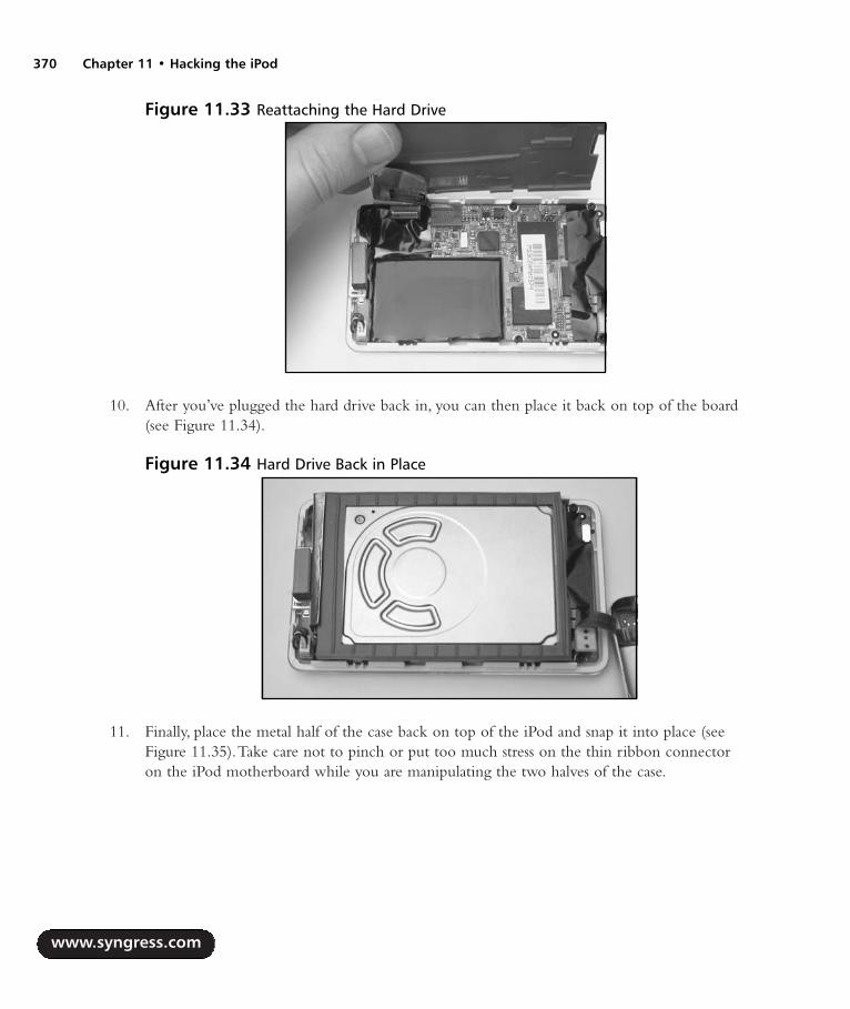
10. After you’ve plugged the hard drive back in, you can then place it back on top of the board(see Figure 11.34).
11. Finally, place the metal half of the case back on top of the iPod and snap it into place (seeFigure 11.35).Take care not to pinch or put too much stress on the thin ribbon connectoron the iPod motherboard while you are manipulating the two halves of the case.
www.syngress.com
370 Chapter 11 • Hacking the iPod
Figure 11.33 Reattaching the Hard Drive
Figure 11.34 Hard Drive Back in Place
287_HRD_HACK_11.qxd 1/13/04 7:45 PM Page 370

12. Once you have your iPod back together, you’ll want to charge the battery for a minimumof three hours before using the device (see Figure 11.36).
Upgrading a 5GB iPod’s Hard DriveThe first iPod Apple released contained a 5GB hard drive, which was an impressive amount of storageat the time. However, it has since been eclipsed by iPods with much larger disk space.The largest iPodavailable as this book goes to press is a 40GB version, allowing for up to eight times the storage of theearly 5GB iPods. Unfortunately, the iPod uses a PCMCIA form-factor 1.8-inch hard drive made byToshiba, and replacement drives are not easy to obtain. However, used iPod drives come up frequentlyfor auction on eBay, giving you an opportunity to either upgrade your 5GB iPod to a higher capacityor replace a nonworking drive with a good one to get your iPod back in working order.
www.syngress.com
Hacking the iPod • Chapter 11 371
Figure 11.35 Snapping the Case Back Together
Figure 11.36 Charging the new Battery
287_HRD_HACK_11.qxd 1/13/04 7:45 PM Page 371

Keep in mind that there is a fairly limited upgrade path for the 5GB iPod. Drives from third-gen-eration iPods will not work in the first-generation iPod, and drives larger in capacity than 10GB (suchas the 20GB drive used in the second-generation iPod) will not fit in the first-generation case due tothe increase in thickness.
Preparing for the HackFor this hack you’ll need the following:
A 5GB iPod that you want to upgrade
A replacement hard drive (an example is shown in Figure 11.37)
A tool for opening the iPod (such as one or two plastic wedges, a thin, firm piece of plastic,or a flat-head screwdriver)
eBay is a good source for used iPod drives, and they can often be found for much less than you’dpay to buy a new (or used) iPod. If you’re unsure of the drive’s capacity, you can find it printed in thelower-left corner of the sticker on the top of the drive (highlighted in Figure 11.38).
Performing the HackThe first thing you’ll want to do is open your iPod as described in the first section in this chapter.When you have the case off, your iPod should resemble the image in Figure 11.39.
www.syngress.com
372 Chapter 11 • Hacking the iPod
Figure 11.37 A 10GB iPod Hard DriveFigure 11.38 Drive Capacity Printed onthe Hard Drive Sticker
287_HRD_HACK_11.qxd 1/13/04 7:45 PM Page 372

1. To get to the hard drive, we first have to remove the battery that sits on top of it.The bat-tery is held into place by sticky rubber pads sandwiched between the battery and the harddrive.The battery is also connected to the motherboard with a power cable.The easiest wayto remove the battery is to use a small screwdriver as a lever (see Figure 11.40).Take carenot to exert force with the tip of the screwdriver on either the battery or the hard drive,because you may puncture them; instead, use the shaft of the screwdriver to pry between thebattery and the hard drive.
2. Once you have peeled the battery off the top of the hard drive, it will still be connected to themotherboard. Before disconnecting the battery, let’s first remove the rubber pads from the topof the hard drive (see Figure 11.41), because one of them may be obscuring access to the bat-tery connector and we need to remove the pads anyway to apply them to the new drive. Notethat the rubber pads in your iPod may not look exactly the same as those pictured.
www.syngress.com
Hacking the iPod • Chapter 11 373
Figure 11.39 iPod Opened and Ready for the Hack
Figure 11.40 Pulling the Battery and Hard Drive Apart
287_HRD_HACK_11.qxd 1/13/04 7:45 PM Page 373
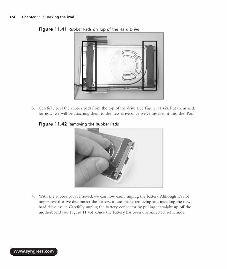
3. Carefully peel the rubber pads from the top of the drive (see Figure 11.42). Put them asidefor now; we will be attaching them to the new drive once we’ve installed it into the iPod.
4. With the rubber pads removed, we can now easily unplug the battery.Although it’s notimperative that we disconnect the battery, it does make removing and installing the newhard drive easier. Carefully unplug the battery connector by pulling it straight up off themotherboard (see Figure 11.43). Once the battery has been disconnected, set it aside.
www.syngress.com
374 Chapter 11 • Hacking the iPod
Figure 11.41 Rubber Pads on Top of the Hard Drive
Figure 11.42 Removing the Rubber Pads
287_HRD_HACK_11.qxd 1/13/04 7:45 PM Page 374

5. With the battery out of the way, we can now remove the hard drive.The hard drive isresting on four small rubber pads and is plugged into the motherboard with a connector onone edge of the hard drive. Carefully pry the bottom of the hard drive from each rubberpad (see Figure 11.44).
WARNING: HARDWARE HARM
Be extremely careful in performing this procedure. Do not use the motherboard as directleverage for prying up the hard drive, because you can easily damage the motherboard andrender your iPod inoperable. Instead, wedge the screwdriver between the rubber pads andthe hard drive, as shown in Figure 11.44.
www.syngress.com
Hacking the iPod • Chapter 11 375
Figure 11.43 Disconnecting the Battery
Figure 11.44 Prying the Hard Drive from the Rubber Pads
287_HRD_HACK_11.qxd 1/13/04 7:45 PM Page 375

6. Once you have separated the drive from the rubber pads, you can disconnect the drive fromthe connector on the motherboard.This connector is very fragile, so take care whenunplugging it from the drive.The easiest way to do so is to wedge a flat-head jeweler’sscrewdriver between the drive and connector to work it loose (see Figure 11.45).After youdisconnect the drive, you can set it aside.
7. If any of the rubber pads are still attached to the hard drive, remove them and place them inthe appropriate corner of the motherboard, where they were originally resting.Your iPodshould now resemble the image in Figure 11.46.
8. Now it’s time to attach the new drive. Before you plug the drive in, make sure it is orientedthe same way as the old drive.The drive connector is keyed and can be plugged into themotherboard only one way (see Figure 11.47).
www.syngress.com
376 Chapter 11 • Hacking the iPod
Figure 11.45 Disconnecting the Hard Drive
Figure 11.46 Exposed iPod Motherboard
287_HRD_HACK_11.qxd 1/13/04 7:45 PM Page 376

Taking care that the drive is oriented properly (the label side of the drive should befacing the iPod motherboard), plug the hard drive in as shown in Figure 11.48. Do notexert too much force when plugging in the drive—if it doesn’t slide in easily, make sure thedrive is not upside down.
9. After plugging the drive into the connector, place it back on the motherboard’s rubber pads,taking care that the drive is properly centered in the case. With the drive placed in the case,it should resemble Figure 11.49.
www.syngress.com
Hacking the iPod • Chapter 11 377
Figure 11.47 The Hard Drive Connector
Figure 11.48 Plugging In the New Hard Drive
287_HRD_HACK_11.qxd 1/13/04 7:45 PM Page 377

10. Now it’s time to plug the battery back into the motherboard. Carefully plug the connectorinto the board, taking care that the plug is oriented in the right direction.The plug is keyedand will fit into the connector only one way, so do not try to force it (see Figure 11.50).
11. Now replace the long rubber pads that you removed earlier by attaching them to thereplacement drive in the same locations as they were on the old drive (see Figure 11.51).Note that the rubber pads in your iPod might not exactly resemble those in the picture.
www.syngress.com
378 Chapter 11 • Hacking the iPod
Figure 11.49 The New Hard Drive Resting in the Case
Figure 11.50 Reattaching the Battery
287_HRD_HACK_11.qxd 1/13/04 7:45 PM Page 378

12. After replacing the rubber pads, place the battery on top of the hard drive.Take care toproperly align the battery on top of the hard drive, or you may have problems getting thecase back together.Also, tuck the battery power cable underneath the metal housing at thetop of the iPod to move it out of the way (see Figure 11.52).Apply enough pressure to thebattery to ensure that it is firmly attached to the rubber pads.
13. Fold the two pieces of metal foil back over the battery. Finally, snap the stainless steel coverback over the case (see Figure 11.53). If the cover does not slide easily over the case, makesure there are no obstructions before continuing.The cover should snap into place easily.
www.syngress.com
Hacking the iPod • Chapter 11 379
Figure 11.51 Replacing the Rubber Pads
Figure 11.52 Battery Back in Place
287_HRD_HACK_11.qxd 1/13/04 7:45 PM Page 379

14. After you’ve got the iPod back together, turn it on. If the upgrade was successful, youshould be able to use your new iPod immediately (see Figure 11.54).
Of course, you’ll probably want to plug your iPod into your computer and copy your music ontoit. If you upgraded your iPod with a larger hard drive (going from 5GB to 10GB, as we did in thischapter), you now have twice as much storage space. If the drive was formatted for use with aMacintosh and you need to use your iPod with a Windows machine, or vice versa, read the next sec-tion, which explains how you can perform this magic.
www.syngress.com
380 Chapter 11 • Hacking the iPod
Figure 11.53 Replace the Cover
Figure 11.54 Ahhh, Music!
287_HRD_HACK_11.qxd 1/13/04 7:45 PM Page 380

From Mac to Windows and Back AgainFirst-generation iPods were intended for use solely with Macintosh computers.As demand for theiPod grew,Apple released the second-generation iPods, which included support for Windows com-puters.To this end,Apple sold two different versions of the second-generation iPod—models forWindows computers and models for Macs.Third-generation iPods do away with this duplicity inpackaging and simply come with an install disk that will properly format the iPod’s hard drive forWindows (new iPods come pre-formatted with the Macintosh HFS+ file system). Fortunately, alliPods can be formatted to work with Windows or the Macintosh using software available from Apple.
Preparing for the HackAll you need for this hack are the following:
An iPod you’d like to “switch”
A Windows or Macintosh computer with a FireWire port (or a USB port if you have athird-generation iPod)
An Internet connection so you can download the appropriate software from Apple’s Web site
WARNING
Performing this procedure will cause the iPod Updater software to reformat your iPod’s harddrive with a new file system, thus deleting anything stored on the drive. If you have music orother files stored on your iPod and you don’t want to lose them, make sure you first back upthe files onto your computer!
Going from Windows to MacintoshIf you’re using a first- or second-generation iPod, you will need to download the iPod SoftwareUpdater 1.3.1. If you’re using a third-generation iPod, you will need to download the iPod SoftwareUpdater 2.0.1 (or later) instead.The updaters can be found at www.info.apple.com/usen/ipod.
1. After downloading the correct version of the software for your iPod, run the updater, asshown in Figure 11.55.This example demonstrates using the iPod Software Updater 1.3.1,but the procedure is similar for later Updater versions.
www.syngress.com
Hacking the iPod • Chapter 11 381
287_HRD_HACK_11.qxd 1/13/04 7:45 PM Page 381

2. Go through the install process, which will install the updater on your computer. Wheninstallation is complete, plug your iPod into your Macintosh. Locate the iPod SoftwareUpdater on your computer, which should be located in your Applications | Utilitiesfolder.
3. With your iPod plugged into your Macintosh, start the iPod Software Updater by double-clicking the iPod Software Updater icon (see Figure 11.56). Click the lock icon in thelower-left corner of the dialog box, type in your password, and click the Restore button(see Figure 11.57).
4. After you click Restore, you will be prompted with a confirmation dialog box. Confirmthat you want to restore your iPod to its factory settings.After the updater has completed,unplug the iPod and then plug it back into your computer.That’s it! Now you can copymusic and other files onto your iPod.
www.syngress.com
382 Chapter 11 • Hacking the iPod
Figure 11.55 The Macintosh iPod Software Updater Installer
Figure 11.56 The iPod Software UpdaterIcon Figure 11.57 The iPod Software Updater
287_HRD_HACK_11.qxd 1/13/04 7:45 PM Page 382

Going from Macintosh to WindowsIf you’re using a first- or second-generation iPod, you will need to download the Windows 1.3 iPodUpdater. If you’re using a third-generation iPod, you will need to download the Windows 2.1 (orlater) iPod Updater instead.The updaters can be found at www.info.apple.com/usen/ipodwin.
1. After downloading the appropriate software, locate and run the installer, as shown in Figure11.58. Go through the install process, which will install the updater on your computer.Thisexample demonstrates restoring an iPod using the iPod Software Updater 1.3, but the pro-cedure is similar for later Updater versions.
2. If your iPod is connected to your Windows computer, eject it and unplug it from the com-puter. Locate the iPod Updater that you just installed (see Figure 11.59). It should belocated under Start | Programs | iPod | System Software 1.3 (or 2.1 if you’reinstalling that version instead).
www.syngress.com
Hacking the iPod • Chapter 11 383
Figure 11.58 The Windows iPod Software Updater Installer
Figure 11.59 Locate and Run the iPod Updater
287_HRD_HACK_11.qxd 1/13/04 7:45 PM Page 383

3. After you start the Updater, plug your iPod into the computer.The iPod installer screenshould acknowledge that the iPod has been plugged in and resemble the image shown inFigure 11.60.
4. Now click the Restore button.After the updater has completed, unplug the iPod and thenplug it back into your computer.That’s it! Now you can copy music and other files ontoyour iPod.
iPod Diagnostic ModeThe iPod has several built-in diagnostic features that can help you troubleshoot problems with youriPod. Most diagnostic features are accessed through a hidden, undocumented menu, but there is also adisc scan mode that you can access separately. Each version of the iPod firmware contains a diagnosticmode, though some of the commands differ.
The Diagnostic MenuTo enter the diagnostic menu:
1. Reset your iPod by pressing and holding the Menu and Play buttons for 5 to 10 seconds.When the iPod resets and the Apple logo appears, press and hold Previous, Next, and Action(the center button). If you do this properly, you’ll briefly see a reversed Apple logo, and amenu will then appear.The menu may differ based on the firmware version installed in youriPod. Figure 11.61 shows the diagnostic menus for first-generation and third-generation iPods.
www.syngress.com
384 Chapter 11 • Hacking the iPod
Figure 11.60 The Windows iPod Updater
287_HRD_HACK_11.qxd 1/13/04 7:45 PM Page 384

Figure 11.61 The iPod Diagnostic Menu
2. The menu is two screen pages long, and you can scroll through the items by pressing thePrevious and Next buttons. Pressing the Action button will start the test of the high-lighted selection. Press the Play button after a test has completed to return to the menu.Toexit the diagnostic mode, reset your iPod by holding down the Menu and Play buttons for5 or more seconds.
Some of the menu items are fairly obvious, but the function of others can only be guessed at.Table 11.1 describes what we know about each test.
www.syngress.com
Hacking the iPod • Chapter 11 385
First-Generation iPod 1.3.1 FirmwareInstalled
Third-Generation iPod 2.1.0 FirmwareInstalled
287_HRD_HACK_11.qxd 1/13/04 7:45 PM Page 385
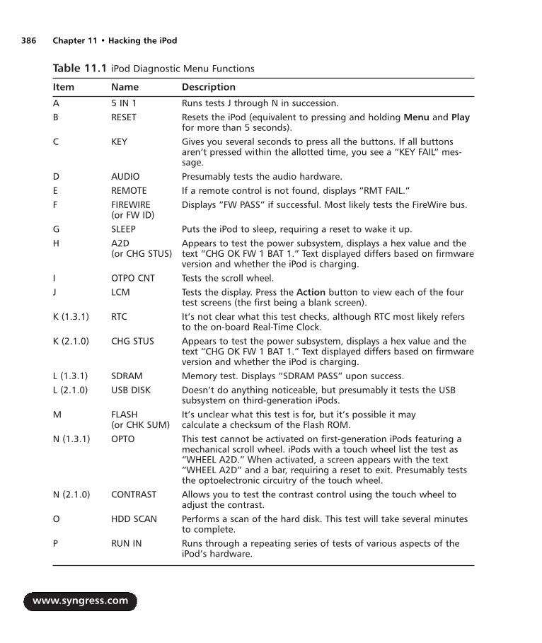
Table 11.1 iPod Diagnostic Menu Functions
Item Name Description
A 5 IN 1 Runs tests J through N in succession.B RESET Resets the iPod (equivalent to pressing and holding Menu and Play
for more than 5 seconds).C KEY Gives you several seconds to press all the buttons. If all buttons
aren’t pressed within the allotted time, you see a “KEY FAIL” mes-sage.
D AUDIO Presumably tests the audio hardware. E REMOTE If a remote control is not found, displays “RMT FAIL.”F FIREWIRE Displays “FW PASS” if successful. Most likely tests the FireWire bus.
(or FW ID)G SLEEP Puts the iPod to sleep, requiring a reset to wake it up.H A2D Appears to test the power subsystem, displays a hex value and the
(or CHG STUS) text “CHG OK FW 1 BAT 1.” Text displayed differs based on firmwareversion and whether the iPod is charging.
I OTPO CNT Tests the scroll wheel. J LCM Tests the display. Press the Action button to view each of the four
test screens (the first being a blank screen).K (1.3.1) RTC It’s not clear what this test checks, although RTC most likely refers
to the on-board Real-Time Clock.K (2.1.0) CHG STUS Appears to test the power subsystem, displays a hex value and the
text “CHG OK FW 1 BAT 1.” Text displayed differs based on firmwareversion and whether the iPod is charging.
L (1.3.1) SDRAM Memory test. Displays “SDRAM PASS” upon success.L (2.1.0) USB DISK Doesn’t do anything noticeable, but presumably it tests the USB
subsystem on third-generation iPods.M FLASH It’s unclear what this test is for, but it’s possible it may
(or CHK SUM) calculate a checksum of the Flash ROM.N (1.3.1) OPTO This test cannot be activated on first-generation iPods featuring a
mechanical scroll wheel. iPods with a touch wheel list the test as“WHEEL A2D.” When activated, a screen appears with the text“WHEEL A2D” and a bar, requiring a reset to exit. Presumably teststhe optoelectronic circuitry of the touch wheel.
N (2.1.0) CONTRAST Allows you to test the contrast control using the touch wheel toadjust the contrast.
O HDD SCAN Performs a scan of the hard disk. This test will take several minutesto complete.
P RUN IN Runs through a repeating series of tests of various aspects of theiPod’s hardware.
www.syngress.com
386 Chapter 11 • Hacking the iPod
287_HRD_HACK_11.qxd 1/13/04 7:45 PM Page 386
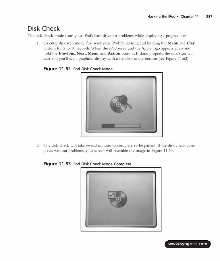
Disk CheckThe disk check mode scans your iPod’s hard drive for problems while displaying a progress bar.
1. To enter disk scan mode, first reset your iPod by pressing and holding the Menu and Playbuttons for 5 to 10 seconds. When the iPod resets and the Apple logo appears, press andhold the Previous, Next, Menu, and Action buttons. If done properly, the disk scan willstart and you’ll see a graphical display with a scrollbar at the bottom (see Figure 11.62).
2. The disk check will take several minutes to complete, so be patient. If the disk check com-pletes without problems, your screen will resemble the image in Figure 11.63.
www.syngress.com
Hacking the iPod • Chapter 11 387
Figure 11.62 iPod Disk Check Mode
Figure 11.63 iPod Disk Check Mode Complete
287_HRD_HACK_11.qxd 1/13/04 7:45 PM Page 387
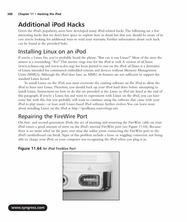
Additional iPod HacksGiven the iPod’s popularity, users have developed many iPod-related hacks.The following are a fewinteresting hacks that we don’t have space to explore here in detail but that you should be aware of incase you’re looking for additional ways to void your warranty. Further information about each hackcan be found at the provided links.
Installing Linux on an iPodIf you’re a Linux fan, you’ve probably heard the phrase,“But can it run Linux?” Most of the time theanswer is a resounding,“Yes!”This answer rings true for the iPod as well.A version of uClinux(www.uclinux.org and www.ucdot.org) has been ported to run on the iPod. uClinux is a derivativeof Linux intended for constrained embedded systems and devices without Memory ManagementUnits (MMUs).Although the iPod does have an MMU, its features are not sufficient to support thestandard Linux kernel.
To install Linux on the iPod, you must overwrite the existing software on the iPod to allow theiPod to boot into Linux.Therefore, you should back up your iPod hard drive before attempting toinstall Linux. Instructions on how to do this are provided at the Linux on iPod site listed at the end ofthis paragraph. If you’re a Linux fan and want to experiment with Linux on the iPod, you can havesome fun with this, but you probably will want to continue using the software that came with youriPod to play music—at least until Linux-based iPod software further evolves.You can learn moreabout installing Linux on the iPod at http://ipodlinux.sourceforge.net.
Repairing the FireWire PortOn first- and second-generation iPods, the act of inserting and removing the FireWire cable on youriPod causes a good amount of stress on the iPod’s internal FireWire port (see Figure 11.64). Becausethere is no strain relief on the port, over time the solder joints connecting the FireWire port to theiPod’s motherboard can break. Signs of this problem include a loose or wiggling connector, not beingable to charge your iPod, or your computer not recognizing the iPod when you plug it in.
www.syngress.com
388 Chapter 11 • Hacking the iPod
Figure 11.64 An iPod FireWire Port
287_HRD_HACK_11.qxd 1/13/04 7:45 PM Page 388

If you suspect your FireWire port might be damaged and you’re comfortable with soldering smalldevices, you can open your iPod and resolder the connections to the FireWire port yourself.You canalso apply some hot glue to the FireWire port to help provide some stress relief so this problem(hopefully) does not reoccur. If you’d prefer not to do this repair yourself, PDASmart (http://pdasmart.com/ipodpartscenter.htm) offers a mail-in service whereby they will fix theFireWire port for significantly less than Apple would charge for the same repair.
Scroll Wheel FixFirst-generation iPods feature a mechanical scroll wheel that spins around a center point, as opposedto later iPod models that use a solid-state touch wheel.The scroll wheel tends to become loose or“sloppy” with time, allowing it to spin more freely. Unfortunately, this can result in frequent andundesirable volume changes when you’re using your iPod, especially if you’re in motion. However,this problem can be solved with a small amount of effort.
1. This hack involves removing the scroll wheel and center button, preferably by using a pieceof masking (or similar) tape to lift up the wheel and button. (Do not use a knife to pry upthe wheel!) Under the scroll wheel is a small metal bearing that the wheel snaps onto,which allows it to spin in place (see Figure 11.65).
2. Once you have the device open, you can clean away any grease or debris from the bearingand then apply new grease. Be careful of petroleum-based products, however, since they candegrade plastics.
You can find more information on this hack at www.ipoding.com/modules.php?op=modload&name=News&file=article&sid=486.
www.syngress.com
Hacking the iPod • Chapter 11 389
Figure 11.65 iPod Scroll Wheel Internals
287_HRD_HACK_11.qxd 1/13/04 7:45 PM Page 389
iPod Resources on the WebA large number of Web sites have sprung up on which you can learn more about the iPod, buy var-ious iPod accessories and products, and discuss the iPod with other fans.The following is a short listof such sites; a quick search on Google will reveal many more:
iPod Home Page: www.apple.com/ipod This should be your first stop when you’relooking for iPod information. From here you can download the latest iPod software andbrowse through a wealth of information about the iPod and, of course, links to the AppleStore, where you can buy iPods and iPod accessories.
iTunes Home Page: www.apple.com/itunes No iPod is complete without iTunes,Apple’s free digital jukebox that is custom-tailored for the iPod. Versions for Macintosh andWindows computers are available. iTunes also provides you access to Apple’s iTunes MusicStore, allowing you to browse a large library of music that can be purchased and down-loaded to your computer online.
iPodLounge: www.ipodlounge.com If you’d like to keep up on the latest iPod news,the iPodLounge is a great place to start. Updated frequently with iPod-related news,iPodLounge also features original editorial content, reviews of iPod products, an informativeFAQ, active iPod forums, and much more.
iPod Hacks: www.ipodhacks.com iPod Hacks contains a variety of information aboutthe iPod, including hacks and mods as well as iPod-related software you can download.There’s also a forum where you can discuss the iPod with other iPod fans.
Everything iPod: www.everythingipod.com If you’re looking for iPod accessories, thissite has quite a bit to offer. Product categories include accessories, cables, cases, headphones,speakers, and more.
Laptops for Less: www.ipodbattery.com If you need a replacement battery for youriPod and don’t want to pay $99 for Apple’s iPod Battery Replacement Program, you canorder iPod batteries here.
PDASmart: www.pdasmart.com Another source for replacement iPod batteries,PDASmart also offers a mail-in service that is less expensive than Apple’s iPod BatteryReplacement Program.
www.syngress.com
390 Chapter 11 • Hacking the iPod
287_HRD_HACK_11.qxd 1/13/04 7:45 PM Page 390

Can You Hear MeNow? Nokia 6210Mobile PhoneModifications
Hacks in this Chapter:
Nokia 6210 LED Modification
Data Cabling Hacks
Other Hacks and Resources
Chapter 12
391
287_HRD_HACK_12.qxd 1/13/04 7:49 PM Page 391

IntroductionThe mobile phone is one of the most widespread, complex pieces of hardware around these days. Onone hand, mobile phones are advanced radios. On the other hand, they are miniature computers.Thefunctionality of the mobile phone is controlled by both the device hardware and its internalfirmware/software.Therefore, aside from real hardware hacks, we will also discuss some ways tomodify the software through the use of hardware aids.
For the description of the hacks in this chapter, we use the Nokia 6210 GSM mobile phone (seeFigure 12.1).This phone, introduced in 2001, was one of the first to support Internet browsingthrough Wireless Access Protocol (WAP).
Nokia is one of the best-known mobile phone manufacturers in the world.The Finnish companyoriginally started as a paper manufacturing company that moved from rubber products to power andtelecommunications to the company that now has between 40 and 50 percent of the mobile phonemarket. Since about 1984, Nokia has produced portable phones in many different models.
The first hack in this chapter is the modification of the backlight color of the mobile phone.Replacing the light-emitting diodes (LEDs) is within the realm of the hobbyist using a small sol-dering iron and a steady hand.
Next we will look at interfacing to your mobile phone through different types of data cables con-nected to your PC.The data cables open up a number of possibilities to interact with and modifyyour phone’s software.The type of cable used for Nokia phones depends on several things, such as the
www.syngress.com
392 Chapter 12 • Nokia 6210 Moblie Phone Modifications
Figure 12.1 The Nokia 6210
287_HRD_HACK_12.qxd 1/13/04 7:49 PM Page 392
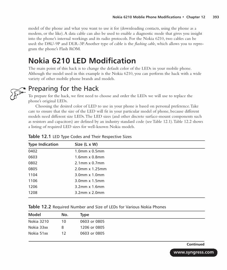
Nokia 6210 Moblie Phone Modifications • Chapter 12 393
model of the phone and what you want to use it for (downloading contacts, using the phone as amodem, or the like).A data cable can also be used to enable a diagnostic mode that gives you insightinto the phone’s internal workings and its radio protocols. For the Nokia 6210, two cables can beused: the DAU-9P and DLR-3P.Another type of cable is the flashing cable, which allows you to repro-gram the phone’s Flash ROM.
Nokia 6210 LED ModificationThe main point of this hack is to change the default color of the LEDs in your mobile phone.Although the model used in this example is the Nokia 6210, you can perform the hack with a widevariety of other mobile phone brands and models.
Preparing for the HackTo prepare for the hack, we first need to choose and order the LEDs we will use to replace thephone’s original LEDs.
Choosing the desired color of LED to use in your phone is based on personal preference.Takecare to ensure that the size of the LED will fit in your particular model of phone, because differentmodels need different size LEDs.The LED sizes (and other discrete surface-mount components suchas resistors and capacitors) are defined by an industry standard code (see Table 12.1).Table 12.2 showsa listing of required LED sizes for well-known Nokia models.
Table 12.1 LED Type Codes and Their Respective Sizes
Type Indication Size (L x W)
0402 1.0mm x 0.5mm0603 1.6mm x 0.8mm0802 2.1mm x 0.7mm0805 2.0mm x 1.25mm1104 3.0mm x 1.0mm1106 3.0mm x 1.5mm1206 3.2mm x 1.6mm1208 3.2mm x 2.0mm
Table 12.2 Required Number and Size of LEDs for Various Nokia Phones
Model No. Type
Nokia 3210 10 0603 or 0805Nokia 33xx 8 1206 or 0805 Nokia 51xx 12 0603 or 0805
www.syngress.com
Continued
287_HRD_HACK_12.qxd 1/13/04 7:49 PM Page 393

Table 12.2 Required Number and Size of LEDs for Various Nokia Phones
Model No. Type
Nokia 5210 11 0603 Nokia 5510 8 1206 or 0805 Nokia 61xx 12 0603 or 0805 Nokia 62xx/63xx 10 1206 or 0805 Nokia 71xx 4 1206
6 0603 or 0805 Nokia 82xx 12 0603 Nokia 83xx 10 0603 Nokia 8810 12 0603 Nokia 8850/90 14 or 16 0603
Figure 12.2 shows a drawing of a surface-mount LED. On the backside of the components, asymbol, dot, or other marking is used to help distinguish between the anode and cathode of thediode. In the same figure you can see the schematic symbol for an LED.
As shown in Table 12.2, the Nokia 6210 requires 10 LEDs of the type 0805 or 1206. In this case,we purchased ultra-bright blue 0805 LEDs (see Figure 12.3) from a local electronics store.This hackis simple in nature but serves as great practice for your soldering skills.
www.syngress.com
394 Chapter 12 • Nokia 6210 Moblie Phone Modifications
Figure 12.2 Schematic Symbol and Physical Outline of an LED
anode
cathode
T
287_HRD_HACK_12.qxd 1/13/04 7:49 PM Page 394
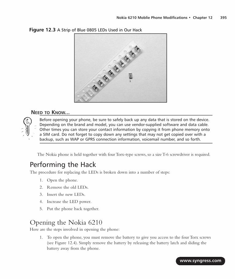
Nokia 6210 Moblie Phone Modifications • Chapter 12 395
NEED TO KNOW...Before opening your phone, be sure to safely back up any data that is stored on the device.Depending on the brand and model, you can use vendor-supplied software and data cable.Other times you can store your contact information by copying it from phone memory ontoa SIM card. Do not forget to copy down any settings that may not get copied over with abackup, such as WAP or GPRS connection information, voicemail number, and so forth.
The Nokia phone is held together with four Torx-type screws, so a size T-6 screwdriver is required.
Performing the HackThe procedure for replacing the LEDs is broken down into a number of steps:
1. Open the phone.
2. Remove the old LEDs.
3. Insert the new LEDs.
4. Increase the LED power.
5. Put the phone back together.
Opening the Nokia 6210Here are the steps involved in opening the phone:
1. To open the phone, you must remove the battery to give you access to the four Torx screws(see Figure 12.4). Simply remove the battery by releasing the battery latch and sliding thebattery away from the phone.
www.syngress.com
Figure 12.3 A Strip of Blue 0805 LEDs Used in Our Hack
287_HRD_HACK_12.qxd 1/13/04 7:49 PM Page 395

2. After removing the screws, the front and back halves of the phone are still held tightly toeach other.This is due to five clips that are part of the plastic housing. By inserting a smallscrewdriver at the correct positions, you can create enough room to slowly open the phonefurther (see Figure 12.5 and 12.6).
3. Although the phone is almost open, one more step is required. Slowly move the front andback parts of the housing sideways while feeling for the release of the clips at the top (seeFigure 12.7).The three top clips are connected to the front case and can take a bit of workto release. Never force this process or you may damage the clips.
www.syngress.com
396 Chapter 12 • Nokia 6210 Moblie Phone Modifications
Figure 12.4 The Back of the Nokia 6210 with Battery Removed; the Four Torx Screws Are Visible
Figure 12.5 Step 1: Releasing the PlasticHousing Clips from One Side of the Phone
Figure 12.6 Step 2: Releasing the PlasticHousing Clips from the Other Side of thePhone
287_HRD_HACK_12.qxd 1/13/04 7:49 PM Page 396

4. With the phone finally open, you will be left with two pieces: a plastic back housing andthe front housing containing the PCB (see Figure 12.8).As you can see, most of the phone’scircuitry is covered by metal shielding plates. With radio equipment, these shielding platesare important to reduce electrical interference.
5. The PCB is attached to the front side of the phone with a single Torx screw, which alsoattaches to the antenna.This part should be removed as shown in Figure 12.9.
www.syngress.com
Nokia 6210 Moblie Phone Modifications • Chapter 12 397
Figure 12.7 Releasing the Top Clips
Figure 12.8 The Opened Nokia 6210
287_HRD_HACK_12.qxd 1/13/04 7:49 PM Page 397
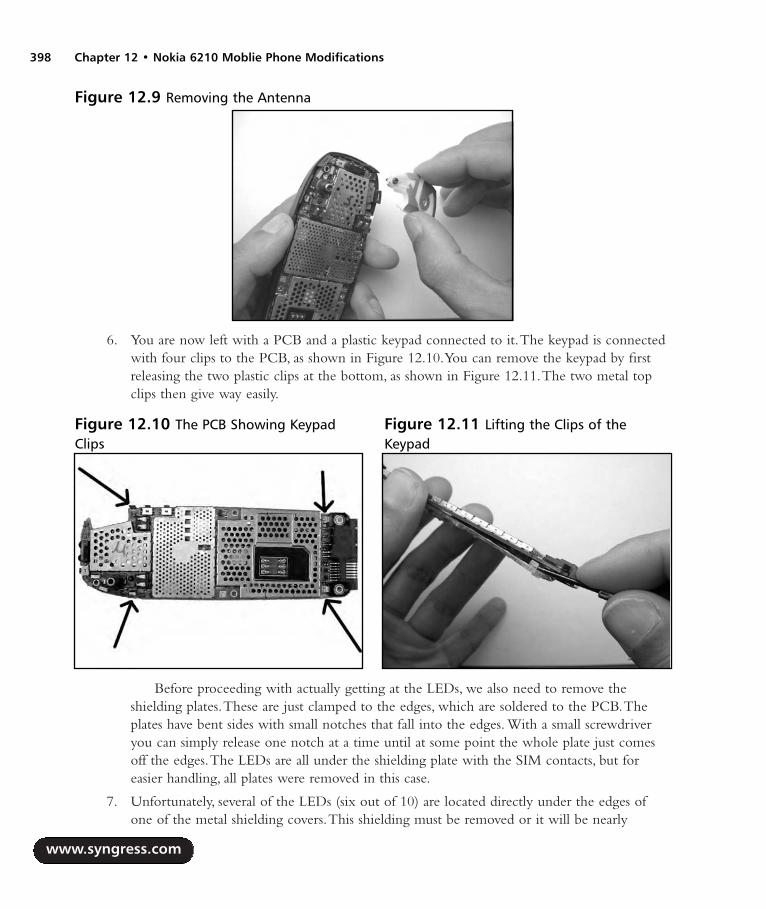
6. You are now left with a PCB and a plastic keypad connected to it.The keypad is connectedwith four clips to the PCB, as shown in Figure 12.10.You can remove the keypad by firstreleasing the two plastic clips at the bottom, as shown in Figure 12.11.The two metal topclips then give way easily.
Before proceeding with actually getting at the LEDs, we also need to remove theshielding plates.These are just clamped to the edges, which are soldered to the PCB.Theplates have bent sides with small notches that fall into the edges. With a small screwdriveryou can simply release one notch at a time until at some point the whole plate just comesoff the edges.The LEDs are all under the shielding plate with the SIM contacts, but foreasier handling, all plates were removed in this case.
7. Unfortunately, several of the LEDs (six out of 10) are located directly under the edges ofone of the metal shielding covers.This shielding must be removed or it will be nearly
www.syngress.com
398 Chapter 12 • Nokia 6210 Moblie Phone Modifications
Figure 12.9 Removing the Antenna
Figure 12.10 The PCB Showing KeypadClips
Figure 12.11 Lifting the Clips of theKeypad
287_HRD_HACK_12.qxd 1/13/04 7:49 PM Page 398

impossible to remove the old LEDs and solder in the new ones. Luckily, the shielding can beremoved fairly easily. In Figure 12.12, you can see how to remove the edges with two simplecuts at each of the corners. Repeat this process for the bottom edge that covers another twoLEDs. Next, slowly move the edge back and forth with a pair of pliers until the solder jointgives way, allowing you to easily pull the edge loose (see Figure 12.13).
9. The metal shield needs to be modified slightly to allow it to be safely reconnected to thephone after the hack. Because the edges of the shield have been clipped off as described,there is a risk that the shield will short-circuit with other components on the PCB.Therefore, simply use the pliers to cut away the small clips around the perimeter of themetal shield (see Figure 12.14).This will ensure that the shield will not come into contactwith any components.
www.syngress.com
Nokia 6210 Moblie Phone Modifications • Chapter 12 399
Figure 12.12 Removing the Edges of theMetal Shielding
Figure 12.13 Successful Removal of theMetal Shield Edges
Figure 12.14 Removing the Clips from the Perimeter of the Metal Shield
287_HRD_HACK_12.qxd 1/13/04 7:49 PM Page 399

Removing the Old LEDsBefore continuing with the hack, take care to note the orientation of the original LEDs.The newLEDs should be arranged in the exact same configuration or else they will not work.Take a picture ofyour circuit board or sketch out the LED configuration of your particular phone. Figure 12.15 showsa detailed picture of the LED locations and orientation of the Nokia 6210.Also note that the LEDsare shining to the other side of the PCB through a hole. Figure 12.15 shows the side where the LEDsare attached, but they shine through the other side.
1. Now it is time to tackle the desoldering of the LEDs.This requires a soldering iron with avery small tip. Using a small screwdriver or toothpick, gently push on the backside of thePCB while applying heat to the edges of the LED (see Figure 12.16).
WARNING: HARDWARE HARM
Use a small amount of pressure when removing the LEDs. Pushing a little too hard with thesoldering iron can rip the whole LED from the board, possibly causing irreparable damage tothe PCB. Also, be sure not to bend the circuit board, since doing so can cause cracks in thetraces and will render your phone useless.
www.syngress.com
400 Chapter 12 • Nokia 6210 Moblie Phone Modifications
Figure 12.15 Nokia 6210 LEDs; Note the Orientation Marks
287_HRD_HACK_12.qxd 1/13/04 7:49 PM Page 400
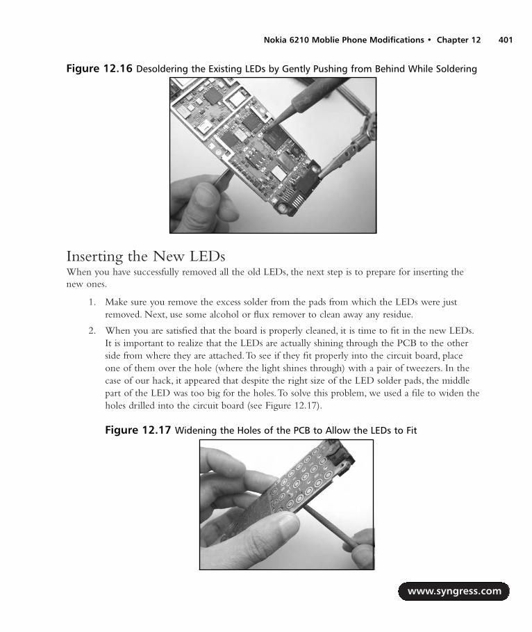
Inserting the New LEDsWhen you have successfully removed all the old LEDs, the next step is to prepare for inserting thenew ones.
1. Make sure you remove the excess solder from the pads from which the LEDs were justremoved. Next, use some alcohol or flux remover to clean away any residue.
2. When you are satisfied that the board is properly cleaned, it is time to fit in the new LEDs.It is important to realize that the LEDs are actually shining through the PCB to the otherside from where they are attached.To see if they fit properly into the circuit board, placeone of them over the hole (where the light shines through) with a pair of tweezers. In thecase of our hack, it appeared that despite the right size of the LED solder pads, the middlepart of the LED was too big for the holes.To solve this problem, we used a file to widen theholes drilled into the circuit board (see Figure 12.17).
www.syngress.com
Nokia 6210 Moblie Phone Modifications • Chapter 12 401
Figure 12.16 Desoldering the Existing LEDs by Gently Pushing from Behind While Soldering
Figure 12.17 Widening the Holes of the PCB to Allow the LEDs to Fit
287_HRD_HACK_12.qxd 1/13/04 7:50 PM Page 401

3. Once the PCB has been modified to fit the new LEDs, it is time to solder them into place.To do this, first retrieve your notes on the orientation of the original LEDs. Position thePCB horizontally so the LEDs will stay put as you are soldering them in. When solderingthe LEDs, apply just enough heat to provide a good solder joint.Too much heat maydamage the LED.As shown in Figure 12.18, a pair of tweezers can help hold the LED inplace while you solder it.
Increasing the LED PowerDepending on the type of phone and the type of LED used, the intensity of the replacement LEDmay be too bright or too dim.This is due to the forward voltage, current, and efficiency of the LED.To control the current going to the LEDs, current-limiting resistors are added in series. (You can findmore information on electronic theory in Chapter 2,“Electrical Engineering Basics.”) In the case ofthe Nokia 6210, the schematic of how the LEDs are connected is shown in Figure 12.22. In theschematic, two groups of LEDs can be distinguished. On the left is a group of six LEDs for thekeypad; on the right is a group of four LEDs for the display.
To increase the voltage drop over the LEDs, we need to change the total resistor value (combinedvalue of two parallel resistors) at the top of the schematic to a value of 2.2 ohms for the keypad LEDsand 3.3 ohms for the display LEDs. However, because of the low values of these resistors, the room intolerances in general and the fact that it is much more convenient, we decided to use jumpers directlyto the 3.6 volts instead.To achieve this, we only need to short one resistor for both the display andkeypad LEDs. When we examine the PCB for the phone, we can find the resistors on the side in thesame area as the LEDs.The exact location of the resistors is shown in Figure 12.19. We can do this bysoldering a little piece of wire over the two ends of the resistor. Due to the size, often a single drop ofsolder or a single strand of a wire will do the job as well. Be careful not to heat the resistor too muchor else it might come off the board completely.
www.syngress.com
402 Chapter 12 • Nokia 6210 Moblie Phone Modifications
Figure 12.18 Soldering the New LEDs into Place
287_HRD_HACK_12.qxd 1/13/04 7:50 PM Page 402
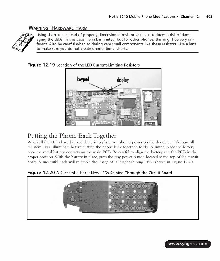
WARNING: HARDWARE HARM
Using shortcuts instead of properly dimensioned resistor values introduces a risk of dam-aging the LEDs. In this case the risk is limited, but for other phones, this might be very dif-ferent. Also be careful when soldering very small components like these resistors. Use a lensto make sure you do not create unintentional shorts.
Putting the Phone Back TogetherWhen all the LEDs have been soldered into place, you should power on the device to make sure allthe new LEDs illuminate before putting the phone back together.To do so, simply place the batteryonto the metal battery contacts on the main PCB. Be careful to align the battery and the PCB in theproper position. With the battery in place, press the tiny power button located at the top of the circuitboard.A successful hack will resemble the image of 10 bright shining LEDs shown in Figure 12.20.
www.syngress.com
Nokia 6210 Moblie Phone Modifications • Chapter 12 403
Figure 12.19 Location of the LED Current-Limiting Resistors
Figure 12.20 A Successful Hack: New LEDs Shining Through the Circuit Board
287_HRD_HACK_12.qxd 1/13/04 7:50 PM Page 403

The process of putting the phone backtogether is the exact opposite of opening thephone (described at the beginning of thischapter):
1. Put all the shielding plates back inplace. Make sure the clips of theshielding plate do not short-circuitwith any components on the PCB.Next, attach the keypad back ontothe PCB. Be sure that the contactsat the top of the keypad make goodcontact with the copper areas onthe PCB. Replace the keypad coverand fit the PCB back into the frontside of the phone’s plastic housing.
2. On the opposite side, connect theantenna back to the PCB andsecure with the Torx screw. Finally,connect the bottom side of thephone’s plastic housing and pushtogether. Make sure you hear anaudible click as the clasps connectbetween the top and bottom piecesof the housing. Screw in the four Torx screws and replace the battery.
If everything went well, when you turn the phone on, you should have a new backlight color foryour display, as shown in Figure 12.21!
Under the Hood: How the Hack WorksA schematic diagram of how the LEDs are connected into the phone is shown in Figure 12.22.TheLEDs are designated as D1 through D10, the current-limiting resistors are R1 through R4, and thetransistors are Q1 and Q2.The transistors are used as switches to allow current to flow into thediodes, thus illuminating the lights.The hack is very simple, due to the fact that all we are doing isreplacing the LEDs on the circuit board.
The current flow into the LEDs needs to be adjusted accordingly to meet your desired bright-ness.This is done by changing the value of the current-limiting resistors, which can be calculatedusing Ohm’s Law. For the Nokia 6210, the VCC supply voltage is 3.6V. Each group of LEDs is inparallel (one group of six and the other group of four), so the current flowing through the limitingresistors will be evenly distributed through the LEDs. So, assuming a typical forward current of 7mAthrough each LED (which will usually produce a not-too-bright illumination) and a forward voltage
www.syngress.com
404 Chapter 12 • Nokia 6210 Moblie Phone Modifications
Figure 12.21 A Successful Hack: The FinishedPhone with New Lighting
287_HRD_HACK_12.qxd 1/13/04 7:50 PM Page 404

of 3.5V for a blue LED (a red LED typically has a forward voltage of 2V and a green LED has a for-ward voltage of 2.2V—different-colored LEDs have different voltage drops, so it is not often that youcan just replace one color LED with another and assume you will have the same brightness and notdamage the part), the resistance is calculated as follows:
R = V / I
where:
R = resistance (ohm)
V = voltage (V)
I = current (A)
Group 1: R = Effective resistance of R1 and R2 = (VCC – VF) / IF = (3.6 – 3.5) / (0.007 x 6) = 2.38 ohms
The closest standard resistor value is 2.2 ohms, 5% tolerance.
Group 2: R = Effective resistance of R3 and R4 = (VCC – VF) / IF = (3.6 – 3.5) / (0.007 x 4) = 3.57 ohms
The closest standard resistor value is 3.3 ohms, 5% tolerance.
As you can see from these calculations, the resulting resistor values are very small. For this reasonand because manufacturing tolerances generally allow for some additional load, we decided to replacethe resistors with jumpers (see Figure 12.22).This will result in slightly brighter LEDs.
www.syngress.com
Nokia 6210 Moblie Phone Modifications • Chapter 12 405
Figure 12.22 The Schematic for the Lighting in a Nokia Phone, Including the Jumpers
D8D7D3
R1
D4
Q1
PNP BCE
D10
R2
D5
R3
D1 D9D6
Q2
PNP BCE
R4
D2
VCC
ShortcutShortcut
287_HRD_HACK_12.qxd 1/13/04 7:50 PM Page 405

Data Cabling HacksAs was mentioned at the start of this chapter, most hacks on mobile phones involve software hacksinstead of hardware hacks.The very specific hardware combined with the surface-mount technologiesmakes it difficult to perform many hardware-based hacks.This section aims to give some insight inthe hacks involved on the software level.Again we use the Nokia phone as an example, but manyother brands of phone present similar possibilities.
Data cables are used to interface a PC with special features of the cell phone.The cables are eitherstandard cables produced by the manufacturer (for data synchronization, backups, loading new ringtones, and so on) or a homebrew cable made by a hardware hacker.The data cables open up anumber of possibilities to interact with and modify the software of your phone.A data cable can alsobe used to enable a diagnostic mode that gives you insight into the phone’s internal workings and itsradio protocols.As mentioned earlier, another type of cable is the flashing cable, which allows you toreprogram the phone’s Flash ROM.
Before we take a closer look at cables, we need to clarify something about the phone models byNokia. Over time Nokia has produced a wide range of phones, each with a variety of features andoptions. However, many of the phones also have features in common, such as the way the underlyingsoftware operates.
The Nokia 6210 belongs to the DCT-3 generation of Nokia phone. Newer models of Nokiaphones manufactured in and after 2002 belong to the DCT-4 generation.Table 12.3 shows many of theNokia DCT-3 generation phones.The cable information that we discuss in this chapter is relevant forthe DCT-3 series. DCT-4 has some improvements in the security mechanisms surrounding softwareaccess and hacking and will not be discussed here, though much information is available on the Web.
Table 12.3 Listing of the Most Common Nokia DCT-3 Models
Model Nokia Type
2100 NAM-23210 NSE-83310 NHM-53315 NHM-53330 NHM-63350 NHM-93410 NHM-23610 NAM-13810 NHE-95110 NSE-15110i NSE-25210 NSM-55510 NPM-5
www.syngress.com
406 Chapter 12 • Nokia 6210 Moblie Phone Modifications
Continued
287_HRD_HACK_12.qxd 1/13/04 7:50 PM Page 406

Table 12.3 Listing of the Most Common Nokia DCT-3 Models
Model Nokia Type
6090 NME-36110 NSE-36110i NSE-3i6150 NSM-16210 NPE-36250 NHM-37110 NSE-58210 NSM-38250 NSM-28810 NSE-68850 NSM-28855 NSM-49000 RAE-1N9000i RAE-49110 RAE-29110i RAE-2i
Data CablesData cables are logically divided into two parts:
The physical cable
The protocol transmitted over the cable
Nokia phones use and understand two separate protocols:
MBUS
FBUS
MBUS is an older and slower protocol. It uses a single pin to transmit and receive serial data andone pin for ground. It is a half-duplex protocol at 9600bps.The FBUS protocol is newer and fasterand uses two pins to transmit full-duplex serial data at 115.2kbps and one pin for ground.The pro-tocol format between MBUS and FBUS varies. FBUS has been reverse-engineered by several groupsand people over time.The most well known open-source implementations of these protocols areGnokii (www.gnokii.org) and Gammu (www.mwiacek.com/gsm/gammu/gammu.html).
The physical cable that is used to connect the phone to the serial port of the PC contains activeparts that usually serve level-conversion purposes but sometimes contain more complex logic. For the
www.syngress.com
Nokia 6210 Moblie Phone Modifications • Chapter 12 407
287_HRD_HACK_12.qxd 1/13/04 7:50 PM Page 407
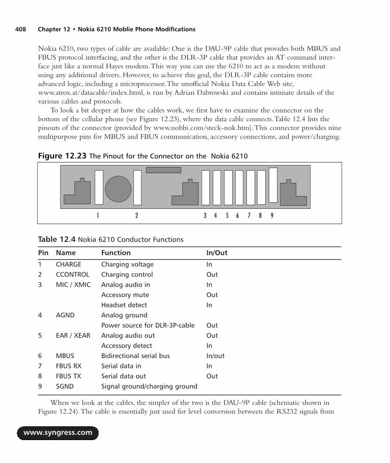
Nokia 6210, two types of cable are available: One is the DAU-9P cable that provides both MBUS andFBUS protocol interfacing, and the other is the DLR-3P cable that provides an AT command inter-face just like a normal Hayes modem.This way you can use the 6210 to act as a modem withoutusing any additional drivers. However, to achieve this goal, the DLR-3P cable contains moreadvanced logic, including a microprocessor.The unofficial Nokia Data Cable Web site,www.atrox.at/datacable/index.html, is run by Adrian Dabrowski and contains intimate details of thevarious cables and protocols.
To look a bit deeper at how the cables work, we first have to examine the connector on thebottom of the cellular phone (see Figure 12.23), where the data cable connects.Table 12.4 lists thepinouts of the connector (provided by www.nobbi.com/steck-nok.htm).This connector provides ninemultipurpose pins for MBUS and FBUS communication, accessory connections, and power/charging.
Table 12.4 Nokia 6210 Conductor Functions
Pin Name Function In/Out
1 CHARGE Charging voltage In2 CCONTROL Charging control Out3 MIC / XMIC Analog audio in In
Accessory mute OutHeadset detect In
4 AGND Analog groundPower source for DLR-3P-cable Out
5 EAR / XEAR Analog audio out OutAccessory detect In
6 MBUS Bidirectional serial bus In/out7 FBUS RX Serial data in In8 FBUS TX Serial data out Out9 SGND Signal ground/charging ground
When we look at the cables, the simpler of the two is the DAU-9P cable (schematic shown inFigure 12.24).The cable is essentially just used for level conversion between the RS232 signals from
www.syngress.com
408 Chapter 12 • Nokia 6210 Moblie Phone Modifications
Figure 12.23 The Pinout for the Connector on the Nokia 6210
1 2 3 4 5 6 7 8 9
287_HRD_HACK_12.qxd 1/13/04 7:50 PM Page 408

the PC and the signals for the Nokia phone.The Maxim MAX3232 device is a standard RS232 “levelshifter” to bring the RS232 levels to voltages that the Nokia can handle.The circuitry in the cable isalso powered through the RS232 port, passing voltages from the port into a 78L02 voltage regulatorto create a 2.6V VCC.
The main difference between the DLR-3P and DAU-9P cables is that the DLR-3P actively per-forms part of the FBUS protocol handshake within the cable (schematic shown in Figure 12.25). Bypulling pin 3 of the phone to a logic LOW level, it signals the phone to apply power to pin 4.Thispower is then used to power the circuitry in the cable. Next, the phone begins communicating usingthe MBUS protocol, and the Microchip PIC16F84 processor receives the commands and respondswith an acknowledgment. When the phone receives the acknowledgments from the PIC, it switchesto a mode in which it accepts normal Hayes-style AT commands from a PC on the FBUS lines.
www.syngress.com
Nokia 6210 Moblie Phone Modifications • Chapter 12 409
Figure 12.24 Schematic for a DAU-9P Cable by Adrian Dabrowski, www.atrox.at/datacable
VCC
VCC
D3 BAT41JP1MBUS Jumper
1 2
U278L02
1 3
2
IN OUT
GND
C50.1uF
C2 0.1uF C3 0.1uF
C4 0.1uF
U1MAX3232
15
16
138
1011
1
3
4
5
26
129
147
GND
VCC
R1INR2IN
T2INT1IN
C1+
C1-
C2+
C2-
V+V-
R1OUTR2OUT
T1OUTT2OUT
DB9F
594837261
123456789
C60.1uF
1N4148D1
1N4148D2
C1 0.1uF
To Nokia51xx/61xx
Figure 12.25 Schematic for a DLR-3P Cable by Adrian Dabrowski, www.atrox.at/datacable
VCC
VCC
VCC
100
DB9F
594837261
Y 18MHz
U2MAX3241
1314
19
22
2324
25
2628
4
9101112
1
227
3
T2INT1IN
R1OUT
SHDN
ENC1-
GND
VCCC1+
R1IN
T1OUTT2OUTT3OUTT3IN
C2+
C2-V+
V-
U1PIC16F84
1
2
3
4
5
10
11
14
15
16
17
18
RA2
RA3
RA4
MCLR
GND
RB4
RB5
VDD
OSC1
OSC2
RA0
RA1
1 2 3 4 5 6 7 8 9
C1 30pF
C2 30pF
D1 BAT41
1k 1k
C4 0.1uF
C3 0.1uF
C5 0.1uF
1k15k
C6 0.1uF
To Nokia 6210/7100
287_HRD_HACK_12.qxd 1/13/04 7:50 PM Page 409

Flashing CablesFlashing cables are used for reprogramming the Flash ROM device inside the phone.The cables areprimarily used by the manufacturer or service personnel to update the phone’s software/firmware.The flash cable can also provide you with calibration data and other debugging information.AlthoughNokia does not endorse using a flash cable on your phone, knowledge about how this process worksis now public.
The flash cables we discuss in this chapter are meant for the DCT-3 generation of phones.TheDCT-4 generation incorporates new encryption methods and code signing to make modifications tothe Flash ROM more challenging; they aren’t discussed here.
The flash cable uses the same connector interface as shown in Figure 12.23. However, the pins areused in a different way compared to the “regular” DAU-9P and DLR-3P cables.The protocol used tocommunicate between the phone and the PC is similar to the I2C serial protocol. Because timing iscritical with this protocol, the serial port cannot be used. Instead, these cables are controlled from thePC’s parallel port, which is more suitable for timing-sensitive applications.The schematic for a DCT-3flash cable is shown in Figure 12.26. Software can be found on Dejan Kaljevic’s Web site athttp://users.net.yu/~dejan.
On power up, the Nokia phone performs a check of the MBUS line. When MBUS is pulled to alogic LOW level instead of following the normal path to your phone, the phone enters a bootstrapmode in which it accepts code transmitted from the PC.The flashing code sent to the phone is essen-tially a miniature operating system that can report the status of the phone, read contents of the Flashmemory, and erase or write Flash memory blocks.
www.syngress.com
410 Chapter 12 • Nokia 6210 Moblie Phone Modifications
Figure 12.26 Schematic for a DCT-3 Flash Cable by Dejan Kaljevic,http://users.net.yu/~dejan
DB25M
13251224112310229218207196185174163152141 2 x 1N4148
5 6
0.1uF 1004.7k
74HC14
1 2
7
1312
14
3 4
FBUS TX
VPP
BTEMP
FBUS RX
MBUS
GND
To PC Parallel Port
To Nokia Phone
287_HRD_HACK_12.qxd 1/13/04 7:50 PM Page 410

Net MonitorOne of the interesting features built into Nokia DCT-3 phones is the Net Monitor mode.This is adiagnostic facility that allows you to test and monitor several aspects of the phone.The Net Monitorfunctionality has been removed from DCT-4 version phones.
The Net Monitor menu allows you to examine the internal functionality of your phone and theGSM network is it connected to.You can even modify the way it operates on the GSM network.
To enable the Net Monitor, a data cable and special software are used. Several tools have beencreated for this purpose, and most can be found on the Internet by searching for terms like “N-Monitor” and “Net Monitor Activator.” One of the best-known tools is Logo Manager (a demo ver-sion is available at www.logomanager.co.uk).
The software sends a special FBUS security command to the phone, which enables a new menuitem on the phone. Once you do this, when cycling through the menus on your phone, you shouldcome across a display like the one shown in Figure 12.27. From this menu we can now start to explorethe different options.
The options in the Net Monitor are called Tests and are each identified by a number.When wepress Select in the menu, we are presented a screen in which to enter a test number (see Figure 12.28).
Enter test number 01 and press OK. We are now presented with a screen showing blocks of let-ters and numbers (see Figure 12.29).
WARNING: HARDWARE HARM
Do not enter arbitrary test numbers in the test entry menu unless you know exactly what thetest is for. Some functionality within the tests may alter the behavior of your phone, pre-venting it from working properly. Two of the most extensive resources of Net Monitor testscan be found at www.mwiacek.com/gsm/netmon/faq_net0.htm and www.nobbi.com/down-load/nmmanual.pdf.
www.syngress.com
Nokia 6210 Moblie Phone Modifications • Chapter 12 411
Figure 12.27 The Net Monitor MenuFigure 12.28 Entering the Desired TestNumber
287_HRD_HACK_12.qxd 1/13/04 7:50 PM Page 411

At the top left of the display, the test number is shown.The other numbers on the display giveinformation related to the current link with the GSM network.This link is established with a basestation, and the display informs us that it is currently on the Common Control Channel, or CCCH.Other information is identified as follows (from http://home.tiscali.cz:8080/ca517880/netmon_0.8.doc):
++++++++++++++ ##############
+abbb ccc ddd+ #CH RxL TxPwr #
+ e ff g mmmm+ #TS TA RQ RLT #
+ nnn ppp+ # C1 C2 #
+ oooo + # CHT #
++++++++++++++ ##############
a H, if carrier numbers are scrolled when hopping is on. Otherwise ' '.
bbb When mobile is on TCH:
DCH carrier number in decimal.
When mobile is NOT on TCH:
CH means carrier number in decimal.
If hopping is on, used channels are scrolled
when display is updated.
ccc rx level in dBm, minus sign not shown if <=-100
ddd tx power level. If transmitter is on, symbol *
is shown in front of the power level value.
e Time Slot, range is 0 - 7
www.syngress.com
412 Chapter 12 • Nokia 6210 Moblie Phone Modifications
Figure 12.29 Test 01: Showing the Phone’s GSM Parameters
287_HRD_HACK_12.qxd 1/13/04 7:50 PM Page 412

ff Timing advance, range is 0 – 63
g rx quality (sub), range is 0 - 7
mmmm Radio Link Timeout value. If value is negative, 0 is shown.
Maximum value is 64. When mobile is NOT on TCH then xx is shown.
nnn value of the path loss criterium (C1). Range is -99 - 999.
oooo type of current channel:
THR0 : TCH HR subchannel 0
THR1 : TCH HR subchannel 1
TFR : TCH FR
TEFR : TCH EFR
F144 : TCH FR data channel, speed 14.4 kbps
F96 : TCH FR data channel, speed 9.6 kbps
F72 : TCH FR data channel, speed 7.2 kbps
F48 : TCH FR data channel, speed 4.8 kbps
F24 : TCH FR data channel, speed 2.4 kbps
H480 : TCH HR data channel, speed 4.8 kbps, subch 0
H481 : TCH HR data channel, speed 4.8 kbps, subch 1
H240 : TCH HR data channel, speed 2.4 kbps, subch 0
H241 : TCH HR data channel, speed 2.4 kbps, subch 1
FA : TCH FR signalling only (FACCH) channel
FAH0 : TCH HR signalling only (FACCH) channel, subch 0
FAH1 : TCH HR signalling only (FACCH) channel, subch 1
SDCC : SDCCH
AGCH : AGCH
CCCH : CCCH
CBCH : CCCH and cell broadcast receiving on
BCCH : BCCH
SEAR : SEARCH
NSPS : MS is in No Serv Power Save state
ppp value of the cell reselection criterium (C2).
Range is -99 - 999. If phone is phase 1 then C1 value is shown.
www.syngress.com
Nokia 6210 Moblie Phone Modifications • Chapter 12 413
287_HRD_HACK_12.qxd 1/13/04 7:50 PM Page 413

To show that this is actual information being displayed, Figure 12.30 shows the same test butactually engaged to another mobile phone.The transmitter power level is now shown, timing infor-mation is given, and a different type of channel is shown.
One of the cool tricks with the Net Monitor is that you can also modify the phone’s behaviorthrough the tests. For example, it is possible to have the phone only use so-called “barred base sta-tions.”These are base stations that the operator (the cell phone carrier) does not want the phone touse.This could be for all kinds of reasons such as maintenance or testing.The base station is flaggedby a barring flag that the mobile phone can check and normally honors. By using test 19 on thephone, we can change the phone’s behavior to reverse the effect of the flag and only use barred basestations (CELL BARR REVERSE) or to ignore the flag and use both normal and barred base sta-tions (CELL BARR DISCARD). When we enter test 19 in the entry menu twice in a row, we seethe display in Figure 12.31.
www.syngress.com
414 Chapter 12 • Nokia 6210 Moblie Phone Modifications
Figure 12.30 Test 01: Information Displayed When the Phone Is Engaged in a Call
Figure 12.31 Test 19: Ignoring Barred Base Stations
287_HRD_HACK_12.qxd 1/13/04 7:50 PM Page 414

To inspect if any barred base stations are nearby, we can use tests 03, 04, and 05, which list infor-mation on other base stations within the phone’s vicinity.A mobile phone continuously monitors formore cells than the one it is currently connected to in order to switch to a new cell when receptionfalls below a certain level. In Figure 12.32, you can see neighboring cells, of which one is a barred cellidentified by a B instead of N, for normal base stations.
There are many other interesting test modes within the Net Monitor:
Test 11 Display network parameters.
Test 20 Display the phone’s charging state.
Test 23 Display battery information.
Test 88 Display current MCU and DSP software/firmware versions.
Test 241 Disable the Net Monitor menu. (You will need the special enabling software toturn it on again.)
Test 242 Only allow tests 01 through 19.
Other Hacks and ResourcesThis chapter only showed a small portion of the possible hacks and experiments you can performwith your mobile phone. Visit the resources below for more ideas and hacks:
NUUKIAWORLD, www.panuworld.net/nuukiaworld/index.htm One of the bestNokia-related hardware-hacking sites.
Embedtronics, www.embedtronics.com/nokia/fbus.html Another hardware-hackingsite with details of the FBUS and SMS protocols.
www.syngress.com
Nokia 6210 Moblie Phone Modifications • Chapter 12 415
Figure 12.32 Test 03: Base Stations Within the Phone’s Vicinity
287_HRD_HACK_12.qxd 1/13/04 7:50 PM Page 415

JBPhonetech, www.burrillj.fsnet.co.uk LED backlight changing supply and fitting ser-vice.Also provides details of do-it-yourself LED modifications.
Nobbi’s GSM Site, www.nobbi.com/monitor/index_en.htm Provides detailed infor-mation and software to enable Net Monitor mode.
Project Blacksphere, www.blacksphere.tk Information database and community ofdiehard mobile phone hardware hackers and reverse engineers; lots of software tools anddetailed information.
MADos, http://gsmfreeboard.eu.org, www.nokiaport.de/RE,http://nokiafree.org/forums A completely new operating system created for the Nokiaphone. Information can be found in the listed forums.
www.syngress.com
416 Chapter 12 • Nokia 6210 Moblie Phone Modifications
287_HRD_HACK_12.qxd 1/13/04 7:50 PM Page 416

Upgrading Memoryon Palm Devices
Hacks in this Chapter:
Hacking the Pilot 1000 and Pilot 5000
Hacking the PalmPilot Professional andPalmPilot Personal
Hacking the Palm m505
Technical Information
Palm Links on the Web
Chapter 13
417
287_HRD_HACK_13.qxd 1/13/04 7:54 PM Page 417

IntroductionWhether you are walking down a busy city street or eating at restaurant in a small town, it is impossibleto look around without seeing someone using a personal digital assistant, or PDA. But it wasn’t alwayslike this.At one time, a PDA user would get stares and hear chuckles from nosey outsiders wonderingwhat this thing was, this high-tech gadget like something out of Star Trek, that they were using.
Palm OS-based PDAs are arguably the catalyst for the entire PDA and mobile device consumermarket.Though other devices, such as the Apple Newton and the Tandy Zoomer, existed before thePalm, many handheld PDAs failed quickly due to a number of factors, including high prices, bulkydesign, and an unreceptive market. However; nothing came close to the reaction generated by therelease of the Palm device.
Palm Computing, Inc., was formed in 1992 to produce software for existing PDA manufacturers.The company began development on its own handheld electronic organizer in 1994. In March 1996,when the Pilot 1000 and Pilot 5000 devices were released, Palm was in the right place at the right time.The devices were designed with user simplicity in mind, featuring a date book, address book, to-do list,and memo pad.This simplicity was a staple of the Palm “economy” that led to a small and efficientPDA, a tight-knit community of third-party application developers, and unit sales soaring quickly intothe millions. Figures 13.1 and 13.2 show product shots of the original Pilot PDA hardware.
As the first PDA to make waves in the mainstream market, the Palm became the favorite devicefor gadget freaks worldwide and an instant target for hardware hacking. Since the first releases in1996, many different flavors of Palm device have been created.The product line continues to expandtoday, though millions of the earlier Palms are still in use and serve as great entry-level devices.
Through a number of changes over the years, Palm, Inc. (with a recent name change toPalmOne), develops and controls the hardware solutions. PalmSource, Inc., develops and controls theoperating system.The Palm OS is now licensed to a number of major vendors in the mobile deviceand cellular phone markets, including Handspring, Sony, IBM, Kyocera, Samsung, Qualcomm,Franklin Covey,TRG, Symbol, Fossil, and Garmin.
For a detailed look into the history of Palm from a business perspective, we suggest picking up acopy of Piloting Palm:The Inside Story of Palm, Handspring, and the Birth of the Billion-Dollar HandheldIndustry, written by Andrea Butter and David Pogue.
www.syngress.com
418 Chapter 13 • Upgrading Memory on Palm Devices
287_HRD_HACK_13.qxd 1/13/04 7:54 PM Page 418

Upgrading Memory on Palm Devices • Chapter 13 419
Model VariationsThis chapter details the hacking of three different Palm devices to increase the available RAM oneach: the Pilot 1000, the PalmPilot Professional, and the Palm m505.The Pilot 5000 and PalmPilotPersonal versions can also be hacked with only a few additional steps. User applications and data arestored in RAM, so the more memory available, the more information that can be stored on thedevice.Table 13.1 lists the device hacks detailed in this chapter, showing memory amounts that areavailable to the user before and after the upgrades.
Table 13.1 Device Hacks in This Chapter, Showing Available Memory Before and After
Device Memory Before Upgrade Memory After Upgrade
Pilot 1000 128kB 1MBPilot 5000 512kB 1MBPalmPilot Personal 512kB 2MBPalmPilot Professional 1MB 2MBPalm m505 8MB 16MB
The hardware designs for the earliest Palm models—the Pilot 1000 (OS 1.0, 128kB RAM), Pilot5000 (OS 1.0, 512kB RAM), PalmPilot Personal (OS 2.0, 512kB RAM), and PalmPilot Professional(OS 2.0, 1MB RAM)—are all the same.The only difference among them is the configuration of theremovable memory module located on the back of the device.This memory card allows easy userupgrades from a Pilot 1000/5000 to the newer PalmPilot Personal or Professional with a simple swapof a card. From a hardware hacker’s point of view, this removable memory card is a dream come true.The process of modifying the card to increase the available RAM size is simple and straightforwardbecause the Palm engineers left unpopulated memory chip footprints available on the board.
www.syngress.com
Figure 13.1 The Original Pilot/PalmPilotwith Clear Engineering Case, Front
Figure 13.2 The Original Pilot/PalmPilot,Back
287_HRD_HACK_13.qxd 1/13/04 7:54 PM Page 419

The memory cards used in the Pilot 1000 and Pilot 5000 devices were the same, though the Pilot5000 had a 512kB RAM chip on board instead of a 128kB RAM chip.
The memory cards used in the PalmPilot Personal and PalmPilot Professional devices were thesame, though a different design than the earlier Pilot version.The PalmPilot Professional contained anadditional 512kB RAM chip than the PalmPilot Personal (for a total of 1MB).
The Palm m505, released in March 2001, has a drastically different design than the older modelsdescribed here. It no longer has an external, removable memory card, and no components are acces-sible to the user without opening the entire case. However, the class of hack is still the same: addingmore RAM to the device and giving the user more memory space to work with.
Many other memory upgrade hacks exist for other Palm devices, all based on the same class ofhack as the one we discuss here. Furthermore, other companies are providing upgrade services foraround $100 (such as from www.palmpilotupgrade.com orwww.pdatechcenter.nl/home_english.html), but a do-it-yourself modification is much more fulfilling.See the “Palm Links on the Web” section at the end of this chapter for more information.
Hacking the Pilot 1000 and Pilot 5000The goal of this hack is to upgrade the available RAM of the Pilot 1000 from 128kB to 1MB. With afew additional steps, the Pilot 5000 device can be upgraded from 512kB to 1MB.
Preparing for the HackTo prepare for hacking your Pilot, be sure to:
1. HotSync the device to your desktop to back up all data.
2. Remove the two AAA batteries from the back of the device, accessible by sliding open thebattery cover. When the batteries are removed, all applications and data stored in RAM willbe erased. Once the batteries are replaced at the end of the hack, the system will be com-pletely reinitialized.
No special tools are required for this hack—just a soldering iron and a flat-tip jeweler’s screw-driver.The following is a list of the necessary components for the hack. Figure 13.3 shows a picture ofthose components.
Two U1, U2 Toshiba TC518512AFT-80V 512K x 8 Low-Power, Low-Voltage Static RAM(32-pin TSOP package)
One U5 Toshiba TC7S08FTE85L Single two-input AND gate (SOT23-5 package)
One 1/2” piece of jumper wire (22-26AWG)
www.syngress.com
420 Chapter 13 • Upgrading Memory on Palm Devices
287_HRD_HACK_13.qxd 1/13/04 7:54 PM Page 420

Upgrading Memory on Palm Devices • Chapter 13 421
NOTE
Toshiba has discontinued the TC518512AFT device. If you cannot obtain this exact compo-nent, the Toshiba TC554001AFT-70V or Samsung KM68V4000BLT or KM68V4000BLTI with a -7L, -8L, or -10L suffix can be used as a drop-in replacement, both of which have lowerpower consumption (leading to a longer battery life for the Palm device). Other second-source parts may exist that could also be used. The required components may be difficult toobtain in small quantities. The parts are common on many of the early Pilot and PalmPilotmemory boards, so you could purchase a pre-owned board (on eBay, for example) specifi-cally to use the components on it.
www.syngress.com
Figure 13.3 Required Parts for the Pilot 1000/5000 Hack
287_HRD_HACK_13.qxd 1/13/04 7:54 PM Page 421
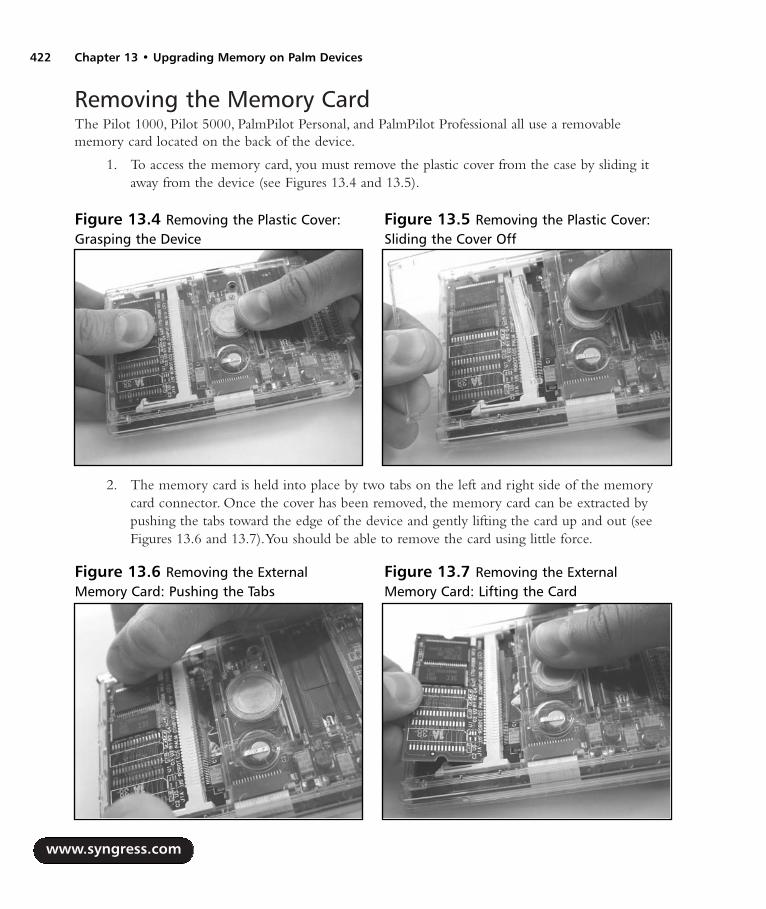
Removing the Memory CardThe Pilot 1000, Pilot 5000, PalmPilot Personal, and PalmPilot Professional all use a removablememory card located on the back of the device.
1. To access the memory card, you must remove the plastic cover from the case by sliding itaway from the device (see Figures 13.4 and 13.5).
2. The memory card is held into place by two tabs on the left and right side of the memorycard connector. Once the cover has been removed, the memory card can be extracted bypushing the tabs toward the edge of the device and gently lifting the card up and out (seeFigures 13.6 and 13.7).You should be able to remove the card using little force.
www.syngress.com
422 Chapter 13 • Upgrading Memory on Palm Devices
Figure 13.4 Removing the Plastic Cover:Grasping the Device
Figure 13.5 Removing the Plastic Cover:Sliding the Cover Off
Figure 13.6 Removing the ExternalMemory Card: Pushing the Tabs
Figure 13.7 Removing the ExternalMemory Card: Lifting the Card
287_HRD_HACK_13.qxd 1/13/04 7:54 PM Page 422

The removed memory card should resemble the images shown in Figures 13.8 and 13.9.
NOTE
Two versions of the Pilot 1000/5000 PCB layout exist. The part number and revision can befound printed on the back of the PCB. The version used in this chapter is 160-0086 REV B.An earlier version, 160-0086 REV P1, requires an additional cut and jumper to complete thehack, as discussed later in the chapter. Both memory cards have “170-0086” silk-screened onthe front.
Adding New Memory1. Before adding new memory to the card, we need to first remove U3, which is the Samsung
KM68V1000BLT-7L 128kB Static RAM component. We won’t need this part anymore.
WARNING: HARDWARE HARM
Be careful when removing the part not to scratch or damage any of the surrounding compo-nents or pull up any PCB traces. The easiest ways to remove a surface-mount part are withan SMD rework station, a flat-blade solder tip (as shown in Figure 13.10), or the ChipQuikSMD Removal Kit (www.chipquik.com), which reduces the overall melting temperature of thesolder on the SMD pads and enables you to lift the part right off the board. (See Chapter 2,“Electrical Engineering Basics,” for a step-by-step example.)
www.syngress.com
Upgrading Memory on Palm Devices • Chapter 13 423
Figure 13.8 Pilot 1000 128kB MemoryCard Front (160-0086 REV B)
Figure 13.9 Pilot 1000 128kB MemoryCard Back (160-0086 REV B)
287_HRD_HACK_13.qxd 1/13/04 7:54 PM Page 423
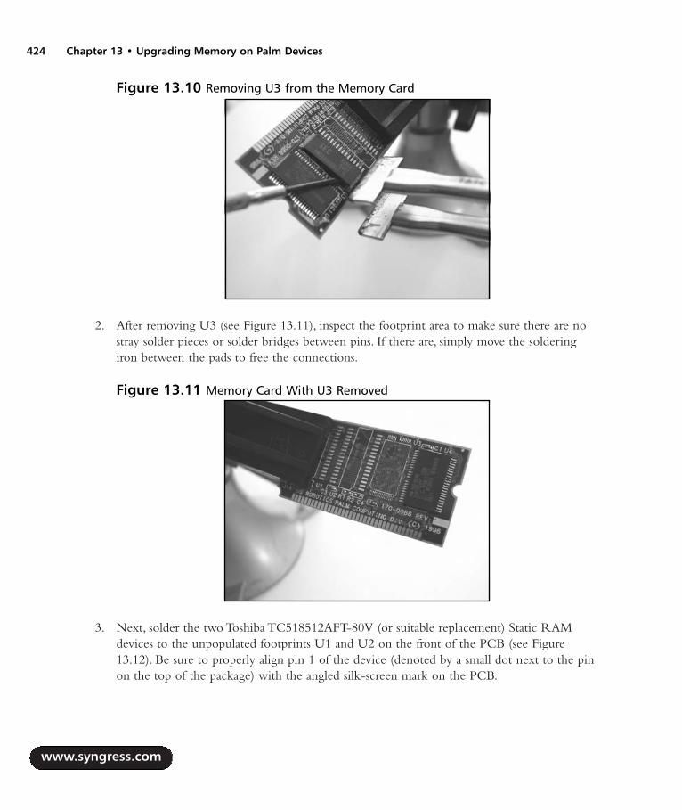
2. After removing U3 (see Figure 13.11), inspect the footprint area to make sure there are nostray solder pieces or solder bridges between pins. If there are, simply move the solderingiron between the pads to free the connections.
3. Next, solder the two Toshiba TC518512AFT-80V (or suitable replacement) Static RAMdevices to the unpopulated footprints U1 and U2 on the front of the PCB (see Figure13.12). Be sure to properly align pin 1 of the device (denoted by a small dot next to the pinon the top of the package) with the angled silk-screen mark on the PCB.
www.syngress.com
424 Chapter 13 • Upgrading Memory on Palm Devices
Figure 13.10 Removing U3 from the Memory Card
Figure 13.11 Memory Card With U3 Removed
287_HRD_HACK_13.qxd 1/13/04 7:54 PM Page 424

4. Next, solder the Toshiba TC7S08FTE85L AND gate to the unpopulated footprint U5 onthe front of the PCB.This device can fit properly on the pads in only one orientation.
5. Add a jumper wire to the R1 location on the front of the PCB (the two pads are above andbetween the “R1” and “R2” silkscreen markings).
If you have the 160-0086 REV B memory card, the modification is complete.Your newly hackedboard should resemble Figure 13.13.
To restore your data previously stored in RAM, simply HotSync the device to your computer.
www.syngress.com
Upgrading Memory on Palm Devices • Chapter 13 425
Figure 13.12 Memory Card With New SRAM Devices Soldered into Place
Figure 13.13 Hacked Pilot 1000 Memory Card With 1MB RAM
287_HRD_HACK_13.qxd 1/13/04 7:54 PM Page 425

If you have a 160-0086 REV P1 memory card, two additional steps are necessary:
1. First, you need to cut the thick trace between U5 pin 1 and the via (the hole immediatelyto the left of U5).
2. Next, solder a jumper wire from U5 pin 1 to U2 pin 22. Both steps are denoted in Figure 13.14.
The Pilot 5000 512kB memory card uses the same PCB and a similar parts placement as the Pilot1000 128kB card shown in this chapter. It will also be denoted with either “160-0086 REV B” or“160-0086 REV P1” on the back and “170-0086” silk-screened on the front. If you have a Pilot 5000512kB memory card that you want to upgrade to 1MB, only two additional steps are required:
1. Solder the Toshiba TC518512AFT-80V (or suitable replacement) Static RAM device to theunpopulated footprint U1.
2. Move the resistor from R2 to R1 (the set of two pads directly to the left).
www.syngress.com
426 Chapter 13 • Upgrading Memory on Palm Devices
Figure 13.14 Modifying the 160-0086 REV P1 Memory Card: Two Additional Steps
287_HRD_HACK_13.qxd 1/13/04 7:54 PM Page 426

Under the Hood: How the Hack WorksFigure 13.15 shows the original Pilot 1000 with 128kB RAM before the hack. Figure 13.16 showsthe after-hack Pilot 1000 with 1MB RAM.
The support for additional memory already exists on the removable memory card, as shown bythe unpopulated footprints on the PCB. Figure 13.17 shows a schematic of the Pilot 1000/5000memory card.
NOTE
Unused connections from the Pilot are not shown.
www.syngress.com
Upgrading Memory on Palm Devices • Chapter 13 427
Figure 13.15 Before Hack: Pilot 1000 With128kB RAM
Figure 13.16 After Hack: Pilot 1000 With1MB RAM
287_HRD_HACK_13.qxd 1/13/04 7:54 PM Page 427

428 Chapter 13 • Upgrading Memory on Palm Devices
Fig
ure
13.
17 S
chem
atic
of
Pilo
t 10
00/5
000
Mem
ory
Car
d (1
60-0
086
REV
B)
VCC
VCC
VCC
VCC
VCC
VCC
A0 A2 A7 A8 A11
A13
A14
A15
A1 A3 A4 A5 A6 A9 A10
A12
A16
A17
A18
A2 A7 A8 A11
A13
A14
A15
A1 A3 A4 A5 A6 A9 A10
A12
A16
A17
A18
A2 A7 A8 A11
A13
A14
A15
A1 A3 A4 A5 A6 A9 A10
A12
A16
A17
A18
A19
A0
A8 A10
A14
A3 A16
A7A1 A6 A15
A5 A9A4 A11
A12
A13
A2A0
D6D1
4D5
D14
D8 D10
D9D7 D14
D0
D2D1 D4
D7
D3D1
0D9
D11
D15
D13
D11
D10
D13
D12
D15
D3D1
D11
D8 D12
D12
D0D9
D2 D4
D8
D5
D15
D13
D6
R21
2
R11
2
U3 KM68
V100
0BLT
-7L
30
245
32
29 28 27 26 25 23 22 21
20 19 18 17 16 15 14 133 2
311
124
117
10
86
9
CS1
GND
WE
OE
D0 D1 D2 D3 D4 D5 D6 D7
A0 A1 A2 A3 A4 A5 A6 A7 A8 A9 A10
A11
A12
A13
A14
A15
A16
VCC
CS2
NC
U1 TC51
8512
AFT-8
0V
22
162924
21 20 19 18 17 15 14 13
112 11 10
9 8 7 6 527 26 23 25
428
331
32
230
CS
GND
WE
OE
D0 D1 D2 D3 D4 D5 D6 D7
A0 A1 A2 A3 A4 A5 A6 A7 A8 A9 A10
A11
A12
A13
A14
A15
A16
VCC
A17
A18
C4 CAP
C2 CAP
U2 TC51
8512
AFT-8
0V
22
162924
21 20 19 18 17 15 14 13
112 11 10
9 8 7 6 527 26 23 25
428
331
32
230
CS
GND
WE
OE
D0 D1 D2 D3 D4 D5 D6 D7
A0 A1 A2 A3 A4 A5 A6 A7 A8 A9 A10
A11
A12
A13
A14
A15
A16
VCC
A17
A18
C3 CAP
U5 TC7S
08FT
E85L
1 24
5 3
U4 PM-1
60-0
090
12
13
14
15 17 19 21 24 26 28 30
1
11 109 8 7 6 5 4
42 41 40 39 38 37 36 35
32
343
3323
24344
16 18 20 22 25 27 29 31
CS0
GND
CS1
D0 D1 D2 D3 D4 D5 D6 D7
NCA1 A2 A3 A4 A5 A6 A7 A8 A9 A10
A11
A12
A13
A14
A15
A16
GND
A17
A18
VCC
VCC
NCNCNC
D8 D9D1
0D1
1D1
2D1
3D1
4D1
5
C1 CAP
A[0:
19]
D[0:
15]
/CSA
0/C
SA1
/RFS
H/U
WE
/LW
E
/OE
RAM Low
RAM High
ROM Palm OS 1.0
287_HRD_HACK_13.qxd 1/13/04 7:54 PM Page 428

Both Toshiba TC518512AFT-80V 512kB SRAM devices (U1 and U2) are selected with the chipselect A1 (/CSA1) line from the Pilot.The lower write enable (/LWE) and upper write enable(/UWE) lines are used to select which 512kB SRAM will be written to at that point in time, eitherthe low segment (U1) or the high segment (U2), respectively.
The Toshiba TC7S08FTE85L AND gate (U5) is used to combine the refresh (/RFSH) and /CSA1lines from the Pilot into a single output enable (/OE) line for the SRAM.The /OE line, which is activelow, is pulled low by the DragonBall processor when it wants to read data from the SRAM.
The /RFSH line is a holdover from the Dynamic RAM (DRAM) support by the DragonBallprocessor.All the required DRAM lines are brought out to the external memory card of the earlyPalm devices. DRAM requires a refresh to ensure that the contents stored in memory remain valid.On each refresh, which happens hundreds of times a second (dependent on the specifications of theDRAM), the contents of each memory cell are read. Due to the way in which the memory cells areconstructed within the DRAM, the reading action “refreshes” the contents of memory. We have notencountered any Palm memory card that uses DRAM, though the support is there.
The two 0 ohm resistor pads, R1 and R2, are used to select the high or low address bit for the512kB SRAM (U2).The other 512kB SRAM (U1), which is installed only in the 1MB configura-tion, is the low segment, and address line A0 is always connected. For example, if only U2 were inplace (the original card, for a total of 512kB), the R2 pads would be shorted, which would connectA0 from the Pilot to A0 of the RAM. When both 512kB RAMs are installed on the card (the hackedcard, for a total of 1MB), the R1 pads would be shorted instead, which would connect A19 from thePilot to A0 of the RAM.This makes U2 the high segment of RAM while U1 remains the low seg-ment. R1 and R2 should never be shorted at the same time.
The common components on all memory cards are the 512kB ROM (marked PM-160-0090 forOS 1.0) containing the Palm operating system and the bypass/decoupling capacitors (denoted as C1-C4), which help reduce electrical noise on the power supply line.
Hacking the PalmPilot Professional and PalmPilot PersonalThe goal of this hack is to upgrade the available RAM of the PalmPilot Professional from 1MB to2MB. With a few additional steps, the PalmPilot Personal can be upgraded from 512kB to 2MB.
Preparing for the HackThe preparation and required parts for this hack are the same as for the previous Pilot 1000/5000memory upgrade hack.
Removing the Memory CardThe Pilot 1000, Pilot 5000, PalmPilot Personal, and PalmPilot Professional all use a removablememory card located on the back of the device.The first step of this hack is described in detail in the“Removing the Memory Card” section of the Pilot 1000/5000 hack.
www.syngress.com
Upgrading Memory on Palm Devices • Chapter 13 429
287_HRD_HACK_13.qxd 1/13/04 7:54 PM Page 429

Once the memory card is removed, it should resemble the images shown in Figures 13.18 and 13.19.
NEED TO KNOW…Two versions of the PalmPilot Personal/Professional PCB layout exist. The part number andrevision can be found printed on the back of the PCB. The version used in this chapter is160-0222 REV A. An earlier version, 160-0184 REV B, requires an additional cut to completethe hack, as discussed later in the chapter. The REV A board has “170-0087” silk-screened onthe front, while the REV B board has “170-00.”
Adding New MemoryFor this hack, you need to solder components to the three unpopulated footprints on the back of thememory card.
1. First, solder the two Toshiba TC518512AFT-80V (or suitable replacement) Static RAMdevices to the unpopulated footprints U3 and U4 on the back of the PCB (denoted byU502 and U504 for the 160-0184 REV B memory card), as shown in Figure 13.20. Be sureto properly align pin 1 of the device (denoted by a small dot next to the pin on the top ofthe package) with the angled silk-screen mark on the PCB.
www.syngress.com
430 Chapter 13 • Upgrading Memory on Palm Devices
Figure 13.18 PalmPilot Professional 1MBMemory Card Front (160-0222 REV A)
Figure 13.19 PalmPilot Professional 1MBMemory Card Back (160-0222 REV A)
287_HRD_HACK_13.qxd 1/13/04 7:54 PM Page 430

2. Next, solder the Toshiba TC7S08FTE85L AND gate to the unpopulated footprint U6 onthe back of the PCB (denoted by U3 for the 160-0184 REV B memory card).This devicecan fit properly on the pads in only one orientation.
If you have the 160-0086 REV B memory card, the modification is complete.Your newly hackedboard should resemble Figure 13.21.
If you have a 160-0184 REV B memory card, add a wire jumper to the R4 location on the frontof the PCB.The pads of R1, R2, R3, and R4 are located in a block on the upper-right corner of theboard.The pads for R4 are the two lower-right pads of the block.
To restore your data previously stored in RAM, simply HotSync the device to your computer.
www.syngress.com
Upgrading Memory on Palm Devices • Chapter 13 431
Figure 13.20 Memory Card With New SRAM Devices Soldered into Place, Back
Figure 13.21 Hacked PalmPilot Professional Memory Card With 2MB RAM, Back
287_HRD_HACK_13.qxd 1/13/04 7:54 PM Page 431

The PalmPilot Personal 512kB memory card uses the same PCB and a similar parts placement asthe PalmPilot Professional 1MB card shown in this chapter. It is also denoted with “160-0222 REVA” on the back and “170-0087” silk-screened on the front. If you have a PalmPilot Personal 512kBmemory card that you want to upgrade to a PalmPilot Professional 1MB card, only three additionalsteps are required (denoted in Figure 13.22):
1. Solder the Toshiba TC518512AFT-80V (or suitable replacement) Static RAM device to theunpopulated footprint U1.
2. Move the resistor from R2 to R1 (the two pads directly above).
3. To expand the 1MB board to 2MB, follow the upgrade details in this chapter.
www.syngress.com
432 Chapter 13 • Upgrading Memory on Palm Devices
Figure 13.22 Modifying the PalmPilot Personal 512kB to a PalmPilot Professional 1MB: TwoAdditional Steps
287_HRD_HACK_13.qxd 1/13/04 7:55 PM Page 432
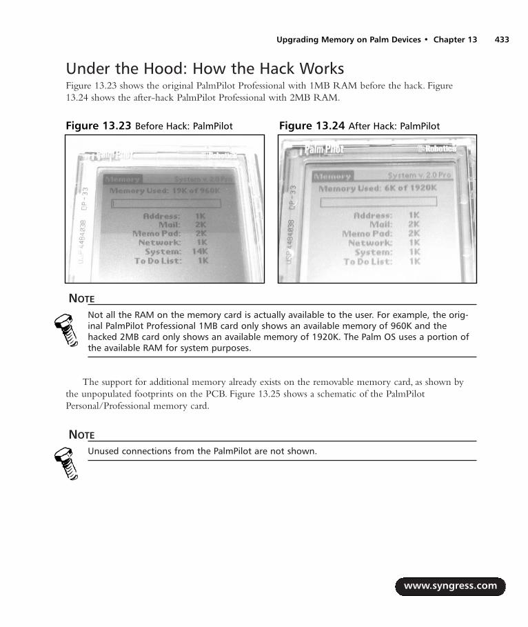
Under the Hood: How the Hack WorksFigure 13.23 shows the original PalmPilot Professional with 1MB RAM before the hack. Figure13.24 shows the after-hack PalmPilot Professional with 2MB RAM.
NOTE
Not all the RAM on the memory card is actually available to the user. For example, the orig-inal PalmPilot Professional 1MB card only shows an available memory of 960K and thehacked 2MB card only shows an available memory of 1920K. The Palm OS uses a portion ofthe available RAM for system purposes.
The support for additional memory already exists on the removable memory card, as shown bythe unpopulated footprints on the PCB. Figure 13.25 shows a schematic of the PalmPilotPersonal/Professional memory card.
NOTE
Unused connections from the PalmPilot are not shown.
www.syngress.com
Upgrading Memory on Palm Devices • Chapter 13 433
Figure 13.23 Before Hack: PalmPilot Figure 13.24 After Hack: PalmPilot
287_HRD_HACK_13.qxd 1/13/04 7:55 PM Page 433

434 Chapter 13 • Upgrading Memory on Palm Devices
Fig
ure
13.
25 S
chem
atic
of
Palm
Pilo
t Pe
rson
al/P
rofe
ssio
nal M
emor
y C
ard
160-
0222
REV
A
VCC
VCC
VCC
VCC
VCC
VCC
VCC
A0 A2 A7 A8 A11
A13
A14
A15
A1 A3 A4 A5 A6 A9 A10
A12
A16
A17
A18
A2 A7 A8 A11
A13
A14
A15
A1 A3 A4 A5 A6 A9 A10
A12
A16
A17
A18
A2 A7 A8 A11
A13
A14
A15
A1 A3 A4 A5 A6 A9 A10
A12
A16
A17
A18
A19
A0
D4D1
1D1
0
D14
D9
D1
D5D1
2
D13
D2
D13
D9
D3
D10
D4
D2
D7 D8
D6
D3 D6D5
D8D0
D15
D0
D12
D15
D11
D1 D14
D7
A0 A2 A7 A8 A11
A13
A14
A15
A1 A3 A4 A5 A6 A9 A10
A12
A16
A17
A18
A2 A7 A8 A11
A13
A14
A15
A1 A3 A4 A5 A6 A9 A10
A12
A16
A17
A18
D4D1
1D1
0
D14
D1
D12
D13
D9
D3D2 D6D5
D8 D15
D0 D7
A19
R11
2
R21
2
U1 TC51
8512
AFT-8
0V
22
162924
21 20 19 18 17 15 14 13
112 11 10
9 8 7 6 527 26 23 25
428
331
32
230
CS
GND
WE
OE
D0 D1 D2 D3 D4 D5 D6 D7
A0 A1 A2 A3 A4 A5 A6 A7 A8 A9 A10
A11
A12
A13
A14
A15
A16
VCC
A17
A18
C2 CAP
C3 CAP
U2 TC51
8512
AFT-8
0V
22
162924
21 20 19 18 17 15 14 13
112 11 10
9 8 7 6 527 26 23 25
428
331
32
230
CS
GND
WE
OE
D0 D1 D2 D3 D4 D5 D6 D7
A0 A1 A2 A3 A4 A5 A6 A7 A8 A9 A10
A11
A12
A13
A14
A15
A16
VCC
A17
A18
U7 160-
0223
-06
12
13
14
15 17 19 21 24 26 28 30
1
11 109 8 7 6 5 4
42 41 40 39 38 37 36 35
32
343
3323
24344
16 18 20 22 25 27 29 31
CS0
GND
CS1
D0 D1 D2 D3 D4 D5 D6 D7
NCA1 A2 A3 A4 A5 A6 A7 A8 A9 A10
A11
A12
A13
A14
A15
A16
GND
A17
A18
VCC
VCC
NCNCNC
D8 D9D1
0D1
1D1
2D1
3D1
4D1
5
C4 CAP
U5 TC7S
08FT
E85L
1 24
5 3
C5CA
P
U4 TC51
8512
AFT-8
0V
22
162924
21 20 19 18 17 15 14 13
112 11 10
9 8 7 6 527 26 23 25
428
331
32
230
CS
GND
WE
OE
D0 D1 D2 D3 D4 D5 D6 D7
A0 A1 A2 A3 A4 A5 A6 A7 A8 A9 A10
A11
A12
A13
A14
A15
A16
VCC
A17
A18
C6 CAP
U3 TC51
8512
AFT-8
0V
22
162924
21 20 19 18 17 15 14 13
112 11 10
9 8 7 6 527 26 23 25
428
331
32
230
CS
GND
WE
OE
D0 D1 D2 D3 D4 D5 D6 D7
A0 A1 A2 A3 A4 A5 A6 A7 A8 A9 A10
A11
A12
A13
A14
A15
A16
VCC
A17
A18
U6 TC7S
08FT
E85L
1 24
5 3
A[0:
19]
D[0:
15]
/CSA
0/C
SA1
/RFS
H/U
WE
/LW
E
/UW
E/L
WE
/CSA
3
/RFS
H
RAM Low
Segment 1
RAM High
Segment 2
ROM Palm OS 2.0
RAM Low
Segment 3
RAM High
Segment 4
287_HRD_HACK_13.qxd 1/13/04 7:55 PM Page 434

After the hack is completed, there will be four Toshiba TC518512AFT-80V 512kB SRAMdevices on board, comprising a total of 2MB.The total available RAM is separated into two 1MBsegments, each containing two 512kB devices.The first 1MB segment, containing the two originalSRAM parts U1 and U2, is selected with the /CSA1 chip select from the PalmPilot.The lower writeenable (/LWE) and upper write enable (/UWE) lines are used to select which 512kB SRAM devicewill be written to at that point in time, either the low segment (U1) or the high segment (U2),respectively.
The second 1MB segment, containing the newly added SRAM parts U3 and U4, is selected withthe /CSA3 chip select from the PalmPilot.The lower write enable (/LWE) and upper write enable(/UWE) lines are used to select which 512kB SRAM device will be written to at that point in time,either the low segment (U3) or the high segment (U4), respectively.
The two Toshiba TC7S08FTE85L AND gates (the original U5 and the added U6) are used tocombine the refresh (/RFSH) and chip select lines (/CSA1 for the first 1MB segment, and /CSA3for the second 1MB segment) from the PalmPilot into output enable (/OE) lines for the SRAMdevices.The /OE line, which is active low, is pulled low by the DragonBall processor when it wantsto read data from the SRAM.
The /RFSH line is a holdover from the DRAM support by the DragonBall processor.All therequired DRAM lines are brought out to the external memory card of the early Palm devices.DRAM requires a refresh to ensure that the contents stored in memory remain valid. On eachrefresh, which happens hundreds of times a second (dependent on the specifications of the DRAM),the contents of each memory cell are read. Due to the way in which the memory cells are con-structed within the DRAM, the reading action “refreshes” the contents of memory. We have notencountered any Palm memory card that actually uses DRAM, even though the support is there.
After adding three more components to the back of the memory card, the extra 1MB RAM seg-ment is automatically handled by the Palm operating system.
The common components on all memory cards are the 512kB ROM (marked “160-0223-06” forOS 2.0) containing the Palm operating system and the bypass/decoupling capacitors (denoted asC2–C6), which help reduce electrical noise on the power supply line.
www.syngress.com
Upgrading Memory on Palm Devices • Chapter 13 435
287_HRD_HACK_13.qxd 1/13/04 7:55 PM Page 435

Hacking the Palm m505 The goal of this hack is to upgrade the available RAM of the Palm m505 from 8MB to 16MB.Figures 13.26 and 13.27 show product shots of the Palm m505 hardware.
Preparing for the HackTo prepare for hacking your Palm m505, be sure to:
1. HotSync the device to your desktop to back up all data. When you open up the device anddisconnect the system power, all applications and data stored in RAM will be erased. Oncethe power is replaced at the end of the hack, the system will be completely reinitialized(with the exception of data stored in Flash ROM).
2. If your device has a screen protector flap, remove it by simply sliding it out of its holder.This will make it easier to remove the back cover of the Palm while it is lying on its face.
3. Remove any external SecureDigital memory cards.
The only component needed for this hack is the following:
1 Samsung KM416S8030BT-GL (or -FL, -F8, -G8) 16MB Low-Voltage SynchronousDynamic RAM (54-pin TSOP II package)
A Torx driver (size T5 or T6) is required to remove the screws from the back of the device, and asoldering iron is needed to remove the old memory component and add the new one. Figure 13.28shows a picture of those components.
www.syngress.com
436 Chapter 13 • Upgrading Memory on Palm Devices
Figure 13.26 The Palm m505, Front Figure 13.27 The Palm m505, Back
287_HRD_HACK_13.qxd 1/13/04 7:55 PM Page 436

NOTE
Samsung has discontinued the KM416S8030 part number scheme. If you cannot obtain thisexact component, any Toshiba TC59SM716AFT, Hynix Semiconductor HY57V281620, orVanguard International VG36128161BT family (low-power versions only) can be used as drop-in replacements. Other second-source parts could also be used. The 8Mbit x 16 SDRAM config-uration that is needed is common on many PC100 DIMM memory cards used in laptops. A128MB card containing eight 16MB chips would be ideal for this hack, leaving you with a fewextra pieces in case of a mistake. You could purchase a pre-owned board (on eBay or from acomputer parts store, for example) for $10 to $25 specifically to use the components on it.
Opening the PalmThe Palm m505 casing is held together by four Torx screws. Usually, size T6 is used if the device wasmanufactured in the United States, and size T5 is used if the device was manufactured in Hungary.However, this does not always hold true; the model used in this chapter was manufactured in theUnited States and is held together with a T5 size.
www.syngress.com
Upgrading Memory on Palm Devices • Chapter 13 437
Figure 13.28 Required Components for the Palm m505 Hack
287_HRD_HACK_13.qxd 1/13/04 7:55 PM Page 437
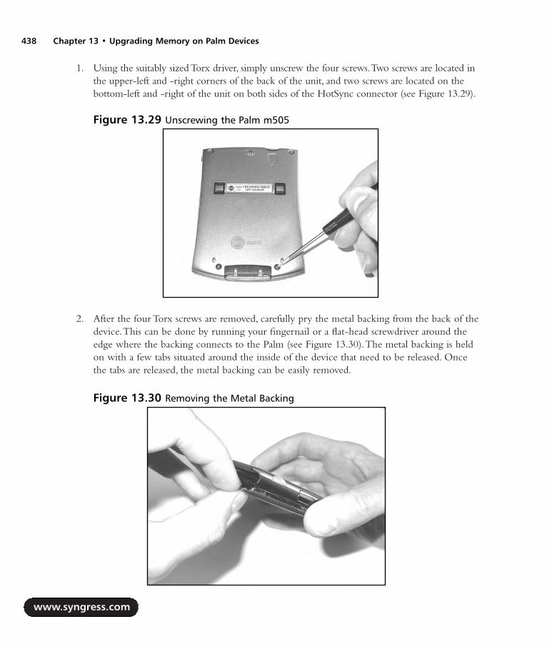
1. Using the suitably sized Torx driver, simply unscrew the four screws.Two screws are located inthe upper-left and -right corners of the back of the unit, and two screws are located on thebottom-left and -right of the unit on both sides of the HotSync connector (see Figure 13.29).
2. After the four Torx screws are removed, carefully pry the metal backing from the back of thedevice.This can be done by running your fingernail or a flat-head screwdriver around theedge where the backing connects to the Palm (see Figure 13.30).The metal backing is heldon with a few tabs situated around the inside of the device that need to be released. Oncethe tabs are released, the metal backing can be easily removed.
www.syngress.com
438 Chapter 13 • Upgrading Memory on Palm Devices
Figure 13.29 Unscrewing the Palm m505
Figure 13.30 Removing the Metal Backing
287_HRD_HACK_13.qxd 1/13/04 7:55 PM Page 438

With the metal backing removed from the Palm m505, we now have complete access to theinternal circuitry.Your unit should resemble the image in Figure 13.31.
Removing the Main Circuit Board1. We now need to gain access to the main circuit board so we can remove the old RAM
device and solder on the new one. First, take away both sides of the Palm housing from thecircuitry.The circuit board is simply press-fit into the case, so it should come out fairly easilyif you turn the entire unit upside down. If that doesn’t work, lightly press on the LCD dis-play on the front of the Palm.The circuitry should just pop out the other side.
WARNING: HARDWARE HARM
Be sure to take extreme care when handling the exposed Palm circuit board. Take properantistatic precautions, and be gentle with all connectors.
www.syngress.com
Upgrading Memory on Palm Devices • Chapter 13 439
Figure 13.31 Opened Palm m505 Showing Back Side of Circuitry
287_HRD_HACK_13.qxd 1/13/04 7:55 PM Page 439

2. With the circuit board removed from the housing, first disconnect the internal rechargeablebattery by disconnecting the small two-conductor plug (see Figure 13.32).
3. Next, the LCD panel needs to be removed in order to give us unobstructed access to thePalm circuit board. Removing the display is a two-step process, as shown in Figures 13.33and 13.34. First, with the back of the device facing you, use your right hand to reach under-neath the circuitry and flip the LCD panel up and to the right.Your unit should resemblethe image in Figure 13.33.
www.syngress.com
440 Chapter 13 • Upgrading Memory on Palm Devices
Figure 13.32 Disconnecting the Internal Battery
Figure 13.33 Removing the Display: The LCD Panel Flipped Up and Right
287_HRD_HACK_13.qxd 1/13/04 7:55 PM Page 440

4. Next, remove the flex connector that connects the display to the rest of the Palm circuitry(see Figure 13.34). Be very careful to not bend or tear the flex cable and connector, becausethe assembly is very fragile.
Removing the MemoryNow that we have unobstructed access to the Palm circuit board, we can remove the originalSamsung K4S641632D Synchronous DRAM memory device from the Palm circuit board (denotedwith an arrow in Figure 13.35).This component provides 8MB of RAM in a 4-bank × 1MB × 16-bitconfiguration. We will be replacing this chip with the Samsung KM416S8030BT-GL device, whichprovides 16MB of RAM in a 4-bank × 2MB × 16-bit configuration.
www.syngress.com
Upgrading Memory on Palm Devices • Chapter 13 441
Figure 13.34 Removing the Display: Remove the Flex Connector
Figure 13.35 Palm m505 Circuit Board Showing 8MB RAM Device to Remove
287_HRD_HACK_13.qxd 1/13/04 7:55 PM Page 441

WARNING: HARDWARE HARM
When removing the RAM device, be careful to not scratch or damage any of the surroundingcomponents or pull up any PCB traces. Using the ChipQuik SMD rework kit makes it easy toremove the fine-pitch memory device.
After following the instructions on the package (which consist of simply applying a standard no-clean flux to the SMD pins and then applying a low-melting-point solder), you can easily remove thesurface-mount part from the board. Use rubbing alcohol to remove any residue from the solder pads.Verify that the solder pads are clean and free from cuts or solder jumps before proceeding to the nextstep.Your circuit board should resemble the image in Figure 13.36.
Adding New MemoryWith the old 8MB RAM device removed, it is time to add the new 16MB RAM in its place. Simplysolder the Samsung KM416S8030BT-GL (or suitable replacement) SDRAM to the now empty foot-print. Be sure to properly align pin 1 of the device (denoted by a small dot next to the pin on the topof the package) with the black triangle mark on the PCB. When the new memory is successfully sol-dered into place, your circuit board should resemble the image in Figure 13.37.
www.syngress.com
442 Chapter 13 • Upgrading Memory on Palm Devices
Figure 13.36 Palm m505 Circuit Board with Old RAM Removed
287_HRD_HACK_13.qxd 1/13/04 7:55 PM Page 442

To complete the hack, a final step is required.A 0-ohm, four-resistor array (also called a jumper orresistor network) located on the front of the circuit board needs to be moved. Moving the jumper willredirect the high-order address and bank-switch lines going to the SDRAM device from theDragonBall microprocessor.This configures the Palm m505 to use 16MB of RAM instead of the fac-tory-default 8MB. Figure 13.38 shows the resistor network (denoted with an arrow) that needs to bedesoldered and moved to its new location.
This step is extremely tricky because the jumper is very small and you need to have a steady handto unsolder it from the original location and resolder it to the new location (the set of pads to the
www.syngress.com
Upgrading Memory on Palm Devices • Chapter 13 443
Figure 13.37 Palm m505 Circuit Board with New 16MB Device Soldered into Place
Figure 13.38 Palm m505 Circuit Board Showing Jumper to Move
287_HRD_HACK_13.qxd 1/13/04 7:55 PM Page 443

immediate left of the original). Figure 13.39 shows the original location of the memory configurationjumper. Figure 13.40 shows the jumper moved into its new location. If you lose or damage the orig-inal resistor array, a replacement part can be installed in its place (Panasonic EXB-38VR000V, Digi-Key Part #Y9000CT-ND).
On the new footprint, the rightmost pad is unused and unconnected, so if you accidentally createa solder bridge on the right side of the device (which is easy to do, as you can see in Figure 13.40),the memory hack will still function as intended.
When you are changing the location of the jumper, it may help to peel back a bit of the whiteprotective sticker on the circuit board to give you more room to maneuver the soldering iron.Thisprotective sticker exists to prevent the traces from the main circuit board from coming into contact
www.syngress.com
444 Chapter 13 • Upgrading Memory on Palm Devices
Figure 13.39 Memory Configuration Jumper, Original Location for 8MB
Figure 13.40 Memory Configuration Jumper, New Location for 16MB
287_HRD_HACK_13.qxd 1/13/04 7:55 PM Page 444

with the metal backing of the LCD module. If you peel the sticker back, be sure to replace it whenyou are done with the relocation process.
Now that the jumper has been moved, the memory upgrade modification is complete.Afterreplacing the circuit board into the Palm housing, reconnect the LCD and battery and reassemble thecase.The device should simply power up in its factory reset condition and show 16MB of availableRAM. If the unit does not immediately power up, press a paper clip into the small Reset hole on theback of the device to reset the Palm.
To restore your data previously stored in RAM, simply HotSync the device to your computer.
Under the Hood: How the Hack WorksFigure 13.41 shows the original Palm m505 with 8MB RAM before the hack. Figure 13.42 showsthe after-hack Palm m505 with 16MB RAM.
The support for additional memory already exists in the Palm m505, as shown by the simplememory replacement and the additional footprint location for the jumper.
The original Samsung K4S641632D Synchronous DRAM memory device installed in the Palmm505 provides 8MB of RAM in a 4-bank × 1MB × 16-bit configuration.The 16MB device,Samsung KM416S8030BT-GL or equivalent, provides 16MB of RAM in a 4-bank × 2MB × 16-bitconfiguration.The pinouts for both devices are exactly the same, and the only difference is the size ofeach of the four banks (which are increased from 1MB to 2MB each). Rumor has it that the devicecould also be upgraded to a 32MB RAM capacity using a 4-bank × 4MB ×16-bit configurationdevice, though the Palm OS will not support the entire memory size without software modificationto the OS.
The critical part of the hack is moving the 0-ohm, four-resistor array. If the jumper was notmoved, the Palm would still only recognize 8MB of RAM, even if the 16MB device was installed.Moving the jumper will redirect the high-order address and bank-switch lines going to the SDRAM
www.syngress.com
Upgrading Memory on Palm Devices • Chapter 13 445
Figure 13.41 Before Hack: Palm m505With 8MB RAM
Figure 13.42 After Hack: Palm m505 With16MB RAM
287_HRD_HACK_13.qxd 1/13/04 7:55 PM Page 445

device from the DragonBall 68VZ328 microprocessor.This configures the Palm m505 to use 16MBof RAM instead of the factory-default 8MB.
There are two groups of eight jumper pads on the Palm M505 circuit board.They are all locatedbetween the cursor keys and the To Do key on the front of the circuit board.The connections to thepads are denoted in Figure 13.43, showing the original 8MB configuration on the right and 16MBconfiguration on the left. Only six of the eight pads are actually used.The remaining pads (the farright pair of each group) are unused and unconnected. With the 0-ohm resistor array in place, thefour sets of top and bottom pads will be connected.
With the resistor array in its original 8MB configuration, the lines between the processor andSDRAM are connected as follows:
Processor address line A12 to SDRAM address line A11
Processor address line A13 to SDRAM bank select line BS0
Processor address line A14 to SDRAM bank select line BS1
www.syngress.com
446 Chapter 13 • Upgrading Memory on Palm Devices
Figure 13.43 Jumper Pad Connections: Right, Original 8MB Configuration; Left, 16MBConfiguration
287_HRD_HACK_13.qxd 1/13/04 7:55 PM Page 446

With the resistor array moved to the 16MB configuration, the lines between the processor andSDRAM are connected as follows:
Processor address line A12 to SDRAM bank select line BS1
Processor address line A13 to SDRAM address line A11
Processor address line A15 to SDRAM bank select line BS0
By rearranging the lines between the SDRAM and the processor, the additional address line A15is used as a high-order bank-select switch. Since the size of each bank in the SDRAM is now 2MBinstead of 1MB,A14 is not used for memory configuration purposes.
Technical InformationThis portion of the chapter discusses some additional technical details of the Palm OS and Palm PDAhardware.
HardwareHardware devices running the Palm OS currently use either the Motorola DragonBall MC68328microprocessor family (based on the Motorola MC68EC000 core) or the Texas Instruments OMAPprocessor family (based on the ARM core).The original DragonBall processor, released in 1995, hasbeen joined by two subsequent updates, the DragonBall EZ and the DragonBall VZ. Each release hasbecome more streamlined for use in PDAs and other portable devices.Table 13.2 shows a selection ofPalm OS devices and their core processors.
Table 13.2 A Selection of Palm OS Devices and Their Core Processors
Device Processor Type
U.S. Robotics PalmPilot Personal/Professional DragonBall (16MHz)3Com Palm III DragonBall EZ (16MHz)IBM WorkPad c3 (Palm V) DragonBall EZ (16MHz)Kyocera QCP 6035 smartphone DragonBall EZ (16MHz)Palm Computing m105 DragonBall EZ (16MHz)Palm Computing m500/m505 DragonBall VZ (33MHz)Handspring Treo 300 DragonBall VZ (33MHz)Palm Zire 71 OMAP310 (144MHz)Palm Tungsten T2 OMAP1510 (144MHz)
Early and low-end Palm devices are powered by two standard alkaline AAA batteries, which areremovable and replaceable. High-end and newer models contain a nonremovable, internal lithium-ion(Li-Ion) battery (rechargeable through the HotSync cradle or external charging device).Alkaline bat-teries typically last longer than their rechargeable counterparts and add a level of convenience in
www.syngress.com
Upgrading Memory on Palm Devices • Chapter 13 447
287_HRD_HACK_13.qxd 1/13/04 7:55 PM Page 447

emergency situations, since they are available in almost any retail store.The disadvantage to using non-rechargeable batteries is that they must be properly discarded after use.
Palm devices use battery-backed RAM to store application and user data.The operating systemand other nontransient components are often stored in Flash-based ROM devices.The memory foreach Palm OS device resides on a module known as a card. Each card is a logical definition and doesnot necessarily correspond to a physical card (although it does on the original Pilot and PalmPilothardware).The Palm OS is designed to be modular in that multiple cards (each containing RAM,ROM, or both) can be functional in a given device.This allows for future expansion in which a Palmdevice might contain an internal card (e.g., RAM and ROM for the operating system) and anexternal card (e.g., user application and data storage). For example, many Palm devices contain anexpansion slot for SecureDigital/MultiMediaCard (SD/MMC) memory cards.The Sony CLIÉ familyof Palm devices supports the Sony Memory Stick.
File SystemMemory requirements are typically less for the Palm OS than for other embedded operating systemssuch as Windows CE/Pocket PC.The RAM in a Palm device is used for volatile storage and is logi-cally divided into dynamic memory and storage memory.
Dynamic memory, analogous to RAM installed in a typical desktop system, is used as working spacefor the program stack and short-term data (e.g., pen strokes, key presses, system events, video memory,global variables, and user interface structures).The size of the dynamic memory region depends on theOS version and on the total memory on the Palm device and changes constantly during device use.
The remainder of RAM is used as storage memory, analogous to a disk drive. RAM sizes of currentPalm devices range from 1MB to 32MB.Though the size might seem small, a standard Palm OSapplication ranges in size from 2kB to 100kB.
Memory MapThe base starting addresses for the RAM and ROM areas of Palm devices vary depending on theprocessor type, as does the memory range allocated to each memory card.The DragonBall family ofprocessor supports up to 4GB of address space. Figure 13.44 shows the memory maps and relevantregions for typical Palm OS devices using DragonBall, DragonBall EZ, or DragonBall VZ processors.
www.syngress.com
448 Chapter 13 • Upgrading Memory on Palm Devices
287_HRD_HACK_13.qxd 1/13/04 7:55 PM Page 448

The Palm uses chip select /CSA0 to access the ROM. Early versions of Palm devices had 256kBor 512kB of ROM. Current versions contain up to 8MB of Flash ROM and typically have over 2MBof unused space available for user (non-system) storage.The contents of Flash ROM are nonvolatileand remain intact even with loss of battery power to the device. HandEra’s JackFlash tool (www.han-dera.com/Products/JackFlash.aspx) takes advantage of the unused memory areas of Flash memory toback up user applications and databases.
Chip selects /CSA1 and /CSA3 are used to access the RAM. For earlier Palm devices with 1MBof RAM, only /CSA1 is used. For devices with larger RAM areas, such as the Palm III (which has2MB of RAM), /CSA3 is used to access the second segment of RAM.
Database StructureThe Palm File Format Specification provides a detailed view into the file formats supported by PalmOS. In general, all data conforms to one of the three defined file types:
Palm Database (PDB) Record database used to store application or user data.
Palm Resource (PRC) Resource database (similar structure to a Palm database).Applications running on Palm OS (also referred to as programs, executables, or binaries) aresimply resource databases containing code and user interface resource elements.
Palm Query Application (PQA) Palm database containing Web content for use withPalm OS wireless devices.
Databases are similar to files on a disk drive; the difference is that they are stored in a sequence ofmemory chunks called records or resources instead of in one contiguous area.The database file in devicememory contains header information and a sequential list of pointers to records or resources.Therecords within a database are similarly structured with record header information and record data.
www.syngress.com
Upgrading Memory on Palm Devices • Chapter 13 449
Figure 13.44 Base Addresses of Relevant Memory Regions by Processor Type
0000 0000h
1000 0000 h
10C0 0000 h
2000 0000h
FFFF F 000 h
RAM
ROM
ProcessorRegisters
Card 0 Base
Card 1 Base
3000 0000 h Card 2 Base
10C0 0000 h
2000 0000h
FFFF F000h
ROM
Processor
Card 0 Base
Card 1 Base
4000 0000h Card 2 Base
DragonBall0000 0000 h
RAM1000 0000 h
2000 0000 h
FFFF F000h
ROM
Processor
Card 0 Base
Card 1 Base
4000 0000 h Card 2 Base
0000 0000h
RAM
DragonBall EZ DragonBall VZ
Registers Registers
287_HRD_HACK_13.qxd 1/13/04 7:55 PM Page 449

Palm Links on the WebThe Web has a great number of resources for fans of Palm devices.This section provides just a smallsampling of the hundreds (if not thousands) of Palm-related Web sites to whet your appetite.
Technical InformationIf you are interested in learning more about the intricate details of the Palm OS and its underlyinghardware, the following sites serve as good starting points:
Palm Developer Resources www.palmone.com/us/developers
PalmOS.com Developer Documentation www.palmos.com/dev/support/docs
Motorola MC68328 DragonBall Integrated Processor User’s Manual http://e-www.motorola.com
ARM Processor Documentation www.arm.com/documentation
Palm HacksThis chapter hits only the tip of the iceberg when it comes to hacking your Palm. Hardware hackingand Palm devices go hand in hand, as can be seen by the variety of hacks available for the devices:
Palm de COOL! www.fureai.or.jp/%7Emori-t/e_whatsnew.html Eclectic collec-tion of Japanese Palm hacks, mostly visual effects.
Stephanie’s Handspring Visor Modification Page www.felesmagus.com/visor
Peter Strobel’s Pilot Pages: www.pspilot.de Technical information and do-it-yourselfmodifications.
Pilot Hardware Main Page www.massena.com/darrin/pilot/luiz/hardware.htmTechnical information and do-it-yourself modifications.
More Memory Upgrades Palm III (2MB to 4MB) www.harbaum.org/till/palm/memory/index.html
Palm III (2MB to 8MB) www.interlog.com/~tcharron/Palm8M/III8M.html
Palm IIIe (2MB to 4MB/8MB) www.interlog.com/~tcharron/Palm8M/IIIex.html
Palm IIIx (4MB to 8MB) www.interlog.com/~tcharron/Palm8M/IIIex.html
Palm V (2MB to 8MB) www.interlog.com/~tcharron/Palm8M/V8/V8.html
Palm m100 (2MB to 8MB) www-2.cs.cmu.edu/~tew/m100hack
www.syngress.com
450 Chapter 13 • Upgrading Memory on Palm Devices
287_HRD_HACK_13.qxd 1/13/04 7:55 PM Page 450

Hardware HackingTechnical Reference
Part III
451
287_HRD_HACK_14.qxd 1/14/04 9:05 AM Page 451

287_HRD_HACK_14.qxd 1/14/04 9:05 AM Page 452

Operating Systems Overview
Topics in this Chapter:
OS Basics
Drivers
Linux
VxWorks
Windows CE
Chapter 14
453
287_HRD_HACK_14.qxd 1/14/04 9:05 AM Page 453

IntroductionA computer without any operating software is just an expensive pile of metal, plastic, and silicon.Physically, a computer contains processors, memory, disks, and input/output devices such as keyboards,monitors, and drives.The operating system (OS) is the software that controls all these components.When you are writing a program, you don’t know the physical layout of every computer your pro-gram will be run on. If you did know, you certainly wouldn’t want to waste your time telling yourprogram exactly how to store data on a hard disk.The OS’s job is to take care of that hardware accessinformation for you.The OS’s other job is to monitor resource allocation.Your computer might berunning two programs, such as a Web browser and an e-mail program, at the same time.They can’tboth use the physical network interface simultaneously.The OS assigns physical resources to eachapplication so the application designers don’t have to worry about such things.
NEED TO KNOW…. UNDERSTANDING LAYERING
This description of a computer’s physical versus software layers is a simplification. Most com-puters are likely to have multiple layers of increasing abstraction in order to work:
Physical devices (processor, disks, etc.) Microprogramming interpreter for the machine language Machine language Operating system System programs Application programs
If you do a lot of operating system programming, you’ll want to learn more about howthese layers interact.
OS BasicsIn this section, we introduce you to some of the fundamental concepts of operating systems:
Memory
File systems
Input and output
Processes
System calls
The Shell
www.syngress.com
454 Chapter 14 • Operating Systems Overview
287_HRD_HACK_14.qxd 1/14/04 9:05 AM Page 454

Operating Systems Overview • Chapter 14 455
NEED TO KNOW… MEMORY OR DISK?It’s easy to get confused between the terms memory (or RAM) and disk (or hard disk). We’llget into details in this chapter, but for now, just be aware that memory is temporary storagethat goes away when the computer is turned off, and disk is permanent storage that existseven when the computer has no power.
MemoryMemory, or random access memory (RAM), is a special part of your computer that is designed to holdtemporary information. It’s very fast, but it’s also volatile—it goes away when you turn off the com-puter or when battery power is removed. Whatever a program is doing at any given moment needs tobe tracked in memory. Managing memory is one of the OS’s most important jobs.
Sometimes it seems like we shouldn’t have to worry about memory anymore. I remember howproud I was when I upgraded the first computer I ever personally owned to 640KB of memory, andright now I’m typing on a computer with 512MB of memory.That’s 1,000 times as much memory asmy first computer, but my current computer is certainly not 1,000 times faster or more efficient oruseful than that first one. (Heck, with my constant Internet connection, this computer probably makesme much less efficient.) But the more memory we have accessible to us, the more developers aregoing to write programs that use a lot of memory. No matter how much space you have, your pro-grams may end up using it all. So it’s very important for the operating system to manage memory asquickly and as efficiently as it possibly can.
Physical MemoryPhysical memory is a type of hardware that the computer can retrieve information from very quickly.Information stored at any address on the hardware can be directly accessed with an address that refersto a specific location on the hardware. Because this direct access allows information to be retrievedfrom any random point in memory, this sort of memory is known as random access memory.
As Figure 14.1 illustrates, a program can request the information that is stored in physicalmemory at any location. Here the program requests the data stored in physical memory at the loca-tion addressed 0K.The information in that memory location—in this illustration, the letter A—isreturned to the program.
www.syngress.com
287_HRD_HACK_14.qxd 1/14/04 9:05 AM Page 455
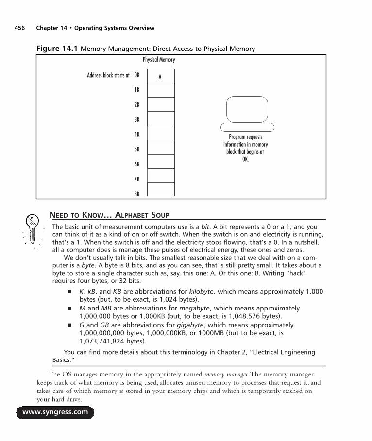
NEED TO KNOW… ALPHABET SOUP
The basic unit of measurement computers use is a bit. A bit represents a 0 or a 1, and youcan think of it as a kind of on or off switch. When the switch is on and electricity is running,that’s a 1. When the switch is off and the electricity stops flowing, that’s a 0. In a nutshell,all a computer does is manage these pulses of electrical energy, these ones and zeros.
We don’t usually talk in bits. The smallest reasonable size that we deal with on a com-puter is a byte. A byte is 8 bits, and as you can see, that is still pretty small. It takes about abyte to store a single character such as, say, this one: A. Or this one: B. Writing “hack”requires four bytes, or 32 bits.
K, kB, and KB are abbreviations for kilobyte, which means approximately 1,000bytes (but, to be exact, is 1,024 bytes).
M and MB are abbreviations for megabyte, which means approximately1,000,000 bytes or 1,000KB (but, to be exact, is 1,048,576 bytes).
G and GB are abbreviations for gigabyte, which means approximately1,000,000,000 bytes, 1,000,000KB, or 1000MB (but to be exact, is1,073,741,824 bytes).
You can find more details about this terminology in Chapter 2, “Electrical EngineeringBasics.”
The OS manages memory in the appropriately named memory manager.The memory managerkeeps track of what memory is being used, allocates unused memory to processes that request it, andtakes care of which memory is stored in your memory chips and which is temporarily stashed onyour hard drive.
www.syngress.com
456 Chapter 14 • Operating Systems Overview
Figure 14.1 Memory Management: Direct Access to Physical Memory
Physical Memory
0K
1K
2K
3K
4K
5K
6K
7K
8K
Address block starts at
Program requestsinformation in memory
block that begins at 0K.
A
287_HRD_HACK_14.qxd 1/14/04 9:05 AM Page 456
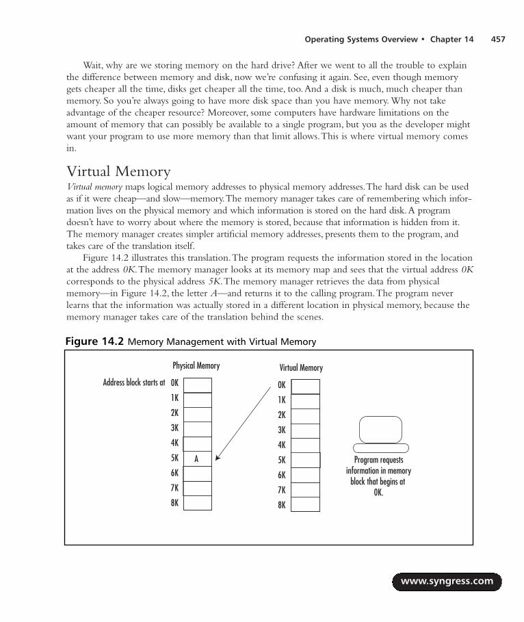
Operating Systems Overview • Chapter 14 457
Wait, why are we storing memory on the hard drive? After we went to all the trouble to explainthe difference between memory and disk, now we’re confusing it again. See, even though memorygets cheaper all the time, disks get cheaper all the time, too.And a disk is much, much cheaper thanmemory. So you’re always going to have more disk space than you have memory. Why not takeadvantage of the cheaper resource? Moreover, some computers have hardware limitations on theamount of memory that can possibly be available to a single program, but you as the developer mightwant your program to use more memory than that limit allows.This is where virtual memory comesin.
Virtual Memory Virtual memory maps logical memory addresses to physical memory addresses.The hard disk can be usedas if it were cheap—and slow—memory.The memory manager takes care of remembering which infor-mation lives on the physical memory and which information is stored on the hard disk.A programdoesn’t have to worry about where the memory is stored, because that information is hidden from it.The memory manager creates simpler artificial memory addresses, presents them to the program, andtakes care of the translation itself.
Figure 14.2 illustrates this translation.The program requests the information stored in the locationat the address 0K.The memory manager looks at its memory map and sees that the virtual address 0Kcorresponds to the physical address 5K.The memory manager retrieves the data from physicalmemory—in Figure 14.2, the letter A—and returns it to the calling program.The program neverlearns that the information was actually stored in a different location in physical memory, because thememory manager takes care of the translation behind the scenes.
www.syngress.com
Figure 14.2 Memory Management with Virtual Memory
Physical Memory
0K
1K
2K
3K
4K
5K
6K
7K
8K
Address block starts at
Virtual Memory
0K
1K
2K
3K
4K
5K
6K
7K
8K
A Program requestsinformation in memory
block that begins at 0K.
287_HRD_HACK_14.qxd 1/14/04 9:05 AM Page 457

Hard disks, though cheap, are much slower than physical memory, so we hope that we are onlystoring rarely used sections of the code on the disk. Figuring out which sections of code can easily beparceled out to RAM rather than to the hard disk can be a job either for the OS designer or for theconscientious application designer who wants her program to run very quickly.
NEED TO KNOW…A NOTE ON TERMINOLOGY
Strictly speaking, you can have a virtual memory system without using your hard disk formemory at all. All a virtual memory system does is map real memory addresses to artificialmemory addresses that are presented to the application. In practice, any virtual memorymanager you use will almost certainly use a hard disk as secondary memory hardware.
As you can see, the term virtual memory refers to all memory that is accessed throughthe virtual memory manager, whether it is RAM, hard disk, or other storage medium. Andboth RAM and the hard disk are forms of physical memory. In general usage, though, you’lloften see the term physical memory used to refer to RAM, and virtual memory used to referto that portion of your memory that is being stored on your hard disk.
File Systems Let’s face it, it doesn’t matter how good your computer is as a glorified calculator if there isn’t a placeto store your files.Your documents, your Web browser, your word processor, the program that playsmedia files, and your games all have to live somewhere on the disk, and you need to be able to accessthem quickly and easily.
Your storage needs to be long-term. We don’t need to get into the electrical engineering of howlong-term information is physically stored, but let’s think about the logical structure for moment.There’sa lot of bytes of information on your hard disk. If you have to go rifling through all those bytes everytime you need to find your Web browser, you’re going to spend a lot of the day looking for programsand files. So your storage needs to not only last but to be accessible. It also needs to be accessible to mul-tiple programs at once. Even though your average home user doesn’t need concurrent access to verylarge numbers of files, he’s still playing music files that he can also view in a folder listing, or he’s editingthe alarms on his PDA while the clock program keeps track of which alarms are coming up.
Managing all this is the job of the file system.The most important thing from your perspective iswhat the files are named and whether or not you can access them. Filenames and file paths are just log-ical ways of looking at a collection of bytes that might be spread out all over a physical disk. When youtell your computer “I’d like the file C:\My Documents\Invitations\garden-party.doc” (see Figure 14.3),it doesn’t have some special drawer to find that information in. Instead, your computer might have anindex to the top level of the C: drive. It will look in that file to figure out where to find informationabout the directory My Documents.This will send it to some other portion of the disk, where it mightfind another index file that has information about all files in that directory.The computer will look inthis index file, which represents the My Documents directory, and find a pointer to an index file thatrepresents the Invitations directory.At last, in the index file of the Invitations directory, the computer
www.syngress.com
458 Chapter 14 • Operating Systems Overview
287_HRD_HACK_14.qxd 1/14/04 9:05 AM Page 458

will find a pointer to the location of the file named garden-party.doc.This is a pretty simplified view ofthe process, but it covers the basics.
The file system also keeps track of whether or not you have permission to read, write, or executethe file in question.These are the attributes of the file.The file system is what lets you read, write,create, and delete files. It keeps track of the free space and can let you know if you need to free somespace by erasing files. If areas of the physical disk are in bad condition and no longer able to storedata, the file system can keep track of that information so it doesn’t attempt to write to those blocksof the disk. (Some disks can also keep track of that information themselves, using on-board firmware.)
CacheRemember how we mentioned that disks are much slower to access than memory? Operating systemdesigners have different ways to speed up access to hard disks. Cache can be thought of as the oppositeof virtual memory. Where the virtual memory manager is used to store information that logicallybelongs in memory on the physical hard disks, cache is used to store information that logicallybelongs on the disk in—you guessed it—memory.
www.syngress.com
Operating Systems Overview • Chapter 14 459
Figure 14.3 A Hierarchical File System
My Documents
C:\
Program Files
Recipes Invitations Stories
birthday.doc garden-party.doc
287_HRD_HACK_14.qxd 1/14/04 9:05 AM Page 459

Reading from memory and writing to memory are much faster than reading from disk andwriting to disk, so for frequent read/write operations, cache will make the computer much faster. Ofcourse, information in memory is dynamic and gets lost in the event of a power failure, unlike infor-mation in a hard disk. Operating system designers have come up with various strategies to preventdata loss from the cache in the event of a computer crash.The balance is always between efficiencyand safety.The most efficient method is to synchronize data between the cache and hard disks on aregular basis—say, every 30 seconds. Less efficient but far less likely to lose data in the event of a crashis a write-through cache, which writes data to the disk every time some chunk of data, maybe 1KB, iswritten to the cache.
Input/OutputOften, when we’re talking about our computers and we point to them, we don’t point to the CPU,the central processing unit that does all the important computing work. Instead, we bang on themonitor or the keyboard. Input and output are how we think about our computers. We use key-boards, mice, trackballs, CD-ROMs, and network connections to get information into the computer.We use monitors, speakers, discs, and network connections to get information out.A computerwithout input/output capabilities could be the most powerful system in the world and still be useless.
An OS is responsible for controlling all these physical input and output devices. It needs to beable to send commands to each of the devices—hopefully in a reasonably generalized way, so we don’tneed to write too much specialized code.The OS needs to be able to handle when things go wrongand “listen” to interrupt messages from the various hardware devices.
ProcessesYour computer at home can play music while you browse the Web and have a word processor openin the background with a term paper you have to finish.Your TiVo can play back a program andrecord a program at the same time. Even your tiny PDA can display your address book while keepingtrack of the alarms you have set.All modern computers can do multiple things simultaneously.
Once you have multiple processes, you need a way to manage them. For one thing, they’re allcompeting for the same resources.Your Web browser needs your hard disk (to check your bookmarksand to record cache information), your memory (to save information about the parts of Windows thataren’t currently visible on your screen), and your sound card (when you get to that annoying Webpage that plays a little tune when you load it). But your music program also needs your hard disk(where your music files are stored), your memory (where it has saved the play list you requested), andyour sound card (to play the music)! How do these two programs decide which program gets theresource, if they request access to the hard disk at the same time?
It gets even more complicated when you’re looking at something that must be computed in realtime. If your TiVo is going to record Survivor at 8:00 P.M., it can’t be busy thinking about how to playback an old episode of The Simpsons at the same time.You’ll get very cranky if you tell your TiVo toplay back that episode where Homer sells his soul for a doughnut, and it tells you “Please be patient.I’m trying to record Survivor.” How does your TiVo manage to start recording Survivor on timewithout making you notice any unacceptable delays?
www.syngress.com
460 Chapter 14 • Operating Systems Overview
287_HRD_HACK_14.qxd 1/14/04 9:05 AM Page 460

Elegant solutions to these problems are an essential part of designing an operating system.
NEED TO KNOW… DINING PHILOSOPHERS
If you decide to devote further study to OS concepts, be sure to check out the dining philoso-phers problem. Posed by computer scientist Edsger W. Dijkstra in 1965, the dining philosophersproblem is one of the classic resource allocation problems of the field, dealing with deadlocksand the problems systems can get into if multiple processes are waiting for each other tofinish. How dry can a topic be if one of its classic problems involves five philosophers eatingspaghetti around a circular table, without enough forks to go around? One of the goals of anyoperating system designer is to make sure that none of the philosophers starves.
System CallsWhen a developer writes an application, she needs to communicate with the operating system toaccess files and other resources. She does this by using system calls—library functions that other pro-grams can run to give them access to OS functionality, such as file creation.As a general rule, devel-opers writing in high-level languages often won’t directly use system calls. Instead, they’ll use somehigher-level library function, and the high-level function will take care of making the low-levelsystem call, which in turn takes care of issuing instructions to the operating system.
Shells, User Interfaces, and GUIsAll these memory managers, system calls, and input/output device drivers don’t make up the thing onyour screen you actually type and mouse at.That’s the shell, the command-line interface (CLI), the userinterface (UI), or the graphical user interface (GUI).
NEED TO KNOW… A NOTE ON TERMINOLOGY
A GUI is always graphical. Microsoft Windows, MacOS X, and X Windows areexamples of GUIs.
A CLI is a screen in which you type commands without windows or menus(strictly speaking, anyway, although menu-based programs can be written fortext-only terminals). MS-DOS and the UNIX command line are examples of CLIs.
A UI is either textual or graphical; it’s a generic term. A shell is usually a CLI, though some people use shell synonymously with UI, to
mean any generic user interface.
The UI is the layer between you and the rest of the OS. When you run Windows Explorer on aWindows machine, use the Dock on a MacOS X system, or type date on a UNIX system, you’reusing the UI.
www.syngress.com
Operating Systems Overview • Chapter 14 461
287_HRD_HACK_14.qxd 1/14/04 9:05 AM Page 461

NOTE
If you are in interested in more detailed information on the topic of OSs, a good place tostart is the book Modern Operating Systems, by Andrew Tannenbaum (Pearson, 2001).
Device DriversWhat would we do if there weren’t device drivers? Say you wanted a program to read a file from a harddisk. Without a device driver, you would need to know how many sectors and cylinders the disk had,what kind of motor it used, what commands were used to control the read/write arm, and all sorts ofdetailed mechanics.
Figure 14.4 illustrates a very simplified program talking to devices without device drivers to helpwith the mechanics.This program that operates without device drivers needs to be able to communi-cate with every possible keyboard, hard disk, and similar component that we might use while runningthe program. It doesn’t just need to know how to move a disk arm to a cylinder—it needs to knowhow to move the disk arm on every possible model of hard drive to a cylinder. (This description issomething of an oversimplification: Some of the work is done by the hard disk’s on-board firmware.But, there’s still an enormous amount that the OS needs to know before it can talk to a disk.)
www.syngress.com
462 Chapter 14 • Operating Systems Overview
Figure 14.4 A Program Interacting Directly With Diverse Devices
287_HRD_HACK_14.qxd 1/14/04 9:05 AM Page 462

WARNING: HARDWARE HARM
People who know the limitations of the hardware generally write device drivers. Usually yourhardware manufacturer or OS manufacturer will provide the necessary device drivers, butsometimes you’ll need to write your own. For example, a device driver might be unavailablefor your hardware, or the available device driver might be unnecessarily conservative orrestrictive. If you aren’t sure of the physical limitations of the device—maximum safe clockspeed of your processor, for example, or maximum safe refresh rate of your monitor—youcan do irreparable harm to your equipment. When writing your own device driver, be sureyou know the physical limitations of the hardware! Exciting as the smell of melted processorcan be (and yes, this really does happen), it’s probably not what you want to wake up to.
The job of the device driver is to know all this information about the hardware for you.All yourapplication needs to do is tell the device driver,“Read this information from this disk.”The devicedriver translates your request into a detailed sequence of commands that instruct the physical diskhow to find and read your information, as we can see in Figure 14.5.
Ideally, you don’t want to care how the device works when you’re writing a program.You don’twant to know if you’re talking to network input, hard disk input, or keyboard input if you write aprogram that says,“Capitalize all words from my input stream.”And you certainly don’t want to knowdetails like “To get data from my Fujitsu hard drive, spin the middle platter, then move the seek head
www.syngress.com
Operating Systems Overview • Chapter 14 463
Figure 14.5 A Program Interacting With Device Drivers Between It and the Hardware
287_HRD_HACK_14.qxd 1/14/04 9:05 AM Page 463

over to the fourth cylinder,” or “To get data from my Microsoft Natural Keyboard, listen for the inter-rupts coming in on interrupt line 4.”Anything hardware-specific that the OS needs to know goesinto the device drivers.A simple device driver might be able to handle an entire class of devices—allserial mice, for example.A more complex and device-specific device driver might be needed to makebest use of some piece of hardware’s special features, such as a mouse with a scroll wheel.
Block and Character DevicesThere are two main kinds of input/output devices: character devices and block devices.A characterdevice doesn’t have fixed-size blocks (chunks of data that the device sends through to be processed oneat a time) and can only be accessed in order: the first piece of data, followed by the second, followedby the third, and so on. Character devices deal with streams of characters that just keep coming orthat you deliver.A network connection is a character device, as is a keyboard connection.A roll ofsticky tape can be thought of as a sort of character device.You can take any amount of sticky tape youwant, but you can’t get to the tape in the middle until you’ve dealt with the tape at the end of theroll (see Figure 14.6).
Just like a roll of sticky tape, the magnetic tape drive illustrated in Figure 14.7 works as a char-acter device, giving you each unit of data in the order it appears on the tape, without letting you skipdirectly to the part you want.
www.syngress.com
464 Chapter 14 • Operating Systems Overview
Figure 14.6 Sticky Tape Seen as a Character Device
Figure 14.7 A Magnetic Tape Drive
Tell me what's on the third inch of tape.
h ... e ... l
he
lloworld
287_HRD_HACK_14.qxd 1/14/04 9:05 AM Page 464

Block devices, such as CD-ROMs and hard disks, store information in addressable blocks of a fixedsize.Any block on a block device can be accessed directly; the blocks don’t need to be accessed inorder, as they do with a character device.A bookshelf, illustrated in Figure 14.8, can be thought of asa sort of block device. Each book on a bookshelf is a block of information, and you can pick up anybook directly without going through any other book.
A standard hard disk is one of the most common block devices. In Figure 14.9, a programrequests the data that is stored on sector 2 of a hard disk and receives that data directly, withouthaving to first read through sector 1.
www.syngress.com
Operating Systems Overview • Chapter 14 465
Figure 14.8 A Bookshelf as Block Device
TV Guide
Hardware Hacking
Return of the King
Chicken Soup for
I need a copy ofHardware Hacking.
TV Guide
Return of the King
Chicken Soup for
Thanks forhanding meHardware Hacking.
Hardware Hacking
Figure 14.9 A Block Device With Direct Access
1 'h' 2 'e'
3'l'
4 'l'
5 'o'
6 7
89
10
Give me the data in sector 2.
'e'
287_HRD_HACK_14.qxd 1/14/04 9:05 AM Page 465

NOTE
If you are in interested in more detailed information on the topic of device drivers, check outbooks for device drivers specific to the operating system you’re working with:
For Linux, you can start with the book Linux Device Drivers, by AlessandroRubini and Jonathan Corbet (O’Reilly, 2001). Available online atwww.xml.com/ldd/chapter/book/.
For Windows, try Getting Started with Windows Drivers. MSDN Web site, avail-able online at http://msdn.microsoft.com/library/default.asp?url=/library/en-us/gstart/hh/gstart/z_gstart_hdr_5pwn.asp.
You can also try the Windows Embedded Device Driver site, atwww.microsoft.com/windows/Embedded/ce.NET/techinfo/devdd.asp.
For VxWorks, you can use VxWorks: Device Drivers in a Nutshell, by PrasadAyyalasomayajula and Allen Tully. Available online atwww.ayyalasoft.com/VxWorks-device-drivers.htm.
Properties of Embedded Operating SystemsIn its most simple form, embedded system is a special-purpose computer built into a special device.Embedded systems are often designed to run on specialized hardware such as cellular phones, PDAs,and set-top boxes (which connect to your television, such as TiVos or computer game systems).Embedded systems have special constraints. Since they are usually included in the category of con-sumer electronics (although they run the entire spectrum of use—embedded systems are also used inindustrial robots and on space missions), embedded systems need to be able to run on cheap, mass-produced hardware often with limited power.Therefore, they must be:
Inexpensive
Small (to run on cheap hardware)
Conservative in power use
A real-time operating system (RTOS) needs to run in a predictable and deterministic fashion, nomatter what is running on the system at any given time.An RTOS is likely to have the followingcharacteristics:
It will be small, using very little memory, which is likely to be limited on embedded systems.
It will be likely be portable to other types of processors.
Most processes will be preemptable by hardware events of a higher priority.
The system should have predictable and deterministic response rates for any given operation.
www.syngress.com
466 Chapter 14 • Operating Systems Overview
287_HRD_HACK_14.qxd 1/14/04 9:05 AM Page 466
This isn’t to say it should be fast—the extra load necessary to keep all events controlled and togive priority where it is needed might make the system relatively slow. But it will be predictable,which is what is necessary.Think about the computer that controls the antilock brakes in your car.Would you rather have your brakes work very fast sometimes and very slowly sometimes, or wouldyou rather know exactly how long it will take your brakes to respond?
Memory management is a particularly difficult problem in embedded operating systems. On onehand, embedded operating systems usually run on very minimal hardware, which has little or no hard-ware support for complex memory management. On the other hand, the “predictable” and “deter-ministic” requirements for real-time operating systems actually increase the need for complexmemory management.Two simultaneous processes running in shared memory space can corrupt oneanother and crash both processes, and even the entire system. Solving this problem—that is, how tohave protected memory on minimal hardware—is one of the difficulties of RTOS design.
LinuxThe term Linux is often used as an umbrella term to mean “Linux and a whole lot of other things.”Linux itself is simply the operating system kernel, the core parts of the software necessary to manipu-late the hardware, control processes, and create a very simple and basic user interface. In general, whensomebody talks about Linux, they usually mean a Linux kernel and a collection of tools. Since manyof these tools were created by the GNU, some people call a standard Linux installation GNU/Linux,but this terminology is rare.
Linux contains many powerful OS features, including multitasking (the ability to do multiple tasksat once), threads, virtual memory, loadable device driver modules, and networking.
Open SourceOpen source might be a movement, an ideology, or a business plan, but in its simplest formation, opensource is about licensing.An open-source product is one that is distributed under a license that allowsthe right to read, redistribute and sell, modify, and freely use the source code and software.
NEED TO KNOW… OPEN-SOURCE RATIONALES
There are many different theories about why open source is good. The GNU Project (gnu.org)calls its software “free software” and not “open source,” using open-source innovatorRichard Stallman’s formulation: “free as in ‘free speech,’ not as in ‘free beer.’” This group’sphilosophy is ideological: They believe that information deserves liberty and that it is morallywrong to have restrictive licenses. The Open Source Initiative, or OSI (opensource.org), has amuch more pragmatic philosophy: They believe that the most reliable and high-quality codewill be produced by the independent peer review that is fostered by open licenses. Althoughthe two organizations have fundamentally different motivations for their support of freesoftware and open source, the results are very similar. The Open Source Initiative’s qualifica-tions for certifying a software license as “OSI Certified” result in licenses that, for the mostpart, the more ideological GNU Project approves of.
www.syngress.com
Operating Systems Overview • Chapter 14 467
287_HRD_HACK_14.qxd 1/14/04 9:05 AM Page 467

Linux is by far the most successful open-source operating system in use. It isn’t the only one by along shot, however. FreeBSD, OpenBSD, and NetBSD are other successful open-source platforms, andDarwin, the BSD-based operating system that lies underneath MacOS X, is open source as well! Justbecause Linux is open source doesn’t mean that nobody can make a profit off it. Companies andorganizations such as Debian, Red Hat, and Yellow Dog all sell or give away their own distributions ofLinux: a base Linux kernel bundled with usability tools, documentation, software to make installationeasier, and technical support.
Software designed for one Linux distribution will probably work on another—as long as bothdistributions are using the same tools, libraries, and compilers. For this reason, building software on aLinux system can occasionally be very frustrating. Because Linux systems are so powerfully modular—that is, because each system can be running different versions of the various software components asneeded—the Linux system in front of you might look very different from the Linux system in frontof me.This is where the various distributions really show their strengths. If the user can say,“I’m usingDebian 3.0. Does your product work on that?”, compatibility tests are made far simpler.
HistoryIn the late 1960s, some developers at Bell Labs started working on a project they called UNIX®, anoutgrowth of an earlier Bell Labs project called Multics. UNIX was a powerful operating system withvery useful features, and other development teams—primarily at the University of California atBerkeley—began work on their own versions, fiddling with and improving AT&T’s code.TheBerkeley operating system was powerful and robust and quickly became popular, but users still neededto purchase a license for the base code from AT&T (owners of Bell Labs after the breakup of Bell).The licenses from AT&T became more and more expensive, and in 1989, the developers at Berkeleyseparated out most of the code that they had written themselves and that was therefore not subject tothe AT&T license.They released that code separately in what became the first of the freely redis-tributable software licenses.They quickly followed this release with a complete rewrite of whatbecame known as BSD, which was a UNIX derivative written entirely from scratch and therefore nolonger bound by the AT&T license.
NEED TO KNOW…In this day and age of concern over intellectual property, people buy and sell, and ownershipshifts around. The source code to the original AT&T UNIX® is now owned by SCO, but thetrademark to the word UNIX is owned by The Open Group. The many UNIX derivatives thatexist need to avoid trademark violation. They tend to call themselves things like “UNIX-like,”“*NIX,” “UN*X,” or “UNIX-variant.” In everyday speech, users tend to refer to them all as“UNIX,” but the trademark does exist.
Meanwhile, back on the East Coast, Richard Stallman at MIT had spent the 1980s developingGNU (the recursive acronym stands for GNUs not Unix), a collection of programs and developmenttools that run on UNIX systems and UNIX variants. Licensed under the GNU Public License (GPL),
www.syngress.com
468 Chapter 14 • Operating Systems Overview
287_HRD_HACK_14.qxd 1/14/04 9:05 AM Page 468

all the GNU Project’s tools are freely modifiable and redistributable. Hackers went to work improvingand fine-tuning those original programs, and before long, the GNU variants of most tools availablefor UNIX derivatives were more powerful than commercially released variants. By the late 1980s, theGNU Project had produced enough tools that they had almost an entire operating system.The onlything that they were missing was a kernel of their own.
Enter Linus Torvalds. In 1991, he was a student at the University of Helsinki in Finland. Inspiredby the operating system Minix, a simple kernel that had been designed by Andrew Tannenbaum toteach operating system concepts to students, Linus began work on his own kernel. He released hisnew kernel, which he called Linux, under the GPL, and posted it on the Internet for suggestions andcode tweaking. Linux was designed to run with the existing GNU utilities.Thanks to Torvalds’ will-ingness to ask for help and take suggestions, his kernel quickly grew into the relatively robust systemthat is widely used today.You could argue that with all the effort widespread developers have put intothe Linux kernel, the GNU utilities, and the accompanying device drivers, tweaks, tools, and otherbits of code, your typical Linux distribution is the product of the collective brainpower of the Internetworking together for a common goal.And you would be right.
Embedded Linux (uCLinux)Linux’s appeal for designers of embedded systems rests in two of its core features: its open licensingand its modularity. Because it is an open-source product, companies that are trying to keep costsdown find Linux attractive, especially compared with the ever-increasing licensing restrictions onsome proprietary products.Additionally, a Linux installation can be very small.A basic installation ofLinux can contain just the kernel and a few necessary device drivers. Because Linux is so modular, itis a trivial matter to strip away those parts of the OS that the embedded system designer doesn’t need,leaving the final running system small and fast. Linux also runs on nearly every processor in existence,which makes it extremely attractive for developers who want some flexibility in their hardwarechoices. On the downside, standard Linux is not designed as a real-time operating system and islacking the level of process interrupts that allow the operating system to behave deterministically.Some effort has gone into improving the process management for real-time versions of Linux toallow true interruptibility.
Right now, the real upside for using Linux on an embedded system is its price and extensibility.The downside is that it’s not a system designed specifically for the purpose, so it takes some stretchingto make it work like an RTOS.
Because it is so easy and inexpensive to hack Linux, programmers have made Linux run ondiverse hardware platforms, from traditional computers such as Macintosh and Sparc to consumerelectronic devices such as the iPod, Xbox, PlayStation2, and Palm Pilot. For one example, see theLinux Xbox project (http://xbox-linux.sourceforge.net) More information on the uCLinux develop-ment community is available online at www.uclinux.org and www.ucdot.org.
www.syngress.com
Operating Systems Overview • Chapter 14 469
287_HRD_HACK_14.qxd 1/14/04 9:05 AM Page 469

Product Examples: Linux on Embedded SystemsHere are some products that use embedded versions of Linux :
TiVo (Digital Video Recorder—but you knew this one)
Sharp Zaurus (line of PDAs)
G.Mate Yopy (PDA with games and music ability)
Motorola A760 Linux/Java handset/PDA (PDA, cell and speaker phone, digital camera,video player, MP3 player)
Panasonic broadband terminal/IP phone (Internet phone with Voice over IP)
Dream-Multimedia-TV’s Dreambox (digital radio, cable and satellite receiver, digital videorecorder)
Philips iPronto (home entertainment system control, home electronic control)
empeg car audio player (car MP3 stereo)
Mercedes-Benz UMTS test car (a navigation, Internet access, and game center module thathas not yet been released—but when it is, do not try to hack the software on your car.
VxWorksVxWorks is a commercial product made by Wind River Systems (www.windriver.com) that is used inmany consumer electronic devices. VxWorks has a multitasking kernel with pre-emptive scheduling,as is appropriate for an RTOS. Its interprocess communications are swift, and its memory manage-ment is relatively efficient. It can support multiple processors and has a simple debugger. Because it isdesigned strictly for embedded systems, VxWorks programs are written on a standard platform, com-piled into VxWorks programs, and ported over to the VxWorks systems.
Wind River provides a commercial development toolkit with integrated compilers, debuggers,and other tools.A developer can also choose to use a standard C or C++ compiler rather than theVxWorks Developer’s Toolkit.
Product Examples: VxWorks on Embedded SystemsHere are some products that use VxWorks on embedded systems:
Mars Pathfinder mission (Remember the Pathfinder? Went to Mars, sent us pictures? Someof its software was VxWorks.
Apple AirPort Wireless Gateway (network gateway)
www.syngress.com
470 Chapter 14 • Operating Systems Overview
287_HRD_HACK_14.qxd 1/14/04 9:05 AM Page 470

Honda ASIMO Humanoid Robot (toy or experiment, depending on who you ask)
Siemens Mobile Network GGSN @dvantage CPG-3000 (high-end corporate networkinghardware)
Windows CEMicrosoft Windows 1.0 was introduced in 1985, but it wasn’t until the release of Windows 3.1 in1992 and Windows 3.11 (Windows for Workgroups) in 1993 that the windowing system built on topof MS-DOS started to become widely used. In 1993, Microsoft also started releasing its Windows NTline and began to pave its way into the corporate market by providing a set of graphically adminis-tered tools that eased security, control, and file sharing for corporate users.
In 1996, Microsoft entered the embedded operating systems market with the first release ofWindows CE.The current release of Windows CE, Windows CE .NET, has now been joined byWindows XP Embedded, a modularized version of the popular desktop version of Windows. Bothare now developed in .NET, Microsoft’s framework for development.A developer can useVisualStudio.NET as the programming environment and can write code in:
Microsoft Visual Basic.NET
Visual C++.NET
Visual C#.NET
Visual J#.NET
JScript.NET
A selection of approved third-party tools
Windows XP is the member of the Windows Embedded family intended for larger systems withmore complexity, such as automated teller machines (ATMs). Windows CE .NET is intended forsmaller, less complex RTOS applications.
Any handheld computer that runs both a variant of Windows CE and Microsoft’s suite of hand-held applications can be called a Pocket PC.A Pocket PC (www.pocketpc.com) can be made by oneof a variety of hardware manufacturers, as long as it conforms to Microsoft’s software guidelines.
ConceptsWindows CE is attractive to developers because of the familiar Windows-style interface it gives users.It also allows developers who are comfortable with Windows development and .NET to work in thefamiliar platform. More importantly, because Windows CE includes a subset of the Win32 API,porting limited versions of existing Windows programs becomes possible.
Windows CE is a preemptive multitasking operating system. Multiple processes can be running atone time, with each process running in a protected section of memory.A process consists of one ormore threads, each with a different scheduling priority. Because Windows CE is real time, it needs to
www.syngress.com
Operating Systems Overview • Chapter 14 471
287_HRD_HACK_14.qxd 1/14/04 9:05 AM Page 471

guarantee that events are noticed quickly.To do this, there is a high-priority interrupt thread running atall times, to catch events and schedule responses appropriately.
Windows CE has a hierarchical architecture, with its various components layered on top of oneanother.The lowest layers hold the parts of the OS responsible for talking directly to hardware: theOEM Abstraction Layer (OAL), which is responsible for handling the most basic components of thecomputer, such as the power and the clock, and the device driver layer, which manages all the otherphysical devices.Then come the layers that handle graphics and windowing, communication, andother basic kernel functionality. On the very top comes the file system and the user interface.
Windows CE makes extensive networking and communications capabilities available to the pro-grammer, giving you access to standard wired and wireless communication. It has support for USB,which—assuming you’re prepared to write the device driver if there isn’t a generic one available—gives you flexibility about the hardware which may attach to your Windows CE system.
NEED TO KNOW…Windows CE supports an extensive range of communication protocols that allow yourWindows CE device to communicate with other systems:
Networking features Protected Extensible Authentication Protocol (PEAP), fire-wall, Network Driver Interface Specification (NDIS) 5.1, utilities, Universal Plugand Play (UPnP), VoIP, TCP/IP, TCP/IPv6.
Local Area Network (LAN) 802.11, 802.1x, 802.3, 802.5, Wireless ProtectedAccess (WAP).
Personal Area Network (PAN) Bluetooth, Infrared Data Association (IrDA). Wide Area Network (WAN) Dial-up networking, point-to-point, telephony API,
virtual private networking (VPN). Servers File Transfer Protocol (FTP), file and print, Simple Network Time
Protocol (SNTP), Telnet, Web server.
Windows CE also gives access to basic security protocols and to user interface design. Smallerversions of some of the core Windows programs (from Internet Explorer to Freecell) are alreadywritten for Windows CE.
If you do programming in Windows CE but you want a more full-featured operating system totest in, you can write programs using the .NET development tools on a standard Windows machineand test them in Windows CE—based software emulators.
Product Examples: Windows CE on Embedded Systems Alva MPO 5500 mobile phone/PDA (PDA aimed at the visually impaired)
BSquare Power Handheld (PDA)
Gotive H41 mobile communicator (PDA, cell phone, GPS, and barcode reader)
iPAQ Pocket PC h5550 (PDA)
www.syngress.com
472 Chapter 14 • Operating Systems Overview
287_HRD_HACK_14.qxd 1/14/04 9:05 AM Page 472
Neonode N1 “limitless” mobile device (PDA, cell phone, digital camera, came device,jukebox, and remote control)
Bernina artista 200E (sewing machine—yes, we’re serious.The sewing machine industry isextremely high-tech these days.
Hitachi Wearable Internet Appliance, or WIA (Head-mounted wearable computer with atiny screen that flips over your eye.
SummaryUnderstanding the operating software of a computer or electronic device is much more difficult thanit seems at first glance.Yet it’s also very rewarding.Think about how much fun you’ll have when youconnect some strange old legacy bit of hardware to your PDA, or when you manage to make yourTiVo do strange and glorious tricks.There’s too much variation on types of hardware to give youmore than the roughest overview in this chapter, but we hope we’ve given you a good introductionto what you can do.
This chapter has provided a basic introduction to the concepts of operating systems as well as to afew specific OSs that should be useful in your hacking adventures. In electronic devices and computersystems, operating systems are a key function that provides a layer of abstraction between user pro-gram and the actual hardware, and a good understanding of the systems will make your future pro-gramming projects much more successful. With the resources of an OS at your fingertips, you canmanage hardware devices, computing resources, and software processes like a pro.
Additional References and Further Reading Modern Operating Systems, by Andrew Tannenbaum (Pearson, 2001) A good place to
start if you are interested in more detailed information on the topic of OSs.
Embedded.com: www.embedded.com This site has general Internet resources andlinks about embedded systems.
HowStuffWorks: http://computer.howstuffworks.com/operating-system.htmOffers a good introductory tutorial to operating systems.
www.syngress.com
Operating Systems Overview • Chapter 14 473
287_HRD_HACK_14.qxd 1/14/04 9:05 AM Page 473

The Memory Management Reference: www.memorymanagement.org Has a greatglossary and some good articles.
Linux Devices: www.linuxdevices.com Provides great links, articles, and forums aboutEmbedded Linux.
Linux Devices: www.linuxdevices.com/articles/AT2352793488.html An interestingarticle about Embedded Linux in real-world applications.
Embedded Linux Journal: www.eljonline.com Linux Devices’ online magazine.
Windows Devices: www.windowsdevices.com Just like Linux Devices, but forEmbedded Windows.
www.syngress.com
474 Chapter 14 • Operating Systems Overview
287_HRD_HACK_14.qxd 1/14/04 9:05 AM Page 474

Coding 101
Topics in this Chapter:
Programming Concepts
Introduction to C
Introduction to Debugging
Introduction to Assembly Language
Chapter 15
475
287_HRD_HACK_15.qxd 1/14/04 9:06 AM Page 475
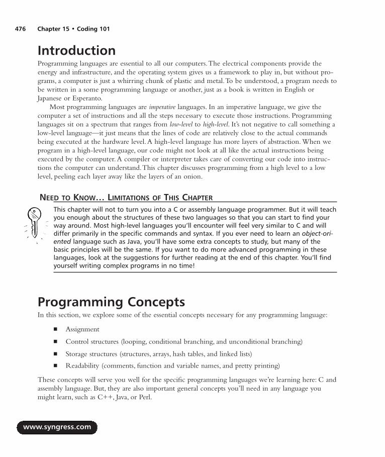
IntroductionProgramming languages are essential to all our computers.The electrical components provide theenergy and infrastructure, and the operating system gives us a framework to play in, but without pro-grams, a computer is just a whirring chunk of plastic and metal.To be understood, a program needs tobe written in a some programming language or another, just as a book is written in English orJapanese or Esperanto.
Most programming languages are imperative languages. In an imperative language, we give thecomputer a set of instructions and all the steps necessary to execute those instructions. Programminglanguages sit on a spectrum that ranges from low-level to high-level. It’s not negative to call something alow-level language—it just means that the lines of code are relatively close to the actual commandsbeing executed at the hardware level.A high-level language has more layers of abstraction. When weprogram in a high-level language, our code might not look at all like the actual instructions beingexecuted by the computer.A compiler or interpreter takes care of converting our code into instruc-tions the computer can understand.This chapter discusses programming from a high level to a lowlevel, peeling each layer away like the layers of an onion.
NEED TO KNOW… LIMITATIONS OF THIS CHAPTER
This chapter will not to turn you into a C or assembly language programmer. But it will teachyou enough about the structures of these two languages so that you can start to find yourway around. Most high-level languages you’ll encounter will feel very similar to C and willdiffer primarily in the specific commands and syntax. If you ever need to learn an object-ori-ented language such as Java, you’ll have some extra concepts to study, but many of thebasic principles will be the same. If you want to do more advanced programming in theselanguages, look at the suggestions for further reading at the end of this chapter. You’ll findyourself writing complex programs in no time!
Programming ConceptsIn this section, we explore some of the essential concepts necessary for any programming language:
Assignment
Control structures (looping, conditional branching, and unconditional branching)
Storage structures (structures, arrays, hash tables, and linked lists)
Readability (comments, function and variable names, and pretty printing)
These concepts will serve you well for the specific programming languages we’re learning here: C andassembly language. But, they are also important general concepts you’ll need in any language youmight learn, such as C++, Java, or Perl.
www.syngress.com
476 Chapter 15 • Coding 101
287_HRD_HACK_15.qxd 1/14/04 9:06 AM Page 476
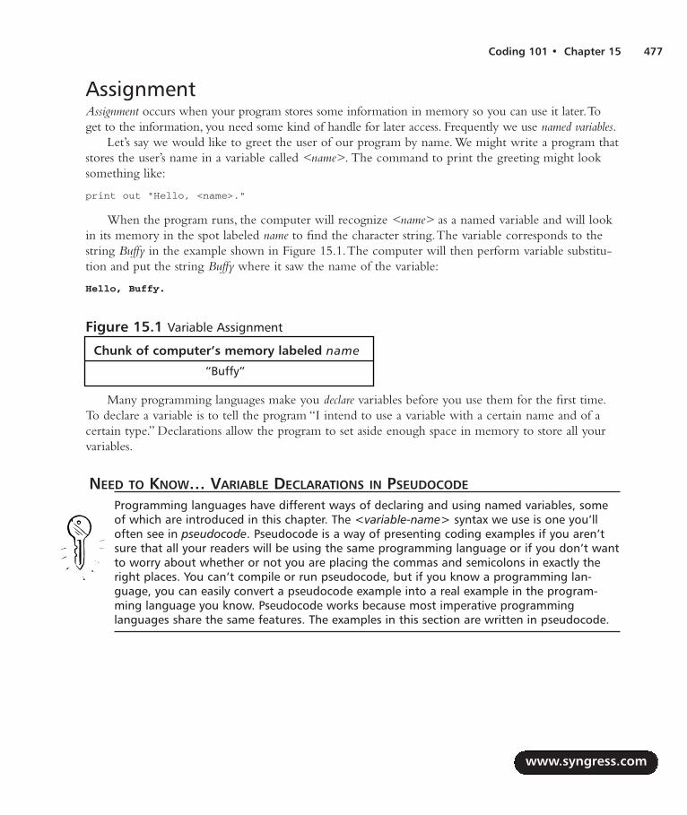
Coding 101 • Chapter 15 477
AssignmentAssignment occurs when your program stores some information in memory so you can use it later.Toget to the information, you need some kind of handle for later access. Frequently we use named variables.
Let’s say we would like to greet the user of our program by name. We might write a program thatstores the user’s name in a variable called <name>. The command to print the greeting might looksomething like:
print out "Hello, <name>."
When the program runs, the computer will recognize <name> as a named variable and will lookin its memory in the spot labeled name to find the character string.The variable corresponds to thestring Buffy in the example shown in Figure 15.1.The computer will then perform variable substitu-tion and put the string Buffy where it saw the name of the variable:
Hello, Buffy.
Figure 15.1 Variable Assignment
Chunk of computer’s memory labeled name
“Buffy”
Many programming languages make you declare variables before you use them for the first time.To declare a variable is to tell the program “I intend to use a variable with a certain name and of acertain type.” Declarations allow the program to set aside enough space in memory to store all yourvariables.
NEED TO KNOW… VARIABLE DECLARATIONS IN PSEUDOCODE
Programming languages have different ways of declaring and using named variables, someof which are introduced in this chapter. The <variable-name> syntax we use is one you’lloften see in pseudocode. Pseudocode is a way of presenting coding examples if you aren’tsure that all your readers will be using the same programming language or if you don’t wantto worry about whether or not you are placing the commas and semicolons in exactly theright places. You can’t compile or run pseudocode, but if you know a programming lan-guage, you can easily convert a pseudocode example into a real example in the program-ming language you know. Pseudocode works because most imperative programminglanguages share the same features. The examples in this section are written in pseudocode.
www.syngress.com
287_HRD_HACK_15.qxd 1/14/04 9:06 AM Page 477

If our name greeting example were written in C, it would appear as follows:
#include <stdio.h>
main()
/* Initialize the user’s name */
char name[] = "Buffy";
/* Print the user’s name */
printf("Hello, %s\n", name);
Control Structures It would be pretty difficult to write a program if we had to tell the computer every single instructionand exactly when we wanted the computer to implement that instruction. Say we wanted to write aprogram to display the words “Hello, world” on the computer screen. If we had to tell the computerevery instruction, our program might look something like this:
Print out "H".
Move the cursor right a few pixels.
Print out "e".
Move the cursor right a few pixels.
Print out "l".
...
The same program would be written in C as follows:
#include <stdio.h>
main()
printf("H");
printf("e");
printf("l");
...
www.syngress.com
478 Chapter 15 • Coding 101
287_HRD_HACK_15.qxd 1/14/04 9:06 AM Page 478

Coding 101 • Chapter 15 479
Even this simple program assumes that the computer already knows how to display each letter onthe screen! To make programming easier, languages use assignment, looping, conditional branching,and unconditional branching.
LoopingLooping allows you to execute the same lines of code multiple times. Perhaps you want to say “Hello,world” five times.You could write the line of code print out ‘hello, world’ five times, or you could use alooping structure to tell your program to run your one line of code multiple times:
five times, print out 'hello, world'
hello, world
hello, world
hello, world
hello, world
hello, world
This program would be written in C as follows:
#include <stdio.h>
main()
int counter; /* initialize the counter to integer */
for ( counter = 0; counter < 5 ; counter++ )
printf("hello, world\n");
www.syngress.com
287_HRD_HACK_15.qxd 1/14/04 9:06 AM Page 479

Conditional BranchingConditional branching allows you to tell your program what to do if certain conditions are met. Forexample, we might write a program that says goodbye to you at the end of the day.At 5:00 P.M.Monday through Thursday, we want our program to say “Goodnight. See you tomorrow!” But at 5:00P.M. Friday, we want our program to say “Have a great weekend!” Our pseudocode might look some-thing like:
If today is Monday, Tuesday, Wednesday, or Thursday, then print out "Goodnight. See
you tomorrow!"
Or:
If today is Friday, then print out "Have a great weekend!"
This program would be written in C as follows:
#include <stdio.h>
main()
char weekday;
/*
* Some code goes here to set "weekday" based on the current day
*/
switch (weekday)
case 'M', 'T', 'W', 'R':
printf("Goodnight. See you tomorrow!\n");
break;
case 'F':
printf("Have a great weekend!\n");
break;
; /* Finished with the switch statement */
The most common conditional branching structures are if/then/else statements like the one inthis example and conditionals built into loops (which execute some lines of code until the followingconditions are met).
www.syngress.com
480 Chapter 15 • Coding 101
287_HRD_HACK_15.qxd 1/14/04 9:06 AM Page 480

Unconditional BranchingUnconditional branching allows you to tell your program what to do when a certain line is reached,without any conditions. Some blocks of code might be run many times. Unconditional branchingallows you to write that frequently used code in some convenient location outside the main body ofyour program, storing it as a procedure or function. When you need to execute that block of code, youcan branch to that block wherever it exists.
Here’s an example:
<planet> = earth [comment: assignment]
for five times
print out "hello <planet>"
finish loop [comment: looping]
call function <day> [comment: unconditional branching]
begin function <day>
if today is monday
print out "happy monday"
else
print out "aren't you glad it isn't monday?"
finish if [comment: conditional branching]
finish function <day>
If run on a Monday, this program will display:
hello world
hello world
hello world
hello world
hello world
happy monday
This might seem a bit complicated. On the other hand, this program would be written in C asfollows:
#include <stdio.h>
main()
int counter; /* declaration */
char planet[] = "earth"; /* declaration & assignment*/
char today; /* declaration */
void day(); /* function declaration */
for ( counter = 0; counter < 5; counter++ )
www.syngress.com
Coding 101 • Chapter 15 481
287_HRD_HACK_15.qxd 1/14/04 9:06 AM Page 481
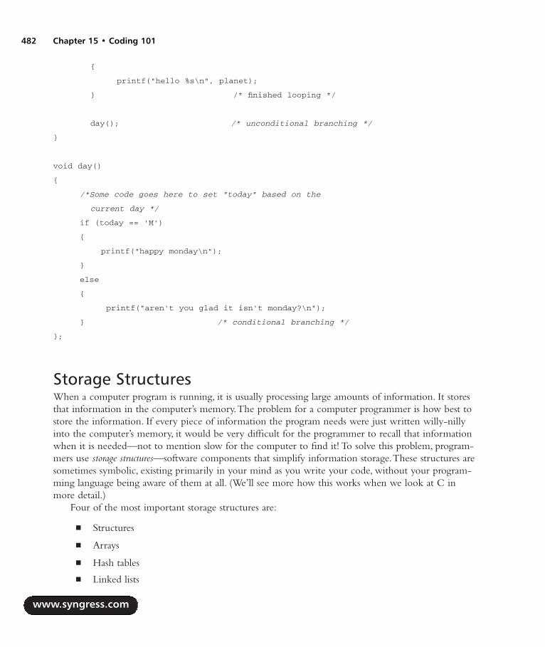
printf("hello %s\n", planet);
/* finished looping */
day(); /* unconditional branching */
void day()
/*Some code goes here to set "today" based on the
current day */
if (today == 'M')
printf("happy monday\n");
else
printf("aren't you glad it isn't monday?\n");
/* conditional branching */
;
Storage StructuresWhen a computer program is running, it is usually processing large amounts of information. It storesthat information in the computer’s memory.The problem for a computer programmer is how best tostore the information. If every piece of information the program needs were just written willy-nillyinto the computer’s memory, it would be very difficult for the programmer to recall that informationwhen it is needed—not to mention slow for the computer to find it! To solve this problem, program-mers use storage structures—software components that simplify information storage.These structures aresometimes symbolic, existing primarily in your mind as you write your code, without your program-ming language being aware of them at all. (We’ll see more how this works when we look at C inmore detail.)
Four of the most important storage structures are:
Structures
Arrays
Hash tables
Linked lists
www.syngress.com
482 Chapter 15 • Coding 101
287_HRD_HACK_15.qxd 1/14/04 9:06 AM Page 482

NEED TO KNOW… A NOTE ABOUT STORAGE STRUCTURES, C, AND ASSEMBLY LANGUAGE
Hash tables and linked lists are high-level data structures and are not built in to any standardimplementations of C or assembly language. Many C programs include homegrown implemen-tations of linked lists and hash tables (which are fairly easy to write) because they are so veryuseful. We can’t teach you the details of every implementation, but we can teach you enoughabout the basics to recognize them and to know how to use them when you see them.
StructuresBefore we go into details about the various storage structures, let’s start with the miscellaneous storagestructure: the appropriately named structure (see Figure 15.2). Structures (sometimes called records) areconglomerations of different types of data. For example, a pizza recipe structure might hold:
An array (illustrated in Table 15.1) of ingredients to make the crust
A linked list (as illustrated in Table 15.4) of ingredients to make the toppings
One bowl
One oven
Structures are handy mostly as a logical organization aid. In a large and complex program, youmight use a structure to make it easier for you to remember what data should be treated as part ofone logical unit.
www.syngress.com
Coding 101 • Chapter 15 483
Figure 15.2 A Pizza Recipe Structure, With Elements We’ll Explore in More Detail Shortly
Structure: Pizza Recipe
BOWL
Flour Salt Yeast Water
Sauce Cheese Mushrooms Olives
OVEN
287_HRD_HACK_15.qxd 1/14/04 9:06 AM Page 483

ArraysOne way of storing data is in an array.An array is like a long row of post-office boxes. Each post-office box has a unique number on its door and contains mail for one person or family. When a post-office customer wants to check her mail, she looks in the box with her number on the door. Her mailis always stored in that box.
In an array, the computer cordons off an area of memory that holds the information being stored,just like the post-office wall is filled with post-office boxes. Each virtual post-office box is called anarray element. Each element stored in the array is indexed by a number. If you want to retrieve theinformation stored in the fourth chunk of the array, for example, you would request the informationtelling the computer the array’s name and the chunk you want to retrieve. For example, your arraymight be called greetings and contain all the different ways to say hello.An example of array greetings isshown in Table 15.1.
Table 15.1 The Sample Array greetings
The Array greetings
element 1 helloelement 2 bonjourelement 3 zdravstvuiteelement 4 hola
Now greetings(4) contains the string hola.Your pseudocode program might say:
print to screen greetings(4) + " world!"
which would produce the output:
hola world!
NEED TO KNOW… A NOTE ABOUT NUMBERING
In most programming languages, numbering actually starts at 0, not at 1. A list with fourelements will have those elements numbered 0, 1, 2, and 3. So the array in Table 15.1 willactually look more like the array shown in Table 15.2.
www.syngress.com
484 Chapter 15 • Coding 101
287_HRD_HACK_15.qxd 1/14/04 9:06 AM Page 484
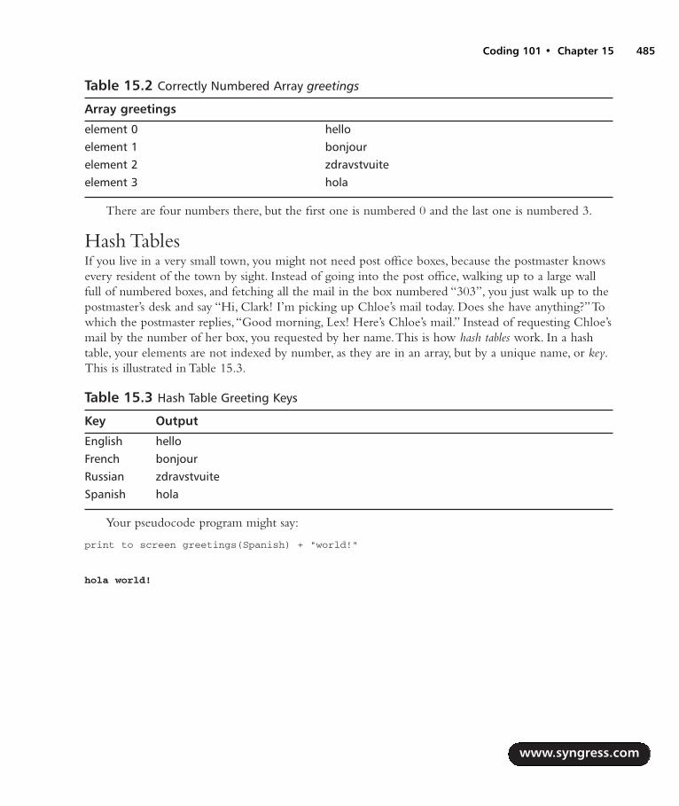
Table 15.2 Correctly Numbered Array greetings
Array greetings
element 0 helloelement 1 bonjourelement 2 zdravstvuiteelement 3 hola
There are four numbers there, but the first one is numbered 0 and the last one is numbered 3.
Hash TablesIf you live in a very small town, you might not need post office boxes, because the postmaster knowsevery resident of the town by sight. Instead of going into the post office, walking up to a large wallfull of numbered boxes, and fetching all the mail in the box numbered “303”, you just walk up to thepostmaster’s desk and say “Hi, Clark! I’m picking up Chloe’s mail today. Does she have anything?”Towhich the postmaster replies,“Good morning, Lex! Here’s Chloe’s mail.” Instead of requesting Chloe’smail by the number of her box, you requested by her name.This is how hash tables work. In a hashtable, your elements are not indexed by number, as they are in an array, but by a unique name, or key.This is illustrated in Table 15.3.
Table 15.3 Hash Table Greeting Keys
Key Output
English helloFrench bonjourRussian zdravstvuiteSpanish hola
Your pseudocode program might say:
print to screen greetings(Spanish) + "world!"
hola world!
www.syngress.com
Coding 101 • Chapter 15 485
287_HRD_HACK_15.qxd 1/14/04 9:06 AM Page 485

NEED TO KNOW… HASH TABLES VERSUS ARRAYS
You might ask why we don’t always use hash tables instead of arrays. After all, isn’t it easierto remember that the Spanish word for hello is stored in the box keyed with the wordSpanish than it is to remember that it’s box number 4? There are two answers to this ques-tion. First, in this example, it is easier to remember Spanish than 4. But more importantly,arrays are nearly always faster than hash tables. This speed of hash table access and arrayaccess varies among different language implementations, but it is usually much faster for thecomputer to find array elements. See the discussion of array implementation in C for anexample of why this is usually so.
Linked ListsHash tables and arrays are all well and good if you’re going to be accessing one piece of information at atime, as if you were fetching your mail from a post-office box. But maybe you need to get at your storedinformation in a particular order, first one piece, and then the next. For example, you’ve decided tomake a pizza from scratch.You need to start with flour, salt, water, and yeast, and then later add tomatosauce, cheese, mushrooms, and garlic.You have to make sure you access your ingredients in order becauseit won’t be a very good pizza if you mix the flour with the mushrooms.A linked list makes sure that youaccess the ingredients in order—a detail that it has in common with arrays.The main difference betweenan array and a linked list is that in a linked list, you can add or remove containers from your list.Remember, an array is like a wall of post-office boxes. If you are storing the ingredients for your pizzain a wall of post-office boxes, your pizza recipe might look similar to Table 15.4.
Table 15.4 Array of Pizza Ingredients
1 2 3 4 5 6 7 8
Flour Salt Water Yeast Tomato Cheese Mushrooms Garlicsauce
But what if you decide that you don’t want mushrooms on your pizza? You can take the mush-rooms out of box 7, but there’s still an empty post-office box between the cheese and the garlic.Youcan’t remove the empty space.That’s both wasteful and confusing and would lead to an arrangementsimilar to Table 15.5.
Table 15.5 Modified Array of Pizza Ingredients
1 2 3 4 5 6 7 8
Flour Salt Water Yeast Tomato Cheese Garlicsauce
www.syngress.com
486 Chapter 15 • Coding 101
287_HRD_HACK_15.qxd 1/14/04 9:06 AM Page 486
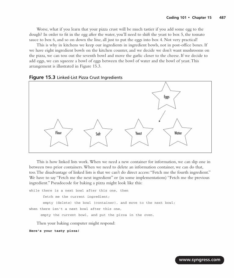
Worse, what if you learn that your pizza crust will be much tastier if you add some egg to thedough? In order to fit in the egg after the water, you’ll need to shift the yeast to box 5, the tomatosauce to box 6, and so on down the line, all just to put the eggs into box 4. Not very practical!
This is why in kitchens we keep our ingredients in ingredient bowls, not in post-office boxes. Ifwe have eight ingredient bowls on the kitchen counter, and we decide we don’t want mushrooms onthe pizza, we can toss out the seventh bowl and move the garlic closer to the cheese. If we decide toadd eggs, we can squeeze a bowl of eggs between the bowl of water and the bowl of yeast.Thisarrangement is illustrated in Figure 15.3.
This is how linked lists work. When we need a new container for information, we can slip one inbetween two prior containers. When we need to delete an information container, we can do that,too.The disadvantage of linked lists is that we can’t do direct access:“Fetch me the fourth ingredient.”We have to say “Fetch me the next ingredient” or (in some implementations) “Fetch me the previousingredient.” Pseudocode for baking a pizza might look like this:
while there is a next bowl after this one, then
fetch me the current ingredient;
empty (delete) the bowl (container), and move to the next bowl;
when there isn't a next bowl after this one,
empty the current bowl, and put the pizza in the oven.
Then your baking computer might respond:
Here’s your tasty pizza!
www.syngress.com
Coding 101 • Chapter 15 487
Figure 15.3 Linked-List Pizza Crust Ingredients
Flour Salt Yeast Water
Eggs
287_HRD_HACK_15.qxd 1/14/04 9:06 AM Page 487

ReadabilityIn order to make code maintainable—to fix its bugs and update it as time passes—you should makesure your code is as readable as possible. Programmers joke about code that is WORN (Write Once,Read Never). It’s easy to write a computer program that is completely unreadable. But unless you’retrying to win the annual International Obfuscated C Contest (a genuine contest, run since 1984,which gives prizes to the most unreadable and bizarre C program entered—archives atwww.ioccc.org/years-spoiler.html), you probably want to make sure that you can read your own codeafter you’ve written it.
CommentsAll computer languages give you the ability to write comments in the code. Comments are blocks ofthe program text that the computer does not try to run. Comments are intended for you, the pro-grammer, and anyone else who might need to read the code. Since computer languages rarely lookmuch like English, it can be difficult to look at a piece of code you’ve written after some time haspassed and understand exactly what it does. If you include comments explaining the intent of eachsignificant block of code, you’ll always be able to understand the original intent of those lines. Eachlanguage has a different way of telling the computer that some lines of text are comments and notprogram, such as the symbols # , /*, or //, but it is usually pretty easy to recognize them.An exampleof commenting is shown in Figure 15.4.
Figure 15.4 Code With Comments
while nextBowl exists /* if the next bowl isn't empty */
fetch Ingredient /* take the ingredient from the current bowl */
nextBowl /* move to the next bowl */
delete prevBowl /* put the previous, empty bowl in the sink */
when nextBowl doesn't exist /* when you're done, */
delete Bowl /* put the last bowl in the sink */
bake pizza /* and put the pizza in the oven! */
Function and Variable NamesWhen you’re writing a computer program, you’ll probably have the opportunity to assign lots of arbi-trary names to variables and functions. It’s easy to get lazy and assign function and variable names that arevery short, so you don’t have to type very much. But take a look at the program from Figure 15.4 if wereplace all the variable names with something very short and easy to type, shown in Figure 15.5.
www.syngress.com
488 Chapter 15 • Coding 101
287_HRD_HACK_15.qxd 1/14/04 9:06 AM Page 488
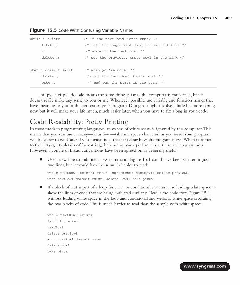
Figure 15.5 Code With Confusing Variable Names
while i exists /* if the next bowl isn't empty */
fetch k /* take the ingredient from the current bowl */
i /* move to the next bowl */
delete m /* put the previous, empty bowl in the sink */
when i doesn't exist /* when you're done, */
delete j /* put the last bowl in the sink */
bake n /* and put the pizza in the oven! */
This piece of pseudocode means the same thing as far as the computer is concerned, but itdoesn’t really make any sense to you or me. Whenever possible, use variable and function names thathave meaning to you in the context of your program. Doing so might involve a little bit more typingnow, but it will make your life much, much easier later, when you have to fix a bug in your code.
Code Readability: Pretty PrintingIn most modern programming languages, an excess of white space is ignored by the computer.Thismeans that you can use as many—or as few!—tabs and space characters as you need.Your programwill be easier to read later if you format it so that it is clear how the program flows. When it comesto the nitty-gritty details of formatting, there are as many preferences as there are programmers.However, a couple of broad conventions have been agreed on as generally useful:
Use a new line to indicate a new command. Figure 15.4 could have been written in justtwo lines, but it would have been much harder to read:
while nextBowl exists; fetch Ingredient; nextBowl; delete prevBowl.
when nextBowl doesn't exist; delete Bowl; bake pizza.
If a block of text is part of a loop, function, or conditional structure, use leading white space toshow the lines of code that are being evaluated similarly. Here is the code from Figure 15.4without leading white space in the loop and conditional and without white space separatingthe two blocks of code.This is much harder to read than the sample with white space:
while nextBowl exists
fetch Ingredient
nextBowl
delete prevBowl
when nextBowl doesn't exist
delete Bowl
bake pizza
www.syngress.com
Coding 101 • Chapter 15 489
287_HRD_HACK_15.qxd 1/14/04 9:06 AM Page 489

Introduction to CC is a runtime environment that exists on nearly every platform. For historical reasons, almost everysystem in existence can run compiled C programs. C is a platform-independent compiled language,but it has a large library of hardware-specific, low-level system calls available to help us access thehardware. On its own, C is a very small language; it doesn’t even know how to display text to thescreen! But every C installation comes with the C standard libraries, which provide the programmerwith a host of handy functions.
C is a compiled language.This means that we write the program in the English-like language thatyou’re learning here and then use another program (a compiler) to convert it into commands the com-puter can understand and execute.
NEED TO KNOW… YOUR COMPILER
Many different C compilers are available. You might be using a command-line compiler, forwhich you write your program in a text editor such as Notepad, Emacs, or vi and then compileyour program with a command such as cc myprogram.c -o myprogram.exe. You might beusing a graphical programming environment, where you write and compile your program in aneasy-to-understand window, with compilation just another menu item or button to press. Wecan’t teach you the ins and outs of the compiler you’ll be using, because they’re all different.Refer to your compiler manual for instructions on how to compile your C program.
History and Basics of CC was invented by Dennis Ritchie (based on work done by Kenneth Thompson) in the early 1970s asa language intended for programming on Thompson’s brand-new UNIX operating system. C wasstandardized into what we now know as ANSI C in the mid-1980s. For many years, C was primarilyused for programming on UNIX and its variants, but it is now a widespread standard. C and itsdescendents (including Visual C and C++) are among the most widely used programming languages.
Printing to the ScreenA C program is just a sequence of commands. Let’s start with our first program, the ubiquitous “hello,world,” which is the first program you will learn to write in almost any programming language (seeFigure 15.6).
www.syngress.com
490 Chapter 15 • Coding 101
287_HRD_HACK_15.qxd 1/14/04 9:06 AM Page 490

Figure 15.6 The Hello, World Program
#include <stdio.h>
main()
printf("hello, world\n");
Let’s break down this program.The meat of any C program, the part that runs when you executethe program, is in the main block.This main block is a special-purpose function that tells your programto begin its work here.You can see the declaration of the main block on line 3 of Figure 15.6.Thoseparentheses after the word main are required after any function and are used to pass arguments to thefunction if you need any (we’ll get to some details of function calls and argument passing soon). Inthis program, we aren’t passing any arguments to the main function, so the parentheses are present butempty.
After a function’s initial line, all statements that belong to that function are grouped together withcurly braces . In this program, those curly braces are on lines 4 and 6.Anything between those curlybraces (in this case, line 5) is part of the function. So in this program, the heart of the main block isthe command on line 5:
printf("hello, world\n");
The command printf, like main, is a function. Notice that it begins with the function name (printf)followed by zero or more arguments in closing parentheses (in this case, one argument, which is equalto the string “hello, world\n”). printf is the formatted print command. Here it is printing to the screenthe contents of its argument: the characters hello world followed by \n. In a C character string, a singlecharacter preceded by the backslash character (\) has a special meaning. \n is the C notation forprinting a new line to the screen.You can’t put a new line directly in a quoted string, for example:
"here is my first line
here is my second"
This is not valid C.To write those lines to the screen, your command would have to be:
printf("here is my first line\nhere is my second\n")
or a variant:
printf("here is my first line\n");
printf("here is my second\n");
www.syngress.com
Coding 101 • Chapter 15 491
287_HRD_HACK_15.qxd 1/14/04 9:06 AM Page 491

or:
printf("here is ");
printf("my first line\nhere is my second\n");
The separate printf commands don’t change where the new-line characters are printed on thescreen. Only the \n characters create new lines.
NEED TO KNOW… SOME INTERESTING CHARACTER STRING ESCAPE SEQUENCES
Several similar sequences cause printf to display something special to the screen. Some arevery special types of characters, such as the audible alert bell that printf sounds when giventhe character sequence \a. Most are designed simply to escape the meaning of some othercharacter (hence the name escape sequences), to allow printf to print the literal characterinstead of trying to interpret the meaning. For example, if we need to display a double quotemark (“) on the screen, we need to prevent printf from parsing the special meaning of thedouble quote mark as “here is the beginning or end of a character string.” Some of themore interesting escape sequences include:
\n newline \t horizontal tab \? question mark \’ single quote \” double quote \a alert bell
Earlier we mentioned that C doesn’t really have much complex functionality of its own anddoesn’t even know how to output characters to the screen in any simple way. Well, that’s where line 1of Figure 15.6 comes in. C has standard libraries that provide that basic functionality that is not builtinto the language.To make your final program as small as possible, you include only the standardlibraries you need into your program. Line 1 includes the standard library stdio.h, which is responsiblefor standard input and output functionality.The included library provides us with the printf function.
One last character we haven’t covered: that semicolon (;) at the end of line 5. C commands areseparated by semicolons, not by white space, so the following commands are legal:
printf("here is");
printf("my first line\nhere is my second\n");
But this next example isn’t:
printf("here is")
printf("my first line\nhere is my second\n")
www.syngress.com
492 Chapter 15 • Coding 101
287_HRD_HACK_15.qxd 1/14/04 9:06 AM Page 492

Data Types in CC is a strongly typed language.This means that the language distinguishes among the different types ofdata it can process. It’s important to recognize data types for many reasons. For one thing, your pro-gramming language needs to allocate storage for any information you intend to store.To store theinteger 8 is relatively simple; you need as much space is the computer will take to store that integer.But what if you want to store the real number 8? (To program efficiently, you’re going to use thingsyou learned in math class! Remember that integers are only the numbers -∞,...,-3,-2,-1,0,1,2,3,...,∞,but that real numbers also include numbers like 3.759.) If you want to store the real number 8 to, say,three points of precision (that is, so you can distinguish between 8.000 and 8.003), you’ll need a lotmore storage space in the computer.And if you want to be able to distinguish between 8.000 and -8.000, you’ll need even more space. So it’s important to use the right data type for your variable, oryou can rapidly run out of memory for your program.
C has only a few data types:
Int An integer.
Float A single precision floating-point number (basically, a real number).
Double A double precision floating-point number (basically, a real number with extra precision).
Char One character.
You can qualify these data types with short (if you aren’t using very large numbers and want theprogram to allocate space effectively) and long (if you are using very large numbers).You can alsoqualify the data types with signed (if it matters to you whether the numbers are positive or negative)and unsigned (if you’re not going to be using negative numbers and you want the program to allocatespace effectively). For entry-level programming, you won’t use any of these qualifiers, but you’ll wantto be able to recognize them if you see them in somebody else’s code.
If you’ve done some programming before, you might notice two types that are missing here:Booleans and character strings. Booleans (the values true and false) are usually represented in C as aspecial case of integers. Character strings are arrays of characters. We’ll talk more about how to imple-ment character strings later.
Mathematical FunctionsYou know what’s really great about computers? They know how to do arithmetic, so we don’t have to.Many basic mathematical functions are included in the language C, and to use them, you don’t need toinclude any standard libraries.A standard library called math.h provides more complex mathematicalfunctions such as sines, cosines, logarithms, powers, and the like, but you don’t need to use it for simplemathematics. Figure 15.7 displays a program that calculates the number of minutes in a day.
www.syngress.com
Coding 101 • Chapter 15 493
287_HRD_HACK_15.qxd 1/14/04 9:06 AM Page 493

Figure 15.7 Mathematical Example
#include <stdio.h>
main()
/* variable declarations */
int seconds, minutes, hours;
int total;
seconds = 60; /* number of seconds in one minute */
minutes = 60; /* number of minutes in one hour */
hours = 24; /* number of hours in one day */
total = seconds * minutes * hours; /* calculate total */
printf("there are %d seconds in one day.\n", total);
When you run this program, your computer should print out the line:
there are 86400 seconds in one day.
Let’s step through this program to see what we did.You recognize line 1—it includes the standardinput and output library. We’re using this library to get the printf command, which will print theresults of our mathematical equation. Line 3 begins the main function, and line 4 provides the curlybrace that tells the program “the lines between here and the matching curly brace belong in the mainfunction.”
The first new line we’ve seen in this program is on line 5: /* variable declarations */.This is a Ccomment: a line of the program that is there for your benefit only but is ignored by the compiler.Anything between the initial /* and the closing */ is a comment and not part of the program.Thecomment on line 5 lets us know that we are about to declare variables.
Variables in C are declared before use.A declaration, which consists of a data type and somenumber of variable names, tells the program the sort of information that is going to be stored in thatvariable. In Figure 15.7, the variables are defined in two lines:
int seconds, minutes, hours;
int total;
Because they’re all of the same type (int—that is, integers), we could have declared them all inone line:
int seconds, minutes, hours, total;
www.syngress.com
494 Chapter 15 • Coding 101
287_HRD_HACK_15.qxd 1/14/04 9:06 AM Page 494

or on four separate lines as follows:
int seconds;
int minutes;
int hours;
int total;
C doesn’t care how you lay it out, so you should use whichever method makes your code mostreadable for you.You might split conceptually—variables that all refer to one function on one line andto another function on a second line—or by any other method you like.
After you’ve declared your variables, you can assign them. Assignment gives a value of the appro-priate type to the variable you have even a declaration. In this case, the appropriate type is integer, sowe assign each variable name its initial value as follows:
seconds = 60;
minutes = 60;
hours = 24;
So before we begin the computation, the variables contain meaningful values.On line 13, the actual calculation occurs:
total = seconds * minutes * hours;
Most of these characters should be fairly familiar:
Equals sign (=) is the assignment operator, which places the results of the calculation to theright of the equals sign into the variable on the left.
The asterisk (*) says to multiply, just like you would use × in a written calculation:seconds × minutes × hours.
To add and subtract you would, predictably, use the plus sign (+) and the minus sign (-),respectively, and to divide, you would use the slash (/).
The statement on line 14 is another printf statement, but this one looks a little different. For onething, it has two arguments separated by a comma: a quoted character string and a variable name.
printf("there are %d seconds in one day.\n", total);
The printf function does more than just output simple character strings to the screen. It can docomplex output formatting.The first argument to the printf function is always a character string.Thatcharacter string can contain some number of substitution characters, each one in the format % fol-lowed by a letter. For each substitution character, the printf function takes an argument explainingwhich variable will have its contents substituted into the character string.
www.syngress.com
Coding 101 • Chapter 15 495
287_HRD_HACK_15.qxd 1/14/04 9:06 AM Page 495

In this example, the substitution character is %d.This is C for “take the value of the variable forthe corresponding argument and display it as a decimal integer.”The argument that corresponds to%d is total. In the preceding calculation, the value of total was set to 60 * 60 * 24, or 86,400. So forthis example, the function’s output will be:
there are 86400 seconds in one day.
NOTE
This nonintuitive removal of the variable from the printing string isn’t present in somehigher-level languages. In Java, for example, the preceding statement would be:
System.out.println("there are " + total + " seconds in one day.");
You might ask why we set the number of seconds in a minute, the number of minutes in anhour, and the number of hours in a day as variable values.After all, aren’t variables supposed to be,well, variable? But there are always 60 seconds in one minute, always 60 minutes in one hour, andalways 24 hours in one day.And in fact, there is a way to create a symbolic constant to hold this kind ofinformation that will never change. Instead of declaring and assigning the following variable:
int seconds;
seconds = 60;
you can define a symbolic constant:
#define SECONDS_IN_HOUR 60
Every occurrence of SECONDS_IN_HOUR will be replaced at compilation time with yourreplacement text, 60. Note that there is no semicolon completing a #define line. By convention, sym-bolic constants are written in all capital letters to distinguish them from variable names, which areconventionally some combination of upper- and lowercase letters.
Control StructuresRemember all those control structures we learned about the beginning of the chapter? Well, C cando all of those. We’ll look at two forms of looping (for loops and while loops) and two forms of condi-tional branching (if/then/else statements and switch statements). Unconditional branching in C isimplemented with function calls, which we’ll deal with in the next section.
For LoopsThe for statement is a loop that operates until a certain condition has been met.This concept is shownin Figure 15.8.
www.syngress.com
496 Chapter 15 • Coding 101
287_HRD_HACK_15.qxd 1/14/04 9:06 AM Page 496

Figure 15.8 A Sample for Loop
int i;
for ( i = 1; i <= 10; i++)
...
There are three components to the loop’s control mechanism, all stored within the parentheses.Look at the three parts of the statement in Figure 15.8, separated by semicolons. First:
i = 1
This part of the loop initializes any variables that will be used during the loop’s control. Here weare taking a variable i (which has been declared beforehand as an integer—int i;) and initializing it to1.The second part of the for loop’s control gives a test condition:
i <= 10
This test is evaluated. In this case it is asking whether or not the variable stored in i is less than orequal to 10. If it isn’t, a program exits this for loop and continues on with whenever it was doingbefore the loop was entered. If it is, the body of the loop is executed. Before we re-enter the loop andperform all this once more, we do the third step of the for loop:
i++
This step increments the counter variable we are using in the loop.This command tells C to add1 to the variable stored in i.
The first time this program runs, the variable i will be initialized to 1, the program will test to seeif 1 is less than or equal to 10, and it will discover that it is.The body of the loop will be executed,the variable i will be incremented by the statement i++ to 2, and the process will begin again.Afterthe tenth time this program runs, the variable i will be incremented to 11, and the loop will stop.
www.syngress.com
Coding 101 • Chapter 15 497
287_HRD_HACK_15.qxd 1/14/04 9:06 AM Page 497
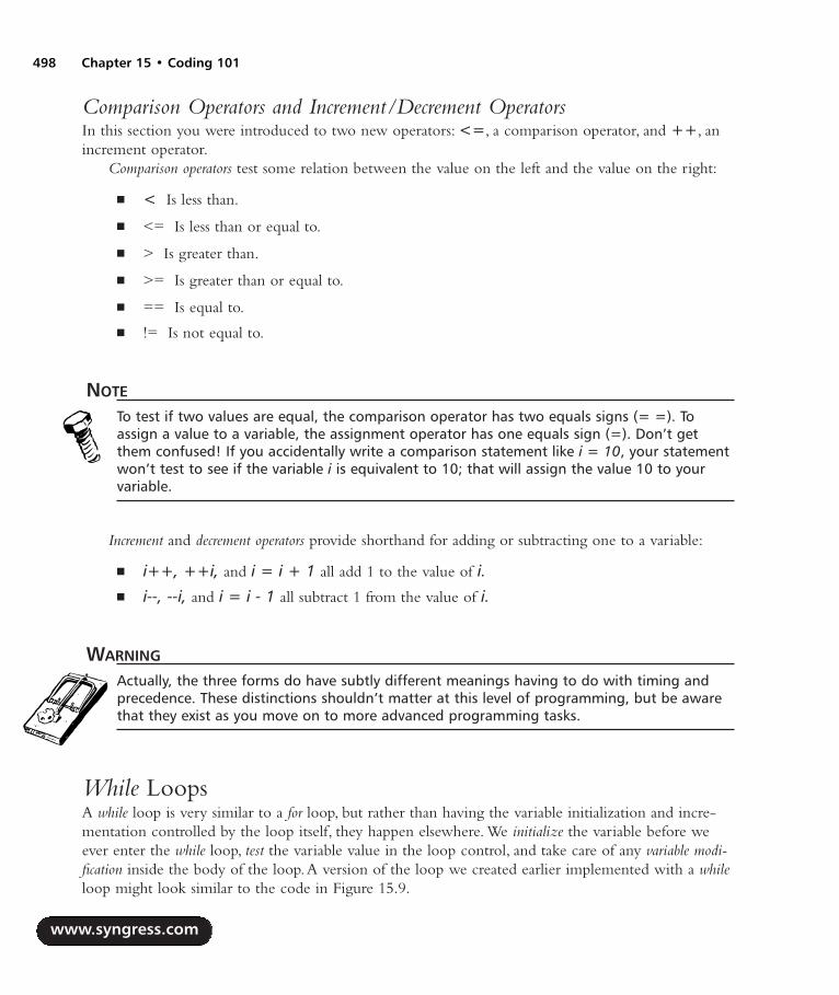
Comparison Operators and Increment/Decrement OperatorsIn this section you were introduced to two new operators: <=, a comparison operator, and ++, anincrement operator.
Comparison operators test some relation between the value on the left and the value on the right:
< Is less than.
<= Is less than or equal to.
> Is greater than.
>= Is greater than or equal to.
== Is equal to.
!= Is not equal to.
NOTE
To test if two values are equal, the comparison operator has two equals signs (= =). Toassign a value to a variable, the assignment operator has one equals sign (=). Don’t getthem confused! If you accidentally write a comparison statement like i = 10, your statementwon’t test to see if the variable i is equivalent to 10; that will assign the value 10 to yourvariable.
Increment and decrement operators provide shorthand for adding or subtracting one to a variable:
i++, ++i, and i = i + 1 all add 1 to the value of i. i--, --i, and i = i - 1 all subtract 1 from the value of i.
WARNING
Actually, the three forms do have subtly different meanings having to do with timing andprecedence. These distinctions shouldn’t matter at this level of programming, but be awarethat they exist as you move on to more advanced programming tasks.
While LoopsA while loop is very similar to a for loop, but rather than having the variable initialization and incre-mentation controlled by the loop itself, they happen elsewhere. We initialize the variable before weever enter the while loop, test the variable value in the loop control, and take care of any variable modi-fication inside the body of the loop.A version of the loop we created earlier implemented with a whileloop might look similar to the code in Figure 15.9.
www.syngress.com
498 Chapter 15 • Coding 101
287_HRD_HACK_15.qxd 1/14/04 9:06 AM Page 498

Figure 15.9 A Sample while Loop
int i;
i = 1;
while ( i <= 10 )
...
i++;
The counter variable is set before we begin the loop. When we enter the loop, we perform thetest: Is the variable less than or equal to 10? If it is, we enter the loop, perform some code in theblock, and finish incrementing the counter variable as part of the block.
If/ElseAn if statement performs conditional branching. In an if statement, we test to see if the condition istrue, do something if it is, and possibly do something else if it isn’t. We’ve done tests as part of thewhile loops and for loops, but there is no looping built into if statements.An if statement might looksimilar to that shown in Figure 15.10.
Figure 15.10 A Sample if/else Statement
int i;
...
if ( i == 1)
[A: some lines of code here]
else if ( i == 2 )
[B: only one statement can go here]
else
[C: some lines of code here]
/* end if statement */
www.syngress.com
Coding 101 • Chapter 15 499
287_HRD_HACK_15.qxd 1/14/04 9:06 AM Page 499
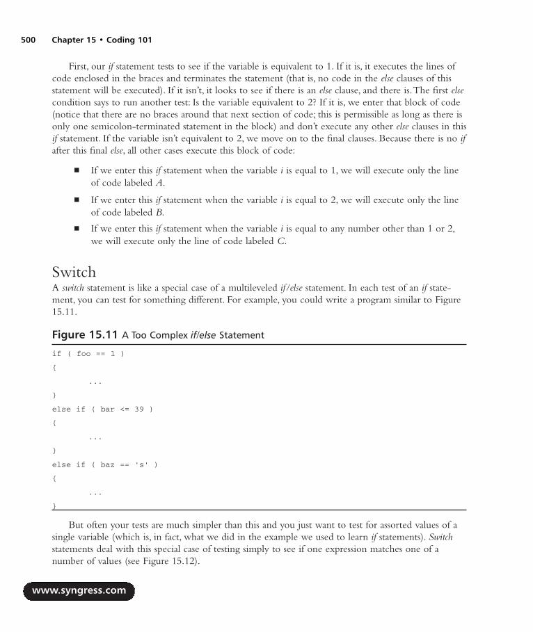
First, our if statement tests to see if the variable is equivalent to 1. If it is, it executes the lines ofcode enclosed in the braces and terminates the statement (that is, no code in the else clauses of thisstatement will be executed). If it isn’t, it looks to see if there is an else clause, and there is.The first elsecondition says to run another test: Is the variable equivalent to 2? If it is, we enter that block of code(notice that there are no braces around that next section of code; this is permissible as long as there isonly one semicolon-terminated statement in the block) and don’t execute any other else clauses in thisif statement. If the variable isn’t equivalent to 2, we move on to the final clauses. Because there is no ifafter this final else, all other cases execute this block of code:
If we enter this if statement when the variable i is equal to 1, we will execute only the lineof code labeled A.
If we enter this if statement when the variable i is equal to 2, we will execute only the lineof code labeled B.
If we enter this if statement when the variable i is equal to any number other than 1 or 2,we will execute only the line of code labeled C.
SwitchA switch statement is like a special case of a multileveled if/else statement. In each test of an if state-ment, you can test for something different. For example, you could write a program similar to Figure15.11.
Figure 15.11 A Too Complex if/else Statement
if ( foo == 1 )
...
else if ( bar <= 39 )
...
else if ( baz == 's' )
...
But often your tests are much simpler than this and you just want to test for assorted values of asingle variable (which is, in fact, what we did in the example we used to learn if statements). Switchstatements deal with this special case of testing simply to see if one expression matches one of anumber of values (see Figure 15.12).
www.syngress.com
500 Chapter 15 • Coding 101
287_HRD_HACK_15.qxd 1/14/04 9:06 AM Page 500

Figure 15.12 A Sample switch Statement
switch (foo)
case 1:
[A: some lines of code]
case 2: case 5:
[B: some lines of code]
break;
default:
[C: some lines of code]
break;
This code is running a test on the variable named foo. If the variable foo is equivalent to 2 or to 5(the line case 2: case 5:), it will execute the lines of code we’ve marked B and then break out of theswitch statement. If the variable foo is equivalent to 1 (the line case 1:), it will execute the lines of codewe’ve marked A, but because there is no break; statement, it will also execute the lines of code labeled B.Be careful of this; remember to use break! If the variable foo is equivalent to any number other than 1,2, or 5, it will execute the code labeled default, the code we’ve marked C.
NOTE
The lines of code after a “case” in a switch statement do not need curly braces around them.The switch statement itself does need curly braces.
Storage Structures
Arrays, Pointers, and Character StringsA pointer is a special kind of variable. Its job is to contain the address of another variable.The addressis the location in the computer’s memory where the second variable lives.Your house address is apointer to where on your street, in your town, you live. Knowing your address, we can come findyou. Similarly, the variable’s address tells the computer program how to find that variable in memory.
Pointers and their cousins address operators and arrays can be extremely powerful, but they can alsobe very confusing. Understanding pointers and dereferencing are the biggest hurdle in learning C.They won’t make sense all at once; don’t worry, it will sink in over time! Once you master this con-cept, you’ll be well on your way to becoming a great programmer.
www.syngress.com
Coding 101 • Chapter 15 501
287_HRD_HACK_15.qxd 1/14/04 9:06 AM Page 501
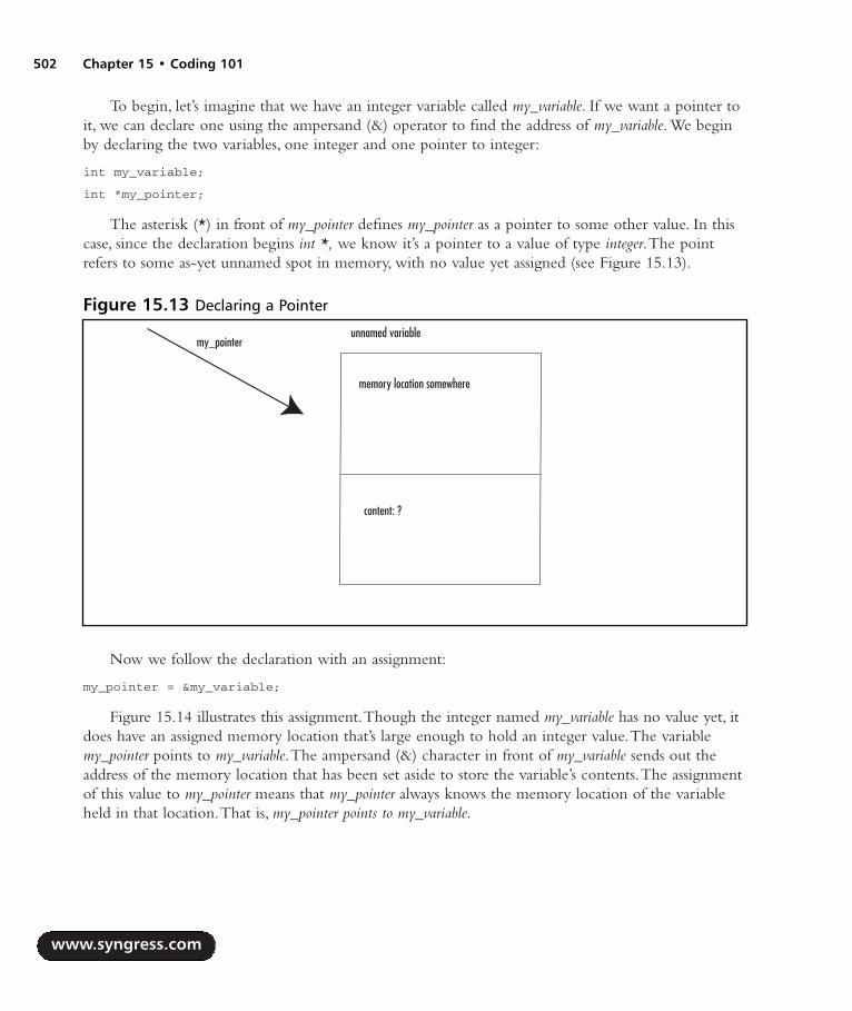
To begin, let’s imagine that we have an integer variable called my_variable. If we want a pointer toit, we can declare one using the ampersand (&) operator to find the address of my_variable. We beginby declaring the two variables, one integer and one pointer to integer:
int my_variable;
int *my_pointer;
The asterisk (*) in front of my_pointer defines my_pointer as a pointer to some other value. In thiscase, since the declaration begins int *, we know it’s a pointer to a value of type integer.The pointrefers to some as-yet unnamed spot in memory, with no value yet assigned (see Figure 15.13).
Now we follow the declaration with an assignment:
my_pointer = &my_variable;
Figure 15.14 illustrates this assignment.Though the integer named my_variable has no value yet, itdoes have an assigned memory location that’s large enough to hold an integer value.The variablemy_pointer points to my_variable.The ampersand (&) character in front of my_variable sends out theaddress of the memory location that has been set aside to store the variable’s contents.The assignmentof this value to my_pointer means that my_pointer always knows the memory location of the variableheld in that location.That is, my_pointer points to my_variable.
www.syngress.com
502 Chapter 15 • Coding 101
Figure 15.13 Declaring a Pointer
memory location somewhere
content: ?
unnamed variablemy_pointer
287_HRD_HACK_15.qxd 1/14/04 9:06 AM Page 502

The integer stored in my_variable (and pointed to by my_pointer) can then be assigned into thelocation pointed at by my_pointer. Figure 15.15 illustrates the pointer once the value has been assignedwith the command:
*my_pointer = 10;
www.syngress.com
Coding 101 • Chapter 15 503
Figure 15.14 Assigning a Pointer to an Address of Another Variable
Memory location that storesmy_variable(&my_variable)
content: Empty
my_variable
my_pointer
Figure 15.15 Pointer Assignment
Memory location that storesmy_variable(&my_variable)
content: 10
my_variablemy_pointer
287_HRD_HACK_15.qxd 1/14/04 9:06 AM Page 503
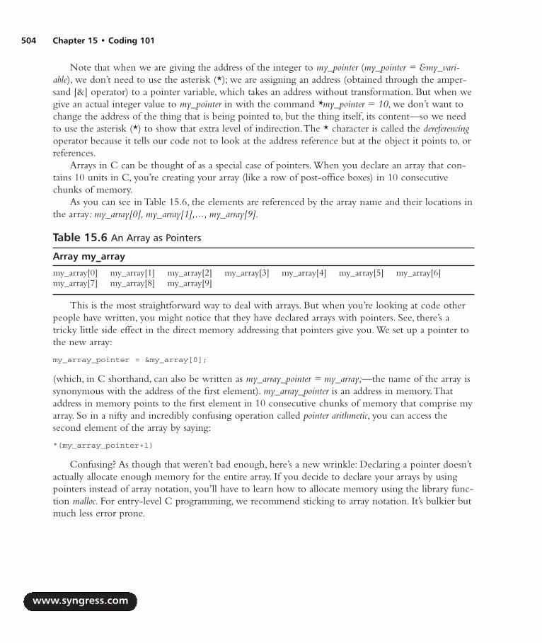
Note that when we are giving the address of the integer to my_pointer (my_pointer = &my_vari-able), we don’t need to use the asterisk (*); we are assigning an address (obtained through the amper-sand [&] operator) to a pointer variable, which takes an address without transformation. But when wegive an actual integer value to my_pointer in with the command *my_pointer = 10, we don’t want tochange the address of the thing that is being pointed to, but the thing itself, its content—so we needto use the asterisk (*) to show that extra level of indirection.The * character is called the dereferencingoperator because it tells our code not to look at the address reference but at the object it points to, orreferences.
Arrays in C can be thought of as a special case of pointers. When you declare an array that con-tains 10 units in C, you’re creating your array (like a row of post-office boxes) in 10 consecutivechunks of memory.
As you can see in Table 15.6, the elements are referenced by the array name and their locations inthe array: my_array[0], my_array[1],..., my_array[9].
Table 15.6 An Array as Pointers
Array my_array
my_array[0] my_array[1] my_array[2] my_array[3] my_array[4] my_array[5] my_array[6]my_array[7] my_array[8] my_array[9]
This is the most straightforward way to deal with arrays. But when you’re looking at code otherpeople have written, you might notice that they have declared arrays with pointers. See, there’s atricky little side effect in the direct memory addressing that pointers give you. We set up a pointer tothe new array:
my_array_pointer = &my_array[0];
(which, in C shorthand, can also be written as my_array_pointer = my_array;—the name of the array issynonymous with the address of the first element). my_array_pointer is an address in memory.Thataddress in memory points to the first element in 10 consecutive chunks of memory that comprise myarray. So in a nifty and incredibly confusing operation called pointer arithmetic, you can access thesecond element of the array by saying:
*(my_array_pointer+1)
Confusing? As though that weren’t bad enough, here’s a new wrinkle: Declaring a pointer doesn’tactually allocate enough memory for the entire array. If you decide to declare your arrays by usingpointers instead of array notation, you’ll have to learn how to allocate memory using the library func-tion malloc. For entry-level C programming, we recommend sticking to array notation. It’s bulkier butmuch less error prone.
www.syngress.com
504 Chapter 15 • Coding 101
287_HRD_HACK_15.qxd 1/14/04 9:06 AM Page 504

StringsStrings are any quoted series of characters such as:
"Hello, World!"
Character strings are a special case of array. Specifically, a string is an array of characters (termi-nated with an invisible null character, which is notated \0).
The string in Table 15.7, my_string, is an array with 14 elements.The 14th element, which weaccess from my_string[13], is the null character. It’s an important part of the string we must not forget,even though we never see it!
Table 15.7 Character Strings as Arrays
String my_string
0 1 2 3 4 5 6 7 8 9 10 11 12 13H e l l o , space W o r l d ! \0
As with any other array, a character string can be declared either with a pointer or with arraynotation.
char *pointer_to_string;
/* declares a pointer to unallocated space of a string of unknown length */
char array_of_string[10];
/* creates an array for a string of 10 characters and allocates the space */
The correct amount of space is allocated if you assign a value to the string at the same time thatyou declare it:
char *pointer_to_string = "Hello, World!";
char array_of_string[] = "Hello, World!";
Both of these declarations allocate enough space for 14 character strings and populate the stringswith the assigned value.As with any other array, we strongly recommend using array notation ratherthan pointer notation to deal with strings. It is very bulky to guess ahead of time how many charac-ters you would like to allocate, and when you become more comfortable with pointer notation youwill probably switch to that style because it is more space efficient. But for now, you will find yourcode much easier to debug if you stick with array notation.
NEED TO KNOW… WARNING ABOUT UNALLOCATED MEMORY
C will not stop you from accessing data you have not allocated. For example, you allocate anarray large enough to hold five integers:
int my_array[5];
www.syngress.com
Coding 101 • Chapter 15 505
287_HRD_HACK_15.qxd 1/14/04 9:06 AM Page 505

There is nothing in the language preventing you from later trying to grab the 23rd ele-ment of your array.
int my_number;
my_number = my_array[23];
But since you haven’t reserved that memory for the array, you have no control over whatinformation might be present in it. It might be empty, or it might be filled with garbage. Or,if that memory doesn’t belong to your program, it might crash.
Attempting to read or write unallocated memory might well be the number-one cause ofdebugging frustration, cursing at computers, and banging heads into walls for a beginning Cprogrammer. A program that looks perfectly valid will suddenly crash, presenting the message:
Segmentation violation, core dumped.
This happens so frequently that way back in 1980, Greg Boyd at Digital ComputerCorporation wrote a song about it: “The segmentation violation core dumped blues” (see thelyrics at www.netspace.org/~dmacks/internet-songbook/core-dump-blues.html). It still hap-pens. Just make sure that you allocate unassigned memory before you read it!
StructuresAfter all that complexity, structures are mercifully simple.A struct contains some number of other datatypes, all conveniently grouped together. In fact, a struct can contain other structs:
/* struct to hold some important info about a tv show */
struct tv_show
int channel; /* what channel's it on? */
char show_name[50];
char favorite_actor[50];
;
struct show_to_record
struct tv_show show_I_like;
long time;
;
Now we can declare and assign a variable of type show_to_record:
struct show_to_record IronChef;
struct show_to_record Friends;
IronChef.time = 14;
www.syngress.com
506 Chapter 15 • Coding 101
287_HRD_HACK_15.qxd 1/14/04 9:06 AM Page 506

IronChef.show_I_like.channel = 102;
IronChef.show_I_like.show_name = "Iron Chef";
IronChef.show_I_like.favorite_actor = "Fukui-San";
See how you access the elements of the struct? If you call the struct by its declared name andfollow with a dot (.) and the name of the member, you can assign a value to that member. When astruct contains a struct, you can add another dot, followed by the name of that struct’s member, and soon.You have to allocate space for all members of a struct. If you’re using pointers or arrays of unspeci-fied size, you’ll need to explicitly allocate the space for them. For now, we recommend sticking to lesscomplex data structures.
Function Calls and Variable PassingA function is a piece of code that is separately defined and can be run as many times as you like.Perhaps you’d like to reverse the order of the characters in the string several times during the runningof a program.You could write a separate function that, given the string, returns that string with itscharacters in reverse order (that is, turns Hello into olleH).The C function printf we’ve been using is anexample of a system library-provided function.
Once you’ve written a function, you need some way to pass your variable to it.There are twoways of dealing with variable data in C: call by reference and call by value.A variable that has been calledby value has a copy of its data passed to the function, not the data itself. If you make changes to thevariable in the function, you have not made those changes to the variable in the main program.
So how do we use a function to make changes that persist in the main program? The first methodis simple, if you are only changing one variable.A function returns a value ( just like any other vari-able, it can return a value of standard data type such as int, char, or the like). If you’re only modifying,say, one string, you can have a function that returns a value of type string (that is, a pointer to char-acter, or char *), as shown in Figure 15.16.
Figure 15.16 A Sample Function Declaration
/*
* this function returns a value of type pointer to char,
* or "char *"
*/
char *my_function();
This solution isn’t without drawbacks. For one thing, you might want to modify several variablesin one function. For another thing, there is a convention that many functions return integers con-taining their success status (1 if the function succeeded, 0 if it failed). If you want that functionality,you can’t return both a status integer and a modified variable, but only one.
But there’s an interesting little side effect to C’s use of pointers that gives an excellentworkaround. Let’s say the function in Figure 15.16 is passed a variable, say, a character string:
www.syngress.com
Coding 101 • Chapter 15 507
287_HRD_HACK_15.qxd 1/14/04 9:06 AM Page 507

char *my_function(char *);
This format means that my_function is a function that takes one variable, a pointer to char (presum-ably a character string), and that returns one variable, also a pointer to char. Let’s call this function:
/* since "char *" is another way of referring to "char[]",
/*either syntax can be used for declaration */
char some_string[] = "here is my string";
/* now pass it to the function */
my_function(*some_string);
We’ve learned the C uses call-by-value passing in function calls. So what is being passed to my_func-tion here? Is it a copy of the entire character array passed—“here is my string\0”? No, in fact it’s a copyof the pointer that points to the character string some_string. It’s not the same pointer, but they both pointto exactly the same place. So if you modify some_string, you actually are modifying the string itself.Thisis how C approximates call by reference.The function is being passed a value, a copy of the data, but thatvalue is a copy of a reference. In this way, you can modify any information that lives outside a functionfrom inside a function.All you need to do is pass a pointer to the variable.
System Calls and Hardware AccessSometimes your program needs to interact directly with the operating system or hardware. For thiswe have system calls.These will be different on every operating system you use, because they dependon the abilities of the individual operating system.You will probably need to include a system call-specific library file at the beginning of your program; check the documentation for your particularoperating system.
System calls are usually necessary for the kinds of low-level hardware access you need if you’rewriting a device driver. For example, you probably have access to the calls read and write, which readand write bytes directly from some file descriptor (which will allow you access to a hardware device).To usefully use these functions, you need some information about the hardware. For example, youprobably need to know the physical device’s block size—a bit of information about the physicaldevice’s logical storage mechanism.
You may also have access to some basic file systems calls: open, creat (yes, that’s spelled creat, with noe on the end), close, and unlink.These allow you to manipulate files at a level very close to the oper-ating system, instead of in the higher-level functions that are part of the standard library <stdio.h>.
You’ll need to know a little bit about the structure of your file system and the devices you meanto access if you’ll be using system calls. Since system calls are the only way to get close access to thehardware in C, you’ll almost certainly need them if you’ll be writing any direct hardware access pro-grams, such as a device driver to control a new sound card.
www.syngress.com
508 Chapter 15 • Coding 101
287_HRD_HACK_15.qxd 1/14/04 9:06 AM Page 508
SummaryC is a very small language. But this is a very small chapter. Most of what we’ve introduced here we’veonly touched on lightly, and there are many C features we haven’t had time to discuss, including suchimportant topics as:
Enums
Pointer arithmetic
Bitwise operators ( << >> & ^ | )
Logical operators ( && || ! )
Order of precedence
The standard libraries (primarily string and file functions)
Variable scope
Void types
Explicit type casting
If you plan to write a lot of C, we strongly recommend further reading in books or on the Web.C is a powerful language, and we have only introduced a small amount of what it can do.
DebuggingChances are, it won’t take you long after you’ve written your first program to discover your first bug.Everybody, from at-home hackers to computer professionals with doctorates and 30 years of experience,makes programming errors.Although it might be easy enough to find the bug in a five-line program, itcan be a lot harder as your programs get more complex. So how do you track down your bugs?
Debugging Tools Many integrated development environments come with built-in graphical debuggers.These toolsallow you to track exactly what your program is doing at any given point in time. Do you think yourprogram is having problems entering your function make_everything_work ()? Then drag the stop hereicon, which might look like a little stop sign or an exclamation mark (check your program’s docu-mentation), to the line of the program right before it enters that function. When you run the pro-gram in your graphical debugger, it will run to that point and then stop and wait for you.You can tellthe debugger to step through one line at a time, reporting the contents of variables to you as it goes.This can be a very easy way to discover that the reason your program is crashing is that you neverallocated space for that array, and you’re accessing memory that contains garbage.
If you don’t have a built-in debugger, or if you prefer the command line, there are tools that youcan use.The GNU debugger, or gdb (www.gnu.org/directory/gdb.html), is open source and freely avail-
www.syngress.com
Coding 101 • Chapter 15 509
287_HRD_HACK_15.qxd 1/14/04 9:06 AM Page 509

able on a very large number of hardware and software platforms. It works just like the graphical debug-gers, except that it operates at the command line instead of with clicking and dragging.The GNU pro-ject also supplies a graphical front end to gdb, called DDD (www.gnu.org/software/ddd), also opensource and freely available. Some programmers find this tool far more powerful, because they canquickly type any command they need rather than looking in a menu; others find it frustrating not tohave the visual aid of a graphical tool while doing complex debugging.You should use whichever toolyou find most comfortable.
The printf MethodSometimes you have a very short program, and you’re pretty sure you know where the bug is.Starting up a debugging program is cumbersome for you, and you don’t really want to bother—allyou need to know is the value of the variable this_is_right before, during, and after you enter yourfunction.This is where homemade debugging comes in.
Just tell your program to print the values of the questionable variable at various points duringyour program’s run.This doesn’t work particularly well if you’re programming graphics, but forstraight text output, it’s reasonably effective.
int foo;
printf("before I enter the function, foo is %d\n", foo");
/* Enter the function my_function_works */
my_function_works();
printf("after I enter the function, foo is %d\n", foo");
int my_function_works ()
printf("when I am in the function, foo is %d\n", foo");
...
/* Do some stuff here */
NEED TO KNOW… AN INTERESTING NOTE ABOUT PRINTF ANDUNALLOCATED MEMORY
If the reason your program is crashing is that you are accessing data from an unallocatedpointer, trying to print the data pointed to can crash your program, too! After all, if the datadoesn’t exist, it’s invisible to your debugging printf.
www.syngress.com
510 Chapter 15 • Coding 101
287_HRD_HACK_15.qxd 1/14/04 9:06 AM Page 510

What if you want to leave your debugging information in the program for later modifications,but for now, you just want it to run without output? Here’s a quick and dirty way to turn yourdebugging on and off. It relies on the C preprocessor define command. We’ll also use two new com-mands: #ifdef and #endif.These are preprocessor commands (which is the reason for the differentsyntax; don’t worry for now about the distinction between normal commands and preprocessor com-mands) and they act as simple tests. If the string after an #ifdef statement has been defined with a#define statement, all lines of code between the #ifdef and the #endif will be included in the program.If the string has not been defined with a #define statement, those lines of code will not be included inthe program.This is a little confusing, so an example could prove helpful:
#define DEBUG /* when this line exists, print out debugging information */
int foo;
#ifdef DEBUG
/* Only print this error if we are in debug mode */
printf("before I enter the function, foo is %d\n", foo");
#endif
/* Enter the function my_function_works */
my_function_works();
#ifdef DEBUG
/* Only print this error if we are in debug mode */
printf("after I enter the function, foo is %d\n", foo");
#endif
int my_function_works ()
#ifdef DEBUG
/* Only print this error if we are in debug mode */
printf("when I am in the function, foo is %d\n", foo");
#endif
...
/* Do some stuff here */
Those lines that are between the #ifdef and #endif statements won’t be evaluated unless DEBUG isdefined at the beginning of the program. When you want debugging lines in your program, defineDEBUG.When you want to program to work without debugging, just remove that #define statement.
www.syngress.com
Coding 101 • Chapter 15 511
287_HRD_HACK_15.qxd 1/14/04 9:06 AM Page 511

NEED TO KNOW… A NOTE ABOUT PREPROCESSOR COMMANDS
Lines that begin with a # in C are preprocessor commands, which means that they areparsed by the compiler before anything else. (Note that in the assembly language we’ll dis-cuss, as well as in a few other languages, lines that begin with # are comments.) Becausethese lines are processed before any other parts of the code, they are evaluated in order inthe source code, from top to bottom. The preprocessor ignores function declarations andother control structures that affect the order in which your code is run.
One last note for the sake of completeness: Operating systems generally have concepts of outputstreams, primarily standard error (stderr) and standard output (stdout).The theory is that all normal outputshould go to the standard output stream, and all errors should go to the standard error stream. Usuallyboth standard output and standard error end up on your computer monitor, and when you see thetext appear, you don’t know—nor do you care—which stream you’re seeing. But if you use theappropriate output stream, it’s very easy to treat the streams differently. Perhaps you want to pipe allthe output of the program into a text file for later analysis, but you want error messages to appear onyour screen, not in the text file. Perhaps you don’t want to see errors at all.To accommodate this kindof after-the-fact output manipulation, you can use a modified version of the printf function to sendyour errors directly to standard error:
fprintf(stderr, "when I am in the function, foo is %d\n", foo");
All this debugging will be much simpler if you have used meaningful variable names, and com-mented your code extensively.A little bit more typing is a chore, but debugging a program thatdumps core for no apparent reason is much more annoying than writing a few extra lines of com-ments.
Introduction to Assembly LanguageSometimes, even a relatively low-level language such as C doesn’t get us close enough to the hard-ware.A C program can be portable between different platforms and as such it loses something in effi-ciency. In assembly language, though, every machine instruction possible on that hardware has anassembly language translation. We use assembly language rather than writing directly in machine lan-guage, because it is easier to say ADD address_1 address_2 than to say 0xbe 0x1234 0xf337. Somewould say that a pure assembly language has no instructions that don’t map directly to a machineinstruction, but we shall stay out of that philosophical battle.
Because of this strong correlation between a particular piece of hardware’s instruction set and theassembly language usable on that hardware, assembly language programs aren’t particularly portable.Aprogram you write on one system might not be in the slightest bit usable on another system. On theother hand, assembly language programs run extremely quickly and efficiently. Instead of trusting a com-piler to lay out the instructions in the most efficient manner, you can guarantee efficiency by writingthe instructions exactly as they will be run by the CPU. Moreover, your hardware may have special fea-tures that are not accessible to you from a higher-level language such as C.An assembly language pro-gram can exploit any special hardware available features to make your code as fast as possible.
www.syngress.com
512 Chapter 15 • Coding 101
287_HRD_HACK_15.qxd 1/14/04 9:06 AM Page 512

NEED TO KNOW… LIMITATIONS OF THIS CHAPTER
As you can probably guess from the previous paragraphs, which assembler you use will varybased on your hardware and operating system platform. But even on any given platform, thereare many different assembly language implementations you can use. On Intel, for example, youcan use such assembly languages as A386, GNU as, HLA, SpAsm, and MASM. Some of theseare relatively high level, offering features that we think of as belonging to high-level program-ming languages, such as if/else statements and while loops. Others are very simple, offeringnot much above the level of the hardware. We don’t know which assembler is best for you; wedon’t know your platform or where you fall on the complexity versus power seesaw. For thischapter, we focus on simple features and give examples using the low-level GNU assembler, as,for the Intel 80386 processor. GNU as has a simple little-level instruction set, is open source,and is freely available with all Linux distributions. Keep in mind that any code you write willhave to be ported to the assembly language you choose.
Components of an Assembly Language StatementAn assembly language statement has four components:
The label
The operation
The operands
The comments
We examine all these concepts in detail in the subsequent sections.
LabelsHave you ever done any BASIC programming with GOTOs? If you have, did somebody give you asupercilious sneer and say,“Real programmers don’t use GOTOs”? Well, now you can sneer rightback—because anybody who can program in assembly language is a real programmer, and in assemblylanguage, you use GOTOs. Oh, we call them labels, but don’t let that fool you.
If you haven’t used labels or GOTO statements before, don’t worry.The concept is very simple.Alabel records the memory address of the line of code that contains the label.At any point in the code,your program can jump to the memory address of the label:
/*
* Some assembly language code goes here.
*
* Do you recognize these lines? They're comments. In GNU as,
* any text between "/*" and the next "*/" is a comment,
* even if it appears in the middle of a line. The comment character
www.syngress.com
Coding 101 • Chapter 15 513
287_HRD_HACK_15.qxd 1/14/04 9:06 AM Page 513

* may differ (sometimes it is a semicolon (;) or a pound sign (#),
* for example), but the general format is the same. These lines
* will not be translated into machine language.
*/
my_label: /* The label is the word and colon at line's start */
movl $1, %eax /* Don't worry about what this assembly language */
/* command means for now. */
/* More random assembly language code goes here. */
jmp my_label /* now the program will loop back to that label, so */
/* the next line of code it executes will be */
/* "movl $1, %eax" */
If all you can do is loop under any conditions back to the label, this program will just make end-less circles back and forth between my_label and the command jmp my_label. But even low-levelassembly languages provide simple conditionals. In GNU as, you can base the decision whether tomake the jump on the output of a comparison, as you can see in Table 15.8.
Table 15.8 GNU as Jump Commands
GNU as Command Function
cmpl value_1 value_2 This as statement compares two values and stores acomparison based on the result. It can be followedby a jump command, which will make a decisionbased on the results of the comparison.
je label Jump to label if value_1 equals value_2.jg label Jump to label if value_2 is greater than value_1.jge label Jump to label if value_2 is greater than or equal to
value_1.jl label Jump to label if value_2 is less than value_1.jle label Jump to label if value_2 is less than or equal to
value_1.jmp label Jump to label no matter what. This statement does
not need to be preceded by the comparison.
www.syngress.com
514 Chapter 15 • Coding 101
287_HRD_HACK_15.qxd 1/14/04 9:06 AM Page 514

Operations Two sorts of operations are possible in assembly language.The first sort maps directly to machine lan-guage instructions (opcodes) and is translated directly into machine language by the assembler.Thesecond sort of operation is a meta-command, a command that tells the assembler to do something,instead of telling the computer to do something. In GNU as, the second sort of operation is alwayspreceded by a dot (.) character.This is good shorthand to remember. Even though we haven’t intro-duced either command to you, you know that .int is a command directly to the assembler and popltranslates to a machine instruction. ( Just so you know, .int reserves storage for some number of inte-gers, and popl pops the top value of the stack.)
OperandsFirst, a bit of terminology:An operand is the object of an operation. In the following equation thenumbers 3 and 5 are both operands (and the + is the operator):
3 + 5 = ?
The C variables often act as special cases of operands. In the C statement, the number 4.0 and thevariable my_number are both operands:
my_answer = my_number / 4.0;
When you read about operands with assembly languages, for all practical purposes you’re readingabout variable assignment. It’s good to know this bit of terminology, though, because your documen-tation authors might be avoiding the term variable; in low-level assembly languages, the use of storedinformation is different enough from storage in high-level languages that some people prefer not touse the term.
We learned in the C section of this chapter that different kinds of data take up different amountsof space. In GNU as, we declare the data by type in order to guarantee enough space.
The possible data types are:
byte For a single byte of computer memory.
int For an integer between 0 and 65535.
long For an integer between 0 and 4294967295.
ascii For one or more characters.
The data storage is declared in the special section of the assembly language program, which is ini-tiated with a statement to the assembler:
.section .data
Next then the storage itself is declared, with another command to the assembler:
.ascii "Hello, world\0"
www.syngress.com
Coding 101 • Chapter 15 515
287_HRD_HACK_15.qxd 1/14/04 9:06 AM Page 515

In C, character strings were automatically terminated with the null character (\0). In assemblylanguage, you’ll need to add that terminating character by hand.
Sample ProgramThe best way to understand assembly language is to see a little bit of it. Here’s a simple program thatdoes a little bit of addition:
/* addition.exe */
/*
* sample assembly language program in GNU as
*
* adds together the numbers "3" and "17"
*/
/* Data section. We're not using any variables here -- just holding
* the arguments from the command line in registers, so this
* section is blank. */
.section .data
/* Text section. This is the commands of the program. */
.section .text
/* .globl defines a label which has to exist even from outside the program.
* "_start" is a special-purpose label which tells the program that this is
* the beginning, similar to "main()" in C. */
.globl _start
_start:
pushl $17 /* push the number 17 onto the top of the stack */
/* the stack is the part of memory which is currently */
/* being used, like a stack of index cards space are*/
pushl $3 /* push the number 3 onto the top of the stack. */
/* now 3 is on top, with 17 beneath it. */
www.syngress.com
516 Chapter 15 • Coding 101
287_HRD_HACK_15.qxd 1/14/04 9:06 AM Page 516

popl %eax /* pop the top of value on the stack (3) -- that is, */
/* remove it from the stack, and put it in the */
/* temporary register "%eax" */
popl %ebx /* pop the top of value on the stack (17) -- that is, */
/* remove it from the stack, and put it in the */
/* temporary register "%ebx" */
addl %eax, %ebx /* add together the two numbers, and store the result */
/* in the second temporary register, %ebx */
movl $1, %eax /* in Linux, this is the kernel's system call */
/* to exit the program. When the program exits, */
/* whatever value is stored in register %ebx */
/* will be the return value of the program. */
/* because of our addl command, the value stored */
/* in %ebx is the sum of 3+17 */
int $0x80 /* this runs the software interrupt responsible */
/* for telling the kernel to exit */
After we run this program, we can test the return value of the program to find out the sum of thetwo numbers.As you might guess from looking at the program, we made this somewhat more com-plex than it needed to be. We didn’t need to push 3 and 17 onto the stack, then pop them both offagain in order to add them together. We could have just stored the two numbers directly into thetemporary registers. But the purpose of the example was to give you a taste of assembly language.
NEED TO KNOW… STACK TRICKINESS
The top of the stack is in reality the bottom of the stack. Yes, we know, that makes no sense.After all, both “top” and “bottom” are just fake names—what do they really mean in a com-puter’s memory? It’s not like there is gravity in the computer defining what is “top” andwhat is “bottom.” What these terms mean is that if you think of memory addresses ashaving higher numbers at the top and lower numbers at the bottom, the stack grows down-ward, as illustrated in Table 15.9.
www.syngress.com
Coding 101 • Chapter 15 517
287_HRD_HACK_15.qxd 1/14/04 9:06 AM Page 517

Table 15.9 Stack Direction
Memory That Holds the Stack Stack Sitting in Memory
Address 22 First entry placed into stackAddress 18 Second entry placed into stackAddress 16 Third entry placed into stackAddress 12 Current top of stackAddress 8 XAddress 4 XAddress 0 X
If we now choose to place another entry in the stack, it will go to address 8. So if weneed to manually manipulate the stack pointer (stored in register %esp), adding a new entryto the stack means subtracting from the value of the stack pointer.
SummaryThe basis of assembly language is simple to learn. However, learning how to do something with it—that is a whole new kettle of fish. It’s very easy to manipulate registers, but how do you know whichmemory address on your computer will pop up a dialog box on Windows?
In general, we don’t use assembly language unless we need to manipulate hardware we can’taccess with high-level languages or to accelerate a particularly slow section of code.
Additional ReadingIf you are interested in learning more about any of the topics in this chapter, we recommend the following books:
Structured Computer Organization, fourth edition, by Andrew S.Tannenbaum(Prentice-Hall, 1998) Concepts of computer internals—very important if you’ll be doinglots of assembly programming.
A Book on C, by Al Kelley and Ira Pohl (The Benjamin/Cummings PublishingCompany, 1995)
C Programming Language, second edition, by Brian W. Kernighan and DennisRitchie (Prentice Hall, 1988)
The Art of Assembly Language, by Randall Hyde (No Starch Press, 2003) Focuses onthe high-level HDL.
Programming from the Ground Up, by Jonathan Bartlett (www.nongnu.org/pgubook)Focuses on the GNU assembly language.
LinuxAssembly.org: http://linuxassembly.org/ Links to online tutorials and resources.
www.syngress.com
518 Chapter 15 • Coding 101
287_HRD_HACK_15.qxd 1/14/04 9:06 AM Page 518

519
IndexNumerals and Symbolsτ (time constant, tau), 28Ω (resistance symbol, omega), 23802.11 protocol
books and articles, 346description, 324products and tools, 346–347user groups, 345–346see also Access point, installing Linux in;
Network interface cards (NICs), wireless802.11d bridging, 338
AAC (alternating current), 21–22Access point, Dell 1184
description, 338–339explanation of hack, 345file system, 342preparation, 339processes, running, 343–344root access, 340System Configuration Table, 340–342Telnet daemon, 339
Access point, installing Linux inexplanation of hack, 338image file (.IMG) size, 335OpenAP software (Instant802), 332–333powering up, 338preparation, 333–334source code, 334–335SRAM card, 333, 335–338tools, 334upgrades, 335, 337
Access points, U.S. Robotics USR 2450, 333,335
Activision games, 227–228ADB (Apple Desktop Bus) cables, 288
Addtron AWS-100 access points, 333Adjustable power supplies, 9AIR-PCM35x and AIR-LMC35x (Cisco) cards,
325Airshare users group, 345Airsnort WEP key cracker, 346All-in-Wonder Radeon 9700 Pro (ATI), 157,
173–174Alloy, ChipQuik, 38–39Alternating current (AC), 21–22Amateur radio, 324American Standard Code for Information
Interchange (ASCII), 16–18Amperes (amps), 20–21Analog multimeters, 9Antek Semiconductor 93LC46, 64Antenna connector, external. see Network
interface cards (NICs), wirelessAntennas, Pringles-can, 325Anti-static mats, 4, 90Anti-static wrist strap, 90, 298–299Apple Computers
iTunes, 351, 390Mac OS, 167–168MacTV, 168see also iPod; Macintosh computers
Apple Desktop Bus (ADB) cables, 288AppleDesign book, 112Applefritter Forums, 145–147ARM processor documentation, 450Arrays, 484–486, 501–504Art of Assembly Language book, 518The Art of Electronics book, 41ArTile Micro TX79 System-on-a-Chip (SoC)
processors, 317–318ASCII (American Standard Code for
Information Interchange), 16–18Assembly language
data types, 515description, 512jumps, 514
287_HRD_Hack_index.qxd 1/24/06 9:46 AM Page 519

520 Index
labels, 513–514operands, 515–516operations, 515sample program, 516–517stacks, 517–518strings, 516
Assignment, 477–478Atari 8-bit computer
Apple Desktop Bus (ADB) cables, 288Commodore 1702 monitor, 288composite video/audio cable, 288explanation of hack, 289monitor connector pinout, 285preparation, 281–282S-Video and composite cables, 280–287tools, 282
Atari 2600 Video Computer System (VCS)Apple Desktop Bus (ADB) cables, 288composite/S-Video modifications, 242–243explanation of hack, 223history, 200left-handed joystick modification, 202–207Nintendo Entertainment System (NES) control
pad, 207–214preparation, 203, 207–208, 216stereo audio output, 214–223tools, 203, 208, 216
Atari 5200 SuperSystemblue LED modification, 250–256composite/S-Video modifications, 290explanations of hacks, 256, 279history, 201, 249–250paddle, removing, 258–260paddle controller, building, 260–266paddle from 2600, 256–268preparation, 257–258, 269–270references, 244switchbox, four-port, 268–279tools, 258, 270uncomfortable controller design, 243VCS cartridge adapter, 228, 290
Atari 7800Apple Desktop Bus (ADB) cables, 288blue LED modification, 223–30compatibility with 2600 games, 229–232composite/S-Video modifications, 243Development Operating System (DevOS),
243–244explanations of hacks, 227–228, 236–237games, copying to PC, 243–244history, 201–202Nintendo Entertainment System (NES) control
pad, 243power-supply plug retrofit, 237–242preparation, 223–224, 229–230, 233, 238references, 244–245Sega controller modification, 243tools, 224, 229, 233, 238voltage regulator replacement, 232–236
Atari personal computers, history of, 248–250Atari-related Web sites, 244ATI
All-in-Wonder Radeon 9700 Pro, 157,173–174
Launchpad, 178Remote Wonder, 173, 175–176, 184software versions, 175
ATrpms, 194, 198
BBacklight color of telephone, changing
case, opening, 395–397components, removing, 397–399explanation of hack, 404–405LED power, adjusting, 402–403LEDs, replacing, 400–402preparation, 393–395reassembly, 403–404see also Light-emitting diodes (LEDs)
Ball Grid Array (BGA), 32
287_HRD_Hack_index.qxd 1/24/06 9:46 AM Page 520

Index 521
Ballblazer game, 201Barcode scanner. see CueCat barcode scannerBarcode types, 73–74Bardeen, John, 30Barred base stations, 414–415Base input current (IB), 31Base stations, barred, 414–415Base voltage (VB), 30Basic device theory, 23–33Battery designators and symbols, 19Bay Area Wireless Users Group, 345B&C ComputerVisions, 245Best Electronics, 245Beyond Logic Web site, 42BGA (Ball Grid Array), 32Bits
drill, 6security driver, 7
Bits, bytes, and nibbles, 14–18Blacksphere, Project, 416Block devices, 464–466Block diagram of CueCat, 75Blue Ice G4 Web site, 146BlueCube Web site, 146BNC connector, 327, 331A Book on C book, 518Books
802.11 protocol, 346AppleDesign, 112Art of Assembly Language, 518The Art of Electronics, 41A Book on C, 518C Programming Language, 518Digital Logic and Computer Design, 41electrical engineering, 41Electronic Instrument Design, 41Fundamental Electrical & Electronic Principles, 41Getting Started with Windows Drivers, 466Linux Device Drivers, 466Modern Operating Systems, 462, 473
Piloting Palm:The Inside Story of Palm,Handspring, and the Birth of the Billion-DollarHandheld Industry, 418
Programming from the Ground Up, 518Radio Shack, 41Structured Computer Organization, 518VxWorks: Device Drivers in a Nutshell, 466
BOOT.ELFchoosing, 313troubleshooting, 314
Branchingconditional, 480unconditional, 481–482
Brattain, Walter, 30Bridging, 802.11d, 338Brunn, Lukasz, 322bsd-airtools program, 346bttv drivers, 192–193, 198Buffer overflow, 316Bytes, 14–18
CC language
comparison operators, 498compilers, 490control structures, 496–501data types, 493description, 490for loops, 496–497function calls, 507–508hardware access, 508history, 490if-else statements, 499–500increment/decrement operators, 498mathematical functions, 493–496operators, other, 509printing to the screen, 490–492storage structures, 501–507switch statements, 500–501
287_HRD_Hack_index.qxd 1/24/06 9:46 AM Page 521

522 Index
system calls, 508variables, passing, 507–508while loops, 498–499
C Programming Language book, 518Cable connectors, 327Cables
DAU-9P, 408–409DCT-3 flashing cables, telephone, 410DLR-3P, 409flashing, 410null-modem, 334see also Data cables, telephone
Candy Apple Web site, 147Capacitors
description, 25–28designators and symbols, 18–19
Cartridge adapter, VCS, 228, 290Case modifications, 84–85, 94–109, 146–147CCCH (Common Control Channel), 415CDex freeware CD ripper, 180Cell phone. see Telephone, Nokia 6210 GSMCell phone base stations, barred, 414–415Center punch, 7Character devices, 464–466Character strings
in assembly language, 516in C, 505–506
Charge, storing, 25Chip-on-Board (COB) packaging, 33ChipQuik SMD Removal Kit, 36–38Circuit Cellar magazine, 41Cisco AIR-PCM35x and AIR-LMC35x cards,
325Classic Computer Magazine Archive, 245Cleaning supplies, 6Clippers, wire, 7Coats, lab, 5COB (Chip-on-Board) packaging, 33Coding. see Programming conceptsCold-solder joint, 35Collector-emitter current (IC), 31
Collector voltage (VC), 30Color-coding of resistors, 23–24Comments, 488Commercial hardware hacking, 294–296Commodore 1702 monitor, 288Common Control Channel (CCCH), 415Common mistakes, 40–41Comparison operators, 498Component video signals, 289–290Components
distributors, 43electronic, 10information about, 42–43
Composite and S-Video cables, 280–287Composite and S-Video modifications, 242–243,
290Composite video and audio cable, 288Compubrick 160 Web site, 145Compubrick SE
CRT, encasing, 128–131description, 112disassembly of Mac SE, 114–119disk drive, encasing, 123–125explanation of hack, 131–132hard drive, encasing, 125–126motherboard, encasing, 126–128mouse and keyboard, covering, 121–123preparation, 112–113speaker, encasing, 120tools, 113
Conditional branching, 480Connector, external antenna. see Network
interface cards (NICs), wirelessConnectors, cable, 327Contact East, 11Control pad, Nintendo Entertainment System
(NES), 207–214Control structures, 478–482, 496–501Controller, HTPC, 167Cooling, 184Cordless drills, 6
287_HRD_Hack_index.qxd 1/24/06 9:46 AM Page 522

Index 523
Core fundamentals of electronics, 14–23Coulombs, 20–21CPU, HTPC, 165–166C.R.Q. software privacy statement, 79–80CRT, encasing, 128–131Crystal designators and symbols, 19Cube, Macintosh. see Macintosh G4 CubeCueCat barcode encoding, removing
description, 67encoding scheme, proprietary, 76–77explanation of hack, 73–75preparation, 67–68PS/2 four-screw, 68–70PS/2 two-screw, 70–71tools, 67–68USB, 72–73see also CueCat barcode scanner
CueCat barcode scannerbarcode types supported, 73–74block diagram, 75description, 49–50encoding scheme, 76–77finding, 50–51history, 48length comparison, 77memory maps, 66–67opening, 51–55orifice, 78political and legal issues, 78–81preparation, 51Serial EEPROM, 56–57, 59, 61, 64–66software and drivers, 82varieties, 49–50, 77–78Web sites, 81–82see also CueCat barcode encoding, removing;
CueCat unique identifier (UID), removingCueCat unique identifier (UID), removing
description, 55explanation of hack, 64–67preparation, 56PS/2 four-screw, 56–58
PS/2 two-screw, 58–61USB, 61–63see also CueCat barcode encoding, removing
Current, electricaldescription, 20–22forward (IF), 29limiting, 30
Current-limiting resistors, 402–405Curve, diode V-I, 29
DD-Link DWL650 Wireless network interface
card. see Network interface cards (NICs),wireless
Data, displaying in C, 490–492Data cables, telephone
cable details, 407–409description, 406Net Monitor mode, 410–415Nokia telephone models and types, 406–407
Data sheets, 42–43Data types
in assembly language, 515in C, 493
Database structure of PDAs, 449DAU-9P cable, 408–409DC. see Direct current (DC)DCT-3 flashing cables, telephone, 410Debugging
printf method, 510–512tools, 509–510
Dell 1184 access point. see Access point, Dell1184
Dell 2300 access point, 339Desk lamps, 5Desktop Macintosh hacks, 145–146Desoldering, 36–40, 400–401Development Operating System (DevOS),
243–244
287_HRD_Hack_index.qxd 1/24/06 9:46 AM Page 523

524 Index
Device drivers, 462–466Device programmers, 9Diagnostic mode, iPod, 384–386Dielectric, 25–26Digi-Key components, 11, 43Digital Antic Project, 245Digital Logic and Computer Design book, 41Digital multimeters, 8DigitalConvergence, 48
demographics, 55out of business, 50patents, 82political and legal issues, 78–81
DigitalDemographics, 80Dining philosophers problem, 461Diodes
description, 28–30designators and symbols, 19V-I curve, 29
Diodes, light-emitting. see Light-emitting diodes(LEDs)
Direct current (DC)blocking, 25description, 21–22
Discover Circuits Web site, 42Disk-check mode, iPod, 387Disk drive, encasing, 123–125Display, HTPC, 155–160Displaying data in C, 490–492Distributors, 10–11, 43Diversity mode, 325, 332DLR-3P cable, 409DLZ-3 Web site, 145Doping, 30DragonBall MC68328 microprocessors, 447Dremel tools, 5Drills and bits, 6Drivers for CueCat, 82DVD ripper, 180–184
DWL650 (D-Link) Wireless network interfacecard. see Network interface cards (NICs),wireless
Dynamic memory, 448
EEar plugs, 5Earth. see Ground (earth)eazylook, 177eBay, 50EE Circuits Archive Web site, 42EE Compendium Web site, 42EE (Emotion Engine), PS2, 302, 317–318EEPROM, Serial. see Serial EEPROM802.11 protocol
books and articles, 346description, 324products and tools, 346–347user groups, 345–346see also Access point, installing Linux in;
Network interface cards (NICs), wireless802.11d bridging, 338Electrical current. see Current, electricalElectrical tape, 6Electricity, static, 4Electro-Mavin, 51Electro Tech Online Web site, 42Electronic components, 10Electronic Instrument Design book, 41Electronics, fundamentals of, 14–23Embedded Linux Journal Web site, 474Embedded systems, 466–467Embedded.com, 473Embedtronics, 415Emitter voltage (VE), 30Emotion Engine (EE), PS2, 302, 317–318Encoding scheme of CueCat, 76–77ePanorama Web site, 42EPROM devices, 9
287_HRD_Hack_index.qxd 1/24/06 9:46 AM Page 524

Index 525
Essential tools, 4–6Etching kits for printed-circuit boards, 10Ethereal packet capturing tool, 347Eumitcom WL11000SA-N, 333Everything iPod Web site, 390Explanations of hacks
access point, Dell 1184, 345access point, installing Linux in, 338Atari 8-bit computer, 289Atari 2600 Video Computer System (VCS),
223Atari 5200 SuperSystem, 256, 279Atari 7800, 227–228, 232Compubrick SE, 131–132CueCat barcode encoding, removing, 73–75CueCat unique identifier (UID), removing,
64–67home theater PC (HTPC) on Linux, 192–197LED color of telephone, changing, 404–405Macintosh G4 Cube, 145network interface cards (NICs), wireless, 332Palm m505, 445–447Palm Pilot 1000 and 5000, 427–429Palm Pilot Professional and Personal, 433–435PlayStation 2 (PS2), 310, 314–316terabyte FireWire hard drive, 92–93, 105UFO mouse, 140
Exploit, independence, 295–296, 310–311,315–316
Exploit Installer, 314External antenna connector. see Network
interface cards (NICs)
FFairUse (FU) freeware DVD ripper, 180–184Farads, 26FBUS protocol, 407, 409, 411, 415Fedora Linux distribution, 197File systems
Dell 1184 access point, 342description, 458–459iPod, 381personal digital assistants (PDAs), 448
Files, needle, 5FireWire hard drive, terabyte. see Terabyte
FireWire hard driveFireWire port, repairing, 388–389Fitch, John, 112Flashing cables, telephone, 410Fliptop, 295Fluorescent bulbs, 5Flux, 38for loops, 496–497Formatting code, 489Forward current (IF), 29Free Networks users group, 345Frequencies,TV channel, 193Function and variable names, 488–489Functions in C
mathematical, 493–496programming, 507–508
Fundamental Electrical & Electronic Principles book,41
Fundamentals of electronics, 14–23Fuse designators and symbols, 19
GGames, Ballblazer
Activision, 227–228copying to PC, 243–244
Gammu, 407Getting Started with Windows Drivers book, 466Gloves, rubber, 5Glues, 6Gnokii, 407Goggles, 5Graphical user interfaces (GUIs), 461Graveyard Electronics, 43
287_HRD_Hack_index.qxd 1/24/06 9:46 AM Page 525

526 Index
Ground (earth) designators and symbols, 20GSM Site, Nobbi’s, 416Guide Plus+, 178–179GUIs (graphical user interfaces), 461
HHacks, explained. see Explanations of hacksHam radio, 324Handspring Visor Modification Page, Stephanie’s,
450Hard drive, encasing, 125–126Hard drive, terabyte. see Terabyte FireWire hard
driveHard drives, HTPC, 161–164Hard-to-find components, finding, 43Hardcore tools, 8–10Hardware access in C, 508Hardware stores, 10–11Hash tables, 485–486Hexadecimal (hex) format, 15–16High-voltage inverters, 102–103Hobby Lobby, 10Home Depot,The, 10Home theater PC (HTPC)
case, 160–161components, 154constraints, 155cost, 152–153CPU, 165–166description, 150display, 155–160functions, 152hard drives, 161–164operating system, 168–170optical drives, 164–165planning, 151–153remote control, 167servers and set-top boxes, 198software required, 167–170
speed considerations, 163video card, 160see also Home theater PC (HTPC) on Linux;
Home theater PC (HTPC) on WindowsHome theater PC (HTPC) on Linux
ALSA drivers, Installing, 192channel frequencies, 193explanation of hack, 192–197MPlayer, 193–194MythTV, 194–197preparation, 185–191xawtv, 193
Home theater PC (HTPC) on Windowseazylook, 177Guide Plus+, 178–179Launchpad, 178preparation, 171–175software, installing, 176
Hot-glue gun, 331HowStuffWorks Web site, 474HTPC. see Home theater PC (HTPC)HyperTerminal program, 309Hyundai Microelectronics or Hynix
SemiconductorGMS90C54-GB189 microprocessor, 70–71HMS91C7316 microprocessor, 72
II/O processor, PS2, 321IB (base input current), 31IC. see Integrated circuits (ICs)IC (collector-emitter current), 31IC Master Web site, 42Iconfactory Web site, 147IEC marking, 26–27if-else statements, 499–500IF (forward current), 29IlluminatedMac Web site, 146Image file (.IMG) size, 335
287_HRD_Hack_index.qxd 1/24/06 9:46 AM Page 526

Index 527
Impact Components, 43Imperative languages, 476Incandescent bulbs, 5Increment/decrement operators, 498Independence exploit, 295–296, 310–311,
315–316Input/output (I/O), 460Instant802 OpenAP software. see Access point,
installing Linux inIntegrated Circuit Identification (IC-ID) Web
site, 43integrated circuits (ICs), 32–33Inverters, high-voltage, 102–103iPod
battery, description, 353, 359battery replacement price, 359–360description, 350–351diagnostic mode, 384–386disk-check mode, 387file system, 381FireWire port, repairing, 388–389formatting, 381–384Linux, 388mini iPod, 351–352references, 390scroll wheel, repairing, 389Software Updater, 381–382versions, 352Windows compatibility, 381–384see also iPod battery, replacing; iPod case,
opening; iPod hard drive, upgradingiPod battery, replacing
battery types, 360–361charging, 371description, 359–360first and second generation, 361–365preparation, 360third generation, 365–370
iPod case, openingclosing, 370–371description, 353first generation, 355–356preparation, 354
second and third generation, 356–359tools, 354
iPod Hacks Web site, 390iPod hard drive, upgrading
description, 371–372disassembly, 373–375drive sizes, 371–372preparation, 372reassembly, 378–380reinstallation, 376–378removal, 375–376
iPod Home Page, 390iPodLounge Web site, 390iTunes Home Page, 390iTunes Music Store, 351iTunes software, 351, 390
JJameco, 43JBPhonetech, 416Jig saws, 8Jobs, Steve, 114Jonathan architecture, 112Joystick, left-handed, 202–207Jumps in assembly language, 514
KKaleidoscope Web site, 147Kaljevic, Dejan, 410Kenyon & Kenyon law firm, 78–79Key crackers
Airsnort, 346WEPCrack, 346
Keyboard, covering, 121–123KisMAC program, 346Knee (of a diode), 29–30Knives, X-ACTO, 5
287_HRD_Hack_index.qxd 1/24/06 9:46 AM Page 527

528 Index
LLab coats, 5Labels in assembly language, 513–514Lamps, 5Languages, 476Laptop Macintosh hacks, 146Laptops for Less store, 354, 360, 390Launchpad (ATI), 178Law firm, Kenyon & Kenyon, 78–79Left-handed joystick, 202–207libITO graphics library for PS2, 322Light-emitting diodes (LEDs)
designators and symbols, 19example, 20power, adjusting in telephone, 402–403replacing in telephone, 400–402symbol and outline, 394type codes and sizes, 393
Lighting, 5Linked lists, 486–487Linux
distributions, 169embedded (uCLinux), 469–470iPod, 388open source, 467–468references, 197Universal Serial Bus (USB) problems, 197see also Access point, installing Linux in; Home
theater PC (HTPC) on LinuxLinux Device Drivers book, 466Linux Devices Web site, 474Linux Kit, PlayStation 2, 302, 316, 322Linux USB users mailing list, 198LinuxAssembly.org, 518Lists, linked, 486–487Logo Manager tool, 411Looping, 479Lowe’s, 10
MMac OS, 167–168MacAddict Forums, 147MacAquarium (Mac SE/30), 145Macintosh computers
Apple Computers, 351case modifications, 146–147desktop hacks, 145electrical and optical hacks, 146Jonathan architecture, 112PowerBook hacks, 146SE, disassembling, 114–119software modifications, 147see also Compubrick SE; Macintosh G4 Cube;
UFO mouseMacintosh G4 Cube
colored skins, 140–145explanation of hack, 145texture sheets, 143–144tools, 142
Macintosh SE. see Compubrick SEMacRock Web site, 147Macrovision, disabling, 294MacStumbler program, 346MacTV, 168Magazines, 41MagicRAM Industrial SRAM memory card, 333Mainboard holes (vias), 305–306Mainboard solder points (pads), 305Marking, IEC, 26–27Masking tape, 6Mathematical functions in C, 493–496Mats, anti-static, 4Maxim MAX3232 level shifter, 409Maxim MAX3323EEPE, 303MBUS protocol, 407, 410McMaster-Carr, 11Mega Bloks, 113Memory
cache, 459–460
287_HRD_Hack_index.qxd 1/24/06 9:46 AM Page 528

Index 529
physical, 455–457unallocated, 505–506, 510upgrades for Palm PDAs, 450virtual, 457–458see also Palm m505; Palm Pilot 1000 and 5000;
Palm Pilot Professional and PersonalMemory card adapters, USB, 314Memory Card Explorer program, 335Memory Management Reference Web site, 474Memory maps
CueCat, 66–67personal digital assistants (PDAs), 448–449
Mercury Web site, 146Metal oxides, 38Metamorphosis Web site, 146Mid-range tools, 6–8Mistakes, common, 40–41Mobile phone. see Telephone, Nokia 6210 GSMModchips, 294–296Modern Operating Systems book, 462, 473Modifications, case, 84–85Monitor,Atari Commodore 1702, 288Monster Ti Web site, 146Motherboard, encasing, 126–128Motorola DragonBall MC68328
microprocessors, 447Motorola MC68328 DragonBall Integrated
Processor User’s Manual, 450Mouse and keyboard, covering, 121–123Mouser Electronics, 43Mouthshut Web site, 322MPlayer, 193–194, 198Multimeters
analog, 9digital, 8
MyAtari Magazine Web site, 245MythTV, 194–198
NNeedle files, 5Needle-nose pliers, 7NES (Nintendo Entertainment System) control
padAtari 2600 Video Computer System (VCS),
207–214Atari 7800, 243
Net Monitor mode of telephone, 410–415NetChaser program, 346Netcomm NP2000AP access points, 333Network interface cards (NICs), wireless
adapter, connecting, 331capacitor, moving, 329–330cover, removing, 327–329description, 325diversity mode, 325, 332explanation of hack, 332preparation, 326–327soldering, 330tools, 326
Network Stumbler program, 346Newark Electronics, 43Nibbles, 14–15Nibbling tool, 7Nintendo Entertainment System (NES) control
padAtari 2600 Video Computer System (VCS),
207–214Atari 7800, 243
Nobbi’s GSM Site, 416Nokia 6210 GSM mobile phone. see Telephone,
Nokia 6210 GSMNokia telephones. see Telephones, Nokia“Notice of infringement” letters, 78–79NPN transistors, 31nPort utility, 314Null-modem cable, 334Nuts & Volts magazine, 41NUUKIAWORLD, 415NYC Wireless users group, 345
287_HRD_Hack_index.qxd 1/24/06 9:46 AM Page 529

530 Index
OObsolete components, finding, 43Ohm’s Law, 22–23, 227–228, 404–405Ohm’s Law Calculators Web site, 42Ω (resistance symbol, omega), 23Online Technology Exchange, 43OpenAP software (Instant802). see Access point,
installing Linux inOpening CueCat barcode scanners, 51–55Operands in assembly language, 515–516Operating systems
block devices, 464–466character devices, 464–466description, 454Development Operating System (DevOS),
243–244device drivers, 462–466dining philosophers problem, 461embedded systems, 466–467file systems, 458–459GUIs, 461home theater PC (HTPC), 168–170input/output (I/O), 460Linux, 169–170, 467–470Mac OS, 167–168MADos, 416memory, cache, 459–460memory, physical, 455–457memory, virtual, 457–458processes, 460references, 462, 466, 473–474shells, 461system calls, 461user interfaces, 461VxWorks, 470–471Windows, 168–170Windows CE, 471–473
Operations in assembly language, 515Operators
comparison, 498
increment/decrement, 498other, 509
Optical drives, HTPC, 164–165Orange County Wireless Users Group, 345Oscilloscopes, 10Overhead lighting, 5Overheating, 184Oxides, metal, 38
PPaddle,Atari. see Atari 5200 SuperSystemPads (mainboard solder points), 305Paint, spray, 98Palm Computing, Inc., 418Palm Database (PDB), 449Palm de COOL! Web site, 450Palm Developer Resources Web site, 450Palm III, IIIe, IIIx, V, and m100 memory
upgrades, 450Palm m505
case, opening, 437–439explanation of hack, 445–447main circuit board, removing, 439–441memory, removing, 441–442memory, replacing, 442–445preparation, 436–437tools, 436
Palm Pilot 1000 and 5000explanation of hack, 427–429memory card, removing, 422–423memory card, replacing, 423–427memory card schematic, 428preparation, 420–421tools, 420
Palm Pilot Professional and Personalexplanation of hack, 433–435memory card, removing, 429–430memory card, replacing, 430–432memory card schematic, 434
287_HRD_Hack_index.qxd 1/24/06 9:46 AM Page 530

Index 531
preparation, 429Palm Query Application (PQA), 449Palm Resource (PRC), 449PalmOne, 418PalmOS.com developer documentation, 450PalmSource, Inc., 418Parallel
capacitors in, 27resistors in, 24
Part designators, 18PartMiner Web site, 43Passing variables, 507–508Patents of DigitalConvergence, 82PBUS protocol, 407PCB. see Printed-circuit boards (PCBs)PCMCIA cards. see Network interface cards
(NICs), wirelessPCMCIA slot in PS2 V0, 297PDA. see Personal digital assistants (PDAs)PDASmart store, 354, 360, 390PDB (Palm Database), 449Peak voltage (VPEAK), 21Peori, Dan, 322Personal digital assistants (PDAs)
database structure, 449description, 418file system, 448hacks, other, 450hardware details, 447–448memory map, 448–449memory upgrades, other, 450models, 419technical information Web sites, 450see also Palm m505; Palm Pilot 1000 and 5000;
Palm Pilot Professional and PersonalPersonal Telco users group, 345Peter Strobel’s Pilot Pages, 450Philosophers, dining, 461Phone. see Telephone, Nokia 6210 GSMPhone models and types, Nokia, 406–407Photodiode designators and symbols, 19
Pilot Hardware Main Page, 450Pilot Pages, Peter Strobel’s, 450Piloting Palm:The Inside Story of Palm, Handspring,
and the Birth of the Billion-Dollar HandheldIndustry book, 418
PlayStation 2 Linux Kit, 302, 316, 322PlayStation 2 (PS2)
BOOT.ELF, 313–314case, opening, 298–302description, 294DVD drive, 294–295Emotion Engine (EE), 302, 317–318explanations of hacks, 310, 314–316Exploit Installer, 314fliptop, 295hard drives, independent, 316I/O processor, 321independence exploit, 295–296, 310–311,
315–316libITO graphics library, 322mainboard, identifying, 297–298mainboard revisions, 296–297memory card, booting from, 310modchips, 294–296nPort utility, 314pads (mainboard solder points), 305PCMCIA slot in V0, 297peripherals, on-chip, 317–318preparation, 303–304, 310–311PS2Lib, 296ps2link boot loader, 313references, 321–322reverse engineering, 294–295serial I/O (SIO) cable, 309serial I/O (SIO) interface schematic, 308serial I/O (SIO) port, 310, 318–321serial port, installing, 302–309serial port, testing, 309–310sub-CPU interface, 321system overview, 316–321TITLE.DB file, 311–314
287_HRD_Hack_index.qxd 1/24/06 9:46 AM Page 531

532 Index
USB memory card adapters, 314vias (mainboard holes), 305–306
PLCC, removing, 37Pliers, needle-nose, 7Plug retrofit, 237–242PNP transistors, 31Pocket Warrior program, 346Pointers, 501–504Port scan, 338Potential difference, 20–22Potentiometers (variable resistors), 18Power, 20–21Power supplies, adjustable, 9Power-supply plug retrofit, 237–242PowerBook hacks, 146PQA (Palm Query Application), 449PRC (Palm Resource), 449Preprocessor commands, 512Pretec FA2002 SRAM memory card, 333Pretty printing, 489Pringles-can antennas, 325Printed-circuit boards (PCBs)
etching kits, 10soldering to, 34–36
printf method, 510–512Printing, pretty, 489Printing to the screen in C, 490–492prismdump frames retriever, 347Privacy
C.R.Q. software privacy statement, 79–80CueCat unique identifier (UID), 55Web sites, 82
Processesin Dell 1184 access point, 343–344description, 460
Programming conceptsarrays, 484–486, 501–504assignment, 477–478comments, 488conditional branching, 480control structures, 478–482, 496–501
debugging, 509–512formatting code, 489function and variable names, 488–489hash tables, 485–486languages, 476linked lists, 486–487looping, 479preprocessor commands, 512readability, 488–489references, 518structures, 483, 506–507unconditional branching, 481–482variables, 477see also Assembly language; C language;
Debugging; Storage structuresProgramming from the Ground Up book, 518Project Blacksphere, 416PROM burners, 9Protective gear, 5PS2. see PlayStation 2 (PS2)ps2dev Web site, 321PS2Lib, 296ps2link boot loader, 313Puck mouse, 134Punch, center, 7
QQFP, removing, 37
RRadeon 9700 Pro,All-in-Wonder (ATI), 157,
173–174Radio, amateur (ham), 324Radio case, 1940s Zenith, 145Radio frequency (RF) connectors, 327Radio frequency (RF) video signals, 289–290Radio Shack
287_HRD_Hack_index.qxd 1/24/06 9:47 AM Page 532

Index 533
books, 41CueCat barcode scanner, 48source for tools, 11
Random access memory (RAM), 455Readability, 488–489Records, 449Remote control
HTPC, 167Web site, 197
Remote Wonder (ATI), 173, 175–176, 184ReplayTV, 150, 163ResExcellence Web site, 147Resistance (Ω)
description, 22symbol, 23
Resistorscurrent-limiting, 402–405description, 22–25designator and symbol, 18shorting, 402–403variable, 18
Resources, 449Reverse engineering, PS2, 294–295Reverse recovery time (TRR), 29Reverse voltage (VR), 29Rework stations, 36–37, 58RF (Radio Frequency) video signals, 289–290Rippers
CDex, 180FairUse (FU), 180–184
Ripples, 25Root access, Dell 1184 access point, 340RS232 level shifter, 409Rubber gloves, 5
SS-Video and composite cables, 280–287S-Video and composite modifications, 242–243,
290
S-Video signals, 289–290San Diego Wireless Users Group, 345Sandpaper, 6Saws, 8Scanner, barcode. see CueCat barcode scannerSchematics, 18–20Screwdrivers, 5Sculley, John, 112Seattle Wireless users group, 345Security driver bits, 7Sega controller modification, 243Serial EEPROM
CueCat unique identifier (UID), 64, 66five-pin or eight-pin, 56–57, 65pinout diagrams, 65–66in PS/2 four-screw CueCat, 56in PS/2 two-screw CueCat, 59in USB CueCat, 61
Serial I/O (SIO) for PS2cable, 309interface schematic, 308port, 310, 318–321
Seriescapacitors in, 27resistors in, 24
Servers, HTPC, 198Set-top boxes, 198Shells, 461Shielding plates, 397–399Shockley, William, 30SIO. see Serial I/O (SIO) for PS2SMC EZConnect 2652W access points, 333SMDs (surface-mount devices), 36–40Software, HTPC, 167–170Software for CueCat, 82SOIC, removing, 37Solder sucker, 36Soldering
15-watt iron, 304accessories, 8desoldering, 36–40, 400–401
287_HRD_Hack_index.qxd 1/24/06 9:47 AM Page 533

534 Index
examples, 34–36, 37–40faulty connections, 40Improper handling, 34network interface cards (NICs), wireless, 330stations, 7techniques, 34–40
Sound cards, HTPC, 166–167Source code, OpenAP, 334–335Southern California Wireless Users Group, 345Speakers
designators and symbols, 19encasing, 120
Sponge, 36Spray paint, 98SRAM card, installing in access point, 333,
335–338Stacks in assembly language, 517–518Standards for television video signals, 289–290Static electricity, 4Stations, rework, 36–37, 58Stephanie’s Handspring Visor Modification Page,
450Stolberg, Eckhard, 243–244Storage memory, 448Storage structures
arrays, 484–486, 501–504description, 482–483hash tables, 485–486linked lists, 486–487pointers, 501–504structures, 483, 506–507unallocated memory, 505–506, 510
Strings, 505–506in assembly language, 516in C, 505–506
Strippers, wire, 7Strobel, Peter, 450Structured Computer Organization book, 518Structures, 483, 506–507Structures, control, 478–482, 496–501Structures, storage. see Storage structures
Stumbler program, 346Sucker, solder, 36Surface metal oxides, 38Surface-mount devices (SMDs), 36–40Switch designators and symbols, 19switch statements, 500–501Switchbox, four-port, 268–279Symbols, schematic, 19–20System calls, 461, 508System Configuration Table, Dell 1184 access
point, 340–342System-on-a-Chip (SoC) processors, 317–318
TTape, adhesive, 6τ (time constant, tau), 28Techniques for soldering, 34–40Telephone, Nokia 6210 GSM
back of, 396description, 392–393hacking, Web sites about, 415–416pinout list, 408shielding plates, 397–399see also Backlight color of telephone, changing;
Data cables, telephone; Flashing cables,telephone
Telephones, NokiaMBUS and FBUS protocols, 407, 409–411models and types, 406–407
Television video signals, standards for, 289–290Telnet daemon, 339Terabyte FireWire hard drive
case modifications, 84–85, 94–104explanations of hacks, 92–93, 105fans, cooling, 87–89FireWire and IDE interfaces, 90–91high-voltage inverters, 102–103preparation, 85–86, 94–95references, 108
287_HRD_Hack_index.qxd 1/24/06 9:47 AM Page 534
Index 535
tools, 86, 95Test Equity, 11Testpoint locations, 69Third Creation Web site, 321TiDrag Web site, 146Time constant ( τ ), 28TITLE.DB file
preparing, 311–313saving to memory card, 314
TiVo, 150, 163, 179Tools
802.11 protocol, 346–347access point, installing Linux in, 334Atari 8-bit computer, 282Atari 2600 Video Computer System (VCS),
203, 208, 216Atari 5200 SuperSystem, 258, 270Atari 7800, 224, 229, 233, 238Compubrick SE, 113CueCat barcode encoding, removing, 67–68CueCat unique identifier (UID), removing, 55CueCats, opening, 51debugging, 509–510Dremel, 5essential, 4–6hardcore, 8–10iPod case, opening, 354mid-range, 6–8network interface cards (NICs), wireless, 326Palm m505, 436Palm Pilot 1000 and 5000, 420sources for, 10–11terabyte FireWire hard drive, 86, 95UFO mouse, 134
Transistorsdescription, 30–32designators and symbols, 19orientation, 41
Tron Book Web site, 146
TRR (reverse recovery time), 29TSOP, removing, 37TV channel frequencies, 193TX79 System-on-a-Chip (SoC) processors
(ArTile Micro), 317–318
UUCLinux (embedded Linux), 469–470UFO mouse
description, 132–133drilling, 136explanation of hack, 140LED, soldering, 137–138preparation, 133–134puck mouse, opening, 134–135reassembly, 138–139tools, 134
UID. see CueCat unique identifier (UID),removing
Unallocated memory, 505–506, 510Unconditional branching, 481–482Universal Serial Bus (USB)
CueCat barcode encoding, removing, 72–73CueCat unique identifier (UID), removing,
61–63Linux problems, 197Linux USB users mailing list, 198
University of Washington EE Circuits ArchiveWeb site, 42
Upgrades, Linux, in access points, 335, 337U.S. Robotics USR 2450 access points, 333, 335USB. see Universal Serial Bus (USB)USB memory card adapters, 314USBid, 43User groups, 345–346User interfaces, 461UV-erasable EPROM devices, 9
287_HRD_Hack_index.qxd 1/24/06 9:47 AM Page 535
536 Index
VV-I curve, diode, 29Van Veen, Nicholas, 314, 316Variable and function names, 488–489Variable resistors. see Potentiometers (variable
resistors)Variable-speed cordless drills, 6Variables, 477Variables, passing, 507–508VB (base voltage), 30VC (collector voltage), 30VCS. see Atari 2600 Video Computer System
(VCS)VCS cartridge adapter, 228, 290VE (emitter voltage), 30Vias (mainboard holes), 305–306Video 4 Linux resources, 197Video/audio cable, composite, 288Video Computer System. see Atari 2600 Video
Computer System (VCS)Video encoding, 184Vitals System, 342VLinux, 342Voltage, 20–22Voltage regulator replacement, 232–236VPEAK (peak voltage), 21VR (reverse voltage), 29VxWorks, 470–471VxWorks: Device Drivers in a Nutshell book, 466
WWarDriving.com, 347Washington, University of, EE Circuits Archive
Web site, 42Watts, 20Waveforms, 21Web sites
Atari-related, 244AtariProtos.com, 244
Base-64, RFC 1521, 76Beyond Logic, 42Blue Ice G4, 146BlueCube, 146Candy Apple, 147ChipQuik SMD Removal Kit, 37Compubrick 160, 145CueCat barcode scanner, 81–82Discover Circuits, 42DLZ-3, 145EE Circuits Archive, 42EE Compendium, 42electrical engineering resources, 42Electro Tech Online, 42Embedded Linux Journal, 474Embedded.com, 473ePanorama, 42Everything iPod, 390GSM Site, Nobbi’s, 416hardware stores, 10–11HowStuffWorks, 474IC Master, 42Iconfactory, 147IlluminatedMac, 146Integrated Circuit Identification (IC-ID), 43iPod Hacks, 390iPod Home Page, 390iPodLounge, 390iTunes Home Page, 390Kaleidoscope, 147Linux Devices, 474MacRock, 147magazines, 41Memory Management Reference, 474Mercury, 146Metamorphosis, 146Monster Ti, 146Mouthshut, 322MyAtari Magazine, 245Nobbi’s GSM Site, 416Ohm’s Law Calculators, 42
287_HRD_Hack_index.qxd 1/24/06 9:47 AM Page 536

Index 537
Palm de COOL!, 450Palm Developer Resources, 450PalmOS.com developer documentation, 450PartMiner, 43PDA technical information Web sites, 450Pilot Hardware Main Page, 450Pilot Pages, Peter Strobel’s, 450privacy, 82ps2dev, 321remote control, 197ResExcellence, 147telephone hacking, 415–416Third Creation, 321TiDrag, 146Tron Book, 146WarDriving.com, 347Washington, University of, EE Circuits Archive,
42WebEE, 42Windows Devices, 474Windows Embedded Device Drivers, 466ZebraBook, 146
WebEE Web site, 42WEP key crackers, 346while loops, 498–499Windows CE, 471–473
Windows Devices Web site, 474Windows Embedded Device Driver site, 466Windows operating systems
home theater PC (HTPC), 168–170iPod compatibility, 381–384see also Home theater PC (HTPC) on
WindowsWire clippers, 7Wire strippers, 7Wireless hardware, history of, 324Wireless network interface cards (NICs). see
Network interface cards (NICs), wirelessWL11000SA-N (Eumitcom), 333Wrist strap, anti-static, 298–299
XX-ACTO hobby knives, 5xawtv, 193
ZZebraBook Web site, 146Zenith Radio case, 1940s, 145
287_HRD_Hack_index.qxd 1/24/06 9:47 AM Page 537

s o l u t i o n s @ s y n g r e s s . c o m
Stealing the Network: How to Own a ContinentRyan Russell, FX, Dan "Effugas" Kaminsky, Joe Grand, Tim Mullen, Jay Beale, Russ Rogers, Ken Pfeil, Paul Craig The first book in the "Stealing the Network" series was called a "blockbuster" by Wired magazine, a"refreshing change from more traditional computer books" by Slashdot.org, and "an entertaining andinformative look at the weapons and tactics employed by those who attack and defend digital systems" byAmazon.com. This follow-on book once again combines a set of fictional stories with real technology toshow readers the danger that lurks in the shadows of the information security industry... Could hackerstake over a continent?ISBN: 1-931836-05-1
Price: $49.95 US $69.95 CAN
AVAILABLE APRIL, 2004www.syngress.com
Stealing the Network: How to "Own the Box"Ryan Russell, FX, Joe Grand, and Ken Pfiel
Stealing the Network: How to Own the Box is NOT intended to be an “install, configure, update, troubleshoot, and defend book.” It is also NOT another one of the countless Hacker books out there nowby our competition. So, what IS it? Stealing the Network: How to Own the Box is an edgy, provocative,attack-oriented series of chapters written in a first hand, conversational style. World-renowned networksecurity personalities present a series of chapters written from the point of an attacker gaining access toa system. This book portrays the street fighting tactics used to attack networks.ISBN: 1-931836-87-6
Price: $49.95 USA $69.95 CAN
WarDriving: Drive, Detect, Defend: A Guide to Wireless SecurityChris Hurley, blackwave, Michael Puchol, Frank Thornton, Russ RogersThe practice of WarDriving is a unique combination of hobby, sociological research, and security assess-ment. The act of driving or walking through urban areas with a wireless-equipped laptop to map bothprotected and un-protected wireless networks has sparked intense debate amongst lawmakers, securityprofessionals, and the telecommunications industry. This first ever book on WarDriving is written from theinside perspective of those who have created the tools that make WarDriving possible and those whogather, analyze, and maintain data on all secured and open wireless access points in very major, metro-politan area worldwide. These insiders also provide the information so secure your wireless networkbefore it is exploited by criminal hackers.ISBN: 1-931836-03-5
Price: $49.95 US $69.95 CAN
AVAILABLE APRIL, 2004www.syngress.com
Syn•gress (sin-gres): noun, sing. Freedom from risk or danger; safety. See security.
Syngress: The Definition of aSerious Security Library
AVAILABLE NOW!ORDER atwww.syngress.com
287_HRD_Hack_index.qxd 1/24/06 9:47 AM Page 538