Growth, Optical Properties and Applications of Thin Film ...
Upload
independentCategory
view
10download
0
SPIE Vol. #6286
Thin Coatable Birefringent Film
Pavel I. Lazarev1∗, Andrew A. Manko1, Sergey V. Remizov1, Sergey P. Palto1,3, Alexander P. Lazarev2
1Kontrakt Ltd., Russia, 2Crysoptix Ltd, Cyprus; 3Institute of Crystallography RAS, Russia
ABSTRACT
We developed coatable retarders for visible range of light. The Thin Birefringent Film (TBF™) retarders are based on the newly developed family of water-soluble salts of aromatic polycyclic compounds, which absorb light in the ultra violet region of light spectra. TBF™ retarders are produced by coating and subsequent drying of an aqueous formulation on plastic or glass surface, thereby transforming the liquid coating material into molecularly oriented crystalline or amorphous nano-film. The TBF™ retarders are transparent in the whole visible spectral region and exhibit dichroic polarization characteristics in the UV region. We have produced films with thicknesses in the range of 100 nm to 1100 nm. Obtained TBF™ exhibit the negative A-plate birefringence characterized by delta n = ne – n0 = – 0.35 at 550nm. The thin form factor and the ability to coat on a variety of substrates give coatable retarders a great degree of design flexibility and advantages in LCD related applications. LCD applications of TBF™ retarders are also discussed. Keywords: retardation film, compensating film, birefringence, Thin Birefringent Film, LCD
1. INTRODUCTION
As the LCD technology is rapidly taking over the home TV market, the need to enhance viewing angle performance along with cost reduction in this area has become crucial. It is well known that LC cells and polarizers have inherently poor viewing angle performance, which is the reason for a need of special optical films in the LCD screens – retarders. These films enhance the contrast, viewing angle performance and color rendering of LCD [1-3]. We developed liquid coatable materials which produce retarders when coated on glass or plastic substrate. These materials can be coated by various methods including roll-to-roll slot die. Coatable retarders are less expensive than stretched materials, and coating on a substrate which is already present in a display provides additional cost savings. The newly engineered compounds are either not absorbing or only weakly absorbing in the visible spectral range and are capable of forming a lyotropic liquid crystal (LLC) phase. High optical anisotropy (up to delta n ~ 0.4 in the visible spectral range) and high transparency (with extinction coefficients on the order of 10-3) of the films make high-efficiency optical compensators for LCDs. In this paper we describe the materials, their spectral characteristics and refractive indices of a variety of new Thin Birefringent Film (TBF™) films [4]. We discuss retardation behavior of the TBF™ films and potential applications of TBF™ retarders for LCD optical compensation.
2. MATERIALS AND METHOD
2.1 Molecular design
∗ [email protected]; phone +7 495 251 99 98, fax +7 495 251 99 65; www.technology2venture.com; Kontrakt Ltd.,
Miusskaya pl.9, bldg.5, Moscow 125047, Russia
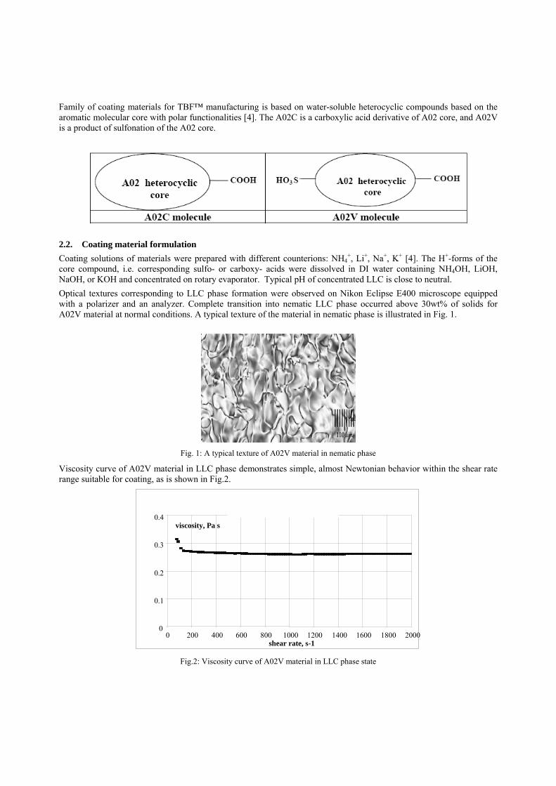
Family of coating materials for TBF™ manufacturing is based on water-soluble heterocyclic compounds based on the aromatic molecular core with polar functionalities [4]. The A02C is a carboxylic acid derivative of A02 core, and A02V is a product of sulfonation of the A02 core.
2.2. Coating material formulation Coating solutions of materials were prepared with different counterions: NH4
+, Li+, Na+, K+ [4]. The H+-forms of the core compound, i.e. corresponding sulfo- or carboxy- acids were dissolved in DI water containing NH4OH, LiOH, NaOH, or KOH and concentrated on rotary evaporator. Typical pH of concentrated LLC is close to neutral. Optical textures corresponding to LLC phase formation were observed on Nikon Eclipse E400 microscope equipped with a polarizer and an analyzer. Complete transition into nematic LLC phase occurred above 30wt% of solids for A02V material at normal conditions. A typical texture of the material in nematic phase is illustrated in Fig. 1.
Fig. 1: A typical texture of A02V material in nematic phase
Viscosity curve of A02V material in LLC phase demonstrates simple, almost Newtonian behavior within the shear rate range suitable for coating, as is shown in Fig.2.
0
0.1
0.2
0.3
0.4
0 200 400 600 800 1000 1200 1400 1600 1800 2000 shear rate, s-1
viscosity, Pa s
Fig.2: Viscosity curve of A02V material in LLC phase state

2.3. Retarder production We have produced retardation films by coating the developed materials in the LLC phase on glass or plastic substrates. Coating was performed using micro-grooved rod with the groove profile controlling the required thickness of the wet film. A uniform wet coating of 5 to 15micron thick allows producing TBF™s from 100 to 1100 nm thick depending on concentration of the initial material. During the coating, LLC material is subjected to the strong shear force when squeezed through the micro-grooves. Shear field imposes flow alignment on the supramolecular structures of the LLC material. The necessary alignment can be achieved under high shear rates (~ 10-6 s-1).
2.4. Optical characterization To verify that materials are useful in LCD optical applications one has to make sure that material solutions are colorless, in other words they have extinction coefficients on the order of 10-3 in visible spectral range. A typical absorbance spectrum of a diluted solution is presented in Fig.3.
Fig.3: Absorbance spectra of A02V water solution with concentration C~5x10⁻⁴M
To determine all three refractive indices we used combined measuring and calculation technique. First, the values of one of the refraction indices and thickness of the anisotropic film were determined from spectral measurements using Varian Cary-500 spectrophotometer (400-750 nm spectra of transmittance at normal incidence and reflectance for 12 degree incidence) and the obtained data were processed by the Multilayer software specially designed for inverse problem solving, producing nx spectra and thickness h as the output data. Second, in-plane (R0) and out-of-plane (Rth) retardance spectra are measured by means of Axometrics Mueller Matrix Polarimeter (Fig. 4) in the range of 400 – 750 nm. To record out-of-plane retardance spectra, the sample was rotated about both fast axis x (coating direction) and slow axis y. Finally, nx, ny and nz spectra were calculated by a special algorithm using obtained nx , h, R0 and Rth values as input data.

Fig.4: General scheme of Axometrics Spectropolarimeter used in MMP technique for out-of-plane indexes determination.
5. RESULTS AND DISCUSSION
5.1. Molecular arrangement and refraction indices TBF™ retarders are new optical elements. TBF retarders are produced from aqueous Lyotropic Liquid Crystal phase of column-like supramolecules formed by plate-like conjugated molecules stacked in plate-to-plate fashion. Molecular order of supramolecules dictates position of molecular elements relative to the surface of the substrate. Each molecule forms ππ− interaction with its two neighbors in the rod-like supramolecule, which is the kinetic element of the liquid system. These kinetic elements are large enough to be influenced by hydrodynamic flow of the liquid phase during coating process. Hydrodynamic flow creates global order in the supramolecular LLC during coating process and passes this order to solid state film, which is the resulting phase of the drying process. In solid state film supramolecules are aligned along the coating direction, which makes molecular elements of a supramolecule positioned with their plane perpendicular to the coating axis. The most important feature of the new materials is the large difference in refraction coefficients for the different optical axis. Molecular nature of a material allows step-by-step engineering of optical performance and production of variety of combinations of refraction coefficients yielding retardation plates of different types. Refractive indices of A02V material coated on glass are presented in Fig.5. It can be seen that in-plane birefringence reaches 0.35 in this case and the film obtained is close to negative A-plate retarder (for coated TBF™ layer thickness h=890nm: delta nxy = –0.328 (
328.0−=Δ ΥΧn ( nm650=λ ); 352.0−=Δ ΥΧn ( nm550=λ ); 404.0−=Δ ΥΧn ( nm450=λ )).

As can be seen, the lowest value of refraction coefficient is along coating direction while the planes of polyaromatic cores forming supramolecules are perpendicular to the substrate plane with the long supramolecular axes aligned along the coating direction (see Fig.6). If we assume that conjugation is the reason for high polarizability of molecular elements then it appears that ππ− interaction between flat core molecules can not produce stronger conjugation than conjugation in the plane of molecule.
1.4
1.5
1.6
1.7
1.8
1.9
2
2.1
400 450 500 550 600 650 700 750wavelength, nm
n_xn_yn_z
Fig. 5: TBF™ A02V negative A-plate (close to uniaxial) retarder coated from LLC on glass: refractive indices as determined by
MMP technique
Fig. 6: A02V packing to form close to uniaxial negative A-plate

Coating of A02C solution allows producing positive C-plate. Unlike the above-described arrangement, we now deal with random in-plane orientations of supramolecular axes, while the planes of polyaromatic cores still remain orthogonal to the substrate plane (Fig. 7). The refraction indices spectra for this retardation plate are shown in Fig. 8.
Fig. 7: A02C packing to form close to uniaxial positive C-plate
1.4
1.5
1.6
1.7
1.8
1.9
2
2.1
400 450 500 550 600 650 700 750wavelength, nm
n_xn_yn_z
Fig. 8: TBF™ A02C positive C-plate (uniaxial) retarder coated from LLC on glass: refractive indices as determined by MMP
technique
5.2. TBF™ application for LCD optical compensation

Viewing angle related issues in LCDs (contrast loss, grey scale inversion, color shifts for both saturated and gray scale colors) are known to be due to the light leakage via crossed polarizers under oblique incidence as well as the intrinsic retardation of the Liquid Crystal cell itself. Viewing angle characteristics for Vertical Alignment (VA) LCD [4] mode can be improved by use of TBF™ optical compensators with negative birefringence.
As can be seen from the example below (Fig. 9), TBF™ materials coated on TAC substrates represent advanced compensators for LCD.
Fig. 9: Comparison of non-compensated and TBF™-on-TAC compensated VA LCD design performance: Contrast ratio viewing
angle dependence at 550nm (results calculated using TBF™ A02V characteristics)
Supramolecular LLC provides excellent venue for pre-ordering material in the liquid phase for production of ordered molecular films. Supramolecular LLC is the coating material of choice for printing process in retarder manufacturing because it is aqueous and with variable concentration of solids which provides controllable viscosity. It is well known that printing provides inexpensive manufacturing process and application of printing to manufacturing of retarders promises future cost reduction for LCD Home TV. The data above show that new retarders can be successfully deployed for compensation of LC cells and polarizers.
6. CONCLUSIONS
We developed new coatable materials and method of manufacturing for thin birefringent (negative A-plate and positive C- plate type) films with optical anisotropy of about 0.3. Birefringent layers are tested for LCD optics compensation. We demonstrated compensation of VA mode LCD with a single layer of birefringent coatable material with negative A-plate properties coated on commercially available TAC substrates. The demonstration proves the new optical film design for VA compensation that provides a LCD optical stack cost reduction and enhancement of optical performance.

The new family of chemical compounds is developed and well suited for the fabrication of optical compensators for LCD Home TV.
ACKNOWLEDGMENTS
Authors are grateful Dr. I. Kasianova for refraction indices measurements and Dr. E. Neburchilova for help in the paper preparation.
REFERENCES
1. V.G. Chigrinov, H.S. Kwok, W.C. Yip, V.M. Kozenkov, E.K. Prudnikova, B. Tang, F. Salhi, "New Photo-Aligning and Photo-Patterning Technology: superthin internal polarizers, retarders and aligning layers", Proceedings of SPIE, 4463, pp. 117-131, 2001.
2. H. Mori and P. Bos, “Designing Concepts of the Discotic Negative Birefringence Compensation Films”, SID’98 DIGEST, Anaheim, California, May 1998, Vol. XXIX, pp. 830-833.
3. S.-H. Ahn, A.B. Davey, W.A. Crossland, “Optical Performance of Compensated Normally Black and Normally White TN Modulated PLLCDs”, SID’01 DIGEST, San Jose, California, June 2001, Vol. XXXII, pp. 842-845.
4. Patents pending.
Copyright © 2022 FDOKUMEN