
Thermal plasmas in material processing
14
Bull. Mater. Sci., Vol. 18, No. 6, October 1995, pp. 741 754. ~ Printed in India. Thermal plasmas in material processing N VENKATRAMANI Laser and Plasma Technology Division, Bhabha Atomic Research Centre, Bombay400 085, India Abstract. Thermal plasmas are partially ionized gases at atmospheric pressures,characteri- zed by temperatures in the range of 2000-20,000 K and charged particle number densities in the range of 1019 1021 perm 3. Thermal plasmas are produced by plasma torches as a highly constricted jet. The high temperatures, enthalpies and heat fluxes in the plasma jet make it amenable to many chemical and metallurgical processes of industrial importance. The processingenvironmentcan be inert as in the ~:ase of argon or nitrogen plasmasor can be made reactive by introducing suitable gases. Reactive thermal plasma processing is a novel technique, wherein the plasma enters the reaction scheme, with ions and excited species opening up new channels. This technique is versatilein producing a wide variety of materials like oxides, carbides, borides, aluminides and coatings of diamond, superconductors and bioceramics. In this paper, the basic design of the plasma devicesand some of the significant materials-related activitiescarried out recently at BARC are reported. Keywords. Thermalplasma; plasma devices;material processing;plasma spraying. 1. Introduction Plasma technology has in recent years emerged as a novel technique for the manufac- ture of newer and better materials (Dembovsky 1985; Feinmann 1987; Pfender 1988; Knight et al 1991). The high temperature together with the high reactivity due to the presence of free ions and radicals makes the plasma a powerful medium to promote chemical reactions. Plasmas of technological interest can be broadly divided into two categories: thermal plasmas and the non equilibrium plasmas. Thermal plasmas are atmospheric pressure plasmas characterized by high enthalpy content and tempera- tures around 2000-20,000 degrees. Non equilibrium plasmas are low pressure plasmas characterized by high electron temperatures and low ion and neutral temperatures. The use of nonequilibrium plasmas (or more commonly known as the glow discharge plasmas) in lighting, surface cleaning, etching, film deposition, etc has been fairly well established. The use of thermal plasmas in cutting, welding and spraying has also been known over three decades. However, it is only recently that the use of thermal plasmas in materials technology is emerging as a topic of active interest in the fields of metallurgy, chemical engineering, and other areas of material processing. A plasma beam more commonly known as a plasma jet is obtained from a plasma torch (also known as a plasmatron). The plasma jet produces an effluent over a wide range of composition and operating conditions, which can be closely controlled. The high temperatures, enthalpies and heat fluxes obtained in the plasma jet are far higher than any other known technique and has widespread application in material testing and material processing. Plasma torches used in material processing applications, are energized by direct current, alternating current at mains frequency, or at radio frequency. Conventional plasma torches employ argon or nitrogen as plasma gases. With the use of additives like hydrogen, hydrocarbons or oxygen, the plasma gas enters the reaction scheme, with the ions and excited species opening up new channels. The 741
-
Upload
khangminh22 -
Category
Documents
-
view
0 -
download
0
Transcript of Thermal plasmas in material processing

Bull. Mater. Sci., Vol. 18, No. 6, October 1995, pp. 741 754. ~ Printed in India.
Thermal plasmas in material processing
N V E N K A T R A M A N I Laser and Plasma Technology Division, Bhabha Atomic Research Centre, Bombay 400 085, India
Abstract. Thermal plasmas are partially ionized gases at atmospheric pressures, characteri- zed by temperatures in the range of 2000-20,000 K and charged particle number densities in the range of 1019 1021 perm 3. Thermal plasmas are produced by plasma torches as a highly constricted jet. The high temperatures, enthalpies and heat fluxes in the plasma jet make it amenable to many chemical and metallurgical processes of industrial importance. The processing environment can be inert as in the ~:ase of argon or nitrogen plasmas or can be made reactive by introducing suitable gases. Reactive thermal plasma processing is a novel technique, wherein the plasma enters the reaction scheme, with ions and excited species opening up new channels. This technique is versatile in producing a wide variety of materials like oxides, carbides, borides, aluminides and coatings of diamond, superconductors and bioceramics. In this paper, the basic design of the plasma devices and some of the significant materials-related activities carried out recently at BARC are reported.
Keywords. Thermal plasma; plasma devices; material processing; plasma spraying.
1. Introduction
Plasma technology has in recent years emerged as a novel technique for the manufac- ture of newer and better materials (Dembovsky 1985; Feinmann 1987; Pfender 1988; Knight et al 1991). The high temperature together with the high reactivity due to the presence of free ions and radicals makes the plasma a powerful medium to promote chemical reactions. Plasmas of technological interest can be broadly divided into two categories: thermal plasmas and the non equilibrium plasmas. Thermal plasmas are atmospheric pressure plasmas characterized by high enthalpy content and tempera- tures around 2000-20,000 degrees. Non equilibrium plasmas are low pressure plasmas characterized by high electron temperatures and low ion and neutral temperatures. The use of nonequilibrium plasmas (or more commonly known as the glow discharge plasmas) in lighting, surface cleaning, etching, film deposition, etc has been fairly well established. The use of thermal plasmas in cutting, welding and spraying has also been known over three decades. However, it is only recently that the use of thermal plasmas in materials technology is emerging as a topic of active interest in the fields of metallurgy, chemical engineering, and other areas of material processing.
A plasma beam more commonly known as a plasma jet is obtained from a plasma torch (also known as a plasmatron). The plasma jet produces an effluent over a wide range of composition and operating conditions, which can be closely controlled. The high temperatures, enthalpies and heat fluxes obtained in the plasma jet are far higher than any other known technique and has widespread application in material testing and material processing. Plasma torches used in material processing applications, are energized by direct current, alternating current at mains frequency, or at radio frequency.
Conventional plasma torches employ argon or nitrogen as plasma gases. With the use of additives like hydrogen, hydrocarbons or oxygen, the plasma gas enters the reaction scheme, with the ions and excited species opening up new channels. The
741

742 N Venkatramani
Figure i. Schematic of plasma material processing facility./1. DC power source; 2. HF unit; 3. control console: 4. powder feeder: 5. plasma torch; 6. reaction chamber; 7. collection chamber; 8. exhaust; 9. cabling: 10. gas supply: 11. cooling water supplyl.
versatility of the technique and its advantages favour the adoption of reactive plasma processing by designing dedicated systems to meet specific requirements. A compre- hensive program on thermal plasma device development, plasma diagnostics and material processing has been undertaken at BARC. This paper will focus on the basic design of plasma devices and some of the significant materials-related activities carried out recently.
2. Equipment description
The material processing thermal plasma facility consists of a plasma torch energized by a dc power source. An hf unit provides initial starting up of the discharge. The auxiliary facilities include plasma gases and cooling water for torch and chamber cooling. The material feed system and torch handling systems will help in the proper functioning of the facility (figure 1).
2.1 Plasma torch
Plasma torch is a device which produces a plasma beam in the form of an electric arc at atmospheric pressure. The plasma torch of conventional design consists of a tungsten rod cathode and a water cooled copper anode, shaped in the form of a nozzle (figure 2). The two electrodes are separated by an insulator which also has an inlet for plasma gas. When a gas is introduced in the electrode gap and a dc arc is established between the electrodes, the arc is pushed through the nozzle resulting in a high temperature, high velocity flame. Electromagnetic forces and gas stabilization constrict the arc column and heat the plasma to nearly 20,000 degrees. The body of the torch consists of cooling chambers for cathode and anode. The torch is supplied with water and power through water cooled cables which are in turn coupled to main' power supply and water heaters.

Thermal plasmas in material processing 743
Figure 2. Cross section of a d c plasma torch.
©
i m
@
® [ 1
Figure 3. Plasma torch in transferred (A) and nontransferred (B) arc mode of operation. (1. Cathode; 2. gas flow: 3. anode: 4. cooling channel; 5. plasma jet: 6. substrate).
The arc is a highly turbulent discharge phenomenon with considerable fluctuations of voltage and current (Venkatramani et al 1989). Any disturbance from equilibrium is undesirable as it will tend to extinguish the arc. The arc needs a stabilizing mechanism which constricts the arc column to enable the steady passage of the electric current. There are basically three techniques to stabilize the plasma torch: through gas flow, cold wall and through magnetic fields. Gas flow stabilization is the simplest and the most common technique. In this technique, a flowing external cold layer of a gas surrounds the arc column and constricts it. The flow stabilization can be vortex or axial depending on the mode of injection. In the former case, the vortex flow creates centrifugal forces, which drive the cold gas towards the walls of the chamber. Plasma torches used for

744 N Venkatramani
Table 1. Arc voltages in transferred and nontransferred arc devices.
Transferred arc mode Nontransferred arc mode Gas (e.g. cutting) (spraying)
Argon 110-300 25-50 Nitrogen 150-400 60 100 Argon/hydrogen 130-350 80-100 Nitrogen/hydrogen 150-400 90-150
cutting or spraying applications are normally vortex stabilized. The arc lengths are short but the arc itself is more intense. The axial flow stabilized arcs have a laminar flow and the cold gas tends to surround the hot core.and consequently the arcs are longer. They are used for metal processing applications. Double stabilization can be achieved by twin flow torches having two coaxial flows, one as plasma forming gas and the other as shield gas. There are several versions of the torch based on differences in the stabilization of the arc, electrode geometry, plasma gas, electrode cooling medium and the type of gas flow. The plasma jet can be operated in a transferred or nontransferred arc mode depending on whether the arc is electrically transferred to the work piece or not (figure 3). Typical voltages in a transferred and nontransferred devices are given in table 1. In the transferred arc devices, the arc normally passes from the cathode through the nozzle orifice to the anode/ground as it represents the path of least resistance.
2.2 Materials for cathode and anode
Since the plasma torch needs an incandescent thermionic cathode, high melting point metals or alloys are used. Thoriated tungsten cathodes are used due to their superior electron emission characteristics. They are quite stable for operation up to current densities 10-20 A/mm z. In torches with low power outputs, the electrode tip is cone shaped and is truncated for high outputs. For air operated torches hafnium or zirconium electrodes are used. The electric arc is stabilized by using a constricted anode nozzle and by the resultant aerodynamic effects in the streaming plasma gas. The heat generated at the anode is quite large in plasma torches. However, for long service life, it is desirable to restrict it to about 120 W/mm z. The obvious choice of the material for anode is copper due to its high thermal conductivity.
2.3 Plasma gas
The plasma gas flow rate and the electric power to the plasma torch must be properly balanced in order to get a stable arc. Gas flow must be carefully metered as the current is built up in the arc stream, so as not to blow out the arc nor fail to cause the necessary thermal pinch effect to force the arc down through the nozzle. Improper sequencing can cause catastrophic failure of the electrodes. The most commonly used gases in the generation of plasma are argon, helium, nitrogen, air and hydrogen. If an inert atmosphere is desired, argon is normally used, which has to be extremely pure. Reactive gases can be used to impart reducing, oxidizing, chloriding or nitriding effects to the plasma.

Thermal plasmas in material processing
Table 2. Ratings of plasma devices.
745
Power level in kW Device applications
0-1 1
1-10 10-100 100-1000
>1000
Welding of foils: bellows Welding thin sheets; cutting thin plates Plasma cutting; welding; spraying; machining; material processing Under water cutting; plasma processing; plasma metallurgy: space simulation High enthalpy source; wind tunnels; plasma heaters
3. Applications of thermal plasmas
Plasma processing, other than plasma cutting, welding and spraying, which until recently was confined to the realms of laboratory experiments is being increasingly utilized in many chemical syntheses and metallurgical operations of importance. The very high temperature and high thermal power density obtainable from plasma torches not only help in augmenting conventional processing techniques, but also offer new approaches to realize a variety of chemical reactions (Fauchais et al 1983). Plasma processing is particularly attractive in producing extra pure metals and alloys of precisely controlled compositions required in nuclear and other advanced technolo- gies. It is also used in the preparation of fine powders of engineering ceramics. Plasma reactor can also be efficiently utilized in refining metals or for processing low grade ores. Of particular interest in the context of our nuclear energy programme are the preparation of zirconium-based metals and alloys, carbides and borides of selected metals.
Thermal plasma devices operate over a wide range of power levels: from a few tens of Watts to a few MW (table 2). The lower power ranges are used for industrial operations like welding, cutting and spray applications. The medium power devices in the range of hundreds of kW are used for plasma processing and metallurgical applications. The high power devices in the range of several MW are used in space and defence oriented applications; but the plasma metallurgy also employs devices in this power range. A review of the currently available state-of-art thermal plasma devices is given by Camacho (1988) and Knight et al (1991).
4. Plasma spraying
Plasma cutting, welding and spray torches have been in operation as a specialized machine in industrial environment. Plasma cutting torches are currently being ex- ploited in handling stainless steels, nonferrous materials, high temperature alloys etc. Plasma arc welding (PAW) is a more updated version of TIG welding process. Plasma spray technology is one of the most widely used techniques to prepare composite structural parts with improved surface properties and increased life span (Zaat 1983; Nicoll et al 1986). The structural components in modern high technology fields-- nuclear, space, power, oil exploration etc--operate in extremely hostile environment of temperature, gas flow, pressure and corrosive media. In many of these applications, properties desired at the surface are different from those at the bulk of the components. The present trend is to employ a composite structure in such cases, viz. a core material

746 N Venkatramani
along with a strongly bonded surface layer, each one meeting a specific requirement. Plasma deposition is a continuous process and can be used to spray coat ceramics, metals, alloys and compounds.
Plasma spray process uses a nontransferred arc plasma torch. The powder to be coated is introduced into the plasma jet streaming out of the nozzle, where it gets melted and the molten droplets are sprayed on to the substrate at high velocities. In plasma spraying, the quality of coating is affected by many variables which are interrelated. These variables include primarily those of the plasma, powder, powder feed, substrate and spray procedure (Sreekumar 1991). Plasma spray can be done onto any substrate. Plasma spraying has a wide variety of industrial applications in the preparation of wear resistant, thermal barrier and protective coatings. There are also other limited applications like preparation of near net shapes, free standing structures, special purpose and decorative coatings. Significant achievements at BARC include the development of YBCO superconducting coatings (Karthikeyan et al 1989), stabilized zirconia-alumina composite coatings (Ananthapadmanabhan et al 1991) and hydroxy apatite coatings for medical applications.
Plasma spray technology, since its discovery in 1957 has been exclusively done in air with shield gases. This is known as the atmospheric or air plasma spraying (APS). Plasma spraying in normal ambient conditions is suitable for oxides. However one of the major problems with the plasma spraying of metals, alloys and intermetallics is plasma effluent powder mixture coming into contact with the atmospheric oxygen (Ananthapad- manabhan et al 1993). This results in coating contaminations and new developments are taking place to minimize these contaminations. At BARC a controlled environment/ vacuum plasma spray equipment has been designed and is under fabrication.
4.1 Deposition of diamond films
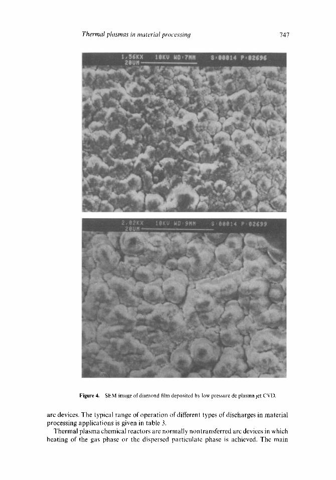
Diamond and diamond-like carbon (DLC) films have been grown on substrates at very high deposition rates using low pressure plasma torches (Kurihara et al t989). A low pressure plasma jet process for diamond growth has been developed using a mixture of methane and hydrogen along with argon as the plasma gas (Ramachandran et a11995). The films have been characterized by XRD, Raman and SEM. Figure 4 shows the SEM image of the film.
4.2 Twin wire arc spray
Electric arc spraying is a process of thermal spray coating in which instead of powders, two wires are melted by an electric arc and the fused particles are projected onto a surface to build up an adherent coating. The two wires may be of the same material or dissimilar materials (pseudo alloy coatings). The carrier gas, which is used to project the molten particles can be compressed air or inert gas. It is also possible to use cored wires to prepare composite coatings (e.g.) carbides in metal matrix. The schematic of the electric arc metallizing system developed at BARC is given in figure 5 (Chakravarthy et al 1993).
5. Plasma material processing
Plasma chemical processing can be carried out in glow (including abnormal glow) and
Thermal plasmas in material processinq 747
Figure 4. SEM image of diamond film deposited by low pressure dc plasma jet CVD.
arc devices. The typical range of operation of different types of discharges in material processing applications is given in table 3.
Thermal plasma chemical reactors are normally nontransferred arc devices in which heating of the gas phase or the dispersed particulate phase is achieved. The main

748 N Venkatramani
Figure 5. Schematic diagram of twin wire arc spray system. (1. Motorized arc spray gun; 2. dc power supply (20-30V, 0-400A); 3. wire reel holder; 4. gas cylinder; 5. air compressor; 6. control and display.
Table 3. Typical operating regimes of plasma reactors.
Power Gas pressure Temperature Flow rate Discharge (kW) (atm.) (K) (mg/s)
Glow < 5 <0-1 < 1000 < 5 Arc 1 - 1000 0" 1-10 3000- 30000 > 50
components of the plasma chemical reactor system are the input feeding system, the plasma generator with the associated power supplies, a mixer-reactor unit and a quenching system (figure 1). The mixing can also be achieved by premixing the reactants in the input feed system to the generator especially with gases. However, it is not a preferred choice, since the electrodes are subjected to corrosion. The role of the quenching system is to freeze the products at the high temperature equilibrium level. It can be achieved by cold gas injection, cold-wall quenching, fluidized bed, adiabatic expansion, or by impinging into a liquid spray/bath.
5.1 Production of zirconia from zircon
Plasma decomposition offers itself as an excellent technique for decomposing minerals or raw materials. The decomposition of zirconium silicate (zircon sand) into zirconium dioxide and silica has been demonstrated. Silica has been extracted by leaching with alkali or acid leaving zirconia. ZrSiO4 is thermodynamically unstable above 1676°C, when it starts to decompose into zirconia and silica. The reverse reaction can be prevented by rapid cooling.
ZrSiO4 --* Z r O 2 + S i O 2 ( T > 1676°C).
The structure of plasma dissociated zirconia is mainly monoclinic. The completely molten particles generally undercool to about 0.8 T m, where Tm is the melting point, before crystallization is nucleated because there are no nucleating sites. An extensive parametric study has been carried out by Ananthapadmanabhan et a! (1994) using a 50 kW prototype dc plasma reactor for producing zirconia. The study indicates that

Thermal plasmas in material processing 749
the percentage dissociation is strongly dependent on the power input to the torch (figure 6).
5.2 Plasma synthesis and preparation of fine powders
The use of thermal plasmas in the vapour phase chemical synthesis of carbides, nitrides, borides and oxides is extremely interesting due to the high temperatures involved, the flexibility in the choice of reactants and the rapid cooling which is possible. The plasma process is usually a single step process which can help in the preparation of pure, ultra fine particles. The starting material is introduced in the form of a gas, solid, liquid or in combination. Submicron aluminium nitride, silicon carbide and titanium boride powders can be produced with dc/rf plasma techniques in a cost effective manner (Becker et al 1987).
5.2a Titanium and tungsten carbide: Titanium and tungsten carbides have been synthesized in a thermal plasma reactor from the respective metal powders and acetylene. The chemical reaction leading to the formation of carbides can be represen- ted by the following equations
T i + 0 " 5 C 2 H 2 ~ T i C + 0 - 5 H 2 AGO=-68.8Kcal ,
W + 0 . 5 C 2 H 2 - - ~ W C W 0 . 5 H 2 AGO= -33.5Kcal.
The standard free energy changes accompanying the above reactions can be calculated for various temperatures from the available data and it is seen that it is negative over wide temperature ranges indicating that the reactions are favourable. Recent results of the experiments carried out at BARC showed that at 12 kW plasma power, the amount of TiC formed depends strongly on the C 2 Ha flowrate (table 4).
e- o o o ° ~ .i.a
._o O O
w
k5 o tlO
.9 i -
g 13_
/ / a (o i2
Power Input (kW)
Figure 6. Dependence of zircon dissociation on torch power input.
Table 4. Dependence of TiC formation on the flowrate of C2 H2.
Flowrate of C 2 H 2 (LPM) Wt. % of TiC formed at 12kW
0"3 50 0"6 63 1"0 67 2"0 78

750 N Venkatramani
X-ray diffraction pattern and SEM of a typical plasma synthesized titanium carbide are shown in figures 7 and 8 respectively. With a 8% concentration of the reactive gas the conversion rate was around 80%. Further optimization is necessary, with respect to torch power, precursor flowrates and point of entry of the reactants to increase the conversion rate.
5.2b Nickel aluminide: Nickel aluminide and its derivatives have excellent high temperature mechanical properties and oxidation resistance, which makes them useful as a bond coat material in thermal spray applications. Nickel aluminide was syn- thesized in a plasma torch operating in a nontransferred arc mode using premixed powders with excess aluminium as precursor material with argon as carrier gas and argon and nitrogen as plasma gas. The X-ray diffraction patterns of the coated substrates showed a single homogeneous phase ofNi 3 A1. The spherical morphology of the plasma synthesized nickel aluminide is evident from figure 9. Since, the residence times of particles in a plasma torch are small, of the order of few milliseconds, intimate mixing of reactant powders is essential. The formation of Ni 3 A1 is highly exothermic, hence, once the reaction is initiated, it goes to completion. The thermal plasma technique is extremely simple and is expected to be cost effective.
5.2c Aerosol generation: Aerosol contributes a significant fraction to industrial pollution. Study of aerosol generation and transport is an important aspect of pollution control and monitoring. A dc plasma torch based system has been developed
Z ta I-. Z
I1!
,01 ";'~C Zoo
.f i Io&
1o • 'o +'o 2. 0 ~E~,~IP. i . .5
Figure 7. XRD pattern of reactively sprayed TiC deposits.

Thermal plasmas in material processin,q 751
Figure 8. Typical SEM of reactively sprayed TiC deposits.
and is in operation. Aluminium and iron powders of 20-40 # size were introduced into the plasma torch and submicron size particles have been generated and studied (figure 10).
5.3 Plasma metallurgy
Plasma furnaces have a high melting efficiency, and are capable of producing alloys with low carbon, low hydrogen and low oxygen content. The transferred arc plasma

752 N Venkatramani
Figure 9. SEM image of plasma processed Ni aAI.
devices used in metallurgical industry are characterized by high energy concentratiom high thermal efficiency, excellent heat and mass transfer conditions, and adequate residence time. In these plasma furnaces, the arc is transferred to the molten pool in the crucible or in the form of a falling film. A 150 kW plasma melting torch has been developed and extensive experiments have been carried out for characterizing the torch performance.
5.3a Nuclear waste consolidation and treatment: The consolidation and disposal of nuclear waste poses one of the challenging tasks in the nuclear industry. A plasma

Thermal plasmas in material proc essin,q 753
E
E
E
g3
o E " 4 ' ' [--]]0
Diameter ( Dae, microns)
Figure 10. Size distribution of aluminium aerosols generated in a plasma torch.
melter has been developed at BARC where zirconium scrap can be melted and consolidated into ingots. The plasma melter rated at 50 kW operates with a cold copper hearth. The molten pool is the anode and the arc is transferred from the torch to the molten pool. A plasma centrifugal furnace has been developed by Retech Inc. (Sears et al 1990) to stabilize solid toxic and nuclear waste material. The furnace employs a thermal plasma torch to melt and vitrify the waste components.
6. Conclusion
The use of plasma torches at large power levels in the industrial field has been increasing• Recent work on a variety of applications carried out at BARC and of interest to material scientists has been reviewed in this paper. Plasma reactors are suitable for treating gaseous and particulate reactants due to the high temperatures and high heat transfer rates. The introduction of particles in the plasma reactors poses a few problems as compared to gaseous reactants• The major difficulty is the short residence time of the particles in the plasma environment, normally of the order of several milliseconds. This residence time is adequate for processes involving physical changes like melting and hence operations like plasma spraying can be done quite conveniently• Even for processes involving thermal dissociation, this technique can be employed. However, when there are reactions involving reaction between gaseous and condensed phases, or diffusion across the condensed phase, the technique may prove to be not fully adequate• So the overall objective of the reactor design is to make the particles pass through the hottest zone for the longest duration of time. On the other hand, reactions • . /
revolving gaseous reactants which on cooling give rise to finely dispersed particles can be conveniently achieved in plasma chemical reactors.
Acknowledgements
The author is grateful to Dr B A Dasannacharya, Director, MDTG and Shri U K Chat- terjee, Head L and PTD, BARC for their encouragement and support. He would also like to thank his colleagues Dr P V Ananthapadmanabhan, Dr A K Das, Shri P S S Murthy, Dr D S Patti and Shri K P Sreekumar for useful discussions and information on the unpublished work.

754 N Venka t ramani
References
Ananthapadmanabhan P V, Sreekumar K P, Venkatramani N and Muraleedharan K V 1991 Surf Coat. Technol. ,19 62
Ananthapadmanabhan P V, Sreekumar K P, Ravindran P V and Venkatramani N 1993 Thin Solid Films 224 148
Ananthapadmanabhan P V, Sreekumar K P, Veeramani Iyer K and Venkatramani N 1994 Mater. Chem. Phys. 38 15
Becker A J, Meyer T N, Smith F N and Edd J F 1987 MRS Syrup. Proc. 98 335 Camacho S L 1988 Pure & Appl. Chem. 60 619 Chakravarthy D P, Madanmohan M S, Barve D N and Venkatramani N 1993 BARC Report
BARC/1993/E/032, Bombay Dembovsky V 1985 Plasma metaUuroy--The principles (Amsterdam: Elsevier) Fauchais P, Bourdin E, Coudert J F and McPherson R 1983 Topics Curr. Chem. 107 59 Feinmann J 1987 Plasma technolooy in metallurgical industry (Warrendale: Iron & Steel Society) Karthikeyan J, Sreekumar K P, Venkatramani N, Kurup M B, Patil D S and Rohatgi V K 1989 Appl. Phys.
A: Solids and Surfaces 49 489 Knight R, Smith R W and Apelian D 1991 Int. Mater. Rev. 36 221 Nicoll A R, Gruner H, Wuest G and Keller S 1986 Mater. Sci. Technol. 2 214 Pfender E 1988 Pure & Appl. Chem. 60 591 Ramachandran K, Patil D S, Venkatramani N, Biswas A R, Venkateswaran S and D'Cunha R 1995 Proc. int.
conf on vacuum science and technolooy (INCO VAST-95), lndore Sears J W, Eschenbach R C and Hill R A 1990 Waste Management 10 165 Sreekumar K P, Karthikeyan J, Ananthapadmanabhan P V, Venkatramani N and Chatterjee U K 1991
BARC Report 1551, Bombay Venkatramani N, Chakravarthy D P, Barve D N and Rohatgi V K 1989 8th Int. Conf. on Plasma Physics,
New Delhi Zaat J H 1983 Ann. Rev. Mater. Sci. 13 9