Thermal Analysis of Engine Cylinder Fin by Varying Its Geometry and Material
8
IOSR Journal of Mechanical and Civil Engineering (IOSR-JMCE) e-ISSN: 2278-1684,p-ISSN: 2320-334X, Volume 11, Issue 6 Ver. I (Nov- Dec. 2014), PP 37-44 www.iosrjournals.org www.iosrjournals.org 37 | Page Thermal Analysis of Engine Cylinder Fin by Varying Its Geometry and Material P. Sai Chaitanya 1 , B. Suneela Rani 2 , K. Vijaya Kumar 3 1 GMR Institute of Engineering and Technology, GMR Nagar, Rajam 2 Aditya Institute of Technology and Managment, Tekkali 3 Bharat Institute of Engineering and Technology, Ibrahimpatnam, R.R. District Abstract: The Engine cylinder is one of the major automobile components, which is subjected to high temperature variations and thermal stresses. In order to cool the cylinder, fins are provided on the surface of the cylinder to increase the rate of heat transfer. By doing thermal analysis on the engine cylinder fins, it is helpful to know the heat dissipation inside the cylinder. We know that, by increasing the surface area we can increase the heat dissipation rate, so designing such a large complex engine is very difficult. The main aim of the present paper is to analyze the thermal properties by varying geometry, material and thickness of cylinder fins using ansys work bench. Transient thermal analysis determines temperatures and other thermal quantities that vary over time. The variation of temperature distribution over time is of interest in many applications such as in cooling. The accurate thermal simulation could permit critical design parameters to be identified for improved life. Presently Material used for manufacturing cylinder fin body is Aluminum Alloy A204 which has thermal conductivity of 110-150W/mk. Presently analysis is carried out for cylinder fins using this material and also using Aluminum alloy 6061 which have higher thermal conductivities. Key words: Dissipation, Thermal conductivity, Transient. I. Introduction: We know that in case of Internal Combustion engines, combustion of air and fuel takes place inside the engine cylinder and hot gases are generated. The temperature of gases will be around 2300-2500°C. This is a very high temperature and may result into burning of oil film between the moving parts and may result it seizing or welding of same. So, this temperature must be reduced to about 150-200°C at which the engine will work most efficiently. Too much cooling is also not desirable since it reduces the thermal efficiency. So, the object of cooling system is to keep the engine running at its most efficient operating temperature. It is to be noted that the engine is quite inefficient when it is cold and hence the cooling system is designed in such a way that it prevents cooling when the engine is warming up and till it attains to maximum efficient operating temperature, then it starts cooling. To avoid overheating, and the consequent ill effects, the heat transferred to an engine component (after a certain level) must be removed as quickly as possible and be conveyed to the atmosphere. It will be proper to say the cooling system as a temperature regulation system. It should be remembered that abstraction of heat from the working medium by way of cooling the engine components is a direct thermodynamic loss. Natural Air Cooling In normal cause, larger parts of an engine remain exposed to the atmospheric air. When the vehicles run, the air at certain relative velocity impinges upon the engine, and sweeps away its heat. The heat carried-away by the air is due to natural convection, therefore this method is known as natural air-cooling. Engines mounted on 2-wheelers are mostly cooled by natural air. As the heat dissipation is a function of frontal cross-sectional area of the engine, therefore there exists a need to enlarge this area. An engine with enlarge area will becomes bulky and in turn will also reduce the power by weight ratio. Hence, as an alternative arrangement, fins are constructed to enhance the frontal cross-sectional area of the engine. Fins (or ribs) are sharp projections provided on the surfaces of cylinder block and cylinder head. They increase the outer contact area between a cylinder and the air. Fins are, generally, casted integrally with the cylinder. They may also be mounted on the cylinder.
-
Upload
independent -
Category
Documents
-
view
0 -
download
0
Transcript of Thermal Analysis of Engine Cylinder Fin by Varying Its Geometry and Material
IOSR Journal of Mechanical and Civil Engineering (IOSR-JMCE)
e-ISSN: 2278-1684,p-ISSN: 2320-334X, Volume 11, Issue 6 Ver. I (Nov- Dec. 2014), PP 37-44 www.iosrjournals.org
www.iosrjournals.org 37 | Page
Thermal Analysis of Engine Cylinder Fin by Varying Its
Geometry and Material
P. Sai Chaitanya1, B. Suneela Rani
2, K. Vijaya Kumar
3
1GMR Institute of Engineering and Technology, GMR Nagar, Rajam 2Aditya Institute of Technology and Managment, Tekkali
3Bharat Institute of Engineering and Technology, Ibrahimpatnam, R.R. District
Abstract: The Engine cylinder is one of the major automobile components, which is subjected to high
temperature variations and thermal stresses. In order to cool the cylinder, fins are provided on the surface of the
cylinder to increase the rate of heat transfer. By doing thermal analysis on the engine cylinder fins, it is helpful to
know the heat dissipation inside the cylinder. We know that, by increasing the surface area we can increase the
heat dissipation rate, so designing such a large complex engine is very difficult. The main aim of the present
paper is to analyze the thermal properties by varying geometry, material and thickness of cylinder fins using
ansys work bench. Transient thermal analysis determines temperatures and other thermal quantities that vary
over time. The variation of temperature distribution over time is of interest in many applications such as in
cooling. The accurate thermal simulation could permit critical design parameters to be identified for improved
life. Presently Material used for manufacturing cylinder fin body is Aluminum Alloy A204 which has thermal conductivity of 110-150W/mk. Presently analysis is carried out for cylinder fins using this material and also
using Aluminum alloy 6061 which have higher thermal conductivities.
Key words: Dissipation, Thermal conductivity, Transient.
I. Introduction: We know that in case of Internal Combustion engines, combustion of air and fuel takes place inside
the engine cylinder and hot gases are generated. The temperature of gases will be around 2300-2500°C. This is
a very high temperature and may result into burning of oil film between the moving parts and may result it
seizing or welding of same. So, this temperature must be reduced to about 150-200°C at which the engine will
work most efficiently. Too much cooling is also not desirable since it reduces the thermal efficiency. So, the object of cooling system is to keep the engine running at its most efficient operating temperature. It is to be noted
that the engine is quite inefficient when it is cold and hence the cooling system is designed in such a way that it
prevents cooling when the engine is warming up and till it attains to maximum efficient operating temperature,
then it starts cooling.
To avoid overheating, and the consequent ill effects, the heat transferred to an engine component (after a
certain level) must be removed as quickly as possible and be conveyed to the atmosphere. It will be proper to say
the cooling system as a temperature regulation system. It should be remembered that abstraction of heat from the
working medium by way of cooling the engine components is a direct thermodynamic loss.
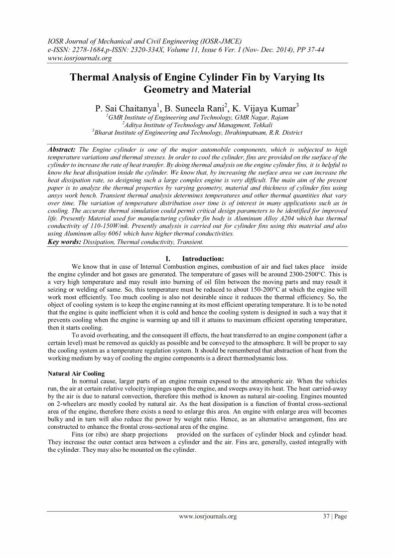
Natural Air Cooling In normal cause, larger parts of an engine remain exposed to the atmospheric air. When the vehicles
run, the air at certain relative velocity impinges upon the engine, and sweeps away its heat. The heat carried-away
by the air is due to natural convection, therefore this method is known as natural air-cooling. Engines mounted
on 2-wheelers are mostly cooled by natural air. As the heat dissipation is a function of frontal cross-sectional
area of the engine, therefore there exists a need to enlarge this area. An engine with enlarge area will becomes
bulky and in turn will also reduce the power by weight ratio. Hence, as an alternative arrangement, fins are
constructed to enhance the frontal cross-sectional area of the engine.
Fins (or ribs) are sharp projections provided on the surfaces of cylinder block and cylinder head.
They increase the outer contact area between a cylinder and the air. Fins are, generally, casted integrally with
the cylinder. They may also be mounted on the cylinder.
Thermal Analysis of Engine Cylinder Fin by Varying Its Geometry and Material
www.iosrjournals.org 38 | Page
Fig1. Natural air cooling
Fins:
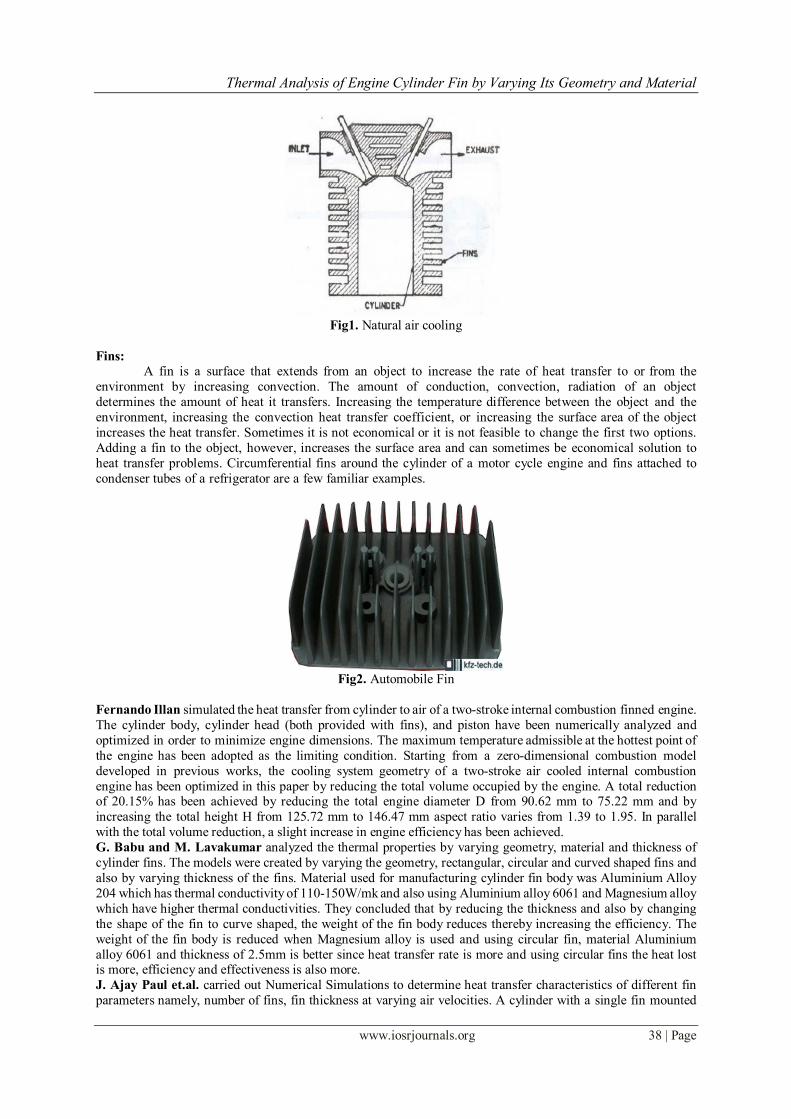
A fin is a surface that extends from an object to increase the rate of heat transfer to or from the
environment by increasing convection. The amount of conduction, convection, radiation of an object
determines the amount of heat it transfers. Increasing the temperature difference between the object and the
environment, increasing the convection heat transfer coefficient, or increasing the surface area of the object
increases the heat transfer. Sometimes it is not economical or it is not feasible to change the first two options.
Adding a fin to the object, however, increases the surface area and can sometimes be economical solution to
heat transfer problems. Circumferential fins around the cylinder of a motor cycle engine and fins attached to
condenser tubes of a refrigerator are a few familiar examples.
Fig2. Automobile Fin
Fernando Illan simulated the heat transfer from cylinder to air of a two-stroke internal combustion finned engine.
The cylinder body, cylinder head (both provided with fins), and piston have been numerically analyzed and
optimized in order to minimize engine dimensions. The maximum temperature admissible at the hottest point of
the engine has been adopted as the limiting condition. Starting from a zero-dimensional combustion model
developed in previous works, the cooling system geometry of a two-stroke air cooled internal combustion
engine has been optimized in this paper by reducing the total volume occupied by the engine. A total reduction of 20.15% has been achieved by reducing the total engine diameter D from 90.62 mm to 75.22 mm and by
increasing the total height H from 125.72 mm to 146.47 mm aspect ratio varies from 1.39 to 1.95. In parallel
with the total volume reduction, a slight increase in engine efficiency has been achieved.
G. Babu and M. Lavakumar analyzed the thermal properties by varying geometry, material and thickness of
cylinder fins. The models were created by varying the geometry, rectangular, circular and curved shaped fins and
also by varying thickness of the fins. Material used for manufacturing cylinder fin body was Aluminium Alloy
204 which has thermal conductivity of 110-150W/mk and also using Aluminium alloy 6061 and Magnesium alloy
which have higher thermal conductivities. They concluded that by reducing the thickness and also by changing
the shape of the fin to curve shaped, the weight of the fin body reduces thereby increasing the efficiency. The
weight of the fin body is reduced when Magnesium alloy is used and using circular fin, material Aluminium
alloy 6061 and thickness of 2.5mm is better since heat transfer rate is more and using circular fins the heat lost is more, efficiency and effectiveness is also more.
J. Ajay Paul et.al. carried out Numerical Simulations to determine heat transfer characteristics of different fin
parameters namely, number of fins, fin thickness at varying air velocities. A cylinder with a single fin mounted
Thermal Analysis of Engine Cylinder Fin by Varying Its Geometry and Material
www.iosrjournals.org 39 | Page
on it was tested experimentally. The numerical simulation of the same setup was done using CFD. Cylinders
with fins of 4 mm and 6 mm thickness were simulated for 1, 3, 4 & 6 fin configurations. They concluded that 1.
When fin thickness was increased, the reduced gap between the fins resulted in swirls being created which helped in increasing the heat transfer.
2. Large number of fins with less thickness can be preferred in high speed vehicles than thick fins with less
numbers as it helps inducing greater turbulence and hence higher heat transfer.
N. Phani Raja Rao et.al. analyzed the thermal properties by varying geometry, material and thickness of
cylinder fins. Different material used for cylinder fin were Aluminium Alloy A204, Aluminium alloy 6061 and
Magnesium alloy which have higher thermal conductivities and shown that by reducing the thickness and also by
changing the shape of the fin to circular shaped, the weight of the fin body reduces thereby increasing the heat
transfer rate and efficiency of the fin. The results shows, by using circular fin with material Aluminium Alloy
6061 is better since heat transfer rate, Efficiency and Effectiveness of the fin is more.
Young Researchers, Central Tehran Branch, Islamic Azad University, Tehran, Iran has stated that heat
transfer in a straight fin with a step change in thickness and variable thermal conductivity which is losing heat by convection to its surroundings is developed via differential transformation method (DTM) and variational
iteration method (VIM). In this study, we compare DTM and VIM results, with those of homotopy perturbaion
method (HPM) and an accurate numerical solution to verify the accuracy of the proposed methods. As an
important result, it is depicted that the DTM results are more accurate in comparison with those obtained by
VIM and HPM. After these verifications the effects of parameters such as thickness ration, α, dimensionless fin
semi thickness, δ, length ratio, λ, thermal conductivity parameter, β, Biot number, Bi, on the temperature
distribution are illustrated and explained.
II. Problem Definition: In the present paper investigation on thermal issues on automobile fins were carried out. Investigation
yields the temperature behavior and heat flux of the fins due to high temperature in the combustion chamber.
Ansys work bench is utilized for analysis. The analysis is done for different models of fins that are
commercially available now a days and a comparison is thus established between them. Also the material is
changed so that better heat transfer rate can be obtained.
Modeling Of Cylinder Fin:
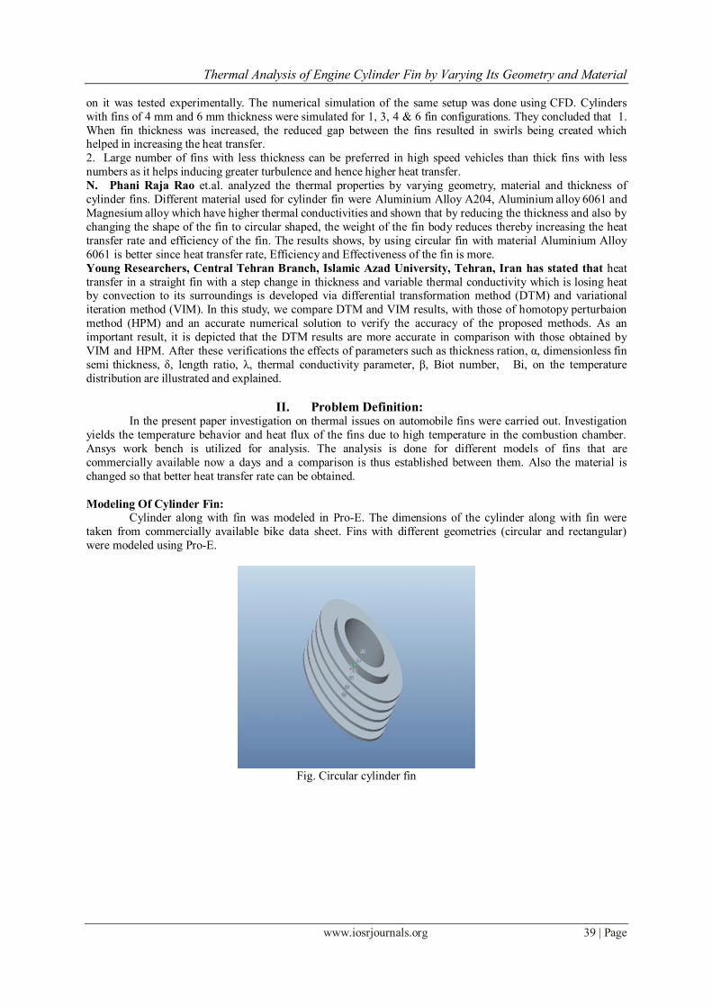
Cylinder along with fin was modeled in Pro-E. The dimensions of the cylinder along with fin were
taken from commercially available bike data sheet. Fins with different geometries (circular and rectangular)
were modeled using Pro-E.
Fig. Circular cylinder fin
Thermal Analysis of Engine Cylinder Fin by Varying Its Geometry and Material
www.iosrjournals.org 40 | Page
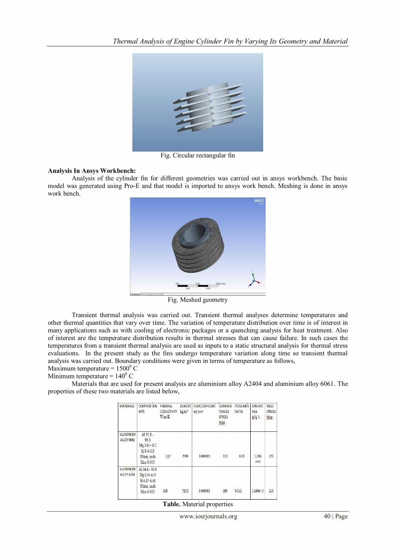
Fig. Circular rectangular fin
Analysis In Ansys Workbench:
Analysis of the cylinder fin for different geometries was carried out in ansys workbench. The basic
model was generated using Pro-E and that model is imported to ansys work bench. Meshing is done in ansys
work bench.
Fig. Meshed geometry
Transient thermal analysis was carried out. Transient thermal analyses determine temperatures and
other thermal quantities that vary over time. The variation of temperature distribution over time is of interest in
many applications such as with cooling of electronic packages or a quenching analysis for heat treatment. Also
of interest are the temperature distribution results in thermal stresses that can cause failure. In such cases the
temperatures from a transient thermal analysis are used as inputs to a static structural analysis for thermal stress
evaluations. In the present study as the fins undergo temperature variation along time so transient thermal
analysis was carried out. Boundary conditions were given in terms of temperature as follows,
Maximum temperature = 15000 C
Minimum temperature = 1400 C
Materials that are used for present analysis are aluminium alloy A2404 and aluminium alloy 6061. The properties of these two materials are listed below,
Table. Material properties
Thermal Analysis of Engine Cylinder Fin by Varying Its Geometry and Material
www.iosrjournals.org 41 | Page
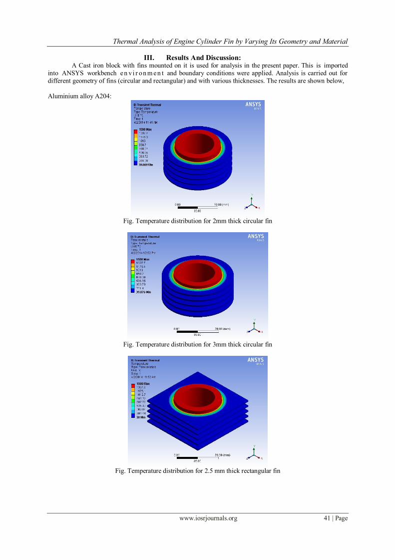
III. Results And Discussion: A Cast iron block with fins mounted on it is used for analysis in the present paper. This is imported
into ANSYS workbench e n v i r on m e n t and boundary conditions were applied. Analysis is carried out for
different geometry of fins (circular and rectangular) and with various thicknesses. The results are shown below,
Aluminium alloy A204:
Fig. Temperature distribution for 2mm thick circular fin
Fig. Temperature distribution for 3mm thick circular fin
Fig. Temperature distribution for 2.5 mm thick rectangular fin

Thermal Analysis of Engine Cylinder Fin by Varying Its Geometry and Material
www.iosrjournals.org 42 | Page
Aluminium alloy 6061
Fig. Temperature distribution for 2.5 mm thick circular fin
Fig. Temperature distribution for 2 mm thick rectangular fin
Fig. Temperature distribution for 3 mm thick rectangular fin
Thermal Analysis of Engine Cylinder Fin by Varying Its Geometry and Material
www.iosrjournals.org 43 | Page
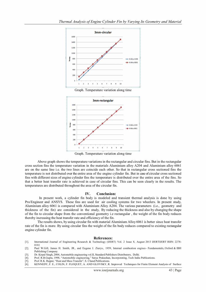
Graph. Temperature variation along time
Graph. Temperature variation along time
Above graph shows the temperature variations in the rectangular and circular fins. But in the rectangular
cross section fins the temperature variation in the materials Aluminium alloy A204 and Aluminium alloy 6061 are on the same line i.e. the two lines are coincide each other. So that in rectangular cross sectioned fins the
temperature is not distributed over the entire area of the engine cylinder fin. But in case of circular cross sectioned
fins with different sizes of engine cylinder fins the temperature is distributed over the entire area of the fins. So
that a better heat transfer rate is achieved in case of circular fins. This can be seen clearly in the results. The
temperatures are distributed throughout the area of the circular fin.
IV. Conclusion: In present work, a cylinder fin body is modeled and transient thermal analysis is done by using
Pro/Engineer and ANSYS. These fins are used for air cooling systems for two wheelers. In present study, Aluminium alloy 6061 is compared with Aluminium Alloy A204. The various parameters (i.e., geometry and
thickness of the fin) are considered in the study, By reducing the thickness and also by changing the shape
of the fin to circular shape from the conventional geometry i.e rectangular , the weight of the fin body reduces
thereby increasing the heat transfer rate and efficiency of the fin.
The results shows, by using circular fin with material Aluminium Alloy 6061 is better since heat transfer
rate of the fin is more. By using circular fins the weight of the fin body reduces compared to existing rectangular
engine cylinder fin.
References: [1]. International Journal of Engineering Research & Technology (IJERT) Vol. 2 Issue 8, August 2013 IJERTIJERT ISSN: 2278-
0181
[2]. Paul W.Gill, James H. Smith, JR., and Eugene J. Ziurys., 1959, Internal combustion engines - Fundamentals, Oxford & IBH
Publishing Company.
[3]. Dr. Kirpal Singh, 2004, Automobile engineering vol.II, Standard Publishers Distributors, Delhi.
[4]. Prof. R.B.Gupta, 1998, “Automobile engineering,” Satya Prakashan, Incorporating, Tech India Publications.
[5]. Prof. R.K. Rajput, “Heat and Mass Transfer”, S. Chand Publications.
[6]. KENNEDY, F. E., COLIN, F. FLOQUET, A. AND GLOVSKY, R. Improved Techniques for Finite Element Analysis of Surface

Thermal Analysis of Engine Cylinder Fin by Varying Its Geometry and Material
www.iosrjournals.org 44 | Page
Temperatures. Westbury House page 138-150, (1984).
[7]. COOK, R. D. Concept and Applications of Finite Element Analysis, Wiley, Canada, (1981).
[8]. BEEKER, A.A. The Boundary Element Method in Engineering, McGraw-Hill, New York, (1992).
[9]. ZIENKIEWICZ, O. C. The Finite Element method, McGraw-Hill, New York, (1977).