The New Methods of Graphite Nodules Detection in Ductile Cast Iron
8
This article was downloaded by: [McMaster University] On: 15 October 2013, At: 05:21 Publisher: Taylor & Francis Informa Ltd Registered in England and Wales Registered Number: 1072954 Registered office: Mortimer House, 37-41 Mortimer Street, London W1T 3JH, UK Materials and Manufacturing Processes Publication details, including instructions for authors and subscription information: http://www.tandfonline.com/loi/lmmp20 The New Methods of Graphite Nodules Detection in Ductile Cast Iron A. R. Kiani-Rashid a & S. A. Rounaghi a a Department of Materials Engineering, Faculty of Engineering , Ferdowsi University of Mashhad , Mashhad, Iran Published online: 24 Mar 2011. To cite this article: A. R. Kiani-Rashid & S. A. Rounaghi (2011) The New Methods of Graphite Nodules Detection in Ductile Cast Iron, Materials and Manufacturing Processes, 26:2, 242-248, DOI: 10.1080/10426914.2010.520788 To link to this article: http://dx.doi.org/10.1080/10426914.2010.520788 PLEASE SCROLL DOWN FOR ARTICLE Taylor & Francis makes every effort to ensure the accuracy of all the information (the “Content”) contained in the publications on our platform. However, Taylor & Francis, our agents, and our licensors make no representations or warranties whatsoever as to the accuracy, completeness, or suitability for any purpose of the Content. Any opinions and views expressed in this publication are the opinions and views of the authors, and are not the views of or endorsed by Taylor & Francis. The accuracy of the Content should not be relied upon and should be independently verified with primary sources of information. Taylor and Francis shall not be liable for any losses, actions, claims, proceedings, demands, costs, expenses, damages, and other liabilities whatsoever or howsoever caused arising directly or indirectly in connection with, in relation to or arising out of the use of the Content. This article may be used for research, teaching, and private study purposes. Any substantial or systematic reproduction, redistribution, reselling, loan, sub-licensing, systematic supply, or distribution in any form to anyone is expressly forbidden. Terms & Conditions of access and use can be found at http:// www.tandfonline.com/page/terms-and-conditions
-
Upload
independent -
Category
Documents
-
view
1 -
download
0
Transcript of The New Methods of Graphite Nodules Detection in Ductile Cast Iron
This article was downloaded by: [McMaster University]On: 15 October 2013, At: 05:21Publisher: Taylor & FrancisInforma Ltd Registered in England and Wales Registered Number: 1072954 Registered office: Mortimer House,37-41 Mortimer Street, London W1T 3JH, UK
Materials and Manufacturing ProcessesPublication details, including instructions for authors and subscription information:http://www.tandfonline.com/loi/lmmp20
The New Methods of Graphite Nodules Detection inDuctile Cast IronA. R. Kiani-Rashid a & S. A. Rounaghi aa Department of Materials Engineering, Faculty of Engineering , Ferdowsi University ofMashhad , Mashhad, IranPublished online: 24 Mar 2011.
To cite this article: A. R. Kiani-Rashid & S. A. Rounaghi (2011) The New Methods of Graphite Nodules Detection in DuctileCast Iron, Materials and Manufacturing Processes, 26:2, 242-248, DOI: 10.1080/10426914.2010.520788
To link to this article: http://dx.doi.org/10.1080/10426914.2010.520788
PLEASE SCROLL DOWN FOR ARTICLE
Taylor & Francis makes every effort to ensure the accuracy of all the information (the “Content”) containedin the publications on our platform. However, Taylor & Francis, our agents, and our licensors make norepresentations or warranties whatsoever as to the accuracy, completeness, or suitability for any purpose of theContent. Any opinions and views expressed in this publication are the opinions and views of the authors, andare not the views of or endorsed by Taylor & Francis. The accuracy of the Content should not be relied upon andshould be independently verified with primary sources of information. Taylor and Francis shall not be liable forany losses, actions, claims, proceedings, demands, costs, expenses, damages, and other liabilities whatsoeveror howsoever caused arising directly or indirectly in connection with, in relation to or arising out of the use ofthe Content.
This article may be used for research, teaching, and private study purposes. Any substantial or systematicreproduction, redistribution, reselling, loan, sub-licensing, systematic supply, or distribution in anyform to anyone is expressly forbidden. Terms & Conditions of access and use can be found at http://www.tandfonline.com/page/terms-and-conditions
Materials and Manufacturing Processes, 26: 242–248, 2011Copyright © Taylor & Francis Group, LLCISSN: 1042-6914 print/1532-2475 onlineDOI: 10.1080/10426914.2010.520788
The New Methods of Graphite Nodules Detectionin Ductile Cast Iron
A. R. Kiani-Rashid and S. A. Rounaghi
Department of Materials Engineering, Faculty of Engineering,Ferdowsi University of Mashhad, Mashhad, Iran
The properties of nodular ductile cast iron are strongly influenced by morphology, size and distribution of graphite particles. Nodular ductileirons have spheroidal graphites in the as-cast state. In this work, these nodules are characterized by means of light optical microscopy (LOM)and electron microscopy (EM). Experimental data are represented by LOM. Metallography is processed to obtain an image where the graphitenodules are clearly distinguished from the similar inclusions which make doubts in microstructure characterization; this is formed by completelyunconventional procedures. EM was used to show more clear aspects of granular graphite in cast irons. These data can provide a valid supporttowards a more confident quality control in the ductile iron production.
Keywords Ductile iron; Echant; EM; Graphite; LOM.
Introduction
The nodular irons are relatively inexpensive, andspecial properties such as a high degree of ductility andshock resistance are achieved by modifying the form ofthe graphite. For their interesting mechanical properties,nodular graphite cast iron has been a topic of growinginterest in engineering productions. The success of ductileiron means that it currently accounts for about 20 to 30% ofthe cast irons used in the most industrialized countries [1].Spheroidal graphite (SG) cast iron microstructure
comprises free carbon (graphite) not combined into carbidesand exists as nodules of graphite dispersed into a matrixof steel type. Ductile cast iron has higher strength andtoughness than grey cast iron with flake graphite form.Deviation from nodular graphite to flake graphite introducesa lower strength because the flakes act as easy crack pathsand stress concentrators in the metal. By modifying thegraphite to spheroidal form, a higher level of tensile strengthand ductility can be achieved [2, 3].Generally, the form of the graphite characterizes the
cast iron microstructures. Changes in the shape, size, anddistribution of graphite can be caused by numerous factorssuch as alloying elements, melting temperature, and coolingrate. Morrogh and Williams [4] reported that obtaining anodular structure in an alloy with appreciable sulfur contentis impossible. They suggested that an appropriate amountof cerium, which is a desulphuriser, should be added tothe melt to ensure a nodular graphite structure. Thomasand Gruzleski [5] have suggested that the nodular form ofgraphite is the normal and preferred growth morphology ofgraphite.
Received June 7, 2010; Accepted August 30, 2010Address correspondence to A. R. Kiani-Rashid, Department of
Materials Engineering, Faculty of Engineering, Ferdowsi Universityof Mashhad, P.O. Box. 91775-1111, Mashhad, Iran; Fax: 0098 (511)8763305; E-mail: [email protected] and [email protected]
Graphite is a hexagonal-close pack form of carbon thatcan grow in both the liquid and solid states of iron.Theoretically, in irons above the eutectic compositionof carbon, the graphite first nucleates in the liquid andthen continues to grow in the solid. In irons below theeutectic composition, the graphite does not start to growuntil the iron reaches eutectic temperature. As seen in amicrostructure, the larger nodules are from growth initiatedin the liquid, and the smaller nodules are from growth thatdoes not start until solidification temperatures are reached.Graphite is composed of a series of stacked parallel layer
planes shown schematically in Fig. 1, with the trigonalsp2 bonding. In Fig. 1, the circles showing the positionof the carbon atoms do not represent the actual size ofthe atom. Each atom, in fact, contacts its neighbors [6].Within each layer plane, the carbon atom is bonded to threeothers, forming a series of continuous hexagons in whatcan be considered as an essentially infinite two-dimensionalmolecule [6].The most common stacking sequence of the graphite
crystal is hexagonal (alpha) with a -ABABAB- stackingorder [6]. Atoms can add much more easily in the -a-directions as compared with the -c- direction; Double andHellawell [7] explained that if the layer lattice is rolled toa sphere, the possibility of molecular addition in the -c-direction will be increased. They believed that the hexagonalmonolayer or graphone sheets freely precipitate from themolten metal solution and reported that impurities in themelt such as oxygen and/or sulfur would promote the growthof graphite sheets in the -c- direction, which leads to theflake graphite form.Baihe Miao et al. [8] illustrated many fanlike structures,
which are aggregates of graphite platelets forming aspheroid of graphite. In addition, Baihe Miao et al. [9]suggested, based upon the Double and Hellawell model, agraphite spherulite consisting of conical helixes, in whichthe {0001} planes of graphite within each conical helix
242
Dow
nloa
ded
by [
McM
aste
r U
nive
rsity
] at
05:
21 1
5 O
ctob
er 2
013

NEW METHODS OF GRAPHITE NODULES DETECTION 243
Figure 1.—Crystal structure of graphite showing -ABABAB- stackingsequence and unit cell [4].
grow out of the graphite platelets. They believed thatcrystallographic defects present in the graphite structurecould change normal growth of the spherulite and lead tobending or branching of the crystal within the basal plane.The interplatelet area illustrates that the spiral growth ofgraphite is not perfect.The present study has been conducted to the as-cast
samples. The aim of this work is to acquire the structuralinformation about graphite detection in experimental castiron so there is no doubt between this kind of phaseswith foreign particles such as inclusions and impuritieswhich are reported occasionally instead of graphite in themetallography of cast irons. In this article, the problem ofidentification and characterization of the graphite noduleshas been considered, and a novel qualitative analysisprocedure has been developed based on a chemical etchanttechnique. This is a kind of methodology for image analysisof the material metallographic specimen’s pictures thatprovide a reliable and efficient separation of the elementsof interest from the background and the evaluation of theirmorphological characteristics.
Experimental
Experimental ductile irons with the compositions givenin Table 1 were produced in a Morgan gas-fired furnaceand a high-frequency melting plant of 20kg capacity. Thesandwich technique was used to treat the melt of each
iron with a ferrosilicon alloy containing 5%Mg at 1400�C.Finally, post-inoculation of ferrosilicon containing 75% Siwas carried out in the crucible. Standard Y-block sandmoulds and permanent moulds were used to ensure a soundcasting.Quantitative measurements of the carbon content in the
experimental irons were made using equipment at SwindenTechnology Centre of Corus Group PLC (formerly BritishSteel Ltd.).The compositions selected resulted in more than
90% nodularity of graphite. Optical microscopy andscanning electron microscopy (SEM) were used toexamine and delineate any variations in the microstructure.Light optical microscopes (LOM) were used to analyzemetallographically prepared specimens, etched with a Nital2% for 10s. Furthermore, a solution containing 20g iodinein 1000ml of alcohol, known as iodine solution or iodinetincture, has been used to colorize graphite nodules inductile cast iron.For scanning electron microscopy, a Cambridge Series
3 SEM fitted with a Link 860 series 1 EDX systemand a Cambridge Series 4 SEM were used. For thecharacterization of microstructure, a working distancebetween 20–24mm was chosen, and an accelerating voltageof 20kV and spot size between 4–6nm.The successful preparation of transmission electron
microscopy (TEM) thin foils from cast iron is morecomplicated than most kinds of metal alloys and steels,because there are two quite different phases (iron andgraphite) in cast iron. When Jet polishing is used, a darksurface due to strong oxidation and corrosion can beobtained, and the detachment of large graphite nodules cantake place before adequate thinning. The preparation of athin foil from the bulk samples was only achieved by a morelaborious process of mechanical polishing and ion thinningas follows:
1) Specimens were cut to sections approximately 250�mthick, using a Struers Accutom-2 slitting machine;
2) Discs of 3mm diameter were punched from thesesections;
3) The 3mm diameter disks were mechanically polished to80–100�m thickness;
4) The central specimen area was dimpled to 10–20�mthickness using a Gatan precision dimple grinder model656; and
5) The samples were ion beam thinned, initially under a15� inclination angle and finally 10�, for times rangingfrom 2hr to 24hr depending on initial thickness, using aGatan dual ion milling machine model 600 beam thinnerand a Gatan precision ion polishing system model 691PIPSTM V4.31.
Table 1.—Composition of irons, wt%.
Alloy C Al Si Ni Mn P S Mg Fe
0.48% Al 3.68 0.48 1.06 0.04 0.06 <0�005 <0�005 0.05 Balance1.77% Al 3.58 1.71 1.18 0.04 0.07 <0�005 <0�005 0.05 –4.88% Al 3.44 4.88 1.22 0.05 0.10 <0�005 <0�005 0.05 –
Dow
nloa
ded
by [
McM
aste
r U
nive
rsity
] at
05:
21 1
5 O
ctob
er 2
013
244 A. R. KIANI-RASHID AND S. A. ROUNAGHI
The Gatan Model 656 Dimple Grinder is a precisioninstrument used for grinding circular dimples, of sphericalor flat bottomed profile, in the surface of materials suchas ceramics, semiconductors, and metals. The principalapplication is the preparation of TEM specimens.If specimen blanks are mechanically dimpled prior to
final thinning, then the finished specimen has a larger thanusual electron transparent area of a more uniform thicknessand, in the case ion or neutral particle beam thinningsystems, the time required for final thinning is significantlyreduced. Moreover, the specimen has a relatively thick rimsurrounding the thin region and is thus very robust.A careful operator can routinely produce thickness less
than 5�m, although in the case of most metals, a finalthickness between 20�m and 50�m is more normal sincemechanical damage introduced into the specimen surfaceby the action of grinding must be removed. The preparationof such specimens is completed by electropolishing, ionbeam thinning, etc. However, the Dimple Grinder is gentleenough and provides sufficient control over the process ofdimpling.The thin foils were examined using a Philips CM20 TEM
operating at an accelerating voltage of 200kV. Identificationof the structure and the phases present in the experimentalspecimens was determined with a series of bright field (BF)and dark field (DF) images and the corresponding electrondiffraction patterns (DP).
Results and discussions
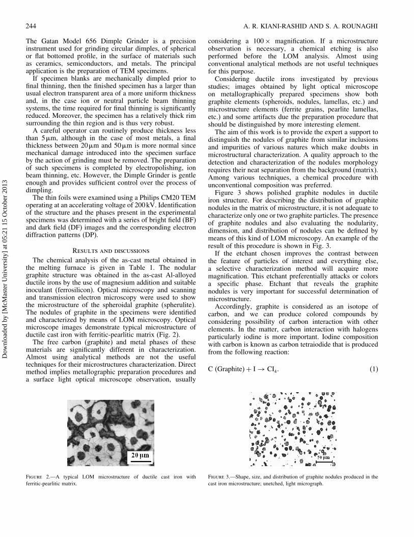
The chemical analysis of the as-cast metal obtained inthe melting furnace is given in Table 1. The nodulargraphite structure was obtained in the as-cast Al-alloyedductile irons by the use of magnesium addition and suitableinoculant (ferrosilicon). Optical microscopy and scanningand transmission electron microscopy were used to showthe microstructure of the spheroidal graphite (spherulite).The nodules of graphite in the specimens were identifiedand characterized by means of LOM microscopy. Opticalmicroscope images demonstrate typical microstructure ofductile cast iron with ferritic-pearlitic matrix (Fig. 2).The free carbon (graphite) and metal phases of these
materials are significantly different in characterization.Almost using analytical methods are not the usefultechniques for their microstructures characterization. Directmethod implies metallographic preparation procedures anda surface light optical microscope observation, usually
Figure 2.—A typical LOM microstructure of ductile cast iron withferritic-pearlitic matrix.
considering a 100× magnification. If a microstructureobservation is necessary, a chemical etching is alsoperformed before the LOM analysis. Almost usingconventional analytical methods are not useful techniquesfor this purpose.Considering ductile irons investigated by previous
studies; images obtained by light optical microscopeon metallographically prepared specimens show bothgraphite elements (spheroids, nodules, lamellas, etc.) andmicrostructure elements (ferrite grains, pearlite lamellas,etc.) and some artifacts due the preparation procedure thatshould be distinguished by more interesting element.The aim of this work is to provide the expert a support to
distinguish the nodules of graphite from similar inclusionsand impurities of various natures which make doubts inmicrostructural characterization. A quality approach to thedetection and characterization of the nodules morphologyrequires their neat separation from the background (matrix).Among various techniques, a chemical procedure withunconventional composition was preferred.Figure 3 shows polished graphite nodules in ductile
iron structure. For describing the distribution of graphitenodules in the matrix of microstructure, it is not adequate tocharacterize only one or two graphite particles. The presenceof graphite nodules and also evaluating the nodularity,dimension, and distribution of nodules can be defined bymeans of this kind of LOM microscopy. An example of theresult of this procedure is shown in Fig. 3.If the etchant chosen improves the contrast between
the feature of particles of interest and everything else,a selective characterization method will acquire moremagnification. This etchant preferentially attacks or colorsa specific phase. Etchant that reveals the graphitenodules is very important for successful determination ofmicrostructure.Accordingly, graphite is considered as an isotope of
carbon, and we can produce colored compounds byconsidering possibility of carbon interaction with otherelements. In the matter, carbon interaction with halogensparticularly iodine is more important. Iodine compositionwith carbon is known as carbon tetraiodide that is producedfrom the following reaction:
C (Graphite)+ I → CI4� (1)
Figure 3.—Shape, size, and distribution of graphite nodules produced in thecast iron microstructure; unetched, light micrograph.
Dow
nloa
ded
by [
McM
aste
r U
nive
rsity
] at
05:
21 1
5 O
ctob
er 2
013

NEW METHODS OF GRAPHITE NODULES DETECTION 245
Table 2.—Some physical properties of carbon tetraiodide and iodoform.
Molecular formula Molar mass Appearance Density Melting point Crystal structure
CI4 519.63g/mol Red crystals 4.32g/cm3 171�C MonoclinicCHI3 393.73g/mol Yellowish crystals 4.008g/cm3 123�C Hexagonal
The carbon tetraiodide �CI4� is a tetrahalomethane. Beingbright red, it is a relatively rare example of a highly coloredmethane derivative. CI4 is slightly reactive towards water,giving iodoform and I2. Otherwise, it is soluble in nonpolarorganic solvents. It is decomposed by hot alcohol, givingiodoform and iodine. The compound iodoform �CHI3� isa pale yellow, crystalline, and volatile substance. Somephysical properties of carbon tetraiodide and iodoform arelisted in Table 2.A typical light microscopy (LM) micrograph of cast iron
microstructure after detection of graphite by tincture ofiodine at room temperature for 5 minutes is shown in Fig. 4.According to Eq. (1), carbon in the form of graphite noduleschanges to carbon tetraiodide and appears bright red.The specimen was then immersed in container containing
hot tincture of iodine for 5 minutes. The solutiontemperature was around 65�C. During this time, graphiteparticles in ductile iron interacted with hot iodine solutionand produced carbon tetraiodide. This compound is notstable in hot alcohol and is decomposed to iodoform withpale yellow color (Fig. 5). This procedure may be useful fordistinguishing graphite from similar particles or inclusionssuch as MnS in iron structures.It is evident that the graphite nodules are apparent by
quite different color in the darker background. The resultantimages show that hot tincture of iodine solution is asuitable etchant for clarifying the graphite nodules in themicrostructure (Fig. 5). For the as-cast cast iron, a gradualappearance of graphite is observed while the solution ofetchant remains in contact with samples for longer etchingtime.The experimental results are completed by electron
microscopy (SEM and TEM images) that let us considermore than one technique for better judgments.The microscopic observation showed that the
microstructure normally consists of nodular graphitein a ferritic-pearlitic matrix. Figure 6 show a typical
Figure 4.—A typical LM micrograph of cast iron microstructure afterdetection of graphite by tincture of iodine at room temperature for 5 minutes.According to Eq. (1), carbon in the form of graphite nodules changes to carbontetraiodide and appears bright red.
Figure 5.—A typical LM micrograph of cast iron microstructure afterdetection of graphite by hot tincher of iodine.
microstructure of the iron containing 1.71% Al, in whichthe volume fraction of graphite present in the iron is about12%. Figure 7 shows SEM micrographs of the experimentalductile irons with 0.48% and 4.88% Al content. As can beseen the graphite nodules are dispersed randomly in themicrostructure (Fig. 3).Some previous studies [10, 11] gave a description of
the microstructure of the spheroids. Conventional methodsused in structural metallurgy have been associated toelectron microscopy which is a powerful testing method fordetermination of the graphite in these irons.Figure 8 shows TEM micrographs from the ductile iron
at two different magnifications. Figure 8(a) illustrates threegraphite nodules at low magnification. Some nodule cross-sections were thin enough for TEM examination of thegraphite structure. Based on TEM observations, formationof spheroidal or plate-like particles morphology of graphitesnodules is presented. A bright field image of a section athigh magnification is shown in Fig. 8(b). The structure ofthe spherulite is built up by aggregation of graphite plateletsto produce a fanlike structure. This structure consists ofgraphite platelets and interplatelet regions. This observationis consistent with previous studies performed on two kindsof nodular silicon irons [8, 9]. Figure 9 shows another TEMmicrograph of the cross-section of a graphite nodule. Thebright field image illustrates the layered morphology of the
Figure 6.—A typical SEM micrograph of the spheroid morphology in theas-cast state of cast iron. The sample etched by nital 2%.
Dow
nloa
ded
by [
McM
aste
r U
nive
rsity
] at
05:
21 1
5 O
ctob
er 2
013
246 A. R. KIANI-RASHID AND S. A. ROUNAGHI
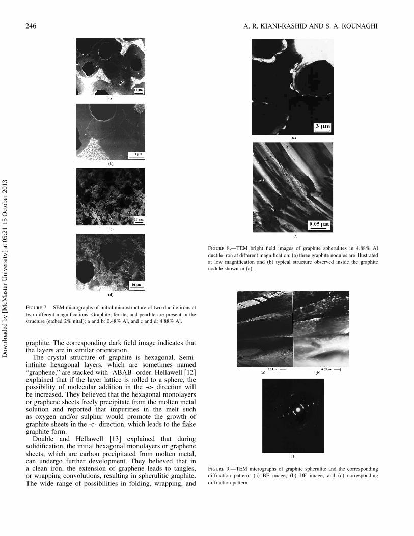
Figure 7.—SEM micrographs of initial microstructure of two ductile irons attwo different magnifications. Graphite, ferrite, and pearlite are present in thestructure (etched 2% nital); a and b: 0.48% Al, and c and d: 4.88% Al.
graphite. The corresponding dark field image indicates thatthe layers are in similar orientation.The crystal structure of graphite is hexagonal. Semi-
infinite hexagonal layers, which are sometimes named“graphene,” are stacked with -ABAB- order. Hellawell [12]explained that if the layer lattice is rolled to a sphere, thepossibility of molecular addition in the -c- direction willbe increased. They believed that the hexagonal monolayersor graphene sheets freely precipitate from the molten metalsolution and reported that impurities in the melt suchas oxygen and/or sulphur would promote the growth ofgraphite sheets in the -c- direction, which leads to the flakegraphite form.Double and Hellawell [13] explained that during
solidification, the initial hexagonal monolayers or graphenesheets, which are carbon precipitated from molten metal,can undergo further development. They believed that ina clean iron, the extension of graphene leads to tangles,or wrapping convolutions, resulting in spherulitic graphite.The wide range of possibilities in folding, wrapping, and
Figure 8.—TEM bright field images of graphite spherulites in 4.88% Alductile iron at different magnification: (a) three graphite nodules are illustratedat low magnification and (b) typical structure observed inside the graphitenodule shown in (a).
Figure 9.—TEM micrographs of graphite spherulite and the correspondingdiffraction pattern: (a) BF image; (b) DF image; and (c) correspondingdiffraction pattern.
Dow
nloa
ded
by [
McM
aste
r U
nive
rsity
] at
05:
21 1
5 O
ctob
er 2
013
NEW METHODS OF GRAPHITE NODULES DETECTION 247
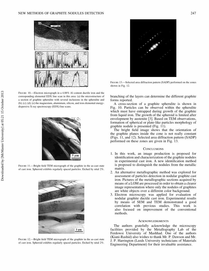
Figure 10.—Electron micrograph in a 4.88% Al content ductile iron and thecorresponding elemental EDX line scan in this area: (a) the microstructure ofa section of graphite spherulite with several inclusions in the spherulite and(b); (c); (d); (e) the magnesium, aluminium, silicon, and iron elemental energy-dispersive X-ray spectroscopy (EDX) line scans.
Figure 11.—Bright field TEM micrograph of the graphite in the as-cast stateof cast iron. Spheroid exhibits regularly spaced particles. Etched by nital 2%.
Figure 12.—Bright field TEM micrograph of the graphite in the as-cast stateof cast iron. Spheroid exhibits regularly spaced particles. Etched by nital 2%.
Figure 13.—Selected area diffraction pattern (SADP) performed on the zonesshown in Fig. 12.
branching of the layers can determine the different graphiteforms reported.A cross-section of a graphite spherulite is shown in
Fig. 10. Particles can be observed within the spherulitewhich must have entrapped during growth of the graphitefrom liquid iron. The growth of the spheroid is limited afterenvelopment by austenite [3]. Based on TEM observations,formation of spherical or plate-like particles morphology ofgraphite nodule is presented (Fig. 11).The bright field image shows that the orientation of
the graphite planes inside the cone is not really constant(Figs. 11, and 12). Selected area diffraction pattern (SADP)performed on these zones are given in Fig. 13.
Conclusions
1. In this work, an image production is proposed foridentification and characterization of the graphite nodulesin experimental cast iron. A new identification methodis proposed to distinguish the nodules from the metallicmatrix.
2. An alternative metallographic method was explored forassessment of particles detection in nodular graphite castiron. Pictures of the metallographic sections acquired bymeans of a LOM are processed in order to obtain a clearerimage representation where only the nodules of graphitesare white objects over a different color background.
3. Electron microscopy was applied for evaluation ofnodular graphite ductile cast iron. Experimental resultsby means of SEM and TEM demonstrated a goodcorrelation with previous studies. This work isalso focused on improvement of the conventionalmethods.
Acknowledgments
The authors gratefully acknowledge the microscopyfacilities provided by the Metallography Lab of theFerdowsi University of Mashhad. One of the authors(Kiani-Rashid) also wishes to thank Mr. P. Dawson and Mr.J. P. Harrington (Leeds University technicians of MaterialsEngineering Department) for their invaluable assistance.
Dow
nloa
ded
by [
McM
aste
r U
nive
rsity
] at
05:
21 1
5 O
ctob
er 2
013

248 A. R. KIANI-RASHID AND S. A. ROUNAGHI
References
1. Hughes, I.C.H. Ductile iron. In Metals Handbook, Casting,9th Ed., Vol. IS; BClRA International Center for Cast MetalsTechnology: South Yorkshire, UK, 1988; 647–666.
2. Angus, H.T. Cast Iron, Physical and Engineering Properties;ButterWorths and Co. (Publishers) Ltd.: London, 1978.
3. Elliot, R. Cast Iron Technology; ButterWorths and Co.(Publishers) Ltd.: London, 1988.
4. Morrogh, H.; Williams, W.J. The production of nodular graphitestructures in cast iron. JISI 1948, March, 306–322.
5. Thomas, P.M.; Gruzleski, J.E. The nucleation and growth ofgraphite: The modification of cast iron. J. Iron Steel Inst. 1973,211, 426.
6. Pierson, H.O. Handbook of Carbon, Graphite, Dimond, andFullerenes Properties, Processing and Applications; Publishedby William Andrew Inc., 1993; 44–45.
7. Double, D.D.; Hellawell, A. The structure of flake graphite inNi-C eutectic alloy. Acta Metallurgical 1969, 17, 1071–1083.
8. Miao, B.; Fang, K.; Bianan, W.; Liu, G. On the microstructureof graphite spherulites in cast irons by TEM and HREM. ActaMetall. Mater. 1990, 38, 2167–2174.
9. Miao, B.; North Wood, D.O.; Bian, W.; Fang, K.; Fan,M.H. Structure and growth of platelets in graphite spherulitesin cast iron. Journal of Materials Science 1994, 29,255–261.
10. Kiani-Rashid, A.R. The influence of aluminum and heat treatmentconditions on austempered ductile irons. Ph.D. Thesis, Universityof Leeds, UK. 2000.
11. Kiani-Rashid, A.R.; Edmonds, D.V. Int. Journal of Engineering,Transactions B: Applications 2002, 15 (3), 261–272.
12. Double, D.D.; Hellawell, A. The nucleation and growth ofgraphite, The modification of cast iron. Acta Metall. Mater. 1995,43 (6), 2435–2442.
13. Double, D.D.; Hellawell, A. The structure of flake graphitein Ni-C eutectic alloy. ACTA Metallurgica Aug. 1969, 17,1071–1083.
Dow
nloa
ded
by [
McM
aste
r U
nive
rsity
] at
05:
21 1
5 O
ctob
er 2
013