Advanced Processing of Nickel-Titanium-Graphite Based ...
78
Cleveland State University Cleveland State University EngagedScholarship@CSU EngagedScholarship@CSU ETD Archive 2019 Advanced Processing of Nickel-Titanium-Graphite Based Metal Advanced Processing of Nickel-Titanium-Graphite Based Metal Matrix Composites Matrix Composites Amit K. Patil Follow this and additional works at: https://engagedscholarship.csuohio.edu/etdarchive Part of the Mechanical Engineering Commons How does access to this work benefit you? Let us know! How does access to this work benefit you? Let us know! Recommended Citation Recommended Citation Patil, Amit K., "Advanced Processing of Nickel-Titanium-Graphite Based Metal Matrix Composites" (2019). ETD Archive. 1151. https://engagedscholarship.csuohio.edu/etdarchive/1151 This Thesis is brought to you for free and open access by EngagedScholarship@CSU. It has been accepted for inclusion in ETD Archive by an authorized administrator of EngagedScholarship@CSU. For more information, please contact [email protected].
-
Upload
khangminh22 -
Category
Documents
-
view
6 -
download
0
Transcript of Advanced Processing of Nickel-Titanium-Graphite Based ...

Cleveland State University Cleveland State University
EngagedScholarship@CSU EngagedScholarship@CSU
ETD Archive
2019
Advanced Processing of Nickel-Titanium-Graphite Based Metal Advanced Processing of Nickel-Titanium-Graphite Based Metal
Matrix Composites Matrix Composites
Amit K. Patil
Follow this and additional works at: https://engagedscholarship.csuohio.edu/etdarchive
Part of the Mechanical Engineering Commons
How does access to this work benefit you? Let us know! How does access to this work benefit you? Let us know!
Recommended Citation Recommended Citation Patil, Amit K., "Advanced Processing of Nickel-Titanium-Graphite Based Metal Matrix Composites" (2019). ETD Archive. 1151. https://engagedscholarship.csuohio.edu/etdarchive/1151
This Thesis is brought to you for free and open access by EngagedScholarship@CSU. It has been accepted for inclusion in ETD Archive by an authorized administrator of EngagedScholarship@CSU. For more information, please contact [email protected].

ADVANCED PROCESSING OF NICKEL-TITANIUM-GRAPHITE BASED METAL
MATRIX COMPOSITES
AMIT PATIL
Bachelor of Engineering in Mechanical Engineering
University of Mumbai
May 2013
submitted in partial fulfillment of requirements for the degree
MASTER OF SCIENCE IN MECHANICAL ENGINEERING
at the
CLEVELAND STATE UNIVERSITY
May 2019

We hereby approve this thesis
For
AMIT PATIL
Candidate for the Master of Science degree
or the Department of
Mechanical Engineering
And
CLEVELAND STATE UNIVERSITY’S
College of Graduate Studies by
Dr. Tushar Borkar
Department and Date
Dr. Majid Rashidi
Department and Date
Dr. Somnath Chattopadhyay
Department and Date
05/03/2019
Student’s Date of Defense

ACKNOWLEDGMENTS
I am extremely grateful to my advisor Dr. Tushar Borkar for his persistent support
and moral assistance in research as well as academics during my master’s program. I am
also thankful for his guidance and endless encouragement throughout this entire research.
I would like to sincerely express my gratitude towards Dr. Majid Rashidi and Dr.
Somnath Chattopadhyay for being involved in the thesis committee.
I am thankful to Dr. Rajeev Gupta from Department of Chemical & Biomolecular
Engineering at The University of Akron for helping me with X-Ray diffraction
characterization. Also, I would like to thank Profs. Raj Banerjee and Thomas Scharf from
department of Material Science and Engineering at University of North Texas, Denton for
helping me with LENSTM processing and tribology test in this research.
I am forever indebted, and I must express my profound gratitude to my parents
Kalyansing Patil and Vidya Patil along with my beloved brother Sagar for their support
and keeping me motivated to achieve my dreams.
This work is partially supported by the National Science Foundation under Grant
No. 1126126.

iv
ADVANCED PROCESSING OF NICKEL-TITANIUM-GRAPHITE BASED METAL
MATRIX COMPOSITES
AMIT PATIL
ABSTRACT
A new class of in situ titanium carbide (TiC)/graphite (C) reinforced nickel matrix
composites with variation in composition particularly varying C/Ti ratio have been
processed using two different processing techniques. Firstly, via mechanical alloying (MA)
followed by spark plasma sintering (SPS), i.e. solid-state processing. Secondly, using Laser
engineered net shaping (LENSTM) technique, i.e. metal additive manufacturing technique.
Mechanical alloying has gained special attention as a powerful non-equilibrium process
for fabricating amorphous and nanocrystalline materials, whereas spark plasma sintering
is a unique technique for processing dense and near net shape bulk alloys with
homogeneous microstructure. Laser engineered net shaping (LENSTM) is a rapid
prototyping technique prominently known for its ability to fabricate full dense complex
components and functionally graded materials. These composites consist of an in situ
formed and homogeneously distributed TiC precipitates reinforcing the nickel matrix.
Additionally, by tailoring the C/Ti ratio in these composites the volume fraction of TiC
reinforcement can be altered, and an additional graphitic phase can also be engineered into
the microstructure. These Ni-TiC-C composites exhibit excellent microhardness as well as
tribological properties as compared to pure nickel. Additionally, microstructure,
microhardness and tribological behavior of SPS processed Ni-TiC-C composites have been
investigated and compared with LENSTM processed counterparts. SPS processed Ni-Ti-C
composites exhibit excellent mechanical, as well as tribological properties as compared to

v
LENSTM processed samples primarily due to uniformly distributed refined TiC and
graphite phases within nickel matrix.

vi
TABLE OF CONTENTS
Page
ABSTRACT ....................................................................................................................... iv
LIST OF TABLES ........................................................................................................... viii
LIST OF FIGURES ........................................................................................................... ix
CHAPTER
I. INTRODUCTION .............................................................................................1
1.1. Metal Matrix Composites (MMCs) .............................................................1
1.2. Objectives ....................................................................................................5
1.3. Organization of thesis ..................................................................................5
II. METHODOLOGY ............................................................................................7
2.1. Powder metallurgy .......................................................................................7
2.2. Mechanical Alloying (MA) ..........................................................................8
2.3. Spark Plasma Sintering (SPS) ....................................................................11
2.4. Laser Engineered Net shaping (LENSTM)..................................................14
2.5. Nickel Titanium Carbide ............................................................................18
III. EXPERIMENTAL METHODS .....................................................................21
3.1. Processing using mechanical alloying followed by
spark plasma sintering...............................................................................21
3.2. Processing using Laser engineered net shaping .........................................24
3.3. Characterization of Ni-Ti-C composites ....................................................26

vii
IV. RESULTS, DISCUSSION, AND COMPARISON .......................................30
4.1. SPS processed Ni-Ti-C composites ...........................................................30
4.2. LENSTM processed Ni-Ti-C composites ....................................................47
4.3. SPS process vs LENSTM process ...............................................................57
V. CONCLUSION ..............................................................................................59
REFERENCES ..................................................................................................................61

viii
LIST OF TABLES
TABLE Page
I. Nominal composition of SPS processed sample in atomic weight percentage ...........22
II. Nominal composition of LENSTM processed sample in atomic weight percentage ....24

ix
LIST OF FIGURES
FIGURE Page
1. Schematic of mechanical alloying kinematics and Mechanical alloying process .........9
2. Schematic illustration of the SPS system ....................................................................12
3. Schematic illustration of the LENSTM system .............................................................16
4. Schematic illustration of Bragg’s Law ........................................................................26
5. XRD pattern for SPS processed composites ................................................................31
6. Backscattered images of pure nickel ............................................................................33
7. Backscattered images of Ni-10Ti-5C ...........................................................................34
8. Backscattered images of Ni-10Ti-10C .........................................................................35
9. Backscattered images of Ni-5Ti-10C ...........................................................................36
10. Backscattered images of Ni-7Ti-20C ...........................................................................37
11. Backscattered images of Ni-6Ti-20C ...........................................................................38
12. Backscattered images of Ni-5Ti-20C ...........................................................................39
13. Backscattered images of Ni-4Ti-20C ...........................................................................40
14. Backscattered images of Ni-3Ti-20C ...........................................................................41
15. Vickers microhardness of SPS processed samples ......................................................43
16. Vickers indent impression............................................................................................44
17. Steady state friction of SPS processed samples ...........................................................45
18. XRD pattern for LENSTM processed composites.........................................................47
19. Backscattered images of LENSTM processed samples .................................................49
20. Pseudo binary section of ternary Ni-Ti-C system ........................................................50
21. Ternary phase diagram of Ni-Ti-C system ..................................................................51

x
22. Backscattered images of LENSTM processed samples .................................................52
23. Vickers microhardness of LENSTM processed samples ...............................................53
24. Steady state friction of LENSTM processed samples....................................................55
25. EDS maps of Ni-10Ti-10C ..........................................................................................56
26. Microhardness comparison of SPS and LENSTM processed samples ..........................57

1
CHAPTER I
INTRODUCTION
1.1. Metal Matrix Composites (MMCs)
Metal matrix composite is a class of material, consisting of a metal matrix
reinforced with ceramic particulates making it suitable for numerous functional as well as
structural applications.1-3 Metal matrix composites have very high strength to weight ratio,
also exhibit attractive physical and mechanical properties, superior than those of a base
metal matrix, as well as ceramic reinforcement. MMCs can be used at elevated temperature
due to combination of metallic properties such as high strength, modulus and ceramic
properties such as high hardness and wear resistance.1-3 The balance of such attractive
properties, availability of relatively inexpensive reinforcements, various processing routes,
and inherent flexibility to alter the characteristics and properties by varying the nominal
compositions make it an ideal material for aerospace, energy, automotive and structural
engineering applications.1-5
Depending upon desired application, metal matrix composites can be reinforced
with ceramic particles, continuous and non-continuous fibers, or even hybrid
reinforcement, consisting of both particles and fibers. Out of all these, particulate
reinforced MMCs are considered as the most attractive material due to their low production

2
cost and their isotropic properties.25 Generally, reinforcement particulates used in MMCs
are ceramics such as metal carbides (TiC, SiC, WC, TaC), metal nitrides (TiN, TaN, ZrN,
Si3N4), metal borides (WB, TiB2), and metal oxides (Al2O3, ZrO2) exhibiting excellent
mechanical properties. These ceramic reinforcements exhibit high Young’s modulus, high
thermal stability, high yield strength, high hardness, high melting temperature, low density,
and low coefficient of thermal expansion. These properties can be tailored with production
as well as processing techniques, and with the matrix system selected in the composite
materials. Out of all the ceramic reinforcement particulates, metal carbides are most
commonly used primarily due to their very high mechanical strength to the metal matrix.
Selection of processing routes to fabricate MMCs, mainly depends upon applications and
desired properties. Factors such as size and volume fraction of the reinforcement phase
and nature of the interfacial bonding between matrix and reinforcement affect the
microstructure and mechanical as well as tribological properties of the composites.6-8
Depending on the formation of reinforcement during processing, MMCs are
classified as ex situ and in situ. The first synthesis route uses a conventional technique of
composite fabrication in which reinforcement are externally added to the metal matrix.
Whereas, in in situ MMCs, formation of reinforcement takes place within the matrix. Ex
situ has disadvantages as compared to in situ MMCs such as poor interfacial bond, size
restriction of the reinforcement, and poor wettability, resulting in the inhomogeneous
distribution of the reinforcement particulates as compared with in situ technique. Also,
surface contamination, and particulate agglomeration can be seen in particulate reinforced
ex situ MMCs. Homogeneous dispersion of fine and thermally stable reinforcement in the
metal matrix is desirable to achieve optimal mechanical properties and enhanced

3
mechanical performance of MMC. Thus, the interfacial bonding between metal matrix and
ceramic reinforcement need to be stable as it influences the structure and the properties of
the MMC. By using the in situ technique of fabrication, the reinforcement is synthesized
in the metal matrix during fabrication process due to exothermic chemical reaction between
the constituents, thus resulting in a strong and clean interfacial bonding between metal
matrix and fine scale size of reinforcement precipitates.8,12 A more homogeneous
microstructure and remarkably improved mechanical properties are achieved due to
homogeneous dispersion of particles within metal matrix, control over the size, good
wettability of the reinforcement particulates with the metal matrix allowing good
coherency, and excellent interfacial bonding between metal matrix and ceramic
reinforcement. Also, the in-situ reinforcement phases formed due to the chemical reaction
are found to be thermodynamically stable in the metal matrix than that of ex situ MMCs.7,8
Therefore due to several shortcomings of ex situ processing route, in situ processing route
is most preferable for the fabrication of MMCs.
K. K. Chawla, in his work, has classified the fabrication techniques for MMCs in
two categories, liquid-state processing, and solid-state processing.36 MMCs can be
fabricated using different processing techniques such as casting, forging, and powder
metallurgy processing, etc. Processing routes for fabrication of MMCs play an important
role in altering their microstructures, thus affecting their mechanical properties. Powder
metallurgy method is most widely applied for processing MMCs, due to low cost and its
inherent flexibility to alter the composition in order to get precisely tailored mechanical
properties.

4
The size of the in situ formed reinforcement particles in MMCs depend on various
factors such as external force, pressure and temperature during reaction, etc. Depending
upon the processing temperature of the metal matrix and the reactants, S.C. Tjong has
classified the Powder metallurgy process routes for in situ reaction into four categories:
a) Solid-Liquid reaction process, b) Liquid-Liquid reaction process, c) Solid-Solid reaction
process, d) Vapor-Liquid reaction process.12 These processing routes play an important
role in altering the microstructure as well as mechanical properties of the material
synthesized.
In present study, Titanium carbide (TiC)-graphite(C) reinforced Nickel matrix
composites were fabricated by powder metallurgy technique using solid-solid and solid-
liquid reaction process. Mechanical alloying (MA), which falls under solid-solid reaction
process is a solid-state processing method and was used for in situ formation of
reinforcement phase which was later consolidated using spark plasma sintering (SPS). In
solid liquid reaction process, the reinforcement phase is formed in the matrix solvent via
diffusion reaction. Laser Engineered Net shaping (LENSTM) technique was used in this
study for fabrication of MMCs using solid-liquid reaction process. In both processing
routes, in situ MMCs have been processed using elemental blend nickel, titanium, and
graphite powder particles.
5
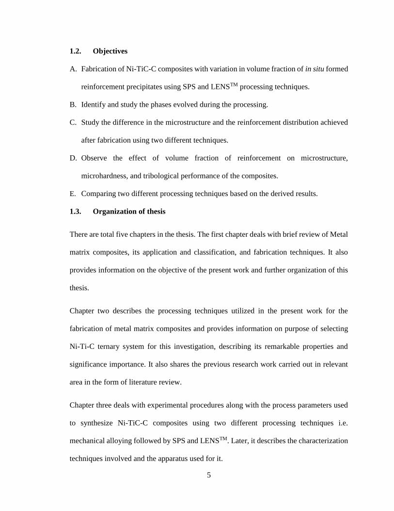
1.2. Objectives
A. Fabrication of Ni-TiC-C composites with variation in volume fraction of in situ formed
reinforcement precipitates using SPS and LENSTM processing techniques.
B. Identify and study the phases evolved during the processing.
C. Study the difference in the microstructure and the reinforcement distribution achieved
after fabrication using two different techniques.
D. Observe the effect of volume fraction of reinforcement on microstructure,
microhardness, and tribological performance of the composites.
E. Comparing two different processing techniques based on the derived results.
1.3. Organization of thesis
There are total five chapters in the thesis. The first chapter deals with brief review of Metal
matrix composites, its application and classification, and fabrication techniques. It also
provides information on the objective of the present work and further organization of this
thesis.
Chapter two describes the processing techniques utilized in the present work for the
fabrication of metal matrix composites and provides information on purpose of selecting
Ni-Ti-C ternary system for this investigation, describing its remarkable properties and
significance importance. It also shares the previous research work carried out in relevant
area in the form of literature review.
Chapter three deals with experimental procedures along with the process parameters used
to synthesize Ni-TiC-C composites using two different processing techniques i.e.
mechanical alloying followed by SPS and LENSTM. Later, it describes the characterization
techniques involved and the apparatus used for it.

6
Chapter four describes the results and discussion based on the processing routes as well as
characterization techniques used and mentioned in previous chapters. This chapter
concludes with comparing microstructure, mechanical, and tribological properties of Ni-
TiC-C composites processed via SPS and LENSTM processing routes.
Lastly, chapter five summarizes the results and concludes the present work.

7
CHAPTER II
METHODOLOGY
This chapter provides understanding on the methods and processing techniques
utilized for the fabrication of metal matrix composites in the present work and highlights
the importance of mechanical alloying (MA), spark plasma sintering (SPS), laser
engineered net shaping (LENSTM), and Ni-Ti-C ternary system used in this study.
Furthermore, it also provides brief literature review on the research work previously carried
out in relevant area.
2.1. Powder metallurgy
Powder metallurgy process is known for its rapid production method of accurately
fabricating components and offers control over the microstructure and characteristic
properties. Powder metallurgy offers precision and flexibility to control the features and
the characteristics of the part fabricated, which is very difficult or near impossible to
achieve using any other conventional processing techniques. It also eliminates additional
machining operations as involved in casting, and other traditional techniques to achieve
final dimension.28
The powder metallurgy technique has an excellent set of advantages such as it
enables efficient material utilization and fabrication of complex components with near net

8
shape possible, fabrication of components using hard materials such as WC, TiC, and
components can be fabricated in pure form as the purity of precursors used gets preserved
throughout the process. It also makes utilization of wide variety of materials such as metals,
alloys, ceramics and other immiscible systems possible.29
The recent development in powder metallurgy has helped in developing novel
alloys with better mechanical properties in order to crater the current industrial demands.
It has also boosted and helped in development for the wide spectrum of additive
manufacturing techniques. Powder metallurgy technique has helped manufacturing of pre
alloyed powders which can be used by additive manufacturing process for the fabrication
of complex components with improved mechanical performance. Powder metallurgy
process has opened new routes to process advanced materials with controlled
microstructure using processes such as mechanical alloying and rapid solidification
processing (RSP).
2.2. Mechanical Alloying
Mechanical alloying (MA) is an effective solid-state powder processing technique
permitting the development of refined microstructure and nanocrystalline size of
homogeneously dispersed in situ reinforcement which improves the mechanical properties
of the composite while retaining the ductility of the metal matrix.12,13 Mechanical alloying
is a unique process allowing the production of advanced materials, which was difficult or
impossible to fabricate with traditional techniques.

9
Figure 1. Schematic of mechanical alloying kinematics and mechanical alloying process
It is a mechanochemical process by which in situ ceramic reinforcement can be
induced in the composite via mechanically activated chemical reaction using elemental
powders. It has been showed that in situ formation of composites leads to better properties
in comparison with conventionally synthesized composites.30,31 The process starts with the
blending of elemental powder in required proportion and is subjected to high energetic
compressive impact forces in a mill using grinding media until a steady state is achieved.
MA is considered as a complex stochastic process having numerous independent and
interdependent process variables involved and depend on factors such as the desired
phases, microstructures, and properties. Depending upon these factors, selection and
optimization of these variables are required in order to obtained MMCs with desired
properties.13 MA has been proven capable of processing a wide variety of materials such
as intermetallic alloys, Ceramics, and other refractory materials. Both miscible and
immiscible systems material systems can be processed using MA. Mechanically alloyed
materials possess high strength and are found to be stable at both room temperature and
elevated temperature.13

10
C Suryanarayana reported that during MA, repetitive fracturing, cold welding and
rewelding governs the shape and size of the milled powders which increases the wettability
and results in better dispersion of reinforcement in the metal matrix by breaking up the
ceramic clusters.13 Previous studies have indicated that particle size has significant
influence on the recrystallisation process affecting grain size and microstructure of the
sintered composites.13-15 It is well known that grain size refinement of metallic materials
to nanoscale enhances mechanical properties such as strength and hardness of the material
maintaining the original ductility.24 Hall-Petch relationship states that grain size has a great
influence on the composite strength as they as it acts as a pinning point and hinders the
dislocation movement.59 Thus, ball milling was performed to reduce the particulate size
and for homogeneous dispersion of the in situ reinforcement precipitates within the metal
matrix.

11
2.3. Spark Plasma Sintering (SPS)
Spark plasma sintering (SPS) also known as Field assisted sintering technique
(FAST) is a novel consolidation technique suitable to sinter metal, alloys and composites
at relatively low temperatures below their melting point and shorter sintering time
compared to the conventional techniques. It has a high heating rate, shorter holding time,
and low sintering temperature which retards the grain growth retaining refined
microstructure and increases the microhardness as well as mechanical properties of the
composites.16-19,47 In SPS, consolidation of powder is taking place due to microscopic
discharge of pulsed direct current between particles under uniaxial pressure, promoting
densification during sintering. Melting of the surface of the powder takes place due to
resistive joules heating effect energized by DC pulsed electric current.20,21
The composite samples processed via SPS technique can achieve full densification,
and grain growth can also be avoided due to rapid heating up to 1000oC/min as well as
shorter holding time. This ability to reach the processing temperature in a short duration of
time due to high heating rate, minimizes the processing time required for sintering.48,49 In
SPS process, part porosity can be controlled by changing the processing parameters such
as applied pressure, holding time and processing temperature.50 In SPS, sintering takes
place in shorter cycle time; thus, limiting grain growth and preventing undesired phase
transformation or intermetallic reaction of the material during processing. The SPS
technique also possesses numerous other advantages. For example, it is less sensitive to
initial material characteristics, it can consolidate difficult to sinter material, no need of
sintering aids, no cold compaction required before sintering as needed in other techniques
and helps achieving improved characteristic properties of the consolidated material. These

12
outstanding advantages make the SPS process preferable over other conventional
techniques of sintering.51
The material sintered using SPS process can be both conductive and non-
conductive. Conductive material is heated by resistive joules heating effect and by heat
transfer from the die. Whereas, in case of non-conductive material, heating takes place only
through heat transfer from the die.51 Previous work has demonstrated that a wide variety of
conducting or insulating materials such as metals, ceramics, and composites can be
processed using the SPS technique.47-49
Figure 2: Schematic illustration of the SPS system

13
Figure 2. shows schematic of SPS system. In the SPS technique, the powder to be
sintered is placed in a graphite die when low pressure, typically less than 100MPa is
applied. However, if the applied pressure is more than 100MPa, tungsten carbide die is
used. Graphite foil is used inside the die and in the assembly to improve the conductivity.
Die and Punches of the same material are used. Uniaxial pressure is applied with the help
of plungers, blocks, and cold spacer assembly, requiring all of them to be electrically
conductive. Generally, graphite, stainless steel, or copper is used in the assembly.51,53 If the
applied pressure is less 100MPa, graphite is most preferred due to its high thermal
conductivity.
In this process, the powder particles are sintered due to the surface evaporation and
melting of the powder surface followed by solidification during cooling. Due to
microscopic discharge of pulsed DC current between particles, a local high temperature
state of several hundreds to thousands of degrees centigrade is formed. This high
temperature causes evaporation and melting on the surface of the powder particles and neck
formation around the contact area between the particles takes place. Also, the flow of
material due to plasticity and under applied pressure brings particles together and promotes
necking. This processing phenomenon under applied pressure, allows sintering through
SPS at lower temperatures as compared with other processing techniques.51,52 The amount
of current required during the SPS cycle depends on factors such as die geometry,
processing temperature, conductivity of the material processed, etc. For high heating rates,
large sizes of die, and high processing temperature, a higher current is required. In present
study, SPS 10-3 by Thermal Technologies was used. This system can apply up to 10000

14
kg of pressure, 3000 Amps and 10 volts of current. Generally, the pulse DC signal is ON
for 30ms, and OFF for 2ms
Several research works were carried out on fabrication of in situ MMCs via SPS
preceded by high energy mechanical alloying using ball mill and a substantial improvement
in mechanical properties particularly, in terms of mechanical strength, wear resistance,
hardness, thermal conductivity was observed. It was also noticed that even after
consolidation, the nanocrystalline size obtained via MA was preserved. 25,27,34
Currently, the industrial application is limited to the area where it is difficult to
process high performance materials using traditional techniques. Also, further machining
is required for the material consolidated through the SPS process but still you can get near-
net shape.
2.4. Laser Engineered Net Shaping (LENSTM)
Laser Engineered Net Shaping (LENSTM) is an additive manufacturing technique
first developed at Sandia National laboratory in the United States and was subsequently
commercialized by Optomec Inc. It is a directed energy deposition technique and solid
metal forming process for the fabrication of 3d components. Due to its rapid cooling and
high solidification rate, it is advantageous in achieving homogeneous as well as refined
microstructure with improved mechanical properties as compared with other conventional
methods. LENSTM is an additive manufacturing technique prominently known for its
ability to fabricate full dense, complex components as well as functionally graded
materials.

15
Application of LENSTM technique includes rapid prototyping, low volume
manufacturing, and product development for aerospace, medical and defense industries,
and surface engineering applications. This technique has the flexibility to deposit material
on existing or pre-deposited, makes it possible to repair. Material restrictions, such as it
can only use spherical metal powders with a size range of 50µm – 150µm is used as a raw
material for fabrication.37 Unlike other rapid prototyping techniques, no plastic-coated
materials, filler materials, or binders is required in this processing technique. The
fabrication of component takes place under controlled inert Argon environment in the
hermetically sealed glove box with oxygen content as low as 10ppm, to prevent
contamination, and avoiding the formation of any undesired intermetallic phases. Figure 3.
depicts the working schematic of LENSTM process.

16
Figure 3: Schematic illustration of the LENSTM system54
Depending on the material to be deposited, and power output required, Nd-YAG or
fiber laser can be used to process various types of elemental powders. It has a four co-axial
nozzle powder feeder system; it is designed in such a way that all the nozzles are focused
at a point where the laser beam is focused. Delivery of elemental powder from the powder
hoppers through the nozzle is carried out with the help of inert gas delivery system. The
high-power density from the focused laser beam generates a melt pool on surface of the
substrate or previously deposited layer. The substrate is moved relative to the laser beam
to deposit thin layers of controlled width and thickness. The movement of the substrate and
the flow rate of powder is controlled by the control system. Powder through the delivery

17
system is sprayed and absorbed in the melt pool. Due to small melt pool geometry and
rapid cooling rate, this component fabricated using this component has very fine refined
microstructure with fine grain size.38,39 Materials such as stainless-steel alloys, tool steel
alloys, titanium alloys, nickel and nickel based super alloys, cobalt alloys and other
composite materials have been fabricated via LENSTM.
LENSTM system uses multiple hoppers for powder feeder which add to its flexibility
and make it possible to fabricate compositional graded components. This ability makes it
possible for deposition of functionally graded materials (FGMs). FGMs are advanced
materials, whose composition and the microstructure change gradually from one direction
to other. Its main characteristic is its graded composition and microstructure, resulting in
variation of properties. This tailored composition and microstructure of the components,
helps in achieving distribution of properties as desired for wide range of applications. [40,41]
FGMs can be processed via several methods such as CVD, Plasma spraying, Powder
Metallurgy, SHS, LENSTM, etc. But due to limitation of shape and size of the die in pressure
aided sintering. LENSTM process is most suited for the fabrication of FGMs.42
Some examples of previous work carried out on fabrication of MMCs using
LENSTM and demonstrating its efficacy, includes laser based fabrication of IN625 based
MMCs with Ni-coated and uncoated TiC particles as reinforcement by Zheng et al.43, WC-
Co cermets fabricated by Xiong et al.44, Liu et al worked on fabrication of FGM TiC/Ti
composites using LENSTM process42, deposition of Ti-6Al-V4 using LENSTM.46

18
2.5. Nickel-Titanium Carbide-Graphite
Nickel exhibits various attractive properties such as excellent corrosion and wear
resistance, ductility, toughness and has a low coefficient of thermal expansion. Owing to
its properties such as heat resistance, resistant to fatigue and abrasion, resistant to oxidation
and its ability to retain its shape and strength even at high temperature, nickel and nickel-
based superalloys has been widely used in aerospace, petrochemical industry and numerous
other processing industries.7,8 Nickel based MMCs with ceramic reinforcement are used
for various industrial applications including operations involved with cutting, stamping,
punching, rolling, piercing, etc.3
Titanium Carbide (TiC) is a refractory material with excellent combination of
properties such as high hardness of 3200 (HV), high Young's modulus (440 GPa), low
density (4.93 g/cm3), low coefficient of friction, excellent corrosion and wear resistance,
high melting point (32000C), resistant to abrasion, and infusibility. These remarkable
properties make TiC an ideal candidate as ceramic reinforcement adding high mechanical
strength to the metal matrix.7-12
TiC has high hardness value but is extremely brittle thus cannot be used as
monolithic ceramic for direct engineering application. Therefore, TiC is a prominent
reinforcement material in ductile and tough Nickel base metal matrix and makes an
excellent hybrid material for automotive, petrochemical, aerospace and high-temperature
structural applications where high compressive strength, low coefficient of friction, and
high wear resistance are required at elevated temperatures. It is also known that as
compared to other metals, nickel exhibits a low wetting angle with Titanium carbide, thus
leading to an improved interfacial bonding in TiC reinforced nickel matrix.7 Nickel has
19
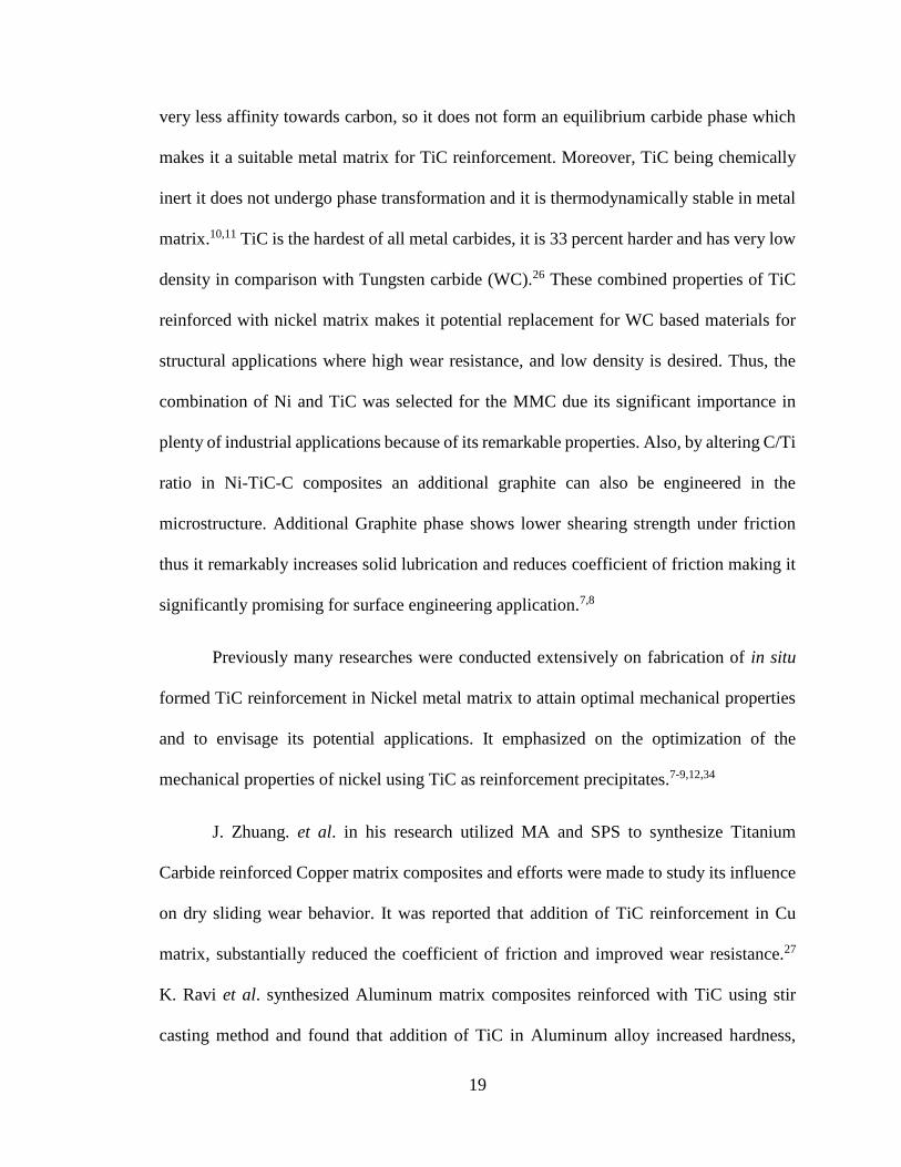
very less affinity towards carbon, so it does not form an equilibrium carbide phase which
makes it a suitable metal matrix for TiC reinforcement. Moreover, TiC being chemically
inert it does not undergo phase transformation and it is thermodynamically stable in metal
matrix.10,11 TiC is the hardest of all metal carbides, it is 33 percent harder and has very low
density in comparison with Tungsten carbide (WC).26 These combined properties of TiC
reinforced with nickel matrix makes it potential replacement for WC based materials for
structural applications where high wear resistance, and low density is desired. Thus, the
combination of Ni and TiC was selected for the MMC due its significant importance in
plenty of industrial applications because of its remarkable properties. Also, by altering C/Ti
ratio in Ni-TiC-C composites an additional graphite can also be engineered in the
microstructure. Additional Graphite phase shows lower shearing strength under friction
thus it remarkably increases solid lubrication and reduces coefficient of friction making it
significantly promising for surface engineering application.7,8
Previously many researches were conducted extensively on fabrication of in situ
formed TiC reinforcement in Nickel metal matrix to attain optimal mechanical properties
and to envisage its potential applications. It emphasized on the optimization of the
mechanical properties of nickel using TiC as reinforcement precipitates.7-9,12,34
J. Zhuang. et al. in his research utilized MA and SPS to synthesize Titanium
Carbide reinforced Copper matrix composites and efforts were made to study its influence
on dry sliding wear behavior. It was reported that addition of TiC reinforcement in Cu
matrix, substantially reduced the coefficient of friction and improved wear resistance.27
K. Ravi et al. synthesized Aluminum matrix composites reinforced with TiC using stir
casting method and found that addition of TiC in Aluminum alloy increased hardness,
20
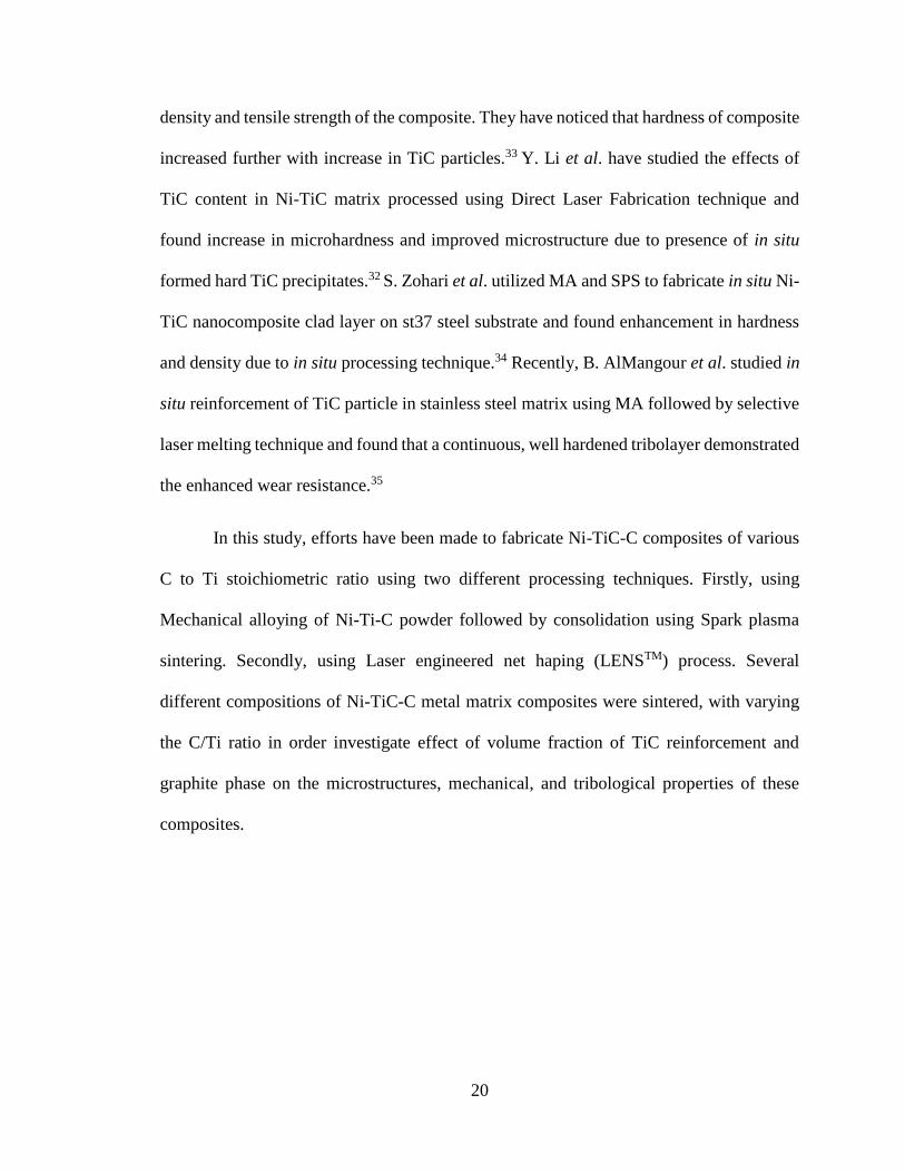
density and tensile strength of the composite. They have noticed that hardness of composite
increased further with increase in TiC particles.33 Y. Li et al. have studied the effects of
TiC content in Ni-TiC matrix processed using Direct Laser Fabrication technique and
found increase in microhardness and improved microstructure due to presence of in situ
formed hard TiC precipitates.32 S. Zohari et al. utilized MA and SPS to fabricate in situ Ni-
TiC nanocomposite clad layer on st37 steel substrate and found enhancement in hardness
and density due to in situ processing technique.34 Recently, B. AlMangour et al. studied in
situ reinforcement of TiC particle in stainless steel matrix using MA followed by selective
laser melting technique and found that a continuous, well hardened tribolayer demonstrated
the enhanced wear resistance.35
In this study, efforts have been made to fabricate Ni-TiC-C composites of various
C to Ti stoichiometric ratio using two different processing techniques. Firstly, using
Mechanical alloying of Ni-Ti-C powder followed by consolidation using Spark plasma
sintering. Secondly, using Laser engineered net haping (LENSTM) process. Several
different compositions of Ni-TiC-C metal matrix composites were sintered, with varying
the C/Ti ratio in order investigate effect of volume fraction of TiC reinforcement and
graphite phase on the microstructures, mechanical, and tribological properties of these
composites.

21
CHAPTER III
EXPERIMENT METHODS
3.1. Processing using Mechanical alloying followed by Spark Plasma Sintering
(SPS)
Elemental powders of Nickel (3-7 µm, 99.9% pure), Titanium (-325 mesh, 99.5%
pure) and Graphite (-325 mesh, 99% pure) were selected as a starting precursor. These
powders were sourced from Alfa Aesar. Samples were stoichiometrically mixed in several
different nominal compositions with varying atomic weight percentage of Nickel,
Titanium, and Graphite as shown in Table I. The blend of these elemental powders was
then mechanically alloyed using high energy ball milling (HEBM) equipment.
For brevity, the powders mixed with the nominal composition 80at%Ni-10at%Ti-
10at%C is further referred as Ni-10Ti-10C. Similarly, this will be followed for all other
Ni-Ti-C composites. The compositions with varying atomic weight ratio of Carbon to
Titanium (C/Ti) are listed in Table I.
22
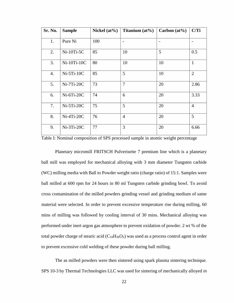
Sr. No. Sample Nickel (at%) Titanium (at%) Carbon (at%) C/Ti
1. Pure Ni 100 - - -
2. Ni-10Ti-5C 85 10 5 0.5
3. Ni-10Ti-10C 80 10 10 1
4. Ni-5Ti-10C 85 5 10 2
5. Ni-7Ti-20C 73 7 20 2.86
6. Ni-6Ti-20C 74 6 20 3.33
7. Ni-5Ti-20C 75 5 20 4
8. Ni-4Ti-20C 76 4 20 5
9. Ni-3Ti-20C 77 3 20 6.66
Table I: Nominal composition of SPS processed sample in atomic weight percentage
Planetary micromill FRITSCH Pulverisette 7 premium line which is a planetary
ball mill was employed for mechanical alloying with 3 mm diameter Tungsten carbide
(WC) milling media with Ball to Powder weight ratio (charge ratio) of 15:1. Samples were
ball milled at 600 rpm for 24 hours in 80 ml Tungsten carbide grinding bowl. To avoid
cross contamination of the milled powders grinding vessel and grinding medium of same
material were selected. In order to prevent excessive temperature rise during milling, 60
mins of milling was followed by cooling interval of 30 mins. Mechanical alloying was
performed under inert argon gas atmosphere to prevent oxidation of powder. 2 wt % of the
total powder charge of stearic acid (C18H36O2) was used as a process control agent in order
to prevent excessive cold welding of these powder during ball milling.
The as milled powders were then sintered using spark plasma sintering technique.
SPS 10-3 by Thermal Technologies LLC was used for sintering of mechanically alloyed in
23
situ Ni-Ti-C composite powder. The SPS process was programmed by specific sets of
operation instructions such in the software, ITools. Set points for temperature, applied force
with rate, heating rate, dwell time, ramp up/ramp down time were assigned in the program.
The sintering process was carried out at 11000C with a heating rate of 100 0C/min
under maximum uniaxial pressure of 50 MPa with dwell time of 5 minutes. A cylindrical
graphite die of 20mm inner diameter was used. An optical pyrometer was used to yield the
temperature inside the die.
The SPS consolidated samples were mounted on graphite based conductive resin at
359OF under 4000 psi. The mounted samples resulted into one and quarter inch specimen,
making it easier to hold and polish the sample. The mounted samples were then
mechanically polished using abrasive silicon carbide (SiC) paper having high friability to
remove external graphite layer. The samples were polished sequentially using 240, 400,
600, 800 and 1200 grit SiC paper. Polishing was carried out under constant supply of water
for cooling and removal of debris. Final lustrous metallographic finish was achieved by
polishing using micro-cloth and 0.04µm colloidal silica solution. The samples were then
washed in an ultrasonicate using soap solution, water and ethanol rinse each respectively
for microstructural characterization.

24
3.2. Processing using Laser engineered net shaping (LENSTM)
Elemental powder of Nickel (40-150 µm), Titanium (40-150 µm) and nickel coated
graphite powders (which can pass through -300/ +325 mesh) were selected as starting powder.
These powders were sourced from Alfa Aesar. All the powders were gas atomized. The
powders were stoichiometrically mixed in several different nominal compositions with
varying atomic weight percentage of nickel, titanium, and graphite as mentioned in Table
II.
Sr. No. Sample Nickel (at%) Titanium (at%) Carbon (at%) C/Ti
1. Pure Ni 100 - - -
2. Ni-10Ti-5C 85 10 5 0.5
3. Ni-10Ti-10C 80 10 10 1
4. Ni-7Ti-20C 73 7 20 2.86
5. Ni-3Ti-20C 77 3 20 6.66
Table II: Nominal composition of LENSTM processed sample in atomic weight percentage.
It is well known that variation in flow rate of powder is possible due to differences
in the density and irregularity in the surface. It has also shown that metal coated powder
particles improved flowability and the powder feeding, which was mainly due to increased
particle density, and smoother surface of the particle. [43] Thus, to avoid the flow variation
of the powders, nickel coated graphite powder was used instead of pure graphite powder.
Nickel coated graphite powder used had composition of 75wt% of C and 25wt% of Ni.
Four different nominal compositions with varying atomic weight percentage of nickel,
titanium and nickel coated graphite were stoichiometrically mixed twin-roller mixer. Twin-
roller mixer consist of two rollers moving in opposite direction. The powders were mixed

25
for 6 hours at 300rpm in order to achieve near homogeneous mixture. The powder mixture
was then loaded in the powder feeder of the LENSTM system.
Similar to other additive manufacturing technology, LENSTM process also begins
with computer-aided design (CAD) file of a three-dimensional component to be fabricated.
Fabrication is carried out by layer by layer deposition of the component on a nickel
substrate. Using the powder delivery system, the homogeneous mixture of powder was
ejected through the nozzle at a focused point which converges at a point where the high-
power laser beam is focused. In this experiment, a high powered 500W Nd: YAG laser
emitting near infrared laser radiation at a wavelength of 1.064µm was used. The Laser
beam was focused to create a melt pool of powder ejected on a substrate with the help of
inert argon gas flowing through a four-nozzle assembly. Subsequently, the substrate is
moved relative to the laser beam to deposit thin layers of controlled width and thickness.
Scan speed of 10 inches/min and hatch width of 0.018 inch and a layer thickness of 0.01
inch was used during the deposition. The layer deposition is carried out in a controlled
inert argon gas environment in the hermetically sealed glove box. The argon gas is
continuously recirculated at a flow rate of 3 liters/min throughout, and the oxygen content
was maintained below 10 parts per million (PPM) during deposition.
The in situ composites were deposited on the substrate in a cylindrical geometry of
diameter 10mm and height 10mm. These deposited composites were taken out from the
glove box through the anti-chamber present in the LENSTM system to avoid any
atmospheric oxygen contamination and were cut from the nickel base plate using electric
discharge machine. (EDM). These samples were then mounted and mechanically polished,
using same procedure as described in the previous section.

26
3.3. Characterization of Ni-Ti-C composites
3.3.1. X-Ray diffraction (XRD)
X ray diffraction technique was used to identify the phases present in the composite
samples. It works on the principle of Bragg’s Law, given by nλ = 2dsinƟ
Where, n= Integer determined by the given order, λ= Wavelength of the radiation in
angstrom (Å), d= Interplanar spacing in angstrom (Å), Ɵ= Angle of diffraction in radians.60
The radiations from the emitter are reflected at different planes at different angles
with variation in intensity which is detected by the detector. The emitter and detector are
rotated with variation in angle to complete a full scan of the sample, some of the incident
rays are reflected off the first atomic plane while some rays are reflected from the adjacent
atomic plane as shown in Figure 4.
Figure 4: Schematic illustration of Bragg’s Law
When the incident radiations are reflected from different planes meets each other,
constructive or destructive interference takes place. If the interference is destructive, it will
reflect low intensity and a flat line will appear. Constructive interference will occur when

27
a full phase shift in the rays takes place that is when the sum BC+CD is an integer and the
Bragg’s law fits true. In case of constructive interference, it will reflect an intensity peak
in XRD profile. Constructive interference occurs only at specific angles, depending upon
crystallography.60 These specific angles reveal the crystal structure of the phases present
in the sample. The results after analyzing the data determines hkl values of the crystal
planes. The X-ray diffraction data is plotted between the intensity (arbitrary units) of the
peaks versus the diffraction angle which was measured in 2Ɵ (degree).
In this experiment, tests were carried out in Rigaku SmartLab X-ray diffractometer.
XRD analyses was performed employing monochromatic Cukα radiation generated at 40
KV with a wavelength of 1.5402Å.
Following parameters were used to collect the data:
scan speed: 1.0 deg/min; step width: 0.04 deg; scan range: 20deg – 100deg
3.3.2. Scanning electron microscopy (SEM)
Additional characterization was done to observe the microstructure, phases and
study the effect of the processing techniques used, the composite samples processed using
SPS and LENSTM techniques were analyzed using scanning electron microscope (SEM).
Inspect F50 from FEI Corporation was used in obtaining secondary and backscattered
micrographs to investigate the morphology as well as phases present in these composites,
and to identify the effect of SPS and LENSTM processing technique on their microstructure.

28
3.3.3. Vickers Microhardness
Vickers microhardness was determined using Wilson VH1202 hardness tester from
Buehler having an accuracy of ±1.5%. Microhardness was evaluated under test force of 0.5
kgf and dwell time of 10 seconds as recommended by ASTM E384 standards. A pyramid
shaped diamond indenter was used for indentation. Indent diagonals were measured using
the measurement system in the Wilson DiaMet and the Vickers microhardness number was
calculated for the load and indent dimensions.
Vickers hardness number (VHN) is calculated using equation mentioned below,
VHN = 2Psin(α/2)/d2 = 1.854P/d2
Where, P is the test force in gram-force, d is the average of the diagonals of the indentation
in µm, α is the indenter tip angle which is taken as 136o.61
The test was carried out according to ASTM E384 standards. Test was performed
under ambient conditions and at least ten readings at different position were taken for each
sample.
3.3.4. Tribology
The dry sliding wear tests of the processed samples were conducted using Falex
ISC-200 Ball-on-disc system by Implant Sciences. Testing was carried out at room
temperature. Tests were performed under a normal load of 100g (1 N). The load (N), sliding
speed, and track radius is kept constant throughout the test. Coefficient of friction was
obtained from the ratio of tangential load to normal load. To show steady-state friction

29
behavior, tribological test was carried out in dry sliding conditions with sliding distance of
140m for each sample.
3.3.5. Energy Dispersive Spectroscopy
EDS characterization technique is a chemical analyzation technique used along
with SEM to identify the unknown material from its elemental phases and its relative
proportion present in the sample. This technique was used identify the phases and the
composition of the composite samples.

30
CHAPTER IV
RESULTS AND DISCUSSION
4.1. SPS processed Ni-Ti-C composites
4.1.1. X-Ray diffraction analysis
X-ray diffraction patterns for SPS processed Ni-Ti-C composites are shown in
Figure 5. From these patterns it is apparent that, Ni (FCC), TiC (NaCl-FCC) and C (HCP)
are the only principal phases present in these composite samples indicating no undesired
intermetallic phases or impurities were present in the sample. Absence of any peaks
corresponding to NiTi intermetallic phase shows no reaction between Nickel and Titanium.
Peaks corresponding (111), (200), and (220) crystallographic planes of FCC nickel,
whereas peaks corresponding (111), (200), (220) and (311) crystallographic planes of FCC
titanium carbide phase were observed at the position which agrees with the X-ray
diffraction data files of pure nickel and TiC.58

31
Figure 5: XRD pattern for SPS processed samples
From the characteristic peaks of TiC phase with FCC Bravais lattice, it is apparent
that Titanium and graphite have undergone an in situ reaction in order to form titanium
carbide (TiC). It also indicates the stability of TiC in the nickel matrix. Figure 5. Indicates
that Ni-10Ti-5C and Ni-10Ti-10C exhibited highest intensities for TiC peaks as compared
to other Ni-Ti-C composites. This increase in intensity of TiC peak in these composites are
primarily due to large volume fraction of TiC precipitates present in these composites.
In XRD analyses result, the presence of hcp (0002) carbon peak at ~260 in the XRD
pattern confirms the presence of Graphite phase in the composites. It is possible to engineer
an extra lubricious graphite phase by altering the C/Ti ratio. Also, intensity of (0002)
carbon peak increases with increasing C/Ti ratio, as carbon does not have solubility with

32
nickel and there is not much titanium available to react and form TiC. It was observed that
with increasing C/Ti ratio, the intensity of peak increases but later it decreases with increase
in intensity of (0002) Carbon peak as the C/Ti ratio increases further beyond 1.

33
4.1.2 Microstructural Analysis
The microstructural analysis of pure nickel and Ni-Ti-C composite samples were
characterized under FEI Inspect F50 equipped with backscattered electron detector.
Figure 6: Backscattered images of Pure Ni at a) 250X, b) 500X, c) 1KX, d) 2KX
magnification
Figure 6. shows SEM images of SPS processed pure nickel sample. Pure nickel
exhibits randomly oriented grains along with annealing twin boundaries which are clearly
seen in Figure 6. These annealing twins were formed due to relatively low stacking fault
energy of nickel thus reducing the total interfacial energy of the system. Also, the grain
size of pure nickel was observed in few microns ranging between 15µm to 30µm.

34
Figure 7: Backscattered images of Ni-10Ti-5C at a) 1KX, b) 10 KX, c) 25KX, d) 50KX
magnification
SEM images of SPS processed Ni-10Ti-5C are shown in Figure 7. It can be seen
clearly from the micrographs that nanosized TiC precipitates exhibiting spherical
morphology are homogeneously distributed within the randomly oriented nickel grains.
These uniformly distributed TiC precipitates help in retaining the refined nickel grains by
obstructing their grain growth during SPS processing. These uniformly distributed hard
TiC precipitates along with refined nickel microstructure contributes to the increase in
hardness of the composite by obstructing grain boundary dislocations during plastic
deformation.

35
Figure 8: Backscattered images of Ni-10Ti-10C at a) 1KX, b) 10 KX, c) 25KX, d) 50KX
magnification Figure 8 shows that Ni-10Ti-10C exhibits, uniform dispersion of TiC precipitates
within nickel matrix. Also, in SPS processed Ni-10Ti-10C sample, some unreacted
graphite was observed indicating that not all the titanium reacted with graphite for in situ
TiC formation, and maybe solid solution with nickel matrix is formed even though carbon
has negligible solubility with pure nickel. High volume fraction of homogeneously
distributed TiC precipitates is clearly seen in Figure 8. This was expected due to high
content (at%) of titanium and carbon as compared to Ni-10Ti-5C, which promotes in situ
TiC formation during mechanical alloying followed by SPS processing. Moreover, it was
also seen that due to higher C/Ti atomic ratio in Ni-10Ti-10C composites, the size as well

36
as volume fraction of TiC precipitates are larger as compared to Ni-10Ti-5C composites
still retaining their spherical morphology.
Figure 9: Backscattered images of Ni-5Ti-10C at a) 1KX, b) 10 KX, c) 25KX, d) 50KX
magnification
Figure 9. shows SEM images of Ni-5Ti-10C composites. The presence of extra graphite
phase exhibiting acicular morphology left after the reaction of titanium with carbon
forming in situ TiC precipitates has been clearly seen. From Figure 9. it can be clearly seen
that the volume fraction and size of TiC precipitates present in Ni-5Ti-10C are smaller as
compared with Ni-10Ti-10C composite since lower (at%) of titanium were available to
form in situ TiC precipitates.

37
Figure 10: Backscattered images of Ni-7Ti-20C at a) 1KX, b) 10 KX, c) 25KX, d) 50KX
magnification
SEM images of Ni-7Ti-20C are shown in Figure 10. It clearly shows homogeneous
distribution of in situ TiC precipitates within the nickel grains along with present of extra
graphite phase in the nickel matrix. In comparison with Ni-5Ti-10C the volume fraction of
in situ TiC precipitates and graphite phase present in Ni-7Ti-20C are more, also coarser
TiC precipitates have been observed as compared to Ni-5Ti-10C composites. This is
mainly attributed to the increased content of both titanium and carbon in the composite.

38
Figure 11: Backscattered images of Ni-6Ti-20C at a) 1KX, b) 10 KX, c) 25KX, d) 50KX
magnification
Figure 11. shows backscattered images of Ni-6Ti-20C. It shows increment in volume
fraction of graphite phase and decrease in TiC precipitates as compared with Ni-7Ti-20C,
which was expected. Also, bimodal size distribution of in situ TiC precipitates has been
clearly seen in Ni-6Ti-20C composites, which required further investigation.
39
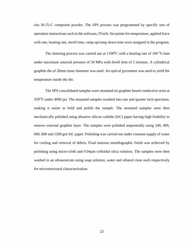
Figure 12: Backscattered images of Ni-5Ti-20C at a) 1KX, b) 10 KX, c) 25KX, d) 50KX
magnification
Figure 12. shows SEM images of SPS processed Ni-5Ti-20C composite. In this micrograph
it can be observed that the volume fraction of TiC precipitates is lower as compared to Ni-
10Ti-10C, Ni-7Ti-20C, and Ni-6Ti-20C. Also, coarser and uniformly distributed graphite
phase within nickel matrix has been clearly seen primarily due to higher atomic percent of
graphite present in these composites.

40
Figure 13: Backscattered images of Ni-4Ti-20C at a) 1KX, b) 10 KX, c) 25KX, d) 50KX
magnification
Figure 13. shows SEM images of SPS processed Ni-4Ti-20C composite. It shows increased
volume fraction of graphite phase with decrease in TiC precipitates as compared to Ni-7Ti-
20C and Ni-6Ti-20C. It can be clearly seen from the micrographs that as the C/Ti ratio
increases, the volume fraction of graphite phase is these composites increases.

41
Figure 14: Backscattered images of Ni-3Ti-20C at a) 1KX, b) 10 KX, c) 25KX, d) 50KX
magnification
Micrographs of Ni-3Ti-20C composites are shown in Figure 14. As compared to
previous Ni-Ti-C composites lowest volume fraction of TiC precipitates were observed in
these Ni-3Ti-20C composites, due to presence of very less at% of titanium available to
react with graphite in order to form in situ TiC precipitates. It is apparent that, the volume
fraction of in situ TiC precipitates decreases and volume fraction of graphite phase in Ni-
Ti-C composites increases as the C/Ti ratio increases.
This microstructural characterization shows that pure nickel exhibits coarser grains
as compared to that of Ni-Ti-C composites, as no second phase precipitates such as TiC

42
and graphite are present to restrict the grain boundaries and limit the grain growth during
sintering. Backscattered micrographs of Ni-Ti-C composites clearly indicate that the
dimension of in situ formed spherical TiC precipitates are in nanosized level and are
uniformly dispersed in the nickel matrix. Crystallite size of TiC precipitates in Ni matrix
remained in nanosized even after SPS processing. The TiC precipitates bordering graphite
phase has also been observed since in situ TiC forms near graphite source due to
availability of carbon in the composition. Additionally, acicular graphite region is also
visible and uniformly distributed within nickel matrix. This is mainly due to unreacted
carbon/graphite left after in situ TiC formation, exhibiting extra/unreacted graphite phase
available in the matrix, which increases the wear resistance of the composite due to inherent
solid lubrication nature of graphite, making it suitable for high temperature surface
engineering application. Also, randomly oriented nickel grains have been observed in all
Ni-Ti-C composites validating the feasibility of mechanical alloying and spark plasma
sintering techniques for processing these in situ metal matrix composites.
4.1.3. Vickers microhardness
Vickers microhardness of SPS processed Ni-Ti-C composites is shown in Figure
15. It is observed that the microhardness drastically increased due to addition of titanium
carbide reinforcement in nickel matrix as compared with pure nickel depicting hardness
value of 147 VHN. It can be attributed to the clean interfacial bond, refined size,
uniformity, and interfacial strength of in situ formed TiC particulates.

43
Figure 15: Vickers microhardness of SPS processed samples
Ni-10Ti-5C exhibited the highest hardness value of 598 VHN. composite, this can
be attributed to presence is mainly due to high volume fraction of TiC reinforcement
present and excess of Titanium in the Nickel matrix. Highest microhardness was expected
in Ni-10Ti-10C as compared to Ni-10Ti-5C, however it exhibited hardness value of 475
VHN which is lower as compared with Ni-10Ti-5C. It may be due to presence of unreacted
graphite which is also seen in the backscattered micrograph of Ni-10Ti-10C.
From Figure 15. it is apparent that the microhardness decreases as C/Ti ratio
increases, which was expected and can be attributed to reduction in the volume fraction of
TiC precipitates and increase in volume fraction of graphite phase in the composite. Ni-
7Ti-20C exhibited hardness value of 318 VHN. However, as the C/Ti ratio increased
further not much variation in microhardness value was observed. This is due to reduction
of titanium content in the composition, resulting in very less in situ TiC formation along
with presence of lubricious graphite phase dispersed throughout the sample.

44
An increase in microhardness clearly indicates pronounced improvement in the
mechanical performance of the composite. This is mainly due to dispersion strengthening,
smaller grain size, and grain boundary strengthening.
Figure 16: Vickers indent impression on a) Ni-10Ti-10C, b) Ni-7Ti-20C, c) Ni-3Ti-20C
Figure 16. shows indent impression of Vickers pyramid on the sample used for the
measurement of the Vickers hardness number. The images were taken at 50X
magnification. Indent on Ni-10Ti-10C has an average diagonal of ~45µm. The average
diagonal size of indent impression on Ni-7Ti-20C was measured as ~54µm. It can be
attributed to presence of hard carbide precipitates present in the sample, acting as a barrier
for indent penetration. The diagonal size of indent impression in graphite rich Ni-3Ti-20C
was found to be ~60µm. This trend clearly indicates that the diagonal size of indent was
found to be increased C/Ti ratio was increased, which resulted in decrease hardness
number. It is observed that microhardness decreases with increase in volume fraction of
soft graphite phase present in the composites. A literature study reveals that this decrease
in microhardness is due to graphite agglomeration.22 However, despite large volume
fraction of graphite phase in Ni-3Ti-20C composite, it still exhibited relatively higher
microhardness or almost twice as that of pure nickel.

45
4.1.4. Tribological test
Ball on disc tribometry tests were performed under a normal load of 100g (1 N)
using a 0.125” Si3N4 ball. Tests were carried out with track radius of ~2.5 mm and at
constant sliding speed of 2.0-2.1 cm/sec. Steady-state friction behavior was observed and
coefficient of friction (CoF) was calculated for a sliding distance of 140m for SPS
processed Ni-10Ti-10C, Ni-5Ti-10C, Ni-7Ti-20C, and Ni-3Ti-20C samples.
Figure 17: Steady state friction of SPS processed samples
Figure 17. shows steady state coefficient of friction (CoF) for SPS processed Ni-
Ti-C composites. Lowest coefficient of friction value of ~0.08 was obtained for Ni-3Ti-
20C. Second lowest CoF value was seen for Ni-10Ti-10C, which was unexpected. But this
resulted mainly due to presence of unreacted graphite phase present in the composite along

46
with TiC precipitates, both beneficial in forming a good lubricious tribofilm on the surface.
Average coefficient of friction value of ~0.09 was seen for Ni-7Ti-20C, which was
expected due to presence of lubricious graphite phase in the composite is beneficial in
reducing the coefficient of friction.
Highest coefficient of friction value of ~0.2 was obtained for Ni-5Ti-10C in
comparison with other samples. This is attributed to low volume fraction of graphite
present in the sample, which is also apparent from the SEM micrographs. Also, it was
observed that coefficient of friction increased at a constant rate over time, exhibiting non
steady state behavior. It may be due to poor adhesion between the phases or large distance
between the graphite phases which prevents the formation of tribofilm on surface of the
sample. Another reason for this unusual behavior can be caused due to severity in the
movement of the pin over wear debris deposited on the sliding track from previous run
leading to asperity on the surface. This causes abrupt increase in temperature at the contact
area which favors the adhesive phenomena, thus increases the coefficient of friction.56

47
4.2. LENSTM processed Ni-Ti-C composites
4.2.1. X-Ray diffraction analysis
Figure 18: XRD pattern for LENSTM processed samples
Figure 18. shows the x-ray diffraction patterns for LENSTM processed Ni-Ti-C. Ni-
10Ti-5C and Ni-10Ti-10C exhibited FCC nickel as well as FCC titanium carbide (TiC)
phases without presence of any HCP graphite peak. This clearly shows that titanium and
graphite has undergone in situ reaction during LENSTM processing forming titanium
carbide (TiC). Peaks corresponding (111), (200), and (220) crystallographic planes of FCC
nickel, whereas peaks corresponding (111), (200), (220) and (311) crystallographic planes

48
of FCC titanium carbide phase were observed at the position which agrees with the X-ray
diffraction data files of pure nickel and TiC.58 Increase in peak intensity of FCC titanium
carbide was observed mainly due to increase in the volume fraction of TiC precipitates
which will be shown in microstructural analysis. No intermetallic phases such as NiTi,
Ni3C were observed. Additionally, peak corresponding to graphite phase is shown in
enlarged view, as it reflected relatively low intensity as compared to other phases. No peak
corresponding to graphite phase was observed in Ni-10Ti-5C and Ni-10Ti-10C, this
indicates that all the carbon present in the composition undergone in situ reaction with
titanium forming TiC precipitates. The HCP (0002) peak reflecting at ~260 was seen only
in Ni-7Ti-20C and Ni-3Ti-20C, which was expected due to excess amount of carbon. Also,
there is an increase in intensity of (0002) carbon peak as the C/Ti ratio increases.

49
4.2.2. Microstructural analysis
SEM images of Ni-10Ti-5C and NI-10Ti-10C is shown in Figure 19. From the
micrograph it is clearly visible that titanium and carbon has undergone in situ reaction
forming TiC precipitates in the nickel matrix. This uniform distribution of the TiC
precipitates can be attributed to the stirring effect produced by the high energy density
beam. Vigorous convection flow due to motion of liquid metal in the melt pool is another
reason for homogeneous distribution of the in situ formed reinforcement precipitates
throughout the microstructure.43,55
Figure 19: Backscattered images of LENSTM processed sample a) Ni-10Ti-5C @ 5KX b)
Ni-10Ti-5C @ 20KX c) Ni-10Ti-10C @ 2KX d) Ni-10Ti-10C @ 20KX

50
Ni-10Ti-5C composite exhibits presence of needle shape TiC precipitates
uniformly distributed in the nickel matrix. These observed TiC precipitates are primarily
eutectic TiC precipitates obtained during solidification of molten Ni-10Ti-5C composites.
Ni-10Ti-10C composite exhibits cuboidal as well as needle shape TiC. Micron sized
cuboidal TiC are primary TiC, whereas fine scaled needle shape TiC are eutectic TiC. In
this Ni-10Ti-10C composites, primary TiC acts as a heterogeneous nucleation sites for
eutectic TiC during solidification.7 Volume fraction of TiC precipitates is more in Ni-10Ti-
10C as compared to Ni-10Ti-5C composites, due to higher at% of carbon present for
titanium to react forming in situ TiC precipitates. A pseudo binary section of ternary Ni-
Ti-C system is shown Figure 20.
Figure 20: Pseudo binary section of ternary Ni-Ti-C system57

51
Figure 21: Ternary phase diagram of Ni-Ti-C system
Figure 21. shows ternary phase diagram of Ni-Ti-C system. It is shown that at
temperature of 27250C both nickel and in situ formed TiC are in liquid phase. During
cooling as the temperature falls below 25000C primary TiC starts forming in the melt pool.
As the temperature falls further below 12800C, the remaining liquid in the melt pool
undergoes pseudo-binary solidification forming eutectic Ni and eutectic TiC. It can be
observed from the SEM images that the primary TiC acts as a nucleation site for the
formation of eutectic TiC. In case of Ni-10Ti-5C where the nickel content is 85%, phase
evolution different than that of Ni-10Ti-10C was observed. In Ni-10Ti-5C only eutectic
TiC was formed on solidification. The pseudo-binary isothermal section of Ni-Ti-C system
shown in Figure 21. helps to understand phase transformation in these Ni-Ti-C composites.

52
Figure 22: Backscattered images of LENSTM processed sample a) Ni-7Ti-20C @ 5KX b)
Ni-7Ti-20C @ 20KX c) Ni-3Ti-20C @ 5KX d) Ni-3Ti-20C @ 30KX
Figure 22. shows backscattered images of Ni-7Ti-20C and Ni-3Ti-20C. In Ni-7Ti-
20C and Ni-3Ti-20C both primary TiC as well as eutectic TiC were observed within the
nickel matrix. It can also be seen that higher volume fraction as well as coarser titanium
carbide precipitates have been observed in Ni-7Ti-20C as compared to Ni-3Ti-20C
composites primarily due to high at% of titanium present for in situ chemical reaction.
Additionally, graphite phase with acicular morphology was also visible in Ni-7Ti-
20C and Ni-3Ti-20C micrographs. High volume fraction of graphite phase has been

53
observed in Ni-3Ti-20C, which is mainly due to low at% of titanium available to react with
carbon. These observations are consistent with what we have seen in x-ray diffraction
analysis. This increased volume fraction of Graphite plays an important role considerably
reducing the coefficient of friction. Also, it was observed that volume fraction and size of
primary TiC are lower in Ni-3Ti-20C as compared to Ni-7Ti-20C.
4.2.3. Vickers microhardness
Figure 23: Vickers microhardness of LENSTM processed samples.
Figure 23. clearly indicates change in the microhardness number, as the function of
increasing C/Ti ratio. The highest microhardness was recorded for Ni-10Ti-10C, its mainly
due to high volume fraction of in situ formed primary as well as eutectic TiC precipitates.
This in situ formed homogeneously dispersed TiC precipitates acts as a barrier for grain
boundary dislocation, therefore the penetration of indent is restricted. Ni-7Ti-20C and Ni-
3Ti-20C exhibit lower microhardness value than Ni-10Ti-10C due to lower volume
fraction of hard TiC precipitates and higher volume fraction of soft graphite phase present.
54
Also, as expected the hardness number for the composite decreased as the C/Ti ratio
increased. This can be attributed to reduction in TiC precipitate, and an increase in graphite
content in the composite. Moreover, standard deviation represented in error bar also shows
that the readings were consistent throughout the sample. This very small variation in
obtained microhardness number clearly indicates the homogeneous dispersion of TiC
phase and graphite phase in the sample, which was also noticed from backscattered
micrographs of the sample.
4.2.4. Tribological test
Tribological test were performed under a normal load of 100g (1 N) using a Si3N4
ball. Test was carried out with track radius of ~2.14 mm and at constant sliding speed of
2.1-2.2 cm/sec. Steady-state friction behavior was observed and coefficient of friction
(CoF) was calculated for a sliding distance of 140m for LENSTM deposited pure Ni, Ni-
10Ti-10C, Ni-10Ti-5C, Ni-7Ti-20C, and Ni-3Ti-20C samples.

55
Figure 24: Steady state friction of LENSTM processed samples
Figure 24. shows steady state coefficient of friction for LENSTM processed Ni-Ti-
C composites. Pure nickel exhibited highest coefficient of friction of ~0.7 as compared
with Ni-TiC-C composites. It was obvious as metallic nickel exhibits adhesive behavior
and has no lubricious friction properties. Lowest value of CoF value of ~0.1 was obtained
for Ni-3Ti-20C, which is mainly due to high volume fraction of graphite phase present in
the composition. Later, it was observed, that the coefficient of friction value increased as
the volume fraction of lubricious graphite present in the sample was reduced.

56
4.2.5 EDS mapping
Figure 25: EDS maps of Ni-10Ti-10C
Figure 25. shows SEM image of LENSTM processed Ni-10Ti-10C its EDS maps of
C, TiC, and Ni. The EDS maps reveal the dispersion of TiC precipitates within the nickel
matrix and is in congruence with the XRD and SEM results. It indicates the presence of
primary TiC and eutectic TiC in the nickel matrix.

57
4.3. SPS process vs LENSTM process
Figure 26: Microhardness comparison between SPS and LENSTM processed samples
Figure 26. shows difference in microhardness of composites of same nominal compositions
but fabricated using two different processing techniques, one using MA followed by SPS
process and other using LENSTM process.
In processing using MA followed by SPS technique, in situ TiC precipitates are formed
due to solid-solid reaction process. In this process it was observed that nanosized TiC
precipitates are formed due to exothermic reaction during MA. Later, the fabrication was
carried out using SPS technique which allowed sintering at relatively lower temperature
below the melting point with shorter sintering time. In this process fabrication is carried
out via solid state reaction which retards the grain growth of nickel. Whereas, in LENSTM
process the in situ reaction take place via solid-liquid reaction. In this reaction, a melt pool

58
is formed at a temperature relatively higher as compared to SPS processing, thus the grain
sizes of nickel as well as in situ formed TiC precipitates are larger. This increased size of
TiC precipitates and nickel grain reduces the hardness of the composites as compared to
SPS processed Ni-Ti-C composites.
It is clearly seen that the composites fabricated using MA and SPS process possess higher
hardness as compared to LENSTM deposited composites. It can be attributed mainly to the
large volume fraction of nanosized and more uniform dispersion of in situ formed TiC
precipitates within the nickel matrix. The reinforcement precipitates formed in LENSTM
processed composite is also uniformly distributed but are coarser as compared to former
process which has also seen in SEM micrographs. It clearly indicates that, the formation of
nanosized in situ reinforcement via MA and the restricted grain growth in SPS process
leads to the high microhardness of the composite.

59
CHAPTER V
CONCLUSION
Fabrication of in situ TiC/C precipitates reinforced in nickel matrix was carried out
successfully using powder metallurgy route by mechanically alloying followed by spark
plasma sintering process and, by metal additive manufacturing technique, i.e. LENSTM
processing technique.
Microstructure evolution and mechanical properties of the processed composites
were investigated successfully via SEM, XRD, Vickers hardness test, and tribological test.
The results indicate that in situ TiC reinforcement in the nickel matrix substantially
increases the hardness of the materials. By altering C/Ti ratio, change in the volume
fraction as well as size of TiC precipitates has been attained and was also able to engineer
an extra graphite phase in these composites, which considerably lowered the coefficient of
friction as compared with pure nickel.
Homogeneous distribution of in situ reinforcement has been achieved using both
the processing routes. In Ni-TiC composites processed via MA followed by SPS technique,
it was observed that the dispersion of in situ formed TiC precipitates within the nickel
matrix was homogeneous and were in nanosized with spherical morphology. It is mainly

60
attributed to mechanical alloying via high energy ball milling followed by spark plasma
sintering. Whereas, two different morphologies of TiC precipitates with size ranging in few
microns have been observed in LENSTM processed composites. The cuboidal shaped
primary TiC acting as a heterogeneous nucleation site for the precipitation of fine needle-
shaped eutectic TiC precipitates during solidification of these Ni-Ti-C composites.
In Ni-Ti-C composites, it was observed that the hardness of the composite increases
as the volume fraction of in situ TiC precipitates increases. The nanosized level of TiC
precipitates attained via MA acts as a pinning point retarding grain growth. Also, the nickel
grain size observed in SPS processed composites was much refined as compared to
LENSTM processed composites. This is mainly due to relatively low processing
temperature and shorter holding time involved in SPS processing technique as compared
to LENSTM processed samples. Therefore, due to a relatively smaller size and more uniform
dispersion of TiC precipitate within the nickel matrix, high microhardness was achieved in
the SPS processed composites in comparison with LENSTM processed counterparts.
Improvement in tribomechanical properties with a reduction in coefficient of
friction was seen in Ni-Ti-C composites. It was seen that the coefficient of friction reduces
as the C/Ti ratio increases. It can be attributed mainly due to increase in the volume fraction
of lubricious graphite phase in these composites.
Therefore, the addition of hard TiC reinforcement and lubricious graphite phase in
the nickel matrix increases hardness and reduces the coefficient of friction making it a
suitable candidate for structural and surface engineering applications.

61
REFERENCES
1. Bakshi, Srinivasa R., Debrupa Lahiri, and Arvind Agarwal. "Carbon nanotube
reinforced metal matrix composites-a review." International materials
reviews 55.1 (2010): 41-64.
2. Ibrahim, I.A., Mohamed, F.A. & Lavernia, E.J. J Mater Sci (1991) 26: 1137-1156.
3. Miracle, D. B. "Metal matrix composites–from science to technological
significance." Composites science and technology 65.15-16 (2005): 2526-2540.
4. Ye, L. L., and M. X. Quan. "Synthesis of nanocrystalline TiC powders by
mechanical alloying." Nanostructured materials5.1 (1995): 25-31.
5. Zhu, Xinkun, et al. "Synthesis of nanocrystalline TiC powder by mechanical
alloying." Materials Science and Engineering: C 16.1-2 (2001): 103-105.
6. Saheb, Nouari, et al. "Spark plasma sintering of metals and metal matrix
nanocomposites: a review." Journal of Nanomaterials 2012 (2012): 18.
7. Borkar, Tushar, et al. "Laser-deposited in situ TiC-reinforced nickel matrix
composites: 3D microstructure and tribological properties." JOM 66.6 (2014): 935-
942.
8. Gopagoni, Sundeep, et al. "Microstructural evolution in laser deposited nickel–
titanium–carbon in situ metal matrix composites." Journal of Alloys and
Compounds 509.4 (2011): 1255-1260.
9. Wang, H., Zhang, S., Zhu, J., Huang, J., Liu, H., & Zhang, H. (2009). In situ TiC-
Reinforced Ni-Based Composite Coating Prepared by Flame Spraying Using
Sucrose as the Source of Carbon. Journal of thermal spray technology, 18(1), 103-
109.

62
10. Guo, Chun, et al. "Effects of WC–Ni content on microstructure and wear resistance
of laser cladding Ni-based alloys coating." Surface and Coatings
Technology 206.8-9 (2012): 2064-2071.
11. Choi, Chul-Jin. "Preparation of ultrafine TiC–Ni cermet powders by mechanical
alloying." Journal of Materials Processing Technology 104.1-2 (2000): 127-132.
12. Tjong, S. C., and Z. Y. Ma. "Microstructural and mechanical characteristics of in
situ metal matrix composites." Materials Science and Engineering: R:
Reports 29.3-4 (2000): 49-113.
13. Suryanarayana, C. "Mechanical alloying and milling." Progress in materials
science 46.1-2 (2001): 1-184.
14. Xiaobo, Zhou Jun Liu Ning Zhang, and Lu Maohua Rong Chunlan. "Effect of
Particle Sizes on Microstructure and Mechanical Properties of Ti (C, N)-based
Cermets [J]." Cemented Carbide 1 (2007).
15. Zheng, Yong, et al. "Effect of nano addition on the microstructures and mechanical
properties of Ti (C, N)-based cermets." Ceramics International 31.1 (2005): 165-
170.
16. Mamedov, V. "Spark plasma sintering as advanced PM sintering method." Powder
Metallurgy 45.4 (2002): 322-328.
17. Viswanathan, Venkatachalapathy, et al. "Challenges and advances in
nanocomposite processing techniques." Materials Science and Engineering: R:
Reports 54.5-6 (2006): 121-285.

63
18. Borkar, Tushar, et al. "Strength versus ductility in carbon nanotube reinforced
nickel matrix nanocomposites." Journal of Materials Research 29.6 (2014): 761-
769.
19. Borkar, Tushar, and Rajarshi Banerjee. "Influence of spark plasma sintering (SPS)
processing parameters on microstructure and mechanical properties of
nickel." Materials Science and Engineering: A 618 (2014): 176-181.
20. Borkar, Tushar, et al. "Excellent strength–ductility combination in nickel-graphite
nanoplatelet (GNP/Ni) nanocomposites." Journal of Alloys and Compounds 646
(2015): 135-144.
21. Munir, Zuhair A., Dat V. Quach, and Manshi Ohyanagi. "Electric current activation
of sintering: a review of the pulsed electric current sintering process." Journal of
the American Ceramic Society 94.1 (2011): 1-19.
22. Sharma, Pardeep, Satpal Sharma, and Dinesh Khanduja. "A study on microstructure
of aluminium matrix composites." Journal of Asian Ceramic Societies 3.3 (2015):
240-244.
23. Gibson, Ian, David W. Rosen, and Brent Stucker. Additive manufacturing
technologies. Vol. 17. New York: Springer, 2014.
24. Morris, David G. "Mechanical behavior of nanostructured materials." Materials
science foundations 2 (1998): 26-84
25. Kaczmar, J., Pietrzak, K., & Wosiski, W. (2000). The production and application
of metal matrix composite materials. Journal of Materials Processing Tech., 106(1
- 3), 58-67.

64
26. Pierson, Hugh O. Handbook of Refractory Carbides & Nitrides: Properties,
Characteristics, Processing and Apps. William Andrew, 1996.
27. Zhuang, Jian, et al. "The influence of technological process on dry sliding wear
behaviour of titanium carbide reinforcement copper matrix composites." Materials
transactions 51.12 (2010): 2311-2317.
28. Upadhyaya, Gopal S. Powder metallurgy technology. Cambridge Int Science
Publishing, 1997.
29. Angelo, P. C., and Ramayyar Subramanian. Powder metallurgy: science,
technology and applications. PHI Learning Pvt. Ltd., 2008
30. Koch, C. C. "Intermetallic matrix composites prepared by mechanical alloying—a
review." Materials Science and Engineering: A 244.1 (1998): 39-48.
31. Whittenberger, J. Daniel, Eduard Arzt, and Michael J. Luton. "Preliminary
investigation of a NiAl composite prepared by cryomilling." Journal of Materials
Research 5.2 (1990): 271-277.
32. Li, Yuxin, et al. "Effect of TiC content on Ni/TiC composites by direct laser
fabrication." Materials & Design 30.4 (2009): 1409-1412.
33. Kumar, K. Ravi, K. Kiran, and V. S. Sreebalaji. "Micro structural characteristics
and mechanical behaviour of aluminium matrix composites reinforced with
titanium carbide." Journal of Alloys and Compounds 723 (2017): 795-801.
34. Zohari, Shokat, et al. "Application of spark plasma sintering (SPS) for the
fabrication of in situ Ni–TiC nanocomposite clad layer." Journal of Alloys and
Compounds 633 (2015): 479-483.

65
35. AlMangour, Bandar, Dariusz Grzesiak, and Jenn-Ming Yang. "In situ formation of
TiC-particle-reinforced stainless steel matrix nanocomposites during ball milling:
Feedstock powder preparation for selective laser melting at various energy
densities." Powder Technology 326 (2018): 467-478.
36. Chawla, Krishan K. "Metal matrix composites." Materials Science and
Technology (2006).
37. Training Sheet and Manual, Optomec Inc., Albuquerque, NM, 2003, pp. 3–4
38. Zheng, B. "Y, Zhou, JE Smugeresky, JM Schoenung, and EJ Lavernia." Metall.
Mater. Trans. A 39 (2008): 2237.
39. B. Zheng, J.E. Smugeresky, Y. Zhou, D. Baker, and E.J. Lavernia: Metall. Mater.
Trans. A, 2008, vol. 39A, pp. 1196–1205
40. Niino M, Hirai T, Watanabe R.J Jpn Soc Comp Mater 1987;13:257–64
41. Kawasaki A, Watanabe R.Ceram Int 1997;23:73–83.
42. Liu, Weiping, and J. N. DuPont. "Fabrication of functionally graded TiC/Ti
composites by laser engineered net shaping." Scripta Materialia 48.9 (2003): 1337-
1342.
43. Zheng, Baolong, et al. "The influence of Ni-coated TiC on laser-deposited IN625
metal matrix composites." Metallurgical and Materials Transactions A 41.3 (2010):
568-573.
44. Y. Xiong, J. E. Smugeresky, L. Ajdelsztajn, Julie M. Schoenung, Mater. Sci. Eng.
A 493 (2008) 261
45. Schwendner, Katrin I., et al. "Direct laser deposition of alloys from elemental
powder blends." Scripta Materialia 45.10 (2001): 1123-1129.

66
46. Kobryn, P. A., and S. L. Semiatin. "Mechanical properties of laser-deposited Ti-
6Al-4V." Solid freeform fabrication proceedings. Austin, 2001.
47. A. Munir, U. Anselmi-Tamburini and M. Ohyanagi, 'The effect of electric field and
pressure on the synthesis and consolidation of materials: A review of the spark
plasma sintering method,' J. Mater. Sci., 41 [3] 763-777 (2006).
48. W. Chen, U. Anselmi-Tamburini, J. E. Garay, J. R. Groza and Z. A. Munir,
'Fundamental investigations on the spark plasma sintering/synthesis process: I.
Effect of dc pulsing on reactivity,' Materials Science and Engineering A, 394 [1-2]
132-138 (2005).
49. X. Song, X. Liu and J. Zhang, 'Neck formation and self-adjusting mechanism of
neck growth of conducting powders in spark plasma sintering,' J Am Ceram Soc,
89 [2] 494-500 (2006).
50. D. Chakravarty, H. Ramesh and T. N. Rao, 'High strength porous alumina by spark
plasma sintering,' Journal of the European Ceramic Society, 29 [8] 1361-1369
(2009).
51. Consolidation and synthesis of materials by electric current activated sintering.
Materials Science and Engineering, 63:127{287, 2009).
52. Tokita, M. "Mechanism of spark plasma sintering." Proc. of the Inter. Sympo. on
Microwave, Plasma and Thermochemical Processing of Advanced
Materials (1997): 69-76.
53. Thermal Technologies, LLC, 1911 Airport Blvd. Santa Rosa, CA. 95403 United
States. Operating and Maintenance Manual, sps 10-3 10 ton edition, 2012.

67
54. Kim, Hoyeol, et al. "Laser engineered net shaping of nickel-based superalloy
Inconel 718 powders onto AISI 4140 alloy steel substrates: Interface bond and
fracture failure mechanism." Materials 10.4 (2017): 341.
55. Modest, M. F., J. Ready, and D. Farson. "Handbook of laser materials processing."
(2001).
56. Salguero, Jorge, et al. "Application of Pin-On-Disc Techniques for the Study of
Tribological Interferences in the Dry Machining of A92024-T3 (Al–Cu)
Alloys." Materials 11.7 (2018): 1236.
57. D. Strzeciwilk, Z. Wokulski, and P. Tkacz, J. Alloy. Compd. 350, 256 (2003)
58. JCPDS card No: 87-0712 and 32-1383
59. Hull, D.; Bacon, D.J. Introduction to Dislocations, 4th ed.; Butterworth Einemann:
Oxford, UK, 2001
60. B.E.Warren. X-Ray Di_raction, chapter 2, page 15. Dover Publications, 31 East
2nd Street, Mineola, NY 11501-3852, 1990
61. Young, Warren Clarence, Richard Gordon Budynas, and Ali M. Sadegh. Roark's
formulas for stress and strain. Vol. 7. New York: McGraw-Hill, 2002.