Compacted exfoliated natural graphite as heat conduction medium
11
Carbon 39 (2001) 2151–2161 Compacted exfoliated natural graphite as heat conduction medium a, b b * M. Bonnissel , L. Luo , D. Tondeur a ´ IMP , UP CNRS 8521, Universite de Perpignan, 52, Avenue de Villeneuve, 66860 Perpignan, France b ´ Laboratoire des Sciences du Genie Chimique, LSGC, CNRS 1, rue Grandville BP 451, 54001 Nancy Cedex, France Received 20 September 2000; accepted 29 January 2001 Abstract Graphite has been used in mixtures with adsorptive or reactive material in order to manufacture compressed blocks with ` ` ´ heat conductive properties [Olives, These de doctorat, Universite de Perpignan, 1999]. In the present work, the intrinsic transfer properties of recompressed exfoliated graphite have been studied. Porous graphite matrices with a bulk density of 50 23 to 1800 kg m were fabricated by one-directional pressing of exfoliated graphite powders, in order to use them as heat conductive media. They were characterized using optical microscopy and helium pycnometry. Gas permeabilities and thermal diffusivities were measured for graphite matrices with different bulk densities. The gas permeability was in the range 211 216 2 of 10 to 10 m . Thermal conductivity values in the axial and the radial directions were in the range 3 to 9 and 3 to 350 21 21 Wm K , respectively. A semi-empirical model was developed to correlate the heat and mass transfer properties of the material with the solid conductivities, bulk density and porosity. 2001 Elsevier Science Ltd. All rights reserved. Keywords: A. Exfoliated graphite; D. Thermal conductivity; Thermal diffusivity; Transport properties 1. Introduction manufacturing. GIC particles are submitted to a short thermal shock, and expand to a small garland looking like Graphite is, like diamond, an allotropic state of carbon. an accordion as shown in Fig. 1a. The volume occupied by Covalent bonds result in carbon atoms being arranged in the garland, and thus the powder apparent density, is ˚ plane sheets according to regular hexagons with 1.42 A linked to the temperature level of the thermal shock (Table side length [1]. The spacing between elemental planes is 1). The NEG type has very little influence on the thermal ˚ properties according to Han [4]. Nevertheless Coudevylle larger (3.35 A), because it is determined by van der [5] notices inferior thermal transfer properties of the G38 Waals-type forces. The difference between bond strength compared to G12 and G3. On the other hand, mass transfer in the two directions is responsible for the anisotropic is better with G12 than with G3 [4,6]. properties of the graphite, including phenomena like Some manufacturers use compacted NEG as high tem- thermal conduction. perature resistant gaskets (PapyexE or GrafoilE). The Due to the weakness of the van der Waals-type forces, it 23 gasket density is about 1100 kg m . is possible to insert various atoms or molecules between The NEG is also used in polymeric resins in order to the planes [2]. Intercalation of various chemical species obtain electrical and mechanical properties (shocks and leads to so-called graphite intercalation compound (GIC). vibrations absorption) [7,8]. GIC particles are about 1 mm diameter and 0.1 mm thick Because of its high porosity (around 84% at 350 kg and are used for their interesting electrical properties [3]. 23 m ) as shown in Fig. 1, and its thermal properties, the Another use of GIC is natural exfoliated graphite (NEG) NEG is used in thermochemical processes to improve thermal transfer in porous media. There are two different ways to use NEG to improve the overall thermal properties of materials: the blend method and the fin method. *Corresponding author. Tel.: 133-4-6855-6855; fax: 133-4- The blend method, developed since 1983 at IMP in 6855-6869. E-mail address: [email protected] (M. Bonnissel). Perpignan [9,10] is based on intimate mixing [5] of the 0008-6223 / 01 / $ – see front matter 2001 Elsevier Science Ltd. All rights reserved. PII: S0008-6223(01)00032-X
Transcript of Compacted exfoliated natural graphite as heat conduction medium
Carbon 39 (2001) 2151–2161
Compacted exfoliated natural graphite as heat conductionmedium
a , b b*M. Bonnissel , L. Luo , D. Tondeura ´IMP, UP CNRS 8521, Universite de Perpignan, 52, Avenue de Villeneuve, 66860 Perpignan, France
b ´Laboratoire des Sciences du Genie Chimique, LSGC, CNRS 1, rue Grandville BP 451, 54001 Nancy Cedex, France
Received 20 September 2000; accepted 29 January 2001
Abstract
Graphite has been used in mixtures with adsorptive or reactive material in order to manufacture compressed blocks with` ` ´heat conductive properties [Olives, These de doctorat, Universite de Perpignan, 1999]. In the present work, the intrinsic
transfer properties of recompressed exfoliated graphite have been studied. Porous graphite matrices with a bulk density of 5023to 1800 kg m were fabricated by one-directional pressing of exfoliated graphite powders, in order to use them as heat
conductive media. They were characterized using optical microscopy and helium pycnometry. Gas permeabilities andthermal diffusivities were measured for graphite matrices with different bulk densities. The gas permeability was in the range
211 216 2of 10 to 10 m . Thermal conductivity values in the axial and the radial directions were in the range 3 to 9 and 3 to 35021 21W m K , respectively. A semi-empirical model was developed to correlate the heat and mass transfer properties of the
material with the solid conductivities, bulk density and porosity. 2001 Elsevier Science Ltd. All rights reserved.
Keywords: A. Exfoliated graphite; D. Thermal conductivity; Thermal diffusivity; Transport properties
1. Introduction manufacturing. GIC particles are submitted to a shortthermal shock, and expand to a small garland looking like
Graphite is, like diamond, an allotropic state of carbon. an accordion as shown in Fig. 1a. The volume occupied byCovalent bonds result in carbon atoms being arranged in the garland, and thus the powder apparent density, is
˚plane sheets according to regular hexagons with 1.42 A linked to the temperature level of the thermal shock (Tableside length [1]. The spacing between elemental planes is 1). The NEG type has very little influence on the thermal
˚ properties according to Han [4]. Nevertheless Coudevyllelarger (3.35 A), because it is determined by van der[5] notices inferior thermal transfer properties of the G38Waals-type forces. The difference between bond strengthcompared to G12 and G3. On the other hand, mass transferin the two directions is responsible for the anisotropicis better with G12 than with G3 [4,6].properties of the graphite, including phenomena like
Some manufacturers use compacted NEG as high tem-thermal conduction.perature resistant gaskets (PapyexE or GrafoilE). TheDue to the weakness of the van der Waals-type forces, it
23gasket density is about 1100 kg m .is possible to insert various atoms or molecules betweenThe NEG is also used in polymeric resins in order tothe planes [2]. Intercalation of various chemical species
obtain electrical and mechanical properties (shocks andleads to so-called graphite intercalation compound (GIC).vibrations absorption) [7,8].GIC particles are about 1 mm diameter and 0.1 mm thick
Because of its high porosity (around 84% at 350 kgand are used for their interesting electrical properties [3].23m ) as shown in Fig. 1, and its thermal properties, theAnother use of GIC is natural exfoliated graphite (NEG)
NEG is used in thermochemical processes to improvethermal transfer in porous media. There are two differentways to use NEG to improve the overall thermal propertiesof materials: the blend method and the fin method.*Corresponding author. Tel.: 133-4-6855-6855; fax: 133-4-
The blend method, developed since 1983 at IMP in6855-6869.E-mail address: [email protected] (M. Bonnissel). Perpignan [9,10] is based on intimate mixing [5] of the
0008-6223/01/$ – see front matter 2001 Elsevier Science Ltd. All rights reserved.PI I : S0008-6223( 01 )00032-X
2152 M. Bonnissel et al. / Carbon 39 (2001) 2151 –2161
Nomenclature
a, b, c, d, e, f empirical constants used in Eqs. (22), (26), (30)21 21c specific heat capacity, J kg Kp
d diameter, mh sample dimension in the compacting direction, mk shape coefficient, –o
2K permeability, mL, l sample dimensions, mm mass of the sample, kgn empirical constant in Eq. (30), –P pressure, PaT tortuosity, –
21u gas velocity, m s3V volume, m
x reduced length, –y abscissa, mZ length of the sample in the flow direction, mGreek letters
2 21a thermal diffusivity, m sd deformation ratio, –´ porosity, –
21 21l thermal conductivity, W m KL overall anisotropy, –m viscosity, Pa s
23r density, kg m
23r uncompacted initial NEG density, kg mo
23r upper density of the isotropic zone, kg m1
23r upper density of the non-oriented graphite planes zone, kg m2
23r maximal density of compact graphite, kg mM
23r overall bulk density, kg mm
u average rotation angle, radSubscriptsc relative to capillary tubef relative to fluidgr relative to graphitem average, bulk
23M maximal, at r 5 2200 kg mM
o initialp porouss relative to solidt overalli parallel to compression direction' perpendicular to compression direction
23NEG powder with the active product (activated carbon (below 400 kg m ) [16–18] but the properties at higher[11], zeolite, metallic salt [12] . . . ). densities are not well known.
The fin method is based on the use of highly conductive The present article presents a model of the variations offins regularly spaced in the porous medium. The fins could the transfer properties (thermal conductivity and per-be made of metal (copper [13,14]) or compacted NEG meability) with the apparent density and experimental[15]. The main drawback of the metallic fins is their measurements, compared to the numerical solution of thechemical sensitivity (copper) and their relatively low model.thermal diffusivity as compared to the thermal diffusivityof graphite.
The NEG densities used in the blend method are in the 2. Samples manufacturing23range of 50 to 400 kg m and in the range of 200 to 2200
23kg m for the fin method. The mass and heat transfer The graphite samples are manufactured by unidirection-properties have been widely studied for low densities ally compacting natural exfoliated graphite (NEG). Initial-
M. Bonnissel et al. / Carbon 39 (2001) 2151 –2161 2153
pressed into consolidated porous graphite matrices. Theinterlocking of the particles produces a cohesive solidwithout a binder. For the present study, small blocks(2532535 mm) and sheets (150355 mm with variousthicknesses) were manufactured.
3. Modeling
The essential points in the present approach are that adensity gradient exists in the sample in the directionparallel to the compression force and that the properties inthe perpendicular direction are different. In the following,several densities are used:
• r is the overall bulk density of the block determinedm
by dividing the mass of the block by its overall volumeVt
m]r 5 . (1)m Vt
• r is the maximal density of the compacted graphite. ItM
is determined by helium pycnometry measurements ofthe total porous volume V of the block. r is given by:p M
m]]r 5 . (2)M V 2Vt p
• r is defined as the upper limit of r below which the1 m
material remains isotropic for heat and mass transfer.
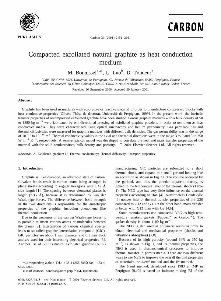
Fig. 1. NEG particle. Electronic microscopy 3150 magnification.We can separate the compression phenomenon into two23Compacted NEG sample with density of 352 kg m . Electronicstages. For low average densities (r , r ) the compres-m 1microscopy 32000 magnification.sion is essentially isotropic. The local bulk density r ishomogeneous and is equal to the overall bulk density r .mly, NEG particles are 0.25 mm in diameter and a fewFor higher overall bulk densities (r . r ) the local bulkm 1millimetre long cylinders as shown in Fig. 1a. Thedensity near the piston head and the bottom die is higher
apparent density of this non-consolidated material is verythan in the middle of the sample as shown in Fig. 2. The23low (about 1.7 kg m ). Expanded graphite powder can be
Table 1aExfoliation temperature and NEG powder densities
Temperature Apparent density Name23(8C) (kg m )
b300 38 G38c500 8.2 EG5c600 5.4 EG6c700 4.9 EG7c800 4.5 EG8d1000 12 G12
b1000 4 G4d1000 3 G3
a 23Non-porous graphite density: 2250 kg m .b IMP-CNRS. Fig. 2. Schematic representation of the compacting process withc Ref. [4]. non-uniform distribution of the local density along the compactingd Le Carbone Lorraine. axis.
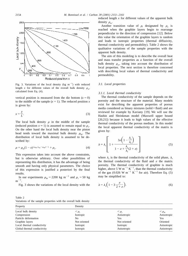
2154 M. Bonnissel et al. / Carbon 39 (2001) 2151 –2161reduced length x for different values of the apparent bulkdensity r .m
Another transition value of r, designated by r is2
reached when the graphite layers begin to rearrangeperpendicular to the direction of compression [12]. Belowthis value the orientation of the graphite layers is randomand leads to isotropic properties (thermal diffusivity,thermal conductivity and permeability). Table 2 shows thequalitative variations of the sample properties with theapparent bulk density.
The aim of this modeling is to describe the overall heatand mass transfer properties as a function of the overallbulk density r , taking into account the distribution ofm
local properties. The next section is therefore concernedwith describing local values of thermal conductivity andpermeability.
23 3.1. Local propertiesFig. 3. Variations of the local density (kg m ) with reducedlength x for different values of the overall bulk density r ,m
calculated from Eq. (4).3.1.1. Local thermal conductivity
The thermal conductivity of the sample depends on thevertical position is measured from the die bottom (x 5 0)porosity and the structure of the material. Many modelsto the middle of the sample (x 5 1). The reduced position xexist for describing the apparent properties of porousis given by:media considered as binary mixtures (solid1fluid) and are
y reviewed for example by Kaviany [19]. We will use the]x 5 . (3)L Hashin and Shrinkman model (Maxwell upper bound
[20,21]) because it leads to high values of the effectiveThe local bulk density r in the middle of the sample thermal conductivity of the porous medium. In this model(reduced position x 5 1) is assumed to remain equal to r .1 the local apparent thermal conductivity of the matrix isOn the other hand the local bulk density near the piston given by:head tends toward the maximal bulk density r . TheM
distribution of local bulk density is assumed to be de- ls]3´ 1 2S Dscribed by: lf
]]]]]l 5 l 1 1 (5)s l( r /r 2r )21 sM m Mr 5 r 1 2 x 1 r . (4)s d 3 4m 1 ]1 2 ´ 1 2 1 ´s dlf
This expression takes into account the above constraints,where l is the thermal conductivity of the solid phase, ls fbut is otherwise arbitrary. Over other possibilities ofthe thermal conductivity of the fluid and ´ the matrixrepresenting this distribution, it has the advantage of beingporosity. The thermal conductivity of graphite is muchsmooth and having only physical parameters. The choice
21 21higher, above 5 W m K , than the thermal conductivityof this expression is justified a posteriori by the final21 21of the gas (0.026 W m K for air). Therefore Eq. (5)results.
23 may be simplified to:In our experiments r 5 2200 kg m and r 5 50 kgM 123m .
´]]Fig. 3 shows the variations of the local density with the l 5 l 1 2 3 . (6)S Ds 2 1 ´
Table 2Variations of the sample properties with the overall bulk density
Property Density
Local bulk density , r , r , r1 2 M
Compression Isotropic Anisotropic AnisotropicParticle deformation No Yes YesGraphite layers Not oriented Not oriented OrientedLocal thermal conductivity Isotropic Isotropic AnisotropicGlobal thermal conductivity Isotropic Anisotropic Anisotropic
M. Bonnissel et al. / Carbon 39 (2001) 2151 –2161 2155
In our case the solid thermal conductivity depends on the The physical interpretation of u is the average angle of thegraphite layers orientation. During compaction, the orienta- graphite planes with the direction of compression. It can betion of the graphite layers induces a local anisotropy. One verified that for r 5 r the value of u is p /4, that is the2
may define a parallel and a perpendicular local thermal average random value of this angle, and for r 5 r , atM
conductivity (relative to the direction of compression) maximal compression, u 5 p /2, that is, all the graphitewhich may be described by: layers are oriented perpendicular to the direction of
compression. Eqs. (7)–(10) are the basic elements of ther]l 5 l f(u ) 1 l 1 2 f(u ) (7)s d present original model.f gsi Mi M' rM The thermal diffusivity is defined by:
r]l 5 l 1 2 f(u ) 1 l f(u ) (8)s d lf gs' Mi M' r ]M a 5 (11)
rcp
where l is the limit parallel thermal conductivity andMi
where c is the specific heat capacity of the graphite. Eq.l the limit perpendicular thermal conductivity as r pM'
(6) allows to evaluate the parallel and perpendiculartends toward r . These two values are unknown and areM
thermal conductivity of the material using l and l forconsidered as parameters and must be adjusted. f(u ) is si s'
l .some weighting function with the following properties: s
• for r # r , f(u ) is constant and equal to 0.5 3.1.2. Local permeability2
• for r $ r , f(u ) increases with r from 0.5 to 1. As in the Carman–Kozeny model [22], the graphite2
matrix porosity is supposed to be composed of a bundle ofcapillary tubes of effective length L . Z where Z is theThe following expressions satisfy these criteria c
thickness of the medium in the direction of flow. Thef(u ) 5 0.5 for r # r2 Hagen–Poiseuille relationship gives a relation between the
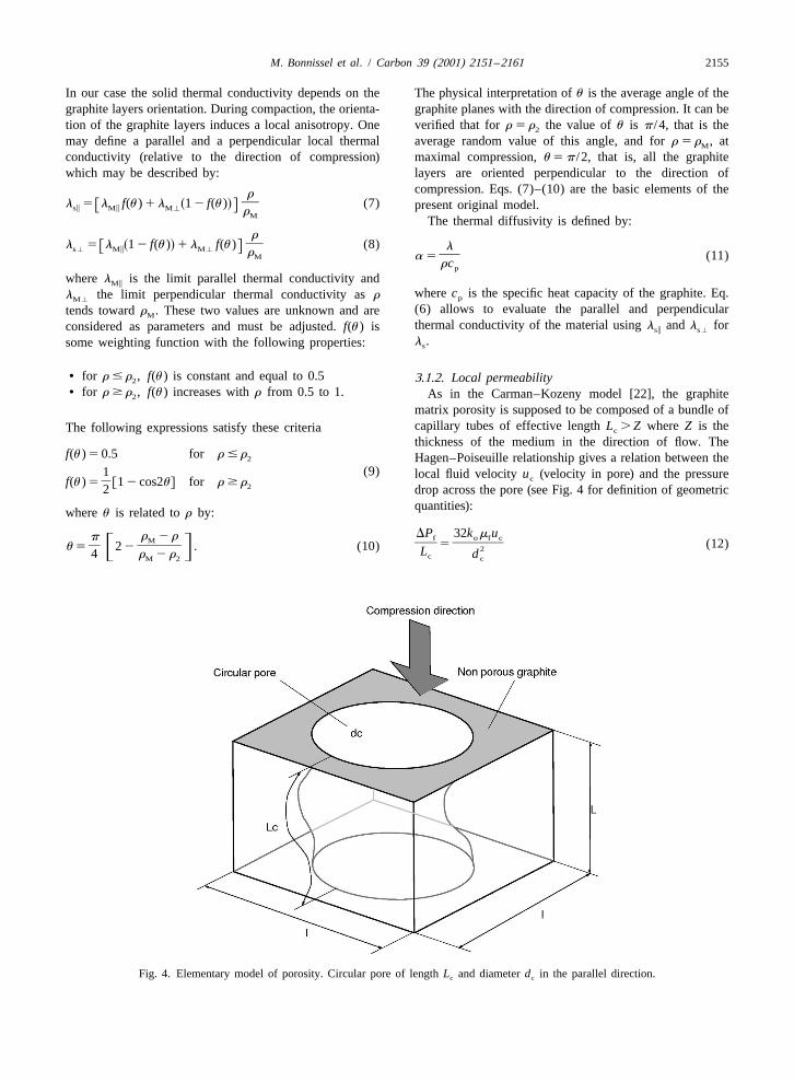
(9)1 local fluid velocity u (velocity in pore) and the pressurec]f(u ) 5 1 2 cos2u for r $ rf g 22 drop across the pore (see Fig. 4 for definition of geometricquantities):where u is related to r by:
DP 32k m ur 2 rp f o f cM ] ]]]5 (12)] ]]u 5 2 2 . (10) 2F G L4 r 2 r dcM 2 c
Fig. 4. Elementary model of porosity. Circular pore of length L and diameter d in the parallel direction.c c
2156 M. Bonnissel et al. / Carbon 39 (2001) 2151 –2161
where k is a shape coefficient for non circular tubes This relation allows to express the pore diameter d as ao c
(k 5 1 for a circular tube). The Darcy law links the function of the ratio r /r . Substituting into Eq. (17) weo M
filtration velocity u (evaluated without porous medium) to get:the pressure drop relative to the medium thickness Z: 2
2r l 1] ]]K 5 1 2 . (21)S Di 3DPK r 8pf TM]]u 5 (13)
m Zf The permeability is proportional to the square of theporosity and inversely proportional to the cube of thewhere K is the permeability.tortuosity. Assuming a linear variation of the tortuosityThe average pore velocity u and the filtration velocity uc
with the bulk density we obtain:are related by:
2rLu c ]1 2]]u 5 . (14) 2 S Dc rl´ Z M]]]]]K 5 (22)i 3r8p
]c 1 dDefining the tortuosity as T 5 L /Z and eliminating the S Dc rMvelocity in Eq. (12) with Eqs. (13) and (14), we obtain thefollowing expression of the matrix permeability K: where c and d are empirical constants.
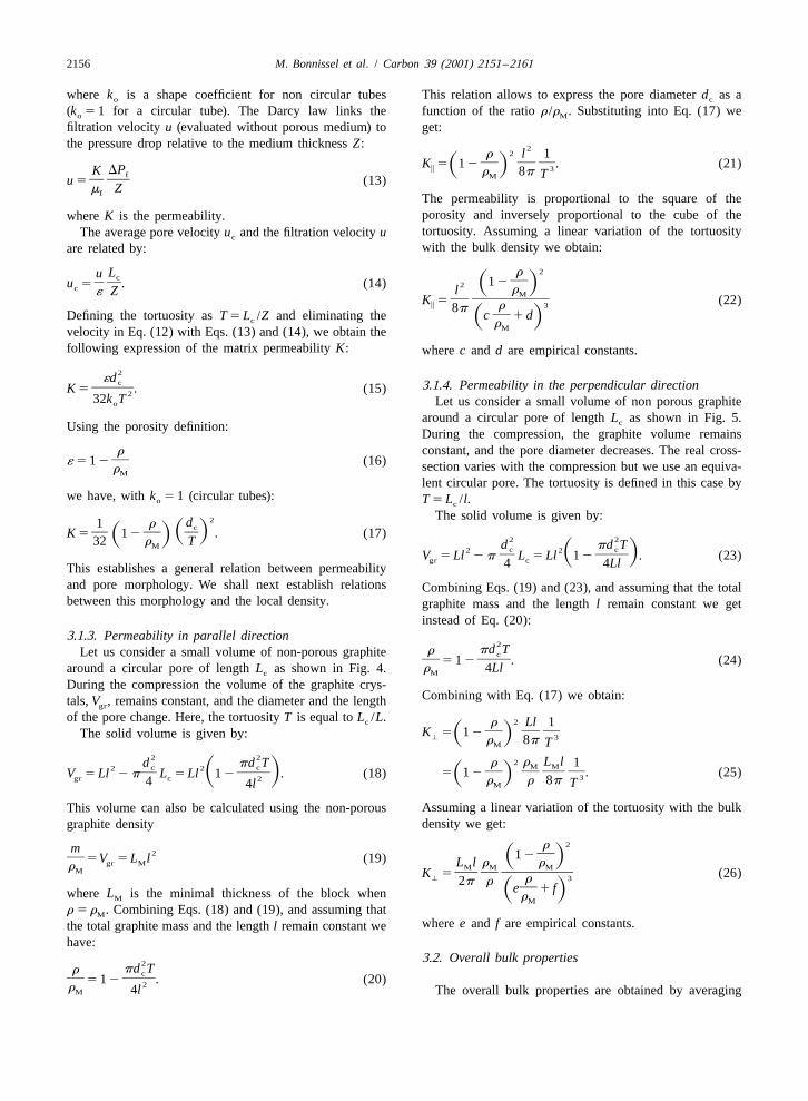
2´d c 3.1.4. Permeability in the perpendicular direction]]K 5 . (15)232k T Let us consider a small volume of non porous graphiteo
around a circular pore of length L as shown in Fig. 5.cUsing the porosity definition: During the compression, the graphite volume remainsconstant, and the pore diameter decreases. The real cross-r
]´ 5 1 2 (16) section varies with the compression but we use an equiva-rM
lent circular pore. The tortuosity is defined in this case bywe have, with k 5 1 (circular tubes):o T 5 L /l.c
The solid volume is given by:2d1 r c] ] ]S DK 5 1 2 . (17)S D 2 232 r TM d pd Tc c2 2S D] ]]V 5 Ll 2 p L 5 Ll 1 2 . (23)gr c4 4LlThis establishes a general relation between permeability
and pore morphology. We shall next establish relations Combining Eqs. (19) and (23), and assuming that the totalbetween this morphology and the local density. graphite mass and the length l remain constant we get
instead of Eq. (20):3.1.3. Permeability in parallel direction
2pd TrLet us consider a small volume of non-porous graphite c
] ]]5 1 2 . (24)r 4Llaround a circular pore of length L as shown in Fig. 4. Mc
During the compression the volume of the graphite crys-Combining with Eq. (17) we obtain:tals, V , remains constant, and the diameter and the lengthgr
of the pore change. Here, the tortuosity T is equal to L /L.c 2r Ll 1] ]]K 5 1 2The solid volume is given by: S D' 3r 8p TM
2 22 r L lr 1d pd T M Mc c2 2 ] ]]]5 1 2 . (25)] ]]V 5 Ll 2 p L 5 Ll 1 2 . (18)S D S D 3gr c 2 r r 8p4 TM4l
Assuming a linear variation of the tortuosity with the bulkThis volume can also be calculated using the non-porousdensity we get:graphite density
2rm 2 ]1 2] S D5V 5 L l (19)gr M L l r rM M MrM ]]]]]]K 5 (26)' 3r2p r]e 1 fS Dwhere L is the minimal thickness of the block when rM M
r 5 r . Combining Eqs. (18) and (19), and assuming thatM
where e and f are empirical constants.the total graphite mass and the length l remain constant wehave:
3.2. Overall bulk properties2pd Tr c
] ]]5 1 2 . (20)2r 4lM The overall bulk properties are obtained by averaging
M. Bonnissel et al. / Carbon 39 (2001) 2151 –2161 2157
Fig. 5. Elementary model of porosity. Circular pore of length L and diameter d in the perpendicular direction.c c
the local property over the whole sample, that is by where r is the initial bulk density for non-compactedo
integrating over the sample thickness, in the direction of graphite powder, and r the measured overall bulk den-m
compression. For example, it is possible to obtain the sity.perpendicular overall bulk permeability using: The a zone corresponds to the particle packing phenom-
enon, where the graphite matrix is isotropic. In the b zone,1
particle deformation occurs, and the graphite matrix be-K̄ 5E K dx (27) comes anisotropic. d follows the empiric expression:' '
0n 1 / nron ]d 5 a ln P 1 b 1 1 1 (30)s dF S D Gwhich expresses the addition of parallel conductances. rM
Similarly, the parallel overall bulk permeability is written:
1
1 1] ]5E dx (28)¯ KK ii 0
which expresses the addition of conductances in series.In these integrations, K is a function of r through Eqs.
(22) and (26), respectively, and r is a function of xthrough Eq. (4).
4. Experiments
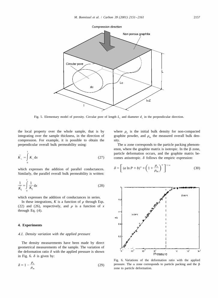
4.1. Density variation with the applied pressure
The density measurements have been made by directgeometrical measurements of the sample. The variation ofthe deformation ratio d with the applied pressure is shownin Fig. 6. d is given by:
Fig. 6. Variations of the deformation ratio with the appliedro pressure. The a zone corresponds to particle packing and the b]d 5 1 2 (29)rm zone to particle deformation.
2158 M. Bonnissel et al. / Carbon 39 (2001) 2151 –2161
23with a 5 0.097; b 5 0.9; n 5 2 17; r 5 1.7 kg m ando23
r 5 2200 kg m .M
Thus combining Eqs. (29) and (30) we obtain arelationship between the overall bulk density r and them
applied pressure to form the matrix. Fig. 7 shows thisrelationship for various values of the initial bulk densityr .o
4.2. Permeability
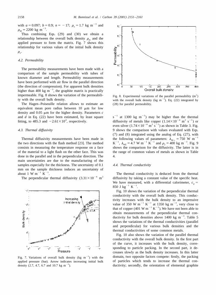
The permeability measurements have been made with acomparison of the sample permeability with tubes ofknown diameter and length. Permeability measurementshave been performed with air flow in the parallel direction(the direction of compression). For apparent bulk densities
23higher than 400 kg m , the graphite matrix is practically2impermeable. Fig. 8 shows the variation of the permeabili- Fig. 8. Experimental variations of the parallel permeability (m )
23ty with the overall bulk density. with the overall bulk density (kg m ). Eq. (22) integrated byThe Hagen–Poiseuille relation allows to estimate an (28) for parallel permeability.
equivalent mean pore radius between 10 mm for lowdensity and 0.05 mm for the higher density. Parameters c
21 23and d in Eq. (22) have been estimated, by least square s at 1300 kg m ) may be higher than the thermal4 24 2 21fitting, to 485.3 and 22.61310 , respectively. diffusivity of metals like copper (1.14310 m s ) or
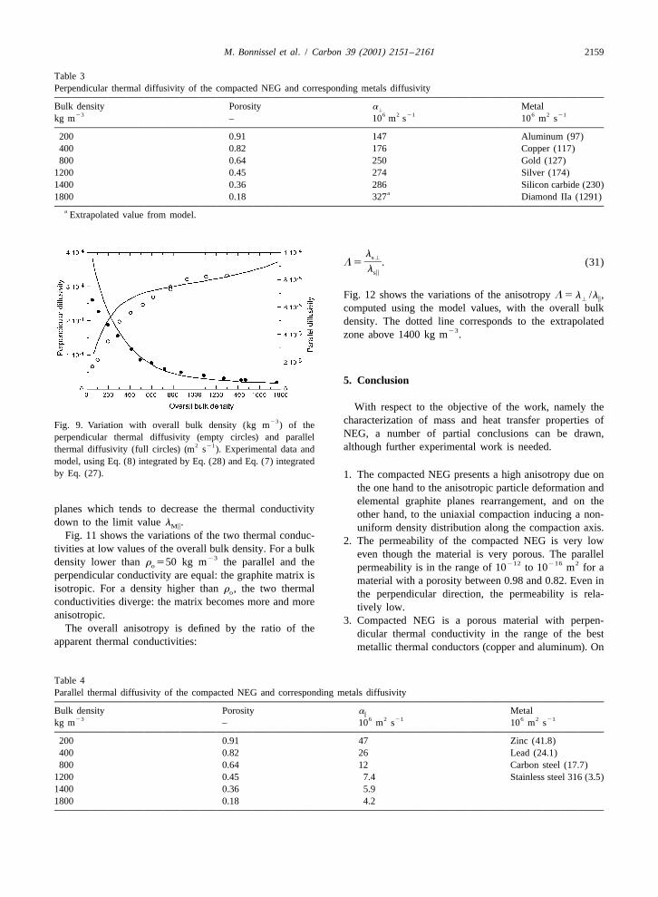
24 2 21even silver (1.74310 m s ) as shown in Table 3. Fig.4.3. Thermal diffusivity 9 shows the comparison with values evaluated with Eqs.
(7) and (8) integrated using the analog of Eq. (27), with21Thermal diffusivity measurements have been made in the following values of parameters: l 5 750 W mM'
21 21 21 23the two directions with the flash method [23]. The method K , l 5 4.7 W m K and r 5 400 kg m . Fig. 9Mi 2
consists in measuring the temperature response on a face shows the comparison for the diffusivity. The latter is inof the material to a light flash on the other face. This was the range of common values of metals as shown in Tabledone in the parallel and in the perpendicular direction. The 4.main uncertainties are due to the manufacturing of thesamples especially for the thickness. The uncertainty of 0.1 4.4. Thermal conductivitymm on the sample thickness induces an uncertainty of
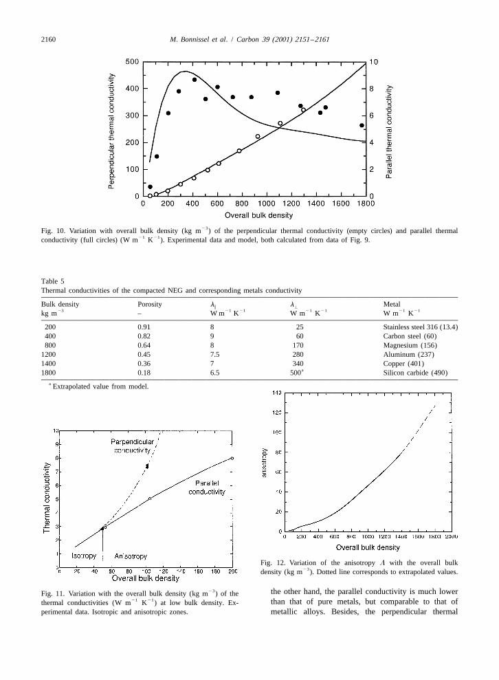
21 21about 1 W m K . The thermal conductivity is deduced from the thermal24 2The perpendicular thermal diffusivity (3.31310 m diffusivity by taking a constant value of the specific heat.
We have measured, with a differential calorimeter, c 5p21 21850 J kg K .
Fig. 10 shows the variation of the perpendicular thermalconductivity with the overall bulk density. This conduc-tivity increases with the bulk density to an impressive
21 21 23value of 350 W m K at 1350 kg m , very close to21 21that of copper (401 W m K ). We have not been able to
obtain measurements of the perpendicular thermal con-23ductivity for bulk densities above 1400 kg m . Table 5
shows the variations of the thermal conductivities (paralleland perpendicular) for various bulk densities and thethermal conductivities of some common metals.
Fig. 10 also shows the variation of the parallel thermalconductivity with the overall bulk density. In the first partof the curve, it increases with the bulk density, corre-sponding to particle packing. In the second part, it de-creases slowly as the bulk density increases. In this latter
23 domain, two opposite factors compete: firstly, the packingFig. 7. Variations of overall bulk density (kg m ) with theof particles which tends to increase the thermal con-applied pressure (bar). Arrow indicates increasing initial bulk
23density (2.7, 4.7, 6.7 and 10.7 kg m ). ductivity; secondly, the orientation of elemental graphite
M. Bonnissel et al. / Carbon 39 (2001) 2151 –2161 2159
Table 3Perpendicular thermal diffusivity of the compacted NEG and corresponding metals diffusivity
Bulk density Porosity a Metal'23 6 2 21 6 2 21kg m – 10 m s 10 m s
200 0.91 147 Aluminum (97)400 0.82 176 Copper (117)800 0.64 250 Gold (127)
1200 0.45 274 Silver (174)1400 0.36 286 Silicon carbide (230)
a1800 0.18 327 Diamond IIa (1291)a Extrapolated value from model.
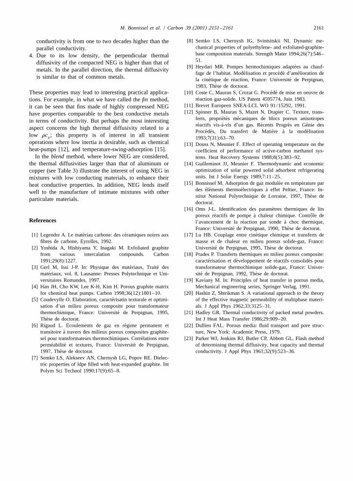
ls']L 5 . (31)lsi
Fig. 12 shows the variations of the anisotropy L 5 l /l ,' i
computed using the model values, with the overall bulkdensity. The dotted line corresponds to the extrapolated
23zone above 1400 kg m .
5. Conclusion
With respect to the objective of the work, namely the23 characterization of mass and heat transfer properties ofFig. 9. Variation with overall bulk density (kg m ) of the
NEG, a number of partial conclusions can be drawn,perpendicular thermal diffusivity (empty circles) and parallel2 21 although further experimental work is needed.thermal diffusivity (full circles) (m s ). Experimental data and
model, using Eq. (8) integrated by Eq. (28) and Eq. (7) integratedby Eq. (27). 1. The compacted NEG presents a high anisotropy due on
the one hand to the anisotropic particle deformation andelemental graphite planes rearrangement, and on the
planes which tends to decrease the thermal conductivity other hand, to the uniaxial compaction inducing a non-down to the limit value l .Mi uniform density distribution along the compaction axis.
Fig. 11 shows the variations of the two thermal conduc- 2. The permeability of the compacted NEG is very lowtivities at low values of the overall bulk density. For a bulk even though the material is very porous. The parallel23density lower than r 550 kg m the parallel and the 212 216 2o permeability is in the range of 10 to 10 m for aperpendicular conductivity are equal: the graphite matrix is material with a porosity between 0.98 and 0.82. Even inisotropic. For a density higher than r , the two thermalo the perpendicular direction, the permeability is rela-conductivities diverge: the matrix becomes more and more tively low.anisotropic. 3. Compacted NEG is a porous material with perpen-
The overall anisotropy is defined by the ratio of the dicular thermal conductivity in the range of the bestapparent thermal conductivities: metallic thermal conductors (copper and aluminum). On
Table 4Parallel thermal diffusivity of the compacted NEG and corresponding metals diffusivity
Bulk density Porosity a Metali23 6 2 21 6 2 21kg m – 10 m s 10 m s
200 0.91 47 Zinc (41.8)400 0.82 26 Lead (24.1)800 0.64 12 Carbon steel (17.7)
1200 0.45 7.4 Stainless steel 316 (3.5)1400 0.36 5.91800 0.18 4.2
2160 M. Bonnissel et al. / Carbon 39 (2001) 2151 –2161
23Fig. 10. Variation with overall bulk density (kg m ) of the perpendicular thermal conductivity (empty circles) and parallel thermal21 21conductivity (full circles) (W m K ). Experimental data and model, both calculated from data of Fig. 9.
Table 5Thermal conductivities of the compacted NEG and corresponding metals conductivity
Bulk density Porosity l l Metali '23 21 21 21 21 21 21kg m – W m K W m K W m K
200 0.91 8 25 Stainless steel 316 (13.4)400 0.82 9 60 Carbon steel (60)800 0.64 8 170 Magnesium (156)
1200 0.45 7.5 280 Aluminum (237)1400 0.36 7 340 Copper (401)
a1800 0.18 6.5 500 Silicon carbide (490)a Extrapolated value from model.
Fig. 12. Variation of the anisotropy L with the overall bulk23density (kg m ). Dotted line corresponds to extrapolated values.
23 the other hand, the parallel conductivity is much lowerFig. 11. Variation with the overall bulk density (kg m ) of the21 21 than that of pure metals, but comparable to that ofthermal conductivities (W m K ) at low bulk density. Ex-
perimental data. Isotropic and anisotropic zones. metallic alloys. Besides, the perpendicular thermal
M. Bonnissel et al. / Carbon 39 (2001) 2151 –2161 2161
[8] Semko LS, Chernysh IG, Svintsitskii NI. Dynamic me-conductivity is from one to two decades higher than thechanical properties of polyethylene- and exfoliated-graphite-parallel conductivity.base composition materials. Strength Mater 1994;26(7):546–4. Due to its low density, the perpendicular thermal51.diffusivity of the compacted NEG is higher than that of
´[9] Heydari MR. Pompes hermochimiques adaptees au chauf-metals. In the parallel direction, the thermal diffusivity´ ´ ´ ´fage de l’habitat. Modelisation et procede d’amelioration de
is similar to that of common metals. ´ ´ ´la cinetique de reaction, France: Universite de Perpignan,`1983, These de doctorat.
´ ´These properties may lead to interesting practical applica- [10] Coste C, Mauran S, Crozat G. Procede de mise en oeuvre de´reaction gaz-solide. US Patent 4595774, Juin 1983.tions. For example, in what we have called the fin method,
[11] Brevet Europeen SNEA-LCL WO 91/15292, 1991.it can be seen that fins made of highly compressed NEG[12] Spinner B, Mauran S, Mazet N, Drapier C. Texture, trans-have properties comparable to the best conductive metals
´ ´ ´ferts, proprietes mecaniques de blocs poreux anisotropesin terms of conductivity. But perhaps the most interesting´ ` ´ ´ ´reactifs vis-a-vis d’un gas. Recents Progres en Genie desaspect concerns the high thermal diffusivity related to a
´ ´ ` ` ´Procedes, Du transfert de Matiere a la modelisationlow rc ; this property is of interest in all transientp 1993;7(31):63–70.operations where low inertia is desirable, such as chemical [13] Douss N, Meunier F. Effect of operating temperature on theheat-pumps [12], and temperature-swing-adsorption [15]. coefficient of performance of active-carbon methanol sys-
In the blend method, where lower NEG are considered, tems. Heat Recovery Systems 1988;8(5):383–92.the thermal diffusivities larger than that of aluminum or [14] Guilleminot JJ, Meunier F. Thermodynamic and economic
optimization of solar powered solid adsorbent refrigeratingcopper (see Table 3) illustrate the interest of using NEG inunits. Int J Solar Energy 1989;7:11–25.mixtures with low conducting materials, to enhance their
´ ´[15] Bonnissel M. Adsorption de gaz modulee en temperature parheat conductive properties. In addition, NEG lends itself´ ´ ´ `des elements thermoelectriques a effet Peltier, France: In-well to the manufacture of intimate mixtures with other
´stitut National Polytechnique de Lorraine, 1997, These departiculate materials.doctorat.
`[16] Oms J-L. Identification des parametres thermiques de lits´ ` ˆporeux reactifs de pompe a chaleur chimique. Controle de
References ´ `l’avancement de la reaction par sonde a choc thermique,´ `France: Universite de Perpignan, 1990, These de doctorat.
´ ´ ´[1] Legendre A. Le materiau carbone: des ceramiques noires aux [17] Lu HB. Couplage entre cinetique chimique et transferts defibres de carbone, Eyrolles, 1992. masse et de chaleur en milieu poreux solide-gaz, France:
´ `[2] Yoshida A, Hishiyama Y, Inagaki M. Exfoliated graphite Universite de Perpignan, 1995, These de doctorat.from various intercalation compounds. Carbon [18] Prades P. Transferts thermiques en milieu poreux composite:
´ ´ ´ ´1991;29(8):1227. caracterisation et developpement de reactifs consolides pour´ ´[3] Gerl M, Issi J-P. In: Physique des materiaux, Traite des transformateur thermochimique solide-gaz, France: Univer-
´ ´ `materiaux, vol. 8, Lausanne: Presses Polytechnique et Uni- site de Perpignan, 1992, These de doctorat.versitaires Romandes, 1997. [19] Kaviany M. In: Principles of heat transfer in porous media,
[4] Han JH, Cho KW, Lee K-H, Kim H. Porous graphite matrix Mechanical engineering series, Springer Verlag, 1991.for chemical heat pumps. Carbon 1998;36(12):1801–10. [20] Hashin Z, Shtrikman S. A variational approach to the theory
´[5] Coudevylle O. Elaboration, caracterisatin texturale et optimi- of the effective magnetic permeability of multiphase materi-sation d’un milieu poreux composite pour transformateur als. J Appl Phys 1962;33:3125–31.
´thermochimique, France: Universite de Perpignan, 1995, [21] Hadley GR. Thermal conductivity of packed metal powders.`These de doctorat. Int J Heat Mass Transfer 1986;29:909–20.
´[6] Rigaud L. Ecoulements de gaz en regime permanent et [22] Dullien FAL. Porous media: fluid transport and pore struc-`transitoire a travers des milieux poreux composites graphite- ture, New York: Academic Press, 1979.
´sel pour transformateurs thermochimiques. Correlations entre [23] Parker WJ, Jenkins RJ, Butler CP, Abbott GL. Flash method´ ´ ´permeabilite et textures, France: Universite de Perpignan, of determining thermal diffusivity, heat capacity and thermal
`1997, These de doctorat. conductivity. J Appl Phys 1961;32(9):523–36.[7] Semko LS, Alekseev AN, Chernysh LG, Popov RE. Dielec-
tric properties of ldpe filled with heat-expanded graphite. IntPolym Sci Technol 1990;17(9):65–8.