Steady-state and non-steady state operation of counter-current chromatography devices
Upload
khangminh22Category
view
1download
0
1
Chapter 3Chapter 3
2
OneOne--Dimensional, SteadyDimensional, Steady--State ConductionState Conduction
Objectives:1. To determine expressions for the temperature distribution and heat
transfer rate in common (planar, cylindrical, and spherical) geometries.
2. To introduce the concept of thermal resistance and to show how thermal circuit may be used to model heat flow.
3
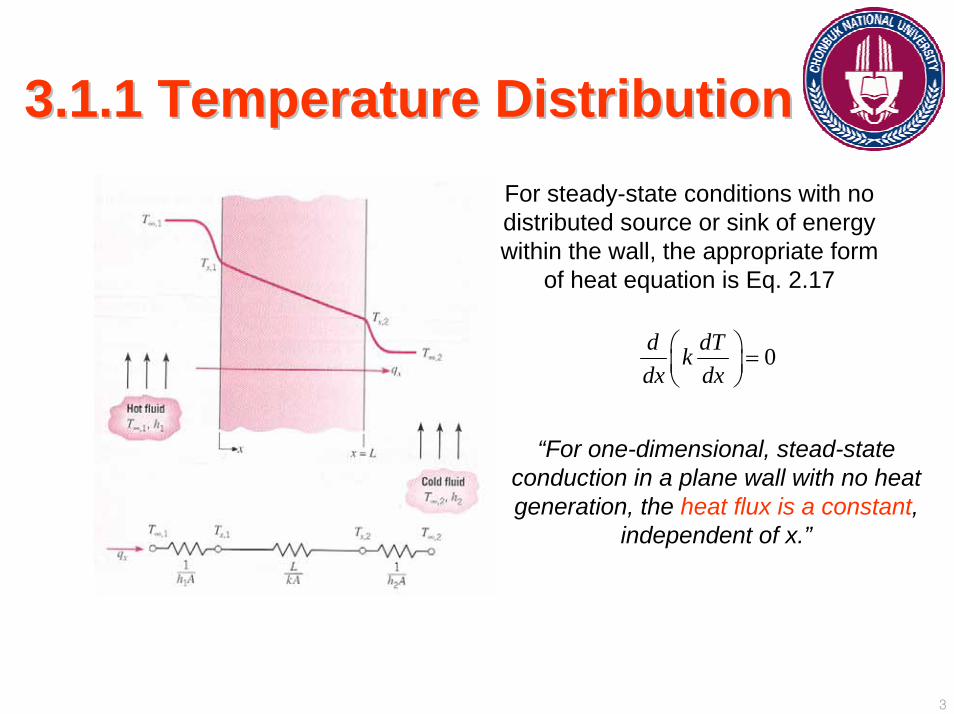
3.1.1 Temperature Distribution3.1.1 Temperature DistributionFor steady-state conditions with no distributed source or sink of energy within the wall, the appropriate form
of heat equation is Eq. 2.17
0d dTkdx dx
⎛ ⎞ =⎜ ⎟⎝ ⎠
“For one-dimensional, stead-state conduction in a plane wall with no heat generation, the heat flux is a constant,
independent of x.”
4
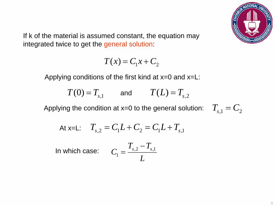
If k of the material is assumed constant, the equation may integrated twice to get the general solution:
1 2( )T x C x C= +
,1(0) sT T= ,2( ) sT L T=
Applying conditions of the first kind at x=0 and x=L:
and
Applying the condition at x=0 to the general solution: ,1 2sT C=
,2 1 2 1 ,1s sT C L C C L T= + = +At x=L:
,2 ,11
s sT TC
L−
=In which case:
5
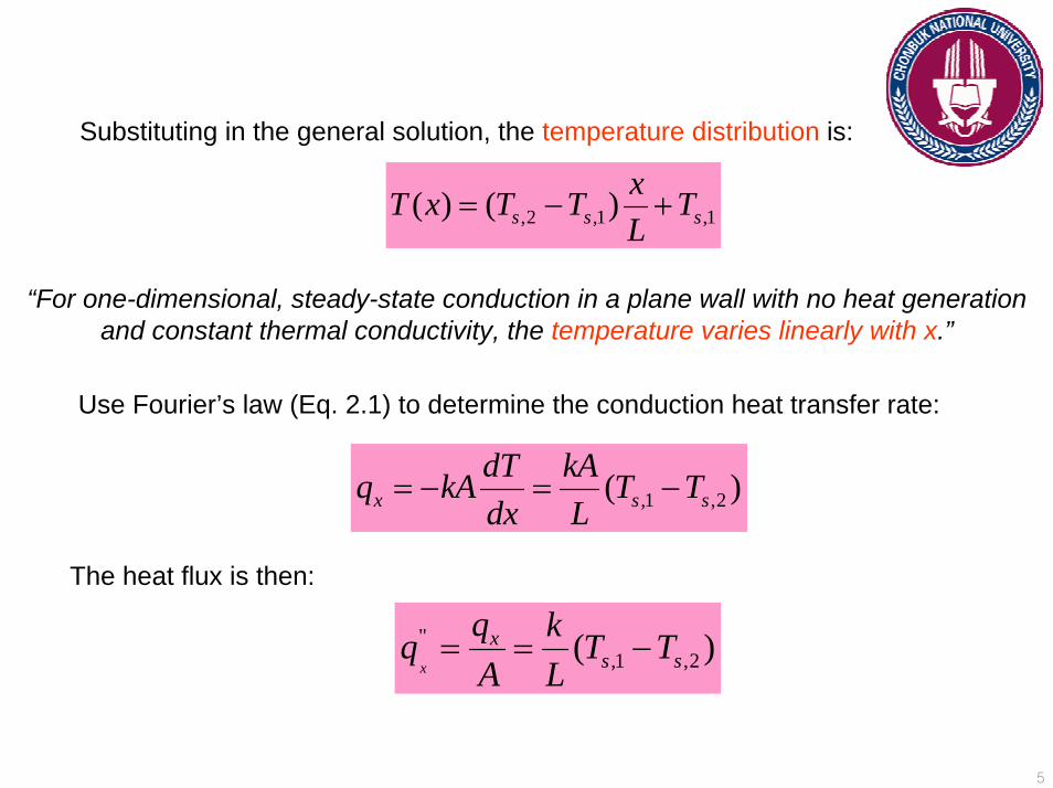
,2 ,1 ,1( ) ( )s s sxT x T T TL
= − +
Substituting in the general solution, the temperature distribution is:
“For one-dimensional, steady-state conduction in a plane wall with no heat generation and constant thermal conductivity, the temperature varies linearly with x.”
,1 ,2( )x s sdT kAq kA T Tdx L
= − = −
",1 ,2( )
x
xs s
q kq T TA L
= = −
Use Fourier’s law (Eq. 2.1) to determine the conduction heat transfer rate:
The heat flux is then:
6
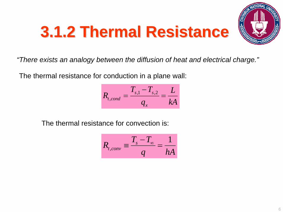
3.1.2 Thermal Resistance3.1.2 Thermal Resistance“There exists an analogy between the diffusion of heat and electrical charge.”
The thermal resistance for conduction in a plane wall:
,1 ,2,
s st cond
x
T T LRq kA−
= =
The thermal resistance for convection is:
,1s
t convT TR
q hA∞−
≡ =
7
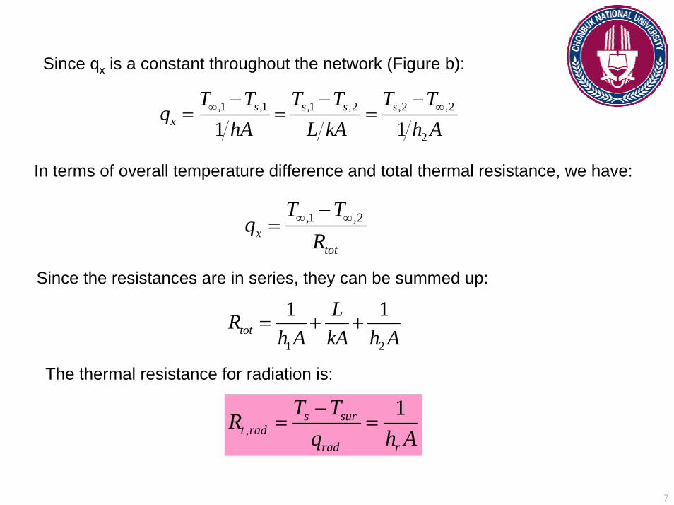
Since qx is a constant throughout the network (Figure b):
,1 ,1 ,1 ,2 ,2 ,2
21 1s s s s
x
T T T T T Tq
hA L kA h A∞ ∞− − −
= = =
In terms of overall temperature difference and total thermal resistance, we have:
,1 ,2x
tot
T Tq
R∞ ∞−
=
1 2
1 1tot
LRh A kA h A
= + +
Since the resistances are in series, they can be summed up:
The thermal resistance for radiation is:
,1s sur
t radrad r
T TRq h A−
= =
8
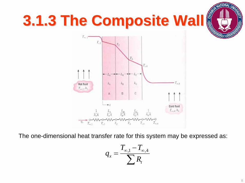
3.1.3 The Composite Wall3.1.3 The Composite Wall
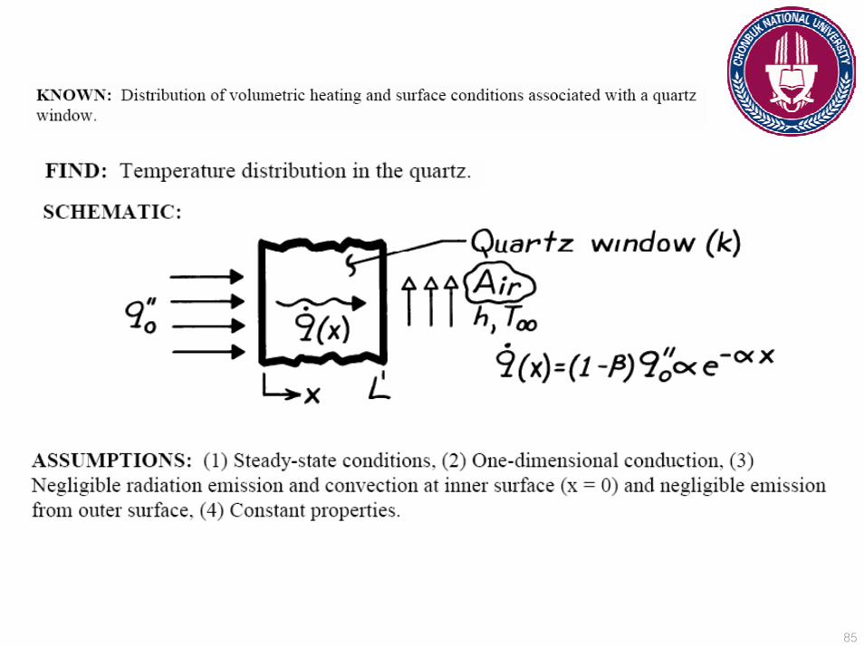
The one-dimensional heat transfer rate for this system may be expressed as:
,1 ,4x
t
T Tq
R∞ ∞−
=∑
9
[ ],1 ,4
1 4(1 ) ( ) ( ) ( ) (1 )xA A B B C C
T Tq
h A L k A L k A L k A h A∞ ∞−
=+ + + +
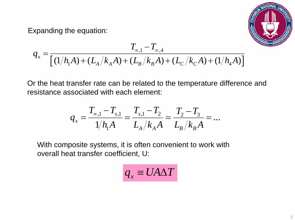
Expanding the equation:
Or the heat transfer rate can be related to the temperature difference and resistance associated with each element:
,1 ,1 ,1 2 2 3
1
...1
s sx
A A B B
T T T T T Tqh A L k A L k A
∞ − − −= = = =
With composite systems, it is often convenient to work with overall heat transfer coefficient, U:
xq UA T≡ ∆
10
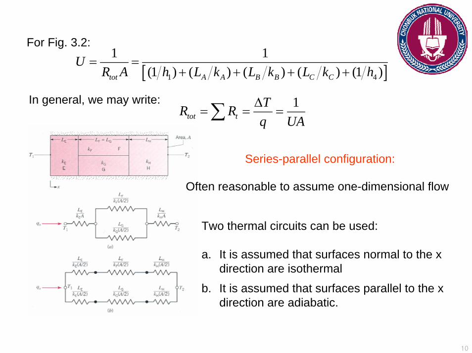
For Fig. 3.2:
[ ]1 4
1 1(1 ) ( ) ( ) ( ) (1 )tot A A B B C C
UR A h L k L k L k h
= =+ + + +
In general, we may write: 1tot t
TR Rq UA∆
= = =∑
Series-parallel configuration:
Often reasonable to assume one-dimensional flow
Two thermal circuits can be used:
a. It is assumed that surfaces normal to the x direction are isothermal
b. It is assumed that surfaces parallel to the x direction are adiabatic.
11
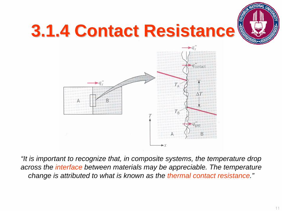
3.1.4 Contact Resistance3.1.4 Contact Resistance
“It is important to recognize that, in composite systems, the temperature drop across the interface between materials may be appreciable. The temperature
change is attributed to what is known as the thermal contact resistance.”

12
For a unit area of the interface, the resistance is defined as:
,
""t c
x
A BT TRq−
=
The existence of a finite contact resistance is due principally to surface roughness effects.
Heat transfer is due to:
1. conduction across the actual contact area2. conduction and/or radiation across the gaps.
The contact resistance may be viewed as two parallel resistances:
1. that due to the contact spots2. that due to gaps
13
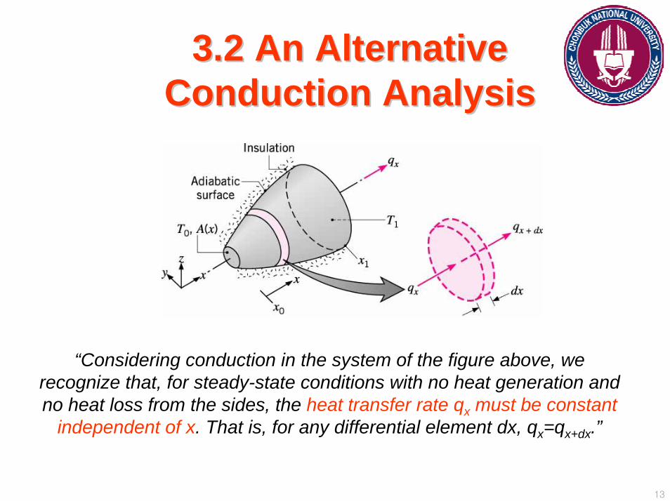
3.2 An Alternative 3.2 An Alternative Conduction AnalysisConduction Analysis
“Considering conduction in the system of the figure above, we recognize that, for steady-state conditions with no heat generation and no heat loss from the sides, the heat transfer rate qx must be constant
independent of x. That is, for any differential element dx, qx=qx+dx.”

14
Since the conduction rate is constant, the rate equation may be integrated,even though neither the rate nor the temperature distribution is known.
Fourier’s law in integral form:
0 0
( )( )
x T
x x T
dxq k TA x
=∫ ∫
xq x k TA∆
= − ∆
If the area A is uniform and k is independent of temperature, Eq. 3.21 reduces to:
Eq. 3.21
Limiting Condition:
Steady-state, one-dimensional transfer with no heat generation.

15
3.3. Radial Systems3.3. Radial Systems“ Cylindrical and spherical systems often experience temperature gradients in the
radial direction only and may therefore be treated as one dimensional.”
3.3.1 The Cylinder3.3.1 The Cylinder

16
1 0d dTkrr dr dr
⎛ ⎞ =⎜ ⎟⎝ ⎠
(2 )rdT dTq kA k rLdr dr
π= − = −
For steady-state condition with no heat generation (from Eq. 2.20):
The rate at which energy is conducted across any cylindrical surface in the solid:
Eq. 3.23
Eq. 3.24
“Heat transfer rate qr (not the heat flux qr”) is a constant in the radial direction.”
17
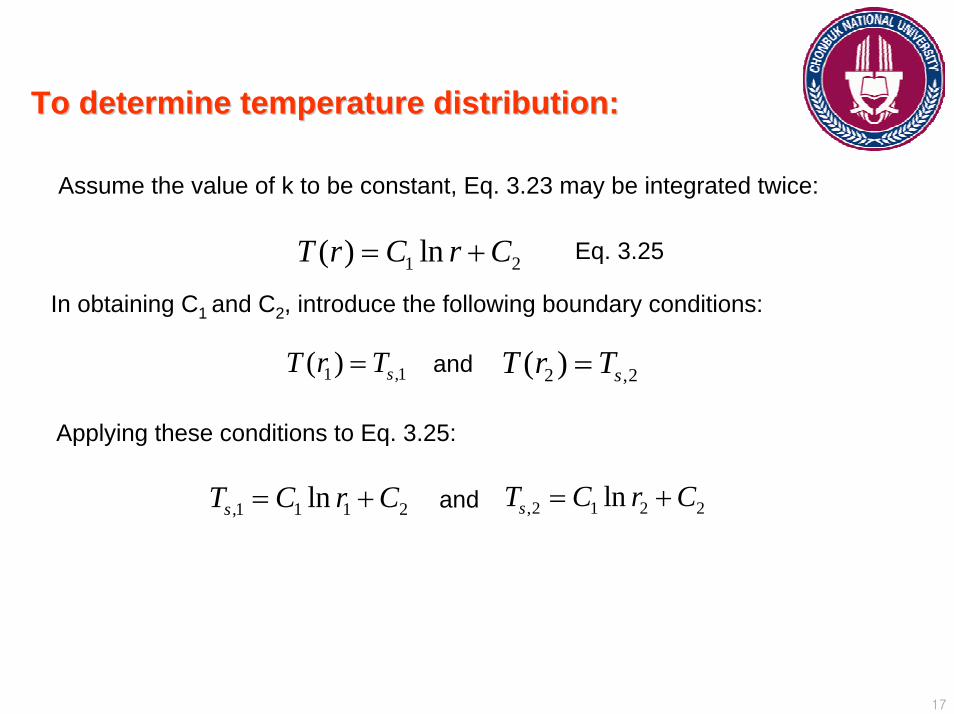
1 2( ) lnT r C r C= +
To determine temperature distribution:To determine temperature distribution:
Assume the value of k to be constant, Eq. 3.23 may be integrated twice:
In obtaining C1 and C2, introduce the following boundary conditions:
1 ,1( ) sT r T= 2 ,2( ) sT r T=
,1 1 1 2lnsT C r C= + ,2 1 2 2lnsT C r C= +
and
Eq. 3.25
Applying these conditions to Eq. 3.25:
and

18
,1 ,2
2 1
2 ( )ln( )
s sr
Lk T Tq
r rπ −
=
2 1,
ln( )2t cond
r rRLkπ
=
,1 ,2,2
1 2 2
( ) lnln( )
s ss
T T rT r Tr r r− ⎛ ⎞
= +⎜ ⎟⎝ ⎠
Solving for C1 and C2 and applying to Eq. 3.25:
“Temperature distribution associated with radial conduction through a cylindrical wall is logarithmic, not linear.”
If Eq. 3.26 is now used with Eq. 3.24, we have:
From this, we can clearly see the thermal resistance for radial conduction in cylindrical wall:
19
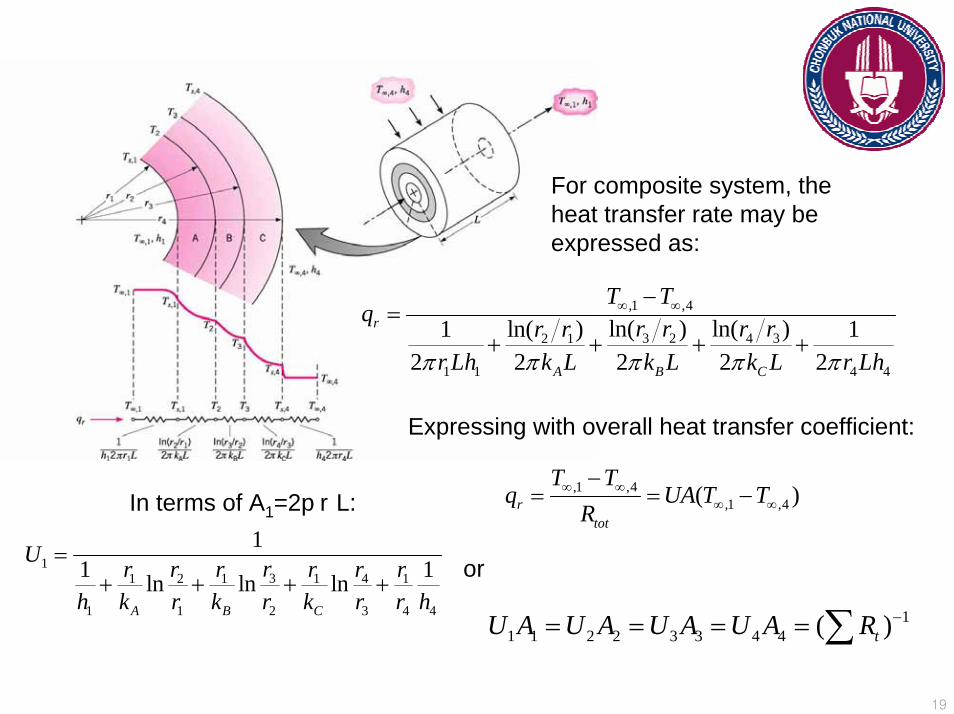
131 2 1 1 4 1
1 1 2 3 4 4
11 1ln ln ln
A B C
U rr r r r r rh k r k r k r r h
=+ + + +
11 1 2 2 3 3 4 4 ( )tU A U A U A U A R −= = = = ∑
,1 ,4,1 ,4( )r
tot
T Tq UA T T
R∞ ∞
∞ ∞
−= = −
For composite system, the heat transfer rate may be expressed as:
,1 ,4
3 2 4 32 1
1 1 4 4
ln( ) ln( )ln( )1 12 2 2 2 2
r
A B C
T Tq r r r rr r
r Lh k L k L k L r Lhπ π π π π
∞ ∞−=
+ + + +
Expressing with overall heat transfer coefficient:
In terms of A1=2prL:
or

20
3.3.2 The Sphere3.3.2 The Sphere
2(4 )rdT dTq kA k rdr dr
π= − = −
The appropriate form of Fourier’s Law is:
Eq. 3.33
2
1
,2
,12 ( )
4s
s
r Trr T
q dr k T dTrπ
= −∫ ∫
Since qr is constant, independent of r, Eq. 3.33 may be expressed in integral form as:
Eq. 3.34
Assuming constant k:
,1 ,2
1 2
4 ( )(1 ) (1 )
s sr
k T Tq
r rπ −
=−
The thermal resistance is:
,1 2
1 1 14t condR
k r rπ⎛ ⎞
= −⎜ ⎟⎝ ⎠
21
3.5 Conduction with Thermal 3.5 Conduction with Thermal Energy GenerationEnergy Generation
“Considering the additional effect on the temperature distribution of processes that may be occurring within the medium. In particular, the thermal energy that is being generated due to conversion from some other energy form.”
A common energy process involves the conversion from electrical to thermal energy in a current-carrying medium.
22
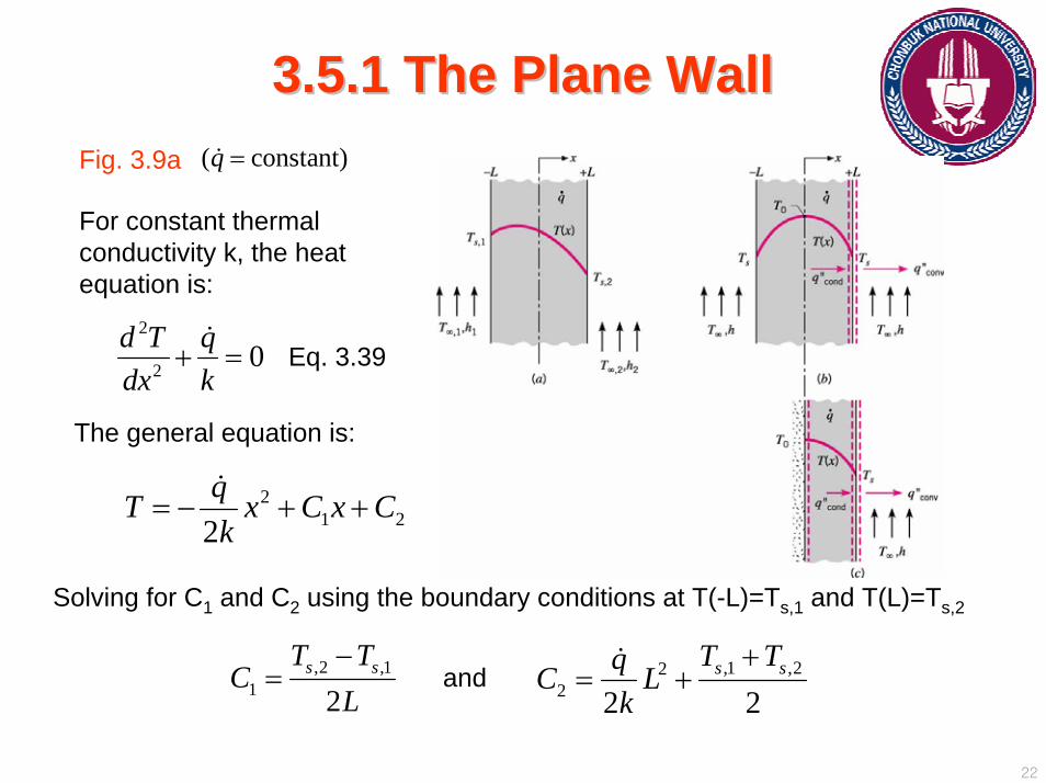
3.5.1 The Plane Wall3.5.1 The Plane Wall
2
2 0d T qdx k
+ =
21 22
qT x C x Ck
= − + +
Fig. 3.9a ( constant)q =
For constant thermal conductivity k, the heat equation is:
Eq. 3.39
The general equation is:
Solving for C1 and C2 using the boundary conditions at T(-L)=Ts,1 and T(L)=Ts,2
,2 ,11 2
s sT TC
L−
= and ,1 ,222 2 2
s sT TqC Lk
+= +
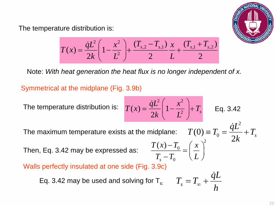
23
2 2,2 ,1 ,1 ,2
2
( ) ( )( ) 1
2 2 2s s s sT T T TqL x xT x
k L L− +⎛ ⎞
= − + +⎜ ⎟⎝ ⎠
The temperature distribution is:
Note: With heat generation the heat flux is no longer independent of x.
Symmetrical at the midplane (Fig. 3.9b)
The temperature distribution is:2 2
2( ) 12 sqL xT x T
k L⎛ ⎞
= − +⎜ ⎟⎝ ⎠
The maximum temperature exists at the midplane:2
0(0)2 sqLT T T
k≡ = +
Eq. 3.42
20
0
( )
s
T x T xT T L
− ⎛ ⎞= ⎜ ⎟− ⎝ ⎠Then, Eq. 3.42 may be expressed as:
sqLT Th∞= +
Walls perfectly insulated at one side (Fig. 3.9c)
Eq. 3.42 may be used and solving for Ts:
24
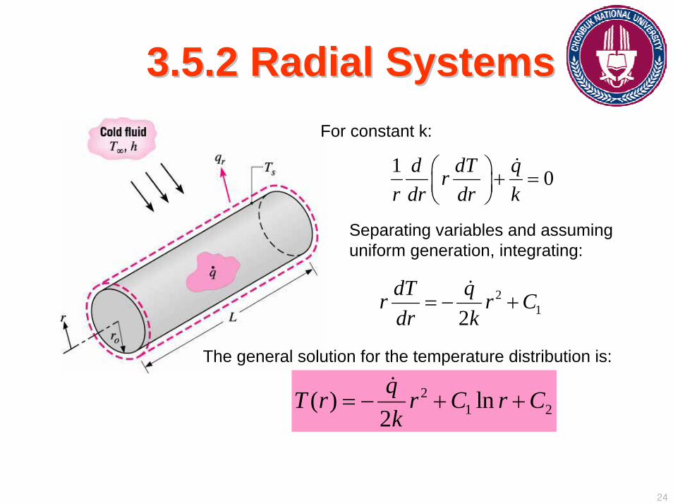
3.5.2 Radial Systems3.5.2 Radial SystemsFor constant k:
1 0d dT qrr dr dr k
⎛ ⎞ + =⎜ ⎟⎝ ⎠
Separating variables and assuming uniform generation, integrating:
212
dT qr r Cdr k
= − +
21 2( ) ln
2qT r r C r Ck
= − + +
The general solution for the temperature distribution is:
25
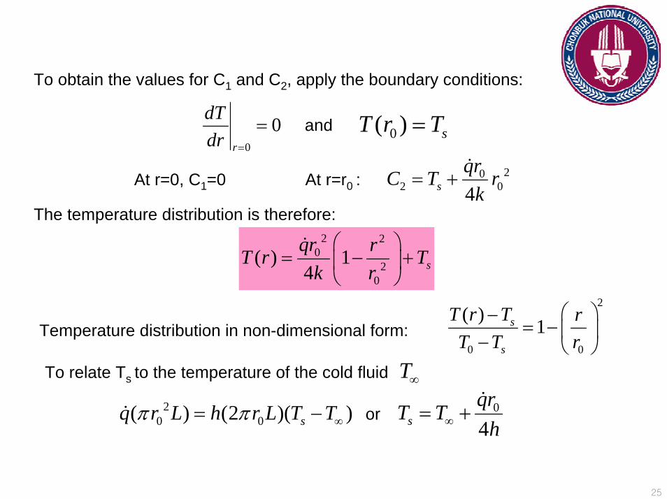
To obtain the values for C1 and C2, apply the boundary conditions:
0
0r
dTdr =
= 0( ) sT r T=and
At r=0, C1=0 202 04s
qrC T rk
= +At r=r0 :
The temperature distribution is therefore:2 2
02
0
( ) 14 sqr rT r T
k r⎛ ⎞
= − +⎜ ⎟⎝ ⎠
Temperature distribution in non-dimensional form:
2
0 0
( ) 1s
s
T r T rT T r
⎛ ⎞−= − ⎜ ⎟− ⎝ ⎠
To relate Ts to the temperature of the cold fluid T∞
20 0( ) (2 )( )sq r L h r L T Tπ π ∞= − 0
4sqrT T
h∞= +or
26
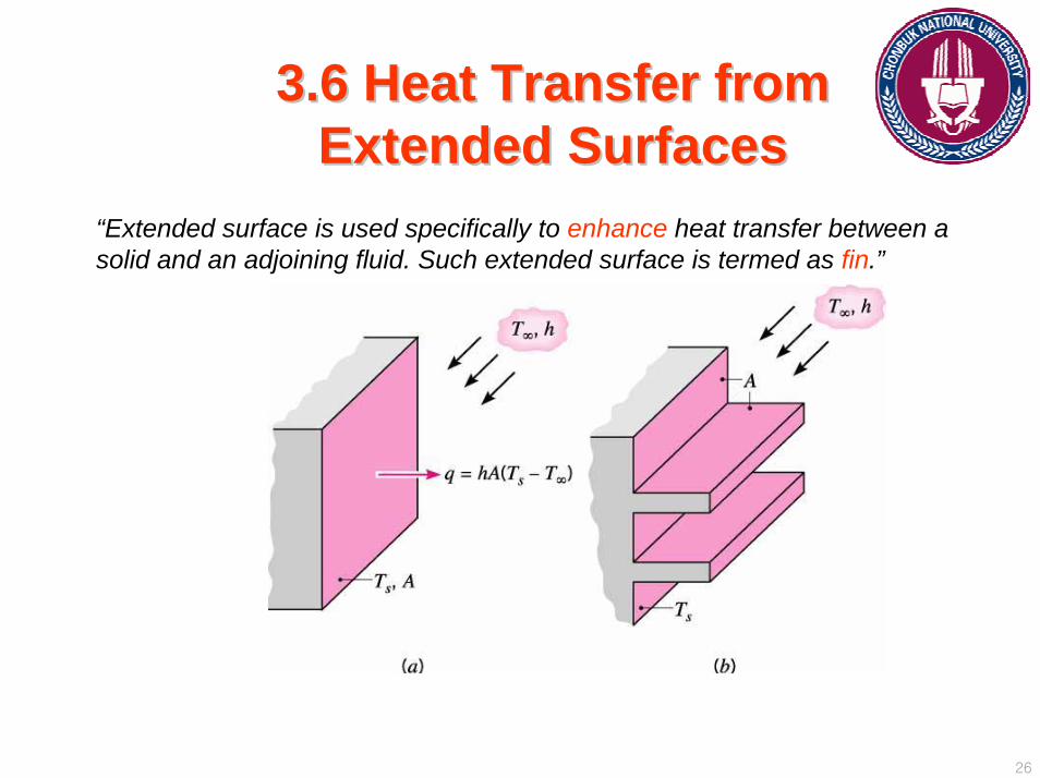
3.6 Heat Transfer from 3.6 Heat Transfer from Extended SurfacesExtended Surfaces
“Extended surface is used specifically to enhance heat transfer between a solid and an adjoining fluid. Such extended surface is termed as fin.”
27
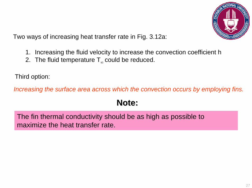
Two ways of increasing heat transfer rate in Fig. 3.12a:
1. Increasing the fluid velocity to increase the convection coefficient h2. The fluid temperature T∞ could be reduced.
Third option:
Increasing the surface area across which the convection occurs by employing fins.
The fin thermal conductivity should be as high as possible to maximize the heat transfer rate.
Note: Note:
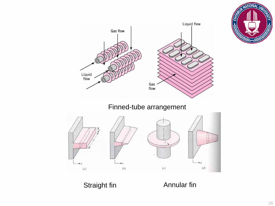
28
Straight fin Annular fin
Finned-tube arrangement
29
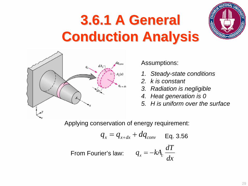
3.6.1 A General 3.6.1 A General Conduction AnalysisConduction Analysis
x x dx convq q dq+= +Applying conservation of energy requirement:
Assumptions:
1. Steady-state conditions2. k is constant3. Radiation is negligible4. Heat generation is 05. H is uniform over the surface
Eq. 3.56
From Fourier’s law: x cdTq kAdx
= −
30
Since the conduction heat rate at x+dx may be expressed as:
xx dx x
dqq q dxdx+ = +
Then: x dx c cdT d dTq kA k A dxdx dx dx+
⎛ ⎞= − − ⎜ ⎟⎝ ⎠
The convection heat transfer rate may be expressed as:
( )conv sdq hdA T T∞= −
Substituting to Eq. 3.56, we have: ( ) 0sc
dAd dT hA T Tdx dx k dx ∞
⎛ ⎞ − − =⎜ ⎟⎝ ⎠
2
2
1 1 ( ) 0c s
c c
dA dAd T dT h T Tdx A dx dx A k dx ∞
⎛ ⎞ ⎛ ⎞+ − − =⎜ ⎟ ⎜ ⎟⎝ ⎠ ⎝ ⎠
or
31
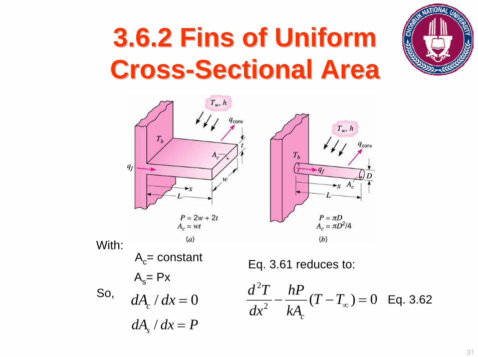
3.6.2 Fins of Uniform 3.6.2 Fins of Uniform CrossCross--Sectional AreaSectional Area
Ac= constant
As= Px2
2 ( ) 0c
d T hP T Tdx kA ∞− − =/ 0cdA dx =
/sdA dx P=
With:Eq. 3.61 reduces to:
So, Eq. 3.62
32
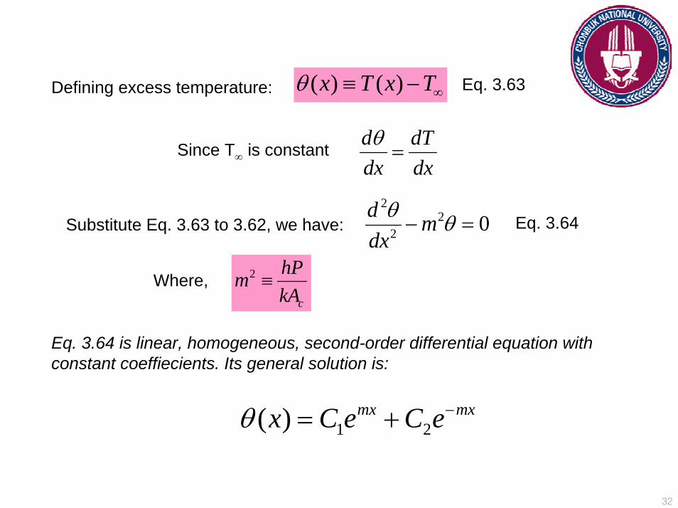
Defining excess temperature: ( ) ( )x T x Tθ ∞≡ −
d dTdx dxθ=Since T∞ is constant
Eq. 3.63
Substitute Eq. 3.63 to 3.62, we have:2
22 0d m
dxθ θ− =
Where, 2
c
hPmkA
≡
Eq. 3.64
Eq. 3.64 is linear, homogeneous, second-order differential equation with constant coeffiecients. Its general solution is:
1 2( ) mx mxx C e C eθ −= +
33
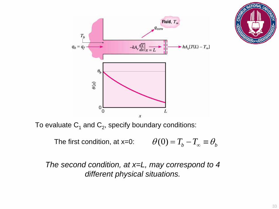
To evaluate C1 and C2, specify boundary conditions:
(0) b bT Tθ θ∞= − ≡The first condition, at x=0:
The second condition, at x=L, may correspond to 4 different physical situations.

34
35
3.6.3 Fin Performance3.6.3 Fin Performance
1. Fin effectiveness:
The ratio of the fin heat transfer rate to the heat transfer rate that would exist without the fin.
,
ff
c b b
qhA
εθ
=
2fε ≥The use of fins may be justified when:
For the infinite fin approximation (case D):
1/ 2
fc
kPhA
ε⎛ ⎞
= ⎜ ⎟⎝ ⎠
Eq. 3.82
Measures of fin thermal performance
36
From Eq. 3.82, important trends may be inferred:
A. Fin effectiveness is enhanced by:
1. Choice of a material of high thermal conductivity (aluminum and copper).2. Increasing the ratio of the perimeter to the cross-sectional area (thin and
closely spaced).
B. Use of fins is better justified with small convection coefficient h (need for fins is stronger if the fluid is gas and by free convection).
37
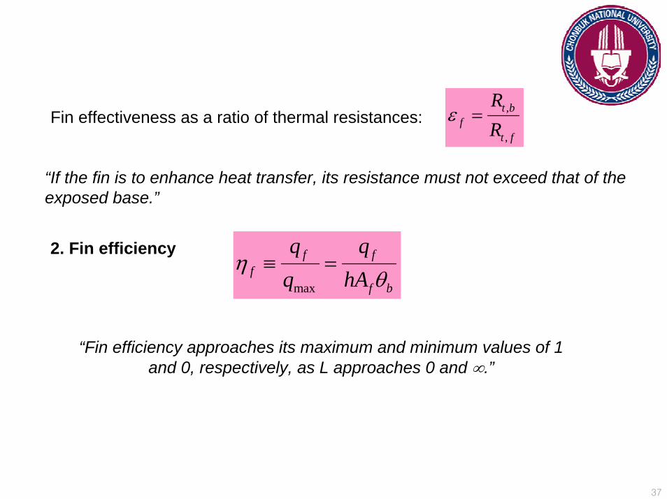
Fin effectiveness as a ratio of thermal resistances:,
,
t bf
t f
RR
ε =
“If the fin is to enhance heat transfer, its resistance must not exceed that of the exposed base.”
2. Fin efficiency
max
f ff
f b
q qq hA
ηθ
≡ =
“Fin efficiency approaches its maximum and minimum values of 1 and 0, respectively, as L approaches 0 and ∞.”
38
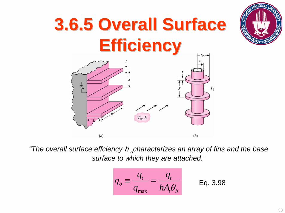
3.6.5 Overall Surface 3.6.5 Overall Surface EfficiencyEfficiency
“The overall surface effciency hocharacterizes an array of fins and the base surface to which they are attached.”
max
t to
t b
q qq hA
ηθ
≡ = Eq. 3.98
39
Exposed portion of the base = prime surface
The total surface area is, t f bA NA A= +
“The maximum possible heat rate would result if the entire fin surface, as well as the exposed base, were maintained at Tb.”
t f f b b bq N hA hAη θ θ= +
[ ( )] 1 (1 )ft f f t f b t f b
t
NAq h N A A NA hA
Aη θ η θ
⎡ ⎤= + − = − −⎢ ⎥
⎣ ⎦
1 (1 )fo f
t
NAA
η η= − −
The total rate of heat transfer by convection from the fins and the prime (unfinned) surface is:
Hence,
Substituting Eq. 3.101 to 3.98, we have:
Eq. 3.101
40
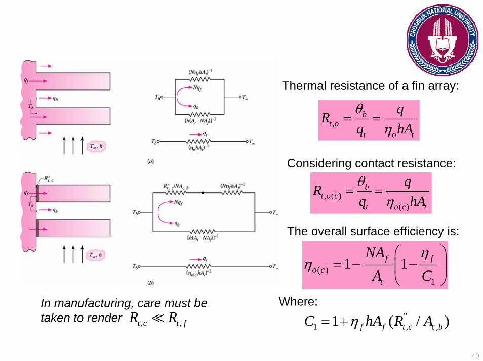
,b
t ot o t
qRq hAθ
η= =
, ( )( )
bt o c
t o c t
qRq hAθ
η= =
( )1
1 1f fo c
t
NAA C
ηη
⎛ ⎞= − −⎜ ⎟
⎝ ⎠
"1 , ,1 ( / )f f t c c bC hA R Aη= +, ,t c t fR R
Thermal resistance of a fin array:
Considering contact resistance:
The overall surface efficiency is:
Where:In manufacturing, care must be taken to render
41
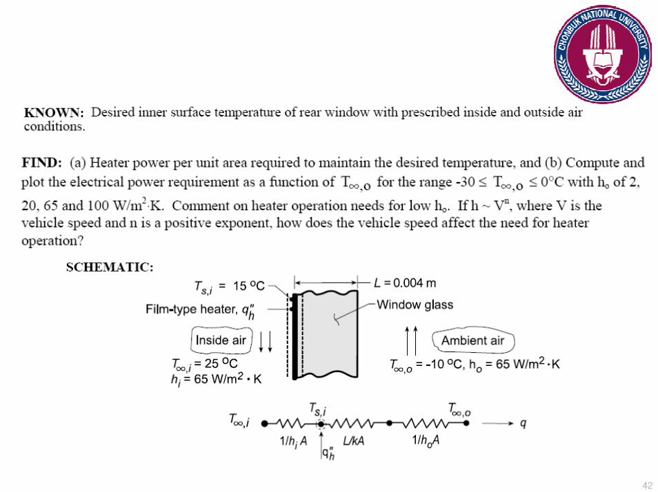
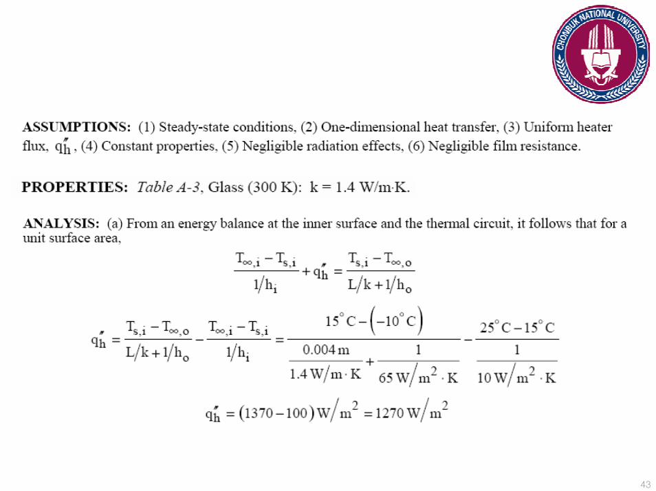
Problem 3.3Problem 3.3The rear window of an automobile is defogged by attaching a thin, transparent,
film-type heating element to its inner surface. By electrically heating this element, a uniform heat flux may be established at the inner surface.
a) For a 4-mm thick window glass, determine the electrical power required per unit window area to maintain an inner surface temperature of 15oC when the interior air temperature and convection coefficient are T∞,i=25oC and hi= 10 W/m2K, while the exterior (ambient) air temperature and convection coefficient are T∞,o= -10oC and ho= 65 W/m2K.
b) In practice T∞,o and ho vary according to weather conditions and car speed. For values of ho=2, 20, 65, and 100 W/m2K, determine and plot the electrical power requirements as a function of T∞,o for -30< T∞,o<0oC. From your results, what can you conclude about the need for heater operation at low values of ho? How is this conclusion affected by the value of T∞,o ? If h Vn, where V is the vehicle speed and n is a positive exponent, how does the vehicle speed affect the need for heater operation?
∝
42
43

44

45
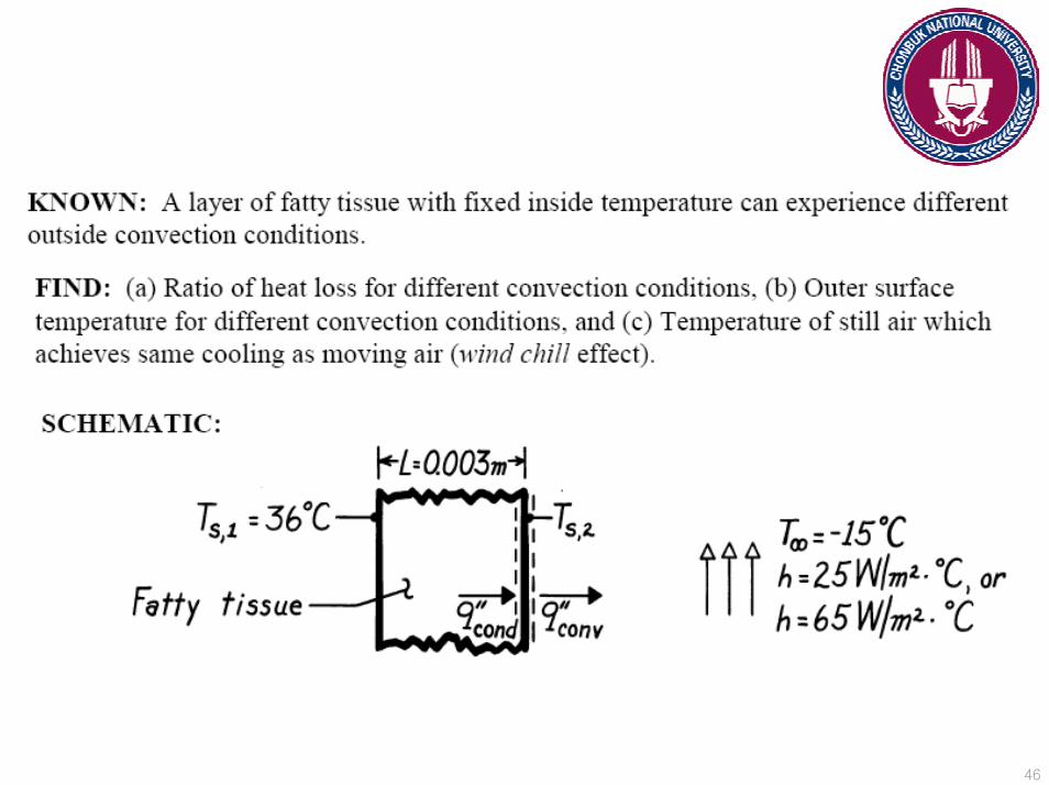
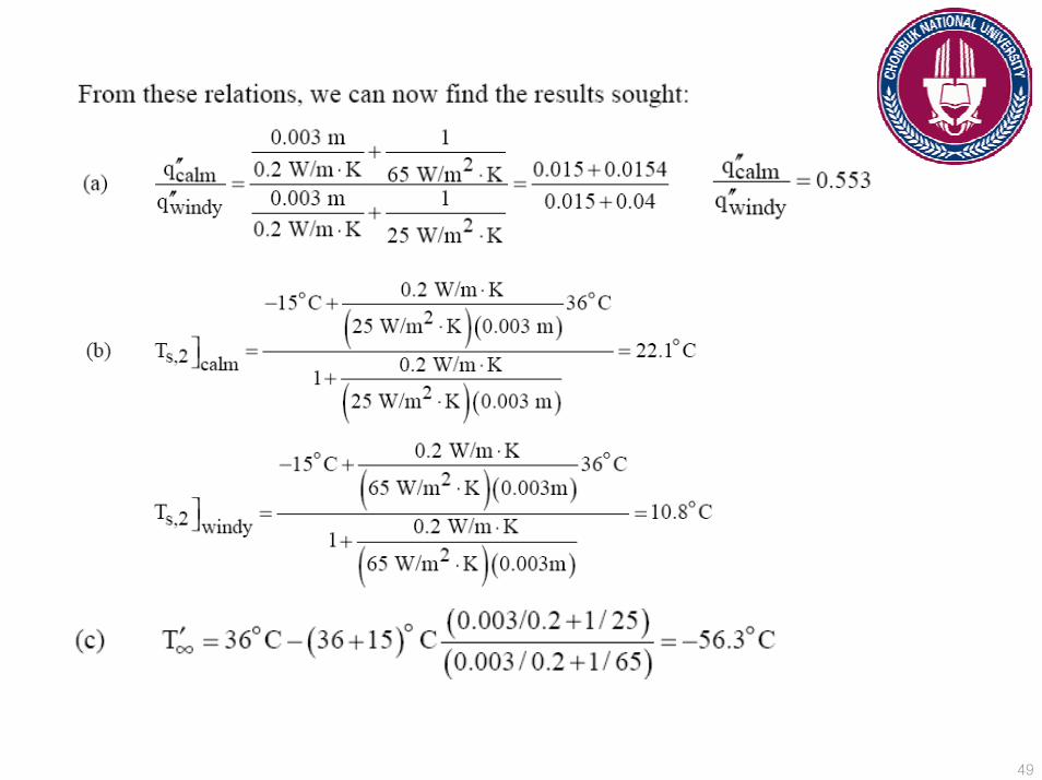
Problem 3.7Problem 3.7The wind chill which is experienced on a cold, windy day, is related to increased
heat transfer from exposed human skin to the surrounding atmosphere. Consider a layer of fatty tissue that is 3 mm thick and whose interior surface is maintained at a temperature of 36oC. On a calm day the convection heat transfer coefficient at the outer surface is 25 W/m2K, but with 30 km/h winds it reaches 65 W/m2K. In both cases the ambient air temperature is -15oC.
a) What is the ratio of the heat loss per unit area from the skin for the calm day to that for the windy day?
b) What will be the skin outer surface temperature for the calm day? For the windy day?
c) What temperature would the air have to assume on the calm day to produce that same heat loss occurring with the air temperature at -15oC on the windy day?
46

47

48
49

50
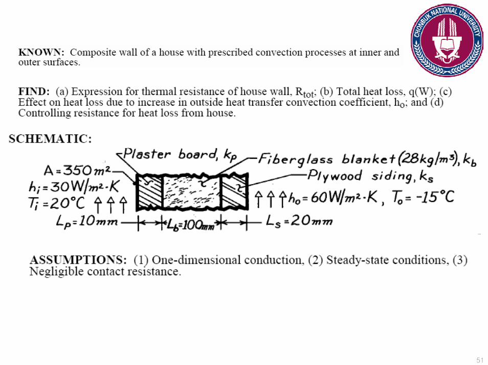
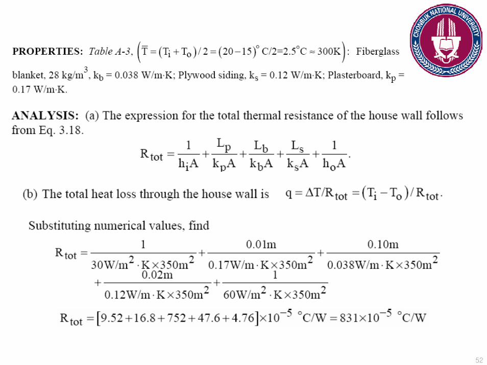
Problem 3.13Problem 3.13A house has a composite wall of wood, fiberglass insulation, and plaster board,
as indicated in the sketch. On a cold winter day the convection heat transfer coefficients are ho= 60 W/m2K and h2= 30 W/m2K. The total wall surface area is 350 m2.
a) Determine a symbolic expression for the total thermal resistance of the wall, including inside and outside convection effects for the prescribed conditions.
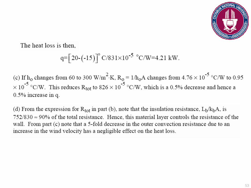
b) Determine the total heat loss through the wall.c) If the wind were blowing violently, raising ho to 300 W/m2K, determine the
percentage increase in the heat loss.d) What is the controlling resistance that determines the amount of heat flow
through the wall?
51
52
53
54
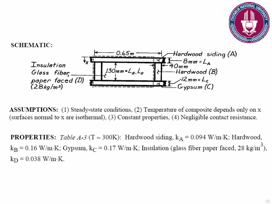
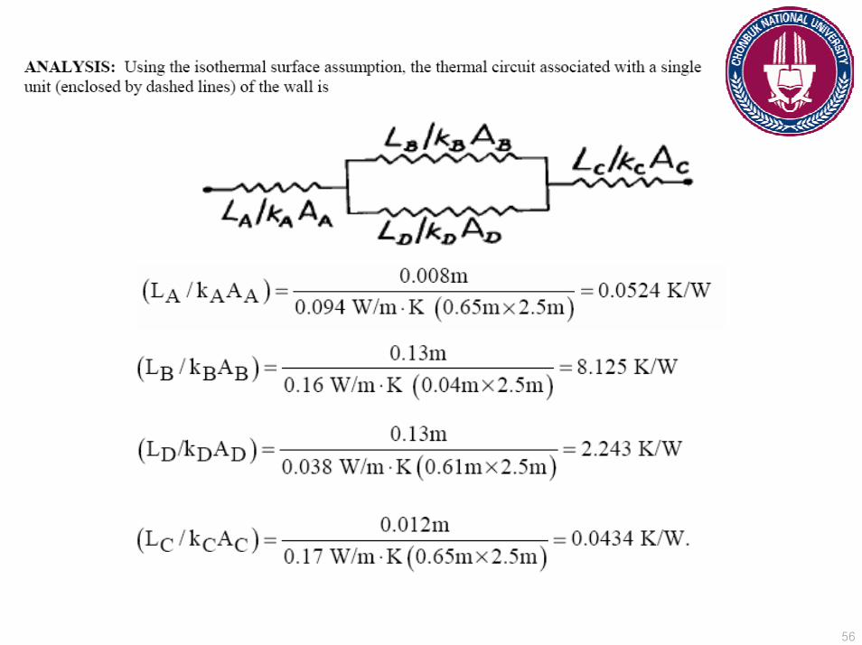
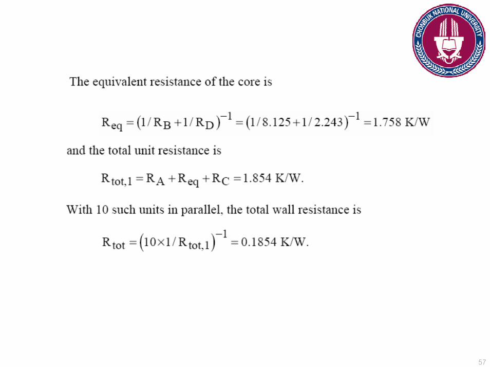
Problem 3.15Problem 3.15Consider a composite wall that includes an 8-mm-thick hardwood siding, 40-mm by 130-mm hardwood studs on 0.65-m centers with glass fiber insulation (paper faced, 28 kg/m3), and a 12-mm layer of gypsum (vermiculite) wall board.What is the thermal resistance associated with a wall that is 2.5 m high by 6.5 m wide (having 10 studs, each 2.5 m high)?
55
56
57
58
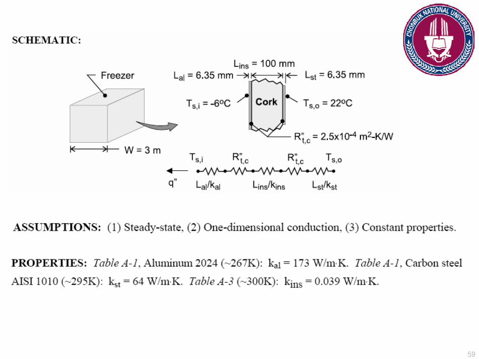
Problem 3.24Problem 3.24A commercial grade cubical freezer, 3 m on a side, has a composite wall consisting of an exterior sheet of 6.35-mm-thick plain carbon steel, an intermediate layer of 100-mm thick cork insulation, and an inner sheet of 6.35-mm thick aluminum alloy (2024). Adhesive interfaces between the insulation ans the metallic strips are each characterized by a thermal contact resistance of R”t,c= 2.5 x 10⁻⁴ m2K/W. What is the steady-state cooling load that must be maintained by the refrigerator under conditions for which the outer and inner surface temperatures are 22oC and -6oC respectively?
59
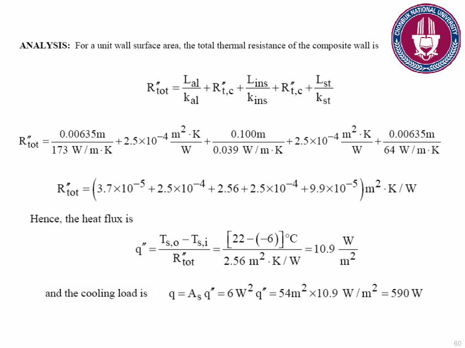
60
61
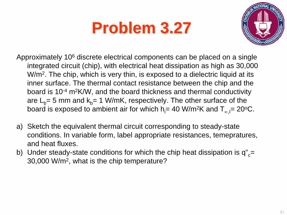
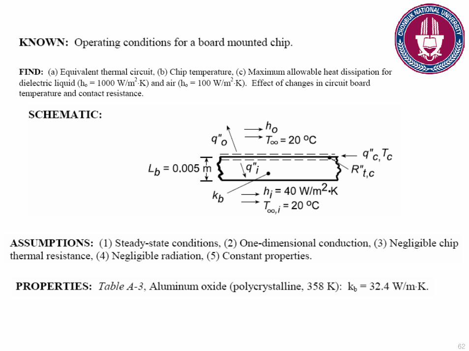
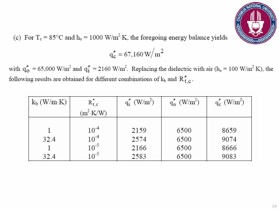
Problem 3.27Problem 3.27Approximately 106 discrete electrical components can be placed on a single
integrated circuit (chip), with electrical heat dissipation as high as 30,000 W/m2. The chip, which is very thin, is exposed to a dielectric liquid at its inner surface. The thermal contact resistance between the chip and the board is 10-4 m2K/W, and the board thickness and thermal conductivity are Lb= 5 mm and kb= 1 W/mK, respectively. The other surface of the board is exposed to ambient air for which hi= 40 W/m2K and T∞,I= 20oC.
a) Sketch the equivalent thermal circuit corresponding to steady-state conditions. In variable form, label appropriate resistances, temepratures, and heat fluxes.
b) Under steady-state conditions for which the chip heat dissipation is q”c= 30,000 W/m2, what is the chip temperature?
62

63
64
65
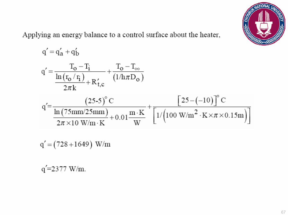
Problem 3.37Problem 3.37A thin electrical heater is wrapped around the outer surface of a long cylindrical tube whose inner surface is maintained at a temperature of 5oC. The tube wall has inner and outer radii of 25 and 75 mm, respectively, and a thermal conductivity of 10 W/mK. The thermal contact resistance between the heater and the outer surface of the tube (per unit length of the tube) is R’t,c= 0.01 mK/W. The outer surface of the heater is exposed to a fluid with T∞= -10oC and a convection coefficient of h = 100 W/m2K. Determine the heater power per unit length of tube required to maintain the heater at To= 25oC.

66
67
68
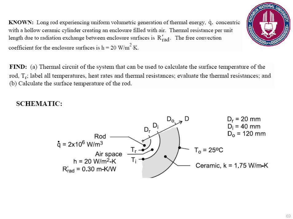
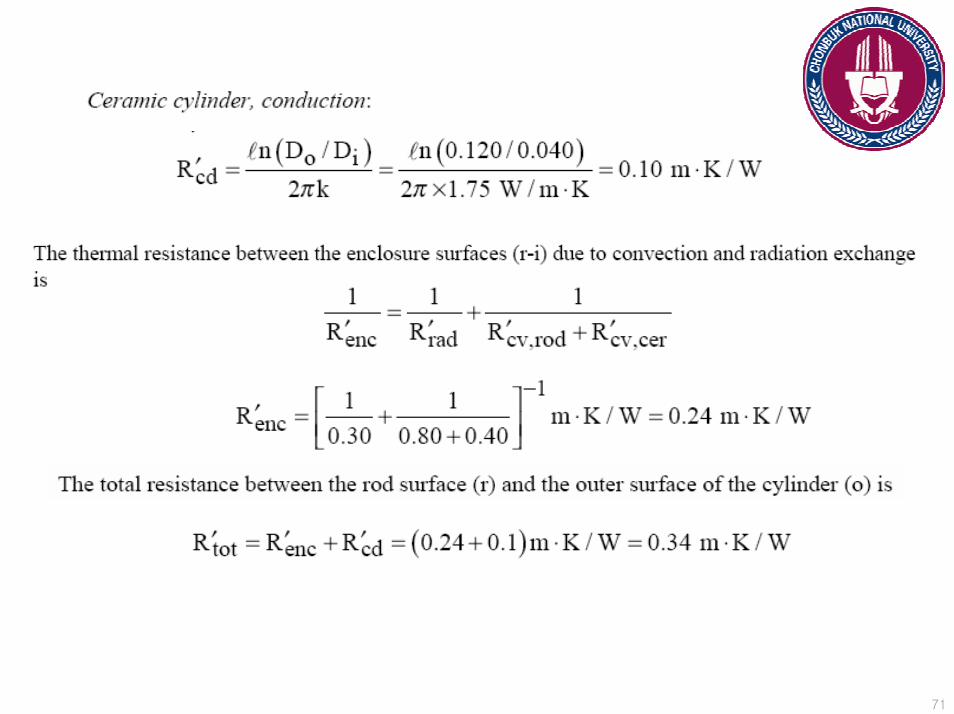
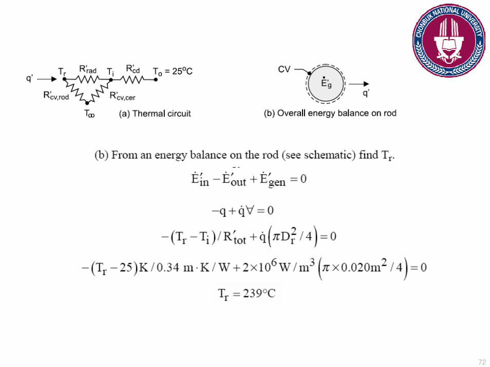
Problem 3.44Problem 3.44Electric current flows through a long rod generating thermal energy at a uniform
volumetric rate of q= 2 x 10⁶ W/m3. The rod is concentric with a hollow ceramic cylinder, creating an enclosure that is filled with air. The thermal resistance per unit length due to radiation between the enclosure surfaces is R”rad = 0.30 mK/W, and the coefficient associated with free convection in the enclosure is h = 20 W/m2K.
a) Construct a thermal circuit that can be used to calculate the surface temperature of the rd, Tr. Label all temperatures, heat rates, and thermal resistances, and evaluate each thermal resistance.
b) Calculate the surface temperature of the rod for the prescribed conditions.
69

70
71
72
73
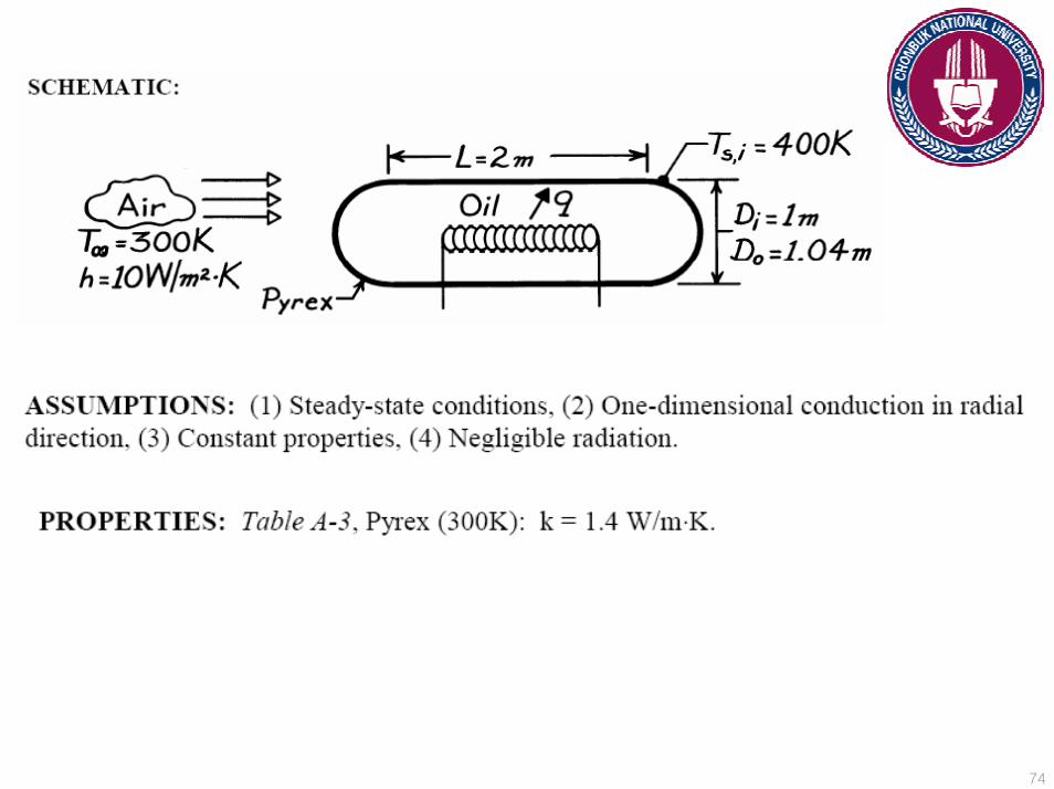
Problem 3.54Problem 3.54A storage tank consists of a cylindrical section that has a length and inner diameter of L= 2 m and Di = 1 m, respectively, and two hemispherical end sections. The tank is constructed from 20-mm-thick glass (Pyrex) and is exposed to ambient air for which the temperature is 300 K and the convection coefficient is 10 W/m2K. The tank is used to store heated oil, which maintains the inner surface at a temperature of 400 K. Determine the electrical power that must be supplied to a heater submerged in the oil if the prescribed conditions are to be maintained. Radiation effects may be neglected, and the Pyrex may be assumed to have a thermal conductivity of 1.4 W/mK.
74
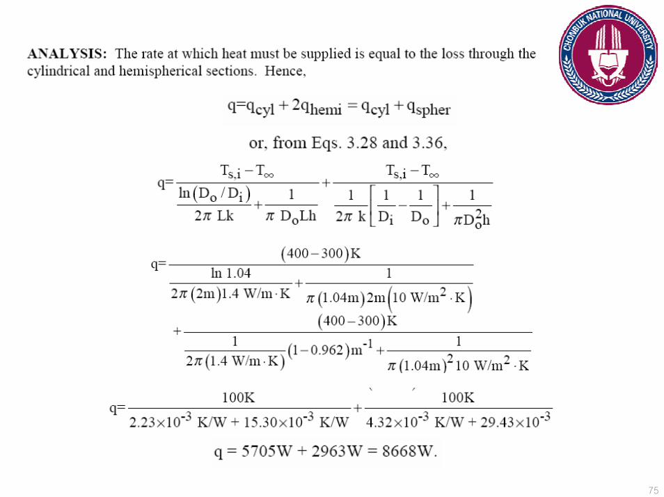
75
76
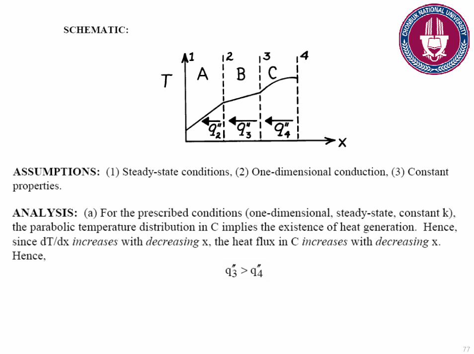
Problem 3.71Problem 3.71
The steady-state temperature distribution in a composite plane wall of three different materials, each of constant thermal conductivity, is shown in the figure.
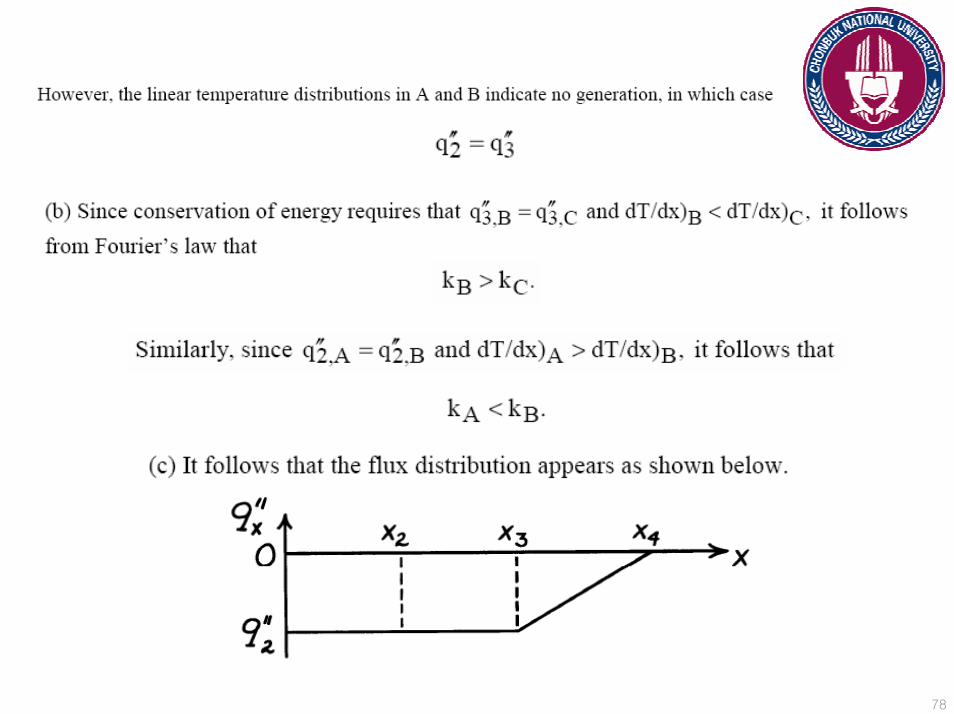
a) Comment on the relative magnitudes of q”2 and q”3 and q”3 and q”4.b) Comment on the relative magnitudes of kA and kB and kC.c) Sketch the heat flux as a function of x.
77
78

79
Problem 3.73Problem 3.73
Consider one-dimensional conduction in plane composite wall. The outer surfaces are exposed to a fluid at 25oC and a convection heat transfer coefficient of 1000 W/m2K. The middle wall B experiences uniform heat generation qB,, while there is no generation in the walls A and C. The temperatures at the interfaces are T1= 261oC and T2= 211oC.a) Assuming negligible contact resistance at the interfaces, determine the volumetric heat generation qB and the thermal conductivity kB.
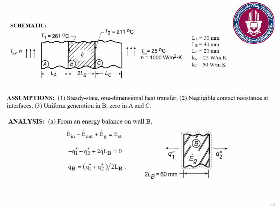
80

81
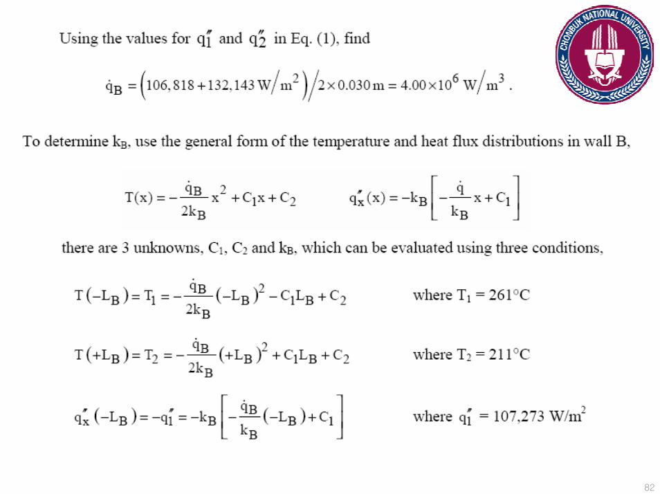
82
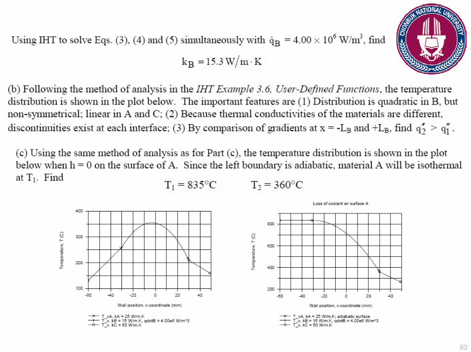
83
84
Problem 3.82Problem 3.82A quartz window of thickness L serves as a viewing port in a furnace used for annealing steel. The inner surface (x=0) of the window is irradiated with a uniform heat flux q”o due to emission from hot gases in the furnace. A fraction, β, of this radiation may be assumed to be absorbed at the inner surface while the remaining radiation is partially absorbed as it passes through the quartz. The volumetric heat generation due to this absorption may be described by an expression of the form
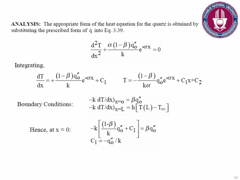
Where α is the absorption coefficient of the quartz. Convection heat transfer occurs from the outer surface (x=L) of the window to ambient air at T∞ and is characterized by the convection coefficient h. Convection and radiation emission from the inner surface may be neglected, along with radiation emission from the outer surface. Determine the temperature distribution in the quartz ezxpressingyour result in terms of the foregoing parameters.
"( ) (1 ) xoq x q e αβ α −= −
85
86

87
88
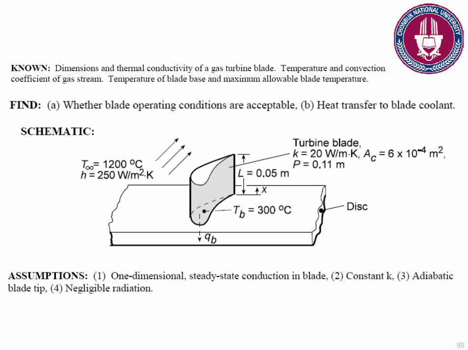
Problem 3.116Problem 3.116Turbine blades mounted to a rotating disc in a gas turbine engine are exposed to
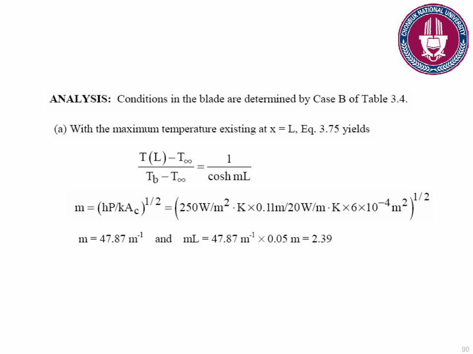
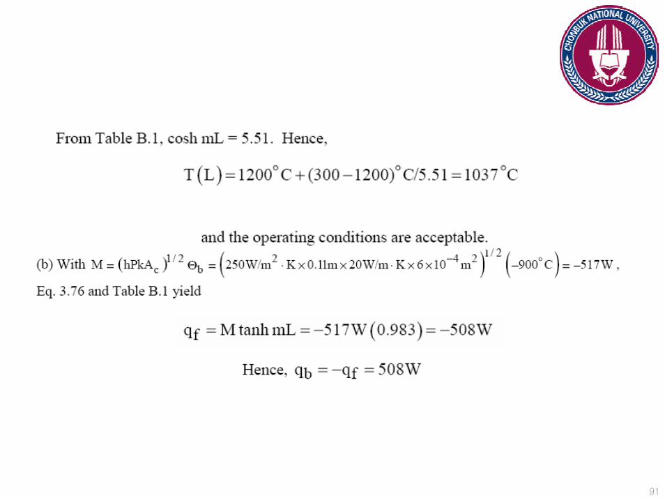
a gas stream that is at T∞ = 1200oC and maintains a convection coefficient of h = 250 W/m2K over the blade. The blades which are fabricated fro Inconel, k=20 W/mK, have a length of L= 50 mm. The blade profile has a uniform cross-sectional area of Ac= 6 x 10⁻⁴ m2 and a perimeter of P= 110 mm. A proposed blade-cooling scheme, which involves routing air through the supporting disc, is able to maintain the base of each blade at a temperature of Tb= 300oC.
a) If the maximum allowable blade temperature is 1050OC and the blade tip may be assumed to be adiabatic, is the proposed cooling scheme satisfactory?
b) For the proposed cooling scheme, what is the rate at which heat is transferred from each blade to the coolant?
89
90
91
Copyright © 2022 FDOKUMEN