Analysis of Metallic Ductile Fracture by extended Gurson ...
10
13th International Conference on Fracture June 16–21, 2013, Beijing, China -1- Analysis of Metallic Ductile Fracture by extended Gurson models Wei Jiang 1,* , Yazhi Li 1 , Yixiu Shu 1 , Zhenxing Fan 1 1 Department of Aeronautics, Northwestern Polythchnical University, 710000, China * Corresponding author: [email protected] Abstract Ductile fracture of metallic materials is usually the result of void nucleation, growth and coalescence. The original Gurson-Tvergaard (GT) model deals with the homogenous deformation related to void nucleation and growth. However, it takes no consideration on the localized deformation due to the void coalescence. In this paper extended GT damage models incorporating two different void coalescence criteria are developed, respectively. One of the void coalescence criteria is based on the plastic limit load model by Thomason; the other decides the onset of void coalescence by a critical equivalent plastic strain as a power law of stress triaxiality (defined by the ratio of the hydrostatic stress over the equivalent stress). Hence, void coalescence is controlled by physical mechanisms, rather than by a critical void volume fraction which cannot be taken as a constant. The extended constitutive models are implemented into an implicit finite element code via a user defined material subroutine (UMAT) in ABAQUS. Detail analyses are performed for a series of notched round tensile bars. The predictions of the fracture behavior based on the proposed approach, from void nucleation to final material failure, are compared with experiment data. Both results agree pretty well. In the end, the effects of stress triaxiality are discussed. Keywords ductile failure, mechanism-based approach, Gurson model, void coalescence 1. Introduction Mechanism-based fracture mechanics attempts to link micro-structural variables and continuum properties of material to macroscopic fracture behavior. The macroscopic ductile fracture process due to the presence of voids can be separated into two phases, the homogenous deformation with void nucleation and growth, and the localized deformation due to void coalescence (Zhang et al., 2000) [1].The famous porous material model for analyzing the ductile failure, in which the material yielding is coupled with damage (void volume fraction, f ) and hydrostatic stress, was proposed by Gurson (1977) [2]. Tvergaard (1981, 1982) [3], [4] modified Gurson model by introducing two adjustment factors to account for void interaction effects and material strain hardening. Needleman and Tvergaard (1984) [5] extended Gurson model to simulate the rapid loss of load carrying capacity during void coalescence. Chu and Needleman (1980) [6] supplemented it by various kinds of void nucleation criteria. In the early research, the criterion for the onset of void coalescence states that void coalescence starts at a critical void volume fraction c f which has tend to be regarded as a material constant. However, further studies show that c f depends strongly on parameters such as initial void volume fraction, void shape, void spacing, stress triaxiality, as well as strain hardening, etc.(Zhang et al., 2000; Pardoen and Hutchinson, 2000) [1], [7]. Thomason (1985, 1998) [8], [9] proposed a plastic limit load model for void coalescence. In this model, the start of void coalescence is controlled by the mechanism of the plastic localization in the void ligament, which is able to unify the material and stress states dependencies. Bao (2005) [10] conducted a series of experiments and finite element analyses on an aluminum alloy 2024-T351 and obtained a coalescence criterion in terms of the critical equivalent strain c E as a function of the stress triaxiality ratio T . When the macroscopic equivalent strain reaches the critical value c E , void coalescence occurs and the material quickly loses its load carrying capacity. However, Gao and Kim (2006) [11] argued that the extra parameter lode angle θ should be introduced and the critical equivalent strain should have the
-
Upload
khangminh22 -
Category
Documents
-
view
0 -
download
0
Transcript of Analysis of Metallic Ductile Fracture by extended Gurson ...

13th International Conference on Fracture June 16–21, 2013, Beijing, China
-1-
Analysis of Metallic Ductile Fracture by extended Gurson models
Wei Jiang1,*, Yazhi Li1, Yixiu Shu1, Zhenxing Fan1
1 Department of Aeronautics, Northwestern Polythchnical University, 710000, China
* Corresponding author: [email protected]
Abstract Ductile fracture of metallic materials is usually the result of void nucleation, growth and coalescence. The original Gurson-Tvergaard (GT) model deals with the homogenous deformation related to void nucleation and growth. However, it takes no consideration on the localized deformation due to the void coalescence. In this paper extended GT damage models incorporating two different void coalescence criteria are developed, respectively. One of the void coalescence criteria is based on the plastic limit load model by Thomason; the other decides the onset of void coalescence by a critical equivalent plastic strain as a power law of stress triaxiality (defined by the ratio of the hydrostatic stress over the equivalent stress). Hence, void coalescence is controlled by physical mechanisms, rather than by a critical void volume fraction which cannot be taken as a constant. The extended constitutive models are implemented into an implicit finite element code via a user defined material subroutine (UMAT) in ABAQUS. Detail analyses are performed for a series of notched round tensile bars. The predictions of the fracture behavior based on the proposed approach, from void nucleation to final material failure, are compared with experiment data. Both results agree pretty well. In the end, the effects of stress triaxiality are discussed. Keywords ductile failure, mechanism-based approach, Gurson model, void coalescence 1. Introduction Mechanism-based fracture mechanics attempts to link micro-structural variables and continuum properties of material to macroscopic fracture behavior. The macroscopic ductile fracture process due to the presence of voids can be separated into two phases, the homogenous deformation with void nucleation and growth, and the localized deformation due to void coalescence (Zhang et al., 2000) [1].The famous porous material model for analyzing the ductile failure, in which the material yielding is coupled with damage (void volume fraction, f ) and hydrostatic stress, was proposed by Gurson (1977) [2]. Tvergaard (1981, 1982) [3], [4] modified Gurson model by introducing two adjustment factors to account for void interaction effects and material strain hardening. Needleman and Tvergaard (1984) [5] extended Gurson model to simulate the rapid loss of load carrying capacity during void coalescence. Chu and Needleman (1980) [6] supplemented it by various kinds of void nucleation criteria. In the early research, the criterion for the onset of void coalescence states that void coalescence starts at a critical void volume fraction cf which has tend to be regarded as a material constant. However, further studies show that cf depends strongly on parameters such as initial void volume fraction, void shape, void spacing, stress triaxiality, as well as strain hardening, etc.(Zhang et al., 2000; Pardoen and Hutchinson, 2000) [1], [7]. Thomason (1985, 1998) [8], [9] proposed a plastic limit load model for void coalescence. In this model, the start of void coalescence is controlled by the mechanism of the plastic localization in the void ligament, which is able to unify the material and stress states dependencies. Bao (2005) [10] conducted a series of experiments and finite element analyses on an aluminum alloy 2024-T351 and obtained a coalescence criterion in terms of the critical equivalent strain cE as a function of the stress triaxiality ratio T . When the macroscopic equivalent strain reaches the critical value cE , void coalescence occurs and the material quickly loses its load carrying capacity. However, Gao and Kim (2006) [11] argued that the extra parameter lode angleθ should be introduced and the critical equivalent strain should have the

13th International Conference on Fracture June 16–21, 2013, Beijing, China
-2-
form ( ),cE T θ . In this paper, two different void coalescence criteria are combined with the original GT model to simulate the whole process of voids nucleation, growth and coalescence. Axisymmetric round tensile bars with different notch root radii are simulated using the extended damage models to investigate the variation of critical damage at coalescence as a function of stress triaxiality. 2. Extended Damage Models 2.1. Modeling the void growth process The growth of a void and the associated macroscopic softening is adequately captured by GT constitutive relationship. The most widely used form, which applies to strain hardening materials under the assumption of isotropic hardening, has the shape
222
1 332 cosh 1 02qq pq f q f
σ σ⎛ ⎞⎛ ⎞Φ = + − − − =⎜ ⎟ ⎜ ⎟
⎝ ⎠ ⎝ ⎠, (1)
where p represents the macroscopic hydrostatic pressure 1 :3
p Iσ= − , (2)
q denotes the macroscopic Mises equivalent stress 3 :2
q s s= , (3)
σ is stress tensor; s is stress deviator; I is the second order identity tensor; ( )pmσ ε is the current
flow stress of the fully dense matrix material as a function of pmε , the equivalent plastic strain in the
matrix; and f is the current void volume fraction in the material. Tvergaard (1980, 1981) [3] introduced the constants 1q , 2q and 2
3 1q q= to account for void interaction effects due to multiple-void arrays and to give a better agreement with experimental data. The hardening of the matrix material is described through ( )p
mσ σ ε= . The evolution of pmε is
assumed to be governed by the equivalent plastic work expression: ( )1 :p p
mf d dσ ε σ ε− = , (4)
where pdε is the macroscopic plastic strain rate tensor; pmdε is equivalent plastic strain rate of the
matrix material. The change in volume fraction of the voids is due partly to the growth of existing voids and partly to the nucleation of voids. It can be expressed as [12]:
growth nucleationdf df df= + , (5)
with ( )1 :p
growthdf f d Iε= − , (6) Nucleation of voids can occur as a result of micro-cracking and/or decohesion of the particle-matrix interface. It can be assumed to be strain controlled, so that the rate of increase of void volume fraction due to nucleation of new voids is given by
pnucleation mdf Adε= , (7)

13th International Conference on Fracture June 16–21, 2013, Beijing, China
-3-
The void nucleation intensity, A is a function of pmε the equivalent plastic strain in the matrix
material, and is assumed to follow a normal distribution as suggested by Chu and Needleman (1980) [6]:
21exp22
pN m N
NN
fAss
ε επ
⎡ ⎤⎛ ⎞−⎢ ⎥= − ⎜ ⎟⎢ ⎥⎝ ⎠⎣ ⎦
, (8)
where Nf is determined so that the total void volume nucleated is consistent with the volume fraction of particles; Nε is the mean equivalent plastic strain for void nucleation; and Ns is the standard deviation of the distribution. 2.2. Void coalescence criterion 2.2.1 Plastic limit load criterion Thomason (1985, 1998) [8] found that the localized deformation mode by intervoid matrix necking can be characterized by a plastic limit load which is not fixed but is strongly dependent on the void geometry and stress states. The condition for void coalescence can be written as:
1 1Lσ σ= , (9)
where 1Lσ represents the capacity of the material to resist void coalescence; and 1σ is the maximum
principal stress at current yield surface of a material point. Using a 3D unit cell containing an axisymmetric ellipsoidal void, Thomason acquired the plastic limit load to void coalescence with the following form
2 1/2 21
21L
x xz
x
R RRX R X X
πσ α βσ
− −⎛ ⎞⎛ ⎞ ⎛ ⎞⎛ ⎞⎜ ⎟= + −⎜ ⎟ ⎜ ⎟⎜ ⎟⎜ ⎟− ⎝ ⎠ ⎝ ⎠⎝ ⎠⎝ ⎠, (10)
where xR , zR and X are the current radii of the ellipsoidal void in the x- and z- axes and the current length of the cell in the x-axis, respectively; the local coordinates system is constructed so that x-, y- and z- axes represent the minor, medium and maximum principal stress directions. α and β are constants which are suggested as 0.1 and 1.2 by Thomason. Pardeon and Hutchinson (2000) [7] conducted a large number of cells calculations and found the dependence of α andβ on hardening exponent n . Their simulation results showed thatβ is almost a constant and can be taken as 1.24 while
( ) 20.1 0.217 4.83 (0 0.3)n n n nα = + + ≤ ≤ , (11) If the void is assumed to be always spherical, the void/matrix geometry in Eq. 10 can be directly determined from the current void volume fraction f and current principal strain 1ε , 2ε , 3ε by following equations (Zhang, 2001)[13]:
1 2 3334x y z
fR R R eε ε ε
π+ += = = , (12)
1 2 / 2X Y eε ε+= = , (13) 2.2.2 Equivalent plastic strain criterion By assuming the existence of a periodic distribution of voids, the material can be considered as an array of cubic blocks with each block being a unit cell having a void at its center. Failure of the unit cell occurs when localization of plastic flow takes place in the ligament (Koplik and Needleman,

13th International Conference on Fracture June 16–21, 2013, Beijing, China
-4-
1988) [14]. In macroscopic, a critical value of equivalent plastic strain is always used as a measurement of material ductility. Therefore, critical equivalent plastic strain can be used to denote material failure by void coalescence. To implement this concept, a possible approach is to establish a failure criterion based on equivalent plastic strain at the location where failure is most likely to initiate. In practical, for axisymmetric round tensile bars, failure always initiates in the center of the minimum section in specimens, where corresponds to the site with the highest stress triaxiality. In addition, stress triaxiality is often used as the sole parameter to characterize the effect of the triaxial stress states on ductile fracture. So the critical equivalent plastic strain can be established as a function of the stress trixiality ratioT . The power law form of the equivalent plastic strain criterion for API X65 steel proposed by Oh et al. (2007) [15] can be written as:
10.029.3 54.1 += − Tef eE , (14)
with
qpT −= , (15)
where efE represents the critical equivalent plastic strain. This criterion is also used to develop extended damage model in this paper. 2.3. Post coalescence response The *f function, introduced by Tvergaard and Needleman (1984) [5], is adopted, to account for the effects of rapid void coalescence at failure. After void volume fraction reaches critical value determined by voids coalescence criteria, f is replaced by *f in the extended damage models.
( )* *
c
u cc c c
F c
f for f ff f ff f f for f f
f f
<⎧⎪= −⎨ + − ≥⎪ −⎩
, (16)
where cf is the critical void volume fraction at which voids begin coalesce; *11/uf q= is the *f value
at zero stress; and Ff denotes the void volume fraction at final complete failure. 3. Finite element applications API X65 steel which is main pipe material largely utilized in gas transportation networks is discussed in this paper. To investigate the effect of triaxial stress states on tensile ductility of the material, three tensile round bar specimens with different notch root radii are analyzed, see Fig. 1. These specimens are also analyzed by Oh et al. (2007) [15] and the present simulation results are compared to their experimental data. The extended damage models described in the previous section are implemented in ABAQUS via a user defined material subroutine (UMAT). Two critical numerical procedures are involved in the finite element implementations. The integration of the rate form constitutive equations is following the backward Euler method by Aravas (1987) [16]. In an implicit code, the linearization modulus is needed to construct the stiffness matrix (Jacobin) for Newton scheme which is used to solve the global equilibrium equations. The explicit consistent tangent modulus based on a return mapping
13th International Conference on Fracture June 16–21, 2013, Beijing, China
-5-
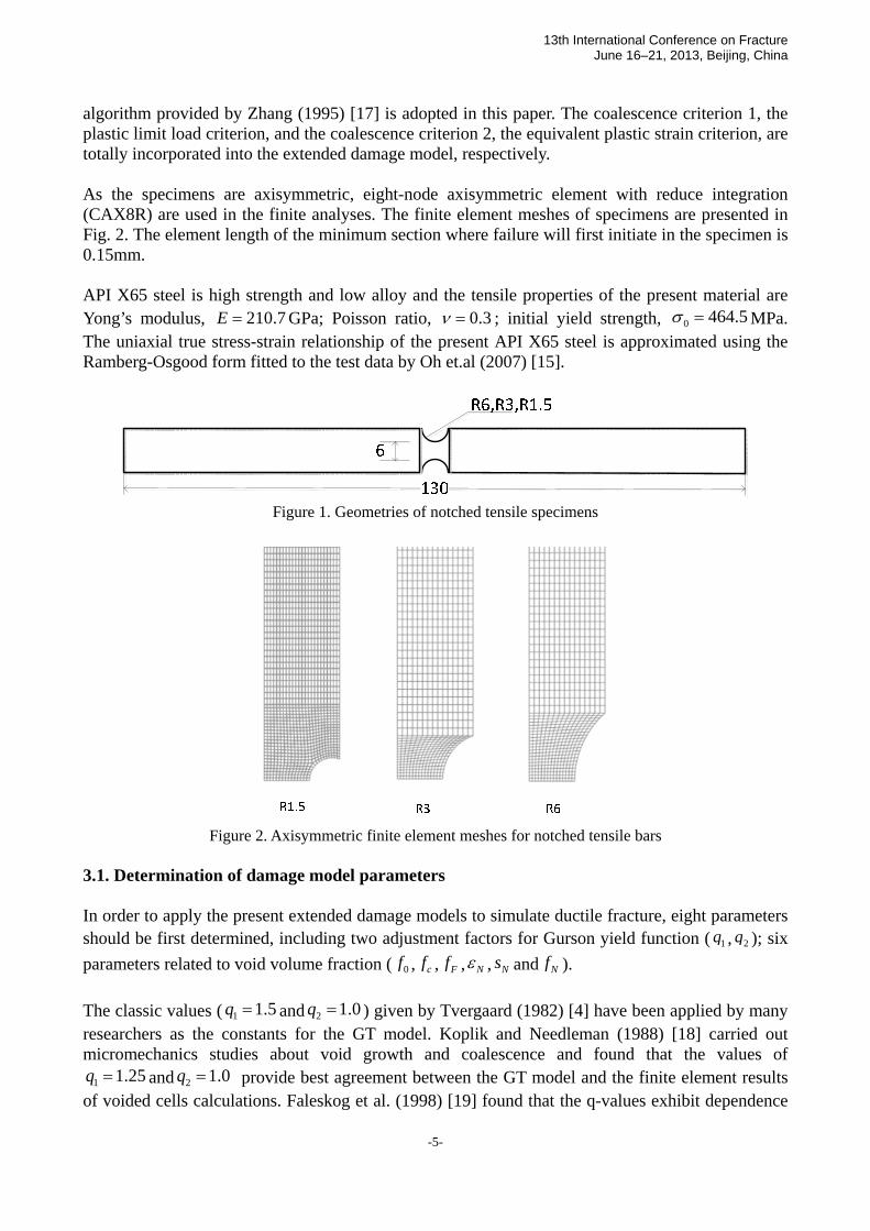
algorithm provided by Zhang (1995) [17] is adopted in this paper. The coalescence criterion 1, the plastic limit load criterion, and the coalescence criterion 2, the equivalent plastic strain criterion, are totally incorporated into the extended damage model, respectively. As the specimens are axisymmetric, eight-node axisymmetric element with reduce integration (CAX8R) are used in the finite analyses. The finite element meshes of specimens are presented in Fig. 2. The element length of the minimum section where failure will first initiate in the specimen is 0.15mm. API X65 steel is high strength and low alloy and the tensile properties of the present material are Yong’s modulus, 210.7E = GPa; Poisson ratio, 0.3ν = ; initial yield strength, 0 464.5σ = MPa. The uniaxial true stress-strain relationship of the present API X65 steel is approximated using the Ramberg-Osgood form fitted to the test data by Oh et.al (2007) [15].
Figure 1. Geometries of notched tensile specimens
Figure 2. Axisymmetric finite element meshes for notched tensile bars 3.1. Determination of damage model parameters In order to apply the present extended damage models to simulate ductile fracture, eight parameters should be first determined, including two adjustment factors for Gurson yield function ( 1q , 2q ); six parameters related to void volume fraction ( 0f , cf , Ff , Nε , Ns and Nf ). The classic values ( 1 1.5q = and 2 1.0q = ) given by Tvergaard (1982) [4] have been applied by many researchers as the constants for the GT model. Koplik and Needleman (1988) [18] carried out micromechanics studies about void growth and coalescence and found that the values of
1 1.25q = and 2 1.0q = provide best agreement between the GT model and the finite element results of voided cells calculations. Faleskog et al. (1998) [19] found that the q-values exhibit dependence

13th International Conference on Fracture June 16–21, 2013, Beijing, China
-6-
on both the hardening exponent ( n ) and the ratio of initial yield strength over Young’s modulus ( 0 / Eσ ). The studies of Kim et al. (2004) [20] have shown that, for a given material, the q-parameters should vary with stress triaxialities. The nucleation parameters, Nε and 0.1Ns = , determined by Chu and Needleman (1980) [6], are considered reasonable values for the current application. 0.04Nf = is also suggested and is widely used by many researchers. However, the API x65 steel is a high-grade pipeline steel which is very clean steel and thus void nucleation is not significant and also delayed until very late in the deformation process. For this reason a much smaller value of Nf , 0.0008 is adopted in this study. Some authors suggests that, as a first approximation, initial void volume fraction 0f could be taken as the volume fraction of MnS inclusions, which is estimated from Franklin’s formula [21]
0.0010.054 %%vf S
Mn⎛ ⎞= −⎜ ⎟⎝ ⎠
, (18)
where, %S and %Mn are the weight-% of sulfur and manganese, respectively. While voids coalescence is automatically determined by two type’s criteria in the extended damage models, 0f is the only unknown parameter and is to be fitted. The void volume fraction at final fracture Ff is strongly dependent on 0f . Since Ff has been considered as an unimportant parameter, it can be extrapolated from the empirical equation by Zhang (2001) [13]:
00.15 2Ff f= + , (19) In the present study, two sets of damage model parameters are involved. For these two groups,
Nε , Ns and Nf are to be take the same values as discussed previously; 0f is determined by fitting to the experiment results for one notched tensile bar and then with this 0f , the void volume fraction at final fracture, Ff is obtained by Eq. 19. The critical coalescence porosity cf is decided by the two coalescence criteria: plastic limit load criterion and equivalent plastic strain criterion. The q-values are also disparate for the two groups. The classic values ( 1 1.5q = and 2 1.0q = ) are adopted in the first group. For the second, 1 1.704q = and 2 0.846q = are interpolated from the Faleskog’s tabulated results based on the measured values of hardening exponent ( n ) and the ratio of initial yield strength over Young’s modulus ( 0 / Eσ ). Both sets of damage model parameters are illustrated in Table 1.
Table 1. Damage models parameters Nε Ns Nf 0f cf Ff 1q 2q
Set1 0.3 0.1 0.0008 0.000125 Criteria1 0.15025 1.5 1.0 Set2 0.3 0.1 0.0008 0.0005 Criteria2 0.151 1.704 0.846
3.2. Comparison with experimental results The finite element analyses are applied to predict mechanical behavior for the notched tensile bars that had notch root radii of 6mm, 3mm and 1.5 mm. These specimens have different levels of stress triaxiality. Porous metal material based on Gurson plasticity theory is also provided by ABAQUS in both implicit and explicit code; however, the failure definition is only available in
13th International Conference on Fracture June 16–21, 2013, Beijing, China
-7-
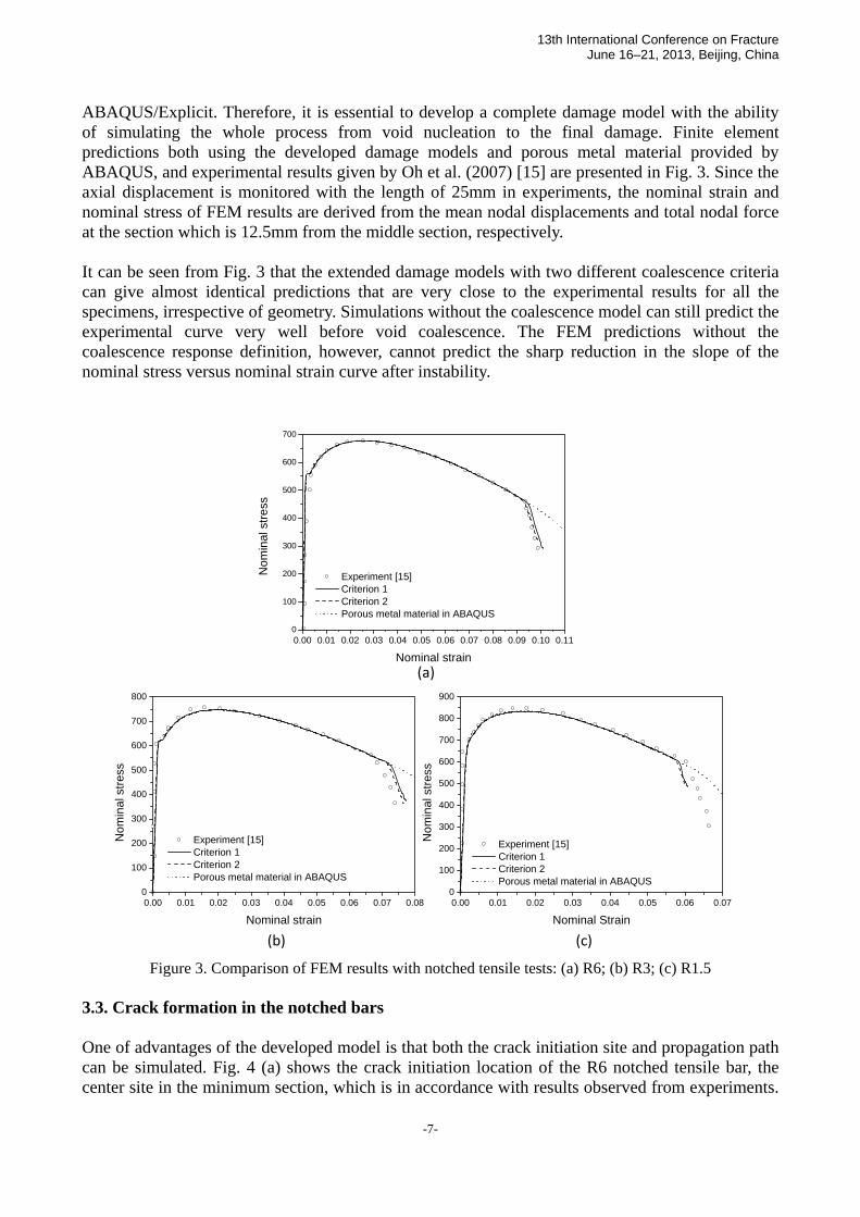
ABAQUS/Explicit. Therefore, it is essential to develop a complete damage model with the ability of simulating the whole process from void nucleation to the final damage. Finite element predictions both using the developed damage models and porous metal material provided by ABAQUS, and experimental results given by Oh et al. (2007) [15] are presented in Fig. 3. Since the axial displacement is monitored with the length of 25mm in experiments, the nominal strain and nominal stress of FEM results are derived from the mean nodal displacements and total nodal force at the section which is 12.5mm from the middle section, respectively. It can be seen from Fig. 3 that the extended damage models with two different coalescence criteria can give almost identical predictions that are very close to the experimental results for all the specimens, irrespective of geometry. Simulations without the coalescence model can still predict the experimental curve very well before void coalescence. The FEM predictions without the coalescence response definition, however, cannot predict the sharp reduction in the slope of the nominal stress versus nominal strain curve after instability.
0.00 0.01 0.02 0.03 0.04 0.05 0.06 0.07 0.08 0.09 0.10 0.110
100
200
300
400
500
600
700
Nom
inal
stre
ss
Nominal strain
Experiment [15] Criterion 1 Criterion 2 Porous metal material in ABAQUS
0.00 0.01 0.02 0.03 0.04 0.05 0.06 0.07 0.080
100
200
300
400
500
600
700
800
Nom
inal
stre
ss
Nominal strain
Experiment [15] Criterion 1 Criterion 2 Porous metal material in ABAQUS
0.00 0.01 0.02 0.03 0.04 0.05 0.06 0.070
100
200
300
400
500
600
700
800
900
Nom
inal
stre
ss
Nominal Strain
Experiment [15] Criterion 1 Criterion 2 Porous metal material in ABAQUS
(a)
(b) (c)
Figure 3. Comparison of FEM results with notched tensile tests: (a) R6; (b) R3; (c) R1.5 3.3. Crack formation in the notched bars One of advantages of the developed model is that both the crack initiation site and propagation path can be simulated. Fig. 4 (a) shows the crack initiation location of the R6 notched tensile bar, the center site in the minimum section, which is in accordance with results observed from experiments.

13th International Conference on Fracture June 16–21, 2013, Beijing, China
-8-
Fig. 4 (b) illustrates the crack growth path, from the center to the free surface through the minimum section of the specimen. The void volume fraction at crack initiation is presented in Fig. 4 (c) and the highest void volume fraction site appears in the center of notched bars with no surprise.
Damage element
Figure 4. The FEM results of R6 notched tensile bar: (a) (b) Damage elements at and after crack initiation; (c) The void volume fraction at crack initiation
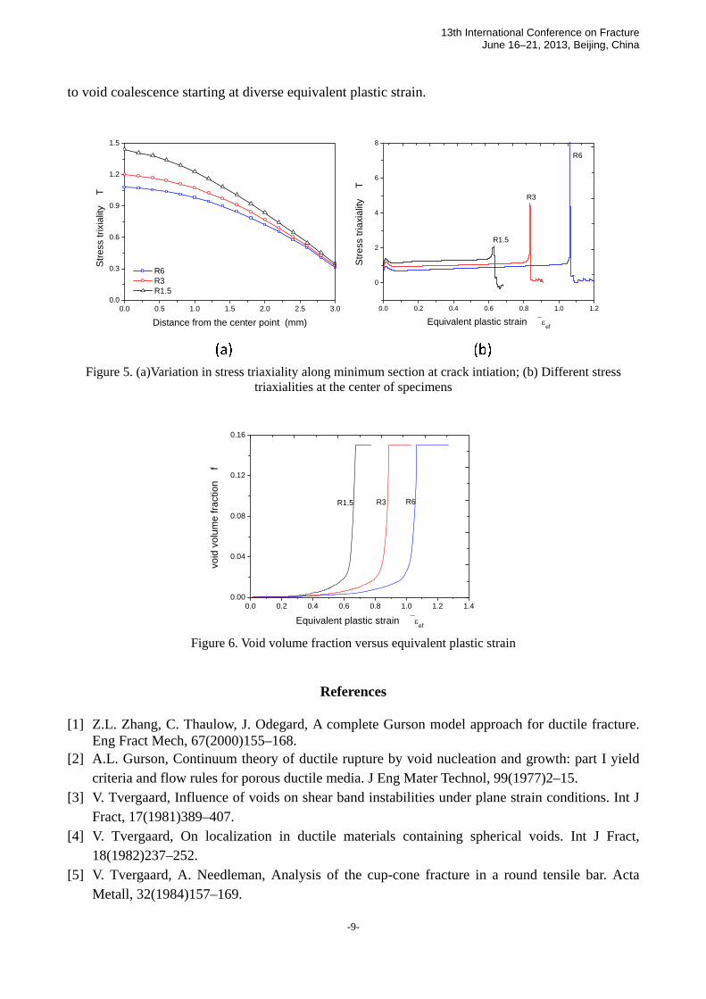
3.4. The effect of stress triaxiality For each specimen, stress triaxiality is highest at the center and lowest at the free edge. Fig. 5(a) demonstrates the stress triaxiality value along the minimum section at the loading level corresponding to the onset of crack. Higher values of stress triaxiality together with increased plastic deformation in the center region of notched specimens accelerate crack initiation and growth according to the GT constitutive relationship. Thus, it is not surprising to find that crack initiates at the center of specimens. For specimens with different notch root radii, various stress triaxialities are determined by geometry. Larger notch root radii results in smaller stress trixiality ratio. The curve of stress triaxiality ratio T versus equivalent plastic strain efε at the center of specimen with load proceeding is presented in Fig. 5(b). Various stress triaxialities lead to void coalescence at different plastic deformation measured by equivalent plastic strain, illustrated in Fig. 6. 4. Concluding remarks By incorporating two coalescence criteria, the extended damage models succeed in simulating the ductile failure in round tensile bars and also provide a practical approach to simulate the crack formation and propagation in small-scale tensile specimens. The present predictions show that: (1) The extended damage models with two different coalescence criteria can give almost identical predictions that are very close to the experimental results for all the specimens. (2) For each round tensile bar, crack initiates in the center of specimen where the highest stress triaxiatity and largest void volume fraction appear. In addition, crack propagation along the minimum section in specimens. (3) Distinct geometries represent different stress triaxiatities and different stress triaxiatities lead
13th International Conference on Fracture June 16–21, 2013, Beijing, China
-9-
to void coalescence starting at diverse equivalent plastic strain.
0.0 0.5 1.0 1.5 2.0 2.5 3.00.0
0.3
0.6
0.9
1.2
1.5
Stre
ss tr
ixia
lity
T
Distance from the center point (mm)
R6 R3 R1.5
0.0 0.2 0.4 0.6 0.8 1.0 1.2
0
2
4
6
8
R6
R3
Stre
ss tr
iaxi
ality
T
Equivalent plastic strain ⎯εef
R1.5
Figure 5. (a)Variation in stress triaxiality along minimum section at crack intiation; (b) Different stress triaxialities at the center of specimens
0.0 0.2 0.4 0.6 0.8 1.0 1.2 1.40.00
0.04
0.08
0.12
0.16
R6R3
void
vol
ume
fract
ion
f
Equivalent plastic strain ⎯εef
R1.5
Figure 6. Void volume fraction versus equivalent plastic strain
References
[1] Z.L. Zhang, C. Thaulow, J. Odegard, A complete Gurson model approach for ductile fracture.
Eng Fract Mech, 67(2000)155–168. [2] A.L. Gurson, Continuum theory of ductile rupture by void nucleation and growth: part I yield
criteria and flow rules for porous ductile media. J Eng Mater Technol, 99(1977)2–15. [3] V. Tvergaard, Influence of voids on shear band instabilities under plane strain conditions. Int J
Fract, 17(1981)389–407. [4] V. Tvergaard, On localization in ductile materials containing spherical voids. Int J Fract,
18(1982)237–252. [5] V. Tvergaard, A. Needleman, Analysis of the cup-cone fracture in a round tensile bar. Acta
Metall, 32(1984)157–169.

13th International Conference on Fracture June 16–21, 2013, Beijing, China
-10-
[6] C.C. Chu, A. Needleman, Void nucleation effects in biaxial stretched sheets. J Eng Mater Technol, 102(1980) 249–256.
[7] T. Pardoen, J.W. Hutchinson, An extended model for void growth and coalescence. J Mech Phys Solid, 48(2000)2467–2512.
[8] P.F. Thomason, A three-dimensional model for ductile fracture by the growth and coalescence of micro-voids. Acta Metall, 33(1985)1087–1095.
[9] P.F. Thomason, A view on ductile-fracture modelling. Fatigue Fract Eng M, 21(1998)1105–1022.
[10] Y. Bao, Dependence of ductile crack formation in tensile tests on stress trixiality, stress and strain ratios. Eng Frcat Mech, 72(2005)505–522.
[11] X.S. Gao, J. Kim, Modeling of ductile fracture: Significance of void coalescence. Int J Solids Struct, 43(2006) 6277–6293.
[12] ABAQUS, Standard User’s Manual, Version 6.11, 2012. [13] Z.L. Zhang, A complete Gurson model, in: M.H. Alibadi, Nonlinear Fracture and Damage
Mechanics, WIT Press, Southampton, UK, 2001, pp. 223–248. [14] J. Koplik, A. Needleman, Void growth and coalescence in porous plastic solids. Int J Solids
Struct, 24(1988)835–853. [15] C.K. Oh, Y.J. Kim, J.H. Baek, W.S Kim, Development of stress-modified fracture strain for
ductile failure of API X65 steel. Int J Fract, 143(2007)119–133. [16] N. Aravas, On the numerical integration of a class of pressure-dependent plasticity models. Int
J Numer Meth Eng, 24(1987)1395–1416. [17] Z.L. Zhang, Explicit consistent tangent moduli with a return mapping algorithm for
pressure-dependent elastoplasticity models. Comput Method Appl M, 121(1995)29–44. [18] J. Koplik, A. Needleman, Void growth and coalescence in porous plastic solids. Int J Solids
Struct, 24(1988)835–853. [19] J. Faleskog, C.F. Shih, Micromechanics of coalescence I: Synergistic effects of elasticity,
plastic yielding and multi-size-scale voids. J Mech Phys Solids, 45(1997)21–45. [20] J. Kim, X.S. Gao, T.S. Srivatsan, Modeling of void growth in ductile solids: effects of stress
triaxiality and initial porosity. Eng Fract Mech, 71(2004) 379–400. [21] B.A. Bilby, I.C. Howard, Z.H. Li, Prediction of the first spinning cylinder test using ductile
damage theory. Fatigue Fract Eng M, 16(1992) 1–20.