The Effect of Steel Beam Elastic Restraint on the Critical ...
Upload
khangminh22Category
view
4download
0
Strength and Durability for Life®
DESIGN
Thrust Restraint Design for Ductile Iron PipeSeventh Edition
Last Revised: May 2016
1
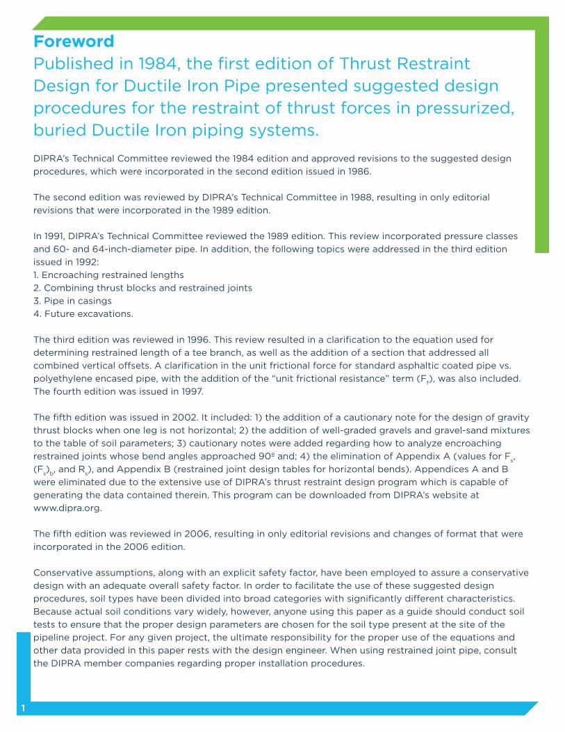
ForewordPublished in 1984, the first edition of Thrust Restraint Design for Ductile Iron Pipe presented suggested design procedures for the restraint of thrust forces in pressurized, buried Ductile Iron piping systems.
DIPRA’s Technical Committee reviewed the 1984 edition and approved revisions to the suggested design
procedures, which were incorporated in the second edition issued in 1986.
The second edition was reviewed by DIPRA’s Technical Committee in 1988, resulting in only editorial
revisions that were incorporated in the 1989 edition.
In 1991, DIPRA’s Technical Committee reviewed the 1989 edition. This review incorporated pressure classes
and 60- and 64-inch-diameter pipe. In addition, the following topics were addressed in the third edition
issued in 1992:
1. Encroaching restrained lengths
2. Combining thrust blocks and restrained joints
3. Pipe in casings
4. Future excavations.
The third edition was reviewed in 1996. This review resulted in a clarification to the equation used for
determining restrained length of a tee branch, as well as the addition of a section that addressed all
combined vertical offsets. A clarification in the unit frictional force for standard asphaltic coated pipe vs.
polyethylene encased pipe, with the addition of the “unit frictional resistance” term (Ff), was also included.
The fourth edition was issued in 1997.
The fifth edition was issued in 2002. It included: 1) the addition of a cautionary note for the design of gravity
thrust blocks when one leg is not horizontal; 2) the addition of well-graded gravels and gravel-sand mixtures
to the table of soil parameters; 3) cautionary notes were added regarding how to analyze encroaching
restrained joints whose bend angles approached 90º and; 4) the elimination of Appendix A (values for Fs,
(Fs)
b, and R
s), and Appendix B (restrained joint design tables for horizontal bends). Appendices A and B
were eliminated due to the extensive use of DIPRA’s thrust restraint design program which is capable of
generating the data contained therein. This program can be downloaded from DIPRA’s website at
www.dipra.org.
The fifth edition was reviewed in 2006, resulting in only editorial revisions and changes of format that were
incorporated in the 2006 edition.
Conservative assumptions, along with an explicit safety factor, have been employed to assure a conservative
design with an adequate overall safety factor. In order to facilitate the use of these suggested design
procedures, soil types have been divided into broad categories with significantly different characteristics.
Because actual soil conditions vary widely, however, anyone using this paper as a guide should conduct soil
tests to ensure that the proper design parameters are chosen for the soil type present at the site of the
pipeline project. For any given project, the ultimate responsibility for the proper use of the equations and
other data provided in this paper rests with the design engineer. When using restrained joint pipe, consult
the DIPRA member companies regarding proper installation procedures.
2
Table of Contents
Thrust Restraint
Thrust Force
Design Pressure
Pipe-soil Structure
Thrust Blocks
Restrained Joints
Horizontal Bends
Unit Frictional Force, Fs
Polyethylene Encasement
Unit Bearing Resistance, Rs
Vertical Down Bends
Vertical Up Bends
Tees
Reducers
Dead Ends
Encroaching Restrained Lengths
Equal Angle Vertical Offset
Combined Horizontal Equal Angle Bends
Combined Vertical Equal Angle Offsets
Restrained Length
Select Backfill Considerations
Combining Thrust Blocks and Restrained Joints
Pipe in a Casing
Future Excavations
Deflected Unrestrained Ductile Iron Pipe Joints
Computer Program
Restrained Length Calculation Procedure
Nomenclature
References
Tables
1. Horizontal Bearing Strengths
2. Dimensions and Unit Weights of Pipe
and Water
3. Suggested Values for Soil Parameters and
Reduction Constant, Kn
4. Soil Classification Chart
Figures
1. Push-on Joint
2. Internally Balanced Force
3. Thrust Force
4. Thrust Force for Various Configurations
5. Bearing Block
6. Gravity Thrust Block
7. Horizontal Bend /Vertical Up Bend
8. Unit Normal Forces on Pipe
9. Standard ANSI /AWWA C150/A21.50
Laying Conditions
10. Vertical Down Bends
11. Tees
12. Reducers
13. Dead Ends
14. Equal Angle Vertical Offset
15. Combined Horizontal Equal Angle Bends
16. Combined Vertical Equal Angle Offsets
3
4
6
6
6
8
9
10
10
11
14
14
15
16
16
17
17
18
19
20
20
20
20
20
20
21
21
22
22
7
12
13
13
3
4
4
5
6
8
9
10
12
14
15
16
16
17
18
19

Thrust Restraint
Ductile Iron Pipe and fittings are most often joined
with push-on (Figure 1) or mechanical joints. Neither
of these joints provides significant restraint against
longitudinal separation other than the friction
between the gasket and the plain end of the pipe
or fitting. Tests have shown that this frictional
resistance in the joint is unpredictable, varying
widely with installation conditions and other
factors that are insignificant in other respects. Thus,
these joints should be considered as offering no
longitudinal restraint for design purposes.
At many locations in an underground or
aboveground pipeline, the configuration of the
pipeline results in unbalanced forces of hydrostatic
or hydrodynamic origin that, unless restrained, can
result in joint separation.
Generically, these unbalanced hydrostatic and
hydrodynamic forces are called Thrust Forces. In
the range of pressures and fluid velocities found in
waterworks or wastewater piping, the hydrodynamic
thrust forces are generally insignificant in relation
to the hydrostatic thrust forces and are usually
ignored. Simply stated, thrust forces occur at any
point in the piping system where the direction or
cross-sectional area of the waterway changes.
Thus, there will be thrust forces at bends, reducers,
offsets, tees, wyes, dead ends, and valves.
Balancing thrust forces in underground pipelines is
usually accomplished with bearing or gravity thrust
blocks, restrained joint systems, or combinations
of these methods. Presented herein is a general
discussion of the nature of thrust forces as well as
suggested approaches to the design of both thrust
block and restrained joint systems for balancing
these forces. The suggested design approaches are
conservatively based on accepted principles of soil
mechanics.
3
FIGURE 1
Push-on Joint

Thrust Force
The internal hydrostatic pressure acts perpendicularly
on any plane with a force equal to the pressure (P)
times the area (A) of the plane. All components
of these forces acting radially within a pipe are
balanced by circumferential tension in the wall
of the pipe. Axial components acting on a plane
perpendicular to the pipe through a straight section
of the pipe are balanced internally by the force
acting on each side of the plane (Figure 2).
Consider, however, the case of a bend as shown in
Figure 3. The forces PA acting axially along each
leg of the bend are not balanced. The vector sum of
these forces is shown as T. This is the thrust force. In
order to prevent separation of the joints, a reaction
equal to and in the opposite direction of T must be
established.
4
FIGURE 2
Internally Balanced Force
FIGURE 3
Thrust Force
T = 2 PA sin (Ø/2)

Figure 4 depicts the net thrust force at various other
configurations. In each case the expression for T can
be derived by the vector addition of the axial forces.
5
FIGURE 4
Thrust Force for Various Configurations
ReducerTee
Dead End
Closed Valve
Wye

Design Pressure
The design pressure, P, is the maximum pressure
to which the pipeline will be subjected, with
consideration given to the vulnerability of the pipe-
soil system when the pressure is expected to be
applied. In most cases this will be the test pressure
of the pipe, applied shortly after installation when
the pipe-soil system is normally most vulnerable.
Pipe-soil Structure
For buried pipelines, thrust restraint is achieved by
transferring the thrust force to the soil structure
outside the pipe. The objective of the design is to
distribute the thrust forces to the soil structure in
such a manner that damage does not occur to the
restrained pipe system and joint separation does not
occur in unrestrained joints.
Thrust Blocks
One of the most common methods of providing
resistance to thrust forces is the use of thrust
blocks. Figure 5 depicts a typical bearing thrust
block on a horizontal bend. Resistance is provided
by transferring the thrust force to the soil through
the larger bearing area of the block such that
the resultant pressure against the soil does not
exceed the horizontal bearing strength of the soil.
Design of thrust blocks consists of determining
the appropriate bearing area of the block for a
particular set of conditions. The parameters involved
in the design include pipe size, design pressure,
angle of the bend (or configuration of the fitting
involved), and the horizontal bearing strength of
the soil.
6
FIGURE 5
Bearing Block
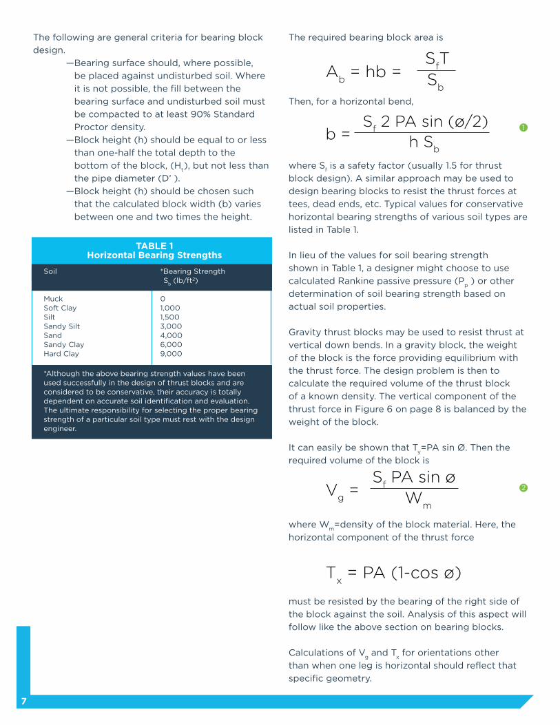
The following are general criteria for bearing block
design.
—Bearing surface should, where possible,
be placed against undisturbed soil. Where
it is not possible, the fill between the
bearing surface and undisturbed soil must
be compacted to at least 90% Standard
Proctor density.
—Block height (h) should be equal to or less
than one-half the total depth to the
bottom of the block, (Ht), but not less than
the pipe diameter (D’ ).
—Block height (h) should be chosen such
that the calculated block width (b) varies
between one and two times the height.
The required bearing block area is
Then, for a horizontal bend,
where Sf is a safety factor (usually 1.5 for thrust
block design). A similar approach may be used to
design bearing blocks to resist the thrust forces at
tees, dead ends, etc. Typical values for conservative
horizontal bearing strengths of various soil types are
listed in Table 1.
In lieu of the values for soil bearing strength
shown in Table 1, a designer might choose to use
calculated Rankine passive pressure (Pp ) or other
determination of soil bearing strength based on
actual soil properties.
Gravity thrust blocks may be used to resist thrust at
vertical down bends. In a gravity block, the weight
of the block is the force providing equilibrium with
the thrust force. The design problem is then to
calculate the required volume of the thrust block
of a known density. The vertical component of the
thrust force in Figure 6 on page 8 is balanced by the
weight of the block.
It can easily be shown that Ty=PA sin Ø. Then the
required volume of the block is
where Wm=density of the block material. Here, the
horizontal component of the thrust force
must be resisted by the bearing of the right side of
the block against the soil. Analysis of this aspect will
follow like the above section on bearing blocks.
Calculations of Vg and T
x for orientations other
than when one leg is horizontal should reflect that
specific geometry.
7
TABLE 1Horizontal Bearing Strengths
Soil
MuckSoft ClaySiltSandy SiltSandSandy ClayHard Clay
*Although the above bearing strength values have been used successfully in the design of thrust blocks and are considered to be conservative, their accuracy is totally dependent on accurate soil identification and evaluation. The ultimate responsibility for selecting the proper bearing strength of a particular soil type must rest with the design engineer.
*Bearing Strength S
b (lb/ft2)
01,0001,5003,0004,0006,0009,000
Ab = hb =
SfT
Sb
Vg =
Sf PA sin ø
Wm
Tx = PA (1-cos ø)
b = S
f 2 PA sin (ø/2)
h Sb
1
2

Restrained Joints
An alternative method of providing thrust restraint
is the use of restrained joints. A restrained joint is a
special type of push-on or mechanical joint that is
designed to provide longitudinal restraint. Restrained
joint systems function in a manner similar to
thrust blocks, insofar as the reaction of the entire
restrained unit of piping with the soil balances the
thrust forces.
The objective in designing a restrained joint thrust
restraint system is to determine the length of pipe
that must be restrained on each side of the focus of
a thrust force. This will be a function of the pipe
size, the internal pressure, depth of cover, the
characteristics of the soil surrounding the pipe, and
whether the pipe is polyethylene encased. The
following is a method of accomplishing the design
objective. As with most engineering problems, the
exact nature of the interaction of the restrained pipe
unit and the soil is extremely complex. Limitations
of the ability to measure the actual parameters
involved and limitations on available knowledge of
the precise nature of the interaction require that a
practical design procedure be based on various
assumptions. The assumptions employed in the
following design procedure are, in each case,
conservative. This fact, together with the explicit
safety factor employed in the procedure, results in a
conservative design with an adequate overall safety
factor.
The proposed design equation for horizontal
bends (Equation 3, page 8) and the suggested soil
parameters (Table 2, page 12) are the outgrowth of a
design procedure originally proposed by Carlsen.1
Carlsen’s design procedure was based solely on
theoretical considerations and was conservatively
limited to well-compacted trench conditions.
The modification of Carlsen’s design procedure
embodied herein is the result of full scale tests of
12-inch Ductile Iron Pipe with 45° and 90° bends
buried in clay.2 The data generated by these tests
and data available from model studies with 2-inch
pipe in sand3 confirm the conservatism of the
present design procedure. Future work in this field
should be devoted to large-diameter piping systems,
with the objective of further confirming this
conservatism.
8
FIGURE 6
Gravity Thrust Block

which includes safety factors, is a practical and
conservative general thrust restraint design that has
been verified by available test data and numerous
installed systems.
The bearing resistance is shown as a distributed
force with a maximum unit value of Rs at the bend,
diminishing linearly to 0 at L. This assumption is
based on the fact that the bearing resistance
(passive resistance in the soil) is proportional to
deformation or movement. As the restrained joints
take load, maximum movement will occur at the
bend. The total assumed bearing resistance on each
side of the bend is 1/2RsL cos (Ø/2).
The equilibrium equation for the free body is then
Employing a safety factor and solving for L,
Sf = Safety factor (Usually 1.5)
9
The thrust force must be restrained or balanced
by the reaction of the restrained pipe unit with the
surrounding soil. The source of the restraining forces
is twofold: first, the static friction between the pipe
unit and the soil, and second, the restraint provided
by the pipe as it bears against the sidefill soil along
each leg of the bend. Both of these forces are
presumed to be functions of the restrained length L
on each side of the bend and they are presumed to
act in the direction opposing the thrust force (i.e.,
directly opposing impending movement of the bend).
Horizontal Bends (Figure 7)
Figure 7 is a free body diagram of a restrained pipe
unit where L is the length of the restrained pipe on
each side of the bend. The unit frictional resistance
is shown as a distributed force of unit value Ff. The
total frictional resistance on each side of the bend is
then FfL cos (Ø/2).
It is not purported that Figure 7 represents the
actual pipe-soil behavior with all trench types and
the various restrained joint designs available.
Variations in the way different restrained joints
respond to loadings, along with soil and installation
variables, make this a situation which defies precise
theoretical representation. The approach presented,
FIGURE 7*
Horizontal Bend
PA sin (Ø/2) = F
fL cos (Ø/2) + 1/2R
sL cos (Ø/2)
L = S
f PA tan (Ø/2)
Ff + 1/2R
s
*Free body diagram also applies to vertical up bend.
Ff = F
s; For standard asphaltic coated pipe
Ff = 0.7 F
s; For polyethylene encased pipe
3

for tee branches, dead end conditions and
reducers:
(Fs)
b = πD' C + (2W
e + W
p + W
w) tan δ
Extraordinary installations might result in lesser
loads and frictional resistance on the pipes than
that calculated by these equations and as shown in
Figure 7. When such conditions exist, this must be
provided for in the design.
Polyethylene Encasement
Limited experimental data suggest that the frictional
resistance terms (Fs ) and (F
s )
b should be multiplied
by a factor of 0.70 for pipe encased in polyethylene
film to determine the appropriate value of Ff to use
in the equations.
10
Unit Frictional Force, Fs
A static frictional force acting on a body is equal in
magnitude to the applied force up to a maximum
value. In the conventional analysis, the maximum
static friction is proportional to the normal force
between the surfaces which provide the friction.
The constant of proportionality, in this case called
the coefficient of friction, depends upon the nature
of the surfaces. Potyondy’s empirical work indicates
that for friction between pipe and soils, the force is
also dependent upon the cohesion of the soil.4
Thus
Fs=A
pC + W tan δ
where
C = fcC
s
Ap
= surface area of the pipe bearing on the soil
δ = fφφ A
p = πD′ (for bends, assume 1/2 the 2 pipe
2 circumference bears against the soil)
= πD′ (for tree branches, dead end conditions,
and reducers, assume the full pipe
circumference bears against the soil)
Values of soil cohesion (Cs) and internal
friction angle of the soil (φ) must be known or
conservatively estimated for the soil at a particular
installation. fc and fφ are related to soil types and
pipe material. Table 3 presents conservative values
of these parameters for Ductile Iron Pipe in seven
general classifications of saturated soils.
The unit normal force W is given by
W = 2 We + W
p + W
w
where the earth load (We) is taken as the prism load
on the pipe in pounds. The earth load is doubled
to account for the forces acting on both the top
and the bottom of the pipe (see Figure 8). The unit
weight of the pipe and water (Wp + W
w) is given in
Table 2 on page 12.
Then
for bends:
Fs = πD' C + (2W
e + W
p + W
w) tan δ
2 4a
FIGURE 8
Unit Normal Forces On Pipe
4b
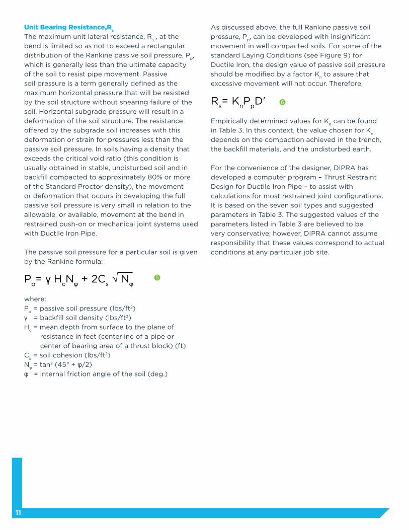
As discussed above, the full Rankine passive soil
pressure, Pp, can be developed with insignificant
movement in well compacted soils. For some of the
standard Laying Conditions (see Figure 9) for
Ductile Iron, the design value of passive soil pressure
should be modified by a factor Kn to assure that
excessive movement will not occur. Therefore,
Rs= K
nP
pD'
Empirically determined values for Kn can be found
in Table 3. In this context, the value chosen for Kn
depends on the compaction achieved in the trench,
the backfill materials, and the undisturbed earth.
For the convenience of the designer, DIPRA has
developed a computer program – Thrust Restraint
Design for Ductile Iron Pipe – to assist with
calculations for most restrained joint configurations.
It is based on the seven soil types and suggested
parameters in Table 3. The suggested values of the
parameters listed in Table 3 are believed to be
very conservative; however, DIPRA cannot assume
responsibility that these values correspond to actual
conditions at any particular job site.
11
Unit Bearing Resistance,Rs
The maximum unit lateral resistance, Rs , at the
bend is limited so as not to exceed a rectangular
distribution of the Rankine passive soil pressure, Pp,
which is generally less than the ultimate capacity
of the soil to resist pipe movement. Passive
soil pressure is a term generally defined as the
maximum horizontal pressure that will be resisted
by the soil structure without shearing failure of the
soil. Horizontal subgrade pressure will result in a
deformation of the soil structure. The resistance
offered by the subgrade soil increases with this
deformation or strain for pressures less than the
passive soil pressure. In soils having a density that
exceeds the critical void ratio (this condition is
usually obtained in stable, undisturbed soil and in
backfill compacted to approximately 80% or more
of the Standard Proctor density), the movement
or deformation that occurs in developing the full
passive soil pressure is very small in relation to the
allowable, or available, movement at the bend in
restrained push-on or mechanical joint systems used
with Ductile Iron Pipe.
The passive soil pressure for a particular soil is given
by the Rankine formula:
Pp= γ H
cNφ + 2C
s √ Nφ
where:
Pp
= passive soil pressure (lbs/ft2)
γ = backfill soil density (lbs/ft3)
Hc
= mean depth from surface to the plane of
resistance in feet (centerline of a pipe or
center of bearing area of a thrust block) (ft)
Cs
= soil cohesion (lbs/ft2)
Nφ = tan2 (45° + φ/2)
φ = internal friction angle of the soil (deg.)
5
6

12
TABLE 2Dimensions and Unit Weights of Pipe and Water
NominalPipe Size (in)
3
4
6
8
10
12
14
16
18
20
24
30
36
42
48
54
60
64
PressureClass
350
350
350
350
350
350
250
250
250
250
200
150
150
150
150
150
150
150
Pipe OutsideDiameter, D’ (ft)
0.33
0.40
0.58
0.75
0.93
1.10
1.28
1.45
1.63
1.80
2.15
2.67
3.19
3.71
4.23
4.80
5.13
5.47
Cross-sectionalArea of Pipe, A (in2)
12.3
18.1
37.3
64.3
96.7
136.8
183.8
237.7
298.6
366.4
522.7
804.2
1152.0
1555.2
2026.8
2602.1
2981.2
3387.0
Wp (lbs/ft)
10
12
18
24
30
39
47
57
66
78
93
123
163
206
261
325
371
410
Ww (lbs/ft)
4
6
13
24
37
53
72
94
119
147
212
329
473
642
838
1078
1237
1407
Wp + W
w*
(lbs/ft)
14
18
31
48
67
92
119
151
185
225
305
452
636
848
1099
1403
1608
1817
*Based on minimum pressure class pipe with standard cement-mortar lining. The difference in Wp + W
w for other pipe pressure
classes is not normally significant in relation to these calculations and these values may be used conservatively regardless of pipepressure class. However, the designer may use actual pipe weights for optimum design if desired.
Type 1*
Flat-bottom trench.†
Loose backfill.
Type 3
Pipe bedded in
4-inch minimum
loose soil.‡ Backfill
lightly consolidated
to top of pipe.
Type 2
Flat-bottom trench.†
Backfill lightly
consolidated to
centerline of pipe.
Type 4
Pipe bedded in sand,
gravel, or crushed
stone to depth of
1/8 pipe diameter,
4-inch minimum.
Backfill compacted
to top of pipe.
(Approximately
80% Standard
Proctor, AASHTO
T-99.)§ (See
Table 1 for notes.)
Type 5
Pipe bedded to
its centerline in
compacted granular
material,** 4-inch
minimum under
pipe. Compacted
granular or
select‡ material
to top of pipe.
(Approximately 90%
Standard Proctor,
AASHTO T-99.)§
FIGURE 9
Standard ANSI/AWWA C150/A21.50 Laying Conditions for Ductile Iron Pipe
* For 14-inch and larger pipe, consideration should be given to the use of laying conditions other than Type 1.† “Flat-bottom” is defined as “undisturbed earth.”‡ “Loose soil” or “select material” is defined as “native soil excavated from the trench, free of rocks, foreign material, and frozen earth.”†† AASHTO T-99 “Standard Method of Test for the Moisture-Density Relations of Soils Using a 5.5 lb (2.5 kg) Rammer and a 12 in. (305 mm) Drop.” Available from the American Association of State Highway and Transportation Officials.** Granular materials are defined per the AASHTO Soil Classification System (ASTM D3282) or the Unified Soil Classification System (ASTM D2487), with the exception that gravel bedding/backfill adjacent to the pipe is limited to 2” maximum particle size per ANSI/AWWA C600.
13
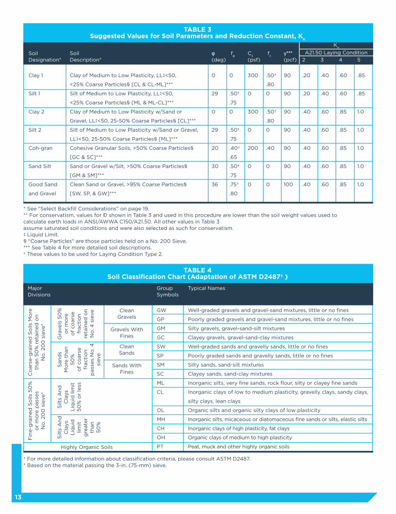
TABLE 3Suggested Values for Soil Parameters and Reduction Constant, K
n
SoilDesignation*
Clay 1
Silt 1
Clay 2
Silt 2
Coh-gran
Sand Silt
Good Sand
and Gravel
SoilDescription*
Clay of Medium to Low Plasticity, LL‡<50,
<25% Coarse Particles§ [CL & CL-ML]***
Silt of Medium to Low Plasticity, LL‡<50,
<25% Coarse Particles§ [ML & ML-CL]***
Clay of Medium to Low Plasticity w/Sand or
Gravel, LL‡<50, 25-50% Coarse Particles§ [CL]***
Silt of Medium to Low Plasticity w/Sand or Gravel,
LL‡<50, 25-50% Coarse Particles§ [ML]***
Cohesive Granular Soils, >50% Coarse Particles§
[GC & SC]***
Sand or Gravel w/Silt, >50% Coarse Particles§
[GM & SM]***
Clean Sand or Gravel, >95% Coarse Particles§
[SW, SP, & GW]***
φ(deg)
0
29
0
29
20
30
36
γ***(pcf)
90
90
90
90
90
90
100
Cs
(psf)
300
0
300
0
200
0
0
3
.40
.40
.60
.60
.60
.60
.60
fφ
0
.50†
.75
0
.50†
.75
.40†
.65
.50†
.75
.75†
.80
2
.20
.20
.40
.40
.40
.40
.40
fc
.50†
.80
0
.50†
.80
0
.40
0
0
4
.60
.60
.85
.85
.85
.85
.85
5
.85
.85
1.0
1.0
1.0
1.0
1.0
* See “Select Backfill Considerations” on page 19.** For conservatism, values for γ shown in Table 3 and used in this procedure are lower than the soil weight values used to calculate earth loads in ANSI/AWWA C150/A21.50. All other values in Table 3assume saturated soil conditions and were also selected as such for conservatism.‡ Liquid Limit.§ “Coarse Particles” are those particles held on a No. 200 Sieve.*** See Table 4 for more detailed soil descriptions.† These values to be used for Laying Condition Type 2.
† For more detailed information about classification criteria, please consult ASTM D2487.* Based on the material passing the 3-in. (75-mm) sieve.
TABLE 4Soil Classification Chart (Adaptation of ASTM D2487† )
Major Divisions
Group Symbols
GW
GP
GM
GC
SW
SP
SM
SC
ML
CL
OL
MH
CH
OH
PT
Typical Names
Well-graded gravels and gravel-sand mixtures, little or no fines
Poorly graded gravels and gravel-sand mixtures, little or no fines
Silty gravels, gravel-sand-silt mixtures
Clayey gravels, gravel-sand-clay mixtures
Well-graded sands and gravelly sands, little or no fines
Poorly graded sands and gravelly sands, little or no fines
Silty sands, sand-silt mixtures
Clayey sands, sand-clay mixtures
Inorganic silts, very fine sands, rock flour, silty or clayey fine sands
Inorganic clays of low to medium plasticity, gravelly clays, sandy clays,
silty clays, lean clays
Organic silts and organic silty clays of low plasticity
Inorganic silts, micaceous or diatomaceous fine sands or silts, elastic silts
Inorganic clays of high plasticity, fat clays
Organic clays of medium to high plasticity
Peat, muck and other highly organic soils
A21.50 Laying Condition
Kn
Co
ars
e-g
rain
ed
So
ils M
ore
th
an
50
% r
eta
ined
on
N
o. 20
0 s
ieve*
Fin
e-g
rain
ed
So
ils 5
0%
o
r m
ore
pass
es
No
. 20
0 s
ieve*
Gra
vels
50
%
or
mo
re
of
co
ars
e
fracti
on
re
tain
ed
on
N
o. 4
sie
ve
Gravels WithFines
Sands WithFines
CleanGravels
Highly Organic Soils
CleanSands
San
ds
Mo
re t
han
5
0%
of
co
ars
e
fracti
on
pass
es
No
. 4
si
eve
Silt
s A
nd
Cla
ys
Liq
uid
lim
it5
0%
or
less
Silt
s A
nd
Cla
ys
Liq
uid
lim
itg
reate
r th
an
50
%
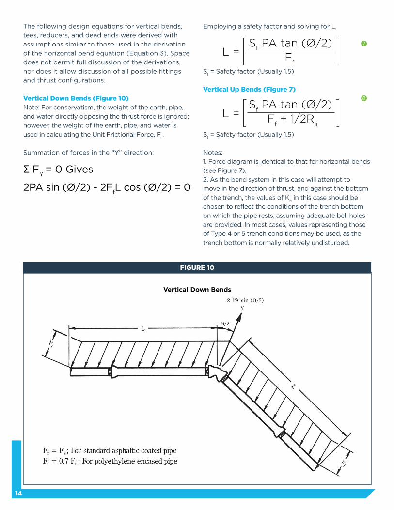
The following design equations for vertical bends,
tees, reducers, and dead ends were derived with
assumptions similar to those used in the derivation
of the horizontal bend equation (Equation 3). Space
does not permit full discussion of the derivations,
nor does it allow discussion of all possible fittings
and thrust configurations.
Vertical Down Bends (Figure 10)
Note: For conservatism, the weight of the earth, pipe,
and water directly opposing the thrust force is ignored;
however, the weight of the earth, pipe, and water is
used in calculating the Unit Frictional Force, Fs.
Summation of forces in the “Y” direction:
Σ FY = 0 Gives
2PA sin (Ø/2) - 2FfL cos (Ø/2) = 0
Employing a safety factor and solving for L,
Sf = Safety factor (Usually 1.5)
Vertical Up Bends (Figure 7)
Sf = Safety factor (Usually 1.5)
Notes:
1. Force diagram is identical to that for horizontal bends
(see Figure 7).
2. As the bend system in this case will attempt to
move in the direction of thrust, and against the bottom
of the trench, the values of Kn in this case should be
chosen to reflect the conditions of the trench bottom
on which the pipe rests, assuming adequate bell holes
are provided. In most cases, values representing those
of Type 4 or 5 trench conditions may be used, as the
trench bottom is normally relatively undisturbed.
14
FIGURE 10
Vertical Down Bends
7
8
L = S
f PA tan (Ø/2)
Ff
L = S
f PA tan (Ø/2)
Ff + 1/2R
s
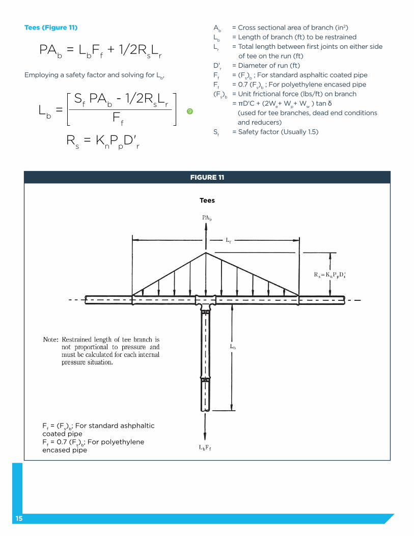
Tees (Figure 11)
Employing a safety factor and solving for Lb,
15
FIGURE 11
Tees
PAb = L
bF
f + 1/2R
sL
r
Lb =
Rs = K
nP
pD'
r
Ff
Sf PA
b - 1/2R
sL
r
Ab = Cross sectional area of branch (in2)
Lb = Length of branch (ft) to be restrained
Lr = Total length between first joints on either side
of tee on the run (ft)
D'r = Diameter of run (ft)
Ff = (F
s)
b ; For standard asphaltic coated pipe
Ff = 0.7 (F
s)
b ; For polyethylene encased pipe
(Fs)
b = Unit frictional force (lbs/ft) on branch
= πD'C + (2We+ W
p+ W
w ) tan δ
(used for tee branches, dead end conditions
and reducers)
Sf = Safety factor (Usually 1.5)
Ff = (F
s)
b; For standard ashphaltic
coated pipeF
f = 0.7 (F
s)
b; For polyethylene
encased pipe
9
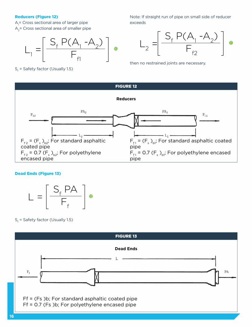
Reducers (Figure 12)
A1= Cross sectional area of larger pipe
A2= Cross sectional area of smaller pipe
Sf = Safety factor (Usually 1.5)
Dead Ends (Figure 13)
Sf = Safety factor (Usually 1.5)
Note: If straight run of pipe on small side of reducer
exceeds
then no restrained joints are necessary.
16
L1 =
Sf P(A
1 -A
2)
Ff1
L = S
f PAF
f
L2 =
Sf P(A
1 -A
2)
Ff2
FIGURE 12
Reducers
FIGURE 13
Dead Ends
Ff 2
= (Fs )
b2; For standard asphaltic
coated pipeF
f 2 = 0.7 (F
s )
b2; For polyethylene
encased pipe
Ff 1 = (F
s )
b1; For standard asphaltic coated
pipeF
f 1 = 0.7 (F
s )
b1; For polyethylene encased
pipe
Ff = (Fs )b; For standard asphaltic coated pipeFf = 0.7 (Fs )b; For polyethylene encased pipe
10
12
11

Encroaching Restrained Lengths
Both horizontal and vertical offsets are commonly
encountered in restrained sections of a line. These
offsets should be made with as small a degree bend
as possible in order to minimize the thrust loads and
restrained length required. Also, in these configurations
an increase in line segment length could be detrimental
to the pipeline or surrounding structures due to
over-deflection of the joints; therefore, the restrained
joints should be fully extended (if applicable) during
installation.
In certain configurations, fittings may be close enough
to one another that adjacent calculated restrained
lengths overlap. In situations of this type, one approach
is to:
1) Restrain all pipe between the two fittings
2) Assume 1/2 of the restrained pipe length between
the two fittings acts to resist the thrust force of each
fitting and
3) Using the appropriate equations, calculate the
additional restrained length required on the outer legs
of the fittings.
Following are two such examples:
Equal Angle Vertical Offset (Ø°)* (Figure 14)
For L1:
Σ F = 0
[2PA sin (Ø/2)] = [FfL cos (Ø/2)] +
[FfL
1 cos (Ø/2)]
Employing a safety factor and solving for L1,
For L2:
Σ F = 0
[2PA sin (Ø/2)] = [FfL cos (Ø/2)] +
[1/2RsL cos (Ø/2)] +
[FfL
2 cos (Ø/2)] +
[1/2RsL
2 cos (Ø/2)]
Employing a safety factor and solving for L2,
Sf = Safety factor (Usually 1.5)
17
FIGURE 14
Equal Angle Vertical Offset (θ°)*
L = - LS
f 2PA tan (Ø/2)
Ff
L = - LS
f 2PA tan (Ø/2)
Ff + 1/2R
s
* As the bend angle approaches 90º, lateral movement of the outer legs approaches zero. For this condition, restrain all pipe between the fittings and restrain the outer legs as dead ends.
13
14
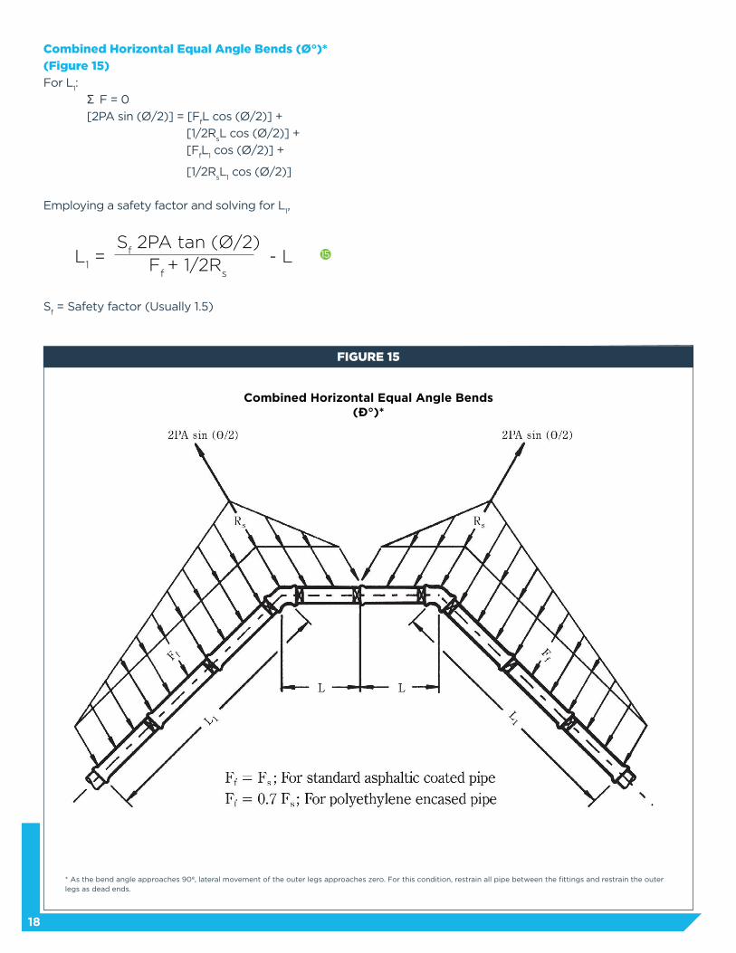
Combined Horizontal Equal Angle Bends (Ø°)*
(Figure 15)
For L1:
Σ F = 0
[2PA sin (Ø/2)] = [FfL cos (Ø/2)] +
[1/2RsL cos (Ø/2)] +
[FfL
1 cos (Ø/2)] +
[1/2RsL
1 cos (Ø/2)]
Employing a safety factor and solving for L1,
Sf = Safety factor (Usually 1.5)
18
FIGURE 15
Combined Horizontal Equal Angle Bends (θ°)*
L1 = - L
Sf 2PA tan (Ø/2)
Ff + 1/2R
s
* As the bend angle approaches 90º, lateral movement of the outer legs approaches zero. For this condition, restrain all pipe between the fittings and restrain the outer legs as dead ends.
15

1) Restrain all pipe between the outermost two fittings
2) Due to opposing forces, the thrust forces of
the middle two fittings (vertical up bends) are
counteracted
3) Assume 1/2 of the restrained pipe length between
the vertical down and vertical up bends acts to resist
the thrust force of the vertical down bends and
4) Using the appropriate equations, calculate the
additional restrained length required on the outermost
legs of the offset system (vertical down bends). The
resulting equation is the same as for the vertical down
bend in the single vertical offset (Equation 13):
Sf = Safety factor (Usually 1.5)
Combined Vertical Equal Angle Offsets (Ø°)* –
Under Obstruction (Figure 16)
Vertical offsets are often combined to route a pipeline
under an obstruction or existing utility. If the required
restrained lengths of the vertical up bends do not
overlap, the system may be treated as two individual
vertical offsets (Figure 14). If the required restrained
lengths do overlap, one approach is to:
19
FIGURE 16
Combined Vertical Equal Angle Offsets (θ°)*
L1 = - L
Sf 2PA tan (Ø/2)
Ff 16
Combined Vertical Equal Angle Offsets (Ø°)* –
Over Obstruction
This can be analyzed in the same manner as Figure 16
with the following equation:
Sf = Safety factor (Usually 1.5)
Note: This equation also applies to combined horizontal
equal angle offsets (Ø°) – around an obstruction.
L1 = - L
Sf 2PA tan (Ø/2)
Ff + 1/2R
s 17
* As the bend angle approaches 90º, lateral movement of the outer legs approaches zero. For this condition, restrain all pipe between the fittings and restrain the outer legs as dead ends.
Restrained Length
In practice, the actual restrained length attained will
generally be in multiples of length of an individual piece
of pipe (normally 18 or 20 feet). The length calculated
indicates the minimum required restrained length for
each side of the bend. Thus, calculated lengths of 0 to
18 or 20 feet normally call for one restrained joint at the
fitting, 18 to 36 or 20 to 40 feet normally require two
restrained joints, etc.
Select Backfill Considerations
If restrained joint pipe is laid in trench backfill with
markedly different support characteristics than the
native soil, special considerations may be required. As
the pipe is pressurized, it will transmit passive pressure
to the backfill that will in turn transmit this pressure to
the native soil. Therefore, the material that results in the
smaller unit bearing resistance (Rs) should be used for
the passive resistance and the unit friction force (Fs)
should be based on the backfill material surrounding
the pipe.
If restrained joints are used in swamps or marshes
where the soil is unstable, or in other situations where
the bearing strength of the soil is extremely poor,
the entire pipeline should be restrained to provide
adequate thrust restraint.
Combining Thrust Blocks and Restrained Joints
Combining restrained joints and thrust blocks by
designing each system independently of the other and
then incorporating both to the piping system normally
yields the greatest degree of security. It is often poor
practice to mix systems based on each system being
designed to resist a percentage of the resultant thrust
force. Both thrust blocks and restrained joint
pipe systems require slight movement before
their respective thrust restraint capability can be
developed. Those movements must be compatible
for the combination to be successful. Because of the
uncertainties of the degree of these movements being
compatible, this design approach must be given special
consideration.
Pipe in a Casing
It is often necessary to install restrained joint pipe
through a casing pipe. The function of restrained joint
pipe is basically to transfer thrust forces to the soil
structure. Therefore, if the annular space between the
two pipes is not grouted in, the length of restrained
pipe inside the casing should not be considered as part
of the restrained length to balance the thrust force.
When restrained joint pipe is installed through a
casing pipe, the restrained joints should normally be
fully extended.
Future Excavations
One particular concern of those with responsibility
for infrastructure pipeline design, installation, and
maintenance is the possibility of substantial excavation
in the close vicinity of previously installed restrained
pipe and fittings including parallel excavations.
Remembering the usual function of restrained pipes
in transmitting thrust forces to the soil structure, it is
obvious that if this structure is removed or significantly
disturbed with the pipeline under pressure, the safety
and stability of the system may be compromised. In this
regard, it would seem reasonable to temporarily shut
down close existing restrained lines to do such work, or
to conduct such operations during lowest pressure
service conditions. Where this is not practical or
possible, alternate provisions might be safely employed.
These precautions might include supplementary thrust
blocking, restraint with laterally loaded piles or batter
piles at the thrust focus, special pipe anchors, or other
careful, sequential, and innovative engineering and
construction procedures. Proper engineering and
construction judgment must be exercised in these
conditions.2
Deflected Unrestrained Ductile Iron Pipe Joints
Unrestrained push-on and mechanical joint Ductile Iron
Pipe are capable of deflections up to 8° (depending on
joint type and pipe size). These joints are well-suited for
diverting pipelines from obstructions or when following
the curvature of streets and roads. In an effort to keep
thrust forces to a minimum, joint deflections should
be utilized whenever possible rather than fittings In
pressurized systems — thrust forces develop at these
joint deflections. In the vast majority of installations
the soil-pipe interaction will result in reasonable
security and stability of the joints. Only in extraordinary
circumstances, e.g., unstable soils, high internal pressure
in combination with very shallow cover, etc., is the
security threatened. In these situations, soil-pipe thrust
resisting principles, not unlike those presented in this
manual, may be applied to these unrestrained joint
situations.
20
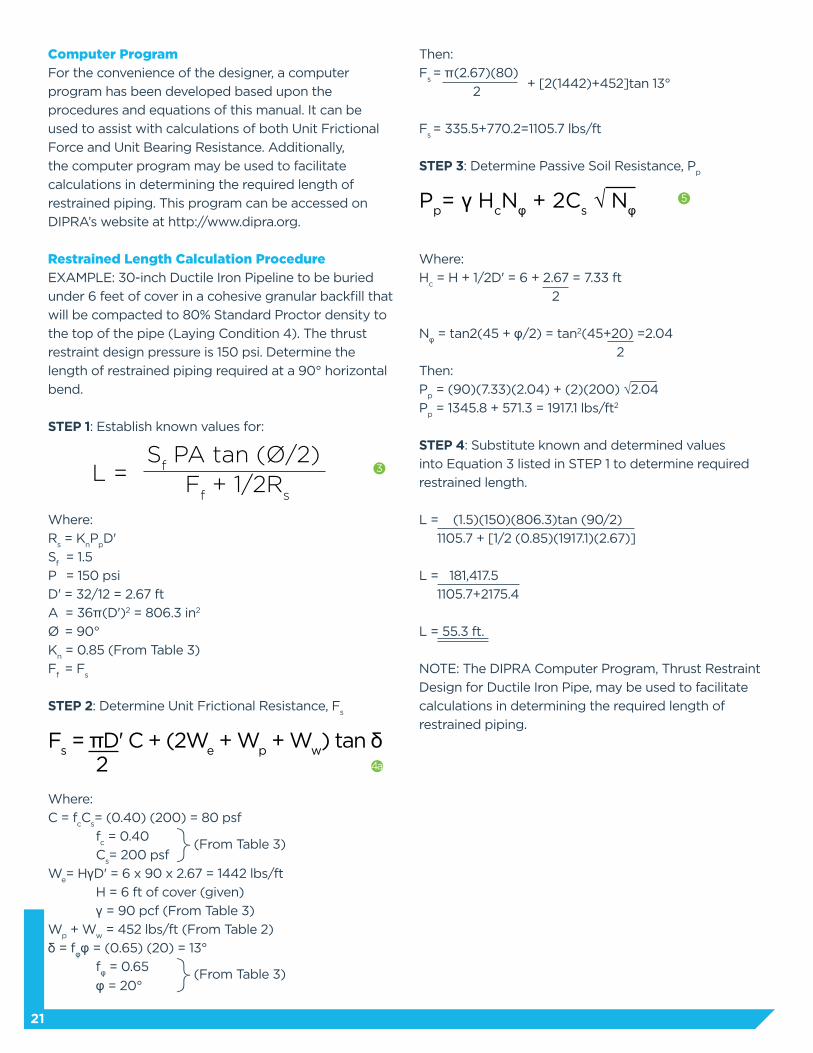
Then:
Fs = π(2.67)(80)
2 + [2(1442)+452]tan 13°
Fs = 335.5+770.2=1105.7 lbs/ft
STEP 3: Determine Passive Soil Resistance, Pp
Pp= γ H
cNφ + 2C
s √ Nφ
Where:
Hc = H + 1/2D' = 6 + 2.67 = 7.33 ft
2
Nφ = tan2(45 + φ/2) = tan2(45+20) =2.04
2
Then:
Pp = (90)(7.33)(2.04) + (2)(200) √2.04
Pp = 1345.8 + 571.3 = 1917.1 lbs/ft2
STEP 4: Substitute known and determined values
into Equation 3 listed in STEP 1 to determine required
restrained length.
L = (1.5)(150)(806.3)tan (90/2)
1105.7 + [1/2 (0.85)(1917.1)(2.67)]
L = 181,417.5
1105.7+2175.4
L = 55.3 ft.
NOTE: The DIPRA Computer Program, Thrust Restraint
Design for Ductile Iron Pipe, may be used to facilitate
calculations in determining the required length of
restrained piping.
21
Computer Program
For the convenience of the designer, a computer
program has been developed based upon the
procedures and equations of this manual. It can be
used to assist with calculations of both Unit Frictional
Force and Unit Bearing Resistance. Additionally,
the computer program may be used to facilitate
calculations in determining the required length of
restrained piping. This program can be accessed on
DIPRA’s website at http://www.dipra.org.
Restrained Length Calculation Procedure
EXAMPLE: 30-inch Ductile Iron Pipeline to be buried
under 6 feet of cover in a cohesive granular backfill that
will be compacted to 80% Standard Proctor density to
the top of the pipe (Laying Condition 4). The thrust
restraint design pressure is 150 psi. Determine the
length of restrained piping required at a 90° horizontal
bend.
STEP 1: Establish known values for:
Where:
Rs = K
nP
pD'
Sf = 1.5
P = 150 psi
D' = 32/12 = 2.67 ft
A = 36π(D')2 = 806.3 in2
Ø = 90°
Kn = 0.85 (From Table 3)
Ff = F
s
STEP 2: Determine Unit Frictional Resistance, Fs
Fs = πD' C + (2W
e + W
p + W
w) tan δ
2
Where:
C = fcC
s= (0.40) (200) = 80 psf
fc = 0.40
Cs= 200 psf
We= HγD' = 6 x 90 x 2.67 = 1442 lbs/ft
H = 6 ft of cover (given)
γ = 90 pcf (From Table 3)
Wp + W
w = 452 lbs/ft (From Table 2)
δ = fφφ = (0.65) (20) = 13°
fφ = 0.65
φ = 20°
L = S
f PA tan (Ø/2)
Ff + 1/2R
s
3
4a
} (From Table 3)
} (From Table 3)
5

Nomenclature
A = Cross-sectional area of pipe (inch2) = 36π D' 2
(See Table 2)
Ap = Surface area of pipe exterior (ft2/ft)
b = Thrust block width (ft)
C = Pipe cohesion (lbs/ft2)
Cs = Soil cohesion (lbs/ft2) (See Table 3)
D' = Outside diameter of pipe (ft) (See Table 2)
fc = Ratio of pipe cohesion to soil cohesion
(See Table 3)
Ff
= Unit frictional resistance (lbs/ft)
Fs = Unit frictional force assuming 1/2 the pipe
circumference bears against the soil (lbs/ft)
(Fs)
b = Unit frictional force assuming the entire pipe
circumference contacts the soil (lbs/ft)
fφ = Ratio of pipe friction angle to soil friction
angle (See Table 3)
h = Thrust block height (ft)
H = Depth of cover to top of pipe (ft)
Hc = Depth of cover to pipe centerline (ft)
Ht = Depth to bottom of thrust block (ft)
Kn = Trench condition modifier (See Table 3)
L = Minimum required restrained pipe length (ft)
Nφ = tan2 (45° + φ/2)
P = Design pressure (psi)
Pp = Passive soil pressure (lbs/ft2)
Rs = Unit bearing resistance (lbs/ft)
Sb = Horizontal bearing strength of soil (lbs/ft2 )
(See Table 1)
T = Resultant thrust force (lbs)
γ = Backfill soil density (lbs/ft3) (See Table 3)
W = Unit normal force on pipe
= 2 We + W
p + W
w (lbs/ft)
We = Earth prism load (lbs/ft) = γHD'
Wm = Density of thrust block material (lbs/ft3)
Wp = Unit weight of pipe (lbs/ft) (See Table 2)
Ww = Unit weight of water (lbs/ft) (See Table 2)
Ø = Bend angle (degrees)
δ = Pipe friction angle (degrees)
φ = Soil internal friction angle (degrees)
(See Table 3)
Sf = Safety factor (usually 1. 5)
Vg = Volume of thrust block (ft3)
References
1. Carlsen, R.J., “Thrust Restraint for Underground Piping
Systems.” Cast Iron Pipe News, Fall 1975.
2. Conner, R.C. “Thrust Restraint of Buried Ductile
Iron Pipe,” Proceedings of Pipeline Infrastructure
Conference, Boston, Massachusetts, June 6-7, 1988.
Published by ASCE, New York, NY, 1988, p. 218.
3. Reference U.S. Pipe & Foundry Company research
(Unpublished).
4. Potyondy, J.G., M. Eng., Skin Friction Between Various
Soils and Construction Materials.
5. ASTM D 2487—Classification of Soils for Engineering
Purposes.
22

Strength and Durability for Life®
Ductile Iron Pipe Research Association
An association of quality producers dedicated to the highest pipe standards through a program of continuing research and service to water and wastewater professionals.
P.O. Box 190306 Birmingham, AL 35219 205.402.8700 Telwww.dipra.org
Social Media
Get in the flow with Ductile Iron Pipe by connecting with us on Facebook, Twitter, and LinkedIn.
Visit our website, www.dipra.org/videos, and click on the YouTube icon for informational videos on Ductile Iron Pipe’s ease of use, economic benefits, strength and durability, advantages over PVC, and more.
Copyright © 2016 by Ductile Iron Pipe Research Association
Member Companies
AMERICAN Ductile Iron PipeP.O. Box 2727Birmingham, Alabama 35202-2727
Canada Pipe Company, Ltd.55 Frid St. Unit #1Hamilton, Ontario L8P 4M3 Canada
McWane DuctileP.O. Box 6001Coshocton, Ohio 43812-6001
United States Pipe and Foundry Company Two Chase Corporate DriveSuite 200Birmingham, Alabama 35244
Ductile Iron Pipe is
For more information contact DIPRA or any of its member companies.
Copyright © 2022 FDOKUMEN