Electrohydrodynamic thrust for in-atmosphere propulsion - oatao
Upload
khangminh22Category
view
1download
0
Turbomachinery Propulsion and Power
International Journal of
Article
Differential Throttling and Fluidic Thrust Vectoring ina Linear Aerospike
Michele Ferlauto , Andrea Ferrero * , Matteo Marsicovetere and Roberto Marsilio
�����������������
Citation: Ferlauto, M.; Ferrero, A.;
Marsicovetere, M.; Marsilio, R.
Differential Throttling and Fluidic
Thrust Vectoring in a Linear
Aerospike. Int. J. Turbomach. Propuls.
Power 2021, 6, 8. https://doi.org/
10.3390/ijtpp6020008
Academic Editor: Francesco Martelli
Received: 6 February 2021
Accepted: 16 April 2021
Published: 21 April 2021
Publisher’s Note: MDPI stays neutral
with regard to jurisdictional claims in
published maps and institutional affil-
iations.
Copyright: © 2021 by the authors.
Licensee MDPI, Basel, Switzerland.
This article is an open access article
distributed under the terms and
conditions of the Creative Commons
Attribution (CC BY-NC-ND) license
(https://creativecommons.org/
licenses/by-nc-nd/4.0/).
Department of Mechanical and Aerospace Engineering, Politecnico di Torino, Corso Duca degli Abruzzi 24,10129 Torino, Italy; [email protected] (M.F.); [email protected] (M.M.);[email protected] (R.M.)* Correspondence: [email protected]
Abstract: Aerospike nozzles represent an interesting solution for Single-Stage-To-Orbit or clusteredlaunchers owing to their self-adapting capability, which can lead to better performance comparedto classical nozzles. Furthermore, they can provide thrust vectoring in several ways. a simplesolution consists of applying differential throttling when multiple combustion chambers are used.An alternative solution is represented by fluidic thrust vectoring, which requires the injectionof a secondary flow from a slot. In this work, the flow field in a linear aerospike nozzle wasinvestigated numerically and both differential throttling and fluidic thrust vectoring were studied.The flow field was predicted by solving the Reynolds-averaged Navier–Stokes equations. The thrustvectoring performance was evaluated in terms of side force generation and axial force reduction.The effectiveness of fluidic thrust vectoring was investigated by changing the mass flow rate ofsecondary flow and injection location. The results show that the response of the system can benon-monotone with respect to the mass flow rate of the secondary injection. In contrast, differentialthrottling provides a linear behaviour but it can only be applied to configurations with multiplecombustion chambers. Finally, the effects of different plug truncation levels are discussed.
Keywords: aerospike; shock vectoring; differential throttling
1. Introduction
Rocket engines that are used in space launchers are usually equipped with a conven-tional fixed geometry bell-shaped nozzle which provide good performance and are quitereliable. In serially staged launchers, the area expansion ratio of the nozzles used in thedifferent stages increases significantly from the first stage to the last stage: this allows opera-tion with nearly optimum expansion ratios in the different phases of the mission. However,there are clustered launchers in which there is a core engine which works from sea-level toalmost vacuum conditions, such as the Vulcain 2 engine in the Ariane 5 launcher or theMain Engine in the Space Shuttle launching system. Furthermore, Single-Stage-to-Orbit(SSTO) configurations have been also proposed. In all these configurations, a significant per-formance gain could be obtained by reducing the non-adaptation losses: several advancednozzle concepts have been investigated for this purpose [1].
The aerospike nozzle represents an effective self-adapting nozzle which allows thenozzle exit pressure to be adapted according to the environment pressure without the use ofany moving component. Several configurations of aerospike engines have been proposedand investigated, with both circular and linear designs [2–7]. In the 1960s, Rocketdynedeveloped the J-2T-200K and J-2T-250K annular engines which were based on a toroidalcombustion chamber and a truncated plug [8]. These engines, which were derived fromthe J-2 engine used in the Saturn-family launchers, were evaluated with both cold andhot tests.
The linear aerospike engine XRS-2200 was selected as a candidate propulsion systemfor the Venture Star/X33 SSTO spaceplane in the 1990s [9]. The engine was based on
Int. J. Turbomach. Propuls. Power 2021, 6, 8. https://doi.org/10.3390/ijtpp6020008 https://www.mdpi.com/journal/ijtpp

Int. J. Turbomach. Propuls. Power 2021, 6, 8 2 of 13
a cluster of 20 independent combustion chambers and was successfully tested on theground.
After these pioneering contributions, the research effort on aerospikes slowed becauseof the cancellation of several programs. More recently, research in the field has beenled by universities and private companies. An example is the California Launch VehicleEducation Initiative (CALVEIN) as a collaboration between the California State Universityand Garvey Spacecraft Corporation. In the framework of the CALVEIN project, severaltests on a truncated plug nozzle were performed [10].
Other attempts were performed by private companies which proposed aerospikesfor the propulsion of both SSTO and Two-Stage-Two-Orbit (TSTO) configurations: FireflyAerospace and RocketStar Space proposed a TSTO vehicle, while ARCA Space Corporationproposed a SSTO design [11]. Furthermore, the use of linear aerospike nozzles has alsobeen investigated for high-speed aircrafts [12].
The development of aerospike engines is characterised by the need to solve severalchallenging aspects, from cooling issues to structural problems [1]. Furthermore, the useof an aerospike nozzle limits the possibility to perform thrust vectoring by introducinga gimballed joint, as it is done in conventional bell nozzles. This is due to the largediameter/extension of the aerospike nozzle which prevents the possibility of moving theentire nozzle. However, thrust vectoring is a key requirement for the use of aerospikenozzle in space launchers. For these reasons, several alternative thrust vectoring strategieshave been investigated [11].
Among them, some possible strategies are represented by movable plugs, flaps onthe plug, differential throttling and fluidic thrust vectoring [13–22]. Differential throttlingis a simple control strategy which can be applied in the presence of clustered aerospikeengines with multiple independent combustion chambers. Since the mass flow rate andthe pressure can be controlled independently in each chamber, it is possible to generatea lateral thrust component which can be used for manoeuvring.
However, there are both annular and linear aerospike configurations in which a com-mon combustion chamber is considered. This is particularly true for small-scale enginesin which the use of multiple chambers is not convenient [16]. In this case, differentialthrottling is no longer an option. a possible solution is represented by fluidic thrust vec-toring, which consists in injecting a secondary flow from the plug wall in order to createan obstacle for the primary flow coming from the throat. This generates a shock followedby a separation downstream to the injection point. As a consequence, an asymmetricpressure distribution is obtained on the plug wall and this generates the required lateralthrust component.
The effectiveness of the fluidic thrust vectoring is influenced by several parame-ters: injection location, injection mass flow rate, and nozzle pressure ratio. These effectshave been widely investigated experimentally [15,23,24] and numerically [15–17,23,25–29].Furthermore, fluidic thrust vectoring allows to avoid or reduce the size of aerodynamiccontrol surfaces for vehicles moving in the atmosphere [30–32]: this possibility has beeninvestigated for the development of low observable aircrafts [33]. Finally, fluidic thrustvectoring has been investigated for the development of high-performance UnmannedAerial Vehicles [34,35].
In the present work, differential throttling and fluidic thrust vectoring are discussedand compared as possible strategies for thrust control in a linear aerospike. The goal ofthe present work is to provide a cost–benefit analysis: the performance of the differentstrategies is evaluated in terms of lateral and axial force components while the requirementsare estimated in terms of mass flow rate unbalance or secondary mass flow rate. The resultswere obtained by means of numerical simulations based on the Reynolds-averaged Navier–Stokes (RANS) equations. The paper is organised as follows. In Section 2, the equationsused to evaluate the thrust components in an aerospike engine are provided. In Section 3,the physical model and the numerical schemes adopted for the simulations are described.

Int. J. Turbomach. Propuls. Power 2021, 6, 8 3 of 13
In Section 4, the numerical results are reported for two different geometries. Finally, inSection , conclusions and future perspectives are discussed.
2. Thrust Evaluation in Aerospikes
Consider the generic rocket nozzle represented in Figure 1a. The area of the exitsection of the nozzle is Ae. The thrust F generated by the rocket can be computed asfollows:
F = (Fx, Fy)T =
∫Ae(ρ(u · n)u + (p − p0)n)dA (1)
where ρ, u, p, p0 and n represent density, velocity vector, pressure, ambient pressure andnormal unit vector, respectively. According to the scheme in Figure 1a, the axis of thenozzle is assumed to be inclined with respect to the global reference system (x, y).
Consider now a linear aerospike nozzle as represented in Figure 1b: the scheme showsonly the upper half because of symmetry considerations. The previous expression can beupdated in order to compute the force in the new configuration:
F =∫
Ae(ρ(u · n)u + (p − p0)n)dA +
∫w((p − p0)I+ τ) · ndA (2)
where I represents the identity matrix and τ is the viscous stress tensor at wall. The firstintegral in Equation (2) represents the thrust of a rocket with a nozzle truncated at sectionAe. This term is augmented by the force that the fluid applies to the plug which containsboth pressure and viscous contributions: the second integral quantifies this contribution.The integrals which appear in Equation (2) must be extended to both the nozzle exits andto the full plug surface.
Plug wall
Figure 1. Scheme for the computation of the thrust component in a inclined bell nozzle (a) and in anaerospike represented by an inclined bell nozzle followed by a plug (b).
The terms in Equation (2) put in evidence the different mechanisms which can beexploited in an aerospike engine to produce a lateral thrust component Fy. When shock vec-toring is applied a fluid is injected from a slot located on one side of the plug. The injectedfluid represents an obstacle for the primary supersonic flows: this generates a shock wavewhich alters the pressure distribution. As a result, an asymmetric pressure distribution onthe two sides of the plug is obtained and the second integral in Equation (2) leads to a netlateral force component. However, the first integral in Equation (2) does contribute to thisthrust vectoring strategy because the perturbations induced by the injected fluid influenceonly the plug region and do not affect the flow field upstream to the section Ae.
An alternative strategy is exploited when differential throttling is applied. In this case,a different total pressure is imposed in the combustion chambers which feed the two sidesof the plug. As a consequence, both the integrals which appear in Equation (2) contributeto the generation of the lateral thrust component: the first integral takes into account theforce contributions generated by the region upstream to the section Ae while the secondintegral quantifies the pressure imbalance on the two sides of the plug. In the following,the mass flow rate provided by the top and bottom chambers will be referred to as mT andmB, respectively. When fluidic thrust vectoring is performed, then mT = mB and the massflow rate of the secondary injection will be referred to as mi.
Int. J. Turbomach. Propuls. Power 2021, 6, 8 4 of 13
3. Mathematical Model and Numerical Setup
The purpose of this work is to compare two different solutions for thrust vectoringin aerospike nozzles. A preliminary validation of the model and a grid convergenceanalysis was performed [21] on the results of a cold flow experimental test [1]. Since a coldflow is considered, the fluid is assumed to be air with a frozen chemical composition.This assumption is kept for all the simulations presented in this work. The flow fieldis described by means of the compressible Reynolds-averaged Navier–Stokes (RANS)equations with the Spalart–Allmaras closure model [36]. An ideal gas that follows the idealgas equation of state is assumed. The specific heat ratio is assumed to be constant and setto γ = 1.4. The dynamic viscosity is evaluated by means of the Sutherland’s law. All of thesimulations reported in the following were performed by assuming a nozzle pressure ratio(chamber total pressure over ambient static pressure) equal to 56.7. An investigation intothe effectiveness of fluidic thrust vectoring for different values of nozzle pressure ratio isreported in [21].
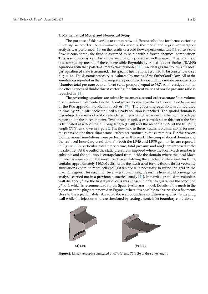
The governing equations are solved by means of a second-order accurate finite volumediscretisation implemented in the Fluent solver. Convective fluxes are evaluated by meansof the Roe approximate Riemann solver [37]. The governing equations are integratedin time by an implicit scheme until a steady solution is reached. The spatial domain isdiscretised by means of a block structured mesh, which is refined in the boundary layerregion and in the injection point. Two linear aerospikes are considered in this work: the firstis truncated at 40% of the full plug length (LP40) and the second at 75% of the full pluglength (75%), as shown in Figure 2. The flow field in these nozzles is bidimensional for mostthe extension; the three-dimensional effects are confined to the extremities. For this reason,bidimensional simulations were performed in this work. The computational domain andthe enforced boundary conditions for both the LP40 and LP75 geometries are reportedin Figure 3. In particular, total temperature, total pressure and angle are imposed at thenozzle inlet. At the outlet, the static pressure is imposed where the local Mach number issubsonic and the solution is extrapolated from inside the domain where the local Machnumber is supersonic. The mesh used for simulating the effects of differential throttlingcontains approximately 110,000 cells, while the mesh used for the fluidic thrust vectoringsimulations contains more cells (250,000) since it is necessary to refine the grid in theinjection region. This resolution level was chosen using the results from a grid convergenceanalysis carried out in a previous numerical study [21]. In particular, the dimensionlesswall distance y+ for the first layer of cells was chosen in order to guarantee the conditiony+ < 5, which is recommended for the Spalart–Allmaras model. Details of the mesh in theregion near the plug are reported in Figure 4 where it is possible to observe the refinementsclose to the injection slots. An adiabatic wall boundary condition is applied to the plugwall while the injection slots are simulated by setting a sonic inlet boundary conditions.
(a) LP40 (b) LP75
Figure 2. Linear aerospike truncated at 40% (a) and 75% (b) of the spike length.

Int. J. Turbomach. Propuls. Power 2021, 6, 8 5 of 13
(a) (b)
Figure 3. 2D computational domain for LP40 (a) and LP75 (b).
(a)
(b)
Figure 4. Detail of the mesh used for the LP40 (a) and LP75 (b).
4. Numerical Results
In this section, the numerical results obtained for the LP40 and LP75 geometries arereported for both differential throttling and shock vectoring. The performance of the twocontrol systems is evaluated in terms of lateral thrust generation and axial thrust reduction.a parametric study is performed in order to quantify the mass flow rate imbalance or thesecondary flow mass flow rate required to obtain an effective control.
4.1. Linear Aerospike Nozzle Truncated at 40% (LP40)
A first set of simulations was performed on the LP40 geometry. This configurationis characterised by a very short plug, which is representative of a real-world application:the truncation of the spike significantly reduces the cooling problems and the axial lengthof the nozzle.
Figure 5 shows the Mach field obtained on the LP40 plug using different control strate-gies. In Figure 5a, the results obtained by differential throttling are reported: this solutionis obtained by reducing the total pressure in the top chamber while keeping the same totaltemperature in both chambers. As a result, the mass flow rate from the top chamber isreduced, while the mass flow rate from the bottom chamber remains constant. In particular,the plot refers to the condition mT/mB = 0.9.

Int. J. Turbomach. Propuls. Power 2021, 6, 8 6 of 13
(a) DF, mT/mB = 0.9
(b) SVC, mi/mT = 0.1
(c) SVC, mi/mT = 0.1
Figure 5. Mach field for LP40 with differential throttling with mT/mB = 0.9 (a), SVC at x/L = 0.6with mi/mT = 0.1 (b) and SVC at x/L = 0.9 with mi/mT = 0.1 (c).
In Figure 5b, the flow field obtained by shock vector control is reported. It is pos-sible to clearly identify the location of the secondary injection on the upper side of theplug: the secondary flow acts as an obstacle which induces a shock wave as a separation.The separation moves upstream with respect to the injection slot and generates a sort offluidic ramp on the wall. The Mach field shows that the flow accelerates just downstream

Int. J. Turbomach. Propuls. Power 2021, 6, 8 7 of 13
of the injection slot and then another shock wave is generated at the end of the separationregion. These results refer to the condition mi/mT = 0.1 and the injection slot is located at60% of the plug length.
The results in Figure 5c for an injection slot located at 90% of the plug length arequalitatively similar to those observed in Figure 5b. The influence of the injection locationcan be seen more clearly by comparing the wall pressure distributions, which are reportedin Figure 6. The results show that the secondary injection generates a shock wave infront of the injection slot. The shock wave is not exactly located on the injection slot butit is placed upstream because of the boundary layer separation. An expansion regioncan be observed downstream of the injection slot. The magnitude of the lateral forcecomponent is determined by the integral of the wall pressure distribution on the full plug:the compression and the expansion regions lead to opposite contributions which tend tocancel each other out. This effect is particularly evident when the injection is located at60% of the plug length (see Figure 6a). In contrast, when the injection is performed at 90 %of the plug length, the surface affected by the expansion is reduced, as shown by Figure 6b.
(a)
(b)
Figure 6. Wall pressure distribution on LP40 with mi/mT = 0.1 with injection slot at x/L = 0.6 (a)and x/L = 0.9 (b).
These qualitative considerations are confirmed by the computations of the thrustcomponents reported in the plot of Figure 7. In particular, the lateral thrust component nor-malised with respect to the magnitude of the unperturbed thrust F0
x is shown as a functionof mi/mT in Figure 7b. When the injection is performed at 90% of the plug length, the be-haviour is monotone and the lateral thrust component is always higher with respect to theresults obtained when the injection is performed at 60% of the plug length. This seems tobe related to the fact that, when the injection is performed close to the end, the expansionacts on a small region and is not able to significantly reduce the effects generated by thecompression. This behaviour is in line with the experimental findings of [23]. Furthermore,when the injection is performed at 60% of the plug length, the results are non-monotonewith respect to mi/mT : this could again be related to the absence of a clear net effect sinceboth compression and expansion influence a significant portion of the plug.

Int. J. Turbomach. Propuls. Power 2021, 6, 8 8 of 13
0 2 4 6 8 101
1.001
1.002
1.003
1.004
1.005
1.006
Shock vect. LP40, Inject. at 60%
Shock vect. LP40, Inject. at 90%
(a)
0 2 4 6 8 100
0.002
0.004
0.006
0.008
0.01
0.012
0.014
0.016
Shock vect. LP40, Inject. at 60%
Shock vect. LP40, Inject. at 90%
(b)
Figure 7. Axial (a) and lateral (b) thrust components obtained by shock vector control onLP40 geometry.
The plot in Figure 7a shows the axial thrust component: its value is slightly in-creased when the secondary injection is introduced. This is due to the fact that the sec-ondary injection has a small axial component and this leads to a weak increase in the axialthrust component.
Finally, the results for differential throttling are reported in Figure 8: the trend in thiscase is very clear. The lateral thrust component, which is reported in Figure 8b, growslinearly with respect to (mB − mT)/mB. In this case, the axial thrust component decreasessignificantly when (mB − mT)/mB is increased. This linear behaviour can be partiallypredicted by consideration of the terms that appear in the first integral of Equation (2).The throat of the nozzles is assumed to be sonic and the total temperature is kept fixedin the two chambers. In such a condition, the mass flow rate through each nozzle isdirectly proportional to the total pressure of the chamber. Furthermore, the speed at thesection Ae is fixed because the Mach number is determined by the geometric expansionratio and the speed of sound remains constant. Finally, the static pressure at section Ae isdirectly proportional to the total pressure of the chamber because of the constant Machnumber. As a result, all of the terms that appear in the first integral of Equation (2) aredirectly proportional to the total pressure of the chamber or constants. It is not possible toperform similar analytical considerations for the second integral in Equation (2). However,the results reported in Figure 8 suggest that the linear behaviour of the terms in the firstintegral dominates the response of the system.
0 2 4 6 8 10
0.94
0.95
0.96
0.97
0.98
0.99
1
Diff. thrott. LP40
(a)
0 2 4 6 8 10
0
0.01
0.02
0.03
0.04
0.05
0.06
0.07
0.08
0.09
0.1
Diff. thrott. LP40
(b)
Figure 8. Axial (a) and lateral (b) thrust components obtained by differential throttling onLP40 geometry.
4.2. Aerospike Nozzle Truncated at 75% (LP75)
A second set of simulations was performed on the aerospike nozzle truncated at75% of the original spike length (LP75). The Mach field obtained by adopting differentialthrottling, secondary injection at 60% of the plug length and secondary injection at 90% ofthe plug length is reported in Figure 9. The results are qualitatively similar to the fieldsobtained for the LP40 but now the injection-induced separation is even more intense and

Int. J. Turbomach. Propuls. Power 2021, 6, 8 9 of 13
it covers a larger region with respect to that for the LP40: this could be related to the factthat the injection in the LP75 is applied in a region where the wall slope is smaller withrespect to the corresponding points in the LP40. a smaller wall slope is related to a smallerpressure gradient: this can influence the extension of the separation.
(a) DF, mT/mB = 0.9
(b) SVC, mi/mT = 0.1
(c) SVC, mi/mT = 0.1
Figure 9. Mach field for LP75 with differential throttling with mT/mB = 0.9 (a), SVC at x/L = 0.6with mi/mT (b) and SVC at x/L = 0.9 with mi/mT = 0.1 (c).
The wall pressure distribution obtained by using shock vector control on the LP75is reported in Figure 10. The plot confirms that the extension of the separation regionis significantly larger with respect to the LP40 since the shock is positioned significantlyupstream of the injection slot. This suggests that thrust vector control on the LP75 shouldbe more effective with respect to the LP40 configuration. This is confirmed by the plot inFigure 11b, which shows the lateral thrust component as a function of mi/mT . The valuesobserved in this configuration are larger with respect to the values obtained for the LP40:
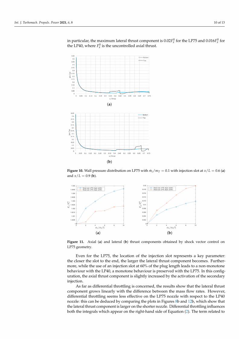
Int. J. Turbomach. Propuls. Power 2021, 6, 8 10 of 13
in particular, the maximum lateral thrust component is 0.02F0x for the LP75 and 0.016F0
x forthe LP40, where F0
x is the uncontrolled axial thrust.
(a)
(b)
Figure 10. Wall pressure distribution on LP75 with mi/mT = 0.1 with injection slot at x/L = 0.6 (a)and x/L = 0.9 (b).
0 2 4 6 8 101
1.0005
1.001
1.0015
1.002
1.0025
1.003
1.0035
1.004
1.0045
1.005
Shock vect. LP75, Inject. at 60%
Shock vect. LP75, Inject. at 90%
(a)
0 2 4 6 8 100
0.002
0.004
0.006
0.008
0.01
0.012
0.014
0.016
0.018
0.02
Shock vect. LP75, Inject. at 60%
Shock vect. LP75, Inject. at 90%
(b)
Figure 11. Axial (a) and lateral (b) thrust components obtained by shock vector control onLP75 geometry.
Even for the LP75, the location of the injection slot represents a key parameter:the closer the slot to the end, the larger the lateral thrust component becomes. Further-more, while the use of an injection slot at 60% of the plug length leads to a non-monotonebehaviour with the LP40, a monotone behaviour is preserved with the LP75. In this config-uration, the axial thrust component is slightly increased by the activation of the secondaryinjection.
As far as differential throttling is concerned, the results show that the lateral thrustcomponent grows linearly with the difference between the mass flow rates. However,differential throttling seems less effective on the LP75 nozzle with respect to the LP40nozzle: this can be deduced by comparing the plots in Figures 8b and 12b, which show thatthe lateral thrust component is larger on the shorter nozzle. Differential throttling influencesboth the integrals which appear on the right-hand side of Equation (2). The term related to

Int. J. Turbomach. Propuls. Power 2021, 6, 8 11 of 13
the momentum flux through the surface Ae is not affected by the plug geometry. However,the term related to the pressure integral on the plug wall is influenced by the choice of thetruncation length and the effects on the lateral force are not negligible, as shown by thecomparison between Figures 8b and 12b. For this geometry, the axial thrust componentdecreases monotonically as (mB − mT)/mB is increased.
0 2 4 6 8 10
0.94
0.95
0.96
0.97
0.98
0.99
1
Diff. thrott. LP75
(a)
0 2 4 6 8 10
0
0.01
0.02
0.03
0.04
0.05
0.06
0.07
0.08
Diff. thrott. LP75
(b)
Figure 12. Axial (a) and lateral (b) thrust components obtained by differential throttling onLP75 geometry.
5. Conclusions
Differential throttling and shock vectoring are investigated as possible solutions forproviding thrust vectoring in a linear aerospike nozzle. The results show that differentialthrottling is a highly effective strategy: the obtained lateral thrust component varies linearlywith respect to the difference between the mass flow rates from the two feeding chambers.This linear behaviour makes differential throttling very attractive from a control engineer-ing perspective. The numerical tests show that differential throttling is more effective onshorter nozzles: this is a further advantage since aerospike nozzles are usually truncated toa small percentage of the full length in order to limit weight and cooling problems.
Fluidic thrust vectoring, and in particular, shock vectoring, represent a valid alter-native that could be considered when differential throttling cannot be applied becausea common combustion chamber is adopted; for example, in small-scale engines. The sim-ulations show that the location of the injection slot is a key parameter for two reasons.The first reason is that the injection induces a compression upstream of the injection slotand an expansion downstream of the injection slot: if the slot is located far from the end ofthe plug, then the two effects tend to cancel each other out and this reduces the magnitudeof the lateral thrust component. This numerical result is in line with the experimentalfindings of Eilers et al. [23], who underlined the importance of placing the injection slotclose to the end of the plug.
The second reason that the injection location is critical is the relation between thelateral thrust component and the secondary mass flow rate. The results presented in thispaper show that if the plug is truncated to a sufficiently large percentage of the originalfull spike (75% in this work), then this relation remains monotone for both the testedlocations of the injection slot. However, if a shorter plug is considered (LP40), then the useof an injection slot located far from the plug end can lead to a non-monotone behaviour:the lateral thrust component grows with the secondary mass flow rate up to a certainlimit and then starts to decrease. This non-monotone behaviour was observed only inone of the configurations investigated in this work. However, the possibility of havinga non-monotone response requires particular attention in the implementation of this controlstrategy. From this perspective, the results suggest that slot positioning becomes moreimportant when short plugs are considered.
The present study is based on RANS equations which provide only the average fieldand which can lead to significant modelling uncertainty in the regions characterised byseparations. Future work will be devoted to the study of the same problems by means of

Int. J. Turbomach. Propuls. Power 2021, 6, 8 12 of 13
scale-resolving simulations which allow the direct capture of the evolution of the largestturbulence scales in order to evaluate the temporal fluctuations in the thrust components.
Author Contributions: Conceptualization, M.F., A.F., M.M. and R.M.; methodology, M.F., A.F., M.M.and R.M.; software, M.F., A.F., M.M. and R.M.; validation, M.F., A.F., M.M. and R.M.; formal analysis,M.F., A.F., M.M. and R.M.; investigation, M.F., A.F., M.M. and R.M.; resources, M.F., A.F., M.M. andR.M.; data curation, M.F., A.F., M.M. and R.M.; writing—original draft preparation, M.F., A.F., M.M.and R.M.; writing—review and editing, M.F., A.F., M.M. and R.M.; visualization, M.F., A.F., M.M.and R.M. All authors have read and agreed to the published version of the manuscript.
Funding: This research received no external funding.
Institutional Review Board Statement: Not applicable.
Informed Consent Statement: Not applicable.
Conflicts of Interest: The authors declare no conflict of interest.
References1. Hagemann, G.; Immich, H.; Van Nguyen, T.; Dumnov, G.E. Advanced rocket nozzles. J. Propuls. Power 1998, 14, 620–634.
[CrossRef]2. Manski, D. Clustered Plug Nozzles for Future European Reusable Rocket Launchers; German Aerospace Research Establishment,
Lampoldshausen: Baden-Württemberg, Germany, 1981; pp. 643–681.3. Dumnov, G.; Nikulin, G.; Ponomaryov, N. Investigation of advanced nozzles for rocket engines. Space Rocket. Engines Power
Plants 1993, 4, 10–12.4. Reijasse, P.; Gorbel, B. Experimental analysis of the supersonic flow confluence past a jet-on axisymmetric afterbody. In Proceed-
ings of the 14th Applied Aerodynamics Conference, New Orleans, LA, USA, 17–20 June 1996; p. 2449.5. Tomita, T.; Tamura, H.; Takahashi, M. An experimental evaluation of plug nozzle flow field. In Proceedings of the 32nd Joint
Propulsion Conference and Exhibit, Lake Buena Vista, FL, USA, 1–3 July 1996; p. 2632.6. Takahashi, H.; Tomioka, S.; Sakuranaka, N.; Tomita, T.; Kuwamori, K.; Masuya, G. Experimental Study on the Aerodynamic
Performance of Clustered Linear Aerospike Nozzles. In Proceedings of the 18th AIAA/3AF International Space Planes andHypersonic Systems and Technologies Conference, Tours, France, 24–28 September 2012; p. 5933.
7. Hao, Z.; Tian, H.; Guo, Z.; Hedong, L.; Li, C. Numerical and experimental investigation of throttleable hybrid rocket motor withaerospike nozzle. Aerosp. Sci. Technol. 2020, 106, 105983.
8. Silver, R. Advanced Aerodynamic Spike Configurations; Technical report; Rocketdyne: Canoga Park, CA, USA, 1966.9. DAgostino, M.G.; Lee, Y.C.; Wang, T.S.; Turner, J. X-33 XRS-2200 Linear Aerospike Engine Sea Level Plume Radiation; NASA Marshall
Space Flight Center: Hunstville, AL, USA, 2001.10. Besnard, E.; Chen, H.H.; Mueller, T.; Garvey, J. Design, manufacturing and test of a plug nozzle rocket engine. In Proceedings of
the 38th AIAA/ASME/SAE/ASEE Joint Propulsion Conference & Exhibit, Indianapolis, IN, USA, 7–10 July 2002; p. 4038.11. Bach, C.; Schöngarth, S.; Bust, B.; Propst, M.; Sieder-Katzmann, J.; Tajmar, M. How to steer an aerospike. In Proceedings of the
69th International Astronautical Congress (IAC), Bremen, Germany, 1–5 October 2018.12. Takahashi, H.; Munakata, T.; Sato, S. Thrust Augmentation by Airframe-Integrated Linear-Spike Nozzle Concept for High-Speed
Aircraft. Aerospace 2018, 5, 19. [CrossRef]13. Erickson, C.; Erickson, C. Thrust vector control selection in aerospike engines. In Proceedings of the 33rd Joint Propulsion
Conference and Exhibit, Seattle, WA, USA, 6–9 July 1997; p. 3307.14. Onofri, M.; Calabro, M.; Hagemann, G.; Immich, H.; Sacher, P.; Nasuti, F.; Reijasse, P. Plug nozzles: Summary of flow features and
engine performance-overview of RTO/AVT WG 10 subgroup 1. In Proceedings of the 40th AIAA Aerospace Sciences Meeting &Exhibit, Reno, NV, USA, 14–17 January 2002; p. 584.
15. Eilers, S.D.; Wilson, M.D.; Whitmore, S.A.; Peterson, Z.W. Side-force amplification on an aerodynamically thrust-vectoredaerospike nozzle. J. Propuls. Power 2012, 28, 811–819. [CrossRef]
16. Sieder, J.; Bach, C.; Propst, M.; Tajmar, M. Evaluation of the performance potential of aerodynamically thrust vectored aerospikenozzles. In Proceedings of the 67 th International Astronautical Congress (IAC), Guadalajara, Mexico, 26–30 September 2016.
17. Ferlauto, M.; Marsilio, R. Numerical investigation of the dynamic characteristics of a dual-throat-nozzle for fluidic thrust-vectoring. AIAA J. 2017, 55, 86–98. [CrossRef]
18. Ferlauto, M.; Marsilio, R. Computational investigation of injection effects on shock vector control performance. In Proceedings ofthe 2018 Joint Propulsion Conference, Cincinnati, OH, USA, 9–11 July 2018; p. 4934.
19. Ferlauto, M.; Marsilio, R. Influence of the external flow conditions to the jet-vectoring performances of a SVC nozzle. In Proceed-ings of the AIAA Propulsion and Energy 2019 Forum, Indianapolis, IN, USA, 19–22 August 2019; p. 4343.
20. Ferlauto, M.; Ferrero, A.; Marsilio, R. Fluidic Thrust Vectoring for Annular Aerospike Nozzle. In Proceedings of the AIAAPropulsion and Energy 2020 Forum, VIRTUAL EVENT, Reston, VA, USA, 24–28 August 2020; p. 3777.
Int. J. Turbomach. Propuls. Power 2021, 6, 8 13 of 13
21. Ferlauto, M.; Ferrero, A.; Marsilio, R. Shock Vector Control Technique for Aerospike Nozzles. In Proceedings of the AIAA Scitech2020 Forum, Orlando, FL, USA, 6–10 January 2020; p. 2246.
22. Wu, K.; Kim, T.; Kim, H. Sensitivity Analysis of Counterflow Thrust Vector Control with a Three-Dimensional RectangularNozzle. J. Aerosp. Eng. 2021, 34, 04020107. [CrossRef]
23. Eilers, S.; Matthew, W.; Whitmore, S. Analytical and experimental evaluation of aerodynamic thrust vectoring on an aerospikenozzle. In Proceedings of the 46th AIAA/ASME/SAE/ASEE Joint Propulsion Conference & Exhibit, Nashville, TN, USA,25–28 July 2010; p. 6964.
24. Erni, N. Closed-Loop Attitude Control Using Fluid Dynamic Vectoring on an Aerospike Nozzle; Utah State University: Logan, UT, USA,2011.
25. Propst, M.; Sieder, J.; Bach, C.; Tajmar, M. Numerical analysis on an aerodynamically thrust-vectored aerospike nozzle.In Proceedings of the 63rd German Aerospace Congress (DGLR), Augsburg, Germany, 16–18 September 2014.
26. Ferlauto, M.; Marsilio, R. Open and Closed-Loop Responses of a Dual-Throat Nozzle during Thrust Vectoring. In Proceedings ofthe AIAA Paper 2016-4504, 52nd AIAA/SAE/ASEE Joint Propulsion Conference, Salt Lake City, UT, USA, 25–27 July 2016.
27. Marsilio, R.; Ferlauto, M.; Hamedi-Estakhrsar, M.H. Numerical simulation of a vectored axisymmetric nozzle. In AIP ConferenceProceedings; AIP Publishing LLC: Melville, NY, USA, 2020; Volume 2293, p. 200018.
28. Chouicha, R.; Sellam, M.; Bergheul, S. Effect of reacting gas on the fluidic thrust vectoring of an axisymmetric nozzle. Propuls.Power Res. 2020. [CrossRef]
29. Wang, J.; Luan, S.; Zhu, J.; Mao, X.; Wu, J. Fourier Mode Decomposition of Unsteady Flows in a Single Injection Port FluidicThrust Vectoring Nozzle. Int. J. Aeronaut. Space Sci. 2020, 22, 223–238. [CrossRef]
30. Wilde, P.; Gill, K.; Michie, S.; Crowther, W. Integrated design of fluidic flight controls for a flapless aircraft. In Proceedings of the46th AIAA Aerospace Sciences Meeting and Exhibit, Reno, NV, USA, 7–10 January 2008; p. 164.
31. Capello, E.; Ferrero, A.; Ferlauto, M.; Marsilio, R. CFD-based Fluidic Thrust Vector model for fighter aircraft. In Proceedings ofthe 55th AIAA/SAE/ASEE Joint Propulsion Conference, Indianapolis, IN, USA, 19–22 August 2019.
32. Warsop, C.; Crowther, W.J. Fluidic Flow Control Effectors for Flight Control. AIAA J. 2018, 56, 3808–3824. [CrossRef]33. Mason, M.S.; Crowther, W.J. Fluidic thrust vectoring for low observable air vehicles. In Proceedings of the 2nd AIAA flow control
conference, Portland, OR, USA, 28 June–1 July 2004; p. 2210.34. Gu, D.W.; Natesan, K.; Postlethwaite, I. Modelling and robust control of fluidic thrust vectoring and circulation control for
unmanned air vehicles. Proc. Inst. Mech. Eng. Part I J. Syst. Control. Eng. 2008, 222, 333–345. [CrossRef]35. Li, H.; Wu, L.; Li, Y.; Li, C.; Li, H. a novel method for vertical acceleration noise suppression of a thrust-vectored VTOL UAV.
Sensors 2016, 16, 2054. [CrossRef] [PubMed]36. Spalart, P.; Allmaras, S. A One-Equation Turbulence Model for Aerodynamic Flows. Rech. Aerosp. 1994, 1, 5–21.37. Roe, P.L. Approximate Riemann solvers, parameter vectors, and difference schemes. J. Comput. Phys. 1981, 43, 357–372. [CrossRef]
Copyright © 2022 FDOKUMEN