Analysis of fluid flow through micro-fluidic devices using characteristic-based-split procedure
17
INTERNATIONAL JOURNAL FOR NUMERICAL METHODS IN FLUIDS Int. J. Numer. Meth. Fluids 2006; 51:1041–1057 Published online 24 March 2006 in Wiley InterScience (www.interscience.wiley.com). DOI: 10.1002/d.1197 Analysis of uid ow through micro-uidic devices using characteristic-based-split procedure Bayram Celik ‡ and Firat Oguz Edis ∗; † Faculty of Aeronautics and Astronautics; Istanbul Technical University; Maslak; Istanbul 34469; Turkey SUMMARY Gas ow in micro-electro-mechanical systems can be considered as rareed since the ratio of free molecular path length to the characteristic length of the device is high. It is possible to analyse these ows using a conventional Navier–Stokes solver with modied boundary conditions to account for temperature-jump and slip-velocity on solid walls. In this study, characteristic-based-split (CBS) algo- rithm is modied to account for slip-velocity and temperature-jump boundary conditions in order to perform compressible ow analysis for a micro sized geometry. The CBS algorithm is a split procedure which yields a unied solution method valid for both compressible and incompressible ows. To verify the modied CBS solver, straight micro channel and micro step duct geometries are selected as test cases. To reduce the size of the implicit part of the algorithm, pseudo-quadratic velocity= linear pressure elements (pP2P1) are employed. The results obtained using CBS algorithm, are compared with other analytical and computational results available in the literature. It is shown that this implementation of the CBS algorithm is applicable and eective for micro gas ows. It is also shown that, increas- ing Knudsen number results in increased temperature-jump and slip-velocity. This eect, however, is limited, especially for high Mach number ows. Copyright ? 2006 John Wiley & Sons, Ltd. KEY WORDS: rareed ow; temperature-jump; slip-velocity; compressible ow; microow; character- istic-based-split (CBS) algorithm 1. INTRODUCTION Micro-electro-mechanical systems (MEMS) are combinations of electrical and mechanical de- vices which have characteristic lengths in the range of 1 mm–1 m [1]. During the uid ow in these tiny machines, friction, electrostatic forces and viscous eects become more dom- inant than inertial forces [1]. Knudsen number (Kn), the ratio of the molecular mean free ∗ Correspondence to: Firat Oguz Edis, Faculty of Aeronautics and Astronautics, Istanbul Technical University, Maslak, Istanbul 34469, Turkey. † E-mail: [email protected] ‡ E-mail: [email protected] Contract=grant sponsor: Istanbul Technical University; contract=grant number: 1839 Received 2 June 2005 Revised 24 November 2005 Copyright ? 2006 John Wiley & Sons, Ltd. Accepted 18 January 2006
Transcript of Analysis of fluid flow through micro-fluidic devices using characteristic-based-split procedure

INTERNATIONAL JOURNAL FOR NUMERICAL METHODS IN FLUIDSInt. J. Numer. Meth. Fluids 2006; 51:1041–1057Published online 24 March 2006 in Wiley InterScience (www.interscience.wiley.com). DOI: 10.1002/�d.1197
Analysis of �uid �ow through micro-�uidic devices usingcharacteristic-based-split procedure
Bayram Celik‡ and Firat Oguz Edis∗;†
Faculty of Aeronautics and Astronautics; Istanbul Technical University; Maslak; Istanbul 34469; Turkey
SUMMARY
Gas �ow in micro-electro-mechanical systems can be considered as rare�ed since the ratio of freemolecular path length to the characteristic length of the device is high. It is possible to analyse these�ows using a conventional Navier–Stokes solver with modi�ed boundary conditions to account fortemperature-jump and slip-velocity on solid walls. In this study, characteristic-based-split (CBS) algo-rithm is modi�ed to account for slip-velocity and temperature-jump boundary conditions in order toperform compressible �ow analysis for a micro sized geometry. The CBS algorithm is a split procedurewhich yields a uni�ed solution method valid for both compressible and incompressible �ows. To verifythe modi�ed CBS solver, straight micro channel and micro step duct geometries are selected as testcases. To reduce the size of the implicit part of the algorithm, pseudo-quadratic velocity=linear pressureelements (pP2P1) are employed. The results obtained using CBS algorithm, are compared with otheranalytical and computational results available in the literature. It is shown that this implementationof the CBS algorithm is applicable and e�ective for micro gas �ows. It is also shown that, increas-ing Knudsen number results in increased temperature-jump and slip-velocity. This e�ect, however, islimited, especially for high Mach number �ows. Copyright ? 2006 John Wiley & Sons, Ltd.
KEY WORDS: rare�ed �ow; temperature-jump; slip-velocity; compressible �ow; micro�ow; character-istic-based-split (CBS) algorithm
1. INTRODUCTION
Micro-electro-mechanical systems (MEMS) are combinations of electrical and mechanical de-vices which have characteristic lengths in the range of 1 mm–1 �m [1]. During the �uid �owin these tiny machines, friction, electrostatic forces and viscous e�ects become more dom-inant than inertial forces [1]. Knudsen number (Kn), the ratio of the molecular mean free
∗Correspondence to: Firat Oguz Edis, Faculty of Aeronautics and Astronautics, Istanbul Technical University,Maslak, Istanbul 34469, Turkey.
†E-mail: [email protected]‡E-mail: [email protected]
Contract=grant sponsor: Istanbul Technical University; contract=grant number: 1839
Received 2 June 2005Revised 24 November 2005
Copyright ? 2006 John Wiley & Sons, Ltd. Accepted 18 January 2006
1042 B. CELIK AND F. O. EDIS
path length to the characteristic length, is the key parameter for the �ow over these type ofdevices. As the value of Kn increases, the di�erence between the results predicted by thecontinuum model and the actual �ow increases due to the increasing e�ects of boundary slip,thermal creep, rarefaction, viscous dissipation, compressibility, intermolecular forces and otherunconventional e�ects [1–4].If Kn is smaller than 10−3, the regime is called continuum regime and the �ow can be
simulated using conventional Navier–Stokes equations (N–S) solvers. If Kn is in the rangeof 10−3–10−1, the �uid �ow is assumed to be in the slip regime and the �ow can be stillsimulated using a N–S solver by modifying standard temperature-wall and no-slip boundaryconditions [1]. Direct Simulation Monte Carlo Method (DSMC) is a good choice for analysisof high Kn �ow problems. But, if Kn is smaller than 0.1, to use DSMC as a solver isrelatively expensive compared to N–S solvers [2, 5].In the present paper, compressible, internal �ow through a straight micro channel and
micro backward facing step geometry are simulated using characteristic-based-split (CBS)algorithm. To do this, the second-order slip-velocity of Beskok [4] and temperature-jumpcondition are employed on the wall within the CBS algorithm. To verify the solver, a straightmicro channel �ow is simulated. Then, the analyses for the micro backward facing stepgeometry are performed in order to understand rarefaction e�ects in the �ow �elds containingsharp gradients.
2. GOVERNING EQUATION
Compressible Navier–Stokes equations in conservation form in Cartesian co-ordinate systems(x1; x2) can be written as follows:
@V@t+@Fi@xi
+@Gi@xi
+Q=0; i = 1; 2 (1)
General form of the Navier–Stokes equation given above includes continuity, momentum andenergy equations. In the equation given above V, Fi, Gi and Q denote dependent variable,convective �ux (in xi direction), di�usive �ux and source term vectors, respectively. Thesevectors are in the following form:
V=
⎡⎢⎢⎢⎣��u1�u2�e
⎤⎥⎥⎥⎦ ; Fi=
⎡⎢⎢⎢⎣
�ui�u1ui + �1ip�u2ui + �2ipui(�e+ p)
⎤⎥⎥⎥⎦ ; Gi=
⎡⎢⎢⎢⎣
0−�1i−�2i
−(k @T=@xi)− �ijuj
⎤⎥⎥⎥⎦ ; Q=
⎡⎢⎢⎢⎣
0−�g1−�g2
−�(giui + r)
⎤⎥⎥⎥⎦ (2)
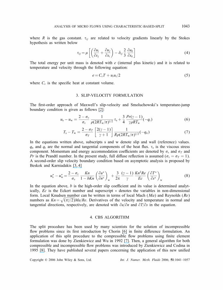
where � is the density, ui is the velocity component in xi direction, p is the pressure, T is thetemperature, gi is the ith component of the gravity acceleration, r is a heat source, k is thethermal conductivity, � is the viscosity and �ij is the Kronecker delta function. The equationsare completed by the gas state law given below
p=�RT (3)
Copyright ? 2006 John Wiley & Sons, Ltd. Int. J. Numer. Meth. Fluids 2006; 51:1041–1057
ANALYSIS OF MICRO FLOWS USING CHARACTERISTIC-BASED-SPLIT 1043
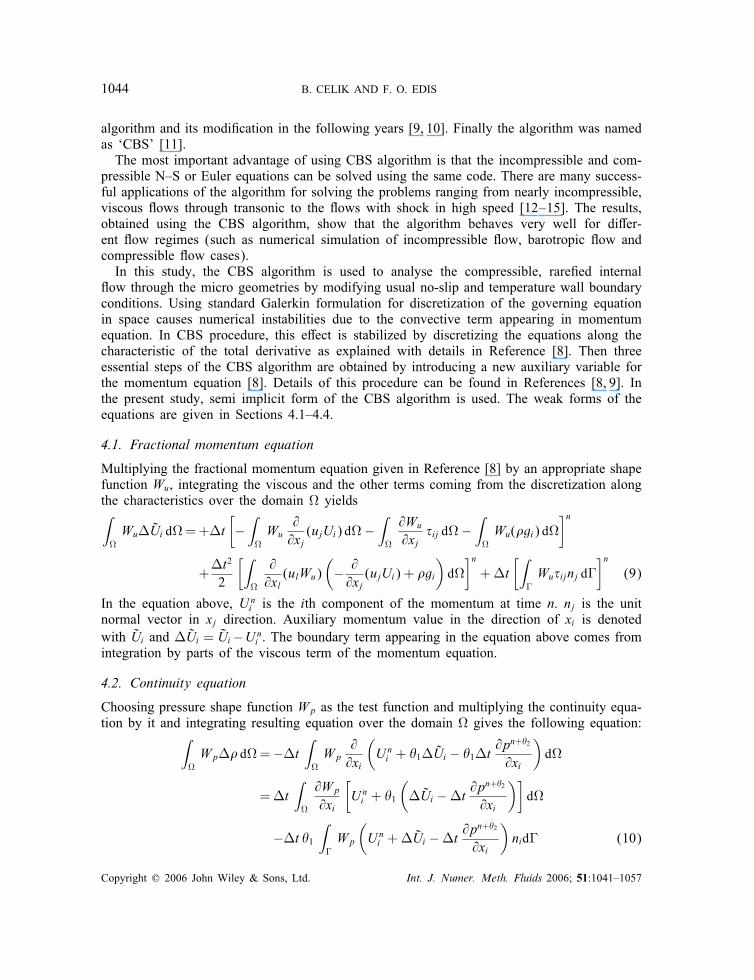
where R is the gas constant. �ij are related to velocity gradients linearly by the Stokeshypothesis as written below
�ij=�[(@ui@xj
+@uj@xi
)− �ij 23
@uk@xk
](4)
The total energy per unit mass is denoted with e (internal plus kinetic) and it is related totemperature and velocity through the following equation:
e=CvT + uiui=2 (5)
where Cv is the speci�c heat at constant volume.
3. SLIP-VELOCITY FORMULATION
The �rst-order approach of Maxwell’s slip-velocity and Smoluchowski’s temperature-jumpboundary condition is given as follows [2]:
us − uw = 2− �v�v
1�(2RTw=�)1=2
�s +34Pr(�− 1)��RTw
(−qt) (6)
Ts − Tw = 2− �T�T
[2(�− 1)�+ 1
]1
R�(2RTw=�)1=2(−qn) (7)
In the equations written above, subscripts s and w denote slip and wall (reference) values.qn and qt are the normal and tangential components of the heat �ux. �s is the viscous stresscomponent. Momentum and energy accommodation coe�cients are denoted by �v and �T andPr is the Prandtl number. In the present study, full di�use re�ection is assumed (�v = �T = 1).A second-order slip velocity boundary condition based on asymptotic analysis is proposed byBeskok and Karniadakis [3, 4]
u∗s − u∗
w =2− �v�v
Kn1− bKn
(@u∗
@n∗
)w+32�(�− 1)�
Kn2ReEc
(@T ∗
@s∗
)w
(8)
In the equation above, b is the high-order slip coe�cient and its value is determined analyt-ically, Ec is the Eckert number and superscript ∗ denotes the variables in non-dimensionalform. Local Knudsen number can be written in terms of local Mach (Ma) and Reynolds (Re)numbers as Kn=
√(��=2)Ma=Re. Derivatives of the velocity and temperature in normal and
tangential directions, respectively, are denoted with @u=@n and @T=@s in the equation.
4. CBS ALGORITHM
The split procedure has been used by many scientists for the solution of incompressible�ow problems since its �rst introduction by Chorin [6] in �nite di�erence formulation. Anapplication of this split procedure to the compressible �ow problems using �nite elementformulation was done by Zienkiewicz and Wu in 1992 [7]. Then, a general algorithm for bothcompressible and incompressible �ow problems was introduced by Zienkiewicz and Codina in1995 [8]. They have published several papers concerning the application of this new uni�ed
Copyright ? 2006 John Wiley & Sons, Ltd. Int. J. Numer. Meth. Fluids 2006; 51:1041–1057
1044 B. CELIK AND F. O. EDIS
algorithm and its modi�cation in the following years [9, 10]. Finally the algorithm was namedas ‘CBS’ [11].The most important advantage of using CBS algorithm is that the incompressible and com-
pressible N–S or Euler equations can be solved using the same code. There are many success-ful applications of the algorithm for solving the problems ranging from nearly incompressible,viscous �ows through transonic to the �ows with shock in high speed [12–15]. The results,obtained using the CBS algorithm, show that the algorithm behaves very well for di�er-ent �ow regimes (such as numerical simulation of incompressible �ow, barotropic �ow andcompressible �ow cases).In this study, the CBS algorithm is used to analyse the compressible, rare�ed internal
�ow through the micro geometries by modifying usual no-slip and temperature wall boundaryconditions. Using standard Galerkin formulation for discretization of the governing equationin space causes numerical instabilities due to the convective term appearing in momentumequation. In CBS procedure, this e�ect is stabilized by discretizing the equations along thecharacteristic of the total derivative as explained with details in Reference [8]. Then threeessential steps of the CBS algorithm are obtained by introducing a new auxiliary variable forthe momentum equation [8]. Details of this procedure can be found in References [8, 9]. Inthe present study, semi implicit form of the CBS algorithm is used. The weak forms of theequations are given in Sections 4.1–4.4.
4.1. Fractional momentum equation
Multiplying the fractional momentum equation given in Reference [8] by an appropriate shapefunction Wu, integrating the viscous and the other terms coming from the discretization alongthe characteristics over the domain � yields∫�Wu�Ui d�=+�t
[−
∫�Wu
@@xj(ujUi) d�−
∫�
@Wu
@xj�ij d�−
∫�Wu(�gi) d�
]n
+�t2
2
[∫�
@@xl(ulWu)
(− @@xj(ujUi) + �gi
)d�
]n+�t
[∫�Wu�ijnj d�
]n(9)
In the equation above, Uni is the ith component of the momentum at time n. nj is the unit
normal vector in xj direction. Auxiliary momentum value in the direction of xi is denotedwith Ui and �Ui = Ui−Un
i . The boundary term appearing in the equation above comes fromintegration by parts of the viscous term of the momentum equation.
4.2. Continuity equation
Choosing pressure shape function Wp as the test function and multiplying the continuity equa-tion by it and integrating resulting equation over the domain � gives the following equation:∫
�Wp�� d�=−�t
∫�Wp
@@xi
(Uni + �1�Ui − �1�t
@pn+�2
@xi
)d�
=�t∫�
@Wp
@xi
[Uni + �1
(�Ui −�t @p
n+�2
@xi
)]d�
−�t �1∫�Wp
(Uni +�Ui −�t
@pn+�2
@xi
)nid� (10)
Copyright ? 2006 John Wiley & Sons, Ltd. Int. J. Numer. Meth. Fluids 2006; 51:1041–1057
ANALYSIS OF MICRO FLOWS USING CHARACTERISTIC-BASED-SPLIT 1045
where pn+�2 is equal to �2pn+1 + (1 − �2)pn. In the present study, weighting function �1and �2 are selected to be 1. Pressure or density may be used as unknown in the continuityequation (10). In this study, pressure is used as unknown. Using the perfect gas law (3), thedensity variation term ��=�n+1 − �n placed on the left-hand side of the continuity equationis replaced with pressure variation term
��=�pRTg
+(pn
RTg− pn
RTn
)(11)
It is required to guess a temperature value Tg instead of unknown value of T at time n+1 touncouple the resulting continuity equation and the energy equation. It is reported in Reference[10], this approach works well if only steady state is of interest as in this study. Details ofthis approach are given in Section 4.5.
4.3. Final step of the momentum equation
Using the pressure values at time n+1 obtained from continuity equation (10) and auxiliarymomentum value, the momentum values at time n+1 are obtained from the following equationexplicitly: ∫
�Wu�Ui d�=
∫�Wu�Ui d�−�t
∫�Wu
(@pn
@xi+ �2
@�p@xi
)d�
−�t2
2
∫�
@@xj(ujWu)
@pn
@xid� (12)
where �Ui = Un+1i − Un
i . In the equation above, test function is momentum shape functionWu and �2 is taken as 1 for the explicit formulation.
4.4. Energy equation
Weak form of the energy equation with shape function of the energy (WE) as the test functionis given in the following form:∫
�WE�(�e) d�=�t
[−
∫�WE
@@xi(ui(�e+ p)) d�−
∫�
@WE
@xi
(�ijuj + k
@T@xi
)d�
]n
+�t2
2
[∫�
@@xj(ujWE)
[@@xi(−ui(�e+ p))
]d�
]n
+�t[∫
�WE
(�ijuj + k
@T@xi
)ni d�
]n(13)
where total energy per unit volume is denoted by E = (�e) and �E = En+1 − En.4.5. Solution strategy
Solution procedure for the semi-implicit form of the CBS algorithm with temperature-jumpand slip-velocity condition can be summarized as follows:
1. Solve the energy equation (13) with temperature-jump value on the wall and obtain En+1;2. Solve the fractional momentum equation (9) without any boundary condition;
Copyright ? 2006 John Wiley & Sons, Ltd. Int. J. Numer. Meth. Fluids 2006; 51:1041–1057

1046 B. CELIK AND F. O. EDIS
3. Guess a temperature Tg from En+1 using previous time step value of density and velocity�eld;
4. Solve the continuity equations (10) using Tg value and obtain pn+1. Apply slip-velocitycondition on the wall;
5. Solve the �nal step of the momentum equation (12) and obtain new momentum values;6. Obtain �n+1 from the equation of state (3) using new pressure values. Then obtainvelocity �eld from the momentum values;
7. Correct Tg using Tn+1 obtained from En+1 value by using new velocity un+1 and densityvalues �n+1;
8. Obtain temperature-jump and slip-velocity value at the wall substituting new velocityand temperature values within (7) and (8);
9. Check convergence; If not satisfactory, go to step 4;
It is reported in Reference [10], that there is no di�erence either in the numerical results orin the convergence behaviour of the CBS algorithm if more than two iterations are done.Since steady state solution is of interest, maximum iteration number is taken as 2 withinthe computation in this study except the early time steps in where the maximum iterationnumber is 3.In the present study, pseudo-quadratic velocity=linear pressure interpolation elements
(pP2P1) are used in computations [13]. The solution obtained using this kind of elements canbe considered to be obtained on two di�erent grids for the velocity and pressure solutions.Using pP2P1 type elements instead of P1P1 type elements makes the sti�ness matrix in thecontinuity equation four times smaller for 2-D problems. Since the continuity equation formsthe implicit part of the CBS algorithm, any reduction in the size of this equation reducethe storage requirements and number of calculations. It is reported that computational timesare reduced up to 59% when pP2P1 type FEM elements are used within the CBS algorithminstead of P1P1 type elements while this ratio is 56% for alternative Petrov–Galerkin FEMmethod [13].For the pressure driven compressible internal �ows, locally very high pressure gradients and
high velocities may be observed at the initial steps of the analysis if the initial solution is not avery good approximation of the steady state solution. When micro�uidic boundary conditionsare used, these initial disturbances produce unrealistic slip and temperature-jump values andcause the inner iterations of the CBS algorithm to diverge. Therefore, it is important to useno-slip conditions for the initial steps of the analysis.
5. RESULTS AND DISCUSSION
5.1. Straight micro channel
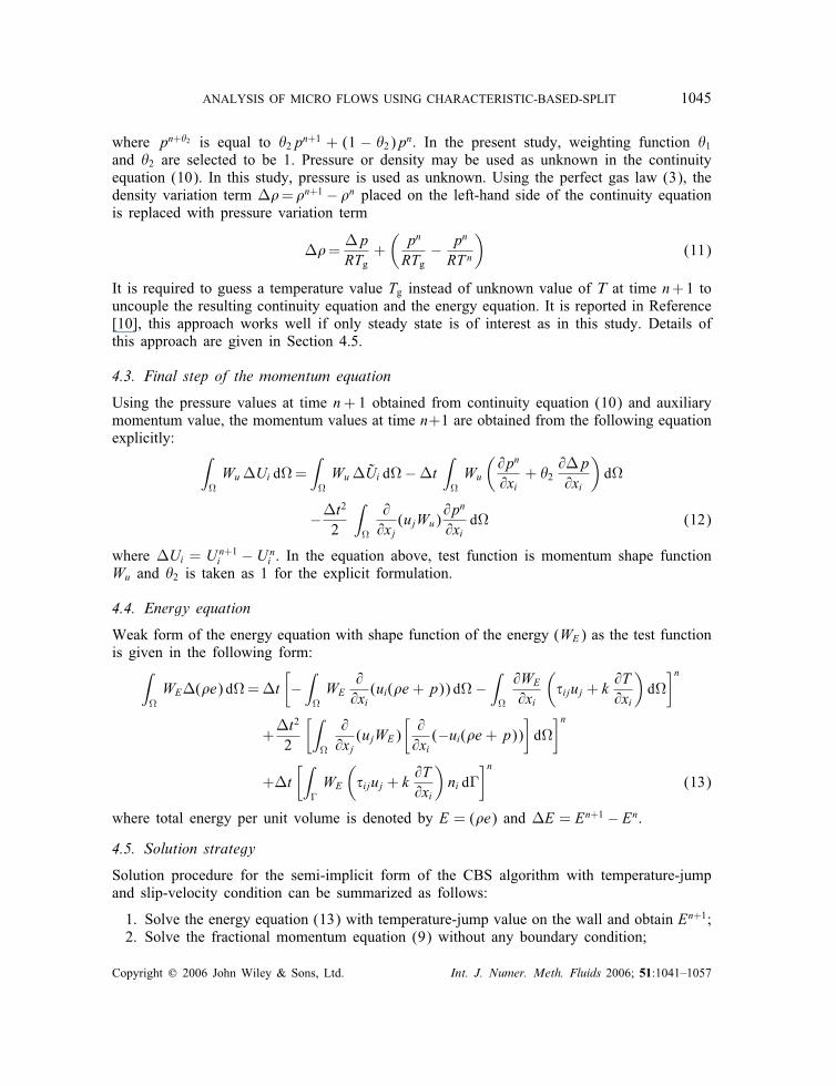
To verify the second-order slip-velocity boundary condition within the CBS algorithm, straightmicro channel is selected as a test case. Pressure ratio of the channel inlet to the outlet (�)is equal to 2.28 and outlet Knudsen number (Knout) is equal to 0.2 . The �ow is assumed tobe isothermal and reference temperature is taken as 273 K. Fifty-three and 21 grid points aretaken in horizontal and vertical direction for the velocity mesh (see Figure 1). Total numberof triangular elements used for the velocity calculation is 2080. The ratio of the channel lengthto the height (L=h) is equal to 20 and working �uid is Nitrogen with speci�c heat ratio of 1.4.
Copyright ? 2006 John Wiley & Sons, Ltd. Int. J. Numer. Meth. Fluids 2006; 51:1041–1057
ANALYSIS OF MICRO FLOWS USING CHARACTERISTIC-BASED-SPLIT 1047
Figure 1. Velocity mesh of straight micro channel.
Figure 2. Velocity distribution along the straight micro channel with no-slip (upper) andslip-velocity (lower) boundary conditions.
The velocity vectors obtained using no-slip (NS) and with slip-velocity (WS) boundaryconditions are plotted for comparison in Figure 2. The increase in the slip-velocity along thechannel walls can be seen in the �gure.The pressure values are prescribed at the channel inlet and the outlet according to the
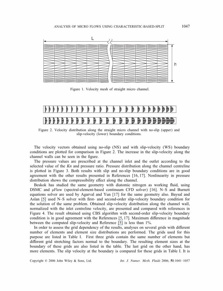
selected value of the Kn and pressure ratio. Pressure distribution along the channel centrelineis plotted in Figure 3. Both results with slip and no-slip boundary conditions are in goodagreement with the other results presented in References [16, 17]. Nonlinearity in pressuredistribution shows the compressibility e�ect along the channel.Beskok has studied the same geometry with diatomic nitrogen as working �uid, using
DSMC and �Flow (spectral-element-based continuum CFD solver) [16]. N–S and Burnettequations solver are used by Agarval and Yun [17] for the same geometry also. Baysal andAslan [5] used N–S solver with �rst- and second-order slip-velocity boundary condition forthe solution of the same problem. Obtained slip-velocity distribution along the channel wall,normalized with the inlet centreline velocity, are presented and compared with references inFigure 4. The result obtained using CBS algorithm with second-order slip-velocity boundarycondition is in good agreement with the References [5, 17]. Maximum di�erence in magnitudebetween the computed slip-velocity and Reference [5] is less than 1%.In order to assess the grid dependency of the results, analyses on several grids with di�erent
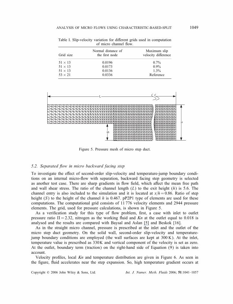
number of elements and element size distributions are performed. The grids used for thispurpose are listed in Table I. First three grids contain the same number of elements butdi�erent grid stretching factors normal to the boundary. The resulting element sizes at theboundary of these grids are also listed in the table. The last grid on the other hand, hasmore elements. The slip velocity at the boundary is compared for these grids in Table I. It is
Copyright ? 2006 John Wiley & Sons, Ltd. Int. J. Numer. Meth. Fluids 2006; 51:1041–1057
1048 B. CELIK AND F. O. EDIS
x/L
P in /
P out
0 0.2 0.4 0.6 0.8 11
1.1
1.2
1.3
1.4
1.5
1.6
1.7
1.8
1.9
2
2.1
2.2
Baysal & Aslan WS [5]Beskok [16]Baysal & Aslan NS [5]Analytical [3]Computed WSComputed NS
Figure 3. Pressure distribution along the straight micro channel centreline, Knout = 0:2.
x/L
u WS
/uce
nt_i
n
0 0.2 0.4 0.6 0.8 10
0.1
0.2
0.3
0.4
0.5
0.6
0.7
0.8
0.9
1
Agarwal&Yun [17]Analytical [3]Beskok [16]Baysal&Aslan WS (1st order ) [5]Baysal&Aslan WS (2nd order) [5]Computed
Figure 4. Slip velocity variation along straight micro channel wall, Knout = 0:2, � = 2:28.
shown that the maximum di�erence in magnitude between the slip-velocity values obtainedusing di�erent meshes is less than 2%.The obtained velocity distributions and comparisons show that, the implementation of
second-order slip-velocity boundary condition to the CBS algorithm yields accurate resultsfor this test case.
Copyright ? 2006 John Wiley & Sons, Ltd. Int. J. Numer. Meth. Fluids 2006; 51:1041–1057
ANALYSIS OF MICRO FLOWS USING CHARACTERISTIC-BASED-SPLIT 1049
Table I. Slip-velocity variation for di�erent grids used in computationof micro channel �ow.
Normal distance of Maximum slipGrid size the �rst node velocity di�erence
51× 13 0.0196 0.7%51× 13 0.0173 0.9%51× 13 0.0136 1.3%53× 21 0.0336 Reference
L
h
S
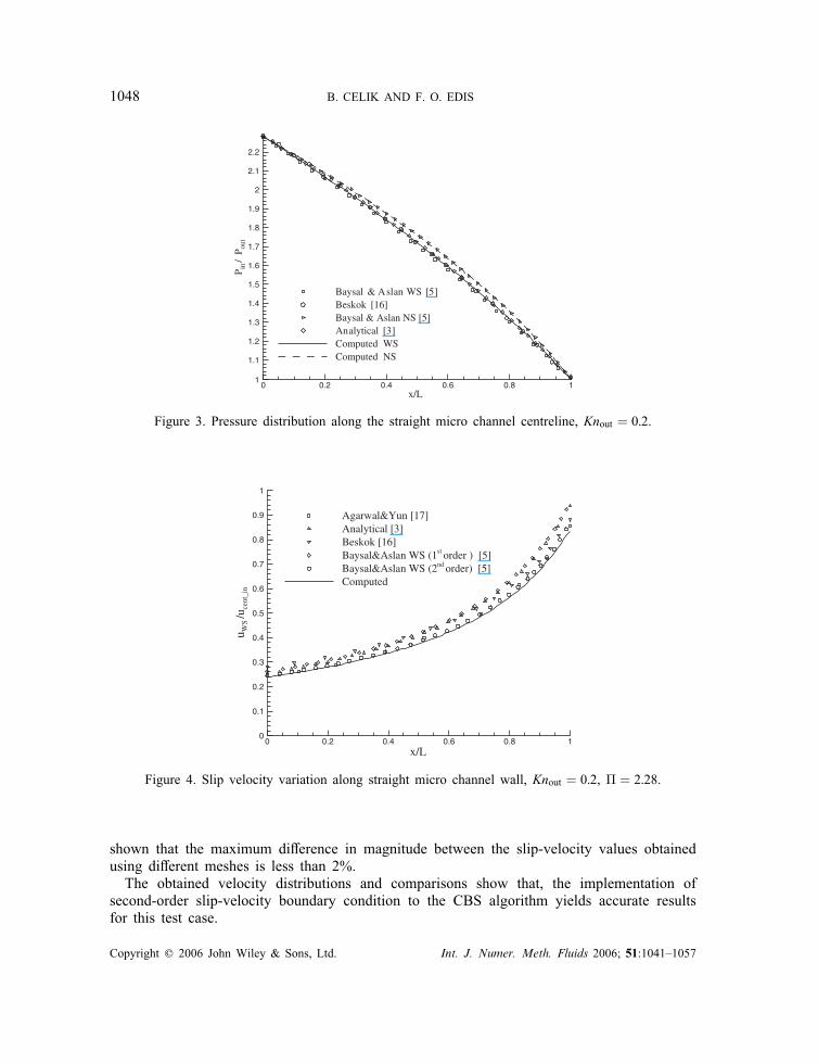
Figure 5. Pressure mesh of micro step duct.
5.2. Separated �ow in micro backward facing step
To investigate the e�ect of second-order slip-velocity and temperature-jump boundary condi-tions on an internal micro-�ow with separation, backward facing step geometry is selectedas another test case. There are sharp gradients in �ow �eld, which a�ect the mean free pathand wall shear stress. The ratio of the channel length (L) to the exit height (h) is 5.6. Thechannel entry is also included to the simulation and it is located at x=h=0:86. Ratio of stepheight (S) to the height of the channel h is 0.467. pP2P1 type of elements are used for thesecomputations. The computational grid consists of 11 776 velocity elements and 2944 pressureelements. The grid, used for pressure calculations, is shown in Figure 5.As a veri�cation study for this type of �ow problem, �rst, a case with inlet to outlet
pressure ratio �=2:32, nitrogen as the working �uid and Kn at the outlet equal to 0.018 isanalysed and the results are compared with Baysal and Aslan [5] and Beskok [16].As in the straight micro channel, pressure is prescribed at the inlet and the outlet of the
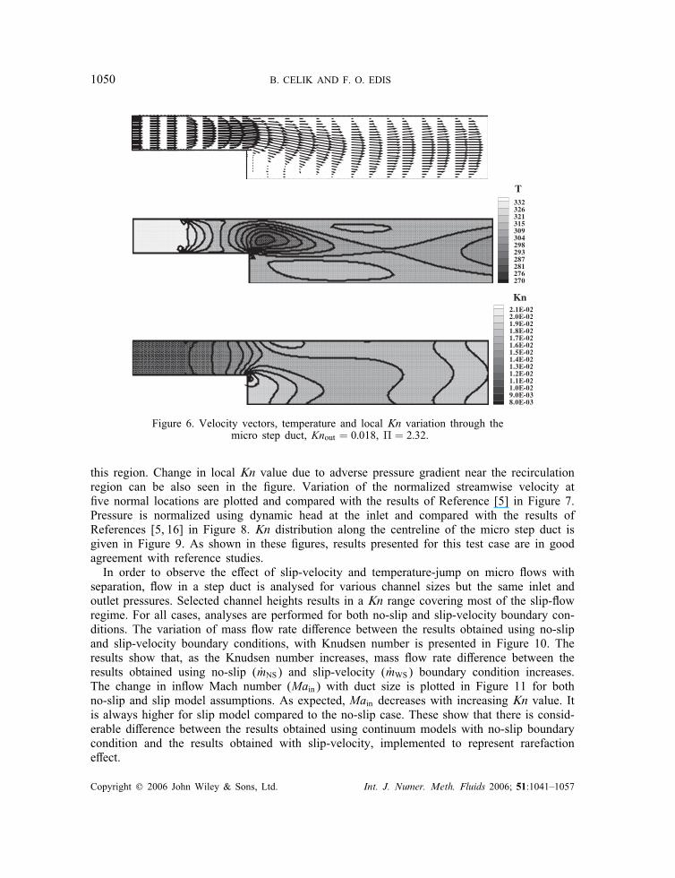
micro step duct geometry. On the solid wall, second-order slip-velocity and temperature-jump boundary conditions are employed (the wall surfaces are kept at 300 K). At the inlet,temperature value is prescribed as 330K and vertical component of the velocity is set as zero.At the outlet, boundary term (traction) on the right-hand side of Equation (9) is taken intoaccount.Velocity pro�les, local Kn and temperature distribution are given in Figure 6. As seen in
the �gure, �uid accelerates near the step expansion. So, high temperature gradient occurs at
Copyright ? 2006 John Wiley & Sons, Ltd. Int. J. Numer. Meth. Fluids 2006; 51:1041–1057
1050 B. CELIK AND F. O. EDIS
2.1E-022.0E-021.9E-021.8E-021.7E-021.6E-021.5E-021.4E-021.3E-021.2E-021.1E-021.0E-029.0E-038.0E-03
Kn
332326321315309304298293287281276270
T
Figure 6. Velocity vectors, temperature and local Kn variation through themicro step duct, Knout = 0:018, � = 2:32.
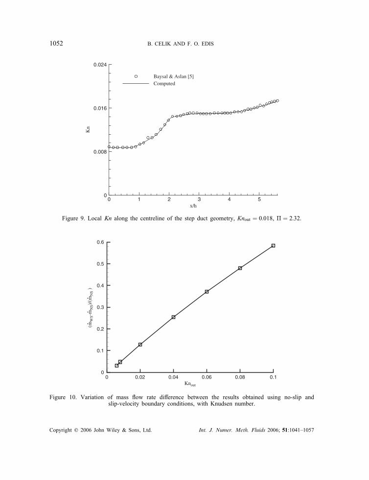
this region. Change in local Kn value due to adverse pressure gradient near the recirculationregion can be also seen in the �gure. Variation of the normalized streamwise velocity at�ve normal locations are plotted and compared with the results of Reference [5] in Figure 7.Pressure is normalized using dynamic head at the inlet and compared with the results ofReferences [5, 16] in Figure 8. Kn distribution along the centreline of the micro step duct isgiven in Figure 9. As shown in these �gures, results presented for this test case are in goodagreement with reference studies.In order to observe the e�ect of slip-velocity and temperature-jump on micro �ows with
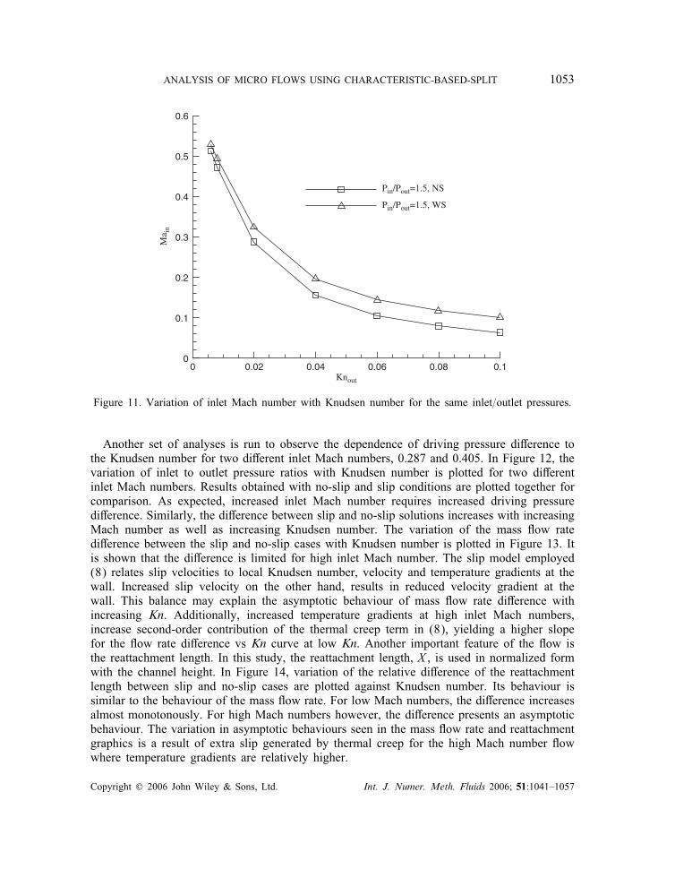
separation, �ow in a step duct is analysed for various channel sizes but the same inlet andoutlet pressures. Selected channel heights results in a Kn range covering most of the slip-�owregime. For all cases, analyses are performed for both no-slip and slip-velocity boundary con-ditions. The variation of mass �ow rate di�erence between the results obtained using no-slipand slip-velocity boundary conditions, with Knudsen number is presented in Figure 10. Theresults show that, as the Knudsen number increases, mass �ow rate di�erence between theresults obtained using no-slip (mNS) and slip-velocity (mWS) boundary condition increases.The change in in�ow Mach number (Main) with duct size is plotted in Figure 11 for bothno-slip and slip model assumptions. As expected, Main decreases with increasing Kn value. Itis always higher for slip model compared to the no-slip case. These show that there is consid-erable di�erence between the results obtained using continuum models with no-slip boundarycondition and the results obtained with slip-velocity, implemented to represent rarefactione�ect.
Copyright ? 2006 John Wiley & Sons, Ltd. Int. J. Numer. Meth. Fluids 2006; 51:1041–1057

ANALYSIS OF MICRO FLOWS USING CHARACTERISTIC-BASED-SPLIT 1051
x/h
u/c
1 2 3 4 5-0.2
0
0.2
0.4
0.6
0.8
1
1.2 y/h=0.7550 Baysal&Aslan[5]y/h=0.9901 Baysal&Aslan[5]y/h=0.4978 Baysal&Aslan[5]y/h=0.2476 Baysal&Aslan[5]y/h=0.01456 Baysal&Aslan[5]y/h=0.01456y/h=0.2476y/h=0.4978y/h=0.7550y/h=0.9901
Figure 7. Comparison of normalized streamwise velocity with Baysal andAslan [5], Knout = 0:018, � = 2:32.
x/h
P/q i
n
0 1 2 3 4 52
2.5
3
3.5
4
4.5
5
5.5
6
6.5
7
Beskok [16]
Baysal & Aslan [5]
Computed
Figure 8. Pressure variation along the channel, Knout = 0:018, � = 2:32.
Copyright ? 2006 John Wiley & Sons, Ltd. Int. J. Numer. Meth. Fluids 2006; 51:1041–1057
1052 B. CELIK AND F. O. EDIS
x/h0 1 2 3 4 5
0
0.008
0.016
0.024
Baysal & Aslan [5]Computed
Kn
Figure 9. Local Kn along the centreline of the step duct geometry, Knout = 0:018, � = 2:32.
Knout
(mW
S-m
NS)
/(m
NS
)
.
.
.
0 0.02 0.04 0.06 0.08 0.10
0.1
0.2
0.3
0.4
0.5
0.6
Figure 10. Variation of mass �ow rate di�erence between the results obtained using no-slip andslip-velocity boundary conditions, with Knudsen number.
Copyright ? 2006 John Wiley & Sons, Ltd. Int. J. Numer. Meth. Fluids 2006; 51:1041–1057
ANALYSIS OF MICRO FLOWS USING CHARACTERISTIC-BASED-SPLIT 1053
Knout
Ma i
n
0 0.02 0.04 0.06 0.08 0.10
0.1
0.2
0.3
0.4
0.5
0.6
Pin/Pout=1.5, NS
Pin/Pout=1.5, WS
Figure 11. Variation of inlet Mach number with Knudsen number for the same inlet=outlet pressures.
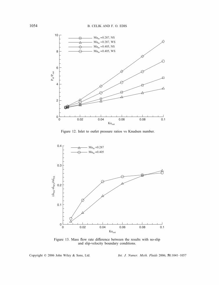
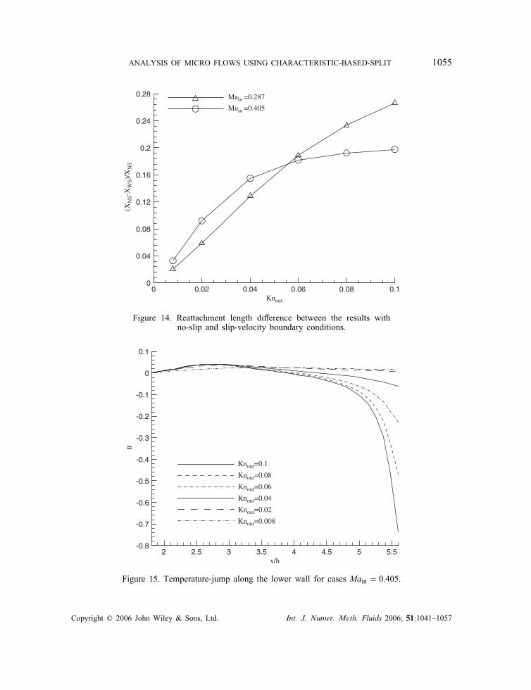
Another set of analyses is run to observe the dependence of driving pressure di�erence tothe Knudsen number for two di�erent inlet Mach numbers, 0.287 and 0.405. In Figure 12, thevariation of inlet to outlet pressure ratios with Knudsen number is plotted for two di�erentinlet Mach numbers. Results obtained with no-slip and slip conditions are plotted together forcomparison. As expected, increased inlet Mach number requires increased driving pressuredi�erence. Similarly, the di�erence between slip and no-slip solutions increases with increasingMach number as well as increasing Knudsen number. The variation of the mass �ow ratedi�erence between the slip and no-slip cases with Knudsen number is plotted in Figure 13. Itis shown that the di�erence is limited for high inlet Mach number. The slip model employed(8) relates slip velocities to local Knudsen number, velocity and temperature gradients at thewall. Increased slip velocity on the other hand, results in reduced velocity gradient at thewall. This balance may explain the asymptotic behaviour of mass �ow rate di�erence withincreasing Kn. Additionally, increased temperature gradients at high inlet Mach numbers,increase second-order contribution of the thermal creep term in (8), yielding a higher slopefor the �ow rate di�erence vs Kn curve at low Kn. Another important feature of the �ow isthe reattachment length. In this study, the reattachment length, X , is used in normalized formwith the channel height. In Figure 14, variation of the relative di�erence of the reattachmentlength between slip and no-slip cases are plotted against Knudsen number. Its behaviour issimilar to the behaviour of the mass �ow rate. For low Mach numbers, the di�erence increasesalmost monotonously. For high Mach numbers however, the di�erence presents an asymptoticbehaviour. The variation in asymptotic behaviours seen in the mass �ow rate and reattachmentgraphics is a result of extra slip generated by thermal creep for the high Mach number �owwhere temperature gradients are relatively higher.
Copyright ? 2006 John Wiley & Sons, Ltd. Int. J. Numer. Meth. Fluids 2006; 51:1041–1057
1054 B. CELIK AND F. O. EDIS
Knout
P in/
P out
0 0.02 0.04 0.06 0.08 0.10
2
4
6
8
10Main =0.287, NS
Main =0.287, WS
Main =0.405, NS
Main =0.405, WS
Figure 12. Inlet to outlet pressure ratios vs Knudsen number.
Knout
0 0.02 0.04 0.06 0.08 0.10
0.1
0.2
0.3
0.4 Main =0.287
Main =0.405
(mN
S-m
WS)
/mN
S
.
.
.
Figure 13. Mass �ow rate di�erence between the results with no-slipand slip-velocity boundary conditions.
Copyright ? 2006 John Wiley & Sons, Ltd. Int. J. Numer. Meth. Fluids 2006; 51:1041–1057
ANALYSIS OF MICRO FLOWS USING CHARACTERISTIC-BASED-SPLIT 1055
Knout
(XN
S-X
WS)
/XN
S
0 0.02 0.04 0.06 0.08 0.10
0.04
0.08
0.12
0.16
0.2
0.24
0.28 Main =0.287
Main =0.405
Figure 14. Reattachment length di�erence between the results withno-slip and slip-velocity boundary conditions.
x/h
θ
2 2.5 3 3.5 4 4.5 5 5.5-0.8
-0.7
-0.6
-0.5
-0.4
-0.3
-0.2
-0.1
0
0.1
Knout=0.1
Knout=0.08
Knout=0.06
Knout=0.04
Knout=0.02
Knout=0.008
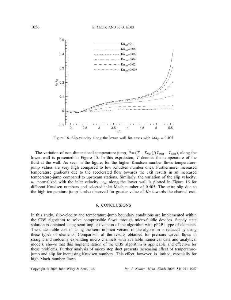
Figure 15. Temperature-jump along the lower wall for cases Main = 0:405.
Copyright ? 2006 John Wiley & Sons, Ltd. Int. J. Numer. Meth. Fluids 2006; 51:1041–1057
1056 B. CELIK AND F. O. EDIS
u s/u
in
2 3 4 5
0
x/h2.5 3.5 4.5 5.5
-0.1
0.5
0.4
0.3
0.2
0.1
Knout=0.1
Knout=0.08
Knout=0.06
Knout=0.04
Knout=0.02
Knout=0.008
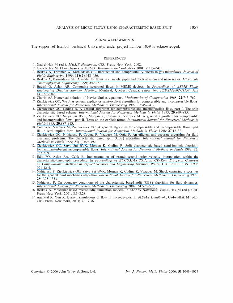
Figure 16. Slip-velocity along the lower wall for cases with Main = 0:405.
The variation of non-dimensional temperature-jump, �=(T −Twall)=(Tinlet−Twall), along thelower wall is presented in Figure 15. In this expression, T denotes the temperature of the�uid at the wall. As seen in the �gure, for the higher Knudsen number �ows temperature-jump values are very high compared to low Knudsen number ones. Furthermore, increasedtemperature gradients due to the accelerated �ow towards the exit results in an increasedtemperature-jump compared to upstream stations. Similarly, the variation of the slip velocity,us, normalized with the inlet velocity, uin, along the lower wall is plotted in Figure 16 fordi�erent Knudsen numbers and selected inlet Mach number of 0.405. The extra slip due tothe high temperature jump is also observed for greater value of Kn towards the channel exit.
6. CONCLUSIONS
In this study, slip-velocity and temperature-jump boundary conditions are implemented withinthe CBS algorithm to solve compressible �ows through micro-�uidic devices. Steady statesolution is obtained using semi-implicit version of the algorithm with pP2P1 type of elements.The undesirable cost of using the semi-implicit version of the algorithm is reduced by usingthese types of elements. Comparison of the results obtained for pressure driven �ows instraight and suddenly expanding micro channels with available numerical data and analyticalmodels, shows that this implementation of the CBS algorithm is applicable and e�ective forthese problems. Further analysis of micro step duct presents increasing e�ect of temperature-jump and slip for increasing Knudsen numbers. This e�ect, however, is limited, especially forhigh Mach number �ows.
Copyright ? 2006 John Wiley & Sons, Ltd. Int. J. Numer. Meth. Fluids 2006; 51:1041–1057
ANALYSIS OF MICRO FLOWS USING CHARACTERISTIC-BASED-SPLIT 1057
ACKNOWLEDGEMENTS
The support of Istanbul Technical University, under project number 1839 is acknowledged.
REFERENCES
1. Gad-el-Hak M (ed.). MEMS Handbook. CRC Press: New York, 2002.2. Gad-el-Hak M. Flow physics in MEMS. Mecanique and Industries 2001; 2:313–341.3. Beskok A, Trimmer W, Karniadakis GE. Rarefaction and compressibility e�ects in gas micro�ows. Journal ofFluids Engineering 1996; 118(2):448–456.
4. Beskok A, Karniadakis GE. A model for �ows in channels, pipes and ducts at micro and nano scales. MicroscaleThermophysical Engineering 1999; 3:43–77.
5. Baysal O, Aslan AR. Computing separated �ows in MEMS devices. In Proceedings of ASME FluidsEngineering Division Summer Meeting, Montreal, Quebec, Canada. Paper No. FEDSM2002-31157, July14–18, 2002.
6. Chorin AJ. Numerical solution of Navier–Stokes equations. Mathematics of Computation 1968; 22:745–762.7. Zienkiewicz OC, Wu J. A general explicit or semi-explicit algorithm for compressible and incompressible �ows.International Journal for Numerical Methods in Engineering 1992; 35:457–479.
8. Zienkiewicz OC, Codina R. A general algorithm for compressible and incompressible �ow, part I. The splitcharacteristic based scheme. International Journal for Numerical Methods in Fluids 1995; 20:869–885.
9. Zienkiewicz OC, Satya Sai BVK, Morgan K, Codina R, Vazquez M. A general algorithm for compressibleand incompressible �ow—part II. Tests on the explicit forms. International Journal for Numerical Methods inFluids 1995; 20:887–913.
10. Codina R, Vazquez M, Zienkiewicz OC. A general algorithm for compressible and incompressible �ows, partIII—a semi-implicit form. International Journal for Numerical Methods in Fluids 1998; 27:12–32.
11. Zienkiewicz OC, Nithiarasu P, Codina R, Vazquez M, Ortiz P. An e�cient and accurate algorithm for �uidmechanic problems. The characteristic based split (CBS) algorithm. International Journal for NumericalMethods in Fluids 1999; 31(1):359–392.
12. Zienkiewicz OC, Satya Sai BVK, Morgan K, Codina R. Split characteristic based semi-implicit algorithmfor laminar=turbulent incompressible �ows. International Journal for Numerical Methods in Fluids 1998; 23:787–809.
13. Edis FO, Aslan RA, Celik B. Implementation of pseudo-second order velocity interpolation within thecharacteristic-based-split procedure. In Proceedings of ECCOMAS 2001, on CD-Rom European Congresson Computational Methods in Applied Sciences and Engineering, Swansea, Wales, U.K., 2001. ISBN 0 905091 12 4.
14. Nithiarasu P, Zienkiewicz OC, Satya Sai BVK, Morgan K, Codina R, Vazquez M. Shock capturing viscositiesfor the general �uid mechanics algorithm. International Journal for Numerical Methods in Engineering 1998;28:1325–1353.
15. Nithiarasu P. On boundary conditions of the characteristic based split (CBS) algorithm for �uid dynamics.International Journal for Numerical Methods in Engineering 2002; 54:523–536.
16. Beskok A. Molecular based micro�uidic simulation models. In MEMS Handbook, Gad-el-Hak M (ed.). CRCPress: New York, 2001; 8.1–8.28.
17. Agarwal R, Yun K. Burnett simulations of �ow in microdevices. In MEMS Handbook, Gad-el-Hak M (ed.).CRC Press: New York, 2001; 7.1–7.36.
Copyright ? 2006 John Wiley & Sons, Ltd. Int. J. Numer. Meth. Fluids 2006; 51:1041–1057