Varying frontal thrust spacing in mono-vergent wedges: An insight from analogue models
16
Varying frontal thrust spacing in mono-vergent wedges: An insight from analogue models Puspendu Saha 1 , Santanu Bose 1,∗ and Nibir Mandal 2 1 Experimental Tectonics Laboratory, Department of Geology, University of Calcutta, Kolkata 700 019, India. 2 Department of Geological Sciences, Jadavpur University, Kolkata 700 032, India. ∗ Corresponding author. e-mail: [email protected] Sandbox experiments are used to study frontal thrust fault spacing, which is a function of physical properties within the thrust wedge. We consider three styles of thrust progression in mono-vergent wedges: Style I, II and III. In Style I, frontal thrusts progress forelandward, maintaining a constant spacing, whereas Style II and Style III progression show increasing and decreasing spacing, respectively. The three styles are shown as a function of the following factors: basal friction (μ b ), initial surface slope (α) and basal slopes (β ), and surface erosion. For high μ b (∼0.46), thrust progression occurs in Style II when α< 2 ◦ and β< 0.5 ◦ , and in Style III when α and β are high (α> 2 ◦ and β> 0.5 ◦ ). Style II transforms to Style I when the wedge undergoes syn-thrusting surface erosion. In contrast, low-basal friction (μ b =0.36) gives rise to either Style I or III, depending on the magnitudes of α and β . Conditions with α = β = 0 developed Style I, whereas Style III in conditions with any non-zero values of α and β . In this case, surface erosion caused the process of thrust progression unsteady, and prompted out- of-sequence thrusting in the wedge. This study finally presents an analysis of the three styles, taking into account the following two parameters: (1) instantaneous increase of hinterland thickness (ΔH e /H e ) and (2) forelandward gradient of wedge thickness (δH/δx). Experimental data suggest that thrust sequences develop in Style II for low δH/δx and large δH e /H e values and, in Style III as either δH/δx increases or ΔH e /H e drops. 1. Introduction Crustal lithosphere in the active convergent plate boundaries undergoes sequential thrusting, form- ing tectonic wedges in the mountain belts and subduction zones. A line of tectonic studies is con- cerned with the mechanical modelling of wedges, assuming that the upper crust deforms like a Coulomb material (Chapple 1978; Davis et al. 1983; Dahlen et al. 1984). These models explain the development of a Coulomb wedge as if a sheet of granular material piles up in front of a moving bull- dozer, comparable to the overriding lithospheric plate in the convergent setting. The phenomenon has been theorized to explain the wedge dynam- ics as a function of geometrical and mechanical parameters. The theory postulates that the wedge material deforms internally until it attains a criti- cal taper. A critically tapered wedge would tend to slide stably at its base without any further internal deformation. Furthermore, the wedge at its critical taper turns to be on the verge of failure, forming thrusts. A critically tapered wedge develops succes- sively new frontal thrusts in the course of its fore- landward progression (Mulugeta 1988; Liu et al. 1992; Mandal et al. 1997; Schott and Koyi 2001; Keywords. Fold-and-thrust belts; sandbox experiments; basal friction; surface slope; surface erosion. J. Earth Syst. Sci. 122, No. 3, June 2013, pp. 699–714 c Indian Academy of Sciences 699
Transcript of Varying frontal thrust spacing in mono-vergent wedges: An insight from analogue models
Varying frontal thrust spacing in mono-vergent wedges:An insight from analogue models
Puspendu Saha1, Santanu Bose
1,∗ and Nibir Mandal2
1Experimental Tectonics Laboratory, Department of Geology, University of Calcutta, Kolkata 700 019, India.2Department of Geological Sciences, Jadavpur University, Kolkata 700 032, India.
∗Corresponding author. e-mail: [email protected]
Sandbox experiments are used to study frontal thrust fault spacing, which is a function of physicalproperties within the thrust wedge. We consider three styles of thrust progression in mono-vergentwedges: Style I, II and III. In Style I, frontal thrusts progress forelandward, maintaining a constantspacing, whereas Style II and Style III progression show increasing and decreasing spacing, respectively.The three styles are shown as a function of the following factors: basal friction (μb), initial surfaceslope (α) and basal slopes (β), and surface erosion. For high μb (∼0.46), thrust progression occurs inStyle II when α < 2◦ and β < 0.5◦, and in Style III when α and β are high (α > 2◦ and β > 0.5◦).Style II transforms to Style I when the wedge undergoes syn-thrusting surface erosion. In contrast,low-basal friction (μb = 0.36) gives rise to either Style I or III, depending on the magnitudes of α and β.Conditions with α = β = 0 developed Style I, whereas Style III in conditions with any non-zero values of αand β. In this case, surface erosion caused the process of thrust progression unsteady, and prompted out-of-sequence thrusting in the wedge. This study finally presents an analysis of the three styles, taking intoaccount the following two parameters: (1) instantaneous increase of hinterland thickness (ΔHe/He) and(2) forelandward gradient of wedge thickness (δH/δx). Experimental data suggest that thrust sequencesdevelop in Style II for low δH/δx and large δHe/He values and, in Style III as either δH/δx increasesor ΔHe/He drops.
1. Introduction
Crustal lithosphere in the active convergent plateboundaries undergoes sequential thrusting, form-ing tectonic wedges in the mountain belts andsubduction zones. A line of tectonic studies is con-cerned with the mechanical modelling of wedges,assuming that the upper crust deforms like aCoulomb material (Chapple 1978; Davis et al.1983; Dahlen et al. 1984). These models explain thedevelopment of a Coulomb wedge as if a sheet ofgranular material piles up in front of a moving bull-dozer, comparable to the overriding lithospheric
plate in the convergent setting. The phenomenonhas been theorized to explain the wedge dynam-ics as a function of geometrical and mechanicalparameters. The theory postulates that the wedgematerial deforms internally until it attains a criti-cal taper. A critically tapered wedge would tend toslide stably at its base without any further internaldeformation. Furthermore, the wedge at its criticaltaper turns to be on the verge of failure, formingthrusts. A critically tapered wedge develops succes-sively new frontal thrusts in the course of its fore-landward progression (Mulugeta 1988; Liu et al.1992; Mandal et al. 1997; Schott and Koyi 2001;
Keywords. Fold-and-thrust belts; sandbox experiments; basal friction; surface slope; surface erosion.
J. Earth Syst. Sci. 122, No. 3, June 2013, pp. 699–714c© Indian Academy of Sciences 699
700 Puspendu Saha et al.
Agarwal and Agarwal 2002; Bose et al. 2009). Thisstudy deals with varying thrust spacing observedin natural fold-thrust-belt, which involves primar-ily the upper brittle part of the lithosphere (Butler1992; Jadoon et al. 1992; Goff et al. 1996; Panianand Wiltschko 2004).
Despite significant advancement in thrust tec-tonics, understanding of thrust locations and theirspatio-temporal variations is still incomplete. Sev-eral earlier studies took into account the effects ofinherent topographic, mechanical heterogeneitiesor frictional coefficient in basal detachment todemonstrate localization of a thrust ramp in con-vergent tectonic zones (Wiltschko and Eastman1982; Davis and Engelder 1985; Knipe 1985;Bombalakis 1986; Platt 1986; Cello and Nurr1988; Geiser 1988). In a recent study Panian andWiltschko (2007) have, however, argued that ramplocalization can occur without any such inherentimperfection in the system. Using finite elementmodels they have shown that plastic shear bandspreferentially localize frontalward in the form ofthrust ramps, maintaining a definite distance fromthe earlier ramp. According to their models, rampspacing in a tapered crustal section decreases fore-landward, as can be enumerated from a linearrelation between thrust spacing and bed thickness(Liu et al. 1992; Mandal et al. 1997). On the otherhand, some sandbox experiments exhibit increas-ing ramp spacing in beds with a uniform initialthickness, which is attributed to increasing hin-terland elevation of thrust wedges (Mulugeta andKoyi 1987; Bose et al. 2009). Frontal thrust pro-gression can occur with a uniform spacing onlywhen a stable elevation of the wedge is maintained(Bose et al. 2009). There are several factors, such assurface erosion, surface slope and basal slope, thatcontrol the growth of tectonic wedges, and in turngovern the process of frontal thrust progression.Recent field and experimental observations sug-gest that focused surface denudation can result inlocalization of thrusts (Avouac and Burov 1996;Konstantinovskaia and Malavieille 2005; Hoth2006; Hoth et al. 2006).
All the studies discussed above dealt with thrustwedges developing on rigid bases with frictionalcontact. However, many fold-and-thrust belts showa ductile horizon at their base. Smit et al. (2003)have shown that the relative strength of brittlecover and ductile base (brittle–ductile coupling)controls the mode of frontal thrust progression.Weak brittle–ductile coupling, depending on basalslope (β) and shortening velocity (V ), promotesbackward thrusting sequences, which are replacedby frontward thrust sequences, as the brittle–ductile coupling becomes strong with lowering βand increasing V . The coupling strength also deter-mines the spacing of frontal thrusts. In case of
strong coupling, frontal thrusts form at closed spac-ing that remains uniform during frontward thrustprogression. The spacing shows an inverse relationwith the brittle–ductile coupling.
Several researchers have shown that the devel-opment of thrust sequences depends also on thegeometry of the overriding plate and the natureof its mechanical contact with the accretionarywedge. For example, frontal and back thrustscan form spatially in close association, form-ing a complex architecture when the indentingplate pushes into the Coulomb crustal material(Malavieille 1984; Koons 1990; Storti et al. 2000;Persson and Sokoutis 2002). Other researchers havereported similar thrust architecture, taking intoaccount the effect of a singularity of basal velocity(Willett 1999; Storti et al. 2000). The style ofthrust sequences becomes more complex when theprocess occurs simultaneously with synorogenicsurface erosion, as observed in sandbox experi-ments (Konstantinovskaia and Malavieille 2005;Bose and Mandal 2010).
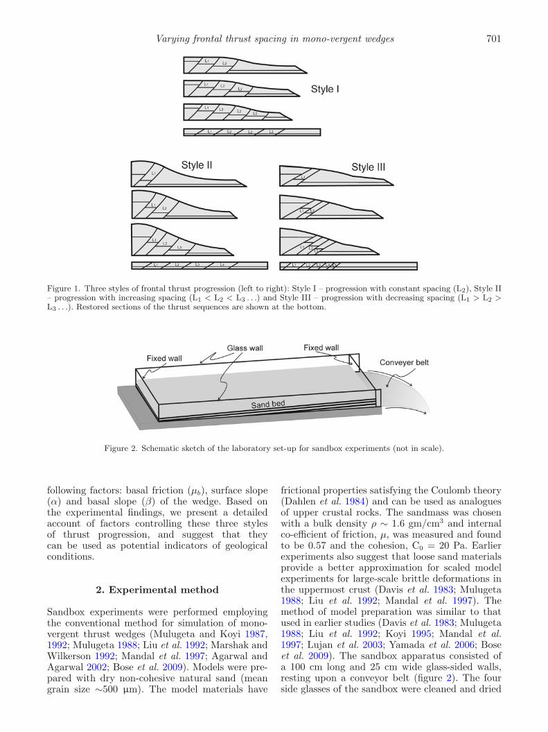
It follows from the above discussions that theprogression of frontal thrusts is a product of dif-ferent interacting surface and tectonic processes.Many mountain belts, for example, the Himalayanfront contain relatively simple thrust sequencescharacterized by systematically arranged forelandvergent thrusts (Srivastava and Mitra 1994;DeCelles et al. 1998; Avouac 2007). This type ofthrust architecture has been widely investigatedusing both analogue and numerical models, con-sidering mono-vergent Coulomb wedges formedagainst vertical buttresses (Mulugeta and Koyi1987, 1992; Mulugeta 1988; Liu et al. 1992;Marshak and Wilkerson 1992; Mandal et al. 1997;Gutscher et al. 1998a, b; Panian and Wiltschko2007; Bose et al. 2009). We performed sandboxexperiments to study the progression behaviour offrontal thrusts in such mono-vergent wedges. Basedon the initial spacing of successive frontal thrustsin sandbox experiments, we define three principalstyles of thrust progression (figure 1).
• Style I : Frontal thrusts progress in the forelanddirection, maintaining a constant spacing. Thistype of thrust sequence is observed in many fold-thrust-belts, e.g., Sulaiman FTBs (Jadoon et al.1992).
• Style II : Progression of frontal thrusts occurswith continuously increasing lateral spacing, asobserved in the Pyrenees (Goff et al. 1996;Panian and Wiltschko 2004).
• Style III : Thrust spacing continuously decreasesduring the progression.
These three types of thrust sequences were sim-ulated in sandbox experiments, considering the
Varying frontal thrust spacing in mono-vergent wedges 701
Figure 1. Three styles of frontal thrust progression (left to right): Style I – progression with constant spacing (L2), Style II– progression with increasing spacing (L1 < L2 < L3 . . .) and Style III – progression with decreasing spacing (L1 > L2 >L3 . . .). Restored sections of the thrust sequences are shown at the bottom.
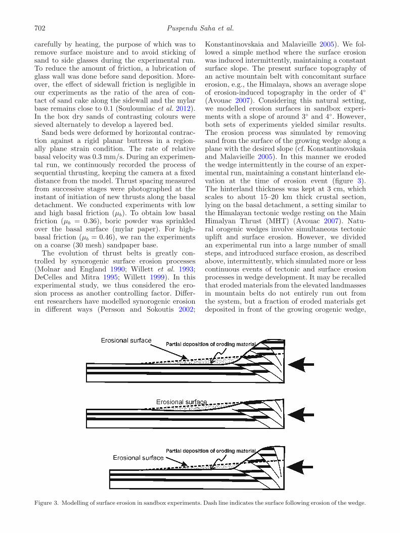
Figure 2. Schematic sketch of the laboratory set-up for sandbox experiments (not in scale).
following factors: basal friction (μb), surface slope(α) and basal slope (β) of the wedge. Based onthe experimental findings, we present a detailedaccount of factors controlling these three stylesof thrust progression, and suggest that theycan be used as potential indicators of geologicalconditions.
2. Experimental method
Sandbox experiments were performed employingthe conventional method for simulation of mono-vergent thrust wedges (Mulugeta and Koyi 1987,1992; Mulugeta 1988; Liu et al. 1992; Marshak andWilkerson 1992; Mandal et al. 1997; Agarwal andAgarwal 2002; Bose et al. 2009). Models were pre-pared with dry non-cohesive natural sand (meangrain size ∼500 μm). The model materials have
frictional properties satisfying the Coulomb theory(Dahlen et al. 1984) and can be used as analoguesof upper crustal rocks. The sandmass was chosenwith a bulk density ρ ∼ 1.6 gm/cm3 and internalco-efficient of friction, μ, was measured and foundto be 0.57 and the cohesion, C0 = 20 Pa. Earlierexperiments also suggest that loose sand materialsprovide a better approximation for scaled modelexperiments for large-scale brittle deformations inthe uppermost crust (Davis et al. 1983; Mulugeta1988; Liu et al. 1992; Mandal et al. 1997). Themethod of model preparation was similar to thatused in earlier studies (Davis et al. 1983; Mulugeta1988; Liu et al. 1992; Koyi 1995; Mandal et al.1997; Lujan et al. 2003; Yamada et al. 2006; Boseet al. 2009). The sandbox apparatus consisted ofa 100 cm long and 25 cm wide glass-sided walls,resting upon a conveyor belt (figure 2). The fourside glasses of the sandbox were cleaned and dried
702 Puspendu Saha et al.
carefully by heating, the purpose of which was toremove surface moisture and to avoid sticking ofsand to side glasses during the experimental run.To reduce the amount of friction, a lubrication ofglass wall was done before sand deposition. More-over, the effect of sidewall friction is negligible inour experiments as the ratio of the area of con-tact of sand cake along the sidewall and the mylarbase remains close to 0.1 (Souloumiac et al. 2012).In the box dry sands of contrasting colours weresieved alternately to develop a layered bed.
Sand beds were deformed by horizontal contrac-tion against a rigid planar buttress in a region-ally plane strain condition. The rate of relativebasal velocity was 0.3 mm/s. During an experimen-tal run, we continuously recorded the process ofsequential thrusting, keeping the camera at a fixeddistance from the model. Thrust spacing measuredfrom successive stages were photographed at theinstant of initiation of new thrusts along the basaldetachment. We conducted experiments with lowand high basal friction (μb). To obtain low basalfriction (μb = 0.36), boric powder was sprinkledover the basal surface (mylar paper). For high-basal friction (μb = 0.46), we ran the experimentson a coarse (30 mesh) sandpaper base.
The evolution of thrust belts is greatly con-trolled by synorogenic surface erosion processes(Molnar and England 1990; Willett et al. 1993;DeCelles and Mitra 1995; Willett 1999). In thisexperimental study, we thus considered the ero-sion process as another controlling factor. Differ-ent researchers have modelled synorogenic erosionin different ways (Persson and Sokoutis 2002;
Konstantinovskaia and Malavieille 2005). We fol-lowed a simple method where the surface erosionwas induced intermittently, maintaining a constantsurface slope. The present surface topography ofan active mountain belt with concomitant surfaceerosion, e.g., the Himalaya, shows an average slopeof erosion-induced topography in the order of 4◦
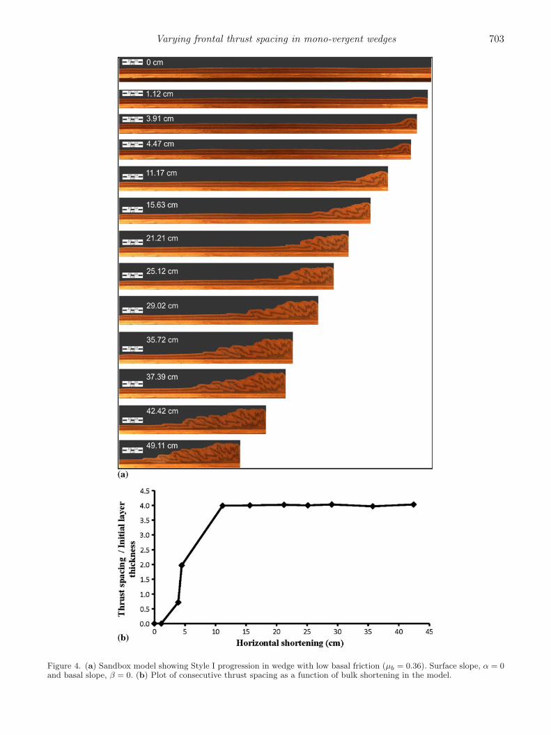
(Avouac 2007). Considering this natural setting,we modelled erosion surfaces in sandbox experi-ments with a slope of around 3◦ and 4◦. However,both sets of experiments yielded similar results.The erosion process was simulated by removingsand from the surface of the growing wedge along aplane with the desired slope (cf. Konstantinovskaiaand Malavieille 2005). In this manner we erodedthe wedge intermittently in the course of an exper-imental run, maintaining a constant hinterland ele-vation at the time of erosion event (figure 3).The hinterland thickness was kept at 3 cm, whichscales to about 15–20 km thick crustal section,lying on the basal detachment, a setting similar tothe Himalayan tectonic wedge resting on the MainHimalyan Thrust (MHT) (Avouac 2007). Natu-ral orogenic wedges involve simultaneous tectonicuplift and surface erosion. However, we dividedan experimental run into a large number of smallsteps, and introduced surface erosion, as describedabove, intermittently, which simulated more or lesscontinuous events of tectonic and surface erosionprocesses in wedge development. It may be recalledthat eroded materials from the elevated landmassesin mountain belts do not entirely run out fromthe system, but a fraction of eroded materials getdeposited in front of the growing orogenic wedge,
Figure 3. Modelling of surface erosion in sandbox experiments. Dash line indicates the surface following erosion of the wedge.
Varying frontal thrust spacing in mono-vergent wedges 703
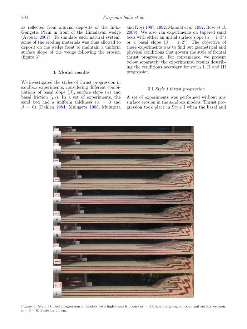
Figure 4. (a) Sandbox model showing Style I progression in wedge with low basal friction (μb = 0.36). Surface slope, α = 0and basal slope, β = 0. (b) Plot of consecutive thrust spacing as a function of bulk shortening in the model.
704 Puspendu Saha et al.
as reflected from alluvial deposits of the Indo-Gangetic Plain in front of the Himalayan wedge(Avouac 2007). To simulate such natural system,some of the eroding materials was thus allowed todeposit on the wedge front to maintain a uniformsurface slope of the wedge following the erosion(figure 3).
3. Model results
We investigated the styles of thrust progression insandbox experiments, considering different combi-nations of basal slope (β), surface slope (α) andbasal friction (μb). In a set of experiments, thesand bed had a uniform thickness (α = 0 andβ = 0) (Dahlen 1984; Mulugeta 1988; Mulugeta
and Koyi 1987, 1992; Mandal et al. 1997; Bose et al.2009). We also ran experiments on tapered sandbeds with either an initial surface slope (α = 1–3◦)or a basal slope (β = 1–2◦). The objective ofthese experiments was to find out geometrical andphysical conditions that govern the style of frontalthrust progression. For convenience, we presentbelow separately the experimental results describ-ing the conditions necessary for styles I, II and IIIprogression.
3.1 Style I thrust progression
A set of experiments was performed without anysurface erosion in the sandbox models. Thrust pro-gression took place in Style I when the basal and
Figure 5. Style I thrust progression in models with high basal friction (μb = 0.46), undergoing concomitant surface erosion.α = β = 0. Scale bar: 1 cm.
Varying frontal thrust spacing in mono-vergent wedges 705
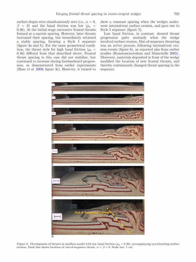
surface slopes were simultaneously zero (i.e., α = 0,β = 0) and the basal friction was low (μb ∼0.36). At the initial stage successive frontal thrustsformed at a narrow spacing. However, later thrustsincreased their spacing, but immediately attaineda stable spacing, forming a Style I sequence(figure 4a and b). For the same geometrical condi-tion, the thrust style for high basal friction (μb ∼0.46) differed from that described above. Frontalthrust spacing in this case did not stabilize, butcontinued to increase during forelandward progres-sion, as demonstrated from earlier experiments(Bose et al. 2009; figure 3c). However, it turned to
show a constant spacing when the wedges under-went intermittent surface erosion, and gave rise toStyle I sequence (figure 5).
Low basal friction, in contrast, showed thrustprogression quite unsteady when the wedgeinvolved surface erosion. Out-of-sequence thrustingwas an active process, following intermittent ero-sion events (figure 6), as reported also from earlierstudies (Konstantinovskaia and Malavieille 2005).Moreover, materials deposited in front of the wedgemodified the location of new frontal thrusts, andthereby continuously changed thrust spacing in thesequence.
Figure 6. Development of thrusts in sandbox model with low basal friction (μb = 0.36), accompanying syn-thrusting surfaceerosion. Dash line shows location of out-of-sequence thrust. α = β = 0. Scale bar: 1 cm.
706 Puspendu Saha et al.
Different conditions of Style I thrust progressionare summarized in table 1.
3.2 Style II thrust progression
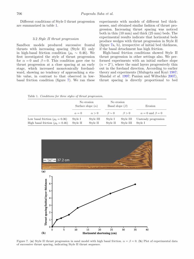
Sandbox models produced successive frontalthrusts with increasing spacing (Style II) onlyin high-basal friction condition (μb ∼ 0.46). Wefirst investigated the style of thrust progressionfor α = 0 and β = 0. This condition gave rise tothrust progression at a close spacing at an earlystage, which increased monotonically foreland-ward, showing no tendency of approaching a sta-ble value, in contrast to that observed in low-basal friction condition (figure 7). We ran these
experiments with models of different bed thick-nesses, and obtained similar fashion of thrust pro-gression. Increasing thrust spacing was noticedboth in thin (10 mm) and thick (25 mm) beds. Theexperimental results indicate that horizontal bedsproduce wedges with thrust progression in Style II(figure 7a, b), irrespective of initial bed thickness,if the basal detachment has high friction.
High-basal friction conditions showed Style IIthrust progression in other settings also. We per-formed experiments with an initial surface slope(α = 2◦), where the sand layers progressively thinout in the foreland direction. According to earliertheory and experiments (Mulugeta and Koyi 1987;Mandal et al. 1997; Panian and Wiltschko 2007),thrust spacing is directly proportional to bed
Table 1. Conditions for three styles of thrust progression.
No erosion No erosion
Surface slope (α) Basal slope (β) Erosion
α = 0 α > 0 β ∼ 0 β > 0 α = 0 and β = 0
Low basal friction (μb = 0.36) Style I Style III Style I Style III Unsteady progression
High basal friction (μb = 0.46) Style II Style II Style II Style III Style I
Figure 7. (a) Style II thrust progression in sand model with high basal friction. α = β = 0. (b) Plot of experimental dataof successive thrust spacing, indicating Style II thrust sequence.
Varying frontal thrust spacing in mono-vergent wedges 707
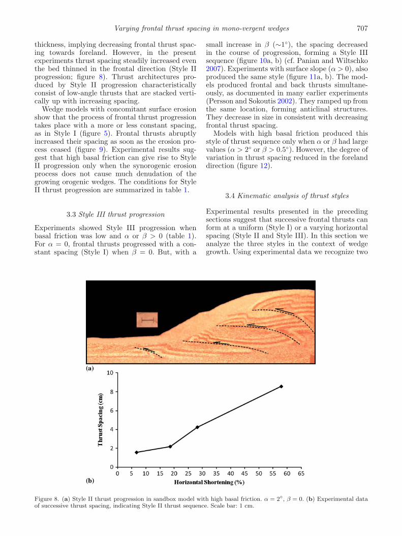
thickness, implying decreasing frontal thrust spac-ing towards foreland. However, in the presentexperiments thrust spacing steadily increased eventhe bed thinned in the frontal direction (Style IIprogression; figure 8). Thrust architectures pro-duced by Style II progression characteristicallyconsist of low-angle thrusts that are stacked verti-cally up with increasing spacing.
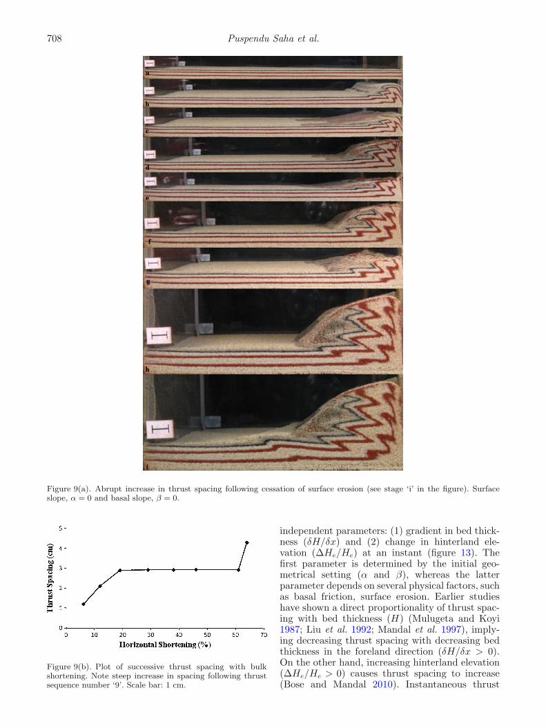
Wedge models with concomitant surface erosionshow that the process of frontal thrust progressiontakes place with a more or less constant spacing,as in Style I (figure 5). Frontal thrusts abruptlyincreased their spacing as soon as the erosion pro-cess ceased (figure 9). Experimental results sug-gest that high basal friction can give rise to StyleII progression only when the synorogenic erosionprocess does not cause much denudation of thegrowing orogenic wedges. The conditions for StyleII thrust progression are summarized in table 1.
3.3 Style III thrust progression
Experiments showed Style III progression whenbasal friction was low and α or β > 0 (table 1).For α = 0, frontal thrusts progressed with a con-stant spacing (Style I) when β = 0. But, with a
small increase in β (∼1◦), the spacing decreasedin the course of progression, forming a Style IIIsequence (figure 10a, b) (cf. Panian and Wiltschko2007). Experiments with surface slope (α > 0), alsoproduced the same style (figure 11a, b). The mod-els produced frontal and back thrusts simultane-ously, as documented in many earlier experiments(Persson and Sokoutis 2002). They ramped up fromthe same location, forming anticlinal structures.They decrease in size in consistent with decreasingfrontal thrust spacing.
Models with high basal friction produced thisstyle of thrust sequence only when α or β had largevalues (α > 2◦ or β > 0.5◦). However, the degree ofvariation in thrust spacing reduced in the forelanddirection (figure 12).
3.4 Kinematic analysis of thrust styles
Experimental results presented in the precedingsections suggest that successive frontal thrusts canform at a uniform (Style I) or a varying horizontalspacing (Style II and Style III). In this section weanalyze the three styles in the context of wedgegrowth. Using experimental data we recognize two
Figure 8. (a) Style II thrust progression in sandbox model with high basal friction. α = 2◦, β = 0. (b) Experimental dataof successive thrust spacing, indicating Style II thrust sequence. Scale bar: 1 cm.
708 Puspendu Saha et al.
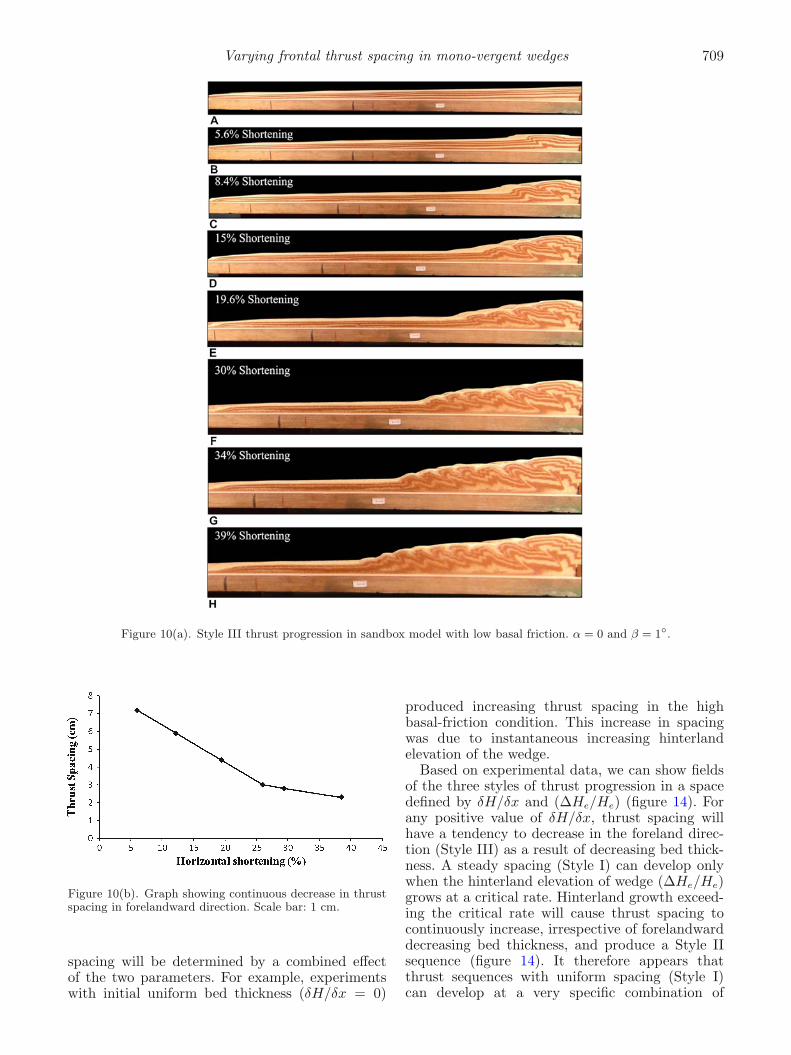
Figure 9(a). Abrupt increase in thrust spacing following cessation of surface erosion (see stage ‘i’ in the figure). Surfaceslope, α = 0 and basal slope, β = 0.
Figure 9(b). Plot of successive thrust spacing with bulkshortening. Note steep increase in spacing following thrustsequence number ‘9’. Scale bar: 1 cm.
independent parameters: (1) gradient in bed thick-ness (δH/δx) and (2) change in hinterland ele-vation (ΔHe/He) at an instant (figure 13). Thefirst parameter is determined by the initial geo-metrical setting (α and β), whereas the latterparameter depends on several physical factors, suchas basal friction, surface erosion. Earlier studieshave shown a direct proportionality of thrust spac-ing with bed thickness (H) (Mulugeta and Koyi1987; Liu et al. 1992; Mandal et al. 1997), imply-ing decreasing thrust spacing with decreasing bedthickness in the foreland direction (δH/δx > 0).On the other hand, increasing hinterland elevation(ΔHe/He > 0) causes thrust spacing to increase(Bose and Mandal 2010). Instantaneous thrust
Varying frontal thrust spacing in mono-vergent wedges 709
Figure 10(a). Style III thrust progression in sandbox model with low basal friction. α = 0 and β = 1◦.
Figure 10(b). Graph showing continuous decrease in thrustspacing in forelandward direction. Scale bar: 1 cm.
spacing will be determined by a combined effectof the two parameters. For example, experimentswith initial uniform bed thickness (δH/δx = 0)
produced increasing thrust spacing in the highbasal-friction condition. This increase in spacingwas due to instantaneous increasing hinterlandelevation of the wedge.
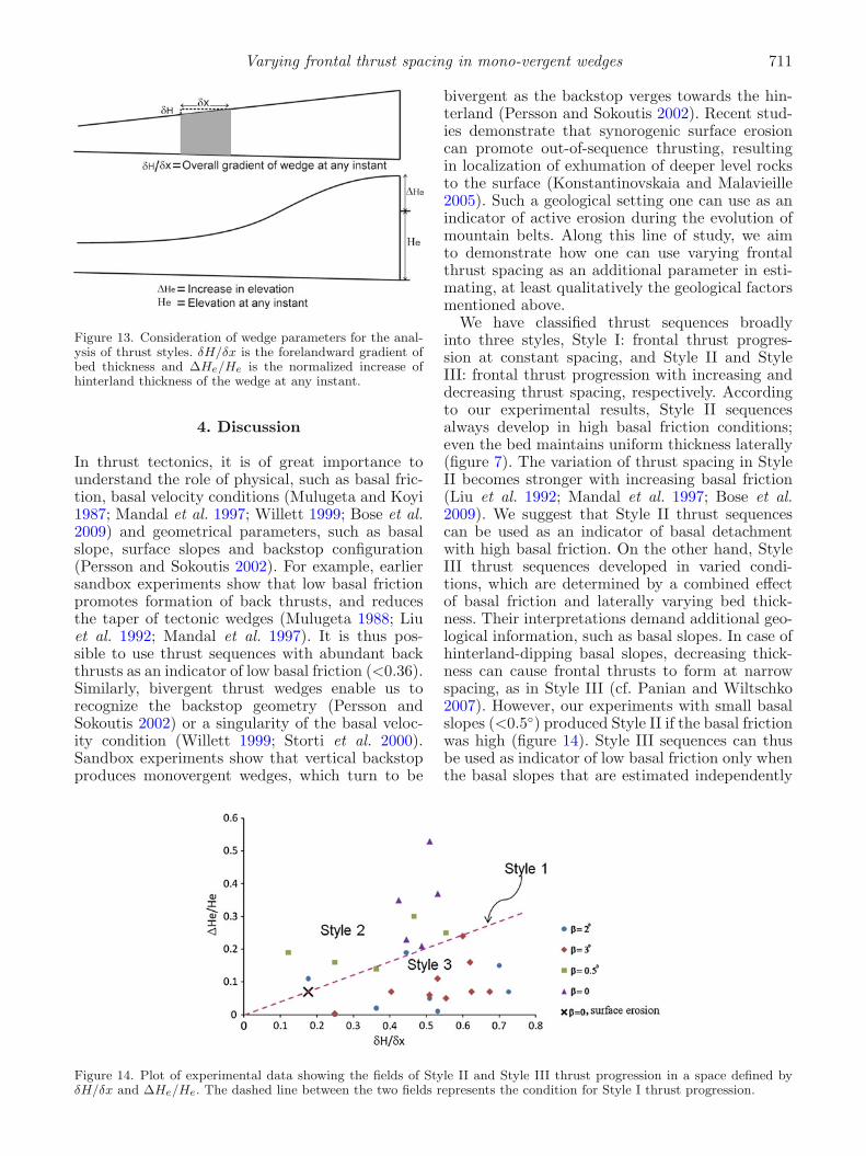
Based on experimental data, we can show fieldsof the three styles of thrust progression in a spacedefined by δH/δx and (ΔHe/He) (figure 14). Forany positive value of δH/δx, thrust spacing willhave a tendency to decrease in the foreland direc-tion (Style III) as a result of decreasing bed thick-ness. A steady spacing (Style I) can develop onlywhen the hinterland elevation of wedge (ΔHe/He)grows at a critical rate. Hinterland growth exceed-ing the critical rate will cause thrust spacing tocontinuously increase, irrespective of forelandwarddecreasing bed thickness, and produce a Style IIsequence (figure 14). It therefore appears thatthrust sequences with uniform spacing (Style I)can develop at a very specific combination of
710 Puspendu Saha et al.
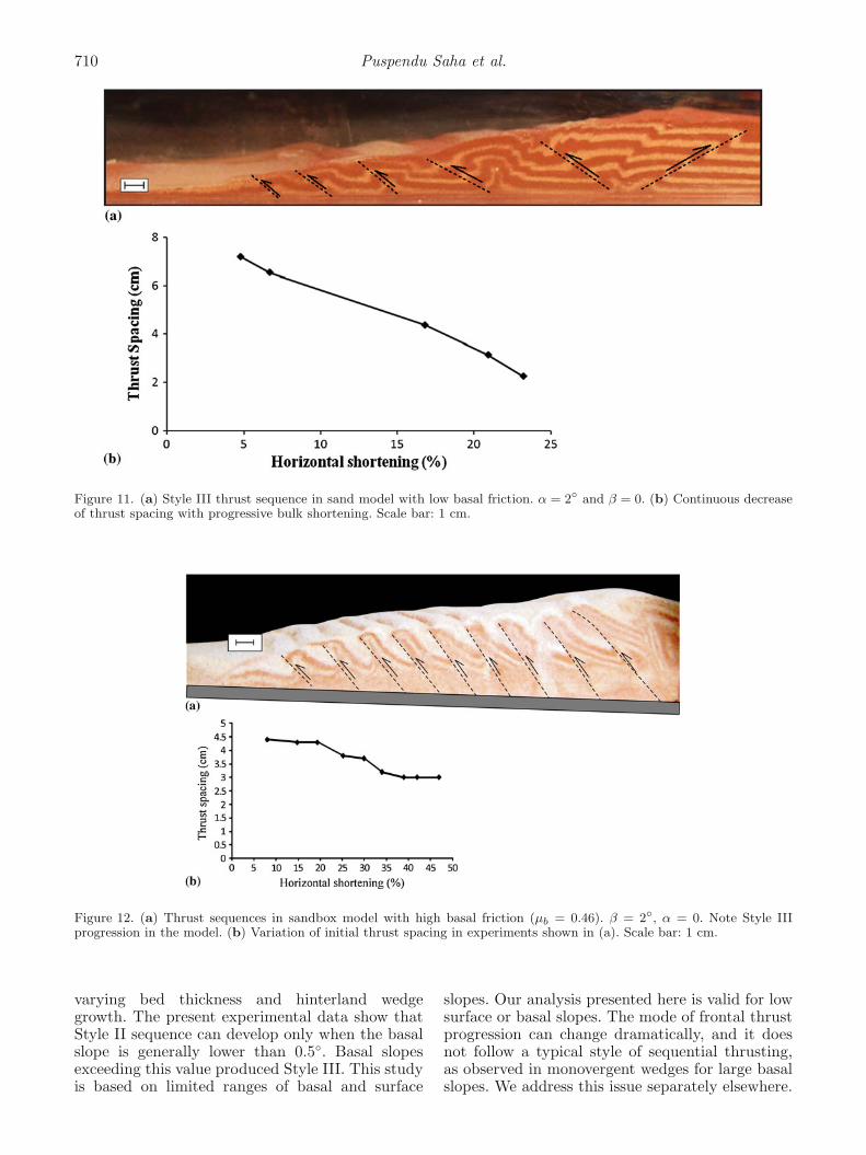
Figure 11. (a) Style III thrust sequence in sand model with low basal friction. α = 2◦ and β = 0. (b) Continuous decreaseof thrust spacing with progressive bulk shortening. Scale bar: 1 cm.
Figure 12. (a) Thrust sequences in sandbox model with high basal friction (μb = 0.46). β = 2◦, α = 0. Note Style IIIprogression in the model. (b) Variation of initial thrust spacing in experiments shown in (a). Scale bar: 1 cm.
varying bed thickness and hinterland wedgegrowth. The present experimental data show thatStyle II sequence can develop only when the basalslope is generally lower than 0.5◦. Basal slopesexceeding this value produced Style III. This studyis based on limited ranges of basal and surface
slopes. Our analysis presented here is valid for lowsurface or basal slopes. The mode of frontal thrustprogression can change dramatically, and it doesnot follow a typical style of sequential thrusting,as observed in monovergent wedges for large basalslopes. We address this issue separately elsewhere.
Varying frontal thrust spacing in mono-vergent wedges 711
Figure 13. Consideration of wedge parameters for the anal-ysis of thrust styles. δH/δx is the forelandward gradient ofbed thickness and ΔHe/He is the normalized increase ofhinterland thickness of the wedge at any instant.
4. Discussion
In thrust tectonics, it is of great importance tounderstand the role of physical, such as basal fric-tion, basal velocity conditions (Mulugeta and Koyi1987; Mandal et al. 1997; Willett 1999; Bose et al.2009) and geometrical parameters, such as basalslope, surface slopes and backstop configuration(Persson and Sokoutis 2002). For example, earliersandbox experiments show that low basal frictionpromotes formation of back thrusts, and reducesthe taper of tectonic wedges (Mulugeta 1988; Liuet al. 1992; Mandal et al. 1997). It is thus pos-sible to use thrust sequences with abundant backthrusts as an indicator of low basal friction (<0.36).Similarly, bivergent thrust wedges enable us torecognize the backstop geometry (Persson andSokoutis 2002) or a singularity of the basal veloc-ity condition (Willett 1999; Storti et al. 2000).Sandbox experiments show that vertical backstopproduces monovergent wedges, which turn to be
bivergent as the backstop verges towards the hin-terland (Persson and Sokoutis 2002). Recent stud-ies demonstrate that synorogenic surface erosioncan promote out-of-sequence thrusting, resultingin localization of exhumation of deeper level rocksto the surface (Konstantinovskaia and Malavieille2005). Such a geological setting one can use as anindicator of active erosion during the evolution ofmountain belts. Along this line of study, we aimto demonstrate how one can use varying frontalthrust spacing as an additional parameter in esti-mating, at least qualitatively the geological factorsmentioned above.
We have classified thrust sequences broadlyinto three styles, Style I: frontal thrust progres-sion at constant spacing, and Style II and StyleIII: frontal thrust progression with increasing anddecreasing thrust spacing, respectively. Accordingto our experimental results, Style II sequencesalways develop in high basal friction conditions;even the bed maintains uniform thickness laterally(figure 7). The variation of thrust spacing in StyleII becomes stronger with increasing basal friction(Liu et al. 1992; Mandal et al. 1997; Bose et al.2009). We suggest that Style II thrust sequencescan be used as an indicator of basal detachmentwith high basal friction. On the other hand, StyleIII thrust sequences developed in varied condi-tions, which are determined by a combined effectof basal friction and laterally varying bed thick-ness. Their interpretations demand additional geo-logical information, such as basal slopes. In case ofhinterland-dipping basal slopes, decreasing thick-ness can cause frontal thrusts to form at narrowspacing, as in Style III (cf. Panian and Wiltschko2007). However, our experiments with small basalslopes (<0.5◦) produced Style II if the basal frictionwas high (figure 14). Style III sequences can thusbe used as indicator of low basal friction only whenthe basal slopes that are estimated independently
Figure 14. Plot of experimental data showing the fields of Style II and Style III thrust progression in a space defined byδH/δx and ΔHe/He. The dashed line between the two fields represents the condition for Style I thrust progression.
712 Puspendu Saha et al.
from geological or seismic sections, are found to below. This criterion will not apply for settings withlarge basal slopes.
Style I thrust progression was observed in earliersandbox experiments (Mulugeta and Koyi 1987;Liu et al. 1992; Bose et al. 2009). Our experimen-tal findings suggest that this style can develop invaried conditions, the interpretation of which isnot straight forward. However, it can be shownuseful to consider Style I thrust sequences as apotential proxy of specific geological conditions.For example, orogenic belts with little or no basaland surface slopes can show Style I progressionunder both low and high basal friction (figures 4and 5). We can, however, recognize low basal fric-tion conditions, considering back thrusts in thesequence. Their absence would indicate high basalfriction. Style I can develop in high basal frictiononly when there is synorogenic surface erosion, theeffects of which need to be recognized indepen-dently by using some geological criteria, such aslocalization of exhumation of deep crustal materi-als (Beaumont et al. 2001; Konstantinovskaia andMalavieille 2005).
Several natural fold-and-thrust belts occur on aductile base, such as evaporites (Philippe 1994).In such settings, the mechanical coupling betweenthe overlying brittle layer and the ductile base isthe most crucial factor in controlling the progres-sion behaviour of thrusts (Smit et al. 2003). How-ever, the effect of brittle–ductile coupling differsfrom that of frictional base considered in this study.Frontal thrust progression in case of frictional basealways occurs steadily in the foreland directionunless there is a concomitant erosional activity. Onthe other hand, the progression behaviour wouldbe much more complex when the basal resistanceis controlled by brittle–ductile coupling. Strongbrittle-coupling can only give rise to a regular fore-landward thrust progression, as in the case of fric-tional base. The progression turns to be oscillatoryas the coupling becomes weak (Smit et al. 2003).
We used models with a uniform surface slope toinvestigate how the style of thrust progression canchange depending upon the inherent topographicslopes in convergent zones. However, the surfacetopography can be much more complex in naturalsituations, exerting an additional effect on locationof frontal thrust and their subsequent propagation(Marques and Cobbold 2002). In a recent study,Panian and Wiltschko (2004) have shown that thelocation of thrusting is also guided by the topo-graphy formed by earlier thrust ramping. Thus, thespacing of successive thrusts may be controlled notonly by the overall slope, but their local variations,such as basal friction, synorogenic erosion and pos-sibly, also due to variations in pore fluid pressurewhich we have not tested. Further, experimental
investigations are required to study the style offrontal thrust progression as a function of later-ally varying surface topography. The present resultgives a first hand idea about the effect of surfaceslope on thrust progression. We have consideredbasal slope as another parameter in the experi-ments, which was varied between 0 and 2◦. Naturalfold-and-thrust belts can have much large basalslopes (Leech et al. 2005; Bollinger et al. 2006).The results of our study are, thus, applicable totectonic wedges with very low basal slopes.
There are some other limitations in this study.
• Models considered in the experiments were rheo-logically homogeneous laterally as well as depth-wise. On the other hand, the crustal rheology canvary significantly spatially, and influence locationof thrust (e.g., Beaumont et al. 2001).
• All the experiments were conducted with a verti-cal buttress. However, thrust styles, particularlythose localize in the hinterland part can varydepending upon buttress geometry (Persson andSokoutis 2002).
• Fluid pressure may have significant control indevelopment of thrust wedges (Cobbold and Cas-tro 1999; Mourgues and Cobbold 2006), whichhas not been considered in our experiments.
5. Conclusions
• Frontal thrusts in orogenic wedges can progressin three styles: Style I – progression with uni-form thrust spacing; Style II and III – progressionwith increasing and decreasing thrust spacing,respectively.
• Style II thrust progression occurs only whenthe basal friction is high. It can be used as anindicator of high basal friction.
• Thrust progression takes place in Style III if theconvergent belts have significant basal slopes,irrespective of basal friction.
• Style I thrust sequences are indicators of thefollowing initial conditions: (1) horizontal basaldecollement with low friction without any initialsurface slope and surface erosion, or (2) horizon-tal basal decollement with high basal friction andsurface erosion.
• Surface erosion causes unsteadiness in frontalthrust progression, involving out-of-sequencethrusting when the basal friction is low.
Acknowledgements
The authors are grateful to Prof. SomnathDasgupta for giving them an outline for revisingthe manuscript and two anonymous reviewers for
Varying frontal thrust spacing in mono-vergent wedges 713
their insightful reviews and many constructive sug-gestions for improvement of the manuscript. Theyare grateful to the DST (Project No. SR/S4/ES-461/2009), India for their support. Infrastructurefacilities granted by the UGC, India are gratefullyacknowledged.
References
Agarwal K K and Agarwal G K 2002 Analogue sandboxmodels of thrust wedges with variable basal friction;Gondwana Res. 5 641–647.
Avouac J P 2007 Dynamic processes in extensional andcompressional settings – mountain building: From earth-quakes to geological deformation; Treatise on Geophys. 6377–439.
Avouac J P and Burov E B 1996 Erosion as a driving mech-anism of intracontinental mountain growth; J. Geophys.Res. 101 17,747–17,769.
Beaumont C, Jamieson R A, Nguyen M H and Lee B2001 Himalayan tectonics explained by extrusion of alow-viscosity crustal channel coupled to focused surfacedenudation; Nature 414 738–742.
Bollinger L, Henry P and Avouac J P 2006 Mountain build-ing in the Nepal Himalaya: Thermal and kinematic model;Earth Planet. Sci. Lett. 244 58–71.
Bombalakis E G 1986 Thrust-fault mechanics and origin ofa frontal ramp; J. Struct. Geol. 8 281–290.
Bose S and Mandal N 2010 Interaction of surface ero-sion and sequential thrust progression: Implications onexhumation processes; J. Geol. Soc. India 75 338–344.
Bose S, Mandal N, Mukhopadhyay D K and Mishra P2009 An unstable kinematic state of the Himalayan tec-tonic wedge: Evidence from experimental thrust-spacingpatterns; J. Struct. Geol. 31 83–91.
Butler R W H 1992 Structural evolution of the westernChartreuse fold and thrust system, NW French Subalpinechains; In: Thrust Tectonics (ed.) McClay K R (London:Chapman and Hall), pp. 287–298.
Cello G and Nurr A 1988 Emplacement of foreland thrustsystems; Tectonics 7 261–272.
Chapple W M 1978 Mechanics of thin-skinned fold-and-thrust belts; Geol. Soc. Am. Bull. 89 1189–1198.
Cobbold P R and Castro L 1999 Fluid pressure and effectivestress in sandbox models; Tectonophys. 301(1) 1–19.
Dahlen F A 1984 Noncohesive critical coulomb wedges: Anexact solution; J. Geophys. Res. 89 10,125–10,133.
Dahlen F A, Suppe J and Davis D M 1984 Mechanics offold-and-thrust belts and accretionary wedges: CohesiveCoulomb theory; J. Geophys. Res. 89 10,087–10,101.
Davis D M and Engelder T 1985 The role of salt in fold-and-thrust belts; Tectonophys. 119 67–88.
Davis D M, Suppe J and Dahlen F A 1983 Mechanics of fold-and-thrust belts and accretionary wedges; J. Geophys.Res. 88 1153–1172.
DeCelles P G and Mitra G 1995 History of the Sevier oro-genic wedge in terms of critical taper models, northeastUtah and southwest Wyoming; Geol. Soc. Am. Bull. 107454–462.
DeCelles P G, Gehrels G E, Quade J and Ojha T P1998 Eocene–early Miocene foreland basin developmentand the history of Himalayan thrusting, far western andcentral Nepal; Tectonics 17 741–765.
Geiser P A 1988 Mechanisms of thrust propagation: Someexamples and implications for the analysis of overthrustterranes; J. Struct. Geol. 10 829–845.
Goff D F, Wiltschko D V and Fletcher R C 1996 Decolle-ment folding as a mechanism for thrust-ramp spacing;J. Geophys. Res. 101 11,341–11,352.
Gutscher M A, Kukowski N, Malavieille J and LallemandS 1998a Material transfer in accretionary wedges fromanalysis of a systematic series of analog experiments;J. Struct. Geol. 20 407–416.
Gutscher M A, Kukowski N, Malavieille and Lallemand S1998b Episodic imbricate thrusting and underthrusting:Analogue experiments and mechanical analysis applied tothe Alaskan accretionary wedge; J. Geophys. Res. 10310,161–10,176.
Hoth S 2006 Deformation, erosion and natural resourcesin continental collision zones. Insight from scaled sand-box simulations, STR 06/06, GeoForschungsZentrumPotsdam, Potsdam, Germany, 153p.
Hoth S, Adam J, Kukowski N and Oncken O 2006 Influenceof erosion on the kinematics of bivergent orogens. Resultsfrom scaled sandbox simulations; In: Tectonics, Climateand Landscape Evolution (eds) Willett S, Hovius N,Brandon M and Fisher D, GSA Special Paper 398,Penrose Conference Series, pp. 201–225.
Jadoon I A K, Lawrence R D and Lillie R J 1992 Bal-anced and retrodeformed geological cross-section from thefrontal Sulaiman Lobe, Pakistan: Duplex developmentin thick strata along the western margin of the IndianPlate; In: Thrust Tectonics (ed.) McClay K R (London:Chapman and Hall), pp. 343–356.
Knipe R J 1985 Footwall geometry and the rheology ofthrust sheets; J. Struct. Geol. 7 1–10.
Konstantinovskaia E and Malavieille J 2005 Erosion andexhumation in accretionary orogens: Experimental andgeological approaches; Geochem. Geophys. Geosys. 6Q02006, doi: 10.1029/2004GC000794, ISSN: 1525–2027.
Koons P O 1990 The two-sided orogen: Collision and erosionfrom the sandbox to the Southern Alps, New Zealand;Geology 18 679–682.
Koyi H 1995 Mode of internal deformation of sand wedges;J. Struct. Geol. 17 293–300.
Leech M L, Singh S, Jain A K, Klemperer S L andManickavasagam R M 2005 The onset of India–Asia con-tinental collision: Early, steep subduction required by thetiming of UHP metamorphism in the western Himalaya;Earth Planet. Sci. Lett. 234 83–97.
Liu H, McClay K R and Powell D 1992 Physical models ofthrust wedges; In: Thrust Tectonics (ed.) McClay K R(London: Chapman and Hall), pp. 71–81.
Lujan M, Storti F, Balanya J C, Crespo-Blanc A andRossetti F 2003 Role of decollement material with differ-ent rheological properties in the structure of the Aljibethrust imbricate (Flysch Trough, Gibraltar Arc): An ana-logue modelling approach; J. Struct. Geol. 25 867–881.
Malavieille J 1984 Mode’lisation expe’rimentale deschevauchements imbrique’s: Application aux chaines demontagnes; Bull. Soc. Geol. Fr. 7 129–138.
Mandal N, Chattopadhyay A and Bose S 1997 Imbricatethrust spacing: Experimental and theoretical analyses;In: Evolution of Geological Structures in Micro- to Macro-scales (ed.) Sengupta S (London: Chapman and Hall),pp. 143–165.
Marques F O and Cobbold P R 2002 Topography as a majorfactor in the development of arcuate thrust belts: Insightsfrom sandbox experiments; Tectonophys. 348 247–268.
Marshak S and Wilkerson M S 1992 Effect of overbur-den thickness on thrust belt geometry and development;Tectonics 11 560–566.
Molnar P and England P 1990 Late Cenozoic uplift ofmountain-ranges and global climate change – chicken oregg; Nature 346(6279) 29–34.
714 Puspendu Saha et al.
Mourgues R and Cobbold P R 2006 Thrust wedges and fluidoverpressures: Sandbox models involving pore fluids; J.Geophys. Res. 111 B05404, doi: 10.1029/2004JB003441.
Mulugeta G 1988 Modeling the geometry of Coulomb thrustwedges; J. Struct. Geol. 10 847–859.
Mulugeta G and Koyi H A 1987 Three dimensional geome-try and kinematics of experimental piggyback thrusting;Geology 15 1052–1056.
Mulugeta G and Koyi H 1992 Episodic accretion and strainpartitioning in a model sand wedge; Tectonophys. 202319–333.
Panian J and Wiltschko D V 2004 Ramp initiation in athrust wedge; Nature 427 624–627.
Panian J and Wiltschko D V 2007 Ramp initiation and spac-ing in a homogeneous thrust wedge; J. Geophys. Res. 112B05417, doi: 10.1029/2004JB003596.
Persson K S and Sokoutis D 2002 Analogue models of oro-genic wedges controlled by erosion; Tectonophys. 356323–336.
Philippe Y 1994 Transfer zone in the southern JuraThrust Belt (eastern France): Geometry, developmentand comparison with analogue model experiments; In:Hydrocarbon and Petroleum Geology of France (ed.) MascleA, Eur. Assoc. Pet. Geosci. Spec. Publ. 4 327–346.
Platt J P 1986 The mechanics of frontal imbrication, a first-order analysis; Geol. Rundsch 77 577–589.
Schott B and Koyi H A 2001 Estimating basal friction inaccretionary wedges from the geometry and spacing offrontal faults; Earth Planet. Sci. Lett. 194 221–227.
Smit J H W, Brun J P and Sokoutis D 2003 Defor-mation of brittle–ductile thrust wedges in experi-ments and nature; J. Geophys. Res. 108 B102480, doi:10.1029/2002JB002190.
Souloumiac P, Mailot B and Leroy Y M 2012 Bias due toside wall friction in sandbox apparatus; J. Struct. Geol.35 90–101.
Srivastava P and Mitra G 1994 Thrust geometries and deepstructure of the Outer and Lesser Himalaya, Kumaonand Garhwal (India): Implications for evolution of theHimalayan fold-and-thrust belt; Tectonics 13 89–109.
Storti F, Francesco S and McClay K 2000 Synchronous andvelocity-partitioned thrusting and thrust polarity rever-sal in experimentally produced, doubly-vergent thrustwedges: implications for natural orogens; Tectonics 19(2)378–396.
Willett S D 1999 Orogeny and orography: The effects oferosion on the structure of mountain belts; J. Geophys.Res. 104 28,957–28,981.
Willett S D, Beaumont C and Fullsack P 1993 Mechanicalmodel for the tectonics of doubly vergent compressionalorogens; Geology 21 371–374.
Wiltschko D V and Eastman D B 1982 Role of basementwarps and faults in localizing thrust-fault ramps; Geol.Soc. Am. Memoir 158 177–190.
Yamada Y, Baba K and Matsuoka T 2006 Analogue andnumerical modeling of accretionary prisms with a decolle-ment in sediments; Geol. Soc. London Spec. Publ. 253169–183.
MS received 5 January 2012; revised 17 August 2012; accepted 4 December 2012