Classical Hydrodynamics for Analogue Spacetimes - Archive ...

Directional flank spreading at Mount Cameroonvolcano: Evidence from analogue modelingM. Kervyn1, B. van Wyk de Vries2, T. R. Walter3, M. S. Njome4, C. E. Suh4, and G. G. J. Ernst5
1Department of Geography, Earth System Science, Vrije Universiteit Brussel, Brussels, Belgium, 2Laboratoire Magma etVolcans, Université Blaise Pascal, Clermont-Ferrand, France, 3GFZ German Research Center for Geosciences, Potsdam,Germany, 4Department of Geology and Environmental Science, University of Buea, Buea, Cameroon, 5Department ofGeology and Soil Science, Ghent University, Gent, Belgium
Abstract Mount Cameroon is characterized by an elongated summit plateau, steep flanks, and topographicterraces around its base. Although some of these features can be accounted for by intrusion-induceddeformation, we here focus on the contribution of edifice-scale gravitational spreading in the structure ofMount Cameroon. We review the existing geological and geophysical data and morphostructural features ofMount Cameroon and surrounding sedimentary basins. Volcanic ridge gravitational spreading is then simulatedby scaled analogue models on which fault formation is recorded using digital image correlation. Three sets ofmodels are presented (i) models recorded in cross section (Type I), (ii) models recorded from above with auniform (Type IIa), and (iii) nonuniform ductile layer (Type IIb). Type I models illustrate the formation offaults accommodating summit subsidence and lower flank spreading. Type IIa models favor displacementperpendicular to the long axis, with formation of a summit graben and basal folds, but fail to reproduce thesteep flanks. Type IIb models investigate the effect of spatial variations in sediment thickness and/or propertiesconsistent with geological evidence. Directional spreading of the volcano’s central part perpendicular to thelong axis is accounted for by a sediment layer with restricted lateral extent and increasing thickness away fromthe volcano axis. The later model closely reproduces key features observed at Mount Cameroon: steep upperflanks are accounted for by enhanced lateral spreading of the lower flanks relative to the summit. The relevanceof these findings for understanding flank instabilities at large oceanic volcanoes is finally highlighted.
1. Introduction
High volcanoes are inherently unstable piles of poorly consolidated material, affected by deformationprocesses that contribute to limit the maximum height they can reach [e.g., Delaney, 1992; Borgia et al., 2000;Grosse et al., 2009]. Repetitive magmatic intrusions along volcanic rift zones and gravitational spreadingare recognized as the two main processes controlling internal structure and flank deformation at largevolcanoes [Le Corvec and Walter, 2009 and references therein], as documented at oceanic islands, e.g., Kilauea(Hawaii, USA) [e.g., Morgan et al., 2003] or Piton de la Fournaise (Reunion Island) [Oehler et al., 2005], largecontinental volcanoes, e.g., Etna (Sicily, Italy) [e.g., Borgia et al., 1992], and Martian shields [e.g.,McGovern andMorgan, 2009; Platz et al., 2011; Byrne et al., 2013, 2014]. In these studies, flank movements are thought to befacilitated by ductile layers below (i.e., marine or deltaic sediments) or within the volcanic edifice (i.e.,hydrothermally altered rocks).
Le Corvec and Walter [2009] investigated the structures and deformation induced by magmatic intrusionsalong a volcanic rift zone and by gravitational spreading in a volcanic ridge, and the strong coupling betweenthese two processes, using analogue models. They simulated the deformation of a half topographic ridgebetween two glass panes: this setting was required to simulate magmatic intrusion along a rift zone butprevented faults’ propagation from one flank of the ridge to the other below the summit. They illustrated thatboth processes are associated with flank deformation, but with contrasted structural features, and that theirrelative influences on the structural evolution of a volcano are difficult to differentiate. Flank gravitationalspreading is accommodated by an outward dipping listric fault, not always reaching the ridge summit, andassociated antithetic faults. Rift zone intrusions induce summit graben subsidence and the coherent outwarddisplacement of the flank along a subhorizontal decollement layer: this deformation was accompanied bylocalized steepening of the flank and shallow instability or thrusts and folds at the flank base, depending onthe depth of the intrusion [Le Corvec and Walter, 2009].
KERVYN ET AL. ©2014. American Geophysical Union. All Rights Reserved. 1
PUBLICATIONSJournal of Geophysical Research: Solid Earth
RESEARCH ARTICLE10.1002/2014JB011330
Special Section:Stress, Strain and MassChanges at Volcanoes
Key Points:• Mount Cameroonmorphology providesevidence of gravitational deformation
• Dynamics of the deformation isanalyzed through analogue models
• Directional flank spreading overnonuniform weak sedimentscontrols deformation
Supporting Information:• Readme• Figure S1• Figure S2
Correspondence to:M. Kervyn,[email protected]
Citation:Kervyn, M., B. van Wyk de Vries,T. R. Walter, M. S. Njome, C. E. Suh, andG. G. J. Ernst (2014), Directional flankspreading at Mount Cameroon volcano:Evidence from analogue modeling,J. Geophys. Res. Solid Earth, 119,doi:10.1002/2014JB011330.
Received 28 MAY 2014Accepted 22 SEP 2014Accepted article online 26 SEP 2014

In-depth understanding of deformation processes is essential for the interpretation of geophysical data, theassessment of risks associated with slope instabilities or to constrain the interactions between volcanostructures andmagmatic systems. Building on the results of Le Corvec andWalter [2009], we here focus on thedeformation dynamics and structures induced by gravitational spreading, using Mount Cameroon as anillustrative test case.
Mount Cameroon volcano is a 4095m high lava-dominated volcano built over weak sediments [Suh et al.,2001, 2003, 2008]. With a volume of ~1300 km3, it is one of the most voluminous continental volcanoestogether with Kilimanjaro (Tanzania) and Etna (Italy). Mount Cameroon’s morphology displays a broad andflat summit plateau, ~30° steep upper flanks, sharp slope breaks, and gently sloping terraces around its base[Gèze, 1943; Déruelle et al., 1987]. A number of deformation processes [Dzurisin, 2007] are expected to takeplace at Mount Cameroon: magmatic deformation was interpreted from interferometric synthetic apertureradar data for the 1999 and 2000 eruptions [Walter and Amelung, 2003]; tectonic faulting is consistent withthe elongation of Mount Cameroon along the Cameroon fracture line [Déruelle et al., 1987]; and gravity-driven mass movements was suggested by Mathieu et al. [2011] based on field investigation. This later studyproposed a model in which the long flanks of Mount Cameroon are laterally spreading and its summit issubsiding, as evidenced by thrusts and folds observed in underlying Miocene sediments.
Yet this conceptual model of volcano spreading, or the one of magmatic intrusion presented by Le Corvec andWalter [2009], are unable to fully account for the observed steep upper flanks, for local slope instabilities orfor the asymmetric distribution of thrust faults around the volcano. The continental and active tectonicsetting of Mount Cameroon is ideal to document the edifice-scale deformation structures, to investigateprocesses responsible for unusually steep slopes (i.e.,>20°) at other lava-dominated volcanoes [e.g., Rowland andGarbeil, 2000], and to unravel the potential influence of active tectonic structures on volcano deformation.
Building upon Le Corvec and Walter [2009] and Mathieu et al. [2011], the objective of this contribution is toinvestigate the deformation dynamics at Mount Cameroon and, specifically, to assess the contribution ofgravitational spreading to the current volcano morphology, including the steep unstable upper slopes. Wefirst review in details the geological setting and the volcano structure and morphology, as they provideessential constraints for the analogue models. Then we present new analogue experiments that simulate thegravitational spreading of a sand ridge over a ductile silicone layer. Models recorded in cross section (Type I)and from above (Type II) with varying ductile layer geometries are presented and analyzed with an imagecorrelation technique. We thereafter discuss if the dynamics of gravitational spreading is consistent with themorphology observed at Mount Cameroon and consider the contribution of magmatic intrusions to theoverall deformation dynamics.
2. Geological Setting
Mount Cameroon is the largest volcano within the Cameroon Volcanic Line (Figure 1a), a ~2000 km longalignment of Cenozoic alkaline intraplate volcanoes extending from the oceanic crust of the Gulf of Guinea tothe Adamawa Plateau in Tchad (Figure 1). The origin of the Cameroon Volcanic Line remains a matter ofdebate [e.g., Déruelle et al., 2007; Reusch et al., 2010; Gallacher and Bastow, 2012; Milelli et al., 2012].
Seismic and gravity studies of the Cameroon Volcanic Line suggest that magmatism in the Miocene inducedan asymmetric uplift of the oceanic crust by as much as 3 km [Meyers and Rosendahl, 1991;Meyers et al., 1998],and a ~1 km amplitude uplift in the continental sector of the Cameroon Volcanic Line, centered on theAdamawa plateau [e.g., Meyers and Rosendahl, 1991; Poudjom Djomani et al., 1997]. Reusch et al. [2010]showed this uplift to be associated with a linear low seismic velocity zone in the upper mantle. Hence, acrustal uplift, associated with reduced sediment deposition and/or increased erosion can also be expectedbelow Mount Cameroon, further enhanced by uplift caused by magma intrusions at the onset of volcanogrowth [Mathieu and van Wyk de Vries, 2009].
Mount Cameroon is located at the transition between oceanic crust and continental crust and overliessedimentary basins (see below). With seven confirmed eruptions in the twentieth century [e.g., Fitton et al.,1983; Suh et al., 2003; Bonne et al., 2008; Njome et al., 2008; Suh et al., 2008;Wantim et al., 2011, 2013], MountCameroon is themost active volcano of the Cameroon Volcanic Line. It is dominantly made up of overlappinglava flows of alkaline basalt composition, with a lesser but probably significant proportion of pyroclastic
Journal of Geophysical Research: Solid Earth 10.1002/2014JB011330
KERVYN ET AL. ©2014. American Geophysical Union. All Rights Reserved. 2
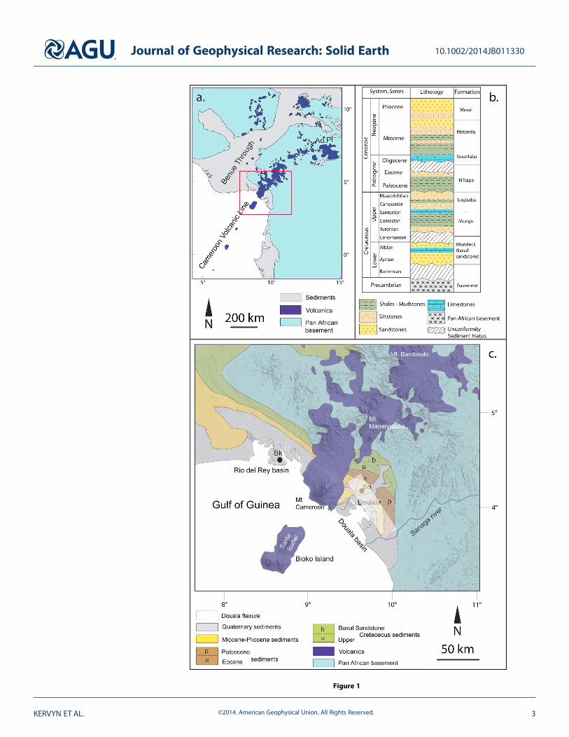
Figure 1
Journal of Geophysical Research: Solid Earth 10.1002/2014JB011330
KERVYN ET AL. ©2014. American Geophysical Union. All Rights Reserved. 3

cones and dyke intrusions along its central axis [Mathieu et al., 2011]. Volcano growth may have started1–3Ma ago [Hedberg, 1968;Marzoli et al., 2000;Wandji et al., 2009]. At its base, early stage lava flows of MountCameroon cover Miocene sediments which outcrop along topographic terraces (see below). Field evidencesuggests that these sediments were uplifted and deformed relative to the surrounding sedimentary basins[Hedberg, 1968; Meyers and Rosendahl, 1991; Mathieu et al., 2011].
The structure, geometry, and composition of sedimentary basins underlying volcanoes can affect theirstructure and deformation [Borgia et al., 2000]; we therefore here describe the characteristics of theunderlying sedimentary basins, with specific attention to weak sediment layers that can undergo ductiledeformation under gravitational loading. Mount Cameroon is built upon thick sediments, which havedeposited over Pan-African Mobile Belt crystalline and metamorphic rocks. To the east and NW of MountCameroon, the Douala and Rio del Rey sedimentary basins are observed, respectively. These basins are halfgrabens initiated during the Aptian-Albian (Figure 1c) [Benkhelil et al., 2002]. The two basins are bounded tothe north by a set N120°E striking listric faults, which have accommodated seaward basin deepening[Dumort, 1968; Reyre, 1984; Moreau et al., 1987; Benkhelil et al., 2002].
The basins’ stratigraphy encompasses Aptian to Pliocene fluvial and marine formations and Pleistocene deltasediments (Figures 1b and 1c). The Aptian-AlbianMundeck Formation is a 600m thick coarse fluvial sandstoneunit (i.e., basal sandstone, Figure 1b). The postrifting Upper CretaceousMungo-Logbaba Formation consists ofmarine siltstones with intercalated shallow limestones, marls, and shales (~500m thick, Figure 1b) [Regnoult,1986; Ponsard and Saugy, 1989; Meyers et al., 1996; Brownfield and Charpentier, 2006]. These Cretaceoussediments form a NW-SE trending outcrop located north of Mount Cameroon. More recent sedimentsgradually crop out further SW (Figure 1c).
In the Rio del Rey basin, Cretaceous sediments are unconformably overlain by Tertiary nonmarine sands, silts,and deltaic shales. In the Douala basin the Paleocene-Lower Eocene unit (N’Kapa Formation, >600m thick,Figure 1b) consists of thick organic-rich shales, marls, and calcareous sandstones, whereas Oligocene toMiocene deposits (Souellaba and Matanda Formations, ~1000m thick, Figure 1b) are mainly detritic gravelsand sandstones with intercalated plastic clay beds [Ponsard and Saugy, 1989; Brownfield and Charpentier,2006]. The post-Cretaceous stratigraphy does not correlate from the Douala to Rio del Rey basin across theCameroon Volcanic Line.
In both basins, weak sediment layers have been documented. Several shale beds are characterized byabnormal pressure interpreted as undercompaction where shale was not able to expel its interstitial waterafter desmectisation [Reyre, 1984]. This interpretation is based on observations in the onshore wells ofBomono, East of Mount Cameroon, at ~2200m depth toward the base of Lower Miocene deposits. Underhigh stress, these overpressured shales are highly mobile [Reyre, 1984]. This is consistent with diapiric rise ofshales, deforming overlying Mio-Pliocene deposits, observed in Bakassi M1 well in the Rio del Rey basin[Reyre, 1984] (Figure 1c).
The depth to the Pan-African basement increases nonlinearly southward. The most significant increase insediment thickness occurs along the Douala flexure directly north of Mount Cameroon, with depth-to-basementincreasing from 1 to 3–4 km over a 20 km distance (Figure 1) [Belmonte, 1966]. The amount of water-richductile shale beds also increases dramatically south of the flexure. Sediment thickness in the Douala and Rio delRey basin at the latitude of Mount Cameroon is estimated to vary from 3 to 5 km from NE to SW [Ponsard andSaugy, 1989].
The Rio del Rey and Douala basins may have been separated by prevolcanism regional uplift in theMiocene [Meyers and Rosendahl, 1991] so that a thinner sediment package is to be expected above theuplifted area. This is consistent with stratigraphic observations at the base of Mount Cameroon that
Figure 1. (a) Location of study area (red rectangle) and extent of the volcanics from the Cameroon Volcanic Line in WestAfrica (Ad.Pl.: Adamawa Plateau). (b) Generalized stratigraphic log of NW part of Douala sedimentary basin (adapted fromRegnoult [1986], Meyers et al. [1996], and Brownfield and Charpentier [2006]). (c) Schematic geological map of MountCameroon and surrounding sedimentary basins, with shaded relief of the SRTM DEM in background (adapted fromLe Maréchal [1975], Chiarelli [1976], Regnoult [1986], and Brownfield and Charpentier [2006]). The Douala flexure, characterizedby a stepwise deepening of the sedimentary in the south-west direction is located by a white shading, according toBelmonte [1966]. Bk: Bakassi M1 well; Bo: Bomono well.
Journal of Geophysical Research: Solid Earth 10.1002/2014JB011330
KERVYN ET AL. ©2014. American Geophysical Union. All Rights Reserved. 4

indicate that Mount Cameroon’s volcanic products intrude and overlie ~800m of sedimentary deposits[Dumort, 1968; Hedberg, 1968; Regnoult, 1986].
In summary, Mount Cameroon is a large basaltic volcano built up over the last million years above a 3–5 kmthick sequence of Cretaceous to Miocene mechanically weak sediments, characterized by mobile shale bedsfound at 2 to 4 km depth away from the Cameroon Volcanic Line axis. Type and thickness of sedimentsrapidly evolve from NE to SW. Crustal uplift and volcano growth reduced sediment deposition along the lineaxis and enhanced sediment accumulation off axis.
3. Volcano Morphology Analysis
Using the 30m X-band Shuttle Radar Topography Mission-(SRTM) digital elevation model and comparing itwith field data from Mathieu et al. [2011], we hereafter review the surface morphology (i.e., slopes, ventspatial distribution, fissures, or lineaments; Figures 2–4) and geology of MC in order to describe thestructural map of this volcano. Together with the geological setting, this section provides constraints toassess the applicability of the analogue models to Mount Cameroon.
3.1. Terrain Slope
Mount Cameroon is a large volcano, elongated NE-SW, i.e., it has two long flanks, facing SE and NW, and twoshort flanks, facing NE and SW. It has a well defined volcanic rift zone marked by the alignment of eruptive
Figure 2. (a) Shaded relief (Sun azimuth: 315°N, elevation 45°) with location of main cities and (b) slope distribution of Mount Cameroon extracted from SRTM DEMs—combining the 1 and 3 arc second resolution—with indication of the main volcano-tectonic structures in between black triangles. (c) Representative topographicprofile along stippled line shown in Figure 2a. Arrows point to sharp slope breaks.
Journal of Geophysical Research: Solid Earth 10.1002/2014JB011330
KERVYN ET AL. ©2014. American Geophysical Union. All Rights Reserved. 5

fissures and volcanic cones parallel to the elongation axis [Tibaldi et al., 2013]. Mount Cameroon ischaracterized by terrains with contrasting slope gradients separated by sharp slope breaks (Figure 2).
The broad summit plateau is 5 × 12 km and has gentle slopes (<10°), except for some steep linear topographicsteps (see below). Normal to the elongation axis, this gently sloping plateau turns abruptly into steeply slopingupper flanks (20–35°; Figure 2b). The upper part of the SE facing flank is linear and smooth, except for threesubvertical scars attributed to landsliding (Figure 3). The base of the SE steep slope is marked locally by twosharp slope breaks (arrows in Figure 2) and a gradual transition to gently sloping lower flanks (<8°). The NWfacing flank exhibits a broader and less linear upper flank characterized by moderate to steep slopes (15–30°).The central part of this flank is typified by a convex planar curvature, resulting in an outward bulgemorphologydissected in its center by the 6 km long, 3.5 km wide, and <400m deep Elephant Valley. The outer flank ofthis topographic bulge is the only zone of the upper flank to be clearly affected by a network of erosionalgullies. Along the elongation axis, the volcano slopes are more irregular, depending on the density distributionof scattered pyroclastic cones, and remain on average <20° (Figure 2).
3.2. Distribution of Eruptive Vents
Eruptive vents correspond to sites of past eruption outbreaks at the surface and take the form of craters inpyroclastic cones and fissures. The eruptive fissures’ orientation is inferred from the alignment of closelyspaced vents, cone elongation, crater geometry, breaching direction, and from eruption accounts [Tibaldi,1995; Suh et al., 2003; Njome et al., 2008; Suh et al., 2011;Wantim et al., 2011]. Across the summit plateau, mosteruptive fissures are aligned along a N040°E direction, defining a narrow volcanic rift zone (Figure 3).
Vent concentrations (1.8–3.8 vent km�2) are observed in broad zones centered at each extremity of thesummit plateau (Figure 4a). Vent and fissure orientations are more scattered on the lower flanks, wherepyroclastic cone concentration is <1 vent km�2 (Figures 4a and 4b). The NE part of the volcanic rift zone ischaracterized by two main vent alignments down to ~1200m above sea level, oriented N015°E and N060°E,
Figure 3. Field view looking (a) north and (b) NE fromMount Cameroon summit showing structures bordering a flat plateau (between white arrows); (c) Landsat ETM+ of summit zone (acquired on 10 December 2000) showing structures affecting summit zone (white arrows); white rectangles mark the zones imaged in Figures 3aand 3b; (d) interpretative map with contour lines extracted from SRTM DEM (see Figure 2): the three outward facing escarpments on SE flanks are interpreted aslandslide scars.
Journal of Geophysical Research: Solid Earth 10.1002/2014JB011330
KERVYN ET AL. ©2014. American Geophysical Union. All Rights Reserved. 6

respectively. In the SW part of the volcanicrift zone, vents extend down to sea level in abroad zone, with eruptive fissures beingmostly perpendicular to contour lines. Noapparent vents are found on the steepflanks, except for vents and fissures alignedalong the upward prolongation of theBokosso faults on the NE flank (Figures 2–4).
3.3. Structural Lineaments
Structural lineaments are linear featurescharacterized by a sharp topographic stepand/or a lithological contrast. Severallineaments have previously been identifiedin the topography and some have associatedseismicity (e.g., Bokosso faults; Figures 2 and4) [Déruelle et al., 1987; Moreau et al., 1987;Zogning, 1988; Ateba and Ntepe, 1997; Suhet al., 2001; Suh et al., 2003; Ateba et al., 2009].
Sharp topographic steps and steep slopesare observed at the base ofMount Cameroonand define ridges that are parallel to thevolcano elongation axis. Northwest of thevolcano, these ridges extend 30km from thesummit to the sharp topography of theN030°E trending Boa fault [Zogning, 1988](Figure 2). These parallel ridges are 25–30 kmlong and are interpreted as thrust faults[e.g., Mathieu et al., 2011].
These ridges are bordered laterally bystructures subradial to Mount Cameroon,such as the well expressed and seismicallyactive N330°E Bokosso faults on the northflank [Ubangoh et al., 1997] (Figure 2). Theselineaments can be traced back into MountCameroon’s flanks and coincide with theedge of the steep upper flanks (Figures 2 and5). Although the kinematics of these faultshas yet to be characterized from seismicdata, they are here interpreted as strike-slipto transtensional structures based onmorphological interpretation.
Figure 4. Spatial distribution of volcanic ventsand (a) vent density, (b) eruptive fissures, and (c)volcano-tectonic structures. Eruptive fissureorientations inferred from closely spaced ventalignment, crater, and cone elongation and conebreach direction. For volcano-tectonic structures,distinction is made between confirmed faultsdocumented in previous studies, topographiclineaments, and other structures mentioned inliterature but with limited or no topographicexpression. Contour lines are every 200m.
Journal of Geophysical Research: Solid Earth 10.1002/2014JB011330
KERVYN ET AL. ©2014. American Geophysical Union. All Rights Reserved. 7

The SE base of the volcano is characterized by a flatter zone between Buea and Ekona which is rich involcaniclastic deposits (Figure 2). This zone is bordered by a series of steep slopes, previously interpreted asthe Tiko fault [Zogning, 1988]. The steep slopes actually define a 15× 18 km lobe-shaped zone, elevated ~250to 400m above the surrounding sedimentary basin. The symmetry axis of this lobe is parallel but offset tothe NE relative to the short axis of Mount Cameroon (Figure 5). The southern extent of this lobe featurecoincides with the southern extent of the steep slopes on the SE flank (Figure 5). Field-based researchrecently showed that this SE lobe is made up of thrusted and folded Miocene sediments underlying MountCameroon lava flows [Mathieu et al., 2011] and can therefore not be accounted by the sudden termination ofvolcanic lithologies.
The summit plateau of Mount Cameroon is also characterized by structural features (Figure 3). At thenorthern border of the summit plateau, a 6 km long structure striking N060°E cuts through pyroclastic conesand lava flows (Figure 3a). This structure is locally associated with 2–3m of vertical offset, with downthrow of
Figure 5. Conceptual interpretation of main structural elements for Mount Cameroon based on observations made inFigures 2–4. Structural lineaments are interpreted as thrust faults, strike-slip faults, or anticlines according to evidence fromMathieu et al. [2011] or results from analoguemodeling presented in this study. Background image: shaded relief of SRTM DEM.
Journal of Geophysical Research: Solid Earth 10.1002/2014JB011330
KERVYN ET AL. ©2014. American Geophysical Union. All Rights Reserved. 8

the central plateau relative to the flanks. This structure is visible on the Landsat Enhanced Thematic MapperPlus (ETM+) image as a buttress to the propagation of lava flows (Figure 3c); it is interpreted as an inwarddipping normal fault. A second shorter structure (~1.5 km long) striking N047°E, with a greater vertical offset(10–15m), is observed in the field to mark one of the main slope breaks on the east side of the summitplateau (Figure 3b). An extension of this structure is found close to the upper part of the main fissure of the2000 eruption (Figure 3c). Preliminary radar interferometry analysis for the 1997–2001 period showeddifferential movement along this second structure during the last eruptive phase in 1999–2000 [Walter andAmelung, 2003]. This second structure, also interpreted as an inward dipping normal fault, is not located atthe edge of the steep flank but delineates a secondary topographic step within the summit plateau (Figure 3).
Other structures were identified by previous workers [Zogning, 1988] within the lower rift zones; these haveno topographic expression and are here interpreted as preferential eruptive fissure orientations (Figure 4c).
In summary, the morphostructural analysis allows the identification of the following main features (Figure 5):(1) an elongated volcanic ridge, (2) steeper across-axis than along-axis slopes, (3) a flat and fault-delimitedsummit plateau, (4) strike-slip faults on the midflank, most clearly expressed perpendicular to the volcanolong axis (i.e., Bokosso faults), and (5) peripheral fold and thrust belts parallel to the long axis. The distributionof vents and summit structures is consistent with extensional stresses oriented perpendicular to the volcanoelongation. We will show hereafter that this distribution is expected considering gravity-driven deformationof an elongated edifice [Fiske and Jackson, 1972; Dieterich, 1988; Tibaldi et al., 2013].
4. Methodology4.1. Analogue Modeling Approach and Experimental Setup
In the following we test to which extent gravity-driven deformation contributes to structures andmorphology of Mount Cameroon through analogue modeling experiments. The most dominant form ofgravity-driven deformation occurring at many steep and highly elevated volcanoes is volume-preservingspreading [Borgia et al., 2000]. If the spreading thesis is consistent with the Mount Cameroon case, thensimilarities should be observed between analogue models and morphostructural features recorded forMount Cameroon as summarized in Figure 5.
An experimental setup and analoguematerial similar to those in previous analoguemodeling of gravitationaldeformation for volcanic cones are used [e.g.,Merle and Borgia, 1996;Walter et al., 2006; Delcamp et al., 2008;Platz et al., 2011]. We use two types of setups (Types I and II), which both consist in a flat substratummade ofhorizontal ductile and brittle layers, which is overlain by an elongated cone or ridge (Figure 6). In the firstsetup (Type I), we place the model between two glass panes, 10 cm apart from each other (Figure 6a). A ridge,~40 cm in width and ~11 cm high (Table 1), was rapidly built up above the horizontal layers. This setting,comparable to that used by Le Corvec and Walter [2009], enables the documentation of model deformationfrom the side and the identification of the dynamics for the main structures. One limitation is that theglass panes induce border effects, limiting motion of the analogue materials along the glass [Schreurs et al.,2006]. Because the observations are made along the glass, these are almost plane-strain experiments thatprovide a 2-D image of the deformation. In the second set-up (Type II), models were conducted in a60 × 60 cm wooden box. A sand ridge, ~18× 32 cm at the base and 4–5 cm in height, was rapidly emplacedabove the horizontal substratum (Figure 6b). At the beginning of the experiments, the ridges are at theirangle of repose (28°) and have a flat and linear summit crest.
The potentially ductile sediments underlying the volcano are simulated using a layer of polydimethylsiloxane(PDMS; Dow Corning SGM 36), a silicone Newtonian fluid of 4 × 10⁴ Pa s viscosity. Natural white quartz sand(<630μm, median grain size Φ ~300μm) mixed with 5wt % of <400μm black sand is used as granularmaterial to simulate both the brittle substratum and the volcano. Physical properties for the analoguematerials are given in Table 1 and compared to corresponding values expected for Mount Cameroon.
The silicone PDMS layer was left overnight after emplacement to obtain a uniform thickness and to let air bubblesescape. The quasi-cohesionless sandwas sifted to build up the brittle substratum and the ridge in order to obtainhomogeneously densely packed sand as suggested by Lohrmann et al. [2003] or Panien et al. [2006].
A total of 26 Type I and 40 Type II models were analyzed. Two key parameters were systematically varied: thesilicone layer thickness and its spatial extent. A silicone layer with uniform thickness in the range 0.5 to 4 cm,
Journal of Geophysical Research: Solid Earth 10.1002/2014JB011330
KERVYN ET AL. ©2014. American Geophysical Union. All Rights Reserved. 9
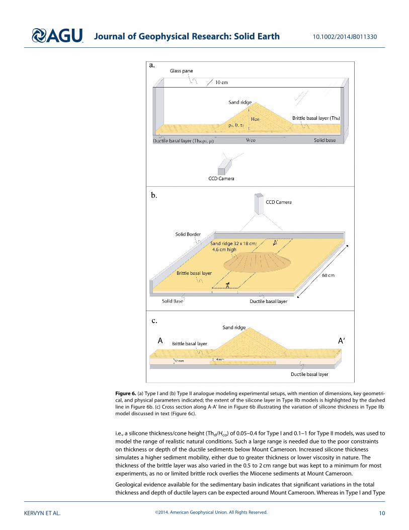
i.e., a silicone thickness/cone height (Thd/Hco) of 0.05–0.4 for Type I and 0.1–1 for Type II models, was used tomodel the range of realistic natural conditions. Such a large range is needed due to the poor constraintson thickness or depth of the ductile sediments below Mount Cameroon. Increased silicone thicknesssimulates a higher sediment mobility, either due to greater thickness or lower viscosity in nature. Thethickness of the brittle layer was also varied in the 0.5 to 2 cm range but was kept to a minimum for mostexperiments, as no or limited brittle rock overlies the Miocene sediments at Mount Cameroon.
Geological evidence available for the sedimentary basin indicates that significant variations in the totalthickness and depth of ductile layers can be expected around Mount Cameroon. Whereas in Type I and Type
Figure 6. (a) Type I and (b) Type II analogue modeling experimental setups, with mention of dimensions, key geometri-cal, and physical parameters indicated; the extent of the silicone layer in Type IIb models is highlighted by the dashedline in Figure 6b. (c) Cross section along A-A’ line in Figure 6b illustrating the variation of silicone thickness in Type IIbmodel discussed in text (Figure 6c).
Journal of Geophysical Research: Solid Earth 10.1002/2014JB011330
KERVYN ET AL. ©2014. American Geophysical Union. All Rights Reserved. 10

IIa models, the ductile substratum is homogenous across the entire model, a third set of models (Type IIb)investigates the influence of a ductile layer of spatially variable thickness upon edifice deformation. Slopedistribution and structural evidence at Mount Cameroon suggest that it is mostly the central part of thevolcanic ridge that is deforming (Figure 5). The ridge was therefore emplaced orthogonally upon a longsilicone band of limited width (i.e., 15 cm, half the ridge long axis, Figures 6b and 6c). The silicone layerwas bordered by sand in order to obtain a flat surface with limited brittle material (i.e., <5mm) over thesilicone. Variable silicone band thicknesses were tested from Thd/Hco = 0.1 to 0.5. Consistent with geologicalevidence, the thickness of the silicone was also varied along the silicone band. Type IIb experimentillustrated in results models the effect of an abrupt thickening of the silicone layer below the lower flanks,even though a more gradual, but so far unconstrained, transition may be expected in nature (Figure 6c).The ridge is built upon a 15 cm wide silicone band which is 0.4 cm thick below the central part of the ridge(Thd/Hco = 0.08) and 1.2 cm thick below the lower flank and flat brittle layer (Thd/Hco = 0.24).
Our experimental models focus exclusively on the effect of gravitational spreading on the deformation of avolcanic ridge. Deformation associated with magmatic intrusions or their influence on spreading structureswas investigated in a separate set of experiments [see Le Corvec and Walter, 2009] and will be considered inthe discussion of the results.
4.2. Scaling
In order to be comparable to natural volcanoes, analogue models need to be geometrically, kinematicallyand dynamically scaled. For scaling, we used the same approach developed in previous analogue modelingof volcano gravitational spreading [Merle and Borgia, 1996]. The different geometrical parameters are scaledwith a model/nature ratio of 10�5, i.e., 1 cm in analogue models represent 1 km in nature (Table 1).
The quartz sand used has an internal friction coefficient of 0.6, similar to natural brittle rocks. This ensures thatfault geometry in analogue models will be comparable to fault geometry in natural volcanoes [Schellart,2000]. The brittle material is generally assumed to nearly have a Mohr-Coulomb behavior [e.g., Ramberg,1981]. In addition, Lohrmann et al. [2003] showed that ~300μm quartz sand is characterized by strain-hardening and strain-softening effects similar to natural brittle rocks. The PDMS silicone has been used inmany similar studies and was shown to be a relevant analogue for ductile natural rocks [Schellart, 2000].
Dynamic scaling is achieved if the gravitational stress ratio σ* = ρ* × g* × h*, where ρ*, g* and h* are themodel/nature ratios for density, gravitational acceleration, and height of the volcano, respectively. Thiscalculation yields a stress ratio of ~5 × 10�6, indicating that the analogue volcano should be ~5 × 10⁶ timesmechanically weaker than a volcano in nature. Low cohesion granular material is here used to simulatevolcanoes with a bulk cohesion of up to 107 Pa, the approximate cohesion of fresh nonfractured rock. Theactual bulk cohesion of the volcano can be expected to be up to one order of magnitude lower as it is buildup by lava flows fractured from cooling or from postemplacement deformation [Hoek et al., 2002].
Kinematic scaling, i.e., the velocity at which the analogue model deforms relative to natural cases, is poorlyconstrained. Deformation velocities are entirely constrained by the balance between the brittle layer andvolcano load, through its density and height, on the one hand, and the viscosity of the underlyingmaterial onthe other [Delcamp et al., 2008]. Natural viscosity values of ductile sediments are ill constrained and range
Table 1. Material Properties and Model-to-Nature Ratios for Analogue Modeling Applied to Mount Cameroon
Symbol Parameters Dimension (Unit) Models Nature Model/Nature Ratio
Hco Ridge Height L (m) 4–11 × 10�2 4.1 × 10³ 1–2 × 10�5
Wco Ridge Width L (m) 2–4 × 10�1 2.5–5 × 10⁴ 1 × 10�5
Thd Ductile Layer Thickness L (m) 0.5–4 × 10�2 0.8–2 × 10³ 1–2 × 10�5
Thb Brittle Layer Thickness L (m) 0.5–2 × 10�2 0–5 × 10² 10�4–10�5
ρd Ductile Material Density M · L�3 (kg/m3) 970 2000–2500 0.38–0.48ρb Brittle Material Density M · L�3 (kg/m3) 1450 2500–2700 0.55–0.6μ Ductile Material Viscosity M · L�1 · T�1 (Pa s) 4 × 10⁴ 1016–1018 10–12–10–14
θ Coefficient of friction 0.6 0.6 1τ0 Cohesion M · L�1 · T�2 (Pa) <100 106–107 10–4–10�6
g Gravity L · T�2 (m s�2) 9.81 9.81 1t Time span of spreading T (s) 3 × 10³ 1012–1013 10�8–10�9
Journal of Geophysical Research: Solid Earth 10.1002/2014JB011330
KERVYN ET AL. ©2014. American Geophysical Union. All Rights Reserved. 11

over several orders of magnitude. As the sand material is assumed to have a near Mohr-Coulomb behavior,kinematic scaling has no major effect on the structural architecture, the fault types, and their geometry. Thus,although the deformation velocity of analogue models cannot be directly compared with natural cases, ourapproach allows investigation of the structures associated with the deformation, which are controlled by thesystem geometry rather than by deformation velocity [Delcamp et al., 2008; Le Corvec and Walter, 2009].Deformation of analogue models was documented for 1 h, whereas such processes are expected to takeplace over ~105 years in nature (Table 1). Assuming sediment viscosity of 1018 Pa s, 1 h of experimentsimulates deformation in nature over 104 to <105 years.
4.3. Digital Image Correlation Technique
Experiments were analyzed using a digital image correlation technique (DIC). We used a commercial softwarepackage, DAVIS, distributed by La Vision Company [LaVision, 2002]. The DIC technique was already used incomparable analogue models in previous studies [e.g., Adam et al., 2005; Burchardt and Walter, 2009; Le Corvecand Walter, 2009]. This technique is used to document strain localization with submillimeter spatial resolutionand detects displacements at the scale of individual sand grains [White et al., 2001]. For our experimentalsettings, spatial resolution of 0.34 and 0.25mm was achieved for the Type I and Type II setups, respectively.
A monochrome charge-coupled device digital camera was used to acquire images at high resolution (12megapixels). The camera was mounted on a rigid footing, and acquired images of the experiment surface at afixed interval of 2 s for 1 h. Then the stack of 15 successive images was computed to increase the signal to noiseratio. This provided one data set every 30 s, which proved sufficient to characterize the deformation structures.For each image correlation estimation, a multiple pass correlation algorithm over multiple-pixel grid cells(i.e., typically 16×16 pixels) enabled to unambiguously follow surface patterns through successive images.Analysis of sand grain displacements between successive image pairs led to documentation of surfacemovements and velocities orthogonal to the camera imaging axis, and to strain derivation, precise to ~0.1 pixels[White et al., 2001; Adam et al., 2005]. In our data we are thus able to detect 0.03mm deformation increments[LaVision, 2002; Adam et al., 2005].
Using standard postprocessing, several visual outputs can be produced from the DIC analysis, includingthe incremental velocity field and the displacement vector for each grid cell. From incrementaldisplacements in the X and Y directions, normal (Exx, Eyy) and shear strain (Exy, Eyx) rates can be derived[Adam et al., 2005]. Cumulative shear strain best documents structures that remain stationary throughout anygiven experiment.
5. Analogue Modeling Experiment Results5.1. Type I Models: Models Recorded in Cross Section
Figure 7 illustrates typical gravitational spreading as observed in the Type I experiments. As soon as the ridgeis emplaced onto the flat layers, a set of two listric normal faults are generated, each dipping at ~54° outward(Figure 7). These faults accommodate outward movement of the ridge flanks, as underlying silicone flowslaterally under the ridge load. For Thd/Hco ~ 0.25 (Figure 7), the two listric faults intersect each other below thesummit, defining a summit graben. With a thinner silicone layer (Thd/Hco ~0.18), the listric faults intersect atthe ridge summit (Figure S1 in the supporting information). As the Thd/Hco is further reduced, the listricnormal fault traces are observed on the flanks leaving the summit region undeformed.
Figure 7 illustrates that, for a thick silicone layer (Thd/Hco ~0.25), a second set of shallow listric normal faultsforms and accommodates horizontal outward displacement of lower flanks and flank slumping. Antitheticnormal inward dipping faults are associated with this shallow fault system. They cause a discontinuity in thevelocity field between a rapidly subsiding wedge at midflank and laterally moving lower flanks (Figure 7b).Upper andmidflanks are dominated by outward rotation of entire blocks of the edifice, resulting in tilting of thesurface with greater subsidence closer to the normal fault traces. Highest displacement velocities are recordedalong the shallow normal faults and within a summit graben. For a thin silicone layer (Thd/Hco<0.20), the deepoutward dipping normal faults are directly associated with antithetic normal faults dipping at 60° and cuttinginto the midflank, forming a concave slope break at the surface (Figure S1). This pattern is similar to thatobserved by Le Corvec and Walter [2009] for spreading of half ridges over a thin silicone layer.
Journal of Geophysical Research: Solid Earth 10.1002/2014JB011330
KERVYN ET AL. ©2014. American Geophysical Union. All Rights Reserved. 12

During the experiments, the silicone flows laterally, thins beneath the ridge and thickens and bulges up at theridge base. Above the bulged silicone, the brittle material is folded. This deformation is at maximum nearthe ridge base but folding extends, with lower amplitude, to the model edge, 30 cm away from ridge base,after 60min of deformation.
5.2. Type IIa Models: Uniform Models Imaged From Above
Figure 8 presents the results of a typical Type IIa experiment with a homogeneous silicone layer ofuniform thickness. The initial deformation is characterized by radial deformation of the entire ridge withhigher outward horizontal velocities perpendicular to the elongation axis (Figure 8b). The summit zoneis not affected by horizontal displacement but subsides vertically, forming a central elongated graben.The width of this graben and the accumulated strain decreases toward the base of the elongatedridge. Cumulative volumetric strain after 20min shows that deformation is mostly accommodated bythe two arcuate structures bounding the summit graben with limited internal deformation withinthe flanks (Figure 8c). In all experiments, the faults bounding the central graben intersect at the baseof the ridge.
As the model continues to deform, triangular wedges, separated by subvertical faults, are observed on theshear strain accumulation map (Figure 8c). The triangular wedges pointing toward the ridge summitmove radially outward at a faster rate than the ones pointing toward the base of the ridge (Figure 8b). Thelatter displays evidence of vertical subsidence. These graben structures affect the entire long flanks butthe ones closest to the middle of the ridge concentrate most of the strain. Flank slopes systematicallydecrease as deformation proceeds, never leading to flank instabilities.
The width of the central graben increases with time. The initial graben-bounding faults are displaced laterallyas they bound the outward moving flanks. Two new conjugate faults form at a later stage within the existinggraben at the initial location of the first set of faults. Significant shear strain is recorded along the graben-bounding faults indicating that these are transtensional structures rather than pure extensionalones (Figure 8c).
Beyond the ridge foot, the velocity of horizontal movements reduces radially outward (Figure 8b). Thisindicates the accumulation of significant, dominantly compressive, strain around the ridge base. This isassociated with the subconcentric anticlines and thrusts observed in the brittle substratum near the ridgebase. Cumulative strain and vertical fold amplitude are greatest at the base of the long flanks of the ridge.Deformation extends in the flat surface to a maximum distance of half the short radius of the ridge.
To evaluate the influence of relative thickness for the brittle and ductile layers upon the observed structures,a series of 23 experiments are conducted with systematic variations of the geometric ratios Thb/Thd, Thb/Hco,and Thd/Hco. Results show that a thick brittle layer (1< Thb/Thd<3) is associated with deformation limited tothe formation of the central graben or no deformation at all (Thb/Thd >3; see Figure S2). Irrespective ofductile layer thickness, a thick brittle crust relative to ridge height (Thb/Hco) also limits or prevents any
Figure 7. Lateral view of a Type I experiment with 3 cm silicone after (left column) 30min and (right column) 60min ofdeformation. (a) Raw image for the experiment; (b) cumulative displacement vector field indicating displacement direc-tion and amplitude since deformation onset; and (c) cumulative shear strain with right lateral (blue) and left lateral (red)shear strain concentration showing two sets of normal listric faults. Two complementary normal faults cross below apex,delimiting a summit graben. Shallower outward dipping normal faults affect flanks and form steep unstable upper flanks.See Figure 10a for interpretation.
Journal of Geophysical Research: Solid Earth 10.1002/2014JB011330
KERVYN ET AL. ©2014. American Geophysical Union. All Rights Reserved. 13

gravitational deformation. A very thick ductile layer (Thb/Thd <0.1) induces vertical sagging of the ridge intothe ductile basement, causing compressive stresses along the flank and extensional fractures around its base[see Kervyn et al., 2010; Byrne et al., 2013].
5.3. Type IIb Model: Ductile Layer of Nonuniform Thickness
Figure 9 illustrates the deformation of Type IIb models in which a narrow silicone band is placed orthogonalto the ridge axis with a lower thickness below the ridge than under the lower flanks and flat base (Figures 6band 6c). The deformation is restricted to the segment of the ridge built over the silicone layer and iscontrolled by two sets of symmetric listric faults formed simultaneously. The deepest faults border a narrowsummit graben. The second set of faults accommodates the faster outward movements of the lowerflanks associated with the formation of unstable upper flanks (Figure 9). The shallow faults’ position iscontrolled by the position of the step in silicone thickness. Both sets of faults have a dominant normalcomponent in their central part and turn into strike-slip structures at the lateral edge of the deforming flanks
Figure 8. Plan view of a Type IIa spreading sand ridge. Silicone and sand layers are each 0.5 cm thick. Elongated ridge is18 × 32 cm and 4.6 cm high. (a) Image of model after 20min (left column) and 40min (right column) of deformation; (b)cumulative displacement vector field indicating displacement direction and amplitude since deformation onset; and (c)cumulative shear strain with right lateral (blue) and left lateral (red) shear strain concentration highlighting strike-slip faultsbordering the main central graben and smaller V-shaped grabens on the flanks. See Figure 10b for interpretation.
Journal of Geophysical Research: Solid Earth 10.1002/2014JB011330
KERVYN ET AL. ©2014. American Geophysical Union. All Rights Reserved. 14

(Figure 9). The shallow faults have subcircular surface traces, whereas a sharper transition in structureorientations is recorded for the deeper faults (Figure 10c).
The extent of the summit graben is bounded by the intersection of the two deep normal faults with oppositedip orientation. The long axis of the summit graben matches with the lateral extent of the deformingflanks. As flanks are constantly moving outward, whereas strain localization is observed to be stationary,several faults form successively, creating several topographic steps at the edges of the summit graben(Figures 9 and 10c).
Sharp topographic steps at intermediate height within the deforming flanks are identified at the experimentonset. These suggest the presence of inward dipping antithetic faults associated with the deeper faults whenmovement is faster along the deeper graben-bounding faults. As deformation progresses strain concentrateson the flanks, with less deformation along graben-bounding faults (Figure 9). Antithetic faults are no longeractive but remain as topographic steps in the lower flanks.
Figure 9. Plan view of a Type IIb experiment with nonuniform silicone layer. A 15 cm band of silicone is emplaced perpen-dicular to the ridge axis (white rectangle in Figure 9a), below its central part. Silicone is 4 and 12mm thick below the ridgecentral part and lower flank and base, respectively. (a) Image of model after 20min (left column) and 40min (right column)of deformation; (b) cumulative displacement vector field indicating displacement direction and amplitude since defor-mation onset; and (c) cumulative shear strain with right lateral (blue) and left lateral (red) shear strain concentration alongstrike-slip faults. See Figure 10c for interpretation.
Journal of Geophysical Research: Solid Earth 10.1002/2014JB011330
KERVYN ET AL. ©2014. American Geophysical Union. All Rights Reserved. 15

Destabilization of the flanks by shallow slumps is observed when the lower flanks are spreading outward,along the shallow faults, faster than the upper flanks, along the deeper faults. Such dynamics is only obtainedwhen the silicone layer is thinner below the ridge than below the lower flanks and flat substratum. When thesilicone thickness is homogeneous, the deformation along the deeper faults is faster and do not result in theformation of unstable flanks.
Shear strain localization along linear structures striking downslope points to the formation of strike-slip faultsrelaying the summit graben edges to the deforming lobes at the base of the ridge (Figures 9 and 10). Materialfolding and thrusting within the flat base occur in the direction perpendicular to the ridge’s elongationaxis and extend to greater distances from the base than observed in Type IIa experiments. Folds and thrustshave a parabolic outline with significant strain accumulation in the brittle layer at the lateral edge of thesilicone band (Figure 9): these lateral edges are marked by topographic steps caused by uplift of thedeforming zone relative the stable substratum.
Relative position and interactions of the shallow fault on one flank and the deep listric fault dipping in theopposite direction are responsible for complex topographic irregularities along the summit zone. The initialposition of the different fault structures depends on the thickness distribution and the width of the siliconelayer accommodating the deformation.
6. Discussion6.1. Morphostructural Interpretation
The faults and folds obtained in analoguemodels, as well as themorphology of the deformed ridges, are herecompared with the structural map and surface morphology of Mount Cameroon (Figures 5 and 10).
For the models in cross section (Type I, Figure 10a), lateral flank spreading results in an uneven flank slopedistribution with steep slopes being formed at midflanks by the shallow listric normal faults and flatter terrainson the lower flanks associated to antithetic faults. Toward the summit, a flat graben is formed by intersection of
Figure 10. Interpretation sketches for the analogue models presented in Figures 7–9. (a) Type I model: spreading of a sandridge between glass panes over 3 cm of silicone as presented in Figure 7. (b) Type IIa model: spreading sand ridge presentedin Figure 8; and (c) Type IIb model: spreading of a sand ridge over a nonuniform ductile layer as presented in Figure 9; SG:summit graben; SS: strike-slip fault; SLF: shallow listric fault; and AF: antithetic fault. Orange color: steep unstable slopes.
Journal of Geophysical Research: Solid Earth 10.1002/2014JB011330
KERVYN ET AL. ©2014. American Geophysical Union. All Rights Reserved. 16

the two main listric normal faults. The resulting edifice profile for such a faulting configuration is very similar tothat observed at Mount Cameroon, with a flat summit zone bounded by normal faults, steep upper flanks, andlow angle lower flanks turning into a far-reaching folded basal zone (Table 2 and Figure 10a).
In experiments recorded from above with a homogeneous ductile layer (Type IIa and Figure 10b),gravitational stresses cause radially outward flow of the silicone initially located below the ridge. This inducesa radial spreading of the ridge and the formation of V-shaped grabens on the ridge flanks. These features aresimilar to grabens observed in experiments simulating the spreading of axisymmetric cones [Merle andBorgia, 1996; Delcamp et al., 2008; Kervyn et al., 2010]. The gravitational stress gradient is larger orthogonal tothe long axis of the ridge. The lateral spreading thus occurs at a faster rate in that direction, leading to a betterdeveloped summit graben and more extensive basal deformation orthogonal to the long axis. Radialdissipation of the compressive strain away from the ridge’s base limits the extent of the thrusts and foldsaffecting the flat surface. The extent of the summit graben, the occurrence of spreading-related grabens onthe long flanks, and the absence of steep slopes do not match with the observed morphology of MountCameroon (Table 2).
In the third set of experiments with a nonhomongeneous ductile layer (Type IIb, Figure 10c), the spreading islaterally constrained by the extent of the ductile layer. This results in the unidirectional spreading of the longflanks in a direction orthogonal to the ridge’s long axis. The shear stress at the edge of the spreading flankscauses the listric normal faults to turn downslope into strike-slip faults, separating the deformation of thespreading flanks from the stable part of the ridge. The deep listric normal faults border a narrow summitgraben which length is limited to that of the spreading flanks. Faster outward spreading of the lower flanks, dueto variation in ductile layer thickness, leads to the formation of additional outward dipping listric normal faultswhich are associated with the formation of steep and unstable slopes on the upper flanks. Deformation beyondthe base of the ridge extends to a great distance but is limited to a parabolic-shaped area adjacent to thespreading flanks. This Type IIb model best reproduces the features observed at Mount Cameroon (Table 2).Therefore, we deduce that the deformation dynamics and velocity fields documented for this type of analoguemodel (Figures 9 and 10) best represent the long-term dynamics of gravitational deformation atMount Cameroon.
6.2. Mount Cameroon—A Spreading Volcano
From interpretation of topographic and volcano-tectonic structures and from comparison with analoguemodels, we propose an interpretative model in which Mount Cameroon deforms over ductile sediments(Figure 11c). The structure of the sedimentary basins, with the stepwise sediment thickening toward SSW andincreased occurrence of clay-rich layers in the Tertiary sediments, is interpreted as responsible for restrictionof spreading to the central part of Mount Cameroon. Only in that zone is the load sufficient and the ductilelayer present at a favorable depth to cause outward ductile sediment flow and associated flank spreading.The sharp lateral limit for basal deformation NW of the volcano, along a N125°E linear feature, is consistentwith this interpretation: the different parts of the sedimentary basins are separated by N120–135°E normalfaults dipping SW [e.g., Regnoult, 1986; Moreau et al., 1987].
Table 2. Comparison of Morphostructural Features Observed at Mount Cameroon and Those Reproduced by the Three Sets of Analogue Modelsa
Morphostructural Features of Mount Cameroon Type I Type IIa Type IIbRift Zone Intrusion
[Le Corvec and Walter, 2009]b
Steep unstable long flanks V X V (V)Linear SE flank (V) X V (V)Convex NW flank + Elephant Valley X X X XSharp break-in-slope at base of steep flanks V X V (V)Fault bounded elliptical summit plateau (V) X V (V)Undeformed lower flanks along rift zone X X V (V)Parabolic sediment ridges subparallel to volcano long flanks (V) V V XStrike-slip faults orthogonal to elongation axis X (V) V X
aSee text for discussion. V, feature reproduced by experiment; (V), feature partially reproduced or consistent if Type I models are extrapolated in 3-D; and X,feature not reproduced.
bThe deformation caused by rift zone intrusion is evaluated from experiments illustrated in Le Corvec and Walter [2009]: locally unstable flanks are formed onlyfor shallow intrusions whereas basal thrusts and folds are associated with deep intrusion and do not extend beyond the cone base.
Journal of Geophysical Research: Solid Earth 10.1002/2014JB011330
KERVYN ET AL. ©2014. American Geophysical Union. All Rights Reserved. 17

Analogue models suggest that a summit graben and steep upper flanks can only coexist at MountCameroon if there are differential outward spreading velocities between lower flanks and summit area.Such differential spreading can arise when the depth or thickness of ductile sediments varies across thevolcanic axis or if a buttress exists in the underground, hindering spreading in one or some directions[Walter, 2003]. Such an interpretation is consistent with offshore observations of uplifted Miocene crust byMeyers et al. [1998]. Assuming that such crustal uplift also affected Mount Cameroon basement in theMiocene, the lower thickness of ductile material below the volcano central zone causes slow movementalong the deep normal faults accommodating summit subsidence, and more rapid movement of the outerflank, which overlies thicker sediments. The striking slope breaks observed at the base of the steep upperflanks are also interpreted here as the topographic expression of antithetic faults associated with shallowlistric normal faults (Figure 2). Repetitive dyke intrusions along the rift zone are expected to contribute tooversteepening of the upper flanks when emplaced at shallow depth and may contribute to the subsidence ofthe summit graben.
There is a noticeable absence of structures or other evidence of deformation affecting the NE and SW flanksof Mount Cameroon. NE of the spreading sector, the underlying sediments are mostly composed of lessreadily deformable Cretaceous siltstones and sandstones. The limited extent of the NE volcanic rift zone isconsistent with the absence of extensional strain to the NE. To the SW, the presence of the older Limbe-
Figure 11. Conceptual sketches of two end-member deformation structures induced by (a) gravitational spreading, basedon experimental results presented in this paper, and (b) volcanic rift zone intrusions modeled by Le Corvec and Walter[2009]. (c) Interpretation of Mount Cameroon cross-section orthogonal to the elongation axis shown in Figure 2c illustratingthe position of, and movement along faults as interpreted from analogue modeling (adapted from Mathieu et al. [2011]).Vertical scale is exaggerated 3 times for better clarity.
Journal of Geophysical Research: Solid Earth 10.1002/2014JB011330
KERVYN ET AL. ©2014. American Geophysical Union. All Rights Reserved. 18

Mabeta volcanic massif and of Mount Etinde volcano can potentially act as local buttressing, limiting thepotential deformation of the volcano in that area. The flank may not be wide enough to overlay the thickersediment. The broad extent of the eruptive fissures to low elevations, however, suggests that extensionalstrain is greater on the SW flank relative to the NE flank. Finally, the overall absence of V-shaped grabensperpendicular to the elongation axis—with the noticeable exception of the Elephant Valley—suggests thatno or limited spreading is taking place parallel to the volcano long axis, due to presence of the stable SE andNW flanks of Mount Cameroon.
6.3. Limitations of the Analogue Models
A thorough comparison of the analogue models with Mount Cameroon architecture is prevented by the lackof geophysical data. Existing seismic evidence is however consistent with the proposed model [Ambeh et al.,1989; Ateba and Ntepe, 1997; Ubangoh et al., 1997]. Most earthquakes recorded in the 1980s were singleevents or swarms below the two spreading sectors. To the NW, earthquakes occurred at less than 10 kmdepth [Ambeh et al., 1989]. Interestingly, seismic swarms below the spreading flanks are more commonduring the rainy season [Ubangoh et al., 1998]. Although the accuracy of hypocenter localization is insufficientto draw definitive conclusions, such earthquake swarms are consistent with movement of the unstable flanksalong one or several decollement surfaces within the sedimentary deposits. Existing field evidence at MountCameroon presented by Mathieu et al. [2011] is also consistent with the model proposed here.
Table 2 highlights that the only topographic feature of Mount Cameroon that is not properly accounted for byour conceptual model (Figure 11) and not reproduced by our analogue experiments is the presence of theElephant Valley and its surrounding outward topographic bulge within the steep NE flank. Our model doesnot confirm, or invalidate, previously proposed explanations for the formation of this valley: e.g., glacialerosion [Déruelle et al., 1987], radial spreading [Suh et al., 2003], or extensional stresses associated with therotation of a large block within the flank [Mathieu et al., 2011]. The fresh nature and steep slopes of theElephant Valley wall suggest that it is a recent or still-active morphological structure. We hypothesize that aninterplay of differential outward spreading velocities within the flank, a tectonic discontinuity orthogonal toMount Cameroon elongation, and cutting across the volcano, and/or an asymmetry in magmatic forcingmight have contributed to create the local topographic bulge within the NE flank. Such deformation couldthen have triggered flank destabilization, local extensional stresses, or concentrated erosion to carve theElephant Valley itself. Further geophysical and structural investigations in the field are required to unravel theorigin of this valley.
Our model does not take into account the potential effect of regional tectonics upon the deformation atMount Cameroon. This is made difficult by the lack of constraints on the activity and dynamics ofdocumented tectonic structures in the region, the main ones being oriented N030°E, N050°E to N070°E, andN000°E and N130°E [Moreau et al., 1987]. Other processes are also neglected in our models: (i) heterogeneousrock properties within the sediment substrata or within the volcano, e.g., presence of a shallow magmareservoir or a dyke core complex below the central rift zone, (ii) possible non-Newtonian rheology of theductile layer, and (iii) gradual—instead of instantaneous—growth of the volcano load.
Moreover, the analogue models focus on gravitational deformation (Figure 11a) and do not reproduce thecontribution of magma intrusions to Mount Cameroon deformation and structure. Magma storage into ashallow reservoir (i.e.,<5 km depth) and repetitive subvertical dyke emplacement within the main rift zone isexpected to be associated with significant volcano deformation. Le Corvec and Walter [2009] showed thatsuch rift zone intrusions is associated with graben formation above the dyke complex and outward flankdisplacement along a subhorizontal fault at the level of the intrusion base (Figure 11b and Table 2). Thisoutward movement of a coherent flank leads to localized flank steepening and shallow instability forintrusions initiated at shallow depth, or to thrusting of the flank base if the deformation was accommodatedby a deep decollement (Figure 11b), but both features were not reproduced simultaneously. Combinedgravitational spreading and intrusion was also shown to be sometimes associated with subdued expressionof the spreading-related listric faults.
It is expected that repetitive dyke injection along the central rift zone of Mount Cameroon plays an importantrole in its structure and deformation. Formation of a dyke complex might have contributed to the formationof a central graben although its limited longitudinal extent relative to the distribution of eruptive vents
Journal of Geophysical Research: Solid Earth 10.1002/2014JB011330
KERVYN ET AL. ©2014. American Geophysical Union. All Rights Reserved. 19

suggests that intrusion-induced deformation cannot account for it alone. Dyke intrusions at shallow levelmight also have contributed to oversteepening and destabilization of upper flanks, although there is noevidence for a shallow source of intrusion within Mount Cameroon [Suh et al., 2003]. Unraveling the relativeimportance of intrusion-induced destabilization relative to that caused by gravitational deformation atMount Cameroon remains a challenge as the frequency of intrusions and the velocity of flank spreadingbetween intrusive events is not yet constrained. However, the limited extent of the summit graben and thestriking correspondence between fault locations and types with gravitationally induced structures inanalogue models suggests that Mount Cameroon is spreading under gravity faster than it is being pushed byforceful intrusions.
6.4. Analogue for Flank Slumps at Other Volcanoes
All of Mount Cameroon’s deformation-related structures are visible on land. Many other large volcanicconstructs are either oceanic islands (e.g., Hawaii, Piton de la Fournaise) or built on the shoreline (e.g., Etna).Deformation structures affecting the lower flanks at these other volcanoes are thus more difficult to map.Several of these volcanoes show strong evidence for continuous, usually asymmetric, flank spreading driven bygravity and/or repeated magmatic intrusions [see Le Corvec and Walter, 2009], sometimes in interaction withtectonic faulting (e.g., Etna) [Le Corvec et al., 2014]. Processes documented here—i.e., laterally constrained flankspreading, associated with summit subsidence, and shallow slumps affecting upper slopes due to differentialspreading velocity of the lower flanks—are expected to similarly apply to some of these structures whereboth summit subsidence and flank slumping (e.g., Hilina Pali faults, Kilauea) [Morgan et al., 2003] or sectorcollapses are observed simultaneously [Oehler et al., 2005]. Similar processes are also expected to occur atextraterrestrial volcanoes: e.g., Platz et al. [2011] inferred a variation in substratum rheology to account for theunidirectional flank spreading of Tharsis Tholus on Mars, resulting in a comparable morphology as that ofMount Cameroon. The exact dynamics of the process and source of the differential movement for lower flank ishowever expected to vary with the local setting.
7. Conclusions
Analogue models presented here provide insights into the complex deformation structures documented atMount Cameroon from morphostructural analysis of the SRTM digital elevation model and from fieldevidence [Mathieu et al., 2011]. Directional spreading of the central part of the volcano over the underlyingsedimentary basins is proposed to be largely responsible for the observed structures, although repetitivedyke intrusions along the rift zone certainly contribute to the overall deformation pattern and structures.Variations of the sediment thickness and properties across the Cameroon Volcanic Line, associated withcrustal uplift, can account for differential movement of the lower flanks, creating simultaneously a flat summitgraben, unstable upper slopes, and far reaching basal folds and faults.
This deformation model for Mount Cameroon has implications for nonmagmatic earthquakes and slopeinstability hazards (see Bonne et al. [2008] and Thierry et al. [2008] for further discussion of hazards at MountCameroon). Repeated slope instabilities are likely to affect the steep upper flanks, and to potentially affectdensely inhabited areas (e.g., Buea). Seismic activity associated with flank spreading along the strike-slipfaults (e.g., Bokosso faults) or underneath the spreading flanks is also likely to pose a seismic hazard outsideeruptive periods [see Ubangoh et al., 1997]. The presented analogue models also provide insights for othervolcanoes where large-scale flank spreading and summit subsidence are associated with localizedflank instabilities.
Mount Cameroon has been increasingly studied since the 1999 and 2000 eruptions, and there is now anopportunity to start characterizing its deformation dynamics and magmatic system systematically. Furtherstudies are needed to quantify the rate of movement of the well-expressed faults bordering the summitplateau and the Bokosso faults, to unravel effects of magma intrusion and the origin of the Elephant Valley.This can be achieved by applying ground-based (broadband seismometer array, GPS, and gravimetry) andspaced-based geophysical methods (synthetic aperture radar interferometry) during and in-betweeneruptive periods. Specific field studies to document the Elephant Valley floor and wall deposits systematicallywould be beneficial. Such studies at Mount Cameroon would be well suited and timely to help advance theunderstanding of large basaltic volcanoes, and would also contribute to quantifying hazards and risks at thisdensely populated volcano.
Journal of Geophysical Research: Solid Earth 10.1002/2014JB011330
KERVYN ET AL. ©2014. American Geophysical Union. All Rights Reserved. 20

ReferencesAdam, J., J. Urai, B. Wienecke, O. Oncken, K. Pfeiffer, N. Kukowski, J. Lohrmann, S. Hoth, W. Van Der Zee, and J. Schmatz (2005), Shear
localization and strain distribution during tectonic faulting—New insights from granular-flow experiments and high resolution opticalimage correlation techniques, J. Struct. Geol., 27, 283–301.
Ambeh, W. B., J. D. Fairhead, D. J. Francis, J. M. Nnange, and D. Soba (1989), Seismicity of the Mount Cameroon region, West Africa, J. Afr. EarthSci., 9, 1–7.
Ateba, B., and N. Ntepe (1997), Post-eruptive seismic activity of Mount Cameroon (Cameroon), West Africa: A statistical analysis, J. Volcanol.Geotherm. Res., 79, 25–45.
Ateba, B., C. Dorbath, L. Dorbath, N. Ntepe, M. Frogneux, F. T. Aka, J. V. Hell, J. C. Delmond, and D. Manguelle (2009), Eruptive and earthquakeactivities related to the 2000 eruption of Mount Cameroon volcano (West Africa), J. Volcanol. Geotherm. Res., 179, 206–216.
Belmonte, Y. C. (1966), Stratigraphie du bassin sédimentaire du Cameroun, paper presented at Second West African MicropaleontologicalColloquium, Ibadan.
Benkhelil, J., P. Giresse, C. Poumot, and G. Ngueutchoua (2002), Lithostratigraphic, geophysical and morpho-tectonic studies of the SouthCameroon shelf, Mar. Pet. Geol., 19(4), 499–517.
Bonne, K., M. Kervyn, L. Cascone, S. Njome, E. Van Ranst, E. Suh, S. Ayonghe, P. Jacobs, and G. G. J. Ernst (2008), A new approach to assess long-termlava flow hazard and risk using GIS and low cost remote sensing: The case of Mount Cameroon, West Africa, Int. J. Remote Sens., 29, 6539–3564.
Borgia, A., L. Ferrari, and G. Pasquarè (1992), Importance of gravitational spreading in the tectonic and volcanic evolution of Mount Etna,Nature, 357(6375), 231–235.
Borgia, A., P. T. Delaney, and R. P. Denlinger (2000), Spreading volcanoes, Annu. Rev. Earth Pl. Sc., 28, 539–570.Brownfield, M. E., and R. R. Charpentier (2006), Total petroleum systems, West-Central coastal Province, West Africa, USGS Geol. Surv. Bull.,
2207-B, 1–52.Burchardt, S., and T. R. Walter (2009), Propagation, linkage, and interaction of caldera ring-faults: Comparison between analogue experi-
ments and caldera collapse at Miyakejima, Japan, in 2000, Bull. Volcanol., doi:10.1007/s00445-00009-00321-00447.Byrne, P. K., E. P. Holohan, M. Kervyn, B. V. de Vries, V. R. Troll, and J. B. Murray (2013), A sagging-spreading continuum of large volcano
structure, Geology, 41(3), 339–342.Byrne, P. K., E. P. Holohan, M. Kervyn, B. van Wyk de Vries, and V. R. Troll (2014), Analogue modelling of volcano flank terrace formation on
Mars, Geol. Soc. London Spec. Publ., doi:10.1144/SP1401.1114.Chiarelli, A. (1976), Étude des nappes aquiferes profondes du bassin de Douala, Cameroun. Study of the deep aquifers of Douala Basin,
Cameroon, in Hydrogeology of Great Sedimentary Basin, Proceeding of the International Hydrogeological Conference, Budapest, Hungary,edited by R. Andras et al., p. 322, Budapest.
Delaney, P. T. (1992), Volcanoes—You can pile it only so high, Nature, 357(6375), 194–196.Delcamp, A., B. V. de Vries, and M. R. James (2008), The influence of edifice slope and substrata on volcano spreading, J. Volcanol. Geotherm.
Res., 177(4), 925–943.Déruelle, B., J. Nni, and R. Kambou (1987), Mount Cameroon—An active volcano of the Cameroon Line, J. Afr. Earth Sci., 6(2), 197–214.Déruelle, B., I. Ngounouno, and D. Demaiffe (2007), The “Cameroon hot line”: A unique example of active alkaline intraplate structure in both
oceanic and continental lithosphere, C. R. Geosci., 339, 589–600.Dieterich, J. H. (1988), Growth and persistence of Hawaiian volcanic rift zones, J. Geophys. Res., 93(B5), 4258–4270, doi:10.1029/
JB093iB05p04258.Dumort, J. C. (1968), Notice Explicative de la Feuille Douala Ouest avec carte gélogique au 1/500 000, Dir. Mines Géol, Cameroon.Dzurisin, D. (2007), Volcano Deformation: Geodetic Monitoring Techniques, 441 pp., Springer, Berlin.Fiske, R. S., and E. D. Jackson (1972), Orientation and growth of Hawaiian volcanic rifts: The effect of regional structure and gravitational
stresses, Proc. Roy. Soc. Lond. A, 329, 299–326.Fitton, J. G., C. R. J. Kilburn, M. F. Thirlwall, and D. J. Hughes (1983), 1982 Eruption of Mount Cameroon, West-Africa, Nature, 306(5941), 327–332.Gallacher, R. J., and I. D. Bastow (2012), The development of magmatism along the Cameroon Volcanic Line: Evidence from teleseismic
receiver functions, Tectonics, 31, doi:10.1029/2011TC003028.Gèze, B. (1943), Géographie physique et géologie du Cameroun occidental, Mémoire du Muséum National d’Histoire, 17, 1–272.Grosse, P., B. V. de Vries, I. A. Petrinovic, P. A. Euillades, and G. E. Alvarado (2009), Morphometry and evolution of arc volcanoes, Geology, 37(7),
651–654.Hedberg, J. D. (1968), A geological analysis of the Cameroon trend, PhD thesis, 154 pp., Princeton Univ., Princeton.Hoek, E., C. Carranza-Torres, and B. Corkum (2002), Hoek-Brown failure criterion—2002 Edition, paper presented at Proceeding North
American Rock Mechanics Society - TAC Conference, Toronto.Kervyn, M., M. Boone, B. van Wyk de Vries, E. Lebas, V. Cnudde, K. Fontijn, and P. Jacobs (2010), 3D imaging of volcano gravitational defor-
mation by computerized X-ray micro-tomography, Geosphere, 6(5), 482–498, doi:10.1130/GES00564.1.LaVision (2002), StrainMaster Manual for DaVis 6.2, LaVision GmbH, Goettingen.Le Corvec, N., and T. R. Walter (2009), Volcano spreading and fault interaction influenced by rift zone intrusions: Insights from analogue
experiments analyzed with digital image correlation technique, J. Volcanol. Geotherm. Res., 183(3–4), 170–182, doi:10.1016/j.jvolgeores.2009.02.006.
Le Corvec, N., T. R. Walter, J. Ruch, A. Bonforte, and G. Puglisi (2014), Experimental study of the interplay between magmatic rift intrusion andflank instability with application to the 2001 Mount Etna eruption, J. Geophys. Res. Solid Earth, 119, 5356–5368, doi:10.1002/2014JB011224.
Le Maréchal, A. (1975), Carte géologique de l’Ouest du Cameroun et de l’Adamaoua, 1:1000000, ORSTOM, Office de la Recherche Scientifiqueet Technique d’Outre-mer, Bondy, France.
Lohrmann, J., N. Kukowski, J. Adam, and O. Oncken (2003), The impact of analogue material properties on the geometry, kinematics anddynamics of convergent sand wedges, J. Struct. Geol., 25, 1691–1711.
Marzoli, A., E. M. Piccirillo, P. R. Renne, G. Bellieni, M. Iacumin, J. B. Nyobe, and A. T. Tongwa (2000), The Cameroon line revisited: Petrogenesisof continental basaltic magmas from lithospheric and asthenospheric mantle sources, J. Petrol., 41, 87–109.
Mathieu, L., and B. van Wyk de Vries (2009), Edifice and substrata deformation induced by intrusive complexes and gravitational loading inthe Mull volcano (Scotland), Bull. Volcanol., 71(10), 1133–1148.
Mathieu, L., M. Kervyn, and G. G. J. Ernst (2011), Field evidence for flank instability, basal spreading and volcano-tectonic interactions at MtCameroon, West Africa, Bull. Volcanol., 73(7), 851–867, doi:10.1007/s00445-00011-00458-z.
McGovern, P. J., and J. K. Morgan (2009), Volcanic spreading and lateral variations in the structure of Olympus Mons, Mars, Geology, 37(2),139–142.
Journal of Geophysical Research: Solid Earth 10.1002/2014JB011330
KERVYN ET AL. ©2014. American Geophysical Union. All Rights Reserved. 21
Acknowledgments
Data from analogue models presentedin this manuscript are available uponrequest to M.K. Comments on a preli-minary version of this manuscript byL. Mathieu and A. Delcamp, and reviewsby A. Tibaldi, N. Le Corvec, and A. Borgiagreatly helped to improve this article.M.K. and G.G.J.E. partly conducted thisresearch during their postdoctoral atGhent University with the support ofthe Fonds voor WetenschappelijkOnderzoek—Vlaanderen. Experimentalresults were obtained during researchstays of M.K. at LMV and GFZ, thanks tofinancial support by FWO and BlaisePascal University. We are grateful toOnno Oncken for granting access to theGFZ analogue lab. We acknowledgetechnical assistance and stimulatingdiscussions with many researchers andstudents in those labs, especially LucieMathieu, Matthias Roseneau, and DavidBoutelier. This research was conductedin the framework of the VLIR OwnInitiative project entitled Capacitybuilding in geohazards monitoring involcanically active areas of SW Cameroonbetween UGhent and UBuea. We finallyacknowledge collaboration and supportof staff and students at the DGES ofUBuea during fieldwork.

Merle, O., and A. Borgia (1996), Scaled experiments of volcanic spreading, J. Geophys. Res., 101(B6), 13,805–13,817, doi:10.1029/95JB03736.Meyers, J. B., and B. R. Rosendahl (1991), Seismic-reflection character of the Cameroon Volcanic Line—Evidence for uplifted oceanic-crust,
Geology, 19(11), 1072–1076.Meyers, J. B., B. R. Rosendahl, H. Groschel-Becker, J. Austin, and P. A. Rona (1996), Deep penetrating MCS imaging of the rift-to-drift transition,
offshore Douala and North Gabon basins, West Africa, Mar. Pet. Geol., 13(7), 791–835.Meyers, J. B., B. R. Rosendahl, C. G. A. Harrison, and Z. D. Ding (1998), Deep-imaging seismic and gravity results from the offshore Cameroon
volcanic line, and speculation of African hotlines, Tectonophysics, 284(1–2), 31–63.Milelli, L., L. Fourel, and C. Jaupart (2012), A lithospheric instability origin for the Cameroon Volcanic Line, Earth Planet. Sci. Lett., 335, 80–87.Moreau, C., J. M. Regnoult, B. Deruelle, and B. Robineau (1987), A new tectonic model for the Cameroon Line, Central-Africa, Tectonophysics,
141(4), 317–334.Morgan, J. K., G. F. Moore, and D. A. Clague (2003), Slope failure and volcanic spreading along the submarine south flank of Kilauea volcano,
Hawaii, J. Geophys. Res., 108(B9), 2415, doi:10.1029/2003JB002411.Njome, M. S., C. E. Suh, R. S. J. Sparks, S. N. Ayonghe, and J. G. Fitton (2008), The Mount Cameroon 1959 compound lava flow field:
Morphology, petrography, geochemistry, Swiss J. Geosci., 101, 85–98.Oehler, J. F., B. V. de Vries, and P. Labazuy (2005), Landslides and spreading of oceanic hot-spot and arc shield volcanoes on Low Strength
Layers (LSLs): An analogue modeling approach, J. Volcanol. Geotherm. Res., 144(1–4), 169–189.Panien, M., G. Schreurs, and A. Pfiffner (2006), Mechanical behaviour of granular materials used in analogue modeling: Insights from grain
characterization, ring-shear-tests and analogue experiments, J. Struct. Geol., 28, 1710–1724.Platz, T., S. Münn, T. R. Walter, J. N. Procter, P. C. McGuire, A. Dumke, and G. Neukum (2011), Vertical and lateral collapse of Tharsis Tholus,
Mars, Earth Planet. Sci. Lett., 305(3–4), 445–455.Ponsard, J. F., and L. Saugy (1989), Structures associées à la marge continentale du Nigéria d’après l’étude du magmatisme, Comptes Rendus
de l’Académie des Sciences, 308, 627–634.Poudjom Djomani, Y. H., M. Diament, and M. Wilson (1997), Lithospheric structure across the Adamawa plateau (Cameroon) from gravity
studies, Tectonophysics, 273, 317–327.Ramberg, H. (1981), Gravity, Deformation and the Earth’s Crust in Theory, Experiments and Geologic Application, 2nd ed., 452 pp., Academic
Press, London.Regnoult, J. M. (1986), Synthèse géologique du Cameroun, 119 pp., Ministère des Mines et de l’Energie, Yaoundé.Reusch, A. M., A. A. Nyblade, D. A.Wiens, P. J. Shore, B. Ateba, C. T. Tabod, and J. M. Nnange (2010), Uppermantle structure beneath Cameroon from
body wave tomography and the origin of the Cameroon Volcanic Line, Geochem. Geophys. Geosyst., 11, Q10W07, doi:10.1029/2010GC003200.Reyre, D. (1984), Remarques sur l’origine et I’évolution des bassins sédimentaires africains de la côte atlantique, Bull. Soc. Geol. France, 26(6),
1041–1059.Rowland, S. K., and H. Garbeil (2000), Slopes of oceanic basalt volcanoes, in Remote Sensing of Active Volcanism, Geophys. Monogr. Ser. vol 116,
edited by P. J. Mouginis-Mark, J. A. Crisp, and J. H. Fink, pp. 223–247, AGU, Washington, D. C., doi:10.1029/GM116p0223.Schellart, W. P. (2000), Shear test results for cohesion and friction coefficients for different granular materials: Scaling implications for their
usage in analogue modelling, Tectonophysics, 324, 1–16.Schreurs, G., et al. (2006), Analogue benchmarks of shortening and extension experiments, in Analogue and Numerical Modelling of Crustal-
Scale Processes, edited by S. J. H. Buiter and G. Schreurs, Geol. Soc. London Spec. Publ., 253, 1–27.Suh, C. E., S. N. Ayonghe, and E. S. Njumbe (2001), Neo-tectonic earth movements related to the 1999 eruption of Cameroon Mountain, West
Africa, Episodes, 24(1), 9–12.Suh, C. E., R. S. J. Sparks, J. G. Fitton, S. N. Ayonghe, C. Annen, R. Nana, and A. Luckman (2003), The 1999 and 2000 eruptions of Mount
Cameroon: Eruption behaviour and petrochemistry of lava, Bull. Volcanol., 65, 267–281.Suh, C. E., J. F. Luhr, and M. S. Njome (2008), Olivine-hosted glass inclusions from scoriae erupted in 1954–2000 at Mount Cameroon volcano,
West Africa, J. Volcanol. Geotherm. Res., 169, 1–33.Suh, C. E., S. A. Stansfield, R. S. J. Sparks, M. S. Njome, M. N. Wantim, and G. G. J. Ernst (2011), Morphology and structure of the 1999 lava flows at
Mount Cameroon volcano (West Africa) and their bearing on the emplacement dynamics of volume-limited flows, Geol. Mag., 148(1), 22–34.Thierry, P., L. Stieltjes, E. Kouokam, P. Ngueya, and P. M. Salley (2008), Multi-hazard risk mapping and assessment on an active volcano:
The GRINP project at Mount Cameroon, Nat. Hazards, 45, 429–456.Tibaldi, A. (1995), Morphology of pyroclastic cones and tectonics, J. Geophys. Res., 100(B12), 24,521–24,535, doi:10.1029/95JB02250.Tibaldi, A., F. L. Bonali, and C. Corazzato (2013), The diverging volcanic rift system, Tectonophysics, doi:10.1016/j.tecto.2013.1011.1023.Ubangoh, R. U., B. Ateba, S. N. Ayonghe, and G. E. Ekodeck (1997), Earthquake swarms of Mt Cameroon, West Africa, J. Afr. Earth Sci., 24(4),
413–424.Ubangoh, R. U., I. G. Pacca, and J. B. Nyobe (1998), Palaeomagnetism of the continental sector of the Cameroon Volcanic Line,West Africa,
Geophys. J. Int., 135, 362–374.Walter, T. (2003), Buttressing and fractional spreading of Tenerife, an experimental approach on the formation of rift zones, Geophys. Res.
Lett., 30(6), 1296, doi:10.1029/2002GL016610.Walter, T. R., and F. Amelung (2003), Surface deformation observed by INSAR during the 1999 and 2000 eruptions onMount Cameroon, West
Africa, paper presented at EGS - AGU - EUG Joint Assembly, Nice, 6-11 April.Walter, T. R., A. Klugel, and S. Munn (2006), Gravitational spreading and formation of new rift zones on overlapping volcanoes, Terra Nova,
18(1), 26–33.Wandji, P., J. P. F. Tsafack, J. M. Bardintzeff, D. G. Nkouathio, A. K. Dongmo, H. Bellon, and H. Guillou (2009), Xenoliths of dunites, wehrlites and
clinopyroxenites in the basanites from Batoke volcanic cone (Mount Cameroon, Central Africa): Petrogenetic implications, Miner. Petrol.,96(1–2), 81–98.
Wantim, M. N., C. E. Suh, G. G. J. Ernst, M. Kervyn, and P. Jacobs (2011), Characteristics of the 2000 fissure eruption and lava flow fields atMount Cameroon volcano, West Africa: A combined field mapping and remote sensing approach, Geol. J., 46(4), 344–363.
Wantim, M. N., M. Kervyn, G. G. J. Ernst, M. A. del Marmol, C. E. Suh, and P. Jacobs (2013), Numerical experiments on the dynamics ofchannelised lava flows at Mount Cameroon volcano with the FLOWGO thermo-rheological model, J. Volcanol. Geotherm. Res., 253, 35–53.
White, D. J., W. A. Take, and M. D. Bolton (2001), Measuring soil deformation in geotechnical models using digital images and PIV analysis, in10th International Conference on Computer Methods and Advances in Geomechanics, Tucson, Ariz.
Zogning, A. (1988), LeMont Cameroun, un volcan actif: Contribution à l’étude de géographie physique appliquée, PhD thesis, 447 pp.,Université de Yaoundé.
Journal of Geophysical Research: Solid Earth 10.1002/2014JB011330
KERVYN ET AL. ©2014. American Geophysical Union. All Rights Reserved. 22
Copyright © 2022 FDOKUMEN