Paper_Engineering Fracture Mechanics - CORE
30
Engineering Fracture Mechanics 1 Application of the modal superposition technique combined with 1 analytical elastoplastic approaches to assess the fatigue crack 2 initiation on structural components 3 4 Horas, Cláudio S.C. 5 CONSTRUCT-LESE, University of Porto, Faculty of Engineering, Rua Dr. Roberto Frias, 4200- 6 465 Porto, Portugal. 7 ORCID ID: 0000-0002-9868-3270 8 9 Correia, José A. F. O. 10 INEGI, University of Porto, Faculty of Engineering, Rua Dr. Roberto Frias, 4200-465 Porto, 11 Portugal. 12 ORCID ID: 0000-0002-4148-9426 13 14 De Jesus, Abilio M.P. 15 INEGI, University of Porto, Faculty of Engineering, Rua Dr. Roberto Frias, 4200-465 Porto, 16 Portugal. 17 ORCID ID: 0000-0002-1059-715X 18 19 Kripakaran, P. 20 University of Exeter, College of Engineering, Harrison building (Room 181), North Park Road, 21 Exeter EX4 4QF, United Kingdom 22 23 24 brought to you by CORE View metadata, citation and similar papers at core.ac.uk provided by Open Research Exeter
-
Upload
khangminh22 -
Category
Documents
-
view
1 -
download
0
Transcript of Paper_Engineering Fracture Mechanics - CORE
Engineering Fracture Mechanics
1
Application of the modal superposition technique combined with 1
analytical elastoplastic approaches to assess the fatigue crack 2
initiation on structural components 3
4
Horas, Cláudio S.C. 5
CONSTRUCT-LESE, University of Porto, Faculty of Engineering, Rua Dr. Roberto Frias, 4200-6
465 Porto, Portugal. 7
ORCID ID: 0000-0002-9868-3270 8
9
Correia, José A. F. O. 10
INEGI, University of Porto, Faculty of Engineering, Rua Dr. Roberto Frias, 4200-465 Porto, 11
Portugal. 12
ORCID ID: 0000-0002-4148-9426 13
14
De Jesus, Abilio M.P. 15
INEGI, University of Porto, Faculty of Engineering, Rua Dr. Roberto Frias, 4200-465 Porto, 16
Portugal. 17
ORCID ID: 0000-0002-1059-715X 18
19
Kripakaran, P. 20
University of Exeter, College of Engineering, Harrison building (Room 181), North Park Road, 21
Exeter EX4 4QF, United Kingdom 22
23
24
brought to you by COREView metadata, citation and similar papers at core.ac.uk
provided by Open Research Exeter

Engineering Fracture Mechanics
2
Calçada, Rui 25
University of Porto, Faculty of Engineering, Rua Dr. Roberto Frias, 4200-465 Porto, Portugal. 26
ORCID ID: 0000-0002-2375-7685 27
28
Corresponding author: 29
Horas, Cláudio S.C. 30
University of Porto, Faculty of Engineering 31
Rua Dr. Roberto Frias, 4200-465 Porto, Portugal. 32
+351 22 508 21 87 34
35

Engineering Fracture Mechanics
3
Abstract 36
Local fatigue approaches, such as, the stress-life, strain-life or energetic approaches defines a 37
framework to estimate the fatigue crack initiation from notches of structural details. Various 38
engineering structures, such as, bridges, wind towers, among others, are subjected to cyclic 39
dynamic loadings which may substantially reduce the strength of these structures. Nowadays, the 40
structural systems tend to be more complex being necessary to find computationally efficient 41
solutions to perform their fatigue analysis, accounting for dynamic actions corresponding to long 42
complex loading events (e.g. diversity of trains crossing a bridge), mainly if local approaches are 43
envisaged. Thus, this paper aims at presenting and validating a generalization of a methodology 44
based on modal superposition technique, for fatigue damage parameters evaluation, which can be 45
applied in fatigue analysis using local approaches. This technique was applied recently in the 46
context of fatigue crack propagation based on fracture mechanics, although it can be extended to 47
compute the history of local notch stresses and strains at notches. A very important conclusion is 48
that the technique can be explored for the case of local confined plasticity at notches whenever the 49
global elastic behaviour of the component prevails. Local submodelling can be explored with this 50
technique to avoid the necessity of large computational models. Local models are only needed to be 51
run under linear elastic conditions for the selected modal shapes of the structure, being the local 52
time history of fatigue damage variable computed by modal superposition for each loading event. 53
That time history may be further post-processed for elastoplastic conditions using Neuber or 54
Glinka’s analyses. Comparisons with direct integration elastoplastic dynamic analysis confirmed 55
the feasibility of the proposed approach. 56
Keywords: Fatigue local models; Modal superposition; Dynamic analysis; Cyclic elastoplastic 57
analysis; Structural notched components. 58
59
60
Engineering Fracture Mechanics
4
61
Nomenclature 62
𝑎 half of the crack length (crack length in the case of a lateral crack) 63
𝑏 cyclic fatigue strength exponent 64
𝑐 fatigue ductility exponent 65
𝐶 geometry-dependent factor of the stress intensity factor 66
𝐶 damping matrix 67
𝐷 fatigue damage 68
𝐸 Young modulus 69
𝐹 nodal forces vector dependent of the dynamic load 70
𝑓 nodal forces vector dependent of the dynamic load of the ith mode of vibration 71
𝑘𝑡 stress concentration factor 72
𝑘𝑖 modal stiffness of the ith mode of vibration 73
𝐾 stress intensity factor 74
𝐾′ cyclic strain hardening coefficient 75
𝐾 stiffness matrix 76
𝐾𝑑𝑦𝑛 stress intensity factor due to the dynamic loading 77
𝐾𝑖 stress intensity factor related with the ith mode of vibration 78
𝐾𝑠𝑡𝑎𝑡 stress intensity factor due to the static loading 79
𝑀 mass matrix 80
𝑚𝑖 modal mass of the ith mode of vibration 81
𝑛′ cyclic strain hardening exponent 82
𝑁𝑓 number of cycles to the crack initiation 83
𝑛𝑓 number of cycles to failure related with a certain ∆𝜎𝑛𝑜𝑚 84
Engineering Fracture Mechanics
5
𝑝 magnitude of the loading 85
𝑡 time 86
𝑣 load velocity 87
𝑌 geometry-dependent stress intensity magnification factor 88
𝑌𝑖 modal coordinate of the ith mode of vibration 89
𝛼 Rayleigh law damping coefficient 90
𝛽 Rayleigh law damping coefficient 91
∆𝑡 time step increment 92
∆𝜎 local stress range 93
∆𝜎𝑛𝑜𝑚 nominal stress range 94
∆𝜎𝐸 local elastic stress range 95
∆𝜎𝐸𝑃 local elastoplastic stress range 96
∆𝜀𝐸 local elastic stress range 97
∆𝜀𝐸𝑃 local elastoplastic strain range 98
∆𝜀 𝑝 plastic strain range 99
∆𝜀 local elastoplastic strain range 100
𝜀𝑓′ fatigue ductility coefficient 101
𝜉𝑖 damping coefficient associated to the ith mode of vibration 102
𝜌 material density 103
𝜎𝑠𝑡𝑎𝑡 nominal static stress 104
𝜎𝑑𝑦𝑛 nominal dynamic stress 105
𝜎𝑖 modal stress related with the ith mode of vibration 106
𝜎𝑓′ cyclic fatigue strength coefficient 107
𝜎𝑚 mean stress 108
ϕ𝑖 mode shape of the ith mode of vibration 109

Engineering Fracture Mechanics
6
ϕ𝑠𝑡𝑎𝑡 static deformed shape 110
𝑤𝑖 natural frequency of the ith mode of vibration 111
112

Engineering Fracture Mechanics
7
1. Introduction 113
The local and global collapse of large structures due to progressive fatigue damage is a problem 114
that, from a structural point of view, has been gaining importance in design, rehabilitation and 115
maintenance of these structural systems. The development of fatigue damage can be divided in two 116
different steps: firstly, a crack initiation phase takes place, which is followed by a crack propagation 117
phase that is developed until an instability condition may occur, making unsafe the operation of the 118
structure. 119
Fatigue damage can be assessed using different methods, namely global S-N approaches, local 120
stress, strain and energetic approaches and Fracture Mechanics based approaches. The global S-N 121
approach has been proposed to establish a relation between the nominal or geometric stress range 122
applied to the structural detail and the whole fatigue life of the detail, being the one that is most 123
considered in design codes, including Eurocode 3, Part 1-9 [1]. This approach has some important 124
limitations; among them the fact of being applicable only to a limited number of structural details 125
and simple loading conditions as anticipated in the codes and also not accounting for the material 126
influence since S-N curves are generally applicable for a broad range of materials. The local and the 127
Fracture Mechanics approaches can be used as more precise alternatives to the S-N methodology. In 128
fact, in the study of large metallic structures, the applicability of the local approaches has been 129
gaining importance to evaluate the fatigue issues [2–5]. 130
The number of cycles required for the fatigue crack initiation may be computed using a local notch 131
approach which, considering the localized nature of the early stage fatigue damage, proposes a 132
correlation between a local parameter (e.g. strain, energy) and the required cycles to initiate a 133
macroscopy crack. The most well-known relations in this area derive from proposals by Basquin 134
[6], Coffin [7], Manson [8] and Morrow [9,10]. Very often the application of these relations requires 135
elastoplastic analyses since plasticity may develop at notch roots and their vicinities. With this 136
respect, the approximate analytical tools, such as the ones provided by the combination of the 137

Engineering Fracture Mechanics
8
Ramberg-Osgood [11], Neuber [11] and Glinka [13–15] approaches, can be applied to establish the 138
relation between the local assumed elastic stress/strain histories and the actual elastoplastic 139
stress/strain histories. 140
The Fracture Mechanics can be applied to study the fatigue crack propagation problem, 141
complementing the local approaches or allowing the calculation of the residual fatigue life of a 142
structural detail with an initial crack. This approach is supported by fatigue crack propagation laws, 143
being the Paris’ law the most important one [16,17]. 144
The feasibility and accuracy of the determination of the stress ranges or other local fatigue damage 145
variables, is related to the quality of the modelling. The increment of the complexity of the 146
structural system leads, naturally, to significant numerical modelling challenges which appear to be, 147
in most of the cases, associated to complex geometries and to difficulties in defining completely the 148
dynamic loading. Algorithms for solving the dynamic numerical problems, as Newmark [18] or 149
Hilber-Hughes-Taylor (HHT) [19], often require the calculation of thousands of load steps, leading 150
to a process with excessive computation time that hinders refined analyses aiming at computing the 151
local fatigue damage. Having in mind the referred limitations, it was proposed by Albuquerque et 152
al. [20,21] the modal superposition technique for the computation of stress intensity factors for a 153
propagating crack, assuming a linear global behaviour, and combining structural global and local 154
submodels, a fact that allows the global model of the structure to be simplified without neglecting 155
the correct numerical representation of the structural behaviour [2,3,22–24]. 156
The crack initiation mechanisms from notches may involve the development of a localized plastic 157
zone around the stress concentrator apex. However in most practical structural applications it can be 158
said that local elastoplastic response does not interfere with the global behaviour of the structure 159
which is still expected to be linear. Also even with local crack initiation the structural system, 160
globally, behaves as linear. Such conditions should allow the application of the modal superposition 161
Engineering Fracture Mechanics
9
which can lead to significant gains in terms of computational times. Computational costs could be 162
further optimized, in the study of large structures, adopting submodelling techniques [25]. 163
Considering the above mentioned, the aim of this paper is to propose the use of the modal 164
superposition technique to determine the dynamic structural response, in particular to compute the 165
notch elastoplastic stress/strain histories including the stress and strain ranges, in order to allow 166
evaluating the fatigue crack initiation phase, using the local fatigue approaches. Two different 167
routes, involving the suggested modal superposition methodology for fatigue crack initiation 168
assessment and the consideration or not of submodelling technique, are proposed. Moreover, the 169
efficiency of suggested technique is evaluated using a case study of a simple supported beam 170
submitted to dynamic load events, being the structural behaviour analysed through the proposed 171
modal superposition technique and compared with the results provided by the application of the 172
HHT algorithm [2], the latter considered as reference values. 173
174
2. Theoretical background 175
The theoretical background underlying to the proposed methodology in this paper, linking the 176
concepts of the modal superposition method, local approaches, either to perform elastoplastic 177
analysis or to compute the necessary number of cycles of a dynamic loading for crack initiation and 178
the possibility of using submodelling techniques is presented in this section. 179
180
2.1. Analysis of dynamic structural behaviour using modal superposition 181
A cyclic loading acting on a structural system gives origin to a dynamic behaviour highly dependent 182
of the characteristics of the structure and of the loading history. If this loading is known and well 183
characterized, the dynamic behaviour of the structure can be simulated using a numerical finite 184
element model, which allows computing the nodal forces for each time step. These values, related 185
to the loading on a certain time, added to the knowledge of the structural properties like mass, 186
Engineering Fracture Mechanics
10
stiffness and damping allows characterizing the structural system and its dynamic behaviour 187
through the consideration of a direct time integration method or using the modal superposition 188
technique. The dynamic behaviour of the structural system can be defined by the system of 189
equations (1): 190
𝑀. �̈�(𝑡) + 𝐶. �̇�(𝑡) + 𝐾. 𝑢(𝑡) = 𝐹(𝑡) (1)
where 𝑀 is the mass matrix, 𝐶 the damping matrix, 𝐾 the stifness matrix, each with a dimension of 191
N×N, 𝐹 the nodal forces vector, N×1, for a certain time step, 𝑢(𝑡), �̇�(𝑡) and �̈�(𝑡), respectively, the 192
vectors of displacement, velocities and acceleration whose terms are associated to the N degrees of 193
freedom. The computation of equation (1) can be done using a direct time integration method for 194
each time step, although it is easily understood that for structural systems with a large number of 195
degrees of freedom the computational costs starts to be very significant or even unsustainable. 196
The modal superposition technique is computationally more efficient than the direct time 197
integration once the global dynamic behavior of the structure can be properly reproduced 198
considering the superposition of a limited number of vibration modes, being this possible if the 199
structure has a global elastic behavior and has invariant properties along the time. Using the modal 200
superposition method, the system of NxN simultaneous equations is converted in N uncoupled 201
equations that can be solved independently [26]: 202
�̈�𝑖(𝑡) + 2𝑤𝑖. 𝜉𝑖. �̇�𝑖(𝑡) + 𝑤𝑖2. 𝑌𝑖(𝑡) = 𝑓𝑖(𝑡) (2)
As already referred, equation (2) is the decoupled equation related to the vibration mode i, where 203
𝑌𝑖(𝑡) is the modal coordinate vector, 𝑤𝑖 the natural frequency, 𝜉𝑖 the damping coefficient, and 𝑓𝑖(𝑡) 204
the vector of nodal forces associated to the N degrees of freedom for the vibration mode i. Besides 205
the decoupling of the vibration modes, and subsequent transformation of the N simultaneous 206
equations system into i decoupled equations, the efficiency of the modal superposition is further 207
Engineering Fracture Mechanics
11
increased by the fact of the number of modes being in general much smaller than the number N of 208
the degrees of freedom. 209
Albuquerque et al. [20,21] proposed the use of modal superposition technique to study the dynamic 210
behavior of a structure with an initial elliptical crack aiming at computing the stress intensity factor 211
histories, 𝐾(𝑡), being such information essential to predict the fatigue crack propagation through 212
fatigue crack propagation laws, such as the Paris’ law. The stress intensity factor can be computed 213
by the following equation: 214
𝐾(𝑡) = 𝐶. 𝜎(𝑡). √𝜋𝑎 (3)
where 𝐶 is a parameter that depends on the geometry of the structure and on the crack dimensions, 215
𝜎(t) is the nominal stress history acting on the detail and 𝑎 the crack dimension. Taking into 216
account that the loading acting on a structure can be composed by static and dynamic components, 217
the stress intensity factor can result from the sum of two different values, 𝐾𝑠𝑡𝑎𝑡 and 𝐾𝑑𝑦𝑛(𝑡), one 218
that depends on the static stress level, 𝜎𝑠𝑡𝑎𝑡, and another that depends on the dynamic stress, 219
𝜎𝑑𝑦𝑛(𝑡): 220
𝐾(𝑡) = 𝐾𝑠𝑡𝑎𝑡 + 𝐾𝑑𝑦𝑛(𝑡) (4)
𝐾𝑠𝑡𝑎𝑡 = 𝐶. 𝜎𝑠𝑡𝑎𝑡. √𝜋𝑎 (5)
𝐾𝑑𝑦𝑛(𝑡) = 𝐶. 𝜎𝑑𝑦𝑛(𝑡). √𝜋𝑎 (6)
As already referred, the modal superposition method can be applied to structures with a global 221
linear behavior which means that it is only applicable to assess the crack initiation or crack 222
propagation due to fatigue when the local plasticity phenomenon or the non-linear contact between 223
crack faces do not influence the linearity of global behavior. Thus, if these assumptions are verified, 224
the dynamic stress can be determined by: 225
𝜎𝑑𝑦𝑛(𝑡) = ∑ 𝜎𝑖𝑖 . 𝑌𝑖 (𝑡) (7)
Engineering Fracture Mechanics
12
where 𝜎𝑖 is the nominal stress associated to the ith mode shape and 𝑌𝑖 (𝑡) is, as already referred, the 226
modal coordinate of the ith mode of vibration. Considering equations (6) and (7), the determination 227
of the stress intensity factor is performed according to: 228
𝐾𝑑𝑦𝑛(𝑡) = 𝐶. ∑ 𝜎𝑖𝑖 . 𝑌𝑖 (𝑡). √𝜋𝑎 = ∑ 𝐾𝑖𝑖 . 𝑌𝑖 (𝑡) (8)
𝐾𝑖 can be defined as the stress intensity factor obtained for the mode shape of the ith mode of 229
vibration, which means the modal stress intensity factor. Thus, the total stress intensity factor can 230
be computed by: 231
𝐾(𝑡) = 𝐾𝑠𝑡𝑎𝑡 + ∑ 𝐾𝑖𝑖 . 𝑌𝑖 (𝑡) (9)
The logic underlying the concept of the modal stress intensity factors can be extended to other local 232
structural quantities as stresses, strains or energetic parameters. Thus equations (4) and (8) can be 233
written in the following general form: 234
𝜓(𝑡) = 𝜓𝑠𝑡𝑎𝑡 + ∑ 𝜓𝑖𝑖 . 𝑌𝑖 (𝑡) (10)
where 𝜓 can be a generic fatigue damage quantity (e.g. stress, strain, energy, stress intensity, J-235
Integral, COD), being 𝜓𝑠𝑡𝑎𝑡 the part of this quantity that depends on the static loading and 𝜓𝑖 the 236
modal value determined considering the mode shape of the ith mode of vibration. Taking into 237
account equation (10) it is easily understandable that the modal superposition can be extended to 238
compute local quantities required to assess the crack initiation due to fatigue phenomenon. 239
240
2.2. Crack initiation assessment 241
The fatigue crack initiation can be analyzed considering local approaches which require the 242
computation of local fatigue damage parameters in order to establish a relation between these local 243
parameters and the number of cycles required to the crack initiation. The most well-known relations 244
in this area are the Basquin [6], equation (11), Coffin [7] and Manson [8], equation (12), Basquin-245
Coffin-Manson [5], equation (13), and Morrow [10], equation (14): 246
Engineering Fracture Mechanics
13
∆𝜎
2= 𝜎𝑓
′(2𝑁𝑓)𝑏 (11)
∆𝜀𝑃
2= 𝜀𝑓
′ (2𝑁𝑓)𝑐
(12)
∆𝜀𝐸𝑃
2=
𝜎𝑓′
𝐸(2𝑁𝑓)
𝑏+ 𝜀𝑓
′ (2𝑁𝑓)𝑐
(13)
∆𝜀𝐸𝑃
2=
𝜎𝑓′ −𝜎𝑚
𝐸(2𝑁𝑓)
𝑏+ 𝜀𝑓
′ (2𝑁𝑓)𝑐
(14)
where ∆𝜎 is the local stress range, ∆𝜀𝑝 the plastic stress range, ∆𝜀𝐸𝑃 the local elastoplastic strain 247
range, 𝜎𝑓′ and b, respectively, the cyclic fatigue strength coefficient and exponent, 𝜀𝑓
′ and c, 248
respectively, the fatigue ductility coefficient and exponent, 𝜎𝑚 the mean stress, 𝑁𝑓 the number of 249
cycles to the crack initiation, and E the Young modulus. Taking into account these quantities, and in 250
order to use the stress/strain results after a linear elastic finite element analysis, a relation between 251
the nominal elastic stress and the local notch elastoplastic stress/strain range can be established 252
using the Neuber [12], equation (15), or Glinka [13–15], equation (16), and the Ramberg-Osgood 253
[11], equation (17), relations. 254
(𝑘𝑡∆𝜎𝑛𝑜𝑚)2
𝐸=
∆𝜎2
𝐸+ 2∆𝜎 (
∆𝜎
2𝐾′)
1𝑛′⁄
(15)
(𝑘𝑡∆𝜎𝑛𝑜𝑚)2
𝐸=
∆𝜎2
𝐸+
4∆𝜎
𝑛′+1(
∆𝜎
2𝐾′)
1𝑛′⁄
(16)
∆𝜀 =∆𝜎
𝐸+ 2 (
∆𝜎
2𝐾′)
1𝑛′⁄
(17)
In equations (15)-(17), 𝑘𝑡 is the elastic stress concentration factor, 𝐾′ are 𝑛′ are, respectively, the 255
cyclic strain hardening coefficient and exponent and ∆𝜎𝑛𝑜𝑚 the nominal elastic stress range, 256
computed near the notch. Analyzing the expressions presented above, equations (11)-(17), it is clear 257
that besides the material constants/parameters, 𝑘𝑡 and ∆𝜎𝑛𝑜𝑚 are the only unknowns. If the value of 258
𝑘𝑡 can be eventually determined through a static analysis using the finite element model, the 259
nominal stress range can only be obtained after the dynamic analysis of the structural system, which 260
Engineering Fracture Mechanics
14
means that ∆𝜎𝑛𝑜𝑚 can be computed solving equation (1) applying a direct time integration method 261
or, more efficiently, the modal superposition technique. 262
In the case of complex structures, the elastic stress concentration factor, 𝑘𝑡, is not easy to compute 263
since the definition of the nominal stress is generally not clear. The application of the Neuber [12] 264
and Glinka [13-15] approaches need to be performed without the stress concentration factor 265
formulation, relating directly the local elastic stress/strain field with the local elastoplastic 266
stress/strain field: 267
∆𝜎𝐸 . ∆𝜀𝐸 =∆𝜎𝐸𝑃2
𝐸+ 2∆𝜎𝐸𝑃 (
∆𝜎𝐸𝑃
2𝐾′)
1𝑛′⁄
(18)
∆𝜎𝐸 . ∆𝜀𝐸 =∆𝜎𝐸𝑃2
𝐸+
4∆𝜎𝐸𝑃
𝑛′+1(
∆𝜎𝐸𝑃
2𝐾′)
1𝑛′⁄
(19)
where ∆𝜎𝐸 and ∆𝜀𝐸 are, respectively, the local elastic stress and strain ranges at the notch, and 268
∆𝜎𝐸𝑃 and ∆𝜀𝐸𝑃 the local elastoplastic stress and strain ranges at the same point. In simple cases the 269
value of ∆𝜎𝐸 is indirectly calculated through 𝑘𝑡.∆𝜎𝑛𝑜𝑚, something that is not expected when the 270
structural geometry and loading are complex. Also, in the simpler version of Neuber/Glinka 271
relations ∆𝜀𝐸 is computed from ∆𝜎𝐸/E but this is an approximation only valid for near uniaxial 272
stress conditions. For multiaxial stress states, the numerical model will provide a better 273
approximation for the elastic strain and consequently the energy term, ∆𝜎𝐸. ∆𝜀𝐸 . 274
275
2.3. Submodelling 276
Generally, the global numerical model of a large structure, even when built with beam or shell 277
elements discretized with a coarse mesh, is able to properly reproduce the dynamic global 278
behaviour [2,3,24]. However, despite the accuracy of these results, a local fatigue analysis demands 279
a much more refined model, typically built with shell or brick elements, which tend to be hard to 280
handle using a global model because it increases significantly the computational costs. 281
Engineering Fracture Mechanics
15
An alternative approach, lighter in terms of computational costs, consists in the analysis of the 282
global model and the subsequent imposition of the obtained displacement field to a refined local 283
model. Hence, the utilization of submodelling techniques, such as beam-to-shell, shell-to-shell, 284
shell-to-solid, beam-to-solid, are particularly useful since the displacement fields from the global 285
model is applied to the local model using shape functions which means that there are not any 286
constraints to the global or local modelling. 287
288
2.4. Computational algorithm 289
Considering the main objectives of this paper, the simulation of fatigue crack initiation using local 290
approaches and the modal superposition method to assess the local damage parameters, the 291
following steps are proposed: 292
• Computation of nominal stress, 𝜎𝑠𝑡𝑎𝑡, and displacement field, 𝜙𝑠𝑡𝑎𝑡, due to the static loading; 293
• Modal analysis of the structure and consequent calculation, for each ith vibration mode, of the 294
modal frequencies, 𝑤𝑖, the modal mass, 𝑚𝑖, the modal stiffness, 𝑘𝑖, and the vibration mode 295
shapes, Φ𝑖; 296
• Evaluation of the dynamic loading, 𝐹(𝑡), and determination of the nodal forces, 𝑓𝑖(𝑡); 297
• Calculation of the time histories of the modal coordinates, 𝑌𝑖(𝑡); 298
• Computation of the nominal stress spectrum, 𝜎𝑛𝑜𝑚(𝑡), considering the static and dynamic parts: 299
𝜎𝑛𝑜𝑚(𝑡) = 𝜎𝑠𝑡𝑎𝑡 + ∑ 𝜎𝑖𝑖 . 𝑌𝑖 (𝑡) (20)
• Determination of the mean stress, 𝜎𝑚; 300
• Selection of the local approach depending on whether the detail remains elastic or not; 301
• Calculation of the nominal stress range, ∆𝜎𝑛𝑜𝑚, and the corresponding number of cycles, 𝑛𝑓, 302
applying the rainflow method to the nominal stress spectrum, 𝜎𝑛𝑜𝑚(𝑡); 303
• Determination of the required number of cycles to the crack initiation , 𝑁𝑓, applying a local 304
approach; 305
Engineering Fracture Mechanics
16
• Computation of the linear accumulation damage, 𝐷, using the Miner’s relation: 306
𝐷 = ∑𝑛𝑓
𝑁𝑓 (21)
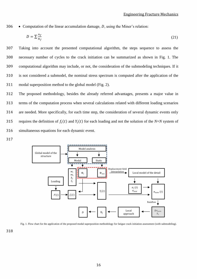
Taking into account the presented computational algorithm, the steps sequence to assess the 307
necessary number of cycles to the crack initiation can be summarized as shown in Fig. 1. The 308
computational algorithm may include, or not, the consideration of the submodeling techniques. If it 309
is not considered a submodel, the nominal stress spectrum is computed after the application of the 310
modal superposition method to the global model (Fig. 2). 311
The proposed methodology, besides the already referred advantages, presents a major value in 312
terms of the computation process when several calculations related with different loading scenarios 313
are needed. More specifically, for each time step, the consideration of several dynamic events only 314
requires the definition of 𝑓𝑖(𝑡) and 𝑌𝑖(𝑡) for each loading and not the solution of the N×N system of 315
simultaneous equations for each dynamic event. 316
317
Fig. 1. Flow chart for the application of the proposed modal superposition methodology for fatigue crack initiation assessment (with submodeling).
318
Global model of the structure
Modal Static
Model analysis
𝑤𝑖 𝑚𝑖 𝑘𝑖 𝜉𝑖
Φ𝑖 Φ𝑠𝑡𝑎
𝑓𝑖(𝑡) 𝐹(𝑡)
Loading
𝑌𝑖(𝑡)
Local model of the detail
Local approach
𝑁𝑓
𝜎𝑖 (𝑡) 𝜎𝑠𝑡𝑎𝑡 𝜎𝑛𝑜𝑚 (𝑡)
Rainflow
𝐷
Displacement field interpolation
Engineering Fracture Mechanics
17
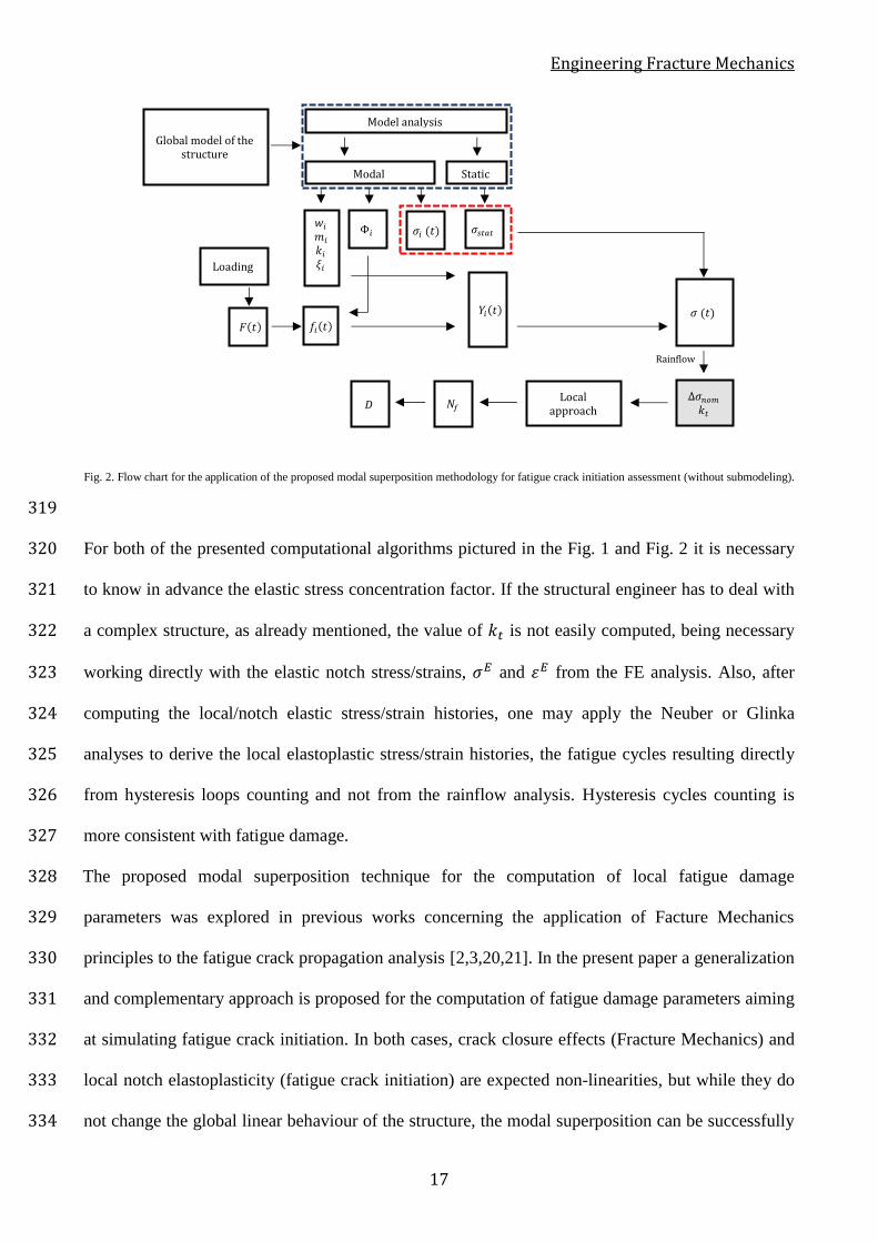
Fig. 2. Flow chart for the application of the proposed modal superposition methodology for fatigue crack initiation assessment (without submodeling).
319
For both of the presented computational algorithms pictured in the Fig. 1 and Fig. 2 it is necessary 320
to know in advance the elastic stress concentration factor. If the structural engineer has to deal with 321
a complex structure, as already mentioned, the value of 𝑘𝑡 is not easily computed, being necessary 322
working directly with the elastic notch stress/strains, 𝜎𝐸 and 𝜀𝐸 from the FE analysis. Also, after 323
computing the local/notch elastic stress/strain histories, one may apply the Neuber or Glinka 324
analyses to derive the local elastoplastic stress/strain histories, the fatigue cycles resulting directly 325
from hysteresis loops counting and not from the rainflow analysis. Hysteresis cycles counting is 326
more consistent with fatigue damage. 327
The proposed modal superposition technique for the computation of local fatigue damage 328
parameters was explored in previous works concerning the application of Facture Mechanics 329
principles to the fatigue crack propagation analysis [2,3,20,21]. In the present paper a generalization 330
and complementary approach is proposed for the computation of fatigue damage parameters aiming 331
at simulating fatigue crack initiation. In both cases, crack closure effects (Fracture Mechanics) and 332
local notch elastoplasticity (fatigue crack initiation) are expected non-linearities, but while they do 333
not change the global linear behaviour of the structure, the modal superposition can be successfully 334
𝜎𝑖 (𝑡)
Global model of the structure
Modal Static
Model analysis
𝑤𝑖 𝑚𝑖 𝑘𝑖 𝜉𝑖
Φ𝑖 𝜎𝑠𝑡𝑎𝑡
𝑓𝑖(𝑡) 𝐹(𝑡)
Loading
𝑌𝑖(𝑡)
∆𝜎𝑛𝑜𝑚 𝑘𝑡
Local approach
𝑁𝑓
𝜎 (𝑡)
Rainflow
𝐷
\\\
Engineering Fracture Mechanics
18
applied. For large structures the fatigue crack initiation process does not influence the global 335
behaviour of the structure, therefore modal analysis only needs to be performed one time. However, 336
when fatigue crack propagation is performed, it is worthwhile to refer that the propagating fatigue 337
crack may change the global behaviour of the structure which may require periodic updates of the 338
structural vibration modes. 339
340
3. Crack initiation assessment – application to a notched structural member 341
In order to validate the applicability of the modal superposition methodology for fatigue crack 342
initiation assessment, a numerical model of a notched simple structure was developed and duly 343
characterized from a geometric and material point of view. According to the computational 344
algorithm presented in the section 2.4, the flow chart pictured in Fig. 2 was implemented, i.e., the 345
explicit submodelling was not applied. The option for a simple structure was taken in order to 346
control all the parameters with direct or indirect influence in the structural dynamic behaviour. 347
The effectiveness of the proposed methodology is naturally dependent on the analytical 348
elastoplastic approach considered, hence the referred influence was tested through the consideration 349
of the Neuber [12] and Glinka [13-15] proposals. Instead of kt-𝜎𝑛𝑜𝑚 based elastoplastic 350
formulations, elastoplastic analyses formulated from the local elastic stress/strain computed directly 351
from the finite element model, Equations (18)-(19), are used. 352
The finite element model was submitted to dynamic loadings with variable intensity obtained 353
through the moving loads approach. The dynamic analyses were carried out using the proposed 354
modal superposition methodology with post-processing elastoplastic analysis and HHT algorithm 355
[18] coupled with elastoplastic material behaviour, being compared the obtained stress-strain 356
diagrams. Additionally, the necessary number of cycles to the crack initiation, 𝑁𝑓 , is computed 357
using the Morrow approach [10]. The extension of local plastic volume is also evaluated and 358
commented as regards the reliability of the simulated modal superposition methodology. 359
Engineering Fracture Mechanics
19
360
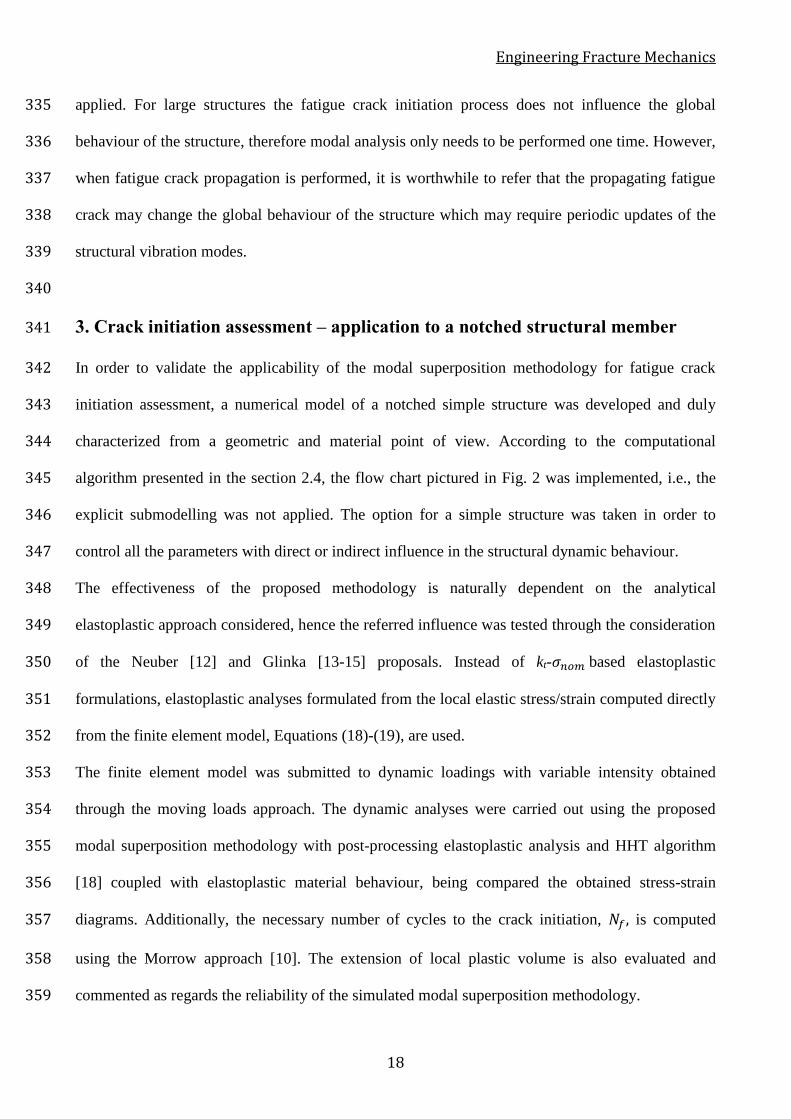
3.1. Structure description 361
A notched simply supported steel beam, with a 10m span and a HEB 700 cross section was 362
idealised. At mid span a circular hole with 10mm of radius was admitted to simulate a notch/defect 363
on the inferior flange. The numerical model was conceived using the ANSYS software [27] (Fig. 364
3). 365
Fig. 3. Finite element model of a simple supported beam with a circular hole at the lower flange.
366
The finite element model was built with 20-node brick elements with mesh refinement on the 367
notched zone to improve the description of the local stress and strain fields [28]. The beam is 368
assumed of S355 steel which was characterized in terms of elastoplastic behaviour and fatigue by 369
De Jesus et al. [29]. In the HHT analysis, the material is assumed elastoplastic in a central length of 370
4m of the bottom flange and web. The remaining of the structure was assumed linear elastic with 371
the same density (𝜌), Young modulus (𝐸) and Poisson ratio (𝜐) of the elastoplastic material. These 372
two materials option corresponds to a partial submodelling that helps numerical convergence and 373
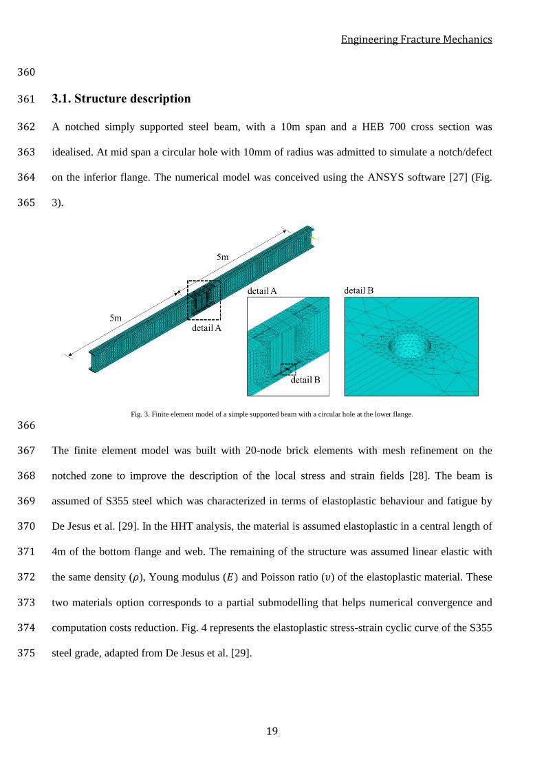
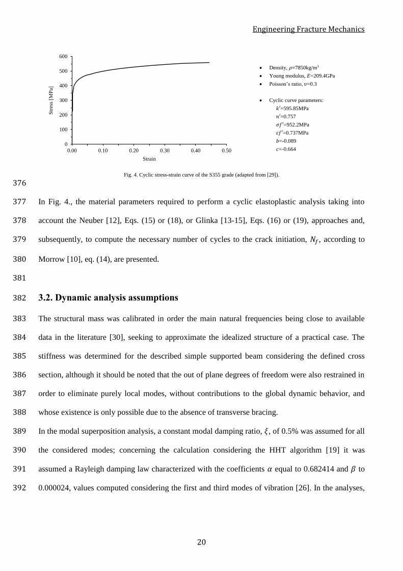
computation costs reduction. Fig. 4 represents the elastoplastic stress-strain cyclic curve of the S355 374
steel grade, adapted from De Jesus et al. [29]. 375
Engineering Fracture Mechanics
20
• Density, 𝜌=7850kg/m3
• Young modulus, 𝐸=209.4GPa
• Poisson’s ratio, 𝜐=0.3
• Cyclic curve parameters:
𝑘′=595.85MPa
𝑛′=0.757
𝜎𝑓′=952.2MPa
𝜀𝑓′=0.737MPa
𝑏=-0.089
𝑐=-0.664
Fig. 4. Cyclic stress-strain curve of the S355 grade (adapted from [29]).
376
In Fig. 4., the material parameters required to perform a cyclic elastoplastic analysis taking into 377
account the Neuber [12], Eqs. (15) or (18), or Glinka [13-15], Eqs. (16) or (19), approaches and, 378
subsequently, to compute the necessary number of cycles to the crack initiation, 𝑁𝑓, according to 379
Morrow [10], eq. (14), are presented. 380
381
3.2. Dynamic analysis assumptions 382
The structural mass was calibrated in order the main natural frequencies being close to available 383
data in the literature [30], seeking to approximate the idealized structure of a practical case. The 384
stiffness was determined for the described simple supported beam considering the defined cross 385
section, although it should be noted that the out of plane degrees of freedom were also restrained in 386
order to eliminate purely local modes, without contributions to the global dynamic behavior, and 387
whose existence is only possible due to the absence of transverse bracing. 388
In the modal superposition analysis, a constant modal damping ratio, 𝜉, of 0.5% was assumed for all 389
the considered modes; concerning the calculation considering the HHT algorithm [19] it was 390
assumed a Rayleigh damping law characterized with the coefficients 𝛼 equal to 0.682414 and 𝛽 to 391
0.000024, values computed considering the first and third modes of vibration [26]. In the analyses, 392
0
100
200
300
400
500
600
0.00 0.10 0.20 0.30 0.40 0.50
Str
ess
[MP
a]
Strain
Engineering Fracture Mechanics
21
a time step increment, ∆𝑡, equal to 0.0001s and a residual free vibration period of 0.1s were 393
admitted. 394
Taking into account the simplicity of the structure, it was expected a small number of modes to 395
contributed significantly to the total dynamic response. A sensitivity analysis allowed to prove such 396
assumption, being considered only the first 5 vibration modes to capture accurately the total 397
structural response. 398
399
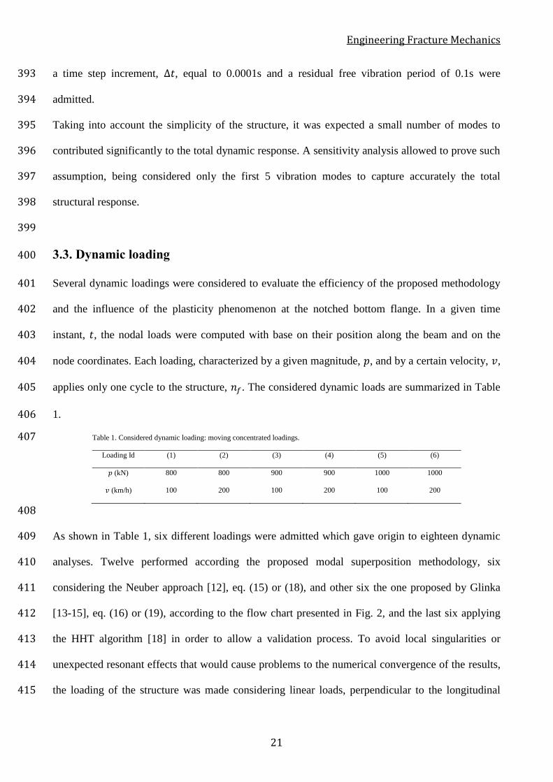
3.3. Dynamic loading 400
Several dynamic loadings were considered to evaluate the efficiency of the proposed methodology 401
and the influence of the plasticity phenomenon at the notched bottom flange. In a given time 402
instant, 𝑡, the nodal loads were computed with base on their position along the beam and on the 403
node coordinates. Each loading, characterized by a given magnitude, 𝑝, and by a certain velocity, 𝑣, 404
applies only one cycle to the structure, 𝑛𝑓. The considered dynamic loads are summarized in Table 405
1. 406
Table 1. Considered dynamic loading: moving concentrated loadings. 407
Loading Id (1) (2) (3) (4) (5) (6)
𝑝 (kN) 800 800 900 900 1000 1000
𝑣 (km/h) 100 200 100 200 100 200
408
As shown in Table 1, six different loadings were admitted which gave origin to eighteen dynamic 409
analyses. Twelve performed according the proposed modal superposition methodology, six 410
considering the Neuber approach [12], eq. (15) or (18), and other six the one proposed by Glinka 411
[13-15], eq. (16) or (19), according to the flow chart presented in Fig. 2, and the last six applying 412
the HHT algorithm [18] in order to allow a validation process. To avoid local singularities or 413
unexpected resonant effects that would cause problems to the numerical convergence of the results, 414
the loading of the structure was made considering linear loads, perpendicular to the longitudinal 415
Engineering Fracture Mechanics
22
direction of the beam, with 0.085m of development. The resultants of the linear loads were equal to 416
the magnitude, 𝑝. 417
The implementation of the Neuber and Glinka approaches were made using the Fatigue Life 418
Prediction –FLP software developed by Silva [31]. 419
420
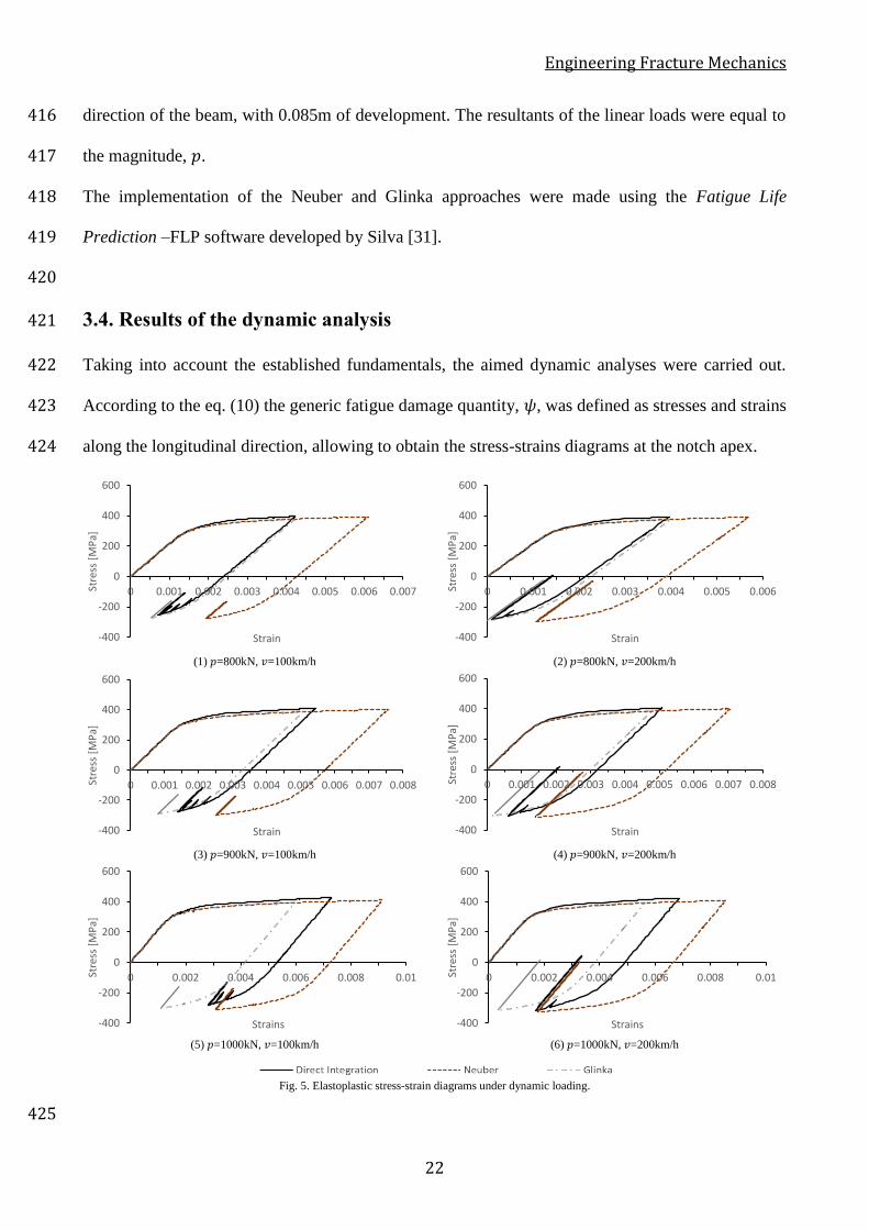
3.4. Results of the dynamic analysis 421
Taking into account the established fundamentals, the aimed dynamic analyses were carried out. 422
According to the eq. (10) the generic fatigue damage quantity, 𝜓, was defined as stresses and strains 423
along the longitudinal direction, allowing to obtain the stress-strains diagrams at the notch apex. 424
(1) 𝑝=800kN, 𝑣=100km/h (2) 𝑝=800kN, 𝑣=200km/h
(3) 𝑝=900kN, 𝑣=100km/h (4) 𝑝=900kN, 𝑣=200km/h
(5) 𝑝=1000kN, 𝑣=100km/h (6) 𝑝=1000kN, 𝑣=200km/h
Fig. 5. Elastoplastic stress-strain diagrams under dynamic loading.
425
-400
-200
0
200
400
600
0 0.001 0.002 0.003 0.004 0.005 0.006 0.007Stre
ss [
MP
a]
Strain -400
-200
0
200
400
600
0 0.001 0.002 0.003 0.004 0.005 0.006Stre
ss [
MP
a]
Strain
-400
-200
0
200
400
600
0 0.001 0.002 0.003 0.004 0.005 0.006 0.007 0.008Stre
ss [
MP
a]
Strain -400
-200
0
200
400
600
0 0.001 0.002 0.003 0.004 0.005 0.006 0.007 0.008Stre
ss [
MP
a]
Strain
-400
-200
0
200
400
600
0 0.002 0.004 0.006 0.008 0.01Stre
ss [
MP
a]
Strains -400
-200
0
200
400
600
0 0.002 0.004 0.006 0.008 0.01Stre
ss [
MP
a]
Strains
Engineering Fracture Mechanics
23
In Fig.5, it is possible to observe, for the loadings (1), (2), (3) and (4), a notorious agreement 426
between the obtained stress-strain diagrams through the modal superposition combined with the 427
Glinka approach [13-15] and the results of the direct time integrations using the HHT algorithm 428
[19]. A discrepancy between the results was found when the modal superposition was use together 429
with the Neuber approach [12], the Neuber approach resulting in higher average strains which is 430
consistent with the conservatism usually associated to this rule. Therefore, despite the plasticity 431
phenomenon, it was possible for the referred loadings to achieve satisfactory agreement in the 432
stress-strain diagrams with the modal superposition analysis plus Glinka approach. In the cases of 433
the loadings (5) and (6), the increment on the magnitude, 𝑝, resulted in the development of larger 434
plastic zones, which explain the progressive discrepancy between the stress-strain diagrams from 435
the two dynamic analyses. 436
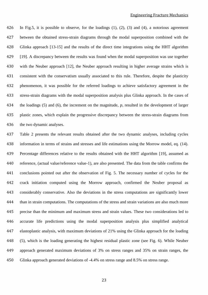
Table 2 presents the relevant results obtained after the two dynamic analyses, including cycles 437
information in terms of strains and stresses and life estimations using the Morrow model, eq. (14). 438
Percentage differences relative to the results obtained with the HHT algorithm [19], assumed as 439
reference, (actual value/reference value-1), are also presented. The data from the table confirms the 440
conclusions pointed out after the observation of Fig. 5. The necessary number of cycles for the 441
crack initiation computed using the Morrow approach, confirmed the Neuber proposal as 442
considerably conservative. Also the deviations in the stress computations are significantly lower 443
than in strain computations. The computations of the stress and strain variations are also much more 444
precise than the minimum and maximum stress and strain values. These two considerations led to 445
accurate life predictions using the modal superposition analysis plus simplified analytical 446
elastoplastic analysis, with maximum deviations of 21% using the Glinka approach for the loading 447
(5), which is the loading generating the highest residual plastic zone (see Fig. 6). While Neuber 448
approach generated maximum deviations of 3% on stress ranges and 35% on strain ranges, the 449
Glinka approach generated deviations of -4.4% on stress range and 8.5% on stress range. 450
Engineering Fracture Mechanics
24
451
452
Table 2. Relevant results of the dynamic and fatigue analysis. 453
Loading # 𝜎𝑚𝑎𝑥
(MPa)
𝜎𝑚𝑖𝑛 (MPa)
𝜎𝑚 (MPa)
∆𝜎 (MPa)
𝜀𝑚𝑎𝑥 𝜀𝑚𝑖𝑛 𝜀𝑚 ∆𝜀
𝑁𝑓
(1)
𝑝=800kN
𝑣=100km/h
HHT 396.25 -257.27 69.49 653.52
0.00423 0.00070 0.00247 0.00353
57953
Neuber 394.31 -278.84 57.73 673.15
0.00610 0.00193 0.00402 0.00417
34387
∆% -0.5% 8.4% -16.9% 3.0%
44.2% 175.7% 62.8% 18.1%
-40.7%
Glinka 378.36 -273.66 52.35 652.02
0.00423 0.00052 0.00238 0.00371
48937
∆% -4.5% 6.4% -24.7% -0.2%
0.0% -25.7% -3.6% 5.1%
-15.6%
(2)
𝑝=800kN
𝑣=200km/h
HHT 392.94 -282.37 55.28 675.31
0.00396 0.00010 0.00203 0.00387
39407
Neuber 391.47 -298.11 46.68 689.58
0.00570 0.00106 0.00338 0.00464
21457
∆% -0.4% 5.6% -15.6% 2.1%
43.9% 960.0% 66.5% 19.9%
-45.6%
Glinka 375.70 -290.74 42.48 666.45
0.00400 -0.00001 0.00199 0.00401
35144
∆% -4.4% 3.0% -23.2% -1.3%
1.0% -110.0% -2.0% 3.6%
-10.8%
(3)
𝑝=900kN
𝑣=100km/h
HHT 410.45 -274.78 67.83 685.23
0.00543 0.00139 0.00341 0.00404
30661
Neuber 402.99 -298.41 52.29 701.39
0.00757 0.00251 0.00504 0.00506
15250
∆% -1.8% 8.6% -22.9% 2.4%
39.4% 80.6% 47.8% 25.2%
-50.3%
Glinka 386.47 -290.44 48.01 676.91
0.00507 0.00080 0.00294 0.00427
26074
∆% -5.8% 5.7% -29.2% -1.2%
-6.6% -42.4% -13.8% 5.7%
-15.0%
(4)
𝑝=800kN
𝑣=200km/h
HHT 406.20 -304.26 50.97 710.45
0.00508 0.00060 0.00284 0.00448
21022
Neuber 400.21 -315.06 42.57 715.27
0.00706 0.00139 0.00423 0.00566
10208
∆% -1.5% 3.5% -16.5% 0.7%
39.0% 131.7% 48.9% 26.3%
-51.4%
Glinka 383.88 -305.45 39.21 689.33
0.00478 0.00014 0.00246 0.00463
19169
∆% -5.5% 0.4% -23.1% -3.0%
-5.9% -76.7% -13.4% 3.3%
-8.8%
(5)
𝑝=1000kN
𝑣=100km/h
HHT 426.93 -284.07 71.43 711.00
0.00729 0.00280 0.00504 0.00449
19658
Neuber 410.32 -312.74 48.79 723.05
0.00914 0.00308 0.00611 0.00606
8157
∆% -3.9% 10.1% -31.7% 1.7%
25.4% 10.0% 21.2% 35.0%
-58.5%
Glinka 393.38 -302.97 45.20 696.35
0.00597 0.00109 0.00353 0.00487
15531
∆% -7.9% 6.7% -36.7% -2.1%
-18.1% -61.1% -30.0% 8.5%
-21.0%
(6)
𝑝=1000kN
𝑣=200km/h
HHT 423.84 -316.37 53.73 740.21
0.00687 0.00168 0.00428 0.00519
12114
Neuber 407.75 -327.64 40.05 735.40
0.00855 0.00175 0.00515 0.00680
5735
∆% -3.8% 3.6% -25.5% -0.6%
24.5% 4.2% 20.3% 31.0%
-52.7%
Glinka 390.96 -316.60 37.18 707.56
0.00563 0.00032 0.00297 0.00531
11650
∆% -7.8% 0.1% -30.8% -4.4%
-18.0% -81.0% -30.6% 2.3%
-3.8%
454
455
Engineering Fracture Mechanics
25
(1) 𝑝=800kN, 𝑣=100km/h (2) 𝑝=800kN, 𝑣=200km/h
(3) 𝑝=900kN, 𝑣=100km/h (4) 𝑝=900kN, 𝑣=200km/h
(5) 𝑝=1000kN, 𝑣=100km/h (6) 𝑝=1000kN, 𝑣=200km/h
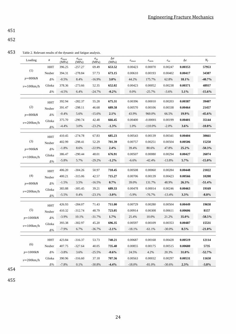
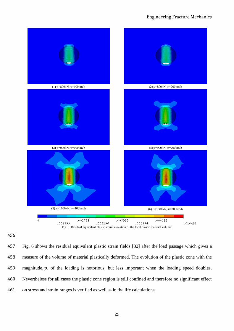
Fig. 6. Residual equivalent plastic strain, evolution of the local plastic material volume.
456
Fig. 6 shows the residual equivalent plastic strain fields [32] after the load passage which gives a 457
measure of the volume of material plastically deformed. The evolution of the plastic zone with the 458
magnitude, 𝑝, of the loading is notorious, but less important when the loading speed doubles. 459
Nevertheless for all cases the plastic zone region is still confined and therefore no significant effect 460
on stress and strain ranges is verified as well as in the life calculations. 461
Engineering Fracture Mechanics
26
462
4. Concluding remarks 463
The fatigue damage is a structural problem that is fundamental to assess in order to extend the 464
operational life of the existing structures. The scale of large structures puts significant problems in 465
terms of numerical modelling and structural analysis, particularly in what refers to the application 466
of local models to fatigue. 467
The obtained results, after the validation of the proposed modal superposition technique for fatigue 468
crack initiation assessment, allow concluding that they are promising for the analysis of more 469
complex structural problems. The proposed technique presented in the present paper, under the 470
condition of localized plasticity, combined with the work of Albuquerque et al. [20,21] enables the 471
structural engineer to fully assess the fatigue phenomenon using the modal superposition method. 472
The consideration of the approached technique permits to optimize the calculation process, making 473
possible the dynamic structural analysis in an affordable computational time. Regarding the simple 474
structure idealized and considering the assumption underlying the dynamic analysis, the calculation 475
involving the proposed technique took 10 seconds to compute the stress and strain results, while the 476
application of the HHT algorithm spent more than 5 hours, such difference giving a clear 477
quantification of the potential of the proposed technique. Moreover, the use of this method 478
conjugated with submodelling techniques can increase the accuracy and efficiency of refined 479
analysis of complex notched details, which means the computation of the local stress and strain data 480
required to assess the fatigue crack initiation at notches. The modal superposition analysis with the 481
Glinka elastoplastic post-processing is more precise than using the Neuber post-processing. 482
Further studies for more complex structures are needed, in particularly, the evaluation of the 483
accuracy of the results when contact non-linearities are present at the notched area (e.g. riveted 484
joints). 485
486
Engineering Fracture Mechanics
27
Acknowledgments 487
Authors acknowledge the Portuguese Foundation for Science and Technology for the funding, 488
particularly through the iRail doctoral program and the grants PD/BD/114101/2015 and 489
SFRH/BPD/107825/2015. Authors gratefully acknowledge the funding of SciTech - Science and 490
Technology for Competitive and Sustainable Industries (NORTE-01-0145-FEDER-000022), R&D 491
project co-financed by Programa Operacional Regional do Norte. 492
493
References 494
[1] CEN, Eurocode 3: Design of steel structures - Part 1-9: fatigue strength of steel strucutres, 495
(2005). 496
[2] C. Albuquerque, Advanced Methodologies for the Assessment of the Fatigue Behaviour of 497
Railway Bridges, Phd Thesis, Faculty of Engineering of the University of Porto, 2015. 498
[3] A.L.L. Silva, Advanced Methodologies for the Fatigue Analysis of Representative Details of 499
Metallic Bridges, Phd Thesis, Faculty of Engineering of the University of Porto, 2015. 500
[4] R.M. Teixeira, Metodologias para Modelagem e Análise da Fadiga em Ligações Rebitadas 501
com Aplicação em Pontes Metálicas Ferroviárias, Phd Thesis, Escola Politécnica da 502
Universidade de São Paulo, 2015. 503
[5] D. Radaj, C.M. Sonsino, W. Fricke, Fatigue Assessment of Welded Joints by Local 504
Approaches, Woodhead publishing, 2006. 505
[6] O.H. Basquin, The Exponential Law of Endurance Tests, Am. Soc. Test. Mater. Proc. Vol. 506
10 (1910) 625–630. 507
[7] L.F. Coffin, A Study of the Effects of the Cyclic Thermal Stresses on a Ductile metal, Trans. 508
ASME. Vol. 76 (1954) 931–950. 509
[8] S.S. Manson, Behaviour of Materials under Conditions of Thermal Stress, NACA, USA, 510
1954. 511
Engineering Fracture Mechanics
28
[9] J. Morrow, Cyclic Plastic Strain Energy and Fatigue of Metals, in: Intern. Frict. Damping, 512
Cycl. Plast., ASTM International, 1965: pp. 45–87. doi:10.1520/STP43764S. 513
[10] J. Morrow, Fatigue design handbook, in: Fatigue Prop. Met., No. AE-4, Society of 514
Automotive Engineers, Warrendale, PA., 1968: pp. 21–29. 515
[11] W. Ramberg, W.R. Osgood, Description of stress-strain curves by three parameters, (1943). 516
[12] H. Neuber, Theory of stress concentration for shear-strained prismatical bodies with arbitrary 517
nonlinear stress-strain law, J. Appl. Mech. 28 (1961) 544–550. 518
[13] G. Glinka, Energy density approach to calculation of inelastic strain-stress near notches and 519
cracks, Eng. Fract. Mech. 22 (1985) 485–508. doi:http://dx.doi.org/10.1016/0013-520
7944(85)90148-1. 521
[14] G. Glinka, Calculation of inelastic notch-tip strain-stress histories under cyclic loading, Eng. 522
Fract. Mech. 22 (1985) 839–854. doi:http://dx.doi.org/10.1016/0013-7944(85)90112-2. 523
[15] G. Glinka, Relations Between the Strain Energy Density Distribution and Elastic-Plastic 524
Stress-Strain Fields Near Cracks and Notches and Fatigue Life Calculation, ASTM STP 942. 525
(1988) 1022–1047. doi:10.1520/STP24538S. 526
[16] D. Broek, Elementary Engineering Fracture Mechanics, 3rd ed., Martinus Nijhoff Publishers, 527
The Hague, Netherlands, 1982. 528
[17] C.A.G. de M. Branco, A.A. Fernandes, P.M.S.T. de Castro, Fadiga de Estruturas Soldadas, 2a 529
ed, Fundação Calouste Gulbenkian, Lisboa, 1999. 530
[18] K.-J. Bathe, Finite Element Procedures, Prentice Hall Inc, New Jersey, 1996. 531
[19] J. Chung, G.M. Hulbert, A time integration algorithm for structural dynamics with improved 532
numerical dissipation: the generalized-α method, J. Appl. Mech. 60 (1993) 371–375. 533
[20] C. Albuquerque, P.M.S.T. de Castro, R. Calçada, Efficient crack analysis of dynamically 534
loaded structures using a modal superposition of stress intensity factors, Eng. Fract. Mech. 93 535
(2012) 75–91. doi:http://dx.doi.org/10.1016/j.engfracmech.2012.06.009. 536
Engineering Fracture Mechanics
29
[21] C. Albuquerque, A.L.L. Silva, A.M.P. de Jesus, R. Calçada, An efficient methodology for 537
fatigue damage assessment of bridge details using modal superposition of stress intensity 538
factors, Int. J. Fatigue. 81 (2015) 61–77. 539
doi:http://dx.doi.org/10.1016/j.ijfatigue.2015.07.002. 540
[22] K. Kiss, L. Dunai, Stress history generation for truss bridges using multi-level models, 541
Comput. Struct. 78 (2000) 329–339. doi:10.1016/s0045-7949(00)00079-1. 542
[23] K. Kiss, L. Dunai, Fracture mechanics based fatigue analysis of steel bridge decks by two-543
level cracked models, Comput. Struct. 80 (2002) 2321–2331. doi:10.1016/s0045-544
7949(02)00254-7. 545
[24] H. Zhou, G. Shi, Y. Wang, H. Chen, G. De Roeck, Fatigue evaluation of a composite railway 546
bridge based on fracture mechanics through global-local dynamic analysis, J. Constr. Steel 547
Res. 122 (2016). doi:10.1016/j.jcsr.2016.01.014. 548
[25] Z.X. Li, T.Q. Zhou, T.H.T. Chan, Y. Yu, Multi-scale numerical analysis on dynamic 549
response and local damage in long-span bridges, Eng. Struct. 29 (2007) 1507–1524. 550
doi:http://dx.doi.org/10.1016/j.engstruct.2006.08.004. 551
[26] R.W. Clough, J. Penzien, Dynamics of structures, McGraw-Hill, 1975. 552
[27] ANSYS® Academic Research, Release 17.1, 2017. 553
[28] ANSYS® Academic Research, Release 17.1, Element Reference, Coupled Field Analysis 554
Guide, ANSYS, Inc., 2017. 555
[29] A.M.P. de Jesus, R. Matos, B.F.C. Fontoura, C. Rebelo, L. Simões da Silva, M. Veljkovic, A 556
comparison of the fatigue behavior between S355 and S690 steel grades, J. Constr. Steel Res. 557
79 (2012) 140–150. doi:http://dx.doi.org/10.1016/j.jcsr.2012.07.021. 558
[30] L.R.T. Melo, Estudo de Efeitos Dinâmicos de Pontes Ferroviárias considerando Interação 559
Veículo-Estrutura, Phd Thesis, Universidade de São Paulo, 2016. 560
[31] A.L.L. Silva, Fatigue behavior of an ancient bridge material under complex loads, Master 561

Engineering Fracture Mechanics
30
Thesis, Trás-os-Montes and Alto Douro University, 2009. 562
[32] ANSYS® Academic Research, Release 17.1, Theory Reference, Coupled Field Analysis 563
Guide, ANSYS, Inc., 2017. 564
565