FKM Guideline “Fracture Mechanics Proof of Strength for ...
10
FKM GUIDELINE “FRACTURE MECHANICS PROOF OF STRENGTH FOR ENGINEERING COMPONENTS” – OVERVIEW AND EXTENSION TOPICS 85 Welding in the World, Vol. 51, n° 5/6, 2007 1 OVERVIEW The FKM guidelines – Analytical strength assessment [1], and – Fracture mechanics proof of strength for engineering components [2] were developed in the working group “Component Strength” of the Research Committee on Mechanical Engineering (FKM, Germany) supported and sponsored by the German Federation of Industrial Research Associations “Otto von Guericke” (AiF). Both documents describe the assessment of compo- nents subjected to static and cyclic loading, the first one without considering defects using the conventional meth- ods of strength of materials, and the second one with considering defects using fracture mechanics methods. Both guidelines complement each other, and in addition software is available for each guideline. For the fracture mechanics guideline presented here, the PC software FracSafe [3] has been developed, which can be used in German and English. The guidelines are applicable for components made of steel, cast iron and light metal alloys at temperatures below creep temperature, and for welded structures. FKM GUIDELINE “FRACTURE MECHANICS PROOF OF STRENGTH FOR ENGINEERING COMPONENTS” – OVERVIEW AND EXTENSION TOPICS Doc. IIW-1807-07 (ex-doc. X-1600-06) recommended for publication by Commission X “Structural perfor- mances of welded joints – Fracture avoidance”. B. Pyttel 1 I. Varfolomeyev 2 M. Luke 2 C. Berger 1 D. Siegele 2 1 IfW-MPA TU Darmstadt 2 Fraunhofer IWM (Germany) ABSTRACT The German guideline “Fracture Mechanics Proof of Strength for Engineering Components” has been released in 2001 as a result of activities sponsored by the Research Committee on Mechanical Engineering (FKM), task group “Component Strength”. The guideline describes basics for the integrity assessment of cracked components sub- jected to static or cyclic loading and provides a step-by-step computational procedure for the use in engineering prac- tice. The guideline was formulated based on a number of national and international reference documents, in partic- ular SINTAP, R6, BS 7910 and DVS-2401, recent research results and some own key aspects. Since 2004 it is also available in English. The procedures and solutions of the guideline are implemented in the computer program FracSafe. The latest 3 rd edition of the guideline (2005) includes several new topics. These allow for the considera- tion of special effects at cyclic loading, mixed mode loading, dynamic (impact) loading, stress corrosion cracking, probabilistic aspects in fracture mechanics calculations. In addition, the compendium of the stress intensity factor and limit load solutions is extended and adjusted according to the state-of-the-art. Some new examples and case studies are included to demonstrate the application of the procedure to engineering problems. This paper gives an overview of the guideline and describes new features available since its 1 st edition. IIW-Thesaurus keywords: Corrosion; Evaluation; Failure; Fracture mechanics; Loading; Recommendations; Reference lists; Rules; Stress corrosion.
-
Upload
khangminh22 -
Category
Documents
-
view
1 -
download
0
Transcript of FKM Guideline “Fracture Mechanics Proof of Strength for ...
FKM GUIDELINE “FRACTURE MECHANICS PROOF OF STRENGTH FOR ENGINEERING COMPONENTS” – OVERVIEW AND EXTENSION TOPICS 85
Welding in the World, Vol. 51, n° 5/6, 2007
1 OVERVIEW
The FKM guidelines– Analytical strength assessment [1], and– Fracture mechanics proof of strength for engineeringcomponents [2]
were developed in the working group “ComponentStrength” of the Research Committee on MechanicalEngineering (FKM, Germany) supported and sponsored
by the German Federation of Industrial ResearchAssociations “Otto von Guericke” (AiF).
Both documents describe the assessment of compo-nents subjected to static and cyclic loading, the first onewithout considering defects using the conventional meth-ods of strength of materials, and the second one withconsidering defects using fracture mechanics methods.Both guidelines complement each other, and in additionsoftware is available for each guideline. For the fracturemechanics guideline presented here, the PC softwareFracSafe [3] has been developed, which can be used inGerman and English. The guidelines are applicable forcomponents made of steel, cast iron and light metalalloys at temperatures below creep temperature, andfor welded structures.
FKM GUIDELINE “FRACTURE MECHANICSPROOF OF STRENGTH FOR ENGINEERING
COMPONENTS” – OVERVIEWAND EXTENSION TOPICS
Doc. IIW-1807-07 (ex-doc. X-1600-06) recommendedfor publication by Commission X “Structural perfor-mances of welded joints – Fracture avoidance”.
B. Pyttel1 I. Varfolomeyev2 M. Luke2 C. Berger1 D. Siegele2
1 IfW-MPA TU Darmstadt2 Fraunhofer IWM
(Germany)
ABSTRACT
The German guideline “Fracture Mechanics Proof of Strength for Engineering Components” has been released in2001 as a result of activities sponsored by the Research Committee on Mechanical Engineering (FKM), task group“Component Strength”. The guideline describes basics for the integrity assessment of cracked components sub-jected to static or cyclic loading and provides a step-by-step computational procedure for the use in engineering prac-tice. The guideline was formulated based on a number of national and international reference documents, in partic-ular SINTAP, R6, BS 7910 and DVS-2401, recent research results and some own key aspects. Since 2004 it is alsoavailable in English. The procedures and solutions of the guideline are implemented in the computer programFracSafe. The latest 3rd edition of the guideline (2005) includes several new topics. These allow for the considera-tion of special effects at cyclic loading, mixed mode loading, dynamic (impact) loading, stress corrosion cracking,probabilistic aspects in fracture mechanics calculations. In addition, the compendium of the stress intensity factorand limit load solutions is extended and adjusted according to the state-of-the-art. Some new examples and casestudies are included to demonstrate the application of the procedure to engineering problems. This paper gives anoverview of the guideline and describes new features available since its 1st edition.
IIW-Thesaurus keywords: Corrosion; Evaluation; Failure; Fracture mechanics; Loading; Recommendations;Reference lists; Rules; Stress corrosion.
86 FKM GUIDELINE “FRACTURE MECHANICS PROOF OF STRENGTH FOR ENGINEERING COMPONENTS” – OVERVIEW AND EXTENSION TOPICS
The FKM guideline “Fracture mechanics proof ofstrength for engineering components” was formulatedbased on a number of national and international refer-ence documents, in particular SINTAP [4], R6 [5],BS 7910 [6] and DVS-2401 [7], The 1st and 2nd editionof the guideline included the assessment of components:– at static loading with respect to crack initiation, sta-ble crack growth, crack instability or plastic collapseusing the failure assessment diagram (FAD) and– at cyclic loading with respect to fatigue limit andfatigue crack growth using linear elastic fracture mechan-ics (LEFM).
The 3rd edition contains several essential extensions andsupplements aiming at considering special effects atcyclic loading, mixed mode loading, dynamic loading,stress corrosion cracking and probabilistic aspects infracture mechanics calculations. Note that most of theincluded new topics are hardly considered in nationalor international standards and that they are often stillunder research. The user has to be given assistance
with the guideline for solving his problems, but he hasto be aware that in most cases finding a solution takestime and money. The results from the new included top-ics have to be analysed more critically than the resultsbased on failure assessment procedures and practicalapplications of many years, which are the basis of the1st and 2nd editions.
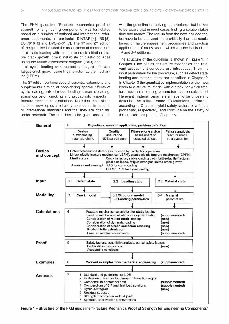
The structure of the guideline is shown in Figure 1. InChapter 1 the basics of fracture mechanics and rele-vant assessment concepts are introduced. Then theinput parameters for the procedure, such as defect state,loading and material state, are described in Chapter 2.In Chapter 3 the quantitative implementation of the inputleads to a structural model with a crack, for which frac-ture mechanics loading parameters can be calculated.Relevant material parameters have to be chosen todescribe the failure mode. Calculations performedaccording to Chapter 4 yield safety factors or a failureprobability, respectively, and conclude on the safety ofthe cracked component, Chapter 5.
Figure 1 – Structure of the FKM guideline “Fracture Mechanics Proof of Strength for Engineering Components”

FKM GUIDELINE “FRACTURE MECHANICS PROOF OF STRENGTH FOR ENGINEERING COMPONENTS” – OVERVIEW AND EXTENSION TOPICS 87
2 CALCULATION AT CYCLIC LOADING
In the previous editions, calculations at cyclic loadingare based on LEFM using the stress intensity factorrange ΔK. Crack propagation above threshold value ΔKth
can be described using an appropriate fatigue crackgrowth relationship, e.g. after Paris-Erdogan [8] or NAS-GROW [9]. The new edition includes a qualitative com-parison of several load interaction models at variableamplitude loading.
The calculation of crack propagation is now also possi-ble on the basis of elastic-plastic fracture mechanics(EPFM) using the cyclic J-Integral ΔJ and the effectivecyclic J-Integral ΔJeff, respectively. The procedure fol-lows the work of Vormwald [10, 11] and Dankert [12,13]. The cyclic J-Integral is calculated from local, elas-tic-plastic stress-strain parameters, as shown in Figure 2.In this approach load interaction effects are describedautomatically using load history dependent crack clo-sure stresses σcl and strains εcl.
The concept can also be used for short cracks and com-ponents without defects. For the latter, a fictitious initialcrack has to be defined. Crack growth propagation isthen calculated using a cyclic J-Integral ΔJ, e.g. after
da = CJ ⋅ (ΔJ )mJ (1)dN
with constants CJ and mJ. However, in most practicalapplications the stress intensity factor range ΔK is used.Separation of LEFM and EPFM regions can be done withthe help of a modified Kitagawa diagram, Figure 3. Theuse of ΔJ is therefore limited to components under highlocal stresses as they occur at notches or at small cracks.
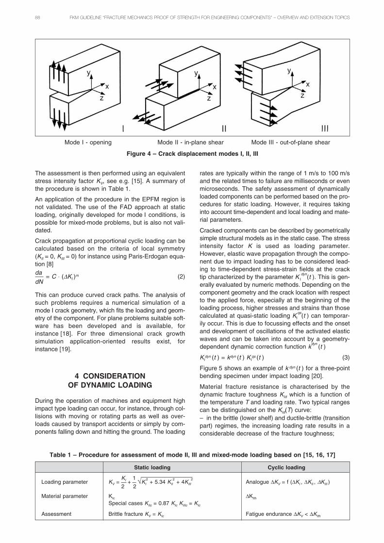
3 CONSIDERATIONOF MIXED MODE LOADING
According to the mode of loading and the resulted dis-placement components at the crack tip the followingmodes, Figure 4, are distinguished:
– Mode I - opening,
– Mode II - in-plane shear,
– Mode III - out-of-plane shear.
Mixed-mode loading results when due to componentgeometry, loading and the local crack tip orientation thecrack displacement modes I, II and/or III occur simul-taneously. The assessment procedure is based onLEFM and only proportional loading is considered. Thesingular parts of the stress-strain fields at the crack tipare described by the stress intensity factors KI, KII
and KIII. Selected solutions for stress intensity factorsare available in the annex part of the guideline. Thedevelopment of a simple calculable crack model fromthe defect state and the structural model from the load-ing state has to account for all stress components in thecrack plane. Rotating or projecting the defect in a ref-erence plane, as it is done in the previous editionswhere only mode I problems are considered, is notallowed.
Figure 2 – Definition of local stress-strainparameters
Figure 3 – Modified Kitagawa’s diagram for stress ratio R = – 1
88 FKM GUIDELINE “FRACTURE MECHANICS PROOF OF STRENGTH FOR ENGINEERING COMPONENTS” – OVERVIEW AND EXTENSION TOPICS
The assessment is then performed using an equivalentstress intensity factor KV, see e.g. [15]. A summary ofthe procedure is shown in Table 1.
An application of the procedure in the EPFM region isnot validated. The use of the FAD approach at staticloading, originally developed for mode I conditions, ispossible for mixed-mode problems, but is also not vali-dated.
Crack propagation at proportional cyclic loading can becalculated based on the criteria of local symmetry(KII = 0, KIII = 0) for instance using Paris-Erdogan equa-tion [8]da
= C ⋅ (ΔKI )m (2)dN
This can produce curved crack paths. The analysis ofsuch problems requires a numerical simulation of amode I crack geometry, which fits the loading and geom-etry of the component. For plane problems suitable soft-ware has been developed and is available, forinstance [18]. For three dimensional crack growthsimulation application-oriented results exist, forinstance [19].
4 CONSIDERATIONOF DYNAMIC LOADING
During the operation of machines and equipment highimpact type loading can occur, for instance, through col-lisions with moving or rotating parts as well as over-loads caused by transport accidents or simply by com-ponents falling down and hitting the ground. The loading
rates are typically within the range of 1 m/s to 100 m/sand the related times to failure are milliseconds or evenmicroseconds. The safety assessment of dynamicallyloaded components can be performed based on the pro-cedures for static loading. However, it requires takinginto account time-dependent and local loading and mate-rial parameters.
Cracked components can be described by geometricallysimple structural models as in the static case. The stressintensity factor K is used as loading parameter.However, elastic wave propagation through the compo-nent due to impact loading has to be considered lead-ing to time-dependent stress-strain fields at the cracktip characterized by the parameter K I
dyn(t ). This is gen-
erally evaluated by numeric methods. Depending on thecomponent geometry and the crack location with respectto the applied force, especially at the beginning of theloading process, higher stresses and strains than thosecalculated at quasi-static loading KI
qs(t ) can temporar-
ily occur. This is due to focussing effects and the onsetand development of oscillations of the activated elasticwaves and can be taken into account by a geometry-dependent dynamic correction function k
dyn(t )
KIdyn (t ) = kdyn (t ) KI
qs (t ) (3)
Figure 5 shows an example of k dyn (t ) for a three-pointbending specimen under impact loading [20].
Material fracture resistance is characterised by thedynamic fracture toughness KId which is a function ofthe temperature T and loading rate. Two typical rangescan be distinguished on the KId(T) curve:– in the brittle (lower shelf) and ductile-brittle (transitionpart) regimes, the increasing loading rate results in aconsiderable decrease of the fracture toughness;
Mode I - opening Mode II - in-plane shear Mode III - out-of-plane shear
Figure 4 – Crack displacement modes I, II, III
Static loading Cyclic loading
Loading parameter KV =KI +
1 √KI2
+ 5.34 KII2
+ 4KIII2
Analogue ΔKV = f (ΔKI , ΔKII , ΔKIII )2 2
Material parameter KIc ΔKIth
Special cases KIIc = 0.87 KIc KIIIc = KIc
Assessment Brittle fracture KV = KIc Fatigue endurance ΔKV < ΔKIth
Table 1 – Procedure for assessment of mode II, III and mixed-mode loading based on [15, 16, 17]

FKM GUIDELINE “FRACTURE MECHANICS PROOF OF STRENGTH FOR ENGINEERING COMPONENTS” – OVERVIEW AND EXTENSION TOPICS 89
– in the ductile (upper shelf) regime, the fracture tough-ness generally increases with the loading rate, so thata conservative failure assessment can be based on theuse of the quasi-static fracture resistance curve.
The dynamic fracture toughness should be determinedunder temperature and loading rate corresponding tothe component service conditions. The use of a dynamicmaster curve according to [21] is possible. Figure 6 com-pares the static and dynamic master curves for a pres-sure vessel steel [22]. A considerable embrittlementeffect can be noticed due to increasing loading rate.Alternatively the crack arrest curve KIa (ASTM E 1221)can be employed as a lower bound for KId.
Fracture assessment in the upper shelf regime can fol-low the procedure for the static loading. In the lowershelf and brittle-to-ductile transition regimes, the condi-tion
max {KIdyn
(t )} < KId (T, K̇ ) (4)
must be satisfied for a safe exclusion of crack initiation.Depending on the failure consequences, the accuracyin determining the load parameters and facture tough-ness, appropriate safety factors can be additionallyapplied.
5 CONSIDERATION OF STRESSCORROSION CRACKING
Stress corrosion cracking is crack initiation and propa-gation in materials under static tensile loading in a cor-rosive active medium. It is not possible to describe crackinitiation with fracture mechanics methods. In manycases crack propagation can be described with linear
Figure 5 – Dynamic correction function kdyn for impact-loaded three-point bending specimens [20]
Figure 6 – Static and dynamic master curve for the material 6JRQ43; crack tip loadingrate 2 × 10⁴ MPa√ms-1 [22]
a/W = 0,5L/W = 4,1
dimensionless time cl t/w
dyn
am
ic c
orr
ect
ion
fu
nct
ion
kdyn
cl =longitudinal elastic wavevelocity of the materialfor plane stress [m/s]t = time [s]
90 FKM GUIDELINE “FRACTURE MECHANICS PROOF OF STRENGTH FOR ENGINEERING COMPONENTS” – OVERVIEW AND EXTENSION TOPICS
elastic fracture mechanics methods, that means usingthe stress intensity factor K. Crack propagation occurs,when stress intensity is high, the corrosive medium isactive and the material susceptible to stress corrosion.Susceptible to stress corrosion are many material/medium combinations, some important are:– austenitic and austenitic-ferritic CrNi-steels in chlo-ride containing atmospheres,– high strength steels and high strength titanium alloysin atmospheres, which can emit hydrogen as for instanceH2O, H2S, NH3 and other acids,– mild steels and low alloyed steels in hot nitrate, car-bonate and sulfide solutions and bases,– aluminium alloys in chloride containing atmospheres(for instance water, seawater),– magnesium alloys in seawater,– copper alloys in ammonium, amin and nitride con-taining atmospheres, and– nickel alloys in nuclear reactors coolant (boiling water).
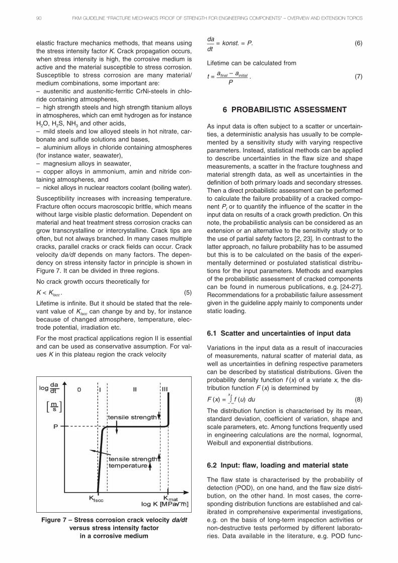
Susceptibility increases with increasing temperature.Fracture often occurs macroscopic brittle, which meanswithout large visible plastic deformation. Dependent onmaterial and heat treatment stress corrosion cracks cangrow transcrystalline or intercrystalline. Crack tips areoften, but not always branched. In many cases multiplecracks, parallel cracks or crack fields can occur. Crackvelocity da/dt depends on many factors. The depen-dency on stress intensity factor in principle is shown inFigure 7. It can be divided in three regions.
No crack growth occurs theoretically for
K < KIscc . (5)
Lifetime is infinite. But it should be stated that the rele-vant value of KIscc can change by and by, for instancebecause of changed atmosphere, temperature, elec-trode potential, irradiation etc.
For the most practical applications region II is essentialand can be used as conservative assumption. For val-ues K in this plateau region the crack velocity
da= konst. = P. (6)
dt
Lifetime can be calculated from
t = afinal – ainitial . (7)P
6 PROBABILISTIC ASSESSMENT
As input data is often subject to a scatter or uncertain-ties, a deterministic analysis has usually to be comple-mented by a sensitivity study with varying respectiveparameters. Instead, statistical methods can be appliedto describe uncertainties in the flaw size and shapemeasurements, a scatter in the fracture toughness andmaterial strength data, as well as uncertainties in thedefinition of both primary loads and secondary stresses.Then a direct probabilistic assessment can be performedto calculate the failure probability of a cracked compo-nent Pf or to quantify the influence of the scatter in theinput data on results of a crack growth prediction. On thisnote, the probabilistic analysis can be considered as anextension or an alternative to the sensitivity study or tothe use of partial safety factors [2, 23]. In contrast to thelatter approach, no failure probability has to be assumedbut this is to be calculated on the basis of the experi-mentally determined or postulated statistical distribu-tions for the input parameters. Methods and examplesof the probabilistic assessment of cracked componentscan be found in numerous publications, e.g. [24-27].Recommendations for a probabilistic failure assessmentgiven in the guideline apply mainly to components understatic loading.
6.1 Scatter and uncertainties of input data
Variations in the input data as a result of inaccuraciesof measurements, natural scatter of material data, aswell as uncertainties in defining respective parameterscan be described by statistical distributions. Given theprobability density function f (x) of a variate x, the dis-tribution function F (x) is determined by
F (x) = x
∫– ∞
f (u) du (8)
The distribution function is characterised by its mean,standard deviation, coefficient of variation, shape andscale parameters, etc. Among functions frequently usedin engineering calculations are the normal, lognormal,Weibull and exponential distributions.
6.2 Input: flaw, loading and material state
The flaw state is characterised by the probability ofdetection (POD), on one hand, and the flaw size distri-bution, on the other hand. In most cases, the corre-sponding distribution functions are established and cal-ibrated in comprehensive experimental investigations,e.g. on the basis of long-term inspection activities ornon-destructive tests performed by different laborato-ries. Data available in the literature, e.g. POD func-
Figure 7 – Stress corrosion crack velocity da/dtversus stress intensity factor
in a corrosive medium

FKM GUIDELINE “FRACTURE MECHANICS PROOF OF STRENGTH FOR ENGINEERING COMPONENTS” – OVERVIEW AND EXTENSION TOPICS 91
tions [23-26], reflect particular component geometry,NDE technique, material state and, therefore, are rarelytransferable to the specific case to be investigated.
The loading is preferably treated as a deterministic para-meter. However, uncertainties in the definition of resid-ual stresses as well as random amplitude fatigue load-ing can be rationally resolved by using statisticalmethods.
Material strength properties and especially the fracturetoughness are subject to considerable scatter which hasto be accounted for in a probabilistic analysis. The useof the master curve [21] is an example of a probabilis-tic treatment of the fracture toughness in failure analy-ses.
6.3 Computation of the failure probability
A Monte Carlo simulation (MCS) is recommended tocompute high failure probabilities, e.g. above 10 –3...10 –5.Given statistical distributions for the input parameters(vector X) and the limit state function g (X) separatingthe safe and unsafe regimes, certain number N of deter-ministic calculations are performed for randomly selectedinput data. The number Nf of failure cases in relation tothe total number of simulations gives an approximatevalue of the failure probability
Pf =Nf (9)N
which converges to the “exact” value with increasingnumber of simulations.
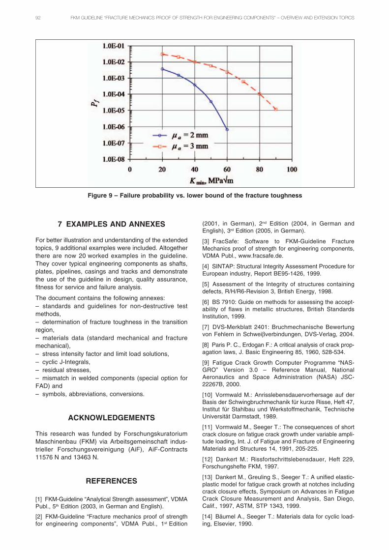
Figure 8 shows an example of the probabilistic failureassessment for a pipeline with a spiral weld using theFAD approach and MCS. A long surface crack was pos-tulated on the outer surface, in the weld. Different sta-tistical distributions were assumed for the crack depth,the primary and secondary stresses, the yield and thetensile strength, and the fracture toughness. The limitstate function follows in this example the SINTAP rec-ommendations for the material with discontinuous yield-
ing. Using MCS with 103 to 106 simulations, failure prob-abilities of Pf = 4 × 10 –3 and Pf = 3 × 10 –2 were calcu-lated for the mean crack depth μa = 2 mm andμa = 3 mm, respectively.
At low failure probabilities usually requested for safetyrelevant components, the use of MCS becomes ratherinefficient due to extremely high computational time. Inthese cases the failure probability can be computeddirectly by applying the first- or second-order reliabilitymethods (FORM or SORM, respectively), or a modifiedMCS version, the Monte Carlo simulation with impor-tance sampling (MCS-IS). All these methods require thecomputation of the so-called design point which makesthe principal contribution to the analysis effort.
6.4 Interpretation of results, assessment
The calculated value of the failure probability essentiallydepends on the quality of input data. Both assumptionson the type of distribution functions with the relatedparameter fit and the selected method for computingthe failure probability may considerably affect the analy-sis result. Therefore, the absolute value of the failureprobability should be handled with particular care.Generally, a probabilistic assessment should be con-sidered as a reasonable supplement to the determinis-tic analysis, for instance, to study the impact of differ-ent input parameters and their variations on thecomponent integrity. Accordingly, in the example con-sidered above, the failure probability was shown to con-siderably depend on the crack size and the fracturetoughness. Further assuming the Weibull distribution forthe fracture toughness [21]
PKmat = 1 – exp – Kmat – Kmin β
(10)[ ( K0 – Kmin) ]
with K0 = 169 MPa√m and β = 4, the requested level offailure probability can be defined as a function of thelower bound fracture toughness Kmin, Figure 9.
Figure 8 – Probabilistic failure assessment in FAD
92 FKM GUIDELINE “FRACTURE MECHANICS PROOF OF STRENGTH FOR ENGINEERING COMPONENTS” – OVERVIEW AND EXTENSION TOPICS
7 EXAMPLES AND ANNEXES
For better illustration and understanding of the extendedtopics, 9 additional examples were included. Altogetherthere are now 20 worked examples in the guideline.They cover typical engineering components as shafts,plates, pipelines, casings and tracks and demonstratethe use of the guideline in design, quality assurance,fitness for service and failure analysis.
The document contains the following annexes:– standards and guidelines for non-destructive testmethods,– determination of fracture toughness in the transitionregion,– materials data (standard mechanical and fracturemechanical),– stress intensity factor and limit load solutions,– cyclic J-Integrals,– residual stresses,– mismatch in welded components (special option forFAD) and– symbols, abbreviations, conversions.
ACKNOWLEDGEMENTS
This research was funded by ForschungskuratoriumMaschinenbau (FKM) via Arbeitsgemeinschaft indus-trieller Forschungsvereinigung (AiF), AiF-Contracts11576 N and 13463 N.
REFERENCES
[1] FKM-Guideline “Analytical Strength assessment”, VDMAPubl., 5th Edition (2003, in German and English).
[2] FKM-Guideline “Fracture mechanics proof of strengthfor engineering components”, VDMA Publ., 1st Edition
(2001, in German), 2nd Edition (2004, in German andEnglish), 3rd Edition (2005, in German).
[3] FracSafe: Software to FKM-Guideline FractureMechanics proof of strength for engineering components,VDMA Publ., www.fracsafe.de.
[4] SINTAP: Structural Integrity Assessment Procedure forEuropean industry, Report BE95-1426, 1999.
[5] Assessment of the Integrity of structures containingdefects, R/H/R6-Revision 3, British Energy, 1998.
[6] BS 7910: Guide on methods for assessing the accept-ability of flaws in metallic structures, British StandardsInstitution, 1999.
[7] DVS-Merkblatt 2401: Bruchmechanische Bewertungvon Fehlern in Schweiβverbindungen, DVS-Verlag, 2004.
[8] Paris P. C., Erdogan F.: A critical analysis of crack prop-agation laws, J. Basic Engineering 85, 1960, 528-534.
[9] Fatigue Crack Growth Computer Programme “NAS-GRO” Version 3.0 – Reference Manual, NationalAeronautics and Space Administration (NASA) JSC-22267B, 2000.
[10] Vormwald M.: Anrisslebensdauervorhersage auf derBasis der Schwingbruchmechanik für kurze Risse, Heft 47,Institut für Stahlbau und Werkstoffmechanik, TechnischeUniversität Darmstadt, 1989.
[11] Vormwald M., Seeger T.: The consequences of shortcrack closure on fatigue crack growth under variable ampli-tude loading, Int. J. of Fatigue and Fracture of EngineeringMaterials and Structures 14, 1991, 205-225.
[12] Dankert M.: Rissfortschrittslebensdauer, Heft 229,Forschungshefte FKM, 1997.
[13] Dankert M., Greuling S., Seeger T.: A unified elastic-plastic model for fatigue crack growth at notches includingcrack closure effects, Symposium on Advances in FatigueCrack Closure Measurement and Analysis, San Diego,Calif., 1997, ASTM, STP 1343, 1999.
[14] Bäumel A., Seeger T.: Materials data for cyclic load-ing, Elsevier, 1990.
Figure 9 – Failure probability vs. lower bound of the fracture toughness
FKM GUIDELINE “FRACTURE MECHANICS PROOF OF STRENGTH FOR ENGINEERING COMPONENTS” – OVERVIEW AND EXTENSION TOPICS 93
[15] Erdogan F., Sih G. C.: On the crack extension in platesunder plane loading and plane shear, Journal of BasicEngineering 85, 1963.
[16] Richard A., Fulland M., Buchholz F. G., SchöllmannM.: 3D Fracture criteria for structures with cracks, SteelResearch 74, 2003, 491-497.
[17] Richard A., Fulland M., Sander M.: Theoretical crackpath prediction, Int. J. of Fatigue and Fracture ofEngineering Materials and Structures 28, 2005, 3-12.
[18] Theilig H., Wünsche M., Bergmann R.: Numerical andexperimental investigation of curved fatigue crack growthunder proportional cyclic loading, Steel Research 74, 2003,566-576.
[19] Dhondt G.: Cutting of 3D FE mesh for automatic modeI crack propagation calculation, Int. J. Num. Meth. Engng.42, 1998, 749-772.
[20] Böhme W.: Dynamic key-curves for brittle fractureimpact tests and establishment of a transition time, inFracture Mechanics: 21st Symposium, ASTM STP 1074, J.P. Gudas, J. A. Joyce and E. M. Hackett, Eds., AmericanSociety for Testing Materials, 1990, pp. 144-156.
[21] ASTM E 1921-02: Standard Test method for determi-nation of reference temperature, T0, for ferritic steels in thetransition range, ASTM International, West Conshohocken,PA 2002.
[22] Böhme W., Sreenivasan P. R., Sguaizer Y., BurdackM., Schüler L., Blauel J. G., Siegele D.: Determination ofmaster curve reference temperatures T0 using static anddynamic tests for RPV-material 6JRQ43, Fraunhofer IWM,Report S 9/2004, Freiburg, 2004.
[23] Burdekin F. M., Hamour W.: Partial safety factors forthe SINTAP procedure, Offshore Technology Report2000/020, AEA Technology Publ., 2002.
[24] Probabilistic fracture mechanics and fatigue methods:Applications for Structural Design and Maintenance, ASTMSTP 798, J. M. Bloom and J. C. Ekvall Eds., AmericanSociety for Testing and Materials, 1983.
[25] Probabilistic Fracture mechanics and reliability, J. W.Provan Ed., Martinus Nijhoff Publ., 1987.
[26] Wellein R.: Assessment of the reliability of the steelcontainment of a PWR by probabilistic fracture mechanics:distributions of material properties and defect dimensions,in Application of Fracture Mechanics to Materials andStructures, G. C. Sih, E. Sommer and W. Dahl, Eds.,Martinus Nijhoff Publ., 1984, pp. 559-570.
[27] Dillström P.: ProSINTAP – A probabilistic programimplementing the SINTAP assessment procedure, Eng.Fract. Mech. 67, 2000, 647-668.

本文献由“学霸图书馆-文献云下载”收集自网络,仅供学习交流使用。
学霸图书馆(www.xuebalib.com)是一个“整合众多图书馆数据库资源,
提供一站式文献检索和下载服务”的24 小时在线不限IP
图书馆。
图书馆致力于便利、促进学习与科研,提供最强文献下载服务。
图书馆导航:
图书馆首页 文献云下载 图书馆入口 外文数据库大全 疑难文献辅助工具