Effect of Antimony on Graphite Growth in Ductile Iron
9
EFFECT OF ANTIMONY ON GRAPHITE GROWTH IN DUCTILE IRON Lutz Dekker Stahlwerk Bous GmbH, Saarstraße, 66359 Bous, Germany Babette Tonn Institute of Metallurgy, Clausthal University of Technology, Robert-Koch-Str. 42, 38678 Clausthal-Zellerfeld, Germany Gerhard Lilienkamp Institute of Energy Research and Physical Technologies, Clausthal University of Technology, Leibnizstraße 4, 38678 Clausthal-Zellerfeld, Germany Copyright Ó 2020 The Author(s) https://doi.org/10.1007/s40962-020-00434-1 Abstract Antimony is used in ductile cast iron melts to avoid gra- phite degenerations like exploded graphite and chunky graphite. However, the effect of Sb in the melt on the crystallization of ductile cast iron is still unknown, there- fore the aim of our investigations. The current study pre- sents thermodynamic calculations showing that at the beginning of the eutectic solidification, Mg 3 Sb 2 is formed. Furthermore, the amount of Sb increases in the austenite and decreases in the remaining melt during solidification. An experiment was conducted, in which a higher amount of Sb than usual was added to a ductile iron melt. In the microstructure of the Sb-containing sample, a higher gra- phite precipitate count was measured than in the reference sample without Sb. The graphite spheroids of the Sb-con- taining sample show an almost perfect roundness and a very smooth surface. However, lamellar outgrowths from the graphite spheroids were also observed. Using scanning electron microscopy with energy-dispersive X-ray spec- troscopy, it could be shown that Sb-containing phases have been formed, which are located in the pearlitic matrix and also in graphite spheroids. As a result of spectroscopic investigations, it can be assumed that Sb-containing phases act as nucleant for graphite nucleation. Further investi- gations by Auger electron spectroscopy showed that a thin layer of Sb at the interface between graphite and matrix has been formed. It seems that this layer constricts the diffusion of carbon to the spheroidal graphite and acts as a surfactant favoring a layer-by-layer growth of the graphite spheroids. Keywords: ductile cast iron, antimony, graphite nucleation, graphite growth, auger electron spectroscopy Introduction During solidification of mostly thick-walled ductile iron castings, the graphite has a tendency to degenerate during eutectic growth, which results in exploded or even chunky graphite. Possible reasons are long solidification times, high amounts of Si and the presence of Ce in the melt. 1 According to References 2–4, small amounts of Pb, Bi or Sb in a defined stoichiometric ratio with Ce can neutralize the detrimental effects of Ce on graphite growth by form- ing intermetallic phases in the melt. That is why mainly in large ductile iron castings very small amounts of Sb between 20 and 40 ppm are added to the cast iron melt to avoid the formation of chunky graphite. Even in ductile cast irons without any Ce in the melt, the addition of Sb to the melt is a proven instrument to suppress these undesir- able graphite morphologies. This paper is an invited submission to IJMC selected from presen- tations at the 2nd Carl Loper 2019 Cast Iron Symposium held September 30 to October 1, 2019, in Bilbao, Spain. International Journal of Metalcasting
-
Upload
khangminh22 -
Category
Documents
-
view
0 -
download
0
Transcript of Effect of Antimony on Graphite Growth in Ductile Iron

EFFECT OF ANTIMONY ON GRAPHITE GROWTH IN DUCTILE IRON
Lutz DekkerStahlwerk Bous GmbH, Saarstraße, 66359 Bous, Germany
Babette TonnInstitute of Metallurgy, Clausthal University of Technology, Robert-Koch-Str. 42, 38678 Clausthal-Zellerfeld, Germany
Gerhard LilienkampInstitute of Energy Research and Physical Technologies, Clausthal University of Technology, Leibnizstraße 4, 38678
Clausthal-Zellerfeld, Germany
Copyright � 2020 The Author(s)
https://doi.org/10.1007/s40962-020-00434-1
Abstract
Antimony is used in ductile cast iron melts to avoid gra-
phite degenerations like exploded graphite and chunky
graphite. However, the effect of Sb in the melt on the
crystallization of ductile cast iron is still unknown, there-
fore the aim of our investigations. The current study pre-
sents thermodynamic calculations showing that at the
beginning of the eutectic solidification, Mg3Sb2 is formed.
Furthermore, the amount of Sb increases in the austenite
and decreases in the remaining melt during solidification.
An experiment was conducted, in which a higher amount of
Sb than usual was added to a ductile iron melt. In the
microstructure of the Sb-containing sample, a higher gra-
phite precipitate count was measured than in the reference
sample without Sb. The graphite spheroids of the Sb-con-
taining sample show an almost perfect roundness and a
very smooth surface. However, lamellar outgrowths from
the graphite spheroids were also observed. Using scanning
electron microscopy with energy-dispersive X-ray spec-
troscopy, it could be shown that Sb-containing phases have
been formed, which are located in the pearlitic matrix and
also in graphite spheroids. As a result of spectroscopic
investigations, it can be assumed that Sb-containing phases
act as nucleant for graphite nucleation. Further investi-
gations by Auger electron spectroscopy showed that a thin
layer of Sb at the interface between graphite and matrix
has been formed. It seems that this layer constricts the
diffusion of carbon to the spheroidal graphite and acts as a
surfactant favoring a layer-by-layer growth of the graphite
spheroids.
Keywords: ductile cast iron, antimony, graphite
nucleation, graphite growth, auger electron spectroscopy
Introduction
During solidification of mostly thick-walled ductile iron
castings, the graphite has a tendency to degenerate during
eutectic growth, which results in exploded or even chunky
graphite. Possible reasons are long solidification times,
high amounts of Si and the presence of Ce in the melt.1
According to References 2–4, small amounts of Pb, Bi or
Sb in a defined stoichiometric ratio with Ce can neutralize
the detrimental effects of Ce on graphite growth by form-
ing intermetallic phases in the melt. That is why mainly in
large ductile iron castings very small amounts of Sb
between 20 and 40 ppm are added to the cast iron melt to
avoid the formation of chunky graphite. Even in ductile
cast irons without any Ce in the melt, the addition of Sb to
the melt is a proven instrument to suppress these undesir-
able graphite morphologies.
This paper is an invited submission to IJMC selected from presen-
tations at the 2nd Carl Loper 2019 Cast Iron Symposium held
September 30 to October 1, 2019, in Bilbao, Spain.
International Journal of Metalcasting

Kovac5 and Liu et al.6 detected Sb at the interface between
graphite spheroids and matrix. Kovac assumed that Sb is
blocking the transfer of C from the melt or from austenite
to the spheroids. Liu et al. proposed that Sb acts as a
scavenger for the harmful effects of oxygen at the interface
between graphite spheroids and the melt.
However, there is no detailed knowledge about the effect
of Sb on the graphite growth during the solidification of
ductile iron melts. The present study was initiated to allow
further insights into the mechanism of Sb on the crystal-
lization of ductile iron melts.
Thermodynamic Calculations
Thermodynamic calculations using the THERMOCALC
database SSOL4 were performed to simulate the phase
formation as well as the distribution of Sb in the melt and
in the austenite during the solidification of ductile iron.
Here, a local thermodynamic equilibrium is assumed at the
interface between solid and liquid. Assuming full misci-
bility in liquid phase and complete suppression of diffusion
in solid phase, the Scheil–Gulliver model was used. For the
thermodynamic calculations, the elements Fe, C, Si, Mn,
Mg and Sb were considered. The element contents were
taken from the experiment of the Sb-containing melt and
are given in Table 2. Figure 1 shows the calculated for-
mation of solid phases during solidification.
The solidification starts with the formation of primary
austenite at a temperature of 1173 �C followed by the
eutectic solidification beginning at 1167 �C. Almost
simultaneously with the eutectic growth, the formation of
Mg3Sb2 starts at 1166 �C. No more Mg3Sb2 phase will be
formed from about 1150 �C until the end of solidification
due to a strongly decreasing Mg content in the liquid,
shown in Figure 2.
Figure 3 shows the calculated development of the amounts
of antimony in austenite and in the remaining liquid during
solidification. From the results, it can be assumed that Sb is
also solute in austenite.
Experimental
For the investigation of the effect of Sb on the graphite
morphology, a furan resin-based sand mold with two
rectangular-shaped cavities of 60 9 60 9 25 mm size was
prepared. For addition of Sb to the ductile cast iron melt, an
in-mold addition process was applied, which means that
into one of the cavities 1.9 g technically pure, fine-grained
Sb was placed. Such a high content of Sb was chosen in
order to increase the probability of detecting it in the
microstructure of ductile cast iron.
Furthermore, a ductile cast iron melt was prepared. The
base melt, consisting of pig iron, ductile iron returns and
steel scrap, was melted in a medium frequency induction
furnace with a melt capacity of 35 kg. FeSi75 and graphite
were added to reach the target chemical composition. The
melt was treated at 1505 �C with a Mg-containing master
alloy. The composition of the master alloy was determined
0
0,02
0,04
0,06
0,08
0,1
1120 1130 1140 1150 1160 1170 1180
Frac
tion
of s
olid
pha
ses
Liquid
FCC_A1
GRAPHITE
MG3SB2_HIGH
Figure 1. Calculated phase formation during solidifica-tion of ductile cast iron.
0
0,005
0,01
0,015
0,02
0,025
0,03
1120 1130 1140 1150 1160 1170 1180
Mas
s pe
rcen
t of M
g in
Liq
uid
Figure 2. Calculated amount of Mg in the melt duringsolidification of ductile iron.
0
0,05
0,1
0,15
0,2
0,25
1120 1130 1140 1150 1160 1170 1180
Mas
s pe
rcen
t of S
b in
a p
hase
Liquid
FCC
Figure 3. Calculated amount of Sb in the melt and inaustenite during solidification of ductile iron.
International Journal of Metalcasting
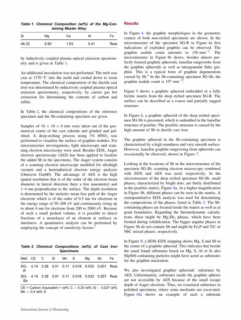
by inductively coupled plasma optical emission spectrom-
etry and is given in Table 1.
An additional inoculation was not performed. The melt was
cast at 1370 �C into the mold and cooled down to room
temperature. The chemical composition of the ductile cast
iron was determined by inductively coupled plasma optical
emission spectrometry, respectively, by carrier gas hot
extraction for determining the contents of carbon and
sulfur.
In Table 2, the chemical compositions of the reference
specimen and the Sb-containing specimen are given.
Samples of 10 9 10 9 6 mm were taken out of the geo-
metrical center of the cast cuboids and grinded and pol-
ished. A deep-etching process using 3% HNO3 was
performed to visualize the surface of graphite nodules. For
microstructure investigations, light microscopy and scan-
ning electron microscopy were used. Besides EDX, Auger
electron spectroscopy (AES) has been applied to localize
the added Sb in the specimens. The Auger system consists
of a scanning electron microscope modified for ultrahigh
vacuum and a hemispherical electron energy analyzer
(Omicron GmbH). The advantage of AES is the high
spatial resolution that is of the order of the electron beam
diameter in lateral direction (here a few nanometer) and
1–4 nm perpendicular to the surface. The depth resolution
is determined by the inelastic mean free path of the Auger
electrons which is of the order of 0.5 nm for electrons in
the energy range of 50–200 eV and continuously rising up
to about 4 nm for electrons from 200 to 2000 eV. Because
of such a small probed volume, it is possible to detect
fractions of a monolayer of an element at surfaces or
interfaces. A quantitative analysis can be performed by
employing the concept of sensitivity factors.7
Results
In Figure 4, the graphite morphologies in the geometric
centers of both non-etched specimens are shown. In the
microstructure of the specimen SG-R in Figure 4a first
indications of exploded graphite can be observed. The
graphite nodule count amounts to 156 mm-2. The
microstructure in Figure 4b shows, besides almost per-
fectly formed graphite spheroids, lamellar outgrowths from
the graphite spheroids as well as intergranular flake gra-
phite. This is a typical form of graphite degeneration
caused by Sb.4 In the Sb-containing specimen SG-Sb, the
graphite nodule count is 197 mm-2.
Figure 5 shows a graphite spheroid embedded in a fully
ferritic matrix from the deep etched specimen SG-R. The
surface can be described as a coarse and partially rugged
structure.
In Figure 6, a graphite spheroid of the deep etched speci-
men SG-Sb is presented, which is embedded in the lamellar
structure of pearlite. The pearlitic structure is caused by the
high amount of Sb in ductile cast iron.
The graphite spheroid in the Sb-containing specimen is
characterized by a high roundness and very smooth surface.
However, lamellar graphite outgrowing from spheroids can
occasionally be observed, shown in Figure 7.
Looking at the locations of Sb in the microstructure of the
specimen SG-Sb, scanning electron microscopy combined
with EDX and AES was used, respectively. In the
microstructure of the deep etched specimen SG-Sb, small
phases, characterized by bright dots, are finely distributed
in the pearlitic matrix, Figure 8a. At a higher magnification
in Figure 8b, different phases can be seen in the matrix. A
semiquantitative EDX analysis was used for determining
the compositions of the phases, listed in Table 3. The Sb-
containing phases are located inside the matrix as well as at
grain boundaries. Regarding the thermodynamic calcula-
tions, these might be Mg3Sb2 phases, which have been
formed during solidification. The bigger angular phases in
Figure 8b do not contain Sb and might be Fe3P and TiC or
NbC mixed phases, respectively.
In Figure 9, a SEM–EDX mapping shows Mg, S and Sb in
the center of a graphite spheroid. This indicates that beside
the usual found substrates based on Mg, S, Al or Si also
MgSbS-containing particles might have acted as substrates
for the graphite nucleation.
We also investigated graphite spheroids’ substrates by
AES. Unfortunately, substrates inside the graphite spheres
are not accessible by AES because of the small escape
depth of Auger electrons. Thus, we examined substrates in
polished specimens, where some nucleants are excavated.
Figure 10a shows an example of such a substrate
Table 1. Chemical Composition (wt%) of the Mg-Con-taining Master Alloy
Si Mg Ca Al Fe
46.32 5.90 1.63 0.41 Rest
Table 2. Chemical Compositions (wt%) of Cast IronSpecimens
Melt CE C Si Mn S Mg Sb Fe
SG-R
4.14 3.38 3.01 0.11 0.018 0.033 0.001 Rest
SG-Sb
4.14 3.38 3.01 0.11 0.018 0.033 0.257 Rest
CE = Carbon Equivalent = wt% C ? 0.25 wt% Si - 0.027 wt%Mn ? 0.4 wt% S
International Journal of Metalcasting

surrounded by graphite. A typical Auger spectrum that has
been taken from the position marked by the red square in
Figure 10a is displayed in Figure 10b.
The constituents are Si, C, Sb, O, Cu, and S in order of
decreasing concentration. It should be noted the carbon
signal probably originates from small graphite flakes; the
oxygen might be due to the etching process or is caused by
contamination from the atmosphere. At different positions
on the same substrate, the measured concentrations deviate
significantly—an evidence of an inhomogeneous
composition.
To get a contamination free surface for further investiga-
tions, one of the SG-Sb specimens was fractured inside the
ultrahigh vacuum system of the AES instrument. Fig-
ure 11a shows a typical image from a fractured sample. A
graphite spheroid in the lower right position and several
spherical recesses where graphite spheres have been pulled
out of the matrix by fracturing can be seen. The Auger
signal from the graphite spheroids corresponds to clean
graphite-like carbon without any other elements. The
matrix consists mainly of pearlite with a carbide-like car-
bon Auger signal, also discernable by the lamellar structure
of the matrix. Both signals are given in Figure 11b. It
becomes visible, that the peak shapes of the Auger tran-
sitions are significantly different for graphite and carbide,
which is in correspondence with Reference 8.
We recorded Auger spectra at several positions of the
fractured surfaces, especially at the interfaces between
graphite spheres and the matrix and the interface between
Figure 4. Microstructure of specimens without Sb (a) and with 0.26 wt% Sb (b) inpolished and unetched condition.
Figure 5. SEM micrograph of the deep etched specimenSG-R, graphite spheroid embedded in ferritic matrix.
Figure 6. SEM micrograph of the deep etched specimenSG-Sb, graphite spheroid embedded in pearlitic matrix.
Figure 7. SEM micrograph of the deep etched specimenSG-Sb, graphite spheroid with a lamellar outgrowth inpearlitic matrix.
International Journal of Metalcasting

ferrite and cementite layers of the pearlite. We have found
Sb only at the spherical recesses where graphite spheroids
have been removed. An AES spectrum recorded from the
position marked by a rectangle in Figure 11a is shown in
Figure 11c.
Three elements have been detected by AES: Fe, Sb, and C.
The carbon signal is a superposition of a contribution of
carbon in graphite (residual graphite from the detached
sphere) and carbon in carbide (cementite), respectively.
This can be concluded from the peak shapes of the Auger
transitions that are different for graphite and carbide,
shown in Figure 11b. After removing some material by
argon ion sputtering, a pure carbide-like carbon Auger
signal and iron from pearlite remain in the spectrum (not
shown here). The Fe Auger intensity from the recess in
Figure 11c is about a factor of two smaller than the Fe
Auger intensity after removal of the Sb and the graphite-
like carbon. Considering Auger electrons from Fe with
705 eV kinetic energy and exponential damping with an
inelastic mean free path of 2 nm, this corresponds to a
damping of the Fe Auger intensity by an about 1-nm-thick
layer. In order to determine a detailed structure of the
interface between the graphite spheroid and the surround-
ing pearlite matrix, we calculated the intensities of the
Auger transitions of Fe, C, and Sb for several model sys-
tems and compared these intensities with our measure-
ments. In these models, the graphite-like carbon should be
on top due to its origin from the spheroids. We found a
good agreement between the calculations and the experi-
ment for two atomic graphite monolayers and a layer of Sb
Figure 8. Microstructures of the deep etched specimen SG-Sb (a) distributionof Sb-containing phases in the matrix (bright dots) and (b) phases of differentcompositions given in Table 3.
Table 3. Phase Compositions of the Marked Phases inFigure 8b Measured by EDX
Element content in at% X4 X5 X6 X7 X8
Sb 60.3 0.2 0.00 60.7 16.5
Mg 6.8 0.2 0.3 4.1 21.8
Si 6.5 1.3 0.5 10.0 19.2
S 2.4 10.7 1.6 1.4
P 19.0
Nb 1.2 27.5
Ti 14.5
Al 4.1
O 29.2
Fe 24.6 74.1 33.8 21.3 9.5
Figure 9. Mapping of a graphite spheroid using SEMwith EDX.
International Journal of Metalcasting

Figure 10. (a) SEM image of a nucleus from a graphite spheroid and (b) Augerspectrum taken from the spot marked by the red square in the SEM image.
Figure 11. (a) SEM image of a fractured cast iron specimen containing Sb,(b) Carbon Auger signal from carbon spheroids (open triangles) and carbide(squares) and (c) Auger spectrum taken from the area marked by the red square inthe SEM image (a).
International Journal of Metalcasting

with a monoatomic height on top of pearlite. The total
thickness of such a layer corresponds also quite well to the
estimated thickness of the intermediate layer of about
1 nm.
For some regions where we recorded Auger spectra from
the spheroids recesses, we found a slightly reduced Sb
Auger intensity. This might be caused by holes in the Sb
layer. Thus, we conclude that the Sb monolayers occa-
sionally have holes where the matrix is in direct contact
with the graphite spheroids.
Discussion
The eutectic solidification of a near eutectic ductile iron
starts with nucleation and growth of graphite. With further
solidification, a growing austenite shell will surround the
graphite spheroids. The carbon from the melt diffuses
through the austenite shell to the graphite spheroids.
Antimony seems to be involved in both crystallization
processes, in nucleation as well as in growth of graphite.
From thermodynamic calculations, we know that Sb forms
phases with Mg during solidification. However, in our
experimental work with ductile iron Sb has been found
together with Mg and with other elements like S, Si, and
Cu in the matrix of ductile iron as well as in the center of
graphite spheroids. Thus, Sb-containing phases might also
act as substrates for graphite nucleation in addition to many
other nucleation effective substrates. That effect can be
substantiated by the fact that a higher count of graphite
spheroids occurs in the Sb-containing ductile iron than in
ductile iron without Sb. The number of the Sb-containing
substrates depends on the element concentrations in the
melt and on the phase formation energy. We assume that
the phase formation with Sb and the formation of interface
Sb layers around graphite spheroids are competing pro-
cesses in Sb consumption. Accordingly, there is an inter-
relation between the number of graphite spheroids, graphite
spheroids’ diameters and the smoothness of the graphite
surface.
The mechanism of the formation of suitable substrates for
graphite nucleation has often been analyzed and resulted in
many different phases or phase mixtures. In our investi-
gations using AES, the compositions of those substrates
inside graphite spheroids seem to be quite inhomogeneous.
For a better understanding of the efficacy and mechanism
of different substrates on graphite nucleation, further
research is necessary. We plan the development of a
method to dissect the graphite spheroids to lay open the
substrate and a laterally resolved chemical analysis of the
substrates layer by layer in a depth profile.
The increased nodule count and a smaller diameter of the
spheroids when Sb has been added to the melt can also be
explained by a diffusion barrier formed by the Sb layer in
accordance with Kovacs.5 He already assumed in 1981 that
a thin layer of Sb at the interface between matrix and
graphite works as a diffusion barrier for carbon during the
eutectic solidification. Our Auger results confirm the
presence of Sb between matrix and graphite nodules.
However, we think that the Sb layer does not inhibit but
rather limits the diffusion of carbon through the Sb layer.
Additionally, Sb influences the carbon integration after
diffusion through the Sb layer in such a way that the
spheres grow in a layer-by-layer mode. The carbon atoms
are preferentially attached at step edges of the surface, and/
or the growth of three-dimensional islands is suppressed
which is why only two-dimensional islands nucleate at the
surface. The extremely smooth surfaces of the carbon
spheres in our specimens support this assumption. Fur-
thermore, Sb and other elements from the fifth main group
are well known as surfactants (surface active agents) in the
literature.9,10 Surfactants are applied in homo-epitaxial as
well as in hetero-epitaxial growth in vacuum on semicon-
ductors to improve the layer-by-layer growth (Frank–van
der Merwe mode). For our case, we propose the following
mechanism for the Sb-mediated growth of spheroidal gra-
phite. The accumulation of Sb at the interface between
graphite spheres and the matrix is probably caused by a
reduction of the interface energy by the Sb interlayer.
Hence, it is clear that a continuous Sb interlayer rather than
other Sb arrangements such as thicker zones of a Sb
enrichment should be formed if enough Sb from the melt/
austenite could be supplied. If the Sb layer covers the
graphite sphere completely, a consolidated diffusion barrier
is formed which reduces the further diffusion of carbon to
the graphite surface. The barrier would be more perfect, the
smoother the graphite surface is. Rough surfaces and even
monoatomic steps would distort the Sb layer, and a dis-
torted layer has probably a larger transmissibility for C
atoms, Figure 12. The black rectangle in Figure 12 sym-
bolizes a section of the graphite sphere. The black circles
represent C atoms forming the outermost graphite layer and
as constituent of the surrounding matrix/melt. The Sb layer
(gray circles) covers the graphite sphere and is locally
Figure 12. Model of the surfactant-mediated step flowgrowth on a graphite sphere (cutout in black), blackcircles: C atoms, gray circles: Sb atoms, dotted grayarea: austenite/melt.
International Journal of Metalcasting

strained at the step edge of the top graphite layer. This
leads to a higher transmissibility of C atoms through the Sb
layer and an incorporation of the C atoms at the step edge.
Thus, addition of further C atoms occurs at steps and would
result in a step flow growth at the interface of graphite
spheroids and the melt. Therefore, the smooth surfaces of
the graphite spheroids are a result of the surfactant-medi-
ated growth of graphite in the early stage of eutectic
solidification.
The lamellar outgrowths at some of the graphite spheroids
in Figure 7 seem to be inconsistent with this model of a
surfactant-mediated growth. We think that in this case the
otherwise continuous Sb layers are locally interrupted. This
assumption is supported by the reduced Sb Auger signal in
some of the recesses as mentioned before. Without the Sb
layer, a diffusion barrier is locally missing and C atoms
from the austenite/melt are attached to the graphite
spheroids with an increased growth rate and a lamellar
outgrowth can occur.
However, in Reference 11 it is shown that lamellar out-
growths have a preferred growth along the crystallographic
a direction, which is different compared to the growth
along the c direction of the graphite spheroids. The reason
for that change of growth direction is still unknown and
subject of further investigations.
Summary
The effect of Sb in ductile cast iron was investigated. From
thermodynamic calculations, it could be seen that during
the eutectic solidification Sb forms stable precipitations
with Mg and Sb and is also solute in the matrix. For a better
understanding of the effect of Sb during nucleation and
growth of the graphite austenite eutectic casting, experi-
ments with ductile iron containing no and a higher amount
of Sb were carried out. In the experimental investigations,
we found a higher graphite nodule count in the specimen
with elevated Sb concentration. Antimony leads to a very
smooth surface of the graphite spheroids and occasionally
to lamellar outgrowths from graphite spheroids. We have
located Sb in the matrix and in the center of the graphite
spheroids as Mg- and Sb-containing phases and at the
interface between graphite spheroids and the pearlitic
matrix. It can be concluded that Sb forms precipitations
together with Mg and other elements which may act as
effective substrates for the nucleation of graphite.
A comparison of Auger data with calculations leads to the
assumption that Sb forms a monolayer at the interface
between graphite spheroids and matrix. Presumably, the
impact of the Sb monolayer is that it acts as a diffusion
barrier for carbon. Carbon atoms are attached preferentially
at step edges due to local distortions in the Sb diffusion
barrier resulting in a layer-by-layer growth of the graphite
spheroids, which might be the reason for their very smooth
surfaces. The occurrence of lamellar outgrowths has been
discussed, which might be caused by a local deficiency of
Sb at the interface between graphite and matrix. Here,
further investigations are necessary.
Acknowledgements
Open Access funding provided by Projekt DEAL. Wethank Sandra Korte for performing the Auger mea-surements and Silke Lenk for performing the scanningelectron microscopy.
Open Access This article is licensed under a Creative Commons
Attribution 4.0 International License, which permits use, sharing,
adaptation, distribution and reproduction in any medium or format, as
long as you give appropriate credit to the original author(s) and the
source, provide a link to the Creative Commons licence, and indicate
if changes were made. The images or other third party material in this
article are included in the article’s Creative Commons licence, unless
indicated otherwise in a credit line to the material. If material is not
included in the article’s Creative Commons licence and your intended
use is not permitted by statutory regulation or exceeds the permitted
use, you will need to obtain permission directly from the copyright
holder. To view a copy of this licence, visit http://creativecommons.
org/licenses/by/4.0/.
REFERENCES
1. W. Baer, Chunky graphite in ferritic spheroidal
graphite cast iron: formation, prevention, characteri-
zation, impact on properties: an overview. Int. J. Me-
talcast. (2019). https://doi.org/10.1007/s40962-019-
00363-82. E.N. Pan, C.N. Lin, H.S. Chiou, Effects of lead and
solidification conditions on graphite structure of
heavy-section DI. AFS Trans. 103, 265–273 (1995)3. A. Javaid, C. Loper Jr., Production of heavy-section
ductile cast iron. AFS Trans. 103, 135–150 (1995)4. R.K. Buhr, The effects of Pb, Sb, Bi and Ce on
microstructure of heavy section nodular iron castings.
AFS Trans. 79, 247–252 (1971)5. B.V. Kovacs, Pearlite stabilization in cast irons. AFS
Trans. 89, 79–96 (1981)6. B.C. Liu, T.X. Li, Z.J. Rue, X.Y. Yang, E.Q. Huo,
C.R. Loper, The role of antimony in heavy-section
ductile iron. AFS Trans. 98, 753–757 (1990)7. D. Briggs, J.T. Grant, Surface Analysis by Auger and
X-Ray Photoelectron Spectroscopy (IM Publications
and Surface Spectra Limited, Chichester, 2003). ISBN
19010190478. I.F. Ferguson, Auger Microprobe Analysis (Hilger,
Bristol, 1989), pp. 55–99. ISBN 0-85274-147-29. D. Kandel, E. Kaxiras, Surfactant mediated crystal
growth of semiconductors. Phys. Rev. Lett. 75(14),
2742–2745 (1995)
International Journal of Metalcasting

10. H. Matsuhata, K. Sakamoto, K. Miki, Behaviors of
surfactant atoms on Si(001) surface. J. Electron
Microsc. 53(4), 325–337 (2004)
11. B. Tonn, J. Lacaze, S. Duwe, Degenerated graphite
growth in ductile iron. Mater. Sci. Forum 925, 62–69
(2018)
Publisher’s Note Springer Nature remains neutral with
regard to jurisdictional claims in published maps and
institutional affiliations.
International Journal of Metalcasting