Design of Ductile Iron Pipe
10
Strength and Durability for Life ® DESIGN Design of Ductile Iron Pipe Last Revised: May 2016
-
Upload
khangminh22 -
Category
Documents
-
view
2 -
download
0
Transcript of Design of Ductile Iron Pipe

Strength and Durability for Life®
DESIGN
Design of Ductile Iron Pipe
Last Revised: May 2016

With more than six decades of outstanding field experience, Ductile Iron Pipe is widely recognized as the industry standard for modern water and wastewater systems.
One of the most important reasons for the success of Ductile Iron Pipe is that, like Gray Iron pipe before
it, it is the subject of the most extensive series of product standards in the pipe industry. Since the
1920s, American National Standards Institute—now the American Water Works Association—Standards
Committee A21 has been responsible for this series of standards on Gray and Ductile Iron Pipe. Since
Ductile Iron Pipe was first introduced in 1955, the Standards Committee on Ductile Iron Pipe and Fittings
has been provided with extensive data on trench loading tests, strength tests, corrosion resistance, tapping
strength, flow characteristics, impact resistance, lining and joint integrity, and virtually all aspects of the
material that can affect its performance.
From this data and the dedicated work of the members of AWWA Standards Committee A21, the American
National Standard for the Thickness Design of Ductile Iron Pipe (ANSI/AWWA C150/A21.50) has evolved.
No more thorough and comprehensive standard design procedure exists for any piping material.
Design Basis
The basis of the design standard for Ductile Iron Pipe is the long established fact that Ductile Iron Pipe,
subjected to internal pressure and underground loading conditions, behaves as a flexible conduit and
rerounds under pressure. Therefore, the pipe is designed separately to withstand external loads and
internal pressure. The result is more conservative than designing for the combined loading condition. Thus
the separate stress design approach was chosen as the basis of the original ANSI standard in 1965.
Briefly, the design procedure for Ductile Iron Pipe includes:
1. Design for internal pressures (static pressure plus surge pressure allowance).
2. Design for bending stress due to external loads (earth load plus truck loads).
3. Select the larger resulting net wall thickness.
4. Add an 0.08-inch service allowance.
5. Check deflection.
6. Add the standard casting tolerance.
This procedure results in the total calculated design thickness, from which the appropriate pressure class
is chosen.
Important Criteria
The Standards Committee carefully chose the following criteria in the 1976 standard for use in calculating
required thickness of Ductile Iron Pipe. These criteria remain unchanged in the current edition of the
standard.
1. Earth load is based upon the prism load concept, a very conservative assumption for loads normally
experienced by a flexible pipe.
2. Truck loads are based upon a single AASHTO H-20 truck with 16,000 pounds wheel load and an impact
factor of 1.5 at all depths.
3. External load design includes calculation of both ring bending stress and deflection. Ring bending stress
is limited to 48,000 psi, providing a safety factor of at least 2.0 based upon ultimate bending stress.
4. Deflection of the pipe ring is limited to a maximum of 3 percent for cement-mortar lined pipe. Again, this
limit provides a safety factor of at least 2.0 against applicable performance limits of the lining. (Unlined
1
2
pipe and pipe with flexible linings are capable of
withstanding greater deflections.)
5. Five trench types have been defined in the
standard (see Figure 1 and Table 1) to give the
designer a selection of laying conditions. This
ensures a cost-effective trench section design for
varying job conditions.
6. Internal pressure design of standard pressure
classes is based on the rated working pressure
plus a surge allowance of 100 psi. A safety factor
of 2.0 is applied to this sum, which is based on
the standard’s minimum required yield strength in
tension of 42,000 psi.
Internal Pressure Design
The net thickness required for internal pressure is
calculated using the equation for hoop stress:
where:
t = net pipe wall thickness, in.
Pi = design internal pressure, psi
D = outside diameter of pipe, in.
S = minimum yield strength in tension, psi
The design internal pressure (Pi) is equal to the
safety factor of 2.0 times the sum of working
pressure (Pw) plus a surge allowance (Ps) for water
pipe; that is Pi = 2.0 (Pw + Ps). The standard
surge allowance of 100 psi is adequate for most
applications; however, if anticipated surge pressures
are other than 100 psi, the actual anticipated surge
pressure should be used.
External Load Design
The net wall thickness required for external load is
based on two design considerations: limitation of ring
bending stress and ring deflection. When a trench
load of sufficient magnitude is applied, Ductile Iron
Pipe will deflect amply to develop passive resistance
from the sidefill soil, thereby transmitting part of
the trench load to the sidefill soil. Thus, the load-
carrying capacity of Ductile Iron Pipe is a function
of soil and ring stiffness. In addition, an upward
reaction to the vertical trench load exerted on the
pipe develops in the trench embedment below the
pipe. This reaction is distributed almost uniformly
over the width of bedding of the pipe; the greater
the width of bedding, the greater the load-carrying
capacity of the pipe. Therefore, certain design criteria
dependent on the effective width of bedding and on
the available passive resistance of the sidefill soil are
essential to calculating ring bending stress and ring
deflection of Ductile Iron Pipe. These design criteria
have been conservatively established from test data
for various standard laying conditions discussed later
in this article. (See Table 1.) Also, due to its inherent
greater ring stiffness, Ductile Iron Pipe is less reliant
on soil support than other flexible pipe materials.
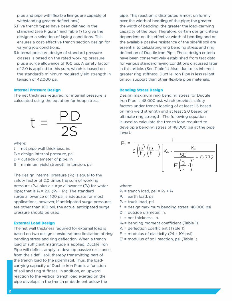
Bending Stress Design
Design maximum ring bending stress for Ductile
Iron Pipe is 48,000 psi, which provides safety
factors under trench loading of at least 1.5 based
on ring yield strength and at least 2.0 based on
ultimate ring strength. The following equation
is used to calculate the trench load required to
develop a bending stress of 48,000 psi at the pipe
invert:
where:
Pv = trench load, psi = Pe + Pt
Pe = earth load, psi
Pt = truck load, psi
f = design maximum bending stress, 48,000 psi
D = outside diameter, in.
t = net thickness, in.
Kb = bending moment coefficient (Table 1)
Kx = deflection coefficient (Table 1)
E = modulus of elasticity (24 x 106 psi)
E’ = modulus of soil reaction, psi (Table 1)
t = PiD2S
-1
Pv =
+ 0.732Kb -
Kx
f
3 D8E
3
E'
tDt
-1Dt

Allowance For Casting Tolerance
Once the minimum manufacturing thickness is
determined, an allowance for casting tolerance
is added to provide the latitude required by
the manufacturing process and to prevent the
possibility of significant minus deviation from design
thickness. Casting allowance is dependent on the
pipe size as shown in the table.
Standard Laying Conditions
As indicated previously, certain factors dependent
on the specified type of laying condition are
essential to the design of Ductile Iron Pipe for
external loads. Two of these factors, the coefficients
for bending (Kb) and deflection (Kx), are dependent
on the width of bedding at the pipe bottom. The
width of bedding is the contact area on the pipe
bottom where bedding support is sufficient to
develop an equal reaction to the vertical trench
load and is commonly referred to as the bedding
angle. The other factor is modulus of soil reaction
(E’), which is a measure of the passive resistance
that can be developed in the sidefill soil. To facilitate
design calculations, these factors have been
conservatively established from reliable test data for
five standard laying conditions (Table 1), thus giving
the design engineer a great deal of flexibility in
selecting the most economical combinations of wall
thickness and bedding and backfill requirements.
Trench Load
The trench load (Pv) used in the design of Ductile
Iron Pipe is expressed as vertical pressure in psi,
and is the sum of earth load (Pe) and truck load (Pt).
Earth load (Pe) is the weight of the unit prism of
soil above the pipe to the ground surface. The
unit weight of the backfill soil is assumed to be
120 lbs./cu. ft., which is conservative for most soils.
In unusual conditions where heavier backfill material
is used, the design earth load should be increased
accordingly.
3
Net Thickness and Service Allowance
A net thickness is computed using both the internal
pressure and bending stress equations as described
above. The larger of the two net thicknesses is then
selected as the net thickness required for internal
pressure and bending stress design. A service
allowance (0.08-inch for all pipe sizes) is then added
to the larger net thickness. This service allowance
provides an additional safety factor for unknowns.
The resulting thickness is the minimum thickness t1.
Deflection Check
Maximum allowable ring deflection for cement-
mortar lined Ductile Iron Pipe is 3 percent of the
outside diameter. Tests have shown that 3 percent
deflection will provide a safety factor of at
least 2.0 with regard to failure of the cement-mortar
lining. Much larger deflections can be sustained
without damage to the pipe wall. The following
equation is used to calculate the trench load
required to develop a ring deflection of 3 percent
of the outside diameter.
where:
t1 = minimum thickness, in. (t + 0.08)
∆x = design deflection, in. (∆x/D = 0.03)
Pv, Kx, E, E’, and D are the same as in the equation
for bending stress.
The t1 required for deflection is compared to the
t1 resulting from internal pressure and bending
stress design. The largest t1 is used and is called the
minimum manufacturing thickness.
∆x/D + 0.732E'8E3
-1Dt1
Pv =12Kx
Size (inches)
3-8
10-12
14-42
48
54-64
Casting Tolerance (inches)
0.05
0.06
0.07
0.08
0.09
Allowances for Casting Tolerance

4
The equation used to compute earth load is as
follows:
where:
Pe = earth load, psi
w = soil weight, 120 lbs./cu. ft.
H = depth of cover, ft.
Truck load (Pt) is based on a single AASHTO H-20
truck on unpaved road or flexible pavement, having
a 16,000 pound wheel load and using a 1.5 impact
factor at all depths. The equation used to compute
truck load is as follows:
where:
Pt = truck load, psi
R = reduction factor which takes into account that
the part of the pipe directly below the wheels is
aided in carrying the truck load by adjacent parts of
the pipe that receive little or no direct load from the
wheels (Table 2)
F = impact factor, 1.5
C = surface load factor calculated for a single
concentrated wheel load centered over an effective
pipe length of 3 ft.
P = wheel load, 16,000 lbs.
b = effective pipe length, 36 in.
D = outside diameter of pipe, in.
The surface load factor, C, is a measure of how
the wheel load at the surface is transmitted and
distributed through the soil to the pipe. The
equation used to calculate the surface load factor
is as follows:
where:
H = depth of cover, ft.
A = outside radius of pipe, ft.
Earth loads (Pe), truck loads (Pt), trench loads
(Pv) and surface load factors (C) computed using
the above equations are listed in ANSI/AWWA
C150/A21.50 for depths of cover ranging from 2.5
feet to 32 feet.
Design Tables
Manual use of the equations for bending stress
and deflection to determine net thickness is
somewhat lengthy and time-consuming. To expedite
calculations, design tables giving diameter-thickness
ratios for a wide range of trench loads have been
developed from these equations for all five standard
laying conditions. With these design tables, a
designer need only know trench load and desired
laying condition to compute net thickness required
for bending stress design and deflection design.
Standard Pressure Classes
Ductile Iron Pipe is manufactured in standard pressure
classes (150-350) which vary in thickness depending
on pipe size. (See Table 3.) Pressure classes are defined
as the standard rated water working pressure of the
pipe in psi. The thickness shown for each pressure
class is thus adequate for the rated water working
pressure plus a surge allowance of 100 psi. Once the
total calculated thickness has been determined for
a particular application, the appropriate standard
pressure class thickness should be selected for
purposes of specifying and ordering. When the
calculated thickness is between two standard
thicknesses, the larger of the two should be selected.
Pe = = =wH144
120H144
H1.2 2C = 1-
(Note: angles are in radians.)
Harcsin
+
π
2π
A2 + H2 + 1.52
(A2 + H2)(1.52 + H2)
1.5AH 1 1+
A2 + H2 + 1.52 A2 + H2 1.52 + H2
Pt = RFCPbD

5
Standard Selection Table
Using the design procedure described, a standard
selection table (Table 4) was developed that
gives maximum depth of cover for each standard
pressure class and laying condition. This table was
provided so that a designer may simply select,
rather than calculate, the appropriate pressure
class and laying condition for a given design
application. For extraordinary design conditions not
shown in the table, such as extremely high internal
pressures or extreme depths of cover, it may be
advisable to consult DIPRA member companies for
recommendations to maximize system design.
Safety Factor
As stated, the safety factor for internal pressure is
2.0 based on minimum yield strength of Ductile Iron
in tension. For external loads, two explicit safety
factors are specified: at least 1.5 based on ring yield
strength and at least 2.0 based on ultimate strength.
Also, the design ring deflection check provides
a safety factor of at least 2.0 based on test data
regarding deflections required to cause failure in
cement-mortar lining.
The above explicit safety factors are used to
establish a design criteria and should not be
confused with the total available safety factor of
Ductile Iron Pipe, which has been shown to be
much greater than the specified safety factors used
in design calculations for the following reasons:
1. The stringent design criteria for Ductile Iron Pipe
are not based on the much greater performance
limits associated with failure of the pipe wall.
2. Specified safety factors are used to calculate
net wall thickness requirements, after which
both service allowance and casting allowance
are added. (For example, the nominal wall
thickness of 30-inch Class 150 Ductile Iron Pipe
is approximately 180 percent of the net wall
thickness required by design.
3. The physical properties of Ductile Iron Pipe will
consistently exceed the minimum values specified
for design.
4. Ductile Iron Pipe can sustain stresses considerably
higher than yield strength determined by standard
test methods without damage to the pipe wall.
5. Design considerations dependent on laying
conditions were established on a conservative
basis.
In the early 1960s, extensive tests were conducted
on Ductile Iron Pipe to determine average values
for tensile strength, ring strength, hardness,
and elongation. Test pipes ranged in size from 2
inches to 24 inches and represented five different
producers. These test results showed the average
bursting tensile strength to be 52,320 psi and the
average ring yield strength to be 84,880 psi for all
pipes tested. These values remain consistent when
compared to test data derived from burst tests
and ring crush tests that have been conducted since
that time. Using these values, an example of total
safety factor with regard to internal pressure design
can be made:
To determine the total safety factor of 6-inch
Pressure Class 350 Ductile Iron Pipe with respect to
internal pressure for 350 psi working pressure and a
standard surge pressure allowance of 100 psi:
1. Compute the hoop stress developed using the
minimum manufacturing thickness:
a. Let Pi = 350 + 100 = 450 psi since total safety
factor is desired.
D = 6.90 in.
b. Nominal thickness of Pressure Class 350 = 0.25 in.
c. Subtract casting tolerance to obtain minimum
thickness manufactured (t1). t1 = 0.25 - 0.05 = 0.20 in.
2. Compare computed hoop stress to average
bursting tensile strength to determine a
representative total safety factor:
S = PiD2t1
S = = 7,762.5 psi(450) (6.90)(2) (0.20)
= 6.7452,320 psi average
7,762.5 psi computed
The total safety factor for internal pressure design
will vary with pipe size, pressure class, and design
working pressure, but the above example serves to
prove that the total available safety factor of Ductile
Iron Pipe is actually much greater than the explicit
design safety factor of 2.0.
With regard to external load design, actual external
loading tests were conducted on large-diameter
Ductile Iron Pipe at Utah State University in the early
1970s to evaluate the C150/A21.50 procedure.
From this test data, which was based on rigorous
conditions, safety factors were calculated by
dividing the loads at cement-mortar lining failure
by allowable loads as well as by dividing the loads
at pipe failure by the allowable loads. Allowable
loads were calculated using the C150/A21.50 design
procedure for external loads. This comparison
showed that when cement-mortar lining failure was
used, the calculated safety factor of the test pipe
averaged 2.98; when pipe failure was used, the
calculated safety factor averaged 5.46.
Using this data as a basis, it is apparent that the
total available safety factor of Ductile Iron Pipe with
respect to external loads is far greater than explicit
design safety factors of 1.5 and 2.0. Further, the
above total available safety factors were determined
on the basis of a separate stress design; for a
combined stress situation (i.e., external load+internal
pressure), the total available safety factor would be
even greater because internal pressure would tend
to reround the pipe, thereby reducing deflection and
ring bending stresses created by external load. It
is therefore evident that the total safety factor for
Ductile Iron Pipe is much more than adequate, and it
is obvious that a thorough analysis of both the pipe
material and the design procedure is necessary
to properly determine actual comparative safety
factors.
Linings
Unless otherwise specified, all Ductile Iron Pipe
installed today is normally furnished with a Portland
cement-mortar lining that conforms to ANSI/AWWA
C104/A21.4. Special linings are also available for
applications where standard cement-mortar linings
are not applicable.
6
Polyethylene Encasement
Ductile Iron Pipe, which is manufactured with a
standard shop coating, needs no external protection
in the majority of installations. There are, however,
highly aggressive soil conditions and/or stray current
conditions where the use of external protection for
the pipe is warranted. In these instances, encasing
the pipe with polyethylene in accordance with the
ANSI/AWWA C105/A21.5 Standard is the generally
recommended method of protection.
In 2013, DIPRA introduced V-Bio®, an enhanced
version of polyethylene encasement. Taking advantage
of co-extrusion technologies for making polyethylene
films, V-Bio® is infused with a corrosion inhibitor and
an anti-microbial to actively prevent the formation of
a corrosion cell under the encasement. V-Bio® adds a
new dimension to the already successful polyethylene
encasement that has protected thousands of miles of
Gray and Ductile Iron Pipe in aggressive soil.
Summary
In the current edition of ANSI/AWWA C150/A21.50,
design criteria are:
• yield strength in tension, 42,000 psi
• ring bending stress, 48,000 psi
• ring deflection, 3 percent
• AASHTO H-20 truck loading at all depths with 1.5
impact factor
• prism earth load for all pipe sizes, and
• five types of laying conditions
Minimum explicit safety factors are set, but
actual total field service safety factors far exceed
these values. Unparalleled field service history,
improvements in manufacturing and quality
control, and research results, including load tests
and its inherent corrosion resistance, have led to
the establishment of the procedures outlined in this
article for the design of Ductile Iron Pipe.

7
Note: DIPRA has developed a computer program to perform these and other design calculations. The program runs online on our website. (www.dipra.org).
FIGURE 1
Standard Laying Conditions for Ductile Iron Pipe
Type 1*
Flat-bottom trench.†
Loose backfill.
Type 3
Pipe bedded in 4-inch
minimum loose
soil.‡ Backfill lightly
consolidated to top
of pipe.
Type 5
Pipe bedded to its centerline in compacted
granular material,** 4-inch minimum under pipe.
Compacted granular or select‡ material to top
of pipe. (Approximately 90% Standard Proctor,
AASHTO T-99.)§
Type 2
Flat-bottom trench.†
Backfill lightly
consolidated to
centerline of pipe.
Type 4
Pipe bedded in sand,
gravel, or crushed
stone to depth of
1/8 pipe diameter,
4-inch minimum.
Backfill compacted to
top of pipe.
(Approximately
80% Standard Proctor,
AASHTO T-99.)§
(See Table 1 for notes.)
LayingCondi-tion†
Type 1*
Type 2
Type 3
Type 4
Type 5
E’psi
150
300
400
500
700
Bedding Angle Degrees
30
45
60
90
150
Kb
0.235
0.210
0.189
0.157
0.128
Kx
0.108
0.105
0.103
0.096
0.085
Description
Flat-bottom trench.†
Loose backfill.
Flat-bottom trench.†
Backfill lightly consolidated
to centerline of pipe.
Pipe bedded in 4-in
minimum loose soil.‡
Backfill lightly consolidated
to top of pipe.
Pipe bedded in sand,
gravel, or crushed stone to
depth of 1/8 pipe diameter,
4-in. minimum. Backfill
compacted to top of pipe.
(Approx. 80 percent
Standard Proctor,
AASHTO T-99.)§
Pipe bedded to its center-
line in compacted granular
material,** 4-in. minimum
under pipe. Compacted
granular or select‡ material
to top of pipe. (Approx. 90
percent Standard Proctor,
AASHTO T-99.)§
TABLE 1
Note: Consideration of the pipe-zone embedment condition included
in this table may be influenced by factors other than pipe strength. For
additional information see ANSI/AWWA C600 “Standard for Installation of
Ductile Iron Mains and Their Appurtenances.”
* For pipe 14 in. and larger, consideration should be given to the use of
laying conditions other than Type 1.
**Granular materials are defined per the AASHTO Soil Classification System
(ASTM D3282) or the United Soil Classification System (ASTM D2487),
with the exception that gravel bedding/backfill adjacent to the pipe is
limited to 2” maximum particle size per ANSI/AWWA C600.
† Flat-bottom is defined as “undisturbed earth.”
‡ Loose soil or select material is defined as “native soil excavated from the
trench, free of rocks, foreign material, and frozen earth.”
§ AASHTO T-99, “Moisture Density Relations of Soils Using a 5.5 pound
Rammer 12-in. Drop.”
Size (inches)
3-121416182024-3036-64
<4
1.000.920.880.850.830.810.80
4-7
1.001.000.950.900.900.850.85
7-10
1.001.001.001.000.950.950.90
>10
1.001.001.001.001.001.001.00
TABLE 2Reduction Factors R for Truck Load Calculations
Depth of Cover – ft.

8
* Calculated thicknesses for these sizes and pressure ratings are less than
those shown above. These are the lowest nominal thicknesses currently
available in these sizes.
Pressure classes are defined as the rated water working pressure of the
pipe in psi. The thicknesses shown are adequate for the rated water
working pressure plus a surge allowance of 100 psi. Calculations are based
on a minimum yield strength in tension of 42,000 psi and 2.0 safety factor
times the sum of working pressure and 100 psi surge allowance.
Thickness can be calculated for rated water working pressure and surges
other than the above by use of the design procedure outlined in this article
and detailed in ANSI/AWWA C150/A21.50.
Ductile Iron Pipe can be utilized for water working pressure greater than
350 psi and is available in thicknesses greater than Pressure Class 350.
Contact DIPRA member companies on specific requirements.
Note: This table is based on a minimum depth of cover of 2.5 feet. For
shallower depths of cover please consult the DIPRA brochure Truck Loads
on Pipe Buried at Shallow Depths.
† Ductile Iron Pipe is adequate for the rated working pressure indicated for
each nominal size plus a surge allowance of 100 psi. Calculations are based
on a 2.0 safety factor times the sum of working pressure and 100 psi surge
allowance. Ductile Iron Pipe for working pressures higher than 350 psi is
available.
‡ An allowance for a single H-20 truck with 1.5 impact factor is included for
all depths of cover.
§ Calculated maximum depth of cover exceeds 100 ft.
*Minimum allowable depth of cover is 3 ft.
†† For pipe 14 in. and larger, consideration should be given to the use of
laying conditions other than Type 1.
Size (inches)
34681012141618202430364248546064
Outside Diameter(inches)
3.964.806.909.0511.1013.2015.3017.4019.5021.6025.8032.0038.3044.5050.8057.5661.6165.67
150
–––––––––––0.340.380.410.460.510.540.56
300
––––––0.300.320.340.360.400.450.510.570.640.720.760.80
250
––––––0.280.300.310.330.370.420.470.520.580.650.680.72
200
––––––––––0.330.380.420.470.520.580.610.64
350
0.25*0.25*0.25*0.25*0.260.280.310.340.360.380.430.490.560.630.700.790.830.87
Pressure Class
Nominal Thickness (inches)
TABLE 3Standard Pressure Classes and
Nominal Thicknesses of Ductile Iron Pipe
Size (inches)
3468101214
16
Pressure†Classpsi
350350350350350350250300350250300350
NominalThickness(inches)
0.250.250.250.250.260.280.280.300.310.300.320.34
Type 1Trench
785326161110††††††††††††
Type 4Trench
100§8547342828232627242628
Type 3Trench
996937251919151719151720
Type 2Trench
886131201515111314111315
Type 5Trench
100§100§65504544364244343944
TABLE 4Rated Working Pressure and
Maximum Depth of Cover
Laying Condition
Maximum Depth of Cover—ft.‡
Size (inches)
18
20
24
30
36
42
48
54
60
64
Pressure†Classpsi
250300350250300350200250300350150200250300350150200250300350150200250300350150200250300350150200250300350150200250300350150200250300350
NominalThickness(inches)
0.310.340.360.330.360.380.330.370.400.430.340.380.420.450.490.380.420.470.510.560.410.470.520.570.630.460.520.580.640.700.510.580.650.720.790.540.610.680.760.830.560.640.720.800.87
Type 1Trench
††††††††††††††††††††††††††††††††††††††††††††††††††††††††††††††††††††††††††††††††††††††††††
Type 4Trench
222628222628172024281416192125141518202413151720231315171922131416192213141619221314161921
Type 3Trench
14171914171912151719912151619912141619912141619911131518911131518911131518911131517
Type 2Trench
10*13151013158*111315—8*111215—8*101215—8101215—8101215—81013155*81013155*8101215
Type 5Trench
313641303538252932372224272933212325283220222527322022242730202224273020222426302021242629
TABLE 4 - continuedRated Working Pressure and
Maximum Depth of Cover
Laying Condition
Maximum Depth of Cover—ft.‡
Strength and Durability for Life®
Ductile Iron Pipe Research Association
An association of quality producers dedicated to the highest pipe standards through a program of continuing research and service to water and wastewater professionals.
P.O. Box 190306 Birmingham, AL 35219 205.402.8700 Telwww.dipra.org
Social Media
Get in the flow with Ductile Iron Pipe by connecting with us on Facebook, Twitter, and LinkedIn.
Visit our website, www.dipra.org/videos, and click on the YouTube icon for informational videos on Ductile Iron Pipe’s ease of use, economic benefits, strength and durability, advantages over PVC, and more.
Copyright © 2016 by Ductile Iron Pipe Research Association
Member Companies
AMERICAN Ductile Iron PipeP.O. Box 2727Birmingham, Alabama 35202-2727
Canada Pipe Company, Ltd.55 Frid St. Unit #1Hamilton, Ontario L8P 4M3 Canada
McWane DuctileP.O. Box 6001Coshocton, Ohio 43812-6001
United States Pipe and Foundry Company Two Chase Corporate DriveSuite 200Birmingham, Alabama 35244
Ductile Iron Pipe is
For more information contact DIPRA or any of its member companies.