Farooque et al. - 2014 - Measuring stem cell dimensionality in tissue scaffolds
Upload
khangminh22Category
view
2download
0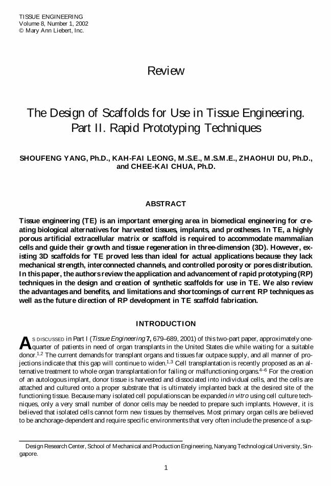
1
TISSUE ENGINEERINGVolume 8, Number 1, 2002© Mary Ann Liebert, Inc.
Review
The Design of Scaffolds for Use in Tissue Engineering.Part II. Rapid Prototyping Techniques
SHOUFENG YANG, Ph.D., KAH-FAI LEONG, M.S.E., M.S.M.E., ZHAOHUI DU, Ph.D.,and CHEE-KAI CHUA, Ph.D.
ABSTRACT
Tissue engineering (TE) is an important emerging area in biomedical engineering for cre-ating biological alternatives for harvested tissues, implants, and prostheses. In TE, a highlyporous artificial extracellular matrix or scaffold is required to accommodate mammaliancells and guide their growth and tissue regeneration in three-dimension (3D). However, ex-isting 3D scaffolds for TE proved less than ideal for actual applications because they lackmechanical strength, interconnected channels, and controlled porosity or pores distribution.In this paper, the authors review the application and advancement of rapid prototyping (RP)techniques in the design and creation of synthetic scaffolds for use in TE. We also reviewthe advantages and benefits, and limitations and shortcomings of current RP techniques aswell as the future direction of RP development in TE scaffold fabrication.
INTRODUCTION
AS DISCUSSED in Part I (Tissue Engineering 7, 679–689, 2001) of this two-part paper, approximately one-quarter of patients in need of organ transplants in the United States die while waiting for a suitable
donor.1,2 The current demands for transplant organs and tissues far outpace supply, and all manner of pro-jections indicate that this gap will continue to widen.1,3 Cell transplantation is recently proposed as an al-ternative treatment to whole organ transplantation for failing or malfunctioning organs.4–6 For the creationof an autologous implant, donor tissue is harvested and dissociated into individual cells, and the cells areattached and cultured onto a proper substrate that is ultimately implanted back at the desired site of thefunctioning tissue. Because many isolated cell populations can be expanded in vitro using cell culture tech-niques, only a very small number of donor cells may be needed to prepare such implants. However, it isbelieved that isolated cells cannot form new tissues by themselves. Most primary organ cells are believedto be anchorage-dependent and require specific environments that very often include the presence of a sup-
Design Research Center, School of Mechanical and Production Engineering, Nanyang Technological University, Sin-gapore.
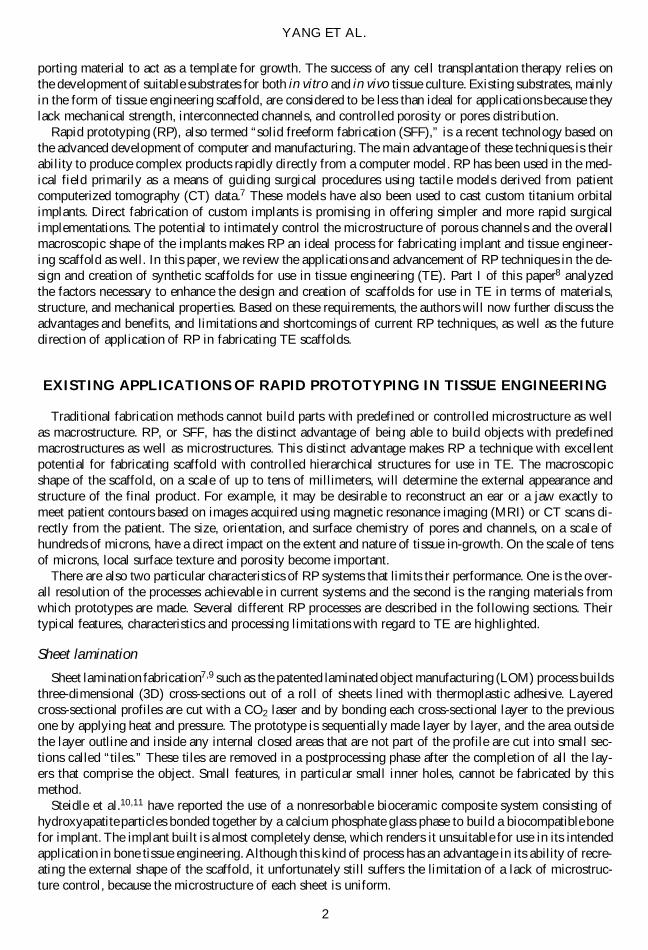
porting material to act as a template for growth. The success of any cell transplantation therapy relies onthe development of suitable substrates for both in vitro and in vivo tissue culture. Existing substrates, mainlyin the form of tissue engineering scaffold, are considered to be less than ideal for applications because theylack mechanical strength, interconnected channels, and controlled porosity or pores distribution.
Rapid prototyping (RP), also termed “solid freeform fabrication (SFF),” is a recent technology based onthe advanced development of computer and manufacturing. The main advantage of these techniques is theirability to produce complex products rapidly directly from a computer model. RP has been used in the med-ical field primarily as a means of guiding surgical procedures using tactile models derived from patientcomputerized tomography (CT) data.7 These models have also been used to cast custom titanium orbitalimplants. Direct fabrication of custom implants is promising in offering simpler and more rapid surgicalimplementations. The potential to intimately control the microstructure of porous channels and the overallmacroscopic shape of the implants makes RP an ideal process for fabricating implant and tissue engineer-ing scaffold as well. In this paper, we review the applications and advancement of RP techniques in the de-sign and creation of synthetic scaffolds for use in tissue engineering (TE). Part I of this paper8 analyzedthe factors necessary to enhance the design and creation of scaffolds for use in TE in terms of materials,structure, and mechanical properties. Based on these requirements, the authors will now further discuss theadvantages and benefits, and limitations and shortcomings of current RP techniques, as well as the futuredirection of application of RP in fabricating TE scaffolds.
EXISTING APPLICATIONS OF RAPID PROTOTYPING IN TISSUE ENGINEERING
Traditional fabrication methods cannot build parts with predefined or controlled microstructure as wellas macrostructure. RP, or SFF, has the distinct advantage of being able to build objects with predefinedmacrostructures as well as microstructures. This distinct advantage makes RP a technique with excellentpotential for fabricating scaffold with controlled hierarchical structures for use in TE. The macroscopicshape of the scaffold, on a scale of up to tens of millimeters, will determine the external appearance andstructure of the final product. For example, it may be desirable to reconstruct an ear or a jaw exactly tomeet patient contours based on images acquired using magnetic resonance imaging (MRI) or CT scans di-rectly from the patient. The size, orientation, and surface chemistry of pores and channels, on a scale ofhundreds of microns, have a direct impact on the extent and nature of tissue in-growth. On the scale of tensof microns, local surface texture and porosity become important.
There are also two particular characteristics of RP systems that limits their performance. One is the over-all resolution of the processes achievable in current systems and the second is the ranging materials fromwhich prototypes are made. Several different RP processes are described in the following sections. Theirtypical features, characteristics and processing limitations with regard to TE are highlighted.
Sheet lamination
Sheet lamination fabrication7,9 such as the patented laminated object manufacturing (LOM) process buildsthree-dimensional (3D) cross-sections out of a roll of sheets lined with thermoplastic adhesive. Layeredcross-sectional profiles are cut with a CO2 laser and by bonding each cross-sectional layer to the previousone by applying heat and pressure. The prototype is sequentially made layer by layer, and the area outsidethe layer outline and inside any internal closed areas that are not part of the profile are cut into small sec-tions called “tiles.” These tiles are removed in a postprocessing phase after the completion of all the lay-ers that comprise the object. Small features, in particular small inner holes, cannot be fabricated by thismethod.
Steidle et al.10,11 have reported the use of a nonresorbable bioceramic composite system consisting ofhydroxyapatite particles bonded together by a calcium phosphate glass phase to build a biocompatible bonefor implant. The implant built is almost completely dense, which renders it unsuitable for use in its intendedapplication in bone tissue engineering. Although this kind of process has an advantage in its ability of recre-ating the external shape of the scaffold, it unfortunately still suffers the limitation of a lack of microstruc-ture control, because the microstructure of each sheet is uniform.
YANG ET AL.
2
Adhesion bonding
In this method, 3D parts are created by a layered printing process with adhesive bonding, using powderas the base material, according to sliced cross-sectional computer-assisted design (CAD) data of the object.Each layer of powder is selectively joined where the part is to be formed by ink-jet printing of a bindermaterial. The process is repeated layer by layer until the part is complete. An example of such technologyis three-dimensional printing (3DP).
Cima et al.12,13 demonstrated using 3DP to build drug delivery devices and tissue regeneration devices.Although only polyethylene oxide (PEO) and polycaprolactone (PCL) powders were used in those experi-ments, theoretically and virtually any materials that can be processed into powdered form can be used for3D printing.13 TheriForm™,14 one of six licensees of 3DP, developed pharmaceutical dosage forms andmedical products, including drug delivery and TE, based on 3DP fabrication process. Cima15 produced 200-mm lines by printing polymer solutions rather than using pure solvent, while the later will produce a lineprimitive of 500 mm in width.
In this method, adapting a appropriate binder for the different materials used can pose problems for bio-medical applications. Some organic solvents that are in use now as binders, such as chloroform and meth-ylene chloride, are harmful to the human body and are difficult to remove completely. Even after 1 week,during which samples of implants are placed in a vacuum to remove excess solvent, the amount of chlo-roform managed only to be reduced from 10wt% to 0.5wt%.16 Another difficulty is that excess powder thatis trapped in small channels is difficult to remove. Also, channels of less than 1 mm in diameter have notbeen successfully built.
Laser sintering
In laser sintering methods, parts are built by sintering of powder on a powder bed, when an infrared laserbeam hits a thin layer of powdered material such as wax, polycarbonate, nylon, or even metal. The inter-action of the laser beam with the powder raises the local surface temperature to the glass transition tem-perature of the powder. This is just below the melting temperature. It results in particle bonding—fusingthe particles onto each other and to the previous layer to form a solid. Limited by the power of the laserand thermal diffusion, the glass transition temperature and melting point of the powder cannot be too high.For ceramic powder, the polymer–ceramic mixture is always used, in which case the polymer is used as alow melting point binder.
Lee et al.17,18 coated calcium phosphate powder with polymer by spray drying slurry of particulate andemulsion binder. The coated powder was sintered by selective laser sintering (SLS) to fabricate artificialcalcium phosphate bone implant. Postprocessing included infiltrating the sintered part with calcium phos-phate solution or phosphoric acid–based inorganic cement. This was used to improve the density of greenpart to prevented collapse in the subsequently polymer binder burn out stage. However, the compressivestrengths19 of the infiltrated sintered part without macropores was only 36.0 6 7.5 MPa. Implant modelwith macropores of about 2 mm in diameter was built for preclinical trials to assess the biocompatibility.It is believed that macropores in the implant should be smaller to increase the surface area for cell attach-ment and to improve the mechanical strength for load-bearing requirements.
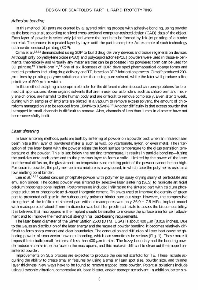
The laser beam diameter of the Sinter Station 2500 (DTM, USA) is about 400 mm (0.016 inches). Dueto the Gaussian distribution of the laser energy and the nature of powder bonding, it becomes relatively dif-ficult to form sharp corners and clear boundaries. The conduction and diffusion of laser heat cause neigh-boring powder of scan vector unwanted bonding, which can sometimes be serious (Fig. 1). These make itimpossible to build small features of less than 400 mm in size. The fuzzy boundary and the bonding pow-der induce a coarse inner surface on the macropores, and this makes it difficult to clean out the trapped un-sintered powder.
Improvements on SLS process are expected to produce the desired scaffold for TE. These include ac-quiring the ability to create smaller features by using a smaller laser spot size, powder size, and thinnerlayer thickness. New ways have to be found to remove trapped loose powder. Potential solutions includeusing ultrasonic vibration, compressive air, bead blaster, and/or appropriate solvent. In addition, better sin-
DESIGN OF SCAFFOLDS. PART II. RAPID PROTOTYPING
3
tering environment is necessary so that the humidity, inertness of surrounding atmosphere, and vacuum canbe controlled within a smaller working chamber.
Photopolymerization
The principle of this method is based on the polymerization of photopolymer resins that is initiated byradiant energy from electromagnetic radiation.7 Photopolymer resins are mixtures of simple low-molecu-lar-weight monomers capable of chain-reacting to form solid long-chain polymers when activated by radi-ant energy within specific wavelength range. There are two basic types of liquid-based commercial RP ma-chines that use photopolymerization. One uses a laser, while the other uses a masked lamp to cure thephotopolymers.7,9 In the first system, a deflected laser beam is used to irradiate a thin polymer layer at thesurface of a vat filled with liquid photopolymer resin. The irradiated areas of photopolymer react chemi-cally to become solid. For example, 3D system’s stereolithography apparatus (SLA) uses an ultraviolet laserto solidify an epoxy resin. The second system uses masked illumination, instead of a point-by-point methodused by laser system. It irradiates a complete layer of polymer every single time. An example of this maskedlamp technique is Cubital’s solid ground curing (SGC). Rapid micro product development (RMPD),20 a mi-crostereolithography method developed by MicroTEC, and mentioned by Chua et al.,9 is a promising RPapproach. This technology, based on combination of masked lamp technology and laser curing photopoly-merization, emerged in the middle of 1999.
Langton et al.21 described a method for the development of a user-defined structural model simulatingcancellous bone of the human calcaneus using SLA. The potential for SLA-produced samples to be usedas a structurally controlled cancellous bone mimic was investigated by producing a 3D rod lattice of 3 mmcenter-to-center distance and rod diameters of 1 mm (70% porosity) representing healthy bone and 0.4 mm(95% porosity) representing osteoporotic bone.
Chu et al.22 built hydroxyapatite prototypes for bone tissue scaffolds from Image-Based Design files, fea-turing an interior architecture of void passages. Direct ceramic SLA22 is done using UV-curable suspen-sions of ceramic powders in acrylates in a conventional SLA machine. Viscosity control for these highlyconcentrated suspensions and cure depth behavior are the main issues for fabricating a ceramic part withthe stereolithography techniques.
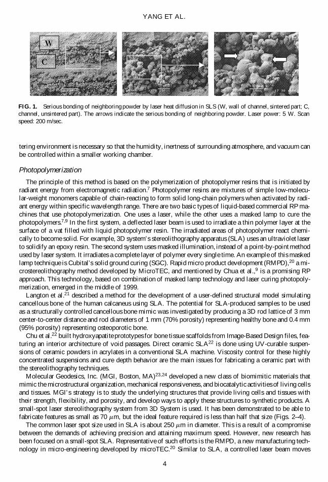
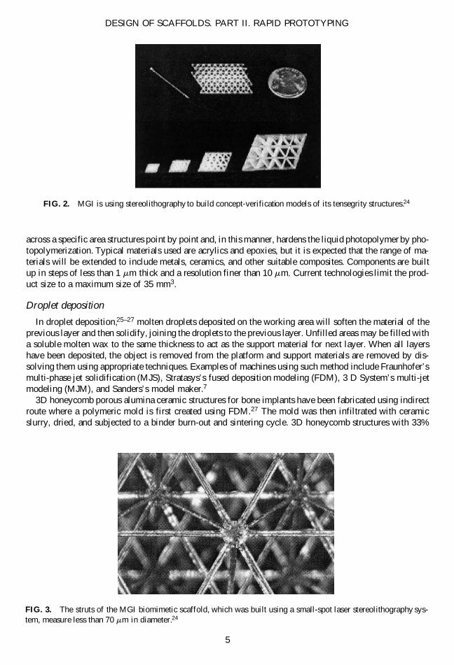
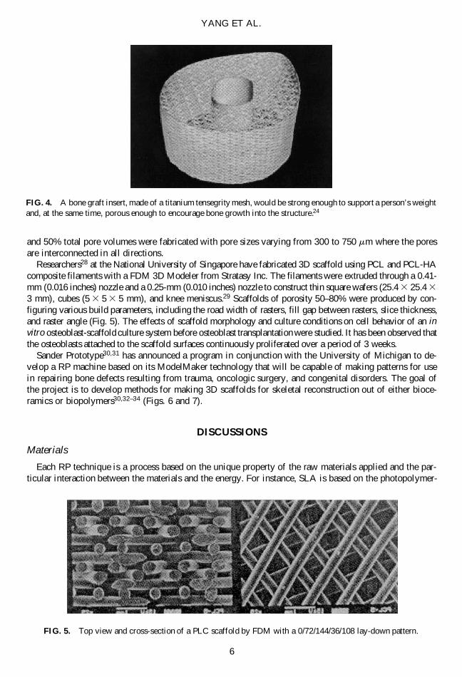
Molecular Geodesics, Inc. (MGI, Boston, MA)23,24 developed a new class of biomimitic materials thatmimic the microstructural organization, mechanical responsiveness, and biocatalytic activities of living cellsand tissues. MGI’s strategy is to study the underlying structures that provide living cells and tissues withtheir strength, flexibility, and porosity, and develop ways to apply these structures to synthetic products. Asmall-spot laser stereolithography system from 3D System is used. It has been demonstrated to be able tofabricate features as small as 70 mm, but the ideal feature required is less than half that size (Figs. 2–4).
The common laser spot size used in SLA is about 250 mm in diameter. This is a result of a compromisebetween the demands of achieving precision and attaining maximum speed. However, new research hasbeen focused on a small-spot SLA. Representative of such efforts is the RMPD, a new manufacturing tech-nology in micro-engineering developed by microTEC.20 Similar to SLA, a controlled laser beam moves
YANG ET AL.
4
FIG. 1. Serious bonding of neighboring powder by laser heat diffusion in SLS (W, wall of channel, sintered part; C,channel, unsintered part). The arrows indicate the serious bonding of neighboring powder. Laser power: 5 W. Scanspeed: 200 m/sec.
across a specific area structures point by point and, in this manner, hardens the liquid photopolymer by pho-topolymerization. Typical materials used are acrylics and epoxies, but it is expected that the range of ma-terials will be extended to include metals, ceramics, and other suitable composites. Components are builtup in steps of less than 1 mm thick and a resolution finer than 10 mm. Current technologies limit the prod-uct size to a maximum size of 35 mm3.
Droplet deposition
In droplet deposition,25–27 molten droplets deposited on the working area will soften the material of theprevious layer and then solidify, joining the droplets to the previous layer. Unfilled areas may be filled witha soluble molten wax to the same thickness to act as the support material for next layer. When all layershave been deposited, the object is removed from the platform and support materials are removed by dis-solving them using appropriate techniques. Examples of machines using such method include Fraunhofer’smulti-phase jet solidification (MJS), Stratasys’s fused deposition modeling (FDM), 3 D System’s multi-jetmodeling (MJM), and Sanders’s model maker.7
3D honeycomb porous alumina ceramic structures for bone implants have been fabricated using indirectroute where a polymeric mold is first created using FDM.27 The mold was then infiltrated with ceramicslurry, dried, and subjected to a binder burn-out and sintering cycle. 3D honeycomb structures with 33%
DESIGN OF SCAFFOLDS. PART II. RAPID PROTOTYPING
5
FIG. 2. MGI is using stereolithography to build concept-verification models of its tensegrity structures.24
FIG. 3. The struts of the MGI biomimetic scaffold, which was built using a small-spot laser stereolithography sys-tem, measure less than 70 mm in diameter.24
and 50% total pore volumes were fabricated with pore sizes varying from 300 to 750 mm where the poresare interconnected in all directions.
Researchers28 at the National University of Singapore have fabricated 3D scaffold using PCL and PCL-HAcomposite filaments with a FDM 3D Modeler from Stratasy Inc. The filaments were extruded through a 0.41-mm (0.016 inches) nozzle and a 0.25-mm (0.010 inches) nozzle to construct thin square wafers (25.4 3 25.4 3
3 mm), cubes (5 3 5 3 5 mm), and knee meniscus.29 Scaffolds of porosity 50–80% were produced by con-figuring various build parameters, including the road width of rasters, fill gap between rasters, slice thickness,and raster angle (Fig. 5). The effects of scaffold morphology and culture conditions on cell behavior of an invitro osteoblast-scaffold culture system before osteoblast transplantation were studied. It has been observed thatthe osteoblasts attached to the scaffold surfaces continuously proliferated over a period of 3 weeks.
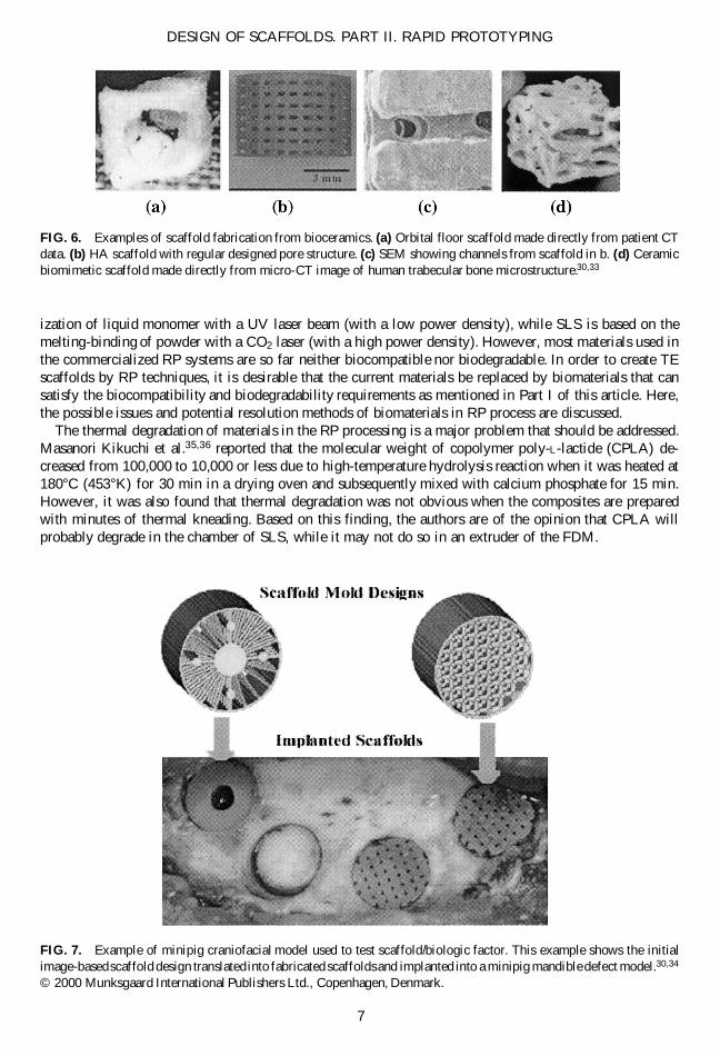
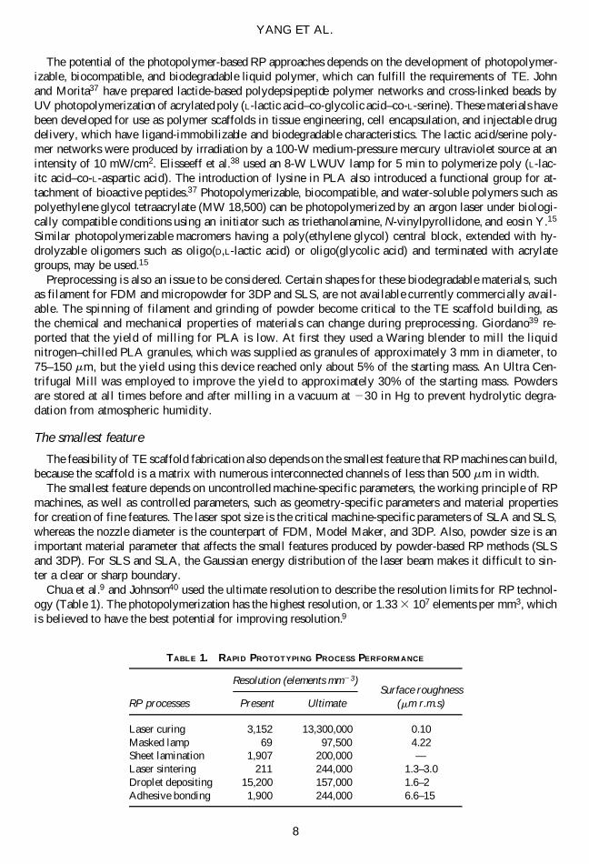
Sander Prototype30,31 has announced a program in conjunction with the University of Michigan to de-velop a RP machine based on its ModelMaker technology that will be capable of making patterns for usein repairing bone defects resulting from trauma, oncologic surgery, and congenital disorders. The goal ofthe project is to develop methods for making 3D scaffolds for skeletal reconstruction out of either bioce-ramics or biopolymers30,32–34 (Figs. 6 and 7).
DISCUSSIONS
Materials
Each RP technique is a process based on the unique property of the raw materials applied and the par-ticular interaction between the materials and the energy. For instance, SLA is based on the photopolymer-
YANG ET AL.
6
FIG. 4. A bone graft insert, made of a titanium tensegrity mesh, would be strong enough to support a person’s weightand, at the same time, porous enough to encourage bone growth into the structure.24
FIG. 5. Top view and cross-section of a PLC scaffold by FDM with a 0/72/144/36/108 lay-down pattern.
ization of liquid monomer with a UV laser beam (with a low power density), while SLS is based on themelting-binding of powder with a CO2 laser (with a high power density). However, most materials used inthe commercialized RP systems are so far neither biocompatible nor biodegradable. In order to create TEscaffolds by RP techniques, it is desirable that the current materials be replaced by biomaterials that cansatisfy the biocompatibility and biodegradability requirements as mentioned in Part I of this article. Here,the possible issues and potential resolution methods of biomaterials in RP process are discussed.
The thermal degradation of materials in the RP processing is a major problem that should be addressed.Masanori Kikuchi et al.35,36 reported that the molecular weight of copolymer poly-L-lactide (CPLA) de-creased from 100,000 to 10,000 or less due to high-temperature hydrolysis reaction when it was heated at180°C (453°K) for 30 min in a drying oven and subsequently mixed with calcium phosphate for 15 min.However, it was also found that thermal degradation was not obvious when the composites are preparedwith minutes of thermal kneading. Based on this finding, the authors are of the opinion that CPLA willprobably degrade in the chamber of SLS, while it may not do so in an extruder of the FDM.
DESIGN OF SCAFFOLDS. PART II. RAPID PROTOTYPING
7
FIG. 6. Examples of scaffold fabrication from bioceramics. (a) Orbital floor scaffold made directly from patient CTdata. (b) HA scaffold with regular designed pore structure. (c) SEM showing channels from scaffold in b. (d) Ceramicbiomimetic scaffold made directly from micro-CT image of human trabecular bone microstructure.30,33
FIG. 7. Example of minipig craniofacial model used to test scaffold/biologic factor. This example shows the initialimage-based scaffold design translated into fabricated scaffolds and implanted into a minipig mandible defect model.30,34
© 2000 Munksgaard International Publishers Ltd., Copenhagen, Denmark.
The potential of the photopolymer-based RP approaches depends on the development of photopolymer-izable, biocompatible, and biodegradable liquid polymer, which can fulfill the requirements of TE. Johnand Morita37 have prepared lactide-based polydepsipeptide polymer networks and cross-linked beads byUV photopolymerization of acrylated poly (L-lactic acid–co-glycolic acid–co-L-serine). These materials havebeen developed for use as polymer scaffolds in tissue engineering, cell encapsulation, and injectable drugdelivery, which have ligand-immobilizable and biodegradable characteristics. The lactic acid/serine poly-mer networks were produced by irradiation by a 100-W medium-pressure mercury ultraviolet source at anintensity of 10 mW/cm2. Elisseeff et al.38 used an 8-W LWUV lamp for 5 min to polymerize poly (L-lac-itc acid–co-L-aspartic acid). The introduction of lysine in PLA also introduced a functional group for at-tachment of bioactive peptides.37 Photopolymerizable, biocompatible, and water-soluble polymers such aspolyethylene glycol tetraacrylate (MW 18,500) can be photopolymerized by an argon laser under biologi-cally compatible conditions using an initiator such as triethanolamine, N-vinylpyrollidone, and eosin Y.15
Similar photopolymerizable macromers having a poly(ethylene glycol) central block, extended with hy-drolyzable oligomers such as oligo(D,L-lactic acid) or oligo(glycolic acid) and terminated with acrylategroups, may be used.15
Preprocessing is also an issue to be considered. Certain shapes for these biodegradable materials, suchas filament for FDM and micropowder for 3DP and SLS, are not available currently commercially avail-able. The spinning of filament and grinding of powder become critical to the TE scaffold building, asthe chemical and mechanical properties of materials can change during preprocessing. Giordano39 re-ported that the yield of milling for PLA is low. At first they used a Waring blender to mill the liquidnitrogen–chilled PLA granules, which was supplied as granules of approximately 3 mm in diameter, to75–150 mm, but the yield using this device reached only about 5% of the starting mass. An Ultra Cen-trifugal Mill was employed to improve the yield to approximately 30% of the starting mass. Powdersare stored at all times before and after milling in a vacuum at 230 in Hg to prevent hydrolytic degra-dation from atmospheric humidity.
The smallest feature
The feasibility of TE scaffold fabrication also depends on the smallest feature that RP machines can build,because the scaffold is a matrix with numerous interconnected channels of less than 500 mm in width.
The smallest feature depends on uncontrolled machine-specific parameters, the working principle of RPmachines, as well as controlled parameters, such as geometry-specific parameters and material propertiesfor creation of fine features. The laser spot size is the critical machine-specific parameters of SLA and SLS,whereas the nozzle diameter is the counterpart of FDM, Model Maker, and 3DP. Also, powder size is animportant material parameter that affects the small features produced by powder-based RP methods (SLSand 3DP). For SLS and SLA, the Gaussian energy distribution of the laser beam makes it difficult to sin-ter a clear or sharp boundary.
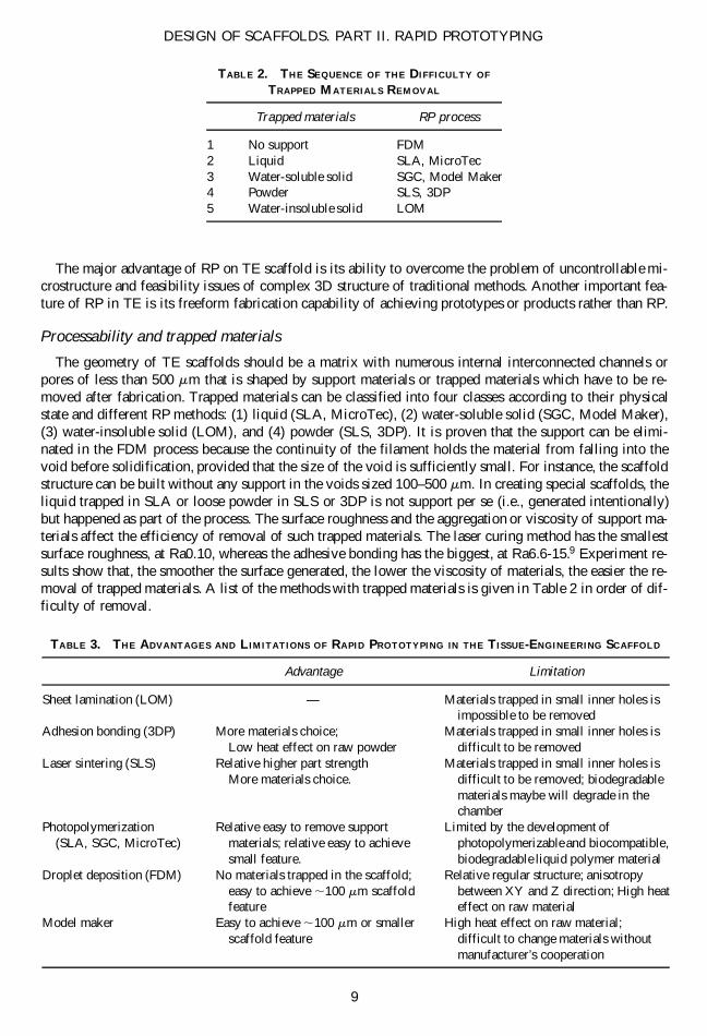
Chua et al.9 and Johnson40 used the ultimate resolution to describe the resolution limits for RP technol-ogy (Table 1). The photopolymerization has the highest resolution, or 1.33 3 107 elements per mm3, whichis believed to have the best potential for improving resolution.9
YANG ET AL.
8
TABLE 1. RAPID PROTOTYPING PROCESS PERFORMANCE
Resolution (elements mm23)Surface roughness
RP processes Present Ultimate (mm r.m.s)
Laser curing 3,152 13,300,000 0.10Masked lamp 69 97,500 4.22Sheet lamination 1,907 200,000 —Laser sintering 211 244,000 1.3–3.0Droplet depositing 15,200 157,000 1.6–2.0Adhesive bonding 1,900 244,000 6.6–15.
The major advantage of RP on TE scaffold is its ability to overcome the problem of uncontrollable mi-crostructure and feasibility issues of complex 3D structure of traditional methods. Another important fea-ture of RP in TE is its freeform fabrication capability of achieving prototypes or products rather than RP.
Processability and trapped materials
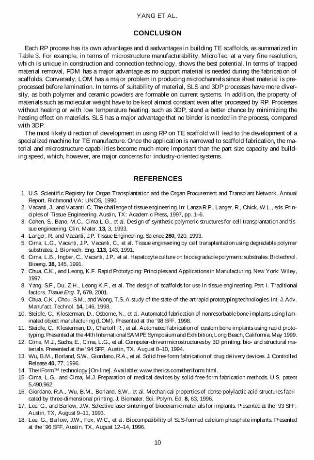
The geometry of TE scaffolds should be a matrix with numerous internal interconnected channels orpores of less than 500 mm that is shaped by support materials or trapped materials which have to be re-moved after fabrication. Trapped materials can be classified into four classes according to their physicalstate and different RP methods: (1) liquid (SLA, MicroTec), (2) water-soluble solid (SGC, Model Maker),(3) water-insoluble solid (LOM), and (4) powder (SLS, 3DP). It is proven that the support can be elimi-nated in the FDM process because the continuity of the filament holds the material from falling into thevoid before solidification, provided that the size of the void is sufficiently small. For instance, the scaffoldstructure can be built without any support in the voids sized 100–500 mm. In creating special scaffolds, theliquid trapped in SLA or loose powder in SLS or 3DP is not support per se (i.e., generated intentionally)but happened as part of the process. The surface roughness and the aggregation or viscosity of support ma-terials affect the efficiency of removal of such trapped materials. The laser curing method has the smallestsurface roughness, at Ra0.10, whereas the adhesive bonding has the biggest, at Ra6.6-15.9 Experiment re-sults show that, the smoother the surface generated, the lower the viscosity of materials, the easier the re-moval of trapped materials. A list of the methods with trapped materials is given in Table 2 in order of dif-ficulty of removal.
DESIGN OF SCAFFOLDS. PART II. RAPID PROTOTYPING
9
TABLE 2. THE SEQUENCE OF THE DIFFICULTY OF
TRAPPED MATERIALS REMOVAL
Trapped materials RP process
1 No support FDM2 Liquid SLA, MicroTec3 Water-soluble solid SGC, Model Maker4 Powder SLS, 3DP5 Water-insoluble solid LOM
TABLE 3. THE ADVANTAGES AND LIMITATIONS OF RAPID PROTOTYPING IN THE TISSUE-ENGINEERING SCAFFOLD
Advantage Limitation
Sheet lamination (LOM) — Materials trapped in small inner holes isimpossible to be removed
Adhesion bonding (3DP) More materials choice; Materials trapped in small inner holes isLow heat effect on raw powder difficult to be removed
Laser sintering (SLS) Relative higher part strength Materials trapped in small inner holes isMore materials choice. difficult to be removed; biodegradable
materials maybe will degrade in thechamber
Photopolymerization Relative easy to remove support Limited by the development of(SLA, SGC, MicroTec) materials; relative easy to achieve photopolymerizable and biocompatible,
small feature. biodegradable liquid polymer materialDroplet deposition (FDM) No materials trapped in the scaffold; Relative regular structure; anisotropy
easy to achieve ,100 mm scaffold between XY and Z direction; High heatfeature effect on raw material
Model maker Easy to achieve ,100 mm or smaller High heat effect on raw material;scaffold feature difficult to change materials without
manufacturer’s cooperation
CONCLUSION
Each RP process has its own advantages and disadvantages in building TE scaffolds, as summarized inTable 3. For example, in terms of microstructure manufacturability, MicroTec, at a very fine resolution,which is unique in construction and connection technology, shows the best potential. In terms of trappedmaterial removal, FDM has a major advantage as no support material is needed during the fabrication ofscaffolds. Conversely, LOM has a major problem in producing microchannels since sheet material is pre-processed before lamination. In terms of suitability of material, SLS and 3DP processes have more diver-sity, as both polymer and ceramic powders are formable on current systems. In addition, the property ofmaterials such as molecular weight have to be kept almost constant even after processed by RP. Processeswithout heating or with low temperature heating, such as 3DP, stand a better chance by minimizing theheating effect on materials. SLS has a major advantage that no binder is needed in the process, comparedwith 3DP.
The most likely direction of development in using RP on TE scaffold will lead to the development of aspecialized machine for TE manufacture. Once the application is narrowed to scaffold fabrication, the ma-terial and microstructure capabilities become much more important than the part size capacity and build-ing speed, which, however, are major concerns for industry-oriented systems.
REFERENCES
1. U.S. Scientific Registry for Organ Transplantation and the Organ Procurement and Transplant Network. AnnualReport. Richmond VA: UNOS, 1990.
2. Vacanti, J., and Vacanti, C. The challenge of tissue engineering. In: Lanza R.P., Langer, R., Chick, W.L., eds. Prin-ciples of Tissue Engineering. Austin, TX: Academic Press, 1997, pp. 1–6.
3. Cohen, S., Bano, M.C., Cima L.G., et al. Design of synthetic polymeric structures for cell transplantation and tis-sue engineering. Clin. Mater. 13, 3, 1993.
4. Langer, R. and Vacanti, J.P. Tissue Engineering. Science 260, 920, 1993.5. Cima, L.G., Vacanti, J.P., Vacanti, C., et al. Tissue engineering by cell transplantation using degradable polymer
substrates. J. Biomech. Eng. 113, 143, 1991.6. Cima, L.B., Ingber, C., Vacanti, J.P., et al. Hepatocyte culture on biodegradable polymeric substrates. Biotechnol.
Bioeng. 38, 145, 1991.7. Chua, C.K., and Leong, K.F. Rapid Prototyping: Principles and Applications in Manufacturing. New York: Wiley,
1997.8. Yang, S.F., Du, Z.H., Leong K.F., et al. The design of scaffolds for use in tissue engineering. Part I. Traditional
factors. Tissue Eng. 7, 679, 2001.9. Chua, C.K., Chou, S.M., and Wong, T.S. A study of the state-of-the-art rapid prototyping technologies. Int. J. Adv.
Manufact. Technol. 14, 146, 1998.10. Steidle, C., Klosterman, D., Osborne, N., et al. Automated fabrication of nonresorbable bone implants using lam-
inated object manufacturing (LOM). Presented at the ’98 SFF, 1998.11. Steidle, C., Klosterman, D., Chartoff R., et al. Automated fabrication of custom bone implants using rapid proto-
typing. Presented at the 44th International SAMPE Symposium and Exhibition, Long Beach, California, May 1999.12. Cima, M.J., Sachs, E., Cima, L.G., et al. Computer-driven microstructures by 3D printing: bio- and structural ma-
terials. Presented at the ’94 SFF, Austin, TX, August 8–10, 1994.13. Wu, B.M., Borland, S.W., Giordano, R.A., et al. Solid free form fabrication of drug delivery devices. J. Controlled
Release 40, 77, 1996.14. TheriForm™ technology [On-line]. Available: www.therics.com/theriform.html.15. Cima, L.G., and Cima, M.J. Preparation of medical devices by solid free-form fabrication methods. U.S. patent
5,490,962.16. Giordano, R.A., Wu, B.M., Borland, S.W., et al. Mechanical properties of dense polylactic acid structures fabri-
cated by three-dimensional printing. J. Biomater. Sci. Polym. Ed. 8, 63, 1996.17. Lee, G., and Barlow, J.W. Selective laser sintering of bioceramic materials for implants. Presented at the ’93 SFF,
Austin, TX, August 9–11, 1993.18. Lee, G., Barlow, J.W., Fox, W.C., et al. Biocompatibility of SLS-formed calcium phosphate implants. Presented
at the ’96 SFF, Austin, TX, August 12–14, 1996.
YANG ET AL.
10
19. Vail, N.K., Swain, L.D., Fox, W.C., et al. Materials for biomedical applications. Presented at the ’98 SFF, Austin,TX, August 10–12, 1998.
20. Gesellschaft für Mikrotechnologie mbH. Microsystems production with rapid micro product development (RMPD)[On-line]. Available: www. microtec-d.com/engl.htm.
21. Langton, C.M., Whitehead, M.A., Langton, D.K., et al. Development of a cancellous bone structural model bystereolithography for ultrasound characterisation of the calcaneus. Med. Eng. Phys. 19, 599, 1997.
22. Chu, G.T.-M., Brady, G.A., Miao, W., et al. Ceramic SFF by direct and indirect stereolithography. Presented atMaterials Research Society, Fall Meeting, November 30–December 3, 1999, Boston, MA, pp. 119–123.
23. Rapid prototyping helps duplicate the structure of life. Rapid Prototyping Rep. 9, 1, 1999.24. Molecular Geodesics, Inc. Innovation through biological mimicry [On-line]. Available: www.molecgeodesics.
com/contactUs.html.25. Pekin, S., Koehl, D., and Zangvil, A. A new HAPEX-like biocomposite that can be shaped by fused deposition of
materials (FDM). Presented at the ’99 SFF, Austin, TX, August 9–11, 1999.26. Pekin, S., and Zangvil, A. Effect of powder characteristics on the sintering of hydroxyapatite feedstocks that can
be shaped by FDM. Presented at the ’99 SFF, Austin, TX, August 9–11, 1999.27. Bose, S., Avila, M., and Bandyopadhyay, A. Processing of bioceramic implants via fused deposition process. Pre-
sented at the ’98 SFF, Austin, TX, August 10–12, 1998.28. Zein, I., Hutmacher, D.W., Schantz, J.T., et al. Processing of 3D scaffolds by fused deposition modeling. Presented
at the International Workshop on Advances in Materials Science and Technology, Singapore, April 2000.29. Schantz, J.T., Hutmacher, D.W., Zein, I., et al. A study of human osteoblasts on poly(caprolactone)-scaffolds. Pre-
sented at the International Workshop on Advances in Materials Science and Technology, Singapore, April 2000.30. Hollister, S.J. University of Michigan White Paper BRP proposal: systems integration for skeletal engineering. [On-
line]. Available. www.bme.umich.edu/skelegen/.31. Sanders Prototype. Development opportunities: Sanders seeking partners for medical ModelMaker. Rapid Proto-
typing Rep. 9, 7, 1999.32. Hollister, S.J., Levy, R.A., Chu, T.-M.G., et al. Design and manufacture of an orbital floor scaffold using image
processing and rapid prototyping. Presented at the American Society of Mechanical Engineers (ASME) Bioengi-neering Conference, New York, 1997.
33. Levy, R.A., Chu, T.M.G., Halloran, J.W., et al. CT-generated porous Hydroxyapatite orbital floor prothesis as aprototype bioimplant. Am. J. Neuroradiol. 18, 1522, 1997.
34. Hollister, S.J., Chu, T.M., Levy, R.A., et al. An image-based approach to designing and manufacturing craniofa-cial scaffolds. Int. J. Oral Maxillofac. Surg. 29, 67, 2000.
35. Kikuchi, M., Cho, S., Tanaka, J., et al. Preparation and biocompatibility of ab-tricalcium-phosphate/copolymer-ized-poly-L-lactide composite. J Jpn Soc Powder Metallurgy 45, 36, 1999.
36. Kikuchi, M., Suecsugu, Y., Tanaka, J., et al. Preparation and mechanical properties of calcium phosphate/copoly-L-lactide composite. J. Mater. Sci. 8, 361, 1997.
37. John, G., and Morita, M. Synthesis and characterization of photo-cross-linked networks based on L-lactide/serinecopolymers. Macromolecules 32, 1853, 1999.
38. Elisseeff, J., Anseth, K., Langer, R., et al. Synthesis and characterization of photo-cross-linked polymers based onpoly(L-lacitc acid–co-L-aspartic acid). Macromolecules 30, 2182, 1997.
39. Giordano, R.A., Wu, B.M., Borland, S.W., et al. Mechanical properties of dense polylactic acid structures fabri-cated by three dimensional printing. J. Biomater. Sci. Polym. Ed. 8, 63, 1996.
40. Johnson, J.L. Principles of complete automated fabrication. Paletino, 1994.
Address reprint requests to:Kah-Fai Leong, M.S.E., M.S.M.E.
Design Research CenterSchool of Mechanical and Production Engineering
Nanyang Technological UniversityNanyang Avenue
Singapore, 639798
E-mail: [email protected]
DESIGN OF SCAFFOLDS. PART II. RAPID PROTOTYPING
11
Copyright © 2022 FDOKUMEN