The use of mesenchymal stem cells in collagen-based scaffolds for tissue-engineered repair of...
15
p u o r G g n i h s i l b u P e r u t a N 0 1 0 2 © natureprotocols / m o c . e r u t a n . w w w / / : p t t h PROTOCOL NATURE PROTOCOLS | VOL.5 NO.5 | 2010 | 849 INTRODUCTION Tendon and ligament injuries are significant contributors to the overall number of musculoskeletal injuries in the United States, costing approximately $30 billion each year 1 . In an effort to repair these musculoskeletal injuries more effectively, our laboratory, in collaboration with experts in the field, has initiated a field called functional tissue engineering (FTE) 2–6 . This strategy aims to under- stand the mechanical environment experienced by normal tissue and to develop success criteria from these studies to assess repair efficacy accurately. Our laboratory has developed an FTE road map that summarizes the iterative process used to improve tendon and ligament repair (Fig. 1). The road map begins with choosing the constituents of a tissue-engineered construct (TEC), such as appropriate cell source and scaffold material, which is later used in repair. This TEC can be stimulated by either mechanical or chemi- cal means to precondition the construct before surgery. The TEC is implanted at surgery and then assessed based on the established functional design criteria. The TEC can be taken toward product development if successful or reengineered to overcome any short- comings. If the TEC is to be reengineered, any aspect in the in vitro phase of the tissue engineering road map can be modified to alter the repair outcome. Identifying an appropriate injury model has been paramount in our research efforts. An appropriate model: (1) would be accessible so in vivo forces (IVF) and displacements could be measured; (2) when injured, would not naturally heal and (3) would allow for reproducible repair surgery. Over the past 10–15 years, we have developed and repeatedly tested the full-length, central-third patel- lar tendon (PT) defect with bony troughs at both the patellar and tibial insertions in the New Zealand White (NZW) rabbit (Fig. 2). This surgically induced injury is similar to the injury created when a bone–PT–bone autograft is harvested for an anterior cruciate liga- ment reconstruction. This injury model is load protected as both medial and lateral native struts remain after removing the central third. A load-protected environment provides advantages and dis- advantages. The struts are advantageous because they protect the implant during initial healing to allow time for compliant TECs to remodel and incorporate with the surrounding struts. However, this model has the disadvantage that it is not a clinically relevant model of traumatic tendon or ligament injury. Clinical injuries typically involve full rupture of the tendon or ligament so the repair is required to sustain the forces during rehabilitation. Other pre- clinical injury models exist in the Achilles tendon of the rabbit 7,8 and in the rotator cuff tendons of the sheep 9 , dog 10,11 and rat 12 for which our methods could be applied as a biologic augmentation to better repair these injuries. Nonetheless, the central-third PT defect provides a reproducible model for studying tendon healing and biologic augmentation with TECs in which the direction of effect can be determined for translation to larger animal models and eventually to the human. The use of mesenchymal stem cells in collagen-based scaffolds for tissue-engineered repair of tendons David L Butler 1 , Cynthia Gooch 1 , Kirsten R C Kinneberg 1 , Gregory P Boivin 2, 3 , Marc T Galloway 4 , V Sanjit Nirmalanandhan 5 , Jason T Shearn 1 , Nathaniel A Dyment 1 & Natalia Juncosa-Melvin 6 1 Department of Biomedical Engineering, Colleges of Engineering and Medicine, University of Cincinnati, Cincinnati, Ohio, USA. 2 Department of Research, Veteran’s Affairs Medical Center, Cincinnati, Ohio, USA. 3 Department of Pathology, Wright State University, Dayton, Ohio, USA. 4 Cincinnati Sportsmedicine and Orthopaedic Center, Cincinnati, Ohio, USA. 5 Department of Pharmacology, Toxicology and Therapeutics, University of Kansas Medical Center, Kansas City, Kansas, USA. 6 Surgical Energetics Inc., Cincinnati, Ohio, USA. Correspondence should be addressed to D.L.B. ([email protected]). Published online 15 April 2010; doi:10.1038/nprot.2010.14 Tendon and ligament injuries are significant contributors to musculoskeletal injuries. Unfortunately, traditional methods of repair are not uniformly successful and can require revision surgery. Our research is focused on identifying appropriate animal injury models and using tissue-engineered constructs (TECs) from bone-marrow-derived mesenchymal stem cells and collagen scaffolds. Critical to this effort has been the development of functional tissue engineering (FTE). We first determine the in vivo mechanical environment acting on the tissue and then precondition the TECs in culture with aspects of these mechanical signals to improve repair outcome significantly. We describe here a detailed protocol for conducting several complete iterations around our FTE ‘road map.’ The in vitro portion, from bone marrow harvest to TEC collection, takes 54 d. The in vivo portion, from TEC implantation to limb harvest, takes 84 d. One complete loop around the tissue engineering road map, as presented here, takes 138 d to complete. FTE road map Tissue engineering Surgery and evaluation Histogenesis Identify problem and re-engineer Product development Normal tissue Regeneration Functional efficacy? Yes No Repair Injury Cell source Cell isolation Cell progagation Biopolymers Tissue substitute Surgical implantation Growth factors Mechanical signals Differentiated cells Undifferentiated cells W o u n d h e a li n g M orp h o g e n e s is Figure 1 | Functional tissue engineering (FTE) road map (reused with permission from Butler 2 ).
-
Upload
independent -
Category
Documents
-
view
3 -
download
0
Transcript of The use of mesenchymal stem cells in collagen-based scaffolds for tissue-engineered repair of...

p
uor
G g
n ih si l
bu
P eru ta
N 010 2©
nat
ure
pro
toco
ls/
moc. e r
ut an .
ww
w / /:pt t
h
protocol
nature protocols | VOL.5 NO.5 | 2010 | 849
IntroDuctIonTendon and ligament injuries are significant contributors to the overall number of musculoskeletal injuries in the United States, costing approximately $30 billion each year1. In an effort to repair these musculoskeletal injuries more effectively, our laboratory, in collaboration with experts in the field, has initiated a field called functional tissue engineering (FTE)2–6. This strategy aims to under-stand the mechanical environment experienced by normal tissue and to develop success criteria from these studies to assess repair efficacy accurately. Our laboratory has developed an FTE road map that summarizes the iterative process used to improve tendon and ligament repair (Fig. 1). The road map begins with choosing the constituents of a tissue-engineered construct (TEC), such as appropriate cell source and scaffold material, which is later used in repair. This TEC can be stimulated by either mechanical or chemi-cal means to precondition the construct before surgery. The TEC is implanted at surgery and then assessed based on the established functional design criteria. The TEC can be taken toward product development if successful or reengineered to overcome any short-comings. If the TEC is to be reengineered, any aspect in the in vitro phase of the tissue engineering road map can be modified to alter the repair outcome.
Identifying an appropriate injury model has been paramount in our research efforts. An appropriate model: (1) would be accessible so in vivo forces (IVF) and displacements could be measured; (2) when injured, would not naturally heal and (3) would allow for reproducible repair surgery. Over the past 10–15 years, we have developed and repeatedly tested the full-length, central-third patel-lar tendon (PT) defect with bony troughs at both the patellar and tibial insertions in the New Zealand White (NZW) rabbit (Fig. 2). This surgically induced injury is similar to the injury created when a bone–PT–bone autograft is harvested for an anterior cruciate liga-ment reconstruction. This injury model is load protected as both medial and lateral native struts remain after removing the central
third. A load-protected environment provides advantages and dis-advantages. The struts are advantageous because they protect the implant during initial healing to allow time for compliant TECs to remodel and incorporate with the surrounding struts. However, this model has the disadvantage that it is not a clinically relevant model of traumatic tendon or ligament injury. Clinical injuries typically involve full rupture of the tendon or ligament so the repair is required to sustain the forces during rehabilitation. Other pre-clinical injury models exist in the Achilles tendon of the rabbit7,8 and in the rotator cuff tendons of the sheep9, dog10,11 and rat12 for which our methods could be applied as a biologic augmentation to better repair these injuries. Nonetheless, the central-third PT defect provides a reproducible model for studying tendon healing and biologic augmentation with TECs in which the direction of effect can be determined for translation to larger animal models and eventually to the human.
The use of mesenchymal stem cells in collagen-based scaffolds for tissue-engineered repair of tendonsDavid L Butler1, Cynthia Gooch1, Kirsten R C Kinneberg1, Gregory P Boivin2, 3, Marc T Galloway4, V Sanjit Nirmalanandhan5, Jason T Shearn1, Nathaniel A Dyment1 & Natalia Juncosa-Melvin6
1Department of Biomedical Engineering, Colleges of Engineering and Medicine, University of Cincinnati, Cincinnati, Ohio, USA. 2Department of Research, Veteran’s Affairs Medical Center, Cincinnati, Ohio, USA. 3Department of Pathology, Wright State University, Dayton, Ohio, USA. 4Cincinnati Sportsmedicine and Orthopaedic Center, Cincinnati, Ohio, USA. 5Department of Pharmacology, Toxicology and Therapeutics, University of Kansas Medical Center, Kansas City, Kansas, USA. 6Surgical Energetics Inc., Cincinnati, Ohio, USA. Correspondence should be addressed to D.L.B. ([email protected]).
Published online 15 April 2010; doi:10.1038/nprot.2010.14
tendon and ligament injuries are significant contributors to musculoskeletal injuries. unfortunately, traditional methods of repair are not uniformly successful and can require revision surgery. our research is focused on identifying appropriate animal injury models and using tissue-engineered constructs (tecs) from bone-marrow-derived mesenchymal stem cells and collagen scaffolds. critical to this effort has been the development of functional tissue engineering (Fte). We first determine the in vivo mechanical environment acting on the tissue and then precondition the tecs in culture with aspects of these mechanical signals to improve repair outcome significantly. We describe here a detailed protocol for conducting several complete iterations around our Fte ‘road map.’ the in vitro portion, from bone marrow harvest to tec collection, takes 54 d. the in vivo portion, from tec implantation to limb harvest, takes 84 d. one complete loop around the tissue engineering road map, as presented here, takes 138 d to complete.
FTE road map
Tissueengineering
Surgery andevaluation
Histogenesis
Identify problemand re-engineer
Productdevelopment
Normaltissue
Regeneration
Functionalefficacy?Yes No
Repair
Injury Cellsource
Cellisolation
Cellprogagation
Biopolymers
Tissue substitute
Surgicalimplantation
Growthfactors
Mechanicalsignals
Differentiatedcells
Undifferentiatedcells
Wound healing
Morphogenesis
Figure 1 | Functional tissue engineering (FTE) road map (reused with permission from Butler2).

p
uor
G g
n ih si l
bu
P eru ta
N 010 2©
nat
ure
pro
toco
ls/
moc. e r
ut an .
ww
w / /:pt t
h
protocol
850 | VOL.5 NO.5 | 2010 | nature protocols
The mechanical environment experienced by the cells in the TECs can significantly affect repair tissue type and quality. The type of scaffold used and its mechanical properties as well as the type of cell being loaded into this scaffold can greatly alter the repair response. A variety of scaffold materials have been used in tendon tissue engineering, including synthetics such as poly(lactic-co-glycolide) (PLGA)7,13 as well as biologics such as collagen gels8,14, collagen sponges15 and small intestinal submucosa (SIS)16. These scaffolds have been fabricated into a variety of different architec-tures, seeded with both differentiated tendon fibroblasts as well as mesenchymal stem cells (MSCs) and assessed in a number of different preclinical injury models17,18.
Using harvested adult autologous bone-marrow-derived MSCs (bMSCs; Fig. 3) and numerous scaffold materials, we have advanced our understanding of tendon healing using TECs. Initially, we seeded MSCs in collagen gels at concentrations of 1, 4 and 8 million cells per ml and allowed the MSC gel constructs to contract around a taut suture19–21. The combination of a high concentration of cells and a stiff suture produced high contractile forces. These constructs resulted in repair with modest biomechanical improvement com-pared with natural healing, but ectopic bone formation was found within the soft tissue in 28% of the repairs19. We hypothesized that ectopic bone formed as a result of high cell density and/or the stiff suture creating stress concentrations on the cells during culture. Harris et al.22 showed that the change from monolayer (2D) to gel scaffold (3D) increased levels of alkaline phosphatase activity, an early bone marker, of MSCs in approximately 20% of the TECs. To reduce the potential for ectopic bone formation, we reduced the cell number to 0.1 × 10⁶ cells per ml, and the MSC gel constructs were allowed to contract around two end posts in custom silicone dishes that established a prestrained state as the cells contracted the gels. These changes eliminated ectopic bone formation and led to further improvement in repair biomechanics. Nonetheless, the repairs using these constructs were still only 26–30% of normal PT values for stiffness and maximum load23. We then changed our scaf-fold material to a commercially available collagen sponge composed
predominantly of bovine type I collagen in an effort to increase the initial TEC stiffness in culture and repair biomechanics after surgery (Fig. 4). At 12 weeks postsurgery, the MSC-collagen sponge TEC repairs matched the tangent stiffness of the normal PT failure curve up to 125 N15,24 or 25% greater than the maximum IVF we measured within the rabbit PT during activities of daily living25.
These outcomes were important, but we questioned how to fur-ther improve the repair given the need for an even greater safety factor under more extreme loading conditions in vivo. With the improvements seen using the new scaffold material, we chose to stimulate the TECs mechanically in uniaxial tension using a linear pneumatic system. The pneumatic system in combination with the silicone dishes allows us to stimulate up to 20 TECs at a time (4 TECs per dish, 5 dishes fit in the system at one time). We can also vary the stimulation profile at each station, providing up to five dif-ferent profiles during one stimulation session (Fig. 5). We have var-ied a number of mechanical stimulus components including strain amplitude, number of cycles per day, cycle repetitions and number of days of stimulation26. By seeding these collagen sponges with 0.14 × 10⁶ cells per sponge and stimulating at 2.4% strain for 100 cycles spread evenly over 8 h d − 1, we have produced repairs (Fig. 6) that match the tangent stiffness of normal PT up to 150 N, which
Patella
a bPatella
Bonedefect
Bonedefect
Tibia Tibia
NSNS NSNS
Figure 2 | Defect site and implanted tissue-engineered construct (TEC). (a) Defect site created by removing the central-third patellar tendon (PT). (b) Mesenchymal stem cells (MSC) collagen sponge TEC implanted and sutured into place. NS, native struts. All animal studies were performed in accordance with the University of Cincinnati’s Institutional Animal Care and Use Committee.
60˚
Figure 3 | Bone marrow harvest (Step 2). Once the harvest site is located on the iliac crest, the bone marrow biopsy needle is inserted through the skin. The bone marrow biopsy needle is tilted at a 60° angle toward the rabbit’s head, as shown here. The needle is then rotated clockwise and counterclockwise to drive the needle slowly into the marrow cavity. All animal studies were carried out in accordance with the University of Cincinnati’s Institutional Animal Care and Use Committee.
Restraining posts
Collagen sponge
Figure 4 | Tissue engineered construct (TEC) in one well of a silicone dish. MSC-collagen sponge TECs are secured within the silicone dish around two restraining posts protruding from the base of the well. Each dish holds four TECs. The process of placing the sponges in the dish is described in Step 30A (vii).

p
uor
G g
n ih si l
bu
P eru ta
N 010 2©
nat
ure
pro
toco
ls/
moc. e r
ut an .
ww
w / /:pt t
h
protocol
nature protocols | VOL.5 NO.5 | 2010 | 851
is 50% greater than maximum loads measured in vivo (Fig. 7)15,25. In addition, we also found a significant positive correlation between in vitro TEC stiffness and in vivo repair stiffness at 12 weeks after surgery15. This finding is important because it provides us with an in vitro predictor for in vivo outcome. We are now using this positive correlation to optimize culture and stimulation parameters in vitro and periodically perform in vivo repair studies to validate our in vitro results.
Other comparable approaches have been taken to improve tendon healing. One such approach uses knitted PLGA scaffolds seeded with 10 × 106 allogeneic bMSCs in a fibrin gel carrier and implanted into rabbit Achilles tendon defects. These repairs reached 87% of normal tendon stiffness by 12 weeks postsurgery and con-sisted of both type I and type III collagen fibers7. This strategy is comparable to what is described in this protocol in that it provided a cell-based biological augmentation for healing a tendon defect. In another approach, Karaoglu et al.16 implanted layers of SIS on both the anterior and posterior surfaces of a central-third PT defect in the rabbit. Although not a cell-based therapy, this technique reduced adhesions and produced denser organized collagen than the untreated control. Commercial materials also exist for repair-ing full tendon ruptures of the rotator cuff (i.e., Graftjacket and Restore) but have been shown to not restore full function clini-cally27. A cell-based therapy similar to what is described in this protocol may provide an augmentation to these materials as well as tissue allografts to improve revitalization and matrix remodeling during healing.
We describe here a protocol for conducting several complete iterations around the FTE road map (Fig. 1). These steps include bone marrow harvest, MSC isolation and expansion, TEC creation and stimulation, TEC implantation surgery, and TEC and repair evaluation (Fig. 8). Portions of this protocol, especially the TEC creation and culture aspects, have been developed and improved immensely over the past decade in our laboratory. The protocol describes in detail the creation of MSC-collagen gel TECs as well
as MSC-collagen sponge TECs. The principles of the FTE paradigm that have been applied to tendon and ligament repair may also be used to repair other tissue types. The process provides preclini-cal assessment of tendon healing while also optimizing the tissue engineering process used to create better outcomes.
Experimental designMesenchymal stem cells harvested from the iliac crest from female NZW rabbits were cultured to P2. Each TEC was seeded with 0.14 × 10⁶ cells and cultured for up to 14 d. Collagen sponge TECs were assigned to mechanically stimulated groups as well as non-stimulated controls. Two TECs per animal per treatment group were created and assigned to either in vitro linear stiffness at the end of the culture period or implanted at surgery and assessed at 12 weeks after surgery. All implantation surgeries were performed using autologous MSCs. Statistical significance was generally seen with n = 10 for TEC linear stiffness and n = 10–12 for repair tissue stiffness. Qualitative histologic observations and conclusions were made with n = 3.
Figure 5 | Pneumatic mechanical stimulation system. Silicone dishes containing tissue engineered constructs (TECs) are secured into the mechanical stimulation system using two pins (see white circle and image subset). Each dish contains four TECs that allow for stimulating 20 TECs per shift under computer control. Each shift runs 8 h so 60 TECs can be stimulated per day. Stimulation profiles are described in Step 30A(vi) and (vii).
Tibia
Repairtissue
Patella
NSNSFigure 6 | Tissue engineered repair. After 12 weeks of recovery, limbs are harvested and evaluated for repair tissue biomechanics (both structural and material properties; Step 42B). Before testing, supporting tissues and the native struts (NS) are dissected away to isolate the repair tissue (inside the dashed white circle). The patella–central-third repair–tibia sample is secured into testing grips and mounted in a saline bath onto the Instron tensile testing system. Samples are preconditioned to 3% peak strain for 50 cycles and then failed at 10% elongation per sec in displacement control. All animal studies were performed in accordance with the University of Cincinnati’s Institutional Animal Care and Use Committee.

p
uor
G g
n ih si l
bu
P eru ta
N 010 2©
nat
ure
pro
toco
ls/
moc. e r
ut an .
ww
w / /:pt t
h
protocol
852 | VOL.5 NO.5 | 2010 | nature protocols
MaterIalsREAGENTSBone marrow harvest and surgical implantation
Female NZW Rabbit (4–5 kg, 1-year old; Myrtle’s Rabbitry) ! cautIon Experiments must comply with national and institutional regulations concerning the use of animals for research purposes.Ketamine HCI (Ketaset-Fort Dodge), 100 mg ml − 1, 10 ml (Henry Schein, cat. no. 995-5770)Acepromazine Injectable (Boehringer), 10 mg ml − 1, 50 ml (Henry Schein, cat. no. 356-7290)Aerrane (isoflurane USP; Ohmeda), 100 ml (Henry Schein, cat. no. 982-2413) ! cautIon Aerrane (isoflurane) may cause skin and eye irritation. Wear protective clothing.Heparin 3,000 U ml − 1, 10 ml (Henry Schein, cat. no. 102-5072)Betadine veterinary surgical scrub (Henry Schein, cat. no. 728-9964)Betadine veterinary solution (Henry Schein, cat. no. 777-6917)70% Isopropanol (Sigma-Aldrich, cat. no. 278475) ! cautIon Isopropanol is an irritant to eyes, skin and respiratory tract. Wear protective clothing. Flammable liquid and vapor.
MSC isolation and expansionADV-DMEM (1×), liquid, high glucose (Invitrogen/Gibco, cat. no. 12491-015)GlutaMAX-1 (100×), 200 mM, liquid (Invitrogen/Gibco, cat. no. 35050)FBS, premium quality, prescreened (Atlanta Biologicals, cat. no. S11550)Antibiotic–antimycotic (100×), liquid (Invitrogen/Gibco, cat. no. 15240-062)Dulbecco’s phosphate buffered saline (PBS) (1×), liquid, without Ca and Mg (Fisher Scientific, cat. no. SH30028FS)Trypan blue solution (0.4%; Fisher Scientific, cat. no. 1691049)Trypsin–EDTA, 0.25% (1×; Invitrogen/Gibco, cat. no. 25200-072)Acetic acid, glacial (Aldehyde free; Fisher Scientific, cat. no. BP1185-500) ! cautIon Acetic acid is a flammable liquid and vapor. May cause severe eye, skin, digestive and respiratory tract burns. Use eye and proper clothing protection.70% Isopropanol (Sigma-Aldrich, cat. no. 278475)
TEC creation and culture, requires materials listed for MSC isolation and expansion as well as the following:
Collagen sponge pad (Kensey-Nash or custom made)Collagen gel, Collagen I, Bovine (5 mg ml − 1; Gibco, cat. no. A10644-01)70% Ethanol, sterile filtered
•
•
•
•
••••
•
•••
•
•••
•
•••
L-ascorbic acid (Gibco BRL, cat. no. 13080-023) ! cautIon Ascorbic acid is a strong reducing agent. May cause eye, skin and respiratory tract irritation. Wear protective clothing.1× DMEM (powder) (Invitrogen, cat. no. 12100-046)1 N NaOH ! cautIon May cause eye, skin and respiratory tract irritation. Wear protective clothing.Ice
Repair tissue histologyAvidin/Biotin Blocking Kit (Invitrogen, cat. no. 00-4303)Goat serum, nonimmune, ready to use (Invitrogen, cat. no. 50-062Z)Rabbit serum, nonimmune, ready to use (Invitrogen, cat. no. 50-061Z)Monoclonal anti-collagen, type I, clone COL-1 (Sigma-Aldrich, cat. no. C2456)Anti-collagen, type II (Ab-1), mouse mAb, clone II-4C11 (Calbiochem, cat. no. CP18) Monoclonal anti-collagen, type III, clone FH-7A (Sigma-Aldrich, cat. no. C7805)Anti-decorin, goat pAB (Calbiochem, cat. no. PC673)Monoclonal anti-human fibronectin, clone IST-3 (Sigma-Aldrich, cat. no. F0791)Antibody diluent, ready to use (Invitrogen, cat. no. 00-3218)Goat anti-mouse secondary antibody (Vector Laboratories, cat. no. BA-9200)Rabbit anti-goat secondary antibody, ready to use (Invitrogen, cat. no. 50-232Z)HRP-streptavidin (20×; Invitrogen, cat. no. 50-242Z)DAB + (Dako, cat. no. K346889-2) ! cautIon DAB + may cause eye, skin, mucous membrane and gastrointestinal irritation. Limited carcinogen. Wear protective clothing.Hematoxylin (Dako, cat. no. S3301) ! cautIon Hematoxylin may cause eye, skin, gastrointestinal irritation and CNS depression. Wear protective clothing. Use in fume hood, avoid prolonged exposure.Citrate buffer (20×), pH 6.0 (Invitrogen, cat. no. 00-5000)EDTA buffer (20×), pH 8.0 (Invitrogen, cat. no. 00-5500) ! cautIon EDTA buffer may cause eye, skin, digestive and respiratory tract irritation. Wear protective clothing.Trypsin, 0.25%, digest-all kit (Invitrogen, cat. no. 00-3006)Tween 20 (Fisher Scientific, cat. no. BP-337-100) ! cautIon Tween 20 may cause eye, skin and respiratory tract irritation. Wear protective clothing.PBS (Fisher Scientific, cat. no. SH30028FS)
EQUIPMENTBone marrow harvest
Small animal inhalation anesthesia machineSmall animal clippers with no. 40 blade guard (Oster, cat. nos. 80197 and 81176)Steri-drape fenestrated surgical drapes, 3M (Henry Schein, cat. no. 777-6917)Illinois bone marrow biopsy needle, 18G (VWR, cat. no. PHDIN1518X)Sterile 12 cc syringes (Webster Veterinary, cat. no. 07-8061055)Styrofoam coolerCirculating temperature-controlled pump/water-heated pad (Braintree Scientific, cat. nos. TP500 and HHP-3)Sterile surgical drapesGauze, sterilized, 4 × 4 sponge squares (Fisher Scientific, cat. no. 13-761-52)
MSC isolation and expansionSterile 50 ml polypropylene conical tubes (Fisher Scientific, cat. no. 14-959-49A)Sterile serological pipettes, 10–25 ml (Fisher Scientific, cat. nos. 13-675-49 and 13-675-51)
•
••
•
••••
•
•
•••••••
•
••
••
•
•••••••
••
••
Bone marrowharvest
d 1
Isolation and expansionof MSCs to P2
d 1 – 40
TEC cultureand
mechanicalstimulationd 40 – 54
TECcollection
d 54
Evaluate TECsin vitrod 56
TECcreation
d 40
TECimplantation
d 54 Surgical repair andremodelingd 54 – 138
Harvestlimbsd 138
Evaluaterepair tissue
d 140
Figure 8 | Timeline for tissue engineered construct (TEC) creation, implantation and evaluation. The process of bone marrow harvest to TEC collection takes 54 d. Owing to the 12-week surgical repair and remodeling phase, the process of bone marrow harvest to limbs harvest takes 138 d.
0 1IVD
IVF
2
Displacement (mm)
3 4 5 60
100
200
300
For
ce (
N)
400Natural healingCellular gel-post repairCellular sponge NS repairCellular sponge S repairNormal
500
Figure 7 | Average load–displacement curves for FTE repairs. Twelve-week repairs using MSC-collagen sponge tissue engineered constructs (TECs) stimulated at 2.4% strain for 100 cycles per day matched normal PT tangent stiffness up to 150 N, which is 50% greater than the maximum in vivo forces recorded for activities of daily living. Nonstimulated MSC-collagen sponge TECs and MSC-collagen gel-post TECs also produced significantly greater structural properties compared with natural healing. Data are adapted from refs. 18, 20 and 14. All animal studies were performed in accordance with the University of Cincinnati’s Institutional Animal Care and Use Committee.

p
uor
G g
n ih si l
bu
P eru ta
N 010 2©
nat
ure
pro
toco
ls/
moc. e r
ut an .
ww
w / /:pt t
h
protocol
nature protocols | VOL.5 NO.5 | 2010 | 853
Sterile glass pasteur pipettes, disposable (Fisher Scientific, cat. no. 13-678-20B)Neubauer hemacytometer (Fisher Scientific, cat. no. 02-671-55A)(1) 20 µl, (1) 200 µl and (1) 1,000 µl Pipetman (Gilson, cat. nos. P20, P200 and P1000)1.5 ml Microcentrifuge tubes (USA Scientific, cat. no. 1615-5500)Falcon 100 mm tissue culture dishes (Fisher Scientific, cat. no. 08-772E) or large 75 mm2 T-flask (Fisher Scientific, cat. no.13-680-65)Pipete-Aid (Drummond Scientific Company, cat. no. 4-000-101)Pipette tips, 100–1,000 µl (Fisher Scientific, cat. nos. 02-681-3 and 21-197-8F)Laminar flow biosafety cabinet (level II) equipped with UV light for decontamination (ThermoFisher Scientific)Routine light microscope with phase contrast (Nikon Instruments Inc.)Inverted microscope (Carl Zeiss)Water bath with temperature control (37 °C), 10 liter Isotemp (Fisher Scientific)IEC centrifuge (International Equipment)Vacuum pump: 115 V, 4.2 amp, 60 Hz (Gast)37 °C Incubator with humidity and gas control to maintain 95% humidity and 5% CO
2 in air (Thermo-Forma, ThermoFisher Scientific)
Sterilization equipment (Tuttnauer autoclave, Tuttnauer)Kimwipes (Fisher Scientific, cat no. 34133)
TEC creation and culturePlastic stencil in shape of TEC (custom made; 27 mm long, 11 m wide, with two 4 mm diameter circular holes spaced 3.5 mm from each end and evenly along the width)4 mm MilTex biopsy punch, ref. no. 33–34 (Fisher Scientific, cat. no. NC9409443)Sterile silicone dish with sterile glass cover slide (custom made in our laboratory)Sylgard 184 silicone elastomer kit (Sylgard, cat. no. 3097358-1004)Mold for silicone dishes (custom made)Instant sealing sterilization pouch, 5¼ inch × 10 inch (Fisher Scientific, cat. no. 01-812-54)Pneumatic mechanical stimulation system, uniaxial (custom made)Sterile scissors, 4.5 inch (Spectrum Instruments, cat. no. 50-105bb)Sterile thumb-dressing forceps, 4.5 inch (Spectrum Instruments, cat. no. 30-3161)Sterile spatula, 7.25 inch (Fisher Scientific, cat. no. 14-375-20)Gast vacuum pump: 115 V, 4.2 amp and 60 Hz (Fisher Scientific, cat. no. 01-092-29)Boekel rocker plate II, model no. 260350 (Fisher Scientific, cat. no. 05-450-34)Nalgene Dewar polyethylene flask for liquid nitrogen (Fisher Scientific, cat. no. 10-194-100B)Parafilm (Fisher Scientific, cat. no. 13-374-12)37 °C Heat packsStyrofoam box
Surgical implantation, requires equipment for bone marrow harvest (except Illinois bone marrow biopsy needle and 12cc syringe ) and:
Tissue thumb forceps, 4.5 inch (Spectrum Instruments, cat. no. 30-3161)Operating scissors, Iris scissors 4.5 inch (Spectrum Instruments, cat. no. 50-105bb)Pneumatic sagittal saw (MicroAire Surgical Instruments)Sagittal saw blade (MicroAire Surgical Instruments)Cylinder gas, nitrogen (Wright Brothers)0.9% Sterile saline (NaCl) irrigation wash (Henry Schein, cat. no. 1531434)Sterile wash basinScalpel handle no. 3 (Spectrum Instruments, cat. no. 22-2381)Sterile surgical blades, nos. 11 and 15 (Spectrum Surgical Instruments, cat. nos. 02-040-011 and 02-040-015)4-0 Polymend suture (Henry Schein, cat. no. 568-1831)3-0 Vicryl suture (Henry Schein, cat. no.654-7052)Aluminum foil (cut in 12 inch × 12 inch sponge squares and sterilized)
•••
••
•••
•••
•••
••
•
•
•
•••
•••
••
••
•••
••
•••••••
•••
Evaluation of response measures: TEC biomechanicsSingle-column tensile testing system (TestResources, model no. 100R6)Force transducer/load cell, 2.2 lbf (TestResources)Tensile testing grips, rubber faced (TestResources, model no. G227BG)MTestWR (software for TestResources, version R 1.3.1)Dulbecco’s phosphate buffered saline (DPBS) (1×), liquid, without Ca and Mg (Fisher Scientific, cat. no. SH30028FS)Tissue thumb forceps, 4.5 inch (Spectrum Instruments, cat. no. 30-3161)
Evaluation of response measures: repair tissue biomechanicsInstron model 8501 with 10 kN force transducer/load cell (Instron)Instron WaveMatrix software (Instron)Instron tensile testing grips (custom made)Dentsply repair material: Pourable Denture Base Liquid (Dentsply International, reorder no. 682315)Dentsply repair material: powder (Dentsply International, reorder no. 680005) ! cautIon Dentsply may cause eye, skin and respiratory tract irritation. Wear protective clothing.Plexiglass bath (custom made)Powdered PBS (Sigma, cat. no. D5773-50L)Heater for saline bath (Fisher Scientific)Stirrer for saline bath (Talboys Engineering)Thermometer Light force micrometer (IDC type, Mitutoyo Digimatic Indicator, MTI, model no. ID-C1012CE)Calipers, digitalVice Grip with suction baseTissue forceps, 5 inch (Spectrum Instruments, cat. no. 30-3301)Crile hemostatic forceps economy, straight (Spectrum Instruments, order no. 19X-1)Scalpel handle #3 and # 4 (Spectrum Instruments, cat. no. 22-2391)Sterile surgical blades, #11 and #22 (Spectrum Instruments, cat. no. 02-040-011 and 02-040-022)
Evaluation of response measures: repair tissue histologyDako Autostainer (Dako Colorado)Cryotome (ThermoFisher Scientific)BX40 Olympus microscope (B&B Microscopes Ltd.)
REAGENT SETUPMSC isolation and expansionComplete ADV-DMEM Prepare complete rabbit MSC media by adding 5% FBS (25 ml), 1% Antibiotic–Antimycotic (5 ml) and 1% GlutaMAX-1 (5 ml) to 465 ml ADV-DMEM. Complete ADV-DMEM can be stored at 4 °C for up to 14 d.Acetic acid, glacial Dilute to 4% using sterile double-deionized water. Can be stored at room temperature (25 °C) indefinitely.TEC creation and culturel-ascorbic acid Measure 50 mg of fresh l-ascorbic acid powder and add to 50 ml DMEM. Aliquot 1.1 ml each into sterile 1 ml centrifuge tubes and store at − 20 °C for up to 6 months.MSC feeding media Add 1ml of l-ascorbic acid (50 µg ml − 1) final concentra-tion to 19 ml of complete ADV-DMEM. Ascorbic acid can be aliquoted and stored at − 20 °C for up to 6 months.10× DMEM Dissolve 1× DMEM powder into sterile double-deoinized water to make 10× DMEM. Store at 4 °C.Repair tissue histology Primary and secondary antibodies Dilute primary and secondary antibodies as directed in the Repair tissue histology procedure below using antibody diluent. Follow manufacturer’s recommendations for long-term storage.EQUIPMENT SETUPSagittal saw Secure sagittal saw blade to the pneumatic sagittal saw. Connect pneumatic sagittal saw to cylinder gas (nitrogen) using a hose connection (hose is purchased with the saw).Silicone dish and glass cover slip Refer to Step 30A(i) for EQUIPMENT SETUP.
•••••
•
••••
•
••••••
••••
••
•••
proceDureBone marrow harvest ● tIMInG 4–5 h for five rabbits. allow 0.5–2 h to prepare the surgical suite and animal prep/recovery room. the bone marrow harvest procedure takes 5–15 min per animal depending on surgeon’s experience and if sufficient marrow is retrieved from the first hip. each animal takes 1–4 h to recover from anesthesia

p
uor
G g
n ih si l
bu
P eru ta
N 010 2©
nat
ure
pro
toco
ls/
moc. e r
ut an .
ww
w / /:pt t
h
protocol
854 | VOL.5 NO.5 | 2010 | nature protocols
1| Anesthetize the animal by administering a mixture of anesthesia cocktail of ketamine and acepromazine (40 and 0.5 mg kg − 1, respectively) through intramuscular injection. Using inhalation anesthesia, maintain the animal on isoflurane (2.0–2.5%) in oxygen by mask. On the dorsal surface of the NZW rabbit, remove the fur to expose the cranial portion of the iliac crest. Place the rabbit in ventral recumbency with the hind limbs flexed underneath. Prepare the shaved area with Betadine and alcohol (alternate scrubs of the area). Sterilely cover the rabbit with a fenestrated surgical drape. Load and coat a 12 cc syringe with 1 ml of heparin (3,000 U ml − 1). Flush a bone marrow biopsy needle with heparin.! cautIon All procedures using live animals must be approved by the national and institutional regulations for animals used in research. Portions of this procedure may vary because of other institution’s animal use and care committee guidelines and policies. crItIcal step On the cranial, dorsal aspect of the left iliac crest near the lumbar spine, palpate the rabbit to locate a V-shaped indentation.
2| Once the location is identified, insert the bone marrow biopsy needle through the skin until it contacts the iliac crest at the cranial end of the ‘V’. At an angle of 60° toward the head, rotate the needle clockwise and counterclockwise to drive the needle slowly through the cortical bone into the marrow cavity, maintaining the initial positioning angle (Fig. 3). Once the needle is seated firmly in the bone, remove the needle stylus. Attach the heparin-loaded syringe to the marrow biopsy needle. With the syringe in an upright position, withdraw a volume of 5–7 ml of bone marrow directly into the heparin-coated syringe.? trouBlesHootInG
3| After the bone marrow has been collected, cap the syringe and thoroughly mix the heparin and marrow by gently inverting the syringe approximately 40 times. Pull out the biopsy needle. Remove the rabbit from anesthesia and allow it to recover.
Msc isolation and expansion ● tIMInG Mesenchymal stem cell isolation and expansion should begin as soon after surgery as possible. cells should be processed within 3–4 h of being harvested. allow 3–5 h for steps 4–12, depending on experience and number of cell lines harvested. Msc isolation and expansion takes 10–14 d total4| For each animal, label one 50 ml conical tube and two 2 ml microcentrifuge tubes with the animal number.
5| Fill each 50 ml conical tube with 25 ml prewarmed complete ADV-DMEM and set aside. For each set of microcentrifuge tubes, fill one tube with 450 µl of complete ADV-DMEM and the other with 50 µl of 4% acetic acid and set aside. Wipe the marrow-filled syringe with 70% isopropanol and a Kimwipe, concentrating on the tip end of the syringe.
6| Remove the cap/needle from the syringe and carefully submerge the tip into the appropriate 50 ml conical tube of ADV-DMEM without touching the interior walls of the tube. Carefully expel contents of the syringe into the tube. Dispose of any needles in a sharps container. crItIcal step Care should be taken to dispose of any blood clots that have formed in the syringe. Avoid adding clots to the cell mixture.? trouBlesHootInG
7| Mix the bone marrow and media thoroughly with a 25 ml pipette and centrifuge at 720g for 6 min. Carefully remove supernatant without disturbing the precipitated pellet. Resuspend the pellet in 25 ml complete ADV-DMEM and mix with a new pipette. Centrifuge suspension again at 720g for 6 min.
8| Remove supernatant as above, and resuspend the cell pellet to 10 ml using complete ADV-DMEM. Remove a 50 µl aliquot and mix with the 450 µl complete ADV-DMEM in the 2 ml microcentrifuge tube already set up (Step 5).
9| Withdraw a 50 µl aliquot from the (500 µl) resulting mixture and expel into the 2 ml microcentrifuge tube containing 50 µl of 4% acetic acid (Step 5). Mix well and allow to sit for 1–2 min. Mix the suspension again immediately before the next step.
10| Withdraw a 10 µl aliquot from the cell–acetic acid mixture and carefully add to one chamber of the hemacytometer. This step is repeated for the second hemacytometer chamber. crItIcal step Care should be taken to avoid over- or underfilling the chambers.? trouBlesHootInG

p
uor
G g
n ih si l
bu
P eru ta
N 010 2©
nat
ure
pro
toco
ls/
moc. e r
ut an .
ww
w / /:pt t
h
protocol
nature protocols | VOL.5 NO.5 | 2010 | 855
11| Place hemacytometer on the microscope stage and position such that the central areas of the grids are visible under a ×10 objective. Count and record round phase-bright cells located within the counting square(s). This step should be repeated for both chambers of the hemacytometer. The following formulas should be used (noting that the dilution factor is 20 in this case): Number of cells per ml = Average number of counted cells (per 1 mm2) × 104 × dilution factor Total number of cells = Number of cells per ml (above) × total volume of suspension crItIcal step Typical yields are approximately 85 × 106 marrow cells from one donor.? trouBlesHootInG
12| Seed cells at approximately 20–22 × 106 cells per 100 mm dish, or 35–45 × 106 cells per 75 cm2 T-flask, depending on the cell count. After plating cells, add enough complete ADV-DMEM media such that each dish has a total volume of 10 ml media and each T-flask has a total volume of 15 ml media. Place cultures in 37 °C, 5% CO2 incubator to grow for 10–14 d.
13| Two days after plating cells (day 3), add 5 ml of MSC complete ADV-DMEM to each dish or 10 ml to each T-flask.
14| Four days after plating cells (day 5), aspirate roughly half of the media from each dish or flask to remove most of unattached RBCs. Add fresh complete ADV-DMEM media to each culture. crItIcal step Before aspirating half of the media, gently swirl cultures manually to loosen RBC buildup on the surface.
15| Scan cultures under the inverted microscope (×10 power) to see if the cells have already started forming colonies. crItIcal step This step may take subsequent media changes if RBCs are present.? trouBlesHootInG
16| Feed cultures every 3–4 d by aspirating off the old media and substituting fresh complete ADV-DMEM.
17| Passage or freeze cells after 10–14 d in culture or upon reaching confluency. Typically, cell confluence is reached at 10–12 d.
subcultivation of Mscs ● tIMInG allow 1–4 h for steps 18–26, depending on experience and number of cell lines. subcultivation of Mscs takes 10–14 d per passage number18| Remove old media by aspiration.
19| Gently rinse each dish or flask with 10–15 ml of prewarmed PBS and aspirate. crItIcal step Aspirate liquid to remove any traces of FBS. Rinsing step can be repeated to ensure total removal of FBS.
20| Add 2 ml of 0.25% trypsin–EDTA to each dish or flask. Gently swirl so that all areas of the dish are covered with trypsin.
21| Place cultures in the incubator for 4–5 min.
22| Remove from incubator and gently tap sides against palm of hand to release cells from bottom of dish.? trouBlesHootInG
23| Add 8 ml of complete ADV-DMEM to each dish or flask to stop the trypsin activity. Hold the dish/flask at a 45° angle. Using the added media, wash the culture vessel surface and collect the cells. The same media from the first dish can be used to collect cells from successive dishes of the same cell line. Take care not to mix cell lines. Collect washed cells from the same cell line into one 50 ml conical tube. crItIcal step Take care not to create bubbles or spills outside the dish.
24| Centrifuge the cell suspension at 720g for 6 min and aspirate off the supernatant.
25| Resuspend the cell pellet in 10 ml complete ADV-DMEM and mix thoroughly.
26| Count cells using standard dye (Trypan blue) exclusion method using hemacytometer, as mentioned in MSC isolation and expansion, Step 11 (note with standard dye exclusion, the dilution factor is 2). Seed cells in 100 mm dishes at

p
uor
G g
n ih si l
bu
P eru ta
N 010 2©
nat
ure
pro
toco
ls/
moc. e r
ut an .
ww
w / /:pt t
h
protocol
856 | VOL.5 NO.5 | 2010 | nature protocols
approximately 0.5 × 10⁶ cells per dish or 1.0 × 10⁶ cells per 75 cm2 T-flask. Bring each cell suspension to a total volume as noted in MSC isolation and expansion, Step 12.
27| Place dishes or flasks in 37 °C, 5% CO2 incubator to grow for 10–14 d.
28| Feed cultures every 3–4 d by aspirating off the old media and substituting fresh complete ADV-DMEM.
29| Passage or freeze cells after 10–14 d in culture or upon reaching confluency. Typically, cell confluence is reached at 10–12 d.? trouBlesHootInG
tec creation and culture30| There are two options of scaffold material when creating TECs, a type I collagen sponge (A) and a type I collagen gel (B). The collagen sponge is recommended for tendon/ligament healing in a non-load-bearing defect. The collagen gel has been used to fill non-load-bearing defects in the PT23 but is currently recommended as a biologic augmentation to insertion site development at the tendon–bone interface. In addition, the collagen sponge allows for mechanical stimulation, whereas the gel does not, and the sponge has greater mechanical integrity.(a) collagen sponge ● tIMInG allow 2–3 h to cut 20 sponges, depending on experience (step 30a(iii)). Initial soaking of sponges is 24 h (step 30a(iv)). subsequent washes take approximately 3 h (steps 30a(v–vi)). placing the washed sponges into the silicone dishes takes about 30 min to 1 h, depending on sample size and experience (step 30a(vii)). allow 3–4 h for steps 30a(viii) and (ix), depending on sample size and experience. total Msc-collagen sponge tec culture is 14 d (i) Fabricate silicone dishes according to Sylgard 184 Silicone Elastomer Kit using custom molds. Cut glass coverslips
to the proper dimension (1¾ inch wide × 3¼ inch long × 3/32 inch thick). Wash silicone dishes and glass coverslips and rinse them with ddH2O. Place one silicone dish and one glass cover slide together in a sterilization pouch. Autoclave packs to 124 °C for 6 min. Remove the sterilized packages from the autoclave and allow them to dry overnight. Autoclave tools used for TEC preparation (scissors and forceps). Sterilize and store tools in a large autoclavable box. Tools can be stored and used for multiple cuttings. However, tools should be reautoclaved after two or three uses.
(ii) Inside a laminar flow hood, open one 100 mm tissue culture dish such that both sterile surfaces are upright. Wipe down the plastic cutting stencil (stored in a sterile container) with 70% ethanol. Place the stencil on the sterile surface of the tissue culture dish cover. Remove the collagen sponge pad from its packaging. crItIcal step Use gloves or tools whenever handling the sponge pad. Never handle the sponge with bare hands or with tools/gloves that are not completely dry. crItIcal step This and remaining steps should all take place inside a laminar flow hood.
(iii) Cut the collagen sponge pad such that each edge is roughly straight, removing any irregularities or edge effects. Align the cutting stencil along one side of the pad and cut strips of sponge the appropriate width. Section each strip to the appropriate length. Using the sterile surface of the tissue culture dish cover as a cutting surface, lay the cutting stencil over each cut sponge and use the 4 mm biopsy punch to create two holes in the appropriate location to fit over the silicone dish posts. As sponges are cut, temporarily store them in the tissue culture dish bottom. Conical tubes (50 ml) can be used for long-term storage and rinsing of sponges. Each tube will hold 20–24 cut sponges. crItIcal step Do not store sponges in liquid medium. Sponges should be stored dry until they are ready to begin the washing process described below (Step 30A(iv–vi)). Extended periods in liquid medium can reduce the mechanical properties of the sponge.
(iv) Before use, sanitize sponges. Add 30–40 ml of 70% ethanol to each tube (enough to immerse all of the sponges). Secure tubes to a rocker plate and allow the sponges to soak for 24 h. ? trouBlesHootInG
(v) Aspirate the ethanol from each tube using a vacuum pump and a glass disposable pipette. Avoid aspirating the sponges. A sterilized spatula can be used to hold sponges out of the way so they do not get suctioned into the glass tip. The spatula can also be used to push the sponges into the bottom of the tube to remove excess ethanol. Repeat the process of pushing the sponges down and aspirating ethanol until nearly all of the ethanol has been removed. The residual ethanol will be washed out of the sponges in the subsequent washes (see Step 30A(vi)). ? trouBlesHootInG
(vi) Wash the sponges six more times, each wash for 30 min on the rocker plate, as follows: (1) 20–30 ml of phosphate-buffered saline (PBS); (2) 20–30 ml of PBS prepared with 25% antibiotic–antimycotic; (3) 20–30 ml of PBS; and (4–6) 20–30 ml of ADV-DMEM (sponges remain in the last wash of media until use). Each wash can be removed in the
p
uor
G g
n ih si l
bu
P eru ta
N 010 2©
nat
ure
pro
toco
ls/
moc. e r
ut an .
ww
w / /:pt t
h
protocol
nature protocols | VOL.5 NO.5 | 2010 | 857
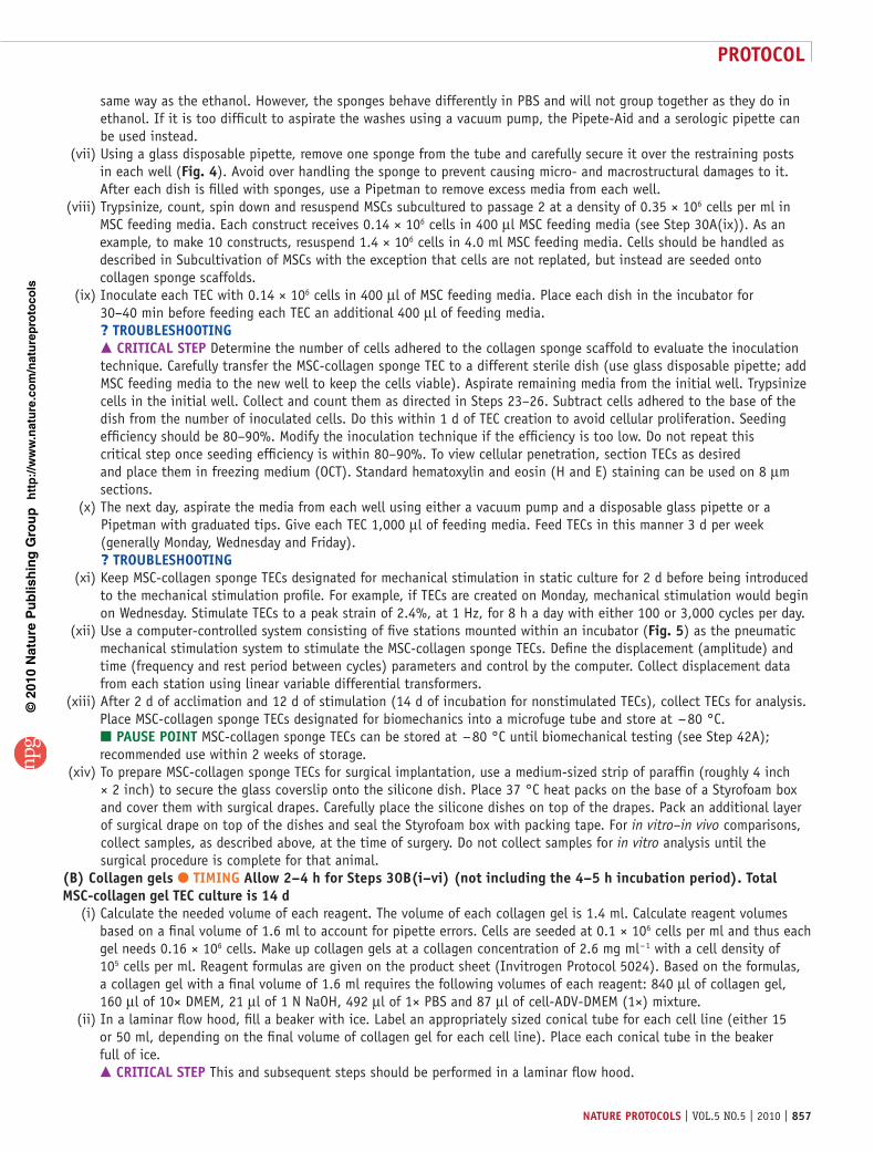
same way as the ethanol. However, the sponges behave differently in PBS and will not group together as they do in ethanol. If it is too difficult to aspirate the washes using a vacuum pump, the Pipete-Aid and a serologic pipette can be used instead.
(vii) Using a glass disposable pipette, remove one sponge from the tube and carefully secure it over the restraining posts in each well (Fig. 4). Avoid over handling the sponge to prevent causing micro- and macrostructural damages to it. After each dish is filled with sponges, use a Pipetman to remove excess media from each well.
(viii) Trypsinize, count, spin down and resuspend MSCs subcultured to passage 2 at a density of 0.35 × 10⁶ cells per ml in MSC feeding media. Each construct receives 0.14 × 10⁶ cells in 400 µl MSC feeding media (see Step 30A(ix)). As an example, to make 10 constructs, resuspend 1.4 × 10⁶ cells in 4.0 ml MSC feeding media. Cells should be handled as described in Subcultivation of MSCs with the exception that cells are not replated, but instead are seeded onto collagen sponge scaffolds.
(ix) Inoculate each TEC with 0.14 × 10⁶ cells in 400 µl of MSC feeding media. Place each dish in the incubator for 30–40 min before feeding each TEC an additional 400 µl of feeding media. ? trouBlesHootInG crItIcal step Determine the number of cells adhered to the collagen sponge scaffold to evaluate the inoculation technique. Carefully transfer the MSC-collagen sponge TEC to a different sterile dish (use glass disposable pipette; add MSC feeding media to the new well to keep the cells viable). Aspirate remaining media from the initial well. Trypsinize cells in the initial well. Collect and count them as directed in Steps 23–26. Subtract cells adhered to the base of the dish from the number of inoculated cells. Do this within 1 d of TEC creation to avoid cellular proliferation. Seeding efficiency should be 80–90%. Modify the inoculation technique if the efficiency is too low. Do not repeat this critical step once seeding efficiency is within 80–90%. To view cellular penetration, section TECs as desired and place them in freezing medium (OCT). Standard hematoxylin and eosin (H and E) staining can be used on 8 µm sections.
(x) The next day, aspirate the media from each well using either a vacuum pump and a disposable glass pipette or a Pipetman with graduated tips. Give each TEC 1,000 µl of feeding media. Feed TECs in this manner 3 d per week (generally Monday, Wednesday and Friday). ? trouBlesHootInG
(xi) Keep MSC-collagen sponge TECs designated for mechanical stimulation in static culture for 2 d before being introduced to the mechanical stimulation profile. For example, if TECs are created on Monday, mechanical stimulation would begin on Wednesday. Stimulate TECs to a peak strain of 2.4%, at 1 Hz, for 8 h a day with either 100 or 3,000 cycles per day.
(xii) Use a computer-controlled system consisting of five stations mounted within an incubator (Fig. 5) as the pneumatic mechanical stimulation system to stimulate the MSC-collagen sponge TECs. Define the displacement (amplitude) and time (frequency and rest period between cycles) parameters and control by the computer. Collect displacement data from each station using linear variable differential transformers.
(xiii) After 2 d of acclimation and 12 d of stimulation (14 d of incubation for nonstimulated TECs), collect TECs for analysis. Place MSC-collagen sponge TECs designated for biomechanics into a microfuge tube and store at − 80 °C. pause poInt MSC-collagen sponge TECs can be stored at − 80 °C until biomechanical testing (see Step 42A); recommended use within 2 weeks of storage.
(xiv) To prepare MSC-collagen sponge TECs for surgical implantation, use a medium-sized strip of paraffin (roughly 4 inch × 2 inch) to secure the glass coverslip onto the silicone dish. Place 37 °C heat packs on the base of a Styrofoam box and cover them with surgical drapes. Carefully place the silicone dishes on top of the drapes. Pack an additional layer of surgical drape on top of the dishes and seal the Styrofoam box with packing tape. For in vitro–in vivo comparisons, collect samples, as described above, at the time of surgery. Do not collect samples for in vitro analysis until the surgical procedure is complete for that animal.
(B) collagen gels ● tIMInG allow 2–4 h for steps 30B(i–vi) (not including the 4–5 h incubation period). total Msc-collagen gel tec culture is 14 d (i) Calculate the needed volume of each reagent. The volume of each collagen gel is 1.4 ml. Calculate reagent volumes
based on a final volume of 1.6 ml to account for pipette errors. Cells are seeded at 0.1 × 10⁶ cells per ml and thus each gel needs 0.16 × 10⁶ cells. Make up collagen gels at a collagen concentration of 2.6 mg ml − 1 with a cell density of 105 cells per ml. Reagent formulas are given on the product sheet (Invitrogen Protocol 5024). Based on the formulas, a collagen gel with a final volume of 1.6 ml requires the following volumes of each reagent: 840 µl of collagen gel, 160 µl of 10× DMEM, 21 µl of 1 N NaOH, 492 µl of 1× PBS and 87 µl of cell-ADV-DMEM (1×) mixture.
(ii) In a laminar flow hood, fill a beaker with ice. Label an appropriately sized conical tube for each cell line (either 15 or 50 ml, depending on the final volume of collagen gel for each cell line). Place each conical tube in the beaker full of ice. crItIcal step This and subsequent steps should be performed in a laminar flow hood.

p
uor
G g
n ih si l
bu
P eru ta
N 010 2©
nat
ure
pro
toco
ls/
moc. e r
ut an .
ww
w / /:pt t
h
protocol
858 | VOL.5 NO.5 | 2010 | nature protocols
(iii) Add the appropriate volumes of PBS, 10× ADV-DMEM and 1 N NaOH (in this order) to each conical tube on ice and mix thoroughly. The pH of this solution should be between 7 and 8. crItIcal step Keep all reagents in the refrigerator until ready for use, especially the collagen gel. ? trouBlesHootInG
(iv) Trypsinize, count and resuspend MSCs subcultured to passage 2 at the proper concentration in complete ADV-DMEM. (v) Add the appropriate volume of cell–ADV-DMEM mixture to each conical tube and mix thoroughly.
crItIcal step Avoid creating bubbles when mixing. Also, do not use a Pipete-Aid and serologic pipette to mix collagen gel and reagents because too much volume will be lost in the pipette and there will not be enough gel to create all the samples. Use a Pipetman with tips instead. crItIcal step Work quickly with cold reagents to avoid premature gelation.
(vi) Aliquot two 700 µl volumes of collagen gel mixture into each well. When each well is filled, place the dish in the incubator. Allow gels 4–5 h to set and then feed each gel 400–500 µl of complete ADV-DMEM. ? trouBlesHootInG
(vii) Feed collagen gels in the same manner as collagen sponges (TEC creation and culture, Collagen sponge, Step 30A(x)). Process collagen gels collected for in vitro analysis as required per the analysis protocol. For example, gels intended for picrosirius red staining should be cross-linked in 0.6% glutaraldehyde for 24 h and stored in 70% isopropyl at 4 °C until staining, whereas gels intended for alkaline phosphatase activity should be placed in lysis buffer and stored at − 80 °C. pause poInt MSC-collagen gel TECs can be stored as needed until testing. The acceptable storage time may depend on the anticipated test protocol. In general, recommended use is within 2 weeks of storage.
(viii) Prepare MSC-collagen gel TECs for surgery as described for MSC-collagen sponge TECs (See Step 30A(xiv)).
surgical implantation ● tIMInG 8–10 h for five rabbits. allow ½–2 h to prepare the surgical suite and animal prep/recovery room. the surgical implantation procedure takes 30–45 min per animal, depending on surgeon experience. each animal takes 1–4 h to recover from anesthesia31| Anesthetize the rabbit by injecting an anesthesia cocktail of ketamine and acepromazine (40 and 0.5 mg kg − 1, respectively). Using inhalation anesthesia, maintain the rabbit on isoflurane (2.0–2.5%) in oxygen using mask. Remove the fur between the hip and the ankle on both the right and the left hind limbs and on the abdominal cavity between the legs using electric clippers.! cautIon All procedures using live animals must be approved by the national and institutional regulations for animals used in research. Portions of this procedure may vary due to other IACUC guidelines and policies.
32| Place the rabbit on a surgical table over a circulating hot water blanket with its ventral surface exposed. Raise the hind limbs in a fully extended position to anchor for the sterile scrub. Use cords or gauze ropes to secure the limbs to an overhead surgical fixture (e.g., electric light) to support the limbs above the table.
33| Prepare the shaved area with Betadine and alcohol, alternating Betadine and alcohol three times using a circular motion and ending with alcohol scrub. Spray the area with Betadine solution as final preparation.
34| Using surgical drapes, cover the rabbit except for both lower extremities. Secure drapes in place with towel clamps where needed. Release the feet from tie restraints and catch the foot with sterile aluminum foil. Wrap the exposed fur on the unshaven foot with aluminum foil.
35| Pull the skin over the knee laterally and make a longitudinal, midline parapatellar incision over the PT from proximal of the patella to below the tibial tubercle using a #15 blade to expose the PT. Once the PT is visualized, use surgical scissors to open the peritenon sheath. Then, make two longitudinal incisions in the central third of the PT. The incisions should be 3 mm apart and extend from the patellar to tibial insertions. Carefully remove the central-third portion of the PT using lateral incisions at both the patellar and tibial insertions. crItIcal step The width of the incision should be less than one-third of the total width of the tendon and in the center of the tendon. Larger or off-center incisions frequently lead to patellar luxation.
36| Create bone defects in the patella and tibia using a sagittal saw in series with the tendon injury (2–3 mm long and 0.5–1.0 mm wide). Remove the cortical bone to expose the cancellous bone; this is visually confirmed when bleeding is observed in the bone defects (bone defects are approximately 1 mm deep). Wash away the bone particles with saline and remove any loose tendon material.
37| Remove the autologous MSC-collagen sponge TEC from its silicone culture dish and place it in a square of sterile gauze to compress the implant and remove excess culture media. Roll the TEC along its long axis to further compress the sponge and place into the surgical defect (Fig. 2b).

p
uor
G g
n ih si l
bu
P eru ta
N 010 2©
nat
ure
pro
toco
ls/
moc. e r
ut an .
ww
w / /:pt t
h
protocol
nature protocols | VOL.5 NO.5 | 2010 | 859
38| Create six equally spaced soft tissue, suture anchor points between the TEC and the remaining PT struts (three medial and three lateral) using 4-0 suture (we have also used 5-0 suture). Position the anchor points near the patellar and tibial insertions and in the middle of the defect. No other fixation method is required.
39| Remove the tension on the skin to restore the surgical opening to its original location. Close the subcutaneous adipose/fibrous tissue using continuous 4-0 suture. Close the skin with interrupted 3-0 suture.
40| Perform the same procedure on the contralateral limb using the control TEC.
41| When both skin incisions are closed, turn off the isoflurane and allow the rabbit to recover. Depending on the time under anesthesia, each animal may take 1–4 h to become alert and sternal. After surgery and recovery, animals should be allowed to roam free in cages. If complications arise during surgery or in recovery, consult your animal veterinary care specialist.
evaluation of response measures42| There are two spots in the protocol to evaluate response measures, after collecting TECs in vitro and after collecting repair tissue samples. TECs can be tested for linear stiffness (A) while repair tissues can be assessed for both biomechanics (B) and histology (C).(a) tec biomechanics ● tIMInG allow 5–10 min per construct for biomechanical testing (steps 42a(i–vii)) (i) Remove TECs from the freezer and allow them to thaw to room temperature (at 25 °C, constructs are generally thawed
and ready for testing in about 20 min). (ii) Rehydrate each TEC in PBS before testing. (iii) Measure the width and thickness of each TEC using calipers. (iv) Secure TEC ends into rubber-faced tensile testing grips and then place the grips in the single-column tensile test system
with no tension on the TEC. crItIcal step Make sure testing grips cover the ends of the TEC. The post holes should not be visible between the grips but should be completely covered by the grips.
(v) Manually adjust the actuator until the TEC is just taut. Then measure the grip-to-grip distance. (vi) Fail the TEC in uniaxial tension at strain rate of 10% per sec using MTestWR software. (vii) Determine the linear stiffness of each TEC by (a) plotting force versus displacement and (b) calculating the slope of
the linear region during loading.(B) repair tissue biomechanics ● tIMInG allow 10–20 min per animal to harvest hind limbs (step 42B(i)). thaw limbs over night. Depending on experience, 2–4 limbs can be tested in an 8–10 h period (i) After killing the animal, disarticulate the hind limbs at the hip and remove each limb using a scalpel. Store limbs
at − 20 °C until the day of testing. pause poInt Limbs can be stored at − 20 °C until testing. Recommended use within 2 weeks of storage.
(ii) The day before testing, thaw specimens in their own bags. crItIcal step Owing to the time required to prepare each sample, thaw no more than four limbs per day.
(iii) On the day of testing, mount one limb in a vice grip with suction base on a dissection table. Using scalpel, scissors and forceps, remove all extraneous tissue and muscle leaving only the PT attached to the patella and tibia.
(iv) Dissect away the medial and lateral fascia from the PT and remove the fat pad underneath the tendon. Using bone shears, cut the tibia at approximately 25–30 mm from the tibial plateau, preserving only the patella–PT–tibia complex.
(v) Using Vernier calipers, measure and record the length of the whole tendon along the medial, centerline and lateral aspects of the tendon. Measure the width of the tendon at the proximal, middle and distal portions of the tendon. Using a light force ( < 0.15 N) digital micrometer (IDC type, Mitutoyo Digimatic Indicator; MTI), measure and record the thickness of the whole tendon at the proximal, middle and distal portions of the tendon. Average the three recordings for length, width and thickness of the tendon.
(vi) Dissect away the medial and lateral struts of the PT (native tendon tissue) leaving only the patella–central-third repair tissue–tibia. Repeat Step 42B (v) to determine the average length, width and thickness of the repair tissue alone. crItIcal step Remove all the native struts from the repair tissue so as to only test the repair during the failure test. Use the suture marks inserted at surgery as a guide to isolate the repair tissue.
(vii) Mix the Dentsply repair material powder and liquid (200%, wt/vol). Use the bone cement (polymethylmethacrylate cement) to mount the patella into the patellar grip and the tibia into the tibial grip. Close the patella grip before the bone cement sets and close the tibial grip afterward. Allow the bone cement at least 30 min to set. Use gloves and avoid touching the bone cement as it sets because the reaction is exothermic.

p
uor
G g
n ih si l
bu
P eru ta
N 010 2©
nat
ure
pro
toco
ls/
moc. e r
ut an .
ww
w / /:pt t
h
protocol
860 | VOL.5 NO.5 | 2010 | nature protocols
crItIcal step Minimize direct contact between the tendon and the curing cement because the heat can damage the tendon.
(viii) Secure the testing grips into a PBS bath (pH 7.4, 37 °C) mounted on a testing system (Instron). (ix) Preload the sample to approximately 10 N and then precondition it for 50 cycles to 3% peak strain at 1 Hz using a
sine profile. Fail the sample in uniaxial tension at a strain rate of 20% per sec while continuously recording force and displacement (use the Instron WaveMatrix software to design a specimen failure program). ? trouBlesHootInG
(x) Plot the force–displacement and stress–strain curves to determine the structural (stiffness, maximum force) and material properties (modulus, maximum stress) of each sample. Stress is computed by dividing force values by average initial cross-sectional area and strain is computed by dividing displacement values by average initial tissue length. A sample size of 10–15 animals may be needed to establish statistical significance between testing groups.
(c) repair tissue histology ● tIMInG allow 10–20 min per animal to harvest hind limbs (step 42c(i)). steps 42c(ii–iv) take 7–10 d (potentially longer depending on the size of the bony ends). the time commitment of steps 42c(v–xiv) will vary depending on sample size and experience (expect an additional 1–10 d of histological processing) (i) Isolate the patella–central-third PT–tibia by cutting through the skin. Dissect the PT free on the lateral and medial
sides and away from the quadriceps muscle. Lift the patella–PT complex and trim away the underlying fat pad and the muscle from around the tibia. Use the bone shears to cut the tibia just below the tibial crest.
(ii) Fix samples in 10% neutral buffered formalin (NBF) at a volume of 10 parts NBF to 1 part sample. Secure tendons on a flat surface with slight tension to ensure proper fixation.
(iii) After 24–48 h, section samples to isolate (a) the patella and proximal PT, (b) the tendon mid-substance and (c) the tibia and distal PT.
(iv) Decalcify bone ends (patella and tibia) in 10% formic acid. Place the decalcified samples on a rocker plate. Change the decalcifying solutions daily. When bones are soft, they are ready for further processing.
(v) Dehydrate each section through a gradient of alcohols and xylene and embed the tissue in a paraffin block. (vi) Process the bony ends by cutting groups of eight serial sections (4 µm thick) in the sagittal plane spaced 1,000 µm
apart through the sample. Process the mid-substance by cutting groups of eight serial sections in the coronal plane spaced 250 µm apart through the sample.
(vii) Stain one section from each depth with H and E. (viii) Identify levels of interest at different depths and subject select relevant serial sections to immunohistochemical
staining for collagen type I, collagen type II (bone ends only), collagen type III, fibronectin and decorin. (ix) Before staining, perform antigen retrieval for collagen types I, II and III and fibronectin (not required for decorin).
Incubate collagen type I and collagen type III tissue sections in citrate buffer (pH 6.0) for 10 or 20 min in a steamer at boiling temperatures. Incubate collagen type II tissue sections in trypsin (0.25%) for 10 min at 37 °C. Incubate fibronectin-stained tissue sections in EDTA buffer (pH 8.0) for 10 or 20 min in a steamer at boiling temperatures. To optimize immunohistochemical staining, incubate collagen type I, collagen type III and fibronectin tissue sections for both 10 and 20 min durations and evaluate which is better for individual applications.
(x) To reduce background staining and nonspecific protein interactions, pretreat tissue and slides with avidin–biotin blocking kit and a serum block, respectively.
(xi) At each level, incubate serial tissue sections with primary monoclonal antibodies for anti-collagen types I (dilution 1:10,000), II (dilution 1:200), III (dilution 1:15,000), anti-decorin (dilution 1:100) and anti-fibronectin (dilution 1:16,000) for 1 h at room temperature.
(xii) Expose sections to goat anti-mouse (dilution 1:750) or rabbit anti-goat (60% dilution; decorin samples only) second-ary antibodies for 15 min followed by streptavidin–horseradish peroxidase conjugate (SA-HRP reagent ) for 15 min. Dilute primary and secondary antibodies with antibody diluent.
(xiii) Stain tissue sections with DAB + chromogen (3,3-diaminobenzidine tetrahydrochloride substrate for HRP) for 3 min and hematoxylin for 1 min.
(xiv) Dehydrate tissue sections through a gradient of ethanol washes and apply a coverslip. (xv) Evaluate repair tissue organization, cellularity and neovascularization, along with repair tissue integration into the
native tendon struts and formation of a tendon–bone insertion site using an inverted microscope.
● tIMInGSteps 1–3, Bone marrow harvest: 4–5 h for five rabbitsSteps 4–17, MSC isolation and expansion: 10–14 dSteps 18–29, Subcultivation of MSCs: 10–14 d per passage numberStep 30, TEC creation and culture: 15 d for collagen sponge TECs (A); 14 d for collagen gel TECs (B)

p
uor
G g
n ih si l
bu
P eru ta
N 010 2©
nat
ure
pro
toco
ls/
moc. e r
ut an .
ww
w / /:pt t
h
protocol
nature protocols | VOL.5 NO.5 | 2010 | 861
taBle 1 | Troubleshooting table.
step problem possible reasons solution
2 No marrow drawn out of the iliac crest
Several factors could lead to this. The biopsy needle has not yet passed into the marrow space or has passed through the iliac crest. It is also possi-ble even after trying to clear the canal of bone fragments that the opening is obstructed
To correct the first problem, replace the stylet and con-tinue to twist the needle clockwise and counterclockwise until the needle is seated in the marrow space. When properly inserted, the needle will maintain the orientation without the surgeon’s support. To determine if the needle has passed through the marrow space, apply light pressure to the needle. If it easily moves axially, then you have passed through the bone. To overcome this problem, either reharvest in a new location in the iliac crest or harvest from the right iliac crest, which has also been sterilely prepped. To eliminate an obstruction, either clear it with the stylus or remove the needle and clear it manually
The flow of marrow slows during collection
This could be attributed to a bone fragment obstructing the opening
To clear the obstruction, reinsert the stylet
The marrow is bright red and contains no fat
The biopsy needle has not passed through the cortical bone to the marrow space. Another potential cause is that the needle is not directed toward the marrow space
To correct this problem, continue to twist the needle clockwise and counterclockwise until the needle is seated in the marrow space. If needed, the biopsy needle can be withdrawn completely and reinserted at a different angle or in another location on the bone
6 Blood clot in syringe The marrow has been sitting in the syringe too long or not enough heparin was used at the time of the harvest
Carefully wipe clot onto a Kimwipe
10–11 Low yield of harvested bone marrow cells
A poor harvest in iliac crest Repeat harvest with correct depth and angle of biopsy needle. Check quality control for use of old/expired media or supplements
15 Obstructed view of colonies
Excess RBCs Gently swirl Dulbecco’s phosphate buffered saline (DPBS) over the cells and aspirate to help remove excess RBCs
22 Cells do not dissoci-ate from bottom of dish/flask
Presence of FBS may interfere with activity of trypsin
Rinse with DPBS twice to remove all traces of FBS. Check QC for proper storage and handling of trypsin
29 Cells did not grow Improper conditions in the incubator
Check incubator conditions for correct temperature (37 °C), 5% CO2 and humidity levels. If incubator conditions are correct, the animal may need to be reharvested. Expect a reharvest rate of about 26%
29 Nonadherent cells/no cells
Bacterial, fungal or mycoplasma contamination
Perform QC on media and cultures
30A(iv) After soaking in ethanol for 24 h, some areas of the sponge are white and appear dry
White/dry areas of the sponge have not absorbed ethanol
Use a sterile spatula to push the sponges against the wall of the tube until the dry area(s) is/are wetted with ethanol. This method can also be used to remove visible bubbles from the scaffolds
(continued)
Steps 31–41, Surgical implantation: 8–10 h for five rabbitsStep 42, Evaluation of response measures: 5–10 min per TEC for TEC biomechanics (A), 8–10 h for 2–4 limbs for repair tissue biomechanics (B) and 8–20 d for four patella-PT-tibia samples for repair tissue histology (C)
? trouBlesHootInGTroubleshooting advice can be found in table 1.

p
uor
G g
n ih si l
bu
P eru ta
N 010 2©
nat
ure
pro
toco
ls/
moc. e r
ut an .
ww
w / /:pt t
h
protocol
862 | VOL.5 NO.5 | 2010 | nature protocols
antIcIpateD resultsDuring the bone marrow harvest, we typically withdraw 2–5 ml of bone marrow. The bone marrow is deep red with distinct fat globules. After two centrifugation cycles of the bone marrow, the number of nucleated cells plated is 80–100 × 106 cells. During each passage (up to P2), the cells will typically become confluent 10–14 d after initial seeding. After the cells have reached P2 and the TEC has been created, the MSC-collagen gel TECs begin to contract within 24 h and continue to contract throughout the culture period with the majority of contraction occurring within the first 5 d. The MSC-gel TECs contract to a final volume approximately 31% of the initial volume28. In vitro linear stiffness meas-ured after 12 d of stimulation in culture yielded values of 0.011 ± 0.003 (mean ± s.e.m.)29, 0.024 ± 0.005 (ref. 29), 0.02 ± 0.01 (ref. 15), 0.045 ± 0.007 (ref. 26) and 0.068 ± 0.009 N mm − 1 (ref. 26) for unstimulated MSC-gel, stimulated MSC-gel, unstimulated MSC sponge, stimulated MSC sponge (100 cycles) and stimulated MSC sponge (3,000 cycles), respectively. The average failure curve for the 12-week repairs containing MSC-sponge constructs (mechanically stimu-lated at 2.4% strain for 100 cycles per day) matched the tangent stiffness of normal PT up to 150 N of force or 50% greater force than the peak IVF that we measured during hopping on a 6° inclined surface15,25. The failure properties for mechanically stimulated constructs were also significantly greater than those for nonstimulated constructs (Fig. 7). Histology for both the stimulated and the nonstimulated constructs yielded similar biochemical staining and cellular alignment to normal PT30.
taBle 1 | Troubleshooting table (continued).
step problem possible reasons solution
30A(v) Sponge gets stuck in the glass tip during aspiration
Aspirated too close to the sponge
Remove sponge and dispose of it. If the problem becomes frequent, use Pipet-Aid and serological pipette to aspirate instead. Cut 2–5 extra sponges to account for this problem
30A(ix) Low seeding efficiency Cells were not properly inoculated onto the scaffold
Use the pipette tip to ‘inject’ some of the media–cell mixture into the sponge (about half of the volume) and then slowly drip the remaining media–cell mixture on to the surface of the sponge. Do not rock the dish to disperse cells, this will only pull them off the sponge scaffold and onto the base of the well
30A(x) Media appear acidic (yellow) or basic (magenta/purple) between feedings
If the media appear yellow, cells may be very active. If media appear magenta/purple, cells may be dead
Supplement feedings with an additional half- or full-media change for the affected TECs. This is primarily seen over the second week of culture. A cell viability assay may be useful to elucidate the problem
30B(iii) pH is too high or too low
Too little or too much NaOH was used
Adjust volume of NaOH as needed
30B(vi) Gels do not solidify The pH of the mesenchymal stem cell (MSC)–collagen gel mixture was too high or too low (pH of the MSC–collagen gel mixture should be close to 7.4)
Most likely, the volume of NaOH needs to be adjusted. The volumes of other reagents, such as PBS and cell–ADV-DMEM mixture, should be modified to balance out changes in the volume NaOH (final volume must remain constant). The appropriate volumes of reagents can be determined by creating a gradient of gels in a 12-well plate. This allows for using lower volumes of reagents to determine which mixture will work best for individual applications. The formulas on the product sheet provide a good starting point but adjustments may be needed
42B(ix)
The sample slips out of the grip during testing
The sample was not properly mounted
Remount the sample, allow the bone cement to set and retest the sample. Compare the failure curves of the first and second test. If the first failure curve did not surpass a predetermined threshold (such as less than 40% of the second run’s max force), use the data from the second run to determine the sample’s biomechanics

p
uor
G g
n ih si l
bu
P eru ta
N 010 2©
nat
ure
pro
toco
ls/
moc. e r
ut an .
ww
w / /:pt t
h
protocol
nature protocols | VOL.5 NO.5 | 2010 | 863
acknoWleDGMents This research was supported by NIH Grants AR46574, AR56943 and EB002361. We acknowledge the assistance of Gino Bradica, Shun Yoshida, Tatiana Mavridis, Eric Schantz, Rita Angel, Angela M Sklenka, Heather Powell, Hani Awad, Matthew Dressler and Abhishek Jain.
autHor contrIButIons All the authors contributed extensively to the protocol described in this paper. D.L.B. and J.T.S. designed experiments, developed and refined the protocol, supervised data analysis and wrote the paper. C.G. gave technical support for cell culture, developed and refined the protocol and wrote the paper. K.R.C.K. designed and performed experiments, refined the protocol, analyzed data and wrote the paper. G.P.B. and M.T.G. designed experiments, performed surgical procedures and edited the paper. N.A.D. designed experiments, refined the protocol and wrote the paper. N.J.-M. and V.S.N. designed and performed experiments, developed and refined the protocol, analyzed data and edited the paper. All the authors discussed the results and implications of the findings.
coMpetInG FInancIal Interests The authors declare no competing financial interests.
Published online at http://www.natureprotocols.com/. Reprints and permissions information is available online at http://npg.nature.com/ reprintsandpermissions/.
1. Praemer, A., Furner, S. & Rice, D. In Musculoskeletal Conditions in the United States (American Academy of Orthopaedic Surgeons, Rosemont, IL, 1999).
2. Butler, D.L. et al. Functional tissue engineering for tendon repair: a multidisciplinary strategy using mesenchymal stem cells, bioscaffolds, and mechanical stimulation. J. Orthop. Res. 26, 1–9 (2008).
3. Butler, D.L. et al. Functional tissue engineering to repair tendon & other musculoskeletal tissues. MCB Mol. Cell. Biomech. 3, 127–129 (2006).
4. Butler, D.L., Shearn, J.T., Juncosa, N., Dressler, M.R. & Hunter, S.A. Functional tissue engineering parameters toward designing repair and replacement strategies. Clin. Orthop. Relat. Res. 427, S190–S199 (2004).
5. Guilak, F., Butler, D.L. & Goldstein, S.A. Functional tissue engineering: the role of biomechanics in articular cartilage repair. Clin. Orthop. Relat. Res. 391, S295–S305 (2001).
6. Butler, D.L., Goldstein, S.A. & Guilak, F. Functional tissue engineering: the role of biomechanics. J. Biomech. Eng-T ASME 122, 570–575 (2000).
7. Ouyang, H.W., Goh, J.C.H., Thambyah, A., Teoh, S.H. & Lee, E.H. Knitted poly-lactide-co-glycolide scaffold loaded with bone marrow stromal cells in repair and regeneration of rabbit Achilles tendon. Tissue Eng. 9, 431–439 (2003).
8. Juncosa-Melvin, N. et al. Effects of cell-to-collagen ratio in stem cell-seeded constructs for Achilles tendon repair. Tissue Eng. 12, 681–689 (2006).
9. Coleman, S.H. et al. Chronic rotator cuff injury and repair model in sheep. J. Bone Jt. Surg. Ser. A 85, 2391–2402 (2003).
10. Derwin, K.A. et al. Rotator cuff repair augmentation in a canine model with use of a woven poly-L-lactide device. J. Bone Jt. Surg. Ser. A 91, 1159–1171 (2009).
11. Derwin, K.A., Baker, A.R., Codsi, M.J. & Iannotti, J.P. Assessment of the canine model of rotator cuff injury and repair. J. Shoulder Elbow Surg. 16, S140–S148 (2007).
12. Soslowsky, L.J. et al. Overuse activity injures the supraspinatus tendon in an animal model: a histologic and biomechanical study. J. Shoulder Elbow Surg. 9, 79–84 (2000).
13. Moffat, K. et al. Novel nanofiber-based scaffold for rotator cuff repair and augmentation. Tissue Eng. Part A 15, 115–126 (2009).
14. Kuo, C. & Tuan, R. Mechanoactive tenogenic differentiation of human mesenchymal stem cells. Tissue Eng. Part A 14, 1615–1627 (2008).
15. Juncosa-Melvin, N. et al. Effects of mechanical stimulation on the biomechanics and histology of stem cell–collagen sponge constructs for rabbit patellar tendon repair. Tissue Eng. 12, 2291–2300 (2006).
16. Karaoglu, S. et al. Use of a bioscaffold to improve healing of a patellar tendon defect after graft harvest for ACL reconstruction: a study in rabbits. J. Orthop. Res. 26, 255–263 (2008).
17. Vieira, A., Guedes, R. & Marques, A. Development of ligament tissue biodegradable devices: a review. J. Biomech. 42, 2421–2430 (2009).
18. Liu, Y., Ramanath, H. & Wang, D. Tendon tissue engineering using scaffold enhancing strategies. Trends Biotechnol. 26, 201–209 (2008).
19. Awad, H.A. et al. Repair of patellar tendon injuries using a cell–collagen composite. J. Orthop. Res. 21, 420–431 (2003).
20. Young, R.G. et al. Use of mesenchymal stem cells in a collagen matrix for Achilles tendon repair. J. Orthop. Res. 16, 406–413 (1998).
21. Awad, H.A. et al. In vitro characterization of mesenchymal stem cell–seeded collagen scaffolds for tendon repair: effects of initial seeding density on contraction kinetics. J. Biomed. Mater. Res. 51, 233–240 (2000).
22. Harris, M.T. et al. Mesenchymal stem cells used for rabbit tendon repair can form ectopic bone and express alkaline phosphatase activity in constructs. J. Orthop. Res. 22, 998–1003 (2004).
23. Juncosa-Melvin, N. et al. Effects of cell-to-collagen ratio in mesenchymal stem cell-seeded implants on tendon repair biomechanics and histology. Tissue Eng. 11, 448–457 (2005).
24. Shearn, J.T. et al. Mechanical stimulation of tendon tissue engineered constructs: effects on construct stiffness, repair biomechanics, and their correlation. J. Biomech. Eng. 129, 848–854 (2007).
25. Juncosa, N., West, J., Galloway, M., Boivin, G. & Butler, D. In vivo forces used to develop design parameters for tissue engineered implants for rabbit patellar tendon repair. J. Biomech. 36, 483–488 (2003).
26. Nirmalanandhan, V. et al. Improving linear stiffness of the cell-seeded collagen sponge constructs by varying the components of the mechanical stimulus. Tissue Eng. Part A 14, 1883–1891 (2008).
27. Aurora, A., McCarron, J., Iannotti, J. & Derwin, K. Commercially available extracellular matrix materials for rotator cuff repairs: state of the art and future trends. J. Shoulder Elbow Surg. 16, S171–178 (2007).
28. Nirmalanandhan, V.S., Levy, M.S., Huth, A.J. & Butler, D.L. Effects of cell seeding density and collagen concentration on contraction kinetics of mesenchymal stem cell-seeded collagen constructs. Tissue Eng. 12, 1865–1872 (2006).
29. Nirmalanandhan, V. et al. Effect of scaffold material, construct length and mechanical stimulation on the in vitro stiffness of the engineered tendon construct. J. Biomech. 41, 822–828 (2008).