based scaffolds for neural regeneration - TigerPrints
135
Clemson University TigerPrints All Dissertations Dissertations 5-2015 CAPILLARY CHANNEL POLYMER FIBER- BASED SCAFFOLDS FOR NEUL REGENETION Atanu Sen Clemson University, [email protected] Follow this and additional works at: hps://tigerprints.clemson.edu/all_dissertations Part of the Engineering Commons is Dissertation is brought to you for free and open access by the Dissertations at TigerPrints. It has been accepted for inclusion in All Dissertations by an authorized administrator of TigerPrints. For more information, please contact [email protected]. Recommended Citation Sen, Atanu, "CAPILLARY CHANNEL POLYMER FIBER-BASED SCAFFOLDS FOR NEUL REGENETION" (2015). All Dissertations. 1511. hps://tigerprints.clemson.edu/all_dissertations/1511
-
Upload
khangminh22 -
Category
Documents
-
view
0 -
download
0
Transcript of based scaffolds for neural regeneration - TigerPrints

Clemson UniversityTigerPrints
All Dissertations Dissertations
5-2015
CAPILLARY CHANNEL POLYMER FIBER-BASED SCAFFOLDS FOR NEURALREGENERATIONAtanu SenClemson University, [email protected]
Follow this and additional works at: https://tigerprints.clemson.edu/all_dissertations
Part of the Engineering Commons
This Dissertation is brought to you for free and open access by the Dissertations at TigerPrints. It has been accepted for inclusion in All Dissertations byan authorized administrator of TigerPrints. For more information, please contact [email protected].
Recommended CitationSen, Atanu, "CAPILLARY CHANNEL POLYMER FIBER-BASED SCAFFOLDS FOR NEURAL REGENERATION" (2015). AllDissertations. 1511.https://tigerprints.clemson.edu/all_dissertations/1511

CAPILLARY CHANNEL POLYMER FIBER-BASED SCAFFOLDS FOR NEURAL REGENERATION
A DissertationPresented to
the Graduate School of Clemson University
In Partial Fulfillment of the Requirements for the Degree
Doctor of Philosophy Bioengineering
by Atanu Sen May 2015
Accepted by: Dr. Ken Webb, Committee Chair
Dr. Frank Alexis Dr. Alexey Vertegel
Dr. Bruce Gao

ABSTRACT
Over 50 million Americans are affected by ailments to the central nervous system
(CNS) and it impacts the American economy over $400 billion a year. The number of
people in the United States who have spinal cord injury (SCI) has been estimated to be
approximately 276,000 persons as of 2014 with a range from 240,000 to 337,000 persons.
The annual incidence of SCI, not including those who die at the scene of the accident is
approximately 12,500 new cases each year. Due to the limited regenerative capacity of
the adult CNS and lack of clinically effective therapies, these conditions commonly result
in permanent functional deficits. SCI damages both ascending sensory and descending
motor axonal pathways interrupting the transmission of synaptic signals between the brain
and peripheral tissues. Although damaged axons attempt an initial regenerative response,
this is rapidly aborted due to the presence of growth inhibitory molecules in CNS myelin
and the glial scar and intrinsic limitations of adult CNS neuronal biochemistry such as the
ability to maintain cAMP levels and upregulate the expression of ‘regeneration-associated
genes’. On the other hand, TBI, stroke, and Parkinson’s disease result in neuronal cell
death. The CNS has limited capacity to replace lost neurons because the neurons
themselves are terminally differentiated and post-mitotic. Although neural stem cells
(NSCs) have been identified in specialized regions of the adult brain such as the sub-
ventricular zone (SVZ) and the sub-granular zones (SGZ), their number is insufficient and
the pathological environment inadequate to support an effective regenerative response.
The end goal of this project is to develop a biomimetic scaffold using grooved fibers
for neural regeneration. This goal was met with a two-pronged approach. In the first
approach, grooved fibers immobilized with bioactive adhesive molecule were developed
to topographically guide regenerating axons. In the second approach, grooved fiber
ii

staples were used as cell-laden microcarriers and integrated into a composite hydrogel
which demonstrated its ability to serve as a platform for cell proliferation. This latter
approach can be translated into an injectable in situ crosslinkable scaffold that can be
used for neural stem cell (NSC) delivery with the prospect of stem cell differentiation into
neurons to replenish cell loss.
The first part of this research focused on immobilizing a bioactive 140 kDa
fragment of L1 neural cell adhesion molecule on uniquely designed groovy capillary
channel polymer (CCP) fibers. L1-CAM is an attractive candidate for growth of spared
axonal growth cones upon injury. It mediates CNS maturation, by means of neurite
outgrowth, adhesion, fasciculation, migration, survival, myelination, axon guidance,
synaptic plasticity and regeneration after trauma. High levels of L1 are expressed by
growing axons during development and after SCI and there is a positive correlation
between their expression and axonal growth. CCP fibers with surface immobilized L1-
CAM were demonstrated to guide growth of primary neurons in vitro. In the latter part of
this research, a methodology to fabricate CCP fiber staples was developed and these
were employed as cell-laden microcarriers. These microcarriers were then integrated into
a composite hydrogel blend and demonstrated high cell proliferation in vitro compared to
control gels. This composite system can be a promising platform for NSC delivery and
differentiation into neurons.
iii

ACKNOWLEDGMENTS
The Department of Bioengineering has been my safe haven for my stay
here at Clemson University. Ever thankful for this opportunity to serve as research
and teaching assistant at this wonderful institution. I would like to thank Prof.
Martine LaBerge – Chair of Department of Bioengineering, for her belief in me and
to provide me an opportunity to pursue my PhD. No words to describe the support
given to me by our department’s graduate student coordinator – Ms. Maria Martin.
Maria, all your support during tough times have been invaluable and helped me
enormously for all these years, can never forget and cannot be thankful enough. I
would like to thank my committee members – Prof. Frank Alexis, Prof Alexey
Vertegel and Prof. Bruce Gao for their guidance and support.
“A teacher Takes a hand Opens a mind Touches a heart Shapes the future”
"A disciple is not a vessel to be filled, but a lamp to be lit."
These words are for my mentor Prof. Ken Webb. Working with Prof. Webb
over the years, I realized things more than just science, probably I realized ‘life’. I
remember once in my early stages, he had mentioned in a one on one meeting:
‘Your success is very important to me’. And with time I realized how he meant
every word of it. I learned the virtues of ‘patience’ and ‘perseverance’ from
numerous failed experiments in the laboratory, which in course of time became the
mantra for life in general. His utmost respectful, humble and kind attitude towards
other fellow human beings is a trait that I always appreciate and try to emulate,
iv

and probably it rubbed into me overtime. I appreciate the considerable time and
effort invested by him in correcting abstracts and manuscripts on innumerable
occasions. ‘Thank you’ Prof. Webb for the opportunity and for shaping my
character and my life.
I was fortunate to have labmates – Jeremy Zhang, Ho-Joon Lee and
Sooneon Bae with whom I had a smooth sail and never had any issues. I
acknowledge Dr. Jeoung Soo Lee for scientific discussions and guidance to my
project at times. Two colleagues deserve special mention – Srikanth Sivaraman
and Saketh Ram Karamched, thankful for your much needed support towards the
finish.
I would like to extend my gratitude to my Maa, Baba and my sister. I know
I did you proud with my achievement, eternally grateful for your unconditional love
and support. Special thanks to my maternal aunt Leena Barua in Canada, your
support through all these years and especially in the finishing stages have been of
enormous help. Shout out to my buddies across the globe – Bishal Nath (India),
Vikas Kohli (Canada) and Srikant Chandrashekaran (Australia); you have been
awesome, thanks for the happy times you have time and again given to me, and
look forward to more and more such times ahead.
v

TABLE OF CONTENTS
Page
TITLE PAGE ....................................................................................................... i ABSTRACT ........................................................................................................ ii ACKNOWLEDGMENTS ................................................................................... iv LIST OF TABLES ............................................................................................... x LIST OF FIGURES ........................................................................................... xi CHAPTER
1. INTRODUCTION ..................................................................................... 1 CNS injuries and diseases ......................................................................... 1 Structure/Function of PNS and CNS .......................................................... 4 Pathology of nerve injury ........................................................................... 7 PNS injury ......................................................................................... 7 CNS injury ......................................................................................... 8 Topographic guidance approaches: How to bridge the gap? ................... 10
Autologous non-nerve grafts .................................................................... 14
Non-autologous non-nerve grafts ............................................................. 14
Biologically derived polymers ................................................................... 14
Synthetic polymers ................................................................................... 15
Topographic guidance using photolithographic anisotropic
grooved features ................................................................................ 17
Topographic guidance using electrospun fibers ................................. 22
Stem cell differentiation in response to topography ................................. 31
CCP fiber scaffolds for tissue regeneration .............................................. 35
Role of cell adhesion molecules (CAMs) in nervous system .................... 36
Role of L1-CAM in axonal growth ....................................................... 38
Conclusion ................................................................................................ 44
References................................................................................................ 46
vi

TABLE OF CONTENTS (contd.) Page
2. AIMS AND RATIONALE .............................................................................. 52
3. ENGINEERING GUIDED NEURON GROWTH USING CCP FIBERS ........ 56
Introduction .................................................................................................. 56
Materials and methods ................................................................................. 59
Fabrication of CCP fibers ................................................... 59
Morphology and characterization of CCP fibers ................. 59
Expression and purification of L1-CAM .............................. 60
Preparation of 2D polystyrene samples ............................. 60
Preparation of 2D spin cast polylactide samples61
Preparation of 3D fiber samples ......................................... 61
Cell preparation .................................................................. 62
Cell adhesion and neurite outgrowth on 2D polystyrene,
PLLA spin cast film and 3D fiber samples ......................... 63
Immunohistochemical staining .......................................... 63
Scanning electron microscopy .......................................... 64
Statistical analysis ............................................................. 64
Results and discussion ....................................................................... 62
Effect of L1-CAM concentration on neurite length in 2D ... 65
Effect of ligand on neurite length in 2D ............................. 66
Fabrication of extruded PLLA CCP fibers ......................... 69
Effect of fiber dimensions on neurite extension ................. 70
Effect of CCP biofiber topography and biochemical cue L1-CAM on neurons and tissue explants ................................................ 71 Conclusion ....................................................................................................... 75 References ...................................................................................................... 76
4. ENGINEERING CELL PROLIFERATION USING TOPOGRAPHY AND HYDROGEL ................................................................................................. 76 Introduction .................................................................................................. 76
vii

TABLE OF CONTENTS (contd.)
Chapter Page
Materials and methods ..................................................................................... 81 CCP fiber staple fabrication & characterization ......................... 81
Cell culture and seeding on staples .......................................... 82
Validation of injectability ........................................................... 84
Synthesis of PEG-DA macromers with ester linkages containing
variable alkyl spacers ............................................................... 84
Preparation of staple-hydrogel composites .............................. 85
Confocal imaging ..................................................................... 85
Cell proliferation ....................................................................... 86
Statistical analysis .................................................................... 86
Results ...................................................................................................................... 87
Preparation of CCP staples ....................................................... 87 Cell culture and seeding on staples ........................................... 88
Validation of injectability ............................................................ 88
Cell-staple encapsulation and growth within
hydrogel composites ................................................................ .89
Discussion ................................................................................................................. 94
Conclusion ................................................................................................................ 97
References ................................................................................................................ 98
5. ENGINEERING STEM CELL FATE USING COMPOSITE SCAFFOLD .............. 101
Introduction ......................................................................................................... 101
Materials and Methods ........................................................................................ 106
Preparation of 2D spin cast samples ....................................... 106
Preparation of fiber samples ................................................... 107
Cell culture and seeding.......................................................... 107
Immunostaining of mNSCs ..................................................... 108
Synthesis of PEGdA macromers with ester linkages containing
variable alkyl spacer ……………………………………………….109
viii

TABLE OF CONTENTS (contd.)
Chapter Page
Preparation of staple hydrogel composites.............................. 109
Results .................................................................................................................... 110
Validation of CCP staples as NSC microcarrier ........................ 110
Investigation of NSC differentiation ......................................... 111
Discussion ............................................................................................................... 114
Conclusions ............................................................................................................ 116
References .............................................................................................................. 117
6. CONCLUSIONS AND FUTURE RECOMMENDATIONS ..................................... 119
ix

LIST OF FIGURES
Figure Page
Fig.1.1. Anatomy overview of the spinal cord ............................................................. 6 Fig.1.2. Responses to axotomy in the (a) PNS and (b) CNS ....................................... 7 Fig.1.3. Properties of the ideal nerve guidance channel ............................................ 12 Fig.1.4. Tubes or guide types for peripheral nerve repair .......................................... 13 Fig.1.5. Topographies presented to neurons in vitro ................................................. 17 Fig.1.6. Scanning electron micrograph of DRG after 24 h culture on laminin-coated, micropatterned PDMS substrate .................................................................. 18 Fig.1.7. (Left) Schematic representation of electrospinning apparatus (Right) Different types of fiber collectors. (a) Plate type; (b) cylinder type; (c) disc type ...................................................................................... 24 Fig.1.8. (Top) SEM micrographs of PLLA (left) ANF (right) RNF; (Bottom) Phase contrast micrographs of NSC growth on (left) ANF (right) RNF ................................. 25
Fig.1.9. (Left)-Scanning electron micrographs of micropatterned polymeric films (Right)- Formation of 3D construct and various cross sectional views of the construct by SEM ............................................................................. 26 Fig. 1.10. (Left) Immunofluorescence staining of NSCs seeded on aligned 2D and 1D STEP-aligned, polystyrene fiber meshes (Right) Quantification of immunofluorescence staining of NSCs ............... 34 Fig.1.11. Cross-sectional view of CCP fibers ............................................................ 36
Fig.1.12. Schematic of L1-CAM ................................................................................ 38
Fig.1.13. Left- Homophilic binding of L1 in horseshoe or extended forms; Right- Modular and cooperative binding of L1 with different molecules .............................................. 39
Fig.1.14. Sequence of events at region of neuron attachment .................................. 40
Fig.1.15. Four distinct mechanisms involved in the inside-out regulation of IgCAM-mediated adhesion .................................................................................................... 41
Fig.1.16. (a). Left- Molecular mechanism of L1-mediated growth cone migration (b). L1 interaction at its cytoplasmic domain with other cytoplasmic proteins (c). Cytoskeletal organization and actin dynamics in growth cones. (d). Schematic of Spectrin which plays a role in actin polymerization by binding to ankyrin .................................................... 42
x

LIST OF FIGURES (contd.)
Figure Page
Fig.1.17. Left- Clathrin triskelion structure; Right- Model of dynamin-mediated
pinching off clathrin/AP-coated vesicles .................................................................... 43
Fig. 1.18. Proposed L1-signaling pathway ................................................................ 44
Fig.3.1. Dose dependent neurite extension response of L1-CAM in 2D polystyrene
on rat cerebellar neurons .......................................................................................... 65
Fig.3.2. Dissociated Chicken forebrain neurons on different ligands ......................... 67
Fig.3.3. Comparison of neurite length extension in 2D on PLA coated with different
ligands ...................................................................................................................... 68
Fig.3.4. (a). Scanning electron microscope image of a resin embedded capillary
channel polymer fiber cross-section (x900) (b). SEM of CCP fibers (x120)
(c). Fiber microtopography dimensions of 7 different dpf CCP
fiber samples ............................................................................................................. 69
Fig.3.5. Effect of groove dimensions of CCP fibers on neurite extension was
quantified with dissociated CFN neurons ................................................................... 70
Fig.3.6. Effect of CCP biofiber topography on postnatal rat cerebellar neuron
explants ..................................................................................................................... 72
Fig.3.7. Effect of CCP biofiber topography on E8 chicken forebrain neuron explants 73
Fig.3.8. Topographic guidance of cDRG neurons ..................................................... 74
Fig.3.9. a). Primary chick embryonic forebrain dissociated neurons cultured on
L1-CAM adsorbed CCP fibers in 3D .......................................................................... 75
Fig.4.1. Schematic of 3T3 fibroblast cell seeding and culture in 3D hydrogel
composites ................................................................................................................ 83
Fig.4.2. SEM image of CCP staples .......................................................................... 87
Fig.4.3. 3T3 cells on CCP staples after 48 hours in culture ....................................... 88
xi

LIST OF FIGURES (contd.)
Figure Page
Fig.4.4. Injectability of CCP seeded 3T3 fibroblasts stained live with Calcein AM
through 21G needle................................................................................................... 89
Fig.4.5. Cell adhesion to staples 48 hours post seeding (a). Round cross-section
staples show aggregate formation (b). CCP cross-section staples show no
aggregation and well dispersed ................................................................................. 90
Fig.4.6. Fluorescent images of live 3T3 fibroblasts grown in hydrogel composites (PEGdA/HA/PLA staples) .......................................................................................... 91
Fig.4.7. Fluorescent images of live 3T3 fibroblasts grown in hydrogel
controls (PEGdA/HA) ................................................................................................ 92
Fig.4.8. 3D Z-stack image of fibroblasts in gels ......................................................... 92
Fig.4.9. Proliferation of NIH3T3 fibroblasts in hydrogel composites
(PEGdA/HA/Staples) and PEGdA/HA controls .......................................................... 93
Fig.5.1. Pathways that are involved in the generation, action and catabolism of
Retinoic acid ........................................................................................................... 105
Fig.5.2. SEM image showing NSCs on CCP staples after 48 hours in culture
SEM image ............................................................................................................. 110
Fig.5.3. Fluorescence mages of NSCs polylysine coated TCP (tissue culture plastic)
after 8 days of cell culture ....................................................................................... 111
Fig.5.4. Fluorescence mages of NSCs on two dimensional planar polylactide (PLA)
films after 8 days of cell culture .............................................................................. 112
Fig.5.5. Fluorescence mages of NSCs on three dimensional CCP fibers
after 8 days of cell culture ....................................................................................... 113
xii

LIST OF TABLES
Table Page
Table 1. CCP fibers of different dimensions made by varying extrusion conditions ... 59
xiii

CHAPTER ONE
INTRODUCTION
1. CNS injuries and diseases (TBI, SCI, Neurodegenerative diseases)
Over 50 million Americans are affected by ailments to the central nervous system
(CNS) and it impacts the American economy over $400 billion a year. Traumatic insults to
the central nervous system (CNS) such as in spinal cord injury (SCI) and traumatic brain
injury (TBI), result in impaired motor and sensory functions; cystic cavity and glial scar
formation thereby causing disruption of signaling pathways. Apart from spinal cord injury
(SCI) and traumatic brain injury (TBI), neurological diseases such as Alzheimer’s disease,
Parkinson’s disease, and Huntington’s disease result in neuronal loss. Furthermore, if
blood supply is impaired by hemorrhage or ischemia, the functional consequences
worsen, as the CNS has limited capability to replace or regenerate lost neurons. In the
adult CNS, the damaged axons do not regenerate spontaneously because of the extrinsic
inhibitory environment and their intrinsic limited regenerative ability as well. In addition,
replacement of lost neurons in debilitating cases of neurodegeneration by neural stem
cells is also limited in the adult CNS. However, it is now known that various neural
engineering and neuroprotective strategies can enable regeneration and replacement of
surviving and lost neurons respectively. One approach to engineering the SCI pathology,
is to transplant physical support that provides topographic cues for directional guidance.
Such topographic support should be able to mimic the native ECM (extracellular matrix)
environment of the neuronal niche. Other approaches include cellular therapy wherein
1

transplanted cells provide trophic biochemical support and can also replenish lost neurons
by differentiating in response to the environmental niche at the defect site.
1.1.1 Spinal Cord Injury (SCI)
The number of people in the United States who have spinal cord injury (SCI) has
been estimated to be approximately 276,000 persons as of 2014 with a range from
240,000 to 337,000 persons [1]. The annual incidence of SCI, not including those who die
at the scene of the accident is approximately 12,500 new cases each year. This greatly
compromises the quality of life of affected individuals and has a significant socioeconomic
impact. The average individual cost borne with just SCI cases is $250,000 and amounts
to a sum of about $10,000,000,000 in medical expenses every year. The pathophysiology
of SCI involves two stages [2]. The primary injury involves initial mechanical infliction
which results in direct compression of the spinal cord by bone fragments and spinal cord
disc material that causes damage to axons and neuron membrane. The spinal cord can
swell in this situation resulting in secondary ischemia. The secondary injury cascade
involves cell apoptosis in response to toxic chemicals released from damaged cells, axons
and blood vessels in addition to glutamate excitotoxicity. The neural engineering challenge
comes in to reinnervate surviving axons by guidance from the rostral to the caudal end
across the gap to restore the neuronal circuit.
1.1.2 Traumatic Brain Injury (TBI)
Traumatic brain injury (TBI) is one of the major causes of morbidity in the United
States, impacting the lives of 1.5 million new patiently annually. The annual mortality due
to TBI amounts to approximately 50,000 contributing to about 30% of all injury deaths [3]
with an additional 230,000 patients requiring hospitalization. As of 2010, about 2.5 million
2

patients exist overall in US itself while approximately 6.5 million exist worldwide [4]. The
repurcussions can last from anywhere between few days to lifetime disabilities. The
severity of a TBI may range from mild to severe. A mild injury would result in a brief change
in mental status or consciousness while severe case would involve in an extended period
of unconsciousness or amnesia after the injury. The effects involved with TBI can include
impaired thinking or memory, movement, sensation (e.g., vision or hearing), or emotional
functioning (e.g., personality changes, depression). TBI is often referred to as a ‘silent
epidemic’ because of these complications may not be obvious. These issues not only
affect the patients but can have lasting socioeconomic effects on families and
communities. Neurons show limited ability for repair and no therapy exists currently to
reverse the neuronal injury complications. Unlike SCI, TBI involves neuronal cell death
and requires cell replacement strategies.
1.1.3. Stroke
Brain stroke is the second leading cause of death worldwide. It can be classified
into hemorrhagic, ischemic or embolic in origin. 500,000 new cases of brain strokes are
reported each year in the US itself, which causes a great socioeconomic burden of
approximately $54 billion/year absorbing 6% of the health care budgets. Ischemic stroke
accounts for the majority of the stroke types, amounting to 80% of all brain strokes.
Although no effective treatment is available for cerebral ischemic stroke till date, current
treatments focus on thrombolysis and neuroprotection, which have demonstrated limited
benefits in few patients. Most neuroprotective drugs investigated for stroke have failed in
clinical trials during the last two decades [5].
3

1.1.4 Parkinson’s disease (PD)
PD is a neurodegenerative disorder that affects movement and balance in addition to
impairing cognitive abilities. It is found in 2% of the adult population over 65. These
symptoms are triggered by the loss of dopaminergic (DA) neurons in the substantia nigra
as well as a decrease in the levels of dopamine in the caudate and putamen. The current
treatment method is administration of oral L-3, 4-dihydroxyphenylalanine (L-DOPA), which
can be converted to dopamine in the body. However, this treatment is less effective with
progression of degeneration with adverse effects as dyskinesias (movement disorders that
are characterized by involuntary muscle movements) [6, 7].
1.2. Structure/Function of PNS and CNS:
The nervous system consists of the central nervous system (CNS) and the peripheral
nervous system (PNS). The CNS includes the brain, spinal cord, optic, olfactory and
auditory systems. It conducts and interprets signals conducted to it by the sensory neurons
and also provides excitatory stimuli to the PNS. The PNS includes the cranial nerves from
the brain, the spinal nerves from the spinal cord, sensory nerve cell bodies (dorsal root
ganglia) and their processes. Peripheral nerves innervate muscle tissue, transmitting
sensory and excitatory input to and from the spinal column [8, 9].
The spinal cord can be anatomically divided into the cervical, thoracic, lumbar,
sacral, and coccygeal regions. The center of the spinal cord is a butterfly-shaped region
referred to as gray matter which contains the somata, neuroglia and blood vessels. The
gray matter is ensconced within the white matter which consists of axons and neuroglia.
The nerves on each side of the cord are subdivided into roots. The dorsal root carries
sensory/afferent neurons which conduct sensory information to the CNS while ventral root
carries motor/efferent neurons which convey the response from the CNS to the
4

end/effector organs such as muscles and glands. The cell bodies of the sensory neurons
are located in the dorsal root ganglia just next to the spinal cord while the cell bodies of
the motor neurons are located in the ventral horns of the spinal cord or brainstem (Fig.1.1).
In the PNS, nerve fibers are enveloped in a protective sheath called endoneurium
composed predominantly of oriented collagen fibers. Several axons are bundled together
into fascicles, each surrounded by a protective sheath known as the perineurium formed
from many layers of fibroblasts and collagen. Several fascicles are bundled together by
the outermost connective tissue layer called epineurium composed of loose
fibrocollagenous tissue forming the anatomically defined nerve cable/trunk. Peripheral
nerves are well vascularized by capillaries within the support tissue of the nerve trunk or
by vessels that penetrate the nerve from surrounding arteries and veins.
The cellular components of the nervous system are neurons and glial cells. Neurons
are the basic structural and functional elements of the nervous system consisting of a cell
body (soma or perikaryon) from which axons and dendrites emanate. Dendrites transmit
electrical signals to the soma from preceeding neurons and the axon conducts impulses
away to the next neuron. Sensory nerve soma cluster into ganglia. Glial cells also referred
to as neuroglia include Schwann cells which ensheath axons in the PNS and astrocytes
and oligodendrocytes in the CNS. These are support cells that aid the functioning of
neurons. A basement membrane called neurilemma envelopes the outer surface of this
Schwann cell layer. CNS axons lack the neurilemma but have insulating myelin sheath
formed by oligodendrocytes. Similarly, in PNS, the Schwann cells produce myelin which
serves to increase the propagation velocity of the nerve impulse. Astrocytes create the
blood-brain barrier that barricades the CNS from blood proteins and cells.
5

Fig.1.1 Anatomy overview of the spinal cord (a) The spinal cord anatomy (b,c) Cross-section of the spinal cord showing gray,white matter and neighboring ganglia (d) Connective tissue arrangement of the nerve bundle [8]
d
6

1.3. Pathology of nerve injury:
Fig.1.2. Responses to axotomy in the (a) PNS and (b) CNS [8, 10].
1.3.1. PNS injury:
The most severe PNS injury results in complete nerve transection. Such trauma results
in axons being torn away from their cell bodies and eventually degrade; the distal stump
of the transected nerve undergoes anterograde degeneration accompanied by
disintegration of the cytoskeleton and cell membranes into their molecular constituents
and shedding of myelin by the endogenous Schwann cells and PNS glial cells. This
degeneration phenomena is referred to as Wallerian degeneration (WD) - a process that
occurs before nerve regeneration and can be described as a myelin and neuronal debris
cleaning/clearing process that essentially prepares the distal stump for reinnervation [11].
WD commences with axoplasm and axolemma degradation induced by activation of
7

axonal proteases and calcium influx. The success of regenerative response depends on
the sparing of connections between the proximal fiber fascicles and the endoneurium of
the severed distal segments. In case of a crush lesion, the continuous endoneurial basal
lamina provides guidance for regenerating axons from the proximal nerve stump to the
distal end. However in case of axotomy, complete separation of the proximal and distal
stumps impedes reinnervation and often leads to the formation of neuroma [12]. At the
transection site, Schwann cells (SCs) infiltrate to clear the myelin and neuronal debris by
phagocytosis. Hematogenous macrophages are recruited by SC induced chemoattraction
[12]. Both macrophages and SCs also produce neurotrophin cytokines to enhance axon
growth. Schwann cells are involved in ECM production and are a versatile source of
trophic factors [13]. After the initial extrusion of myelin sheaths, the Schwann cells having
lost contact with the viable axons dedifferentiate and proliferate by mitosis to align within
the remnant basal lamina endoneurial tubes to form bands of Büngner, which provides a
growth substrate for the growth cone formed at the tip of the severed axon in the proximal
nerve stump. This growth cone transduces guidance cues into intracellular signals for
neurite extension and orientation extending into the ECM, retracting upon encountering
inhibitory molecules or in absence of positive cues [14].
1.3.2. CNS injury:
In case of SCI, the spinal cord generally experiences 4 types of forces namely –
flexion, extension, rotation and compression. A combination of two of more of these forces
may lead to injury that can result in dislocated vertebrae and fractured vertebral bodies.
Such injuries lead to concussion, contusion or laceration of the spinal cord. In case of
concussion, no transient loss of function resulting in anatomical damage is involved.
8

However, contusion and laceration injuries involve anatomical damage that lead to
permanent deficits [15].
SCI response can be listed into 3 phases upon injury – acute phase, subacute
phase and late chronic phase. The acute phase occurs immediately upon injury and is
characterized by mechanical damage to neural and other soft tissues, including
endothelial cells of the vasculature resulting in hemorrhage, localized edema, and loss of
microcirculation by thrombosis and vasospasm. Hemorrhage begins in the highly
vascularized gray matter near the central canal and spreads radially to the posterior horns
and into the white matter [16]. Over a time course of minutes to weeks the debilitating
effects of ischemic cellular death, ionic shifts (formation of free radicals), release of nitric
oxide and proteases, and edema continue from the acute phase [17]. The spinal cord
parenchyma is invaded by the inflammatory cells. Apoptosis i.e. cell death occurs and
involves reactive gliosis that includes the increased expression of glial fibrillary acidic
protein (GFAP) and astrocytic proliferation. The subacute phase follows necrosis and is
accompanied with inflammatory response due to microglia and astrocyte mediate reactive
gliosis along with disruption of the blood-brain barrier which allows blood-borne immune
cells from the periphery to infiltrate the spinal cord. Upregulation of cell surface proteins
such as major histocompatibility complex (MHC II) on the microglia results in their
transformation into macrophages. Reactive astrocytes begin to proliferate within 2 days of
injury and accumulate at the lesion site within a week. However, myelin debris cannot be
cleared by astrocytes and inflammatory microglia, which is another impediment to
regeneration scope in the CNS. Finally, in the late chronic phase, which occurs over a
time course of days to years, apoptosis continues, together with scarring, demyelination
and cyst formation. The phenomenon of post traumatic cystic cavitation makes the CNS
injury more complex and expands the lesion size leading to a scar encapsulated cavity
many times the size of the initial wound [18]. A glial scar develops in days to weeks after
9

the injury, and glial hypertrophy peaks at 2-3 weeks after the injury [19]. Axons in the CNS
do not tend to regenerate in their native environment because several glycoproteins as
myelin in the native extracellular environment and glial scar are weaved by astrocytes,
oligodendrocytes, and microglia which are inhibitory for regeneration and impenetrable.
Fibroblasts, monocytes, and macrophages may also be present in the glial scar.
Macrophages infiltrate the CNS lesion to remove myelin but this occurs slower than PNS
because of the blood-spine barrier restricting macrophage entry into the nerve tissue to
just the site of compromised barrier integrity. Absence of SCs in the CNS also results in
low cell adhesion molecule (CAMs) expression in the distal end of the injured spinal cord
limiting macrophage recruitment. Astrocytes in the CNS proliferate and become “reactive
astrocytes,” producing glial scars that inhibit regeneration (Fig.1.2). A phenomenon that
can further impede regeneration is progressive cavitation in which after days to weeks,
the CNS injury can expand in size leading to a scar encapsulated cavity many times the
size of the initial wound. The underlying mechanism is mediated by activated
macrophages inducing astrocyte abandonment and migration away from the neuronal
processes [18].
1.4. Topographic guidance approaches: How to bridge the gap?
In order to bridge the transection gap and bring about functional axon
regeneration, the graft should contain growth supporting cues and function as a
guiding substrate. Cues appropriate to the axon must be built into scaffolds if they are to
provide positive enhancement of neural regeneration. Guidance cues may be diffusible
chemicals or surface contact chemicals inherent in the physical structure of the surface.
Conventional hydrogel scaffolds are isotropic, providing no directional cues and thus
10

depend entirely on exogenously delivered neurotrophic factors for directional axon growth.
Biomaterials that enhance proliferation of supporting cells should support more
satisfactory reinnervation than those that target just the neuron.
Most work done towards nerve regeneration have been towards the PNS, but the
concepts can well be translated to the CNS as well. Scaffolds have been designed to
reinnervate PNS neurons across nerve gaps which is not the barrier for the CNS injury
model. A detailed understanding of the biological/biochemical microenvironment of the
bands of Büngner in the PNS injury site needs to be understood and all its properties
incorporated into a biointeractive ‘intelligent’ nerve graft. For instance, one of the
properties of the bands of Büngner is the alignment of Schwann cells in the endoneurial
tubes; such a cellular alignment can be brought about by controlled topography of the
graft. These smart nerve guides should be readily formed into a conduit with desired
dimensions, be sterilizable and tear resistant; withstand handling and suturing, withstand
patient movements throughout tissue regeneration period, be biodegradable, pliable,
semipermeable and porous; have ability to deliver bioactive factors and incorporate
support cells, lend protection from inhibitory molecules, stimulate remyelination, be
internally oriented to support cell migration and resist collapse during implantation
(Fig.1.3). Biodegradable scaffold obviates the need for a second surgery to remove the
implant. A polymer foam with high porosity allows higher cell attachment due to higher
surface area and also determines the diffusion of different biomolecules as growth
promoters or inhibitors.
11

Fig.1.3. Properties of the ideal nerve guidance channel [20]
In the case of PNS, the degree of reinnervation with such external support is also
dependent upon the length of the gap, shorter gaps as 1-4 mm being relatively easier to
repair than larger gaps (>10mm) which may require extensive exogenous support for the
regenerating fibers to cross and reconnect. An ideal growth substrate should have all such
guidance cues as ECM protein, growth factors and support cells distributed preferably
anisotropically in 3D to maximize availability to the growing fibers [21]. For short nerve
gaps (< 5 mm), the severed ends can be sutured by coaptation as long as no tension is
created at the injury site. For larger gaps, autologous grafts (typically the sural nerve at
the back of the leg) have been termed as the ‘gold standard’ for nerve grafts because of
their superior nerve regeneration potential as compared to any other alternative. However,
limitations include morbidity at the donor site, constraints on the amount of donor nerve at
site of harvest, requirement of dual surgeries, size and fasciculation mismatch between
the two sites, limited functional recovery, and possible formation of painful neuromas [22].
The rate of success needs to be improved by tissue engineering intervention to increase
the intrinsic regenerative capability while also suppressing the effect of extrinsic barriers
to regeneration.
12

Fig.1.4. Tubes or guide types for peripheral nerve repair [23]
Nerve guidance conduits (NGCs) is the clinically approved alternative for autograft
repair in PNS injury model. These conduits have the advantages of limited myofibroblast
infiltration, reduced neuroma and scar formation, reduced collateral sprouting and no
donor site morbidity; ultimately being able to guide regenerating neurons from the proximal
to the distal target [24]. However, the use of these hollow NGCs is currently limited to a
nerve gap of 4 cm [25]. Inadequate regeneration in the hollow NGC is attributed to the
impeded formation of ECM components during the initial stages of regeneration which
involves the formation of the fibrin cable through the lumens of the NGCs [26]. Without the
formation of the ECM bridge, the formation of glial bands of Bungner is limited. The
approach to guide the nerves through the NGCs is to pack microfilament fibers through
the lumens, however, this approach requires advanced processing techniques. The use
of aligned polymeric nanofibers by itself is a feasible alternative to the use intraluminal
fibers/filaments. A critical nerve gap of 17 mm was successfully bridged by aligned
electrospun thin films made of poly (acrylonitrile-co-methylacrylate; PAN-MA) [27]. These
aligned fibers with diameter 400-600 nm, showed significantly higher nerve regeneration
compared to unaligned films.
13

1.4.1. Autologous non-nerve grafts-
Tissues harvested from the patient are immunologically compatible and composed
of natural, non-toxic materials with optimal donor-host integration characteristics and
oriented micro-structure. Blood vessels [28], skeletal muscle [29], epineurial sheaths [30],
tendons [31] have been used as autologous nerve grafts. Combination of vein-skeletal
muscle graft was also tried [32]. Autologous venous nerve conduit (AVNC) in combination
with autologous SCs and Matrigel showed good axonal growth over a transection of 6 cm
[33]. The limitations of such biological tissues include need of dual surgeries, tissue
reactions, early fibrosis, scar infiltration and lack of precise control of the conduit’s
mechanical properties.
1.4.2. Non-autologous non-nerve grafts-
Allogenic and xenogeneic sources of nerve grafts are widely available. The
limitations include requirement of pre-treatment of such grafts to prevent any immune
response, inflammation or disease transmission to the patient. Various decellularization
techniques as freeze thawing, detergent treatment and irradiation are used to render the
graft sterile and non-immunogenic.
1.4.3. Biologically derived polymers-
Naturally occurring polymers as collagen, fibrin, Matrigel, fibronectin, alginate, silk
have been explored. Polysialic acid (PSA) is a relatively new biocompatible and
bioresorbable material for artificial nerve conduits which is involved in steering processes
like neuritogenesis, axonal path finding, and neuroblast migration [34]. Natural polymers
are an obvious choice as nerve scaffolds due to their inherent cell binding sites and
biocompatibility but design considerations such as poor mechanical properties, batch to
14

batch variability and their propensity to swell is problematic in the widespread use of such
materials.
1.4.4. Synthetic polymers-
Synthetic polymers are widely researched for nerve implants owing to their ability
to be tailored in terms of mechanical properties such as strength and degradability. They
do not possess any biological recognition sites and serve as a blank slate, therefore
require the integration/conjugation of biomolecules. Various such polymers include
silicone, polyesters (such as PLA, PLGA, PGA, PHB, PCL), polyphosphoesters [as Poly
(bis (hydrozyethyl) terephthalate-ethyl phosphoester/terephthaloyl chloride)), Poly
(caprolactone-co-ethyl ethylene phosphate)], PNiPAAm, PAN-MA, polyurethane,
polyorganophosphazene and methacrylate based hydrogels (PHEMA). Polymers with
electrical activity as polypyrroles (Ppy) have also been explored to induce nerve repair by
electrical stimulation, one such instance being immobilizing NGF to Ppy to bring about
additive effect of electrical and chemical stimuli for nerve repair [35]. Nonbiodegradable
synthetic polymers as silicone, pHEMA are less preferred because of their need to be
removed or their inability to be removed after regeneration has taken place.
Contact Guidance:
Neurons are highly responsive to natural cues in the surrounding
microenvironment. This behavior is very prominent during growth and development and
during regeneration as well. A regenerating axon is dependent on guidance provided by
physical topography and the chemistry of the scaffold surface in addition to biochemical
signaling molecules in the microenvironment. Since regeneration is a response to
physical, chemical and biochemical support in the axon’s milieu, the tissue engineering
15

strategy for CNS injury repair is to recreate the environmental cues in a way induce neural
growth [36-38]. The ability of cells to respond to topographical features have been shown
widely [39-42]. “Contact guidance” refers to the phenomenon where a cell is polarized
along the length axis of a topographical feature [43].
The appropriate geometry and size that can influence cellular behavior is being
considered in the purview of topographic guidance. The nature and distribution of
topographic cues provided by the bioscaffold will determine the cellular attachment,
alignment, migration and proliferation of the cells. During neural tissue development,
aligned extracellular matrix (ECM) or glial tracts, guide neural migration and differentiation
[44-46]. Inspite of the limited capability of surviving neurons to grow, engineering
substrates with specific topographies can guide cell behavior. The mechanisms involved
in cellular interaction with the surface of the biomaterial substrate are complex but involve
cell membrane receptors sensing the topographical details of dimensions, texture and
stiffness and in the case of neurons that results in neuronal extension. The filopodial
extensions which are actually a result of organization of the neuronal cytoskeleton,
emanating from the growth cone continuously feel the surface and advance or retract
depending upon the physical and chemical cues in their microenvironment. The
dimensions of the scaffold can determine the constraints on the growth cone cytoskeletal
organization. This behavior has been studied widely by many groups wherein neurons
have been seeded on photolithographically patterned surface of grooves and ridges of
various dimensions. A different body of topography related work has been done with
electrospun fibers. Both these bodies of work will be elucidated further in the next two
sections.
16

1.4.4.1. Topographic guidance using photolithographic anisotropic grooved
features
Topographic structures such as grooves and ridges were found to influence the
direction of axonal growth when these structures were of size in the order of microns.
Various groups have worked on creating structures of grooves and ridges by
photolithography or reactive ion etching on silicon or PDMS and studied the effect of
dimensional features on guidance of neurites (Fig.1.5).
Fig.1.5. Topographies presented to neurons in vitro [47].
Axons can be guided by nanosized patterns (grooves and ridges) down to 100nm
on a polymer material; their growth is observed on ridges in the pattern rather than in
grooves, although groove width affected guidance [48]. Hippocampal neurites were shown
17

to grow perpendicular to narrow and shallow grooves (130 nm deep and 1µm wide) but
parallel to wider and deeper grooves (1100 nm deep and 4 µm wide) [49]. The effect of
microchannel width and depth was also studied with PC-12 cells wherein it was found that
width of 20-30 um was most effective in maintaining neurite direction [50]. In narrow
channels, neurites would extend more along the long axis with lower angular orientations
i.e. more parallel to the channel. Neurites tend to grow parallel to the channel wall in
narrow microchannels, but perpendicular to the channel wall in wider microchannels (40–
60 μm), where neurites grow until they reach the channel wall.
An interesting piece of work has shown how neurites from DRGs possess the unusual
capability to pull themselves out of grooves (depth 50 um, width 30-200 um) by climbing
up the walls and suspending themselves without any underlying solid support, this
phenomenon being referred to as ‘neurite bridging’ (Fig.1.6) [43].
Fig.1.6. Scanning electron micrograph of DRG after 24 h culture on laminin-coated, micropatterned PDMS substrate. A neurite (arrow) bridges between two adjacent plateaus without interacting with the groove wall or groove floor. P, plateau; G, groove; W, groove wall; F, groove floor [43].
18

In 1987, Clarke et al also showed that topography can indeed influence the
mannerism of cell locomotion. Using a groove-ridge system, they showed that at steps,
be it grooves or ridge edges, the chick embryonic neural cells would try to make the most
cytoskeletally conservative decision [41]. The lamellipodia formed protrusions/filopodia at
the edge. This is different for different cells and also depends upon the angle of approach
to such an edge. Cells do not extend around external angles at 17 degree greater than
horizontal plane due to cytoskeletal inflexibility i.e if the angle to be changed is higher than
17 degree their locomotion in that direction is inhibited. At 10 um steps, almost all cells
are stranded or trapped on ridge or grooves. For neurons this limit is 4 um which means
that at 4 um steps, they do not step down or up. Even neurons confined in 7 um wide and
2 um deep grooves, failed to cross-over and double back and forth the edges. Frequency
of ascent was lower than descent. Thus for neurons 2 um deep grooves is enough to
contain them without any crossover. Clark et al followed up this work with some more
findings in 1990 [42]. They found that alignment was inversely proportional to spacing and
that groove depth proved to be much more important in determining cell alignment, which
increased with depth. The outgrowth of neurites appeared unaffected on the 1um patterns,
the growth cones having crossed many grooves and ridges. On 2 um deep patterns
neurite outgrowth was markedly aligned to groove direction, though crossing over edges
did occur. The finding that deeper grooves promoted higher orientation of neurons was
corroborated in other works as well [51].
Baranes et al observed that ridges as low in height as 10 nm influenced the manner
neurons in which interacted with them. Two main factors in this interaction was the height
of the ridge and the angle of approach of the neuron to the ridge [52]. The higher the height
and the more the angle of approach of the neuron, the more neuronal processes were
affected. From 10-100 nm, the number of such affected processes increased. Neurons
19

oriented themselves on the ridges and aligned along the axis of the ridge; when
encountering edge of the ridge they would send off a bifurcated process.
It has also been shown that an aligned monolayer of astrocytes resulted in aligned
growth of DRG neurites atop them [53]. This is because of organized cue (laminin,
fibronectin, NCAM, CSPG) production by the astrocytes onto which the neurites grow.
DRG neurites were shown to grow on underlying SC layer and follow the SC patterns on
PDMS conduits and films in parallel or perpendicular orientations. Neurites were found to
extend maximum length on parallel SC tracks and found to turn on perpendicular oriented
SC tracks [54]. Britland et al have shown that neurites did not align to 12-100 μm pitch
grooves which were less than 1 μm deep [55]. The proportion of aligned neurites increased
with groove depth. Cells growing in 12 um wide grooves were more aligned than in wider
grooves. Maximum neurite alignment was seen when 6 μm deep, 25 μm wide grooves
contained superimposed parallel adhesive tracks. For groove depths less than 1 um,
neurites could cross across orthogonally patterned adhesive strips. In similar work by
Clarke et al, spiral ganglion neurons (SGNs) were shown to align parallelly along
microchannels with ridge periodicity of 50 um and channel depths of 0.6-1um [56]. It was
also shown that fibroblasts were unable to align to these microchannels which suggests
cell specific responses to topographic cues.
Sorribas et al immobilized cysteine terminated RGDC peptide to patterned chips
with grooves and ridges and found that outgrowth along narrow lines of 5 to 15 um RGDC
patterns was more frequent than along 25 um lines [57]. Johansson et al nano-imprinted
patterns on PMMA consisting of parallel grooves with depths of 300nm and varying widths
of 100–400 nm [48]. The distance between two adjacent grooves was 100–1600 nm. They
found that nano-imprinted patterns with groove sizes higher than 100nm could be
conducive to neurite growth with preference to grow on the ridge edges. No protein was
coated on these surfaces but NGF was used in media.
20

Growth cones were shown to have decision making capability which is a
summation of growth permissiveness preference and straightness preference [58].
Neurons prefer to travel straight because it is cytoskeletally most favorable; if needed to
change directions, they bend to the least possible angular orientation. In this work,
micropatterned substrate was photolithographically fabricated; PDL was coated on the
plateaus and the substrate dipped in Matrigel solution (1:10), thus Matrigel would be in
the grooves. In case of shallow grooves with 2.5-4.6 microns depth, neurons disregarded
such topography and could cross-over with neglect of any topographical variation. For
intermediate depth grooves 11-15 micron depth, the percentage of neurons which could
disregard topography decreased. With increase in depth of the grooves, the neurons
extended on the plateaus and at the ridge could either go left/right/down the ridge or go
straight into the matrigel; they preferred going straight into the matrigel than turning 90
deg.
Topography dimensions in the range of 300 nm to 2 um in the form of lines of
holes, did not affect neuron adhesion to quartz substrate [59]. % polarization was higher
on the line topographies compared to holes and smooth surface. Axon elongation data
indicated that both the 300 nm and 2 μm grooves appeared to catalyze axon growth
relative to the smooth surface and the 300 nm holes.
The question that arises at this point is, what goes on at the biochemical level
inside the neurites in response to topographical substrates? Using nanoimprint lithography
technique, Ferrari et al demonstrated that neurons form focal adhesion contact with the
substratum followed by intracellular ROCK1/2-myosin II activity to induce the polarity in
the neurite by inducing focal adhesion (FA) maturation [60]. On the substrate, the neurite
seeks to form stable FAs, following which cytoskeletal machinery triggers association of
actin, vinculin, FAK, paxilin and talin in response to the tension of FA formation with the
21

substrate. Inhibition of ROCK1/2-Myosin II was found to impair the cell polarity thus
proving the hypothesis correct.
1.4.4.2. Topographic guidance using electrospun fibers
Electrospinning is a straightforward, cost-effective and versatile technique earlier
used in the textile industry and has recently been used in the medical field for fabricating
sheets of fibers at the nanoscale [61]. This technique spins continuous nano-featured
scaffolds with large surface area–volume ratio and interconnected porous geometry with
spatial orientation. Also, it does not involve heating or chemical reactions during nerve
guidance conduit (NGC) synthesis. Thus, a material not stable to heat or chemical
reactions can be processed by electrospinning into microfibrous or nanofibrous form.
Nanofibrous scaffolds can dimensionally mimic the fibrillar structure of the ECM matrix
intricately and their interaction with the growth cone can provide contact guidance cues
thereby directing neurite outgrowth. Electrospun scaffolds provide superior cues for the
differentiation of neurons and neurite outgrowth owing to their high porosity and large
surface area which in turn leads to higher concentrations of adsorbed serum proteins. The
porosity influences the diffusion and adhesion of serum proteins and growth factors [14].
Unidirectional aligned scaffolds are more useful in replicating the ECM environment and
promote directional contact guidance to a much greater extent than random counterparts.
Polymerization of cytoskeletal microtubules causes the traction force to be generated in
the direction of protrusion by filopodia and lamellipodia formation. Probably along the
direction of alignment, the rate of cytoskeletal polymerization is highest, requires
expenditure of least metabolic energy and the signaling between axons is also enhanced
[62, 63]. Fiber diameters of electrospun nanofibrous mats approach that of collagen fiber
bundles, between 50 and 500 nm. Various factors as inter-fiber distance, fiber diameter,
size of cells and the chemical and interfacial properties of the fibers influence the migration
22

of the cells in the 3D scaffold. The flexibility in controlling fiber size and fiber orientation
makes this technique superior to other methods of scaffold formation such as self-
assembly, phase separation and solvent casting.
The basic electrospinning setup consists of a spinneret, fiber collector and a high
voltage power supply (Fig.1.7). The spinneret is connected to a syringe reservoir
containing the working polymer solution to be electrospun. A syringe pump is used to
control the feed rate of the solution into the spinneret. Upon application of a high voltage
to the spinneret, a pendent droplet of the polymer solution at the tip of the spinneret
becomes highly electrified which induces charge accumulation on the surface of the
droplet subsequently allowing the droplet to elongate into a conical shape, better known
as the Taylor cone. This deformation is caused by two electrostatic forces–electrostatic
repulsion between the surface charges of the droplet and Columbic force exerted by the
strong external electric field applied. When the applied electric field crosses a threshold
value, the electrostatic force overcomes the viscoelastic force and surface tension of the
polymer droplet resulting in a finely charged jet forced from the tip of the Taylor cone. This
jet then undergoes an unstable stretching and whipping process accompanied by rapid
evaporation of the solvent, followed by the formation of a series of ultra-fine dry fibers.
These fibers can be collected in the form of an interconnected, nonwoven mat on a
grounded metallic target due to the potential difference between the tip and the target.
Different types of fiber collectors are available as plate, cylinder, and disc. The alignment
of the fiber is rather complicated due to the bending instability of the polymer jet, but it can
be attained by tuning the rotational speed of the collector. The fibers are on the order of
several nanometers (5 nm to 1 µm). Varying the applied electric field, polymer molecular
weight, polymer concentration, solution flow rate, needle/needle tip size, mandrel speed
and spinneret size can manipulate the fiber diameter.
23

Fig.1.7. (Left) Schematic representation of electrospinning apparatus (Right) Different types of fiber collectors. (a) Plate type; (b) cylinder type; (c) disc type [61].
Polyesters such as PLLA, PGA and PCL are the most commonly used synthetic,
biodegradable, and biocompatible polymers for neural repair. PLGA nanofibrous conduit
was successfully able to regenerate nerves across a 10 mm sciatic gap in rats without any
exogenous therapeutic agent [64]. Various studies have evaluated these materials as
electrospun mats having aligned and/or random fiber orientations. PLLA aligned
nanofibers (ANF) having an average diameter of 300 nm were spun at higher mandrel
speed while the random counterpart (RNF) having average diameter of 700 nm was
formed at lower speed. The average pore size was in the range of 100 nm in width. Neural
stem cells (NSCs) were found to align themselves in case of ANFs while no topographical
guidance was observed in case of RNFs (Fig.1.8) [65]. The relation of axon diameter
appeared to be crucial for axonal guidance. Although alignment is a requirement for the
success of such nanofibrous scaffolds, the caveat in the degree of alignment lies in the
fact that high and precise alignment can lead to lower inter-fiber distance which may in
turn limit the penetration of cells into the scaffold and detrimentally cause the implant to
be perceived as a 2D surface with grooves instead of a porous 3D scaffold [14]. The type
of neurons also defines the success of such research. For instance, neurites from dorsal
root ganglia (DRG) explants growing radially, sharply turned to align themselves when in
24

contact with fibers aligned at a different angle [63, 66], while cortical neurons cultured on
random, nonwoven electrospun PLGA and PLLA scaffolds demonstrated little evidence of
contact guidance. Also cortical neurons are more influenced by the fiber density than
contact guidance [67]. PCL/PLGA electrospun fibers made into a porous, flexible tube
elicited sciatic nerve regeneration across a 10 mm gap without significant inflammation
[68]. Collagen IV deposition was found in the lumens along with myelinated axons.
Fig.1.8. (Top) SEM micrographs of PLLA (left) ANF (right) RNF; (Bottom) Phase contrast micrographs of NSC growth on (left) ANF (right) RNF [65]
Microfibers of PHBV-PLGA copolymer were electrospun into an aligned mat to
serve as an inner core component ensheathed by an outer porous micropatterned PHBV-
P(LD)LA-PLGA film [69]. The films were made macroporous by using PEG as a porogen
which was leached in water after solvent casting on a PDMS mold (Fig.1.9). Fig.1.9 shows
the maximum pore size observed on the patterned film is around 4–5 µm which is smaller
25

than the size of most neural cells. This pore size of the micropatterned film would allow
the nutrients to permeate whilst not allowing the permeation of inflammatory scar tissue
cells forcing them to remain outside the tube, while allowing the axons to align and migrate
along the axis of the micropatterns on the inner lumen. This work integrated two oriented
components – an aligned electrospun fibrous mat (inner core) and a porous
micropatterned film (outer enveloping tube) in the same structure to maximize topographic
guidance cues for directing growth of axons along the axis of the fibers and grooves of the
films emphasizing that the importance of alignment of the cells in regeneration. Apart from
the engineered two in one design, a large surface area to volume ratio was being made
available to the axonal growth. The outer film rolled around the fibrous core and was
formed into a tube by using acrylate based adhesive; a limitation of this approach is the
formation of a seam which may break in vivo by stress propagation or can also elicit
inflammation response as fibrous capsule.
Fig.1.9. (Left)-Scanning electron micrographs of micropatterned polymeric films obtained from the PDMS replica of the Si template porous micropatterned PHBV–P(L-D,L)LA–PLGA (2:2:1, w/w) film.(Right)- Formation of 3D construct and (a–b) various cross sectional views of the construct by SEM (EM: electrospun mat, MPF: porous micropatterned film). Inset 1 of a: SEM image of the exterior surface of the tubular construct. Inset 2 of a & an inset of b: SEM images of certain parts of the constructs at higher magnifications [69].
Synthetic basal lamina fibers made from trichloroacetic acid (TCA) precipitated BD
Matrigel™ was electrospun to deposit nonwoven nanofiber mats. The nanorough
26

topography (average surface roughness of 23 nm) was found to contribute to DRG neurite
process growth and allowed Schwann cell movement and clustering [70]. The neurite
extension on such electrospun fibers was higher than just coating the Matrigel on
coverslip. Although the authors confirmed by SDS-PAGE that the proteins did not degrade
upon processing, it may seem that there could be possible denaturation of integrin-
recognition motifs when exposed to electric fields and splaying. This technology has been
shown to not be detrimental to cell membrane integrity when cellular suspensions in
PDMS were electrosprayed and high cell viability recorded thereupon [71] which lays to
rest any doubts of denaturation and loss of bioactivity in using electrospinning. More so,
blending with synthetic polymers helps maintain the integrity of such chemotactic motifs
in biomolecules/biopolymers.
To that end, blended electrospinning can be an efficient technique to introduce a
biochemical guidance cue into the nanofibrous scaffold. Laminin was blended in PLLA
fibers and found to promote higher PC-12 outgrowth than covalently conjugated and
adsorbed groups [72]. Blended electrospinning is a rapid and simple modification
technique compared to covalent immobilization and physical adsorption which involve
several steps to achieve protein conjugation to the nanofibrous scaffold. In addition, the
presence of laminin molecules on the surface and in the interior of the blended nanofibers
can provide the necessary signals for cell interaction as the synthetic polymer degrades.
PCL/gelatin (70:30) blend fibers were fabricated wherein incorporation of gelatin
enhances the hydrophilicity of PCL scaffold due to amine and carboxyl groups [73]. Higher
gelatin content in the blend (50:50) resulted in poor mechanical properties, lower fiber
diameter, lower % elongation and pore size since more fibers could overlap with each
other. In a separate study by the same group, PCL/collagen electrospun fibers were found
to be less effective in SC adhesion and proliferation than plasma treated PCL films [74]
although Schnell et al have shown that PCL/collagen electrospun blend fibers are the most
27

optimum material for nerve regeneration [75]. Surface collagen conjugated electrospun
fibers of copolymer of methyl methacrylate (MMA) and acrylic acid (AA) (PMMAAA)
promoted neural stem cell viability and neurite length with increasing collagen content [76].
Gupta et al fabricated PCL/gelatin blend nanofibrous scaffold in aligned and
random orientations to study the effect on Schwann cell growth, proliferation and
alignment [77]. The random scaffold showed higher cell proliferation than the aligned
scaffold because of higher porosity, more interconnected pores, and higher roughness in
the form of grooves and ridges in the former. However, this result is in stark contrast to
other similar research where it is mostly established that aligned fibers demonstrate higher
proliferation because of the affinity of the neural cells to arrange themselves in a pattern
[66, 78]. This anomaly could probably have been due to low pore size of 1-2 µm or high
compactness of the aligned fiber scaffold that impeded Schwann cell migration and
proliferation. The hydrophobicity of PCL was decreased upon blending with gelatin and
was still able to retain similar tensile strength. The elastic modulus of PCL/gelatin was
enhanced compared to PCL which shows better resistance to deformation. Blending of
gelatin resulted in integration of amine, hydroxyl and carboxyl peaks into the polymer and
made the material hydrophilic. Similar work was also done with PLCL/gelatin blend
[PLCL=Poly-l-lactide co ε-Caprolactone] which characterized the mechanical strength of
gelatin composite electrospun scaffolds wherein the Young’s modulus increased and
porosity decreased because of lower fiber diameter [79].
Aligned electrospun PLLA fibers immobilized with Laminin and bFGF via di-Amino-
PEG and heparin as linkers showed neurite extension parallel to the fiber alignment
compared to random fiber scaffold [62]. The heparin in this case helps protect the
bioactivity of the biomolecules. More branching of neurites was observed in the random
scaffolds while more axonal directionality was achieved in the aligned form.
28

Uniaxially aligned poly (acrylonitrile-co-methylacrylate) (PANMA) electrospun
fibers stacked in 3D facilitated Schwann cell migration and DRG axonal elongation across
a 17 mm nerve gap, similar to Bands of Büngner [80]. The endogenous deposition of ECM
protein laminin by the Schwann cells along the direction of alignment was confirmed to
support the guidance of the neurite fronts without any exogenous delivery of regenerative
agents such as NGF, laminin or cellular implants. In another study on PANMA, aligned
nanofiber films were compared with thin solvent casted smooth films to investigate the
potential role of differential fibronectin protein adsorption on topography-dependent neural
cell responses [81]. Aligned nanofiber films promoted enhanced adsorption of fibronectin
compared to smooth films. Fibronectin adsorption mediated the ability of the aligned fiber
topographical cue to influence Schwann cell migration and neurite outgrowth such that the
cells could align themselves, proliferate and produce their own ECM matrix. However,
PAN-MA is non-degradable may cause nerve compression in the long run. A degradable
polymer in this regard with rate of degradation and byproducts that do not interfere with
the regeneration process and Bands of Bungner formation would be ideal.
It has been demonstrated that it is the increased surface area of aligned fibrous
scaffold that results in successful nerve regeneration than contact guidance [82]. PCLEEP
fibers were electrospun directly onto PCLEEP film so as to form a tube with fibers at the
center in two different orientations- longitudinal and circumferential; both were found to
bridge 15 mm sciatic gap with higher numbers of myelinated axons and larger cross-
sectional areas as compared with hollow PCLEEP tubes. The fibers when electrospun as
PCLEEP/GDNF blends facilitated a more significant recovery as a synergistic effect with
high surface area. The introduction of phosphate group to the PCL polymer in this case
helped increase the flexibility and degradation rate.
PLCL [copolymer of poly (L-lactide-co-caprolactone)] was electrospun into the
luminal region as aligned and onto an outer region as randomly oriented nanofibers into a
29

one-step nerve conduit synthesis to form a bilayer seamless conduit [83]. This direct
electrospinning of bi-layer nanofibrous conduits is a fast process that obviates the
otherwise tedious and unreliable option of rolling and sealing sheet [69]. The seamless
construction of the bi-layer nanofibrous conduit also presents a smooth and even luminal
surface for nerve growth and poses no risk of mechanical failure by stress propagation.
Neurites were shown to extend radially from DRG explants and change direction
to align along direction of PLLA fibers [66]. Neurites on highly aligned substrates were
longer than neurites on random and intermediate fibers. However, there is a limit to how
closely neurites can follow fibers even when the fibers are well aligned because of less
space between them. It was also observed that the neurites grew fastest on aligned fibers.
Neurite growth slows in cases of random fibers wherein growth cones need to make
choices between two paths or materials.
The specificity and accuracy of fiber alignment was enhanced by insulating the area of the
needle around the tip to dampen the electrical field around the needle resulting in more
fibers being deposited onto the collection disk [84]. PLLA fiber density was enhanced by
using this technique and resulted in reduced chances for fiber crossing which can
otherwise impede functional recovery by delaying the growth cone in making a directional
orientation decision.
Double layers in 3D of varying degrees of PLLA fiber alignment influenced DRG neurite
extension where neurites were able to penetrate from the top to the underlying layer and
make sharp turns to follow the long-axis of fibers in the underlying layer [63].
Polyamide electrospun nanofibers covalently conjugated with D5 peptide (specific
to the alternatively spliced fibronectin type III region of human Tenascin C) were found to
elicit neurite outgrowth in vitro and in vivo [85, 86]. The limitation of this scaffold was its
random folding during implantation because of which regenerating axons could be
impeded and can result in nerve compression. In another study, NGF was covalently
30

conjugated onto electrospun PCL/PCL-PEG-diamine nanofibrous meshes using
ethylenediamine carbodiimide-Hydroxybenzotriazole (EDC/HOBt) chemistry [87].
1.5. Stem cell differentiation in response to topography:
Multipotent stem cells can differentiate into the three cell lineages of the CNS-
neurons, astrocytes and oligodendrocytes depending upon the environment [88, 89]. In
recent years, neurons and glia have been generated successfully from stem cells in
culture, fuelling efforts to develop stem-cell-based transplantation therapies for human
patients [90]. NSCs are multipotent and self-renewing stem cell populations that are
present in both the developing and adult mammalian CNS. NSCs are responsible for
generating the neurons and glial cells of the developing brain and for the ability of the adult
brain to regenerate after injury/disease [91]. During the early embryonic stages, they exist
as neuroepithelial stem cells in the embryonic neural tube. Upon progression of symmetric
division, NSCs exist as radial glia cells and begin to generate neuronal lineages by
asymmetrically dividing within the germinal ventricular zone (GVZ). NSCs then acquire
gliogenic competency and produce glial progenitor cells, which proliferate mostly in a
second germinal or subventricular zone (SVZ) as well as the subgranular zone (SGZ),
which is positioned between the dentate gyrus and the hilus of the hippocampus. By the
postnatal stage, most of the radial glia transforms into astrocytes and the ventricular zone
disappears. Some portions of the SVZ remain in adulthood and become host sites for
adult neurogenesis [92]. These specific sites are highly significant for CNS tissue
engineering. For this approach, there are two methods in which neural stem cells can be
used to promote this regeneration. One option could be by activation of the endogenous
stem cells or otherwise, by transplantation of neural stem cells [93, 94].
31

Stem cells can be isolated and transplanted to the diseased brain and spinal cord,
either directly or after predifferentiation/genetic modification in culture to form specific
types of neuron and glia. Stem cells could provide clinical benefits by neuronal
replacement, remyelination and neuroprotection. The possibility of stable expansion and
differentiation into neurons make human NSCs an attractive cell source for reconstructive
transplantation strategies in CNS trauma and neurodegenerative diseases. NSCs are
undifferentiated stem cell populations that are present in both the developing and adult
mammalian CNS which can both self-renew and generate the three major cell types that
constitute the CNS, i.e. neurons, astrocytes, and oligodendrocytes, a characteristic known
as multipotency [91, 94]. NSCs display sensitivity to substrate presentation of
topographical cues via changes in cell morphology which transmits biomechanical
responses to the nucleus through cytoskeletal linked signaling pathways as Wnt and Shh
[95].
ANSCs that were cultured on aligned fibers elongated along the major fiber axis
and significantly more number of cells differentiated into the neuronal phenotype as
compared to random non-aligned fibers [96]. The aligned fiber substrates promoted
neuronal lineage specification of NSCs with an efficiency of 82% within days of seeding
on laminin coated nanofibers [97]. With rat hippocampus adult NSCs (rNSCs) an increase
of 20% neuronal differentiation was observed on nanofibers compared to tissue culture
plastic [98]. With increase in fiber diameter, rat Neural Stem Cells (rNSCs) showed
reduced migration, spreading and proliferation in the presence of FGF-2 and serum free
medium. Under the differentiation condition (in retinoic acid and FBS), rNSCs spread and
assume glial cell shape and preferentially differentiate into oligodendrocytes, whereas
they elongate on 749-nm and 1452-nm fibers and preferentially differentiate into neuronal
lineage.
32

Hippocampal progenitor cells differentiated into neurons on Polystyrene-Laminin
micropatterned substrates [16x13x4 micron (groove width x groove spacing x groove
depth] in individual culture or astrocyte co-culture [99]. On planar non patterned
substrates, differentiation into neurites was not observed.
A multi-architectural chip (MARC) containing topographies varying in geometry
and dimension was developed to facilitate topography-induced neural differentiation in
vitro from human embryonic stem cells (hESCs) [100]. The differentiation period was
shortened to 7 days as compared to longer time periods required in conventional
differentiation methods, to derive a population of 20–25% Tuj1-positive neurons, 10%
MAP2-positive oligodendrocytes from hESCs growing on anisotropic gratings
(250x250x250 nm grating dimensions) and a population of 25–40% GFAP-positive
astrocytes from hESCs growing on the isotropic pillars.
NSCs seeded on laminin-coated aligned polystyrene fibers were shown to induce
differentiation into 82% neuronal lineage for cells seeded on the fibers [101]. It was also
interestingly observed that neighboring cells in close proximity of few millimeters to the
cells differentiated into neurons on fibers also differentiated into 72% neurons, anticipated
mostly due to paracrine signaling. As opposed to this phenomenon, the NSCs farther away
from the fibers mostly yielded glia (Fig.1.10).
33

Fig. 1.10. (Left) Immunofluorescence staining of NSCs seeded on aligned 2D and 1D STEP-aligned, polystyrene fiber meshes. (a) Schematic of used 1D and 2D substrates. (b) Significantly enhanced neuronal differentiation (>80%) by MAP2 staining (green) is seen on both 2D and 1D STEP fiber meshes versus a planar control, on which glial differentiation dominates (red); bold dotted lines indicate substrate edges; arrows indicate directions of fiber alignment (blue: nuclear DAPI stain). (c) Cross-section of the fiber substrate. Not only NSCs seeded on fibers undergo preferred neuronal differentiation but also NSCs directly underneath the fiber mesh, most likely due to paracrine signals from NSCs on fibers, while NSCs on a planar surface far away from fibers undergo mostly glial differentiation [101]. (Right) Quantification of immunofluorescence staining (MAP2 for neurons, GFAP for astrocytes, and CNPase for oligodendrocytes) of NSCs on 2D and 1D STEP-aligned polystyrene fiber meshes, and on planar substrates ‘‘near’’ and ‘‘away’’ from cells on fibers.
Adult rat NSCs were found to differentiate into neurons on 749 nm electrospun
polyethersulfone fibers; the number of cells differentiated being 20% higher than on
polystyrene culture plate control [102]. PLLA electrospun fibers both in micro and nano
scales were equally capable of orienting NSCs, although the nanoscale fibers increased
neuronal differentiation over the microscale fibers (average diameters 250 nm and 1.25
μm) [65].
Embryonic stem (ES) cells are known to differentiate into neuronal lineage upon
formation of embryoid bodies and retinoic acid (RA) induction. However, Xie et al were
able to induce neuronal differentiation in ES cells using electrospun aligned fibers without
the need for formation of embryoid bodies [103]. Human embryonic stem cells seeded
onto the 350-nm ridge/groove pattern arrays differentiated into neuronal lineage after five
days, in the absence differentiation-inducing agents [104]. This work is highly encouraging
34

since it shows that topography alone can induce differentiation of ESCs without the need
for embryoid body formation or biochemicals such as RA.
1.6. CCP fiber scaffolds for tissue regeneration:
The regeneration of certain tissues as tendons, ligaments, nerves and muscles,
require cell alignment along one or more axes for optimum functioning. For myocardial
tissue to function effectively by contraction signal transmission over long distances,
cardiomyocytes are organized into parallel cardiac muscle fibers with intracellular
contractile myofibrils oriented parallel to the long axis of each cell [105]. For load bearing
tissues as tendons and ligaments, axial alignment of cells and fibers is important. Nerve
tissue engineering focuses on alignment of neurons in a direction from proximal to distal
end across the injury gap for nerve regeneration processes [106, 107]. The alignment and
topographically controlled orientation of neurons on anisotropic groove and ridge features
has been widely explored. However, these anisotropic structures are not translatable to
clinical applications wherein 3-dimensional arrangement of cells in an implantable scaffold
is required.
A unique design of polymer fibers called capillary-channeled polymer (CCP) fibers
has been fabricated for aligned tissue engineering applications in 3D. These fibers have
eight deep grooves (or channels) running continuously along their longitudinal axis in its
cross-section- 2 major and 6 minor (Fig.12). This unique geometry enhances the surface
area for ligand presentation and cell adhesion by more than two-fold when compared to
round fibers of comparable dpf (denier per filament) [108, 109]. Lu et al prepared CCP
fibers from two polymers, poly(L-lactic acid) (PLA) and poly(ethylene terephthalate) (PET)
and seeded them with two cell types- rat skin fibroblasts (RSFs) and rat aortic smooth
35

muscle cells (RASMCs) to assess the cell alignment capability [110]. Both cell types were
found to attach and extend their cytoplasmic lamellipodia in addition to proliferating and
depositing ECM proteins as laminin and collagen within the grooves. RASMCs and RSFs
showed highly aligned actin and vimentin cytoskeleton, respectively.
Fig.1.11. Cross-sectional view of CCP fibers [110]
In another study, CCP fibers prepared by melt extrusion were cultured with normal
human dermal fibroblasts (NHDF) and compared versus round fiber controls [108, 109].
They demonstrated that the cells aligned better along the grooves of the CCP fiber than
the round cross-section counterpart in addition to aligned collagen deposition along the
grooves. The authors found this work promising towards regeneration of highly-organized
cellular structures such as the anterior cruciate ligament (ACL) of the knee.
2. Role of Cell adhesion molecules (CAMs) in nervous system:
The nervous system is a highly organized orchestra of cell migration,
differentiation, survival and connection between neurons and their postsynaptic targets
[111]. During early development of the nervous system, neurons seek synapse formation
36

by axon elongation and cell-cell adhesion. A crucial step during tissue morphogenesis is
the ability of cells to contact tightly and interact specifically with other cells. The
architecture of tissues is determined mainly by various cell adhesion mechanisms that
bind cells together along with their connections to the internal cytoskeleton. The neurons
polarize and formation of synaptic connections results in formation of an ordered nervous
tissue. After the developmental processes stop, synaptic contacts still remain viable. In
adults, the various stages of evolving plasticity include learning, memory consolidation,
and neuronal regeneration. This requires that the nervous system have structural flexibility
to enable contact-mediated attraction or repulsion of neuron-neuron or neuron-glia
contacts.
Such processes are mediated by membrane proteins called cell adhesion
molecules (CAMs). Some of the key processes involving CAMs include formation of neural
tube and neural crest, neuron and glia migration, axonal outgrowth and guidance,
stabilization of synapses and plasticity, selection of targets, myelination and nerve
regeneration post-injury [112].
Cell adhesion molecules (CAMs) play a critical role in cell-cell adhesion and cell-
ECM interaction in both developing and maturing nervous system. SCI perturbs the stable
state of the tissue environment and requires the interplay of CAMs and neurotrophins both
inhibitory and growth promoting to bring about the neuronal outgrowth across the lesion.
CAMs should act not only as adhesion molecules at the extracellular level but also as
signal transduction molecules at the intracellular level. Most CAMs identified belong to
either of 3 different families- Immunoglobulin superfamily (Ig), integrins, and cadherins
[113]. Integrins are heterodimeric cell-surface receptors that induce axonal elongation in
neurons by binding to ECM molecules such as laminin, fibronectin and tenascin and also
to Ig superfamily molecules to promote cell-cell adhesion. Cadherins are Ca2+ dependent
37

homophilic CAMs that bring about morphogenesis in both neuronal and non-neuronal
systems. Ig superfamily is the largest family of proteins, as NCAM, L1CAM, TAG-1, Myelin
associated glycoprotein (MAG) and P0. We will focus on L1CAM and its role in neuronal
outgrowth, growth cone motility and signal transduction in order to consider its integration
in a neural engineered scaffold.
2.1. Role of L1-CAM in axonal growth:
Fig.1.12. Schematic of L1-CAM [114]
L1CAM is a neuronal cell adhesion molecule (CAM) that belongs to the
immunoglobulin (Ig) superfamily that is conducive to CNS development in humans. It
mediates CNS maturation, by means of neurite outgrowth, adhesion, fasciculation,
migration, survival, myelination, axon guidance, synaptic plasticity and regeneration after
trauma [114, 115]. It is mainly expressed on neurons possessing strong regenerative
capability such as retinal ganglional cells (RGCs), dorsal root ganglion (DRGs) and
neurons in the thalamic reticular nucleus [116]. L1 exhibits homophilic interactions i.e. can
functionally interact with one another and heterophilic binding with other CAMs, signaling
38

receptors, and extracellular matrix proteins. High levels of L1 are expressed by
regenerating neurons during development and after SCI and there is a positive correlation
between their expression and axonal growth, the expression levels being low during
maturation. Recently, Schwann cells have been engineered to express L1 to promote
myelination and motor recovery after SCI. Herein we discuss the L1 mechanism in growth
cones- highly specialized membranous extension at the distal tip of growing axons which
act as sensory structures that interact with localized cues in the environment to produce
the directed growth of axons toward their appropriate targets [117].
L1CAM molecule is made up of 6 Ig domains and 5 fibronectin domains (Fig.1.12).
The extracellular domain binds to at least 8 distinct molecules. Interaction with these
molecules could either be cis or trans depending on whether the interaction is on the same
cell membrane or on different cell membranes respectively.
Depending upon the extracellular conformation of L1CAM, binding could be
modular or cooperative. The extracellular chain could either be horseshoe shaped or
extended linear as shown in Fig.1.13. Modular binding takes place in the extended linear
form of L1 where single domain of L1 binds to specific molecule. For instance, Ig6 domain
binds to integrins and Ig1 binds to neurocan/NP-1.
Fig.1.13. Left- Homophilic binding of L1 in horseshoe or extended forms; Right- Modular and cooperative binding of L1 with different molecules [114]
39

Inside-out regulation of L1CAM-mediated adhesion:
The ability of L1 to stimulate neurite growth implies that it can activate second-
messenger systems which in turn lead to neuron growth. When cells in suspension
medium are dropped over a substrate, the membrane receptors bind non-covalently to the
protein ligands adhered to the material surface. When neurons attach, the ligands and
receptors diffuse in the plasma membrane and react in the small region of contact. The
sequence of events taking place at such region of contact is depicted in Fig.1.14.
Fig.1.14. Sequence of events at region of neuron attachment [118]
Following ligand binding, the receptors aggregate by decrease of inter-receptor
distance. The clustered receptors then bind cytoskeletal molecules to their cytoplasmic
portions. Subsequently, signal transduction mechanisms as focal adhesion kinase (FAK)
binding and tyrosine phosphorylation stimulate the interaction of cytoskeleton and
signaling molecules with focal contact proteins. The actin polymerization brings about
changes in shape of the cell becoming more oblong and spread out with
lamellipodia/filopodia formation.
40

L1CAM-mediated adhesion can be controlled by at least 4 mechanisms in an
outside manner (Fig.1.15) [119]:
1. Lateral oligomerization of L1CAM
2. Internalization and recycling of L1CAM
3. Proteolytic cleavage of L1CAM ectodomain
4. Transcriptional regulation of L1CAM expression
Fig.1.15. Four distinct mechanisms involved in the inside-out regulation of IgCAM-mediated adhesion. These four pathways cooperatively regulate cell adhesion both spatially and temporally [119].
Amongst these oligomerization and internalization/recycling are the major
mechanisms of the inside-out regulation. Oligomerization of the L1 is mediated by both its
cytoplasmic and extracellular domains. The cytoplasmic domain interacts with ankyrin
partially mediated by phosphorylation/dephosphorylation of tyrosine kinase and
phosphatase (Fig.1.16c). Ankyrin is referred to as a ‘clutch’ molecule which regulates the
slippage and restraining forces for neuronal migration/growth. Ankyrin in turn binds to
spectrin (Fig. 1.16d). Spectrin in turn binds to actin and initiates actin polymerization to
form F-actin. Retrograde flow of F-actin leads to formation of filopodia from the
lamellipodia which leads to neuronal migration- desired after SCI.
41

Endocytotic L1 trafficking in neuronal growth cones
The motility of the growth cone depends on cytoskeletal dynamics of F-actin and
microtubules located in the peripheral (P) and central (C) domains respectively. Spatially
localized actin polymerization/depolymerization and actin-myosin interactions generate a
retrograde movement of F-actin, which is a traction force-generating system to move the
growth cone in the forward direction. L1 is internalized at the C-domain and centrifugally
transported to the P-domain and reinserted into the plasma membrane at the leading
edge. Forward translocation of growth cone requires strong adhesion at the leading edge
and weak adhesion at the rear (Fig.1.16a).
Fig.1.16. (a). Left- Molecular mechanism of L1-mediated growth cone migration (b). Middle- L1 interaction at its cytoplasmic domain with other cytoplasmic proteins (c). Right- Cytoskeletal organization and actin dynamics in growth cones. (d). Bottom- Schematic of Spectrin which plays a role in actin polymerization by binding to ankyrin [113, 118, 120]
The cytoplasmic domain of L1 has an alternatively spliced RSLE (Arg-Ser-Leu-
Glu) sequence expressed only in neurons but not in Schwann cells. This results in a YRSL
sequence which matches the tyrosine-based sorting motif Yxxφ where x is any amino acid
d
a b c
42

and φ is one with a bulky hydrophobic side group. Tyrosine based signals interact with
clathrin-associated adaptor AP-2 composed of 4 subunits (α,β1/β2,µ2,σ2), resulting in
endocytosis of signal bearing molecules by clathrin coated vesicles. Clathrin is triskelion
in shape which coats outside of the protein, forms hexagonal shape on the network. AP-
2 complex is a protein that interacts with both clathrin, as well as sorting signals in the
cargo proteins.
Fig.1.17. Left- Clathrin triskelion structure; Right- Model of dynamin-mediated pinching off clathrin/AP-coated vesicles [119]
A cytosolic protein dynamin is essential for the membrane fission event which
results in formation of clathrin coated vesicles. After a vesicle bud forms, dynamin
polymerizes over the neck (Fig.1.17). Dynamin-catalyzed hydrolysis of GTP provides
energy for release of the vesicle from the donor membrane. The membrane proteins in
the donor membrane are incorporated into vesicles by interacting with AP complexes in
the coat. Src is implicated in the clathrin-mediated endocytosis via the phosphorylation of
clathrin and dynamin. L1 endocytosis is triggered by Y1176 dephosphorylation. Src on the
one hand induces L1 endocytosis by phosphorylating clathrin at C-domain by
dephosphorylating Y1176 and also prevents L1 endocytosis at the P-domain by
phosphorylating Y1176, this role leads to the creation of weaker and stronger adhesion
respectively.
43

Fig. 1.18. Proposed L1-signaling pathway [121]
Cross-linking of L1 molecules on the growth cone membrane is proposed to induce
dynamin-mediated endocytosis of L1 via the Src tyrosine kinase, leading to initiation of an
intracellular signal transduction cascade involving the sequential activation of PI3-kinase,
Rac, MEK, and mitogen-activated protein kinase (MAPK). It is suggested that Rac
activation in the growth cone causes cytoskeletal changes resulting in lamellipodia and
that MAPK may have nuclear effects on gene expression, both of which may be needed
for neurite outgrowth (Fig.1.18).
Conclusion:
Topographic cues influence various cell types such as neurons and glia. But such cues
work in conjunction with biochemical cues by providing desired directional and biological
response as well. A synergism of physical and trophic support is required to design a
biomaterial scaffold to achieve functional regeneration in CNS related pathologies. A vast
44

plethora of therapeutic modules can be integrated with biomaterials to devise the ‘silver
magic’ bullet that can heal injuries to the CNS. While entubulation and intraluminal
strategies have failed because of issues of collapse, fabrication difficulty respectively, the
approach of fiber-based scaffolds has gained more recognition and promise because of
higher stability, higher surface area and higher match to the natural environmental ECM
niche. This dissertation work in the initial stages focused on development of acellular
synthetic biomaterial-based bridges for directional guidance growth of primary neurons.
This acellular scaffold was developed by integration of a novel biochemical cue L1-CAM
with the unique groovy topography of CCP fibers for neurite guidance. In later stages, an
injectable defect conforming cell laden microcarrier biomaterial was developed. The
microcarrier approach is aimed towards a stem cell based scaffold which can act as a cell
proliferation platform and also as a differentiation inducing platform to replenish cell loss
in CNS related injuries and diseases.
Dissertation arrangement
The following manuscript is arranged in chapters that highlight individual studies
that relate to the overall aims of the project. Chapter 2 enlists the aims, rationale and
novelty of this dissertation work. Chapter 3 focuses on highlighting CCP fibers as probable
scaffold for guided CNS tissue regeneration. In Chapter 4, a model niche has been
developed with fibroblasts in a composite hydrogel based on polyethelene glycol (PEG),
Hyaluronic acid, peptide GRGDS and CCP staples. In Chapter 5, we are using NSCs
within the optimized hydrogels described in Chapter 4 for brain regeneration after
traumatic injury or neurodegenerative disease models.
45

References:
[1] University of Alabama BNSCISCN. Spinal Cord Injury (SCI) Facts and Figures at a Glance. 2014. [2] McDonald JW, Sadowsky C. Spinal-cord injury. The Lancet 2002;359:417-25. [3] Faul M, Xu L, Wald MM, Coronado VG. Traumatic brain injury in the United States: emergency department visits, hospitalizations, and deaths. Atlanta (GA): Centers for Disease Control and Prevention. National Center for Injury Prevention and Control 2010;2:1-9. [4] Walker PA, Aroom KR, Jimenez F, Shah SK, Harting MT, Gill BS, et al. Advances in progenitor cell therapy using scaffolding constructs for central nervous system injury. Stem Cell Reviews and Reports 2009;5:283-300. [5] Lapchak PA. A critical assessment of edaravone acute ischemic stroke efficacy trials: is edaravone an effective neuroprotective therapy? Expert opinion on pharmacotherapy 2010;11:1753-63. [6] Di Stefano A, Sozio P, Iannitelli A, Cerasa LS. New drug delivery strategies for improved Parkinson's disease therapy. 2009. [7] Olanow CW, Kieburtz K, Schapira AH. Why have we failed to achieve neuroprotection in Parkinson's disease? Annals of neurology 2008;64:S101-S10. [8] Schmidt C, Leach J. N EURAL T ISSUE E NGINEERING: Strategies for Repair and Regeneration. Annual review of biomedical engineering 2003;5:293-347. [9] C.Guyton A. Textbook of Medical Physiology,11th Edition. [10] Brück W. The role of macrophages in Wallerian degeneration. Brain pathology 1997;7:741-52. [11] Mey J, Brook G, Hodde D, Kriebel A. Electrospun Fibers as Substrates for Peripheral Nerve Regeneration. [Without Title] 2011:1-40. [12] Stoll G, Müller HW. Nerve injury, axonal degeneration and neural regeneration: basic insights. Brain pathology 1999;9:313-25. [13] Bunge RP. The role of the Schwann cell in trophic support and regeneration. Journal of neurology 1994;242:S19-S21. [14] Nisbet DR, Forsythe JS, Shen W, Finkelstein DI, Horne MK. Review paper: a review of the cellular response on electrospun nanofibers for tissue engineering. Journal of Biomaterials Applications 2009;24:7. [15] Schwab ME, Bartholdi D. Degeneration and regeneration of axons in the lesioned spinal cord. Physiological reviews 1996;76:319-70. [16] Hagg T, Oudega M. Degenerative and spontaneous regenerative processes after spinal cord injury. Journal of neurotrauma 2006;23:263-80. [17] Ramer LM, Ramer MS, Steeves JD. Setting the stage for functional repair of spinal cord injuries: a cast of thousands. Spinal Cord 2005;43:134-61. [18] Fitch MT, Doller C, Combs CK, Landreth GE, Silver J. Cellular and Molecular Mechanisms of Glial Scarring and Progressive Cavitation: In Vivo and In VitroAnalysis of Inflammation-Induced Secondary Injury after CNS Trauma. The Journal of neuroscience 1999;19:8182. [19] Hulsebosch CE. Recent advances in pathophysiology and treatment of spinal cord injury. Advances in physiology education 2002;26:238. [20] Hudson TW, Evans GRD, Schmidt CE. Engineering strategies for peripheral nerve repair. The Orthopedic clinics of North America 2000;31. [21] Bellamkonda RV. Peripheral nerve regeneration: an opinion on channels, scaffolds and anisotropy. Biomaterials 2006;27:3515-8.
46

[22] Lee SK, Wolfe SW. Peripheral nerve injury and repair. Journal of the American Academy of Orthopaedic Surgeons 2000;8:243. [23] Biazar E, Khorasani MT, Montazeri N. Types of neural guides and using nanotechnology for peripheral nerve reconstruction. International Journal of Nanomedicine;2010. [24] Lundborg G. A 25-year perspective of peripheral nerve surgery: evolving neuroscientific concepts and clinical significance. The Journal of hand surgery 2000;25:391-414. [25] de Ruiter GC, Malessy MJ, Yaszemski MJ, Windebank AJ, Spinner RJ. Designing ideal conduits for peripheral nerve repair. Neurosurgical focus 2009;26:E5. [26] Koh H, Yong T, Teo W, Chan C, Puhaindran M, Tan T, et al. In vivo study of novel nanofibrous intra-luminal guidance channels to promote nerve regeneration. Journal of neural engineering 2010;7:046003. [27] Kim H, Tator CH, Shoichet MS. Design of Protein-Releasing Chitosan Channels. Biotechnology progress 2008;24:932-7. [28] Risitano G, Cavallaro G, Merrino T, Coppolino S, Ruggeri F. Clinical results and thoughts on sensory nerve repair by autologous vein graft in emergency hand reconstruction* 1. Chirurgie de la main 2002;21:194-7. [29] Meek MF, Varejao ASP, Geuna S. Use of skeletal muscle tissue in peripheral nerve repair: Review of the literature. Tissue engineering 2004;10:1027-36. [30] Karacao lu E, Yüksel F, Peker F, Güler MM. Nerve regeneration through an epineurial sheath: its functional aspect compared with nerve and vein grafts. Microsurgery 2001;21:196-201. [31] Brandt J, Dahlin LB, Lundborg G. Autologous tendons used as grafts for bridging peripheral nerve defects. Journal of Hand Surgery (British and European Volume) 1999;24:284. [32] Benedetto GD, Zura G, Mazzucchelli R, Santinelli A, Scarpelli M, Bertani A. Nerve regeneration through a combined autologous conduit (vein plus acellular muscle grafts). Biomaterials 1998;19:173-81. [33] Strauch B, Rodriguez DM, Diaz J, Yu HL, Kaplan G, Weinstein DE. Autologous Schwann cells drive regeneration through a 6-cm autogenous venous nerve conduit. Journal of reconstructive microsurgery 2001;17:589-95. [34] Haile Y, Haastert K, Cesnulevicius K, Stummeyer K, Timmer M, Berski S, et al. Culturing of glial and neuronal cells on polysialic acid. Biomaterials 2007;28:1163-73. [35] Gomez N, Schmidt CE. Nerve growth factor immobilized polypyrrole: Bioactive electrically conducting polymer for enhanced neurite extension. Journal of Biomedical Materials Research Part A 2007;81:135-49. [36] Newgreen D. Physical influences on neural crest cell migration in avian embryos: contact guidance and spatial restriction. Developmental biology 1989;131:136-48. [37] Nagata I, Nakatsuji N. Rodent CNS neuroblasts exhibit both perpendicular and parallel contact guidance on the aligned parallel neurite bundle. Development 1991;112:581-90. [38] Ebendal T, Jacobson C-O. Tissue explants affecting extension and orientation of axons in cultured chick embryo ganglia. Experimental cell research 1977;105:379-87. [39] Ito Y. Surface micropatterning to regulate cell functions. Biomaterials 1999;20:2333-42. [40] Curtis A, Wilkinson C. Topographical control of cells. Biomaterials 1997;18:1573-83. [41] Clark P, Connolly P, Curtis AS, Dow JA, Wilkinson CD. Topographical control of cell behaviour. I. Simple step cues. Development 1987;99:439-48. [42] Clark P, Connolly P, Curtis AS, Dow JA, Wilkinson CD. Topographical control of cell behaviour: II. Multiple grooved substrata. Development 1990;108:635-44. [43] Goldner JS, Bruder JM, Li G, Gazzola D, Hoffman-Kim D. Neurite bridging across micropatterned grooves. Biomaterials 2006;27:460-72.
47

[44] Rakic P. Mode of cell migration to the superficial layers of fetal monkey neocortex. Journal of Comparative Neurology 1972;145:61-83. [45] O'Rourke NA, Sullivan DP, Kaznowski CE, Jacobs AA, McConnell SK. Tangential migration of neurons in the developing cerebral cortex. Development 1995;121:2165-76. [46] Nadarajah B, Alifragis P, Wong RO, Parnavelas JG. Ventricle-directed migration in the developing cerebral cortex. Nature neuroscience 2002;5:218-24. [47] Hoffman-Kim D, Mitchel JA, Bellamkonda RV. Topography, cell response, and nerve regeneration. Annual review of biomedical engineering 2010;12:203. [48] Johansson F, Carlberg P, Danielsen N, Montelius L, Kanje M. Axonal outgrowth on nano-imprinted patterns. Biomaterials 2006;27:1251-8. [49] Rajnicek A, Britland S, McCaig C. Contact guidance of CNS neurites on grooved quartz: influence of groove dimensions, neuronal age and cell type. Journal of cell science 1997;110:2905. [50] Mahoney MJ, Chen RR, Tan J, Mark Saltzman W. The influence of microchannels on neurite growth and architecture. Biomaterials 2005;26:771-8. [51] Davidson P, Bigerelle M, Bounichane B, Giazzon M, Anselme K. Definition of a simple statistical parameter for the quantification of orientation in two dimensions: Application to cells on grooves of nanometric depths. Acta Biomaterialia 2010;6:2590-8. [52] Baranes K, Chejanovsky N, Geva N, Sharoni A, Shefi O. Topographic cues of nanoscale height direct neuronal growth pattern. Biotechnology and Bioengineering 2012. [53] Biran R, Noble MD, Tresco PA. Directed nerve outgrowth is enhanced by engineered glial substrates. Experimental Neurology 2003;184:141-52. [54] Richardson JA, Rementer CW, Bruder JM, Hoffman-Kim D. Guidance of dorsal root ganglion neurites and Schwann cells by isolated Schwann cell topography on poly (dimethyl siloxane) conduits and films. Journal of neural engineering 2011;8:046015. [55] Britland S, Perridge C, Denyer M, Morgan H, Curtis A, Wilkinson C. Morphogenetic guidance cues can interact synergistically and hierarchically in steering nerve cell growth. Experimental Biology Online 1997;1:1-15. [56] Clarke JC, Tuft BW, Clinger JD, Levine R, Figueroa LS, Guymon CA, et al. Micropatterned methacrylate polymers direct spiral ganglion neurite and Schwann cell growth. Hearing research 2011. [57] Sorribas H, Padeste C, Mezzacasa T, Tiefenauer L, Leder L, Fitzli D, et al. Neurite outgrowth on microstructured surfaces functionalized by a neural adhesion protein. Journal of Materials Science: Materials in Medicine 1999;10:787-91. [58] Li N, Folch A. Integration of topographical and biochemical cues by axons during growth on microfabricated 3-D substrates. Experimental cell research 2005;311:307-16. [59] Fozdar DY, Lee JY, Schmidt CE, Chen S. Hippocampal neurons respond uniquely to topographies of various sizes and shapes. Biofabrication 2010;2:035005. [60] Ferrari A, Cecchini M, Serresi M, Faraci P, Pisignano D, Beltram F. Neuronal polarity selection by topography-induced focal adhesion control. Biomaterials 2010;31:4682-94. [61] Murugan R, Ramakrishna S. Nano-featured scaffolds for tissue engineering: a review of spinning methodologies. Tissue engineering 2006;12:435-47. [62] Patel S, Kurpinski K, Quigley R, Gao H, Hsiao BS, Poo MM, et al. Bioactive nanofibers: synergistic effects of nanotopography and chemical signaling on cell guidance. Nano letters 2007;7:2122-8. [63] Xie J, MacEwan MR, Li X, Sakiyama-Elbert SE, Xia Y. Neurite outgrowth on nanofiber scaffolds with different orders, structures, and surface properties. ACS nano 2009;3:1151-9.
48

[64] Bini TB, Gao S, Tan TC, Wang S, Lim A, Hai LB, et al. Electrospun poly (L-lactide-co-glycolide) biodegradable polymer nanofibre tubes for peripheral nerve regeneration. Nanotechnology 2004;15:1459. [65] Yang F, Murugan R, Wang S, Ramakrishna S. Electrospinning of nano/micro scale poly (L-lactic acid) aligned fibers and their potential in neural tissue engineering. Biomaterials 2005;26:2603-10. [66] Corey JM, Lin DY, Mycek KB, Chen Q, Samuel S, Feldman EL, et al. Aligned electrospun nanofibers specify the direction of dorsal root ganglia neurite growth. 2007. [67] Nisbet DR, Pattanawong S, Ritchie NE, Shen W, Finkelstein DI, Horne MK, et al. Interaction of embryonic cortical neurons on nanofibrous scaffolds for neural tissue engineering. Journal of neural engineering 2007;4:35. [68] Panseri S, Cunha C, Lowery J, Del Carro U, Taraballi F, Amadio S, et al. Electrospun micro-and nanofiber tubes for functional nervous regeneration in sciatic nerve transections. BMC biotechnology 2008;8:39. [69] Yucel D, Kose GT, Hasirci V. Polyester based nerve guidance conduit design. Biomaterials 2010;31:1596-603. [70] de Guzman RC, Loeb JA, VandeVord PJ. Electrospinning of matrigel to deposit a basal lamina-like nanofiber surface. Journal of Biomaterials Science, Polymer Edition, 21 2010;8:1081-101. [71] Jayasinghe SN, Townsend-Nicholson A. Stable electric-field driven cone-jetting of concentrated biosuspensions. Lab Chip 2006;6:1086-90. [72] Koh HS, Yong T, Chan CK, Ramakrishna S. Enhancement of neurite outgrowth using nano-structured scaffolds coupled with laminin. Biomaterials 2008;29:3574-82. [73] Ghasemi-Mobarakeh L, Prabhakaran MP, Morshed M, Nasr-Esfahani MH, Ramakrishna S. Electrospun poly (-caprolactone)/gelatin nanofibrous scaffolds for nerve tissue engineering. Biomaterials 2008;29:4532-9. [74] Prabhakaran MP, Venugopal J, Chan CK, Ramakrishna S. Surface modified electrospun nanofibrous scaffolds for nerve tissue engineering. Nanotechnology 2008;19:455102. [75] Schnell E, Klinkhammer K, Balzer S, Brook G, Klee D, Dalton P, et al. Guidance of glial cell migration and axonal growth on electrospun nanofibers of poly-[epsilon]-caprolactone and a collagen/poly-[epsilon]-caprolactone blend. Biomaterials 2007;28:3012-25. [76] Li W, Guo Y, Wang H, Shi D, Liang C, Ye Z, et al. Electrospun nanofibers immobilized with collagen for neural stem cells culture. Journal of Materials Science: Materials in Medicine 2008;19:847-54. [77] Gupta D, Venugopal J, Prabhakaran MP, Dev VR, Low S, Choon AT, et al. Aligned and random nanofibrous substrate for the in vitro culture of Schwann cells for neural tissue engineering. Acta Biomaterialia 2009;5:2560-9. [78] Subramanian A, Krishnan UM, Sethuraman S. Fabrication of uniaxially aligned 3D electrospun scaffolds for neural regeneration. Biomedical Materials 2011;6:025004. [79] Lee J, Tae G, Kim YH, Park IS, Kim SH. The effect of gelatin incorporation into electrospun poly (l-lactide-co--caprolactone) fibers on mechanical properties and cytocompatibility. Biomaterials 2008;29:1872-9. [80] Kim Y, Haftel VK, Kumar S, Bellamkonda RV. The role of aligned polymer fiber-based constructs in the bridging of long peripheral nerve gaps. Biomaterials 2008;29:3117-27. [81] Mukhatyar VJ, Salmerón-Sánchez M, Rudra S, Mukhopadaya S, Barker TH, GarcÃa AJ, et al. Role of fibronectin in topographical guidance of neurite extension on electrospun fibers. Biomaterials 2011.
49

[82] Chew SY, Mi R, Hoke A, Leong KW. Aligned Protein-Polymer Composite Fibers Enhance Nerve Regeneration: A Potential Tissue Engineering Platform. Advanced functional materials 2007;17:1288-96. [83] Zhu Y, Wang A, Patel S, Kurpinski K, Diao E, Bao X, et al. Engineering bi-layer nanofibrous conduits for peripheral nerve regeneration. Tissue Engineering Part C: Methods 2011;17:705-15. [84] Wang HB, Mullins ME, Cregg JM, Hurtado A, Oudega M, Trombley MT, et al. Creation of highly aligned electrospun poly-L-lactic acid fibers for nerve regeneration applications. Journal of neural engineering 2009;6:016001. [85] Meiners S, Ahmed I, Ponery AS, Amor N, Harris SL, Ayres V, et al. Engineering electrospun nanofibrillar surfaces for spinal cord repair: a discussion. Polymer International 2007;56:1340-8. [86] Ahmed I, Liu HY, Mamiya PC, Ponery AS, Babu AN, Weik T, et al. Three dimensional nanofibrillar surfaces covalently modified with tenascin-C�derived peptides enhance neuronal growth in vitro. Journal of Biomedical Materials Research Part A 2006;76:851-60. [87] Cho YI, Choi JS, Jeong SY, Yoo HS. Nerve growth factor (NGF)-conjugated electrospun nanostructures with topographical cues for neuronal differentiation of mesenchymal stem cells. Acta Biomaterialia 2010;6:4725-33. [88] Chow SY, Moul J, Tobias CA, Himes BT, Liu Y, Obrocka M, et al. Characterization and intraspinal grafting of EGF/bFGF-dependent neurospheres derived from embryonic rat spinal cord. Brain research 2000;874:87-106. [89] Cao Q, Zhang YP, Howard RM, Walters WM, Tsoulfas P, Whittemore SR. Pluripotent stem cells engrafted into the normal or lesioned adult rat spinal cord are restricted to a glial lineage. Experimental Neurology 2001;167:48-58. [90] Lindvall O, Kokaia Z. Stem cells for the treatment of neurological disorders. Nature 2006;441:1094-6. [91] Temple S. The development of neural stem cells. Nature 2001;414:112-7. [92] Conti L, Cattaneo E. Neural stem cell systems: physiological players or in vitro entities? Nature Reviews Neuroscience 2010;11:176-87. [93] Okano H, Sawamoto K. Neural stem cells: involvement in adult neurogenesis and CNS repair. Philosophical Transactions of the Royal Society B: Biological Sciences 2008;363:2111-22. [94] Okano H. Neural stem cells and strategies for the regeneration of the central nervous system. Proceedings of the Japan Academy Series B, Physical and biological sciences 2010;86:438. [95] Mathai KI, Sudumbraker S, Sahoo P. Stem cell therapy for spinal cord injury: A plea for rationality. The Indian Journal of Neurotrauma 2008;5:7-10. [96] Lim SH, Liu XY, Song H, Yarema KJ, Mao H-Q. The effect of nanofiber-guided cell alignment on the preferential differentiation of neural stem cells. Biomaterials 2010;31:9031-9. [97] Bakhru S, Nain AS, Highley C, Wang J, Campbell P, Amon C, et al. Direct and cell signaling-based, geometry-induced neuronal differentiation of neural stem cells. Integrative Biology 2011;3:1207-14. [98] Christopherson GT, Song H, Mao H-Q. The influence of fiber diameter of electrospun substrates on neural stem cell differentiation and proliferation. Biomaterials 2009;30:556-64. [99] Recknor JB, Sakaguchi DS, Mallapragada SK. Directed growth and selective differentiation of neural progenitor cells on micropatterned polymer substrates. Biomaterials 2006;27:4098-108. [100] Ankam S, Suryana M, Chan LY, Kywe Moe AA, Teo BK, Law JB, et al. Substrate topography and size determines the fate of human embryonic stem cells to neuronal or glial lineage. Acta Biomaterialia 2012.
50

[101] Bakhru S, Nain AS, Highley C, Wang J, Campbell P, Amon C, et al. Direct and cell signaling-based, geometry-induced neuronal differentiation of neural stem cells. Integr Biol 2011;3:1207-14. [102] Christopherson GT, Song H, Mao HQ. The influence of fiber diameter of electrospun substrates on neural stem cell differentiation and proliferation. Biomaterials 2009;30:556-64. [103] Xie J, Willerth SM, Li X, Macewan MR, Rader A, Sakiyama-Elbert SE, et al. The differentiation of embryonic stem cells seeded on electrospun nanofibers into neural lineages. Biomaterials 2009;30:354-62. [104] Lee MR, Kwon KW, Jung H, Kim HN, Suh KY, Kim K, et al. Direct differentiation of human embryonic stem cells into selective neurons on nanoscale ridge/groove pattern arrays. Biomaterials 2010;31:4360-6. [105] McDevitt TC, Angello JC, Whitney ML, Reinecke H, Hauschka SD, Murry CE, et al. In vitro generation of differentiated cardiac myofibers on micropatterned laminin surfaces. Journal of biomedical materials research 2002;60:472-9. [106] Recknor JB, Recknor JC, Sakaguchi DS, Mallapragada SK. Oriented astroglial cell growth on micropatterned polystyrene substrates. Biomaterials 2004;25:2753-67. [107] Miller C, Jeftinija S, Mallapragada S. Micropatterned Schwann cell-seeded biodegradable polymer substrates significantly enhance neurite alignment and outgrowth. Tissue engineering 2001;7:705-15. [108] Sinclair KD, Webb C, Brown PJ. Capillary channel polymer fibers as structural templates for ligament regeneration. Am Assoc Text Chem Colorists 2008;8:36-40. [109] Sinclair KD, Webb K, Brown PJ. The effect of various denier capillary channel polymer fibers on the alignment of NHDF cells and type I collagen. Journal of Biomedical Materials Research Part A 2010;95:1194-202. [110] Lu Q, Simionescu A, Vyavahare N. Novel capillary channel fiber scaffolds for guided tissue engineering. Acta Biomaterialia 2005;1:607-14. [111] Lee AY. The cell recognition molecule L1 and cognition. Chinese Journal of Physiology 2005;48:169. [112] Colman D, Filbin M. Cell adhesion molecules. Basic neurochemistry 1999:139-53. [113] Giannone, G., et al. (2009). "Multi-level molecular clutches in motile cell processes." Trends in cell biology 19(9): 475-48 [114] Haspel J, Grumet M. The L1CAM extracellular region: a multi-domain protein with modular and cooperative binding modes. Front Biosci 2003;8:s1210-s25. [115] Maness PF, Schachner M. Neural recognition molecules of the immunoglobulin superfamily: signaling transducers of axon guidance and neuronal migration. Nat Neurosci 2007;10:19-26. [116] Zhang Y, Yeh J, Richardson P, Bo X. Cell adhesion molecules of the immunoglobulin superfamily in axonal regeneration and neural repair. Restorative Neurology and Neuroscience 2008;26:81-96. [117] Golas PL, Matyjaszewski K. Click chemistry and ATRP: a beneficial union for the preparation of functional materials. QSAR & Combinatorial Science 2007;26:1116-34. [118] Truskey, G. A., et al. (2004). Transport phenomena in biological systems, Pearson/Prentice Hall Upper Saddle River NJ [119] Kamiguchi H. The mechanism of axon growth. Molecular Neurobiology 2003;28:219-27. [120] Lodish, Molecular Cell Biology, Sixth Edition, W.H.Freeman & Company [121] Schmid R-S, Pruitt WM, Maness PF. A MAP Kinase-Signaling Pathway Mediates Neurite Outgrowth on L1 and Requires Src-Dependent Endocytosis. J Neurosci 2000;20:4177-88.
51

CHAPTER 2
AIMS AND RATIONALE
The central nervous system (CNS) is vulnerable to a variety of traumatic injuries
including spinal cord injury (SCI), traumatic brain injury (TBI), and ischemic stroke; as well
as various neurodegenerative diseases such as Parkinson’s, Alzheimer’s and
Huntington’s diseases. Due to the limited regenerative capacity of the adult CNS and lack
of clinically effective therapies, these conditions commonly result in permanent functional
deficits. SCI damages both ascending sensory and descending motor axonal pathways
interrupting the transmission of synaptic signals between the brain and peripheral tissues.
Although damaged axons attempt an initial regenerative response, this is rapidly aborted
due to the presence of growth inhibitory molecules in CNS myelin and the glial scar and
intrinsic limitations of adult CNS neuronal biochemistry such as the ability to maintain
cAMP levels and upregulate the expression of ‘regeneration-associated genes’. On the
other hand, TBI, stroke, and Parkinson’s disease result in neuronal cell death. The CNS
has limited capacity to replace lost neurons because the neurons themselves are
terminally differentiated and post-mitotic. Although neural stem cells (NSCs) have been
identified in specialized regions of the adult brain such as the sub-ventricular zone (SVZ)
and the sub-granular zones (SGZ), their number is insufficient and the pathological
environment inadequate to support an effective regenerative response.
The goal of neural tissue engineering is to use combinations of biomaterial
scaffolds; adhesive and trophic biomolecules; and in some cases therapeutic cell
transplantation to overcome injury- and pathology-induced barriers and deficiencies and
promote regeneration and functional recovery. In general, the guiding principle for all
approaches has been to attempt to recapitulate a microenvironment more closely
52

resembling that of the growth-supportive embryonic CNS or adult peripheral nervous
system (PNS). Tissue engineering for SCI has focused on delivery of bioactive signals
that can both stimulate and direct axonal regeneration. Examples include fabrication of
tubular or multi-lumen scaffolds and the provision of bioactivity either through recombinant
proteins/genes or transplantation of various stem and glial cell populations. Tissue
engineering strategies for large-scale TBI, stroke, and Parkinson’s disease have
emphasized neuronal cell replacement through stem cell transplantation. One aspect of
the developing CNS / adult PNS that has only recent begun to gain widespread attention
is the presence and bioactivity of topographic structural microarchitecture. In the
developing CNS, primitive radial glia form highly aligned structures that guide pioneering
axons, which subsequently provide a pathway for later arriving axonal projections. In
addition, recent studies have shown that substrate topography can play an important role
in NSC differentiation, most importantly, in terms of increasing differentiation into neurons
as opposed to various glial cell types. Thus, topography can offer an important contribution
towards strategies for CNS repair aimed towards both axonal regeneration and cell
replacement through transplantation and differentiation of NSCs.
Previously, capillary channel polymer (CCP) fibers have been reported that
possess micrometer-scale, aligned surface grooves. These fibers have been shown to
provide increased surface area and support increased fibroblast alignment relative to
traditional fibers with a round cross-section. The overall objective of this dissertation was
to investigate the application of CCP fibers to the development of scaffolds for CNS
regeneration. In the first study, CCP fibers in combination with the L1 neural cell adhesion
molecule were evaluated as a potential scaffold design for long-distance axonal
regeneration following SCI. Next, CCP fibers were fabricated into ‘staples’ 100-200
micrometers in length and investigated as injectable microcarriers using NIH 3T3
53

fibroblasts as a model cell line. In the final study, the ability of CCP staples to increase
neuronal differentiation of NSCs was examined.
The specific aims were as follows:
Specific Aim 1. To develop acellular fibrous scaffolds for axonal regeneration
integrating topographic guidance and trophic bioactivity.
Approach
Specific studies were conducted to evaluate the bioactivity of a cell adhesion
molecule L1-CAM and protein laminin for neurite outgrowth on 2D polylactide films and
investigate the effect of fiber channel dimensions on neurite orientation and extension.
Novelty & Innovation
A novel acellular scaffold was devised by integration of cell adhesion molecule L1-CAM
and CCP fibers into a biomaterial for neural engineering scaffold.
Specific Aim 2. To fabricate fiber ‘staples’ and test their utility as microcarriers
within hybrid hydrogels
Approach
CCP fibers were used to make short staples. The viability of these staples for cell
adhesion and purported use as injectable microcarriers was validated. These cell laden
staples were encapsulated into hydrogels and cell proliferation was quantified.
54

Novelty & Innovation
A strategy for fabrication of CCP fiber staples amenable to cell adhesion was
developed. A novel hydrogel/staple composite injectable scaffold was designed which
served as a cell proliferation platform.
Specific Aim 3. To evaluate effect of hydrogel/staple composite on neural stem cell
(NSC) differentiation
Approach
The composite scaffold developed in Aim 2 was used to investigate NSC
differentiation in response to staple topography and chemical inducer Retinoic acid.
Novelty & Innovation
For the first time, CCP fiber staples are being considered for NSC differentiation
in response to the unique grooved topography.
55

CHAPTER 3
ENGINEERING GUIDED NEURON GROWTH USING CCP FIBERS
INTRODUCTION
SCI inflicts functional deficits that are mostly severe with no effective treatment. At
the basic research level, the strategies being investigated include (a) trophic support-
encouraging the survival and growth of damaged axons using neurotrophins [1], (b)
targeting the downstream signaling molecules such as cAMP to induce axonal outgrowth
[2], (c) neutralizing inhibitory molecules such as chondroitin sulphate proteoglycans
(CSPGs) by using enzymatic treatment with chondroitinase [3] or Nogo with blocking
antibodies to the Nogo receptor [4], and (d) providing a permissive growth environment by
biomaterial implantation and/or cell transplantation [5]. The various cells explored include
neural stem cells, subventricular zone astrocytes [6], and glial cells such as olfactory
ensheathing cells [7], Schwann cells [8] and oligodendrocyte precursor cells [9]. However,
the delivery mechanism of cell transplants with optimum survival and integration in
addition to patient safety has been an enormous challenge because of the hostile
environment at the lesion site. The major hindrances with direct cell transplantation include
(a). cell isolation, propagation and stabilization for storage, (b). in vitro testing for biological
activity and potency and stemness for stem cells, (c). viability and functional integration of
cells into target tissue, (d). ectopic differentiation including chances of tumorigenicity [10].
These difficulties with cell transplants call for surgically implanting acellular scaffolds at
the site of injury which would anchor the transplanted cells, provide adhesive/topographic
activity and topographic guidance. These scaffolds can be loaded with proteins or ECM to
56

control the attachment, growth and differentiation of cells. Apart from trophic support,
these scaffolds should be able to provide physical and structural topographic guidance to
surviving neurons from adjacent tissue by infiltrating the scaffold.
The vast majority of studies examining cell alignment, survival, and differentiation
have used two dimensional (2-D) cultures. Neuron growth behavior in response to groove
width and depth has been studied by photolithographically fabricated models. Neurons
can be directionally guided by topographic manipulations of patterns such as grooves and
ridges [11-17]. These groups were able to show that neurons would follow directed
guidance in 4-10µm deep and 10µm wide grooves. Although such studies have been able
to demonstrate neuron growth behavior with respect to dimensionality, these models have
seldom been translatable to 3D scaffolds for tissue engineering. The aim of the work
presented here was to develop a novel scaffold which potentially provides guidance to
axons in the injured spinal cord and facilitating signal transduction as well with a view
towards clinical application. We demonstrate the use of uniquely designed Capillary
Channel Polymer (CCP) fibers for guided growth of neurons. A unique design of polymer
fibers called capillary-channeled polymer (CCP) fibers has been fabricated for aligned
tissue engineering applications in 3D. These fibers have eight deep grooves (or channels)
running continuously along their longitudinal axis in its cross-section- 2 major and 6 minor.
This unique geometry enhances the surface area for ligand presentation and cell adhesion
by more than two-fold when compared to round fibers of comparable dpf (denier per
filament) [18].
Apart from topographic guidance, biochemical cues are required to induce
signaling within the axon or the growth cone. Most researchers have used laminin-coated
scaffolds for promoting neuronal adhesion and axon elongation. Laminin is a
heterotrimeric glycoprotein consisting of α, β, and γ subunits that signals though a variety
57

of integrins and constitutes a major component of basement membrane ECM. When
integrin receptors activate, they in turn activate a focal adhesion complex and the mitogen-
activated protein kinase which causes neurites to grow. For tissue engineering scaffolds,
laminin is not coated directly to the substrate, but onto polylysine or polyornithine coated
surfaces [19, 20]. In some cases, laminin has also been integrated in the bulk of the
polymer [21]. Presenting the laminin-derived IKVAV or RGDS peptide epitopes has shown
to enhance the growth of neurites from DRG neurons along direction of nanofibers [22].
In this work, we consider the use of another biomolecule for making the scaffold
promote neurite elongation. In order to provide trophic support and enhance adhesion of
neurons, a biomolecule of interest - L1-CAM (cell adhesion molecule) has shown great
promise [23]. L1 neural CAM is a member of the immunoglobulin superfamily and plays
an important role in the overall development of both the central and peripheral nervous
systems, making it an attractive candidate for promoting neural regeneration following
injury. Although L1 used for experimental studies is primarily mammalian-derived, insect
cell expression system has been used to express a 140 kDa L1 fragment described
previously to provide an alternative source of recombinant L1 with equivalent bioactivity
[24].
We hypothesized that the unique design of the CCP fibers can provide high
directional support and guidance to neurons. In order to investigate neurite extension in
response to fiber grooves of various dimensions, we have melt extruded polylactide (PLA)
fibers, physisorbed L1 on them and seeded Chicken forebrain neurons (CFN) and dorsal
root ganglia (DRG) neurons as well. We also compared the effect of different ligands as
laminin and polylysine on neurite lengths on these fibers. This study was able to show that
L1-CAM is crucial for axon elongation and is superior to the effect of laminin which has
58

been widely used by other researchers worldwide. Also, this study was able to
demonstrate the directional growth of neurons along the grooves of the CCP fibers.
MATERIALS AND METHODS
Fabrication of CCP fibers
Capillary channel polymer (CCP) fibers were melt extruded from polylactide (PLA,
Natureworks, Minnetonka, MN) as previously described [18]. Briefly, an extruder with a 30
hole custom spinneret was used to produce CCP fibers at an extrusion temperature of
240 °C, flow rate of 8.76 cc/min and take up speeds indicated in Table 1.
Table 1. CCP fibers of different dimensions made by varying extrusion conditions
Fiber Sample Polymer throughput rate (m/min)
A 590
B 350
C 270
D 160
E 115
F 109
G 50
Morphology and characterization of CCP fibers
The dimensions of the CCP fibers were measured from fiber samples embedded
in Optimal Cutting Temperature compound (OCT, Tissue Tek, Fisher Scientific, MA) and
59

sectioned using cryotome (Microm, HM 505N, ThermoFisher Scientific, MA). ImagePro
Plus software (ICube, Crofton, MD) was used to measure the groove dimensions. At least
10 individual fibers were measured from a representative sample for each group. The
fibers were imaged by SEM using TM-3000 (Hitachi).
Expression and purification of L1-CAM
L1-CAM was expressed and purified as described previously [24]. Briefly, High
FiveTM (Life Technologies, Carlsbad, CA) cells were plated in T-175 flasks (2.5 x 10⁷
cells/flask) and infected with recombinant baculovirus. The supernatant was harvested 72
hour post-infection, dialyzed and purified by chromatography column (# 731-1550,
Polyprep, Biorad, Hercules, CA). The purified protein was sterile-filtered through a 0.2 µm
syringe filter (#180-1320, Nalgene, ThermoFisher Scientific) and stored at 4˚C. The
concentration of L1-CAM was determined by BCA (bicinchoninic acid) assay kit
(ThermoFisher Scientific).
Preparation of 2D polystyrene samples
96 well plate wells were coated with L1-CAM at varying concentrations of 0-50
ug/ml. PBS was used to make the dilutions. The L1-CAM was incubated at room
temperature overnight for physisorption followed by washing twice with PBS. Cell culture
media containing BME with 10% FCS, 20 mM KCL, 33mM glucose and 50 U/ml penicillin
and streptomycin was placed into each well and incubated at 37°C for 15 minutes prior to
neuron plating.
60

Preparation of 2D spin cast samples
Microscopic glass slides were cut with a diamond scribe into 2.5 cm x 1.5 cm
pieces and cleaned with acetone and water and blow dried with compressed air. The slides
were then treated with Piranha solution (3:1 Sulfuric acid : 30% Hydrogen peroxide) and
rinsed thoroughly with distilled water. Poly-l-lactide (PLLA, Natureworks, Minnetonka, MN)
was dissolved at 10% w/v in dichloromethane and spin coated on the glass slides at 2000
rpm and dried in vacuum for 48 hours to completely remove the dichloromethane. The
samples were physisorbed with either 20µg/ml L1-CAM or laminin (#23017-015, Life
technologies, Carlsbad, CA) overnight at room temperature followed by washing twice
with sterile Phosphate Buffer Solution (PBS). For the dual coated samples, polylysine
(0.01% in water) was coated on the samples for 1 hour, followed by washing twice with
sterile distilled water, after which either laminin or L1-CAM was adsorbed at 20 µg/ml
overnight. For controls, 0.01% polylysine (MW 150000-300000, # P1399-100MG, Sigma)
was coated overnight and washed with distilled water twice. The substrates were
incubated in cell culture media at 37˚C until seeding within one hour.
Preparation of fiber samples
Double sided tape was placed on two opposite edges of round glass cover slips
(#26024, Ted Pella, Redding, CA). CCP fibers were aligned and secured between the
taped portions of each coverslip. These samples were sterilized by exposure to UV for 1
hour in 24 well plate. The samples were physisorbed with either 20µg/ml L1-CAM or
laminin (#23017-015, Life technologies, Carlsbad, CA) overnight at room temperature
followed by washing twice with sterile Phosphate Buffer Solution (PBS). For controls,
61

0.01% w/v polylysine was coated overnight and washed with distilled water twice. The
substrates were incubated in cell culture media at 37˚C until seeding within one hour.
Cell preparation
Rat cerebellar neurons were isolated from Day 3 post natal (P3) rat pups.
Cerebella were stripped of meningeal tissue, minced in a small volume of L-15 medium
(Gibco), transferred to a centrifuge tube and digested with 1ml 1% trypsin in HBSS for 15
min. The trypsin was then aspirated and the tissue perfused with fresh media Eagle's
Basal Medium (BME) with 10% FCS. The tissue was gently triturated through fire-polished
Pasteur pipettes, then incubated in 35 mm petri dishes pre-coated with polylysine (PLL,
0.5 mg/ml overnight) for 10 minutes. This ‘panning’ step allows astrocytes to attach leaving
the neurons suspended in the media. The media was removed, centrifuged and the cells
resuspended in BME with 10% FCS, 20 mM KCL, 33mM glucose and 50 U/ml penicillin
and streptomycin for plating.
CFN explants (E8) were isolated from embryonic day 8 white leghorn chicken eggs
according to protocol used previously [25]. Explants were minced with a small scissor and
used as is or dissociated into individual neurons by triturating though fire polished Pasteur
pipette and cultured on the 2D film or 3D fiber samples in Basal Medium Eagle (BME,
Gibco, ThermoFisher Scientific, MA) supplemented with 6 mg/mL glucose (Sigma, MO),
1% antibiotic/antimycotic 100x stock solution (Gibco, ThermoFisher Scientific, MA), 10%
fetal bovine serum (FBS, ThermoFisher Scientific, MA), and 2 mM L-glutamine (Hyclone,
Logan UT) for 48 h in a humidified, 5% CO2 incubator.
Dissociated dorsal root ganglion (DRG) neurons were isolated from E8 white
leghorn chicken eggs as well. Dorsal ganglia were stripped of nerve roots in HBSS buffer
(Gibco) with 10% glucose (Sigma, MO). The DRGs were then trypsinized for 30 minutes
62

followed by dissociation through fire polished Pasteur pipette. The dissociated DRGs were
incubated in a petri dish to ‘pan’ out the Schwann cells for 4 hours at 37˚C.
Cell adhesion and neurite outgrowth on 2D polystyrene, PLLA spin cast film and 3D fiber samples
Rat cerebellar neurons were plated at 5000 cells/well in 96 well plates in BME with
10% FCS, 20 mM KCL, 33mM glucose and 50 U/ml penicillin and streptomycin. The
neurons were allowed to attach and grow for 24 hours post-seeding at 37°C with 5% CO2
in incubator after which the neurons were fixed in 4% paraformaldehyde.
Chicken forebrain neurons were plated at 150,000 cells/well in 6 well plates in BME
supplemented with 6 mg/mL glucose (Sigma, MO), 1% antibiotic/antimycotic 100x stock
solution (Gibco, ThermoFisher Scientific, MA), 10% FBS, and 2 mM L-glutamine (Hyclone,
Logan UT) for 24 h in a humidified, 5% CO2 incubator. The neurons were allowed to attach
and grow for 24 hours post-seeding at 37°C with 5% CO2 in a humid incubator.
Similary for the 3D fiber samples, chicken forebrain neurons were plated at 60,000
cells/well of 12 well plate.
Immunohistochemical staining
The CFNs were fixed 24 hrs post seeding for 1 hour in 4% paraformaldehyde (Alfa
Aesar, MA) and washed three times with staining media. The CFNs were immunostained
by Anti mouse β-III Tubulin produced in Rabbit (1:500, mouse IgG, Sigma, MO) to identify
the neurons. As secondary antibody goat anti-rabbit IgG Alexa 488 (Life Technologies,
Carlsbad, CA) was used at 1:200 dilution in staining media. The immunostained neurons
were visualized with a fluorescence microscope AMG-EVOS (Fisher Scientific, MA). For
the quantitative comparison of neurite outgrowth, ImagePro software was used. Only
63

single stand-alone neurites, not connected to other neurites were measured and
quantified.
Scanning electron microscopy (SEM)
For SEM analysis, the samples were fixed with 4% paraformaldehyde for 1 h at
room temperature. The samples were washed three times with PBS (1x) and dehydrated
through a graded ethanol series (50, 70, 90, 95 and 100%). HMDS (1,1,1,3,3,3-
hexamethyl disilazane, United Chemical Technologies Inc., Bristol, PA) was added and
left to air dry at room temperature. For SEM imaging, the samples were placed on glass
cover slips mounted on stainless steel SEM stubs, coated with platinum and imaged with
a Hitachi S-4800 high resolution scanning electron microscope at 10 kV image beam
intensity.
Statistical analysis
All the data presented are expressed as mean ± standard error of the mean.
Single-factor analysis of variance was carried out to compare the means of different data
sets, and a value of p ≤ 0.05 was considered statistically significant.
64

RESULTS AND DISCUSSION
Effect of L1-CAM concentration on neurite length in 2D:
In order to determine the effect of L1 coating concentration on neurite length, L1-
CAM was plated in 96 well plate wells overnight at concentrations ranging from 0-50 µg/ml.
For the negative control, the well was submerged in PBS instead of L1-CAM. The aim of
this experiment was to determine the optimum concentration of L1-CAM coating that could
be most viable for neurite elongation. Rat cerebellar neurons were used for this
experiment.
0
50
100
150
200
250
300
Neur
ite e
xten
sion
(µm
)
L1-CAM Concentration (µg/ml)0.1 0.25 0.5 1 2.5 5 10 25 50
Fig.3.1. Dose dependent neurite extension response of L1-CAM in 2D polystyrene on rat cerebellar
neurons
65

Neurite outgrowth increased with increasing coating concentration of L1 in a dose-
dependent manner (Fig.3.1). This corroborates the fact that increased availability of the
biochemical cue would trigger enhanced signaling in the axon which would in turn increase
axon extension. It was observed that no neurites grew on the negative control (no L1-
CAM) and highest average neurite extension (~ 276 µm) was measured at 25-50 µg/ml
L1-CAM plating concentration. The neurite extension plateaued after 25 µg/ml plating
concentration and therefore there was no statistically significant difference between 25
and 50 µg/ml plating concentration. For the rest of the study, we chose to use 20 µg/ml as
an optimum concentration.
Effect of ligand on neurite length in 2D:
In order to determine the neurite elongation response of different ligands,
polylactide films were coated by physisorption. It can be surmised that different ligands
would elicit different responses from neurites because of different receptor ligand
interactions and biochemical pathways. While laminin has been widely used as the ligand
of interest in tissue engineering scaffolds, seldom has any other ligand been explored.
Also, laminin is usually adsorbed on polylysine pre-coated substrates and not by itself. We
compared the elongation response of chicken forebrain neurons on PLLA spin cast films
coated with polylysine, laminin, polylysine/laminin, L1-CAM, and polylysine/L1-CAM. Cells
are known to bind to polylysine by charge interaction, while laminin induces integrin based
adhesion.
66

Fig.3.2. Dissociated Chicken forebrain neurons on different ligands (a). laminin (b). L1-CAM (c). polylysine
(d). PLL/L1-CAM (e). PLL/laminin (Scale bar = 400 um)
a b
c d
e
67

LN L1 PLL PLL+LN PLL+L10
10
20
30
40
50
60
*
***Ne
urite
Len
gth
(um
s)
Substrate
Fig.3.3. Comparison of neurite length extension in 2D on PLA coated with different ligands (* indicates
significant different versus L1 at p< 0.05)
As previously described, only single stand-alone neurites, not connected to other
neurites were measured and quantified (Fig.3.2). At 24 hours, it was observed that L1-
CAM coated films promoted the growth of longest neurites (~54 µm), significantly higher
than all other ligands. It was interesting to note that there was no significant difference in
neurite extension on PLL vs PLL/LN vs PLL/L1-CAM (~30 µm) (Fig.3.3). It is interesting
to note that coating L1-CAM on PLL pre-coated substrate reduces neuron growth by half,
this could possibly be because of the charge interaction between positively charged PLL
and negatively charged domains in L1-CAM that could cause its conformation to change
to a less bioactive one than by its hydrophobic interaction on polylactide film. In addition,
probably L1 adsorbs more efficiently by hydrophobic interactions with PLA than PLA/PLL.
Also, it was noted that laminin when coated by itself, does not induce any single neurite
extension. This means that polylysine pre-coating enables laminin to adsorb on it in a
68

manner that is most conformationally bioactive on the charged surface and that the
bioactive sites get hidden and non-accessible to neurons when laminin interacts with a
hydrophobic surface as PLA.
Fabrication of extruded PLLA CCP fibers
Seven different CCP fibers having varying groove dimensions were fabricated by
controlling the take up speed during melt extrusion. The various melt extrusion conditions
are listed in Table 1.
0
5
10
15
20
25
30
35
40
45
50
55
60
Extruded Fiber Samples
Leng
th (µ
m)
Major groove width Major groove depth Minor groove width Minor groove depth
A B C D E F G
Fig.3.4. (a). Scanning electron microscope image of a resin embedded capillary channel polymer fiber cross-section (x900). Arrows identify how the dimensions of channel height and width were measured, within a large CC-P fiber channel [26] (b). SEM of CCP fibers (x120) (c). Fiber microtopography dimensions of 7 different dpf CCP fiber samples
a b
c
69

It could be observed that the dimensions of major and minor groove width and depth
increased with decreasing take up speed of the fibers during extrusion (Fig.3.4c).
Effect of fiber dimensions on neurite extension:
The next step was to check the effect of different dimension CCP fibers on neurite
extension. In order to do so, chicken forebrain neurons (CFN) were seeded on L1-CAM
(20 ug/ml) coated CCP fiber samples A-G.
Fig.3.5. Effect of groove dimensions of CCP fibers on neurite extension was quantified with dissociated CFN neurons
No sigificant difference (at p<0.05) in neurite length was observed among the CCP
fiber groups with different groove dimensions (Fig.3.5). Thus between groove width range
of 5-25 µm and depth range of 5-55 µm across A-G, neurite lengths did not vary
significantly. This is in agreement with widely researched effect of dimensions of
anisotropic photolithographic arrangement of grooves and ridges. Neuron growth behavior
in response to groove width and depths has been studied by photolithographically
A B C D E F G0
10
20
30
40
50
60
70
80
90
Neur
ite L
engt
h (u
m)
CCP fiber sample
70

fabricated 2D models [12-17]. These groups were able to show that neurons would follow
directed guidance in 4-10 µm deep and 10 µm wide grooves. Thus we concluded, that all
the fiber samples A-G are equally capable of directing neuron guidance. While sample A
was too soft to handle and Sample B was a more handle-able sample with dimensions of
groove width in the range of (7.5-12.5 µm) and groove depth in the range of (10-22.5 µm).
Thus, we chose Sample B for further studies.
Effect of CCP biofiber topography and biochemical cue L1-CAM on neurons and tissue explants:
In order to study the effect of CCP fiber topography on neuronal guidance and
extension, dissociated rat (P3) cerebellar and embryonic chicken (E8) forebrain and DRG
neurons in addition to neuron tissue explants were seeded. Thus far it has been
demonstrated that L1-CAM is a superior ligand for promoting neurite growth as compared
to polylysine and laminin. Also, L1-CAM requires only a single physisorbed coating vs pre-
coating of PLL in case of laminin. Also, sample B was chosen for studying the effect of
CCP topography on neuronal guidance.
71

Fig.3.6. Effect of CCP biofiber topography on postnatal rat cerebellar neuron explants (a) Primary Rat cerebellar neuron explants growing randomly on L1-CAM coated PLA film in 2D (b,c). Primary Rat cerebellar neuron explants directionally guided on L1-CAM coated CCP fibers in 3D (Green stain = β-III tubulin neuronal marker, Scale bar = 400 um)
It can be seen in Fig.3.6a that rat cerebellar neuron explants emanate neurons in
random directions on L1 coated PLA film in 2D, while directional growth along the length
of the fiber away from the explant body can be seen in 3D on L1 coated PLA fibers (Fig.3.6
b,c). We also observed similar topographic guidance response when chicken forebrain
neuron explants (Fig.3.7) and cDRGs (Fig.3.8) were seeded on PLA fibers; and likewise
with dissociated chicken forebrain neurons (Fig.3.9).
a
b
c
72

Fig.3.7. Effect of CCP biofiber topography on E8 chicken forebrain neuron explants (Green stain = β-III tubulin neuronal marker; Scale Bar = 400um)
73

Fig.3.8. Topographic guidance of cDRG neurons (a,b). Neurites growing along direction of CCP fiber from cDRG explant (c). Dissociated DRG neurons growing along CCP fiber axis length (Green stain = β-III tubulin neuronal marker; Blue = DAPI; Yellow arrow shows direction of fiber axis) (d,e). SEM images showing effect of CCP biofiber topography on E8 cDRG neuron explants
a b Explant
Neurite extension
Neurite extension
d
e
c
Neurite extension
74

Fig.3.9. a). Primary chick embryonic forebrain dissociated neurons cultured on L1-CAM adsorbed CCP fibers in 3D (Green stain = β-III tubulin neuronal marker; Yellow arrow shows direction of fiber axis)
CONCLUSION:
Micron scale topographic features can be employed in vitro in order to mimic the
natural cellular surroundings of the ECM for nerve regeneration application. In this work,
uniquely designed CCP fibers were studied for neuronal alignment and polarization
response. The effect of CCP fiber dimensions on the topographic guidance of various
neuronal tissue explants and dissociated cells was studied. In addition, we have studied
the response of neurons on different ligands and shown that L1-CAM could possibly be
used in biomaterials for triggering axon extension. L1-CAM was shown to be capable of
supporting significantly greater neurite extension than the widely used ECM protein
laminin. Therefore, this work will contribute towards better designing of the surface of
biomaterials for neural applications, such as nerve tissue engineering scaffolds and neural
prostheses.
75

References:
[1] Ramer MS, Priestley JV, McMahon SB. Functional regeneration of sensory axons into the adult spinal cord. Nature 2000;403:312-6.
[2] Qiu J, Cai D, Dai H, McAtee M, Hoffman PN, Bregman BS, et al. Spinal axon regeneration induced by elevation of cyclic AMP. Neuron 2002;34:895-903.
[3] Bradbury EJ, Moon LD, Popat RJ, King VR, Bennett GS, Patel PN, et al. Chondroitinase ABC promotes functional recovery after spinal cord injury. Nature 2002;416:636-40.
[4] McKerracher L, Winton MJ. Nogo on the go. Neuron 2002;36:345-8.
[5] Jain KK. Neuroprotection in spinal cord injury. The Handbook of Neuroprotection: Springer; 2011. p. 255-80.
[6] Horner PJ, Gage FH. Regenerating the damaged central nervous system. Nature 2000;407:963-70.
[7] Franklin RJ, Barnett SC. Olfactory ensheathing cells and CNS regeneration: the sweet smell of success? Neuron 2000;28:15-8.
[8] Tuszynski MH, Weidner N, McCormack M, Miller I, Powell H, Conner J. Grafts of genetically modified Schwann cells to the spinal cord: survival, axon growth, and myelination. Cell transplantation 1998;7:187-96.
[9] Barnett SC, Thompson RJ, Lakatos A, Pitts J. Gap junctional communication and connexin expression in cultured olfactory ensheathing cells. Journal of neuroscience research 2001;65:520-8.
[10] Andressen C. Neural Stem Cells: From Neurobiology to Clinical Applications. Current pharmaceutical biotechnology 2013;14:20-8.
[11] Britland S, Perridge C, Denyer M, Morgan H, Curtis A, Wilkinson C. Morphogenetic guidance cues can interact synergistically and hierarchically in steering nerve cell growth. Experimental Biology Online 1997;1:1-15.
[12] Clark P, Connolly P, Curtis AS, Dow JA, Wilkinson CD. Topographical control of cell behaviour. I. Simple step cues. Development 1987;99:439-48.
[13] Clark P, Connolly P, Curtis AS, Dow JA, Wilkinson CD. Topographical control of cell behaviour: II. Multiple grooved substrata. Development 1990;108:635-44.
[14] Recknor JB, Sakaguchi DS, Mallapragada SK. Directed growth and selective differentiation of neural progenitor cells on micropatterned polymer substrates. Biomaterials 2006;27:4098-108.
[15] Rajnicek A, Britland S, McCaig C. Contact guidance of CNS neurites on grooved quartz: influence of groove dimensions, neuronal age and cell type. Journal of cell science 1997;110:2905.
[16] Rajnicek A, McCaig C. Guidance of CNS growth cones by substratum grooves and ridges: effects of inhibitors of the cytoskeleton, calcium channels and signal transduction pathways. Journal of cell science 1997;110:2915-24.
76

[17] Clark P, Britland S, Connolly P. Growth cone guidance and neuron morphology on micropatterned laminin surfaces. Journal of cell science 1993;105:203-12.
[18] Sinclair KD, Webb C, Brown PJ. Capillary channel polymer fibers as structural templates for ligament regeneration. Am Assoc Text Chem Colorists 2008;8:36-40.
[19] Bakhru S, Nain AS, Highley C, Wang J, Campbell P, Amon C, et al. Direct and cell signaling-based, geometry-induced neuronal differentiation of neural stem cells. Integr Biol 2011;3:1207-14.
[20] Bozkurt A, Deumens R, Beckmann C, Olde Damink L, Schügner F, Heschel I, et al. In vitro cell alignment obtained with a Schwann cell enriched microstructured nerve guide with longitudinal guidance channels. Biomaterials 2009;30:169-79.
[21] Koh HS, Yong T, Chan CK, Ramakrishna S. Enhancement of neurite outgrowth using nano-structured scaffolds coupled with laminin. Biomaterials 2008;29:3574-82.
[22] Berns EJ, Sur S, Pan L, Goldberger JE, Suresh S, Zhang S, et al. Aligned neurite outgrowth and directed cell migration in self-assembled monodomain gels. Biomaterials 2014;35:185-95.
[23] Webb K, Budko E, Neuberger TJ, Chen S, Schachner M, Tresco PA. Substrate-bound human recombinant L1 selectively promotes neuronal attachment and outgrowth in the presence of astrocytes and fibroblasts. Biomaterials 2001;22:1017-28.
[24] Cribb RC, Haddadin FT, Lee JS, Webb K. Baculovirus expression and bioactivity of a soluble 140 kDa extracellular cleavage fragment of L1 neural cell adhesion molecule. Protein Expression and Purification 2008;57:172-9.
[25] Heidemann SR, Reynolds M, Ngo K, Lamoureux P. The culture of chick forebrain neurons. Methods in cell biology 2003;71:51-65.
[26] Sinclair KD, Webb K, Brown PJ. The effect of various denier capillary channel polymer fibers on the alignment of NHDF cells and type I collagen. Journal of Biomedical Materials Research Part A 2010;95:1194-202.
77

CHAPTER 4
ENGINEERING CELL PROLIFERATION USING TOPOGRAPHY AND HYDROGEL
INTRODUCTION:
Tissue engineering and regenerative medicine encompass a broad group of strategies
directed towards the structural and functional restoration of diseased or damaged tissues.
Scaffolds play a central role as provisional matrices to support the adhesion, migration,
proliferation, and differentiation of transplanted or endogenous cells. Early examples of
scaffolds included sponges and meshes with interconnected pores and high surface area
/ volume ratio prepared by solvent casting / particulate leaching [1], phase separation [2],
gas-foaming [3], and fiber bonding. More recent efforts in the field have focused on
designing scaffolds with bioactive cues capable of directing specific cellular activities. For
example, incorporation and controlled release of recombinant growth factors or gene
delivery vectors has been used to enhance cell differentiation and scaffold vascularization
[4-6]. In another approach, advanced fabrication techniques such as solid-free form
fabrication and electrospinning have been used to prepare scaffolds with bioactive
topographic / structural features [7]. Microtopographies shaped like pillars, posts and
convex micro-hills have been shown to accelerate human mesenchymal stem cells
(hMSC) proliferation compared to smooth controls [8, 9]. Human embryonic stem cells
(hESCs) were shown to proliferate 10 times on polyurethane electrospun fibers after 18
days of seeding compared to day 5 of cell seeding [10]. These hESCs differentiated into
neurons (~80% of total cell population) while very little astrocyte differentiation was
observed. In comparison, about 95% of the total cell population differentiated into
astrocytes on planar non fiber controls. Higher neurite length and higher neuronal
differentiation was observed from ESCs seeded on aligned polycaprolactone (PCL) fibers
78

as compared to random counterparts [11]. Similarly, 2.5 fold higher number of adult neural
stem cells (ANSCs) cells were found to differentiate into neuronal lineage on aligned PCL
nanofibers compared to planar controls [12]. However, one important limitation of these
types of scaffolds is that they generally must be pre-fabricated in the laboratory and
therefore invasive surgery is required for their implantation.
In order to minimize surgical trauma, much attention has focused on hydrogel scaffolds
that can be prepared from aqueous solutions, delivered in a minimally invasive manner by
injection, and crosslinked in-situ. Hydrogels offer several additional advantages including
chemical compatibility with cells and biomolecules allowing their homogenous
encapsulation; shape conformation to tissue defects of irregular geometry; and structural
and mechanical properties similar to the native ECM. [13]. While hydrogels prepared from
natural polymers most closely resemble the ECM and possess intrinsic bioactivity, they
have a limited range of mechanical properties and potential immunogenicity. On the other
hand, synthetic hydrogels can be tailored to control the network physical and chemical
properties, but are relatively bioinert. Hybrid hydrogels, composed of both synthetic and
naturally-derived macromolecules, attempt to integrate the advantages and overcome the
limitations of each material component when used alone [14-17]. For example,
polyethylene glycol polymers crosslinked with protease-sensitive peptides have been
shown to support cell-mediated remodeling, bone regeneration, and angiogenesis [18,
19]. In spite of these benefits, such hydrogels are predominantly amorphous in nature and
cannot provide any topographic bioactivity to encapsulated cells.
Our goal was to integrate anisotropic topographic cell microcarriers providing
topographic support in 3D within the bulk of hydrogel matrix while retaining compatibility
with minimally invasive delivery. The concept of microcarriers was introduced by van
Wezel in 1967 to produce viral vaccines and biological cell products using mammalian
79
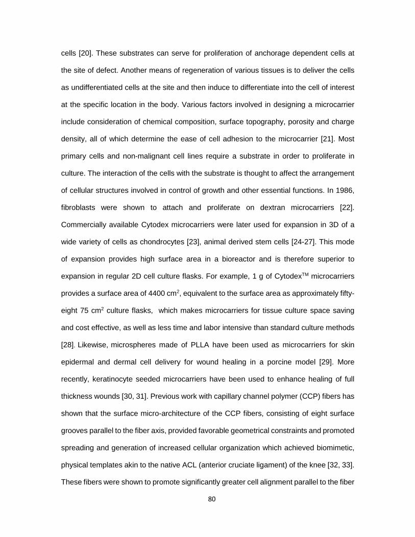
cells [20]. These substrates can serve for proliferation of anchorage dependent cells at
the site of defect. Another means of regeneration of various tissues is to deliver the cells
as undifferentiated cells at the site and then induce to differentiate into the cell of interest
at the specific location in the body. Various factors involved in designing a microcarrier
include consideration of chemical composition, surface topography, porosity and charge
density, all of which determine the ease of cell adhesion to the microcarrier [21]. Most
primary cells and non-malignant cell lines require a substrate in order to proliferate in
culture. The interaction of the cells with the substrate is thought to affect the arrangement
of cellular structures involved in control of growth and other essential functions. In 1986,
fibroblasts were shown to attach and proliferate on dextran microcarriers [22].
Commercially available Cytodex microcarriers were later used for expansion in 3D of a
wide variety of cells as chondrocytes [23], animal derived stem cells [24-27]. This mode
of expansion provides high surface area in a bioreactor and is therefore superior to
expansion in regular 2D cell culture flasks. For example, 1 g of CytodexTM microcarriers
provides a surface area of 4400 cm2, equivalent to the surface area as approximately fifty-
eight 75 cm2 culture flasks, which makes microcarriers for tissue culture space saving
and cost effective, as well as less time and labor intensive than standard culture methods
[28]. Likewise, microspheres made of PLLA have been used as microcarriers for skin
epidermal and dermal cell delivery for wound healing in a porcine model [29]. More
recently, keratinocyte seeded microcarriers have been used to enhance healing of full
thickness wounds [30, 31]. Previous work with capillary channel polymer (CCP) fibers has
shown that the surface micro-architecture of the CCP fibers, consisting of eight surface
grooves parallel to the fiber axis, provided favorable geometrical constraints and promoted
spreading and generation of increased cellular organization which achieved biomimetic,
physical templates akin to the native ACL (anterior cruciate ligament) of the knee [32, 33].
These fibers were shown to promote significantly greater cell alignment parallel to the fiber
80

axis and organized ECM deposition than round fiber controls of comparable denier or
perimeter. In this study, we demonstrated the development of an injectable fiber-based
microcarrier for tissue regeneration. Gel-based composite systems have been shown to
provide physical support for cellular focal adhesion while also facilitating cell spreading
phenotype [34]. Gelatin grafted gellan (TriG) microspheres have been used as cell-laden
microcarriers for hMSCs which upon encapsulation within agarose gel demonstrated two
fold increase in cell proliferation compared to gel only controls [34]. The composite
developed in this study is a photocrosslinked, hybrid semi-interpenetrating polymer
network (semi-IPN) composed of synthetic polyethylene glycol diacrylate (PEGdA), native
hyaluronic acid (HA), and the integrin binding peptide GRGDS with dispersed cell carrying
CCP polylactide (PLA) staples sized approx. 180 µm. The results of these studies
demonstrate that fibroblasts pre-seeded on CCP-based microcarriers exhibit significantly
increased cell proliferation with PEGdA/HA semi-IPNs relative to bulk-encapsulated cells
without microcarriers.
MATERIALS AND METHODS
Capillary channel polymer fiber staple fabrication and characterization
Capillary channel polymer (CCP) fibers were melt extruded from polylactide (PLA,
Natureworks) as previously described [32]. Briefly, an extruder with a 30 hole custom
spinneret was used to produce CCP fibers at an extrusion temperature of 240 °C, flow
rate of 8.76 cc/min and take up speed of 270 m/min. CCP fibers were embedded in
Optimal Cutting Temperature (OCT) compound and cut on a cryostat microtome (Microm
HM 505 N). The OCT slices were collected in a 50 ml tube and washed three times (1
81

hr/wash) by sonication in distilled water (Model 75D, VWR International, West Chester,
PA). After each wash, the staples were centrifuged (Accuspin 1R, Fisher Scientific) at
6000 rpm for 10 minutes and the supernatant discarded and replaced. The complete
removal of OCT from the staples was verified by ATR-FTIR (Thremo-Nicolet Magna 550
FTIR spectrometer equipped with a Thermo-SpectraTech Endurance Foundation Series
Diamond ATR). The staples were then recovered by lyophilization (Freezone 4.5,
Labconco). For SEM imaging, the samples were placed on glass cover slips mounted on
stainless steel SEM stubs, coated with platinum and imaged with a Hitachi S-4800 high
resolution scanning electron microscope at 10 kV image beam intensity (Fig.3.2). The
staples were also imaged by phase contrast microscopy and their size was measured
using ImagePro (Media Cybernetics, Rockville, MD) software.
Cell culture and seeding on staples
Mouse-derived NIH3T3 fibroblasts (ATCC® CRL-1658) were cultured in 75cm2
tissue culture flasks with DMEM/F-12 50:50 1X media (Mediatech, Herdon, VA)
supplemented with 10% (v/v) bovine growth serum (Hyclone, Logan UT), and 50 U/mL
penicillin and 50 µg/mL streptomycin (Mediatech). Medium was changed every 2 days and
cells were maintained in a tissue culture incubator at 37⁰C with 5% carbon dioxide (CO2).
In order to improve cell adhesion, the staples were incubated with fibronectin
(20µg/ml, F1141-5MG, Sigma) in a micro-centrifuge tube overnight at room temperature
attached to a rotary cell culture system (Synthecon Inc., Houston, Texas) rotating at 15
rpm and then washed with 1X PBS. FN-coated staples (15mg) were seeded with 1x10⁶
cells in 1 ml medium in a 1.5 ml micro-centrifuge tube and incubated on a rotary platform
(15 rpm) housed in a cell culture incubator for 6 hr. The staples were allowed to settle and
the supernatant was discarded. The cell-seeded staples were then transferred to a 24 well
plate at 7.5 mg per well and incubated for 42 hours. This method allowed any remaining
82

non-adherent cells to be removed by attachment to the bottom of the well. The seeding
efficiency on the CCP staples was assessed by viability staining at 48 hrs (Calcein AM,
Life Technologies, Carlsbad, CA). To evaluate cell morphology and cytoskeletal
organization, cells were fixed in 4% paraformaldehyde for 1 hour, permeabilized with 0.1%
Triton X-100, and stained with Alexa 594-phalloidin and DAPI (Life Technologies).
Fluorescence images were captured using an AMG EVOS microscope (Fisher Scientific,
Pittsburgh, PA). For SEM imaging, cell-seeded staples were fixed in paraformaldehyde,
dehydrated in a series of ethanol washes, immersed in hexamethyldisilazane (United
Chemical Technologies, Bristol, PA) and air dried on glass cover slips at room temperature
overnight in fume hood. The samples were then mounted on stainless steel SEM stubs,
coated with platinum, and imaged at 10 kV image beam intensity (Hitachi S-4800).
Fig.4.1. Schematic of 3T3 fibroblast cell seeding and culture in 3D hydrogel composites.
Photocrosslinking
Fibronectin coated
CCP staple
3T3 fibroblasts
Encapsulation in PEGdA hydrogel
83

Validation of injectability
CCP staples were seeded with NIH 3T3 fibroblasts as described above. At 48
hours post-seeding, staples were suspended in medium (10 mg/ml) and passed through
a 21G syringe needle (Becton Dickinson, Franklin Lakes, NJ) to validate their injectability
and investigate the effect of injection on cell viability. Cells were stained with Calcein AM
and compared to non-injected controls.
Synthesis of PEG-DA macromers with ester linkages containing variable alkyl
spacers
Three different types of PEG-DA macromers with varying susceptibility to
hydrolytic degradation were synthesized by a two-step process as previously reported
[32]. Briefly, PEG (4000 MW, Fluka, Buchs, Switzerland) was reacted with either
choroacetyl chloride, 2-chloropropionyl chloride, or 4-chlorobutuyrl chloride (Sigma-
Aldrich, St. Louis, MO) in the presence of triethylamine (TEA, Sigma-Aldrich) at a 1:4:1.8
molar ratio in dry dichloromethane (Sigma-Aldrich). After 24 hrs reaction at room
temperature, the reactants were filtered, washed with sodium bicarbonate and water, dried
with anhydrous sodium sulfate, and then precipitated in ethyl ether. After recovery, each
resulting intermediate product was reacted with sodium acrylate (5X molar ratio) in dry
dimethylformamide (Acros, Morris Plains, NJ) for 30 hours at 50, 85, and 100 ⁰C to yield
PEG-bis (acryloyloxy acetate) [PEG-bis-AA], PEG-bis-(acryloyloxy propanoate) [PEG-bis-
AP] and PEG-bis-(acryloyloxy butyrate) [PEG-bis-AB], respectively. The products were
purified by filtration, rotary evaporation, and precipitation in ethyl ether and dried under
vacuum. The structures of each PEGdA and the degree of acrylation were determined
84

from the 1H-NMR (Brucker 300MHz, CDCl3) spectra. All samples achieved acrylation
efficiencies greater than 90%.
Preparation of staple-hydrogel composites
HA (2% w/v, 1.5 MDa, LifeCore Biomedical, Chaska, MN) and PEG-DA (30% w/v)
stock solutions were prepared in 1X-PBS (0.1M, pH 7.4). Acryl-PEG-GRGDS was
synthesized by conjugating GRGDS peptide (Bachem, Torrance, CA) to acryl-PEG-NHS
(Jenkem, Beijing, China) as previously described [35]. Gel precursor solutions were
prepared containing PEG-DA (6% w/v), HA (0.36% w/v 1.5 MDa), acryl-PEG-GRGDS
(1 mol/mL), 2-hydroxy-1-[4-(hydroxyethoxy) phenyl]-2-methyl-1-propanone (I-2959,
BASF, Florham Park, NJ, 0.1% w/v), and cell seeded staples (5 mg/ml). Sample volumes
(45 µl) were pipetted in between glass coverslips separated by 1 mm Teflon spacers and
exposed to low intensity UV light (365nm, 10mW/cm2, Black-Ray B100-AO, Upland, CA)
for 5 minutes on each side of the disc. Hydrogels with encapsulated staples were cultured
in Petri dishes (Becton Dickinson, San Jose, CA) with 2mL culture medium. As a control,
hydrogels with the same composition were prepared with cells only and no staples. Gels
(n=7 samples / group) were cultured for 21 days.
Confocal imaging
The viability of encapsulated cells was determined by vital staining using Calcein
AM/ethidium bromide at 1, 7, 14, and 21 days post-encapsulation. Gel samples were
placed in glass-bottom well chambers (Lab-Tek, Hatfield, PA) for imaging. Images of
stained cells were captured via confocal laser scanning microscopy (Ti-Eclipse, Nikon,
Tokyo, Japan). Cell morphology inside hydrogel was visualized and compared to assess
85

cell spreading and proliferation. The region of interest in the gel sample was identified and
the system software was programmed to collect images at 20 µm intervals through the
thickness of the gel (z-dimension). Macroscopic images of sample hydrogels were also
captured alongside with an iphone 5 (Apple).
Cell proliferation
At 1, 7, 14, and 21 days post encapsulation, gel samples (n=5 gels/group) were
homogenized in 0.1% Triton-x and stored at -80 ⁰C until ready for assay. The samples
were thawed and homogenized using probe sonication (10W for 1 minute, Omni-Raptor
4000, OMNI International Inc.) on ice followed by centrifugation and collection of the
supernatant. The DNA content in each gel sample was then determined by PicoGreen
double stranded assay (Life Technologies, Carlsbad, CA). Gels containing cells without
staple microcarriers were used as control and gels without any cells were used as blanks.
Serial dilution of 3T3 fibroblasts at known concentration was used to generate a standard
curve. Samples were analyzed according to the manufacturer’s instructions, using a
Synergy H1 hybrid fluorometer (Bio-Tek, Winooski, VT) at 480 nm excitation and 520 nm
emission wavelengths.
Statistical analysis
Quantitative data for cell proliferation were compared by ANOVA using Tukey’s
method for post-hoc comparisons (one-way ANOVA). p values < 0.05 were considered to
be statistically significant. All quantitative data are presented as mean ± standard error of
the mean.
86

RESULTS:
Preparation of CCP staples
CCP fibers were melt extruded using a customized spinneret as previously
described in Chapter 3. We used group B of the various CCP fiber samples described in
the Table 1 in Chapter 3. The fibers were imaged by a microscope and found to have the
following groove dimensions- major groove width (25±1.37) µm, major groove depth
(34±1) µm, minor groove width (14.8±1.08) µm, minor groove depth (15.67±.75) µm. The
average length of staples made from these fibers was found to be 184.8±11µm. The
staples were imaged by SEM (Fig.4.2).
Fig.4.2. SEM image of CCP staples (x400)
87

Cell culture and seeding on staples
Cells were found to be efficiently seeded in the grooves of the CCP staples after 6
hour rotary followed by 42 hour static seeding. The adhered cells were seen to spread in
the grooves by actin/DAPI staining which clearly illustrates the polarization of the cell
nuclei and cytoskeleton (Fig.4.3a). Also the filopodial projections could be observed by
SEM imaging (Fig.4.3b). This combined method of rotary and static seeding enabled more
uniform distribution of cells on the staples as opposed to just static seeding. In addition,
any excess cells non adherent to the staples would adhere to the well bottom and allowed
them to be screened away from the cells adhered to the staples.
Fig.4.3. 3T3 cells on CCP staples after 48 hours in culture (a). Actin filaments (green) and nuclei (blue) indicate spread of cells inside the staple grooves (b). SEM image showing filopodial projections on staple
Validation of injectability
Staple injectability was tested by injecting CCP staples through 21G needle at
concentration of 5mg/ml. Viable adherent cells were stained with Calcein AM before
passing through the injection needle. Images were taken before and after the injectability
a b
88

test. It was found that staples retained viable cells when passed through 21 gauge needle
(Fig.4.4).
Fig.4.4. Injectability of CCP seeded 3T3 fibroblasts stained live with Calcein AM (a).before and (b). after injection through 21G needle (Scale bar = 400 um)
Cell-staple encapsulation and growth within hydrogel composites
Cell adhesion and proliferation are crucial to designing scaffolds for tissue
engineering [36]. In order to employ the microengineered 3D hydrogel-staple composites
for tissue engineering applications, encapsulated cells must demonstrate viability and
proliferation over time. We encapsulated NIH3T3 fibroblasts as a model cell line in this
study. Hydrogel composite semi-IPNs were made by blending PEG-DA macromers,
hyaluronic acid and GRGDS-acrylate with CCP staples to investigate the effect of staples
as microcarriers for cell growth and proliferation. Gels without staples were used as
controls. Each gel contained approximately 225 µg of staples and 69000 cells.
We compared the response of round fiber cross-section staples using the same
hydrogel composite system, but cells would aggregate the round staples and prevent
homogeneous distribution in the bulk of the hydrogel during crosslinking. The CCP
a b
89

counterpart, allows the staples to remain non-aggregated and separated during
photocrosslinking (Fig.4.5).
Fig.4.5. Cell adhesion to staples 48 hours post seeding (a). Round cross-section staples show aggregate formation (b). CCP cross-section staples show no aggregation and well dispersed. (Scale bar 400um, Magnification 10x, Green = Calcein AM live stain)
Cell growth in the hydrogel composites was qualitatively observed by laser
confocal microscopy. Live cell staining showed that the fibroblasts in hydrogel composites
were highly viable and proliferating with time during the culture (Fig.4.6). At Day 10,
conspicuous signs of increased cell number could be observed with the staples at the core
of expanding cell colonies. From day 14 onwards, the cell colonies merged to form high
cell density areas as compared to the control gels. The control gels without staples
demonstrated round but viable cells over 3 weeks (Fig.4.7). These cells did not exhibit any
form of spreading or proliferation but formed aggregates that would exude out of the gel
periphery at Day 21. The observations from laser confocal imaging were also be
corroborated by macroscopic imaging as shown in Figs. 4.6 & 4.7. 3D rendering of the cell
behavior comparison in composite and control gels is also shown at Day 1 and Day 21
time points in Fig. 4.8.
a b
90

Fig.4.6. Fluorescent images of live 3T3 fibroblasts grown in hydrogel composites (PEGdA/HA/PLA staples). Cell seeded staple encapsulation density was 5 mg ml-1. 3T3 fibroblasts were labeled with live cell stain Calcein AM. [Scale bar on columns denotes- left 1 cm, right 200µm]
f
Day 1
Day 7
Day 10
Day 14
Day 18
Day 21
91
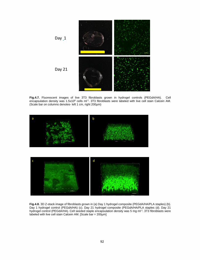
Fig.4.7. Fluorescent images of live 3T3 fibroblasts grown in hydrogel controls (PEGdA/HA). Cell encapsulation density was 1.5x10⁶ cells ml-1. 3T3 fibroblasts were labeled with live cell stain Calcein AM. (Scale bar on columns denotes- left 1 cm, right 200µm)
Fig.4.8. 3D Z-stack image of fibroblasts grown in (a) Day 1 hydrogel composite (PEGdA/HA/PLA staples) (b). Day 1 hydrogel control (PEGdA/HA) (c). Day 21 hydrogel composite (PEGdA/HA/PLA staples (d). Day 21 hydrogel control (PEGdA/HA). Cell seeded staple encapsulation density was 5 mg ml-1. 3T3 fibroblasts were labeled with live cell stain Calcein AM. [Scale bar = 200µm]
a b
c d
Day 1
Day 21
92

In addition to qualitative determination of cell proliferation in the 3D composite
gels using confocal imaging, we also quantified the proliferation using Picogreen assay
for ds-DNA. The composite hydrogels demonstrated increase in cell number by almost
ten-fold by Day 21 when compared to Day 1. No significant difference in cell proliferation
was observed among the controls after 21 days (Fig.4.9).
Fig.4.9. Proliferation of NIH3T3 fibroblasts in hydrogel composites (PEGdA/HA/Staples) and PEGdA/HA controls. Cells were encapsulated at 1.5x10⁶ cells ml-1. Cell number was determined by Picogreen assay for DNA. One way ANOVA revealed differences between Day 1 and Day 21 for the composite gels (p<0.05, * vs Day 1 composite, # vs Day 1 control)
0
2
4
6
8
10
12
1 7 14 21
Cel
l Num
ber
norm
aliz
ed to
Day
1
Time (Days)
with staples
withoutstaples
*#
#
#
93

DISCUSSION:
In this manuscript, the use of PEGdA/HA-CCP staple composite hydrogel system
for cell culture and tissue engineering applications has been demonstrated. PEGdA
hydrogels were blended with hyaluronic acid (HA) and cell adhesion motif peptide
GRGDS-acrylate. Signals from RGD sequences induce direct and specific α5β1 integrin
binding [37] and cells form focal contacts at the integrin-binding sites by synthesizing focal
adhesion proteins (namely vinculin, paxillin, talin) that in turn connect to cytoskeletons
[38].
The gels were mixed with cell laden microcarrier CCP staples and
photocrosslinked. The hydrogel composite showed excellent cell proliferation as
compared to control gels. The microcarrier based composite offers a unique method for
cell amplification at site of defect in situ by serving as substrates for the propagation of
anchorage-dependent cells. A composite integrating the microcarriers inside a hydrogel
can not only provide a suitable platform for cellular focal adhesion but in addition facilitates
the cells to overcome gel enlacement and fully spread out into their natural morphology
[34]. This system can be translatable into delivery of expanded culture of undifferentiated
or differentiated cells. The encapsulation of the microcarriers within biocompatible and
injectable hydrogels enhances the viability of cells at the repair site. For instance,
angiogenesis was demonstrated when endothelial cell laden gelatin coated Cytodex-3
microcarriers were entrapped in three dimensional fibrin matrix with fibronectin, basic
fibroblast growth factor (bFGF) and vascular endothelial growth factor (VEGF) [39]. It was
shown that mere proliferation and migration was not essential for capillary formation, but
that inter-cellular adhesion was a crucial factor for efficient neovessel formation. Apart
94

from promoting intercellular attachment, encapsulation within a matrix can lend a
protective and trophic environment for the cells to endure shear forces during injection
delivery to the defect site.
One step further would be the development of microcarriers which allow the cells
to maintain their natural phenotype. It is widely accepted that the phenotype of cells in
two-dimension culture is very different from their behavior in three dimensions [40]. Micro
and nano sized scale features can be used to mimic the natural ECM microenvironment
of tissues [41]. To that end, we were interested in exploring the role of topographical
features on cell adhesion, polarization and proliferation for various tissue engineering
applications. In this work, we studied the effect of a uniquely designed capillary channel
polymer (CCP) fiber staples and its topographic effect on cell polarization and proliferation
inside a synthetic hydrogel. The staples were coated with fibronectin for aiding the
adhesion of fibroblasts, in addition the presence of cross-linked peptide cell adhesion motif
GRGDS in the bulk of the hydrogel also helps the cells to interact with the otherwise
synthetic matrix by integrin binding.
Nanofibrous polyglycerol sebacate (PGS) staples have been explored by
Ravichandran et al for injectable cardiomyocytes delivery within an infarct [42]. They
observed that the morphology of the short fiber staples was retained after passing through
an 18G needle. These fibers were of length 3.8 µm and diameter of 1 µm. However, they
did not show how cell laden short fibers would respond to passage through the injection
needle. In our work, we have explored the viability of CCP fiber staples in the micron –
size range – length ~180µm and diameter ~50 µm with cells adhering and retaining
viability and remaining adherent to the staples even upon passing through 21G needle.
The cells in the control gels did not show any proliferation over 3 weeks which
supports our hypothesis that physical topographic support plays an important role in cell
95

proliferation. This NIH3T3 cell response in control gels is contrary to normal human dermal
fibroblast (NHDF) response when encapsulated in PEGdA/HA blend gels [16] wherein 1.5
fold proliferation was recorded in 14 days compared to Day 1. This is consistent with Shu
et al, who also showed 1.5 times increase in T-31 fibroblast after 15 days culture inside
the HA-DTPH-PEGdA hydrogel [43]. In our work, we were able to demonstrate 10 fold
increase in cell number in hydrogel composite samples over 3 weeks by Picogreen assay
which quantifies the increase in double stranded DNA (dsDNA). The importance of
physical support in the form of microcarriers is corroborated by the fact that no increase
in cell number was observed in the control gels (Fig.4.9).
The isotropic nature of the hydrogels can be overcome by integrating topographic
structures to induce anisotropy and cell polarization. The resulting composite could
topographically mimic the ECM to control cell adhesion, morphology and tissue
architecture. In the composite gels developed in this work, the presence of physical
topographic support by the CCP staples perhaps orients the cell cytoskeleton in a manner
which induces higher ECM production and hence proliferation [44-46]. Substratum
topography can serve as a means of manipulating cell function because surfaces provide
a two-pronged biomimetic extracellular physical milieu and cell stimulating cue.
Of special long term interest to us is the ability to induce adhesion, polarization
and thereby differentiation of neural stem cells in an injectable hydrogel system for neural
regeneration purposes. This is because for stem cells, the ability to control and regulate
cell proliferation in 3D is crucial for cell differentiation fate and proliferation. Using the
composite system developed in this work, we can expand NSCs in three dimensions in
the bulk by contact with the staples followed by induction of differentiation.
96

CONCLUSION:
A biodegradable hydrogel-fibrous staple composite demonstrating sustained cell
survival and proliferation was developed. 3T3 fibroblasts pre-seeded on CCP staples
when encapsulated in PEGdA/HA hydrogel blends, showed high proliferation as
compared to control gels without CCP staple microcarriers. The physical properties of the
composite system demonstrated cell cluster formation around the staples in 3D by
proliferation. This study indicated that the hydrogel-staple composite may have promising
potential in various tissue regeneration applications involving stem cell proliferation and
differentiation. Future studies could include incorporation of neural stem cells to induce
differentiation into neural lineage for targeting CNS trauma and neurodegenerative
disease.
97

References:
[1] Rutkowski G, Miller CA, Mallapragada S. Processing of polymer scaffolds: solvent casting. Academic Press, San Diego, CA; 2002. p. 681-6.
[2] ON EME. Bone marrow cell colonization of, and extracellular matrix expression on, biodegradable polymers. Cells and Materials 1997;7:223-34.
[3] Harris LD, Kim B-S, Mooney DJ. Open pore biodegradable matrices formed with gas foaming. 1998.
[4] Hall H. Modified fibrin hydrogel matrices: both, 3D-scaffolds and local and controlled release systems to stimulate angiogenesis. Current pharmaceutical design 2007;13:3597-607.
[5] Cai S, Liu Y, Zheng Shu X, Prestwich GD. Injectable glycosaminoglycan hydrogels for controlled release of human basic fibroblast growth factor. Biomaterials 2005;26:6054-67.
[6] Pack DW, Hoffman AS, Pun S, Stayton PS. Design and development of polymers for gene delivery. Nature Reviews Drug Discovery 2005;4:581-93.
[7] Norman JJ, Desai TA. Methods for fabrication of nanoscale topography for tissue engineering scaffolds. Annals of biomedical engineering 2006;34:89-101.
[8] Kim EJ, Boehm CA, Mata A, Fleischman AJ, Muschler GF, Roy S. Post microtextures accelerate cell proliferation and osteogenesis. Acta biomaterialia 2010;6:160-9.
[9] Yang J-H, Lin S-H, Lee Y-D. Preparation and characterization of poly (l-lactide)–graphene composites using the in situ ring-opening polymerization of PLLA with graphene as the initiator. Journal of Materials Chemistry 2012;22:10805-15.
[10] Carlberg B, Axell MZ, Nannmark U, Liu J, Kuhn HG. Electrospun polyurethane scaffolds for proliferation and neuronal differentiation of human embryonic stem cells. Biomedical Materials 2009;4:045004.
[11] Xie J, Willerth SM, Li X, Macewan MR, Rader A, Sakiyama-Elbert SE, et al. The differentiation of embryonic stem cells seeded on electrospun nanofibers into neural lineages. Biomaterials 2009;30:354-62.
[12] Lim SH, Liu XY, Song H, Yarema KJ, Mao H-Q. The effect of nanofiber-guided cell alignment on the preferential differentiation of neural stem cells. Biomaterials 2010;31:9031-9.
[13] Lee KY, Mooney DJ. Hydrogels for tissue engineering. Chemical reviews 2001;101:1869-80.
[14] Davis HE, Leach JK. Hybrid and Composite Biomaterials in Tissue Engineering. Topics in multifunctional biomaterials and devices 2008.
[15] Jia X, Kiick KL. Hybrid multicomponent hydrogels for tissue engineering. Macromolecular bioscience 2009;9:140-56.
[16] Kutty JK, Cho E, Soo Lee J, Vyavahare NR, Webb K. The effect of hyaluronic acid incorporation on fibroblast spreading and proliferation within PEG-diacrylate based semi-interpenetrating networks. Biomaterials 2007;28:4928-38.
98

[17] Zhu J. Bioactive modification of poly (ethylene glycol) hydrogels for tissue engineering. Biomaterials 2010;31:4639-56.
[18] Almany L, Seliktar D. Biosynthetic hydrogel scaffolds made from fibrinogen and polyethylene glycol for 3D cell cultures. Biomaterials 2005;26:2467-77.
[19] Ifkovits JL, Burdick JA. Review: photopolymerizable and degradable biomaterials for tissue engineering applications. Tissue engineering 2007;13:2369-85.
[20] Van Wezel A. Growth of cell-strains and primary cells on micro-carriers in homogeneous culture. Nature 1967;216:64-5.
[21] Malda J, Frondoza CG. Microcarriers in the engineering of cartilage and bone. Trends in biotechnology 2006;24:299-304.
[22] Varani J, Bendelow MJ, Chun JH, Hillegas WA. Cell growth on microcarriers: comparison of proliferation on and recovery from various substrates. Journal of biological standardization 1986;14:331-6.
[23] Malda J, Van Blitterswijk C, Grojec M, Martens D, Tramper J, Riesle J. Expansion of bovine chondrocytes on microcarriers enhances redifferentiation. Tissue engineering 2003;9:939-48.
[24] Abranches E, Bekman E, Henrique D, Cabral J. Expansion of mouse embryonic stem cells on microcarriers. Biotechnology and bioengineering 2007;96:1211-21.
[25] Fernandes A, Fernandes T, Diogo M, da Silva CL, Henrique D, Cabral J. Mouse embryonic stem cell expansion in a microcarrier-based stirred culture system. Journal of biotechnology 2007;132:227-36.
[26] Yang Y, Rossi F, Putnins EE. Ex vivo expansion of rat bone marrow mesenchymal stromal cells on microcarrier beads in spin culture. Biomaterials 2007;28:3110-20.
[27] Frauenschuh S, Reichmann E, Ibold Y, Goetz PM, Sittinger M, Ringe J. A Microcarrier‐Based Cultivation System for Expansion of Primary Mesenchymal Stem Cells. Biotechnology progress 2007;23:187-93.
[28] Cytodex Surface Microcarriers GE Healthcare Biosciences AB. p. Cytodex Surface Microcarriers.
[29] Lafrance ML, Armstrong DW. Novel living skin replacement biotherapy approach for wounded skin tissues. Tissue engineering 1999;5:153-70.
[30] Voigt M, Schauer M, Schaefer D, Andree C, Horch R, Stark G. Cultured epidermal keratinocytes on a microspherical transport system are feasible to reconstitute the epidermis in full-thickness wounds. Tissue engineering 1999;5:563-72.
[31] Bayram Y, Deveci M, Imirzalioglu N, Soysal Y, Sengezer M. The cell based dressing with living allogenic keratinocytes in the treatment of foot ulcers: a case study. British journal of plastic surgery 2005;58:988-96.
[32] Sinclair KD, Webb C, Brown PJ. Capillary channel polymer fibers as structural templates for ligament regeneration. Am Assoc Text Chem Colorists 2008;8:36-40.
99

[33] Sinclair KD, Webb K, Brown PJ. The effect of various denier capillary channel polymer fibers on the alignment of NHDF cells and type I collagen. Journal of Biomedical Materials Research Part A 2010;95:1194-202.
[34] Wang C, Gong Y, Zhong Y, Yao Y, Su K, Wang D-A. The control of anchorage-dependent cell behavior within a hydrogel/microcarrier system in an osteogenic model. Biomaterials 2009;30:2259-69.
[35] Hern DL, Hubbell JA. Incorporation of adhesion peptides into nonadhesive hydrogels useful for tissue resurfacing. Journal of biomedical materials research 1998;39:266-76.
[36] Khademhosseini A, Vacanti JP, Langer R. Progress in tissue engineering. Scientific American 2009;300:64-71.
[37] Chien H-W, Tsai W-B. Fabrication of tunable micropatterned substrates for cell patterning via microcontact printing of polydopamine with poly (ethylene imine)-grafted copolymers. Acta biomaterialia 2012;8:3678-86.
[38] Ventre M, Causa F, Netti PA. Determinants of cell–material crosstalk at the interface: towards engineering of cell instructive materials. Journal of The Royal Society Interface 2012;9:2017-32.
[39] Nehls V, Drenckhahn D. A novel, microcarrier-based in vitro assay for rapid and reliable quantification of three-dimensional cell migration and angiogenesis. Microvascular research 1995;50:311-22.
[40] Nehls V, Schuchardt E, Drenckhahn D. The effect of fibroblasts, vascular smooth muscle cells, and pericytes on sprout formation of endothelial cells in a fibrin gel angiogenesis system. Microvascular research 1994;48:349-63.
[41] Murugan R, Ramakrishna S. Nano-featured scaffolds for tissue engineering: a review of spinning methodologies. Tissue engineering 2006;12:435-47.
[42] Ravichandran R, Venugopal JR, Sundarrajan S, Mukherjee S, Sridhar R, Ramakrishna S. Minimally invasive injectable short nanofibers of poly (glycerol sebacate) for cardiac tissue engineering. Nanotechnology 2012;23:385102.
[43] Shu XZ, Ghosh K, Liu Y, Palumbo FS, Luo Y, Clark RA, et al. Attachment and spreading of fibroblasts on an RGD peptide–modified injectable hyaluronan hydrogel. Journal of Biomedical Materials Research Part A 2004;68:365-75.
[44] Lee CH, Shin HJ, Cho IH, Kang Y-M, Kim I, Park K-D, et al. Nanofiber alignment and direction of mechanical strain affect the ECM production of human ACL fibroblast. Biomaterials 2005;26:1261-70.
[45] Zhong S, Teo WE, Zhu X, Beuerman RW, Ramakrishna S, Yung LYL. An aligned nanofibrous collagen scaffold by electrospinning and its effects on in vitro fibroblast culture. Journal of biomedical materials research Part A 2006;79:456-63.
[46] Bashur CA, Dahlgren LA, Goldstein AS. Effect of fiber diameter and orientation on fibroblast morphology and proliferation on electrospun poly (d, l-lactic- co-glycolic acid) meshes. Biomaterials 2006;27:5681-8.
100

CHAPTER 5
ENGINEERING STEM CELL FATE USING COMPOSITE SCAFFOLD
INTRODUCTION:
Biodegradable scaffolds provide a temporal structural support for transplanted stem
cells. In addition, the scaffold also delivers bioactive signals for stem cell differentiation,
either in the form of released/immobilized trophic factors or through topographic
microarchitecture and appropriate biomechanical properties. However, the nervous tissue
is extremely complicated. It starts off as the neural plate - a flat sheet of cells on the top
surface of the embryo, and undergoes a series of elaborate deformations, resulting in
morphogenetic transformation into a hollow tube [1]. One end of this neural tube eventually
forms the brain and the other end forms the spinal cord. This complex formation of the
nervous system makes it difficult to design an intricate scaffold that would simulate the
growth of nervous tissue. While stem cell therapy is a viable option for CNS treatments,
many challenges need to be addressed including low cell survival, lack of control on stem
cell fate and low cell engraftment and integration with existing neuronal circuitry after
transplantation [3]. Though overcoming these obstacles is challenging, the design of
structures that mimic the native stem cell niches for transplanted cells can be promising.
So, the need to develop a suitable cell laden scaffold which can serve as a cell proliferation
platform and also induce differentiation at the transplant site is substantial.
NSCs are self-renewing, multipotent stem cell populations that are present in both
the developing and adult mammalian CNS [3]. They are responsible for generating
neurons and glia in developing brain and so play a key role in augmenting the otherwise
limited ability of the adult CNS to regenerate after injury or disease [4]. NSCs exist as
neuroepithelial stem cells in the embryonic neural tube. When the tube undergoes
101

symmetric division, the NSCs exist as radial glia cells and begin to generate neuronal
lineages by asymmetrically dividing within the germinal ventricular zone (GVZ). NSCs then
acquire gliogenic competency and produce glial progenitor cells, which proliferate mostly
in a second germinal or subventricular zone (SVZ) – located along the lateral wall of the
lateral ventricle [5]. By the postnatal stage, most of the radial glia transform into astrocytes
and the ventricular zone disappears. Some portion of the SVZ is retained in the adult CNS
and serves as one of the primary sites for neurogenesis [6]. These sites are highly
significant when considering neural tissue engineering approaches. Two approaches can
be considered for NSC mediated regeneration – activation of endogenous stem cells or
transplantation of neural stem cells [7, 8]. The regenerative capacity of the endogenous
stem cells is very low since they are unable to reconstitute the structural architecture of
the CNS.
Transplantation of NSCs is a more promising approach for CNS regeneration
although the fate of transplanted cells is determined by the type of injury/disease and the
biochemical and biomechanical microenvironment at the site [8]. The hostile environment
at the site affects the survival and functionality of the transplanted cells [9]. Rather than
direct injection, the creation of the physiological stem cell niche is a more efficient
approach [10]. This niche should be a specialized conglomerate providing the correct
architecture and containing the required biochemical cytokines/growth factors and signals
apart from the right biomechanical properties of native environment [11]. These
requirements are important to consider in the development of a biomaterial to mimic the
microenvironment [12, 13]. A variety of biomaterials such as hydrogels and nanofibers
have been explored towards this end. Hydrogels are of particular interest in this case
because of their close resemblance to soft tissues, owing to their cross-linked hydrophilic
polymer network. The crosslink density of the polymer network can be tuned to match the
102

mechanical properties of the CNS tissue. Also, hydrogels are injectable and in situ
crosslinkable, which makes them a minimally invasive and defect conforming scaffold.
Hydrogels can assist in angiogenesis, prevent immune response and inhibit glial scarring
as well. However, hydrogels are isotropic and may not strictly control the differentiation
fate of NSCs as desired. The fate can be specified by inducing the cells towards a
morphological shape that would facilitate their differentiation by cytoskeletal
rearrangement of actin filaments and focal adhesion complexes, thus bringing about a
signal transduction from the extrinsic mechanical signaling to intrinsic intracellular
signaling [14, 15].
The differentiation response of NSCs to surface topography has been widely
studied. Aligned nanofibers exhibited higher differentiation into neurons as compared to
random counterpart and planar control [16]. Bakhru et al showed that NSCs adhered on
and in close proximity to aligned fibers showed more differentiation inclination towards
neuronal lineage while cells further away from the fibers differentiated into astrocytes [17].
They also showed that the differentiation into neurons was induced in cells not
immediately on fibers by paracrine signaling from cells on the fibers. Hseih et al developed
a composite gel-fiber scaffold made of hyaluronan-methylcellulose (HAMC) and
polycaprolactone-co-D,L-lactide [P(CL:DLLA)] that induced higher differentiation into
neurons and oligodendrocytes than HAMC itself [18].
The process of differentiation into neuronal lineage is not straightforward. The
architecture and topography of the scaffold alone does not promote differentiation; so the
media is supplemented with chemical inducers that stem the process of cell proliferation
and induce biochemical signaling pathways that result in differentiation. Retinoic acid is
involved in the induction of neural differentiation, motor axon growth and neural patterning
[19]. Axon outgrowth and nerve regeneration are triggered in adults in response to
103

elevated RA signaling. RA also maintains the differentiated state of adult neurons and
altered RA signaling leads to neurodegenerative diseases as Parkinson’s and Alzheimer’s
disease. RA is a metabolic product of vitamin A (retinol). When retinol binds to retinol-
binding protein 4 (RBP4), it is taken up by cells through a membrane receptor (STRA6)
that interacts with the RBP4. In embryos, retinol dehydrogenase 10 (RDH10) metabolizes
retinol to retinaldehyde (Ral), which is then metabolized to RA by retinaldehyde
dehydrogenases (RALDHs). RA can be released from the cytoplasm and taken up by the
receiving cell (paracrine signaling), or can act back on its own nucleus (autocrine
signaling). Cellular retinoic-acid-binding protein 2 (CRABP2) assists RA entry into the
nucleus. In the nucleus, RA binds to RA receptors (RARs) and retinoid X receptors
(RXRs), which themselves heterodimerize and bind to a sequence of DNA that is known
as the retinoic acid-response element (RARE). This binding activates the transcription of
target genes. RA is catabolized in the cytoplasm by the CYP26 class of P450 enzymes
[19].
104
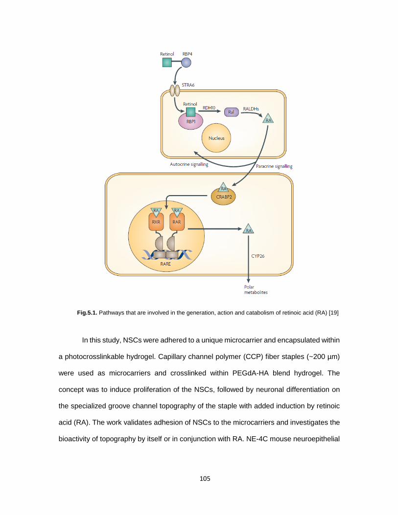
Fig.5.1. Pathways that are involved in the generation, action and catabolism of retinoic acid (RA) [19] In this study, NSCs were adhered to a unique microcarrier and encapsulated within
a photocrosslinkable hydrogel. Capillary channel polymer (CCP) fiber staples (~200 µm)
were used as microcarriers and crosslinked within PEGdA-HA blend hydrogel. The
concept was to induce proliferation of the NSCs, followed by neuronal differentiation on
the specialized groove channel topography of the staple with added induction by retinoic
acid (RA). The work validates adhesion of NSCs to the microcarriers and investigates the
bioactivity of topography by itself or in conjunction with RA. NE-4C mouse neuroepithelial
105

cell lines were chosen for this study. These NSCs have been established to differentiate
into neurons in response to all-trans RA [20].
MATERIALS AND METHODS
Preparation of 2D spin cast samples
Microscopic glass slides were cut with a diamond scribe into 2.5 cm x 1.5 cm pieces
and cleaned with acetone and water and blow dried with compressed air. The slides were
then treated with Piranha solution (3:1 Sulfuric acid : 30% Hydrogen peroxide) and rinsed
thoroughly with distilled water. Poly-l-lactide (PLLA, Natureworks, Minnetonka, MN) was
dissolved at 10% w/v in dichloromethane and spin coated on the glass slides at 2000 rpm
and dried in vacuum for 48 hours to completely remove the dichloromethane. The samples
were physisorbed with either fibronectin (20µg/ml, F1141-5MG, Sigma) or laminin
(20µg/ml, #23017-015, Life technologies, Carlsbad, CA) overnight at room temperature
followed by washing twice with sterile Phosphate Buffer Solution (PBS). For the laminin
samples, polylysine (0.01% in water) was pre-coated on the samples for 1 hour, followed
by washing twice with sterile distilled water, after which laminin or was adsorbed overnight.
For controls, 0.01% polylysine (MW 150000-300000, # P1399-100MG, Sigma) was coated
overnight and washed with distilled water twice. The substrates were incubated in cell
culture media at 37˚C until seeding within one hour.
106

Preparation of fiber samples
Double sided tape was placed on two opposite edges of round glass cover slips
(#26024, Ted Pella, Redding, CA). CCP fibers were aligned and secured between the
taped portions of each coverslip. These samples were sterilized by exposure to UV for 1
hour in 12 well plate. The samples were physisorbed with either 15 µg/ml poly-l-lysine
(MW 150000-300000, # P1399-100MG, Sigma) or fibronectin (20µg/ml, F1141-5MG,
Sigma) overnight at room temperature followed by washing twice with sterile water. The
substrates were incubated in cell culture media at 37˚C until seeding within one hour.
Cell culture and seeding
Mouse-derived NE-4C neuroectodermal cells (ATCC® CRL-2925) were cultured
in poly-l-lysine pre-coated 75cm2 tissue culture flasks with EMEM media (ATCC 30-2003,
Manassas, VA) supplemented with 4mM L-glutamine, 10% (v/v) bovine growth serum
(Hyclone, Logan UT), and 50 U/mL penicillin and 50 µg/mL streptomycin (Mediatech).
Medium was changed every 2 days and cells were maintained in a tissue culture incubator
at 37⁰C with 5% carbon dioxide (CO2).
For cell adhesion, the staples were incubated with poly-l-lysine (15 µg/ml, MW
150000-300000, # P1399-100MG, Sigma) in a micro-centrifuge tube overnight at room
temperature attached to a rotary cell culture system (Synthecon Inc., Houston, Texas)
rotating at 15 rpm and then washed with 1X PBS. PLL-coated staples (15mg) were seeded
with 1x10⁶ cells in 1 ml medium in a 1.5 ml micro-centrifuge tube and incubated on a rotary
platform (15 rpm) housed in a cell culture incubator for 6 hr. The staples were allowed to
settle and the supernatant was discarded. The cell-seeded staples were then transferred
to a 24 well plate at 7.5 mg per well and incubated for 42 hours. This method allowed any
107

remaining non-adherent cells to be removed by attachment to the bottom of the well. The
seeding efficiency on the CCP staples was assessed by SEM imaging at 48 hours (Calcein
AM, Life Technologies, Carlsbad, CA). For SEM imaging, cell-seeded staples were fixed
in paraformaldehyde, dehydrated in a series of ethanol washes, immersed in
hexamethyldisilazane (United Chemical Technologies, Bristol, PA) and air dried on glass
cover slips at room temperature overnight in fume hood. The samples were then mounted
on stainless steel SEM stubs, coated with platinum, and imaged at 10 kV image beam
intensity (Hitachi S-4800).
For 2D polystyrene tissue culture plastic (TCP) or 3D CCP fiber samples, NSCs
were seeded in 12 well cell culture plate at 1.8 x 10⁵ cells/well.
To induce differentiation of NSCs, culture media containing 10-6 retinoic acid (RA)
was administered 48 hours post cell seeding. A10-2 M stock solution of all-trans RA
(Sigma) in dimethylsulfoxide (DMSO) was stored in -80°C. Culture media was changed
every other day and RA supplementation was diluted directly in to the culture medium
whenever fresh medium was added.
Immunostaining of mNSCs
To evaluate cell morphology and cytoskeletal organization, cells were fixed in 4%
paraformaldehyde for 1 hour, permeabilized with 0.1% Triton X-100, and stained with Anti
mouse β-III Tubulin produced in Rabbit (1:500, mouse IgG, Sigma, MO) to identify
neurons. As secondary antibody goat anti-rabbit IgG Alexa 488 (Life Technologies,
Carlsbad, CA) was used at 1:200 dilution in staining media. The nuclei were stained with
108

4’,6-diamidino-2-phenylindole (DAPI, Life Technologies). Fluorescence images were
captured using an AMG EVOS microscope (Fisher Scientific, Pittsburgh, PA).
Synthesis of PEG-dA macromers with ester linkages containing variable alkyl
spacers
Three different types of PEG-DA macromers with varying susceptibility to
hydrolytic degradation were synthesized by a two-step process as previously reported
[32]. Briefly, PEG (4000 MW, Fluka, Buchs, Switzerland) was reacted with either
choroacetyl chloride, 2-chloropropionyl chloride, or 4-chlorobutuyrl chloride (Sigma-
Aldrich, St. Louis, MO) in the presence of triethylamine (TEA, Sigma-Aldrich) at a 1:4:1.8
molar ratio in dry dichloromethane (Sigma-Aldrich). After 24 hours reaction at room
temperature, the reactants were filtered, washed with sodium bicarbonate and water, dried
with anhydrous sodium sulfate, and then precipitated in ethyl ether. After recovery, each
resulting intermediate product was reacted with sodium acrylate (5X molar ratio) in dry
dimethylformamide (Acros, Morris Plains, NJ) for 30 hours at 50, 85, and 100 ⁰C to yield
PEG-bis (acryloyloxy acetate) [PEG-bis-AA], PEG-bis-(acryloyloxy propanoate) [PEG-bis-
AP] and PEG-bis-(acryloyloxy butyrate) [PEG-bis-AB], respectively. The products were
purified by filtration, rotary evaporation, and precipitation in ethyl ether and dried under
vacuum.
Preparation of staple-hydrogel composites
HA (2% w/v, 1.5 MDa, LifeCore Biomedical, Chaska, MN) and PEG-DA (30% w/v)
stock solutions were prepared in 1X-PBS (0.1M, pH 7.4). Acryl-PEG-GRGDS was
synthesized by conjugating GRGDS peptide (Bachem, Torrance, CA) to acryl-PEG-NHS
109

(Jenkem, Beijing, China) as previously described [21]. Gel precursor solutions were
prepared containing PEG-DA (6% w/v), HA (0.36% w/v 1.5 MDa), acryl-PEG-GRGDS
(1 mol/mL), 2-hydroxy-1-[4-(hydroxyethoxy) phenyl]-2-methyl-1-propanone (I-2959,
BASF, Florham Park, NJ, 0.1% w/v), and cell seeded staples (5 mg/ml). Sample volumes
(45 µl) were pipetted in between glass coverslips separated by 1 mm Teflon spacers and
exposed to low intensity UV light (365nm, 10mW/cm2, Black-Ray B100-AO, Upland, CA)
for 5 minutes on each side of the disc. Hydrogels with encapsulated staples were cultured
in 12 well plate wells with 2mL culture medium per well.
RESULTS AND DISCUSSION:
Validation of CCP staple as NSC microcarrier
The seeding efficiency and adherence of NE-4C NSCs to polylysine coated
polylactide staples (~180 µm) using the rotary and static seeding method was validated
by SEM imaging. As can be seen in Fig.5.2, the cells are adhered to the staple and also
extending filopodia.
Fig.5.2. SEM image showing NSCs on CCP staples after 48 hours in culture SEM image
110

Investigation of NSC differentiation
NSCs being anchorage dependent cells, different ligands were tested as effective
adhesion molecule to support the adhesion and growth of NSCs. First, the response of
NSCs on two dimensional polylactide films was investigated, followed by the response on
three dimensional CCP fibers. Polylysine coated tissue culture plates were used as
controls while polylactide films were coated with cell adhesive ligands – fibronectin or
laminin. Laminin was coated in the traditional Polylysine/laminin manner. RA was
administered 24 hours after cell seeding.
Fig.5.3. Fluorescence mages of NSCs polylysine coated TCP (tissue culture plastic) after 8 days of cell culture. For differentiation induction, cells were cultured with 1µM RA (-1/+7) [Green stain = β-III tubulin neuronal marker, Blue stain = DAPI; Scale bar = 400 um]
The controls demonstrated high cell proliferation and aggregate formation when
cultured in absence of RA, while proliferation was reduced by RA administration though
no specific differentiation trend could be recorded in presence of RA (Fig.5.3). Similar to
the polylysine controls, no neuronal differentiation could be observed specifically in
PLL
(+RA)
PLL
(-RA)
111

response to RA induction. Higher cell aggregation and proliferation was observed without
RA (Fig.5.4).
Fig.5.4. Fluorescence mages of NSCs on two dimensional planar polylactide (PLA) films after 8 days of cell culture. For differentiation induction, samples were cultured with 1µM RA (-1/+7) [Green stain = β-III tubulin neuronal marker, Blue stain = DAPI; Scale bar = 400 um]
Fibronectin
(-RA)
Fibronectin
(+RA)
Laminin
(-RA)
Laminin
(+RA)
112

Fig.5.5. Fluorescence mages of NSCs on three dimensional CCP fibers after 8 days of cell culture. For differentiation induction, samples were cultured with 1µM RA (-1/+7) [Green stain = β-III tubulin neuronal marker, Blue stain = DAPI; Scale bar = 400 um]
NSCs were seeded on 3D CCP fiber samples to test for the bioactivity of the
topography with or without RA induction. The result on 3D CCP fibers was similar to the
results on 2D surfaces described earlier. As can be seen in Fig.5.5, some neuronal
differentiation could be seen on CCP fibers without RA administration. Cell proliferation
was drastically reduced upon RA induction, but no neurons could be observed.
PLL
(-RA)
Fibronectin
(-RA)
Fibronectin
(+RA)
113

Discussion:
NE-4C cells are immortalized neuroectodermal progenitor cell line, which have
been established to differentiate into neurons and astrocytes in presence of all-trans
retinoic acid (RA) [20]. However, these cells only differentiate when RA administration is
in concert with formation of adequate intercellular contacts via aggregation [22]. In order
to achieve differentiation, the timing of RA administration appears to be critical, otherwise
cell death occurs owing to the ‘contact lateral inhibition’ phenomenon of these cells.
Various factors such as signaling by the membrane anchored receptor/ligand pair, Notch
and Delta are known to interact to determine the repression or expression of neurogenic
genes, consequently inhibiting or inducing neuronal commitment in NE-4C cells [23].
These facts indicate that gap junctions between these cells communicate signals that
control cell proliferation and differentiation [24, 25].
Schlett et al found that the first neurons appear on the 3rd day after induction and
a dense network of morphologically differentiated neurons develop by the 7th day [20].
However, differentiation into neurons only takes place when RA-treated cell aggregates
are formed, if RA is absent, the cells in the aggregate die. The formation of aggregates
indicated the importance of 3D contacts in neuronal cell fate decision. Cells with astroglial
characteristics appear only by the 10th -12th day of RA induction. These facts indicate that
apart from RA, local biochemical cues are involved during in vitro induction of neuronal
differentiation. Treatment with RA strengthens the cell-to-cell adhesion at the expense of
cell-to-substrate interaction. The appropriate formation of aggregates is also contingent
on the initial cell seeding density, a critical density of 25000 cells/cm2 is necessary for
neuron formation after the initial 24 hours of induction. The importance of paracrine
signaling in neurogenesis was established by blocking gap junction communication with
114

high concentrations of glycyrrethinic acid (GRA) and carbenoxolone (CRX), which highly
reduced rate of neurogenesis in human and mouse cell lines [26].
In this work, RA was administered after 24 hours post cell seeding (-1/+7). When
no significant and specific neuronal differentiation could be observed in response to RA,
some adjustments were made for a new experimental design. For the last experimental
trials (data not shown), the media used was devoid of FBS (fetal bovine serum), the
rationale being that serum withdrawal could encourage differentiation and subdue
proliferation. The experimental design consisted of 3D CCP fibers and 2D TCP with or
without RA induction (-3/+10), which would give adequate time for cells to proliferate and
form aggregates over the first three days and then induce the formation of neurons till Day
7 and astrocytes by Day 10. However, high cell death was observed throughout the
experiment and by Day 10, most cells were dead (results not shown).
It can be inferred from these experiments with NE-4C NSCs that they do not
differentiate in response to the topography of the grooved fibers, but can only respond to
meticulously timed induction by RA. The formation of healthy aggregates of RA induced
cells can differentiate into neurons by paracrine signaling through gap junction formation.
Since NE-4C cells have not been previously used for studying effect of physical
topography of scaffold, it will be feasible to select a stem cell line that has been used for
such investigations by other research groups. Bakhru et al have used adult rat
hippocampal NSCs (Chemicon, Billerica, MA, USA) to demonstrate differentiation in
response to proximity to aligned fibers; cells on and in close proximity to fibers
differentiating into neurons while those further away from the fibers differentiating into glial
phenotypes [17]. NSCs have also been isolated and purified from Fischer 344 rat
hippocampi, and shown to differentiate in response to different diameters of electrospun
fiber substrates [27]. A suitable alternative choice of NSCs for future work should be able
115

to respond to the groove topography of CCP fibers by exhibiting enhanced survival,
reduced apoptosis and changes in gene expression via cytoskeletal and nuclear
elongation. It is known that nuclear distortion results in decreased proliferation and
induction of neurogenic pathways via canonical β-catenin/Wnt signaling [28-30].
Conclusion:
Stem cells have been shown to change their morphology in response to
topography of the substrate and this results in changes on cell proliferation, survival and
differentiation gene expression. In this study NE-4C neuroepithelial cells have been used
to investigate the response to groove topography of CCP fibers; this study was the first of
its kind. No differentiation could be induced in these cells in response to topography even
when supplemented by retinoic acid as inducer. Future studies will be focused on using a
different cell type such as commercially available adult rat hippocampal NSCs that have
already been found to respond by differentiation to fiber topography.
116

References:
[1] Meinhardt A, Eberle D, Tazaki A, Ranga A, Niesche M, Wilsch-Bräuninger M, et al. 3D Reconstitution of the Patterned Neural Tube from Embryonic Stem Cells. Stem Cell Reports 2014. [2] Jain KK. Neuroprotection in spinal cord injury. The Handbook of Neuroprotection: Springer; 2011. p. 255-80. [3] Li X, Katsanevakis E, Liu X, Zhang N, Wen X. Engineering Neural Stem Cell Fates with Hydrogel Design for Central Nervous System Regeneration. Progress in polymer science 2012. [4] Temple S. The development of neural stem cells. Nature 2001;414:112-7. [5] Doetsch F, Caille I, Lim DA, García-Verdugo JM, Alvarez-Buylla A. Subventricular zone astrocytes are neural stem cells in the adult mammalian brain. Cell 1999;97:703-16. [6] Conti L, Cattaneo E. Neural stem cell systems: physiological players or in vitro entities? Nature Reviews Neuroscience 2010;11:176-87. [7] Okano H, Sawamoto K. Neural stem cells: involvement in adult neurogenesis and CNS repair. Philosophical Transactions of the Royal Society B: Biological Sciences 2008;363:2111-22. [8] Okano H. Neural stem cells and strategies for the regeneration of the central nervous system. Proceedings of the Japan Academy Series B, Physical and biological sciences 2010;86:438. [9] Ronaghi M, Erceg S, Moreno-Manzano V, Stojkovic M. Challenges of stem cell therapy for spinal cord injury: human embryonic stem cells, endogenous neural stem cells, or induced pluripotent stem cells? Stem Cells 2010;28:93-9. [10] Miller FD, Gauthier-Fisher A. Home at last: neural stem cell niches defined. Cell stem cell 2009;4:507-10. [11] Guilak F, Cohen DM, Estes BT, Gimble JM, Liedtke W, Chen CS. Control of stem cell fate by physical interactions with the extracellular matrix. Cell stem cell 2009;5:17-26. [12] Straley KS, Foo CWP, Heilshorn SC. Biomaterial design strategies for the treatment of spinal cord injuries. Journal of Neurotrauma 2010;27:1-19. [13] Nomura H, Tator CH, Shoichet MS. Bioengineered strategies for spinal cord repair. Journal of Neurotrauma 2006;23:496-507. [14] Reilly GC, Engler AJ. Intrinsic extracellular matrix properties regulate stem cell differentiation. Journal of biomechanics 2010;43:55-62. [15] Chen CS. Mechanotransduction–a field pulling together? Journal of cell science 2008;121:3285-92. [16] Lim SH, Liu XY, Song H, Yarema KJ, Mao H-Q. The effect of nanofiber-guided cell alignment on the preferential differentiation of neural stem cells. Biomaterials 2010;31:9031-9. [17] Bakhru S, Nain AS, Highley C, Wang J, Campbell P, Amon C, et al. Direct and cell signaling-based, geometry-induced neuronal differentiation of neural stem cells. Integr Biol 2011;3:1207-14. [18] Hsieh A, Zahir T, Lapitsky Y, Amsden B, Wan W, Shoichet MS. Hydrogel/electrospun fiber composites influence neural stem/progenitor cell fate. Soft Matter;6:2227-37. [19] Maden M. Retinoic acid in the development, regeneration and maintenance of the nervous system. Nature Reviews Neuroscience 2007;8:755-65. [20] Schlett K, Madarász E. Retinoic acid induced neural differentiation in a neuroectodermal cell line immortalized by p53 deficiency. Journal of neuroscience research 1997;47:405-15. [21] Hern DL, Hubbell JA. Incorporation of adhesion peptides into nonadhesive hydrogels useful for tissue resurfacing. Journal of biomedical materials research 1998;39:266-76.
117

[22] Tárnok K, Pataki Á, Kovács J, Schlett K, Madarász E. Stage-dependent effects of cell-to-cell connections on in vitro induced neurogenesis. European journal of cell biology 2002;81:403-12. [23] Beatus P, Lendahl U. Notch and neurogenesis. Journal of neuroscience research 1998;54:125-36. [24] Bani-Yaghoub M, Underhill TM, Naus CC. Gap junction blockage interferes with neuronal and astroglial differentiation of mouse P19 embryonal carcinoma cells. Developmental genetics 1999;24:69-81. [25] Bittman K, Owens DF, Kriegstein AR, LoTurco JJ. Cell coupling and uncoupling in the ventricular zone of developing neocortex. The Journal of neuroscience 1997;17:7037-44. [26] Bani-Yaghoub M, Bechberger JF, Underhill TM, Naus CC. The effects of gap junction blockage on neuronal differentiation of human NTera2/clone D1 cells. Experimental neurology 1999;156:16-32. [27] Christopherson GT, Song H, Mao HQ. The influence of fiber diameter of electrospun substrates on neural stem cell differentiation and proliferation. Biomaterials 2009;30:556-64. [28] Kasai M, Satoh K, Akiyama T. Wnt signaling regulates the sequential onset of neurogenesis and gliogenesis via induction of BMPs. Genes to Cells 2005;10:777-83. [29] Inestrosa NC, Arenas E. Emerging roles of Wnts in the adult nervous system. Nature Reviews Neuroscience 2009;11:77-86. [30] Gulacsi AA, Anderson SA. β-catenin–mediated Wnt signaling regulates neurogenesis in the ventral telencephalon. Nature neuroscience 2008;11:1383-91.
118

CHAPTER 6
CONCLUSIONS AND FUTURE WORK
Conclusions:
The first objective of this research was to demonstrate long distance axonal growth
on L1-CAM immobilized capillary channel polymer (CCP) fibers as a potential scaffold.
L1-CAM was chosen for its critical role in proper nervous system development and its
selectivity of neuron adhesion in the presence of astrocytes. Dose dependent response of
L1-CAM was established by demonstration of higher neurite extensions with higher
concentrations. In addition the superiority of L1-CAM to widely used laminin for axon
extension was shown. The studies showed that primary dissociated neurons and explants
would align along the direction of the grooves of the fibers and could serve as a suitable
scaffold for SCI injury model.
The second objective of this research was to fabricate fiber ‘staples’ and test their
utility as cell laden microcarriers within hybrid hydrogels. This aim was driven by the
rationale that micron scale topographic features can be employed to mimic the natural
cellular surroundings of the ECM for nerve regeneration application. A biodegradable
hydrogel-fibrous staple composite demonstrating sustained cell survival and proliferation
was developed. 3T3 fibroblasts pre-seeded on CCP staples when encapsulated in
PEGdA/HA hydrogel blends, showed 10 times more proliferation as compared to day 1
samples and to control gels (without CCP staple microcarriers) as well. The physical
properties of the composite system demonstrated cell cluster formation around the staples
in 3D by proliferation. This study indicated that the hydrogel-staple composite may have
119

promising potential in various tissue regeneration applications involving stem cell
proliferation and differentiation. Future studies could include incorporation of neural stem
cells to induce differentiation into neural lineage for targeting CNS trauma and
neurodegenerative disease.
The third objective of this research was to evaluate the gel-staple composite on NSC
differentiation. In this study NE-4C neuroepithelial cells have been used to investigate the
response to groove topography of CCP fibers; this study was the first of its kind. The
adherence of NSCs in grooves of polylysine coated staples was validated. However, no
differentiation could be induced in these cells in response to topography even when
supplemented by retinoic acid (RA) as inducer. Upon delving into the possible reasons of
this behavior, it was found that these cells differentiate only upon RA induced aggregation
which causes paracrine signaling by gap junction formation, which was contrary to
confluence mediated aggregation induction that was being attempted in this study.
Although, it was obvious from this study that these cells did not respond to the bioactivity
of topography and relied on RA induction only for neuronal differentiation. Thus, future
studies will be focused on using a different cell type such as commercially available adult
rat hippocampal NSCs that have already been found to respond by differentiation to fiber
topography.
Future Project Recommendations:
Investigate the differentiation of a different NSC line such as adult rat hippocampal
NSC in response to retinoic acid on 2D tissue culture plastic.
Upon optimization conditions of NSC differentiation on 2D surfaces, investigation
of differentiation on 3D CCP fibers
120

Investigate the proliferation and differentiation of NSCs in 3D gel-staple composite
Conjugation or immobilization of magnetic nanoparticles to staples and
development of a system to align staples for a suitable SCI scaffold.
Investigation of the composite scaffold towards differentiation of human
mesenchymal stem cells into osteogenic cells.
In vivo animal studies for investigating the feasibility of injectable in situ
crosslinkable composite scaffold for SCI/TBI models.
121