Biomaterials for bone regeneration - CORE
193
Scholars' Mine Scholars' Mine Doctoral Dissertations Student Theses and Dissertations Fall 2019 Biomaterials for bone regeneration Biomaterials for bone regeneration Youqu Shen Follow this and additional works at: https://scholarsmine.mst.edu/doctoral_dissertations Part of the Materials Science and Engineering Commons Department: Materials Science and Engineering Department: Materials Science and Engineering Recommended Citation Recommended Citation Shen, Youqu, "Biomaterials for bone regeneration" (2019). Doctoral Dissertations. 2849. https://scholarsmine.mst.edu/doctoral_dissertations/2849 This thesis is brought to you by Scholars' Mine, a service of the Missouri S&T Library and Learning Resources. This work is protected by U. S. Copyright Law. Unauthorized use including reproduction for redistribution requires the permission of the copyright holder. For more information, please contact [email protected].
-
Upload
khangminh22 -
Category
Documents
-
view
6 -
download
0
Transcript of Biomaterials for bone regeneration - CORE

Scholars' Mine Scholars' Mine
Doctoral Dissertations Student Theses and Dissertations
Fall 2019
Biomaterials for bone regeneration Biomaterials for bone regeneration
Youqu Shen
Follow this and additional works at: https://scholarsmine.mst.edu/doctoral_dissertations
Part of the Materials Science and Engineering Commons
Department: Materials Science and Engineering Department: Materials Science and Engineering
Recommended Citation Recommended Citation Shen, Youqu, "Biomaterials for bone regeneration" (2019). Doctoral Dissertations. 2849. https://scholarsmine.mst.edu/doctoral_dissertations/2849
This thesis is brought to you by Scholars' Mine, a service of the Missouri S&T Library and Learning Resources. This work is protected by U. S. Copyright Law. Unauthorized use including reproduction for redistribution requires the permission of the copyright holder. For more information, please contact [email protected].

BIOMATERIALS FOR BONE REGENERATION
by
YOUQU SHEN
A DISSERTATION
Presented to the Faculty of the Graduate School of the
MISSOURI UNIVERSITY OF SCIENCE AND TECHNOLOGY
In Partial Fulfillment of the Requirements for the Degree
DOCTOR OF PHILOSOPHY
in
MATERIALS SCIENCE AND ENGINEERING
2019
Approved by:
Richard K. Brow, Advisor
Delbert E. Day
Gregory E. Hilmas
Yue-wern Huang
Julie A. Semon

© 2019
Youqu Shen
All Rights Reserved

iii
PUBLICATION DISSERTATION OPTION
This dissertation consists of the following five articles, formatted in the style used
by the Missouri University of Science and Technology:
Paper I: “Evaluation of open hollow hydroxyapatite microsphere on bone
regeneration in rat calvarial defects”, pages 22-52, has been submitted to Biomedical
Materials.
Paper II: “Hollow biphasic calcium phosphate microspheres from glass
dissolution and reprecipitation; Part I: Particle formation and characterization”, pages 53-
83, is intended for submission to the Journal of Biomedical Materials Research Part B.
Paper III: “Hollow biphasic calcium phosphate microspheres from glass
dissolution and reprecipitation; Part II: In vivo Studies of Bone Regeneration and Blood
Vessel Formation”, pages 84-108, is intended for submission to the Journal of
Biomedical Materials Research Part B.
Paper IV: “Evaluation of 13-93 glass scaffolds with curved filaments to enhance
bone formation in rat calvarial defects”, pages 109-141, is intended for submission to the
Journal of Non-Crystalline Solids.

iv
ABSTRACT
The purpose of this Ph.D. research is to investigate and improve two classes of
hydroxyapatite (HA)-based biomaterials for bone repair: calcium phosphate microspheres
and bioactive silicate glass scaffolds. These biomaterials were prepared with modified
compositions and microstructures and then were evaluated for bone regeneration.
The open HA microspheres with dense convex surfaces and rough and porous
concave surfaces were obtained by sectioning closed hollow HA microspheres. Bone
regeneration with the open HA microspheres was greater than with the closed HA
microsphere at 12 weeks. Hollow biphasic calcium phosphate (BCP) microspheres have
been prepared with different fractions of HA and β-TCP (tricalcium phosphate) and their
in vitro and in vivo reactivities determined. The BCP microspheres with higher -
TCP/HA ratio (70/30) had faster degradation rates both in vitro and in vivo and a better
capacity to regenerate bone. Moreover, the more reactive BCP microspheres were
associated with significantly more blood vessel formation in the subcutaneous implants.
13-93 glass scaffolds with curved filaments stimulated a greater amount of new
bone formation than straight filament scaffolds in rat calvarial defect at six weeks.
Scaffolds with thin (6 ± 1 µm) HA-like surface layers were more effective at stimulating
new bone formation, with the curved-filament structures again showing significant
improvement in new bone growth compared to the surface-modified straight-filament
structures.

v
ACKNOWLEDGMENTS
This research was initially financially supported by the National Institutes of
Health, Grant #1R15DE023987-01. Additionally, I appreciate the financial support
received from the Missouri S&T Center for Biomedical Research (CBR) and the Lasko
Endowment in the Materials Science and Engineering Department. This research was
technically supported by Materials Research Center and the Department of Biological
Sciences at Missouri University of Science and Technology.
I’d like to thank Dr. Mohamed N. Rahaman for being my advisor at the start of
my studies. I’d like to thank my advisor, Richard K. Brow for his guidance and support at
the finish of my studies. The assistance of Dr. Yue-wern Huang and Dr. Julie A. Semon
from the Department of Biological Sciences with the histological analysis is greatly
appreciated. I’m grateful to Dr. Gregory E. Hilmas and Dr. Delbert E. Day for being my
committee members and supporting for my research. Also, I’d like to thank Dr. Matthew
O’Keefe for his help in my research. Thanks to Richard Watters (Animal Research
Facility) for providing technical support for the in vivo experiments.
This work would not have been possible without the help of the members in
biomaterials and glass groups, current and former, for their help in lab and useful
discussion: Yinan Lin, Wei Xiao, Xin Liu, Jincheng Bai, Jenhsien Hsu, Parker
Freudenberger, Han Zhang, Paul Porter.
Finally, thanks go to my husband, Sixie Huang, and all my family members and
friends for their support during my study in Rolla.

vi
TABLE OF CONTENTS
Page
PUBLICATION DISSERTATION OPTION ................................................................... iii
ABSTRACT ....................................................................................................................... iv
ACKNOWLEDGMENTS ...................................................................................................v
LIST OF ILLUSTRATIONS ............................................................................................ xii
LIST OF TABLES .......................................................................................................... xvii
NOMENCLATURE ........................................................................................................ xix
SECTION
1. INTRODUCTION ...................................................................................................... 1
1.1. THE NEED FOR IMPROVED SYNTHETIC BONE GRAFTS ....................... 1
1.2. DEVELOPMENT OF THE GLASS CONVERSION TECHNIQUE ................ 3
1.2.1. Kinetics and Mechanism of Glass Conversion......................................... 3
1.2.2. Parameters that Influence the Glass Conversion Reaction. .................... 10
1.2.3. Hollow HA Microspheres. ..................................................................... 11
1.3. BIPHASIC CALCIUM PHOSPHATE ............................................................. 13
1.4. ADDITIVE MANUFACTURE OF BIOACTIVE GLASS SCAFFOLDS ...... 16
2. RESEARCH OBJECTIVE ....................................................................................... 20
PAPER
I. EVALUATION OF OPEN HOLLOW CDHA MICROSPHERES ON BONE
REGENERATION IN RAT CALVARIAL DEFECTS ........................................... 22
ABSTRACT ................................................................................................................. 22
1. INTRODUCTION .................................................................................................... 23

vii
2. MATERIALS AND METHODS ............................................................................. 25
2.1. PREPARATION OF CLOSED AND OPEN CDHA MICROSPHERES ....... 25
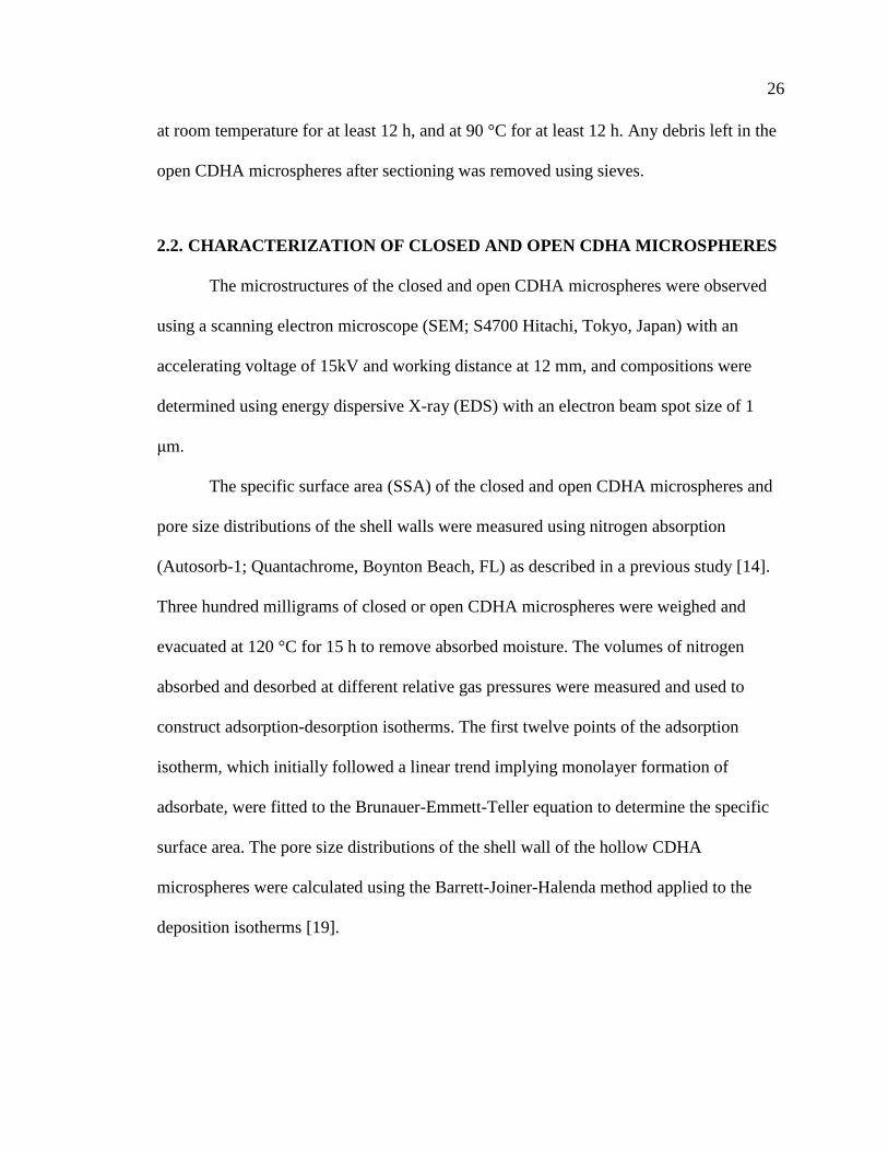
2.2. CHARACTERIZATION OF CLOSED AND OPEN CDHA
MICROSPHERES. ........................................................................................... 26
2.3. ANIMALS AND SURGICAL PROCEDURES .............................................. 27
2.4. HISTOLOGICAL PROCESSING .................................................................... 28
2.5. HISTOMORPHOMETRIC ANALYSIS .......................................................... 29
2.6. STATISTICAL ANALYSIS ............................................................................ 30
3. RESULTS ................................................................................................................. 30
3.1. GEOMETRY OF THE CLOSED AND OPEN CDHA MICROSPHERES .... 30
3.2. COMPOSITION OF THE CLOSED AND OPEN CDHA
MICROSPHERES ............................................................................................ 33
3.3. EVALUATION OF BONE REGENERATION IN RAT CALVARIAL
DEFECTS ......................................................................................................... 34
4. DISCUSSION .......................................................................................................... 42
5. CONCLUSIONS ...................................................................................................... 47
ACKNOWLEDGEMENTS ......................................................................................... 47
REFERENCES ............................................................................................................. 47
II. HOLLOW BIPHASIC CALCIUM PHOSPHATE MICROSPHERES FROM
GLASS DISSOLUTION AND REPRECIPITATION; PART I: PARTICLE
FORMATION AND CHARACTERIZATION ...................................................... 53
ABSTRACT ................................................................................................................. 53
1. INTRODUCTION .................................................................................................... 54
2. MATERIALS AND METHODS ............................................................................. 56
2.1. PREPARATION AND CHARACTERIZATION OF HOLLOW
BIPHASIC CALCIUM PHOSPHATE MICROSPHERES.............................. 56

viii
2.2. CHARACTERIZATION OF MICROSPHERES ............................................. 57
2.3. IN VITRO DEGRADATION BEHAVIOR OF CDHA AND BCP
MICROSPHERES ............................................................................................ 58
3. RESULTS ................................................................................................................. 59
3.1. MICROSTRUCTURES OF AS-PREPARED AND HEAT-TREATED
MICROSPHRES ............................................................................................... 59
3.2. PHASE DISTRIBUTIONS AND COMPOSITIONS OF THE AS-
PREPARED AND HEAT-TREATED MICROSPHERES .............................. 62
3.3. IN VITRO DEGRADATION ........................................................................... 65
3.3.1. Ion Release Kinetics in Potassium Acetate Solutions. ........................... 65
3.3.2. Apatite Formation in Simulated Body Fluid. ......................................... 67
4. DISCUSSION .......................................................................................................... 72
4.1. SYNTHESIS OF CDHA AND BCP MICROSPHERES ................................. 72
4.2. IN VITRO DEGRADATION OF CDHA AND BCP MICROSPHERES ....... 76
5. CONCLUSIONS ...................................................................................................... 78
ACKNOWLEDGEMENT............................................................................................ 78
REFERENCES ............................................................................................................. 79
III. HOLLOW BIPHASIC CALCIUM PHOSPHATE MICROSPHERES FROM
GLASS DISSOLUTION AND REPRECIPITATION; PART II: IN VIVO
STUDIES OF BONE REGENERATION AND BLOOD VESSEL
FORMATION ........................................................................................................ 84
ABSTRACT ................................................................................................................. 84
1. INTRODUCTION .................................................................................................... 85
2. MATERIALS AND METHODS ............................................................................. 86
2.1. PREPARATION AND CHARACTERIZATION OF HOLLOW
BIPHASIC CALCIUM PHOSPHATE MICROSPHERES.............................. 86
2.2. IN VIVO STUDIES OF CDHA AND BCP MICROSPHERES ...................... 87

ix
2.2.1. Calvarial Defects. ................................................................................... 87
2.2.2. Subcutaneous Defects. ............................................................................ 88
2.2.3. Histological Processing. ......................................................................... 88
2.2.4. Histomorphometric Analysis. ................................................................. 89
2.3. STATISTICAL ANALYSIS ............................................................................ 89
3. RESULTS ................................................................................................................. 90
3.1. HOLLOW CA-PHOSPHATE MICROSPHERES ........................................... 90
3.2. CALVARIAL IMPLANTATION .................................................................... 92
3.3. SUBCUTANEOUS IMPLANTATION ........................................................... 95
4. DISCUSSION .......................................................................................................... 99
4.1. IN VIVO DEGRADATION ............................................................................. 99
4.2. BONE REGENERATION IN VIVO ............................................................. 100
4.2.1. Bone Regeneration in Calvarial Defects. ............................................. 100
4.2.2. No Bone Regeneration in Subcutaneous Defects. ................................ 101
4.3. BLOOD VESSEL FORMATION IN SUBCUTANEOUS DEFECTS .......... 102
4.4. INFLAMMATION IN THE SUBCUTANEOUS DEFECTS ........................ 103
4.5. POTENTIAL APPLICATIONS ..................................................................... 104
5. CONCLUSIONS .................................................................................................... 104
ACKNOWLEDGMENT ............................................................................................ 104
REFERENCES ........................................................................................................... 105
IV. EVALUATION OF 13-93 GLASS SCAFFOLDS WITH CURVED
FILAMENTS TO ENHANCE BONE FORMATION IN RAT
CALVARIAL DEFECTS..................................................................................... 109
ABSTRACT ............................................................................................................... 109

x
1. INTRODUCTION .................................................................................................. 110
2. MATERIALS AND METHODS ........................................................................... 112
2.1. PREPARATION OF 13-93 GLASS SCAFFOLDS ....................................... 112
2.2. SURFACE MODIFICATION OF 13-93 GLASS SCAFFOLDS .................. 113
2.3. ANIMAL EXPERIMENTS ............................................................................ 114
2.4. HISTOLOGICAL PROCESSING .................................................................. 114
2.5. HISTOMORPHOMETRIC ANALYSIS ........................................................ 116
2.6. CHARACTERIZATION OF 13-93 GLASS SCAFFOLDS .......................... 117
2.7. STATISTICAL ANALYSIS .......................................................................... 118
3. RESULTS ............................................................................................................... 118
3.1. MICROSTRUCTURE OF 13-93 GLASS SCAFFOLDS .............................. 118
3.2. EVALUATION OF BONE REGENERATION IN RAT CALVARIAL
DEFECTS ....................................................................................................... 121
3.3. EVALUATION OF MINERALIZATION OF 13-93 GLASS
SCAFFOLDS .................................................................................................. 126
4. DISCUSSION ........................................................................................................ 130
5. CONCLUSIONS .................................................................................................... 135
ACKNOWLEDGMENT ............................................................................................ 135
REFERENCES ........................................................................................................... 136
SECTION
3. CONCLUSION ...................................................................................................... 142
3.1. SUMMARY .................................................................................................... 142
3.2. RECOMMENDATIONS FOR FUTURE WORK ......................................... 143
3.2.1. The Effect of Open CDHA Microspheres on Bone Regeneration. ...... 143

xi
3.2.2. Determine the Optimal Size of Open CDHA Microspheres
and Dosage of BMP-2 for Bone Regeneration. .................................... 144
3.2.3. Evaluation of BCP Microspheres in Bone Regeneration. .................... 144
3.2.4. 13-93 Glass Scaffolds with Curved Filaments for Bone
Regeneration. ....................................................................................... 144
APPENDICES
A. BONE REGENERATION FACILATED BY OPEN CDHA MICROSPHERES
LOADED WITH LOW DOSES OF BMP-2 ....................................................... 146
B. HOLLOW BIPHASIC CALCIUM PHOSPHATE MICROSPHERES FROM
GLASS DISSOLUTION AND REPRECIPITATION ........................................ 151
C. 13-93 GLASS SCAFFOLDS WITH CURVED FILAMENTS ............................ 159
BIBLIOGRAPHY ............................................................................................................162
VITA ................................................................................................................................172

xii
LIST OF ILLUSTRATIONS
SECTION Page
Figure 1.1. Schematic of the 3 primary stages for bone fracture healing [5]. .................... 2
Figure 1.2. The solubility of different stable calcium phosphate phases as a function
of pH.. ............................................................................................................... 4
Figure 1.3. Dependence of phosphate species in aqueous solutions on pH [23]. ............... 5
Figure 1.4. Schematic diagram presenting main steps in the conversion of calcium-
containing borate glass (Li-Ca-B glass as example) in phosphate solution. ..... 5
Figure 1.5. Hollow CDHA microspheres produced by glass conversion. ........................ 11
Figure 1.6. SEM images of silicate 13-93 bioactive glass scaffolds prepared by
robotic deposition (robocasting): (a) plane of deposition (xy plane);
(b) perpendicular to the deposition plane (z direction) [92]. .......................... 18
PAPER I
Figure 1. SEM images of 106-150 μm closed CDHA microspheres (A1, A2)
and open CDHA microspheres (B1, B2) and 212-250 μm closed
CDHA microspheres (C1, C2) and open CDHA microspheres (D1, D2). ....... 31
Figure 2. SEM images of an external surface (A) and internal surface (B) from
a 106-150 μm open CDHA microsphere, and an external surface (C)
and internal surface (D) of a 212-250 μm open CDHA microsphere. .............. 32
Figure 3. X-ray diffraction pattern of CDHA microspheres prepared by glass
conversion technique. ....................................................................................... 33
Figure 4. SEM images of cross section of 106-150 μm open CDHA
microspheres (A) and 212-250μm open CDHA microspheres (B)................... 34
Figure 5. H&E stained and von Kossa sections of implants composed of
closed (A1, B1) and open (A2, B2) CDHA microspheres
(ϕ106-150 μm) after 6 weeks in rat calvarial defects; (C, D) higher-
magnification images of boxed area in (A1, A2). ............................................. 37

xiii
Figure 6. H&E and von Kossa stained sections of implants composed of
closed (A1, B1) and open (A2, B2) CDHA microspheres
(ϕ212-250 μm) after 6 weeks in rat calvarial defects; (C, D) higher-
magnification images of boxed area in (A1, A2). ............................................. 38
Figure 7. H&E and von Kossa stained sections of implants composed of
closed (A1, B1) and open (A2, B2) CDHA microspheres
(ϕ106-150 μm) after 12 weeks in rat calvarial defects; (C, D) higher-
magnification images of boxed area in (A1, A2). ............................................. 39
Figure 8. H&E and von Kossa stained sections of implants composed of
closed (A1, B1) and open (A2, B2) CDHA microspheres
(ϕ212-250 μm) after 12 weeks in rat calvarial defects; (C, D) higher-
magnification images of boxed area in (A1, A2). ............................................. 40
Figure 9. Comparative new bone formation in implants with closed and
open CDHA microspheres with diameter of 106-150 μm or
212-250 μm after 6 weeks (6 W) and 12 weeks (12 W) in rat calvarial
defects (Mean ± SD; n = 5~10, * significant difference between
groups; p < 0.05). .............................................................................................. 41
Figure 10. Comparative von Kossa positive area for implants of closed and
open CDHA microspheres with diameter of 106-150 μm or
212-250 μm after 6 weeks (6 W) and 12 weeks (12 W) in rat calvarial
defects (Mean ± SD; n = 5~10, * significant difference between
groups; p < 0.05). .............................................................................................. 42
PAPER II
Figure 1. Schematic diagram illustrating the formation of hollow calcium
deficient hydroxyapatite microspheres and hollow biphasic calcium
phosphate microspheres. ................................................................................... 56
Figure 2. SEM images of hollow microspheres produced in 0.25M K2HPO4
solution at pH=7 and 12, showing representative cross-sections
(left), external surfaces (middle), and internal surfaces (right). ....................... 59
Figure 3. SEM images of hollow microspheres produced in 0.1M K2HPO4
solution at pH=7 and 12, showing representative cross-sections
(left), external surfaces (middle), and internal surfaces (right). ....................... 60
Figure 4. XRD patterns from the (A) as-prepared and (B) heat-treated microspheres
produced in 0.25M K2HPO4 solution at various pH values. ............................. 62

xiv
Figure 5. Ca/P ratios of as-prepared and heat-treated microspheres produced in
0.25 M and 0.1 M K2HPO4 solutions measured by ICP-OES and
estimated by XRD. ............................................................................................ 65
Figure 6. Time dependences of the release of (A) Ca and (B) P from different
microspheres to the KAc solution. (C) The Ca/P ion ratios released
from different microspheres to the KAc solutions. ........................................... 66
Figure 7. Weight changes in SBF solution at 37°C of the microspheres produced
in 0.1 M K2HPO4 solution. ............................................................................... 67
Figure 8. SEM images of the external surfaces of the microspheres produced in
0.1 M K2HPO4 solutions before (left) and after (right) two-weeks of
immersion in SBF solution at 37°C. (scale bar=500 nm) ................................. 69
Figure 9. FTIR (A, B) and Raman (C, D) spectra of the microspheres before and
after immersion in SBF solution for 14 days. ................................................... 70
PAPER III
Figure 1. Electron micrographs of the cross-sections (left), external surfaces
(center) and internal surfaces (right) of the CDHA and BCP hollow
microspheres used in this study; from [12]. ..................................................... 90
Figure 2. Optical images of H&E stained sections of rat calvarial defects
implanted with four groups of microspheres at 8 weeks.. ................................ 92
Figure 3. A comparison of A) new bone formation, and B) residual microspheres,
as a percentage of the total defect area, in rat calvarial defects
implanted with four group of microspheres at 8 weeks. ................................... 94
Figure 4. Optical images of H&E stained sections of rat subcutaneous defects
implanted with four groups of microspheres at 8 weeks.. ................................ 95
Figure 5. Optical images of H&E stained sections of rat subcutaneous defects
implanted with four groups of microspheres at 12 weeks. ............................... 96
Figure 6. Comparative areal fractions of blood vessels and foreign body giant
cells in implants with the four groups of microspheres after 8 weeks
and 12 weeks in rat subcutaneous defects (Mean ± SD; n = 6,
* significant difference between groups; p < 0.05)........................................... 98
PAPER IV
Figure 1. RoboCAD design of 13-93 glass scaffold with curved filaments. .................. 112

xv
Figure 2. Optical images of 13-93 glass scaffolds ground into a disc shapes:
A and B are a top-view and side view of the scaffold with straight
filaments, respectively; C and D are a top-view and side-view of the
scaffold with curved filaments, respectively. ................................................. 119
Figure 3. SEM images of as-fabricated 13-93 glass scaffolds with straight
filaments (A) in the xy-plane, (B) in the z-direction; and with curved
filaments (C) in the xy-plane, (D) in the z-direction. h indicates the
depth of a concave element. ............................................................................ 120
Figure 4. Angles at intersection of two filaments in the center part of the
as-fabricated scaffold with curved filaments. ................................................. 120
Figure 5. SEM images of surface-modified 13-93 glass scaffold: (A) cross-
section of converted scaffold filament and (B) surface of converted
glass filament. ................................................................................................. 121
Figure 6. H&E stained sections of implants composed of as-fabricated 13-93
glass scaffold with straight (A1) or curved (B1) filaments, and surface-
modified 13-93 glass scaffold with straight (C1) or curved (D1)
filaments, from rat calvarial defects after 6 weeks. ........................................ 122
Figure 7. H&E stained (A1-D1) and Toluidine blue stained (B2-D2) sections
from the center part of the implants: (A1, A2) as-fabricated scaffold
with straight filaments; (B1, B2) as-fabricated scaffold with curved
filaments; (C1, C2) surface-modified scaffold with straight filaments;
(D1, D2) surface-modified scaffold with curved filaments. ........................... 123
Figure 8. Comparative new bone formation in rat calvarial defects implanted
with 13-93 glass scaffolds at 6 weeks: as-fabricated scaffold with
straight filament; as-fabricated scaffolds with curved filaments;
surface-modified scaffold with straight filaments; surface-modified
scaffolds with curved filaments. ..................................................................... 125
Figure 9. Von Kossa stained sections of implants composed of as-fabricated
13-93 glass scaffold with straight (A) or curved (B) filaments or
surface-modified 13-93 glass scaffold with straight (C) or curved
(D) filaments, from rat calvarial defect after 6 weeks. ................................... 127
Figure 10. Comparative von Kossa positive areas for implants of 13-93 glass
scaffolds in rat calvarial defects after 6 weeks: as-fabricated scaffolds
with straight filaments; as-fabricated scaffolds with curved filaments;
surface-modified scaffolds with straight filaments; surface-modified
scaffolds with curved filaments. .................................................................... 128

xvi
Figure 11. Backscatter SEM images of implants composed of as-fabricated
13-93 glass scaffolds with straight (A1) or curved (B1) filaments,
or surface-modified 13-93 glass scaffold with straight (C1) or curved
(D1) filaments, from rat calvarial defects after 6 weeks; (A2-D2)
higher magnification images of boxed areas in (A1-D1). ............................. 129

xvii
LIST OF TABLES
SECTION Page
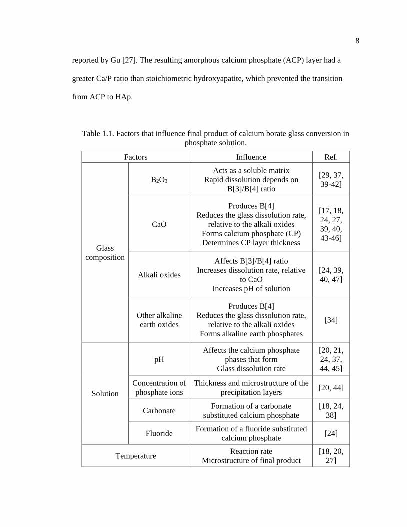
Table 1.1. Factors that influence final product of calcium borate glass conversion
in phosphate solution. ........................................................................................ 8
Table 1.2. Selected calcium phosphate phases of interest for biomedical
applications. [22, 48] ......................................................................................... 9
Table 1.3. The commercially BCP products and percentage ratios of composition
phases [75]. ...................................................................................................... 14
Table 1.4. Comparison of new bone formed in scaffolds composed of silicate
13-93 glass with different microstructures after implantation in rat
calvarial defects (4.0-4.6 mm in diameter 1.5 mm) [99]. ............................. 18
PAPER I
Table 1. Implants groups composed of closed or open hollow CDHA microspheres. ..... 27
Table 2. Surface area and average pore size of 106-150 μm and 212-250μm
CDHA microspheres. ......................................................................................... 32
Table 3. Ca/P (n = 10; mean ± SD) for the three layers that constitute the walls
of hollow CDHA microspheres. ......................................................................... 34
Table 4. Comparative new bone formation in all implants after 6 or 12 weeks
based on H&E staining. ...................................................................................... 41
PAPER II
Table 1. The diameter ratio of the hollow core (d) to the outer surface (D) of the
microspheres prepared under the conditions indicated, along with
their average particle sizes, surface areas and pore sizes. .................................. 61
Table 2. Fractions of HA and -TCP (wt%) and the Ca/P atomic ratios, from
XRD and ICP, for heat-treated microspheres produced in 0.25 M and
0.1 M K2HPO4 solutions at various pH values. .................................................. 64

xviii
PAPER III
Table 1. Microspheres used for in vivo tests (rat calvarial implantation and
subcutaneous implantation); compositions and properties are from [12]. ......... 91
Table 2. Summary of areal fractions of new bone formation and residual
microspheres in rat calvarial defects 8 weeks after implantation. ...................... 93
Table 3. Summary of the areal fractions of blood vessels and foreign body giant
cells in rat subcutaneous defects implanted with four groups of
microspheres at 8 weeks and 12 weeks. ............................................................. 97
PAPER IV
Table 1. 13-93 glass scaffolds used in this study. ........................................................... 114
Table 2. Percent new bone formed and total von Kossa positive area in rat
calverial defect implanted with the scaffolds at 6 weeks. ................................ 124
Table 3. Sequence of interfacial reactions involved in forming a bond between
bioactive glass and bone [35, 36]. .................................................................... 131

xix
NOMENCLATURE
Symbol Description
SEM Scanning electron microscopy
XRD X-ray diffraction
EDS Energy dispersive X-ray
ICP-OES Inductively-coupled optical emission spectroscopy
BET Brunauer-Emmett-Teller
BJH Barrett-Joiner-Halenda
SSA Specific surface area
ϕ Diameter
wt% Weight percent
SD Standard deviation
Ca/P Calcium to phosphorous ratio
FTIR Fourier transform infrared
H&E Hematoxylin and eosin
MCPM Monobasic calcium phosphate monohydrate
DCPA Dicalcium phosphate anhydrous, Monetite
DCPD Dibasic calcium phosphate dihydrate, Brushite
OCP Octacalcium phosphate
α-TCP α-tricalcium phosphate
ACP Amorphous calcium phosphate
CDHA Calcium deficient hydroxyapatite

xx
HA Hydroxyapatite
TTCP Tetracalcium phosphate
HCA Carbonate hydroxyapatite
BCP Biphasic calcium phosphate
BSA Bovine serum albumin
TGF-β Transforming growth factor-β
BMP Bone morphogenetic protein
SBF Simulated body fluid
KAc Potassium acetate

SECTION
1. INTRODUCTION
1.1. THE NEED FOR IMPROVED SYNTHETIC BONE GRAFTS
Effective regeneration of bone defects caused by trauma or chronic disease is a
significant clinical challenge. Over the past decades, researchers have investigated the
mechanism of bone regeneration in order to develop better healing strategies [1-3]. Bone
healing involves three primary stages: the early inflammatory stage, the repair stage, and
the late remodeling stage (Figure 1.1) [4, 5]. These three stages are distinct but
continuous. In the inflammatory stage, a hematoma forms and inflammatory cells
infiltrate the bone resulting in the formation of granulation tissue, vascular tissue and
immature tissue. During the repair stage, new blood vessels are developed to extend
tissue regeneration and growth; a soft callus is formed around the repair site, and then the
soft callus converts to a hard callus. Bone healing is completed during the remodeling
stage in which the bone is restored to its original shape, structure and mechanical
strength.
Bone defects are clinically reconstructed using treatments that rely on bone
regeneration and augmentation. While various treatments have been investigated with
encouraging results [6], complete and predictable bone reconstruction is often difficult to
achieve[7]. Autologous bone grafts taken from intra- or extra-oral sites are the gold
standard for treatment because they contain osteoinductive growth factors and osteogenic
cells, and they provide a structural scaffold. However, disadvantages include limited

2
tissue availability, increased surgery time, and additional pain and cosmetic imperfection
at the donor site [7-9]. Many of these issues can increase the health care cost for the
patient [10]. An alternative to autogenous bone is allogenic bone that can induce
moderate healing results due to its preserved osteoinductivity. However, allografts are
costly, have unpredictable performance due to donor variance and adverse immune
reactions, and they increase the risk of disease transference [11-13].Thus, there is a need
to develop improved synthetic bone substitutes with good in vivo performance.
Figure 1.1. Schematic of the 3 primary stages for bone fracture healing [5].
A number of bone graft substitute components are currently available. These
include inorganic materials (calcium phosphate and calcium sulfates in ceramics, pellets,
and injectable cements) and organic materials (demineralized bone matrix, bone
morphogenetic proteins). In the current bone substitute market, calcium phosphates,
bioactive glasses, and their combinations with polymeric materials, are among the most
commonly available synthetic bone substitutes [14].

3
1.2. DEVELOPMENT OF THE GLASS CONVERSION TECHNIQUE
Hench developed the first generation of bioactive glasses, including 45S5
Bioglass® (45% SiO2, 24.5% Na2O, 24.5% CaO, and 6% P2O5 –weight %) [15]. He
reported that a carbonate-substitute hydroxyapatite-like (HCA) layer formed on the
surface of 45S5 in contact with the body fluid. A borate analog glass, designated 45S5B1,
and having the same composition as 45S5 bioactive glass but with SiO2 replaced by
B2O3, was investigated by Richard [16]. She found that a calcium phosphate layer formed
on the glass surface after immersion in a K2HPO4 solution at 37°C; the calcium
phosphate layer formed faster on 45S5B1 borate glass than on 45S5 glass. Fears [17] and
Han [18] studied the reaction of glass spheres made from lithium calcium borate glass
and sodium calcium borate glass in 0.25 M phosphate solution at 37 °C, and they
reported the formation of hydroxyapatite.
1.2.1. Kinetics and Mechanism of Glass Conversion. The formation of a
calcium phosphate layer on the surface of a calcium-containing borate glass immersed in
a phosphate solution results from a series of dissolution-precipitation reactions. Ca2+ ions
are released from a dissolving glass to the aqueous solution and when the local solubility
limit is exceeded, these ions react with the phosphate anions to precipitate calcium
phosphate phases on the glass surface. The initial precipitation products are often x-ray
amorphous, with various Ca/P ratios depending on the experimental conditions, and so
are classified as amorphous calcium phosphates (ACP) [15, 19, 20]. Figure 1.2 shows the
solubility of different stable calcium phosphate phases as a function of pH [21, 22].
Hydroxyapatite (HA) is the most stable calcium phosphate phase in the pH range of
typical conversion processes (pH=9-12), although other calcium phosphates are stable in

4
acidic conditions, and will precipitate from solutions with greater salinity. Figure 1.3
shows the speciation of phosphate anions in aqueous solutions as a function of pH;
H2PO4- and HPO4
2- are the dominant anions in solutions with pH<10, and PO43- anions
become increasingly significant in more alkaline solutions.
Figure 1.2. The solubility of different stable calcium phosphate phases as a function of
pH. (A) 3D version of the classical solubility phase diagrams for the ternary system
Ca(OH)2–H3PO4–H2O. Bottom: solubility phase diagrams in two-dimensional graphs,
showing two logarithms of the concentrations of (B) calcium and (C) orthophosphate ions
as a function of the pH in solutions saturated with various salts [22].
As the glass continues to dissolve, the calcium phosphate layer grows inward
from the surface by the reaction of Ca2+ ions released from the glass with phosphate
A
B C
5
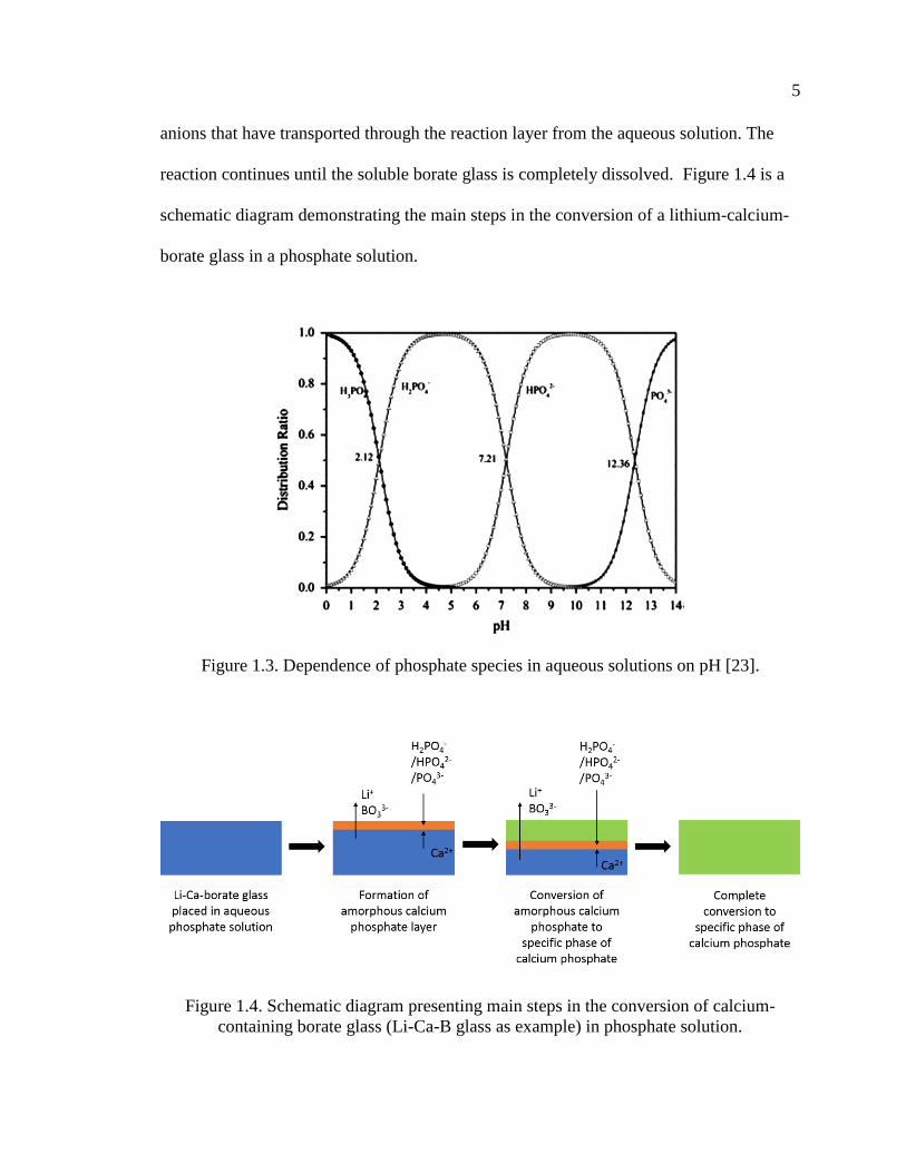
anions that have transported through the reaction layer from the aqueous solution. The
reaction continues until the soluble borate glass is completely dissolved. Figure 1.4 is a
schematic diagram demonstrating the main steps in the conversion of a lithium-calcium-
borate glass in a phosphate solution.
Figure 1.3. Dependence of phosphate species in aqueous solutions on pH [23].
Figure 1.4. Schematic diagram presenting main steps in the conversion of calcium-
containing borate glass (Li-Ca-B glass as example) in phosphate solution.

6
The final product of conversion is a calcium phosphate phase which depends on
the pH of the solution. In acidic solutions, dicalcium phosphate dihydrate (DCPD,
CaHPO4·2H2O) or dicalcium phosphate anhydride (DCPA, CaHPO4) can form [24],
whereas in basic solutions, non- stoichiometric, calcium-deficient hydroxyapatite
(CDHA, Ca10-x(HPO4)x(PO4)6-x(OH)2-x) can be produced [18, 20, 24]. Stoichiometric HA
has PO43- anions, some of which are replaced by HPO4
2- or other anions (e.g. CO32-) in
CDHA [22]. Similar effects of solution pH on the precipitation of Ca-phosphate phases
have been reported in other studies [25, 26].
The kinetics and mechanism of the formation of the CDHA layer on borate glass
have been investigated in several studies [27-31]. The kinetics of glass conversion is
often evaluated using weight loss data. The weight loss of glass is taken as the difference
between the initial (unreacted) mass of particles and the mass at time t [29, 32], with the
fraction of reacted glass given by . Several models, then, can be used to analyze (t),
assuming spherical particles in aqueous solutions [33]. The contracting volume model
(CVM) assumes a surface reaction-controlled mechanism where particles react with their
surroundings, and as the reaction progresses, the unreacted material uniformly decreases
in size. The kinetic equation for CVM is given as:
𝑘𝑐𝑣𝑚𝑡 = 1 − (1 − 𝛼)1/3 (1)
where is the fraction of sample reacted in time t and kCVM is the CVM reaction rate
constant. The three-dimensional diffusion model assumes that the transformation
reaction is limited by the diffusion of a species through a reaction product to the reaction
interface. The equation for the 3D diffusion is given as:

7
𝑘𝐷𝑡 = [1 − (1 − 𝛼)1/3]
2 (2)
where kD is the diffusion model reaction rate constant.
Huang, et al. [29, 34] studied the effect of partially or fully replacing the SiO2
content of 45S5 glass by B2O3 on the kinetics and mechanism of the conversion of glass
particles to CDHA. Yao [30] did similar work for borate-substituted 13-93 glass particles.
The conversion of particles of the borate analogue of 45S5 glass are well-described by a
3D diffusion model over the entire reaction time, whereas the conversion of the
borosilicate and silicate glasses was better described by a contracting volume model in
the initial stage and by a 3D diffusion model in the later stages [31].
Gu [27] studied the conversion of sodium calcium borate glasses to CDHA in
0.25 M K2HPO4. CVM had a good fit for glass conversion at 10, 22 and 37 °C. At 70 °C,
the early stage data followed a CVM, but the data was better fit by a diffusion model at
the later stages. The activation energy for the conversion reaction in the 10~70°C range
was 32~36 kJ/mol, which is similar to activation energies for hydration of borate
minerals [35, 36], indicating that glass dissolution controls the conversion kinetics.
George [37] investigated the conversion of 13-93B3 glass (12% K2O, 6% Na2O,
20% CaO, 5% MgO, 53% B2O3 and 4% P2O5 wt %) to calcium phosphate in water at 21
to 60 °C. The glass dissolution kinetics initially followed a reaction-controlled
contracting volume model. As the glass dissolved, a Mg-substituted amorphous calcium
phosphate layer precipitated on the glass surface. After the glass was ~25% reacted, the
dissolution kinetics transitioned to follow a diffusion-controlled model. Both the
reaction-controlled and diffusion-controlled kinetic reactions exhibited an Arrhenius
relationship, with activation energies of ~32 and 41 kJ/mol, respectively, similar to those
8
reported by Gu [27]. The resulting amorphous calcium phosphate (ACP) layer had a
greater Ca/P ratio than stoichiometric hydroxyapatite, which prevented the transition
from ACP to HAp.
Table 1.1. Factors that influence final product of calcium borate glass conversion in
phosphate solution.
Factors Influence Ref.
Glass
composition
B2O3
Acts as a soluble matrix
Rapid dissolution depends on
B[3]/B[4] ratio
[29, 37,
39-42]
CaO
Produces B[4]
Reduces the glass dissolution rate,
relative to the alkali oxides
Forms calcium phosphate (CP)
Determines CP layer thickness
[17, 18,
24, 27,
39, 40,
43-46]
Alkali oxides
Affects B[3]/B[4] ratio
Increases dissolution rate, relative
to CaO
Increases pH of solution
[24, 39,
40, 47]
Other alkaline
earth oxides
Produces B[4]
Reduces the glass dissolution rate,
relative to the alkali oxides
Forms alkaline earth phosphates
[34]
Solution
pH
Affects the calcium phosphate
phases that form
Glass dissolution rate
[20, 21,
24, 37,
44, 45]
Concentration of
phosphate ions
Thickness and microstructure of the
precipitation layers [20, 44]
Carbonate Formation of a carbonate
substituted calcium phosphate
[18, 24,
38]
Fluoride Formation of a fluoride substituted
calcium phosphate [24]
Temperature Reaction rate
Microstructure of final product
[18, 20,
27]

9
Table 1.2. Selected calcium phosphate phases of interest for biomedical applications. [22,
48]
Ca/P
Molar
Ratio
Name Formula pH stability
range at 25°C
Density
(g/cm3)
0.5
MCPM (monobasic
calcium phosphate
monohydrate)
Ca(H2PO4)2·H2O 0.0–2.0 2.22
1.0
DCPA (dicalcium
phosphate anhydrous,
Monetite)
CaHPO4 2.0–5.5 2.929
1.0
DCPD (dibasic
calcium phosphate
dihydrate, Brushite)
CaHPO4·2H2O 2.0-6.0 2.319
1.33 OCP (octacalcium
phosphate)
Ca8(HPO4)2(PO4)4
·5H2O 5.5-7.0 2.673
1.5 α-TCP (α-tricalcium
phosphate) α-Ca3(PO4)2
a 2.814
1.5 β-TCP (β-ticalcium
phosphate) β-Ca3(PO4)2
a 3.067
1.2-
2.2
ACP (amorphous
calcium phosphate)
CaxHy(PO4)z·nH2O
, n = 3-4.5, 15%-
20% H2O
~5-12b -
1.50-
1.67
CDHA (calcium
deficient
hydroxyapatite;
precipitated HAp,
pHA, pHAp)c
Ca10-
x(HPO4)x(PO4)6-
x(OH)2-x
(0 < x < 1)
6.5-9.5 -
1.67 HAp, or OHAp
(Hydroxyapatite) Ca10(PO4)6(OH)2 9.5-12.0 3.155
2.0
TTCP, or TetCP
(tetracalcium
phosphate,
Hilgenstockite)
Ca4(PO4)2O a 3.056
a These compounds cannot be precipitated from aqueous solutions. b Always metastable. The composition of the precipitate depends on the composition and
pH of the electrolyte solution. c Occasionally, it is called “precipitated HA (HAp)”.

10
1.2.2. Parameters that Influence the Glass Conversion Reaction. The
microstructural features of the calcium phosphate microspheres produced by the borate
glass conversion process depend on the process parameters (Table 1.1). Fears [17]
investigated the effect of the calcium content of lithium calcium borate glass spheres on
the reaction product formation in aqueous phosphate solutions. The thickness of the
calcium phosphate shell wall increased with increasing Ca-content in the initial glass
spheres. Glasses with ≤ 40 wt% CaO formed CDHA microspheres with a hollow core
and mesoporous shell. Glasses with > 40 wt% CaO formed solid but porous CDHA
microspheres. For the hollow microspheres, the ratio of the diameter of the hollow core
(d) to the outer shell diameter of the microsphere (D) was affected by the concentration
of the phosphate solution and the temperature in the system [20]. The d/D ratio decreased
as the concentration of the phosphate solution or temperature increased.
The composition of the converted product is affected by both the glass
composition and solution chemistry, including the pH value. Huang [34] investigated the
conversion of four-component borate glasses with the composition 10% Li2O, 10% CaO,
10% AeO and 60% B2O3 (wt%) in an aqueous phosphate solution, where Ae is the
alkaline earth element Mg or Ba. The reaction product after 30-50 hours was a calcium-
magnesium (or -barium) phosphate phase. For variations in solution chemistry, carbonate
or fluoride substituted CDHA could be produced by adding carbonate or fluoride ions to
the conversion solution [24, 38]. The formation of specific calcium phosphate phases
depends upon the pH of the solution. The stability of calcium phosphate phases, at
different pH values, has been studied previously (Table 1.2). Based on the stability of
these calcium phosphate phases, Vanderspiegel [24] related the transformation of

11
potassium calcium borate glasses to specific crystalline calcium phosphate phases. By
adjusting the pH of the conversion solution, these glasses produced three poorly-
crystallized calcium phosphate phases, including DCPD at pH≈4.4, DCPA at pH≈5.5,
and CDHA at pH≈9.2.
1.2.3. Hollow HA Microspheres. As mentioned before, the hollow HA
microsphere technology was developed at Missouri S&T to address the need for bone
graft substitution materials [17, 20, 49, 50]. Glass microspheres with the composition of
15CaO, 11Li2O,74B2O3 (wt%), designated CaLB3-15, were converted in 0.02 M
K2HPO4 solution at 37 °C and pH = 9 [49] to form hollow CDHA microspheres with
mesoporous shell walls, an example of which is shown in Figure 1.5.
Figure 1.5. Hollow CDHA microspheres produced by glass conversion. (A) Optical
image of starting glass (CaLB3-15) microspheres, and SEM images of (B) external
surface of hollow CDHA microsphere prepared by converting the glass microspheres for
48 h in 0.02M K2HPO4 solution at 37°C and pH = 9, (C) cross section of hollow CDHA
microsphere [49].

12
As a synthetic bone graft, the hollow CDHA microspheres lack the osteogenic
cells and osteoinductive growth factors present in autologous bone. However, hollow
CDHA microspheres can be combined with growth factors to enhance bone regeneration.
The hollow CDHA microspheres with high surface areas have been used as platforms for
controlled delivery of proteins [49-52]. Previous work at Missouri S&T showed that
hollow CDHA microspheres can absorb proteins like bovine serum albumin (BSA) [49],
transforming growth factor-β (TGF-β) [50], and bone morphogenetic protein-2 (BMP-2)
[52], and release these proteins in vitro or in vivo.
Implantation of the hollow HA microspheres in rat calvarial defects in vivo
stimulated limited new bone formation at 6 weeks and 12 weeks, whereas first loading
the hollow CDHA microspheres with TGF-β resulted in an improvement of new bone
formation in rat calvarial defects at 6 weeks, but not at 12 weeks [50].The new bone in
the implant with the microspheres loaded with TGF-β was only ~20% of the total defect
area after 6 weeks or 12 weeks. The hollow CDHA microspheres loaded with BMP-2 (1
g per defect) showed a significant increase in bone regeneration compared with the
microspheres without BMP-2 at 6 weeks. Hollow CDHA microspheres coated with
different thickness of poly(lactic-co-glycolic acid) (PLGA) delayed the release of BMP-2
[52].
Open CDHA microspheres are hollow CDHA microspheres (hereafter, called
closed HA microspheres) that have been sectioned, as shown in Figure 5C. From the
histological characterization of implants in rat calvarial defects, enhanced new bone
growth was noted in the micro-concavity of open CDHA microspheres [52]. Previous
work [53] showed that the open CDHA microspheres with exposed micro-concave

13
mesoporous hydroxyapatite in their cores promoted osteogenic differentiation of rat
mesenchymal stem cells and increased alkaline phosphatase activity in vitro compared to
closed CDHA microspheres. In the follow-up study [53], rat calvarial defects implanted
with the CDHA microspheres containing 50% open CDHA microspheres showed
considerable new bone formation in the many micro-concave regions of the open CDHA
microspheres. The enhanced osteogenic property of open CDHA microspheres is
presumably a result of their specific microgeometry.
Although the hollow CDHA microspheres showed promising results in bone
repair, the effectiveness of these open CDHA microspheres still needs to be improved to
optimize bone regeneration.
1.3. BIPHASIC CALCIUM PHOSPHATE
Hydroxyapatite (HA, Ca10(PO4)6(OH)2) is widely used as a synthetic bone graft
material for bone regeneration[22, 54, 55]. It is biocompatible and osteoconductive and
produces no systemic toxicity or immunological reactions. Osteoblasts and osteoclasts
adhere well to the surface of HA to form the cytoskeletal structure [56-59]. Moreover,
HA forms a chemical bond between the implant and surrounding bone [60]. However,
HA has found limited use as an implant material, principally because it lacks the
osteoinductivity and osteogenicity possessed by allografts or autografts [1, 14, 61, 62]. In
practice, mixing HA with osteogenic growth factors is often needed to achieve desirable
bone regeneration [1, 14, 61].

14
Table 1.3. Commercial BCP products and weight ratios of composition phases [75].
-TCP% HA% Brand name
<4 >96 Calciresorb (Ceraver, France)
20 80 Osteosynt (Einco, Brazil)
25 75 TCH (Kasios, France)
30 70 Ceratite (NGK Spark Plug, Japan)
OrthoCer HA TCP (Baumer, Brazil)
35 65
CuriOs (Progentix Orthobiology BV, Netherlands)
Ceraform (Teknimed, France)
Calcicoat (Zimmer, IN)
40 60
BCP (Depuy Bioland, France)
BCP BiCalPhos (Medtronic, MN)
BonaGraft (Biotech One, Taiwan)
BoneMedik-DM(Meta Biomed, Korea)
CellCeram (Scaffdex Oy, Finland)
GenPhos HA TCP (Baumer, Brazil)
Graftys BCP (Graftys, France)
Hatric (Arthrex, US)
Hydros (Biomatlante SA, France)
Kainos (Signus, Germany)
MasterGraft Granules (Medtronic Sofamor Danek,
US)
MBCP (Biomatlante SA, France)
OpteMx (Exactech, FL)
Ossceram nano (Bredent Medical, Germany)
Osteosynt (Einco, Brazil)
Ostilit (Stryker Orthopaedics, NJ)
SBS (ExpanScience, France)
TriOsite (Zimmer, IN)
4Bone (MIS, Israel)
45 55 CuriOs (Progentix Orthobiology BV, Netherlands)
Eurocer (FH, France)
50-70 30-50 Indost (Polystom, Russia)
80 20
BoneCeramic (Straumann, Switzerland)
BoneSave (Stryker Orthopaedics, NJ)
Kainos (Signus, Germany)
MBCP+ (Biomatlante SA, France)
OsSatura BCP (Integra Orthobiologics, CA)
Osteosynt (Einco, Brazil)
ReproBone (Ceramisys, UK)
Tribone 80 (Stryker, Europe)

15
Tricalcium phosphate (-TCP, Ca3(PO4)2), also known as bone ash, is a source for
calcium and phosphorus, which can be easily assimilated and absorbed by the body. -
TCP is also widely used in calcium phosphate bone cements [63-65], and other types of
bone-substitution bioceramics [66-68], including those for dental applications [69]. -
TCP is both osteoconductive and osteoinductive, and due to its low interfacial energy
with respect to apatite, it can provoke the precipitation of an apatite layer upon incubation
in aqueous ionic solutions [70]. β-TCP cannot be directly precipitated from aqueous
solutions [22]; instead, it forms when other phases, like CDHA [71] or mixtures of
materials like dicalcium phosphate anhydrous and CaO [72], are heated above about
800°C. β-TCP can also be prepared at relatively low temperatures (~150 °C) by
precipitation in water-free media, such as ethylene glycol [69].
In general, HA is poorly bioresorbable, whereas -TCP is more bioresorbable and
can be replaced by new bone at faster rates [22, 48]. These properties mean that the rate
of degradation and bioactivity of calcium phosphate implant materials can be tailored
using biphasic calcium phosphate (BCP) materials with a range of -TCP-to-HA ratios
[73, 74]. The in vivo dissolution/reprecipitation processes of BCP materials have been
studied extensively by TEM [73, 74]. Their dissolution rates are dependent on the -
TCP/HA ratio, and the microcrystals that form during reprecipitation have
crystallographic properties and Ca/P ratios similar to those of bone apatite [74].
Moreover, the new apatite crystals are defined as carbonate-apatite [73].
BCP ceramics with various ratios of -TCP and HA are known to be effective and
biocompatible scaffolds for tissue-engineering applications. The ratio between the more
soluble -TCP and the more stable HA has been varied to adjust the level of bioactivity,

16
bioresorbability, osteoconductivity, and osteoinductivity [75-78]. BCPs may be produced
by mixing HA and -TCP powders, or by sintering CDHAs at high temperature to
produce mixtures of the two different phases[78].
Although various BCP products with different -TCP/HA ratios have been
evaluated in large number of studies, there seems to be no agreement about the optimal
ratio of BCP phases for clinical applications [75]. Currently, there are over 30
commercially available BCP bone substitute products for various orthopedic and
maxillofacial applications. The commercial BCP products with relative -TCP/HA
weight ratios are summarized in Table 1.3 [75].
1.4. ADDITIVE MANUFACTURE OF BIOACTIVE GLASS SCAFFOLDS
Bioactive glasses are widely used as scaffold materials for bone repair, due to
their biocompatibility, osteoconductivity, their ability to form hydroxyapatite (HA) -like
layers in vivo, and their ability to form a strong bond with the host bone. By adjusting the
composition, a bioactive glass can release certain elements, such as boron [79], zinc [80,
81], copper [82, 83], and strontium [84], in a controlled manner that facilitates bone
regeneration. Bioactive silicate glasses, including 45S5 [85, 86] and 13-93 [87-89], have
been approved by the Food and Drug Administration (FDA) for in vivo use, and scaffolds
based on these bioactive glasses can be fabricated with different architectures to provide
desired mechanical and chemical environments for bone reconstruction. 13-93 (53SiO2,
6Na2O, 12K2O, 5MgO, 20CaO, 4P2O5, wt%) is a bioactive glass that is more stable
against crystallization than is 45S5 [90, 91], and so has been used in applications that

17
require heat treatments to consolidate glass particles or to create bonds between structural
elements by viscous flow [92-95].
Additive manufacturing techniques have led to innovative design and control of
scaffold architectures [96]. At Missouri S&T, porous bioactive glass scaffolds have been
fabricated using different manufacturing techniques, their in vitro mechanical properties
have been characterized, and their ability to support bone infiltration in vivo has been
evaluated. Mechanically strong porous scaffolds of 13-93 bioactive glass were created
using a freeze extrusion fabrication (FEF) technique [94, 97]. Subsequently, the
robocasting process was used to manufacture scaffolds from 13-93 bioactive glass [92,
98, 99].
Scaffolds with a grid-like microstructures (Figure 1.6), produced by robocasting
13-93 bioactive glass, promote the formation of new bone in rat calvarial defects.
Pretreatment of these glass scaffolds in a phosphate solution to convert a thin surface
layer of glass (~ 5 μm) to amorphous calcium phosphate or Ca-deficient hydroxyapatite
prior to implantation, significantly enhances the capacity of the scaffold in bone
regeneration [99]. Compared with other architectures of scaffolds made with the same
glass composition (Table 1.4), these results indicated that the grid-like architecture has a
better capacity to support bone regeneration than the oriented, trabecular and fibrous
structures. By loading the surface modified scaffold with BMP-2 (1 μg per defect), new
bone regeneration that infiltrated the scaffold significantly increased to 60% at six weeks
post-implantation [99].

18
Figure 1.6. SEM images of silicate 13-93 bioactive glass scaffolds prepared by robotic
deposition (robocasting): (a) plane of deposition (xy plane); (b) perpendicular to the
deposition plane (z direction) [92].
Table 1.4. Comparison of new bone formed in scaffolds composed of silicate 13-93 glass
with different microstructures after implantation in rat calvarial defects (4.0-4.6 mm in
diameter 1.5 mm) [99].
Microstructure
of scaffolds
Porosity
(%)
Pore size
(μm)
New bone (%) Implantation
time
(weeks)
Ref. Available
pore area
Total
area
Grid-like 47 300300150 32 ± 13 18 ± 8 6 [99]
Trabecular 80 100-500 25 ± 12 19 ± 9 12 [100]
Oriented 50 100-150 37 ± 8 18 ± 3 12 [100]
Fibrous 50 50-500 ~17a 8.5 ± 2 12 [101]
The amount of new bone is shown as a percent of the available pore space (area) in the
scaffolds and the total defect area. a Estimated from the total defect area.
Although the porous scaffolds of 13-93 bioactive glass with modified surfaces
were promising in healing bone defects in vivo, the ability to regenerate bone still needs

19
to be improved. Since the architecture of the glass scaffold plays an important role in
bone repair, optimization of these structures, made possible by additive manufacturing
techniques, may enhance the bone regeneration.
Rumpler et al [38] described curvature-driven effects that promoted in vivo tissue
formation in scaffolds, particularly on concave surfaces, and Paris et al. [19] developed a
scaffold curvature-mediated mechanism for the in vivo bio-mineralization of extra-
cellular matrix. An in vivo test showed that concavities stimulated the formation of blood
vessels which play an important role in bone regeneration [102]. Bone formation by
intramembranous ossification was preferred on a concave surface [103], and concavity
was shown to be conducive to the accumulation of growth factors, such as bone
morphogenetic proteins (BMPs) [104]. Based on these results, the addition of concave
structures into the design and fabrication of 13-93 glass scaffolds may have a positive
effect on bone regeneration.
In the end, it is clear that the microstructures and compositions of the materials
used for synthetic bone graft are significant factors for bone repair. Novel materials, like
those derived from the glass dissolution/precipitation process, and additive manufacturing
techniques like robocasting, provide researchers with new opportunities to optimize those
medical devices, and so to ultimately enhance a patient’s recovery from bone defects.

20
2. RESEARCH OBJECTIVE
The objective of this study is to investigate and improve two classes of
hydroxyapatite-based biomaterials for bone repair: 1) hollow calcium phosphate
microspheres with different microstructures and compositions, and 2) bioactive silicate
glass (13-93) scaffolds with different architectures to promote bone regeneration.
A considerable amount of new bone growth in the micro-concavity of open HA
microspheres was observed in previous work at Missouri S&T [52, 53]. As open HA
microspheres can be systematically obtained by sectioning closed HA microspheres, we
hypothesize that open HA microspheres with special characteristics can improve bone
regeneration compared to the closed HA microspheres. One goal of this study is to
investigate the dependence of microgeometry, size, and time on bone regeneration in an
osseous model, and then to evaluate the capacity of open HA microspheres loaded with
BMP-2 for bone regeneration in a rat calvarial defect model.
Additionally, previous studies [38, 50, 52] have shown that the hollow CDHA
microspheres alone have limited capacity for bone regeneration, likely because of their
chemical stability. In the present study, hollow BCP microspheres are described,
produced by heat-treating CDHA microspheres prepared using the glass conversion
technique. The degradation rates and performance in vitro and in vivo are evaluated.
Finally, considering the effects of scaffold architecture on bone regeneration, we
hypothesized that 13-93 glass scaffolds with curved filaments, produced by the
robocasting technique, may have improved capability to regenerate bone in vivo. Some

21
scaffolds were pre-reacted in a phosphate solution to form a thin HA-like layer, prior to
implantation and the capability of 13-93 glass scaffolds with curved filaments to facilitate
bone formation is evaluated using a rat calvarial defect model.

22
PAPER
I. EVALUATION OF OPEN HOLLOW CDHA MICROSPHERES ON BONE
REGENERATION IN RAT CALVARIAL DEFECTS
Youqu Shen1, Mohamed Rahaman1, Yongxian Liu1, Yue-Wern Huang2
1Department of Materials Science and Engineering, Missouri University of Science and
Technology Rolla, MO, 65409
2Department of Biological Sciences, Missouri University of Science and Technology
Rolla, MO, 65409
ABSTRACT
Hollow Ca-deficient hydroxyapatite (CDHA) microspheres facilitate bone
regeneration in rats with non-healing calvarial defects. Open CDHA microspheres were
obtained by sectioning closed hollow CDHA microspheres. The open CDHA
microsphere had dense outer (convex) surfaces and rough and porous inner (concave)
surfaces. For both size ranges (ϕ106-150 μm vs. ϕ212-250 μm), the open CDHA
microsphere were more effective in facilitating bone regeneration than the closed CDHA
microspheres in rat calvarial defects. After twelve weeks, bone regeneration in the open
CDHA microspheres (49 ± 7% for ϕ106-150 μm; 40 ± 8% for ϕ212-250 μm) was greater
than the closed CDHA microspherse (26 ± 8% for ϕ106-150 μm; 30 ± 9% for ϕ212-250
μm). Furthermore, the smaller open CDHA microspheres showed a significant increase in
bone regeneration over the larger open CDHA microspheres at both 6 weeks and 12
weeks. The difference in bone regeneration between these microspheres may be due to

23
their differences in microstructures, namely curvature, concavity, porosity, surface
roughness, and total surface area available for cell attachment.
1. INTRODUCTION
Effective regeneration of bone defects caused by trauma or chronic diseases is a
significant clinical challenge. Over the past few decades, researchers have investigated
the mechanism of bone regeneration to better inform the designs of healing strategies [1-
3]. Bone healing involves three primary stages: the early inflammatory stage; the repair
stage and the late remodeling stage [4]. These three stages are distinct, but continuous. In
the inflammatory stage, a hematoma forms and inflammatory cells infiltrate the bone,
resulting in the formation of granulation tissue, vascular tissue and immature tissue.
During the repair stage, new blood vessels are developed to facilitate tissue regeneration
and a soft callus is formed around the repair site. Bone healing is completed during the
remodeling stage in which the bone is restored to its original shape, structure and
mechanical strength.
Clinically, bone deficiency is overcome using treatments that rely on bone
regeneration and augmentation. While various treatments have been investigated with
encouraging results [5], complete and predictable bone reconstruction is often difficult
[6]. Autologous bone grafts are the gold standard for treatment because they contain
osteoinductive growth factors, osteogenic cells and a structural scaffold. However,
disadvantages of this treatment include limited tissue availability, increased surgery time,
additional pain and cosmetic imperfection at the donor site [6-8]. Many of these issues

24
can increase the health care cost for the patient [9]. An alternative to autogenous bone is
allogenic bone, which can induce moderate healing results due to its preserved
osteoinductivity. However, allografts are costly, can have unpredictable effects on growth
due to donor variance, cause adverse immune reactions, and increase the risk of disease
transference [10-12]. Synthetic bone grafts have advantages such as consistent quality,
safety, and good tissue tolerance, but they usually function as inert or merely
osteoconductive implants. Encouraging results have been reported.
Hydroxyapatite (HA), the main component and essential ingredient of human
bone, can be prepared by various methods. Studies have demonstrated that HA supports
bone regeneration and bonding to surrounding tissue because of its biocompatibility,
bioactivity, and osteoconductivity [13]. Closed hollow microspheres composed of Ca-
deficient hydroxyapatite (CDHA) can be produced using the glass conversion technique
[14]. Previous studies showed that closed CDHA microspheres promoted the
regeneration of bone in non-healing rat calvarial defects [15, 16], and that the mechanical
properties and biological response depended on the microsphere size (ϕ106-150 𝜇m and
ϕ150-250 𝜇m) [17]. In these in vivo tests, it was occasionally observed that better bone
regeneration was associated with broken microspheres with exposed micro-concavity [16,
18], and this observation is the motivation for the present study, to see more
systematically if open CDHA microsphere with particular geometric characteristics can
yield better bone regeneration compared with the closed CDHA microspheres. Closed
and open CDHA microspheres with two size ranges (ϕ106-150 μm and ϕ212-250 μm) of
were created and bone regeneration was evaluated with a rat calvarial defect model.

25
2. MATERIALS AND METHODS
2.1. PREPARATION OF CLOSED AND OPEN CDHA MICROSPHERES
The closed hollow CDHA microspheres were prepared by conversion of solid
glass microspheres in an aqueous phosphate solution, as described in a previous study
[14]. Briefly, calcium-lithium-borate glass with the composition of 15CaO, 11Li2O and
74B2O3 (wt%), designated as CaLB3-15, was prepared by melting CaCO3, Li2CO3, and
H3BO3 (Alfa Aesar, Haverhill, MA, USA) in a platinum crucible at 1200 °C for 45 min
and then quenching the melt between stainless steel plates. Glass particles were obtained
by grinding the glass using a a mortar and pestle, crushing the powder in a shatter box,
and sieving through 100 and 140 mesh (US standard) sieves for the ϕ106-150 μm size
range, or 60 and 70 mesh sieves for the ϕ212-250 μm size range. Glass microspheres
were obtained by dropping the particles down through a vertical furnace at 1200 °C. The
closed hollow hydroxyapatite microspheres were obtained by reacting the glass
microspheres in a 0.02 M K2HPO4 solution at 37 °C and pH = 9 for 7 days. In the
conversion process, 1 g glass was immersed in a 200 ml phosphate solution and the
system was stirred gently and continuously. The converted microspheres were washed
with distilled water and anhydrous ethanol, and then dried at room temperature for at
least 12 h, and at 90 °C for at least 12 h.
The open CDHA microspheres were obtained by sectioning the closed hollow
CDHA microspheres using a microtome. Briefly, the closed CDHA microspheres were
fixed on a wax block using a water-soluble tape and were sectioned by microtome. The
open CDHA microspheres were washed with distilled water and ethanol, and then dried
26
at room temperature for at least 12 h, and at 90 °C for at least 12 h. Any debris left in the
open CDHA microspheres after sectioning was removed using sieves.
2.2. CHARACTERIZATION OF CLOSED AND OPEN CDHA MICROSPHERES
The microstructures of the closed and open CDHA microspheres were observed
using a scanning electron microscope (SEM; S4700 Hitachi, Tokyo, Japan) with an
accelerating voltage of 15kV and working distance at 12 mm, and compositions were
determined using energy dispersive X-ray (EDS) with an electron beam spot size of 1
μm.
The specific surface area (SSA) of the closed and open CDHA microspheres and
pore size distributions of the shell walls were measured using nitrogen absorption
(Autosorb-1; Quantachrome, Boynton Beach, FL) as described in a previous study [14].
Three hundred milligrams of closed or open CDHA microspheres were weighed and
evacuated at 120 °C for 15 h to remove absorbed moisture. The volumes of nitrogen
absorbed and desorbed at different relative gas pressures were measured and used to
construct adsorption-desorption isotherms. The first twelve points of the adsorption
isotherm, which initially followed a linear trend implying monolayer formation of
adsorbate, were fitted to the Brunauer-Emmett-Teller equation to determine the specific
surface area. The pore size distributions of the shell wall of the hollow CDHA
microspheres were calculated using the Barrett-Joiner-Halenda method applied to the
deposition isotherms [19].
27
2.3. ANIMALS AND SURGICAL PROCEDURES
All animal use and care procedures were approved by the Missouri S&T
Institutional Animal Care and Use Committee in compliance with the NIH Guide for
Care and Use of Laboratory Animals (1985). The rat calvarial defects were implanted
with four groups of implants composed of closed or open hollow CDHA microspheres
for 6 weeks and 12 weeks (Table 1). The implantation time was based upon considerable
bone regeneration in rat calvarial defects implanted with hollow CDHA microspheres
observed in previous studies [15, 16]. Closed or open CDHA microspheres in the two
size ranges were randomly implanted into defect areas, but mixing implants of closed and
open microspheres in the same animal was avoided due to the possible migration of low-
weight open CDHA microspheres.
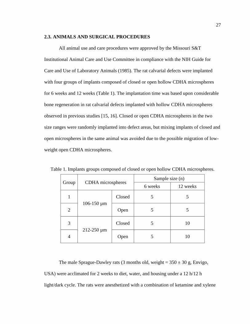
Table 1. Implants groups composed of closed or open hollow CDHA microspheres.
Group CDHA microspheres Sample size (n)
6 weeks 12 weeks
1
106-150 µm
Closed 5 5
2 Open 5 5
3
212-250 µm
Closed 5 10
4 Open 5 10
The male Sprague-Dawley rats (3 months old, weight = 350 ± 30 g, Envigo,
USA) were acclimated for 2 weeks to diet, water, and housing under a 12 h/12 h
light/dark cycle. The rats were anesthetized with a combination of ketamine and xylene

28
(0.15 μl per 100 g) and maintained under anesthesia with isoflurane in oxygen. The
surgery area on each animal was shaved, scrubbed with 70% ethanol and iodine, and then
draped. With sterile instruments and using an aseptic technique, a 1 cm cranial skin
incision was made in an anterior to posterior direction along the midline. The
subcutaneous tissue, musculature and periosteum were dissected and reflected to expose
the calvaria. Bilateral full thickness defects (4.6 mm in diameter) were created in the
central area of each parietal bone using a saline-cooled trephine drill. The sites were
constantly irrigated with sterile PBS to prevent overheating of the bone margins and to
remove the bone debris. Each defect was randomly implanted with the CDHA
microspheres from the four diffeent groups. After implantation, one drop of Ringer’s
solution was added to each defect. The periosteum and skin were repositioned and closed
with wound clips. Each animal received an intramuscular injection of ~200 μl
buprenorphine and ~200 μl penicillin post-surgery. All animals were monitored daily for
the condition of the surgical wound, food intake, activity and clinical signs of infection.
After 6 or 12 weeks, the animals were sacrificed by CO2 inhalation, and the calvarial
defect sites with surrounding bone and soft tissue were harvested for subsequent
evaluations.
2.4. HISTOLOGICAL PROCESSING
Harvested calvarial samples were fixed in a 10% formaldehyde solution for five
days. The samples were cut into half after being washed with deionized water. Half of the
sample was for paraffin embedding, and the other half was for poly (methyl
methacrylate) (PMMA) embedding. The paraffin-embedded samples were decalcified in

29
14 wt% ethylenediaminetetraacetic acid (EDTA, Sigma-Aldrich, USA) for 2 weeks,
dehydrated in ethanol, and then embedded in paraffin using standard histological
techniques. These samples were sectioned using a microtome. The thickness of the tissue
section with paraffin was 5 μm. These slices were then stained with hematoxylin and
eosin (H&E) [20]. Without decalcification, the samples for PMMA embedding were
dehydrated in ethanol and embedded in PMMA. These samples were sectioned, affixed to
acrylic slices, and ground to a thickness down to 50 μm using a micro-grinding system
(EXAKT 400CS, Norderstedt, Germany). The von Kossa staining was used to observe
mineralization [21].
2.5. HISTOMORPHOMETRIC ANALYSIS
Histomorphometric analysis was carried out using optical images of stained
sections and Image J software (National Institutes of Health, USA). The percentage of
new bone formed in a calvarial defect was evaluated from the H&E stained sections. The
newly formed bone was identified by outlining the edge of the defect, with the presence
of old and new bone being identified by lamellar and woven bone, respectively. The total
defect area was measured from one edge of the old calvarial bone, including the entire
implant and tissue within it, to the other edge of the old bone. The newly formed bone
within this area was then outlined and measured; the amount of the new bone was
expressed as a percentage of the total defect area. The amount of von Kossa positive area
is shown as a percent of the total defect area.

30
2.6. STATISTICAL ANALYSIS
Measurements of the percentage of new bone (relative to the entire defect area)
are expressed as a mean ± SD. Analysis for differences between groups was performed
using one-way analysis of variance (ANOVA) followed by the Tukey’s post hoc test; the
differences were considered significant at p < 0.05.
3. RESULTS
3.1. GEOMETRY OF THE CLOSED AND OPEN CDHA MICROSPHERES
The closed CDHA microspheres were prepared by converting glass microspheres
in a phosphate solution. The diameters of the starting glass microspheres were either
ϕ106-150 μm or ϕ212-250 μm. After conversion, changes in the diameter of the
microspheres were negligible. The SEM images revealed a spherical shape for the closed
CDHA microspheres with two size ranges: ϕ106-150 μm (hereafter, small size; Figure
1A1 and A2) and ϕ212-250 μm (thereafter, large size; Figure 1C1 and C2). Open CDHA
microspheres were sectioned from closed CDHA microspheres using a microtone. The
SEM images confirmed successful formation of hemispherical open CDHA microspheres
with both sizes (Figure 1B1, B2, D1 and D2). The hollow microspheres have a hollow
core with a diameter of about 60% of the overall microsphere diameter. The shell wall
consists of two distinct layers: a denser external layer, about ~ 5 μm thick, and a more
porous internal layer. Figure 2 shows representative high-resolution images of the inner
and outer surfaces of open microspheres. The outer surfaces consist of uniform

31
distributions of nanoparticles, and the inner surfaces appear to have rougher
agglomerations of similar nanoparticles.
Figure 1. SEM images of 106-150 μm closed CDHA microspheres (A1, A2) and open
CDHA microspheres (B1, B2) and 212-250 μm closed CDHA microspheres (C1, C2) and
open CDHA microspheres (D1, D2).
A1 A2
B1 B2
C1 C2
D1 D2

32
Figure 2. SEM images of an external surface (A) and internal surface (B) from a 106-150
μm open CDHA microsphere, and an external surface (C) and internal surface (D) of a
212-250 μm open CDHA microsphere.
Table 2. Surface area and average pore size of closed 106-150 μm and 212-250μm
CDHA microspheres.
HA microspheres Surface area (m2/g) Average pore size (nm)
106-150 µm 101 13
212-250 µm 168 10
The BET surface area and average pore size of the two sets of closed CDHA
microspheres are summarized in Table 2. The surface areas of small and large closed
CDHA microspheres were 101 m2/g and 168 m2/g, respectively. The average pore sizes
of small and large closed CDHA microspheres were 13 nm and 10 nm, respectively. The
D C
A B

33
surface area was greater in the large CDHA microspheres, whereas the average pore size
was greater in the small CDHA microspheres.
3.2. COMPOSITION OF THE CLOSED AND OPEN CDHA MICROSPHERES
Figure 3. X-ray diffraction pattern of CDHA microspheres prepared by glass conversion
technique. The pattern of a reference hydroxyapatite (HA, 01-076-0694) is also shown.
The board peak in XRD pattern of CDHA (Figure 3) indicated that the materials
is poorly crystallized, or nanocrystal, or a combination of both. High-resolution cross-
sectional SEM images of representative hollow CDHA microspheres are shown in Figure
4. The shell walls of the microspheres were divided into three regions: external layer,
middle layer and inner layer. The Ca/P atomic ratio at the midpoint of each region was
analyzed by EDS (Table 3). There was no significant difference between the Ca/P ratios
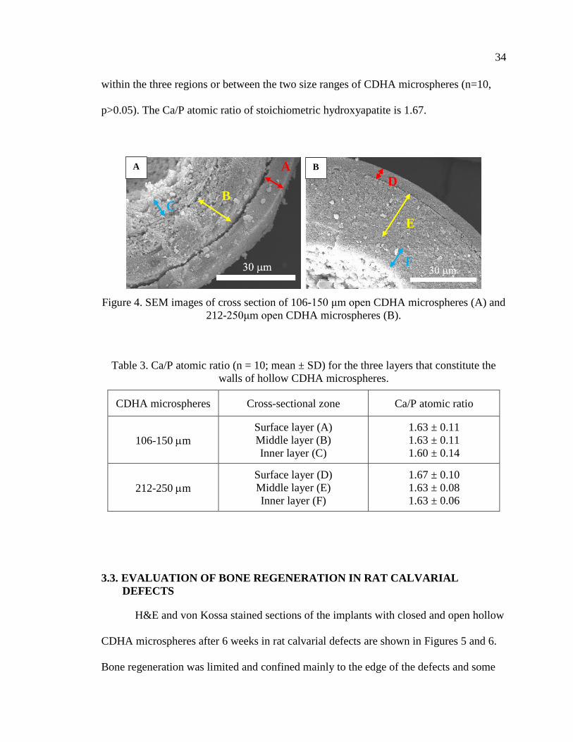
34
within the three regions or between the two size ranges of CDHA microspheres (n=10,
p>0.05). The Ca/P atomic ratio of stoichiometric hydroxyapatite is 1.67.
Figure 4. SEM images of cross section of 106-150 μm open CDHA microspheres (A) and
212-250μm open CDHA microspheres (B).
Table 3. Ca/P atomic ratio (n = 10; mean ± SD) for the three layers that constitute the
walls of hollow CDHA microspheres.
CDHA microspheres Cross-sectional zone Ca/P atomic ratio
106-150 m
Surface layer (A)
Middle layer (B)
Inner layer (C)
1.63 ± 0.11
1.63 ± 0.11
1.60 ± 0.14
212-250 m
Surface layer (D)
Middle layer (E)
Inner layer (F)
1.67 ± 0.10
1.63 ± 0.08
1.63 ± 0.06
3.3. EVALUATION OF BONE REGENERATION IN RAT CALVARIAL
DEFECTS
H&E and von Kossa stained sections of the implants with closed and open hollow
CDHA microspheres after 6 weeks in rat calvarial defects are shown in Figures 5 and 6.
Bone regeneration was limited and confined mainly to the edge of the defects and some
B C
A A
F
E
D
B

35
bone bridging along the bottom of implants. Fibrous tissues (light blue in H&E stained
sections) filled the space between the microspheres. New bone formation in the implants
with the smaller closed and open CDHA microspheres was 12 ± 3% and 17 ± 6%,
respectively (Figure 5 and Table 4). The von Kossa positive areas in in the implants with
the smaller closed and open CDHA microspheres were 41 ± 3% and 49 ± 5%,
respectively (Table 5). The percentages of new bone in the implants with the larger
closed and open CDHA microspheres were 6 ± 2 % and 12 ± 3%, respectively (Figure 6).
The von Kossa positive areas in the implants with the larger size of closed and open
CDHA microspheres were 30 ± 3% and 35 ± 3%, respectively. Open CDHA
microspheres showed significant improvement in bone regeneration compared with
closed CDHA microspheres for both size ranges at 6 weeks in rat calvarial defects (n = 5,
p < 0.05 for both sizes, Figures 9 and 10). Smaller closed CDHA microspheres showed a
significant increase in bone regeneration than the larger closed CDHA microspheres (n =
5, p < 0.05). Based on the H&E results, there was a borderline difference in new bone
formation between the two size ranges of open CDHA microspheres (n = 5, p = 0.050).
However, based on von Kossa results, the smaller open CDHA microspheres showed a
significant enhancement in bone growth compared to the larger open CDHA
microspheres (n = 5, p < 0.001).
Higher magnification images of the closed and open HA microspheres are shown
in Figure 5C and D (from the boxed areas of Figure 5A1 and A2) and Figure 6C and D
(from the boxed areas in Figure 6A1 and A2). For the closed HA microspheres with both
size ranges, little bone formation was noted, fibrous tissue filled the pore spaces between
the closed CDHA microspheres and infiltrated into the hollow cores of some broken

36
closed HA microspheres. In comparison, more bone regeneration was observed in the
micro-concavity of open CDHA microspheres (indicated by blue arrows) in both sizes
(ϕ106-150 μm and ϕ212-250 μm).
The outcomes from the implants with the closed and open CDHA microspheres of
the two size ranges after 12 weeks in rat calvarial defects are shown in Figures 7 and 8.
New bone tissue formed from the edge of the defects and on the bottom of the implants.
For the open CDHA microspheres, more new bone growth in the micro-concavities can
be found; the remaining open CDHA microspheres can be observed in the new bone
bridging the ends of defects. For the smaller closed and open CDHA microspheres
(Figure 7), the percentages of new bone formation were 26 ± 8% and 49 ± 7%,
respectively; the von Kossa positive areas were 55 ± 5% and 76 ± 4%, respectively. For
the larger closed and open CDHA microspheres (Figure 8), the percentages of new bone
were 30 ± 9% and 40 ± 8%, respectively; the von Kossa positive areas were 56 ± 5% and
65 ± 5%, respectively. The open CDHA microspheres showed significant improvement
in bone regeneration when compared to the closed CDHA microspheres, for both size
ranges, after 12 weeks in rat calvarial defects (n = 5, p < 0.001 for small size; n = 5, p <
0.05 for large size). There was no significant difference in new bone formation between
the two size ranges for the closed CDHA microspheres (n = 5~10, p > 0.05). However,
smaller open CDHA microspheres showed a more significant increase in bone
regeneration than larger open CDHA microspheres (n = 5, p < 0.05). Bone regeneration
was time-dependent for both size ranges; new bone formation increased significantly
from 6 weeks to 12 weeks in rat calvarial defects (n = 5, p < 0.001 for closed CDHA
microspheres; n = 5~10, p < 0.001 for open CDHA microspheres).

37
Figure 5. H&E stained and von Kossa sections of implants composed of closed (A1, B1)
and open (A2, B2) CDHA microspheres (ϕ106-150 μm) after 6 weeks in rat calvarial
defects; (C, D) higher-magnification images of boxed area in (A1, A2). HB: host bone;
NB: new bone. Blue arrow: new bone growth in micro-concavity.

38
Figure 6. H&E and von Kossa stained sections of implants composed of closed (A1, B1)
and open (A2, B2) CDHA microspheres (ϕ212-250 μm) after 6 weeks in rat calvarial
defects; (C, D) higher-magnification images of boxed area in (A1, A2). HB: host bone;
NB: new bone. Blue arrow: new bone growth in micro-concavity.

39
Figure 7. H&E and von Kossa stained sections of implants composed of closed (A1, B1)
and open (A2, B2) CDHA microspheres (ϕ106-150 μm) after 12 weeks in rat calvarial
defects; (C, D) higher-magnification images of boxed area in (A1, A2). HB: host bone;
NB: new bone. Blue arrow: new bone growth in micro-concavity.

40
Figure 8. H&E and von Kossa stained sections of implants composed of closed (A1, B1)
and open (A2, B2) CDHA microspheres (ϕ212-250 μm) after 12 weeks in rat calvarial
defects; (C, D) higher-magnification images of boxed area in (A1, A2). HB: host bone;
NB: new bone. Blue arrow: new bone growth in micro-concavity.

41
Table 4. Comparative new bone formation in all implants after 6 or 12 weeks based on
H&E staining. The amount of new bone is expressed as a percent of the total defect area
(mean ± SD).
CDHA microspheres
New bone (%)
6 weeks 12 weeks
ϕ106-150 μm
Closed 12 ± 3 26 ± 8
Open 17 ± 6 49 ± 7
ϕ212-250 μm
Closed 6 ± 2 30 ± 9
Open 12 ± 3 40 ± 8
Figure 9. Comparative new bone formation in implants with closed and open CDHA
microspheres with diameter of 106-150 μm or 212-250 μm after 6 weeks (6 W) and 12
weeks (12 W) in rat calvarial defects (Mean ± SD; n = 5~10, * significant difference
between groups; p < 0.05).

42
Figure 10. Comparative von Kossa positive area for implants of closed and open CDHA
microspheres with diameter of 106-150 μm or 212-250 μm after 6 weeks (6 W) and 12
weeks (12 W) in rat calvarial defects (Mean ± SD; n = 5~10, * significant difference
between groups; p < 0.05).
A comparison of closed and open HA microspheres in both sizes at 12 weeks is
shown in higher magnified images in Figure 6C and D (from the boxed areas of Figure
6A1 and A2) and Figure 7C and D (from the boxed areas of Figure 7A1 and A2). Bone
regeneration in the cores of some broken closed CDHA microspheres was identified. A
higher degree of new bone formation in the micro-concavity of open CDHA
microspheres was observed.
4. DISCUSSION
The ability of CDHA microspheres to regenerate bone can presumably be affected
by the differences between closed and open CDHA microspheres in microstructure. In

43
this study, the microstructure of closed and open CDHA microspheres in two size ranges
(ϕ106-150 μm vs. ϕ212-250 μm) were analyzed. To test CDHA microspheres in
facilitating bone regeneration, rat calvarial defects were created and CDHA microspheres
were implanted. Bone regeneration was evaluated in weeks 6 & 12.
For both size ranges, the thickness of the denser (outer) layer was ~ 5 μm, while
the ratio of the hollow core diameter to the microsphere diameter is ~0.6. The factors
leading to these two distinct layers are still unclear. In the glass conversion process [17,
22-24], ions are released from the soluble glass (i.e., Ca2+, Li+, B3+) to the aqueous
phosphate solution. When the concentration of Ca2+ ions exceeds the local solubility
limit, those ions react with phosphate anions solution to form calcium phosphate. As the
glass dissolves, the calcium phosphate layer continues to thicken until the glass is
completely converted to calcium phosphate. The kinetics and mechanism of the
formation of the calcium phosphate layer in borate glass have been investigated in several
studies [23, 25-27]. The conversion rate is initially described by a reaction-controlled
model (linear kinetics); however, at the later stage, a three-dimensional diffusion model
(parabolic kinetics) better explains the conversion rate. Presumably, the denser outer
layer and porous inner layers result from these two kinetic models. Additional
experiments can be set-up to further investigate the dynamic changes of SSA and pore
size.
The in vivo experiments showed that the open CDHA microspheres were effective
in promoting bone formation. For both size ranges of the open CDHA microspheres, new
bone formation was observed in both 6 weeks and 12 weeks post-implantation. The
amount of new bone growth increased from 6 weeks to 12 weeks. In the study of 12-

44
week implantation with small microspheres, new bone formation with the implants of
open microsphere was about twice that of the closed microspheres; for large
microspheres, new bone formation in the implants of open microspheres was about 30%
higher than that of the closed microspheres. Thus, the open microspheres were more
effective in facilitating bone regeneration than the closed microspheres. Compared to the
closed microsphere, the open microsphere had a micro-concave region with a more
porous and rougher surface (see Figures 1 and 2). These characters (i.e., micro-concavity,
porosity, roughness) could contribute to the difference in bone regeneration between the
closed and open microspheres.
The effectiveness of micro-concave surfaces in promoting bone regeneration has
been investigated by others [28-33]. For example, substantial mineralization was
observed within the concavities, but not at the planar surfaces, of calcium phosphate
ceramic discs in simulated body fluid, and smaller concavities (0.4 mm diameter) induced
more mineralization than larger concavities (0.8 mm or 1.8 mm diameter) [32]. An in
vivo study demonstrated that concavities stimulated the formation of blood vessels, a
critical process for bone formation [33]. Stem cells showed better outcomes on a concave
surface than a flat surface in terms of cell maturation, osteodifferentiation, and specific
protein production [29]. Bone formation by intramembranous ossification was favored on
a concave surface as well [31]. Concavity is also conducive to the accumulation of
growth factors such as BMPs [28]. Differences in microstructure may also be a
contributing factor to the outcome of bone regeneration. The internal concave surface
was more porous and rougher compared to external convex surface (Figure 2).

45
The differences in porosity and roughness could influence dissolution/degradation
of biomaterials, adsorption of growth factors, and mineral deposition from body fluids
[34-41]. For instance, the degradation of a porous surface could lead to faster Ca2+ release
which is a key factor in facilitating angiogenesis [42]. Further, a more porous and rougher
surface could be a more suitable substrate for adsorption of biologically active molecules,
such as BMPs and growth factors. Together, these lead to enhanced cell attachment,
proliferation and differentiation.
Dissolution/degradation rates of calcium phosphates have been shown to be
affected by the ratio of Ca/P of the material [43-45]. For example, the dissolution rate of
a calcium phosphate in water increased as the Ca/P ratio decreased [43]. Higher
dissolution/degradation of HA could release more Ca2+ and phosphate ions, which could
facilitate bone regeneration. It is possible that the Ca/P ratio of the CDHA can be
manipulated to achieve varying degree of dissolution. In this study, there was no
significant difference in Ca/P ratio within the three regions or between the two size
ranges of CDHA microspheres.
The current study demonstrated that the small open microspheres induced a more
significant increase in bone regeneration than the large open microspheres at both 6
weeks and 12 weeks. One reason for this difference may be attributed to the greater total
surface area made available by the open microspheres for cell attachment. For equivalent
masses of particles, there will be nearly twice as much available surface area for the open
particles compared to the closed particles. Another reason for the difference in bone
regeneration could be due to the inner surface curvature of the open microspheres. The
small microspheres have higher curvature than the large microspheres. It remains to be

46
investigated how the curvature of the microspheres affect cellular physiology leading to
the differential outcome of bone regeneration.
An apparent observation is that new bone formation with implants of the small
open microspheres was able to completely bridge the defects at the bottoms of all the
implants (Figure 7). In comparison, few of the defects with closed microspheres were
bridged. During the regeneration process, new bone formation started from the edge of
the host bone and from the bottom of the defect (dura matter), where osteogenic cells and
blood supply were abundant. The open microspheres might absorb the osteogenic factors
by diffusion or fluid transport and trigger bone growth in the micro-concavity. The open
microspheres at the bottom of the implants had the best chance of contact with the
osteogenic factors not only from dura matter but also from the edges induced by the open
microsphere in periphery.
In the present study, the smaller (ϕ106-150 μm) open CDHA microspheres
promoted more new bone formation than the larger open microspheres (ϕ212-250 μm) in
rat calvarial defects. However, the optimum size of the open microspheres still needs to
be determined. Furthermore, the open CDHA microspheres with high surface area could
be applied as a device for protein/drug delivery and should be evaluated in future studies.
Overall, this study demonstrated that open CDHA microspheres have better capacity to
enhance bone formation than the closed CDHA microspheres, and their efficiency to
simulate bone regeneration depends on particle size.
47
5. CONCLUSIONS
The open CDHA microspheres significantly enhance bone regeneration compared
to the closed CDHA microspheres at both 6 weeks and 12 weeks in rat calvarial defects.
Compared with the larger size of open CDHA microspheres (smaller curvature), the
smaller size of open CDHA microspheres (larger curvature) resulted in a more significant
increase in bone regeneration. The differences in the microstructures of the CDHA
microspheres (i.e., curvature, concavity, porosity, surface roughness, total surface area
available for cell attachment) may deserve future attention.
ACKNOWLEDGEMENTS
The work was financially supported by the National Institutes of Health [Grant
#1R15DE023987-01]. We appreciate the technical support of members of the Missouri
S&T Materials Research Center and the Department of Biological Sciences, and the
assistance of Richard Watters of the Animal Research Facility.
REFERENCES
[1] V. Campana, G. Milano, E. Pagano, M. Barba, C. Cicione, G. Salonna, W.
Lattanzi, and G. Logroscino, Bone substitutes in orthopaedic surgery: from basic
science to clinical practice. Journal of Materials Science: Materials in Medicine,
2014. 25(10): p. 2445-2461.
[2] F. Deschaseaux, L. Sensébé, and D. Heymann, Mechanisms of bone repair and
regeneration. Trends in Molecular Medicine, 2009. 15(9): p. 417-429.

48
[3] F. Loi, L.A. Córdova, J. Pajarinen, T.-h. Lin, Z. Yao, and S.B. Goodman,
Inflammation, fracture and bone repair. Bone, 2015. 86: p. 119-130.
[4] I.H. Kalfas, Principles of bone healing. Neurosurg Focus, 2001. 10(4): p. E1.
[5] A. Scarano, M. Degidi, G. Iezzi, G. Pecora, M. Piattelli, G. Orsini, S. Caputi, V.
Perrotti, C. Mangano, and A. Piattelli, Maxillary sinus augmentation with
different biomaterials: a comparative histologic and histomorphometric study in
man. Implant dentistry, 2006. 15(2): p. 197-207.
[6] L. Trombelli, Which reconstructive procedures are effective for treating the
periodontal intraosseous defect? Periodontology 2000, 2005. 37(1): p. 88-105.
[7] R.T. Kao, G. Conte, D. Nishimine, and S. Dault, Tissue engineering for
periodontal regeneration. Journal of the California Dental Association, 2005.
33(3): p. 205-215.
[8] N. Pandit, R. Malik, and D. Philips, Tissue engineering: A new vista in
periodontal regeneration. Journal of Indian Society of Periodontology, 2011.
15(4): p. 328-337.
[9] C. Dahlin, A. Johansson, a. Sahlgrenska, S.f.A.B. Institute of Clinical Sciences,
D.o.B. Orthopaedics, u. Göteborgs, U. Gothenburg, s.f.a.b.o.o.A.f.b. Institutionen
för kliniska vetenskaper, and A. Sahlgrenska, Iliac crest autogenous bone graft
versus alloplastic graft and guided bone regeneration in the reconstruction of
atrophic maxillae: a 5‐year retrospective study on cost‐effectiveness and clinical
outcome. Clinical Implant Dentistry and Related Research, 2011. 13(4): p. 305-
310.
[10] P.V. Giannoudis, H. Dinopoulos, and E. Tsiridis, Bone substitutes: an update.
Injury, 2005. 36(3): p. S20-S27.
[11] J.A. McAuliffe, Bone graft substitutes. Journal of Hand Therapy, 2003. 16(2): p.
180-187.
[12] O. Reikerås, H. Shegarfi, C. Naper, F.P. Reinholt, and B. Rolstad, Impact of MHC
mismatch and freezing on bone graft incorporation: An experimental study in
rats. Journal of Orthopaedic Research, 2008. 26(7): p. 925-931.
[13] A. Von Recum and J.E. Jacobi, Handbook of biomaterials evaluation: scientific,
technical, and clinical testing of implant materials. 1999, Taylor & Francis:
Philadelphia, PA.

49
[14] H. Fu, M.N. Rahaman, and D.E. Day, Effect of process variables on the
microstructure of hollow hydroxyapatite microspheres prepared by a glass
conversion method. Journal of the American Ceramic Society, 2010. 93(10): p.
3116-3123.
[15] H. Fu, M.N. Rahaman, R.F. Brown, and D.E. Day, Evaluation of bone
regeneration in implants composed of hollow HA microspheres loaded with
transforming growth factor β1 in a rat calvarial defect model. Acta Biomaterialia,
2013. 9(3): p. 5718-5727.
[16] W. Xiao, H. Fu, M.N. Rahaman, Y. Liu, and B.S. Bal, Hollow hydroxyapatite
microspheres: A novel bioactive and osteoconductive carrier for controlled
release of bone morphogenetic protein-2 in bone regeneration. Acta
Biomaterialia, 2013. 9(9): p. 8374-8383.
[17] H. Fu, Hollow hydroxyapatite microspheres as devices for controlled delivery of
proteins and as scaffolds for tissue engineering. Doctoral Dissertations, Missouri
University of Science and Technology, 2012.
[18] M.N. Rahaman, W. Xiao, Y. Liu, and B. Sonny Bal, Osteoconductive and
Osteoinductive Implants Composed of Hollow Hydroxyapatite Microspheres, in
Advances in Bioceramics and Porous Ceramics VII. 2014, John Wiley & Sons,
Inc: Hoboken, NJ, USA. p. 65-79.
[19] E.P. Barrett, E.P. Barrett, L.G. Joyner, L.G. Joyner, P.P. Halenda, and P.P.
Halenda, The determination of pore volume and area distributions in porous
substances. I. Computations from nitrogen isotherms. Journal of the American
Chemical Society, 1951. 73(1): p. 373-380.
[20] J.Q. Feng, J. Zhang, S.L. Dallas, Y. Lu, S. Chen, X. Tan, M. Owen, S.E. Harris,
and M. Macdougall, Dentin matrix protein 1, a target molecule for cbfa1 in bone,
ss a unique bone marker gene. Journal of Bone and Mineral Research, 2002.
17(10): p. 1822-1831.
[21] L.F. Bonewald, S.E. Harris, J. Rosser, M.R. Dallas, S.L. Dallas, N.P. Camacho,
B. Boyan, and A. Boskey, Von Kossa staining alone is not sufficient to confirm
that mineralization in vitro represents bone formation. Calcified Tissue
International, 2003. 72(5): p. 537-547.
[22] K.P. Fears, Formation of hollow hydroxyapatite microspheres. Masters Theses,
Missouri University of Science and Technology, 2001.

50
[23] G.H. Nancollas and J. Zhang, Formation and dissolution mechanisms of calcium
phosphates in aqueous systems, in Hydroxyapatite and related materials, P.W.
Brown and B. Constantz, Editors. 1994, CPC Press, Inc.: United State of
America. p. 73-81.
[24] Q. Wang, W. Huang, D. Wang, B.W. Darvell, D.E. Day, and M.N. Rahaman,
Preparation of hollow hydroxyapatite microspheres. Journal of Materials Science:
Materials in Medicine, 2006. 17(7): p. 641-646.
[25] Y. Gu, W. Xiao, L. Lu, W. Huang, M.N. Rahaman, and D. Wang, Kinetics and
mechanisms of converting bioactive borate glasses to hydroxyapatite in aqueous
phosphate solution. Journal of Materials Science, 2011. 46(1): p. 47-54.
[26] W. Huang, M.N. Rahaman, D.E. Day, and Y. Li, Mechanisms for converting
bioactive silicate, borate, and borosilicate glasses to hydroxyapatite in dilute
phosphate solution. Physics and Chemistry of Glasses-European Journal of Glass
Science and Technology Part B, 2006. 47(6): p. 647-658.
[27] A.-H. Yao, J. Lin, X. Duan, and W.-H. Huang, Formation mechanism of
multilayered structure on surface of bioactive borosilicate glass. Chinese Journal
of Inorganic Chemistry, 2008. 24(7): p. 1132-1136.
[28] U. Ripamonti, Functionalized Surface Geometries Induce:“Bone: Formation by
Autoinduction”. Frontiers in physiology, 2018. 8: p. 1084.
[29] A. Graziano, R. d'Aquino, M.G. Cusella-De Angelis, G. Laino, A. Piattelli, M.
Pacifici, A. de Rosa, and G. Papaccio, Concave Pit-Containing Scaffold Surfaces
Improve Stem Cell-Derived Osteoblast Performance and Lead to Significant Bone
Tissue Formation. PLoS ONE, 2007. 2(6): p. e496.
[30] C. Gray, A. Boyde, and S. Jones, Topographically induced bone formation in
vitro: implications for bone implants and bone grafts. Bone, 1996. 18(2): p. 115-
123.
[31] M.J. Coathup, K.A. Hing, S. Samizadeh, O. Chan, Y.S. Fang, C. Campion, T.
Buckland, and G.W. Blunn, Effect of increased strut porosity of calcium
phosphate bone graft substitute biomaterials on osteoinduction. Journal of
Biomedical Materials Research Part A, 2012. 100A(6): p. 1550-1555.
[32] M. Bianchi, E.R. Urquia Edreira, J.G.C. Wolke, Z.T. Birgani, P. Habibovic, J.A.
Jansen, A. Tampieri, M. Marcacci, S.C.G. Leeuwenburgh, and J.J.J.P. van den
Beucken, Substrate geometry directs the in vitro mineralization of calcium
phosphate ceramics. Acta Biomaterialia, 2014. 10(2): p. 661-669.

51
[33] A. Scarano, V. Perrotti, L. Artese, M. Degidi, D. Degidi, A. Piattelli, and G. Iezzi,
Blood vessels are concentrated within the implant surface concavities: a
histologic study in rabbit tibia. Odontology, 2014. 102(2): p. 259-266.
[34] H. Yuan, Z. Yang, Y. Li, X. Zhang, J.D. De Bruijn, and K. De Groot,
Osteoinduction by calcium phosphate biomaterials. Journal of Materials Science:
Materials in Medicine, 1998. 9(12): p. 723-726.
[35] C.B. Danoux, D. Barbieri, H. Yuan, J.D. de Bruijn, C.A. van Blitterswijk, and P.
Habibovic, In vitro and in vivo bioactivity assessment of a polylactic
acid/hydroxyapatite composite for bone regeneration. Biomatter, 2014. 4(1): p.
e27664.
[36] S. Fujibayashi, M. Neo, H.-M. Kim, T. Kokubo, and T. Nakamura,
Osteoinduction of porous bioactive titanium metal. Biomaterials, 2004. 25(3): p.
443-450.
[37] E. García-Gareta, J. Hua, J.C. Knowles, and G.W. Blunn, Comparison of
mesenchymal stem cell proliferation and differentiation between biomimetic and
electrochemical coatings on different topographic surfaces. Journal of Materials
Science: Materials in Medicine, 2013. 24(1): p. 199-210.
[38] D. Barbieri, A.J.S. Renard, J.D. de Bruijn, and H. Yuan, Heterotopic bone
formation by nano-apatite containing poly (D,L-lactide) composites. European
cells & materials, 2010. 19: p. 252-261.
[39] K.L. Kilpadi, P.-L. Chang, and S.L. Bellis, Hydroxylapatite binds more serum
proteins, purified integrins, and osteoblast precursor cells than titanium or steel.
Journal of Biomedical Materials Research, 2001. 57(2): p. 258-267.
[40] F.B. Bagambisa and U. Joos, Preliminary studies on the phenomenological
behaviour of osteoblasts cultured on hydroxyapatite ceramics. Biomaterials,
1990. 11(1): p. 50-56.
[41] K.A. Hing, Bioceramic bone graft substitutes: Influence of porosity and
chemistry. International Journal of Applied Ceramic Technology, 2005. 2(3): p.
184-199.
[42] A. Aguirre, A. González, M. Navarro, Ó. Castaño, J.A. Planell, and E. Engel,
Control of microenvironmental cues with a smart biomaterial composite promotes
endothelial progenitor cell angiogenesis. European Cells and Materials, 2012. 24:
p. 90-106.

52
[43] E. Mavropoulos, A.M. Rossi, N.C.C. da Rocha, G.A. Soares, J.C. Moreira, and
G.T. Moure, Dissolution of calcium-deficient hydroxyapatite synthesized at
different conditions. Materials Characterization, 2003. 50(2): p. 203-207.
[44] F. Driessens, Formation and stability of calcium phosphates in relation to the
phase composition of the mineral in calcified tissues, in Bioceramics Calcium
Phosphate. 2018, CRC Press. p. 1-32.
[45] A. Tofighi, K. Schaffer, and R. Palazzolo. Calcium phosphate cement (CPC): a
critical development path. in Key Engineering Materials. 2008. Trans Tech Publ.

53
II. HOLLOW BIPHASIC CALCIUM PHOSPHATE MICROSPHERES FROM
GLASS DISSOLUTION AND REPRECIPITATION; PART I: PARTICLE
FORMATION AND CHARACTERIZATION
Youqu Shen1, Richard K. Brow1
1Department of Materials Science and Engineering, Missouri University of Science and
Technology Rolla, MO, 65409
ABSTRACT
Hollow biphasic calcium phosphate (BCP) microspheres have been prepared with
different fractions of hydroxyapatite (HA) and β-tricalcium phosphate (β-TCP) and their
in vitro reactivities determined. The microspheres were prepared by reacting soluble
borate glasses in phosphate solutions (0.1 M or 0.25M K2HPO4) with different values of
pH (7-12) to produce hollow calcium-deficient hydroxyapatite (CDHA) microspheres
with Ca/P ratios that increased with solution pH. Heating the CDHA microspheres to
800°C produced hollow, nanoporous BCP microspheres with ratios of nanocrystalline
HA and β-TCP that correspond to the Ca/P ratio of the CDHA precursors. CDHA
particles converted in pH=7 solutions (Ca/P≈1.55) and pH=12 solutions (Ca/P≈1.59)
produced BCP microspheres with -TCP/HA=70/30 and -TCP/HA=44/56, respectively.
The CDHA microspheres reacted more quickly in acetic acid than the BCP microspheres,
and for the latter, those with a greater -TCP/HA ratio were more reactive. CDHA and
BCP microspheres converted to nanocrystalline carbonated hydroxyapatite when
immersed in 37°C simulated body fluid (SBF).

54
1. INTRODUCTION
Carbonated-hydroxyapatite, with the general formula (Ca, Na, Mg)10(PO4, HPO4,
CO3)6(OH, Cl, F)2 [1-4], is the mineral phase in hard tissue. Because of their
biocompatibility and bioactivity, synthetic calcium phosphate ceramics, including
hydroxyapatite (HA, Ca10(PO4)6(OH)2) and -tricalcium phosphate (-TCP, Ca3(PO4)2)
are widely used as biomedical implant materials [5].
Synthetic HA is osteoconductive and produces no systemic toxicity or
immunological reactions. However, HA has found limited use as an allograft or autograft
implant material, principally because HA lacks the osteoinductivity and osteogenicity
possessed by allografts or autografts [6-9]. In practice, mixing HA with osteogenic
growth factors is often needed to achieve desirable bone regeneration [6-8]. Compared to
HA, -TCP is both osteoconductive and osteoinductive, and due to its low interfacial
energy with respect to apatite, it can provoke the precipitation of an apatite layer upon
incubation in aqueous ionic solutions [10]. β-TCP cannot be precipitated from aqueous
solutions; instead, it forms when other phases[11], like calcium deficient hydroxyapatite
[12] or mixtures of materials like dicalcium phosphate anhydrous and CaO [13], are
heated above about 800°C. β-TCP can also be prepared at relatively low temperatures
(~150 °C) by precipitation in water-free mediums, such as ethylene glycol [14].
Calcium phosphate microspheres can be produced by reacting Ca-containing
soluble borate glass microspheres in a phosphate solution. By varying the glass
composition [15], solution pH value [16], solution chemistry [17-19], and temperature
[17, 20], the compositions and structures of the calcium phosphate microspheres can be

55
modified. For example, by adjusting the solution pH, the glass conversion process can
produce semi-crystalline forms of dicalcium phosphate dehydrate (DCPD, pH=4.4),
dicalcium phosphate anhydride (DCPA, pH=5.5), and calcium-deficient hydroxyapatite
(pH=9.2) [16].
The objective of the present study is to create hollow biphasic calcium phosphate
microspheres with controlled degradation rates and to characterize their performance in
vitro and in vivo. In Part I of this study, the glass conversion process used in previous
studies to produce HA microspheres from CDHA microspheres with a range of Ca/P
ratios is described, as is their conversion by heat treatments to hollow BCP microspheres
with a range of β-TCP/HA ratios. Compositions and phase distributions were determined
by analytical scanning electron microscopy, x-ray diffraction, and Raman spectroscopy.
The relative reactivity of CDHA and BCP particles, in acetic acid and in simulated body
fluid (SBF), is described. In Part II [21], the results of in vivo implantations of CDHA
and BCP microspheres in rat calvarial defects (8 weeks) and subcutaneous defects (8 and
12 weeks) are described. BCP microspheres with greater fractions of β-TCP were found
to promote a greater fractions of new bone formation in the calvarial defects and new
blood vessel formation in the subcutaneous defects than CDHA particles and BCP
particles with lower fractions of β-TCP.

56
2. MATERIALS AND METHODS
2.1. PREPARATION AND CHARACTERIZATION OF HOLLOW BIPHASIC
CALCIUM PHOSPHATE MICROSPHERES
A schematic diagram for making hollow CDHA and BCP microspheres is shown
in Figure 1.
Figure 1. Schematic diagram illustrating the formation of hollow calcium deficient
hydroxyapatite microspheres and hollow biphasic calcium phosphate microspheres.
Hollow CDHA microspheres were obtained by the glass conversion technique
described in previous studies [17]. Briefly, a lithium-calcium- borate glass with the
nominal composition 11Li2O, 15CaO, and 74B2O3 (wt%) was prepared by melting
appropriate amounts of Li2CO3, CaCO3, and H3BO3 (Alfa Aesar, Haverhill, MA, USA) in
a platinum crucible at 1200 °C for 45 min, then quenching the melt between stainless
steel plates. Glass particles with sizes between 150 and 250 μm were obtained by
grinding the glass in a shatter box and sieving through 60 and 100 mesh sieves. Glass
microspheres were obtained by dropping the crushed particles through a vertical furnace
Phosphate
solution
Adjust pH
Heat
treatment
800 °C
Li-Ca-B glass Ca-deficient
hydroxyapatite
Biphasic
calcium
phosphate
(-TCP/HA)

57
at 1200 °C. The glass microspheres were reacted in K2HPO4 solutions (0.1 M or 0.25M)
with pH values ranging between 7 and 12 at 37°C for 2-4 days, at a ratio of 1 g glass in
200 ml phosphate solution, while stirring continuously. The initial pH of the phosphate
solution was set using appropriate amounts of HCl or NaOH. The converted
microspheres were washed with distilled water and anhydrous ethanol, and then dried at
room temperature for at least 12 h, and then at 90 °C for at least 12 h. After conversion,
some CDHA microspheres were converted to BCP microspheres by heating them in a
platinum dish in air at 800°C for 5 hours.
2.2. CHARACTERIZATION OF MICROSPHERES
The microstructures of as-prepared and heat-treated microspheres were
characterized by scanning electron microscopy (SEM) (S4700, Hitachi, Tokyo, Japan), at
an accelerating voltage of 15 kV and working distance of 12.5 mm. Phase compositions
were analyzed using X-ray diffraction (XRD) (PANalytical X’Pert Pro multi-purpose
diffractometer). The XRD data were acquired in the 2θ range of 5-90° at a scanning
speed of 2.8°/min using Cu K radiation (λ=0.15406 nm). The diffraction data were
compared with JCPDS cards of HA (01-076-0694) and β-TCP (01-070-2065),
respectively. The weight fractions of HA and β-TCP in the heat-treated microspheres
were estimated by matching the intensities of respective peaks with the intensity of each
pure phase. The Ca/P ratios of the microspheres were determined by dissolving them in
10% HNO3 solution and then measuring the respective concentrations of calcium and
phosphorus using inductively-coupled optical emission spectroscopy (ICP-OES) (Avio
200; Perkin Elmer, Waltham, MA).

58
Nitrogen absorption techniques (Surface Area & Pore Size Analyzer; NOVA
2000e; Quantachrome, Boyton Beach, FL) were used to determine specific surface areas
(SSA) of the microspheres (Brunauer-Emmett-Teller (BET) analyses) and the pore size
distributions in their respective shell walls (Barrett-Joiner-Halenda (BJH) method). Three
replicates for each group were measured and average values are reported.
2.3. IN VITRO DEGRADATION BEHAVIOR OF CDHA AND BCP
MICROSPHERES
The aqueous degradation rates of microspheres were determined using two
methods. For the accelerated degradation tests, 15 mg of the microspheres were
immersed in 50 ml of a potassium acetate acidic buffer (0.1M, pH=5.0) at 37 °C. Calcium
and phosphorus concentrations in the solution were determined as a function of
immersion time (0-3 days) using ICP-OES. In the second test, microspheres were
immersed in SBF [22] with starting pH of 7.4 at 37 °C. Changes in microsphere mass and
solution pH values were measured at various times. Both tests were run in triplicate, and
averages and standard deviations are reported.
After 14-days of immersion in SBF solution, the microspheres were removed,
washed gently using deionized water, dried, and analyzed using SEM, as described
above. The Raman spectra of the microspheres before and after SBF immersion were
analyzed by µ-Raman spectrometer (ARAMIS; Horiba-Jobin Yvon, Inc.; Edison, NJ)
using a He-Ne laser (632.8 nm). Finally, these microspheres were analyzed by Fourier
transform infrared (FTIR) spectroscopy (Nicolet iS50; Thermo Scientific; Madison, WI)
using the single-bounce attenuated total reflectance accessory.

59
3. RESULTS
3.1. MICROSTRUCTURES OF AS-PREPARED AND HEAT-TREATED
MICROSPHRES
Figure 2. SEM images of hollow microspheres produced in 0.25M K2HPO4 solution at
pH=7 and 12, showing representative cross-sections (left), external surfaces (middle), and
internal surfaces (right).

60
Figure 3. SEM images of hollow microspheres produced in 0.1M K2HPO4 solution at
pH=7 and 12, showing representative cross-sections (left), external surfaces (middle), and
internal surfaces (right).
Micrographs of representative as-prepared and heat-treated microspheres,
produced by conversion in 0.25 M and 0.1 M K2HPO4 solutions, are shown in Figures 2
and 3, respectively. SEM images of the cross-sections indicate that the microspheres have
porous shells and a hollow core. In general, the diameters of the hollow cores in
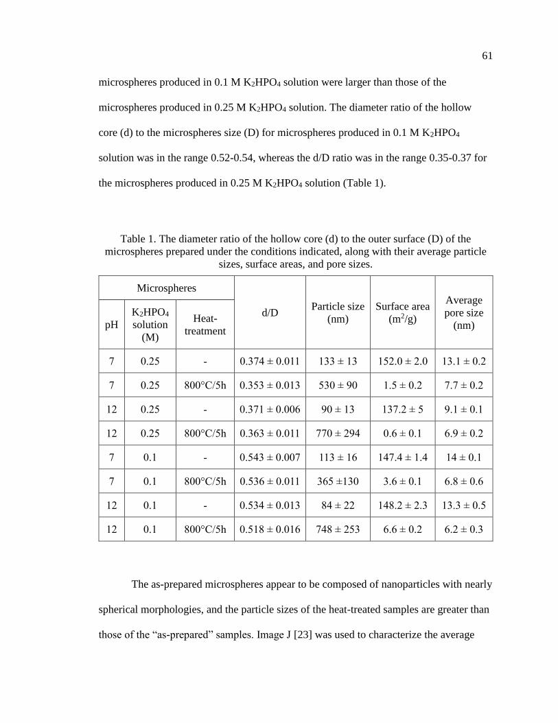
61
microspheres produced in 0.1 M K2HPO4 solution were larger than those of the
microspheres produced in 0.25 M K2HPO4 solution. The diameter ratio of the hollow
core (d) to the microspheres size (D) for microspheres produced in 0.1 M K2HPO4
solution was in the range 0.52-0.54, whereas the d/D ratio was in the range 0.35-0.37 for
the microspheres produced in 0.25 M K2HPO4 solution (Table 1).
Table 1. The diameter ratio of the hollow core (d) to the outer surface (D) of the
microspheres prepared under the conditions indicated, along with their average particle
sizes, surface areas, and pore sizes.
Microspheres
d/D Particle size
(nm)
Surface area
(m2/g)
Average
pore size
(nm) pH
K2HPO4
solution
(M)
Heat-
treatment
7 0.25 - 0.374 ± 0.011 133 ± 13 152.0 ± 2.0 13.1 ± 0.2
7 0.25 800°C/5h 0.353 ± 0.013 530 ± 90 1.5 ± 0.2 7.7 ± 0.2
12 0.25 - 0.371 ± 0.006 90 ± 13 137.2 ± 5 9.1 ± 0.1
12 0.25 800°C/5h 0.363 ± 0.011 770 ± 294 0.6 ± 0.1 6.9 ± 0.2
7 0.1 - 0.543 ± 0.007 113 ± 16 147.4 ± 1.4 14 ± 0.1
7 0.1 800°C/5h 0.536 ± 0.011 365 ±130 3.6 ± 0.1 6.8 ± 0.6
12 0.1 - 0.534 ± 0.013 84 ± 22 148.2 ± 2.3 13.3 ± 0.5
12 0.1 800°C/5h 0.518 ± 0.016 748 ± 253 6.6 ± 0.2 6.2 ± 0.3
The as-prepared microspheres appear to be composed of nanoparticles with nearly
spherical morphologies, and the particle sizes of the heat-treated samples are greater than
those of the “as-prepared” samples. Image J [23] was used to characterize the average

62
sizes of the particles that form the shell walls of the microspheres shown in Figures 2 and
3, and those values are given in Table 1. In general, the particle sizes of the as-prepared
microspheres were similar, ranging from about 80 to about 130 nm, whereas the particle
sizes of the heat-treated microspheres were significantly larger, ranging from 365 to 770
nm.
The surface areas and average pore sizes of the microspheres decreased
significantly after the heat treatments, as shown in Table 1. After heat-treatment, the
surface areas of the microspheres produced in 0.25 M K2HPO4 solution were lower (0.6
and 1.5 m2/g) than those produced in 0.1 M K2HPO4 solution (3.6 and 6.6 m2/g).
3.2. PHASE DISTRIBUTIONS AND COMPOSITIONS OF THE AS-PREPARED
AND HEAT-TREATED MICROSPHERES
Figure 4. XRD patterns from the (A) as-prepared and (B) heat-treated microspheres
produced in 0.25M K2HPO4 solution at various pH values.

63
Figure 4 shows the XRD patterns of the as-prepared and heat-treated
microspheres produced in 0.25 M KH2PO4 solutions. Similar patterns were collected
from the particles prepared in 0.1 M KH2PO4 solutions. The broad peaks in the XRD
patterns of the as-prepared microspheres may indicate that the material was poorly
crystallized, or consisted of nanometer-sized crystals, or a combination of both. These
patterns are typical for Ca-deficient hydroxyapatite (CDHA) [24, 25].The intensity of the
peaks increased markedly for the heat-treated microspheres, presumably as the result of
increased crystal fraction or crystal size. The XRD patterns of heat-treated microspheres
indicated the presence of various weight ratios of hydroxyapatite (HA) and tricalcium
phosphate (-TCP). The weight fractions of the two phases (-TCP and HA) in the heat-
treated microspheres produced in 0.25 M and 0.1 M K2HPO4 solutions are summarized in
Table 2. For the heat-treated microspheres produced in 0.25 M K2HPO4 solution, the -
TCP/HA weight ratios varied from >99/1 at pH=7 to 49/51 at pH=12. For the heat-treated
microspheres produced in 0.1 M K2HPO4 solution, the -TCP/HA ratios varied from
70/30 at pH=7 to 44/56 at pH=12.
The quantitative XRD data was used to estimate the Ca/P atomic ratios of heat-
treated microspheres from the relative fractions of -TCP (Ca/P=1.50) and HA
(Ca/P=1.67), and is compared with the Ca/P ratios determined by ICP-OES on
microspheres dissolved in nitric acid (Table 2). There is a good agreement between the
two sets of measurements.
Figure 5 shows the Ca/P values determined for as-prepared microspheres (ICP
only) and heat-treated microspheres (ICP and XRD), prepared in 0.25M and 0.1 M
KH2PO4 solutions at different values of pH. There are no significant differences in the

64
compositions of the respective as-prepared and heat-treated particles, and the Ca/P ratios
for both sets of particles increases with increasing solution pH.
Table 2. Fractions of HA and -TCP (wt%) and the Ca/P atomic ratios, from XRD and
ICP, for heat-treated microspheres produced in 0.25 M and 0.1 M K2HPO4 solutions at
various pH values.
0.25 M 0.1 M
XRD ICP XRD ICP
-TCP/HA
(wt%) Ca/P Ca/P
-TCP/HA
(wt%) Ca/P Ca/P
pH=7 >99/1 1.50 1.51 ± 0.02 70/30 1.55 1.55 ± 0.01
pH=7.5 86/14 1.52 1.51 ± 0.02 - - -
pH=8 82/18 1.53 1.53 ± 0.01 56/44 1.57 1.57 ± 0.01
pH=8.5 73/27 1.54 1.55 ± 0.02 - - -
pH=9 70/30 1.55 1.56 ± 0.01 51/47 1.58 1.58 ± 0.01
pH=10 65/35 1.56 1.57 ± 0.02 - -
pH=11 - - - 46/54 1.59 1.58 ± 0.01
pH=12 49/51 1.58 1.59 ± 0.01 44/56 1.59 1.58 ± 0.03
Therefore, based on XRD and ICP-OES analysis, we can confirm that the as-
prepared microspheres produced by glass conversion technique are CDHA microspheres,
and the heat-treated microspheres were BCP microspheres.

65
Figure 5. Ca/P ratios of as-prepared and heat-treated microspheres produced in 0.25 M
and 0.1 M K2HPO4 solutions measured by ICP-OES and estimated by XRD.
3.3. IN VITRO DEGRADATION
3.3.1. Ion Release Kinetics in Potassium Acetate Solutions. KAc solution was
chosen to evaluate the relative reactivities of the CDHA and BCP microspheres,
following procedures similar to those reported elsewhere [18, 26]. The calcium and
phosphate ions released to the KAc solution are shown in Figure 6 A and B, respectively.
Similar release kinetics were observed for each of the four sets of microspheres
evaluated, with faster ion release rates over the first ten hours of reaction, and slower
release rates thereafter. In general, the CDHA microspheres released phosphate anions at
faster rates than their respective BCP microspheres, (Figure 6B), but the fastest Ca-
release occurred from the BCP/pH=7 microspheres (Figure 6A). The Ca/P ion ratios,
released to the KAc solutions, normalized to the initial Ca/P ratios in the respective

66
particles, are shown as a function of immersion time in Figure 6 C. If this ratio equals 1,
then the particles dissolve congruently. If the ratio is less than 1, then phosphate is
preferentially released to the solution. This analysis indicates that the CDHA
microspheres (pH=7 and pH=12) dissolve congruently, at least for the first 24 hours. The
BCP (pH=7) particles, have Ca/P release ratios lower than what would be expected from
congruent dissolution. As discussed below, this can be explained by a faster dissolution
of the -TCP phase (Ca/P=1.5) in these BCP particles than the HA phase (Ca/P=1.67).
Figure 6. Time dependences of the release of (A) Ca and (B) P from different
microspheres to the KAc solution. (C) The Ca/P ion ratios released from different
microspheres to the KAc solutions.

67
3.3.2. Apatite Formation in Simulated Body Fluid. The microspheres were
immersed in SBF solution at 37°C for two weeks. The mass of each set of microspheres
initially decreased, then increased over the course of the experiment (Figure 7), an
indication of occurrence of some initial dissolution and subsequent precipitation
processes. The pH of the SBF increased slightly, from 7.4 to ~7.6, over the two-week
experiment (Figure B.3).
Figure 7. Weight changes in SBF solution at 37°C of the microspheres produced in 0.1 M
K2HPO4 solution.
Scanning electron micrographs of the surfaces of microspheres before and after
immersion in SBF solution are shown in Figure 8. After immersion, the surfaces of the
grains that constitute the structures of BCP/pH=7 and BCP/pH=12 microspheres are
covered by smaller (<100 nm) crystals and some of these smaller crystals have formed
clusters. Smaller crystals appear to have also formed on the surfaces of the CDHA

68
microspheres immersed in SBF, although these changes in surface topologies are less
obvious than they are for the BCP microspheres with their larger initial grain sizes.
Figure 9A and B shows the FTIR spectra collected from the different sets of
microspheres, before and after immersion in SBF. The absorption bands corresponding to
PO43- groups were observed in all spectra at approximately 1000-1120 cm-1 (v3), 945-970
cm-1 (v1), 550-600 cm-1 (v4), and these are consistent with the presence of apatitic phases
[27]. A peak ~875 cm-1 in the spectra from the CDHA samples is assigned to HPO42-
groups in these materials. The spectra of the CDHA samples also revealed the presence
of water (or -OH) species, including the sharp peak ~3570 cm-1 due to isolated OH
groups [27, 28], and the board peaks in the ranges 1600-1700 cm-1 and 3200-3600 cm-1,
assigned to various water vibrations [27]. The spectra from the CDHA particles also
have peaks in the range 1420-1460 cm-1 that can be assigned to the v2 modes of CO32-
[27], characteristic of the B type substitution of phosphate anions by carbonate anions in
carbonated hydroxyapatites. This carbonate component may have formed from
atmospheric CO2 dissolved in phosphate solution during the glass conversion process.
Heat treating the CDHA microspheres to create the BCP microspheres eliminates the
carbonate from the -TCP/HA structures, along with the water and the HPO42- anions.
The peaks at 974 cm-1 and 947 cm-1 assign to the phosphate mode transformed from the
peak at 962 cm-1, which indicate the presence of -TCP [27]. After immersion in SBF
solution, there is clear evidence for CO32- incorporation into the structures of all four sets
of microspheres, CDHA and BCP, indicating the formation of possible B-site carbonate-
substituted apatite.

69
Figure 8. SEM images of the external surfaces of the microspheres produced in 0.1 M
K2HPO4 solutions before (left) and after (right) two-weeks of immersion in SBF solution
at 37°C. (scale bar=500 nm)
Before After
As-
pre
par
ed
As-
pre
par
ed
Hea
t-tr
eate
d
Hea
t-tr
eate
d
pH
=7
pH
=12

70
Figure 9. FTIR (A, B) and Raman (C, D) spectra of the microspheres before and after
immersion in SBF solution for 14 days. CDHA/pH=7: (a) before and (b) after;
BCP/pH=7: (c) before and (d) after; CDHA/pH=12: (e) before and (f) after; BCP/pH=12:
(g) before and (h) after.
Figure 9C and B shows the Raman spectra collected from CDHA spheres
prepared at pH=7 and pH=12, before and after two weeks of immersion in SBF, and the
related BCP microspheres, also before and after SBF immersion. The spectra from the
CDHA microspheres are dominated by a peak at ~960 cm-1, assigned to the symmetric P-
A v2 CO
3
2 PO
4
3- PO
4
3- HPO
4
2- -OH H
2O B
D v2 PO
4
3- v
4 PO
4
3- v
1 PO
4
3- C

71
O stretching mode (v1) of PO43- species, whereas two peaks evident in the spectra from
the BCP microspheres, at 948 cm-1 and 970 cm-1, are assigned to v1 stretching modes of
the PO43- anions in -TCP [29-31]. Peaks in the ranges 570-625 cm-1 and 400-490 cm-1
are attributed to the v4 and v2 modes of PO43-, respectively. The v4 and v2 vibrational
modes of PO43- are well-separated in the spectrum for HA, whereas these two modes are
less separated in the spectrum for -TCP [30]. The low intensity, asymmetric v3
stretching mode is located in the 1000-1100 cm-1 range [32, 33].
The Raman spectra collected from the CDHA microspheres are similar to those
collected from HA, whereas the Raman spectra from the BCP microspheres are a mixture
of the characteristic spectra of HA and -TCP [30]. Moreover, the intensity of the
characteristic peak of HA at 960-962 cm-1 is relatively lower than the characteristic peaks
of -TCP at 948 cm-1 and 970 cm-1 for BCP microspheres with greater -TCP contents,
(e.g., see the XRD data in Table 2), whereas the relative intensity of the characteristic
peak of HA is greater than those for -TCP from BCP microspheres with lower contents
of -TCP.
After immersion of the BCP microspheres in SBF solution, there is an increase in
the relative intensity of the characteristic Raman peak of HA at 960-962 cm-1, compared
to the -TCP peak intensities at 948 cm-1 and 970 cm-1. This might indicate that the -
TCP phase dissolved from the BCP microspheres, to reprecipitate as nanocrystalline HA.
Finally, the low intensity peak at ~1070 cm-1, assigned to the v1 CO32- symmetric
vibrational mode, provides some additional evidence for the presence of carbonate
species in the CDHA microspheres [34, 35].

72
4. DISCUSSION
4.1. SYNTHESIS OF CDHA AND BCP MICROSPHERES
The hollow calcium phosphate microspheres formed using the borate glass
conversion technique are similar to those described in previous studies [17, 36, 37].
When the calcium ions released from the dissolving Li-Ca-borate glass exceed the local
solubility limit, they react with phosphate anions in solution to form an insoluble CDHA
phase that precipitates on the glass surface. As the glass further dissolves, the calcium
ions react with phosphate anions that diffuse through the CDHA surface layer, causing
that layer to thicken by growing inward towards the center of the microsphere. When the
glass is completely dissolved, a hollow CDHA microsphere will have formed if the initial
CaO-content of the glass is low, as it was in the present study (20 mole%). Filled CDHA
microspheres form when the initial CaO-contents are greater; e.g., 40 wt% [37].
The compositions and morphologies of the CDHA microspheres in the present
study depend on the pH and phosphate concentration of the conversion solution. For
example, the Ca/P ratio of the microspheres increases with increasing solution pH and
with lower solution phosphate concentration (Figure 5). The relative diameter of the
hollow core is greater for microspheres produced in solutions with lower phosphate
concentrations (Table 1).
Variations in CDHA composition can be understood by considering the effects of
pH on phosphate speciation in solution. For example, the phosphate anion speciation
equilibria at 25°C are given by
𝐻3𝑃𝑂4 + 𝐻2𝑂𝑝𝐾𝑎=2.21↔ 𝐻2𝑃𝑂4
− + 𝐻3𝑂+ (1)

73
𝐻2𝑃𝑂4− +𝐻2𝑂
𝑝𝐾𝑎=7.21↔ 𝐻𝑃𝑂4
2− + 𝐻3𝑂+ (2)
𝐻𝑃𝑂42− + 𝐻2𝑂
𝑝𝐾𝑎=12.67↔ 𝑃𝑂4
3− + 𝐻3𝑂+ (3)
These are the phosphate species that react with the Ca-ions released from the dissolving
Li-Ca-borate glass to precipitate CDHA. Speciation of phosphate anions in aqueous
solutions depends on pH; H2PO4- and HPO4
2- are the dominant anions in solutions with
pH<10, and PO43- anions become increasingly significant in more alkaline solutions.
Ignoring the incorporation of carbonate anions, CDHA has the general chemical formula
Ca10-x(HPO4)x(PO4)6-x(OH)2-x. The fraction of HPO42- anions incorporated in the CDHA
structure is thus related to the Ca/P according to
Ca
P=
10−𝑥
𝑥+(6−𝑥)=10−𝑥
6 (4)
From equation (3), for the pH range used in this study to prepare the CDHA
microspheres, the fraction of HPO42- anions in solution decrease with increasing pH. If
the fraction of HPO42- incorporated into the CDHA (‘x’) depends on the concentration of
HPO42- in the conversion solution, then from equation (4), the Ca/P ratio in the resulting
CDHA should increase with increasing solution pH, as shown in Figure 5. Similar
effects of solution pH on the precipitation of Ca-phosphate phases have been reported in
the literature [30, 38], where pure -TCP (Ca/P=1.5) could be obtained by precipitation
reactions from solutions with pH ~7 and subsequent heat treatments, whereas BCP
particles with increasing fractions of HA (Ca/P=1.67) were produced from particles
precipitated under more basic conditions (pH ≥ 8), followed by heat treatments.
The CDHA particles produced from the 0.25M KH2PO4 solutions generally had
lower Ca/P ratios than those produced from the 0.1M KH2PO4 solutions, particularly at

74
the lower pH values (Figure 5). That might be due to the pH changes in the 0.25M
KH2PO4 solutions caused by glass conversion were less than those in 0.1M KH2PO4
solutions. Moreover, the saturation index (SI) of precipitated hydroxyapatite is affected
by the phosphate concentration [39]. When SI>0, the precipitation occurs spontaneously.
It is reported that SI increase as phosphate concentration and pH of the solution
increase[39]. Therefore, at a certain pH of the solution, precipitation of CDHA is easier
in higher concentrated phosphate solution than in lower concentrated phosphate solution.
The relative diameters of the hollow cores in the microspheres produced in the
0.25M KH2PO4 solutions are smaller than those in the microspheres produced in the
0.1M KH2PO4 solutions (Table 1), consistent with a previous study [17]. The average
size of the individual grains on the surfaces of the CDHA microspheres and the
microsphere surface areas and nanopore sizes are similar. The lower phosphate
concentration likely leads to slower growth of calcium phosphate nuclei which may result
in more efficient packing of the calcium phosphate crystals. In addition, the nanoparticle
size observed on the external surface of the microspheres decreased from pH=7 to pH=12
for both concentrations of phosphate solutions (Table A.1). Based on some dissolution
behavior studies of borate glass [40, 41], the dissolution rate of the glass was found to be
pH-dependent. For binary Li-B glass, the glass dissolution rate decreased as the pH value
of buffer solution increased from 4 to 10 [40]. For Na-Ca-B glass in pH=4, 7 and 10
buffer solutions, the glass was found to dissolve faster in lower pH solutions [41]. We
conjectured that the dissolution rate of our Li-Ca-B glass increased as the pH value
decreased, which may lead to faster formation of calcium phosphate nuclei. In addition,
the faster dissolution of the glass may provide a higher concentration of Ca2+. The higher

75
concentration of calcium and phosphate ions may accelerate the aggregation of initial
amorphous calcium phosphate [11, 42], which may lead to a larger particle size of
calcium phosphate.
Heat-treatments have been used in previous studies of Ca-phosphate microspheres
to increase their mechanical strength [36, 43], although the development of biphasic
ceramic microspheres with different concentrations of -TCP and HA has not been
previously described. In the present study, heating the microspheres at 800 °C for 5
hours clearly transformed the CDHA to -TCP and HA. FTIR spectra (Figure 10A and
B) show the disappearance of HPO42- and CO3
2- species from the CDHA, and the
appearance of characteristic peaks of -TCP after the heat treatment. XRD (Figures 4
and 5) confirmed the formation of crystalline HA and -TCP, with fractions that
depended on the initial composition of the CDHA materials (Figure 5).
When heated above about 700°C, CDHA decomposes to stoichiometric
compounds, the relative fractions of which depend on the starting Ca/P ratio [26, 44]:
𝐶𝑎10−𝑥(𝐻𝑃𝑂4)𝑥(𝑃𝑂4)6−𝑥(𝑂𝐻)2−𝑥 →
3𝑥𝛽 − 𝐶𝑎3(𝑃𝑂4)2 + (1 − 𝑥)𝐶𝑎10(𝑃𝑂4)6(𝑂𝐻)2 + 𝑥𝐻2𝑂 (6)
When x=1 (Ca/P=1.5), the decomposition of CDHA produces -TCP, when x=0,
hydroxyapatite is produced, and when 0 < x <1 (1.5<[Ca/P]<1.67), BCP particles with
mixtures of -TCP and HA are produced. For example, CDHA particles with x=0.50,
(Ca9.5(HPO4)0.5(PO4)5.5(OH)1.5), where Ca/P=1.58, will decompose to BCP particles with
48 wt% TCP: 52 wt% HA. Therefore, the ultimate composition of the BCP particles is
tailored by controlling the pH of the phosphate solution used in the conversion process,

76
which controls the speciation of phosphate anions that react with the Ca-ions released
from the glass, and so control the Ca/P ratio of the precipitated particles.
The heat treatment not only leads to the development of the distribution of phases
that constitute the microspheres, but also affects their microstructure. The surface areas of
the microspheres decreased dramatically after the heat-treatment and the particle size in
the external surface increased after heat treatment (Table 1). In addition, the average size
of the particles that constitute the microstructures of the BCP microspheres increased
with increasing HA content.
4.2. IN VITRO DEGRADATION OF CDHA AND BCP MICROSPHERES
The in vitro degradation of calcium phosphate is affected by the composition and
microstructure (i.e. surface area, porosity, pore size) of the microspheres, and the
composition and pH of the solution. In general, the solubility of calcium phosphates in
aqueous solutions decreases in order -TCP (Ca/P=1.5, solubility at 37 °C, -
log(Ksp)=29.5) > CDHA (Ca/P=1.5~1.67, solubility at 37 °C, -log(Ksp) =~85.1)>HA
(Ca/P=1.67, solubility at 37 °C, -log(Ksp)=116.8) [5]. The comparative solubility in
acidic buffer increases in order: -TCP>CDHA>>HA [5]. A greater specific surface area
(SSA) for a particle could lead to a greater dissolution rate. In this study, the SSA of the
CDHA microspheres are significantly greater than those of the BCP microspheres (Table
1).
In the accelerated degradation test, the release profiles of the calcium and
phosphate ions from the microspheres were determined (Figure 6). The differences
between the respective release rates of calcium and phosphate ions can be related to the

77
different Ca/P ratios of the microspheres and their microstructures. Although the P-
release rates from the CDHA microspheres were generally greater than from the BCP
microspheres, this might be understood from the much greater surface areas of the former
particles (Table 1); normalized to surface area, the BCP particles are more reactive than
the CDHA particles. For the two different BCP particles tested in Figure 6, the ones with
the greater -TCP/HA ratio (pH=7, 70/30) released Ca and phosphate species at a greater
rate than the particles with the lower -TCP/HA ratio (pH=12, 44/56), consistent with
what is reported about the relative solubility of -TCP and HA ratio [26, 45]. The initial
normalized Ca/P ratio of ions released from the -TCP/HA=70/30 particles was lower
than the normalized Ca/P ratios from the other particles, indicating that the -TCP phase
was dissolving preferentially (Figure 6C).
Apatite-formation is a criterion used to evaluate the in vitro bioactivity of implant
materials [46]. When the microspheres were immersed in SBF solution, their masses at
first decreased and then increased with immersion time (Figure 7). Calcium and
phosphate ions released from the microspheres re-precipitated as nanocrystalline
hydroxyapatite particles on the surfaces of the microspheres, as indicated in the SEM
images in Figure 8. The FTIR spectra in Figure 9B are consistent with the formation of
carbonate-substituted hydroxyapatite. For BCP microspheres, the changes in the relative
intensities of characteristic Raman peak of HA at 960-962 cm-1 to the -TCP peak
intensities at 948 cm-1 and 970 cm-1 after SBF immersion indicates the dissolution of -
TCP phase from the BCP microspheres and the reprecipitation of HA (Figure 9D). More
apatite formation was observed on the surfaces of BCP microspheres with 70wt% -TCP
content than the BCP microspheres with 44wt% -TCP (Figure B.5).
78
5. CONCLUSIONS
This study demonstrated that hollow BCP microspheres could be produced by the
heat-treatment of CDHA microspheres obtained by the glass conversion technique. The
composition and microstructure of the microspheres was affected by the concentration
and pH value of the phosphate solution in glass conversion process. Two sets of CDHA
microspheres (Ca/P ≈ 1.55 and 1.59) and the corresponding BCP microspheres (-
TCP/HA=70/30 and 44/56were selected for further in vitro tests. The BCP microspheres
with 70wt% -TCP showed faster degradation rates in acetic acid and converted more
quickly to HA in simulated body fluids. The ability to tailor the composition, nano-
structure, and meso-structure of these microspheres by controlling the processing
conditions to convert the Li-Ca-B glasses in phosphate solutions means that materials can
be designed for specific biomedical applications that utilize the macro-porosity of the
hollow microspheres, the nano-porosity of the shell walls, and the enhanced bio-activity
of the BCP phases.
ACKNOWLEDGEMENT
We are grateful for the technical support of colleagues in the Missouri S&T
Materials Research Center and for the financial support of the Lasko Endowment in the
Department of Materials Science and Engineering.

79
REFERENCES
[1] J.C. Elliott, Structure and chemistry of the apatites and other calcium
orthophosphates. Vol. 18. 2013: Elsevier.
[2] R.Z. Legeros, Apatites in biological systems. Progress in crystal growth and
characterization, 1981. 4(1-2): p. 1-45.
[3] C. Rey, V. Renugopalakrishman, B. Collins, and M.J. Glimcher, Fourier
transform infrared spectroscopic study of the carbonate ions in bone mineral
during aging. Calcified tissue international, 1991. 49(4): p. 251-258.
[4] R.Z. LeGeros, Calcium phosphate-based osteoinductive materials. Chemical
Reviews, 2008. 108(11): p. 4742-4753.
[5] N. Eliaz and N. Metoki, Calcium phosphate bioceramics: A review of their
history, structure, properties, coating technologies and biomedical applications.
Materials, 2017. 10(4): p. 334.
[6] W. Wang and K.W.K. Yeung, Bone grafts and biomaterials substitutes for bone
defect repair: A review. Bioactive Materials, 2017. 2(4): p. 224-247.
[7] E. García-Gareta, M.J. Coathup, and G.W. Blunn, Osteoinduction of bone
grafting materials for bone repair and regeneration. Bone, 2015. 81: p. 112-121.
[8] V. Campana, G. Milano, E. Pagano, M. Barba, C. Cicione, G. Salonna, W.
Lattanzi, and G. Logroscino, Bone substitutes in orthopaedic surgery: from basic
science to clinical practice. Journal of Materials Science: Materials in Medicine,
2014. 25(10): p. 2445-2461.
[9] C. Laurencin, Y. Khan, and S.F. El-Amin, Bone graft substitutes. Expert review
of medical devices, 2006. 3(1): p. 49-57.
[10] M. Bohner and J. Lemaitre, Can bioactivity be tested in vitro with SBF solution?
Biomaterials, 2009. 30(12): p. 2175-2179.
[11] S.V. Dorozhkin, Calcium orthophosphates (CaPO4): occurrence and properties.
Progress in Biomaterials, 2016. 5(1): p. 9-70.
[12] I.R. Gibson, I. Rehman, S.M. Best, and W. Bonfield, Characterization of the
transformation from calcium-deficient apatite to β-tricalcium phosphate. Journal
of Materials Science: Materials in Medicine, 2000. 11(12): p. 799-804.

80
[13] K.-R. Kang, Z.-G. Piao, J.-S. Kim, I.-A. Cho, M.-J. Yim, B.-H. Kim, J.-S. Oh,
J.S. Son, C.S. Kim, and D.K. Kim, Synthesis and Characterization of β-
Tricalcium Phosphate Derived From Haliotis sp. Shells. Implant dentistry, 2017.
26(3): p. 378-387.
[14] J. Tao, H. Pan, H. Zhai, J. Wang, L. Li, J. Wu, W. Jiang, X. Xu, and R. Tang,
Controls of tricalcium phosphate single-crystal formation from its amorphous
precursor by interfacial energy. Crystal Growth and Design, 2009. 9(7): p. 3154-
3160.
[15] W. Huang, D.E. Day, and M.N. Rahaman, Conversion of tetranary borate glasses
to phosphate compounds in aqueous phosphate solution. Journal of the American
Ceramic Society, 2008. 91(6): p. 1898-1904.
[16] N.N. Vanderspiegel, Reaction of potassium calcium borate glasses to form apatite
and dicalcium phosphate dihydrate. Masters Theses, Missouri University of
Science and Technology, 2004.
[17] H. Fu, M.N. Rahaman, and D.E. Day, Effect of process variables on the
microstructure of hollow hydroxyapatite microspheres prepared by a glass
conversion method. Journal of the American Ceramic Society, 2010. 93(10): p.
3116-3123.
[18] W. Xiao, B. Sonny Bal, and M.N. Rahaman, Preparation of resorbable
carbonate-substituted hollow hydroxyapatite microspheres and their evaluation in
osseous defects in vivo. Materials Science & Engineering C, 2016. 60: p. 324-332.
[19] H. Fu, M.N. Rahaman, D.E. Day, and W. Huang, Effect of pyrophosphate ions on
the conversion of calcium–lithium–borate glass to hydroxyapatite in aqueous
phosphate solution. Journal of Materials Science: Materials in Medicine, 2010.
21(10): p. 2733-2741.
[20] Y. Gu, W. Xiao, L. Lu, W. Huang, M.N. Rahaman, and D. Wang, Kinetics and
mechanisms of converting bioactive borate glasses to hydroxyapatite in aqueous
phosphate solution. Journal of Materials Science, 2011. 46(1): p. 47-54.
[21] Y. Shen, J.A. Semon, and R.K. Brow, Hollow biphasic calcium phosphate
microspheres from glass dissolution and reprecipitation; Part II: In vivo Studies
of Bone Regeneration and Blood Vessel Formation.
[22] T. Kokubo, H. Kushitani, S. Sakka, T. Kitsugi, and T. Yamamuro, Solutions able
to reproduce in vivo surface‐structure changes in bioactive glass‐ceramic A‐W3.
Journal of biomedical materials research, 1990. 24(6): p. 721-734.

81
[23] A. Mazzoli and O. Favoni, Particle size, size distribution and morphological
evaluation of airborne dust particles of diverse woods by Scanning Electron
Microscopy and image processing program. Powder Technology, 2012. 225: p.
65-71.
[24] K.A. Gross, J. Andersons, M. Misevicius, and J. Svirksts, Traversing phase fields
towards nanosized beta tricalcium phosphate. Key Engineering Materials, 2014.
587: p. 97-100.
[25] N. Varadarajan, R. Balu, D. Rana, M. Ramalingam, and T. Kumar, Accelerated
sonochemical synthesis of calcium deficient hydroxyapatite nanoparticles:
structural and morphological evolution. Journal of Biomaterials and Tissue
Engineering, 2014. 4(4): p. 295-299.
[26] R.Z. LeGeros, S. Lin, R. Rohanizadeh, D. Mijares, and J.P. LeGeros, Biphasic
calcium phosphate bioceramics: preparation, properties and applications.
Journal of Materials Science: Materials in Medicine, 2003. 14(3): p. 201-209.
[27] L. Berzina-Cimdina and N. Borodajenko, Research of calcium phosphates using
Fourier transform infrared spectroscopy, in Infrared Spectroscopy-Materials
Science, Engineering and Technology. 2012, IntechOpen.
[28] A. Destainville, E. Champion, D. Bernache-Assollant, and E. Laborde, Synthesis,
characterization and thermal behavior of apatitic tricalcium phosphate. Materials
Chemistry and Physics, 2003. 80(1): p. 269-277.
[29] P. De Aza, F. Guitian, C. Santos, S. De Aza, R. Cusco, and L. Artus, Vibrational
properties of calcium phosphate compounds. 2. Comparison between
hydroxyapatite and β-tricalcium phosphate. Chemistry of Materials, 1997. 9(4):
p. 916-922.
[30] F. Bakan, A Systematic Study of the Effect of pH on the Initialization of Ca-
deficient Hydroxyapatite to β-TCP Nanoparticles. Materials (Basel, Switzerland),
2019. 12(3): p. 354.
[31] D.-H. Kim, K.-H. Hwang, J.D. Lee, H.-C. Park, and S.-Y. Yoon, Long and short
range order structural analysis of in-situ formed biphasic calcium phosphates.
Biomaterials Research, 2015. 19(1): p. 14.
[32] P. Ducheyne, Comprehensive biomaterials II. 2017: Elsevier.
[33] T.R. Machado, J.C. Sczancoski, H. Beltrán-Mir, M.S. Li, J. Andrés, E.
Cordoncillo, E. Leite, and E. Longo, Structural properties and self-activated
photoluminescence emissions in hydroxyapatite with distinct particle shapes.
Ceramics International, 2018. 44(1): p. 236-245.

82
[34] A. Awonusi, M.D. Morris, and M.M.J. Tecklenburg, Carbonate Assignment and
Calibration in the Raman Spectrum of Apatite. Calcified Tissue International,
2007. 81(1): p. 46-52.
[35] L. Borkowski, A. Sroka-Bartnicka, P. Drączkowski, A. Ptak, E. Zięba, A.
Ślósarczyk, and G. Ginalska, The comparison study of bioactivity between
composites containing synthetic non-substituted and carbonate-substituted
hydroxyapatite. Materials Science and Engineering: C, 2016. 62: p. 260-267.
[36] Q. Wang, W. Huang, D. Wang, B.W. Darvell, D.E. Day, and M.N. Rahaman,
Preparation of hollow hydroxyapatite microspheres. Journal of Materials Science:
Materials in Medicine, 2006. 17(7): p. 641-646.
[37] K.P. Fears, Formation of hollow hydroxyapatite microspheres. Masters Theses,
Missouri University of Science and Technology, 2001.
[38] K. Salma, L. Berzina-Cimdina, and N. Borodajenko, Calcium phosphate
bioceramics prepared from wet chemically precipitated powders. Processing and
Application of Ceramics, 2010. 4(1): p. 45-51.
[39] Y. Song, H.H. Hahn, and E. Hoffmann, Effects of solution conditions on the
precipitation of phosphate for recovery: A thermodynamic evaluation.
Chemosphere, 2002. 48(10): p. 1029-1034.
[40] M.H. Veléz, H.L. Tuller, and D.R. Uhlmann, Chemical durability of lithium
borate glasses. Journal of Non-Crystalline Solids, 1982. 49(1): p. 351-362.
[41] J.D. Lowry, Dissolution behavior of alkali borate glasses. Masters Theses,
Missouri University of Science and Technology, 2002.
[42] V. Čadež, I. Erceg, A. Selmani, D.D. Jurašin, S. Šegota, D.M. Lyons, D. Kralj,
and M. Dutour Sikirić, Amorphous calcium phosphate formation and aggregation
process revealed by light scattering techniques. Crystals, 2018. 8(6): p. 254.
[43] H. Fu, M.N. Rahaman, D.E. Day, and R.F. Brown, Hollow hydroxyapatite
microspheres as a device for controlled delivery of proteins. Journal of Materials
Science: Materials in Medicine, 2011. 22(3): p. 579-591.
[44] S.-C. Liou and S.-Y. Chen, Transformation mechanism of different chemically
precipitated apatitic precursors into β-tricalcium phosphate upon calcination.
Biomaterials, 2002. 23(23): p. 4541-4547.

83
[45] M. Ebrahimi, M.G. Botelho, and S.V. Dorozhkin, Biphasic calcium phosphates
bioceramics (HA/TCP): Concept, physicochemical properties and the impact of
standardization of study protocols in biomaterials research. Materials Science &
Engineering C, 2017. 71: p. 1293-1312.
[46] T. Kokubo and H. Takadama, How useful is SBF in predicting in vivo bone
bioactivity? Biomaterials, 2006. 27(15): p. 2907-2915.
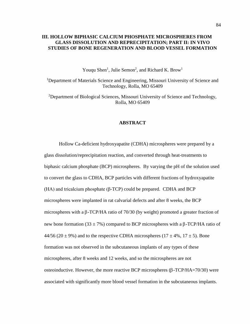
84
III. HOLLOW BIPHASIC CALCIUM PHOSPHATE MICROSPHERES FROM
GLASS DISSOLUTION AND REPRECIPITATION; PART II: IN VIVO
STUDIES OF BONE REGENERATION AND BLOOD VESSEL FORMATION
Youqu Shen1, Julie Semon2, and Richard K. Brow1
1Department of Materials Science and Engineering, Missouri University of Science and
Technology, Rolla, MO 65409
2Department of Biological Sciences, Missouri University of Science and Technology,
Rolla, MO 65409
ABSTRACT
Hollow Ca-deficient hydroxyapatite (CDHA) microspheres were prepared by a
glass dissolution/reprecipitation reaction, and converted through heat-treatments to
biphasic calcium phosphate (BCP) microspheres. By varying the pH of the solution used
to convert the glass to CDHA, BCP particles with different fractions of hydroxyapatite
(HA) and tricalcium phosphate (β-TCP) could be prepared. CDHA and BCP
microspheres were implanted in rat calvarial defects and after 8 weeks, the BCP
microspheres with a -TCP/HA ratio of 70/30 (by weight) promoted a greater fraction of
new bone formation (33 ± 7%) compared to BCP microspheres with a -TCP/HA ratio of
44/56 (20 ± 9%) and to the respective CDHA microspheres (17 ± 4%, 17 ± 5). Bone
formation was not observed in the subcutaneous implants of any types of these
microspheres, after 8 weeks and 12 weeks, and so the microspheres are not
osteoinductive. However, the more reactive BCP microspheres (-TCP/HA=70/30) were
associated with significantly more blood vessel formation in the subcutaneous implants.

85
1. INTRODUCTION
Over the past several decades, calcium phosphate materials have been developed
for clinical applications to promote regeneration in osteo-defects [1-3]. In particular,
biphasic calcium phosphate (BCP) materials that combine hydroxyapatite (HA) and -
tricalcium phosphate (-TCP) phases have served as bone graft substitutes in orthopedics
[4-7].
In general, HA is poorly bioresorbable, whereas -TCP is more bioresorbable and
can be replaced by new bone at faster rates [3, 6, 7]. Therefore, the chemical properties of
BCP materials can be tailored by the relative concentrations of the individual phases [2,
4, 6-8]. The Ca/P atomic ratios in BCP materials range from 1.5 for pure -TCP to 1.67
for pure HA. BCP ceramics have been used to produce biocompatible scaffolds, where
the level of bioactivity, bioresorbability, osteoconductivity, and osteoinductivity could be
adjusted by varying the -TCP/HA ratio [4-7]. Various BCP products with different -
TCP/HA ratios have been evaluated in large number of studies, but there is no agreement
on the optimal -TCP/HA ratio for clinical applications [6].
Previous studies [9-11] have shown that the hollow HA microspheres alone have
limited capacity for bone regeneration, likely because they were composed of chemically
stable HA or CDHA. In Part I of this study [12], CDHA microspheres were produced by
a glass conversion technique and hollow BCP microspheres with different -TCP/HA
ratios were produced by heat-treating the CDHA microspheres. The composition and
microstructure of the microspheres was affected by the concentration and pH value of the
phosphate solution used in the glass conversion process.

86
The objective of the present paper is to characterize the in vivo performance of the
hollow CDHA and BCP microspheres. CDHA microspheres with different Ca/P ratios
produce BCP microspheres with different β-TCP/HA ratios. The microspheres were
implanted in rat calvarial defects for 8 weeks and subcutaneous defects for 8 and 12
weeks, and their bioactive performances were evaluated.
2. MATERIALS AND METHODS
2.1. PREPARATION AND CHARACTERIZATION OF HOLLOW BIPHASIC
CALCIUM PHOSPHATE MICROSPHERES
The preparation of CDHA and BCP microspheres used here is described in Part I
of this study [12]. Briefly, hollow CDHA microspheres were prepared by reacting glass
microspheres (composition 11Li2O, 15CaO and 74B2O3 (wt%), 150- 250 μm in diameter)
in 0.1 M K2HPO4 solutions with pH values of 7 and 12 at 37°C for 4 days. The
converted microspheres were washed with distilled water and anhydrous ethanol, and
then dried at room temperature for at least 12 h, and at 90 °C for at least 12 h. After
conversion, some of the CDHA microspheres were converted to BCP microspheres by
heating them in a platinum dish in air at 800°C for 5 hours.
Table 1 lists the properties of the hollow microspheres used in this study. Samples
prepared in a phosphate solution with a pH of 7 had Ca/P atomic ratios of 1.55 and after
the heat treatment, converted to BCP microspheres with an β-TCP/HA ratio of 70/30 (by
weight), whereas samples prepared in a phosphate solution with a pH of 12 had Ca/P
atomic ratios of 1.59 and after the heat treatment, converted to BCP microspheres with a

87
β-TCP/HA ratio of 44/56. Prior to implantation, all microspheres were sterilized by
immersing in anhydrous ethanol and then exposing them to ultraviolet light for 15 min.
2.2. IN VIVO STUDIES OF CDHA AND BCP MICROSPHERES
All animal use and care procedures were approved by the Missouri S&T
Institutional Animal Care and Use Committee in compliance with the NIH Guide for
Care and Use of Laboratory Animals (1985). Male Sprague-Dawley (SD) rats, three
months old, were used. Before surgery, the animals were acclimated for two weeks to
diet, water, and housing under a 12 h/12 h light/dark cycle. The rats were anesthetized
with a combination of isoflurane and oxygen. The surgery area on each animal was
shaved, scrubbed with 70% ethanol and iodine, and draped. Calvarial defects and
subcutaneous defects were implanted with one of the four groups of microspheres
described in the previous section. The microspheres were sterilized by immersing in
anhydrous ethanol and then exposing them to ultraviolet light for 15 min, prior to
implantation.
2.2.1. Calvarial Defects. For the calvarial defects, sterile instruments and aseptic
techniques were used to create a 1 cm cranial skin incision in an anterior-to-posterior
direction along the midline. The subcutaneous tissue, musculature and periosteum were
dissected and reflected to expose the calvaria. Bilateral full thickness defects (4.6 mm in
diameter) were created in the central area of each parietal bone using a saline-cooled
trephine drill. The sites were constantly irrigated with sterile phosphate-buffered saline to
prevent overheating of the bone margins and to remove the bone debris. Each defect was
randomly implanted with 10 mg of microspheres from each group listed in Table 1. After

88
the implantation of the microspheres, one drop of Ringer’s solution was added to each
defect. The periosteum and skin were repositioned and closed with wound clips. Each
animal received an intramuscular injection of ~200 μl buprenorphine and ~200 μl
penicillin post-surgery. All animals were monitored daily for the condition of the surgical
wound, food intake, activity and clinical signs of infection. After 8 weeks, the animals
were sacrificed by CO2 inhalation, and the calvarial defect sites with surrounding bone
and soft tissue were harvested for subsequent evaluations.
2.2.2. Subcutaneous Defects. For the subcutaneous implants, the microspheres
were implanted at random implant sites to remove any bias from a single rat. Each rat had
four implant sites, two inferior to the shoulders and two superior to the hind legs. An
incision approximately 2 cm in length was made completely through the dermal tissue
perpendicular to the spine with a pair of SuperCut surgical scissors. Then, a skin retractor
was gently inserted into the incision to create a pocket between the cutaneous tissue and
the skeletal muscle. Each pocket was randomly implanted with 20 mg of the
microspheres from each group listed in Table 1, and the skin was then closed with wound
clips. All rats received the same post-surgery care and monitoring as those in the calvarial
implantation study. At the predetermined time points (8 weeks or 12 weeks), the animals
were sacrificed and the subcutaneous defect sites with surrounding soft tissue were
harvested for subsequent evaluations.
2.2.3. Histological Processing. Harvested calvarial samples and subcutaneous
samples were fixed in a 10% neutral buffer formalin solution for five days. All samples
were cut in the middle after being washed with deionized water. The samples were
decalcified in 14 wt% ethylenediaminetetraacetic acid (Sigma-Aldrich, USA) for 2

89
weeks, dehydrated in ethanol, and then embedded in paraffin using standard histological
techniques. These samples were sectioned using a microtome (Leica RM 2235,
Germany). The thickness of the tissue section with paraffin was 5 μm. These slices were
then stained with hematoxylin and eosin (H&E).
2.2.4. Histomorphometric Analysis. The stained sections were viewed using an
optical microscope (KH-8700, Hirox-USA) and analyzed by Image J software (National
Institutes of Health, USA).
For calvarial samples, the percentages of new bone and residual microspheres in
the defect were evaluated from the H&E stained sections. The total defect area was
measured from one edge of the old calvarial bone, including the entire implant and tissue
within it, to the other edge of the old bone. The newly formed bone and residual
microspheres within this area were then outlined and measured. The amount of the new
bone formation and residual microspheres were expressed as a percentage of the total
defect area.
For subcutaneous samples, the blood vessels and foreign body giant cells were
examined based on the H&E stained sections. The total defect area containing all the
microspheres and tissue within them was identified, and blood vessels and foreign body
giant cells were outlined, measured, and presented as a percentage of the total defect area.
2.3. STATISTICAL ANALYSIS
Measurements of the percentage of new bone or blood vessel formation (relative
to the entire defect area) were expressed as a mean ± SD. Analysis for differences

90
between groups was performed using one-way analysis of variance (ANOVA) followed
by the Tukey’s post hoc test; the differences were considered significant at p < 0.05.
3. RESULTS
3.1. HOLLOW CA-PHOSPHATE MICROSPHERES
Figure 1. Electron micrographs of the cross-sections (left), external surfaces (center) and
internal surfaces (right) of the CDHA and BCP hollow microspheres used in this study;
from [12].

91
Table 1. Microspheres used for in vivo tests (rat calvarial implantation and subcutaneous
implantation); compositions and properties are from [12].
Group
Microspheres
pH Heat-
treatment
Phase
(wt%)
Ca/P
atomic
ratio
Surface
Area (m2/g)
Pore size
(nm)
Sample
size (n)
1 7 - CDHA ~1.55 147.4 ± 1.4 14 ± 0.1 6
2 7 800 °C /
5h 70 -TCP
30 HA ~1.55 3.6 ± 0.1 6.8 ± 0.6 6
3 12 - CDHA ~1.59 148.2 ± 2.3 148.2 ± 2.3 6
4 12 800 °C /
5h 44 -TCP
56 HA ~1.59 6.6 ± 0.2 6.6 ± 0.2 6
Figure 1 shows representative scanning electron microscopic images of the
CDHA and BCP microspheres used in this study, and Table 1 lists some of their
properties [12]. The diameter ratios of hollow core to outer surface were ~0.53. Samples
prepared in a phosphate solution with a pH of 7 had Ca/P atomic ratios of 1.55, and after
the heat treatment, converted to BCP microspheres with an β-TCP/HA ratio of 70/30 (by
weight), whereas samples prepared in a phosphate solution with a pH of 12 had Ca/P
atomic ratios of 1.59, and after the heat treatment, converted to BCP microspheres with
an β-TCP/HA ratio of 44/56. The CDHA microspheres are formed from particles about
100 nm in diameter [12] that form high surface areas (about 150 m2/g) with nanoporosity
(Table 1). After heat treatments, the CDHA particles transform to larger β-TCP and HA
grains, and there is a substantial loss of surface area (4-7 m2/g), although the walls retain
nanoporosity (Table 1).

92
3.2. CALVARIAL IMPLANTATION
Figure 2. Optical images of H&E stained sections of rat calvarial defects implanted with
four groups of microspheres at 8 weeks. (A1) CDHA/pH=7; (B1) BCP/pH=7; (C)
CDHA/pH=12; (D) BCP/pH=12. (A2-D2) Higher-magnification images of outlined
areas in (A1-D1). HB=host bone; NB=new bone.
H&E stained sections from the rat calvarial defects implanted with four groups of
microspheres after 8 weeks are shown in Figure 2. The areal fractions of new bone
NB NB NB
HB HB
NB
NB NB HB
HB
NB
NB NB HB
NB
NB NB
HB 1 mm
HB
A1
B1
C1
D1
100 μm NB
NB
NB
NB NB
NB NB
A2
B2
C2
D2

93
formation and residual microspheres are summarized in Table 2. In general, the fractions
of residual microspheres remaining increased in the order (BCP/pH=7) < (BCP/pH=12) <
(CDHA/pH=7) = (CDHA/pH=12), whereas new bone formation increased in the opposite
order (CDHA/pH=7) = (CDHA/pH=12) < (BCP/pH=12) < (BCP/pH=7).
Table 2. Summary of areal fractions of new bone formation and residual microspheres in
rat calvarial defects 8 weeks after implantation.
Implant type Percent new bone (%) Percent residual microspheres (%)
CDHA/pH=7 17 ± 4 31 ± 6
BCP/pH=7 33 ± 7 23 ± 4
CDHA/pH=12 17 ± 5 32 ± 6
BCP/pH=12 20 ± 9 29 ± 3
Figure 3A presents the data from Table 2 and shows that after eight weeks of
implantation, the fraction of new bone formation associated with the BCP/pH=7 (70 wt%
-TCP) microspheres was statistically greater than what formed around the other
implants (n = 6, p < 0.05, Figure 3A). For the CDHA microspheres and BCP/pH=12 (44
wt% -TCP) microspheres, the new bone growth was limited to the periphery of the
defects (edges and the bottom of the defects), and connective tissue filled the majority of
these defects (Figure 2). There was no significant difference in new bone formation
between these three groups (n = 6, p > 0.05).

94
Figure 3. A comparison of A) new bone formation, and B) residual microspheres, as a
percentage of the total defect area, in rat calvarial defects implanted with four group of
microspheres at 8 weeks. (Mean ± SD; n = 6, * significant difference between groups; p <
0.05).
Figure 2 shows that residual microspheres remain in the calvarial defects after
eight weeks implantation, and Figure 3B shows the respective cross-sectional areas of
those microspheres. The areal fraction of residual BCP/pH=7 microspheres was
significantly lower (n = 6, p < 0.05) than the residual fractions of the other three samples,
and the enhanced in vivo reactivity of these particles is consistent with the greater fraction
A
B

95
of new bone formation around these particles. In fact, Figure 2B1 and B2 show that new
bone or fibrous tissue has infiltrated into the hollow core of a number of the BCP/pH=7
microspheres, additional evidence for the enhanced reactivity of these particles.
3.3. SUBCUTANEOUS IMPLANTATION
Figure 4. Optical images of H&E stained sections of rat subcutaneous defects implanted
with four groups of microspheres at 8 weeks. (A) CDHA/pH=7; (B) BCP/pH=7; (C)
CDHA/pH=12; (D) BCP/pH=12. Green arrows indicate multinuclear cells, yellow arrows
indicate blood vessels.
The H&E stained sections of subcutaneous defects implanted with the four groups
of microspheres are shown in Figure 4 after implantation for 8 weeks and in Figure 5,
after 12 weeks. No new bone formation was observed around any of these implants and
so there is no evidence for osteoinductivity by these CDHA and BCP microspheres. Cell

96
nuclei are blue, cytoplasm connective tissue and extra cellular matrix are purple or red,
and red blood cells are bright red. The microspheres from all four groups are surrounded
by connective tissue, some giant multinuclear cells (green arrows) and blood vessels
(yellow arrows). Larger numbers of blood vessels and giant multinuclear cells are
associated with the BCP microspheres than with the associated CDHA microspheres. The
biodegradation rates of the BCP microspheres appear to be faster than the CDHA
microspheres. Moreover, the BCP/pH=7 microspheres appear to have degraded faster
than BCP/pH=12 microspheres.
Figure 5. Optical images of H&E stained sections of rat subcutaneous defects implanted
with four groups of microspheres at 12 weeks. (A) CDHA/pH=7; (B) BCP/pH=7; (C)
CDHA/pH=12; (D) BCP/pH=12. Green arrows indicate multinuclear cells, yellow arrows
indicate blood vessels.

97
Table 3. Summary of the areal fractions of blood vessels and foreign body giant cells in
rat subcutaneous defects implanted with four groups of microspheres after 8 weeks and
12 weeks.
Implant Blood vessels
(%)
Foreign body giant
cells (%)
Implantation time
(weeks)
CDHA/pH=7
0.41 ± 0.22 0.48 ± 0.21 8
0.49 ± 0.17 0.16 ± 0.08 12
BCP/pH=7
1.27 ± 0.36 1.09 ± 0.35 8
1.43 ± 0.38 0.69 ± 0.28 12
CDHA/pH=12
0.32 ± 0.13 0.29 ± 0.09 8
0.64 ± 0.28 0.19 ± 0.05 12
BCP/pH=12
0.64 ± 0.16 0.78 ± 0.33 8
0.79 ± 0.28 0.38 ± 0.20 12
The percent area of blood vessels and foreign body giant cells in rat subcutaneous
defects implanted for 8 weeks and 12 weeks with the microspheres from the four groups
are summarized in Table 3. At 8 weeks, the areal fractions of blood vessels associated
with the BCP microspheres are significantly enhanced relative to their respective CDHA
microspheres (n = 6, p < 0.05, Figure 6A); the fraction of blood vessels formed in
BCP/pH=7 microspheres was greater than those with the BCP/pH=12 microspheres,
although the difference was not significant (n = 6, p > 0.05). After 12-weeks
implantation, blood vessel formation increased for all groups compared to the 8-weeks
implantation, although the increases were not significant (n = 6, p > 0.05). The area
around the BCP/pH=7 microspheres had significantly more blood vessels than the areas

98
around the microspheres in other three groups (n = 6, p < 0.05). Furthermore, there was
no significant difference in the formation of blood vessels between CDHA groups and
BCP/pH=12 microspheres (n = 6, p > 0.05).
Figure 6. Comparative areal fractions of blood vessels and foreign body giant cells in
implants with the four groups of microspheres after 8 weeks and 12 weeks in rat
subcutaneous defects (Mean ± SD; n = 6, * significant difference between groups; p <
0.05).
A
B

99
Figure 6B shows that after eight weeks in the sub-cutaneous implants, the areal
fractions of foreign body giant cells associated with the BCP microspheres were
significantly greater than those associated with their respective CDHA microspheres (n =
6, p < 0.05). There was no significant difference in the presence of foreign body giant
cells between the two BCP groups, and no significant difference between the two CDHA
groups, as well. The fractions of foreign body giant cells decreased between 8 weeks and
12 weeks for all four groups, significantly for the CDHA/pH=7 and BCP/pH=12
microspheres. Additionally, the foreign body giant cells associated with the BCP/pH=7
microspheres were significantly greater than those associated with the other three groups.
4. DISCUSSION
4.1. IN VIVO DEGRADATION
The response of a body to the implantation of calcium phosphate materials
includes the diffusion of biological fluid and then cellular colonization. The cells for
bioresorption include monocytes, macrophages, giant cells, osteoclasts, and fibroblast,
and the cells for tissue repair include osteogenic cells [2, 4, 13]. Therefore, for the in vivo
studies, cell-mediated degradation also needs to be considered. The chemical properties
of calcium phosphate materials, such as solubility, influence the bioresorption ability. For
BCP, the resorption activity is influenced by the ratio of -TCP/HA [4, 5, 14]. In general,
the greater the ratio of -TCP/HA, the greater the bioresorption ability. This was
confirmed in Part 1 of this study, where it was shown that the BCP microspheres with 70
wt% -TCP dissolved faster in an acetic acid solution than the BCP microspheres with 44

100
wt% -TCP, and both dissolved faster than the respective CDHA microspheres, despite
the much greater surface areas of the latter [12]. The bioresorption of the calcium
phosphate is mainly regulated by osteoclasts in calvarial defects and macrophages in
subcutaneous defects. The osteoclasts, a type of bone cell, are involved in the
maintenance, repair and remodeling of the skeleton. These cells are able to release small
amounts of hydrochloric acid at material surfaces leading to a local pH change and the
dissolution of calcium phosphate [15].
In the in vivo studies, in both the calvarial defects and subcutaneous defects, it is
clear that the BCP microspheres with 70 wt% -TCP degraded faster than the other
groups of microspheres (Figures 2, 4 and 5). For example, the residual fraction of
microspheres in the calvarial defects implanted with BCP microspheres with 70 wt% -
TCP was significantly lower than those of other groups (Figure 3B). In the subcutaneous
defects, there was a greater number of foreign body giant cells associated with the same
group of BCP microspheres with 70 wt% -TCP (Figure 6B). The foreign body giant
cells are a collection of fused macrophages that respond to the biomaterials [16]. The
macrophages fused together to form giant cells at the biomaterial interface to digest the
microspheres.
4.2. BONE REGENERATION IN VIVO
4.2.1. Bone Regeneration in Calvarial Defects. The great interest in the use of
BCP (-TCP/HA) materials for bone regeneration is based on the preferential dissolution
of the -TCP phase. By adjusting the -TCP/HA ratio, the resorption rate of the implant,
and its replacement by new bone, can be controlled [6, 7]. In the present study, bone
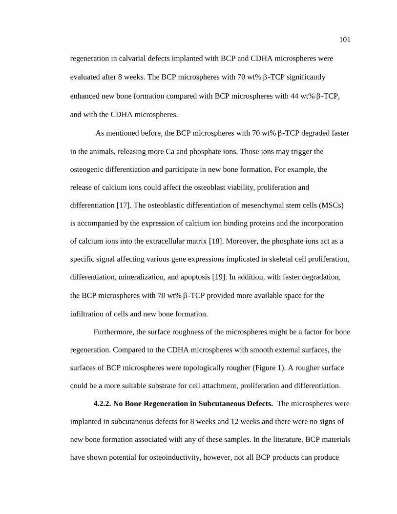
101
regeneration in calvarial defects implanted with BCP and CDHA microspheres were
evaluated after 8 weeks. The BCP microspheres with 70 wt% -TCP significantly
enhanced new bone formation compared with BCP microspheres with 44 wt% -TCP,
and with the CDHA microspheres.
As mentioned before, the BCP microspheres with 70 wt% -TCP degraded faster
in the animals, releasing more Ca and phosphate ions. Those ions may trigger the
osteogenic differentiation and participate in new bone formation. For example, the
release of calcium ions could affect the osteoblast viability, proliferation and
differentiation [17]. The osteoblastic differentiation of mesenchymal stem cells (MSCs)
is accompanied by the expression of calcium ion binding proteins and the incorporation
of calcium ions into the extracellular matrix [18]. Moreover, the phosphate ions act as a
specific signal affecting various gene expressions implicated in skeletal cell proliferation,
differentiation, mineralization, and apoptosis [19]. In addition, with faster degradation,
the BCP microspheres with 70 wt% -TCP provided more available space for the
infiltration of cells and new bone formation.
Furthermore, the surface roughness of the microspheres might be a factor for bone
regeneration. Compared to the CDHA microspheres with smooth external surfaces, the
surfaces of BCP microspheres were topologically rougher (Figure 1). A rougher surface
could be a more suitable substrate for cell attachment, proliferation and differentiation.
4.2.2. No Bone Regeneration in Subcutaneous Defects. The microspheres were
implanted in subcutaneous defects for 8 weeks and 12 weeks and there were no signs of
new bone formation associated with any of these samples. In the literature, BCP materials
have shown potential for osteoinductivity, however, not all BCP products can produce

102
new bone formation in non-osseous defects [6]. The osteoinduction phenomenon of BCPs
is affected on the animal species. The observation of osteoinduction has been frequently
reported in large animals[20-24], such as goats, pigs, dogs, while rarely in small animals
[24-26], such as rabbits, mice, and rats until 120 days. Our microspheres of BCP or
CDHA did not induce any new bone in the rat subcutaneous defects within 12 weeks.
This is accordance with the previous in vivo studies using rats [24, 27].
4.3. BLOOD VESSEL FORMATION IN SUBCUTANEOUS DEFECTS
For subcutaneous implantation, blood vessel formation increased between 8
weeks and 12 weeks for all groups of microspheres, and more blood vessels were formed
in the defects implanted with BCP microspheres than CDHA microspheres (Figure 6A).
BCP microspheres with faster degradation rates could provide more calcium ions, which
play an important role in angiogenesis [28]. The BCP microspheres were also associated
with greater inflammation, where multinucleated giant cells fused from macrophages
could secrete vascular endothelial factor (VEGF), an important element in the
development and maintenance of vascularization [29, 30]. Together, these could enhance
blood vessel formation in subcutaneous defects implanted with BCP microspheres.
Vascularization induced by implanted biomaterials is a key factor for tissue
repair, where blood flow supplies sufficient nutrition and growth factors needed for tissue
repair. Angiogenesis and osteogenesis are intimately linked, and it has been suggested
that both processes need to be properly regulated for bone regeneration [31-35]. Thus,
BCP microspheres with enhanced ability to form blood vessels have the potential for
bone and tissue regeneration.

103
4.4. INFLAMMATION IN THE SUBCUTANEOUS DEFECTS
The properties of biomaterials, including surface properties, particle size, porosity
and pore size, and the release of bioactive ions, could affect the functionality of immune
cells [36]. The surface properties, such as wettability, charge, topography, and roughness
will affect the adhesion of immune cells. Larger pore sizes in a biomaterial can enhance
angiogenesis but inhibit inflammation. Some bioactive ions, such as calcium, have
immunoregulatory effects. Calcium ions have been found to be involved in certain
inflammatory signaling pathways. The upregulation and downregulation of inflammatory
responses could be affected by the concentration of calcium ions [37, 38]. The immune
cells not only could lead to inflammation, but also could release cytokines that regulate
osteogenesis. Therefore, a favorable immune reaction creates an osteogenic
microenvironment that can improve osteogenesis. However, an inappropriate immune
reaction may lead to the chronic inflammation and the formation of a fibrous capsule
around the biomaterials [36, 39].
In this study, the BCP microspheres implanted in the subcutaneous defects
induced stronger inflammatory response with foreign body giant cells than did the CDHA
microspheres (Figure 6B). Moreover, the level of inflammatory response in all groups
decreased between 8 weeks and 12 weeks (Figure 6B). Malard et al. [40] demonstrated
that BCP particles with faster degradation rates led to better bone ingrowth and stronger
inflammatory response. These results also suggest that the inflammatory response could
be controlled by modifying the composition of the BCP particles.

104
4.5. POTENTIAL APPLICATIONS
The BCP microspheres prepared in this study have some unusual properties
compared to other BCP granules. The BCP microspheres are nanoporous [12], which
should promote cell attachment and proliferation. When some part of the microsphere
shell is resorbed, the hollow core is exposed, which could provide more available space
for cell infiltration. The hollow BCP microspheres could also be used as devices for
adsorption of proteins and drug delivery. For bone repair, the BCP microspheres could be
loaded with some growth factors, such the bone morphogenetic proteins (BMPs) [41, 42].
5. CONCLUSIONS
Two sets of CDHA microspheres (Ca/P≈ 1.55 and 1.59) and the corresponding
BCP microspheres (-TCP/HA =70/30 and 44/56) were implanted in both calvarial and
subcutaneous sites. The BCP microspheres with 70 wt% -TCP showed faster
degradation rates, and the ability to enhance new bone formation in rat calvarial defects,
and to promote blood vessel formation in rat subcutaneous defects, compared to the other
groups of microspheres.
ACKNOWLEDGMENT
The authors thank Richard Watters (Missouri S&T Animal Research Facility) for
his assistance with the animal tests and YS appreciates the financial support of the Lasko
Endowment in the Materials Science and Engineering Department.

105
REFERENCES
[1] V. Campana, G. Milano, E. Pagano, M. Barba, C. Cicione, G. Salonna, W.
Lattanzi, and G. Logroscino, Bone substitutes in orthopaedic surgery: from basic
science to clinical practice. Journal of Materials Science: Materials in Medicine,
2014. 25(10): p. 2445-2461.
[2] S.V. Dorozhkin, Calcium orthophosphate-based bioceramics. Materials, 2013.
6(9): p. 3840-3942.
[3] S.V. Dorozhkin, Calcium orthophosphates (CaPO4): occurrence and properties.
Progress in Biomaterials, 2016. 5(1): p. 9-70.
[4] G. Daculsi, Biphasic calcium phosphate concept applied to artificial bone,
implant coating and injectable bone substitute. Biomaterials, 1998. 19(16): p.
1473-1478.
[5] S.V. Dorozhkin, Biphasic, triphasic and multiphasic calcium orthophosphates.
Acta Biomaterialia, 2012. 8(3): p. 963-977.
[6] M. Ebrahimi, M.G. Botelho, and S.V. Dorozhkin, Biphasic calcium phosphates
bioceramics (HA/TCP): Concept, physicochemical properties and the impact of
standardization of study protocols in biomaterials research. Materials Science &
Engineering C, 2017. 71: p. 1293-1312.
[7] R.Z. LeGeros, S. Lin, R. Rohanizadeh, D. Mijares, and J.P. LeGeros, Biphasic
calcium phosphate bioceramics: preparation, properties and applications.
Journal of Materials Science: Materials in Medicine, 2003. 14(3): p. 201-209.
[8] L. Wang and G.H. Nancollas, Calcium orthophosphates: Crystallization and
Dissolution. Chemical Reviews, 2008. 108(11): p. 4628-4669.
[9] W. Xiao, H. Fu, M.N. Rahaman, Y. Liu, and B.S. Bal, Hollow hydroxyapatite
microspheres: A novel bioactive and osteoconductive carrier for controlled
release of bone morphogenetic protein-2 in bone regeneration. Acta
Biomaterialia, 2013. 9(9): p. 8374-8383.
[10] W. Xiao, B. Sonny Bal, and M.N. Rahaman, Preparation of resorbable
carbonate-substituted hollow hydroxyapatite microspheres and their evaluation in
osseous defects in vivo. Materials Science & Engineering C, 2016. 60: p. 324-332.

106
[11] H. Fu, M.N. Rahaman, R.F. Brown, and D.E. Day, Evaluation of bone
regeneration in implants composed of hollow HA microspheres loaded with
transforming growth factor β1 in a rat calvarial defect model. Acta biomaterialia,
2013. 9(3): p. 5718-5727.
[12] Y. Shen and R.K. Brow, Hollow biphasic calcium phosphate microspheres from
glass dissolution and reprecipitation. Part I: Particle formation and
characterization.
[13] N. Eliaz and N. Metoki, Calcium phosphate bioceramics: A review of their
history, structure, properties, coating technologies and biomedical applications.
Materials, 2017. 10(4): p. 334.
[14] S. Yamada, D. Heymann, J.-M. Bouler, and G. Daculsi, Osteoclastic resorption of
calcium phosphate ceramics with different hydroxyapatite/β-tricalcium phosphate
ratios. Biomaterials, 1997. 18(15): p. 1037-1041.
[15] S.L. Teitelbaum, Bone Resorption by Osteoclasts. Science, 2000. 289(5484): p.
1504-1508.
[16] Z. Sheikh, P.J. Brooks, O. Barzilay, N. Fine, and M. Glogauer, Macrophages,
foreign body giant cells and their response to implantable biomaterials.
Materials, 2015. 8(9): p. 5671-5701.
[17] S. Maeno, Y. Niki, H. Matsumoto, H. Morioka, T. Yatabe, A. Funayama, Y.
Toyama, T. Taguchi, and J. Tanaka, The effect of calcium ion concentration on
osteoblast viability, proliferation and differentiation in monolayer and 3D
culture. Biomaterials, 2005. 26(23): p. 4847-4855.
[18] I. Titorencu, V.V. Jinga, E. Constantinescu, A.V. Gafencu, C. Ciohodaru, I.
Manolescu, C. Zaharia, and M.P. Simionescu, Proliferation, differentiation and
characterization of osteoblasts from human BM mesenchymal cells. Cytotherapy,
2007. 9(7): p. 682-696.
[19] S. Khoshniat, A. Bourgine, M. Julien, P. Weiss, J. Guicheux, and L. Beck, The
emergence of phosphate as a specific signaling molecule in bone and other cell
types in mammals. Cellular and Molecular Life Sciences, 2011. 68(2): p. 205-218.
[20] H. Yamasaki and H. Sakai, Osteogenic response to porous hydroxyapatite
ceramics under the skin of dogs. Biomaterials, 1992. 13(5): p. 308-312.
[21] H. Yuan, Z. Yang, Y. Li, X. Zhang, J.D. De Bruijn, and K. De Groot,
Osteoinduction by calcium phosphate biomaterials. Journal of Materials Science:
Materials in Medicine, 1998. 9(12): p. 723-726.

107
[22] H. Yuan, K. Kurashina, J.D. de Bruijn, Y. Li, K. De Groot, and X. Zhang, A
preliminary study on osteoinduction of two kinds of calcium phosphate ceramics.
Biomaterials, 1999. 20(19): p. 1799-1806.
[23] H. Yuan, Y. Li, J.D. de Bruijn, K. de Groot, and X. Zhang, Tissue responses of
calcium phosphate cement: a study in dogs. Biomaterials, 2000. 21(12): p. 1283-
1290.
[24] H. Yuan, C.A. Van Blitterswijk, K. De Groot, and J.D. De Bruijn, Cross-species
comparison of ectopic bone formation in biphasic calcium phosphate (BCP) and
hydroxyapatite (HA) scaffolds. Tissue engineering, 2006. 12(6): p. 1607-1615.
[25] L. Cheng, Y. Shi, F. Ye, and H. Bu, Osteoinduction of calcium phosphate
biomaterials in small animals. Materials Science & Engineering C, 2013. 33(3):
p. 1254-1260.
[26] L. Cheng, F. Ye, R. Yang, X. Lu, Y. Shi, L. Li, H. Fan, and H. Bu,
Osteoinduction of hydroxyapatite/β-tricalcium phosphate bioceramics in mice
with a fractured fibula. Acta Biomaterialia, 2010. 6(4): p. 1569-1574.
[27] C. Klein, K. de Groot, W. Chen, Y. Li, and X. Zhang, Osseous substance
formation induced in porous calcium phosphate ceramics in soft tissues.
Biomaterials, 1994. 15(1): p. 31-34.
[28] A. Aguirre, A. González, M. Navarro, Ó. Castaño, J.A. Planell, and E. Engel,
Control of microenvironmental cues with a smart biomaterial composite promotes
endothelial progenitor cell angiogenesis. European Cells and Materials, 2012. 24:
p. 90-106.
[29] J.M. Anderson, A. Rodriguez, and D.T. Chang. Foreign body reaction to
biomaterials. in Seminars in immunology. 2008. Elsevier.
[30] S. Ghanaati, M. Barbeck, C. Orth, I. Willershausen, B.W. Thimm, C. Hoffmann,
A. Rasic, R.A. Sader, R.E. Unger, F. Peters, and C.J. Kirkpatrick, Influence of β-
tricalcium phosphate granule size and morphology on tissue reaction in vivo.
Acta Biomaterialia, 2010. 6(12): p. 4476-4487.
[31] A. Aguirre, J.A. Planell, and E. Engel, Dynamics of bone marrow-derived
endothelial progenitor cell/mesenchymal stem cell interaction in co-culture and
its implications in angiogenesis. Biochemical and Biophysical Research
Communications, 2010. 400(2): p. 284-291.
[32] J.M. Kanczler and R.O.C. Oreffo, Osteogenesis and angiogenesis: The potential
for engineering bone. European Cells and Materials, 2008. 15: p. 100-114.

108
[33] C.J. Kirkpatrick, S. Fuchs, and R.E. Unger, Co-culture systems for
vascularization — Learning from nature. Advanced Drug Delivery Reviews,
2011. 63(4): p. 291-299.
[34] H. Li, R. Daculsi, M. Grellier, R. Bareille, C. Bourget, M. Remy, and J. Amedee,
The role of vascular actors in two dimensional dialogue of human bone marrow
stromal cell and endothelial cell for inducing self-assembled network. PLoS ONE,
2011. 6(2): p. e16767.
[35] A. Malhotra and P. Habibovic, Calcium Phosphates and Angiogenesis:
Implications and Advances for Bone Regeneration. Trends in Biotechnology,
2016. 34(12): p. 983-992.
[36] Z. Chen, T. Klein, R.Z. Murray, R. Crawford, J. Chang, C. Wu, and Y. Xiao,
Osteoimmunomodulation for the development of advanced bone biomaterials.
Materials Today, 2016. 19(6): p. 304-321.
[37] A. De, Wnt/Ca2+ signaling pathway: a brief overview. Acta Biochim Biophys
Sin, 2011. 43(10): p. 745-756.
[38] R.J. MacLeod, M. Hayes, and I. Pacheco, Wnt5a secretion stimulated by the
extracellular calcium-sensing receptor inhibits defective Wnt signaling in colon
cancer cells. American Journal of Physiology - Gastrointestinal and Liver
Physiology, 2007. 293(1): p. G403-G411.
[39] Z. Julier, A.J. Park, P.S. Briquez, and M.M. Martino, Promoting tissue
regeneration by modulating the immune system. Acta Biomaterialia, 2017. 53: p.
13-28.
[40] O. Malard, J.M. Bouler, J. Guicheux, D. Heymann, P. Pilet, C. Coquard, and G.
Daculsi, Influence of biphasic calcium phosphate granulometry on bone ingrowth,
ceramic resorption, and inflammatory reactions: Preliminary in vitro and in vivo
study. Journal of Biomedical Materials Research, 1999. 46(1): p. 103-111.
[41] J.-W. Jang, J.-W. Jang, J.-H. Yun, K.-I. Lee, U.-W. Jung, C.-S. Kim, S.-H. Choi,
and K.-S. Cho, Osteoinductive activity of biphasic calcium phosphate with
different rhBMP-2 doses in rats. Oral Surgery, Oral Medicine, Oral Pathology and
Oral Radiology, 2012. 113(4): p. 480-487.
[42] S.P. Victor and T.S.S. Kumar, BCP ceramic microspheres as drug delivery
carriers: synthesis, characterisation and doxycycline release. Journal of Materials
Science: Materials in Medicine, 2008. 19(1): p. 283-290.

109
IV. EVALUATION OF 13-93 GLASS SCAFFOLDS WITH CURVED FILAMENTS
TO ENHANCE BONE FORMATION IN RAT CALVARIAL DEFECTS
Youqu Shen1, Richard K. Brow1, Mohamed N. Rahaman1, Julie A. Semon2
1Department of Materials Science and Engineering, Missouri University of Science and
Technology, Rolla, MO 65409
2Department of Biological Sciences, Missouri University of Science and Technology,
Rolla, MO 65409
ABSTRACT
Scaffold architecture plays an important role in bone repair and there have been
reports in the literature that the surface topology of an implant affects bone growth.
Additive manufacturing techniques, like robocasting, allow the ready formation of
complex scaffold architectures to optimize in vivo performance. The objective of this
study was to compare scaffolds of 13-93 glass, produced by the robocasting technique,
with straight filaments scaffolds to those with curved filament to determine if the
modified topology of the latter promotes greater bone formation in rat calvarial defects.
Scaffolds with curved-filaments had slightly larger pores (150 ± 5 µm 70 ± 8 µm) and
greater overall porosity (45 ± 3%) than scaffolds with straight filaments (155 ± 5 m
diameter, pore dimensions of 117 ± 3 µm 75 ± 5 µm, porosity of 41 ± 2 %). After six
weeks in the calvarial defects, scaffolds with curved filaments stimulated a greater
amount of new bone formation (30 ± 5%), than the straight filament scaffolds (25 ± 4%).
Scaffolds that were pre-reacted to form thin (6 ± 1 µm) surface layers of hydroxyapatite,
prior to implantation, were more effective at stimulating new bone formation, with the

110
curved-filament structures again showing significant improvement in new bone growth
(56 ± 13%) compared to the surface-modified straight-filament structures (40 ± 9%).
1. INTRODUCTION
There is a growing need for the development of synthetic bone grafts to repair
bone defects caused by injury and disease [1, 2]. For common tissue engineering
strategies, biomaterial scaffolds for bone repair are required to serve as templates to guide
the regeneration of new bone [3, 4]. An effective scaffold needs to mimic the structure
and properties of natural bone [5]. In bone tissue engineering, the selection of materials
and the architectural design of the scaffolds are important issues for clinical applications
[3, 6].
Bioactive glasses are widely used as scaffold materials for bone repair, due to
their biocompatibility, osteoconductivity, their ability to form hydroxyapatite (HA) -like
layers in vivo, and their ability to form a strong bond with the host bone. By adjusting the
composition, a bioactive glass can release certain elements, such as boron [7], zinc [8, 9],
copper [10, 11], and strontium [12], in a controlled manner that facilitates bone
regeneration. Bioactive silicate glasses, including 45S5 [13, 14] and 13-93 [15-17], have
been approved by the Food and Drug Administration (FDA) for in vivo use, and scaffolds
based on these bioactive glasses can be fabricated with different architectures to provide
desired mechanical and chemical environments for bone reconstruction.
Additive manufacturing techniques provide opportunities for innovative design
and fabrication of scaffold architectures [18], and many studies have been done to relate

111
different scaffold designs to bone formation, including the effects of porosity [19], pore
size [20], filament concavity [21], mechanical properties [22], and so on.
In our laboratory, porous bioactive glass scaffolds have been fabricated using
different manufacturing techniques, their mechanical properties were tested in vitro, and
their ability to support bone infiltration were tested in vivo [6, 23-27], including 13-93
glass scaffolds with “trabecular” [24], “oriented” [24], or “grid-like” [27] microstructures
to facilitate bone regeneration in rat calvarial defects. Among these three microstructures,
the 13-93 glass scaffolds with grid-like (straight filament) structures showed the most
promising bone formation results after shorter implantation times (6 weeks) [27].
Moreover, 13-93 glass scaffolds that were pre-reacted in a phosphate solution to form a
thin hydroxyapatite (HA)-like surface layer on the filaments, prior to implantation,
showed significantly enhanced bone regeneration in six weeks [27].
Rumpler et al [28] described curvature-driven effects that promoted in vivo tissue
formation in scaffolds, particularly on concave surfaces, and Paris et al. [19] developed a
scaffold curvature-mediated mechanism for the in vivo bio-mineralization of extra-
cellular matrix. In a recent study [29, 30], we showed that open HA microspheres with
rough, porous and concave surfaces were more effective at promoting new bone
formation than did closed HA microspheres with smooth and convex surfaces. Based on
these results, we hypothesized that 13-93 glass scaffolds with curved filaments may have
improved capability to regenerate bone in vivo.
The objective of this study is to evaluate the capability of 13-93 glass scaffolds
with curved filaments to facilitate bone formation in an osseous (rat calvarial) defect
model. Scaffolds with either straight filaments or curved filaments were fabricated by the

112
robocasting method using 13-93 glass powders that were then sintered to densify the
filaments and to form filament-filament bonds. Some scaffolds were pre-reacted in a
phosphate solution to form a thin HA-like layer, prior to implantation.
2. MATERIALS AND METHODS
2.1. PREPARATION OF 13-93 GLASS SCAFFOLDS
Figure 1. RoboCAD design of 13-93 glass scaffold with curved filaments.
Layer 1
Layer 2
Layer 3
Layer 4
Top view

113
Scaffolds of 13-93 glass (6Na2O, 12K2O, 5MgO, 20CaO, 53SiO2, 4P2O5, wt%)
with grid-like (straight filament) structures were prepared using a robocasting method, as
described in our previous studies [10, 26, 27]. The scaffolds with concave filaments were
designed by RoboCAD (Figure 1) and fabricated using the robocasting method, as well.
Briefly, 13-93 glass was prepared by melting appropriate amounts of Na2CO3,
K2CO3, MgCO3, CaCO3, SiO2, and NaH2PO42H2O in a platinum crucible at 1350 °C for
2 hours, and then quenching the melt between two cold stainless-steel plates. Glass
particles with an average diameter of ~ 4 μm were obtained using an attrition mill and
these particles were mixed with a 20 wt% aqueous Pluronic@F-127 solution to form a
slurry (40 vol% glass particles). The slurry was then extruded in oil using a robocasting
system (RoboCAD 3.0; 3-D Inks, Stillwater, OK) to form green-body, 3-D scaffolds.
After printing, the scaffolds were dried at room temperature for 24 hours and then in an
oven (~90 °C) at least overnight to remove any residual oil and water. The scaffolds were
then heated at 0.5-2 °C /min in flowing oxygen to 600 °C for binder burnout and sintered
in air at 700 °C for 1 hour to densify the glass filaments. The as-fabricated scaffolds were
machined into thin discs (4.6 mm in diameter 1.5 mm), washed twice with deionized
water and twice with ethanol, dried in air, and then sterilized by heating in air for 12
hours at 250°C.
2.2. SURFACE MODIFICATION OF 13-93 GLASS SCAFFOLDS
Prior to the implantation, some of the as-fabricated scaffolds were reacted in an
aqueous phosphate solution to produce a hydroxyapatite (HA)-like surface layer on the
glass filaments, as described in previous studies [27, 31]. Briefly, the as-fabricated 13-93

114
glass scaffolds were immersed in 0.25 M K2HPO4 solution at 60 °C and pH = 12
(adjusted with 2 M NaOH solution) for 3 days. The ratio of mass of glass scaffolds to the
volume of the phosphate solution was kept at 1g per 200 ml, and the solution was stirred
gently every day. After the conversion, the scaffolds were rinsed with deionized water
twice and with ethanol twice. The scaffolds were dried at 4 °C for at least 48 hours before
implantation. The pre-treated scaffolds were sterilized by immersing them in anhydrous
ethanol and then exposing them to ultraviolet light for 15 min, prior to implantation.
2.3. ANIMAL EXPERIMENTS
All animal use and care procedures were approved by the Missouri S&T
Institutional Animal Care and Use Committee, in compliance with the NIH Guide for
Care and Use of Laboratory Animals (1985). Four groups of scaffolds, described in Table
1, were implanted in rat calvarial defects for 6 weeks. The implantation time was selected
based upon our previous study [27] which showed considerable bone regeneration for 13-
93 glass scaffolds in the same animal model.
Table 1. 13-93 glass scaffolds used in this study.
Group Structure Pretreatment Number of defects
(n)
1 Straight - 7
2 Curved - 7
3 Straight Surface-modified 7
4 Curved Surface-modified 7

115
Male Sprague-Dawley rats (3 months old, weight ~ 350 g, Envigo, USA) were
acclimated for 2 weeks to diet, water, and housing under a 12 h/12 h light/dark cycle. The
rats were anesthetized with a combination of ketamine and xylazine (0.15 μl per 100 g).
The rat was shaved from the bridge of the snout to the caudal end of the skull using
electric clippers, the shaved area scrubbed with 70% ethanol and iodine, and a sterile
drape was placed over the body. With a sterile scalpel, a ~1.5 cm incision was made
down to the periosteum over the scalp from the nasal bone to the middle sagittal crest or
bregma. The subcutaneous tissue, musculature, and periosteum were separated to expose
the calvaria. Bilateral full thickness defects (4.6 mm in diameter) were created in the
central area of each parietal bone using a saline-cooled trephine drill. The sites were
constantly irrigated with sterile PBS to prevent overheating of the bone margins and to
remove the bone debris. The dura mater was poked to bleed a little bit, and a scaffold,
randomly selected from one of the four groups listed in Table 1, was implanted into each
defect. The periosteum and skin were repositioned and closed with wound clips, and each
animal then received an intramuscular injection of ~200 μl buprenorphine and ~200 μl
penicillin post-surgery. All animals were monitored daily for the condition of the surgical
wound, food intake, activity, and clinical signs of infection. After 6 weeks, the animals
were sacrificed by CO2 inhalation, and the calvarial defect sites with surrounding bone
and soft tissue were harvested for subsequent evaluations.
2.4. HISTOLOGICAL PROCESSING
Harvested calvarial samples were fixed in a 10% formaldehyde solution for five
days. The samples were cut into two halves after being washed with deionized water. One

116
half of each sample was used for paraffin embedding, and the other half was used for
poly (methyl methacrylate) (PMMA) embedding. The paraffin-embedded samples were
de-siliconized by immersing in 10% hydrofluoric acid for 2 hours, decalcified in 14 wt %
ethylenediaminetetraacetic acid (EDTA, Sigma-Aldrich, USA) for 2 weeks, dehydrated
in ethanol, and then embedded in paraffin using standard histological techniques. These
samples were sectioned using a microtome. The thickness of the tissue section with
paraffin was 5 μm. These slices were then stained with hematoxylin and eosin (H&E)
[32] and Toluidine blue stain [33]. Without decalcification, the samples for PMMA
embedding were dehydrated in ethanol and embedded in PMMA. These samples were
sectioned, affixed to acrylic slices, and ground to a thickness down to 50 μm using a
micro-grinding system (EXAKT 400CS, Norderstedt, Germany). The von Kossa stain
was used to observe mineralization [34].
2.5. HISTOMORPHOMETRIC ANALYSIS
Histomorphometric analysis was carried out using optical images of stained
sections and Fiji software (National Institutes of Health, USA). The percentage of new
bone formed in a calvarial defect was evaluated from the H&E stained sections. The total
defect area was measured from one edge of the old calvarial bone, including the entire
scaffold and tissue within it, to the other edge of the old bone. The available pore area
within the scaffold was determined by removing the area of the scaffold from the total
defect area. The newly formed bone was identified by outlining the edge of the defect,
with the presence of old and new bone being identified by lamellar and woven bone,
respectively. The newly formed bone within this area was then outlined and measured;

117
the amount of the new bone was expressed as a percentage of the total defect area and the
available pore area of the scaffolds.
The Von Kossa positive area in the calvarial defects implanted with the scaffolds
was determined from the von Kossa stained sections. The mineralized bone and the HA
layer formed during glass conversion both reacted with silver nitrate to turn black in
color. These dark-stained areas in the defect images were outlined, measured by Fiji, and
normalized to the total defect area. The positive area due to glass conversion was
determined by subtracting the percentage of new bone in each sample from the
percentage of von Kossa positive area in each sample.
2.6. CHARACTERIZATION OF 13-93 GLASS SCAFFOLDS
The scaffold porosity was determined using Archimedes method (ASTM C830).
Briefly, the geometric volume of the scaffold (Vs) was computed by the dimensions
measured by a Vernier caliper, while the volume of the glass content of the scaffold (Vg)
was obtained by measuring the mass difference in air and in water. The porosity of the
scaffold was derived from (Vs-Vg)/Vs×100. Five as-fabricated scaffolds from each group
were measured. The as-fabricated 13-93 glass scaffolds with different structures were
examined by optical microscopy (KH-8700, Hirox-USA). The microstructures of the as-
fabricated and surface-modified 13-93 glass scaffolds were observed using a scanning
electron microscope (SEM; S4700 Hitachi, Tokyo, Japan) with an accelerating voltage of
15kV and a working distance of 12 mm. The curvature of the concave region of the
curved filament was measured by Fiji with Kappa plugin; 20 curves were randomly
selected and measured. The unstained sections of the implants in PMMA were coated

118
with carbon and characterized using the SEM operating in the backscattered electron
mode.
2.7. STATISTICAL ANALYSIS
Measurements of the percentage of new bone (relative to the entire defect area)
were expressed as a mean ± SD. Analysis of differences between groups was performed
using one-way analysis of variance (ANOVA) followed by Tukey’s post hoc test; the
differences were considered significant at p < 0.05.
3. RESULTS
3.1. MICROSTRUCTURE OF 13-93 GLASS SCAFFOLDS
Optical images of the as-fabricated 13-93 glass scaffolds with straight and curved
filaments are shown in Figure 2.
For both types of scaffolds, the diameter of the glass filaments was 155 ± 5 µm.
The straight filament scaffolds had pores that were 117 ± 3 µm wide in the plane of
deposition (xy plane) and 75 ± 5 µm wide in the direction perpendicular to the deposition
plane (z direction) (Figure 3A and B), with an overall porosity of 41 ± 2 %. The scaffolds
with curved filaments had pores that were 150 ± 5 µm wide in the plane of deposition (xy
plane) and 70 ± 8 µm in the direction perpendicular to the deposition plane (z direction)
(Figure 3C and D), with an overall porosity of 45 ± 3%. The depth of the concave
elements in the curved filament scaffolds was 105 ± 5 µm (h, in Figure 3D). The radius
of the concave elements was 0.375 ± 0.106 mm.

119
Figure 2. Optical images of 13-93 glass scaffolds ground into a disc shapes: A and B are
a top-view and side view of the scaffold with straight filaments, respectively; C and D are
a top-view and side-view of the scaffold with curved filaments, respectively.
For the scaffolds with straight filaments, the angles at the intersection of two
filaments is obviously ~ 90º. For the scaffold with curved filaments, there were a variety
of the angles at the intersection of two filaments. An example from the center part of an
as-fabricated scaffold with curved filaments is shown in Figure 4. Angles at these
intersections ranged from 40º to > 120º.
A
C D
B
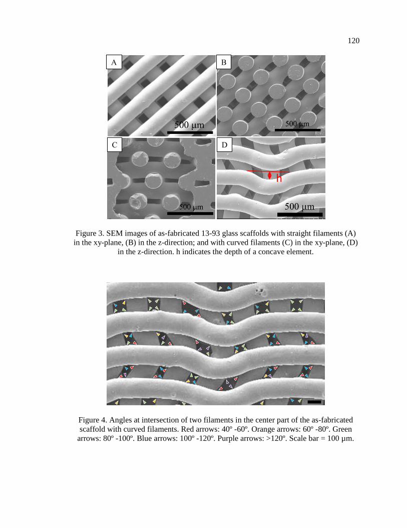
120
Figure 3. SEM images of as-fabricated 13-93 glass scaffolds with straight filaments (A)
in the xy-plane, (B) in the z-direction; and with curved filaments (C) in the xy-plane, (D)
in the z-direction. h indicates the depth of a concave element.
Figure 4. Angles at intersection of two filaments in the center part of the as-fabricated
scaffold with curved filaments. Red arrows: 40º -60º. Orange arrows: 60º -80º. Green
arrows: 80º -100º. Blue arrows: 100º -120º. Purple arrows: >120º. Scale bar = 100 µm.
A B
C D
h

121
Figure 5. SEM images of surface-modified 13-93 glass scaffold: (A) cross-section of
converted scaffold filament and (B) surface of converted glass filament.
Pre-treating scaffolds in a phosphate solution produced a thin (6 ± 1 µm)
conversion layer on the surfaces of the glass filaments (Figure 5A), and these converted
surfaces possessed both spherical nanoparticles and some needle-like nanoparticles
(Figure 5B). These observations are consistent with previous studies of the formation of
HA-like layers on the surfaces of 13-93 glass exposed to phosphate solutions [23, 24, 31,
35].
3.2. EVALUATION OF BONE REGENERATION IN RAT CALVARIAL
DEFECTS
Representative examples of the H&E stained sections from the four sets of
implants after six weeks in the rat calvarial defects are shown in Figure 6. New bone
formation was observed mainly at the edges of the defects (adjacent to the host bone) and
along the dura mater/bottom of the defects, where blood vessels could provide more
nutrients to the site. The amount of new bone growth, expressed as percentage of total
defect area and available pore space in the scaffold, was dependent on the microstructure
and surface-condition of the 13-93 glass scaffold, as shown in Table 2.
B A
Glass
Surface layer

122
Figure 6. H&E stained sections of implants composed of as-fabricated 13-93 glass
scaffold with straight (A1) or curved (B1) filaments, and surface-modified 13-93 glass
scaffold with straight (C1) or curved (D1) filaments, from rat calvarial defects after 6
weeks. HB: host bone; NB: new bone; G: glass.
A
B
C
D

123
Figure 7. H&E stained (A1-D1) and Toluidine blue stained (B2-D2) sections from the
center part of the implants: (A1, A2) as-fabricated scaffold with straight filaments; (B1,
B2) as-fabricated scaffold with curved filaments; (C1, C2) surface-modified scaffold with
straight filaments; (D1, D2) surface-modified scaffold with curved filaments;. * indicates
new bone. Yellow arrows indicate the accumulation of cells in the concave regions of the
curved filaments and at the intersection of two filaments. Red arrows are similar sites
corresponding to the yellow arrows. Scale bar = 100 µm.
A1
B1
C1
D1
A2
B2
C2
D2
*
*
*
* *
*
*
*
*
*
*
* *
*
*

124
Table 2. Percent new bone formed and total von Kossa positive area in rat calverial
defects implanted with the scaffolds at 6 weeks.
Group
New bone% Von Kossa positive %
Total area Available area Total area
1: straight 13 ± 3 25 ± 4 39 ± 4
2: curved 18 ± 4 30 ± 5 44 ± 4
3: pretreated straight 22 ± 6 40 ± 9 44 ± 5
4: pretreated curved 32 ± 8 56 ± 13 49 ± 6
H&E and Toluidine blue stained sections from the center parts of the implants for
as-fabricated and surface-modified scaffolds are shown in Figure 7. For the as-fabricated
scaffolds with straight filaments (Figure 7A1 and A2), accumulations of cells were found
at the intersections of the filaments, and new bone appears to be growing from the
intersections into the more open pore space. For the as-fabricated scaffold with curved
filaments (Figure 7B1 and B2), accumulations of cells and bone growth were found at
both filament intersections and in the concave regions of the filaments. For the surface-
modified scaffold with straight filaments (Figure 7C1 and C2), more bone formation was
observed than in the as-fabricated scaffolds, and the accumulations of cells and bone
maturation and remodeling were found at the filament intersections. For the surface-
modified scaffold with curved filaments (Figure 7D1 and D2), evidence for bone
maturation and remodeling was observed in the scaffold pores, whereas newly formed
bone was observed along the filament surfaces and in the concave regions of the curved
filaments.

125
Figure 8. Comparative new bone formation in rat calvarial defects implanted with 13-93
glass scaffolds at 6 weeks: as-fabricated scaffold with straight filament; as-fabricated
scaffolds with curved filaments; surface-modified scaffold with straight filaments;
surface-modified scaffolds with curved filaments. The new bone formation is shown as a
percent of available area in the scaffold. (Mean ± SD; n = 7, * significant difference
between groups; p < 0.05).
For as-fabricated 13-93 glass scaffolds, the percentages of new bone formation in
the total defect area was 13 ± 3% for straight-filament scaffolds (Group 1) and 18 ± 4%
for curved-filament scaffolds (Group 2). When normalized to the available pore space in
the scaffolds, the amounts of new bone formation were 25 ± 4% and 30 ± 5% for
scaffolds in Group 1 and Group 2, respectively. There was a statistically significant
improvement in bone regeneration in the scaffolds with curved filaments compared with
the scaffolds with straight filaments (n = 7, p < 0.05, Figure 8).
For the surface-modified 13-93 glass scaffolds, values for new bone regeneration
in the total defect areas were 22 ± 6% and 32 ± 8% for scaffolds with straight filaments

126
(Group 3) and curved filaments (Group 4), respectively. When normalized to the
available pore space in the scaffolds, the percentages of new bone growth were 40 ± 9%
and 56 ± 13% for Group 3 and Group 4, respectively. Again, for the surface-modified 13-
93 glass scaffolds, scaffolds with curved filaments showed statistically more new bone
formation than scaffolds with straight filaments (n = 7, p < 0.05, Figure 8).
For both the straight-filament and curved-filament designs, the pre-reacted
scaffolds were more effective in promoting bone regeneration than the as-fabricated
scaffolds (n = 7, p< 0.05, Figure 8).
3.3. EVALUATION OF MINERALIZATION OF 13-93 GLASS SCAFFOLDS
Representative examples of the Von Kossa stained sections of implants from the
four sets of scaffolds are shown in Figure 9. A combination of mineralized bone and HA
converted from the glass can be detected by von Kossa staining. The von Kossa positive
areas (dark stain) are summarized in Table 2. The scaffolds with curved filaments showed
significantly greater von Kossa positive areas than the scaffolds with straight filaments,
for both as-fabricated and surface-modified scaffolds (n = 7, p < 0.05, Figure 10). For
both the straight-filament and curved-filament designs, the pre-reacted scaffolds had
significantly more von Kossa positive areas than the as-fabricated scaffolds (n = 7, p<
0.05, Figure 10).

127
Figure 9. Von Kossa stained sections of implants composed of as-fabricated 13-93 glass
scaffold with straight (A) or curved (B) filaments or surface-modified 13-93 glass
scaffold with straight (C) or curved (D) filaments, from rat calvarial defect after 6 weeks.
HB: host bone; NB: new bone; G: glass.
A
B
C
D

128
Figure 10. Comparative von Kossa positive areas for implants of 13-93 glass scaffolds in
rat calvarial defects after 6 weeks: as-fabricated scaffolds with straight filaments; as-
fabricated scaffolds with curved filaments; surface-modified scaffolds with straight
filaments; surface-modified scaffolds with curved filaments. The von Kossa positive
areas are shown as a percent of available area in the scaffold. (Mean ± SD; n = 7, *
significant difference between groups; p < 0.05).
In order to evaluate the amount of von Kossa positive area that could be attributed
to the formation of HA by the in vivo conversion of glass, the percent new bone
determined from H&E staining (as a fraction of total available area) was subtracted from
the percent von Kossa positive area. The von Kossa positive area due to HA formation by
the in vivo conversion of the glass from Group 1 to Group 4 were 25 ± 5%, 25 ± 6%, 21 ±
3% and 19 ± 6%, respectively. There was no significant difference in the von Kossa
positive area due to glass conversion among the four groups (n = 7, p > 0.05).

129
Figure 11. Backscatter SEM images of implants composed of as-fabricated 13-93 glass
scaffolds with straight (A1) or curved (B1) filaments, or surface-modified 13-93 glass
scaffold with straight (C1) or curved (D1) filaments, from rat calvarial defects after 6
weeks; (A2-D2) higher magnification images of boxed areas in (A1-D1). NB: new bone;
G: glass.
A1 A2
B1 B2
C1
D1
C2
D2
Surface layer
Surface layer
Surface layer
Surface layer

130
Figure 11 shows backscatter SEM images of implants from the rat calvarial
defects. The contrast in the grayscale images is an indication of differences in the calcium
contents of the different areas including the glass scaffold, the converted surface layer,
and the new bone [24, 30, 34]. Ca-rich areas are light gray, the silica-rich layer that forms
on filaments in the early stage of glass conversion is dark gray, and lacunae and soft
tissue regions are almost black. The glass filaments show three cross-sectional regions
with different levels of grayscale: the inner-most region is unconverted glass, the middle
region is the silica-rich layer, and the outermost region is the HA-like surface layer on the
filament. For the as-fabricated scaffolds, the thickness of the HA-like surface layer in
Group 1 (17 ± 2 m) was similar to that in Group 2 (17 ± 1 m). For the surface-
modified scaffolds, the thicknesses of the surface layers in Group 3 and Group 4 were 8 ±
2 m and 7 ± 2 m, respectively, about one-half of the thicknesses of the layers that
formed in vivo on the as-fabricated scaffolds.
4. DISCUSSION
The reactions that occur at the surfaces of bioactive silicate glasses implanted in
osteo-defects have been described by Hench [36] and updated by Gerhardt et al. [37], and
are summarized in Table 3. Stages 1-3 involve the exchange of alkali and alkaline earth
ions from the glass with protonated water (H3O+) in the local environment to create a
silica-rich surface layer. An amorphous Ca-phosphate layer forms on the surface of the
silica-rich layer when Ca2+ ions released from the glass react with phosphate and

131
carbonate anions in the physiological environment, and this layer then crystallizes to
form carbonated hydroxyapatite (HCA) (Stages 4-5). Cells then attach, proliferate, and
differentiate on the HCA surface (Stages 6-9), to generate extracellular matrix, crystallize
inorganic hydroxyapatite, and form new bone (Stages 10-12). The progress of these
reactions is determined by the composition and architecture of the glass scaffolds.
Table 3. Sequence of interfacial reactions involved in forming a bond between bioactive
glass and bone [36, 37].
Reaction events Stages
Exchange of alkali ions with H3O+ ions from body fluids 1
Network dissolution and formation of silanol (SiOH) bonds 2
Silca-gel polymerization: SiOH + SiOH → Si-O-Si 3
Adsorption of amorphous Ca + PO4 + CO3 4
Crystallization of HCA layer 5
Biochemical adsorption of proteins (growth factors) on HCA layer 6
Macrophages remove debris from site allowing cells to occupy the space 7
Attachment of stem cells 8
Differentiation of stem cells to form osteoblasts 9
Generation of extracellular matrix 10
Crystallization of inorganic calcium phosphate 11
Proliferation and growth of bone 12

132
The in vivo experiments showed that the amount of bone regeneration after six
weeks in rat calvarial defects depended on both the geometry of the 13-93 glass scaffold
filaments, curved filaments were more effective than straight filaments, and the surface
condition of the filaments where HA-converted filaments were more effective than the
as-fabricated filaments (Figures 8 and 10). In addition, new bone formation appears to be
enhanced at filament-filament intersections and in the concave regions of the curved
filaments (Figure 7).
The influence of scaffold surface concavity on bone regeneration has been
investigated in previous studies [38-43]. For example, the in vitro mineralization of
calcium phosphate is enhanced in surface cavities (0.4 mm) compared to planar surfaces
[38], and cell proliferation was enhanced on scaffolds with greater surface curvature [39].
Stem cells showed better maturation, osteo-differentiation, and specific protein
production on a concave surface than a flat surface [40]. Both in vitro and in vivo studies
[21, 28, 44, 45] have demonstrated that bone tissue growth is enhanced by surface
curvature [28]. An in vivo test showed that concavities stimulated the formation of blood
vessels which play an important role in bone regeneration [41]. Bone formation by
intramembranous ossification was preferred on a concave surface [42], and concavity was
shown to be conducive to the accumulation of growth factors, such as bone
morphogenetic proteins (BMPs) [43]. Similar effects may contribute to the enhanced
bone regeneration associated with the scaffolds formed from curved filaments compared
to those with straight filaments, noted in the present study.
Further, the pore size and overall porosity of scaffolds are important parameters
for bone regeneration [46]. The pore size and porosity influence cell adhesion,

133
proliferation and distribution by affecting the access to cell recruitment, vascularization,
nutrients and oxygen. Interconnected porous structures with pore sizes at least 100 µm
have been recommended for scaffolds to regenerate bone due to cell size, migration
requirements, and transport, and pore sizes > 300 µm lead to enhancement of new bone
formation and vascularization [46]. An in vivo test of dental implants coated with
cancellous structured titanium showed that a slight increase in porosity (from 44% to
48%) could increase the rate of new bone growth [47]. In the present study, the pore
sizes of our scaffolds limited by the diameter of glass filament and robocasting technique
are larger than 100 µm. Moreover, the scaffold with curved filaments had slightly greater
overall porosity (45 ± 3%) and pore dimensions (150 ± 5 µm 70 ± 8 µm) than scaffolds
with straight filaments (porosity = 41 ± 2 %, pore dimensions = 117 ± 3 µm 75 ± 5
µm), and these differences might also contribute to the enhanced bone formation
associated with the former structures.
After 6-weeks implantation, an HA-like layer formed on the surfaces of the
filaments that constituted the structures of each scaffold, as observed by the SEM images
for both as-fabricated and surface-modified samples (Fig, 11). 13-93 glass is a bioactive
silicate glass that reacts in vivo to initially form a silica-rich layer (Stages 1-3), on which
an HA-like surface layer forms (Stages 4-5) [3, 15, 24, 48, 49]. For surface-modified
scaffolds, no silica-rich layer was observed after the pretreatment (Figure 4A) due to the
high solubility of silica at pH=12 [50], whereas a silica-rich layer was apparent (Figure
12C1-2 and D1-2) after implantation in vivo. The thickness of the HA layer that formed
in vivo on the as-fabricated scaffold was about twice that of the surface-modified
scaffold. The thickness of the HA layer in surface-modified scaffold did not change

134
much, from about 6 µm to 7-8 µm, after 6 weeks implantation in the rat calvarial defect.
The thin HA-like layer obtained by pretreatment in phosphate solution could reduce the
glass conversion rate in vivo [27], if that layer hinders the penetration of body fluids to
react with the unconverted glass, or if the pre-treatment alters the glass chemistry at the
glass-HA interface.
The surface-modified scaffolds promoted greater levels of new bone formation
compared to the as-fabricated scaffolds (Figure 8), consistent with a previous in vivo
study of 13-93 glass scaffolds [27]. From that study, three points were raised. First, the
HA layer on the surface of a glass scaffold obtained by pretreatment must interact with
cells, tissues and some growth factors to promote bone formation [13, 23, 36, 51].
Second, when the as-fabricated scaffold initially reacts with the body fluid to form the
silica-rich gel on the surface, this reaction could irreversibly denature proteins such as
BMP-2 [13, 36, 51, 52]. Third, initial ion-exchange reactions at the glass surfaces
increase the pH and osmolarity of the local physiological environment [48, 49, 53], and
this could adversely affect cell viability and subsequent cellular and tissue interactions
[54].
The in vivo results of the present work showed that the surface-modified scaffolds
with curved filaments had a better capacity to facilitate new bone formation than
scaffolds made with straight filaments, although differences in porosity and pore size
between the two sets of scaffolds may also contribute to the enhanced bone regeneration.
Pre-treating the scaffolds to produce a thin calcium phosphate layer on the glass surface
improves the capability of the scaffold to support new bone formation. However, there
are still some points that need to be investigated. For instance, the optimum fraction and

135
curvature of the concavities for bone regeneration are not known, nor is the optimum
thickness of the pre-treatment layer.
5. CONCLUSIONS
The geometry and surface condition of the filaments that constitute 13-93 glass
scaffolds affect the generation of new bone after six weeks in rat calvarial defects.
Scaffolds constructed from curved filaments exhibited enhanced bone regeneration
compared to scaffolds made with straight filaments. Pre-reacting the scaffolds to form
calcium phosphate surface layers also increased the capacity to improve new bone
formation.
ACKNOWLEDGMENT
Youqu Shen appreciates the financial support she received from the Missouri
S&T Center for Biomedical Research (CBR) and the Lasko Endowment in the Materials
Science and Engineering Department. We thank colleagues in the Missouri S&T
Materials Research Center and Richard Watters from the CBR Animal Research Facility
for technical assistance.

136
REFERENCES
[1] V. Campana, G. Milano, E. Pagano, M. Barba, C. Cicione, G. Salonna, W.
Lattanzi, and G. Logroscino, Bone substitutes in orthopaedic surgery: from basic
science to clinical practice. Journal of Materials Science: Materials in Medicine,
2014. 25(10): p. 2445-2461.
[2] F. Deschaseaux, L. Sensébé, and D. Heymann, Mechanisms of bone repair and
regeneration. Trends in Molecular Medicine, 2009. 15(9): p. 417-429.
[3] M.N. Rahaman, D.E. Day, B.S. Bal, Q. Fu, S.B. Jung, L.F. Bonewald, and A.P.
Tomsia, Bioactive glass in tissue engineering. Acta biomaterialia, 2011. 7(6): p.
2355-2373.
[4] A.A. El-Rashidy, J.A. Roether, L. Harhaus, U. Kneser, and A.R. Boccaccini,
Regenerating bone with bioactive glass scaffolds: A review of in vivo studies in
bone defect models. Acta Biomaterialia, 2017. 62: p. 1-28.
[5] L. Polo-Corrales, M. Latorre-Esteves, and J.E. Ramirez-Vick, Scaffold design for
bone regeneration. Journal of nanoscience and nanotechnology, 2014. 14(1): p.
15-56.
[6] M.N. Rahaman, W. Xiao, and W. Huang, bioactive glass implants for potential
application in structural bone repair. Biomedical Glasses, 2017. 3(1): p. 56-66.
[7] L. Bi, M.N. Rahaman, D.E. Day, Z. Brown, C. Samujh, X. Liu, A.
Mohammadkhah, V. Dusevich, J.D. Eick, and L.F. Bonewald, Effect of bioactive
borate glass microstructure on bone regeneration, angiogenesis, and
hydroxyapatite conversion in a rat calvarial defect model. Acta Biomaterialia,
2013. 9(8): p. 8015-8026.
[8] J. Samira, M. Saoudi, K. Abdelmajid, O. Hassane, R. Treq, E. Hafed, E.
Abdelfatteh, and K. Hassib, Accelerated bone ingrowth by local delivery of Zinc
from bioactive glass: oxidative stress status, mechanical property, and
microarchitectural characterization in an ovariectomized rat model. Libyan
Journal of Medicine, 2015. 10(1): p. 28572-28572.
[9] V. Aina, A. Perardi, L. Bergandi, G. Malavasi, L. Menabue, C. Morterra, and D.
Ghigo, Cytotoxicity of zinc-containing bioactive glasses in contact with human
osteoblasts. Chemico-Biological Interactions, 2007. 167(3): p. 207-218.

137
[10] Y. Lin, W. Xiao, B.S. Bal, and M.N. Rahaman, Effect of copper-doped silicate
13–93 bioactive glass scaffolds on the response of MC3T3-E1 cells in vitro and
on bone regeneration and angiogenesis in rat calvarial defects in vivo. Materials
Science & Engineering C, 2016. 67: p. 440-452.
[11] H. Wang, S. Zhao, J. Zhou, Y. Shen, W. Huang, C. Zhang, M.N. Rahaman, and
D. Wang, Evaluation of borate bioactive glass scaffolds as a controlled delivery
system for copper ions in stimulating osteogenesis and angiogenesis in bone
healing. Journal of Materials Chemistry B, 2014. 2(48): p. 8547-8557.
[12] C. Zhang, J. Zhang, S. Zhao, M. Zhu, Y. Zhu, Y. Huang, and C. Tao, Three-
dimensional printing of strontium-containing mesoporous bioactive glass
scaffolds for bone regeneration. Acta Biomaterialia, 2014. 10(5): p. 2269-2281.
[13] L.L. Hench, The story of Bioglass®. Journal of Materials Science: Materials in
Medicine, 2006. 17(11): p. 967-978.
[14] L.L. Hench, R.J. Splinter, W. Allen, and T. Greenlee, Bonding mechanisms at the
interface of ceramic prosthetic materials. Journal of biomedical materials
research, 1971. 5(6): p. 117-141.
[15] M. Brink, Bioactive glasses with a large working range. 1997: Åbo Akademi
University, Department of Chemical Engineering.
[16] M. Brink, The influence of alkali and alkaline earths on the working range for
bioactive glasses. Journal of Biomedical Materials Research: An Official Journal
of The Society for Biomaterials and The Japanese Society for Biomaterials, 1997.
36(1): p. 109-117.
[17] M. Brink, T. Turunen, R.P. Happonen, and A. Yli‐Urpo, Compositional
dependence of bioactivity of glasses in the system Na2O‐K2O‐MgO‐CaO‐B2O3‐P2O5‐SiO2. Journal of Biomedical Materials Research: An Official Journal
of The Society for Biomaterials and The Japanese Society for Biomaterials, 1997.
37(1): p. 114-121.
[18] S. Giannitelli, D. Accoto, M. Trombetta, and A. Rainer, Current trends in the
design of scaffolds for computer-aided tissue engineering. Acta biomaterialia,
2014. 10(2): p. 580-594.
[19] S.-I. Roohani-Esfahani, P. Newman, and H. Zreiqat, Design and Fabrication of
3D printed Scaffolds with a Mechanical Strength Comparable to Cortical Bone to
Repair Large Bone Defects. Scientific Reports, 2016. 6(1): p. 19468.

138
[20] J.M. Sobral, S.G. Caridade, R.A. Sousa, J.F. Mano, and R.L. Reis, Three-
dimensional plotted scaffolds with controlled pore size gradients: Effect of
scaffold geometry on mechanical performance and cell seeding efficiency. Acta
Biomaterialia, 2011. 7(3): p. 1009-1018.
[21] M. Paris, A. Götz, I. Hettrich, C.M. Bidan, J.W.C. Dunlop, H. Razi, I. Zizak,
D.W. Hutmacher, P. Fratzl, G.N. Duda, W. Wagermaier, and A. Cipitria, Scaffold
curvature-mediated novel biomineralization process originates a continuous soft
tissue-to-bone interface. Acta Biomaterialia, 2017. 60: p. 64-80.
[22] W. Xiao, M.A. Zaeem, B.S. Bal, and M.N. Rahaman, Creation of bioactive glass
(13–93) scaffolds for structural bone repair using a combined finite element
modeling and rapid prototyping approach. Materials Science & Engineering C,
2016. 68: p. 651-662.
[23] Q. Fu, M.N. Rahaman, B. Sonny Bal, R.F. Brown, and D.E. Day, Mechanical and
in vitro performance of 13–93 bioactive glass scaffolds prepared by a polymer
foam replication technique. Acta Biomaterialia, 2008. 4(6): p. 1854-1864.
[24] X. Liu, M.N. Rahaman, and Q. Fu, Bone regeneration in strong porous bioactive
glass (13-93) scaffolds with an oriented microstructure implanted in rat calvarial
defects. Acta Biomaterialia, 2013. 9(1): p. 4889-4898.
[25] X. Liu, M.N. Rahaman, Q. Fu, and A.P. Tomsia, Porous and strong bioactive
glass (13-93) scaffolds prepared by unidirectional freezing of camphene-based
suspensions. Acta biomaterialia, 2012. 8(1): p. 415-423.
[26] X. Liu, M.N. Rahaman, G.E. Hilmas, and B.S. Bal, Mechanical properties of
bioactive glass (13-93) scaffolds fabricated by robotic deposition for structural
bone repair. Acta Biomaterialia, 2013. 9(6): p. 7025-7034.
[27] X. Liu, M.N. Rahaman, Y. Liu, B.S. Bal, and L.F. Bonewald, Enhanced bone
regeneration in rat calvarial defects implanted with surface-modified and BMP-
loaded bioactive glass (13-93) scaffolds. Acta biomaterialia, 2013. 9(7): p. 7506-
7517.
[28] M. Rumpler, A. Woesz, J.W.C. Dunlop, T.v.D. Joost, and P. Fratzl, The effect of
geometry on three-dimensional tissue growth. Journal of The Royal Society
Interface, 2008. 5(27): p. 1173-1180.

139
[29] M.N. Rahaman, W. Xiao, Y. Liu, and B. Sonny Bal. Osteoconductive and
Osteoinductive Implants Composed of Hollow Hydroxyapatite Microspheres. in
Advances in Bioceramics and Porous Ceramics VII: A Collection of Papers
Presented at the 38th International Conference on Advanced Ceramics and
Composites January 27-31, 2014 Daytona Beach, Florida. 2015. John Wiley &
Sons, Inc.
[30] Y. Shen, M. Rahaman, Y. Liu, and Y.-W. Huang, Evaluation of open hollow
CDHA microspheres on bone regeneration in rat calvarial defects.
[31] Y. Lin, W. Xiao, X. Liu, B.S. Bal, L.F. Bonewald, and M.N. Rahaman, Long-term
bone regeneration, mineralization and angiogenesis in rat calvarial defects
implanted with strong porous bioactive glass (13–93) scaffolds. Journal of Non-
Crystalline Solids, 2016. 432: p. 120-129.
[32] J.Q. Feng, J. Zhang, S.L. Dallas, Y. Lu, S. Chen, X. Tan, M. Owen, S.E. Harris,
and M. Macdougall, Dentin matrix protein 1, a target molecule for Cbfa1 in bone,
is a unique bone marker gene. Journal of Bone and Mineral Research, 2002.
17(10): p. 1822-1831.
[33] G. Sridharan and A.A. Shankar, Toluidine blue: A review of its chemistry and
clinical utility. Journal of Oral and Maxillofacial Pathology, 2012. 16(2): p. 251-
255.
[34] L. Bonewald, S. Harris, J. Rosser, M. Dallas, S. Dallas, N. Camacho, B. Boyan,
and A. Boskey, von Kossa staining alone is not sufficient to confirm that
mineralization in vitro represents bone formation. Calcified tissue international,
2003. 72(5): p. 537-547.
[35] X. Liu, M.N. Rahaman, Y. Liu, B.S. Bal, and L.F. Bonewald, Enhanced bone
regeneration in rat calvarial defects implanted with surface-modified and BMP-
loaded bioactive glass (13-93) scaffolds. Acta Biomaterialia, 2013. 9(7): p. 7506-
17.
[36] L.L. Hench, Bioceramics. Journal of the American Ceramic Society, 1998. 81(7):
p. 1705-1727.
[37] L.-C. Gerhardt and A.R. Boccaccini, Bioactive glass and glass-ceramic scaffolds
for bone tissue engineering. Materials, 2010. 3(7): p. 3867-3910.
[38] M. Bianchi, E.R.U. Edreira, J.G. Wolke, Z.T. Birgani, P. Habibovic, J.A. Jansen,
A. Tampieri, M. Marcacci, S.C. Leeuwenburgh, and J.J. Van Den Beucken,
Substrate geometry directs the in vitro mineralization of calcium phosphate
ceramics. Acta biomaterialia, 2014. 10(2): p. 661-669.

140
[39] K.C.R. Kolan, A. Thomas, M.C. Leu, and G. Hilmas, In vitro assessment of laser
sintered bioactive glass scaffolds with different pore geometries. Rapid
Prototyping Journal, 2015. 21(2): p. 152-158.
[40] A. Graziano, R. d'Aquino, M.G. Cusella-De Angelis, G. Laino, A. Piattelli, M.
Pacifici, A. de Rosa, and G. Papaccio, Concave Pit-Containing Scaffold Surfaces
Improve Stem Cell-Derived Osteoblast Performance and Lead to Significant Bone
Tissue Formation. PLoS ONE, 2007. 2(6): p. e496.
[41] A. Scarano, V. Perrotti, L. Artese, M. Degidi, D. Degidi, A. Piattelli, and G. Iezzi,
Blood vessels are concentrated within the implant surface concavities: a
histologic study in rabbit tibia. Odontology, 2014. 102(2): p. 259-266.
[42] M.J. Coathup, K.A. Hing, S. Samizadeh, O. Chan, Y.S. Fang, C. Campion, T.
Buckland, and G.W. Blunn, Effect of increased strut porosity of calcium
phosphate bone graft substitute biomaterials on osteoinduction. Journal of
Biomedical Materials Research Part A, 2012. 100(6): p. 1550-1555.
[43] U.R. Ripamonti, Functionalized surface geometries induce:" Bone: formation by
autoinduction". Frontiers in physiology, 2017. 8: p. 1084.
[44] C.M. Bidan, K.P. Kommareddy, M. Rumpler, P. Kollmannsberger, Y.J.M.
Bréchet, P. Fratzl, and J.W.C. Dunlop, How linear tension converts to curvature:
Geometric control of bone tissue growth. PLoS ONE, 2012. 7(5): p. e36336.
[45] M.A. Alias and P.R. Buenzli, Modeling the Effect of Curvature on the Collective
Behavior of Cells Growing New Tissue. Biophysical Journal, 2017. 112(1): p.
193-204.
[46] V. Karageorgiou and D. Kaplan, Porosity of 3D biomaterial scaffolds and
osteogenesis. Biomaterials, 2005. 26(27): p. 5474-5491.
[47] B.J. Story, W.R. Wagner, D.M. Gaisser, S.D. Cook, and A.M. Rust-Dawicki, In
vivo performance of a modified CSTi dental implant coating. International Journal
of Oral & Maxillofacial Implants, 1998. 13(6).
[48] W. Huang, D.E. Day, K. Kittiratanapiboon, and M.N. Rahaman, Kinetics and
mechanisms of the conversion of silicate (45S5), borate, and borosilicate glasses
to hydroxyapatite in dilute phosphate solutions. Journal of Materials Science:
Materials in Medicine, 2006. 17(7): p. 583-596.
[49] A. Yao, D. Wang, W. Huang, Q. Fu, M.N. Rahaman, and D.E. Day, In vitro
bioactive characteristics of borate-based glasses with controllable degradation
behavior. Journal of the American Ceramic Society, 2007. 90(1): p. 303-306.
141
[50] B.C. Bunker, Molecular mechanisms for corrosion of silica and silicate glasses.
Journal of Non-Crystalline Solids, 1994. 179: p. 300-308.
[51] H. Fu, M.N. Rahaman, D.E. Day, and R.F. Brown, Hollow hydroxyapatite
microspheres as a device for controlled delivery of proteins. Journal of Materials
Science: Materials in Medicine, 2011. 22(3): p. 579-591.
[52] R.A. Messing, Insoluble papain prepared by adsorption on porous glass.
Enzymologia, 1970. 38(1): p. 39-42.
[53] Q. Fu, M.N. Rahaman, H. Fu, and X. Liu, Silicate, borosilicate, and borate
bioactive glass scaffolds with controllable degradation rate for bone tissue
engineering applications. I. Preparation and in vitro degradation. Journal of
Biomedical Materials Research Part A, 2010. 95A(1): p. 164-171.
[54] J.P. Mather and P.E. Roberts, Introduction to cell and tissue culture: theory and
technique. 1998: Springer Science & Business Media.

142
SECTION
3. CONCLUSION
3.1. SUMMARY
1) Open CDHA microspheres, produced by sectioning closed microspheres, promote
greater new bone formation after six weeks and twelve weeks in rat calvarial defects
then do the closed microspheres.
2) Open CDHA microspheres with smaller radii (53-75 µm) promote greater new bone
formation than open HA microspheres with larger radii (106-125 µm).
3) Open and closed CDHA microspheres loaded with the same amount of BMP-2 (0.25
μg per defect) promoted similar levels of new bone formation after six 6-weeks
implantation in rat calvarial defects.
4) Hollow BCP microspheres were produced by the heat-treatment of CDHA
microspheres obtained by glass conversion technique. The composition and
microstructure of the microspheres was affected by the concentration and pH value
of the phosphate solution used in the glass conversion process.
5) Two sets of CDHA microspheres (Ca/P ≈ 1.55 and 1.59) and the corresponding BCP
microspheres (-TCP/HA =70/30 and 44/56) were selected for further in vitro tests.
The BCP microspheres with 70 wt% -TCP showed faster reaction rates in acetic
acid (pH=5) and simulated body fluid.
6) Two sets of CDHA microspheres (Ca/P ≈ 1.55 and 1.59) and the corresponding
BCP microspheres (-TCP/HA =70/30 and 44/56) were implanted in both calvarial

143
and subcutaneous sites in rats. The BCP microspheres with 70 wt% -TCP showed
faster in vivo degradation rates, and the best ability to promote new bone formation
in the calvarial defects, and to promote blood vessel formation in the subcutaneous
defects, compared to the other groups of microspheres.
7) The ability to tailor the composition, nano-structure, and meso-structure of these
microspheres by controlling the processing conditions to convert the soluble Ca-
containing borate glasses in phosphate solutions means that materials can be designed
for specific biomedical applications that utilize the macro-porosity of the hollow
microspheres, the nano-porosity of the shell walls, and the enhanced bio-activity of
the BCP phases.
8) The geometry and surface condition of the filaments that constitute 13-93 glass
scaffolds affect the generation of new bone after six weeks in rat calvarial defects.
Scaffolds constructed from curved filaments exhibited enhanced new bone formation
compared to scaffolds made with straight filaments. Pre-reacting the scaffolds to
form calcium phosphate surface layers also increased the capacity to promote new
bone formation.
3.2. RECOMMENDATIONS FOR FUTURE WORK
3.2.1. The Effect of Open CDHA Microspheres on Bone Regeneration. Open
CDHA microspheres can enhance bone formation compared to closed CDHA
microspheres, and smaller open microspheres showed enhanced new bone formation
compared with larger open microspheres. The mechanism for this enhancement is not
known and needs to be studied. The optimum open sphere radius has not been

144
determined; open spheres with radii smaller than 53 microns and larger than 125 microns
should be studied to determine if there is a reproducible trend in microsphere radius on
bone formation. The enhanced bone formation associated with BCP particles compared
to CDHA particles indicates that open BCP microspheres with large -TCP contents
could be most effective for enhancing new bone formation.
3.2.2. Determine the Optimal Size of Open CDHA Microspheres and Dosage
of BMP-2 for Bone Regeneration. We do not know how BMP-2 is incorporated into
the closed or open CDHA microspheres, whether it is only absorbed on the surfaces of
the particles or in the nanoporosity of the particles. The optimal BMP-2 dosage has not
been determined, nor have the release rates (pharmakinetics) from the particles. This
information must be acquired before treatments with BMP-2-loaded CDHA microspheres
can be considered beyond these preliminary results.
3.2.3. Evaluation of BCP Microspheres in Bone Regeneration. The
compositions and microstructures of BCP particles are affected by the conditions of glass
conversion and heat-treatment. The optimal design of BCP microspheres can be
determined with more in vitro and in vivo experiments. The osteoinductivity of BCPs
have been reported in other studies, but our BCP microspheres in current study did not
show osteoinductivity in rat subcutaneous defects at up to 12 weeks. The osteoinductivity
of BCP microspheres with modified compositions needs future investigation. The
potential of BCP microspheres for protein delivery can be evaluated by loading some
proteins, such as BSA, BMP-2, and then measuring release rates in standard solutions.
3.2.4. 13-93 Glass Scaffolds with Curved Filaments for Bone Regeneration.
The in vivo results of the present work showed that the surface-modified scaffolds with

145
curved filaments had a better capacity to facilitate new bone formation than scaffolds
made with straight filaments. The optimum fraction and curvature of the concavities for
bone regeneration is not known, nor is the optimum thickness of the pre-treatment layer.
The scaffolds with larger fraction and curvature of curved filaments need to be fabricated
for further in vivo tests. The effect of the fraction and curvature on the mechanical
properties of the scaffolds also deserve further investigation by evaluating the
compressive strengths and tensile strengths.

146
APPENDIX A.
BONE REGENERATION FACILATED BY OPEN CDHA MICROSPEHRES
LOADED WITH LOW DOSES OF BMP-2

147
Figure A.1. H&E and von Kossa stained sections of implants composed of closed (A1,
B1) and open (A2, B2) CDHA microspheres without BMP-2 after 6 weeks in rat calvarial
defects; (C, D) higher-magnification images of boxed area in (A1, A2). HB: host bone;
NB: new bone. Blue arrow: new bone growth in micro-concavity.

148
Figure A.2. H&E stained and von Kossa sections of implants composed of closed and
open hollow CDHA microspheres with BMP-2 after 6 weeks in rat calvarial defects:
closed HA microspheres with 1 μg BMP-2 (A1, B1); open CDHA microspheres with
0.25 μg BMP-2 (A2, B2); closed CDHA microspheres with 0.25 μg BMP-2 (A3, B3).
HB: host bone; NB: new bone.

149
Table A.1. Comparative new bone formation and von Kossa positive area in all implants
after 6 weeks in rat calvarial defects; the amount of new bone is expressed as a percent of
the total defect area (mean ± SD).
Hollow CDHA microspheres New bone (%) Positive area (%)
Closed 6 ± 2 30 ± 3
Open 12 ± 3 35 ± 3
Closed + 1 μg BMP-2 40 ± 6 69 ± 5
Closed + 0.25 μg BMP-2 26 ± 9 55 ± 8
Open + 0.25 μg BMP-2 24 ± 8 49 ± 7
Figure A.3. Comparative new bone formation in all implants after 6 weeks in rat calvarial
defects. (Mean ± SD; n = 5~10, * significant difference between groups; p < 0.05).
Closed CDHA microspheres denoted as “C”, open HA microspheres denoted as “O”, and
closed CDHA microspheres loaded with 1 µg BMP-2/defect are control groups. All
BMP2 concentration are µg/defect.
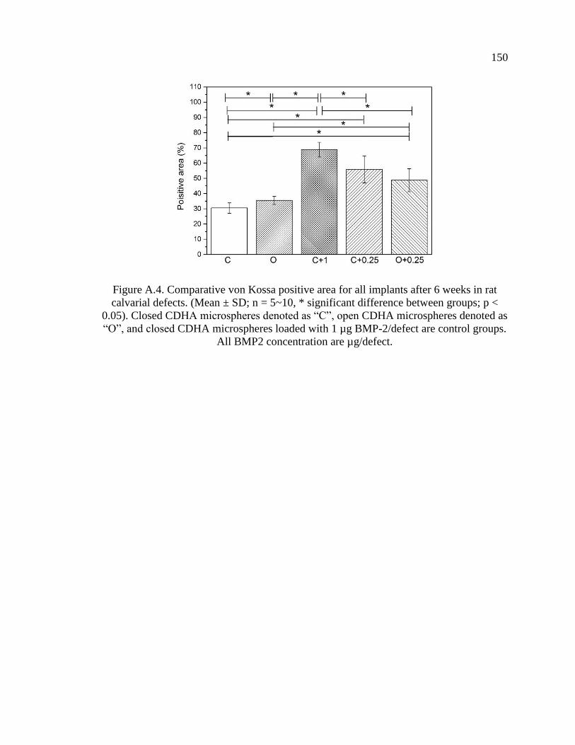
150
Figure A.4. Comparative von Kossa positive area for all implants after 6 weeks in rat
calvarial defects. (Mean ± SD; n = 5~10, * significant difference between groups; p <
0.05). Closed CDHA microspheres denoted as “C”, open CDHA microspheres denoted as
“O”, and closed CDHA microspheres loaded with 1 µg BMP-2/defect are control groups.
All BMP2 concentration are µg/defect.

APPENDIX B.
HOLLOW BIPHASIC CALCIUM PHOSPHATE MICROSPHERES FROM
GLASS DISSOLUTION AND REPRECIPITATION

152
Table B.1. The particle sizes in the external surface and the diameter ratios of hollow
core (d) to the microsphere size (D) of the microspheres produced in different conditions.
Microspheres
d/D Particle size (nm)
pH K2HPO4 solution (M) Heat-treatment
7 0.25 - 0.374 ± 0.011 133 ± 13
7 0.25 800°C/5h 0.353 ± 0.013 530 ± 90
9 0.25 - 0.370 ± 0.005 114 ± 10
9 0.25 800°C/5h 0.351 ± 0.017 570 ± 113
12 0.25 - 0.371 ± 0.006 90 ± 13
12 0.25 800°C/5h 0.363 ± 0.011 770 ± 294
7 0.1 - 0.543 ± 0.007 113 ± 16
7 0.1 800°C/5h 0.536 ± 0.011 365 ±130
9 0.1 - 0.546 ± 0.009 86 ± 10
9 0.1 800°C/5h 0.532 ± 0.012 576 ± 244
12 0.1 - 0.534 ± 0.013 84 ± 22
12 0.1 800°C/5h 0.518 ± 0.016 748 ± 253

153
Figure B.1. XRD patterns of the as-prepared (A) and heat-treated (B) microspheres
produced in 0.1 M K2HPO4 solution at various pH values.
A B

154
Figure B.2. Percentage of calcium (A) and phosphate (B) ions released from the
microspheres in KAc solution. (C) The Ca/P ion ratios released to the KAc solutions a
function of immersion time.
A B
C

155
Figure B.3. Changes of the Ca/P ion ratios released to the KAc solutions during
immersion time.
Figure B.4. Changes of pH value of the SBF solution after adding the microspheres
during two-weeks immersion at 37°C.

156
Figure B.5. SEM images of the external surfaces of the BCP microspheres: (A)
BCP/pH=7 and (B) BCP/pH=12 after two-weeks of immersion of SBF solution at 37°C.
Figure B.6. FTIR (A) and Raman (B) spectra of the microspheres before and after
immersion in SBF solution for 14 days. CDHA/pH=7: (a) before and (b) after;
BCP/pH=7: (c) before and (d) after; CDHA/pH=12: (e) before and (f) after; BCP/pH=12:
(g) before and (h) after.
A B
A B
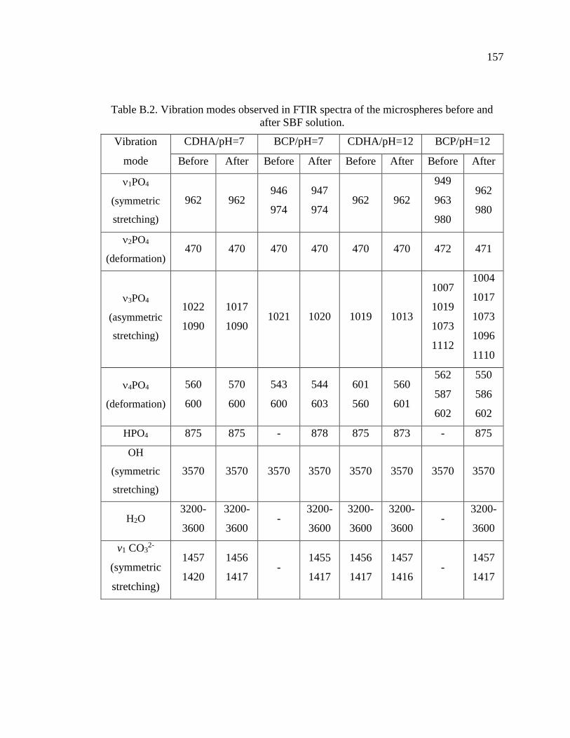
157
Table B.2. Vibration modes observed in FTIR spectra of the microspheres before and
after SBF solution.
Vibration
mode
CDHA/pH=7 BCP/pH=7 CDHA/pH=12 BCP/pH=12
Before After Before After Before After Before After
1PO4
(symmetric
stretching)
962 962 946
974
947
974 962 962
949
963
980
962
980
2PO4
(deformation) 470 470 470 470 470 470 472 471
3PO4
(asymmetric
stretching)
1022
1090
1017
1090 1021 1020 1019 1013
1007
1019
1073
1112
1004
1017
1073
1096
1110
4PO4
(deformation)
560
600
570
600
543
600
544
603
601
560
560
601
562
587
602
550
586
602
HPO4 875 875 - 878 875 873 - 875
OH
(symmetric
stretching)
3570 3570 3570 3570 3570 3570 3570 3570
H2O 3200-
3600
3200-
3600 -
3200-
3600
3200-
3600
3200-
3600 -
3200-
3600
v1 CO32-
(symmetric
stretching)
1457
1420
1456
1417 -
1455
1417
1456
1417
1457
1416 -
1457
1417

158
Figure B.7. XRD patterns of the CDHA and BCP microspheres produced at pH=7 (A)
and pH=12 (B) before and after immersion in SBF solution for 14 days.
A B

APPENDIX C.
13-93 GLASS SCAFFOLDS WITH CURVED FILAMENTS

160
Figure C.1. Toluidine blue stained sections of implants composed of as-fabricated 13-93
glass scaffolds with straight (A) or curved (B) filaments or surface-modified 13-93 glass
scaffolds with straight (C) or curved (D) filaments, from rat calvarial defect after 6
weeks.
A
B
C
D

161
Table C.1. Thickness of silica-rich layers measured from SEM images of implanted
scaffolds (20 measurements).
Group Thickness of silica-rich layer
1 16 ± 4
2 19 ± 6
3 20 ± 7
4 18 ± 5
Table C.2. Ca/P atomic ratios in regions of the converted layer, the Si-rich layer, and
unconverted glass from Von Kossa stained samples, assuming Ca2+ is replaced by 2Ag+.
Group Converted layer Si-rich layer Unconverted glass
1 1.59 ± 0.10 3.04 ± 0.35 5.68 ± 1.76
2 1.63 ± 0.20 3.16 ± 0.41 5.79 ± 0.71
3 1.55 ± 0.18 2.63 ± 0.31 5.48 ± 1.64
4 1.56 ± 0.09 2.75 ± 0.36 5.65 ± 1.12

162
BIBLIOGRAPHY
[1] V. Campana, G. Milano, E. Pagano, M. Barba, C. Cicione, G. Salonna, W.
Lattanzi, and G. Logroscino, Bone substitutes in orthopaedic surgery: from basic
science to clinical practice. Journal of Materials Science: Materials in Medicine,
2014. 25(10): p. 2445-2461.
[2] F. Deschaseaux, L. Sensébé, and D. Heymann, Mechanisms of bone repair and
regeneration. Trends in Molecular Medicine, 2009. 15(9): p. 417-429.
[3] F. Loi, L.A. Córdova, J. Pajarinen, T.-h. Lin, Z. Yao, and S.B. Goodman,
Inflammation, fracture and bone repair. Bone, 2015. 86: p. 119-130.
[4] I.H. Kalfas, Principles of bone healing. Neurosurg Focus, 2001. 10(4): p. E1.
[5] P. Pivonka and C.R. Dunstan, Role of mathematical modeling in bone fracture
healing. BoneKEy reports, 2012. 1: p. 221.
[6] A. Scarano, M. Degidi, G. Iezzi, G. Pecora, M. Piattelli, G. Orsini, S. Caputi, V.
Perrotti, C. Mangano, and A. Piattelli, Maxillary sinus augmentation with
different biomaterials: a comparative histologic and histomorphometric study in
man. Implant dentistry, 2006. 15(2): p. 197-207.
[7] L. Trombelli, Which reconstructive procedures are effective for treating the
periodontal intraosseous defect? Periodontology 2000, 2005. 37(1): p. 88-105.
[8] R.T. Kao, G. Conte, D. Nishimine, and S. Dault, Tissue engineering for
periodontal regeneration. Journal of the California Dental Association, 2005.
33(3): p. 205-215.
[9] N. Pandit, R. Malik, and D. Philips, Tissue engineering: a new vista in
periodontal regeneration. Journal of Indian Society of Periodontology, 2011.
15(4): p. 328.
[10] C. Dahlin and A. Johansson, Iliac Crest Autogenous Bone Graft versus Alloplastic
Graft and Guided Bone Regeneration in the Reconstruction of Atrophic Maxillae:
A 5‐Year Retrospective Study on Cost‐Effectiveness and Clinical Outcome.
Clinical implant dentistry and related research, 2011. 13(4): p. 305-310.
[11] P.V. Giannoudis, H. Dinopoulos, and E. Tsiridis, Bone substitutes: an update.
Injury, 2005. 36(3): p. S20-S27.

163
[12] J.A. McAuliffe, Bone graft substitutes. Journal of Hand Therapy, 2003. 16(2): p.
180-187.
[13] O. Reikerås, H. Shegarfi, C. Naper, F.P. Reinholt, and B. Rolstad, Impact of MHC
mismatch and freezing on bone graft incorporation: an experimental study in rats.
Journal of Orthopaedic Research, 2008. 26(7): p. 925-931.
[14] W. Wang and K.W.K. Yeung, Bone grafts and biomaterials substitutes for bone
defect repair: A review. Bioactive Materials, 2017. 2(4): p. 224-247.
[15] L.L. Hench and L.L. Hench, Bioceramics: From Concept to Clinic. Journal of the
American Ceramic Society, 1991. 74(7): p. 1487-1510.
[16] M.N. Richard, Bioactive behavior of a borate glass. Masters Theses, Missouri
University of Science and Technology, 2000.
[17] K.P. Fears, Formation of hollow hydroxyapatite microspheres. Masters Theses,
Missouri University of Science and Technology, 2001.
[18] X. Han and D.E. Day, Reaction of sodium calcium borate glasses to form
hydroxyapatite. Journal of Materials Science: Materials in Medicine, 2007. 18(9):
p. 1837-1847.
[19] Y. Yu, Z. Bacsik, M. Edén, u. Stockholms, f. Naturvetenskapliga, and m.
Institutionen för material- och, Contrasting in vitro apatite growth from bioactive
glass surfaces with that of spontaneous precipitation. Materials, 2018. 11(9): p.
1690.
[20] H. Fu, M.N. Rahaman, and D.E. Day, Effect of process variables on the
microstructure of hollow hydroxyapatite microspheres prepared by a glass
conversion method. Journal of the American Ceramic Society, 2010. 93(10): p.
3116-3123.
[21] L.C. Chow, Solubility of calcium phosphates. Monographs in oral science, 2001.
18: p. 94-111.
[22] S.V. Dorozhkin, Calcium orthophosphates (CaPO4): occurrence and properties.
Progress in Biomaterials, 2016. 5(1): p. 9-70.
[23] Y. Liu, X. Sheng, Y. Dong, and Y. Ma, Removal of high-concentration phosphate
by calcite: Effect of sulfate and pH. Desalination, 2012. 289: p. 66-71.
[24] N.N. Vanderspiegel, Reaction of potassium calcium borate glasses to form apatite
and dicalcium phosphate dihydrate. Masters Theses, Missouri University of
Science and Technology 2004.
164
[25] F. Bakan, A Systematic Study of the Effect of pH on the Initialization of Ca-
deficient Hydroxyapatite to β-TCP Nanoparticles. Materials (Basel, Switzerland),
2019. 12(3): p. 354.
[26] K. Salma, L. Berzina-Cimdina, and N. Borodajenko, Calcium phosphate
bioceramics prepared from wet chemically precipitated powders. Processing and
Application of Ceramics, 2010. 4(1): p. 45-51.
[27] Y. Gu, W. Xiao, L. Lu, W. Huang, M.N. Rahaman, and D. Wang, Kinetics and
mechanisms of converting bioactive borate glasses to hydroxyapatite in aqueous
phosphate solution. Journal of Materials Science, 2011. 46(1): p. 47-54.
[28] G.H. Nancollas and J. Zhang, Formation and dissolution mechanisms of calcium
phosphates in aqueous systems, in Hydroxyapatite and related materials, P.W.
Brown and B. Constantz, Editors. 1994, CPC Press, Inc.: United State of
America. p. 73-81.
[29] W. Huang, M.N. Rahaman, D.E. Day, and Y. Li, Mechanisms for converting
bioactive silicate, borate, and borosilicate glasses to hydroxyapatite in dilute
phosphate solution. Physics and Chemistry of Glasses-European Journal of Glass
Science and Technology Part B, 2006. 47(6): p. 647-658.
[30] A.-H. Yao, J. Lin, X. Duan, and W.-H. Huang, Formation mechanism of
multilayered structure on surface of bioactive borosilicate glass. Chinese Journal
of Inorganic Chemistry, 2008. 24(7): p. 1132-1136.
[31] S.B. Jung and D.E. Day, Conversion kinetics of silicate, borosilicate, and borate
bioactive glasses to hydroxyapatite. Physics and Chemistry of Glasses-European
Journal of Glass Science and Technology Part B, 2009. 50(2): p. 85-88.
[32] D. Zhao, W. Huang, M.N. Rahaman, D.E. Day, and D. Wang, Mechanism for
converting Al 2O 3-containing borate glass to hydroxyapatite in aqueous
phosphate solution. Acta Biomaterialia, 2009. 5(4): p. 1265-1273.
[33] A. Khawam and D.R. Flanagan, Solid-state kinetic models: Basics and
mathematical fundamentals. Journal of Physical Chemistry B, 2006. 110(35): p.
17315-17328.
[34] W. Huang, D.E. Day, and M.N. Rahaman, Conversion of tetranary borate glasses
to phosphate compounds in aqueous phosphate solution. Journal of the American
Ceramic Society, 2008. 91(6): p. 1898-1904.
[35] S. Kuşlu, F.Ç. Dişli, and S. Çolak, Leaching kinetics of ulexite in borax
pentahydrate solutions saturated with carbon dioxide. Journal of Industrial and
Engineering Chemistry, 2010. 16(5): p. 673-678.

165
[36] H. Temur, A. Yartaş, M. Çopur, and M. Muhtar Kocakerim, The kinetics of
dissolution of colemanite in H3PO4 solutions. Industrial and Engineering
Chemistry Research, 2000. 39(11): p. 4114-4119.
[37] J.L. George, Dissolution of borate glasses and precipitation of phosphate
compounds. 2015, Missouri University of Science and Technology.
[38] W. Xiao, B. Sonny Bal, and M.N. Rahaman, Preparation of resorbable
carbonate-substituted hollow hydroxyapatite microspheres and their evaluation in
osseous defects in vivo. Materials Science & Engineering C, 2016. 60: p. 324-332.
[39] A.M. Abdelghany, H.A. ElBatal, and F.M. EzzElDin, Bone bonding ability
behavior of some ternary borate glasses by immersion in sodium phosphate
solution. Ceramics International, 2012. 38(2): p. 1105-1113.
[40] K.L. Goetschius, The effect of composition on the viscosity, crystallization and
dissolution of simple borate glasses and compositional design of borate based
bioactive glasses. 2014, Missouri University of Science and Technology.
[41] A. Yao, D. Wang, W. Huang, Q. Fu, M.N. Rahaman, and D.E. Day, In vitro
bioactive characteristics of borate‐based glasses with controllable degradation
behavior. Journal of the American Ceramic Society, 2007. 90(1): p. 303-306.
[42] A.K. Yadav and P. Singh, A review of the structures of oxide glasses by Raman
spectroscopy. RSC Advances, 2015. 5(83): p. 67583-6769.
[43] D. Maniua, T. Iliescu, I. Ardelean, S. Cinta-Pinzaru, N. Tarcea, and W. Kiefer,
Raman study on B2O3-CaO glasses. Journal of Molecular Structure, 2003. 651-
653: p. 485-488.
[44] G.S. Sandhu, Synthesis and characterization of microspheres for controlled
release. Masters theses, Missouri University of Science and Technology, 2010.
[45] Q. Wang, W. Huang, D. Wang, B.W. Darvell, D.E. Day, and M.N. Rahaman,
Preparation of hollow hydroxyapatite microspheres. Journal of Materials Science:
Materials in Medicine, 2006. 17(7): p. 641-646.
[46] Manupriya, K.S. Thind, D. Singh, D.P. Singh, K. Singh, V. Kumar, and G.
Sharma, Compositional dependence of in-vitro bioactivity in sodium calcium
borate glasses. Journal of Physics and Chemistry of Solids, 2009. 70(8): p. 1137-
1141.
[47] A.M. Abdelghany, Novel method for early investigation of bioactivity in different
borate bio-glasses. Spectrochimica Acta Part A: Molecular and Biomolecular
Spectroscopy, 2013. 100: p. 120-126.

166
[48] N. Eliaz and N. Metoki, Calcium phosphate bioceramics: A review of their
history, structure, properties, coating technologies and biomedical applications.
Materials, 2017. 10(4): p. 334.
[49] H. Fu, M.N. Rahaman, D.E. Day, and R.F. Brown, Hollow hydroxyapatite
microspheres as a device for controlled delivery of proteins. Journal of Materials
Science: Materials in Medicine, 2011. 22(3): p. 579-591.
[50] H. Fu, M.N. Rahaman, R.F. Brown, and D.E. Day, Evaluation of bone
regeneration in implants composed of hollow HA microspheres loaded with
transforming growth factor β1 in a rat calvarial defect model. Acta biomaterialia,
2013. 9(3): p. 5718-5727.
[51] H. Fu, Hollow Hydroxyapatite Microspheres as Devices for Controlled Delivery
of Proteins and as Scaffolds for Tissue Engineering. Doctoral Dissertations,
Missouri University of Science and Technology, 2012.
[52] W. Xiao, H. Fu, M.N. Rahaman, Y. Liu, and B.S. Bal, Hollow hydroxyapatite
microspheres: A novel bioactive and osteoconductive carrier for controlled
release of bone morphogenetic protein-2 in bone regeneration. Acta
Biomaterialia, 2013. 9(9): p. 8374-8383.
[53] M.N. Rahaman, W. Xiao, Y. Liu, and B. Sonny Bal, Osteoconductive and
Osteoinductive Implants Composed of Hollow Hydroxyapatite Microspheres, in
Advances in Bioceramics and Porous Ceramics VII. 2014, John Wiley & Sons,
Inc: Hoboken, NJ, USA. p. 65-79.
[54] S.V. Dorozhkin, Calcium orthophosphate-based bioceramics. Materials, 2013.
6(9): p. 3840-3942.
[55] J.T.B. Ratnayake, M. Mucalo, and G.J. Dias, Substituted hydroxyapatites for bone
regeneration: A review of current trends. Journal of Biomedical Materials
Research Part B: Applied Biomaterials, 2017. 105(5): p. 1285-1299.
[56] F.B. Bagambisa and U. Joos, Preliminary studies on the phenomenological
behaviour of osteoblasts cultured on hydroxyapatite ceramics. Biomaterials,
1990. 11(1): p. 50-56.
[57] D.O. Costa, P.D.H. Prowse, T. Chrones, S.M. Sims, D.W. Hamilton, A.S.
Rizkalla, and S.J. Dixon, The differential regulation of osteoblast and osteoclast
activity bysurface topography of hydroxyapatite coatings. Biomaterials, 2013.
34(30): p. 7215-7226.
[58] S.L. Teitelbaum, Bone Resorption by Osteoclasts. Science, 2000. 289(5484): p.
1504-1508.

167
[59] K. Lin, L. Xia, J. Gan, Z. Zhang, H. Chen, X. Jiang, and J. Chang, Tailoring the
nanostructured surfaces of hydroxyapatite bioceramics to promote protein
adsorption, osteoblast growth, and osteogenic differentiation. ACS Applied
Materials and Interfaces, 2013. 5(16): p. 8008-8017.
[60] S. Bertazzo, W.F. Zambuzzi, D.D.P. Campos, T.L. Ogeda, C.V. Ferreira, and
C.A. Bertran, Hydroxyapatite surface solubility and effect on cell adhesion.
Colloids and Surfaces B: Biointerfaces, 2010. 78(2): p. 177-184.
[61] E. García-Gareta, M.J. Coathup, and G.W. Blunn, Osteoinduction of bone
grafting materials for bone repair and regeneration. Bone, 2015. 81: p. 112-121.
[62] C. Laurencin, Y. Khan, and S.F. El-Amin, Bone graft substitutes. Expert review
of medical devices, 2006. 3(1): p. 49-57.
[63] E. Nery, K. Lynch, W. Hirthe, and K. Mueller, Bioceramic implants in surgically
produced infrabony defects. Journal of periodontology, 1975. 46(6): p. 328-347.
[64] R. Detsch, H. Mayr, and G. Ziegler, Formation of osteoclast-like cells on HA and
TCP ceramics. Acta Biomaterialia, 2008. 4(1): p. 139-148.
[65] A.A. Mirtchi, J. Lemaitre, and N. Terao, Calcium phosphate cements: study of the
β-tricalcium phosphate — monocalcium phosphate system. Biomaterials, 1989.
10(7): p. 475-480.
[66] X. Hou, K. Mao, and D. Chen, Bone formation performance of beta-tricalcium
phosphate sintered bone. J Clin Rehabil Tiss Eng Res, 2008. 12: p. 9627-9630.
[67] D.S. Metsger, T. Driskell, and J. Paulsrud, Tricalcium phosphate ceramic—a
resorbable bone implant: review and current status. The Journal of the American
Dental Association, 1982. 105(6): p. 1035-1038.
[68] N.E. Epstein, Beta tricalcium phosphate: observation of use in 100 posterolateral
lumbar instrumented fusions. The Spine Journal, 2009. 9(8): p. 630-638.
[69] J. Tao, H. Pan, H. Zhai, J. Wang, L. Li, J. Wu, W. Jiang, X. Xu, and R. Tang,
Controls of tricalcium phosphate single-crystal formation from its amorphous
precursor by interfacial energy. Crystal Growth and Design, 2009. 9(7): p. 3154-
3160.
[70] M. Bohner and J. Lemaitre, Can bioactivity be tested in vitro with SBF solution?
Biomaterials, 2009. 30(12): p. 2175-2179.

168
[71] I.R. Gibson, I. Rehman, S.M. Best, and W. Bonfield, Characterization of the
transformation from calcium-deficient apatite to β-tricalcium phosphate. Journal
of Materials Science: Materials in Medicine, 2000. 11(12): p. 799-804.
[72] K.-R. Kang, Z.-G. Piao, J.-S. Kim, I.-A. Cho, M.-J. Yim, B.-H. Kim, J.-S. Oh,
J.S. Son, C.S. Kim, and D.K. Kim, Synthesis and Characterization of β-
Tricalcium Phosphate Derived From Haliotis sp. Shells. Implant dentistry, 2017.
26(3): p. 378-387.
[73] G. Daculsi, R. LeGeros, M. Heughebaert, and I. Barbieux, Formation of
carbonate-apatite crystals after implantation of calcium phosphate ceramics.
Calcified tissue international, 1990. 46(1): p. 20-27.
[74] G. Daculsi, R. LeGeros, E. Nery, K. Lynch, and B. Kerebel, Transformation of
biphasic calcium phosphate ceramics in vivo: ultrastructural and
physicochemical characterization. Journal of Biomedical Materials Research Part
A, 1989. 23(8): p. 883-894.
[75] M. Ebrahimi, M.G. Botelho, and S.V. Dorozhkin, Biphasic calcium phosphates
bioceramics (HA/TCP): Concept, physicochemical properties and the impact of
standardization of study protocols in biomaterials research. Materials Science &
Engineering C, 2017. 71: p. 1293-1312.
[76] R.Z. LeGeros, S. Lin, R. Rohanizadeh, D. Mijares, and J.P. LeGeros, Biphasic
calcium phosphate bioceramics: preparation, properties and applications.
Journal of Materials Science: Materials in Medicine, 2003. 14(3): p. 201-209.
[77] G. Daculsi, Biphasic calcium phosphate concept applied to artificial bone,
implant coating and injectable bone substitute. Biomaterials, 1998. 19(16): p.
1473-1478.
[78] S.V. Dorozhkin, Biphasic, triphasic and multiphasic calcium orthophosphates.
Acta Biomaterialia, 2012. 8(3): p. 963-977.
[79] L. Bi, M.N. Rahaman, D.E. Day, Z. Brown, C. Samujh, X. Liu, A.
Mohammadkhah, V. Dusevich, J.D. Eick, and L.F. Bonewald, Effect of bioactive
borate glass microstructure on bone regeneration, angiogenesis, and
hydroxyapatite conversion in a rat calvarial defect model. Acta Biomaterialia,
2013. 9(8): p. 8015-8026.
[80] J. Samira, M. Saoudi, K. Abdelmajid, O. Hassane, R. Treq, E. Hafed, E.
Abdelfatteh, and K. Hassib, Accelerated bone ingrowth by local delivery of Zinc
from bioactive glass: oxidative stress status, mechanical property, and
microarchitectural characterization in an ovariectomized rat model. Libyan
Journal of Medicine, 2015. 10(1): p. 28572-28572.
169
[81] A. Awonusi, M.D. Morris, and M.M.J. Tecklenburg, Carbonate Assignment and
Calibration in the Raman Spectrum of Apatite. Calcified Tissue International,
2007. 81(1): p. 46-52.
[82] Y. Lin, W. Xiao, B.S. Bal, and M.N. Rahaman, Effect of copper-doped silicate
13–93 bioactive glass scaffolds on the response of MC3T3-E1 cells in vitro and
on bone regeneration and angiogenesis in rat calvarial defects in vivo. Materials
Science & Engineering C, 2016. 67: p. 440-452.
[83] H. Wang, S. Zhao, J. Zhou, Y. Shen, W. Huang, C. Zhang, M.N. Rahaman, and
D. Wang, Evaluation of borate bioactive glass scaffolds as a controlled delivery
system for copper ions in stimulating osteogenesis and angiogenesis in bone
healing. Journal of Materials Chemistry B, 2014. 2(48): p. 8547-8557.
[84] C. Zhang, J. Zhang, S. Zhao, M. Zhu, Y. Zhu, Y. Huang, and C. Tao, Three-
dimensional printing of strontium-containing mesoporous bioactive glass
scaffolds for bone regeneration. Acta Biomaterialia, 2014. 10(5): p. 2269-2281.
[85] L.L. Hench, The story of Bioglass®. Journal of Materials Science: Materials in
Medicine, 2006. 17(11): p. 967-978.
[86] L.L. Hench, R.J. Splinter, W. Allen, and T. Greenlee, Bonding mechanisms at the
interface of ceramic prosthetic materials. Journal of biomedical materials
research, 1971. 5(6): p. 117-141.
[87] M. Brink, Bioactive glasses with a large working range. 1997: Åbo Akademi
University, Department of Chemical Engineering.
[88] M. Brink, The influence of alkali and alkaline earths on the working range for
bioactive glasses. Journal of Biomedical Materials Research: An Official Journal
of The Society for Biomaterials and The Japanese Society for Biomaterials, 1997.
36(1): p. 109-117.
[89] M. Brink, T. Turunen, R.P. Happonen, and A. Yli‐Urpo, Compositional
dependence of bioactivity of glasses in the system Na2O‐K2O‐MgO‐CaO‐B2O3‐P2O5‐SiO2. Journal of Biomedical Materials Research: An Official Journal of The
Society for Biomaterials and The Japanese Society for Biomaterials, 1997. 37(1):
p. 114-121.
[90] L. Hupa and M. Hupa, Recent Research on Composition Dependence of the
Properties of Bioactive Glasses. Advances in Bioceramics and Biotechnologies,
2010: p. 145-156.
170
[91] L. Hupa, Composition-property relations of bioactive silicate glasses, in Bioactive
Glasses. 2018, Elsevier. p. 1-35.
[92] X. Liu, M.N. Rahaman, G.E. Hilmas, and B.S. Bal, Mechanical properties of
bioactive glass (13-93) scaffolds fabricated by robotic deposition for structural
bone repair. Acta Biomaterialia, 2013. 9(6): p. 7025-7034.
[93] Y. Cao, B. Yang, C. Gao, P. Feng, and C. Shuai, Laser sintering of nano 13-93
glass scaffolds: Microstructure, mechanical properties and bioactivity. Science of
Sintering, 2015. 47(1): p. 31-39.
[94] N.D. Doiphode, T. Huang, M.C. Leu, M.N. Rahaman, and D.E. Day, Freeze
extrusion fabrication of 13–93 bioactive glass scaffolds for bone repair. Journal
of Materials Science: Materials in Medicine, 2011. 22(3): p. 515-523.
[95] K.C.R. Kolan, M.C. Leu, G.E. Hilmas, R.F. Brown, and M. Velez, Fabrication of
13-93 bioactive glass scaffolds for bone tissue engineering using indirect selective
laser sintering. Biofabrication, 2011. 3(2): p. 025004-025004.
[96] S. Giannitelli, D. Accoto, M. Trombetta, and A. Rainer, Current trends in the
design of scaffolds for computer-aided tissue engineering. Acta biomaterialia,
2014. 10(2): p. 580-594.
[97] T.S. Huang, M.N. Rahaman, N.D. Doiphode, M.C. Leu, B.S. Bal, D.E. Day, and
X. Liu, Porous and strong bioactive glass (13–93) scaffolds fabricated by freeze
extrusion technique. Materials Science and Engineering: C, 2011. 31(7): p. 1482-
1489.
[98] Q. Fu, E. Saiz, and A.P. Tomsia, Direct ink writing of highly porous and strong
glass scaffolds for load-bearing bone defects repair and regeneration. Acta
Biomaterialia, 2011. 7(10): p. 3547-3554.
[99] X. Liu, M.N. Rahaman, Y. Liu, B.S. Bal, and L.F. Bonewald, Enhanced bone
regeneration in rat calvarial defects implanted with surface-modified and BMP-
loaded bioactive glass (13-93) scaffolds. Acta Biomaterialia, 2013. 9(7): p. 7506-
17.
[100] X. Liu, M.N. Rahaman, and Q. Fu, Bone regeneration in strong porous bioactive
glass (13-93) scaffolds with an oriented microstructure implanted in rat calvarial
defects. Acta Biomaterialia, 2013. 9(1): p. 4889-4898.
[101] L. Bi, S. Jung, D. Day, K. Neidig, V. Dusevich, D. Eick, and L. Bonewald,
Evaluation of bone regeneration, angiogenesis, and hydroxyapatite conversion in
critical‐sized rat calvarial defects implanted with bioactive glass scaffolds.
Journal of Biomedical Materials Research Part A, 2012. 100A(12): p. 3267-3275.

171
[102] A. Scarano, V. Perrotti, L. Artese, M. Degidi, D. Degidi, A. Piattelli, and G. Iezzi,
Blood vessels are concentrated within the implant surface concavities: a
histologic study in rabbit tibia. Odontology, 2014. 102(2): p. 259-266.
[103] M.J. Coathup, K.A. Hing, S. Samizadeh, O. Chan, Y.S. Fang, C. Campion, T.
Buckland, and G.W. Blunn, Effect of increased strut porosity of calcium
phosphate bone graft substitute biomaterials on osteoinduction. Journal of
Biomedical Materials Research Part A, 2012. 100(6): p. 1550-1555.
[104] U.R. Ripamonti, Functionalized surface geometries induce:" Bone: formation by
autoinduction". Frontiers in physiology, 2017. 8: p. 1084.

172
VITA
Youqu Shen was born in 1989 in Liuzhou, Guangxi, China. She recieved her B.S.
degree in Electronic Packaging Technology in 2011 from Harbin Institute Technology in
China. Youqu started her graduate study under the supervision of Dr. Deping Wang in
2011 at Tongji University in China. She received her M.S. degree in Materiology in
2014.
In 2014, Youqu started to persue her Ph.D. in Material Science and Engineering at
Missouri University of Science and Technology at Rolla, MO, USA. She worked mainly
on biomaterials for bone regeneration under the supervision of Dr. Mohamed N.
Rahaman at the start of the research and Dr. Richard K. Brow at the finish of the
research. In December 2019, she received her Ph.D. degree in Material Science and
Engineering from Missouri University of Science and Technology.