Measurements and Simulations of Engineered Ultrasound ...
10
CMST 21(3) 151-160 (2015) DOI:10.12921/cmst.2015.21.03.006 Measurements and Simulations of Engineered Ultrasound Loudspeakers Piotr Bratoszewski, Janusz Cichowski, Andrzej Czy˙ zewski Multimedia Systems Department (MSD), Gdansk University of Technology (GUT) Faculty of Electronics, Telecommunications and Informatics Gda´ nsk, Poland E-mails: {bratoszewski, jay, andcz}@sound.eti.pg.gda.pl Received: 07 December 2014; revised: 26 May 2015; accepted: 07 July 2015; published online: 07 September 2015 Abstract: Simulation and measurement results of the sound emitted from an ultrasound custom-made system with high spatial directivity are presented. The proposed system is using modulated ultrasound waves which demodulate in nonlinear medium resulting in audible sound. The system is aimed at enhancing the users’ personal audio space, therefore the measurements are performed using the Head and Torso Simulator which provides realistic reproduction of the human auditory system. Based on the measurements of the sound emitted from the two parametric arrays of ultrasonic transducers the directivity of the proposed system and the interaural crosstalk characteristics are determined. Application of the system concerns creating a personal audio space for users of mobile platforms, such as notebooks, and applying 3D audio algorithms without the need of using headphones. Key words: sound from ultrasound, parametric array, interaural crosstalk I. INTRODUCTION High directivity sound is desired in many applications, from the warning auditory sounds in industry, through the ad- vertising spots in the markets, to the gaming industry, mainly in the areas where the sound should be directed only towards one spot without engaging other people than intended lis- teners of the audio sound. In this paper authors focus on applications related to personal audio space of users who are equipped with a mobile platform such as notebooks or with a personal computer. Achieving a high directivity sound is possible either using large loudspeaker arrays or using arrays of ultrasonic emitters known as parametric acoustic arrays (PAA). In this paper the self-engineered PAA system is used, which is characterized by moderately small aper- ture and ability to create the long distance spotlight beam of sound. The engineered PAA was modeled and simulated firstly using a specialized ultrasound simulation tool FOCUS, therefore various modeling results of the array are presented herein. Furthermore, using a highly specialized Head and Torso Simulator (HATS) produced by Brüel&Kjær, human perception of the sound emitted by the proposed PAA system can be examined. Having adequate measurement results, the authors propose a number of possible applications of such a system. The paper is organized as follows. In the next section the theory behind the parametric acoustic arrays is presented. Section 3 describes the engineered hardware used for the research. Sections 4, 5 and 6 outline the simulations of the proposed array, measurement methodology and the results, respectively. Finally, Section 7 concludes the paper. II. THEORETICAL ASPECTS OF THE PARAMETRIC ACCOUSTIC ARRAYS The parametric acoustic array was first introduced theo- retically by Westervelt in 1963 [1]. The first application of PAA in the air by Yoneyama et al. is dated to 1983 [2]. PAA utilizes nonlinear acoustic phenomena to make the sound audible. Acoustic nonlinearities occur due to the fact that
-
Upload
khangminh22 -
Category
Documents
-
view
2 -
download
0
Transcript of Measurements and Simulations of Engineered Ultrasound ...

CMST 21(3) 151-160 (2015) DOI:10.12921/cmst.2015.21.03.006
Measurements and Simulationsof Engineered Ultrasound Loudspeakers
Piotr Bratoszewski, Janusz Cichowski, Andrzej Czyzewski
Multimedia Systems Department (MSD), Gdansk University of Technology (GUT)Faculty of Electronics, Telecommunications and Informatics
Gdansk, PolandE-mails: {bratoszewski, jay, andcz}@sound.eti.pg.gda.pl
Received: 07 December 2014; revised: 26 May 2015; accepted: 07 July 2015; published online: 07 September 2015
Abstract: Simulation and measurement results of the sound emitted from an ultrasound custom-made system with highspatial directivity are presented. The proposed system is using modulated ultrasound waves which demodulate in nonlinearmedium resulting in audible sound. The system is aimed at enhancing the users’ personal audio space, therefore themeasurements are performed using the Head and Torso Simulator which provides realistic reproduction of the humanauditory system. Based on the measurements of the sound emitted from the two parametric arrays of ultrasonic transducersthe directivity of the proposed system and the interaural crosstalk characteristics are determined. Application of the systemconcerns creating a personal audio space for users of mobile platforms, such as notebooks, and applying 3D audio algorithmswithout the need of using headphones.Key words: sound from ultrasound, parametric array, interaural crosstalk
I. INTRODUCTION
High directivity sound is desired in many applications,from the warning auditory sounds in industry, through the ad-vertising spots in the markets, to the gaming industry, mainlyin the areas where the sound should be directed only towardsone spot without engaging other people than intended lis-teners of the audio sound. In this paper authors focus onapplications related to personal audio space of users whoare equipped with a mobile platform such as notebooks orwith a personal computer. Achieving a high directivity soundis possible either using large loudspeaker arrays or usingarrays of ultrasonic emitters known as parametric acousticarrays (PAA). In this paper the self-engineered PAA systemis used, which is characterized by moderately small aper-ture and ability to create the long distance spotlight beamof sound. The engineered PAA was modeled and simulatedfirstly using a specialized ultrasound simulation tool FOCUS,therefore various modeling results of the array are presentedherein. Furthermore, using a highly specialized Head andTorso Simulator (HATS) produced by Brüel&Kjær, human
perception of the sound emitted by the proposed PAA systemcan be examined. Having adequate measurement results, theauthors propose a number of possible applications of such asystem.
The paper is organized as follows. In the next sectionthe theory behind the parametric acoustic arrays is presented.Section 3 describes the engineered hardware used for theresearch. Sections 4, 5 and 6 outline the simulations of theproposed array, measurement methodology and the results,respectively. Finally, Section 7 concludes the paper.
II. THEORETICAL ASPECTS OF THEPARAMETRIC ACCOUSTIC ARRAYS
The parametric acoustic array was first introduced theo-retically by Westervelt in 1963 [1]. The first application ofPAA in the air by Yoneyama et al. is dated to 1983 [2]. PAAutilizes nonlinear acoustic phenomena to make the soundaudible. Acoustic nonlinearities occur due to the fact that

152 P. Bratoszewski, J. Cichowski, A. Czyzewski
Fig. 1. T4010A ultrasound transmitter enclosure and directional response [9]
it takes less time for the air particles to compress than torestore to their starting points, and that waves of differentfrequencies interact with each other. Parametrically generatedsound fields can be theoretically modeled by the Khokhlov-Zabolotskaya-Kuznetsov equation [3], which combines non-linearity, dissipation and diffraction of a directive sound beam.The equation is modeled as follows:
∂2p
∂z∂t′=c02∇2⊥p+
δ
2c30
∂3p
∂t′3+
β
2ρ0c30
∂2p2
∂t′2(1)
where p is the sound pressure, c0 is the sound speed, ρ0is the medium density, δ is the sound diffusivity related tosound absorption, β is the nonlinearity coefficient. Moreover,∇2⊥ = ∂2/∂x2+∂2/∂y2 is the Laplacian that operates in the
x-y plane, perpendicular to the axis of the beam, t′= t−z/c0
is the retarded time.Gan et al. [4] reviewed several techniques that have been
introduced to date in the field of parametric acoustic arrays forachieving audible sound. Kamakura and Aoki [5] presentedprofound considerations on both modulation and hardwareaspects of using the parametric array in the air.
Westervelt suggested using two waves with primary fre-quencies of f1 and f2, where f2 is larger than f1. Thosewaves combine in the air and result in sound of frequencyf = f2 and f = f2 − f1, f2 + f1 with halved inten-sity. Only the differential wave can be heard by the human.The sum wave and the carrier wave remain inaudible dueto their high frequency and fast attenuation in the air. Worthmentioning are the practical experiments performed by Gudraand Opielinski. Authors present the results of measurementsof the differential wave obtained by using two types of trans-ducer matrices in an anechoic chamber [6].
Yoneyama presented the implementation of PAA whichused the amplitude modulation (also known as double side-band amplitude modulation) technique where the 40 kHzsinusoidal carrier was used, which lies far beyond the humanhearing range but introduces a high level of total harmonicdistortion (THD) [2]. In DSBAM the high frequency carrier
interacts with upper and lower side-band components in a non-linear manner. In order to reduce the level of THD Kamakuraet al. presented the square-root AM (SRAM) method [7].
Hitherto, from all known modulations, the single sidebandamplitude modulation (SSB-AM is characterized by the low-est level of THD and the highest power efficiency). However,the main drawback of SSB-AM is related to the envelope er-rors in case where the emitted signal consists of a broadbandsignal (such as speech or music) which modulates the carrier.To overcome this issue, Croft et al. [8] proposed applicationof the recursive SSB-AM (RSSB-AM).
The present authors are using the PWM type of modu-lation where the carrier signal is a rectangular pulse wavewhose pulse width is modulated by the amplitude of the de-sired input signal. Further information concerning authors’solution will be presented in the next section.
III. DEVELOPMENT OF THE ULTRASOUNDLOUDSPEAKER
The scientific and technological reports corresponding tothe sound generated using the ultrasonic transducers config-ured in the form of PAA motivated authors to develop a testsetup that enables examining the aspects of creating person-alized sound space for mobile and multimedia applications.According to the theoretical basis mentioned in the previoussection, the stereo system equipped with the pair of the ultra-sound loudspeakers mounted on the servomechanisms weredeveloped.
A single ultrasound loudspeaker contains an array of ul-trasound transducers and the array’s driver. The essentialelements of the device are the piezoelectric transducers (PZT)type T4010A [9] manufactured by Nippon Ceramic Co. ofJapan. The diameter of a single transducer is equal to 10mm, and its height equals 7 mm. This type of a transducerwas selected due to the satisfactory balance between its price(less than 1 EUR) and stability of the parameters. A single

Measurements and Simulations of Engineered Ultrasound Loudspeakers 153
transducer generates a sound pressure level equal to 120 dB,measured at the distance of 30 cm in front of the transducer.The transducer enclosure and the directional response charac-teristics provided by manufacturer are shown in Fig. 1.
In the authors’ solution, 18 ultrasound transducers aremounted on the FR4 laminate in the form of a honeycomb,which enables reduction of the spacing between the transduc-ers. The physical aperture of the constructed PAA is presentedin Fig. 2.
Fig. 2. Physical aperture of the designed parametric array
The parametric array is an electro-acoustic part of the devel-oped ultrasound loudspeaker that transduces a signal from theelectronic circuits to the acoustic domain. The transducers res-onant frequency oscillates around 40 kHz. The audio signalmay be audible from the ultrasound array only if the specifictype of signal processing is applied. There are several differ-ent types of signal modulation which were shortly describedin the introductory part of this paper. The authors are mainlyfocused on the possible PAA applications and technologyfunctionalities, not particularly on the development of a noveltype of a parametric loudspeaker. Hence, the electronic partof the designed loudspeaker is based on the available driverF100B [10] manufactured by Nippon Ceramic. The electroniccircuit of the F100B driver was analyzed, whereas the anal-ysis enabled defining the schematic diagram presented inFig. 3.
Fig. 3. Block diagram of the parametric array driver
The utilized parametric array driver is not oriented onthe quality of the audio signal reproduction, nevertheless itenables the authors to evaluate the possible applications ofthe system based on the parametric acoustic array. The pulsewidth modulation technique combined with the PAA wasreported by Miura [11]. The significant disadvantage of thePWM modulation is the introduction of the harmonic distor-tion; on the other hand, it is easy to make a prototype, becausethere are numerous integrated circuits ICs available on theelectronic market.
The last element of the developed loudspeaker is the rota-tion mechanism which contains the servomechanism and themicrocontroller unit that is responsible for the communicationwith the computer using the USB protocol. The controlleris able to handle up to 10 servomechanisms, whereas theangular range of rotation is equal to 180◦.
IV. MODELING AND MEASUREMENTS OF THEULTRASOUND LOUDSPEAKER
The electro-acoustic elements of the system (transducerand array) were modeled and simulated. For that purpose,authors used the MATLAB framework called Fast Object-Oriented C++ Ultrasound Simulator FOCUS [12] developedby the Michigan State University. The software enables creat-ing models of the specific acoustic apertures and simulatingthe near-field as well as far-field propagation. The simulatedradiation pressure of the single T4010A is presented in Fig. 4.
Fig. 4. Radiation pressure of a single transducer at X = 0 cm
The mathematical model of a single transducer is consistentwith the parameters reported in the datasheet [9]. The distri-bution pressure emitted from the PZT was analyzed in thegeometric center of the transducer in the range of 0 to 30 cm.
The model of the designed parametric array was alsocreated, basing on the modeled aperture various simulationswere performed and described in this Section. The model de-picted in Fig. 5 consists of the ultrasonic transducers analyzedas the circular pistons.

154 P. Bratoszewski, J. Cichowski, A. Czyzewski
Fig. 5. Mathematical model of the developed parametrc acousticarray
The simulations were applied according to the ultrasoundpropagation in the air. The result of the simulation in the XZplane in the geometric center of aperture along Y axis in therange of 0 to 60 cm is presented in Fig. 6.
Fig. 6. Radiation pressure of a parametric array Y = 0 cm(geometric center of array)
The distribution of sound pressure emitted from the paramet-ric array is significantly more directive and presents higherefficiency on the propagation axis in comparison with a singleultrasound transducer. Because of unequal vertical and hori-zontal dimensions occurrence of the developed and modeledaperture the radiation pressure was analyzed in the YZ planein the geometric center of aperture along X axis. The resultof the simulation is presented in Fig. 7.
There are expected differences in the radiation patternsfor different aperture orientations. However, for both casesthe main radiation lobe represents strong directivity along Zaxis.
Furthermore, authors took into account the problem of theultrasound propagation in the near and far fields. The soundpressure fields for both near and far variants were computedusing an appropriate mathematical apparatus offered by FO-CUS software. The results of the simulation in the XY planeat the distance of 1 cm (near field) for the modeled parametricarray is presented in Fig. 8.
Fig. 7. Radiation pressure of a parametric array X = 0 cm (geomet-ric center of array)
The results of the simulation in the XY plane at the dis-tance of 60 cm (far field) for the modeled parametric array ispresented in Fig. 9.
Fig. 8. Near field radiation pressure of a parametric array Z = 1 cm
The results of the simulations for both near and far fieldsare consistent with the theoretical aspect of the propagationmedium (air) nonlinearity. The pressure radiated from thetransducers in the near field is significantly greater than inthe far field and the radiation pattern corresponds to the aper-ture arrangement. Due to the nonlinear acoustic phenomenathe pressure in the far field significantly decreases; however,at the distance of 60 cm the maximum radiated pressure isstill considerably high and equal to ca. 70 Pa. That may betranslated using mathematical formula given by Eq. 2:
LSPL = 20 log10
(p
p0
)[dB], (2)
where p0 is the reference sound pressure equal to 20 µPa. For70 Pa the sound pressure level is equal to ca. 130 dB SPL.

Measurements and Simulations of Engineered Ultrasound Loudspeakers 155
Fig. 9. Far field radiation pressure of a parametric array Z = 60 cm
The far-field pressure radiated by the PAA is distributed inthe area within the size of 10 cm × 10 cm as shown in Fig. 9.
The results of PAA simulation computed in the MATLABemploying the FOCUS framework were verified in an ane-choic chamber. Frequency characteristics and directivity ofthe designed loudspeaker were measured using the PULSEmeasurements system produced by Brüel&Kjær. The per-formed measurements considered spectral and directionalresponses of the PAA. Moreover, the different input signal am-plitudes weighed as RMS were considered (50 mV, 100 mV,500 mV and 1 V). The frequency response was measured withthe microphones placed at the distances of: 0.5 m, 1 m and 2m in front of the loudspeaker. The stepped sine was used asa testing signal for each measurement, whereas duration ofthe test signal was fixed as equal to 1.6 s. The analysis of thefrequency response was restricted to the 100 Hz to 20 kHzbandwidth. The results are presented using the logarithmicfrequency scale on the X axis and dB SPL on the Y axis asin Fig. 10-12.
Fig. 10. Frequency response measured at 0.5 m
Fig. 11. Frequency response measured at 1 m
Fig. 12. Frequency response measured at 2 m
The obtained results prove that it is very easy to overdrivethe constructed ultrasound loudspeaker. The most linear fre-quency response was obtained at distance of 0.5m from thePAA using input signal with RMS level equal to 50 mV. PAA

156 P. Bratoszewski, J. Cichowski, A. Czyzewski
presents higher efficiency on higher frequencies; on lowerfrequencies the loudspeaker is practically linear, but less effi-cient. It is worth noting that the higher the input level is set,the smaller the efficiency of the loudspeaker after overdrivingis seen. The ±6 dB bandwidth is observed in the frequencyresponse obtained at 1m in front of the loudspeaker using100 mV excitation. The ±6 dB bandwidth falls within therange of 1250 Hz to 10 kHz, the ±3 dB bandwidth is in theband ranging from 2 kHz up to 8 kHz. Since RMS of thesignal is equal to 100 mV or alternatively to 200 mV, it ispossible to achieve the compromise between efficiency andlinearity in the narrow bandwidth. The analysis of the to-tal harmonic distortions in frequency range from 100 Hz to10 kHz is presented in Fig. 13.
Fig. 13. Total harmonic distortion in respect of signal’s RMS
The THD plot presents a very high distortion level in thefrequency band from 100 Hz to 2 kHz. The smallest THD rateis observed in the range from 5 kHz to 10 kHz and it is equalto 34% for the signal with RMS of 100 mV and 70% for thesignal with RMS of 200 mV. In the future applications it ispossible to reduce THD using another type of modulation,as well as introduce pre-processing of the desired signal tomaintain it in the range of the low THD.
The directional response was measured for both orienta-tions of the loudspeaker, because of its rectangularity (hori-zontal and vertical). The directional responses were analyzedusing the sine signal with the RMS level equal to 100 mVor alternatively to 200 mV and frequencies: 1 kHz, 2 kHz,4 kHz and 8 kHz. The directional responses are shown forthe loudspeaker placed horizontally (Fig. 14) and vertically(Fig. 15).
The obtained measurement results match the mathemat-ical simulations. The main lobe width of the designed ul-trasound array is ca. 20◦. Specific frequencies propagate ina different way, the frequency of the signal influencing thesignal directivity, similarly as in case of electromagnetic loud-speakers. The designed loudspeaker allows emitting the audiosignal with the increased directivity; on the other hand, theuseful bandwidth is limited to the range from 2 kHz to 8 kHz.The proposed use cases are presented and analyzed in subse-quent sections.
Fig. 14. Directional response in horizontal loudspeaker orientation
Fig. 15. Directional response in vertical loudspeaker orientation
V. INTERAURAL CROSSTALK MEASUREMENTS
Due to the high directivity of engineered ultrasonic loud-speakers and with regard to the idea of creating a per-sonal audio space, the measurements of interaural crosstalkand crosstalk between two listeners were conceived. Fig.16 presents the measurement setup for interaural crosstalk,where the testing signal is generated by a single speaker,whereas two microphones placed in the ears of the HATSphantom head are the receivers.

Measurements and Simulations of Engineered Ultrasound Loudspeakers 157
left PAAspeaker OFF
right PAAspeaker (4 kHz tone)
leftear
rightear
range ofmeasurement
(5o step)
45o
Fig. 16. Interaural crosstalk measurement configuration
The single loudspeaker was employed with the assump-tion that the presented configuration is symmetrical. A 4 kHztone was used as a testing signal in measurements, with thedistance between the speaker and the listener equal to 55 cm.The interaural crosstalk for a single tone was measured with5 degree step in the range from 0 to 45 degrees, where zerodegrees means that the speaker is aiming at the nose of thelistener. The results are presented in Fig. 17. The line withtriangle marks represents the signal attenuation registered inthe ear that is more distant from the loudspeaker. Frequencyaxes in the plots presented below are scaled from 1 kHz to
20 kHz in order to enhance the readability and due to the factthat the test signals fall within this range.As noted on the graphs, the highest value of the interauralamplitude difference equals 16.20 dB for the loudspeakerrotation angle equal to 35◦. For this rotation angle the sig-nal level in the closer ear (right) equals 72.68 dB. The bestbalance between the received signal level and the interauralattenuation was achieved for the rotation angle equal to 20◦;for this setup signal separation between the ears equals 15.28dB and the host signal level in the closer (right) ear equals79.83 dB.
According to these measurements, the spatial filtrationusing the ultrasonic loudspeaker allows achieving the signalattenuation level of ca. 15 dB. An additional signal processing(e.g., crosstalk cancellation algorithms [13]) might be usedfor enhancing the separation between the ears. The measure-ments were carried out in an anechoic chamber; however, inpractical applications some problems with signal reflectionmay occur. In Fig. 18 the interaural attenuation level withrespect to the loudspeaker angle is presented.
VI. MEASUREMENTS OF CROSSTALK BETWEENLISTENERS
Two approaches to measurement of the crosstalk betweentwo listeners localized side-by-side are proposed: first, withloudspeakers targeted directly on listeners’ heads (en face)with the shortest wave paths presented in Fig. 19 a), and se-cond scheme when the loudspeakers wave paths are travellingcrosswise (cross), as shown in Fig. 19 b). Presented mea-surement results are related to the use case of different audiosignals being transmitted to different listeners, e.g. watchinga movie simultaneously in two different languages.
Fig. 17. Graphs representing signal levels in both ears and their difference based on the loudspeaker angle relative to users head

158 P. Bratoszewski, J. Cichowski, A. Czyzewski
Fig. 18. Interaural attenuation level with respectto the loudspeaker angle
Fig. 19. Two approaches for measuring crosstalk between two per-sons: a) speakers en face, b) speakers crosswise
In those measurements two signals were used, for the leftlistener the 4 kHz tone was transmitted and simultaneouslyfor the right virtual listener 6 kHz tone was emitted. For thesemeasurements a lack of reflections from listeners was as-sumed. Results of measurements for both configurations arepresented in Fig. 20 and Fig. 21.
Fig. 20. Crosstalk between two listeners in en face setup
Fig. 21. Crosstalk between two listeners in crosswise setup
Results of an en face measurements present significantsignal leakage into the right listener’s ear, because of thebeam width. In the crosswise configuration the leakage wasreduced, but there were observable differences between thelistener’s ears caused by the location of the listener in parallelto a PC monitor, and not to the loudspeaker surface.
VII. DISCUSSION AND CONCLUSIONS
Extensive simulations and measurements of the engi-neered ultrasonic loudspeakers were presented and analyzed.The simulations were performed using the specialized soft-ware library Focus, whereas the measurements were carriedout in the anechoic chamber. The developed experimentalsetup introduces large audio signal degradation due to thesimplistic approach for the ultrasound signal modulation.The future work in this area is planned, since the utiliza-tion of a more sophisticated modulation technique is neededin order to bring better sound quality. The directional re-sponse of the engineered PAA is satisfactory, nevertheless theimprovements are possible by the use of the beamformingtechniques. Measurements proved that the sound from ultra-sound speakers can be used for enhancing the personal audiospace. Regarding the tolerable level of interaural crosstalkthis method of sound reproduction might be used to send thespatial cues to the listener’s ears for enhancing the feeling ofimmersion into the 3D sound space. The level of crosstalkbetween two listeners in the crosswise approach enables usersto listen to different audio contents at the same time. Authorsmight see the application of the presented system in smarttelevision systems, where users could simultaneously watchtwo videos and accompanying audio contents on a single TVset. The TV set shall use the 3D techniques to provide eachuser with his or her own visual content and the PAA usingits high directivity properties would provide the individualaudio content. According to a relatively narrow frequencyband of PAA, the possible application of such a system islimited mostly to the content occupying the bandwidth ofa typical human voice (eg., movie dialogues, VoIP systems)and to spatial cues of sound effects in video games or movies.To meet the users’ requirements for the future application ofsuch a system a deep analysis of potential use cases is needed.
Measurements and Simulations of Engineered Ultrasound Loudspeakers 159
The subjective tests oriented on the analysis of interauralcrosstalk and crosstalk between the two listeners using realsignals such as movie dialogues, movie effects, music, etc. isto be carried out.
Acknowledgment
This research was partially funded by grant No.PBS1/B3/16/2012 entitled “Multimodal system supportingacoustic communication with computers” financed by theNational Centre for Research and Development.
References
[1] P.J. Westervelt, Parametric Acoustic Array, J. Acoust. Soc.35(4), 535-537 (1963).
[2] M. Yoneyama., J. Fujimoto, The audio spotlight: An applica-tion of nonlinear interaction of sound waves to a new type ofloudspeaker design, J. Acoust. Soc. Am. 73(5), 1532-1536(1983).
[3] M.F. Hamilton, D.T. Blackstock, Nonlinear Acoustics, Aca-demic Press, San Diego 1998, Chap. 3.
[4] W. Gan, J. Yang, T. Kamakura, A review of parametric acous-tic array in air, J. Applied Acoust 73(12), 1211-1219 (2012).
[5] T. Kamakura, K. Aoki, A Highly Directional Audio SystemRusing Parametric Array in Air, 9th WESPAC, Seoul, 2006.
[6] T. Gudra, K. Opielinski, The Parametric Formation of Acous-tic Waves in the Air by Using Ultrasonic Transducers, Revistade Acustica XXXII, Sevilla 2002.
[7] C. Shi, W. Gan, Development of a Parametric Loudspeaker:A Novel Directional Generation Technology, IEEE Potentials29(6), 20-24 (2010).
[8] J. Croft, M. Spencer, J. Norris, Modulator processingfor a parametric speaker system, Patent no. US6584205,24.06.2003.
[9] T4010A Ultrasonic Transmitter, Nippon Ceramic, datasheetvisited online (24.05.2014):http://www.nicera.co.jp/pro/ut/pdf/T4010A1(ENG).pdf
[10] F100B Ultrasonic Parametric Speaker Driving Circuit,Nippon Ceramic, datasheet visited online (24.05.2014):http://www.nicera.co.jp/pro/ut/ut-04e.html
[11] K. Miura, Ultrasonic Directive Speaker, Elektor Magazine,issue 3/2011, March 2011, pp. 56-60.
[12] FOCUS Fast Object-Oriented C++ Ultrasound Simula-tor. Michigan State University. Project homepage:http://www.egr.msu.edu/˜fultras-web/index.php
[13] K. Zopatka, A. Czyzewski, Measurements of acousticcrosstalk cancellation efficiency in mobile listening condi-tions, IEEE Conf. on Signal Processing Algorithms, Archi-tectures, Arrangements and Applications, Poznan, 2013, pp.215- 219.
Piotr Bratoszewski was born in 1987 in Swiecie, Poland. In 2011 he graduated from the Multimedia SystemsDepartment with an MS. degree. The subject of his thesis was related to feature extraction and classificationalgorithms in digital video. Currently he is a PhD student at the Multimedia Systems Department, and hisresearch domain is mainly related to human-machine interfaces: automatic speech recognition and gesturerecognition. Mr. Bratoszewski has co-authored in research papers related to automatic surveillance systems,automatic speech recognition and object tracking in video images.
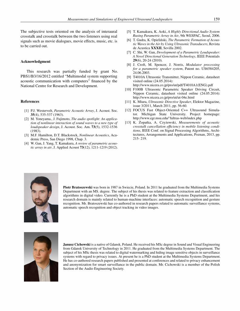
Janusz Cichowski is a native of Gdansk, Poland. He received his MSc degree in Sound and Visual Engineeringfrom Gdansk University of Technology in 2011. He graduated from the Multimedia Systems Department. Thesubject of his MSc thesis was related to digital watermarking and hiding image sensitive objects in surveillancesystems with regard to privacy issues. At present he is a PhD student at the Multimedia Systems Department.He has co-authored research papers published and presented at conferences and related to privacy enhancementand anonymization for smart surveillance in the public domain. Mr. Cichowski is a member of the PolishSection of the Audio Engineering Society.

160 P. Bratoszewski, J. Cichowski, A. Czyzewski
Andrzej Czyzewski is a native of Gdansk, Poland. He received his MSc degree in Sound Engineering fromthe Gdansk University of Technology in 1982, his PhD degree in 1987 and his DS. degree in 1992 fromthe AGH University of Science and Technology in Krakow. He joined the staff of the Sound EngineeringDepartment of Gdansk University of Technology in 1984. In December 1999, the President of Poland grantedhim the title of Professor. In 2002, the Senate of his University approved him to the position of Full Professor.He is author of more than 400 research papers published in international journals or presented at congressesand conferences around the world. In 1991, he published a monograph devoted to digital audio operations,and in 1998 he published in Poland his book entitled "Digital Sound" which won him the Prize of Ministryof Education of Poland. He is also author of 10 Polish patents in the domain of computer science and 5international patent applications. Prof. Czyzewski serves as Head of the Multimedia Systems Department ofGdansk University of Technology; Director of the Doctoral Studies (1994–2007) at the Faculty of Electronics,Telecommunications & Informatics. He holds Fellowship of the Audio Engineering Society and he is a memberof: IEEE, International Rough Set Society, and others.
CMST 21(3) 151-160 (2015) DOI:10.12921/cmst.2015.21.03.006