ENGINEERED WASTE MANAGEMENT PLAN (EWMP)
56
-11 , CoD5 · G"G K. t:.- / ~- 0 .::,- ~ r,1- 1·1·1 1• r· /'· OQ .'.. 1 • J , : ; J i;1, I· ENGINEERED WASTE MANAGEMENT PLAN (EWMP) ,4cc.e?Te~ (o - Jo -05 D & S Dairy at 13905 Bon View Avenue and 7777 Schaefer Avenue Ontario, California JN 97-34-05 June 13, 2005 Prepared by: ASSOCIATED ENGINEERS 3311 E. Shelby Street Ontario, CA 91764 (909) 980 - 1982
-
Upload
khangminh22 -
Category
Documents
-
view
1 -
download
0
Transcript of ENGINEERED WASTE MANAGEMENT PLAN (EWMP)

-11
,CoD5 · G"G K. t:.-/ ~- 0 .::,-
~r,1- 1·1·1 1 • r· /' · OQ .'..
1 • J , ~ : ; J i;1, I ·
ENGINEERED WASTE MANAGEMENT PLAN (EWMP)
,4cc.e?Te~ (o- Jo- 0 5
D & S Dairy at 13905 Bon View Avenue and 7777 Schaefer Avenue
Ontario, California JN 97-34-05
June 13, 2005
Prepared by:
ASSOCIATED ENGINEERS 3311 E. Shelby Street
Ontario, CA 91764 (909) 980 - 1982

.,. r.- • ,.-. - . I , , .1,' l .. ·- .
...., . ~ G Associafd Engineers, Inc. CONSUL TING CIVIL ENGINEERS
3311 E SHELBY STREET, ONTARIO. CA 91764-4872 (909) 980-1982 FAX (909) 941-0891
l- --; ~-'( , ;
Date: Januc:iry ·16. 2006 ~
\
' ; .J
,· : i I
CERTIFICATION
1<1...- '_,() r .
1;;: ---~ ~ ·, il(?df&-:
r~1~ ! , - ·-j
I certify that I have examined the facilities at the dairy located at 13905 Bon View Avenue and 7777 Schaefer Avenue, Ontario, California, and have found the dairy to be substantially in compliance with the Engineered \/\faste Management Plan. dated 14-June-05. .. . , , .;,
James L. Elliott, P.E.
Registration No. 43907 Expiration Date 6-30-07
State of California
7? u R-5> - t/ / ( ;(} 1 )f -,L ,; ) .',"-J( ( ·
-~ DUR v.s . -~·¢ 'flt (,
~ Ar C,<:>'1 91.ff - 331-.ST T(UL f-/1 ,i,t r 1-fA.UE- f_EITE.£._ 0~ Fl Ll CE.IL-, c FY<tDG Bo ( ff J>A
1 ~' rS, :.r{r: c 1:;1_1__-? ,1~~·, 'i/1L1 r/ •..
£)1.-scu>S ~~~3~.JS~$ u--r. £ ,J '')Jo _0«- ~11 FIL.c_ J,. _;c ~ !:,,"'-I _1 I F , ' ( .E. (~ ;. !f \ l.-Jc--i 1 <" "' -
L. J. r- · I\ ,r-.•< · J-><. 1 1-L tJ ;\.1 f, i ~ : ·
PLANNING DESIGNING SURVEYING

. ,.( .,_~0 . Associat&u Engineers, Inc.
•
0 331 1 E SHELBY STR EET. O NTARIO . CA 91 764-4872 Q--
'.' <$' ·,J. , . 1!1 r, i , '\
Date : Januziry 16. 2006
CERTIFICATION
--..,
CONSUL T ING CIVIL ENGINEERS
(909) 980-1982 FAX (909) 941 -089 1
It·;. _J ~ .i ~1(-2tf.&, - - - !--r'K: ,~~poi-
/ r- -1 I certify that I have examined the facilities at the dairy located at 13905 Bon View Avenue and 7777 Schaefer Avenue, Ontari o, California, and have found the dairy to be substantially in compliance with the Engineered 1/\/aste Management Plan, dated 14-June-05. .. ' " , .;,
James L. Elliott, P.E.
Registration No. 43907 Expiration Date 6-30-07
State of California
PLANNING DESIGNING SURVEYING

0
0 q..
Associafd Engineers, Inc. 3311 E SHELBY STREET. ONTARIO. CA 91764-4872
., er e • I ~ • , I
i.. __ --' I I
~-
CONSUL TING CIVIL ENGINEERS
(909 ) 980-1982 FAX (909) 941-0891
I ·7 ~ ........ lJ
t -) ~ . . (.) r
i:,· ;: -:-~ )"
Date: Januc:iry '16 . 2006 • I
.. l
'/ I
' !
CERTIFICATION
~ ·,-~l(-?d(&.
F4 =~~~ --~
,i-----.:--4-· 1 .~ · --3 I certify that I have examined the facilities at the dairy located at 13905 Bon View Avenue and 7777 Schaefer Avenue, Ontario, California, and have found the dairy to be substantially in compliance with the Engineered \/\/aste Management Plan. dated 14-June-05. . . , " , ...
James L. Elliott, P .E.
Registration No. 43907 Expiration Date 6-30-07
State of California
PLANNING DESIGNING SURVEYING

~ CERTIFICATION
I certify that I have examined the facilities at the dairy located at 13905 Bon View A venue and 7777 Schaefer A venue, Ontario, California, and have found the dairy to be substantially in compliance with the Engineered Waste Management Plan, dated 13-June-05.
James L. Elliott, P.E.
Signature of Registered Civil Engineer
Registration No. 43907 Expiration Date 6-30-05
State of California
- ~ -11
r

TABLE OF CONTENTS I I
Engineer's Certification
I. INTRODUCTION
A. Purpose .. ..... ... ....... ..... ........................ ......................... .... . .1-1
B. Current Regulations .............. .. ... ......... .. .. ........................ .1-1
C. Facility Location .... ..... ............................ .. .... .................. .I-1
D. Facility Description .. ... .. ... .... .............................. .. .......... . .1-1
E. Facility Operations ... .... .. ............ ............ ........ ...... .. ... ...... .1-1
F. Land Owner ......... ... ......... ........ .......... .... ...... ... .... ... .... ..... . I-3
II. DESIGN
A. Approach ...................................... ...... ....... . ... ... ..... II-1
B. Site Characteristics ............... ... ......................................... II-1
1. Evaporation .......................... .................... ....... .. ........ .II-1
2. Rainfall ..... ....... ...... ..... ...... .... ....... ........................ .... ... II-2
3. Operational water use ........ .................... .............. ..... II-2
4. Soil type ............................... ................... ... ............... II-4
5. Infiltration ......................... .. ... .. ...... ........ .................. .II-4
6. Runoff yield ..... .... ..................................................... II-4
7. Storage Ponds ....... ... .......... ... .. ... ... ................ ............. II-4
C. Pond Inflows ....... ... .. .......... .... ........ .................. ............... .II-4
D. Pond Outflows (disposal) ... ........... .......... ............... ...... ... II-5
E. Storage Requirements ........................ ... .. ............... ...... ... II-6
III. PLOT (SITE) PLAN
A. Property Description ................................. ................ ...... .III-1
B. Existing Topography ....................... ..... ........ ........ ...... .... .III-1
'U:.Su+"'!t£531SZ'.!22 _ D +; q _E2l'£1:--¥ ';EE-- -------= _ . JJ.W'"!f! .... •::a:... ., ... e-,

-( - l C. Proposed Improvements ... ............... ... .......... .... .......... .... . III-1
D. Drainage Patterns .. ............... .. ..... .............. .... .. .. .. ..... .. .. .. .III-I
IV. CONSTRUCTION A. Berms ...... ......... .. ....... . .. ...... ....... ... .. .................. ............. ... IV -1
B. Ponds .. ... .......... .. ................ ..... ..... ................ ....... ....... ..... . IV-1
C. Required Repairs .. .. ... .. ..... .... .. ......... .......... ... .... .... .. ..... .... IV -1
V. OPERATION & MAINTENANCE A. Preparation for Winter ................. .... ... ..... .... .................... V-1
B. Operational Water Use ...... ............... ... ......... .. .. ............... V -1
C. Pumps ........ ....... ................ ..... .... .... .. ... ......... .... ... ..... ... .. ... V-1
D. Rodent Control .... .. ...... ...... .. ...... .. .. ..... .................. .. ......... V-2
E. Solids Removal ............ .......... ...... ..... .. .... ...... ....... .. ..... .... V-2
F. Stagnant Water ................... ... .. ... ..... ................................ V-2
G. Inspections & Maintenance ....... ............ ..... ... ...... ... .. ....... V-2
H . Dairy Solid Waste (Manure) ... ... ... .................................. V-3
I. Weed Abatement ............. .. ... .... .. ........... ... ... .. .... .. ...... ...... V-3
J. Emergency Spill Plan .... ... . ...... .... .. ..................... V-3
VI. RECOMMENDATIONS .. .. ....... ......... .. ... ... .. .. ...... ... .. ... ...... VI-1
VII. CHECKLIST ..... ... .. .. ..... .. .. ...... .............. .. .......... ........ VII-1
APPENDICES

..... ~ .~~~.-·
SECTION I INTRODUCTION
A. Purpose:
The purpose of this EWMP is to provide a wastewater management system that is designed, constructed, operated and maintained to comply with the wastewater containment requirements in Order No. 99-11.
B. Current Regulations:
This plan has been prepared in accordance with the Santa Ana Regional Water quality Control Board's (SARWQCB) "Guidelines for the Development of Engineered Waste Management Plans for Concentrated Animal Feeding Operations (Dairies and Related Facilities)" dated February 2001 (these guidelines supercede the previous guidelines that were included as Attachment "B" in Order No. 99-1 1, NPDES No. CAG018001).
C. Facility Location:
The facility addressed by this Engineered Waste Management Plan (EWMP) is located at 13905 Bon View Avenue and 7777 Schaefer Avenue, Ontario, CA. As shown in Figure I-1, this site is located in the southwest comer of San Bernardino County.
D. Facility Description:
The project site covers 75.9 acres and contains 3 dwellings, 2 milking barns, corrals and 8 bermed pond/containment areas labeled Pl through P4, and P6 through P9 as shown in Exhibit A (located at the back of this report). Two areas labeled Dl and D2 are used for disposal. Water is dispersed across the top of these areas, thus allowing the water to evaporate and infiltrate as it spreads across them.
E. Facility Operations:
The facility is operated as a dairy with an animal population of 1480 cows. By lease agreement the operator of this facility is prohibited from exceeding this population. This EWMP has been prepared for this maximum population.
Process/wash water generated from 780 cows drains from the northern milk barn by gravity into pond P2. A fixed pump allows water from P2 to be pumped into P 1 and/or to disposal areas D 1 and D2 as shown in Exhibit A.
I-1
ll

I-2
Figure 1-1
LOCATION MAP

-
Process/wash water generated from 700 cows drains from the second milk barn to a sump pump located just south of the barn. From this sump the process water can be pumped into ponds P3, P6 and/or P7.
Floating pumps within Pl and P3 allow the transfer of water to pond P2 for disposal on areas Dl and D2. A fixed pump station at P2 conveys water to Dl and D2 via an existing system of 4" and 6" lines as shown on Exhibit A.
The current operator is D & S Dairy. The person responsible for implementing and maintaining this EWMP is David Vander Schaaf. He can be reached at (909) 947-3315.
His address is: 7777 Schaefer A venue Ontario, CA 91761
An alternate contact person when David Vander Schaaf is not available is Shirley Vander Schaaf. She can be reached at (909) 947-3315.
Her address is: 7777 Schaefer A venue Ontario, CA 91761
F. Land Owner:
The County of San Bernardino owns the property. The contact person responsible for implementation and maintenance of this EW"MP (in the event of failure of the facility operator to do so) is Chuck Hale. He can be reached at (909) 464-0186.
His address is: Southern California Agricultural Land Foundation 13839 Bon View Avenue Chino, CA 91710
1-3
f F
I
t
I l ~ !

SECTION II
DESIGN
A. Approach:
All runoff as well as all process wastewater generated within the project site is to be captured and disposed of on-site. In accordance with the guidelines, disposal of the captured wastewater and runoff plus maintenance of the ponds and equipment must be accomplished before the start of the next year's wet season (November-March). To be conservative, rainfall is assumed to occur at the end of this 150 day wet season, thus reducing the time for disposal to a minimum.
In accordance with the guidelines, both average aimual stonns and one 25-year stonn were assumed to occur during one wet season. Runoff from these storms was calculated in accordance with the San Bernardino County Hydrology Manual. For the purposes of these runoff calculations, it was assumed that the 25-year storm woµ ld precede the average annual storms, thus raising the Antecedent Moishire Content (AMC) normally used with these storms, AMC I, to the level prescribed for a 25-year sto1m, AMC II.
The proposed plan requires diversion of all off-site runoff. An existing system of eaiihen berms and asphalt barriers along the north and east sides of the site prevent offsite storm runoff from ente1ing the dairy.
B. Site Characteristics:
1. Evaporation - The rate of evaporation from the surface of ponded wastewater was estimated using California Irrigation Management Information System (CIMIS) data provided by the Department of Water Resources (D\VR). A map of "Reference EvapoTranspiration (ETo )" values throughout the state was obtained from DWR's Division of Planning and Local Assistance website (www.dpla.water.ca.gov). A copy of this map is provided in Appendix A. The project is located within "Reference EvapoTranspiration (ETo) Zone 9. D\VR was contacted for an appropriate "Kc" factor to be applied to these reference values. They estimated that with "dirty" runoff typical of the s]airy, the Kc would be 1.1 or 10% higher than the reference values. The reference value of ETo for Zone 9 is 55.1 inches per year: 41.58 inches during the 7 dry months from April to October and 13.56 inches dming the 5 wet months from November to March. Applying the Kc to the dry-season average reference value results in a projection of (1 . l x41 .58) 45.74 inches of evaporation from ponded wastewater for the 215-day dry season, or
II-1
0.0177 feet/day. Likewise, applying the Kc to the wet-season average reference value results in a projection of (1 . lx 13.56) 14.92 inches of evaporation from ponded wastewater for the 150-day wet season, or 0.0083 feet/day.
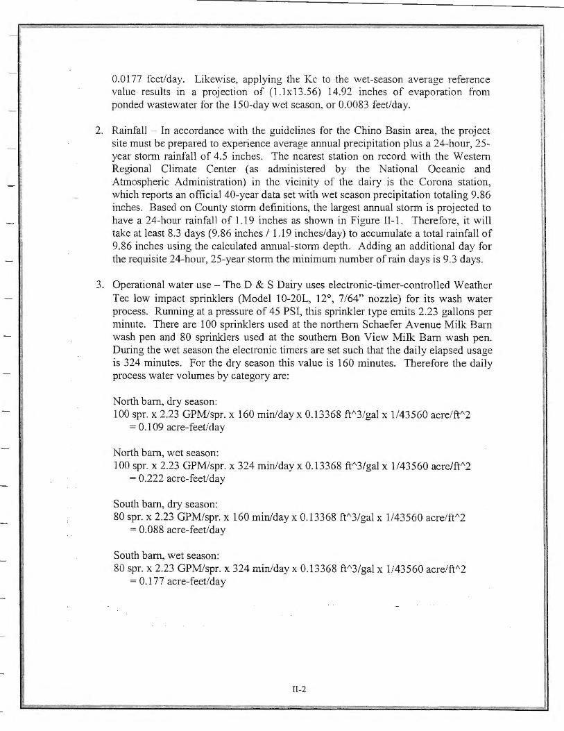
2. Rainfall - In accordance with the guidelines for the Chino Basin area, the project site must be prepared to experience average annual precipitation plus a 24-hour, 25-year storm rainfall of 4.5 inches. The nearest station on record with the Western Regional Climate Center (as administered by the National Oceanic and Atmospheric Administration) in the vicinity of the dairy is the Corona station, which reports an official 40-year data set with wet season precipitation totaling 9.86 inches. Based on County storm definitions, the largest annual storm is projected to have a 24-hour rainfall of 1.19 inches as shown in Figure II-1. Therefore, it will take at least 8.3 days (9.86 inches I 1.19 inches/day) to accumulate a total rainfall of 9.86 inches using the calculated annual-storm depth. Adding an additional day for the requisite 24-hour, 25-year storm the minimum number ofrain days is 9.3 days.
3. Operational water use - The D & S Dairy uses electronic-timer-controlled Weather Tee low impact sp1inklers (Model 10-20L, 12°, 7/64" nozzle) for its wash water process. Running at a pressure of 45 PSI, this sprinkler type emits 2.23 gallons per minute. There are 100 sprinklers used at the northern Schaefer A venue Milk Barn wash pen and 80 sprinklers used at the southern Bon View Milk Barn wash pen. During the wet season the electronic timers are set such that the daily elapsed usage is 324 minutes. For the dry season this value is 160 minutes. Therefore the daily process water volumes by category are:
North barn, dry season: 100 spr. x 2.23 GPM/spr. x 160 min/day x 0.13368 ff'3/gal x 1/43560 acre/ft"2
= 0.109 acre-feet/day
North barn, wet season: 100 spr. x 2.23 GPM/spr. x 324 min/day x 0.13368 ft"3/gal x 1/43560 acre/ft"2
= 0.222 acre-feet/day
South barn, dry season: 80 spr. x 2.23 GPM/spr. x 160 min/day x 0.13368 ft"3/gal x 1/43560 acre/ft"'2
= 0.088 acre-feet/day
South barn, wet season: 80 spr. x 2.23 GPM/spr. x 324 min/day x 0.13368 ft"3/gal x 1/43560 acre/ft"2
= 0.1 77 acre-feet/day
II-2
I I

-~ FIGURE 11-1
RAIN DEPTH VERSUS RETURN PERIOD
7.00
6.00 C: ---' 5.00 --' < ~ 4.00 <i: 0:: 3.00 --' < b 2.00 f,-
1.00
0.00 1
1
I -.- 24-hr storm l
10
RETURN PERIOD (years)
II-3
5.9
100
r.
- Ii
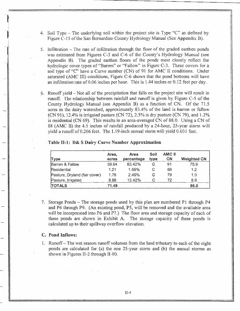
4. Soil Type - The underlying soil within the project site is Type "C" as defined by Figure C-15 of the San Bernardino County Hydrology Manual (See Appendix B).
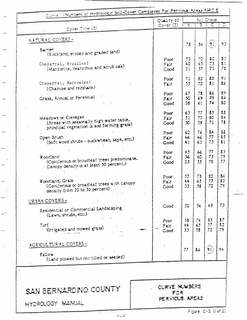
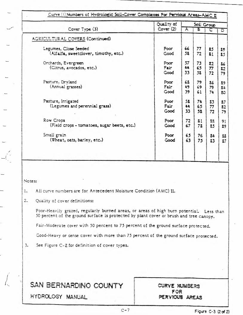
5. Infiltration - The rate of infiltration through the floor of the graded earthen ponds was estimated from Figures C-3 and C-6 of the County's Hydrology Manual (see Appendix B). The graded earthen floors of the ponds most closely reflect the hydrologic cover types of "Barren" or "Fallow" in Figure C-3. These covers for a soil type of "C" have a Curve number (CN) of 91 for AMC II conditions. Under saturated (AMC III) conditions, Figure C-6 shows that the pond bottoms will have an infiltrntion rate of 0.06 inches per hour. This is 1.44 inches or 0.12 feet per day.
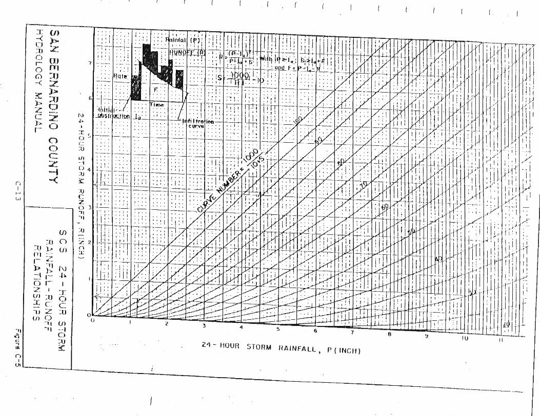
6. Runoff yield - Not all of the precipitation that fall s on the project site will result in nmoff. The relationship between rainfall and runoff is given by Figure C-5 of the County Hydrology Manual (see Appendix B) as a function of CN. Of the 71.5 acres in the dairy watershed, approximately 83.4% of the land is ban·en or fallow (CN 91), 12.4% is irrigated pasture (CN 72), 2.5% is dry pasture (CN 79), and 1.2% is residential (CN 69). This results in an area-averaged CN of 88.0. Using a CN of 88 (AMC II) the 4.5 inches of rainfall produced by a 24-hour, 25-year storm will yield arunoffof0.266 feet. The 1.19-inch annual storm will yield 0.031 feet.
Table 11-1: D& S Dairy Curve Number Approximation
Area, Area Soil AMC II Type acres percentaoe tvpe CN Weighted CN Barren & Fallow 59.64 83.42% C 91 75.9 Residential 1.21 1.69% C 69 1.2 Pasture, Dryland (fair cover) 1.76 2.46% C 79 1.9 Pasture, lrrioated 8.88 12.42% C 72 8.9
!TOTALS 71 .49 88.0
7. Storage Ponds - The storage ponds used by this plan are numbered Pl through P4 and P6 through P9. (An existing pond, PS, will be removed and the available area will be incorporated into P6 and P7.) The floor area and storage capacity of each of these ponds are shown in Exhibit A. The storage capacity of these ponds is calculated up to their spillway overflow elevation.
C. Pond Inflows:
1. Runoff - The wet season runoff volumes from the land tributary to each of the eight ponds are calculated for (a) the one 25-year storm and (b) the annual storms as shown in Figures II-2 through II-10.
II-4
l t

_f:
2. Operational water - Water volumes generated dming the n01mal operation of the dairy are calculated in Section II.B.3. These volumes vary for the two on-site milk barns and for the wet and dry seasons. The operation water is also known as process water or wash water. Process water from the northern milk barn can be directed to Pond 1 or Pond 2. Process water from southern milk barn can be directed to Ponds 6 or 7. The numbers of days of operational water received by each pond during the wet and dry seasons are shown in Figures II-2 through II-10.
3. Soli.ds - In accordance with the guidelines, it is estimated that 10 percent of the solid waste produced by the animals will be transported into the containment ponds by both process water and stormwater runoff. These solids decrease the effective volumes of the ponds. The manure production rate used in this report is the conservative value of 1.7 cubic feet per animal unit (AU) per day for lactating cows, as reported by the University of Maryland. Given that an AU is defined as a 1,000-pound animal and that an average cow weighs 1,400 pounds, manure production rate is 2.38 cubic feet per cow per day. When water is transferred from one pond to another by means of pumps, it is assumed for the purposes of this analysis that only the water content is transferred. When a pond overflows into an adjacent one, it is assumed that the cause is a large storm event and that suspended solids will be conveyed with the runoff water. Detailed transfer infmmation can be found in Figures II-2 through II-10.
D. Pond Outflows (disposal):
1. Rain day infiltration - It is assumed that the site will received rainfall a minimum of 9.3 days per year. As the 24-hour storm runoff estimates already account for infiltration (by the reduction of rainfall to runoff), no additional infiltration is assumed on these rain days.
2. Non-rain day infiltration - On non-rain days the amount of water disposed of through the bottom of the ponds and via irrigation of the disposal areas (D 1 and D2) equals the wetted area times 0.12 feet per day. Losses in Dl and D2 are accounted for in the Floor/Disposal Area of pond P2 as shown in Figure II-3.
3. Evaporation - Ponded water is also subject to evaporation. In this analysis, evaporation is applied whenever (a) a storage basin has ponded water present and (b) the site is not currently expe1iencing precipitation. The dry season average daily rate of evaporation is 0.0177 feet per day, and the wet season average daily rate is 0.0083 feet per day.
Since this analysis applies the "worst-case" scenario of all the storms occurring at the end of the wet season, the only source of water during the rest of the wet season is the process water. Hence, du1ing the wet season the combined infiltration and evaporation rate is restrained to the amount of water inflow, that being the process water.
II-5
1 I
r i

l During the dry season, both the infiltrative and the evaporative losses are applied as long as water is still present from the wet season storms. The total loss rate, offset by the daily dry season process water inflow rate, is divided into the peak wet weather storage volume to calculate the maximum time to evacuate each pond. As shown in Figures II-2 through II-10 the required time varies from 16 to 52 days. The ponds, therefore, will be dry long before the end of the 215-day dry season.
E. Storage Requirements:
1. Maximum Storage Requirements - The peak volume required in each pond occurs at the end of the last storm of the wet season. The total volume required is 57.74 AF (as calculated in Figures II-2 through II-10). The total volume provided by Pl through Pl9 is 57.85 AF. The accumulation of solids during the wet season is taken into account in the calculation of this maximum storage requirement.
2. Maximum Solids Storage - Solids will continue to accumulate during the dry season and will be transported to the ponds by the dry season process water. By the end of the dry season the volume occupied by solids within each of the ponds will reach a maximum value. The total volume of solids deposited is 3.0 AF as calculated in Figures II-2 through II-10.
II-6
t
i

FIGURE 11-2
SITE RUNOFF CONSTANTS
Topic Item Value Units Notes Solids Manure production rate 1.7 cf manure I AU / day From University of Maryland
Cow size 1.4 AU per cow Cow size: 1400lb animal / 1000 lb animal/AU !Manure production rate 2.38 cf manure I cow I day I
25-year storm P24 4.5 inches From Guidelines Cn 88 From "Curve Numbers.xis" s 1.364 per SBC Hydrology Manual Eq. C.2 la 0.273 per SBC Hydrology Manual Eq. C.1 Yj 0. 710 inch/inch per SBC Hydrology Manual Eq. C.3 y 3.196 inches
125-year Storm Yield 0.266 feet I Annual storm Ave. winter months rainfall 9.86 inches From Western Regional Climate Center
P24 (1-year storm) 1.19 inches/day per standard County rainfall log interpolations Days of winter rain 8.286 days Cn 88 From "Curve Numbers.xis" s 1.364 per SBC Hydrology Manual Eq. C.2 la 0.273 per SBC Hydrology Manual Eq. C.1 Yj 0.310 inch/inch per SBC Hydrology Manual Eq. C.3 y 0.369 inches
!Annual Storm Yield 0.031 feet I Process water North - summer O .109 acre-feet/day Provided by D & S Dairy ca lculations
North - winter 0.222 acre-feet/day Provided by D & S Dairy calculations South - summer 0.088 acre-feet/day Provided by D & S Dairy calculations South - winter 0 .177 acre-feet/day Provided by D & S Dairy calculations
Infiltration Infiltration rate 0.1 2 feet per day From SBC Hydrology Manual Figure C-6
Evaporation Summer base rate 0.0161 feet/day From CIMIS by Department of Water Resources Winter base rate 0.0075 feet/day From CIMIS by Department of Water Resources Kc factor 1.1 From Department of Water Resources Summer adjusted rate 0.0177 feet/day Winter adjusted rate 0.0083 feet/day
Water Calculations-2005.xls Factors
Season
Waler Calculallons-2005.xls
WET
DRY
1 2 3 4
5
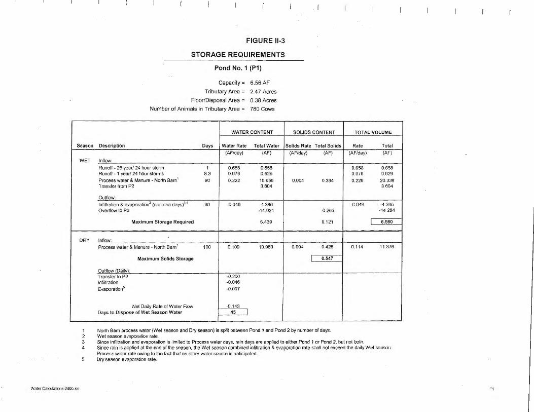
FIGURE 11-3
STORAGE REQUIREMENTS
Pond No. 1 (P1)
Capacity = 6.56 AF
Tributary Area = 2.47 Acres
Floor/Disposal Area = 0.38 Acres
Number of Animals in Tributary Area = 780 Cows
WATER CONTENT
Description Days Water Rate Total Water
(AF/day) (AF)
lnnow:
Runoff - 25 year/ 24 hour storm 1 0.658 0.658 Runoff - 1 year/ 24 hour stonms 8.3 0.076 0.629
Process water & Manure - North Barn' 90 0.222 19.956 Transfer from P2 3.604
Outflow:
Infiltration & evaporation2 (non-rain days)3•4 90 -0.049 -4.386
Overflow to P3 -14.021
Maximum Storage Required 6.439
lnnow:
Process water & Manure - North Barn' 100 0.109 10.950
Maximum Solids Storage
Outflow (Dailvl: Transfer to P2 -0.200 Infiltration -0.046
Evaporation5 -0.007
Net Daily Rate of Water Flow -0.143 Days to Dispose of Wet Season Water 45 I
SOLIDS CONTENT
Solids Rate Total Solids
(AF/day) (AF)
0.004 0.384
-0.263
0.121
0.004 0.426
I 0.547
North Barn process water (Wet season and Dry season) is split between Pond 1 and Pond 2 by number of days. Wet season evaporation rate.
TOTAL VOLUME
Rate Total
(AF/day) (AF)
0.658 0.658 0.076 0.629
0.226 20.339 3.604
-0.049 -4.386 -14.284
I 6.560
0.114 11 .376
Since infiltration and evaporation is limited to Process water days, rain days are applied to either Pond 1 or Pond 2, but not both. Since rain is applied at the end of the season, the Wet season combined infiltration & evaporation rate shall not exceed the daily Wet season Process water rate owing to the fact that no other water source is anticipated. Dry season evaporation rate.
P1

Waler Calculalions-2005.xls
Season
WET
DRY
1 2 3 4
5 6 7
FIGURE 11-4
STORAGE REQUIREMENTS
Pond No. 2 (P2)
Capacity = 5.49 AF
Tributary Area = 13.01 Acres
Floor/Disposal Area (incl. 0 1 & 02) = 6.16 Acres
Number of Animals in Tributary Area = 780 Cows
WATER CONTENT
Description Days Water Rate Total Water
(AF/day) (AF)
lnHow:
Runoff - 25 year/ 24 hour storm 1 3.465 3.465 Runoff - 1 year/ 24 hour storms 8.3 0.400 3.314
Process water & Manure - North Barn 1 60 0.222 13.304
Outnow:
Infiltration & evaporation2 (non-rain days)3•4
50.7 -0.222 -11.245 Transfer to P1 -3.604
Maximum Storage Required 5.234
lnnow:
Process water & Manure - North Barn 1 115 0.109 12.592 Transfer from P1 0.200 Transfer from P3 0.200
Maximum Solids Storage
Outflow /Dailvl: Infiltration -0.739
Evaporation• -0.109
Net Daily Rate of Water Flow6 -0.739
Days to Dispose of Wet Season Water7 52 I
SOLIDS CONTENT
Solids Rate Total Solids
(AF/day) (AF)
0.004 0.256
0.256
0.004 0.490
I 0.746
North Barn process water (Wet season and Dry season) is split between Pond 1 and Pond 2 by number of days. Wet season evaporation rate.
TOTAL VOLUME
Rate Total
(AF/day) (AF)
3.465 3.465 0.400 3.314
0.226 13.560
-0.222 -11.245 -3.604
I 5.490
0.114 13.082
Since Infiltration and evaporation is limited to Process water days, rain days are applied to either Pond 1 or Pond 2, but not both. Since rain is applied at the end of the season, the Wet season combined infiltration & evaporation rate shall not exceed the daily Wet season Process water rate owing to the fact that no other water source is anticipated. Dry season evaporation rate. Net rate after P1 and P3 are empty. Includes days to drain P1 and P3.
P2

Season
Water Calculations-2005.xls
WET
DRY
1 2 3 4
5
FIGURE 11-5
STORAGE REQUIREMENTS
Pond No. 3 (P3)
Capacity = 6.16 AF
Tributary Area = 6.97 Acres
Floor/Disposal Area (incl. D1 & D2) = 1.26 Acres
Number of Animals in Tributary Area = 0 Cows
WATER CONTENT
Description Days Water Rate Total Water
(AF/day) (AF)
Inflow:
Runoff - 25 year/ 24 hour stonn 1 1.856 1.856 Runoff - 1 year/ 24 hour storms 8.3 0.214 1.775
Process waler & Manure - North Barn 1 0 0.222 0.000 Overflow from P1 14.021
Outflow:
Infiltration & evaporation2 (non-rain days)'-4 0.0 -0.162 0.000 Overflow to P4 -11.583
Maximum Storage Required 6.070
Inflow:
Process water & Manure - North Barn 1 0 0.000 0.000
Max imum Solids Storage
Outflow (Daily): Transfer to P2 -0.200 Infiltration -0.151
Evaporation5 -0.022
Net Daily Rate of Water Flow -0.374 Days to Dispose o f Wet Season Water 16 I
SOLIDS CONTENT
Solids Rate Total Solids
(AF/day) (AF)
0.000 0.000 0.263
-0.172
0.090
0.000 0.000
I 0.090
North Barn process water (Wet season and Dry season) is split between Pond 1 and Pond 2 by number of days. Wet season evaporation rate.
TOTAL VOLUME
Rate Total
(AF/day) (AF)
1.856 1.856 0.214 1.775
0.222 0.000 14.284
-0.162 0.000 -11 .756
I 6.160
0.000 0.000
Since infiltration and evaporation is limited to Process water days, rain days are applied to either Pond 1 or Pond 2, but not both. Since rain is applied at the end of the season, the Wet season combined infiltration & evaporation rate shall not exceed the daily Wet season Process water rate owing to the fact that no other water source is anticipated. Dry season evaporation rate.
P3

Season
WET
DRY
1 2 3 4
5
Water Calculalions-2005.xls
r
FIGURE 11-6
STORAGE REQUIREMENTS
Pond No. 4 (P4)
Capacity= 0.26 AF
Tributary Area = 2.40 Acres
Floor/Disposal Area = 0.06 Acres
Number of Animals in Tributary Area = O Cows
WATER CONTENT
Description Days Water Rate Total Water
(AF/day) (AF)
Inflow:
Runoff - 25 year/ 24 hour storm 1 0 .639 0.639 Runoff - 1 year/ 24 hour storms 8.3 0.074 0.611
Process water & Manure - North Barn 1 0 0.222 0.000
Overflow rrom P3 11 .583
Outrlow:
Infiltration & evaporation2 (non-rain days)3•4 0.0 -0.008 0 .000
Overflow to P6 -12.577
Maximum Storage Required 0.257
Inflow:
Process water & Manure - North Barn 1 0 0.000 0.000
Max imum Solids Storage
Outflow /Dailv): Infiltration -0.007
Evaporation5 -0.001
Net Daily Rate or Water Flow -0.008 Days to Dispose of Wet Season Water 31 I
SOLIDS CONTENT
Solids Rate Total Solids
(AF/day) (AF)
0.000 0.000 0.172
-0.169
0 .003
0.000 0.000
I 0.003
North Barn process water (Wet season and Dry season) is split between Pond 1 and Pond 2 by number of days. Wet season evaporation rate.
TOTAL VOLUME
Rate Total
(AF/day) (AF)
0.639 0.639 0.074 0.611
0.222 0.000 0.000 11 .756
-0.008 0.000 -12.746
I 0.260
0.000 0.000
Since infiltration and evaporation is limited to Process water days, rain days are applied to either Pond 1 or Pond 2, but not both. Since storm runoff is applied at the end of the Wet season, the Wet season combined infiltration & evaporation rate shall not exceed the daily Wet season Process water rate owing to the ract that no other water source is anticipated. Dry season evaporation rate.
P4

Season
WET
DRY
1 2 3 4
5
Waler Calculalions-2005.xls
FIGURE 11-7
STORAGE REQUIREMENTS
Pond No. 6 (P6)
Capacity = 10.82 AF
Tributary Area = 26.06 Acres
Floor/Disposal Area = 3.33 Acres
Number of Animals in Tributary Area = 700 Cows
WATER CONTENT
Description Days Water Rate Total Water
(AF/day) (AF)
Inflow:
Runoff - 25 year/ 24 hour storm 1 6.941 6.94 1 Runoff - 1 year/ 24 hour storms 8.3 0.801 6.638
Process water & Manure - South Barn' 150 0.177 26.608 Overflow from P4 12.577
Outflow:
Infiltra tion & evaporation2 (non-rain days)3•4 140.7 -0.177 -24 .961
Overflow to P7 -17.265
Max imum Storage Required 10.538
Inflow:
Process water & Manure - South Barn 1 30 0.088 2.628
Maximum So lids Storage
Outflow (Dailvl: Infiltration -0.400
Evaporation5 -0.059
Net Daily Rate of Water Flow -0.371 Days to Dispose of Wet Season Water 28 I
SOLIDS CONTENT
Solids Rate Total Solids
(AF/day) (AF)
0.004 0.574 0.169
-0.461
0.282
0.004 0.115
I 0.396
South Barn process water (Wet season and Dry season) is split between Pond 6 and Pond 7 by number of days. Wet season evaporation rale.
TOTAL VOLUME
Rate Total
(AF/day) (AF)
6.941 6.941 0.801 6.638
0 .18 1 27.182 0.000 12.746
-0.177 -24.961 -17.726
I 10.820
0.091 2.743
Since infiltration and evaporation is limited to Process water days, rain days are applied to either Pond 6 or Pond 7, but not both. Since rain is applied at the end of the season, the Wet season combined infiltration & evaporation rate shall not exceed the daily Wet season Process water rate owing to the fact that no other water source is anticipated. Dry season evaporation rate.
P6

Season
WET
DRY
FIGURE 11-8
STORAGE REQUIREMENTS
Pond No. 7 (P7)
Capacity = 21.10 AF
Tributary Area = 5.63 Acres
Floor/Disposal Area = 4.39 Acres
Number of Animals in Tributary Area = 700 Cows
WATER CONTENT
Description Days Water Rate Total Water
(AF/day) (AF)
Inflow:
Runoff - 25 year/ 24 hour storm 1 1.500 1.500 Runoff - 1 year/ 24 hour slorms 8.3 0.173 1.434 Process water & Manure - South Barn 1 0 0.177 0.000 Overflow from P6 17.265
Outflow:
Infiltration & evaporalion2 (non-rain days)'-4 0.0 -0.177 0.000
Maximum Storage Required 20.198
Inflow:
Process water & Manure - Soulh Barn 1 185 0.088 16.206
Maximum Solids Storage
Outflow (Daily): Infiltration -0.527
Evaporation5 -0.078
Net Daily Rate of Water Flow -0.517 Days to Dispose of Wet Season Water 39 I
SOLIDS CONTENT
Solids Rate Total Solids
(AF/day) (AF)
0.004 0.000 0.461
0.461
0.004 0.708
I 1.1 69
1 South Barn process water (Wet season and Dry season) is split between Pond 6 and Pond 7 by number of days. 2 Wet season evaporation rate.
TOTAL VOLUME
Rate Total
(AF/day) (AF)
1.500 1.500 0.173 1.434
0.181 0.000 17.726
-0.177 0.000
I 20.659
0.091 16.913
3 Since infiltration and evaporation is limited to Process water days, rain days are applied to either Pond 6 or Pond 7, but not both. 4 Since rain is applied at the end of the season, the Wet season combined infiltration & evaporation rate shall not exceed the daily Wet season
Process water rate owing to the fact that no other water source is anticipated. 5 Dry season evaporation rate.
Water Calculations-2005.xls p7

Season
WET
DRY
FIGURE 11-9
STORAGE REQUIREMENTS
Pond No. 8 (P8)
Capacity = 1 .42 AF
Tributary Area = 2.72 Acres
Floor/Disposal Area = 0.22 Acres
Number of Animals in Tributary Area = 0 Cows
WATER CONTENT
Description Days Water Rate Total Water
(AF/day) (AF)
Inflow:
Runoff - 25 year/ 24 hour storm 1 0.724 0.724 Runoff - 1 year/ 24 hour storms 8.3 0.084 0.693
Process water & Manure - South Barn 1
0 0.177 0.000
Outflow:
Infiltration & evaporation2 (non-rain days)3·4 0.0 -0.028 0.000
Maximum Storage Required 1.417
Inflow:
Process water & Manure - South Barn 1 0 0.000 0.000
Maximum Solids Storage
Outflow (Dailv): Infiltration -0.026
Evaporation5 -0.004
Net Daily Rate of Water Flow -0.030 Days to Dispose of Wet Season Water 47 I
SOLIDS CONTENT
Solids Rate Total Solids
(AF/day) (AF)
0.000 0.000
0.000
0.000 0.000
I 0.000
1 South Barn process water (Wet season and Dry season) is split between Pond 6 and Pond 7 by number of days. 2 Wet season evaporation rate.
TOTAL VOLUME
Rate Total
(AF/day) (AF)
0.724 0.724 0.084 0.693
0.177 0.000
-0.028 0.000
I 1.417
0.000 0.000
3 Since infiltration and evaporation is limited to Process water days, rain days are applied to either Pond 6 or Pond 7, but not both. 4 Since rain is applied at the end of the season, the Wet season combined infiltration & evaporation rate shall not exceed the daily Wet season
Process water rate owing to the fact that no other water source is anticipated. 5 Dry season evaporation rate.
f
Waler Calculalions-2005.xls PB

Water Calculations-2005.xls
Season
WET
DRY
2 3 4
5
Description
Inflow:
FIGURE 11-10
STORAGE REQUIREMENTS
Pond No. 9 (P9)
Capacity= 6.27 AF
Tributary Area = 12.04 Acres
Floor/Disposal Area= 1.81 Acres
Number of Animals in Tributary Area = 0 Cows
WATER CONTENT
Days Water Rate Tota l Water
(AF/day) (AF)
Runoff - 25 year/ 24 hour storm 1 3.207 3.207 Runoff - 1 year/ 24 hour storms 8.3 0.370 3.067
Process water & Manure - South Barn 1 0 0.177 0.000
Outflow:
Infiltration & evaporation2 (non-rain days{4
0.0 -0.177 0.000
Maximum Storage Required 6.274
Inflow:
Process water & Manure - South Barn 1 0 0.000 0.000
Maximum Solids Storage
Outflow /Dailvl: Infiltration -0.217
Evaporation5 -0.032
Net Daily Rate of Water Flow -0.249 Days to Dispose of Wet Season Water 25 I
SOLIDS CONTENT
Solids Rate Total Solids
(AF/day) (AF)
0.000 0.000
0.000
0.000 0.000
I 0.000
South Barn process water (Wet season and Dry season) is split between Pond 6 and Pond 7 by number of days. Wet season evaporation rate.
TOTAL VOLUME
Rate Total
(AF/day) (AF)
3.207 3.21 0.370 3.07
0.177 0.00
-0.177 0.00
I 6.27
0.000 0.00
Since infiltration and evaporation is limited to Process water days, rain days are applied to either Pond 6 or Pond 7, but not both. Since rain is applied at the end of the season, the Wet season combined infiltration & evaporation rate shall not exceed the daily Wet season Process water rate owing to the fact that no other water source is anticipated. Dry season evaporation rate.
pg

SECTION III PLOT (SITE) PLAN
A. Property Description:
The D & S Dairy site is located on Lots 4, 20 and 29 of Rancho Santa Ana Del Chino, Section 17, Township 2 South, Range 7 West, San Bernardino Meridian, situated in the County of San Bernardino, State of California, as per map filed in Book 6, Page 15 of Maps.
B. Existing Topography:
Existing 1-foot and 2-foot contours were established throughout the project site by aerial photography and ground control survey as shown in Exhibit A.
C. Proposed Improvements:
1. Ponds - Excavation within P6, P7, and P9 will be necessary in accordance with Exhibit A to expand existing storage capacities to meet the requirements of this updated plan. The elevations of the existing berms around P6 and P7 need to be ve1ified and raised with respect to the overflow weir elevations as necessary to achieve desirable freeboard around the ponds. The grading improvements proposed for P6 and P7 include 20' ramps to provide vehicular access to the floors of the basins.
2. Grading - Minor grading is required to establish flow paths on the west and east sides of the facility as shown in Exhibit A.
D. Drainage Patterns:
1. Flow Paths - The natural ground slopes downhill to the south in this area. Existing berms at the north, west, and east property lines divert off-site flows from entering the site. A north-to-south ridge divides the northern corral area with flows going to P2 on the west side and southward along the east property line on the east side. The southern corrals are also divided with the northern most area draining northward into P3 and P4, while the remainder drains to the east. A 42" gravity pipeline on the east boundary of the property conveys the flows southward to an existing pond PS. Proposed earthwork will divide this existing pond into two sections that will be incorporated into P6 and P7. Under proposed conditions, the 42" pipe will outlet into P6. The process water from the north barn is collected in a sump located on the west side of the building and is conveyed by an existing gravity line to P2.
2. Pumping Equipment - The daily process water from the southern barn is pumped from a sump located south of the barn. Pipes ( 4" and 6") convey the pumped flow to P6 or P7 (or P3 if necessary). Floating pumps in Pl and P3 allow transfer of water to P2. A fixed pump station at P2 lifts the water to disposal areas Dl and D2
III-1
t
I
lo
~r -1
i t
"
via 4" and 6" lines as shown in Exhibit A. Outlets at the top of D 1 and D2 spread the water out across the width of these disposal areas.
III-2
(
I I l! II
I
SECTION IV
CONSTRUCTION
A. Berms
Berm improvements shall be constructed of native soils with no organic or deleterious material. They are to be buttressed into the existing soils to a minimum depth of 12 inches to help avoid a shear plane between the base of the berm and the existing surface. Maximum fill slopes shall not exceed 2: 1. Construction shall be performed in such a manner so that lifts do not exceed 6 inches. All fill placed in berms and all other areas shall have not less than 90 percent relative compaction as determined by ASTM D-1557-91 (see Appendix C).
B. Ponds
The proposed grading improvements shall be constructed of native soils. Any organic wastes and other deleterious materials shall be removed prior to construction of proposed improvements.
IV-1
l

- ·,
SECTION V
OPERATION AND MAINTENANCE
A. Preparation for Winter
In addition to the weekly inspections of all berms, basins, pond appurtenances and pond depths, the Dairy Operator shall inspect all containment structures prior to November of each year to assure that the maximum capacity is available prior to the start of the wet season. Any deficiency from the design capacity indicated in Exhibit A shall be immediately corrected by pumping, solids removal, or other means. A check list for prewinter operational inspections is attached at the end of this section. Du1ing the wet season, process water should be managed on a daily basis to maximize the volume of available containment capacity.
The ponds and disposal areas shall be plowed and upturned to a depth of 18 inches to maintain maximum infiltration into the ground. This procedure should be performed once at the end of the wet season and once prior to the beginning of the wet season, or twice per year at a minimum. All soils collected within the ponds must be removed prior to plowing.
B. Operational Water Use
The Operator shall perform all tasks necessary to minimize the volume of wash water used, including but not limited to, turning off all washing and flushing hoses and sprinklers when not actively in use.
C. Pumps
The pumps, intakes, and transfer system shall be inspected prior to and weekly during the wet season to ensure proper operation of the pumping system. These inspections shall include operation of the pump to insure it is still meeting manufacturer's specifications. The Dairy shall provide a diesel generator for standby power, or other equally effective power source, to ensure the pumps remain operational at all times. Spare motors, pumps, and other parts shall be available in the event of a system failure.
V-1
I
l t

'
D. Rodent Control
The Dairy Operator shall inspect all parts of the facility for evidence of rodent infestation. Rodents, primarily gophers and ground squirrels, will be eradicated by qualified licensed pest control professionals. Inspections shall be conducted on a weekly basis and daily during the wet season, following the first significant rain.
E. Solids Removal
As soon as is practicable following the ending of the wet season, solids shall be removed from the containment basins to restore the minimum required available capacity of the basins prior to the next wet season. The anticipated volumes of annual, in-pond solids accumulation are 1isted in Figures II-2 to II-10.
F. Stagnant Water
Any other low-lying areas within any part of the Dairy facility which may capture and retain ponded water shall be filled and/or graded to prevent the accumulation of ponded water. This will reduce potential insect and health nuisance conditions.
G. Inspections & Maintenance
Inspections of all berms, basins, pond appurtenances, and pond depths shall be made by the Dairy Operator on a weekly basis. These inspections shall be made daily during the wet season after the beginning of significant rainfall. An inspection shall also be made fo llowing any rainfall at any time which causes runoff. A log book shall be kept by the Dairy Operator with the results of each inspection and any necessary follow-up remedial actions taken, and such information shall be submitted to the proper agencies when required or requested.
The weekly inspections are for the purpose of providing assurance that all containment structures are intact and that all equipment is in proper operating condition and shall include, but not be limited to, inspections of ponds, berms, concrete curbs, vehicle access points, stand-by electrical power facilities, pump and valves, piping systems, low-lying locations which contain stagnant water, runoff channels and swales, signs of rodent infestation, weed growth, and erosion.
The detailed inspection performed immediately prior to the wet season shall be for the primary purpose of ensuring that the ponds have maximum capacity available and that all equipment is in proper operating condition. The basic (minimal) requirements for this inspection are enumerated in Section V (A) "Preparation for Winter," and shall also include (a) checking the depths and areas of all ponds, (b) verifying the functionallity of all electrical and motorized equipment including stand-by and spare parts equipment, and ( c) removal and proper disposal of all solids from the ponds to ensure maximum storage capacity.
V-2
l

r
'--
.__
-
'-
Daily inspections during the wet season shall include (a) checking freeboard on each pond and making any necessary adjustments, (b) checking the full cycl ing-operation of all equipment, and (c) checking for signs of erosion along the berms and channels.
H. Dairy Solid Waste (Manure)
Records of manure disposal shall be maintained in accordance with standard manure tracking procedures and shall include the hauler's name, the date, and the amount of manure hauled from the site. This information shall be reported on the Annual Report of Animal Waste Discharge to be submitted to SARWQCB, togther with the standard "Hauling Manifest" signed by the waste hauler. No on-site storage or disposal areas for manure are permitted.
I. Weed Abatement
At any such time as weed removal is necessary (a) to maintain a clear spillway discharge flowpath, (b) to provide convenient access to containment structures, or ( c) to maintain the efficient distribution of wastewater, the Dairy Operator shall take such measures as are necessary to abate this condition. The dicharge spillway for P8 located at the southwest comer of the property is particularly important as it is the emergency point of discharge from the facility.
J. Emergency Spill Plan
In the event of an emergency spill, the Dairy Operator shall notify all mandatory regulatory and permitting agencies as required by law and shall then endeavor to immediately abate the causes of the spill and to then repair any damaged facilities caused by the spill.
The following is a list of local private contractors who can be called upon for assistance in these tasks:
Dairy Services:
Pumps and Wells:
Vandenberg Manufacturing Services 16455 Chino Corona Road Chino, CA 909/597-3412
Groom ans Pump & W el 1 Drilling 16541 Chino Corona Road Chino, CA 909/597-1452
Cleaning & General Repair: Rote-Rooter 319 Union A venue Pomona, CA 909/397-0567
V-3
I I I
-
SECTION VI
RECOMMENDATIONS
The following items are recommended to bring the dairy located at 7777 Schaefer A venue, Ontario, California, 91761, into compliance with the current SARWQBC requirements, as shown on Exhibit A:
1. Grade specified grade-to-drain areas as indicated on the proposed site plan.
2. Expand the capacity of ponds P6, P7, and P9 by expansion and excavation as noted on Exhibit A. Construct 20' -wide access roads as indicated to provide vehicular access to the pond bottoms of ponds P6 and P7.
3. Maintain berm elevations around P7 at elevation 695.4 feet to provide 0.8 feet of freeboard above the outlet spillway flowline elevation.
4. Maintain berm elevations around P6 at elevation 696.8 feet to provide 0.8 feet of freeboard above the outlet spillway flow line elevation.
VI-1
-t
l l l
-1
..._
SECTION VII
CHECKLIST
Pre-Wet Weather Inspection:
Prior to the beginning of the wet season (November - March), the following items sha1l be performed:
• Maintenance service on all motors and pumps.
• Inspection of the transfer piping systems including the manual operation and cycling of all valves. This inspection should include operation of the system at maximum operating levels.
• Verification of pond capacity and freeboard inspection (i. e. soundness and elevation of embankments above spillway crests).
• Inspection and maintenance of berms and ponds.
• Plowing or turning up of the disposal and basin areas to a depth of 18 inches to ensure maximum efficiency of infiltration during the wet cycle .
VII-1
I

APPENDIX A
CIMIS EvapoTranspiration (Eto) Map

i .
MO D O C I I I I\ I Y O U
10 .--13 7
S ,IJ_,.A I I A l A I I l N
JIUN ITV
14 .~ I [ H A M A
13 ...... fl LU M A I
wr NO O(; I NO OLlH~12· Ull[ -: ..
7 S1E•nu
4 N(YAOA I .. , , .... i-···
C OL U SA ~ ..... \ ,-W-1, ~l II LA O I A
L A M.( "'°•' \;, !' -
Y0L0o·· I.--· I L
0D O ftAOO
1~4 ~'io,o AMADOR
. ,· --· 5 . S OL A NO 7·- _, . . -· ~ lfl 2i ' . CAlAYEAO ~ 'I I • ° CONIMA - • rx •. COU~ S AN ... _It (~r .. lAMIO• ,o,ou,N
~ ~- SfANlllAUI
I ~... ' <'(J 3 1Aff1A
~r4
Cl.AAA -.s;,~ MAOCII,\
12
8 NA PA ALP1N (
11 , . f UO L UMNli
MARl l'IOIA
MtffCfO
..: 15
·--
... BCHlfO
.l2 . 16
M. I N G $
18 I "' LU 11
10
O•I I PO Califomia Jtrlgation Management Information System (CIMIS)
REFERENCE EVAPOTRANSPIRATION 3 IAN IA B AIII I AIU,
.-
15
Reference EvapoTranspiration (ETo) Zones
rrJ=.i,~'!'::J~:r ... _ ... . _,.w; ~ ~~;.~-::.;~~t~~ ...... ,,.,·--~ 0~.r:::~~~cm¢...:r....1 ~ ;~-:..-;.~ .. ~~:.. m ~~~~~'r'4•N0•;0H:Wco.510M .. t>i., @l~"~ll:~~--1=:~"'/:'
r!Je.~::.~7-::.::::.::-:-l~ Cf m~~"j~~"
~=~re~II-.. ---~~• ~=!r=':S':~=
@]~~--:~:~~~LM,WJtC,IIWN ~ ~~i::.=-;1~·~:;.~".-=t~·-·~ ~-·- '···- -1741 .. mllll'lll0.1J(U11Vit'1~ ~ ~r&-~':.a~a~n,"OOA-U4;
[!]~=~~'!:$~--._"':: .. .._._, ... __ (!z]t:":~~,~·~~-.... -···-· [!]~~=~=,.~~~;;.!..,~~ i:;-;:;t"_!(II ... VIIII.O Ol'".-':H~\1.1{'0,\,'J) JlllO H•nt ~;::""'-::'-"'"'-'""'· .. ·re.--
M ON 0
14
Month!¥ ....... ,. n.MIDNIII c .... COIIINIDl!lllon I en, z- inc:hell/tllof!lh)
i'-r9~~ ,!':. ~ l~tl;-1-1;, ~I~~ ~ ::..;;_
Ii: ~ 1 N 1 10 no -itt :1 10 .!!!I .i!L J ""' ,.;., , • ~.o ,_,. ,~ J U 4M In 1711 I N 11'1 .. .. ) U 14 , .. 411) , .. 11.t HI •tio 1'1 i,,o l b ISi ,11111 :1·41·~t'j'-~
- , Ofll 1 M tJ'I t7n IMI 1:ID 111 1• 4 1111 J 'IO •IO 11 • 1 .Q t
tf •• ,~ >•• •• 1 1111 1ao 1111 IN • • ~II , 40 ~~· D N' 1 '411 t .. l 110 1 17 IJO 7 4,t 101 ,..Oftnt 110 0., ., ..
~~ 7 •1 ..:.!!: .!l!. .. o _, ... . . . 110 141 '"° ~·· .. .._ I , ,u 1uu ""fw' IIU t• •Ill) l .e4- 'l'-' 6"li .. u.J T,i IN~ ,-..:_ in iM J IO .,... ... ,-,.~ IOI ·,u Ill 1,0 · - OIJ .. , . •
II t,.. 'lf1"' ~10 •!Ill ... JIO lljll. 4"' M 10 1u .. ,.0
H: ~~-= !~! ~: :~ ;: ::: :·~ :: :~ :zrm~ ~+=~ :: :: ~-= !: ::: ;: :: :: !.:: ~:: ~;:: J.I '"ii1 ,a, 4 0 1 IINt "19 U'II t:lo 1 37 !I:» 43"1 140 l!'ofi lH H , .. 190 4 U _too IC. 100 t')2 IN 9 90 ,.,.. 2'-' IM M,.5
... 33'!1 l'.7? '>90 Ir.I 11M !161 IIM Aki 4'11", .'I/le :t 11
Voll'illtlllf}--••lofw...-ll'lln&l .. f;'l':-1,~.Kl'lllf'M0.02,nc~perdr,ytc,, l'Of>l'l.)l>dU-4hMf'Ur"""11M,n z,eoo 1l. fhe30er~telolatl(l)rdGe-~of :t.(fc,bft.,N<'l•~V.n ..-ltl'lift•lCl"lfQ t"111"0f'IU>1illoft.bolr.O.Ol +flChlt1pet
~foo1111 ,oo .. ,n.
' , I N
14
V (N I U NA l • •
~Q ...... r.,· ...... -Q;IOo-·-·IJ,o .......... -,.-, l}Oit(;I~ C......., .... ,.,. r,o - ·• ... ___..! ,...__..,_..ce,-..,,._i ... m,--..,..u.,-
-~,.cn•--..--· ... t-'!".....:.!:..~[!;!.:-".;;!'-
-~~~==~·-l.!c,~""-'" ""- ·~ O,o~--· .... i:!';:.!J'~i'!..-:.t. ... .!l"~'=:-li---
{. 1 '-~ \-..~ 3,~ .. -
~ ...

APPENDIX B
SB County Hydrology Manual Reference Data
.._
T~.SLE C. !. C U.RV '.:: NUM 3ER R i:: LA 1 I O/\iSr. ;?S
CN for Cor:-espondir1g CN for J.. MC Condi-::ion
.A.MC
Condi:ion IJ I III
100 100 100 95 87 99 90 7S 98 S5 70 97 so 63 94 75 57 91 70 51 87 65 45 83 60 40 79 55 35 75 50 31 70 45 27 65 40 23 60 35 10 . ./ 55 30 15 50 25 12 45 20 0
./ 39 15 7 33 10 4 26 5 2 17 0 0 0
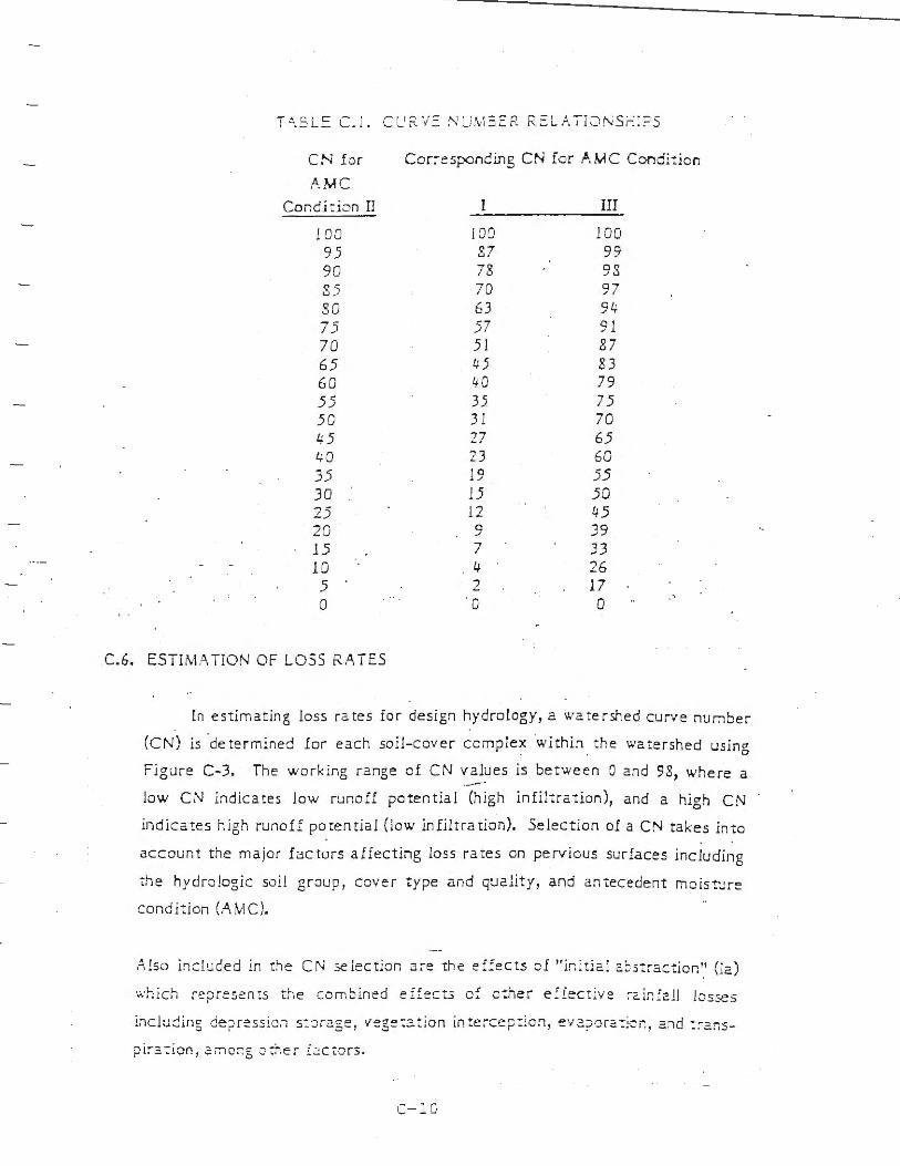
C.6. ESTiMATiON OF LOSS R.A. TES
[n es1:imating loss rates for design hydro logy, a watershed curve number
(CN) is determined Ior each soil- cover complex ·within the watershed using
Figure C- 3. The work ing range of CN values is between O and 98 , where a ·--·
low CN indicates low runoff potential (high in filtration), and a high CN
indicates high runo ff potential (lo w infiltra tion). Selection of a CN takes into
account the major factors aiiecting Joss rates on perv ious surfaces including
the hydrologic soil group, cover t ype a nd qu2lity, and antecedent moisture
condi:ion (AMC).
/\!so included in the CN seiec tion a:-e 1:he e:fects o£ " initi2.l 2. ::;s:ract ior. " (12 )
wh ich represents the combined e ifects cf ether e: fectiv e :-c.ir: Ic.11 losses
inclucing de?ression s : ::i r2.ge, vege:z: ion in : ercep : ion, e v 2.?0r: -:icr:, 2.:id : :-2.:1s
pir.:. : ion , 2.mcr;g o ~r.er £2ctors.
C- j_O
Cu:-1~ (!) Nur.i:>e~! c: Hvdroiot.ic Sc i..l-Cove~ D~ole:xes Fo. .Pevi~ .-".:e.u-AMC rr 1
QLJL!J -:.y oi L Y' ii r, ,.,....,.... ~
1
I i
I
C::v~:- 7 :1~ ( J )
N.~ T"..J.R . .t. !... C O\f~RS -
B.&.:7en (R ock!a.-id, e,::>de::i a'"lc g:-a.::jed 11nd)
Chapa ~7al , Broadlea: (Man.::xi i:a, cea:1othu~ and '-Crub cal<)
Chaparral , Narrowl eaf ( Cha;ni.5e and redsha.."'lk)
Gra-5.3, Annual or Pe:-enn ia1
Meadows or Cjene;a.s (Are!.5 wi1h ~asona.lly high wuer table, princjpa1 vegeu tioo is $od .forming grus)
Open Brush (Soft wood shrub5 - buckwheat, sage, etc.)
"ll' oodland ( Con ii erous or broad!eAf trees predomi~ te. Ca:,opy density Ls at least 5{) percent.)
Woodland, Grus (Coniierous or broadleaf trees with canopy density from 20 to 30 percent)
URBAN COVERS -
Residential or Commercial La11d5eaping (Lawn, shrubs, etc.)
Turi (lrr iga ted and mowed gra!.5)
AGR!CUL T"JRAL COVERS -
fallow (Land plowed b1.;t net tilied 0< ~dee)
-·
SAN 8ERNARD1NO COUNTY
HYDRO- OGY MANUAL I r _ i:::
.. 1,1 '-' • ~~ J C ~ v •- r 7 ) 1· A j ~ / C f .< , - -· \ - . . - . .,
P:x::>r Fair Good
Poot' Fair
Poor Fair Good
Poor F&lr Good
Poot' F~r Good
Poor Fair Good
Poor Fair Good
Good
Poor Fair Good
J -1 f I , I
I 7 _! I !6 i I - J I~ I., I -. I --·- · I
5) t.-0 '1: 1 .., ~
71
-'-'
70 6) 57
ZJ I !J 75 I ! 1 71 7!
!2 I i~ I 91 72 !1 !6
6 7 l 7 ! I 86 I 8 9 50 69 79 81, 3! 61 74 &o
63 77 S5 U 3 l 70 !O &4 30 5! 7 I 7!
62 76 t4 !J q.6 615 n &J 41 6J 75 11
4" l 66 I i7 I !J 36 60 73 79
2.3 35 70 77
57 I 73 I !2 I !-6 44 65 77 32 33 5! 72 79
32 I 56 I 69 I 7 3
58 I 74 4/J 63 33 .5!
i7 !o
!J I !7 77 !1 72 79
,..---,... -~ -) 194
I
CURVE NJW!ERS FOR
l
I I
F£ RY ,ct.~ AAE.A..S i J
Fii;ur'9 C-3 (r of 2)
, I f
-- 1.
I
I I ·. I
I I
Curve (I) Numbers of Hycirolo,tic Soll-COver Com2le:es Foe- Pr.vious Areas-AMC Ii
I Quality_~ Sell Ge-oup Cover Type (3) I Cover U J A I 5 I C I D I
AGRICULTURAL COVERS (Continued)
Legumes, Close Seeded Poor " 77 a, :, (AlfaU&, sw~tclover, timothy, etc.) Good '' 72 u 1.5
Orchards, Evergreen Poor 57 73 !2 &6 (Citrus, avocados, etc.) Fair tJ.• 6.5 n 12
Good 33 .5& 72 79
Pasture, Dryland Poor 6! 79 !6 g9 (Annual grll>es) Fair 49 69 79 !4
Good )9 61 74 go
Pasture, Irrigated Poor .5& .,,. !3 u (Legumes and perennial grass) Fair " 6.5 n !2
Good )) ,a 72 79
Row Crops Poor 72 I 1 ~ 91 (Field c rops - tomatoes, sugar beets, etc.) Good 67 7& u 19
Small grain ?cor '' 76 14 u (Wheat, oats, barley, etc.) Good ,.3 1, 13 &7
Notes:
1.
2.
3.
.
All curve numbers are for Antecedent Moisture Conditio·n (AMC) ti.
Quality of cov er definitions:
Poor-Heavi ly grazed, regularly burned areas, or areas of high bum potentia l. Less than 50 percent of the ground surface is protected by plant cover or brush and tree canopy.
Fair-Moderate cover with 50 percent to 7'5 percent of the ground surface pro tected.
Good- Heavy o r dense cover with more than 75 percent of the ground surface protected.
See Figure C-2 for de fin it ion of cover types.
VFW~ ~~n:r,c~nU!!~o COUNTY HYDROLOGY MANUAL
C- 7
I
Uf;fE NIJMBERS fOR
PE~VKJUS ARUS
Figure C-3 (2 of 2)
n I
I-'
w
n I
(..JT
I (/J --< ) .')• CJ :z: :-u () (l) r 0 f"TI G) '.:{) -< :z~ ~
) » ::u ) > CJ z ~-~
C :-z. ) :>- 0 ,-
0 C> C: :z.: -ltt -(
(j)
::..( J C)
::u ) > (n Ill ..... 1- ,L • - .., , N .Y' ) :,.
- -t , ·- .,:i. 0 r - I 2'. I T Ul :u O .:r: C C "11 Z .:.u UJ 0
-,, UI - q -- 1
0 Al ~
6 7
24 - 110UR STORM RA INFALL , P ( INCH )
e tu II
·--__._ ___ ·---------------- ------=----------------------- - ---

·r
I (Jr) -< ):> 0 ... .,, ~
mi;; ....
no G n1 G) JO -< :z
z 1.0 • 1 -
~ ).> J"> 7J() '":,,, CJ ... _ C l> -y, ..... r- ()
r --i .9 :n }> · · t 0 z .B :::o
() ()
}J - t n 1 .7
<= =~ -;
"Tl 0 :n
.6 ll w<
( ) rTJ :o
t 1~
U1
<. .5
0 C (f)
1~ .4 :u ·u P1
P\ z (f)
~} -q ~ ..... : n r ·
).:,
U)
.3 • I
-0 U) 0 - I
C: :u 0
(/) ):.,, C - i :XJ l:• ..... :o 0 fll :z Pl
=> .2 ()
:r 0. v , ', .I -:::,-0 z ) .!• :u C (./)
i': ).:,,
lU <..: - I -n
r11 fll rr1
'° ~ ;u C .., U ) U) "'Tl w 0 C ()
(/) .:u I
C .,
AM C -II SCS CURVE NUMBER (CN )
Cfl

I I I I
I I
I l I I
I I I
---_:..- .,.- -------~---- -:- -
-.... --;.-
.-- .-:,
-.... . :--:.7'1 _: .: , --
' I .: -d
: -'J
'. . ' . - :! I
:: ...1r• --,_ --~-- - ----· .,.- · ,·:-· .... 1 ·
!I .. ·, I
' .f .. ~ _/}.
t_··_ '
ijl!.~
I '
I
~ --- -"-
-~-----. -· .-
. 11 . - - - ·
;; ·
:==--=:-.:· ----- -
~v - 1
--1 , ,.. .1. · ,,,.;,,
c:: .~ 11 ("' .._, •.J 1L ...:::
-~ ~- i 11:_: · · · r-- -- - · - ' • I tV :. :) I - C
··•· ...... _ ~-· ·.
;--··- --·:..: ·- ~:.t __ ~:,.;-.. ~
,: :::: ,-1 , \.: I • L ' l .: ;-'
·'' :::,~ \ . . -. .___ ,---,.
I I I
I i I I
I

1.
I 11 'T
a
1 1
- ~ - + -~.:..~·- ---::--:-,1 - 12.0 ___ ___:__- ~
- . -- ...- ·- --··.,~-J_ :·
L .=.lL~~ -;;;· ··~·· ·==· ~'·::::··"·=···~f:;:;;: 1 ·, _, ,---;·J:.-]_"'-"''"'s..:..:.···~·:'o_.~::..:..-- !_!('_!._I -1..i ':_' -,--j_+!_!._--J_- ~ ~~:,..:_:,_~ "'i'-'--b,;::-:-~~~*-~ ~
~~;~ l - _{J.,, < -... . ~.
/
I i
\
I _/
( \
· ( -\ ..
JOE
\ •l•::;\
~ . (/ ~ / ·- -
• ;J - ;:: : ',V ' ,
COUNT'r'
R i::DUC ED OR AvV! NG :::C..:..L ::: 1" = 4 VdL::: :3
P. 2 E
...'.... .: 4 "'JO
'.5(:Uv:- 1~3
X 4 - }C'() ':' ~ .~R 2"+ -,cuR -µ S£C ) N J '.:. J.C., 'tO A . .,.J,,. ff~\ S :. , ;'97 !

J
I
.I
1 . '
- _,
T I S
\~::sf- - . -~--
- -_,,/
·""
,· _,,.
COUNTY
u.a-
DF. ; Wl~~~G I = .,, ... • . ... .... I
"-t It'l l -- - .
!....-----------SC.:'.L~ I
f;C:OUCED
:,;95~9: (...-3.0 ,SCL :~J ~t·::Pt7l7tC-flit · IMC:--£ :;)
I..Z RI E
3.0
cco.rr T
VALLEY .A.~U ::::.--:·11t:T.i.L5
X z - ~ 'f E . .!.R 2 4 H<:CR Uj.[lJ .;• .J..~~r~ .:., M l
I

APPENDIX C
ASTM D 1557-91

n-, ft IM Dps :a,.. - -1· "n· ,.. "::::- o-~ D )J) - ·-""" .., .. - . ~- - - (:;aaoprovec 1998_\
A.MEMl:..a.r,; ~::::c,=n· ==-oF T:=7°ll'JCi .\N:' M..:.1: n,.o.:..: .:;,:. :......· : ..... "':,,.'.'.; C;., 'ft~:: ·: -,,..~-,:-,:-='="''=r; c.,e : I\!:!:'
F,eorintec rrom me Annual 6001. o: A::T"-'. S:una.1,ua: C.Jpvn9n1 ~ 3 1 r/
Test Method tor Laboratc:irv Comsaction Cha:-acterist ics o f Soil Us ina Modifier: Efto~t (56:000 ft-Ibf/ft3 (2,700 kN-m/m 3
) )1
- ·
Tnh: sum.ian! 1•; 1s-.uaJ un1..l.:r lh: ii:c: d uc,;1pa1ior D !5~"'.' : th:: numcn:- mtm::t.liat::-ly /'o11owrn;; th: d:::!a1,:.-"!lat1ur muu;:i.r::. Lh~ v: a: c· ong,nal adopuon or. 1r. tn: :..i·;~ of r:vi"1or .. th~ y::ar or l.::ist r:vis1on. A :iumocr 1r. par:nth: :.e:. md1c.:.itc•, the y=:.ir or 1a~1 r::.ippr~••;iL .-.:... ,;up,:ncnp1 .!p\"'ilon I ! , 1:101::m: , Jn cduonaJ =h..!.'1~:: .,;me:: the li.Js-1 r:n !a10r: or r:.ippro~·:il.
l. Scope
1.1 Tnis te,L mechod cov::r, laborarory compacuon procedures usc::d LO derermine the relationship between w;iter comenc md dry unit weight of soils icomp:i:tioo :urve) compa:t=d in :! .:L or 6-in. ( 101 .6 or 152 . ..! mm) d::tmeLer mold with a 10-lbf. 1-'h.5-NJ r:tmmer dropped irom a heigh: of 18 in. (457 mm) producing a compacc1ve di'or, of 56,000 ft-lbf/fr (2,700 J.::"1-m/m:; )_
Norr 1-Soi!s and soi!-a.,;g:r.,gat: m,xrures .;hould be rep.rd~d :t<
oacur:il occurring fine:- or coar:;~-graincd .::.oil~ or compo:dl!!.'- a:- mi.itur~.~ of narurJ! soil5, or nu.:ccur~:: of nncurJ! und proc:::s~c:d ~oils or aggr: g:.He~ .such 1; ;ill, gnv:I. or cru,hed rock.
Norr :'.-The eguipmenc :ind proc:dur:s ar~ tho sam: ~; prupo,:d by
the l!.S Corp., of Engineer; in 1945. Tb, rnodiiied :lfon ce.;r (m: 3.2.::?) is sometim: s r:ferr::d co as the ?vlodified ?roctor Compacci on Te.st.
J .2 This rest method applies only to soils thaL have 30 % or less by weigh, of theu p.i.rticles retained on t.he :Jt'.i -in. (19.0-mm ) sieve.
.NorE J-For r:tation.i;hip~ bctwe::n unit l,\·:ight> and wat:: conc:nt::; of . soil.< w11h JO"< or le,; by weigh: c1: rrwt:rial re t:l in~d on the h-in. (19.0-mm) si=ve co unit wei~t.., :ind wa1:r conten'., ofrhe fr:iction pa.ssinf i.h, J/,- ir.. (19.0-mm) si~v.:. ; ,:e ? r4cLic: D ~7 JS
1.3 Three :i..l,emati ve proc::-dur:s are provided. The procedure u;ed shall be as indii.::i.ced in the specific:ition for che rm.teri<I bting Lesr:ed. If no procedun is specified, the choice should be b:i.1:::d on the m1Lerial gr:1dation.
l .3. l Procedure A: 1.3.l.1 Mold- ·' -in. (10!.6-mm) di:i.merer. 1.3. l.2 Marerial- Prissiog No. 4 (4.75-mrn) sieve. 1.3. J.3 Layers- Five. l.3.1.4 Blows per layer-25. l .3. l.5 Use- ,vfay be i.:sed if ~O % or Jess by weighc of the
m:iLerial is ret:iined on the ;'lo. 4 (4.7 5-mm) sieve. l J. l .6 Other Use- If this procedure is not specified, mate
rials c.h:n meet these gr:1dmion requ iremems may be reseed using Procedures B or C.
1.3.2 Procedure B:
1 Thb 1::st m::,hoct i,: umJ:r the Jurisdiction of ASThl Commirr== D- IS an Soil :1rn1 Rack ~nci is rhr:: dir.:c:1 r=-:-;pon.-.ihiliry or Sutx:ommitL:: 018.0.1. ou T::::'tlur:. Pla!ilic1C) JJ1rl D: m11_v CnarJ:1c:maics of Soil::.
Cwr.:nl tUl(JOn aporoved Su,•. 18. 1991. Publishtd Janua.ry J09}. OnJ,;in:illy pubh..;hcd a.~ D 15ji - 5K. l.1..;1 p~v 1ou, :di11on O 1.55'; - 7S , !090LE1
1.3.2. l ,'v!old-·-1 in. ( I Ol.6- mm J diil.!Deter. l.3 .2.2 Marerial-P:i.ssrng 3;,.-in . (0 . .5-mmJ s1:ve . 1.3.:?..3 Layers- Five. l .3.:?. . .1 Blows per layer- -, "i. 1.3.2 . .5 Use- SbaU he used if more t.han 20 'ii- by weigh t of
Lhe material is retain~d on the N o. 4 (.:!.. 75-mm ) si:ve :ind 20 'io or less by weight of the :nacerial is maincd on the :i-~-i.n. (9 . .5-mm_l sieve.
1.3.2.6 Ocher Use- If this procedure is nm specified, materials rhar m~el i.h~st gradation r::qui.r:::mcms m.1y be Lested using Pm::edure C.
] .3.3 Procedure C: J.3.3. 1 Mold-6-in. (15:?..,Lmm i diameter. l.3.3.'.2 Material- Passing ~,'.i-in. (19.0-mm) si~ve. l .3 .3 .3 Ln.ve rs- Five. 1.3.3.4 J:Jlow.i pu layer-56. 1.3 .3 . .5 Use- Shall be used if more t.h:in 20 % by weight of
the material is retained on Lhc ~'i!-in. (9 .53-mm) sieve :ind less i:.han 30 S'"o by w::ighr of !.he rn:i.terial is retained on the 3/,-in . ( J 9. 0-mm) sieve .
1.3.4 The 6-in. (152.4-mmJ d~a.ueter mold shaU nor be used with Procedure A or B.
Norr 4---R: .sulL, hJv: been found ro VaJ:' .s lighcly when :.i m:.iccria.l i, ce,ted al the ;ame cornpunivc dfor. in Liifi:r:nc size mold,.
l.4 If !.he test spe: i.rnen contains more than 5 n by weifht oversi~e fraction ( coarse fr:i:Lion) .ind ::he m:1t~rial will nor be included ia the test, corrections m ust be made to the unit weight :ind w:i.ter concenc of the test specimen or co the Jppropriate field in place density tesc specimen using Pr.:ictice D47!8.
1.5 This resr method will gener:illy produce well defined mJximum dry unit weighc for non-free draining soils. If t:his rest method is used for free draining soils the m:1.ximum unil weighr may nor be well deftned, a.nd c:m be less ch::rn obtained using Test .~tee.hods D 4:?.53.
1.6 The values in inch-pound units J.re to be regarded a.s i:.he st:i.ndard. The values St.ltc:d in SI units are provided for informaLion only.
1.6.1 In the ::ngineering profession it is rnstom:1..-y practice co use, in1:::rchangeably, units represenc.ing both mass :ind force, unles~ dynamic Cillculations (F = Mu) are involved. This implicitly combines two sep:J.r:i.te systems of unilS, that is. the absolute system J.J1d the gravirner..--ic sy~L::m. [c is scientific:iUy

ii~ ~ C· -,::::•1u1,. · • ~~ ,
:..:~c:.; :::._:-..!~:= :,:, C1 r:1 =}i:l ·· ~o-:~· ! 11: ~ ~r ~ .V [ $::r~-;11:: :::ys t:::;r.t! u·itiun ; s~;I~ s::mcrd T n:, Le:;: m;:,hc,d h:i.;; be::r- wriw:n usin;:-1n::: ri -round units f. fTJ v1 m::uic s:-•st::m, where the pound ( lof, r::ore::!n'.:; 2 L,r.1 · o( for:c. Th~ use ot ::i::ss (lbm .i i, fo, :on, cmc:n:~ O' uni c;· .inc '.. no: 1nr::ndec m conve~ me us~ 1s sc1c.:n;11i c:.!lly corr!:::. Conv::~sicn:, a.r:: gi veo in the: SI sym:m in :icord:in:~ 1\'llh P~J:ti:::~ ::: 3SO. Th::: use oC ba.1:inc::~ or s.::i.l::: :; r:::: ord1nf pou 11c.!s ni" m;m (lorn) or c:h:: re:ordi.n; of densiI:v in Jom/f:' shouiJ no: oe r::;::irded :G nonconforman::: with tots st:inc!:1rd.
1.7 Thi.; .itandarc! docs /Lil l p11rpor1 10 uddreS.i all r~( the .wf e·y concem 5, (f" any. associaced wi1h ics use. !1 is 1he re.r11onsibil1ry o/ 1h,· mer r.,j 1/ziJ swndi.lrd /0 e.rrablish appm· priale .rnfc/1' ar.d hea/1h pracriccs and dc!ermine c!U? applica
biiiry u( regulworv l1rni1arirms prior 10 we.
:!. Rcfen;nced Docu menG
'.: .! ASTM Srandard;: Cl ~7 Tes: .'vl:::thod for Spe:ific Gravity and Absorplion of
(oJ.rse . .o.ggrcgace= C 136 .\,feti,od for Si~ve Analysis of Fine and Coarse
A_ggregat::s: D 422 1\tfelhod for Pmi:le Size Amlysis of Soils3
D 653 Tenninoloe:v Re!atim: co Soil, Rock. and Cont::iincd FluidsJ - · -
D 698 Test Method for Labor.iwry Compac,ion Cn:ir::icteri;tics of Soil Using Sw.nda.rd Effor.: [ 12,400 ft -lbf/f~ (600 k."\-mJ/rn3)f
D S5~ Tes: .\J::thod for Spe::iJic Gr:ivi:y o[ Soi.ls' D 216.S Test J\.lethods for Calibration of Laboratory
~1e::h:uiic:tl-R:unmcr Soil Compa::tor.? D 2~ I ci T::s, Melhod for Laboratory Determination of Water
(\foisture) Conteni of Soil, Rock and Soil Aggregate :.Iixrure,?
D 2..!.S7 Tes: Me:hod for 0:lSsificacion of Soils for Engineering Purposes3
D 2"-SS Pr:ictice for De5::ription and Jdemification of Soi.ls (Visu:.tl-:,,ianual ?rocedure_13
D 4220 Practices for Preser1·ing and Tr.1I1sporting Soil
S:i.mplcs3
D +253 Test :Vfc!.hods for ;\faximum Index Deosiry of Soi.ls Using a Vibr:icory T:ible3
D 471 S Practice for Correction of Unit \Veight and Water Conccnc for Soils Contaioing Ovc::rsize P:irticles 3
D +753 Spccific:nion for Evalua:ing, Selecting and Specifving Balances ::ind Sc:1ks For Use in Soil and Rock T.:sting3 •
E I Spec:i.lic::itian for AST:VI Tncm1ometers·1
E 11 Specilic:ition for Wire-Cloth Sieves for Trning Purpose~"
E:; 19 Practice ior the Evllu:iciun o[ Singlt:-P:m '.\frch:inic:il E:il:inces4
E 3SO Practice for Use of the SI Intemationai System of Unils (SI_l~
:: ...l.nn,..w.' 3,ml... 11,-A~TM S1rinJnr.d:,. Vol IJJ .O:. ; Anriz,!J/ Soul.. ,11-As;*'.\f Swr:Ju,-d.\. Vol BJ OfL 4 :\1111LJ11! 8110J.. ,i.-tS7)1' S1un:.iLirris. Vol iJ.(lJ..
:!
::. Tc:-minolog:
~-1 D::1111) ru111.,- Sr; -.: T~:-=unnlt •.:;: [, o5:? io: f!!ncral ddini~1nn.: .
[ )c/inuinn.: ~~ ~!! 1"111: Sn:·:":·11:· IP Tit i..t: Scan.lard: ::' .: .1 moc·,ri::~ ~,'f:-w.- Lhc t:.:~r:~ for :he- _-ir UOO f: -lbf/f::,
.: ,oc 1:<-m1r..::, co?:ip;i:.:,iv:- ~ffor. appli::d oy tht: cquipmco: :me procedur:::c o: du:. t::s:.
: .:.::. nloC(Ji~c' n1c._:.··inuu1 d~ U.'!l." w~igh .'. -..u,nc, r i'1Df/f:."in:..~,' m·\1-t.h::: ma:;imum v::Ju~ a~ it ncd n_1 th:'. cor.ip:i::uon c:urvt fo r :.1 ::ompac'.ion t:::st usinf mod i.li ed elfon.
3.2.3 mnc!.£fied npri111w11 wa1cr crm1eru. 11., (';'r.J- r.he wau:r conten: a: whi:r. !.he soil cm be comp:icted w Lh :- m~::imum d:-:- unit wcifht usinf: rnod:Iied compa:u ve t:ITorL
::.2 .4 01•ersi:E _rrauio1! (coarse f raccinn ), P<: (Soc 1--i.he portion of coca! sample noc used in periorrning the compa::tion cesc; it may be the portion of tot.J I ~:irnplc re,ained on the No. 4 (J.74-mm). J, i< -in. (9 . .5-mm ), or 3/J·l!l. ( 19.0-mmJ sieve.
3.2.5 ccs: fractior. {finer f ra.CW)I! ). PF ('7r )- the portion of Lhe mt::i.l sample used in p~rfomung the cornp::i::tion test; i( may be fra:tion p:?Ssi.ng the No. 4 (4.75-mmJ sieve in Proceduse A, minus ~·11-in. (9.5-mml sieve in Procedure B, or minus 3/, -in. ( 19.0-mm) sieve in :Orocedur: C.
./. Summa r )' o/' Test (\fethod
4. l A soil a, a ,elected water cornea: is pl::iced i.n five lnyers into a mold of given dimeosions, wi th ea::h l::iyer compam::d by 2.5 or 56 blows of a 10- li::>f (44.5-!-,r:1 rammer dropped from a ciisrJnce oi 18-in. (457-mm), subjcccing lhe soil iO a coca! cor.1pa::tive e(fon of abouc 56 000 ft- lbf/ fi (2700 k:''1-m/m3J. The resulcing dry unit weigh t is det~m1ine-d. Tne procedure is repc:ited for.!. sufficient number of 1vater concems to esLJblish :; relationship between !.he dry unit we ighi and r.ne water cont:::nt for the: soi.J. This dat::., when planed, represent a curvilineir relationship l:nawn as the compaction curve. Th::: values of optimum water content and modified maximum dry unit weight are dclerwi.ned irom the :omp.iction curve.
5. Signi.iicance and Cse
5.1 Soil plac:::d as eoginc::ring iiU (:::mb:.10!:mencs, foundation pads, road ba.s::s) is compacted w a dense state to obtain satisfoccory engi.nce:ing properties suc.:h a.s, she:ir strength, compressibility, or permeability .. -'\.lso, foundation soils :ire often compacccd lo improve lheir cngi.m:ering properties. Laboratory compaction tests provide the bJ.Sis for determining the perc:::nr compaction and water content ne::dcd to achieve the required enginc;c:ring propenics, and for cont.ro I ling construction co assure !.hat the n:guircd compact.ion and water contents are achieved.
5.2 During des ign of an engineered fill , shc::u-. consolidaLion, permeability, or other tests require prepar.1tion of test spc::imt.:ns by comp~cting at some 11.·ater conten t to some unit wcighL It is c.:ommon practice to lirs, delermine the optimum water content ( wJ and maximum dry uni t weigh t ( -Yum,..- ) by rnc::tlls oi a compacLion cesL Test specimens arc compactc:d :.lt
a sdccted w:m:r comenl ( w ), either wet or dry of optimum (w,,) <'rat opLimLim (w,.J. :ind :u ~ seltcted dry uni t wci::;ht rcbted Lo :i pcrcc:t1:Jgc of m:i::imum dry wi it we:ghl 1 --Yu,.,,,J The s~b:Li::in of w:i.tcr content (w) . either wet or dry o[ opLimum (w.,i or :it optir:wm 111·.,_! a nJ ,he: dry unit wet!_'.hl ('furr.a• -l m:iy be

~ITT~ c ; ss:-_ ......... -... ... .. u _-. ._ U ~II• I' '"-•·'- --· ---:,· ~ ..... .. ~~ :-'..!.!~ ~ : •:if ,.-:11u~.- ::::.!'- De ~ a, actio, :.r ._,,~ tw!• ~ , u.,,c..
: ::';'" : .:!.' !'" :-_: :- ,-:--;:: ==, -=-= !fl\':~;:l ~.:!h.:.:: t[ u::::;t::1::1.1n:.: ~n:.: n:::::::-::;;1-- p=:-:..:=;E .Jf .:r, n1n:1::uor .. 0 11 ~ o~W'T\Ou-. ::-vv:-uo, .. Ok uuo·
,,.., i),C_ ,..'= Da•r , itr I'\ unn-.c< nro,or.
,;. A .. pc::t:-.J.lU:'
c .. ,\·!:iL' _.i_~·.;:::•1!.:-/.' -Th~ :~1::,Jd· 3h:J..!l i:,e- c:;hndri.:Jl ir. sb:ioc:. madt or ngid :net.1) a.m: oc: ":Lnin Li-i= .::ap:i:i ,:· and dtm::ns101E iodi~JLed u- C:. J. J o· ci.l.2 ::u1d .rig.! and Fi; . .: . 7nc: 1v:ill::: of tht" mold mu:, be sul1d, spin. o, tJpc:r:::d. Tn c: ··spii t" type, rr.ay consis, of [\\'O h:ill·-round se::uons, m a se:::uon or pipe split along one demem, which c:in bi.: 5e:::urely Joded togelher to form J cylinde, mt::::ting the require men cs of chis :;c:::tmn. Tne ··,.ipcred" ryp~ shall Jn internal dt:imerer raper th:it i.~ uni.form anc! nm more lhan 0.200 in .It I Jo.-:- r:imi :n l of mold h:: igh t. EJ:::h mold shall hJve a base place Jnd :in ::.s:.tension coll:ir assembly, oath made or rigid metal :ind conmu:::ted so th:y cJI1 o:: sc:::urel_1· ar .. Jched and easily deta:: h'.:d from che mold. Tbe extension collar :issembly shall have :i heigh: exc::ndi.ng aoove the rap of lhe mold of J.! le..!.st 2.0 i.n. (50.S mm) which may include ::in upper section that lb.res ou: to form 2 funnel provided there is at le1s: a 0. 75-in. ( ! 9.0-mm) st.night cylindrical section beneath it. Tne extension collar shall align wich che insi de of the mold. Tne bonom of the b~sc plute and bouom of iJJ::. ccnt.r..illy recessed a.reo. cha.t ac:::ept, the cylindri::il mold sh:ill be planar.
6. 1.1 Mold, 4 in.- P... mold h1ving a 4.000 = 0.016-in. (]OJ .6 = 0.4-mm) avera.ge inside dia.mete r, a height of .;.5S-+ = 0.0 IS in. ( ! 16.4 = 0.5 nun) and a volume of 0.0333 ::: 0.0005 ft; (94-l- = 1.1 cm3
). A mold a.:;;:mbly h:1\·i.ng the mintmum required fearJ.res i:; shown in Fif. 1.
6.1.'.: Muld, 6 in. - A mold having a 6.000::::::: 0.026-in. (152.4::: 0.7-mm) :J\'er.i.gc inside di;:imcrer, a height of .::.58..! = 0.0 IS in. ( 116.4 = 0.5 mm). and a volume of 0.075 = 0.0009 f:3 (2 12..1 = 25 cm\ A mold J3i!mbJ_v ha1·inf die minimum required feature, i..l shown in Fig. '.?..
6.2 Rwnm!!r- A ra..rnme r, either m:111ually operared as desr.:ribed former in 6.2 . l or mc:h:ini::a.lly oper ated a.s described in 6.2.2. The rc.mmer shJ.U fa.II free Ly through :i distJ.nce of 1 S ::: 0 .05 io. (45 7.2 = 1.6 mm) from t.he surface of che specimen. Toe mass of the rJ.mmer shJ.!l be 10 = 0.02 lbm (.:: .54 ::: 0.01 kg), except rhac the mass of che mech:mic:il r:1r:-1mers may be a.djusted as des cribed in Test :\Jechods D 216S (see Nore 5). Th~ S[;'i.k.ing face of Lrie ra.rnmer shall be pl:ina.r and circular, except as nmed in 6.2.2. l. with a dia.rneter when new of 2.000
H M ootlcr. lo thl hJ,11 I~ "'-c!, I 2 Jj:' II: J/ "' ni.,cj l'N7r' b,I .......:'. n,.." oc. .,. ~/\~ CIIJofWl.t\d.11)1",, 1.tM c:>lor ""°'f tM "'-'Cl OO•n wit,\ ~ l icJ U• C! 0,,,11~ an oc::r"Ni LA u,... =,ol,o1' ~ ai p,1" WI the makl..
at::Ocr-:j :.r I,,_ c.ni4,r ~ ll :i,&r I." W. ~ -
/ ;,-.,
,.st·'//~ ./ / / ~ . '- I ' L--. . // /~ ...... "\ . ! / ' ,;:- . - - · -~ / ! '> '-. ~· I ' ::. •
,,/~ "' ' - ~ - . .. : ... " ""- !;, r~"'- ::. ,~ "Ti1t1 : - .o;r -rw-
\. . ~_,..__- - - ' , t. ~; er , I / - ---- -- --·- 'I[
, ~ /L ,I cur .. ' j .. - ": ' : .. ~ ;:_i_, rnJd.. .,,LJ L. , ... ~
/-9x1J/;__Jtrt-J i : ~0,1 --1 IQ
" '-"'
see '";"ao,e ~ rcr me1n: eauwalenlS
t, ' T!llit 11 ,;:- ' 'j'l
\ _ C.137=-
C,,£\IAnc-.i
l Ll-cr, o;::1 =! -..i a • it
FIG. 2 Cylindri:::al Mol d, 6.0-in.
= 0.005 in. (50.SO = 0.13 mm) . Tn::: r:l.!11!71t:r shall be r~pbced ii chc sui.king face be:::omes worn o. bdlied to the extent Lha, the dia.metcr ex:eeds 2.000 = 0.01 in. (50.SO = 0.:25 mm).
Non: 5-h i; a common and acc:p1.ahl: pr:.i:cic:: i r. !he inch-pound 5ysr:m w aHume thac ch: ma.:;~ of th: ramm::r i!- equuJ 1u it.:; ma..,:;_:; d~tenninc:~ u;inf cith:::r :1 kik,gr:im or pound b..ib.nc:.: i.ln t.! . !bf i~ i:qu:.d Lo ! lbm or 0 . ..::30 kg or ! .\/ i, equ:il lCl o. ::::!.J.S lbm or 0.1020 J:g.
6.:2. I 1vlwwa! Rcwim!?r- Tne r::i:rnner shall oe equipped wich a guide sleeve Lh:1: has su fii:ient cle::ir;mee lhv.t I.he free fall of [he ra.r:uner shaft and he:id is not remicred. T ne guide sieeve shall ha.ve a, k:is: four venc ho le~ J~ c.1: h end (eigh, holes ro,;i]J loc:itc::d wirh cemers 3/., = 1/,,; in. (19.0 = 1.6 nun) from each end Jnd spaced 90° apac. The rninimu:n diamer::r oi rhe ven l hoks shJl1 be 31R in. (9.5 mm). Addicion;:i! hol::s or sloes may be incorpomed in the guide :;leeve.
6. 2.'.:. i"•lech:mica! Rcmzmer-C ir:·ular F.:zcc- Tn= ri.umer shv.11 aper.He mcch:inic:i.lly ir. su:::h a manner ;i.s ro provide uniform and :::omplete co1•erwgc of the specimen surface. There sh:il.l be:: O.JO = 0.0]-in. (:2 .5 = O.S-mm ) ckv.rJnce betwe:;n tbe r:i.;11mer :ind the inside surface or tbe mold J[ i[s smallest d:ameter. Tne mechanica.1 r:i.mmcr shv.ll o eer the :a.libr.i.tion r!quiremenc.s of Tes, Methods D 2168. Tne me:banicJJ rJm.mer sh:ill be equipped with a posiriv~ me:::hanicJl means ro suppon: !..he rar:,mer when not in operation.
6.2.2.1 Mechanical Rammer-Sector Face-When used with the 6.0-in. ( 152.4-rnm) mold, a sector face ra.mmer may be used in pbce oft.he:: circular foce r:imc.1er. The specimen cont:1ct face sh:ill h.i vc:: the sh:ipe of .i sec Lor of a circle o[ r:idius cqua.l to 2.90 = 0.02 in. (73.i = 0.5 mm). Tne rJJnmcr shall oper:iw in such a ma.nner t.ha[ the vcm:x of the se:cor is posicioned aL the cenrer of the spc::ci.men.
6J Sample £,:1ruder (optional)-.:... jack, frame o r or.her device adapt:::d for the: purpose: of e:zLruding comp:icccd sper.:imrns from t.h~ mold.
,..,,., C,.:.-Y4 7IC>,1
see ~aole :! for mern: eou,val!!nts
FiG. 1 Cylindrical Mold, 4.0-in.
3
6.4 Bal!.!nc!-A. class G!'5 b.iJJncc meeting rhe requirements of Spc:6iication D .. r;5:; ior a b;.ib.nc~ of l-g rcadabJity.
b.5 Dr:ing 01·e11-Thc:rmost:.1tic:11!y controlkd, prd::rJh!y of ::i for~cd-dr:ifl r:'iJc and :::ipaolc of u::i.imaini;ig a uniform tcmpcr.irure of :JO = 9°F l l JO::: 5~CJ rhroughouc chc: drying ch:ir:,ber.
6.6 Sirc.i~htdgc-.::... stiff mcc::.d ~tr:1ighLrdgr.: of ::.ny convenient kngL, :Jut not less Jiar. IO :n. 125-+ ;n_,JJ. The LOL:il Ie ng ch

~ITT~ D1557
,:.·- '...J-::: ~~!:--2.;:-;:.:.:::~ :: ~:~ .'..!.! 0:- n1:1rnLn··r· .;r; :1 1 :T h: tc., :.. [ol::~:.inc~ of
= C.J'..'.: :.r. · = ::;. 1 r.u-:1 , : n: s:::-:i.;::,111 _!; ::dgt:' sn:i.U oe ::>t"velcd ii soi l m d1..::1t:: ~:i: r~~.JI!: ~·~I. D~: ~.!.H.:r.,.; l,.. ~:· J. t· .:-:-:•1 :-1f_. t.!!;e :h:: mc!s pr::r: :.!r--uur . .71:.;tn0t. 1. ,:-~ i C.:
i. i: thd.:e~ th:i.n :., in. (::' mr:u c - 5:cvc:- ;--in 1· ! a.0-G:.1 ,. ; ·;-Lr. 10_:,-r:1:n ) :ind :'lo. 4
, ~. - .:-- ::1:.,J. : '.)nfo r:nw~ tr the r~qLur~menL: of SpE:i.ficauon E 11
I (J.! ·~-: ?-::p.Y~ Ln= soiJ :;~c:.: i.r:1:::i. t'.:, i t= .;~u:=· L:1 .:i =:~rd.1.Ilc~ with I C.:' 1ore i::rr::d or v:irh JC.: .
JL1.: ,i1r11.:: · Pr~,.'?C."i:UUH: 1\·l !.' .'I ZP:.. ;;1 ,i-::..:· :._·····~·d-V\'i:hDu: pre
v1ou"I: ar:'ing Lile: samnl: . oass i. chrou;r.: ~~c. - 1.'.l .- 5-ITl..'!l J, ~-, -in. 19.5-mrn 1, o~ 3·-·tn. ( JS1.C:-mm , , 1:.: l'e, a~r,~ndi ng on dJ:: pro:ed urt , .-'-.. B, or C , ::i::mf used D::t:::-mi.n: ui~ w:ile: :oncem of tllt process:!d 50i.J.
c,.S ,~h::!llg 7i1o!s- Mis:::IJ:mwus tool!, suc:h :is m~-u ng pan. sroor,. crc, w::1. so:m1l~ sprJ) nor.le.. e'.:: .. or :i. suic:ibl:: mech:mical d::•:1::: fo: choroughl~ ::i:xing the! $:imple of soil wich incr::mem:. or v.-J,::r. 10.2. J Pr::pare al k:J.Sr fou :- ! pr:: rer.101~ ii e l spe:i r:iem
hJvinf w:u:::r c:imenl, s u:::h ch:.i : .:.h:::-· br:i:l::: : ..he e;c:.mated opumum ,1· :i. t::r comcn, . .'\ ,pt::imen h:ivin_g .i ... -:uer :::omem c:los:: co oplimurn should be prepared firs: by ui.l add1lio m o f water :J.J1d mix ing (see 1\im:: O.J. Sc i:.:::: water contents for the r::st o: th:: spe:::imcm lO provide at l:::::isr two s p~::irncn~ wet :ind cwo sp::.:i.m::ns dr'.· of opti mum, and v: mer conrenr.:: varying by :ibou: 2 '7r. A; leas: rwo w:uer conc::m~ are n~::::ssl.'}' o o the wet and cir:· s ide of optimum lO acc:irately deii ne the dry unic weigh: compaction cL1rve (s e:: I 0.51. Some so il~ wich very h igh optimum wmer content or :i r::lacivcly fla: comp:1:::tio11 curve m.iy rcqlli.r= larger w:ic:r conrcm in::r:::men'.s ro obtain a we ll defin:::d m:t:c:imurn dry uni t weigh ,. W::iter comen'. incremen [s should no: e;,:ce~d ~ 9i:.
7. Tcsl Sample
-;_ J Tne required s:ir.ipk m:i.s, for Procedures ·"· and B is app ro7'tm:ite ly 35 Jbm ( 16 kg). and for Procedl!re C is appro:-;irnately 65 lbm (29 kg \ oi ru;, soil. Therefor::. the field sar:1pl:: should b:i. v:: :i. moi:;t m~s of a t l::a.;: .50 fom (23 l:g J and 100 Jbm ( 45 kg ), respe::ti vely.
7 .2 Det::rmin:: th:: percentage oi material retained on the No. '1 (4.75-mm J, l;,-in. (9.5-mmJ. or :i;. -in . ..( J 9.0-mm.1 sieve as appropriate for choosing Procedure A, B, or C. .Mal.:e ihis d::cem11n:i.tion by separating our "r::presem::icive pon:ion from the rota! sar.1ple ::ind de1;::rr.uninf r.he p-::::r:::cnrages passing the sieves of inc:::res[ by Test Methods D .122 or C IJ6. f[ is only ne::essary to ca.Jcul:ice perc=:mage; for the si::v:: or sieves for which information is desired.
S. Preparation oi Apparatus
S. I Sele::r the prop::r compaclion mold in a:::cordan::::: with ch::: proc:::dure (.--'., B. or CJ being us: d. Determine: and re:::ord its r:iass ro t.lie nearest gr:1n1. Ass~mble lhe mold. b:!.5e and ex,::nsion collar. Che::l: the alignment of the inner ,vaU or che mold and mold extension collar. Adjus, if ne: essary.
S .2 Check ti:w[ the rammer asse;nbly is in good working condtrioo and chat p:1.n.s are noc loose or worn. M:1ke any necess:iry adjus,menlS or repcir;. If adjuscmenrs or rep:!.i.rs are made. tile r:i.mm~r ous, b::: recalibr3c;:;d.
9. Calibration
9. l P:::-form ;:;;.t[ibr:iuons befor~ iilitil.l use, .i.f[er repairs or other oc:urrences char might a[ect the cest results, at intervals not e:;:cecdinf 1000 test specimens, or annually. whichever occurs first, for the followiog appar:irus:
9.1. l Balance- Evaluate in accordance with Specification D 4753.
9. l.2 1\lfolds- Dw:rminc the volume as described in Annex Al.
9.1.J Manual Ramm!:'r- Verify lhe free fall distJ.nce, ramm:::r mass, and r:i.mmer face in accord:ince with 6.2. Verify the guide: sleeve requirements in accord:ince with 6.2.1.
9.1.4 Mcclu:mical Rammer-Calibrate! and adjust the me ch:i.n.ical r.imrot:r in :iccordance wi,h Test Met:hods D 216S. l n :lddit.ion, the clcarJnce berwc;:.n th::: r.immer ::u,d the inside sun·ace of the mold shall be verJied in :ic:::ordance with 6.'.2 .2 .
10. P roced ure
J 0.1 Sr,i!s: J 0.1 . 1 Do nm reast:: soil that bas be::r. prc:vious ly bbor:iwr;
compaced. 10. ! .2 v.rnen using cbis l::sc mc:'.hod for soils canl::ining
bydr:.:.t<.:G h~H-Jysilr, or ,1 hc:r.! p:is'. , .,pc:ric:ncc: with a p:micul:..Lr
.l
Norr 6--V.,th pr~~tice i: i; usual!:,• po,.<ib l= to visu.Uy judge J point
ne:ir op11mum WJ1e; cont:nl Typir:.tl ly. sui l ;J : op timum wale~ .:unt~n r c-an be .,qu:::z:d lnto 3 iump tiuc scid:5 rog:cncr whe r. hand pr=s~u~ ts r~lei,et.l. but will br::al: deanl;1 imc, rwo <r=tiun; " ·hen "ocnr". A: w:it<;r
cont:~ts dry of Ll_Dtimum snils tend m ~rumble: w::r o f optimum soils t:nd
to stic:l.: tog=fr1~r ir: ;i :> t1cky cuhe::i ive mu_c:;, Opc.imum w:1ter conL::.:nr is rypi::illy s li i;nlly !:;., lhJll Ule p lastic iim,:
J0.:2.2 l 1se appro:i:imat~ ly 5 !om C.3 l:g1 o { the sieved soi! for e:i.ch spc::i...11en to be comp:i.c,ed usini; Proc.::!dure A or B, or 13 lbm (5.9 kg) usinr; ?rocedurc C. To obtain I.he s pe::imen wa[er :::onrcncs sek:::ted in 10.2.1. add or remove th::: required amoums of wmc:r :is follows: to add v.::ite,, spr.1;· it into the soil during mixing: to remove water, :iU ow uie ;oi l ro d.r_y in air :i.c ambient cemper:uure or i.n a dryin.:; :lppar1rus such rh.:ic the temperature or the sample does oo: exceed 140=f (60°C). Mix the soil frequently during dryi.ng to ma..incai n even wat~r concco, disuibution. Thoroughly wix e:ich s::,c::im::n to ensure even disuibucion of v.-acer Lhroughou, and th::n pb::c in a seoar:i.ce covered cont:i.in:: r and allow to Sc:l.Ild in accordance with T:i.ble 1 prior co compaction. Fort.he purpose of se le cling ::i sanding lime, che soil m:i.y be cl:J..Ssiiied by Test Method D 24S7, Pr:1cc.ice D 24SS or dat:.i on other s:imples from the same m:iceri:i.l source. For re feree ceslinf , ch ssi.fic:i.tion sh all be hy Test ,vl:!thod D 2467.
J0.3 Dr:, Prcrara.rion Method-If the sar!lple is LOO damp w be [ri:ihle, reduce the water contc:nr hy air drying uu til the m:iterial is fri:ible. Drying m:iy be: in :ii.r or by the use of drying :i;:,p.1.r.1rus ~uch tha[ lhe tcr.:iperarure of lhc sample: does nor exceed JJ.O'F (60°C _l . Thoroughly br~::t.l: up the aggregJcions i n such a manner J S w :Jvoid bre:i.kir.g ind , ,·idual p:u:icles. Pass
TABL:c 1 clequir ed Sland ing Times of Moisiuri::ed Specimens
Cb..~sifi::.anon
GW. G =-. SW, S? GM. SM All cl"le; soils
f¥"i in1mum Standing Time . h
no recuireme:i~
3 1:5
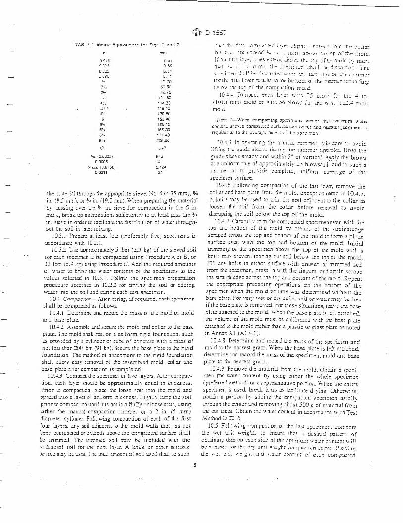
~ITT~ ::, 1 s5:-7..\3 _ .:. Metn c =.owva,er.:!: to, =1g!.. -: an :: 2
.. o.a,o 0 ::;: o.aJ:: c,.02r,
'•: 21~ ::?~·n
~ !·:
C.58~ .: l. ~
0 51,~ s~, 5J;~
a1,"
f;l
\-,., (0.0333) 0.0005
1/tJ 3~, f0.0750) 0.0011
mm
0 , ,
0.56 ca· G.:-~
i: -o 5:3.50 o~.i G
l Oi .6C 11<.30 ,10 .::; 120 .50 152 • O ,ss., o 165.30 171 40 20B.50
=mJ
9.!3 1.;
2.i 2' 31
lhc:: m:Heri1! through the appropriate sieve: ':'<o. ~ (4.75 mr:1), % in. (9 .5 mmi. o; l; ~ in. (19.0 mm). \Vhen preparing che mmeri:il b)' passing over Lhe 3; , in. sieve for compacl.ioo in the 6 in. mold, bre:ik up aggregJcions sufiicicnciy to :i: bis, p:css the :;,ii in. sie\·e in order co i:icilic:ite the distri::>u tion o{ w1cer ,hroughou t the soil in !:Her mi.~ing.
10.3.1 Prepare al least four (prefrrnbly ti•:e) spe:imens i.n :iccord:c.n::e with 10.2. I.
J0.3.2 Use 3!Jproxirnncely 5 Ihm (2.3 l:gJ of c.he sieved soil for e:i. ch specimen to he compacted using Procedure A or B , or 13 lbm (5 .9 l:g) usini; Procedure C. Add th~ required .?.mounts of warer to brini; ch::: ,v::m:r contrncs oi the spe::irn~ns co r.he , ·al ues sele:ted in l 0.3. l. Follow the spe::i.n,en prep:rr:i.cion procedure spe::tied in J0.'.:..2 for drytng the soil or adding w:i.cer into the soil md cu.ring e:ich tc:sE spe::imen.
10.4 Compactirm- Airer curing, if required, e:ich specimen shall b: compacted a.s foU ows:
l 0.-J.. l Decermine and record ,he mass of ch.c mold or mold :ind b:i.se pl:i.te.
I 0.4.2 Assemok and secure the mold a.nd coU:ir co ;he base place. Tne mold shaU rest on a uniform rigid foundation. such as provided by a : ylinder or cube of concrete with a m:i.ss of nm less th:i.n 200 lbm (91 kg). Secure the b:ise pl:lce co the rigid foundation. Tne method of atl.'.lchment co the rigid founda,ion sha! l allow e:isy removal or the assembled mold, co!J:i.r and b;;se place :i.fler compacl.ion is compleLed.
I 0 .4.3 Compact che spc::imen in fi ve layers. Afle r compuction, each layer should be :ipprm.imacely equal in thickness. Prior co compaction. place tht: loose soil into the mold :i.nd spreJd into a layer of uniform thickness. Lighliy c:i.mp the soil prior co ::ompacLion until it is oor i.n :i fiulfy or loose sc:ue, using ~i cher the manu:i.! compaction ra:nmt:r or a ~ in. (5 mm) diameter cylinder. Following comp:i,:: cioo or e:ich of the first four layers. any soil :idj:icent to the mo ld w:i.lls ch:i.c h1s nae bc~n cor.,p.icred or ~xLe nds :ibove the compacted ;.urfac:; sh:ill be Lrimmed. Tnc: L-ir:1.11d soil n.:iy !:le incl~!dcd with the add:,1011;;! soil for me: nc::xr byi:r . ..; k;,iJe or o;:hcr sui t:cble device m2.y ::ie us:d. Th~ ioo.l 1r.10u11r of soil used sh:il] bt su: h
5
,r.J · Ln: rilu, .:omp:1:t= c b y:::~ ~LfnL1: : :c:::.c:nc int , :n:: ::a lb::. ou auc. nc1~ ~~= ..:~e~ ~- ~n 1c m::-1 :.i:,t1v: !.11:- iiif of :.,1::.· ~ ok .. L uic ni''.h iJy :;; : do::::. :::::t~nd :.ioov:: ,he· t:Jr o iUJ: mu ld ::,: mor: cn.:r . u .. , c mm ,. ch c: spe:t:nc::-, :: ni.l U oc d:s::::ird.:d Tn i: ~p:.!.:1r:·1~r1 .,h:tl~ b:::· dL~.:J.ra;:;: \\·n~r. :.tL I~: oJov 0~1 Lh= :-:.imm!.::-io~ lf:c ri1·u li!ye• r::::ul(." in lhc: bmlur. o f the r:i;::::i:::~ c:::t:::nciing oel0v u, ::: LO~, of the compa:uon mold.
JC, -" - Cnmpac[ :::u:h l~ye~ v:rcn 25 ol ow for t.hc ..!. in. 1ICJi. r, mm, :nold or v.·Hh 5o blow..: fo r tne o :n. 115: . ..!. :run , molJ .
l',o-:-;: - -\.\~,::n cn mp:.t:::~mg. ;;p:;::tm:.:n:. w::rt::r thJr, opt1 mum v.::.iL::r
contcn~ un~v::n comp:.ii.:1et! :>LLriuL:::s t.:.:.u- oc:.:u:- and op:::-Jwr j ua~m=nt i~ n:qu u::d :.L· Lo Lht av:=r:ig:: hc:tg.IH of lhr .~pe::1m en
J0 . ..;.5 1n operJt ing th: mm u:i.l rammc:r, w.k: ::Jre co Jvoid lii:inf the guide slc::ve du rin_~ the rammer ups:iok::. Hold the guid= sl::ev= st::Jdy and within 5° of vercic J.1. Appl~· t.he blows al :i uni..iorm ral:: of :ipproxima t::ly :2.5 blows/mir. and in such a manner a; co provide complete: , uniform coverage of the spe: imen surfa::::.
I 0 . ..!.6 Follcrn·uif c omp:icti on of the b st Jny~r. remove the collar Jn: bi,c pl;ir: from th:: mold, ex::epl 2.s noted in l 0 . .c.. 7. A tni.r'e m2y be used tO rrim the soil ::idj:.icent co the coll:i..r co loosen the soil from the collar before r::mov:i.l co ;:i void disrupting che soil below the top of me mold .
IO . .J .7 CarefuU_v lrim the compa.cted speci..rneneven with lhe cop :ind hurrom of che mold by meJI1s of Lhc ,Lr:iightedge s.::r:iped a::ross the cop and bo[tom of the mold t(l fom, 2. p!J.ne surface e,·::11 wir:h the cop and bottom oi che mold. lniciul tnJT1~-:1ing oi the sp,::cir:1en .ibove chc: top of the mold v.·i:h a knife m::iy prc:vem tea.ring out sou below the top of [he mold. Fill any boles in ci:her surface wirh unused or uimm:::d soil from die spe::i.n,en. press in with :he iinge.:-s, anc :igJin s.:rape c.he str:iigh Ledge across the lOp :JJ1d boccom of th:: mold . Re pear che appropr.:i.re pn:::eding op::racions on the bottom of the sp::ci.."Tlen ll.'hcn the mold vol ume v.:1.s determined witho ut r.h e b:ist pl:!.cc. For ver:y wet or dry soils, soi.J or wacer m ay be lost if the b::..se plate is removed. For chese 5iruacions, le~ve ;he b;i;e olate :rn::iched to the mold. When th::: b::i.se oilce is left :ittJched. di: volume oi lhe mold mu5t be c:ilibr:iced widi m,: ba.se pbte ::i:c1ched co che mold rather th111 a pb;cic or glass p l::i.ce :is no ted in ,:\.nnex Al ( Al.4.1 ).
l 0.4.S Determine :ind record the mass of the specimen ;ind mold co the nearest gr:i.m. When the base place is kfc act2ched, d::ter;:1ine and record the mas; of che specimen, rn old :ind b:ts:: pbte lD the nearest g,-aru.
JOA.9 Remove the matc:riul from lhe rnolt.l. Obt:li.n 3 spec imen for w::icer contem by using ei ther the whole specimen (pre f~rred method .I or a represeocaci ve por..i on. When the encire spe:imc:n is used, break ic ttp to faciliu.,e drying. Other\,vise, obc:w1 a portion by s licing the comp:ic.:t~u spc.:cimen a:-i .iUy wough the ccncc.:r 1nd removing about 500 g of r.1:.1tcri.i.l Cro m the cut faces. Oht:.un che water contc:oL in :1c::ordai1ce wich Tes[ Method D 2:. 16.
J0.5 Fo!lov,(ng :-ompu.c tion of the IJ£r s;:iecimen. comp;:rre c.he w..:t unit weights to en5ure Lh1c :i des ired paccern of ootaininf dJC:! nn each side of th.:: aptim urn w::uc:r cr1 ncenc will be a::::aincd for [he: dry unil \Vtigh, t:0::1p:1cior. ..:t! r,,:: . Plo t: :ng L'le w:::t u,j: wi::;hr and w:1:c:r conr:::n, o f e:iL·h comp:i.:tcd
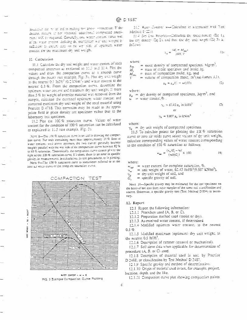
~ITT~ D 1557
5[r .. ..:u:1-~ . .::.i: , :; · ::-. :::~ :r: ~~:.!'.:.!!!; r_n= ::.:-i,:,. ·· ·::.!.L.::l~Or.. F d:J:: ll::.;:::.:r. r::1 1.:.=-r. L' n,J' :-:b:..::1 net: :idci1 ~: ') ria '. : f·:-"1:1:.1:::;d soi;::jm:::n. ,.1 i!. :J, r:::q.itrc:c. Genc:;-.. di:. , on~ v.:.i:.:- .:0nl~n. ·,·:i.lu:: w:::
o: :!1 ...... ·:1.::- ..: .. \!:::-n J::iinin~ U1... 111::::_-:~:...::"":· h .:· un:: \., :.:_;.!h~ 1~:
sl!rr:.:::::n: :=· :.;:,::~:-: a:..:::· or llt: w::· , 1a~ u1 oru;11L!::·1 v:::ite:-con1::11 : JO, !.fl::: m:1.\::num dr:, uni: \v:::.gh . .
11. Calcu::.it iun
11. I C:ii:.::d:H:: :h::: dr:- w11: w:::f;h: :l!ld ,,:~i::- :::Jnt:::n. oi ::Jch comp;i:Led spe::1rn~n ;13 expbm~a in 1 ! .:= :ind l : ..1 Plol the values .ind ar:.iv. th:: ::ompacL1on ::urv:: J ~ ::: .;;:noolh curie lhrough th:: oou1,;; 1 s;::c =~:imp!:. Fi g. :-1. PloL cir: t: ni : wcigh: w th::: n:1res: 0.J loUt/ (O.::'. l:..'-i1m·· .1 :.ind v.·J:::r ::cin1::nL w t:he n::ares; 0. l 7t. From t.h:: compa:tion curve. dw:m1ine th~ opLir.ium \1·:ner :onLenr :md m:iximum dry urn: weigh:. If more Lhan .5 7r by \\ ;:1gh: or oversize m:.1r::rial w:.1.; r::;11oved from ch:: samp l::, c:i.lculate t.hc corre:Ld opLimL::1~ wale r cont::1H a.nd corr::cr::d m:ix irnu-n dr:: uni: wei~h: of the tot:il marerial u$ing PracLic:: D 4 7 IS. This corr:::lioo m:iy be made co the appropri:ire field in pbce density Les: specimen r:ilher Lhan lO the J:ibor:uo~· t:,t spe::men.
l 1.2 Plot Lhe JOO '10 saruntion curve. V:!.lues of wat:r comen; for th= condition o( 100 ',r sa,:..tr:ition ::in be calc:.il:11::d a.:; expiJ.i...-,ed in J J.5 (see example, Fig. 3J.
Norr 8- Tn~ l(XJ '7i: s~ltUiJL1on ~un1: i~ an ~cJ i;i drJwing chc !.'.Dmp:ic
tion curv~ ?n:"' ;oit~ cont.1inin1,; mur:: Lhun Jpprn\... :r..irc:J:, 10 'ii- fint ;; ac wat:=i cont~nc.; well abov: t."lpumurrt the cwo cur,·e~ gen::rnlly b~cnm~ rou_ghJ:·· ?:ll":.tli~f with rh:: w :! .:;ide <.>f Lf\::- compaction cur:: b~~w~=n 9:! 7c 10 95 % sarur.ition. Theorctic~lly. th~ cumpact,on curve c:irutC1t plot lO Ule rig.ht oiLh: H)() ~ ;Jrui.Jtion curve. If ir do:=.,. ch:!~ l:; :in ~rror in ;~cilic £rJ vi1y. in me.:i,ur: m::nrs. in c~k:u!atiom. ir. r:::.c;1 proc:Uu r~s. or in plotl~ng.
Noi£ 9- Th:: 100 :;( ;;;Jru:-:Jlion cur·:!' i;; 5c1m~t1m:~ r:.: f=rr:::d to 1 ~ th~ z~ro :u..r v0l1..i:; ~ur.·e or Ul:: cnm?lcce ::. .:nur..1tior. ctrve.
':.
~
= IJ6
!!:?
'"'
1: J.
1 :!0
\ "
COM ? ACT ION -;-::::ST
,.i.wr. ...
~ -.c;A
?o ~ • I ::.C 1::,1jifr:_
:a.,
. ,c--15
.., -.. :_;.. ::, ~- -~,..:l ,: "',
- 1:.~
,, .i....:.....,._, .S.------,i
'IIU.Tc:7. ::or<rrJ,n - w - X
FIG. 3 :::~am;,le Compac:ion Curve ? lo r;1ng
--
'-::r
ii
l j .~ ~L.!t::' · ... - ! •'1/[.· .r:: 1-1-: 1i:u:::u~ 1:-: i:.:::or.::!.n::!:' \ \ 'i~ T ::s: M~:.hcc [• :: i r
1: ..! [;-i :_.,u V\:;.!.'h:},-':.1J:t.:J.2t~ ch~ mo1.,.ct ::n:. :!:: ,=q Ii mt d~ a~n,:r• /I:.c ::'. 1. and thcr til t: dr: uni· us: g-h: (s q :i I a :
ioliow:
1vhere
Pm ,11, Mmu 1·
i Af: - 1\-!11111 I P.,, -= J IJ(l(J \ .
= r.1ois: d:::nsi•y of compa::t::d spe::i...-n,r.. :\lg 1;i1:. .
ma:;; oi mois: specimen and mold. l:i;, m:!.5~ of :ompa:tion r:iold , 1:g, :ind volurnr.: of compaC[ion mold, m~(sei Anne:;.~.] l.
/ 11
P, = p,,,1(1 + w/J 00 ) ('.:.;
where: Pt.1 = dry density o f compa: ted sp::::im::n, Jvlpn=', :ind w = water conLenL, % .
"lo = 62 . .::Jj P, in lbflft3 (J )
or
-y, = 9.R07 p, in l.:.'l/rr.3
i\.·here: -Y<.J = dr:,· unit weight of compacted spe:imen.
ll.5 To : akl!!:ice poui~:; for plottin; ch:: lOC 'i: , :i::-urJtion curve or zero cir voids cunrc se\ecc v:ilues o( dry unic weighl, calc.:ul:.ite : orr::spond in~ valu::s oi 11·au~ r comen: corresponding LO the condition of 100 % sarnr:irio11 :rs follows:
where: \,\.'S.11
-y.., -Yu c,.
c-v •. 1c_, - 1rl . w.,, = (-yd)(G..J X !00 (4)
w:iter content for complete sarurmion, '1c, unit weiclit of water, 6::'..4-3 lof/fc:; (9.S07 k.."f/mJ), drv unit -wei 1:hc of soil, and · sp~ciiic £,:!Vity of soi l.
NciTE j{L-.Speciik ~-aviry m:iy be e;rimar:::d for lh~ c~;t ~p=~L,1::r: on t:.h~ ba.1i., of ce;t <iJW from ntber ,:unp les of che same ,oil :la;,iiic:uion and ;our~=- Other.,.·,se. J Sp:!:i.Jic g:-J•·ir:• r,:;r (T~;; >·leLhoc D S5.!J is a~ces
; :.iry.
.I:!.. R eport
12.l R~port th: following inforrnacion: 12 .l. l Proc:dure used (A, B, or CJ. 1::'..1.2 Prepar;irion mechod used (moist or dry ). 12.1.3 As-received water concem, if dete:mined. 12.l.4 \,Joditied opumurn w::ll~r concem, co the nt:a.rest
0.5 9c. 12. 1.5 ;\.1odi.tied m:ixi.mum (optimum) dry unit weigh t, to
the nc::a.rest 0.5 !bf/fr'. 12. J .6 DescripLion of ramm: r (1m.11u:i.l or m-:cha.nic;:i l) . 12.J.7 Soil ,i:::ve d:it:i when :ipplic:ible fo r di:: t::rmin:ilion 01·
proc:::durc (.-\. B, or C\ used. 12. l .S Dc,cription of m:i.teri;:il used i.J1 Lest. by Practice
D 2-l-SS, or ::l..!ssificalion by T;:sc :VfeLhod D 2..!.S7. 12. 1.9 Spc:c:tic gr1 vity :inJ melhod nf deu:-m:.naLion . 12.1 .10 Origi.n or nmerfa l used in tc:sl, for .::o:::i.mpk projcc:,
Joc:icion. depth, :ind t.lit: like. 1 ::'..] .l l Compuctior. cu,ve plot ,hov.·i..ng comp;:ic:ilJn point.~

•ITJ~ r -1 --riu11 !..I ,:::;~.
:::::~bl!_-::: .::ir.i~a::uur. :u.-vc. anC: JC{ ft :::i:u;-:i:ion 8,::.--1. . nc: po::siol~ tt o.:,u.ir. i nio:::.:i:..:or. or OJ::!::
:u:--::.: r,oin: o:· ::n:1~:.r71um Cr:· uni~ w!!tg-h: 1nG opt:m:..!rr, \.v~cc:-:::ont::n:.
o~:J.~_,:- Ln:::-~ :.~ n1.. cu1~~ :-:1:::noC O:- dev.:r:.·111111:; LI .. : :..i..Jc:~- u;
modiii.::.:: :::..::::::,t.:..-:- d;_ un:: w::i~h: :J.rJc or..:rr.~n. w:ite; ::::::>n -] ::. l l.: Ci\'.::;~::: :::::.-rr.:::::aor d;:::-: if L.:sed 10:::iudin;: th= t-:11:.
ov::::::.::c fr:.i.:: ior 1:0:ir~:c fr:i~:ioo ;. ?0 ir. S:-r .
13. Pr?:!Cision :inc: B:a.s
! ::. J ?r,I, : .,1r•1?- ['ac::: ar: b~,n; :•,alt::ned lC' dcrermin~ :he pr~c,;ion of lh:3 t:Sl methoc. ln addition. p..:r:.in:::n: d:ir.;_ i.;; being soli:::it:::c! irorr. us:::n of th:: res, method.
1 ~. J.:.e.vwordo
J.:;..J cor:1p;:icLon ~har:i:::t::ri.sttc:: d:::nsi,y: ,mp:i::: : :::omp:i.:-uon us,nf nc,~:ri:c :lTor;, i:J.bor:itor: t~:;t~; m1dific::d proctor t~s,, motstllf::-den:;Hy :un1:::s: soil cor.1pi.1::cion
A!'JNEX
(i\[JJ1dator)' lnform:ition l
AL vou:;-.rr OF COMl 'ACTJ Q.',' MOLD
Al.I Scope
A J. l.J Tnis anne:i: des::ribes the procedure for determining che volu1:Je of ;:i comp;:iction mold.
A J. l.:. The volume is dete;mined by a warer-tiUed metilod and ch:ck::d hy a linear-meJsur::mcnt method.
Al.:. Apparatus
.A.l.2 . l in addition to the appararus list:d io Section 6, che foUowinf items are required:
Al.2.J. I \-'ernie.-or Dial Caliper, having a mcJSuring range of ar Je:is: 0 co 6 in . (0 to l 50 nn1} :ind re:id:ibl::' ro a: l:::m 0.001 in. (0.0:. mm).
A 1.2. J.2 lnsidt· Micrame!er, h:iving a me:i.suring range of at le:i.st:. to 1:. in. (50 to 300 mm} a.nd read:ible ro a, l::m 0.001 in. (0.0:. mm) .
Al.2.1.3 Plas1ic or Glass Plates- Two pl:i.stic or !:!i;!SS
pbi::s abou: S in.~ by \1~ in. ::hid: COO mm= by o mm). -A l.2.1.4 Th!?F/fl/J/11 !: lcr- D to 50°C range, 0.5°C gTJdua
tions, confor:uinf ro the r~uiremencs of Specification E l. A l.2.J.5 Sropcock Creese or si.mil.ir se:i l:inc .. A L:?..1.6 Miscellaneous equipmen1- Bulb syringe, rowels,
etc.
Al.3 Precautions
A J.3. I Perform this procedure in :in are:i isobtcd from drafL, or extreme ternpt:rarure flucru;:itions.
Al.4 Procedure
.~.l.4.l Yl'a1er-Filling Mi:1hod: Al.4.J. J L ightly grc:isc che bonom of the comp:i::tion mold
:ind place icon one of the pbscic or glass p!Jtes. L ightly gre:ise che top of the mold. Be: ca..rdul not co gee grease on the inside of the mold. If it is necess.'.1..-y w use the b:ise pl:ite, as noted i.n 10..J..7. pbce che gr:.:ased mold onto lhc bi.I.Sc plJtc and secure wirh the locJ.-...in; sllids.
. .i. I..:J..1.2 Dcccrmin::: me nw.ss of the greased mold J.nd both plastic or glass plates Lo the m:arest 0.01 lbrn (1 gJ and re:::ord. \.Vheo the b::se plate is being us::d in lic:u o[ the botcom plastic or gl.is:; plate: determine the rr.:iss of the mo ld, base pl.ite and :i. single pl :!..stic or f!:lSs pi:J.re to be L.:scd on top of ~he ;:,old m the ne:ir:::st 0.0 l Ihm I l g) Jnd record.
'
_,u .~.1.3 ?lace Lfie mold and the bottom p!Jce on a firm, level surfoce :ind fiU the: mold wi c:h w;:i[er co siifhlly above ics rim.
Al.4.J.j, Slid: i.he se::ond pl;:ite over the cop sur.:ic~ of rbe mold so tb: ih:: mold remains con1plecely filled with 11,ate r md air bubbles ar::- no! enLI:i.pp::d. Add or remove wJter :LS
ne::ess:rry wi::.h a bufo syringe. Al.4.J .5 Co!:lpl:::tdy cir}· any excess w:it::r from the out.side
of the o old and pl:it~s. A l.4.J .6 Detcnui.ne the m;.!.Ss of th: :nold, plates and w;:iter
;ind rc::ord to rhe neares: 0.01 lbm ( I £).
A.1.4. I. 7 D::::em1in:: the t~mpcr:nure of the warer in th:: mold co the nea.res, l °C :ind re::ord. Dece~r.iine and re:::ord Jie absolutz denstty of w:it:::r from Table A.l.l.
A 1.4.1. S C:ilculate the m.!.55 of 1,::1.rer in the: mold by subu-:icti.ng che r.iass d::'termi.ned in ,!, ! .~.1.2 froin che m:i;;; determined i.n Al.~.1.6.
Al.4.l. 9 Ca.kubt! the volt:me of w:i.ter by dil'iding che m::?ss o f w:.itcr b\· th: demirv oi w:iter and re:::ord :o che ne:irest 0.000 l f~( l ::r.)). .
A!.4.1. lO \.\'hen rhe ba.se plate is used for rhe :alibr:it.ioo of the mold volume repe:it sr=ps Al.4.l.3-AJ.4.1.9.
A 1.4.~ Linear M~as11r~me111 !vl:!tho d.: A J .-L:2. l Using either the vernier :;;:i,Jiper or Lhe inside
micrometer, measure the diameter oi the mold si., tim~s a t che top of t:he mold and six times at the bottom of the mold ;p:ici.ng e;:ich of the six cop il.Ild bocrom measuremenl5 equaUy around the ci rcumference oft.ht mold. Record lhe 1·:ilues tot.he nearest 0.001 in . (0.0:. mm).
TAB L:: A1.1 Density of Water"
T2moeran.ir:!, "C ,·r=> , a 10..: -1) 19 (55.2) 20 (56.0) 21 (59 5) 2~ (- 1.oi 23 (73 tl) 2~ (15.:::! ) 25 ;- :-.OJ 26 t- 5.8}
Oer.srry of Water. y/ mJ
0 .99852 0 .998.!J 0.99823 0.99SG2 0.99779 C.99,55 0 99;-33 0.99:0:-0.99561
-'Values :H,e:" :r.ar. srowr may ::>: o~ta1neC ov reiernn£ re- the .'-lanC:Jca11.: ui C.1ar;;1srry .anc =:.,ys,.=-s Cl"',e:nu:.J.! =iu:::mer ?uoiisi11ng Cc .. Cit-velanc OH.

~m,~ - -,--~ lti] I L. '::; ::, I
_.!._: . .:! .2.~ lisw if tn~ vern1:::; .:::J.Jlpe:-. me:1sur:.: th:.- 1.ns1oc h!::igh~ or the: :ncilc. o.\ makrn; mree m~U!Jur~m.:.:nL eq~2.u:. spa::ed arounc u1~ ::u-:ur.1t:::r::ncc o:-me: mole. F::::::or: ":.Ju~.- tc che nt::ir::s: 0.001 in. 10.c: r.u:11 .
. C...1.~.~-] CaJ:~tat~ ~n:: :?ve;-:1~:: co~ d~1rno::te:- J-.·::;-:.!!!:. oo:. row diam~c::r mC ~.,1er:.:.f"= he!~h~.
A 1.-l.::'. . .!! C:i.J:ubt::- th,· vohcmc oft.be .oold Jnd re:: orc ,c die o::::mes: c.ooc1: [:~ ( 1 :::n31 U5 tn;: E.:i .t..l.J (fo;- in::b-pound ' 0~ r r for SI;:
where: V
• 1 .. )(h)l1l, - JJ \ = (!ciJll 7:!8J
1 .. 111i11,1, - ii.? \/ - .
- (16}( lrY l
volume of mold, f2 (crn 3) ,
nver:ige heigh[, in. (mm), h cf,_ = nv::::-:ige top dinr:ierer, in. (mm),
r..:..1.1 )
!A!.21
::, = ~,\~:ng~ oor~::ini C;:::i~t~; ~:· 1 ::1~1 ..
1. :--~" = : onsr-:1n : Lt• :.:onv::r~ tL tL r:·. J1 1c 1.1,·' cons,m· [C· ::onv:::r: :n:i: w ::m··.
A.: . .5 Compa:-ison o~ R.l!.Su! ts
Al..:';_! ~= voiu:::i.: oo:cint:c b: t !:he:- r.1:U1riC: sh:iu;c o, wi:hm che volume to le~::mce r::oui.~:;nmc., of o.,.1 :i.nc:: ~ .. .::.
."-.1.5 .2 Th:: dL"fc:rem:e i:ietwe:::n .:ii:: rwo method . .shou1.: no: c;,:c:::::d 0.5 '7r oi :.he nominJi valume of tn:! mol:::i
A 1.5.J Repent rhe determin:uion of vol urne i; mes::: .:r:cena a.re nor me~.
Al.5.4 Failure to obt.ain s:i:..isfactory ngreemen:: be!we::n r.he cwo mer.hods, even J.fter several rri:ils, is ;rn indic::i!.ion tha· rhe mold is i:iadly defom1ed anci should be rep!J:::ec::.
Al.5.5 Use t.he volume of the mold deLermined usin& rhe water-fillin~ method as che :issignd volume vaiue ior c.:l.! :::ulati.ng the moist nnd dry density (see 11.4 ).
Tne Amen=an SoaelJ' rar Tes1Jng and ,1,,farar.aJ:; ,·a1<es no pasitJCJn resoeamg tne va fdiry at an_v parent ngnrs asseneC in cannecuon wftn c1ny u~m menuoned in this srandarC. Use.rs of mJ.S si.anaard are :1.or~ssly advi'sSC r:,a t 01:rermmauon of th~ valtdtf)' of any suet aarEn: ngnis. and me nsk ol ,nfnngement of sue.; ng,,rs. arc enr,re,y rne1r own respans,a,hry.
ln:s sra,,a~,c .?: sub;e:: ta re-v1Sion at any rim:: ~11 tne resaonsitJle t=chnica! =amminae and must oe rev1:!wed every li ... ·e years a.-,(1 .: :,ar .re:1•1sE'C. a1tnerrc1:p:ircv&-d ~r w!fnt:raw."i. You,,. ::::;r.:.~e..-::s ar: :,'1vtle~ e:.~"letlot r:v:s .. ~r. c ,1 r.>us sra,,;ca."!1 a.· ;c.' 3rt=.·!1:Jr.a.' srar.aar='! and snault:' jC ddaressec r:; AST/vi Headauaner=. Your C::Jtn ments will receN: careiui cons,a:ro11Dn at a mee(lng al :;,e res:1onsiDI~ tecnmcal cammmr:?e, wn,,n you mav arrend. If you le~/ mar your comments ha ve nor recerv2d a lair oe3nng you sr.au/C ma.ke- vour .1,~ws known re tne A5TM Commme~ or: Stancarrs, TOO Barr Har.Jo.' Orrv~. West Cor.snohocken. PA 19-:.2£. ·
s
APPENDIX D
Western Regional Climate Center Rainfall Data
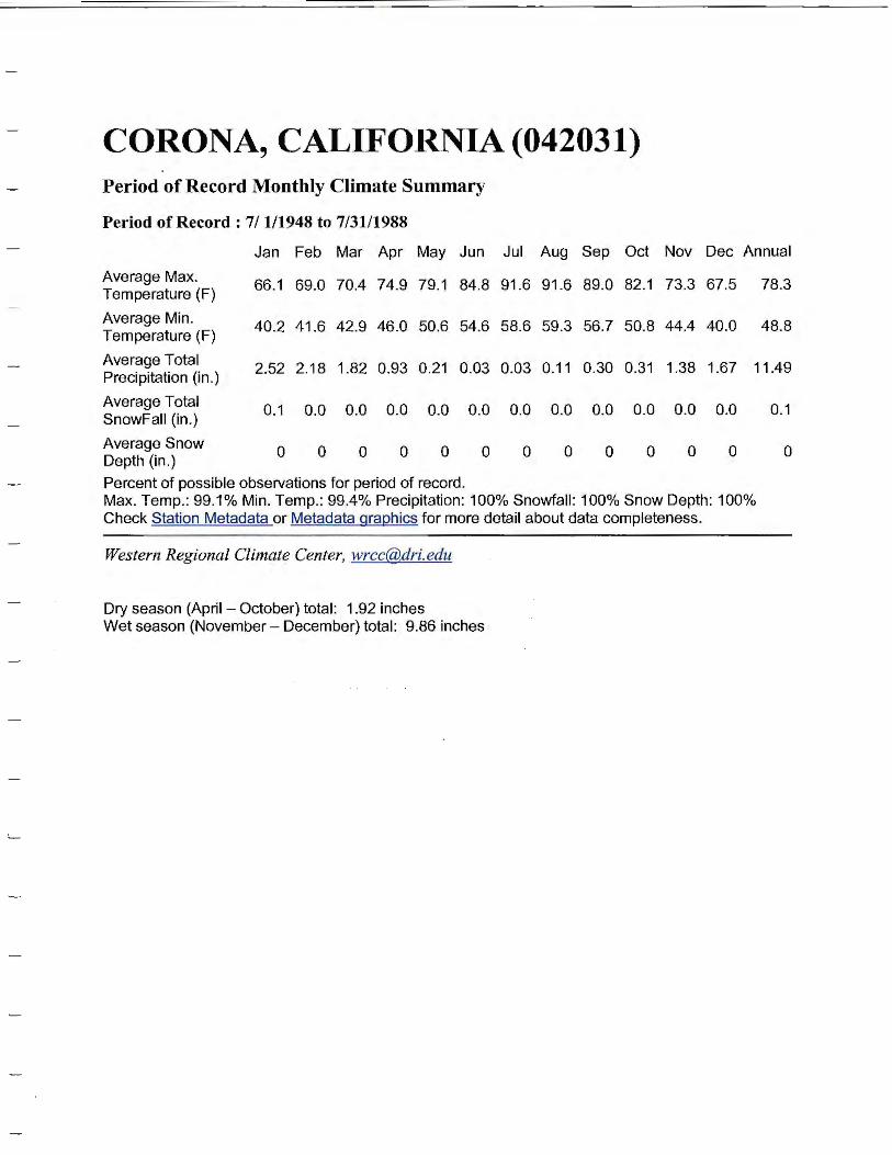
CORONA, CALIFORNIA (042031) Period of Record Monthly Climate Summary
Period of Record: 7/1/1948 to 7/31/1988
Jan Feb Mar Apr May Jun Jul Aug Sep Oct Nov Dec Annual
Average Max. 66.1 69.0 70.4 74.9 79.1 84.8 91.6 91.6 89.0 82.1 73.3 67.5 78.3 Temperature (F)
Average Min. 40.2 41.6 42.9 46.0 50.6 54.6 58.6 59.3 56. 7 50.8 44.4 40.0 48.8 Temperature (F)
Average Total 2.52 2.18 1.82 0.93 0.21 0.03 0.03 0.11 0.30 0.31 1.38 1.67 11.49 Precipitation (in.)
Average Total 0.1 0.0 0.0 0.0 0.0 0.0 0.0 0.0 0.0 0.0 0.0 0.0 0.1 SnowFall (in .)
Average Snow 0 0 0 0 0 0 0 0 0 0 0 0 0 Depth (in.)
Percent of possible observations for period of record. Max. Temp.: 99.1% Min. Temp.: 99.4% Precipitation: 100% Snowfall: 100% Snow Depth: 100% Check Station Metadata or Metadata graQhics for more detail about data completeness.
Western Regional Climate Center, [email protected]
Dry season (April - October) total : 1.92 inches Wet season (November - December) total: 9.86 inches
~