Aligned PLGA/HA nanofibrous nanocomposite scaffolds for bone tissue engineering
Upload
independentCategory
view
3download
0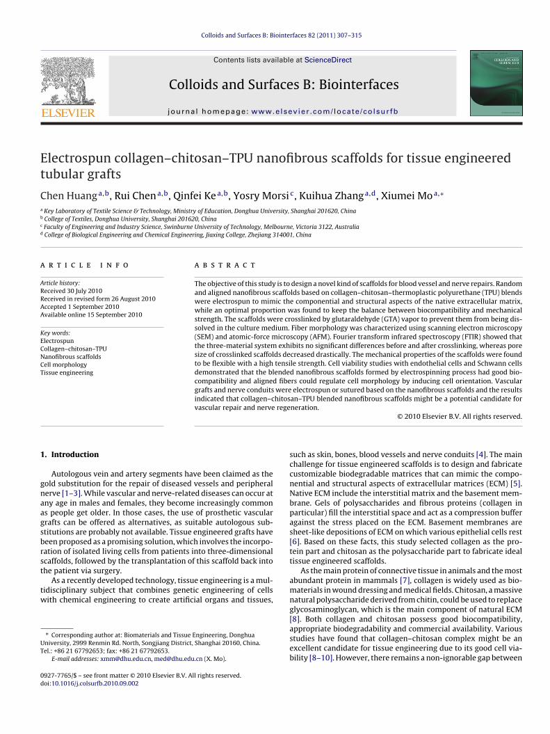
Et
Ca
b
c
d
a
ARRAA
KECNCT
1
gnaagsbrst
tw
UT
0d
Colloids and Surfaces B: Biointerfaces 82 (2011) 307–315
Contents lists available at ScienceDirect
Colloids and Surfaces B: Biointerfaces
journa l homepage: www.e lsev ier .com/ locate /co lsur fb
lectrospun collagen–chitosan–TPU nanofibrous scaffolds for tissue engineeredubular grafts
hen Huanga,b, Rui Chena,b, Qinfei Kea,b, Yosry Morsi c, Kuihua Zhanga,d, Xiumei Moa,∗
Key Laboratory of Textile Science & Technology, Ministry of Education, Donghua University, Shanghai 201620, ChinaCollege of Textiles, Donghua University, Shanghai 201620, ChinaFaculty of Engineering and Industry Science, Swinburne University of Technology, Melbourne, Victoria 3122, AustraliaCollege of Biological Engineering and Chemical Engineering, Jiaxing College, Zhejiang 314001, China
r t i c l e i n f o
rticle history:eceived 30 July 2010eceived in revised form 26 August 2010ccepted 1 September 2010vailable online 15 September 2010
ey words:lectrospunollagen–chitosan–TPU
a b s t r a c t
The objective of this study is to design a novel kind of scaffolds for blood vessel and nerve repairs. Randomand aligned nanofibrous scaffolds based on collagen–chitosan–thermoplastic polyurethane (TPU) blendswere electrospun to mimic the componential and structural aspects of the native extracellular matrix,while an optimal proportion was found to keep the balance between biocompatibility and mechanicalstrength. The scaffolds were crosslinked by glutaraldehyde (GTA) vapor to prevent them from being dis-solved in the culture medium. Fiber morphology was characterized using scanning electron microscopy(SEM) and atomic-force microscopy (AFM). Fourier transform infrared spectroscopy (FTIR) showed thatthe three-material system exhibits no significant differences before and after crosslinking, whereas pore
anofibrous scaffoldsell morphologyissue engineering
size of crosslinked scaffolds decreased drastically. The mechanical properties of the scaffolds were foundto be flexible with a high tensile strength. Cell viability studies with endothelial cells and Schwann cellsdemonstrated that the blended nanofibrous scaffolds formed by electrospinning process had good bio-compatibility and aligned fibers could regulate cell morphology by inducing cell orientation. Vasculargrafts and nerve conduits were electrospun or sutured based on the nanofibrous scaffolds and the resultsindicated that collagen–chitosan–TPU blended nanofibrous scaffolds might be a potential candidate for
rege
vascular repair and nerve. Introduction
Autologous vein and artery segments have been claimed as theold substitution for the repair of diseased vessels and peripheralerve [1–3]. While vascular and nerve-related diseases can occur atny age in males and females, they become increasingly commons people get older. In those cases, the use of prosthetic vascularrafts can be offered as alternatives, as suitable autologous sub-titutions are probably not available. Tissue engineered grafts haveeen proposed as a promising solution, which involves the incorpo-ation of isolated living cells from patients into three-dimensionalcaffolds, followed by the transplantation of this scaffold back into
he patient via surgery.As a recently developed technology, tissue engineering is a mul-idisciplinary subject that combines genetic engineering of cellsith chemical engineering to create artificial organs and tissues,
∗ Corresponding author at: Biomaterials and Tissue Engineering, Donghuaniversity, 2999 Renmin Rd. North, Songjiang District, Shanghai 20160, China.el.: +86 21 67792653; fax: +86 21 67792653.
E-mail addresses: [email protected], [email protected] (X. Mo).
927-7765/$ – see front matter © 2010 Elsevier B.V. All rights reserved.oi:10.1016/j.colsurfb.2010.09.002
neration.© 2010 Elsevier B.V. All rights reserved.
such as skin, bones, blood vessels and nerve conduits [4]. The mainchallenge for tissue engineered scaffolds is to design and fabricatecustomizable biodegradable matrices that can mimic the compo-nential and structural aspects of extracellular matrices (ECM) [5].Native ECM include the interstitial matrix and the basement mem-brane. Gels of polysaccharides and fibrous proteins (collagen inparticular) fill the interstitial space and act as a compression bufferagainst the stress placed on the ECM. Basement membranes aresheet-like depositions of ECM on which various epithelial cells rest[6]. Based on these facts, this study selected collagen as the pro-tein part and chitosan as the polysaccharide part to fabricate idealtissue engineered scaffolds.
As the main protein of connective tissue in animals and the mostabundant protein in mammals [7], collagen is widely used as bio-materials in wound dressing and medical fields. Chitosan, a massivenatural polysaccharide derived from chitin, could be used to replaceglycosaminoglycan, which is the main component of natural ECM
[8]. Both collagen and chitosan possess good biocompatibility,appropriate biodegradability and commercial availability. Variousstudies have found that collagen–chitosan complex might be anexcellent candidate for tissue engineering due to its good cell via-bility [8–10]. However, there remains a non-ignorable gap between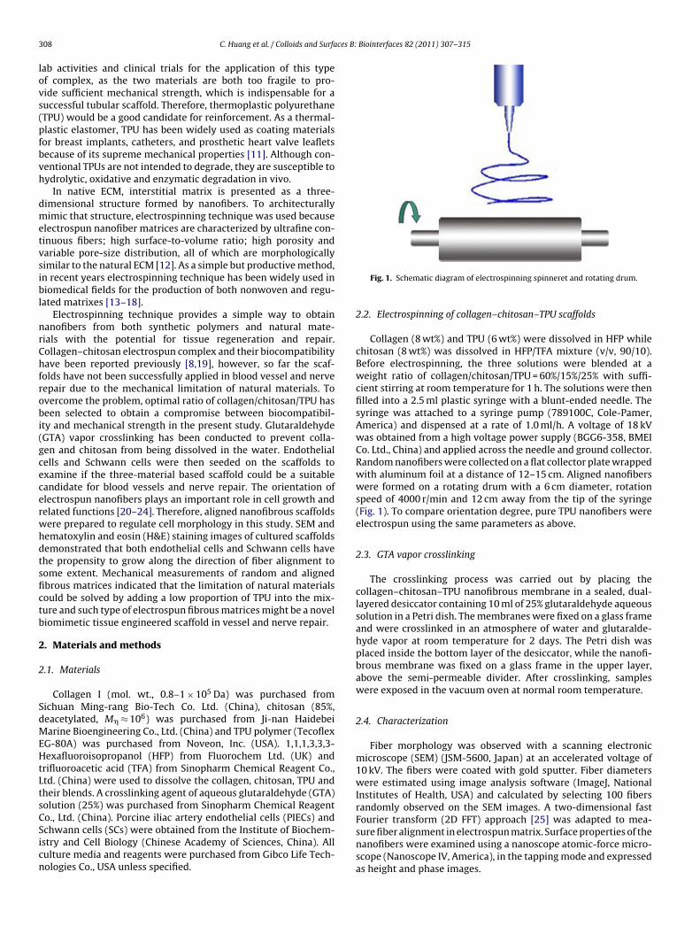
3 ces B: Biointerfaces 82 (2011) 307–315
lovs(pfbvh
dmetvsibl
nrChfrobi(gcecerwhdtsfictb
2
2
SdMEHtLtsCSicn
08 C. Huang et al. / Colloids and Surfa
ab activities and clinical trials for the application of this typef complex, as the two materials are both too fragile to pro-ide sufficient mechanical strength, which is indispensable for auccessful tubular scaffold. Therefore, thermoplastic polyurethaneTPU) would be a good candidate for reinforcement. As a thermal-lastic elastomer, TPU has been widely used as coating materialsor breast implants, catheters, and prosthetic heart valve leafletsecause of its supreme mechanical properties [11]. Although con-entional TPUs are not intended to degrade, they are susceptible toydrolytic, oxidative and enzymatic degradation in vivo.
In native ECM, interstitial matrix is presented as a three-imensional structure formed by nanofibers. To architecturallyimic that structure, electrospinning technique was used because
lectrospun nanofiber matrices are characterized by ultrafine con-inuous fibers; high surface-to-volume ratio; high porosity andariable pore-size distribution, all of which are morphologicallyimilar to the natural ECM [12]. As a simple but productive method,n recent years electrospinning technique has been widely used iniomedical fields for the production of both nonwoven and regu-
ated matrixes [13–18].Electrospinning technique provides a simple way to obtain
anofibers from both synthetic polymers and natural mate-ials with the potential for tissue regeneration and repair.ollagen–chitosan electrospun complex and their biocompatibilityave been reported previously [8,19], however, so far the scaf-
olds have not been successfully applied in blood vessel and nerveepair due to the mechanical limitation of natural materials. Tovercome the problem, optimal ratio of collagen/chitosan/TPU haseen selected to obtain a compromise between biocompatibil-
ty and mechanical strength in the present study. GlutaraldehydeGTA) vapor crosslinking has been conducted to prevent colla-en and chitosan from being dissolved in the water. Endothelialells and Schwann cells were then seeded on the scaffolds toxamine if the three-material based scaffold could be a suitableandidate for blood vessels and nerve repair. The orientation oflectrospun nanofibers plays an important role in cell growth andelated functions [20–24]. Therefore, aligned nanofibrous scaffoldsere prepared to regulate cell morphology in this study. SEM andematoxylin and eosin (H&E) staining images of cultured scaffoldsemonstrated that both endothelial cells and Schwann cells havehe propensity to grow along the direction of fiber alignment toome extent. Mechanical measurements of random and alignedbrous matrices indicated that the limitation of natural materialsould be solved by adding a low proportion of TPU into the mix-ure and such type of electrospun fibrous matrices might be a noveliomimetic tissue engineered scaffold in vessel and nerve repair.
. Materials and methods
.1. Materials
Collagen I (mol. wt., 0.8–1 × 10⁵ Da) was purchased fromichuan Ming-rang Bio-Tech Co. Ltd. (China), chitosan (85%,eacetylated, M� ≈ 106) was purchased from Ji-nan Haidebeiarine Bioengineering Co., Ltd. (China) and TPU polymer (Tecoflex
G-80A) was purchased from Noveon, Inc. (USA). 1,1,1,3,3,3-exafluoroisopropanol (HFP) from Fluorochem Ltd. (UK) and
rifluoroacetic acid (TFA) from Sinopharm Chemical Reagent Co.,td. (China) were used to dissolve the collagen, chitosan, TPU andheir blends. A crosslinking agent of aqueous glutaraldehyde (GTA)olution (25%) was purchased from Sinopharm Chemical Reagent
o., Ltd. (China). Porcine iliac artery endothelial cells (PIECs) andchwann cells (SCs) were obtained from the Institute of Biochem-stry and Cell Biology (Chinese Academy of Sciences, China). Allulture media and reagents were purchased from Gibco Life Tech-ologies Co., USA unless specified.Fig. 1. Schematic diagram of electrospinning spinneret and rotating drum.
2.2. Electrospinning of collagen–chitosan–TPU scaffolds
Collagen (8 wt%) and TPU (6 wt%) were dissolved in HFP whilechitosan (8 wt%) was dissolved in HFP/TFA mixture (v/v, 90/10).Before electrospinning, the three solutions were blended at aweight ratio of collagen/chitosan/TPU = 60%/15%/25% with suffi-cient stirring at room temperature for 1 h. The solutions were thenfilled into a 2.5 ml plastic syringe with a blunt-ended needle. Thesyringe was attached to a syringe pump (789100C, Cole-Pamer,America) and dispensed at a rate of 1.0 ml/h. A voltage of 18 kVwas obtained from a high voltage power supply (BGG6-358, BMEICo. Ltd., China) and applied across the needle and ground collector.Random nanofibers were collected on a flat collector plate wrappedwith aluminum foil at a distance of 12–15 cm. Aligned nanofiberswere formed on a rotating drum with a 6 cm diameter, rotationspeed of 4000 r/min and 12 cm away from the tip of the syringe(Fig. 1). To compare orientation degree, pure TPU nanofibers wereelectrospun using the same parameters as above.
2.3. GTA vapor crosslinking
The crosslinking process was carried out by placing thecollagen–chitosan–TPU nanofibrous membrane in a sealed, dual-layered desiccator containing 10 ml of 25% glutaraldehyde aqueoussolution in a Petri dish. The membranes were fixed on a glass frameand were crosslinked in an atmosphere of water and glutaralde-hyde vapor at room temperature for 2 days. The Petri dish wasplaced inside the bottom layer of the desiccator, while the nanofi-brous membrane was fixed on a glass frame in the upper layer,above the semi-permeable divider. After crosslinking, sampleswere exposed in the vacuum oven at normal room temperature.
2.4. Characterization
Fiber morphology was observed with a scanning electronicmicroscope (SEM) (JSM-5600, Japan) at an accelerated voltage of10 kV. The fibers were coated with gold sputter. Fiber diameterswere estimated using image analysis software (ImageJ, NationalInstitutes of Health, USA) and calculated by selecting 100 fibersrandomly observed on the SEM images. A two-dimensional fastFourier transform (2D FFT) approach [25] was adapted to mea-
sure fiber alignment in electrospun matrix. Surface properties of thenanofibers were examined using a nanoscope atomic-force micro-scope (Nanoscope IV, America), in the tapping mode and expressedas height and phase images.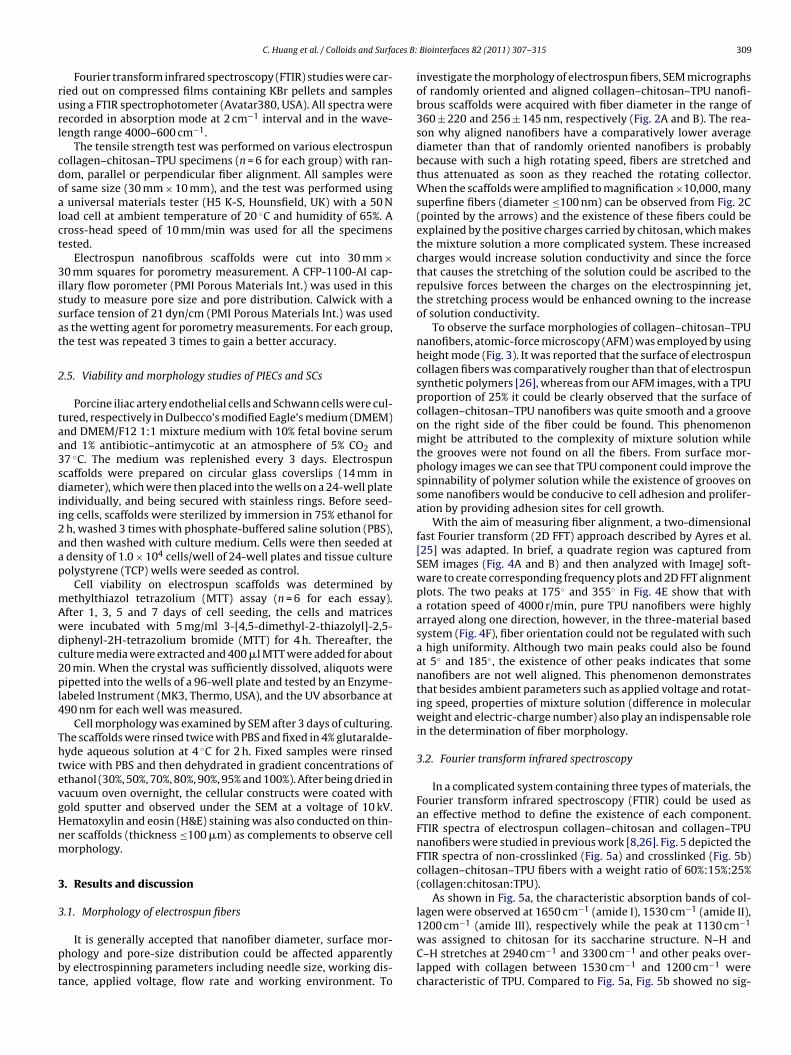
ces B:
rurl
cdoalct
3issat
2
taa3sdii2aap
mAwdc2pl4
ThtevgHnm
3
3
pbt
C. Huang et al. / Colloids and Surfa
Fourier transform infrared spectroscopy (FTIR) studies were car-ied out on compressed films containing KBr pellets and samplessing a FTIR spectrophotometer (Avatar380, USA). All spectra wereecorded in absorption mode at 2 cm−1 interval and in the wave-ength range 4000–600 cm−1.
The tensile strength test was performed on various electrospunollagen–chitosan–TPU specimens (n = 6 for each group) with ran-om, parallel or perpendicular fiber alignment. All samples weref same size (30 mm × 10 mm), and the test was performed usinguniversal materials tester (H5 K-S, Hounsfield, UK) with a 50 N
oad cell at ambient temperature of 20 ◦C and humidity of 65%. Aross-head speed of 10 mm/min was used for all the specimensested.
Electrospun nanofibrous scaffolds were cut into 30 mm ×0 mm squares for porometry measurement. A CFP-1100-AI cap-
llary flow porometer (PMI Porous Materials Int.) was used in thistudy to measure pore size and pore distribution. Calwick with aurface tension of 21 dyn/cm (PMI Porous Materials Int.) was useds the wetting agent for porometry measurements. For each group,he test was repeated 3 times to gain a better accuracy.
.5. Viability and morphology studies of PIECs and SCs
Porcine iliac artery endothelial cells and Schwann cells were cul-ured, respectively in Dulbecco’s modified Eagle’s medium (DMEM)nd DMEM/F12 1:1 mixture medium with 10% fetal bovine serumnd 1% antibiotic–antimycotic at an atmosphere of 5% CO2 and7 ◦C. The medium was replenished every 3 days. Electrospuncaffolds were prepared on circular glass coverslips (14 mm iniameter), which were then placed into the wells on a 24-well plate
ndividually, and being secured with stainless rings. Before seed-ng cells, scaffolds were sterilized by immersion in 75% ethanol forh, washed 3 times with phosphate-buffered saline solution (PBS),nd then washed with culture medium. Cells were then seeded atdensity of 1.0 × 10⁴ cells/well of 24-well plates and tissue cultureolystyrene (TCP) wells were seeded as control.
Cell viability on electrospun scaffolds was determined byethylthiazol tetrazolium (MTT) assay (n = 6 for each essay).fter 1, 3, 5 and 7 days of cell seeding, the cells and matricesere incubated with 5 mg/ml 3-[4,5-dimethyl-2-thiazolyl]-2,5-iphenyl-2H-tetrazolium bromide (MTT) for 4 h. Thereafter, theulture media were extracted and 400 �l MTT were added for about0 min. When the crystal was sufficiently dissolved, aliquots wereipetted into the wells of a 96-well plate and tested by an Enzyme-
abeled Instrument (MK3, Thermo, USA), and the UV absorbance at90 nm for each well was measured.
Cell morphology was examined by SEM after 3 days of culturing.he scaffolds were rinsed twice with PBS and fixed in 4% glutaralde-yde aqueous solution at 4 ◦C for 2 h. Fixed samples were rinsedwice with PBS and then dehydrated in gradient concentrations ofthanol (30%, 50%, 70%, 80%, 90%, 95% and 100%). After being dried inacuum oven overnight, the cellular constructs were coated withold sputter and observed under the SEM at a voltage of 10 kV.ematoxylin and eosin (H&E) staining was also conducted on thin-er scaffolds (thickness ≤100 �m) as complements to observe cellorphology.
. Results and discussion
.1. Morphology of electrospun fibers
It is generally accepted that nanofiber diameter, surface mor-hology and pore-size distribution could be affected apparentlyy electrospinning parameters including needle size, working dis-ance, applied voltage, flow rate and working environment. To
Biointerfaces 82 (2011) 307–315 309
investigate the morphology of electrospun fibers, SEM micrographsof randomly oriented and aligned collagen–chitosan–TPU nanofi-brous scaffolds were acquired with fiber diameter in the range of360 ± 220 and 256 ± 145 nm, respectively (Fig. 2A and B). The rea-son why aligned nanofibers have a comparatively lower averagediameter than that of randomly oriented nanofibers is probablybecause with such a high rotating speed, fibers are stretched andthus attenuated as soon as they reached the rotating collector.When the scaffolds were amplified to magnification ×10,000, manysuperfine fibers (diameter ≤100 nm) can be observed from Fig. 2C(pointed by the arrows) and the existence of these fibers could beexplained by the positive charges carried by chitosan, which makesthe mixture solution a more complicated system. These increasedcharges would increase solution conductivity and since the forcethat causes the stretching of the solution could be ascribed to therepulsive forces between the charges on the electrospinning jet,the stretching process would be enhanced owning to the increaseof solution conductivity.
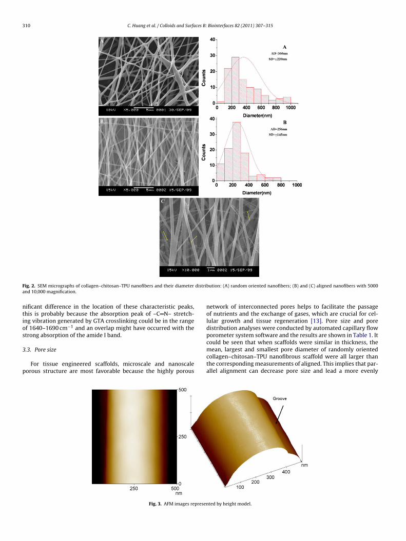
To observe the surface morphologies of collagen–chitosan–TPUnanofibers, atomic-force microscopy (AFM) was employed by usingheight mode (Fig. 3). It was reported that the surface of electrospuncollagen fibers was comparatively rougher than that of electrospunsynthetic polymers [26], whereas from our AFM images, with a TPUproportion of 25% it could be clearly observed that the surface ofcollagen–chitosan–TPU nanofibers was quite smooth and a grooveon the right side of the fiber could be found. This phenomenonmight be attributed to the complexity of mixture solution whilethe grooves were not found on all the fibers. From surface mor-phology images we can see that TPU component could improve thespinnability of polymer solution while the existence of grooves onsome nanofibers would be conducive to cell adhesion and prolifer-ation by providing adhesion sites for cell growth.
With the aim of measuring fiber alignment, a two-dimensionalfast Fourier transform (2D FFT) approach described by Ayres et al.[25] was adapted. In brief, a quadrate region was captured fromSEM images (Fig. 4A and B) and then analyzed with ImageJ soft-ware to create corresponding frequency plots and 2D FFT alignmentplots. The two peaks at 175◦ and 355◦ in Fig. 4E show that witha rotation speed of 4000 r/min, pure TPU nanofibers were highlyarrayed along one direction, however, in the three-material basedsystem (Fig. 4F), fiber orientation could not be regulated with sucha high uniformity. Although two main peaks could also be foundat 5◦ and 185◦, the existence of other peaks indicates that somenanofibers are not well aligned. This phenomenon demonstratesthat besides ambient parameters such as applied voltage and rotat-ing speed, properties of mixture solution (difference in molecularweight and electric-charge number) also play an indispensable rolein the determination of fiber morphology.
3.2. Fourier transform infrared spectroscopy
In a complicated system containing three types of materials, theFourier transform infrared spectroscopy (FTIR) could be used asan effective method to define the existence of each component.FTIR spectra of electrospun collagen–chitosan and collagen–TPUnanofibers were studied in previous work [8,26]. Fig. 5 depicted theFTIR spectra of non-crosslinked (Fig. 5a) and crosslinked (Fig. 5b)collagen–chitosan–TPU fibers with a weight ratio of 60%:15%:25%(collagen:chitosan:TPU).
As shown in Fig. 5a, the characteristic absorption bands of col-lagen were observed at 1650 cm−1 (amide I), 1530 cm−1 (amide II),
1200 cm−1 (amide III), respectively while the peak at 1130 cm−1was assigned to chitosan for its saccharine structure. N–H andC–H stretches at 2940 cm−1 and 3300 cm−1 and other peaks over-lapped with collagen between 1530 cm−1 and 1200 cm−1 werecharacteristic of TPU. Compared to Fig. 5a, Fig. 5b showed no sig-
310 C. Huang et al. / Colloids and Surfaces B: Biointerfaces 82 (2011) 307–315
F distria
ntios
3
p
ig. 2. SEM micrographs of collagen–chitosan–TPU nanofibers and their diameternd 10,000 magnification.
ificant difference in the location of these characteristic peaks,his is probably because the absorption peak of –C N– stretch-ng vibration generated by GTA crosslinking could be in the rangef 1640–1690 cm−1 and an overlap might have occurred with thetrong absorption of the amide I band.
.3. Pore size
For tissue engineered scaffolds, microscale and nanoscaleorous structure are most favorable because the highly porous
Fig. 3. AFM images represen
bution: (A) random oriented nanofibers; (B) and (C) aligned nanofibers with 5000
network of interconnected pores helps to facilitate the passageof nutrients and the exchange of gases, which are crucial for cel-lular growth and tissue regeneration [13]. Pore size and poredistribution analyses were conducted by automated capillary flowporometer system software and the results are shown in Table 1. It
could be seen that when scaffolds were similar in thickness, themean, largest and smallest pore diameter of randomly orientedcollagen–chitosan–TPU nanofibrous scaffold were all larger thanthe corresponding measurements of aligned. This implies that par-allel alignment can decrease pore size and lead a more evenlyted by height model.

C. Huang et al. / Colloids and Surfaces B: Biointerfaces 82 (2011) 307–315 311
Fig. 4. SEM images of aligned electrospun scaffolds with a rotation speed of 4000 r/minnanofibers). ImageJ frequency plots (C and D) and 2D FFT alignment plots (E and F) for th
Fm
pGpa
3
vsn
TP
ig. 5. FTIR spectra of coaxial collagen–chitosan–TPU electrospun nanofibrousembranes. Non-crosslinked (a); crosslinked (b).
ore-size distribution. What is more, we can conclude that afterTA vapor crosslinking, nanofibrous scaffolds become more com-act because specimen thickness and pore size of both random andligned scaffolds decreased dramatically.
.4. Mechanical properties analysis
In the fabrication of tubular scaffolds, mechanical strength is ofital importance to provide enough support and this is the rea-on why natural materials, such as collagen and chitosan couldot be used as the dominant component for electrospun grafts.
able 1ore diameter of randomly oriented and aligned collagen–chitosan–TPU nanofibrous scaf
Collagen–chitosan–TPUnanofibrous scaffolds
Specimenthickness (mm)
Mean flowdiameter ±
AlignedNon-crosslinked 0.108 0.2562 ± 0Crosslinked 0.088 0.1002 ± 0
Randomly orientedNon-crosslinked 0.115 0.3745 ± 0Crosslinked 0.105 0.2447 ± 0
((A) represents pure TPU nanofibers while (B) represents collagen–chitosan–TPUe corresponding quadrate regions.
It is reported that the tensile strength of a native artery is about1.5 MPa [1], however, for scaffolds made from natural materials, amuch higher strength is necessary when aspects like degradationand wet-strength loss are taken into consideration.
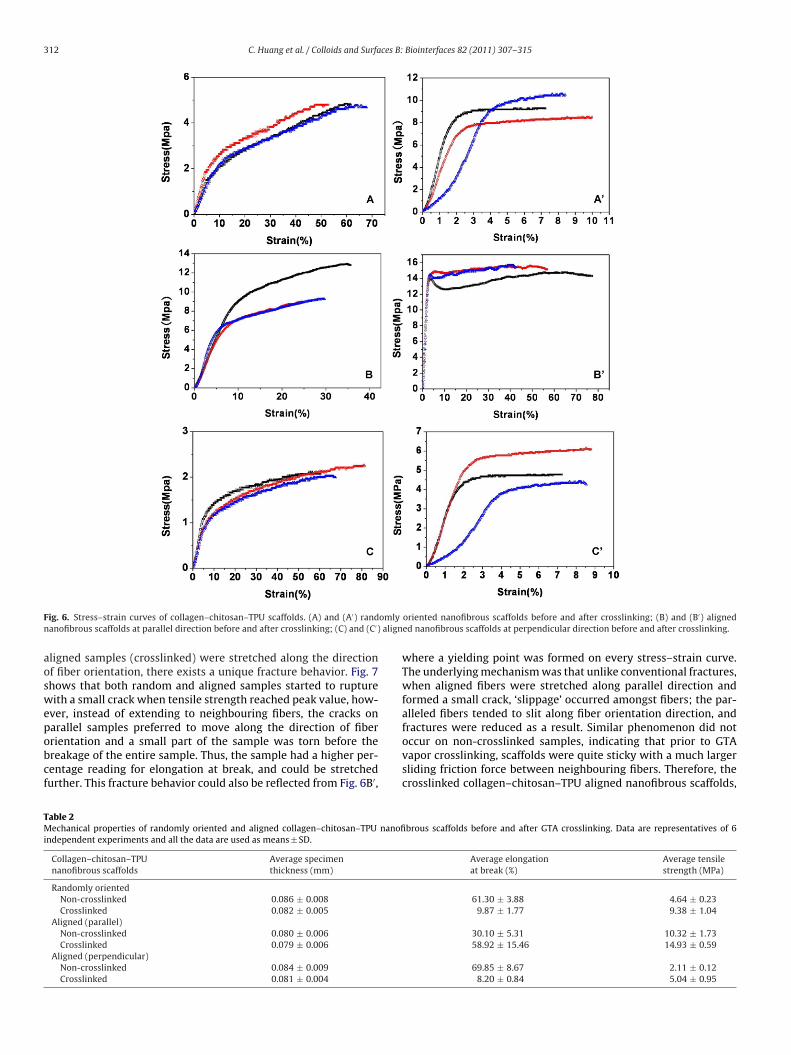
The typical tensile stress–strain curves of random orientedand aligned collagen–chitosan–TPU nanofibrous scaffolds (non-crosslinked, crosslinked) are shown in Fig. 6 while the averageelongation at break and average tensile strength of each specimenare summarized in Table 2. Comparing Fig. 6A–C with Fig. 6A′–C′, itcan be seen that GTA vapor crosslinking had a positive influence ontensile strength but a negative influence on average elongation atbreak. After crosslinking both randomly oriented and aligned scaf-folds were tended to be more stiff and brittle. To improve elasticityof scaffold, TPU was added to natural fibers, such as collagen andchitosan. TPU proportion of 10%, 20%, 25% and 30% were investi-gated to determine the optimal component ratio. According to ourobservation, blended fibrous scaffolds with TPU proportion lowerthan 20% would be easily broken when squeezed or stretched,making them too fragile for tubular applications. Therefore, TPUproportion should not be set below 25% otherwise the elongationat break of crosslinked scaffolds could not exceed 10% and the scaf-folds were too fragile to meet the flexibility requirements of tubulargrafts.
The tensile strength of the aligned nanofibrous scaffolds showedsignificant differences between parallel (14.93 ± 0.59 MPa) andperpendicular (5.04 ± 0.95 MPa) directions. Moreover, comparisonof elongation at break between scaffolds of parallel and perpendic-
ular alignment showed an even sharper difference (58.92 ± 15.46%as opposed to 8.20 ± 0.84%).As described before, GTA crosslinking had a negative effect onelongation at break, whereas at parallel direction crosslinked scaf-folds boasted better elasticity than non-crosslinked ones. While
folds.
poreSD (�m)
Largest porediameter (�m)
Smallest porediameter (�m)
.0872 0.6032 0.1796
.0197 0.1743 0.0711
.1084 0.8119 0.279
.1414 0.3185 0.0823
312 C. Huang et al. / Colloids and Surfaces B: Biointerfaces 82 (2011) 307–315
F omlyn align
aoswepobcf
TMi
ig. 6. Stress–strain curves of collagen–chitosan–TPU scaffolds. (A) and (A′) randanofibrous scaffolds at parallel direction before and after crosslinking; (C) and (C′)
ligned samples (crosslinked) were stretched along the directionf fiber orientation, there exists a unique fracture behavior. Fig. 7hows that both random and aligned samples started to ruptureith a small crack when tensile strength reached peak value, how-
ver, instead of extending to neighbouring fibers, the cracks on
arallel samples preferred to move along the direction of fiberrientation and a small part of the sample was torn before thereakage of the entire sample. Thus, the sample had a higher per-entage reading for elongation at break, and could be stretchedurther. This fracture behavior could also be reflected from Fig. 6B′,able 2echanical properties of randomly oriented and aligned collagen–chitosan–TPU nanofi
ndependent experiments and all the data are used as means ± SD.
Collagen–chitosan–TPUnanofibrous scaffolds
Average specimenthickness (mm)
Randomly orientedNon-crosslinked 0.086 ± 0.008Crosslinked 0.082 ± 0.005
Aligned (parallel)Non-crosslinked 0.080 ± 0.006Crosslinked 0.079 ± 0.006
Aligned (perpendicular)Non-crosslinked 0.084 ± 0.009Crosslinked 0.081 ± 0.004
oriented nanofibrous scaffolds before and after crosslinking; (B) and (B′) aligneded nanofibrous scaffolds at perpendicular direction before and after crosslinking.
where a yielding point was formed on every stress–strain curve.The underlying mechanism was that unlike conventional fractures,when aligned fibers were stretched along parallel direction andformed a small crack, ‘slippage’ occurred amongst fibers; the par-alleled fibers tended to slit along fiber orientation direction, and
fractures were reduced as a result. Similar phenomenon did notoccur on non-crosslinked samples, indicating that prior to GTAvapor crosslinking, scaffolds were quite sticky with a much largersliding friction force between neighbouring fibers. Therefore, thecrosslinked collagen–chitosan–TPU aligned nanofibrous scaffolds,brous scaffolds before and after GTA crosslinking. Data are representatives of 6
Average elongationat break (%)
Average tensilestrength (MPa)
61.30 ± 3.88 4.64 ± 0.239.87 ± 1.77 9.38 ± 1.04
30.10 ± 5.31 10.32 ± 1.7358.92 ± 15.46 14.93 ± 0.59
69.85 ± 8.67 2.11 ± 0.128.20 ± 0.84 5.04 ± 0.95
C. Huang et al. / Colloids and Surfaces B:
F
wwc
3
ra[s1ptMsbfmIot
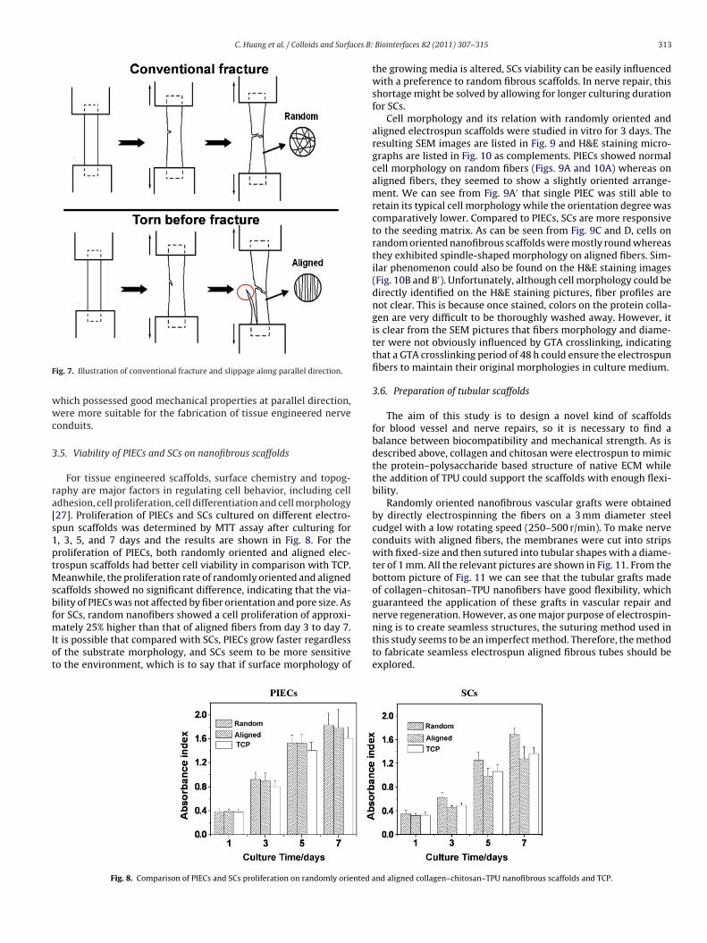
ig. 7. Illustration of conventional fracture and slippage along parallel direction.
hich possessed good mechanical properties at parallel direction,ere more suitable for the fabrication of tissue engineered nerve
onduits.
.5. Viability of PIECs and SCs on nanofibrous scaffolds
For tissue engineered scaffolds, surface chemistry and topog-aphy are major factors in regulating cell behavior, including celldhesion, cell proliferation, cell differentiation and cell morphology27]. Proliferation of PIECs and SCs cultured on different electro-pun scaffolds was determined by MTT assay after culturing for, 3, 5, and 7 days and the results are shown in Fig. 8. For theroliferation of PIECs, both randomly oriented and aligned elec-rospun scaffolds had better cell viability in comparison with TCP.
eanwhile, the proliferation rate of randomly oriented and alignedcaffolds showed no significant difference, indicating that the via-ility of PIECs was not affected by fiber orientation and pore size. As
or SCs, random nanofibers showed a cell proliferation of approxi-ately 25% higher than that of aligned fibers from day 3 to day 7.t is possible that compared with SCs, PIECs grow faster regardlessf the substrate morphology, and SCs seem to be more sensitiveo the environment, which is to say that if surface morphology of
Fig. 8. Comparison of PIECs and SCs proliferation on randomly oriented a
Biointerfaces 82 (2011) 307–315 313
the growing media is altered, SCs viability can be easily influencedwith a preference to random fibrous scaffolds. In nerve repair, thisshortage might be solved by allowing for longer culturing durationfor SCs.
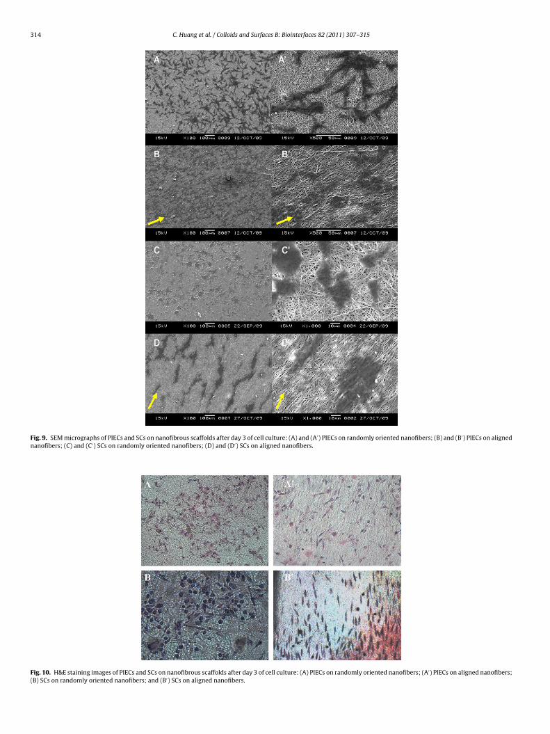
Cell morphology and its relation with randomly oriented andaligned electrospun scaffolds were studied in vitro for 3 days. Theresulting SEM images are listed in Fig. 9 and H&E staining micro-graphs are listed in Fig. 10 as complements. PIECs showed normalcell morphology on random fibers (Figs. 9A and 10A) whereas onaligned fibers, they seemed to show a slightly oriented arrange-ment. We can see from Fig. 9A′ that single PIEC was still able toretain its typical cell morphology while the orientation degree wascomparatively lower. Compared to PIECs, SCs are more responsiveto the seeding matrix. As can be seen from Fig. 9C and D, cells onrandom oriented nanofibrous scaffolds were mostly round whereasthey exhibited spindle-shaped morphology on aligned fibers. Sim-ilar phenomenon could also be found on the H&E staining images(Fig. 10B and B′). Unfortunately, although cell morphology could bedirectly identified on the H&E staining pictures, fiber profiles arenot clear. This is because once stained, colors on the protein colla-gen are very difficult to be thoroughly washed away. However, itis clear from the SEM pictures that fibers morphology and diame-ter were not obviously influenced by GTA crosslinking, indicatingthat a GTA crosslinking period of 48 h could ensure the electrospunfibers to maintain their original morphologies in culture medium.
3.6. Preparation of tubular scaffolds
The aim of this study is to design a novel kind of scaffoldsfor blood vessel and nerve repairs, so it is necessary to find abalance between biocompatibility and mechanical strength. As isdescribed above, collagen and chitosan were electrospun to mimicthe protein–polysaccharide based structure of native ECM whilethe addition of TPU could support the scaffolds with enough flexi-bility.
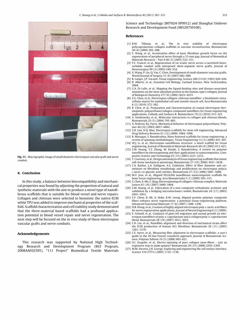
Randomly oriented nanofibrous vascular grafts were obtainedby directly electrospinning the fibers on a 3 mm diameter steelcudgel with a low rotating speed (250–500 r/min). To make nerveconduits with aligned fibers, the membranes were cut into stripswith fixed-size and then sutured into tubular shapes with a diame-ter of 1 mm. All the relevant pictures are shown in Fig. 11. From thebottom picture of Fig. 11 we can see that the tubular grafts madeof collagen–chitosan–TPU nanofibers have good flexibility, whichguaranteed the application of these grafts in vascular repair and
nerve regeneration. However, as one major purpose of electrospin-ning is to create seamless structures, the suturing method used inthis study seems to be an imperfect method. Therefore, the methodto fabricate seamless electrospun aligned fibrous tubes should beexplored.nd aligned collagen–chitosan–TPU nanofibrous scaffolds and TCP.
314 C. Huang et al. / Colloids and Surfaces B: Biointerfaces 82 (2011) 307–315
Fig. 9. SEM micrographs of PIECs and SCs on nanofibrous scaffolds after day 3 of cell culture: (A) and (A′) PIECs on randomly oriented nanofibers; (B) and (B′) PIECs on alignednanofibers; (C) and (C′) SCs on randomly oriented nanofibers; (D) and (D′) SCs on aligned nanofibers.
Fig. 10. H&E staining images of PIECs and SCs on nanofibrous scaffolds after day 3 of cell culture: (A) PIECs on randomly oriented nanofibers; (A′) PIECs on aligned nanofibers;(B) SCs on randomly oriented nanofibers; and (B′) SCs on aligned nanofibers.
C. Huang et al. / Colloids and Surfaces B:
Fc
4
csbCwfttnv
A
o2
[
[
[
[
[
[
[
[
[
[
[
[
[
[
[
ig. 11. Macrographic image of small diameter electrospun vascular graft and nerveonduit.
. Conclusion
In this study, a balance between biocompatibility and mechani-al properties was found by adjusting the proportion of natural andynthetic materials with the aim to produce a novel type of nanofi-rous scaffolds that is suitable for blood vessel and nerve repairs.ollagen and chitosan were selected to biomimic the native ECMhile TPU was added to improve mechanical properties of the scaf-
old. Scaffold characterization and cell viability study demonstratedhat the three-material based scaffolds had a profound applica-ion potential in blood vessel repair and nerve regeneration. Theext step will be focused on the in vivo study of these electrospunascular grafts and nerve conduits.
cknowledgements
This research was supported by National High Technol-gy Research and Development Program (863 Program,008AA03Z305), “111 Project” Biomedical Textile Materials
[
[
[
Biointerfaces 82 (2011) 307–315 315
Science and Technology (B07024-SP0912) and Shanghai UnileverResearch and Development Fund (08520750100).
References
[1] B.W. Tillman, et al., The in vivo stability of electrospunpolycaprolactone–collagen scaffolds in vascular reconstruction, Biomaterials30 (4) (2009) 583–588.
[2] S. Wang, et al., Acceleration effect of basic fibroblast growth factor on theregeneration of peripheral nerve through a 15-mm gap, Journal of BiomedicalMaterials Research – Part A 66 (3) (2003) 522–531.
[3] P.C. Francel, et al., Regeneration of rat sciatic nerve across a LactoSorb biore-sorbable conduit with interposed short-segment nerve grafts, Journal ofNeurosurgery 99 (3) (2003) 549–554.
[4] X. Wang, P. Lin, Q. Yao, C. Chen, Development of small-diameter vascular grafts,World Journal of Surgery 31 (4) (2007) 682–689.
[5] R. Langer, J.P. Vacanti, Tissue engineering, Science 260 (5110) (1993) 920–926.[6] B. Alberts, et al., Essential Cell Biology, Garland Science, New York/London,
2004.[7] G.A. Di Lullo, et al., Mapping the ligand-binding sites and disease-associated
mutations on the most abundant protein in the human, type I collagen, Journalof Biological Chemistry 277 (6) (2002) 4223–4231.
[8] Z.G. Chen, et al., Electrospun collagen–chitosan nanofiber: a biomimetic extra-cellular matrix for endothelial cell and smooth muscle cell, Acta Biomaterialia6 (2) (2010) 372–382.
[9] R. Chen, et al., Preparation and characterization of coaxial electrospun ther-moplastic polyurethane/collagen compound nanofibers for tissue engineeringapplications, Colloids and Surfaces B: Biointerfaces 79 (2) (2010) 315–325.
10] A. Sionkowska, et al., Molecular interactions in collagen and chitosan blends,Biomaterials 25 (5) (2004) 795–801.
11] A. Pedicini, R.J. Farris, Mechanical behavior of electrospun polyurethane, Poly-mer 44 (22) (2003) 6857–6862.
12] S.H. Lim, H.Q. Mao, Electrospun scaffolds for stem cell engineering, AdvancedDrug Delivery Reviews 61 (12) (2009) 1084–1096.
13] R. Murugan, S. Ramakrishna, Nano-featured scaffolds for tissue engineering: areview of spinning methodologies, Tissue Engineering 12 (3) (2006) 435–447.
14] W.J. Li, et al., Electrospun nanofibrous structure: a novel scaffold for tissueengineering, Journal of Biomedical Materials Research 60 (4) (2002) 613–621.
15] Z.M. Huang, Y.Z. Zhang, M. Kotaki, S. Ramakrishna, A review on polymernanofibers by electrospinning and their applications in nanocomposites, Com-posites Science and Technology 63 (15) (2003) 2223–2253.
16] T. Courtney, et al., Design and analysis of tissue engineering scaffolds that mimicsoft tissue mechanical anisotropy, Biomaterials 27 (19) (2006) 3631–3638.
17] C.A. Bashur, L.A. Dahlgren, A.S. Goldstein, Effect of fiber diameter and ori-entation on fibroblast morphology and proliferation on electrospun poly(d,l-lactic-co-glycolic acid) meshes, Biomaterials 27 (33) (2006) 5681–5688.
18] M.V. Jose, et al., Aligned PLGA/HA nanofibrous nanocomposite scaffolds forbone tissue engineering, Acta Biomaterialia 5 (1) (2009) 305–315.
19] Z. Chen, X. Mo, F. Qing, Electrospinning of collagen–chitosan complex, MaterialsLetters 61 (16) (2007) 3490–3494.
20] Z.M. Huang, et al., Fabrication of a new composite orthodontic archwire andvalidation by a bridging micromechanics model, Biomaterials 24 (17) (2003)2941–2953.
21] S.Y. Chew, R. Mi, A. Hoke, K.W. Leong, Aligned protein–polymer compositefibers enhance nerve regeneration: a potential tissue-engineering platform,Advanced Functional Materials 17 (8) (2007) 1288–1296.
22] H.B. Wang, et al., Creation of highly aligned electrospun poly-l-lactic acid fibersfor nerve regeneration applications, Journal of Neural Engineering 6 (1) (2009).
23] E. Schnell, et al., Guidance of glial cell migration and axonal growth on elec-trospun nanofibers of poly-�-caprolactone and a collagen/poly-�-caprolactoneblend, Biomaterials 28 (19) (2007) 3012–3025.
24] C.H. Lee, et al., Nanofiber alignment and direction of mechanical strain affectthe ECM production of human ACL fibroblast, Biomaterials 26 (11) (2005)1261–1270.
25] C.E. Ayres, et al., Measuring fiber alignment in electrospun scaffolds: a user’s
guide to the 2D fast Fourier transform approach, Journal of Biomaterials Sci-ence, Polymer Edition 19 (5) (2008) 603–621.26] D.I. Zeugolis, et al., Electro-spinning of pure collagen nano-fibres – just anexpensive way to make gelatin? Biomaterials 29 (15) (2008) 2293–2305.
27] M.M. Stevens, J.H. George, Exploring and engineering the cell surface interface,Science 310 (5751) (2005) 1135–1138.
Copyright © 2022 FDOKUMEN