SYNTHESIS, SELF-ASSEMBLY AND PROPERTIES OF ZnO ...
210
SYNTHESIS, SELF-ASSEMBLY AND PROPERTIES OF ZnO-RELATED NANOSTRUCTURES AND NANOCOMPOSITES YAO KE XIN NATIONAL UNIVERSITY OF SINGAPORE 2008
-
Upload
khangminh22 -
Category
Documents
-
view
3 -
download
0
Transcript of SYNTHESIS, SELF-ASSEMBLY AND PROPERTIES OF ZnO ...

SYNTHESIS, SELF-ASSEMBLY AND PROPERTIES
OF ZnO-RELATED NANOSTRUCTURES AND
NANOCOMPOSITES
YAO KE XIN
NATIONAL UNIVERSITY OF SINGAPORE
2008

SYNTHESIS, SELF-ASSEMBLY AND PROPERTIES
OF ZnO-RELATED NANOSTRUCTURES AND
NANOCOMPOSITES
YAO KE XIN
(M. ENG., TIANJIN UNIVERSITY, P. R. CHINA)
A THESIS SUBMITTED
FOR THE DEGREE OF DOCTOR OF PHILOSOPHY
DEPARTMENT OF CHEMICAL & BIOMOLECULAR ENGINEERING
NATIONAL UNIVERSITY OF SINGAPORE
2008

I
ACKNOWLEDGEMENTS
I would like to express my deep and sincere appreciation to my supervisor, Professor Zeng
Hua Chun. His wide knowledge and his logical way of thinking have been of great value for
me. His understanding, encouraging and personal guidance have provided a good basis for the
present thesis.
I warmly thank Liu Bin, Li Jing, Zhang Yu Xin and Wang Dan Ping for their valuable advice
and friendly help. Their extensive discussions around my work and interesting explorations in
operations have been very helpful for this study.
I am very thankful to Ms. Khoh Leng Khim, Mr. Mao Ning, Mr. Chia Phai Ann, Dr. Yuan Ze
Liang, Ms. Lee Chai Keng, Mdm. Sam Fam Hwee Koong, Ms. Tay Choon Yen, and Mr. Shang
Zhen Hua for their technical and kind support.
I owe my loving thanks to my wife Shang Ying, my son Yao Lu Qi, my parents and my sisters.
They have lost a lot due to my research abroad. Without their encouragement and
understanding it would have been impossible for me to finish this work.
The financial support of National University of Singapore is gratefully acknowledged.

II
TABLE OF CONTENTS
ACKNOWLEDGEMENTS··········································································································I
TABLE OF CONTENTS·············································································································II
SUMMARY·······················································································································VI
SYMBOLS AND ABBREVIATIONS····················································································VIII
LIST OF TABLES······················································································································X
LIST OF FIGURES····················································································································XI
PUBLICATIONS RELATED TO THE THESIS····························································XVIII
CHAPTER 1 INTRODUCTION··································································································1
1.1 Overview·······················································································································1
1.2 Objectives and Scope····································································································2
1.3 Structure of the Thesis···································································································3
References·····························································································································5
CHAPTER 2 LITERATURE REVIEW·······················································································6
2.1 Introduction of Synthetic Methods to Produce Nanomaterials········································6
2.1.1 Vapor-Phase Synthesis··························································································6
2.1.2 Template-Directed Synthesis·····················································································7
2.1.3 Hydrothermal/Solvothermal Synthesis······································································7
2.1.4 Microemulsion Synthesis··························································································8
2.1.5 Sol-gel Synthesis·······································································································9
2.1.6 Microwave and Ultrasonic Synthesis········································································9
2.2 Review of ZnO Nanomaterial Synthesis········································································10
2.2.1 ZnO Crystal Structures··························································································10
2.2.2 Growth of ZnO Nanomaterials in Vapor Phase·······················································13
2.2.3 Growth of ZnO Nanomaterials in Liquid Phase······················································16
2.2.3.1 Hydrothermal/Solvothermal Synthesis······························································16
2.2.3.2 Microemulsion··························································································18
2.3 Review of Cobalt Oxide Nanomaterial Synthesis·············································20

III
2.3.1 Cobalt Oxide Crystal Structures··············································································20
2.3.2 Cobalt Oxide Synthesis··························································································21
2.4 Review of Nanocomposite Synthesis and Properties·····················································24
2.4.1 Metal Oxide/Metal Oxide Composites····································································25
2.4.2 Carbon Nanotube Composites·················································································27
2.4.3 Metal Oxide/Polymer Composites···········································································28
2.5 Nanomaterial Application····················································································31
2.5.1 Surface Modification·······························································································31
2.5.2 Catalytic Applications····················································································34
References ···························································································································38
CHAPTER 3 CHARACTERIZATION METHODS·································································53
3.1 Powder X-Ray Diffraction (XRD) ················································································53
3.2 Scanning Electron Microscopy (SEM)/Field Emission Scanning Electron Microscopy
(FESEM)/Energy-Dispersive X-Ray Spectroscopy (EDX) ·········································53
3.3 X-Ray Photoelectron Spectroscopy (XPS) ································································54
3.4 Transmission Electron Microscopy (TEM)/High-Resolution Transmission Electron
Microscopy (HRTEM)/Selected Area Electron Diffraction (SAED) ··························54
3.5 Fourier-Transform Infrared Spectroscopy (FTIR) ························································54
3.6 Thermogravimetry Analysis (TGA) ·············································································55
3.7 UV-vis Analysis·············································································································55
3.8 Brunauer-Emmett-Teller (BET) Measurement······························································55
3.9 Contact Angle Measurement························································································56
CHAPTER 4 ASYMMETRIC ZnO NANOSTRUCTURES WITH AN INTERIOR
CAVITY···········································································································57
4.1 Introduction·············································································································57
4.2 Experimental Section·····································································································60
4.3 Result and Discussion···································································································60
4.3.1 Structural and Compositional Characterization·······················································60

IV
4.3.2 Asymmetric Nanostructures····················································································61
4.3.3 Formation Mechanism ····························································································66
4.3.4 Structural Features and Their Implications······························································69
4.3.5 One-Dimensional Extension Modes········································································71
4.4 Conclusions···················································································································73
References····························································································································75
CHAPTER 5 SYMMETRIC LINEAR ASSEMBLY OF HOURGLASS-LIKE ZnO
NANOSTRUCTURES·····················································································78
5.1 Introduction···················································································································78
5.2 Experimental Section····································································································82
5.3 Results and Discussion··································································································82
5.3.1 Synthesis and Characterization················································································82
5.3.2 Complex Nanostructures and Linear Assemblies····················································84
5.3.3 Causes of Linear Assembly·····················································································89
5.3.4 Growth Mechanism·································································································93
5.4 Conclusions·················································································································95
References··························································································································97
CHAPTER 6 ZnO/PVP NANOCOMPOSITE SPHERES WITH TWO HEMISPHERES·····104
6.1 Introduction···········································································································104
6.2 Experimental Section···································································································106
6.3 Results and Discussion························································································108
6.4 Conclusions········································································································118
References··························································································································119
CHAPTER 7 SYNTHETIC ARCHITECTURES OF CoO/ZnO AND Zn1−XCoXO/Co1−YZnYO
NANOCOMPOSITES·······················································································122
7.1 Introduction················································································································122
7.2 Experimental Section··································································································124
7.2.1 Pure CoO Nanoparticles························································································124

V
7.2.2 CoO/ZnO Core/Shell Nanocomposites······························································125
7.2.3 Zn1−xCoxO/Co1−yZny(OH)2 and Zn1−xCoxO/Co1−yZnyO Nanocomposites··············125
7.2.4 CO Oxidation Reaction·························································································126
7.3 Results and Discussion·······························································································130
7.4 Conclusions·············································································································152
References··························································································································154
CHAPTER 8 NANOCOMPOSITE FILMS OF SAM/Pt/ZnO/SiO2 WITH TUNABLE
WETTABILITY BETWEEN SUPERHYDROPHILICITY AND
SUPERHYDROPHOBICITY········································································158
8.1 Introduction················································································································158
8.2 Experimental Section··································································································161
8.2.1 Synthesis of Zinc Carbonate Hydroxide································································161
8.2.2 Synthesis of Zinc Hydroxide Netlike Film on Glass Slides··································161
8.2.3 Preparation of Nanostructured ZnO/SiO2 Films····················································161
8.2.4 Coating of Pt Nanoparticles onto the ZnO/SiO2 Films··········································162
8.2.5 Modification with DT and MPA········································································162
8.2.6 Removal of DT and MPA······················································································162
8.3 Results and Discussion·······························································································163
8.4 Conclusions················································································································179
References··························································································································181
CHAPTER 9 OVERALL CONCLUSIONS AND RECOMMENDATIONS FOR FUTURE
WORK··············································································································185
9.1 Overall Conclusions····································································································185
9.2 Recommendations for Future Work············································································188

VI
SUMMARY
Very recently, nanostructured materials have attracted a great deal of attention from researchers
in various fields for both their fundamental size-dependent properties and their many important
technological applications. Intensive research efforts have been focused on the synthesis of
well-defined uniformly sized nanomaterials in order to identify their size-dependent properties.
Among these materials, ZnO nanomaterials have been one of the most intensively studied
owing to their versatile properties and applications.
This thesis mainly focuses on synthesis, self-assembly and properties of ZnO-related
nanostructures and nanocomposites. In this thesis, there are nine chapters systematically
describing synthesis, characterization and application of ZnO nanomaterials. Asymmetric
ZnO nanostructures with an interior cavity are firstly discussed. It has been found that the
created interior space is located in the upper part of the nanostructures contrast to normal
central hollow interior, showing a new type of structural anisotropy. The formation mechanism
has been proposed that Tween-85 surfactant might regulate self-assembly of primary
nanocrystallites and growth of two or more sets of crystal planes to form such ZnO asymmetric
nanostructures.
Secondly, symmetric linear assembly of hourglass-like ZnO nanostructures has been
obtained via hydrothermal approach. With the assistance of Tween-85 surfactant, special shape
of ZnO subunits and their self-assembly has been work out. After characterization, it is found
that the linear assembly of hour-glass structures is attributed to inter-connection of subunits
through van der Waals interaction of their surface-anchored alkylated oleate groups.

VII
Meanwhile, the finding in this system also demonstrates that the formation of hollow interior
space results from an Ostwald ripening process.
Thirdly, ZnO/PVP nanocomposite spheres with two hemispheres have been investigated.
For the first time we have demonstrated that noncentrosymmetric ZnO can be prepared into
symmetric spheres by coupling two mesocrystalline hemispheres in which PVP is incorporated
as a secondary phase, that is, forming ZnO/PVP nanocomposites. This synthetic method
displays new possibilities of morphological and compositional control, property engineering,
and structural organization for hybrid inorganic-organic materials, including self-assembled
composite thin films.
Fourthly, synthetic architectures of CoO/ZnO and Zn1−xCoxO/Co1−yZnyO nanocomposites
have been studied by multi-pot and one-pot approaches. Compared to one-pot approach,
multi-pot approach can obtain a CoO/ZnO nanocomposite with individual pure phases and
avoid inter-diffusion of metal ions. In addition to nanocomposite synthesis, catalytic properties
of the composites have been characterized by CO oxidation at various reaction temperatures.
Finally, nanocomposite films of SAM/Pt/ZnO/SiO2 with tunable wettability between
superhydrophilicity and superhydrophobicity have been examined. The wettability of
nanocomposite films is characterized by contact angles of DI water, showing that ZnO/SiO2
and Pt/ZnO/SiO2 films are superhydrophilic and hydrophilic, respectively. After introducing
self-assembled monolayers (SAMs), organic-inorganic hybrid films of SAM/Pt/ZnO/SiO2
show a controllable wettability between hydrophilicity and hydrophobicity via tuning the
composition of SAMs. Furthermore, nanocomposite films show potential applications in
chemical sensors and small scale water transportation.

VIII
SYMBOLS AND ABBREVIATIONS
Symbols
d Interlay space
Eg Band gap energy
e- -Electron
eV Electron volt
fcc - Face-center cubic
vas Asymmetric vibrational mode
vs - Symmetric vibrational mode
δ+ Positive charge
δ- - Negative charge
λ Wavelength of X-ray radiation
θ Diffraction angle
Abbreviations
AFM Atomic Force Microscopy
AuNP Gold Nanoparticle
BE Binding Energy
BET Brunauer-Emmett-Teller
BJH Barret-Joyner-Halenda
CNT Carbon Nanotube
CTAB Cetyltrimethylammonium Bromide

IX
DrTGA Differential Thermalgravimetry Analysis
DT Dodecanethiol
EDA Ethylenediamine
EDX Energy-Disperse X-ray
FESEM Field-Emission Scanning Electron Microscopy
FTIR Fourier Transform Infrared
H Hour
HRTEM High-Resolution Transmission Electron Microscopy
MPA Mercaptopropionic Acid
PVP Polyvinylpyrrolidone
SAM Self-Assembled Monolayer
SEM Scanning Electron Microscopy
SDS Sodium Dodecyl Sulfate
TEM Transmission Electron Microscopy
XPS X-ray Photoelectron Spectroscopy
XRD X-ray Diffraction
ZB Zinc Blende
0,1,2,3D 0,1,2,3 Dimensional

X
LIST OF TABLES
Table 6-1 Detailed experimental descriptions for synthesis of ZnO spheres···························107
Table 6-2 XPS results for PVP and ZnO/PVP spheres··························································114
Table 7-1 Preparation details and for the samples reported··················································129
Table 7-2 Summaries of nanocomposites synthesized in this work and their metal ions relative
populations···············································································································142

XI
LIST OF FIGURES
Figure 2-1 Schematic illustrations of template-directed synthesis (a) the formation of
nanowires and nanotubes by filling and partial filling the pores within a porous membrane with the desired materials or a precursor to this material; (b) the formation of nanowires/nanotubes by internally/externally templating against structures self-assembled from surfactant molecules··········································7
Figure 2-2 Stick and ball representation of ZnO crystal structures: (a) cubic rocksalt (B1); (b) cubic zinc blende (B3); and (c)(d) hexagonal wurtzite (B4) ·························11
Figure 2-3 A schematic diagram of the experimental apparatus for growth of ZnO nanostructures by the solid-vapor phase process··············································14
Figure 2-4 A collection of nanostructures of ZnO synthesized under controlled conditions by thermal evaporation of solid powders···························································14
Figure 2-5 Stick and ball representation of CoxOy crystal structures: (a) CoO and (b) Co3O4···················································································································21
Figure 4-1 (a-c) Symmetric geometrical structures: cube, sphere, and tetragonal bar, where symmetric planes can be found in all principal directions. (d, e) Asymmetric geometrical structures: cone and truncated cone, where there is no symmetric plane between the top and the cone base··························································58
Figure 4-2 (a) Structure and formation of bullet-head-like hollow structures of ZnO in solution; (b) molecular structure of Tween-85; (c) a representative XRD pattern of the ZnO hollow structures prepared in this work···········································61
Figure 4-3 TEM images representative of the bullet-head-like ZnO hollow structure at different sizes and magnifications, where the interior cavity of the structures is also clearly demonstrated. Note that most of the ZnO nanostructures in these images are shown with their trapezoidal side view. The reaction time in this synthesis was set at 4 h·······················································································62
Figure 4-4 FESEM images of exterior surface morphologies of the bullet-head-like ZnO hollow structures: (a) overall crystal uniformity; (b) trapezoidal side view (the white arrow indicates a side plane of (10-10)); (c) hexagonal bottom view (the white arrow points to a spiral step on the plane of (000-1)). The reaction time in this synthesis was set at 4 h················································································64
Figure 4-5 (a) Comparison of exterior crystal morphology between a well-faceted ZnO

XII
structure and a bullet-head-like ZnO viewed along the [0001] axis; (b) HRTEM image of a bullet-head-like ZnO hollow structure taken along the [0001] axis (i.e., hexagonal topview); (c) a bullet-head-like ZnO hollow structure viewed along the [0001] axis and its related SAED pattern ([0001] zone diffraction spots) ··················································································································65
Figure 4-6 TEM images for the formation process: (a) ZnO hollow structures together with their solid precursor Zn(OH)2 (thin-layer-like); (b) fragments of ZnO-based crystals; (c) a ring-like base formed by attachment of ZnO nanocrystals together with residual Zn(OH)2; (d) a bullet-head-like ZnO hollow structure. Note that to observe this initial state of ZnO growth the reaction time in this synthesis was set at only 1 h under the same conditions of the samples in Figures 4-3 and 4-4·······················································································································67
Figure 4-7 (a) Formation process of the hollow structures via "oriented attachment" (cross-sectional side view): (i) a ring-like hexagonal base, (ii) a complete base and deposition/growth of sloped walls, (iii) continuous deposition/growth of the walls and base, and (iv) top closure. The deposition/growth rate of nanocrystallites along [0001] is denoted by the length of the arrows. (b) Interior and exterior polar crystal planes of the {0001} family······································69
Figure 4-8 Process illustrations of two proposed mechanisms for the formation of coupled ZnO: (i) direct coupling and (ii) landing-and-growing process. TEM images for coupled ZnO hollow nanostructures (a-d) synthesized with increasing water contents, and for larger coupled ZnO solid nanostructures (e-l) prepared with increasing precursor concentrations (ammonia, water, and Zn(AcAc)2) ···········73
Figure 5-1 Schematic illustrations for the complex ZnO nanostructures: (i) a faceted ZnO crystal which is bounded with top and bottom planes (0001) and (000-1), and six pyramidal planes (10-11), (-1011), (01-11), (0-111), (1-101), and (-1101); (ii) a hourglass-like ZnO nanostructure formed by joining their (0001) planes (i.e., a twined crystal of i); the yellow sphere in the center shows a vacant space; (iii) linear assembly of the ZnO nanostructures; (iv) symmetric planes (dotted purple frames) within the building unit and within the resultant linear assemblies·······81
Figure 5-2 A representative XRD&EDX pattern of the complex ZnO nanostructures prepared in this work···················································································84
Figure 5-3 TEM images of the complex ZnO nanostructures synthesized under different experimental conditions: (a-c) 40 mL of a solution (prepared from 0.65 g Zn(NO3)2·6H2O + 57 mL H2O + 0.39 mL NH3·H2O solution + 16 mL ethanol + 7 mL Tween-85) at 220 ℃ for 2 h; and (d-f) 40 mL of a solution (prepared from 0.72 g Zn(NO3)2·6H2O + 33 mL H2O + 0.432 mL NH3·H2O solution + 40 mL ethanol + 7 mL Tween-85) at 180 ℃ for 2 h·············································86

XIII
Figure 5-4 TEM images of the complex ZnO nanostructures at a larger magnification. (a) The circled areas indicate lighter image contrasts which correspond to the central cavity of individual complex units of ZnO. (b) The arrow shows a detached ZnO unit viewed perpendicularly to {0001} planes, while all other units are viewed parallel to the {0001} planes (refer to Figure 5-1) ·················87
Figure 5-5 FESEM image of the complex ZnO nanostructures synthesized under this experimental condition: 40 mL of a solution (prepared from 0.72 g Zn(NO3)2·6H2O + 33 mL H2O + 0.432 mL NH3·H2O solution + 40 mL ethanol + 7 mL Tween-85) at 180 ℃ for 2 h···································································87
Figure 5-6 (a) HRTEM image of a complex ZnO nanostructure viewed from <0001>-directions. (b) TEM image of a detached ZnO unit. (c) SAED pattern of the ZnO nanostructure shown in b·····································································88
Figure 5-7 (a) A representative FTIR spectrum of the complex ZnO nanostructures prepared in this work. (b) TGA results for the as-prepared complex ZnO nanostructures. (c) A schematic drawing indicating the coupling of two (000-1) planes via van der Waals interaction of the adsorbed surfactant molecules (The spherical head indicates the carboxylate group adsorbed on the ZnO (000-1) planes) ················································································································91
Figure 5-8 Representative XPS spectra of the complex ZnO nanostructures prepared in this work·····················································································································92
Figure 5-9 FESEM image of a linear assembly of complex ZnO nanostructures prepared in this work. The white arrow indicates an open slit along the juncture of two (0001) planes. The inset illustrates a proposed growth mechanism of twined ZnO nanocrystals at their interfacial region: (i) nucleation of ZnO at the surfactant bilayer; (ii) formation of {0001} planes; (iii) continuous growth of {0001} planes and expulsion (or burying) of surfactant molecules at (0001) planes; (iv) merging of two (0001) planes and forming of wavy interfacial boundary··············································································································95
Figure 6-1 (a) Schematic illustration of formation of ZnO/PVP nanocomposite spheres, noting that two <0001> axes are pointed in opposite directions; (b,c) "8"-shaped intermediate structure (TEM and FESEM images); (d) 450-500 nm ZnO/PVP spheres (TEM image); and (e) 650-700 nm ZnO/PVP spheres (TEM image) ·107
Figure 6-2 (a) TEM image of ZnO/PVP composite spheres with an average diameter of 100 nm; (b) TEM image of larger ZnO/PVP composite spheres (>1000 nm in diameter); and (c) FESEM image of larger ZnO/PVP composite spheres (1500-2000 nm in diameter) with a hollow interior. The equatorial junctures between two hemispheres are indicated with arrows·······································109

XIV
Figure 6-3 (a) TEM image of a ZnO/PVP sphere and its SAED patterns (b); (c) HRTEM image of a sphere viewed along the c-axis; (d) FESEM image of a ZnO/PVP sphere (side-view); (e) an XRD pattern of ZnO/PVP spheres; and (f) an FTIR spectrum of ZnO/PVP spheres·········································································110
Figure 6-4 Thermogravimetric analysis and the first derivative curves: (a) ZnO/PVP sample before washing, and (b) the ZnO/PVP sample after washing···························112
Figure 6-5 XPS spectra of C 1s, N 1s, and O 1s for as-received PVP sample and as-prepared ZnO/PVP composite spheres·························································113
Figure 6-6 XPS spectrum of Zn 2p for as-prepared ZnO/PVP composite spheres·············114
Figure 6-7 (a) TEM image of hollow spheres of ZnO/PVP; (b) a thin film fabricated from self-assembled ZnO/PVP spheres; and (c) detailed view on (b) ·····················115
Figure 6-8 (a) UV-vis spectra of two ZnO/PVP samples; (b) the (αEphoton)2 versus Ephoton plots based on the spectral data of (a); and (c) a schematic illustration for the crystallographically oriented ZnO nanocrystallites (shown as small white spheres; arrows indicate the [0001]-direction of wurtzite ZnO), which are surrounded by PVP matrix material (indicated by gray color background) in a hemisphere········································································································117
Figure 7-1 Schematic illustrations for formation processes of nanocomposites: (a) formation processes of CoO nanospheres and CoO/ZnO core/shell nanocomposites; and (b) formation processes of Zn1−xCoxO/Co1−yZny(OH)2 and Zn1−xCoxO/Co1−yZnyO nanocomposites. Note that the sizes in the above drawings are not proportional to actual product dimensions. For instance, actual sizes of CoO and Co1−yZnyO nanospheres are in the same dimensional order in their respective products·····································································131
Figure 7-2 TEM images of reaction products at different process stages (also refer to route (a) of Figure 7-1): (a-c) flowerlike aggregates of β-Co(OH)2 solid precursor, (d-f) intermediate CoO nanoparticles in pseudo-cubic shape, and (g-i) nanospheres of CoO; (j) XRD pattern evolution of β-Co(OH)2 to CoO···································132
Figure 7-3 TEM images of synthesized CoO particles under different synthetic conditions·······································································································133
Figure 7-4 Materials characterization of CoO nanospheres: (a) XRD pattern, (b,c) an aggregative CoO nanosphere and its SAED pattern (i.e., [−112] zone diffraction spots), (d,e) HRTEM images of a CoO nanosphere (d111 = 0.25 nm). Color inset illustrates the crystal structure of the (−112) plane (Co atoms are in blue and light-blue, and O atoms in red and pink), and (f) computer simulation of

XV
diffraction pattern (-112) zone spots·································································134
Figure 7-5 X-ray photoelectron spectra measured from the as-prepared CoO nanospheres: (a) O 1s, (b) O 1s, and (c) Co 2p······································································135
Figure 7-6 TEM images of CoO/ZnO nanocomposites: (a-c) CoO/ZnO core/shell structures, (d-o) CoO/ZnO core/shell structures synthesized with increasing concentrations of zinc acetate····································································································137
Figure 7-7 Characterization of CoO/ZnO core/shell nanocomposites: (a) HRTEM image of interfacial region between core (CoO nanosphere) and shell (ZnO overlayer), (b) HRTEM image focused on ZnO overlayer [refer to (a); d0002 = 0.26 nm], and (c) XRD pattern of this sample··········································································138
Figure 7-8 TEM images of formation of nanocomposites under various reaction temperatures: (a) 55oC (formation of CoO/Zn(OH)2), and (b) 70oC (formation of CoO/ZnO) ·······································································································138
Figure 7-9 TEM images of Zn1−xCoxO/Co1−yZny(OH)2 nanocomposites (also refer to route (b) of Figure 7-1): (a-c) formation of Zn1−xCoxO (indicated by white arrows) imbedded in Co1−yZny(OH)2 particles, (d-i) formation of solid and hollow Zn1−xCoxO/Co1−yZny(OH)2 core/shell structures, and (j-l) formation of multi-shelled Zn1−xCoxO core in Zn1−xCoxO/Co1−yZny(OH)2 core/shell nanocomposites·································································································140
Figure 7-10 XPS spectra (a-d) and XRD pattern (e) of Zn1−xCoxO/Co1−yZny(OH)2 nanocomposites with a hollow Zn1−xCoxO core (illustrated in (f)); also refer to route (b) of Figure 7-1······················································································141
Figure 7-11 FTIR spectra of Zn1−xCoxO/Co1−yZny(OH)2 vs Zn1−xCoxO/Co1−yZnyO. The peaks at 1560-1565 cm-1 and 1403-1405 cm-1 are assigned to stretching vibrations of carboxylate group, –COO− [νas(OCO) and νs(OCO)]. The peaks at 2926-2928 and 2852-2854 cm-1 are assigned to asymmetric and symmetric C–H stretching modes [νas(CH2) and νs(CH2)], respectively. All these observations collectively reveal that an organic species was generated from the hydrophobic head group of Tween-85, i.e., alkylated oleate group CH3(CH2)7CHCHCH2CR2(CH2)5COO−, where R = CH2CHCHCH2 (CH2)6CH3; the carboxylate anion binds randomly with metal cations in the mixed metal hydroxide Co1−yZny(OH)2 because of no XRD diffraction patterns. The peaks at around 470 cm-1 are assigned to vibrational absorptions of metal–oxygen (M–O, M = Co and Zn) b o n d s · · · · · · · · · · · · · · · · · · · · · · · · · · · · · · · · · · · · · · · · · · · · · · · · · · · · · · · · · · · · · · · · · · · · · · · · · 1 4 2
Figure 7-12 TEM images of Zn1−xCoxO/Co1−yZny(OH)2 nanocomposites with various surfactant (Tween-85) concentrations: (a) 0 mL, (b) 5 mL, and (c and d) 10

XVI
mL·······································································································143
Figure 7-13 TEM images of Zn1−xCoxO/Co1−yZnyO nanocomposites (also refer to route (b) of Figure 7-1): (a and b) panoramic views at different magnifications (i.e., Zn1−xCoxO/Co1−yZnyO core/shell structures, together with individual Co1−xZnxO nanospheres, and (c-i) detailed views of Zn1−xCoxO/Co1−yZnyO core/shell structures at different magnifications·······························································145
Figure 7-14 TEM images of different product morphologies after different reaction times: (a) 2 h, (b) 3 h, and (c and d) 4 h···········································································146
Figure 7-15 TEM images of Zn1−xCoxO/Co1−yZnyO nanocomposite with various water volumes in the reactions: (a, b) 0.43 mL, (c, d) 0.53 mL, and (e, f) 0.75 mL. Total solution volume was kept at 40 mL for all these syntheses····················147
Figure 7-16 HRTEM images of Zn1−xCoxO/Co1−yZnyO nanocomposites (also refer to route (b) of Figure 7-1): (a) an overall view on interfacial region between Zn1−xCoxO core and its supported Co1−yZnyO nanospheres; (b) a detailed view on the framed area in (a); and (c and d) detailed views on two framed areas indicated in (b). Zn1−xCoxO phase: d0002 = 0.26 nm and Co1−yZnyO phase: d200 = 0.21 nm········148
Figure 7-17 XPS spectra (a-d) and XRD pattern (e) of Zn1−xCoxO/Co1−yZnyO core/shell structures, together with individual Co1−yZnyO nanospheres (illustrated in (f)); also refer to route (b) of Figure 7-1··································································150
Figure 7-18 FTIR spectra of reaction products of CO oxidation using two different cobalt containing catalytic materials at various reaction temperatures: (a) heat-treated CoO nanospheres, and (b) heat-treated Zn1−xCoxO/Co1−yZnyO core/shell structures, together with individual Co1−yZnyO nanospheres·······················152
Figure 8-1 A schematic illustration of preparation process of SAM/Pt/ZnO/SiO2 nanocomposite films: MPA = HS(CH2)2COOH, and DT = CH3(CH2)11SH; light blue dots indicate the Pt nanoparticles coated on ZnO surface, light yellow dots represent for SAM (resulted from DT) decorated Pt nanoparticles, and light purple dots for SAM (derived from MPA) decorated Pt nanoparticles. (Note: thermally regenerated Pt/ZnO/SiO2 becomes superhydrophilic; see Figure 8-9) ·············································································································164
Figure 8-2 Growth process of nanostructured Zn(OH)2 flakes on the surface of SiO2 substrate (i.e., formation of Zn(OH)2/SiO2; FESEM images): (a) 4 h, (b) 6 h, and (c, d and e) 10 h································································································165
Figure 8-3 (a) Formation of ZnO/SiO2 films through thermal conversion of Zn(OH)2/SiO2, and (b to d) Pt nanoparticles deposited on ZnO/SiO2 films (i.e., formation of

XVII
Pt/ZnO/SiO2 composite films; the Pt nanoparticles in (b) and (c) were deposited with a coating current of 20 mA while those in (d) with a coating current of 30 mA) ··································································································166
Figure 8-4 The contact angle measurements for (a) bare glass substrates after surface cleaning, (b) ZnO/SiO2 composite film, (c) Pt/ZnO/SiO2 composite film at 0 min, and (d) the same film in (c) after 4 min in laboratory air·················167
Figure 8-5 The contact angle measurements for DT/Pt/ZnO/SiO2 composite films prepared with various DT concentrations: (a) 0.3 mM, 100.5o; (b) 0.6 mM, 136.7o; (c) 1.3 mM, 168.2o; and (d) 2.6 mM, 170.3o······················································169
Figure 8-6 (a) Contact angles of water on different films of SAM/Pt/ZnO/SiO2 prepared with DT and MPA mixed solutions (total thiol concentration = 1.3 mM; see Experimental Section, also denoted as MPA-DT/ZnO/SiO2), and (b) contact angles of different water-ethanol mixed solutions on the film of DT/Pt/ZnO/SiO2································································································170
Figure 8-7 XPS spectra of C 1s, O 1s, Zn 2p and Pt 4f measured from as-prepared composite films: (a, b, c) ZnO/SiO2; (d, e, f) Pt/ZnO/SiO2; and (g, h, i) DT/Pt/ZnO/SiO2································································································171
Figure 8-8 XPS spectra of C 1s, O 1s, S 2p, Zn 2p and Pt 4f measured from: (a, b, c, d) as-prepared MPA/Pt/ZnO/SiO2 film; and (e, f, g, h) as-regenerated Pt/ZnO/SiO2 film (from DT/Pt/ZnO/SiO2 film after thermal removal of SAM) ···················173
Figure 8-9 The surface wettability switching between superhydrophobicity and superhydrophilicity with addition of SAM (i.e., DT/Pt/ZnO/SiO2) and thermal removal of SAM (i.e., regenerated Pt/ZnO/SiO2) ···········································176
Figure 8-10 A water droplet on a DT/Pt/ZnO/SiO2 composite film with various sliding angles in a series of turnover events (photographs of a to e) ·························177
Figure 8-11 A proposed pinning mechanism, where superhydrophobic phase is depicted as flat-lying alkanes and alkenes which were formed from catalytic dissociation of DT on metallic Pt surface, and hydrophilic phase can be attributed to the pristine PtOx surface component in the as-prepared Pt/ZnO/SiO2 films. The oxidation (i.e., formation of PtOx) likely takes place in the crystallite grain boundaries of PtNPs···································································································177
Figure 8-12 Removal of a water droplet from the DT/Pt/ZnO/SiO2 film surface by a syringe (OD of needle = 0.354 mm) ············································································178

XVIII
PUBLICATIONS
1. Yao, K. X.; Zeng, H. C., Asymmetric ZnO nanostructures with an interior cavity. J. Phys.
Chem. B 2006, 110, 14736-14743.
2. Yao, K. X.; Sinclair, R.; Zeng, H. C., Symmetric linear assembly of hourglass-like ZnO
nanostructures. J. Phys. Chem. C 2007, 111, 2032-2039.
3. Yao, K. X.; Zeng, H. C., ZnO/PVP nanocomposite spheres with two hemispheres. J. Phys.
Chem. C 2007, 111, 13301-13308.
4. Yao, K. X.; Zeng, H. C., Nanocomposite films of SAM/Pt/ZnO/SiO2 with tunable
wettability between superhydrophilicity and superhydrophobicity. Langmuir (In press)
5. Yao, K. X.; Zeng, H. C., Synthetic architectures of CoO/ZnO and Zn1−xCoxO/Co1−yZnyO
nanocomposites. (To be submitted)

Chapter 1 Introduction
1
CHAPTER 1
INTRODUCTION
1.1 Overview
Recently, there is a spectacular progress in the development, characterization, and utilization
of advanced materials. Today’s advanced materials have mechanical, thermal, electrical,
optical, and chemical properties which are vastly superior to those which were available ten to
twenty years ago.1-3 For example, compared with cast-iron rods, carbon fibers have a better
strength-to-density ratio, which is fifty-times greater than that of a cast-iron rod. Gold
nanoparticles show the excellent catalytic properties on CO oxidation at room temperature,
even lower temperatures. During the development of advanced materials, dimensionality plays
a critical role in determining the materials’ properties due to, for example, the different ways
that electrons interact in three-dimensional (3D), two-dimensional (2D), and one-dimensional
(1D) structures.
In detail, the particle size within the nanometer scale normally results in quantum size effects
at dimensions comparable to the length of the de Broglie electron, the wavelength of phonons,
and the mean free path of excitons.4-7 Electron-hole confinement in nanosized, spherical
semiconductor particles lead to three-dimensional size quantization called as zero-dimensional
excitons, i.e., in the format of “quantum dots” and “quantum crystallites”. Two-dimensional
confinement of the charge carriers means that the exciton is allowable for only
one-dimensional mobility, which is normally called as one-dimensional excitons. It appears in
“quantum well wires” and “quantum wires”. Finally, the exciton in one-dimensional size

Chapter 1 Introduction
2
quantization is permitted to move in two- dimensions (“two-dimensional excitons”) with the
resultant format of “quantum wells”.
Compared to bulk materials, size and dimension quantization is important for advanced
materials since it can lead to mechanical, chemical, electrical, optical, magnetic, electro-optical,
and magneto-optical properties which are substantially different from those observed for the
bulk materials. For example, quantum dots with certain diameters can absorb and emit light at
any desired wavelength.8-10 Nanoparticles have a lower melting point than that of the
corresponding bulk materials and the melting temperature is proportional to the particle size.11
Excited by various benefits on small dimension, the global researchers have been striving for
synthesis of nanomaterials and architectural nanostructures. And the activity in the field of
nanoscience and nanotechnology has exponentially grown in last decade. For instance, at least
30 countries, such as US, Germany, China, India, Singapore, etc, have initiated national
activities in this field. Meanwhile, researchers are facing a great challenge on controllable
synthesis of nanomaterials and nanostructures with various size, shape and composition to tune
corresponding properties like physics, chemistry, optics, mechanics, electronics, etc. Such
excellent properties would possibly change science, medicine, environment and energy in the
future.
1.2 Objectives and Scope
Nanoscience is a highly multidisciplinary field, such as applied physics, materials science,
interface and colloid science, device physics, supramolecular chemistry, self-replicating
machines and robotics, chemical engineering, mechanical engineering, biological engineering,

Chapter 1 Introduction
3
and electrical engineering. As the footstone of nanoscience, however, synthesis of fundamental
nanoparticles and their applications are always a hot topic in this field. Although a great
progress have been made in the past half century, there are still many challenges in this field.
As a young field, nanomterial synthesis has not been systemically investigated and the
equipments special for this field are lacking either. Meanwhile, mechanism of nanocrystal
growth is still unclear. The parameters in synthesis are still waiting for being further identified.
Therefore, the main aim of this thesis is to synthesize and fabricate nanomaterials,
systematically investigate the growth of nanomaterials, as well as explore related applications.
As one of the most intensively studied materials, zinc oxide is selected as the target material to
investigate in this thesis, since ZnO has a variety of excellent properties and a great potential in
applications such as room-temperature UV laser, solar cell and field-emission electrodes.12-15
In this thesis, various ZnO nanostructures, including pyramids, spheres, 1D self-assemble, as
well as related nanocomposites, have been synthesized via hydrothermal/solvothermal
approach, synthetic conditions have been systematically investigated and some properties of
wettability and catalysis on CO oxidation have been characterized with corresponding
experiments.
1.3 Structure of the Thesis
In chapter 2, a brief review is presented on the latest progress in the field of nanomaterials and
nanostructures. In this chapter, synthetic methods, crystal structures of metal oxides and some
applications are discussed respectively. Chapter 3 focuses on the description of
characterization methods used in this thesis. In chapter 4, a synthetic method is introduced to

Chapter 1 Introduction
4
obtain asymmetric ZnO nanostructures with an interior cavity and ZnO crystal growth with
assistance of Tween-85 is discussed in detail. Successively, chapter 5 describes symmetric
linear assembly of hourglass-like ZnO nanostructures and the assembling mechanism. Chapter
6 presents a discussion on synthesis of ZnO/PVP nanocomposite spheres with two
hemispheres. Moreover, 2D self-assembly and band gap are characterized with FESEM and
UV-vis-NIR scanning spectrophotometer. Chapter 7 introduces synthetic architectures of
CoO/ZnO and Zn1−xCoxO/Co1−yZnyO nanocomposites and catalytic properties on CO oxidation.
In chapter 8, multi-component nanocomposite films of SAM/Pt/ZnO/SiO2 are discussed and
their wettability is also investigated. Finally, an overall conclusion, based on chapters 4-8, and
some suggestions for future work are given in chapter 9.

Chapter 1 Introduction
5
References:
1. Fendler, J. H.; Meldrum, F. C., The colloid-chemical approach to nanostructured materials. Adv. Mater. 1995, 7 (7), 607-632.
2. Daniel, M. C.; Astruc, D., Gold nanoparticles: Assembly, supramolecular chemistry, quantum-size-related properties, and applications toward biology, catalysis, and nanotechnology. Chem. Rev. 2004, 104 (1), 293-346.
3. Hu, J.; Odom, T. W.; Lieber, C. M., Chemistry and physics in one dimension: Synthesis and properties of nanowires and nanotubes. Acc. Chem. Res. 1999, 32 (5), 435-445.
4. Weller, H., Quantized semiconductor particles-A novel state of matter for materials science. Adv. Mater. 1993, 5 (2), 88-95.
5. Weller, H., Colloidal semiconductor Q-particles-chemistry in the transition region between solid-state and molecules. Angew. Chem. Int. Ed. Engl. 1993, 32 (1), 41-53.
6. Yoffe, A. D., Low-dimensional systems-quantum-size effects and electronic-properties of semiconductor microcrystallites (zero-dimensional systems) and some quasi-2-dimensional systems. Adv. Phys. 1993, 42 (2), 173-266.
7. Wang, Y., Nonlinear optical-properites of nanometer-sized semiconductor clusters. Accounts Chem. Res. 1991, 24 (5), 133-139.
8. Krug, J. T.; Wang, G. D.; Emory, S. R.; Nie, S. M., Efficient Raman enhancement and intermittent light emission observed in single gold nanocrystals. J. Am. Chem. Soc. 1999, 121 (39), 9208-9214.
9. Link, S.; El-Sayed, M. A., Spectral properties and relaxation dynamics of surface plasmon electronic oscillations in gold and silver nanodots and nanorods. J. Phys. Chem. B 1999, 103 (40), 8410-8426.
10. Link, S.; El-Sayed, M. A., Size and temperature dependence of the plasmon absorption of colloidal gold nanoparticles. J. Phys. Chem. B 1999, 103 (21), 4212-4217.
11. Shi, F. G., Size-dependent thermal vibrations and melting in nanocrystals. J. Mater. Res. 1994, 9 (5), 1307-1313.
12. Klingshirn, C., ZnO: Material, physics and applications. ChemPhysChem 2007, 8 (6), 782-803.
13. Schmidt-Mende, L.; MacManus-Driscoll, J. L., ZnO-nanostructures, defects, and devices. Mater. Today 2007, 10 (5), 40-48.
14. Wang, Z. L., Zinc oxide nanostructures: Growth, properties and applications. J. Phys.-Condes. Matter 2004, 16 (25), R829-R858.
15. Wang, Z. L., Nanostructures of zinc oxide. Mater. Today 2004, 7 (6), 26-33.

Chapter 2 Literature Review
6
CHAPTER 2
LITERATURE REVIEW
2.1 Introduction of Synthetic Methods to Produce Nanomaterials
Nanomaterials, which have received wide attention for their novel size- and shape-dependent
properties and unique applications, have been extensively investigated for over a decade.1-5
Due to essentiality of such small structures on the advance of many areas of modern science
and technology, a number of physical- and chemical-based synthetic methodologies for
nanomaterials have been developed.
2.1.1 Vapor-Phase Synthesis
In this approach, the vapor species are first generated by evaporation, chemical gaseous
reactions. Subsequently, the species are transported and condensed onto the surface of a
solid substrate, where the temperature is lower than that of evaporation zone. The prime
advantage of a vapor-phase method is its simplicity and accessibility, which might prompt this
method to be the most extensively explored approach to the formation of nanostructures.6-10
In principle, it is possible to process any solid material into nanostructures with proper
control on synthetic parameters. Now it is generally accepted that the control of
supersaturation is a major consideration in obtaining nanostructures. A low supersaturation is
required for whisker growth whereas a medium supersaturation supports bulk crystal growth.
At high supersaturation, powders are formed by homogeneous nucleation in the vapor phase.11

Chapter 2 Literature Review
7
2.1.2 Template-Directed Synthesis
In this method, the template simply serves as a scaffold, within (or around) which a different
material is generated in situ and shaped into a nanostructure with its morphology
complementary to that of the template, as shown in Figure 2-1. When the template is only
involved physically, it is often necessary to selectively remove the template using
post-synthesis treatment (such as chemical etching and calcination) in order to harvest the
resultant nanostructures.12-18 In a chemical process, the template is usually consumed as the
reaction proceeds and it is possible to directly obtain the nanostructures as a pure product.19-24
Figure 2-1 Schematic illustrations of template-directed synthesis11 (a) the formation of nanowires and nanotubes by filling and partial filling the pores within a porous membrane with the desired materials or a precursor to this material. (b) the formation of nanowires/nanotubes by internally/externally templating against structures self-assembled from surfactant molecules.
2.1.3 Hydrothermal/Solvothermal Synthesis
A hydrothermal/solvothermal process can be defined as “a chemical reaction in a closed
system in the presence of a solvent (aqueous and non aqueous solution) at a temperature
higher than the boiling point of such a solvent”.25-27 As a result, a hydrothermal/solvothermal
process involves high pressures. The selected temperature (sub- or supercritical domains) is
determined by the required reactions for obtaining the target-material. Because
(a) (b)

Chapter 2 Literature Review
8
hydrothermal/solvothermal synthesis utilizes water/solvent under elevated pressures and
temperatures to increase the solubility of a solid and to speed up reactions between solids, it
provides another commonly used methodology for generating nanostructures.
Hydrothermal/solvothermal reactions have been used in Materials Chemistry or Materials
Science for developing soft processing in advanced inorganic materials.28-30 Moreover, the
interest of hydrothermal/solvothermal reactions in a large domain of applications (material
synthesis, crystal growth, thin films deposition…) has promoted the development of new
processes involving original technologies such as hydrothermal-electrochemical methods,31-34
microwave-hydrothermal method.35-40
2.1.4 Microemulsion Synthesis
Nanomaterial synthesis in microemulsion has been a hot research topic since the early 1980s,
when the first colloidal solutions of platinum, palladium and rhodium metal nanoparticles were
prepared.41 Microemulsion consists of a ternary mixture of water, surfactant and oil or a
quaternary mixture of water, surfactant, co-surfactant and oil. Depending on the proportion of
various components and hydrophilic–hydrophobic balance (HLB) value of the surfactant used,
the microdroplets in the microemulsion can be in the form of oil-swollen micelles dispersed in
aqueous phase as O/W microemulsion or water-swollen micelles dispersed in oil phase as W/O
microemulsion. The morphology of micelles depends on the surfactant concentration. At
different concentrations, the surfactant molecules can form various molecule aggregations, e.g.,
micelle, liquid crystal and vesicle, which can be usually used as effective structure-directing
agents to prepare nanoparticles with desired morphologies.42-49 Thus, the micelle formed by the

Chapter 2 Literature Review
9
surfactant with a proper concentration can offer an appropriate growth condition for
nanomaterials.
2.1.5 Sol-gel Synthesis
The sol–gel process can roughly be defined as the conversion of a precursor solution into an
inorganic solid by chemical means.50 In general, the sol-gel processes may be divided into two
classes depending on the nature of the precursors; inorganic precursors (chlorides, nitrates,
sulfides, etc.) and a metal organic species like a metal alkoxide or acetylacetonate. The route
that involves the use of alkoxide precursors appears more versatile and is widely used. The
most important step in this route is the formation of an inorganic oxidic network by hydrolysis
and condensation reactions, during which the molecular precursors transform into a highly
crosslinked solid in a one-pot procedure.51, 52 Based on this soft-chemistry method, a number of
metal oxides such as zinc oxide, titania, indium oxide have been successfully obtained at
moderate temperatures with simple laboratory equipments.53-58
2.1.6 Microwave and Ultrasonic Synthesis
Microwaves are electromagnetic waves with wavelength ranging from 1 mm to 300 mm, or
frequency between 300 MHz and 300 GHz. In the last decade, microwave energy has been
employed in many chemical reaction studies, which demonstrated that microwave energy may
own a unique ability to influence chemical processes like changing the kinetics and selectivity,
often in favorable ways.59 Researchers proposed that microwave energy could increase the
heating rate of the synthetic mixture, even superheat, also give a more uniform heating

Chapter 2 Literature Review
10
distribution. With the assistance of microwave energy, some nanoporous oxides have been
attained with shorter reaction time and better control of pore alignment.60-63 Since microwave
energy is found to be more efficient in the selective heating in many processes, these processes
are considered to be more environmentally and friendly, requiring less energy than
conventional processes.
Sonochemistry is the research area in which molecules undergo a chemical reaction due to the
application of powerful ultrasound radiation (20 kHz–10 MHz).64 The main event in
sonochemistry is the creation, growth, and collapse of a bubble that is formed in the liquid.
Among three steps, the collapse of the bubble can lead to high temperatures (5000–25,000 K)
and very high cooling rate (1011 K/s), which ensures chemical bonds are broken. As an
environment-friendly method for nanomaterial preparation, sonochemistry has been widely
applied in synthesis of amorphous products, insertion of nanomaterials into mesoporous
materials, deposition of nanoparticles on ceramic and polymeric surfaces, as well as formation
of proteinaceous micro- and nanospheres.65-72
2.2 Review of ZnO Nanomaterial Synthesis
2.2.1 ZnO Crystal Structures
Zinc oxide is a chemical compound with the formula ZnO, a II-VI compound semiconductor.
Most of the II-VI binary compound semiconductors crystallize in either cubic zinc-blende (ZB)
or hexagonal wurtzite (HW) structure. The crystal structures shared by ZnO are wurtzite (B4),
zinc blende (B3), and rocksalt (B1), as schematically shown in Figure 2-2. At ambient
conditions, the thermodynamically stable phase is wurtzite. The zinc-blende ZnO structure can

Chapter 2 Literature Review
11
be stabilized only by growth on cubic substrates, and the rocksalt (NaCl) structure may be
obtained at relatively high pressures.
Figure 2-2 Stick and ball representation of ZnO crystal structures: (a) cubic rocksalt (B1), (b) cubic zinc blende (B3), and (c)(d) hexagonal wurtzite (B4). The shaded yellow and black spheres denote Zn and O atoms, respectively.
Wurtzite zinc oxide has a hexagonal unit cell with lattice parameters a = 0.325 and c = 0.521
nm in the ratio of c/a=1.6 and belongs to the space group of P63mc. The ZnO crystal consists
of tetrahedrons of ZnO4. Zinc cations sit inside the tetrahedrons constructed by oxygen anions,
and the tetrahedrons interconnect one another through corner sharing. A simplified view for
(a) (b) (c)
(d)

Chapter 2 Literature Review
12
this structure is that the alternate layers of oxygen and zinc ions are stacked along the c-axis. In
other words, all the tetrahedrons in ZnO crystals are oriented in one direction and produce the
hexagonal (six fold rotational) symmetry and noncentral symmetric structure.
According to the tetrahedral coordination, polar surfaces, positively charged Zn-(0001) and
negatively charged O-(000-1) perpendicular to the c-axis, are produced by oppositely charged
ions. Thus the wurtzite crystal exhibits crystallographic polarity, in which the polar [0001] axis
points from the face of the O plane to the Zn plane and is the positive z direction. Compared
with ±(0001) polar surfaces, ±(10-11) and ±(10-1-1) are also polar surfaces but not common
for ZnO.73, 74 The charges on the polar surfaces are ionic charges, which cannot be transferred
and flow. Many properties of the material depend also on its polarity, for example, growth,
etching, defect generation and plasticity, a normal dipole moment, spontaneous polarization
along the c-axis, piezoelectricity and pyroelectricity, as well as a divergence in surface
energy.75
In wurtzite ZnO, besides the primary polar plane (0001) and associated direction [0001], which
are the most commonly used surface and direction for growth, many other secondary planes
and directions exist in the crystal structure. Commonly observed crystal planes for this oxide
are six nonpolar side planes that are parallel to the c-axis, including (10-10), (-1010), (01-10),
(0-110), (1-100), and (-1100). The (10-10) face is in the ideal case a stoichiometric face,
composed of equal numbers of zinc and oxygen atoms. Presuming the existence of the ideal
situation, these stable low index faces offer distinctly different surface sites to any reactants.
Different physical and chemical behavior for these faces is to be expected. Furthermore, six
pyramidal planes that intersect the top plane and six prismatic side planes, including (10-11),

Chapter 2 Literature Review
13
(-1011), (01-11), (0-111), (1-101), and (-1101), are often observed.
Theoretically, kinetic parameters of crystal facets are different from each other, which lead to
various surface activities during crystal growth. As Wang reported,75 ZnO growth has three
types of fast growth direction, which are <2-1-10> (±[2-1-10], ±[-12-10], ±[-1-120]); <01-10>
(±[01-10], ±[10-10], ±[1-100]); and ±[0001]. Thus, a large number of unique structures can be
obtained by controlling growth rates in these directions.76
2.2.2 Growth of ZnO Nanomaterials in Vapor Phase
The first approach to synthesize ZnO nanomaterials is solid-vapor phase deposition, certainly
one of the most common routes for nanomaterial synthesis. In the solid-vapor phase process,
ZnO source materials are sublimated with assistance of elevating temperature and low pressure;
and then the resultant vapor phase condenses under certain conditions (temperature, pressure,
atmosphere, substrates etc) to form the desired products. The processes are usually carried out
in a horizontal tube furnace, as shown in Figure 2-3, which is composed of a horizontal tube
furnace, an alumina tube, a rotary pump system and a gas supply and control system. With the
solid-vapor phase thermal sublimation technique, nanowires/nanorods, nanobelts,
nanohelixes/nanorings, nanobows, and nanocages of ZnO in Figure 2-4 have been synthesized
under specific growth conditions.

Chapter 2 Literature Review
14
Figure 2-3 A schematic diagram of the experimental apparatus for growth of ZnO nanostructures by the solid-vapor phase process.75
Figure 2-4 A collection of nanostructures of ZnO synthesized under controlled conditions by thermal evaporation of solid powders.76
In the case of nanowires/nanorods, the vapor is exposed to a catalyst such as Au nanoparitles.77
This seed layer is enriched by absorption of vapor source materials. Until it is saturated,
catalytic seeds serve as nucleation sites for crystallization and the desired material starts to

Chapter 2 Literature Review
15
solidify and grow outward from the catalyst. Large-scale arrays with vertically aligned
nanowires have been produced by this method.78-80 In this case, the nanorods grow along [0001]
and their side surfaces are enveloped by {2-1-10}. In addition to Au nanoparticles, Sn has been
found to be a catalyst in nanorods synthesis. Compared with Au nanoparticles, Sn also allow
ZnO nanorods to grow along [0001], but the cross section of nanorods increases radially with
the increase of the radius.81, 82 It is obvious that the catalysts play an important role in ZnO
crystal growth.
Moreover, catalyst-free synthesis has also been investigated. It is found that ZnO can grow
along [01-10], instead of [0001], which result in nanobelt formation with top and bottom flat
surfaces ±(2-1-10) and side surfaces ±(0001).9 As mentioned above, the Zn-terminated (0001)
surface is positively charged and the O-terminated (000-1) surface negatively charged. Due to
the existence of polar surfaces ±(0001) on ZnO nanobelts, a spontaneous dipole moment is
generated along the c-axis. For the minimization of the energy resulting from polar charges,
the nanobelt tends to fold itself, which can neutralize the local polar charges and decrease the
surface area, and thus forming nanohelixes/nanorings. 83-85 Consequently, ZnO planar structure
transforms to 3D stuctures.
In addition, 3D structures, like polyhedral drums and spherical cages, can be directly attained
by textured self-assembly of ZnO nanocrystals.86 The polyhedron is enclosed by (0001) (top
and bottom surface), {10-10} (side surfaces), stepped {10-11} (inclined surfaces) and high
index planes with rough surfaces. Some truncated hexagon based drums show open corners.
Based on the obtained structures, Wang proposed that the growth mechanism consists of
solidification of the Zn liquid droplets, surface oxidation, and sublimation. To sum up, the

Chapter 2 Literature Review
16
variety of ZnO nanostructures from 1D to 3D can be obtained by controlling growth rates of
crystal facets with vapor phase approach.
2.2.3 Growth of ZnO Nanomaterials in Liquid Phase
In addition to vapor-phase method for controllable crystal growth directions, ZnO growth from
the liquid phase is attractive and has recently been demonstrated.87-96 The liquid-phase
synthetic approach is an especially powerful tool for the convenient and reproducible
shape-controlled synthesis of nanomaterials not only because this method allows for the
resulting ZnO to be precisely tuned in terms of their size, shape, and composition on the
nanometer scale but also because it allows them to be dispersed in either an aqueous or a
nonaqueous media.
2.2.3.1 Hydrothermal/Solvothermal Synthesis
Among liquid phase synthetic approaches, hydrothermal/solvothermal method is attractive
because of their mild synthetic conditions, low-cost, and mass production. In this way, the
majority of growth systems are based on aqueous solvents like water–alcohol mixtures. As
reported by Zeng,96 monodisperse ZnO nanorods with the diameter of smaller than 50 nm have
been successfully obtained in water-ethanol solution with hydrothermal method. Each nanorod
has a uniform diameter along its entire length, indicating the growth anisotropy in the +c-axis
is strictly maintained throughout the process. Thus, an exceptionally large aspect ratio is thus
achieved in the range of 30-40. Similar to reports by Wang75, nanorods have well-defined
smooth side surfaces (10-10), (01-10), (-1010), (0-110), (1-100), and (-1100), and the fast

Chapter 2 Literature Review
17
growing ends are clearly bounded by seven crystallographic facets, (10-11), (01-11), (-1011),
(0-111), (1-101), (-1101), and (0001). It is obvious that the formation of ZnO nanorods is
attributed to fast growth in [0001] direction and inhibitory radial growth resulting from
ethylenediamine (EDA) adsorption on side surfaces. In contrast, Tian87 found that the citrate
ions can selectively adsorb on the (0001) surfaces and thus inhibit the crystal growth along
[0001] direction. With addition of citrate ions, long ZnO rods become shorter and fatter, and
the aspect ratio is rapidly decreased. Even without the assistance of surfactants, crystal growth
also can be manipulated by changing synthetic parameters. For example, relative low
temperature allows formation of ZnO “dandelions” composed of numerous 1D nanorods with
their [000-1] direction. The increase in reaction temperature can convert the existing dandelion
to a sphere consisting of ZnO platelets growing along the [11-20] direction. In short, crystal
growth direction can be controlled to some extent under suitable synthetic conditions to
fabricate various nanostructures like nanowires, nanotubes, nanodisks, and nanobelts. 97-105
As researchers deeply understand ZnO growth under hydrothermal/solvothermal conditions,
many complex structures, instead of simple shapes, have been successfully fabricated, which
may requires multi-step operation and secondary crystallizations. Lu reported that a novel ZnO
hierarchical micro/nanoarchitecture is fabricated by a facile solvothermal approach in an
aqueous solution of ethylenediamine (EDA).106 This complex architecture is of a core/shell
structure, composed of dense nanosheet-built networks that stand on a hexagonal-pyramid-like
microcrystal (core part). The ZnO hexagonal micropyramid has external surfaces that consist
of a basal plane (000-1) and lateral planes {0-111}. The nanosheets are a uniform thickness of
about 10 nm and have a single-crystal structure with sheet-planar surfaces as {2-1-10} planes.

Chapter 2 Literature Review
18
These nanosheets interlace and overlap each other with an angle of 60o or 120o, and assemble
into a discernible net- or grid-like morphology (about 100 nm in grid-size) on the
micropyramid. A two-step sequential growth model (pyramids and sheets, respectively) is
proposed based on observations from a time-dependent morphology evolution process. Based
on the same mechanism, flower-like cupped-end ZnO micro-rod bundles are synthesized from
a sheet-shaped precursor ZnCl2(N2H4)2 heated at 140 ℃ for 12 h.107 Hierarchical
nanostructured ZnO with a bladed bundle-like architecture is fabricated from a flower-like
precursor ZnO·0.33ZnBr2·1.74H2O.108 The secondary needle-like nanobranches (or nanoplates),
and the tertiary nanoplates (or nanobranches) have been also synthesized stepwise on specific
sites of previous structure109, 110
2.2.3.2 Microemulsion
Another liquid-phase route to synthesize ZnO nanomaterials is by using microemulsion and
reverse microemulsion. In this way the reaction environment is restricted to the aqueous/oil
cores that function both as nanoreactors and as resultant agglomeration barriers. The
dimensions of the nanoreactors (and thus of the resulting nanoparticles) are very uniform and
can be modulated in the range from a few nm to about submicrometer by various parameters,
particularly the ratio of [water]/[surfactant]. As a general procedure, the first reactant is
dissolved into micelles and subsequent formation of an equilibrated and stable microemulsion
is characterized by its optical transmittance. Afterwards, a solution of the second reactant is
added to the micellar system under stirring, immediately resulting in a turbid mixture because
of the formation of a solid compound. As reported by Feldmann,111 nanometer-scale ZnO

Chapter 2 Literature Review
19
particles are prepared with reverse microemulsion, which consists of n-dodecane as the
dispersant and a surfactant/co-surfactant mixture of cetyltrimethylammonium bromide (CTAB)
and hexanol. Within micellar system of octane, CTAB and butanol, Eu-doped ZnO nanorods
are synthesized and demonstrate a sharp luminescence.112 Additionally, shape evolution of 1D
ZnO nanostructures obtained via a microemulsion approach is investigated by Zhang.113 In the
system of surfactant CTAB, cosurfactant n-hexanol, and solvent n-heptane, it is found that at
the initial stage the nucleation process dominates and the shape of ZnO nanostructures is
preferably confined by the microemulsion droplets and takes spherical forms. With the
extension of the reaction time, the growth gradually governs the process and the shape of ZnO
nanostructures evolves to 1D structure by experiencing a nanoparticles and nanorods
coexistent period. The evidenced evolution process from nanoparticles to high aspect ratio and
single crystalline 1D nanostructures suggests that the formation process might involve a
directed aggregation growth process mediated by microemulsion droplets, in which
microemulsion droplets play an important role in modulating crystal size and shape through
controlling nucleation rate and nuclei size at the initial stage.
Besides CTAB as surfactant, a microemulsion containing AOT (sodium bis(2-ethylhexyl)
sulfosuccinate) used as surfactants is employed in ZnO synthesis.114-117 In AOT-heptane-water
microemulsions, ZnO nanoparticles are formed in the aqueous cores of the microemulsion
upon colliding of the nanodroplets. Photon correlation spectroscopy (PCS) analysis of the
microemulsion shows that the ZnO particles in the droplets of the microemulsion are
approximately 12 nm with a narrow size distribution. However, when the particles are
recovered from the microemulsion by extraction with acetone, the particles agglomerate

Chapter 2 Literature Review
20
severely, unless a fraction of the surfactant remains on the particles. Again, deagglomerating
dispersants are required to obtain a stable dispersion of the nanoparticles.117 Moreover, with the
assistance of sodium dodecyl sulfate (SDS), ZnO nanowires with high-aspect-ratio have been
synthesized in a quaternary reverse microemulsion containing water-heptane-hexane. SDS, as
an anionic surfactant, plays an important role in the formation of morphologies.118-120 In short,
microemulsion techniques have turned out to be very versatile in controlling crystal growth.
2.3 Review of Cobalt Oxide Nanomaterial Synthesis
2.3.1 Cobalt Oxide Crystal Structures
For cobalt oxides, the +2 and +3 oxidation states are most prevalent. Cobalt(II) oxide is an
olive-green to red cystals, or greyish or black powder, and have periclase (rock salt) structure
with a lattice constant of 4.2615 Å. Structurally, the simplest cobalt oxide is CoO, the rocksalt
monoxide, which has a single Co2+ octahedrally coordinated by lattice oxygen in Fm3m
symmetry at 300 K, as shown in Figure 2-5a. Below its Néel temperature of 291 K, the crystal
structure is reduced to C2/m symmetry by a slight tetragonal distortion.121 In rocksalt structure,
the thermodynamically most stable surface is the non-polar [100] orientation. However, the
(111) surfaces are polar, and O(111) and Co(111) planes alternate along the [111] direction,
which renders them thermodynamically unstable, and in turn leads to a diverging surface
potential. Hence, the CoO(111) surface is stabilized by a Co3O4 spinel structure, in which the
problem of the diverging potential is also avoided.122
Co3O4 is analogous to magnetite (Fe3O4), with a mixture of +2 and +3 oxidation states. The
spinel oxide, Co3O4, is readily accessible and is the thermodynamically stable form of cobalt

Chapter 2 Literature Review
21
oxide under ambient room temperature and oxygen partial pressure. The normal spinel
structure is Fd3m, with octahedrally coordinated Co3+ and tetrahedrally coordinated Co2+. The
oxide Co2O3 is an unstable black substance, as shown in Figure 2-5b.
Figure 2-5 Stick and ball representation of CoxOy crystal structures: (a) CoO and (b) Co3O4. The shaded blue and red spheres denote Co and O atoms, respectively.
2.3.2 Cobalt Oxide Synthesis
Normally, cobalt oxide can be synthesized via vapor phase approach and wet chemical
approach. Skvortsova reported that CoO single crystals and single crystal solid solutions of
CoO–MgO have been grown by the method of chemical transport reaction.123 In his research,
Co(NO3)2·6H2O serves as initial substance for CoO single crystals growth on the (111) and
(100) planes of MgO single crystal with thickness of ~1 mm. Also on the substrates of
optically transparent SiO2 and indium tin oxide (ITO), CoO and Co3O4 films can be deposited
depending on the adopted MOCVD conditions.124,125 Furthermore, there are several
investigations of epitaxial CoO films on different substrates as Ag(100) and Ir(100).126-128 Most
of them deal with the nonpolar (100)-orientated surface of CoO, since (111)-oriented surface is
polar and so suspicious to be unstable for growth.
In addition to vapor phase approach, An has synthesized uniformly sized, pencil-shaped CoO
nanorods by the thermal decomposition of a cobalt-oleate complex, which is prepared from the
(a) (b)

Chapter 2 Literature Review
22
reaction of cobalt chloride and sodium oleate.129 The diameters and lengths of the CoO
nanorods were easily controlled by varying the experimental conditions, such as the heating
rate and the amount of Co-oleate complex. The X-ray diffraction pattern reveals that the CoO
nanorods have an extraordinary wurtzite ZnO crystal structure, in which the intense (002) peak
demonstrates the preferential growth of the CoO nanorods along the c-axis. Due to their size
uniformity, the nanorods self-assemble to form both horizontal parallel arrangements and
perpendicular hexagonal honeycomb superlattice structures. In addition to An, Risbud130 has
synthesized wurtzite CoO crystal and found that the wurtzite CoO has an unusually long axial
bond distance of 2.164(1) Å, and three shorter "equatorial" distances of 1.923(3) Å with a ratio
of 1.13. Also, Seo and co-workers also synthesize wurtzite CoO nanocrystals with rod and
hexagonal pyramid shapes by the decomposition of Co(acac)3 in oleylamine.131 Nanorods grow
along the unique c-axis of the hexagonal structure and the hexagonal pyramid grows from the
basal plane of (002) to the top of the hexagonal pyramid along the direction of [002].
Based on the similar approach, Yin and Wang have reported the synthesis of
tetrahedron-shaped CoO nanocrystals with a size of 4.4 nm by the decomposition of Co2(CO)8
in toluene under an oxygen atmosphere in the presence of sodium bis(2-ethylhexyl)
sulfosuccinate (Na(AOT)).132 Ghosh synthesized CoO nanoparticles with sizes ranging from 4
to 18 nm by the decomposition of Co(II) cupferronate in decalin under solvothermal
conditions.133
As another wet chemical method, sol-gel processing has recently proved a useful approach for
preparation of cobalt oxides.134-140 By sol-gel process, thin cobalt oxide films with the spinel
structure are prepared and easy to deposit on ITO substrates.140 The thickness of the deposited

Chapter 2 Literature Review
23
cobalt oxide films is between 50 and 60 nm, exhibiting good optical properties. Similarly,
Co3O4, CoO and CoO–SiO2 coatings have been synthesized via sol–gel using cobalt acetate
[Co(CH3COO)2·4H2O] and tetraethoxysilane [Si(OC2H5)4] (TEOS) as starting compounds.134
The precursor choice is an acetate, mainly because acetate decomposes under thermal
treatment without leaving residual contaminants inside the coatings. The films are prepared by
a dip-coating procedure from alcoholic solutions of the proper precursors and subsequently
annealed under different conditions. Co3O4 coatings are obtained after heating in air or
nitrogen at 300 ℃. Treatment in reducing atmosphere (H2/Ar) yields CoO layers up to 500 °C,
and films of metallic cobalt for firing at higher temperatures. CoO–SiO2 coatings are heated in
air between 300 and 900 ℃. Both cobaltous and the mixed Co(II)–Co(III) oxides are
nanostructured with mean grain size ranging between 7 and 15 nm. Concerning CoO–SiO2
layers, work is still in progress to clarify the microstructural features of the mixed oxide
system. Moreover, Baydi135 has employed a sol-gel route for preparation of Co3O4 spinel-type
oxides, where the solution of Co(II)-carbonate in propionic acid was heated to form a resinic
cobalt propionate. The powder obtained after pouring liquid nitrogen on the gel is immediately
thermically treated up to 260 ℃ to obtain the spinel pure phase Co3O4. Xue has prepared
antiferromagnetic CoO nanoparticles ranging from 10 to 80 nm by the sol–gel process. The
nanoparticles has an fcc structure with a lattice parameter of 4.258 Å. Anomalous magnetic
properties, such as hysteresis, are observed in CoO nanoparticles comparing to the course grain
materials. The coercive force increases as the particle size is reduced, but decreases when the
size is less than 20 nm. The magnetization increases below 100 K for the nanoparticles.
However, no significant shifts of Néel temperature were observed.141

Chapter 2 Literature Review
24
Furthermore, there are many other approaches for synthesis of CoO crystals. Verelst and
co-workers have synthesized ~2-nm nanoparticles of CoO and Co3O4 by the solid-state
oxidation of 1.6-nm metallic cobalt nanoparticles.142 As an environmental and clean approach,
a molten salt synthesis has been developed by Zhan to synthesize CoO fibers.143 They
proposed that the directional properties of the CoO fibers might result from its special growth
characters in the molten NaCl because no template (hard template or soft template) was used.
The possible mechanism to synthesize CoO fibers is different faces of CoO nuclei have
different growth speeds and perhaps in molten salt these speeds have changed much because of
the changing of the surface energies under high temperature. Consequently, a new anisotropic
growth pattern forms the final quasi-1D structures, and the molten NaCl can also provide a
high temperature floating phase for CoO tiny particles (or Co–O octahedron growth cells) to
move easily to energy-favorite growth positions, which will affect the morphologies of CoO
crystals too. Based on the similar mechanism, much investigation has been done on CoO
synthesis.144-146
2.4 Review of Nanocomposite Synthesis and Properties
The motivation to control interfacial interactions on the nanoscale leads to a new class of
materials known as nanocomposites. The idea is to co-assemble various precursors into a
nanocomposite material with molecular level control over interfaces, structures, and
morphologies. The designed structures may exhibit chemical/physical properties and functions
unattainable in the individual components. Harnessing the advantages of nanocomposite

Chapter 2 Literature Review
25
materials requires fine-tuning of the sizes, topologies, and spatial assembly of individual
domains and their interfaces.
2.4.1 Metal Oxide/Metal Oxide Composites
Among a variety of nanocomposites, metal oxide/metal oxide is a common type and has
received much interest in its synthesis. TiO2–ZnO nanopowders with different TiO2/ZnO ratios
have been synthesized by hydrothermal method.147 Nanocomposite coating films consisting of
TiO2–ZnO and Zn with thickness of 20 μm have been electrophoreted on steel plates by rapid
plating from a ZnO-based alkaline bath. TiO2–ZnO–Zn nanocomposite films on steel plates
shows a high activity for UV-photocatalytic degradation of 2-chlorophenol in water. Also by
hydrothermal approach, Chen has synthesized a bicomponent nanocomposite consisting of
anatase TiO2 nanoparticles and wurtzite ZnO nanorods.148 Compared with the mere TiO2
nanoparticles or ZnO nanorods, the coupling of TiO2 nanoparticles and ZnO nanorods produce
a significant effect on its properties, such as surface morphologies, surface areas, electronic
properties, and photoelectrochemical properties. The generated photocurrent of the coupled
ZnO-TiO2 nanocomposite is largely enhanced with several orders of magnitude higher
intensities than that of the mere TiO2 nanoparticles or ZnO nanorods. This enhancement is, on
the one hand, due to an increase of the surface area, which can enhance the light harvest and
the ability of generating photoinduced electron-hole pairs of active sites and, on the other hand,
due to the favorable electron-transfer properties of the heterojunctions TiO2/ZnO in the
coupled ZnO-TiO2 nanocomposites.

Chapter 2 Literature Review
26
Xiong and co-workers have hydrothermally developed 1D ZnO nanostructures in amorphous
SiO2 by a co-template employing soft EDA groups grafted on the wall of mesoporous silica
MCM-41.149 In the co-template, the EDA groups drive and orient the growth of 1D ZnO
nanostructures inside the channels of mesoporous silica while its mesochannels confine the
radial enlargement of these nanostructures. The as-grown 1D ZnO nanostructures are highly
dispersive and embedded in the amorphous SiO2 matrix. The 1D-ZnO-nanostructures/SiO2
composite exhibits blue-shifted exciton absorption according to the UV–vis spectrum. The
shift can be explained in term of an increase in the surface effect and the quantum confinement
effect, since the as-prepared ZnO nanowires embedded in SiO2 are about 3.0 nm in diameter,
close to the pore size of MCM-41 and comparable with the exciton (Bohr) radius of ZnO. By
chemical precipitation, Yang has fabricated ZnO/SiO2 composites, in which most of the ZnO
nanoparticles, ranging from 15 to 20 nm in diameter, dispersed uniformly on the surface of the
SiO2 nanowires.150 The as-prepared ZnO/SiO2 composites have bigger band gap energy and
stronger emitting intensity at the blue–green band than pure ZnO synthesized under the same
reaction conditions. Therefore, ZnO/SiO2 composites would play an important role in the PL
material.
Moreover, it has been reported that a 2–3 nm ZnO shell is coated on Fe2O3 particles through
a hydrolysis process of Zn2+, with the result the as-prepared Fe2O3/ZnO-based sensors show a
higher response to various combustible gases with a faster response/recovery time less than
20 s.151,152 ZnO–Al2O3 nanocomposite thin films are prepared by sol–gel technique.153 The
optical absorption spectra of the thin films shows intense UV absorption peaks with long tails
of variable absorption in the visible region of the spectra. In short, a large amount of work has

Chapter 2 Literature Review
27
been done on synthesis of metal oxide/metal oxide nanocomposites and demonstrated good
properties and potential applications.154-160
2.4.2 Carbon Nanotube Composites
In addition to matel oxide nanocomposites, carbon nanotubes are a good candidate for
composite synthesis.161 Sun has demonstrated a strategy for functionalizing multi-wall carbon
nanotubes (MWNTs) noncovalently with inorganic nanoparticles of ZnO and MgO via reverse
microemulsion, which is important for preserving the mechanical and electrical properties of
carbon nanotubes.161-169 The water droplets act as a binder between MWNTs and nanoparticles,
and their confinement in microemulsions produces nanoparticles with less agglomeration and
makes the coverage more homogeneous. In addition, the versatility of this method could be
extended to other metal cations and it might be possible to cover CNTs with two or more
components by choosing appropriate experimental conditions. Also, the hybrid system of ZnO
nanoparticles on MWNTs scaffolds has been synthesized by Zhu via a very simple and
straightforward process, the coating of pure Zn on as-grown, aligned MWNT films, followed
by oxidization by simply heating the coated sample in air.162 After cooling, ZnO nanoparticles
have formed chain-like structures along the MWNTs, while the morphology of the aligned
MWNTs remain unaltered. By directly changing the duration of the Zn coating step and thus
the coating thickness, the average ZnO particle size and interparticle distance can be readily
controlled. Based on this ZnO/MWNT hybrid system, an ultrafast nonlinear optical switching
behavior has been demonstrated.

Chapter 2 Literature Review
28
2.4.3 Metal Oxide/Polymer Composites
Metal oxides/polymers have been a hot topic in the latest years. The introduction of nano-ZnO
into polymers could improve the mechanical and optical properties of the polymers due to a
strong interfacial interaction between the organic polymer and the inorganic nanoparticles as
well as small size, large specific area and quantum effect of nanopartilces, respectively.
Consequently, these nanocomposites could be widely applied as catalysts, gas sensors,
semiconductors, varistors, piezoelectric devices, field-emission displays and UV-shielding
materials. For example, Ali and co-workers have fabricated a thin ZnO nanocomposite
poly(styrene–acrylic acid) diblock copolymer film containing self-assembled ZnO
nanoclusters on Si and SiO2 surfaces.170 The introduction of the ZnO nanoparticles is obtained
by doping the copolymer with a ZnCl2 precursor in liquid phase at room temperature, and then,
upon solidification, by converting the precursor into ZnO using both a wet chemical process
and a new dry ozone process. The ZnO nanoparticles show spherical morphology and lateral
size distribution between 250 and 350 nm and height distribution between 80 and 130 nm,
consistent with the copolymer self-assembly properties.
Nano-ZnO/PS nanocomposite latexes had been prepared through in situ emulsion
polymerization and nano-ZnO is encapsulated in the PS phase.171 Zinc oxide nanoparticles,
with an average size of about 40 nm, are encapsulated by polystyrene in the presence of
3-methacryloxypropyltrimethoxysilane (MPTMS) as a coupling agent and polyoxyethylene
nonylphenyl ether (OP-10) as a surfactant. Nano-ZnO/PS composites can limit the aggregation
of nano-ZnO and enhance the compatibility between inorganic ZnO nanoparticles and organic
polymer. At the same time, the measurement indicates an enhancement of the thermal stability.

Chapter 2 Literature Review
29
The coating with composite particles displays perfectly UV-shielding properties. Similarly,
many researchers found UV-shielding properties of ZnO/polymer composites. 172-174 As Sun
mentioned, colloidal zinc oxide (ZnO) quantum dots (QDs) with a uniform particle size of
around 5 nm have been synthesized, purified and blended with polymethylmethacrylate
(PMMA) by solution mixing to prepare PMMA/ZnO nanocomposite films. The PMMA/ZnO
nanocomposite films prepared are highly transparent. The UV–vis spectra results show that a
small amount of colloidal ZnO QDs (<1 wt%) can greatly improve the thermal stability of
PMMA along with UV-shielding capability. Besides PS and PMMA, ZnO-polypropylene
nanocomposites (nano-PP) have been prepared using nanoparticles of ZnO stabilized by
soluble starch (nano-ZnO) as filler in PP by the melt mixing process.175 The mechanical
properties are marginally increased and the dielectric strength of the nano-PP increases to a
notable level. The excellent antibacterial activity exhibited by nano-ZnO impregnated PP
against two human pathogenic bacteria, Staphylococcus aureus and Klebsiella pneumoniae,
makes it a suitable candidate for food packaging applications.
Poly(styrene butylacrylate) latex/nano-ZnO composites have been prepared by blending
poly(styrene butylacrylate) latex with a water slurry of nano-ZnO particles.176 It is found that
the dispersant with long chains and strong affinity groups to pigments favors enhancing the
dispersibility of nano-ZnO particles, and increasing dispersing time can also lead to more
homogeneous nanocomposites. The nanocomposite polymers embedded with nano-ZnO
particles have much higher tensile strength than the corresponding composite polymers with
micro-ZnO particles, but the polymers containing 100-nm ZnO have even higher tensile
strength than those containing 60-nm ZnO due to surface group effect. ZnO particles of 60 nm

Chapter 2 Literature Review
30
can more effectively shield UV rays than 100 nm ZnO particles, while micro-ZnO particles
basically have no effect on the UV absorbance of the composite polymers. A blue-shift
phenomenon is observed at 365 nm for nano-ZnO in the nanocomposite polymers.
Wang and co-works177 have synthesized flake-like ZnO/CTAB ordered layered nanocomposite
by self-assembly at room temperature. The ZnO/CTAB-ordered layered nanocomposite
exhibits the room temperature photoluminescence (RTPL) characteristics. The emission
features confirm that the RTPL of zinc oxide/surfactant ordered layered nanocomposite is
different from that of the bulk and nanoparticulate zinc oxides, and has red-shift. It is inferred
that the RTPL of ZnO/CTAB-layered nanocomposite might be induced by the interfacial effect
between the ZnO and the surfactant.
Furthermore, Li and co-workers178 have investigated the electrical bistability of the memory
device based on ZnO nanoparticles embedded in a polyimide (PI) layer. TEM and SAED
pattern measurements show that ZnO nanocrystals are formed inside the PI layer.
Current-voltage measurements on Al/C60/ZnO nanoparticles embedded in PI layer/C60/indium
tin oxide structures at 300 K shows a current bistability with a large on/off ratio of 104. The
memory device fabricated utilizing ZnO nanoparticles embedded in a PI layer exhibits
excellent environmental stability at ambient conditions. Xu and co-workers reported that
ZnO/MEH-PPV based nanocomposite devices with enhanced p-channel FET characteristics by
a simple solution processing approach demonstrate that incorporation of ZnO nanomaterials
into the polymer matrix enhances the hole mobility of the devices by up to three orders of
magnitude.179 And current hysteresis is significantly reduced in ZnO tetrapods/MEH-PPV
composite devices in contrast to the hysteresis effect observed for the MEH-PPV devices.

Chapter 2 Literature Review
31
2.5 Nanomaterial Application
2.5.1 Surface Modification
Control of surface chemical composition and topography is of great importance for the
application of materials, since many properties, such as adhesion, friction, adsorption as well
as biocompatibility etc, are determined by the surface. The preparation of ZnO thin films has
been the subject of continuous research for a long time due to a large number of technological
applications. Currently, there is a great interest in the methods of creating nanostructures on
surfaces by various self-organizing techniques. These nanostructures form the basis of
nanotechnology applications in sensors and molecular electronics for next generation high
performance nano-devices. ZnO exists in a variety of nanostructures and is expected to be the
next most important nanomaterial after the carbon nanotubes.
The morphological features of ZnO thin films depend strongly on the choice of the precursor
materials. It has been suggested that Zn(OH)2 is a prerequisite for the growth of ZnO
nanocrystallites.91,92,180 Hexamethylenetetramine (HMT) is widely used in the growth of
acicular ZnO thin films. Many researchers have reported controlled synthesis of ZnO
crystallites using HMT.181-184 The rod-like ZnO arrays have been deposited on fluorine doped
tin oxide substrates using zinc nitrate–HMT solutions in closed vessels.185 Boyle and
co-workers186 have reported the growth of perpendicularly orientated ZnO rods on thin ZnO
templates, from aqueous baths containing zinc acetate and HMT. The use of a ZnO template
allows tailoring of the surface density of the rods. It has also been shown that the quality of
ZnO rods being produced strongly depends on the ligand as well as counter ion in the baths.
Moreover, Govender and co-workers187 have reported a general solution-based approach for

Chapter 2 Literature Review
32
growing orientated ZnO nanostructured films, and have shown the influence of the choice of
complexing ligand, zinc counter-ion, pH, ionic strength, supersaturation, deposition time and
substrate on the nature of ZnO films. Ethylenediamine (EDA) usually gives rise to starlike
crystals, triethanolamine (TEA) produces nodules and HMT usually produces rods. Similarly,
changing the counter-ion of the zinc salt also has been shown to produce different crystallite
morphologies on TO(F) glass substrates. No films are successfully grown from zinc sulfate
containing baths. It is expected that the presence of sulfate anions hinders the heterogeneous
nucleation/growth processes on ZnO templates which would otherwise precede the
homogenous process. Relatively poor dense films having acicular crystallites are deposited
from zinc chloride, perchlorate and nitrate on TO(F) glass. Dense films are deposited from zinc
acetate containing baths but the rod-like crystallites are not well orientated. Films deposited
from baths containing acetate, formate and chloride are more homogenous than those
containing perchlorate and nitrate. From the results, it becomes clear that shape and
size-controlled synthesis of ZnO nanostructures can be achieved by adjusting the concentration
of precursors, deposition temperatures, solvents and substrate types.
In addition, white-light luminescence and room-temperature lasing throughout the visible
region has been demonstrated for the first time for ZnO nanocolumns grown on Au-coated
tin-oxide glass by low temperature solution methods.188 The directionality of the emission,
lasing threshold and observed mode are all consistent with Fabry–Pérot lasing cavities. It is
demonstrated the potential of ZnO nanocolumns, grown by solution deposition, as a miniature
broadband visible-light source.
Generally, there are still various methods to fabricate ZnO film on substrates. Sol–gel

Chapter 2 Literature Review
33
technique of film preparation is a low-cost process and is attractive as the film properties can
be tailored conveniently for a given application.189-195 ZnO nanowire arrays with controlled
morphology and optical property are prepared on sol-gel ZnO-seed-coated substrates with
different pretreatment conditions by a hydrothermal method.190 The vertical alignment,
crystallinity, and defect density of ZnO nanowire arrays are found to be strongly dependent on
the characteristics of the ZnO thin films. The PL measurements show a strong and dominant
UV emission at 385 nm, indicating that the low-temperature growth results in low levels of
oxygen vacancies in the nanowires. These vertical nanowire arrays are highly suitable for use
in ordered nanowire-polymer devices, such as solar cells and light emitting diodes. Hsieh also
reported that ZnO thin films have been prepared by sol–gel technique at room temperature and
annealed under various temperatures from 600 to 900 °C.191 The intensity of UV emission,
centered at 375 and 380 nm, increases with the increased temperature, which is consistent with
the increased grain size of ZnO films. The emission peak at 375 nm is considered to be owing
to the band-to-band transition. According to XPS analysis, the emission peak at 380 nm could
be attributed to the free exciton recombination which is resulted from the bonding condition of
zinc and oxygen atoms during annealing at high temperature. The excitons are considered to be
the dominant role for UV emission in this emission peak.
Moreover, Liu and co-workers196 have described the formation of ordered porous ZnO film
using zinc nitrate by electro-deposition method using polystyrine array templates. Studenikin
et al. has described the formation of undoped ZnO film by spray pyrolysis of zinc nitrate
solution at high temperature.197 ZnO nanostructured layers comprising layers nanorods, tripods
or hexagonal platelets have been also grown at temperatures around 500 °C by a simple spray

Chapter 2 Literature Review
34
pyrolysis method.198-200 Micropatterns of ZnO have been synthesized on photocatalytically
activated regions of TiO2 in an aqueous solution of zinc nitrate and dimethylamine-borane by
an electroless deposition process.201
2.5.2 Catalytic Applications
Nanoparticles are key components in the advancement of future high-efficient catalysis, thus,
strategies for preparing nanoparticles in large volume by techniques are required. Catalyst
activities depend critically on their size-dependent properties. Usually nano-size catalysts are
prepared from a metal salt, a reducing agent, and a stabilizer and are supported on an oxide,
charcoal, or a zeolite. Besides the polymers and oxides that used to be employed as standard,
innovative stabilizers, media, and supports have appeared, such as dendrimers, specific ligands,
ionic liquids, surfactants, membranes, carbon nanotubes, and a variety of oxides.
Natile and co-workers have prepared CoOx/CeO2 nanocomposite materials with increasing
Co/Ce atomic ratio by wet impregnation.202 The mean diameter of the CoOx/CeO2 particles
ranges around 22 nm. CoO is prevalent in the samples with lower cobalt content, whereas
Co3O4 is the main presence at high Co/Ce atomic ratios. CeO2 is slightly reduced: Ce(III) is
evident at the interface supported/supporting oxide. The acidic/basic properties of the catalysts
surfaces have been investigated by studying the interaction of CoOx/CeO2 powder samples
with pyridine and CO2. New acidic/basic sites are evident on the surface of the
nanocomposites; this is particularly evident in the samples with lower cobalt content. The
interaction with methanol has also been investigated. Methanol chemisorbs molecularly and
dissociatively on the CoOx/CeO2 samples; dissociation is prevalent in the sample characterized

Chapter 2 Literature Review
35
by a lower content of cobalt oxide. The oxidation of methanol is evident at rather low
temperatures. When water is added to methanol, the oxidation temperature decreases (373 K
instead of 433 K) and the formation of carbon monoxide is not observed.
The cobalt oxide particles within zeolites synthesized by a procedure comprising of
ion-exchange of cobalt ions into zeolites, and precipitation of cobalt ions with sodium
hydroxide inside the pores of zeolites, and calcination.203 These cobalt oxide particles are in
the size range of 0.7-3 nm with a maximum of size distribution at 1.3-1.5 nm and are mainly in
the state of CoIIO. The concentration of sodium hydroxide for precipitation and the calcination
temperature are crucial in controlling the location and state of the cobalt oxide. A higher
concentration of sodium hydroxide and higher calcination temperature will lead to large cobalt
oxide particles (ca. 20 nm), in the state of Co3O4, which are located outside the zeolite pores.
The cobalt oxide particles encapsulated inside the supercage can be partly reduced at
temperatures as low as 573 K, and the reduction is characterized by a very broad peak. The
metallic cobalt formed by the reduction of the encapsulated nanosized cobalt oxide exhibits
higher CO conversion in Fischer-Tropsch synthesis.
El-Shobaky has prepared a series of CoO catalysts by thermal decomposition of basic cobalt
carbonate under a reduced pressure of 10-6 Torr at various temperatures between 225 and 330
°C.204,205 The catalytic oxidation of CO on each solid was carried out at 95–170 °C. All oxides
exhibited nearly the same activity when the reaction was performed at a temperature of 140 °C
or higher; the activities differed in the temperature range 95–125 °C. The activity decreased
regularly with increasing decomposition temperature of the basic carbonate. This decrease in
catalytic activity is attributed to the decrease in the amount of excess oxygen in the CoO

Chapter 2 Literature Review
36
catalyst. A mechanistic study of the catalytic oxidation of CO on various cobalt oxides reveals
that the catalytic action proceeds according to two different mechanisms: the first dominates at
temperatures 95–125 °C and the second governs the catalysis at temperatures equal to or
higher than 140 °C. The oxidation of CO, according to the first mechanism, proceeds via
surface interaction between adsorbed O2 and gaseous CO and, according to the second
mechanism, through oxidation-reduction cycles involving the formation of a mixed
Co3O4-CoO oxide due to the action of O2 and CO in the reaction mixture and to the interaction
between CO and adsorbed O2 on the Co3O4 surface. Further inverstigatioon on the catalytic
oxidation of CO on various CoO catalysts has been studied using a static technique at
temperatures of 110 and 170 °C and a pressure of 2 Torr. The catalytic activity of the various
samples in the oxidation of CO at 110 °C is found to be dependent on the specific surface area,
the pore size and the degree of deviation from stoichiometric composition. In contrast, these
properties had no influence on catalyst activity when the catalytic reaction was carried out at
170 °C. These results are attributed to the formation of the Co3O4 phase by the interaction
between the oxygen of the reaction mixture and the CoO. The newly formed phase catalyses
the oxidation of CO with much more efficiency than CoO does. This enhanced activity
overlaps the role played by the surface characteristics of the solid. The results obtained for the
oxidation of CO on CoO catalysts at 110 °C are in agreement with the electronic theory of
catalysis.
Beside pure CoO catalysts, lithium-doped CoO specimens have been prepared by thermal
decomposition of cobalt carbonate mixed with different proportions of LiOH (0.75, 1.5 and 3
at.%) under reduced pressure (P = 10-6 Torr) at 330 °C.206 The catalytic oxidation of CO in

Chapter 2 Literature Review
37
contact with the pure and doped oxides is carried out at 125 °C using a static method in an
atmosphere containing 2 parts CO to 1 part oxygen at a pressure of 2 Torr. The addition of 0.75
at.% Li has been found to affect a marked decrease in the catalytic activity of CoO. In contrast,
the dissolution of 1.5 and 3.0 at.% Li in the CoO lattice exerts an opposite effect. The specific
reaction rate constants for CO oxidation at 125 °C on various catalysts have been calculated
from plots of log(P0/P) vs time t (min); the values obtained were 11.6 × 10⁻⁴ min-1 m-2 for the
pure catalyst and 5.0-4 × 10⁻⁴ min-1 m-2 11.7 × 10⁻⁴ min-1 m-2 and 16.7 × 10⁻⁴ min-1 m-2 for
catalysts doped with 0.75 at.% Li, 1.5 at.% Li at.% Li respectively. Doping is found to be
accompanied by a slight increase in the specific surface area of the CoO. These results point to
the possibility of two different mechanisms for lithium doping of the CoO solid: small
amounts of dopant ions (0.75 at.% Li) are incorporated in interstitial positions and/or in
cationic vacancies; further amounts of foreign ions substitute for some of the Co2+ ions of the
CoO lattice.

Chapter 2 Literature Review
38
References:
1. Cao, Y. W. C.; Jin, R. C.; Mirkin, C. A., Nanoparticles with Raman spectroscopic fingerprints for DNA and RNA detection. Science 2002, 297 (5586), 1536-1540.
2. Bell, A. T., The impact of nanoscience on heterogeneous catalysis. Science 2003, 299 (5613), 1688-1691.
3. Huang, M. H.; Mao, S.; Feick, H.; Yan, H. Q.; Wu, Y. Y.; Kind, H.; Weber, E.; Russo, R.; Yang, P. D., Room-temperature ultraviolet nanowire nanolasers. Science 2001, 292 (5523), 1897-1899.
4. Law, M.; Kind, H.; Messer, B.; Kim, F.; Yang, P. D., Photochemical sensing of NO2 with SnO2 nanoribbon nanosensors at room temperature. Angew. Chem., Int. Ed. 2002, 41 (13), 2405-2408.
5. Schmidt-Mende, L.; MacManus-Driscoll, J. L., ZnO-nanostructures, defects, and devices. Mater. Today 2007, 10 (5), 40-48.
6. Dai, Z. R.; Gole, J. L.; Stout, J. D.; Wang, Z. L., Tin oxide nanowires, nanoribbons, and nanotubes. J. Phys. Chem. B 2002, 106 (6), 1274-1279.
7. Dai, Z. R.; Pan, Z. W.; Wang, Z. L., Gallium oxide nanoribbons and nanosheets. J. Phys. Chem. B 2002, 106 (5), 902-904.
8. Zhang, Y. J.; Wang, N. L.; Gao, S. P.; He, R. R.; Miao, S.; Liu, J.; Zhu, J.; Zhang, X., A simple method to synthesize nanowires. Chem. Mater. 2002, 14 (8), 3564-3568.
9. Pan, Z. W.; Dai, Z. R.; Wang, Z. L., Nanobelts of semiconducting oxides. Science 2001, 291 (5510), 1947-1949.
10. Zhang, H. F.; Dohnalkova, A. C.; Wang, C. M.; Young, J. S.; Buck, E. C.; Wang, L. S., Lithium-assisted self-assembly of aluminum carbide nanowires and nanoribbons. Nano Lett. 2002, 2 (2), 105-108.
11. Xia, Y. N.; Yang, P. D.; Sun, Y. G.; Wu, Y. Y.; Mayers, B.; Gates, B.; Yin, Y. D.; Kim, F.; Yan, Y. Q., One-dimensional nanostructures: synthesis, characterization, and applications. Adv. Mater. 2003, 15 (5), 353-389.
12. Hou, S. F.; Wang, J. H.; Martin, C. R., Template-synthesized DNA nanotubes. J. Am. Chem. Soc. 2005, 127 (24), 8586-8587.
13. Hou, S. F.; Wang, J. H.; Martin, C. R., Template-synthesized protein nanotubes. Nano Lett. 2005, 5 (2), 231-234.
14. Hulteen, J. C.; Martin, C. R., A general template-based method for the preparation of nanomaterials. J. Mater. Chem. 1997, 7 (7), 1075-1087.
15. Kohli, P.; Wharton, J. E.; Braide, O.; Martin, C. R., Template synthesis of gold nanotubes in an anodic alumina membrane. J. Nanosci. Nanotechnol. 2004, 4 (6), 605-610.

Chapter 2 Literature Review
39
16. Martin, C. R., Nanomaterials- a membrane-based synthetic approach. Science 1994, 266 (5193), 1961-1966.
17. Wirtz, M.; Martin, C. R., Template-fabricated gold nanowires and nanotubes. Adv. Mater. 2003, 15 (5), 455-458.
18. Xu, F.; Wharton, J. E.; Martin, C. R., Template synthesis of carbon nanotubes with diamond-shaped cross sections. Small 2007, 3 (10), 1718-1722.
19. Liu, B.; Zeng, H. C., Salt-assisted deposition of SnO2 on alpha-MoO3 nanorods and fabrication of polycrystalline SnO2 nanotubes. J. Phys. Chem. B 2004, 108 (19), 5867-5874.
20. Gates, B.; Mayers, B.; Wu, Y. Y.; Sun, Y. G.; Cattle, B.; Yang, P. D.; Xia, Y. N., Synthesis and characterization of crystalline Ag2Se nanowires through a template-engaged reaction at room temperature. Adv. Funct. Mater. 2002, 12 (10), 679-686.
21. Gates, B.; Wu, Y. Y.; Yin, Y. D.; Yang, P. D.; Xia, Y. N., Single-crystalline nanowires of Ag2Se can be synthesized by templating against nanowires of trigonal Se. J. Am. Chem. Soc. 2001, 123 (46), 11500-11501.
22. Sun, Y. G.; Mayers, B.; Xia, Y. N., Metal nanostructures with hollow interiors. Adv. Mater. 2003, 15 (7-8), 641-646.
23. Sun, Y. G.; Mayers, B. T.; Xia, Y. N., Template-engaged replacement reaction: a one-step approach to the large-scale synthesis of metal nanostructures with hollow interiors. Nano Lett. 2002, 2 (5), 481-485.
24. Wen, X. G.; Yang, S. H., Cu2S/Au core/sheath nanowires prepared by a simple redox deposition method. Nano Lett. 2002, 2 (5), 451-454.
25. Byrappa, K.; Yoshimura, M., Handbook of hydrothermal technology : a technology for crystal growth and materials processing. Noyes Publications: Norwich, N.Y., 2001.
26. Demazeau, G., Solvothermal reactions: an original route for the synthesis of novel materials. J. Mater. Sci. 2008, 43 (7), 2104-2114.
27. Yoshimura, M.; Byrappa, K., Hydrothermal processing of materials: past, present and future. J. Mater. Sci. 2008, 43 (7), 2085-2103.
28. Feng, S. H.; Xu, R. R., New materials in hydrothermal synthesis. Accounts Chem. Res. 2001, 34 (3), 239-247.
29. Rabenau, A., The role of hydrothermal synthesis in preparative chemistry. Angew. Chem. Int. Ed. Engl. 1985, 24 (12), 1026-1040.
30. Yoshimura, M., Importance of soft solution processing for advanced inorganic materials. J. Mater. Res. 1998, 13 (4), 796-802.
31. Bacsa, R.; Ravindranathan, P.; Dougherty, J. P., Electrochemical, hydrothermal, and

Chapter 2 Literature Review
40
electrochemical-hydrothermal synthesis of barium-titanate thin-films on titanium substrate. J. Mater. Res. 1992, 7 (2), 423-428.
32. Liu, L. M.; Wang, X. Q.; Bontchev, R.; Ross, K.; Jacobson, A. J., Influence of reaction conditions on the electrochemical-hydrothermal synthesis of two ammonium vanadium phosphates: (NH4)2VO(HPO4)2
.H2O and (NH4)2VO( V0.88P1.12O7). J. Mater. Chem. 1999, 9 (7), 1585-1589.
33. Wang, X. Q.; Liu, L. M.; Bontchev, R.; Jacobson, A. J., Electrochemical-hydrothermal synthesis and structure determination of a novel layered mixed-valence oxide: BaV7O16
.nH2O. Chem. Commun. 1998, (9), 1009-1010.
34. Yoshimura, M.; Suchanek, W., In situ fabrication of morphology-controlled advanced ceramic materials by Soft Solution Processing. Solid State Ion. 1997, 98 (3-4), 197-208.
35. Herrero, M.; Benito, P.; Labajos, F. M.; Rives, V., Nanosize cobalt oxide-containing catalysts obtained through microwave-assisted methods. Catal. Today 2007, 128 (3-4), 129-137.
36. Hu, X. L.; Yu, J. C., Continuous aspect-ratio tuning and fine shape control of monodisperse α-Fe2O3 nanocrystals by a programmed microwave-hydrothermal method. Adv. Funct. Mater. 2008, 18 (6), 880-887.
37. Huang, J. F.; Xia, C. K.; Cao, L. Y.; Wu, J. P.; He, H. Y., Preparation of ZnO nanocrystallites by a microwave hydrothermal process. Am. Ceram. Soc. Bull. 2007, 86 (11), 9201-9204.
38. Newalkar, B. L.; Chiranjeevi, T.; Choudary, N. V.; Komarneni, S., Microwave-hydrothermal synthesis and characterization of Co-VSB-5 microporous framework. J. Porous Mat. 2008, 15 (3), 271-276.
39. Sreeja, V.; Joy, P. A., Microwave-hydrothermal synthesis of gamma-Fe2O3 nanoparticles and their magnetic properties. Mater. Res. Bull. 2007, 42 (8), 1570-1576.
40. Komarneni, S.; Roy, R.; Li, Q. H., Microwave-hydrothermal synthesis of ceramic powders. Mater. Res. Bull. 1992, 27 (12), 1393-1405.
41. Boutonnet, M.; Kizling, J.; Stenius, P., The preparation of monodisperse colloidal metal particles from micro-emulsions. Colloids and Surfaces 1982, 5 (3), 209-225.
42. Eastoe, J.; Hollamby, M. J.; Hudson, L., Recent advances in nanoparticle synthesis with reversed micelles. Adv. Colloid Interface Sci. 2006, 128, 5-15.
43. Murphy, C. J.; Jana, N. R., Controlling the aspect ratio of inorganic nanorods and nanowires. Adv. Mater. 2002, 14 (1), 80-82.
44. Tilley, R. D.; Yamamoto, K., The microemulsion synthesis of hydrophobic and hydrophilic silicon nanocrystals. Adv. Mater. 2006, 18 (15), 2053-2056.

Chapter 2 Literature Review
41
45. Yang, Y. H.; Gao, M. Y., Preparation of fluorescent SiO2 particles with single CdTe nanocrystal cores by the reverse microemulsion method. Adv. Mater. 2005, 17 (19), 2354-2357.
46. Zhao, X. J.; Bagwe, R. P.; Tan, W. H., Development of organic-dye-doped silica nanoparticles in a reverse microemulsion. Adv. Mater. 2004, 16 (2), 173-176.
47. Jang, J.; Bae, J., Fabrication of polymer nanofibers and carbon nanoribers by using a salt-assisted microemulsion polymerization. Angew. Chem., Int. Ed. 2004, 43 (29), 3803-3806.
48. Ahmed, J.; Ahmad, T.; Ramanujachary, K. V.; Lofland, S. E.; Ganguli, A. K., Development of a microemulsion-based process for synthesis of cobalt (Co) and cobalt oxide (Co3O4) nanoparticles from submicrometer rods of cobalt oxalate. J. Colloid Interface Sci. 2008, 321 (2), 434-441.
49. Sun, Y. G.; Xia, Y. N., Shape-controlled synthesis of gold and silver nanoparticles. Science 2002, 298 (5601), 2176-2179.
50. Niederberger, M., Nonaqueous Sol-Gel Routes to Metal Oxide Nanoparticles. Acc. Chem. Res. 2007, 40 (9), 793-800.
51. Hench, L. L.; West, J. K., The sol-gel process. Chem. Rev. 1990, 90 (1), 33-72.
52. Robert J. P. Corriu, D. L., Recent developments of molecular chemistry for sol-gel processes. Angew. Chem. Int. Ed. Engl. 1996, 35 (13-14), 1420-1436.
53. Joo, J.; Kwon, S. G.; Yu, J. H.; Hyeon, T., Synthesis of ZnO nanocrystals with cone, hexagonal cone, and rod shapes via non-hydrolytic ester elimination sol-gel reactions. Adv. Mater. 2005, 17 (15), 1873-1877.
54. Zhang, Z. H.; Zhong, X. H.; Liu, S. H.; Li, D. F.; Han, M. Y., Aminolysis route to monodisperse titania nanorods with tunable aspect ratio. Angew. Chem., Int. Ed. 2005, 44 (22), 3466-3470.
55. Narayanaswamy, A.; Xu, H. F.; Pradhan, N.; Kim, M.; Peng, X. G., Formation of nearly monodisperse In2O3 nanodots and oriented-attached nanoflowers: Hydrolysis and alcoholysis vs pyrolysis. J. Am. Chem. Soc. 2006, 128 (31), 10310-10319.
56. Steunou, N.; Ribot, F.; Boubekeur, K.; Maquet, J.; Sanchez, C., Ketones as an oxolation source for the synthesis of titanium-oxo-organo clusters. New J. Chem. 1999, 23 (11), 1079-1086.
57. Li, X. L.; Peng, Q.; Yi, J. X.; Wang, X.; Li, Y. D., Near monodisperse TiO2 nanoparticles and nanorods. Chem.-Eur. J. 2006, 12 (8), 2383-2391.
58. Garnweitner, G.; Antonietti, M.; Niederberger, M., Nonaqueous synthesis of crystalline anatase nanoparticles in simple ketones and aldehydes as oxygen-supplying agents. Chem. Commun. 2005, (3), 397-399.
59. Tompsett, G. A.; Conner, W. C.; Yngvesson, K. S., Microwave synthesis of

Chapter 2 Literature Review
42
nanoporous materials. ChemPhysChem 2006, 7 (2), 296-319.
60. Girnus, I.; Jancke, K.; Vetter, R.; Richtermendau, J.; Caro, J., Large AlPO4-5 crystals by microwave heating. Zeolites 1995, 15 (1), 33-39.
61. Katsuki, H.; Furuta, S.; Komarneni, S., Microwave versus conventional-hydrothermal synthesis of NaY zeolite. J. Porous Mat. 2001, 8 (1), 5-12.
62. Conner, W. C.; Tompsett, G.; Lee, K. H.; Yngvesson, K. S., Microwave synthesis of zeolites: 1. Reactor engineering. J. Phys. Chem. B 2004, 108 (37), 13913-13920.
63. Motuzas, J.; Julbe, A.; Noble, R. D.; Guizard, C.; Beresnevicius, Z. J.; Cot, D., Rapid synthesis of silicalite-1 seeds by microwave assisted hydrothermal treatment. Microporous Mesoporous Mat. 2005, 80 (1-3), 73-83.
64. Gedanken, A., Using sonochemistry for the fabrication of nanomaterials. Ultrason. Sonochem. 2004, 11 (2), 47-55.
65. Suslick, K. S.; Choe, S. B.; Cichowlas, A. A.; Grinstaff, M. W., Sonochemical synthesis of amorphous iron. Nature 1991, 353 (6343), 414-416.
66. Sugimoto, M., Amorphous characteristics in spinel ferrites containing glassy oxides. Journal of Magnetism and Magnetic Materials 1994, 133 (1-3), 460-462.
67. Landau, M. V.; Vradman, L.; Herskowitz, M.; Koltypin, Y.; Gedanken, A., Ultrasonically controlled deposition-precipitation Co-Mo HDS catalysts deposited on wide-pore MCM material. J. Catal. 2001, 201 (1), 22-36.
68. Perkas, N.; Wang, Y.; Koltypin, Y.; Gedanken, A.; Chandrasekaran, S., Mesoporous iron-titania catalyst for cyclohexane oxidation. Chem. Commun. 2001, (11), 988-989.
69. Ramesh, S.; Koltypin, Y.; Prozorov, R.; Gedanken, A., Sonochemical deposition and characterization of nanophasic amorphous nickel on silica microspheres. Chem. Mater. 1997, 9 (2), 546-551.
70. Pol, V. G.; Reisfeld, R.; Gedanken, A., Sonochemical synthesis and optical properties of europium oxide nanolayer coated on titania. Chem. Mater. 2002, 14 (9), 3920-3924.
71. Avivi, S.; Gedanken, A., S-S bonds are not required for the sonochemecial formation proteinaceous microspheres: the case of streptavidin. Biochem. J. 2002, 366, 705-707.
72. Avivi, S.; Nitzan, Y.; Dror, R.; Gedanken, A., An easy sonochemical route for the encapsulation of tetracycline in bovine serum albumin microspheres. J. Am. Chem. Soc. 2003, 125 (51), 15712-15713.
73. Yang, R.; Ding, Y.; Wang, Z. L., Deformation-free single-crystal nanohelixes of Polar nanowires. Nano Lett. 2004, 4 (7), 1309-1312.

Chapter 2 Literature Review
43
74. Wang, Z. L.; Kong, X. Y.; Ding, Y.; Gao, P. X.; Hughes, W. L.; Yang, R. S.; Zhang, Y., Semiconducting and piezoelectric oxide nanostructures induced by polar surfaces. Adv. Funct. Mater. 2004, 14 (10), 943-956.
75. Wang, Z. L., Zinc oxide nanostructures: Growth, properties and applications. J. Phys.-Condes. Matter 2004, 16 (25), R829-R858.
76. Wang, Z. L., Nanostructures of zinc oxide. Mater. Today 2004, 7 (6), 26-33.
77. Huang, M. H.; Wu, Y. Y.; Feick, H.; Tran, N.; Weber, E.; Yang, P. D., Catalytic growth of zinc oxide nanowires by vapor transport. Adv. Mater. 2001, 13 (2), 113-116.
78. Yang, P.; Yan, H.; Mao, S.; Russo, R.; Johnson, J.; Saykally, R.; Morris, N.; Pham, J.; He, R.; Choi, H. J., Controlled growth of ZnO nanowires and their optical properties. Adv. Funct. Mater. 2002, 12 (5), 323-331.
79. Wang, X.; Summers, C. J.; Wang, Z. L., Large-scale hexagonal-patterned growth of aligned ZnO nanorods for nano-optoelectronics and nanosensor arrays. Nano Lett. 2004, 4 (3), 423-426.
80. Wang, X.; Song, J.; Li, P.; Ryou, J. H.; Dupuis, R. D.; Summers, C. J.; Wang, Z. L., Growth of uniformly aligned ZnO nanowire heterojunction arrays on GaN, AlN, and Al0.5Ga0.5N substrates. J. Am. Chem. Soc. 2005, 127 (21), 7920-7923.
81. Gao, P. X.; Ding, Y.; Wang, I. L., Crystallographic orientation-aligned ZnO nanorods grown by a tin catalyst. Nano Lett. 2003, 3 (9), 1315-1320.
82. Gao, P. X.; Wang, Z. L., Self-assembled nanowire-nanoribbon junction arrays of ZnO. J. Phys. Chem. B 2002, 106 (49), 12653-12658.
83. Hughes, W. L.; Wang, Z. L., Formation of piezoelectric single-crystal nanorings and nanobows. J. Am. Chem. Soc. 2004, 126 (21), 6703-6709.
84. Kong, X. Y.; Wang, Z. L., Spontaneous polarization-induced nanohelixes, nanosprings, and nanorings of piezoelectric nanobelts. Nano Lett. 2003, 3 (12), 1625-1631.
85. Gao, P. X.; Wang, Z. L., Nanoarchitectures of semiconducting and piezoelectric zinc oxide. J. Appl. Phys. 2005, 97 (4).
86. Gao, P. X.; Wang, Z. L., Mesoporous polyhedral cages and shells formed by textured self-assembly of ZnO nanocrystals. J. Am. Chem. Soc. 2003, 125 (37), 11299-11305.
87. Tian, Z. R.; Voigt, J. A.; Liu, J.; McKenzie, B.; McDermott, M. J.; Rodriguez, M. A.; Konishi, H.; Xu, H., Complex and oriented ZnO nanostructures. Nat. Mater. 2003, 2 (12), 821-826.
88. Ehrentraut, D.; Sato, H.; Miyamoto, M.; Fukuda, T.; Nikl, M.; Maeda, K.; Niikura, I., Fabrication of homoepitaxial ZnO films by low-temperature liquid-phase epitaxy. J. Cryst. Growth 2006, 287 (2), 367-371.

Chapter 2 Literature Review
44
89. Andeen, D.; Loeffler, L.; Padture, N.; Lange, F. F., Crystal chemistry of epitaxial ZnO on (111) MgAl2O4 produced by hydrothermal synthesis. J. Cryst. Growth 2003, 259 (1-2), 103-109.
90. Yao, K. X.; Zeng, H. C., ZnO/PVP nanocomposite spheres with two hemispheres. J. Phys. Chem. C 2007, 111 (36), 13301-13308.
91. Yao, K. X.; Zeng, H. C., Asymmetric ZnO nanostructures with an interior cavity. J. Phys. Chem. B 2006, 110 (30), 14736-14743.
92. Yao, K. X.; Sinclair, R.; Zeng, H. C., Symmetric linear assembly of hourglass-like ZnO nanostructures. J. Phys. Chem. C 2007, 111 (5), 2032-2039.
93. Liu, B.; Zeng, H. C., Hollow ZnO microspheres with complex nanobuilding units. Chem. Mater. 2007, 19 (24), 5824-5826.
94. Liu, B.; Zeng, H. C., Room temperature solution synthesis of monodispersed single-crystalline ZnO nanorods and derived hierarchical nanostructures. Langmuir 2004, 20 (10), 4196-4204.
95. Liu, B.; Zeng, H. C., Fabrication of ZnO "dandelions" via a modified kirkendall process. J. Am. Chem. Soc. 2004, 126 (51), 16744-16746.
96. Liu, B.; Zeng, H. C., Hydrothermal synthesis of ZnO nanorods in the diameter regime of 50 nm. J. Am. Chem. Soc. 2003, 125 (15), 4430-4431.
97. Hsu, Y. F.; Xi, Y. Y.; Tam, K. H.; Djurisic, A. B.; Luo, J. M.; Ling, C. C.; Cheung, C. K.; Ng, A. M. C.; Chan, W. K.; Deng, X.; Beling, C. D.; Fung, S.; Cheah, K. W.; Fong, P. W. K.; Surya, C. C., Undoped p-type ZnO nanorods synthesized by a hydrothermal method. Adv. Funct. Mater. 2008, 18 (7), 1020-1030.
98. Sun, Y.; Ndifor-Angwafor, N. G.; Riley, D. J.; Ashfold, M. N. R., Synthesis and photoluminescence of ultra-thin ZnO nanowire/nanotube arrays formed by hydrothermal growth. Chem. Phys. Lett. 2006, 431 (4-6), 352-357.
99. Zhang, X. Y.; Dai, J. Y.; Ong, H. C.; Wang, N.; Chan, H. L. W.; Choy, C. L., Hydrothermal synthesis of oriented ZnO nanobelts and their temperature dependent photoluminescence. Chem. Phys. Lett. 2004, 393 (1-3), 17-21.
100. Gao, P.; Ying, C.; Wang, S. Q.; Ye, L. N.; Guo, Q. X.; Xie, Y., Low temperature hydrothermal synthesis of ZnO nanodisk arrays utilizing self-assembly of surfactant molecules at solid-liquid interfaces. J. Nanopart. Res. 2006, 8 (1), 131-136.
101. Kuo, C. L.; Kuo, T. J.; Huang, M. H., Hydrothermal synthesis of ZnO microspheres and hexagonal microrods with sheetlike and platelike nanostructures. J. Phys. Chem. B 2005, 109 (43), 20115-20121.
102. Pal, U.; Santiago, P., Controlling the morphology of ZnO nanostructures in a low-temperature hydrothermal process. J. Phys. Chem. B 2005, 109 (32), 15317-15321.

Chapter 2 Literature Review
45
103. Tong, Y. H.; Liu, Y. C.; Dong, L.; Zhao, D. X.; Zhang, J. Y.; Lu, Y. M.; Shen, D. Z.; Fan, X. W., Growth of ZnO nanostructures with different morphologies by using hydrothermal technique. J. Phys. Chem. B 2006, 110 (41), 20263-20267.
104. Fu, Y. S.; Du, X. W.; Sun, J.; Song, Y. F.; Liu, J., Single-crystal ZnO cup based on hydrothermal decomposition route. J. Phys. Chem. C 2007, 111 (10), 3863-3867.
105. Bai, W.; Yu, K.; Zhang, Q. X.; Xu, F.; Peng, D. Y.; Zhu, Z. Q., Large-scale synthesis of ZnO flower-like and brush pen-like nanostructures by a hydrothermal decomposition route. Mater. Lett. 2007, 61 (16), 3469-3472.
106. Lu, F.; Cai, W. P.; Zhang, Y. G., ZnO hierarchical micro/nanoarchitectures: Solvothermal synthesis and structurally enhanced photocatalytic performance. Adv. Funct. Mater. 2008, 18 (7), 1047-1056.
107. Jiang, C.; Zhang, W.; Zou, G.; Yu, W.; Qian, Y., Precursor-induced hydrothermal synthesis of flowerlike cupped-end microrod bundles of ZnO. J. Phys. Chem. B 2005, 109 (4), 1361-1363.
108. Yu, S. Y.; Wang, C.; Yu, J. B.; Shi, W. D.; Deng, R. P.; Zhang, H. J., Precursor induced synthesis of hierarchical nanostructured ZnO. Nanotechnology 2006, 17 (14), 3607-3612.
109. Zhang, T. R.; Dong, W. J.; Keeter-Brewer, M.; Konar, S.; Njabon, R. N.; Tian, Z. R., Site-specific nucleation and growth kinetics in hierarchical nanosyntheses of branched ZnO crystallites. J. Am. Chem. Soc. 2006, 128 (33), 10960-10968.
110. Sounart, T. L.; Liu, J.; Voigt, J. A.; Hsu, J. W. P.; Spoerke, E. D.; Tian, Z.; Jiang, Y. B., Sequential nucleation and growth of complex nanostructured films. Adv. Funct. Mater. 2006, 16 (3), 335-344.
111. Buchold, D. H. M.; Feldmann, C., Microemulsion approach to non-agglomerated and crystalline nanomaterials. Adv. Funct. Mater. 2008, 18 (7), 1002-1011.
112. Ishizumi, A.; Kanemitsu, Y., Structural and luminescence properties of Eu-doped ZnO nanorods fabricated by a microemulsion method. Appl. Phys. Lett. 2005, 86 (25), 3.
113. Zhang, J.; Sun, L. D.; Jiang, X. C.; Liao, C. S.; Yan, C. H., Shape evolution of one-dimensional single-crystalline ZnO nanostructures in a microemulsion system. Cryst. Growth Des. 2004, 4 (2), 309-313.
114. Li, F.; Ding, Y.; Gao, P. X. X.; Xin, X. Q.; Wang, Z. L., Single-cystal hexagonal disks and rings of ZnO: Low-temperature, large-scale synthesis and growth mechanism. Angew. Chem., Int. Ed. 2004, 43 (39), 5238-5242.
115. Zou, B. S.; Volkov, V. V.; Wang, Z. L., Optical properties of amorphous ZnO, CdO, and PbO nanoclusters in solution. Chem. Mater. 1999, 11 (11), 3037-3043.
116. Moleski, R.; Leontidis, E.; Krumeich, F., Controlled production of ZnO nanoparticles from zinc glycerolate in a sol-gel silica matrix. J. Colloid Interface Sci.

Chapter 2 Literature Review
46
2006, 302 (1), 246-253.
117. Van den Rul, H.; Mondelaers, D.; Van Bael, M. K.; Mullens, J., Water-based wet chemical synthesis of (doped) ZnO nanostructures. J. Sol-Gel Sci. Technol. 2006, 39 (1), 41-47.
118. Usui, H., Influence of surfactant micelles on morphology and photoluminescence of zinc oxide nanorods prepared by one-step chemical synthesis in aqueous solution. J. Phys. Chem. C 2007, 111 (26), 9060-9065.
119. Li, P.; Wei, Y.; Liu, H.; Wang, X. K., Growth of well-defined ZnO microparticles with additives from aqueous solution. J. Solid State Chem. 2005, 178 (3), 855-860.
120. Sun, G. B.; Cao, M. H.; Wang, Y. H.; Hu, C. W.; Liu, Y. C.; Ren, L.; Pu, Z. F., Anionic surfactant-assisted hydrothermal synthesis of high-aspect-ratio ZnO nanowires and their photoluminescence property. Mater. Lett. 2006, 60 (21-22), 2777-2782.
121. Petitto, S. C.; Marsh, E. M.; Carson, G. A.; Langell, M. A., Cobalt oxide surface chemistry: The interaction of CoO (100), Co3O4 (110) and Co3O4 (111) with oxygen and water. J. Mol. Catal. A-Chem. 2008, 281 (1-2), 49-58.
122. Mocuta, C.; Barbier, A.; Renaud, G., CoO(111) surface study by surface X-ray diffraction. Appl. Surf. Sci. 2000, 162-163, 56-61.
123. Skvortsova, V.; Mironova-Ulmane, N.; Kuzmin, A.; Ulmanis, U., Growth and optical properties of transition metal oxides single crystal solid solutions. Journal of Alloys and Compounds 2007, 442 (1-2), 328-330.
124. Barreca, D.; Massignan, C.; Daolio, S.; Fabrizio, M.; Piccirillo, C.; Armelao, L.; Tondello, E., Composition and microstructure of cobalt oxide thin films obtained from a novel cobalt(II) precursor by chemical vapor deposition. Chem. Mater. 2001, 13 (2), 588-593.
125. Gulino, A.; Fiorito, G.; Fragala, I., Deposition of thin films of cobalt oxides by MOCVD. J. Mater. Chem. 2003, 13 (4), 861-865.
126. Sebastian, I.; Neddermeyer, H., Scanning tunneling microscopy on the atomic and electronic structure of CoO thin films on Ag(100). Surface Science 2000, 454, 771-777.
127. Giovanardi, C.; Hammer, L.; Heinz, K., Ultrathin cobalt oxide films on Ir(100)-(1x1). Physical Review B 2006, 74 (12), 9.
128. Hagendorf, C.; Shantyr, R.; Meinel, K.; Schindler, K. M.; Neddermeyer, H., Scanning tunneling microscopy and spectroscopy investigation of the atomic and. electronic structure of CoO islands on Ag (001). Surface Science 2003, 532, 346-350.
129. An, K.; Lee, N.; Park, J.; Kim, S. C.; Hwang, Y.; Park, J. G.; Kim, J. Y.; Park, J. H.; Han, M. J.; Yu, J. J.; Hyeon, T., Synthesis, characterization, and self-assembly of

Chapter 2 Literature Review
47
pencil-shaped CoO nanorods. J. Am. Chem. Soc. 2006, 128 (30), 9753-9760.
130. Risbud, A. S.; Snedeker, L. P.; Elcombe, M. M.; Cheetham, A. K.; Seshadri, R., Wurtzite CoO. Chem. Mater. 2005, 17 (4), 834-838.
131. Seo, W. S.; Shim, J. H.; Oh, S. J.; Lee, E. K.; Hur, N. H.; Park, J. T., Phase- and size-controlled synthesis of hexagonal and cubic CoO nanocrystals. J. Am. Chem. Soc. 2005, 127 (17), 6188-6189.
132. Yin, J. S.; Wang, Z. L., In situ structural evolution of self-assembled oxide nanocrystals. J. Phys. Chem. B 1997, 101 (44), 8979-8983.
133. Ghosh, M.; Sampathkumaran, E. V.; Rao, C. N. R., Synthesis and magnetic properties of CoO nanoparticles. Chem. Mater. 2005, 17 (9), 2348-2352.
134. Armelao, L.; Barreca, D.; Gross, S.; Martucci, A.; Tieto, M.; Tondello, E., Cobalt oxide-based films: Sol-gel synthesis and characterization. Journal of Non-Crystalline Solids 2001, 293, 477-482.
135. El Baydi, M.; Poillerat, G.; Rehspringer, J.-L.; Gautier, J. L.; Koenig, J.-F.; Chartier, P., A Sol-Gel Route for the Preparation of Co3O4 Catalyst for Oxygen Electrocatalysis in Alkaline Medium. J. Solid State Chem. 1994, 109 (2), 281-288.
136. Esposito, S.; Turco, M.; Ramis, G.; Bagnasco, G.; Pernice, P.; Pagliuca, C.; Bevilacqua, M.; Aronne, A., Cobalt-silicon mixed oxide nanocomposites by modified sol-gel method. J. Solid State Chem. 2007, 180 (12), 3341-3350.
137. Jayatissa, A. H.; Guo, K.; Jayasuriya, A. C.; Gupta, T., Fabrication of nanocrystalline cobalt oxide via sol-gel coating. Mater. Sci. Eng. B-Solid State Mater. Adv. Technol. 2007, 144 (1-3), 69-72.
138. Musat, V.; Fortunato, E.; do Rego, A. M. B.; Monteiro, R., Sol-gel cobalt oxide-silica nanocomposite thin films for gas sensing applications. Thin Solid Films 2008, 516 (7), 1499-1502.
139. Park, S. M.; Ki, W.; Yu, J.; Du, H., Sol-gel synthesis of highly dispersed cobalt nanoparticles on silica thin films. J. Mater. Res. 2005, 20 (11), 3094-3101.
140. Svegl, F.; Orel, B.; Hutchins, M. G.; Kalcher, K., Structural and spectroelectrochemical investigations of sol-gel derived electrochromic spinel Co3O4 films. Journal of The Electrochemical Society 1996, 143 (5), 1532-1539.
141. Zhang, L.; Xue, D.; Gao, C., Anomalous magnetic properties of antiferromagnetic CoO nanoparticles. Journal of Magnetism and Magnetic Materials 2003, 267 (1), 111-114.
142. Verelst, M.; Ely, T. O.; Amiens, C.; Snoeck, E.; Lecante, P.; Mosset, A.; Respaud, M.; Broto, J. M.; Chaudret, B., Synthesis and characterization of CoO, Co3O4, and mixed Co/CoO nanoparticules. Chem. Mater. 1999, 11 (10), 2702-2708.
143. Zhan, Y. J.; Yin, C. R.; Wang, W. Z.; Wang, G. H., Synthesis of CoO fibers in

Chapter 2 Literature Review
48
pyrolytic process. Mater. Lett. 2003, 57 (22-23), 3402-3405.
144. Chidambaram, K.; Malhotra, L. K.; Chopra, K. L., Spray-pyrolysed cobalt black as a high temperature selective absorber. Thin Solid Films 1982, 87 (4), 365-371.
145. Nkeng, P.; Koenig, J. F.; Gautier, J. L.; Chartier, P.; Poillerat, G., Enhancement of surface areas of Co3O4 and NiCo2O4 electrocatalysts prepared by spray pyrolysis. Journal of Electroanalytical Chemistry 1996, 402 (1-2), 81-89.
146. Patil, P. S.; Kadam, L. D.; Lokhande, C. D., Preparation and characterization of spray pyrolysed cobalt oxide thin films. Thin Solid Films 1996, 272 (1), 29-32.
147. Abdel Aal, A.; Barakat, M. A.; Mohamed, R. M., Electrophoreted Zn-TiO2-ZnO nanocomposite coating films for photocatalytic degradation of 2-chlorophenol. Appl. Surf. Sci. 2008, 254 (15), 4577-4583.
148. Chen, D.; Zhang, H.; Hu, S.; Li, J., Preparation and enhanced photoelectrochemical performance of coupled bicomponent ZnO-TiO2 nanocomposites. J. Phys. Chem. C 2008, 112 (1), 117-122.
149. Xiong, L.; Shi, J.; Gu, J.; Li, L.; Shen, W.; Hua, Z., Co-templating synthesis of highly dispersed 1D ZnO nanostructures in amorphous SiO2 under hydrothermal condition. Solid State Sciences 2004, 6 (12), 1341-1346.
150. Yang, H.; Xiao, Y.; Liu, K.; Feng, Q., Chemical precipitation synthesis and optical properties of ZnO/SiO2 nanocomposites. J. Am. Ceram. Soc. 2008, 91 (5), 1591-1596.
151. Si, S.; Li, C.; Wang, X.; Peng, Q.; Li, Y., Fe2O3/ZnO core-shell nanorods for gas sensors. Sensors and Actuators B: Chemical 2006, 119 (1), 52-56.
152. Tang, H.; Yan, M.; Zhang, H.; Li, S.; Ma, X.; Wang, M.; Yang, D., A selective NH3 gas sensor based on Fe2O3-ZnO nanocomposites at room temperature. Sensors and Actuators B: Chemical 2006, 114 (2), 910-915.
153. Das, S.; Chaudhuri, S., Mg2+ substitutions in ZnO-Al2O3 thin films and its effect on the optical absorption spectra of the nanocomposite. Appl. Surf. Sci. 2007, 253 (21), 8661-8668.
154. Das, S.; Chakrabarti, S.; Chaudhuri, S., Optical transmission and photoluminescence studies of ZnO-MgO nanocomposite thin films. J. Phys. D-Appl. Phys. 2005, 38 (22), 4021-4026.
155. Fu, Z. P.; Dong, W. W.; Yang, B. F.; Wang, Z.; Yang, Y. L.; Yan, H. W.; Zhang, S. Y.; Zuo, J.; Ma, M. S.; Liu, X. M., Effect of MgO on the enhancement of ultraviolet photoluminescence in ZnO. Solid State Commun. 2006, 138 (4), 179-183.
156. Lin, J. M.; Cheng, C. L.; Lin, H. Y.; Chen, Y. F., Giant enhancement of band edge emission in ZnO and SnO nanocomposites. Opt. Lett. 2006, 31 (21), 3173-3175.
157. Lu, L. H.; Fischer, R. A., ZnO particles encapsulated in porous Cu2O nanoparticle

Chapter 2 Literature Review
49
layer prepared by UV light-induced photoreduction of Cu(NO3)2.3H2O over ZnO in
methanol suspension. Chem. Lett. 2004, 33 (10), 1318-1319.
158. Tripathy, S. K.; Sahoo, T.; Lee, I.-H.; Yu, Y.-T., Synthesis, characterization and photoluminescence studies of ZnO rod@SnO2 nanocomposites. Mater. Lett. 2007, 61 (25), 4690-4693.
159. Wu, N. Q.; Zhao, M. H.; Zheng, J. G.; Jiang, C. B.; Myers, B.; Li, S. X.; Chyu, M.; Mao, S. X., Porous CuO-ZnO nanocomposite for sensing electrode of high-temperature CO solid-state electrochemical sensor. Nanotechnology 2005, 16 (12), 2878-2881.
160. Zhang, M. L.; Sheng, G. Y.; Fu, J. M.; An, T. C.; Wang, X. M.; Hu, X. H., Novel preparation of nanosized ZnO-SnO2 with high photocatalytic activity by homogeneous co-precipitation method. Mater. Lett. 2005, 59 (28), 3641-3644.
161. Sun, J.; Gao, L.; Iwasa, M., Noncovalent attachment of oxide nanoparticles onto carbon nanotubes using water-in-oil microemulsions. Chem. Commun. 2004, (7), 832-833.
162. Zhu, Y. W.; Elim, H. I.; Foo, Y. L.; Yu, T.; Liu, Y. J.; Ji, W.; Lee, J. Y.; Shen, Z. X.; Wee, A. T. S.; Thong, J. T. L.; Sow, C. H., Multiwalled carbon nanotubes beaded with ZnO nanoparticles for ultrafast nonlinear optical switching. Adv. Mater. 2006, 18 (5), 587-592.
163. Guo, G.; Guo, J.; Tao, D.; Choy, W. C. H.; Zhao, L.; Qian, W.; Wang, Z., A Simple method to prepare multi-walled carbon nanotube/ZnO nanoparticle composites. Appl. Phys. A 2007, 89 (2), 525-528.
164. Lazareck, A. D.; Cloutier, S. G.; Kuo, T. F.; Taft, B. J.; Kelley, S. O.; Xu, J. M., DNA-directed synthesis of zinc oxide nanowires on carbon nanotube tips. Nanotechnology 2006, 17 (10), 2661-2664.
165. Lazareck, A. D.; Kuo, T. F.; Xu, J. M.; Taft, B. J.; Kelley, S. O.; Cloutier, S. G., Optoelectrical characteristics of individual zinc oxide nanorods grown by DNA directed assembly on vertically aligned carbon nanotube tips. Appl. Phys. Lett. 2006, 89 (10), 103109.
166. Liu, J. W.; Li, X. J.; Dai, L. M., Water-assisted growth of aligned carbon nanotube-ZnO heterojunction arrays. Adv. Mater. 2006, 18 (13), 1740-1744.
167. Ravindran, S.; Andavan, G. T. S.; Ozkan, C., Selective and controlled self-assembly of zinc oxide hollow spheres on bundles of single-walled carbon nanotube templates. Nanotechnology 2006, 17 (3), 723-727.
168. Yan, X. B.; Tay, B. K.; Yang, Y.; Po, W. Y. K., Fabrication of three-dimensional ZnO-Carbon nanotube (CNT) hybrids using self-assembled CNT micropatterns as framework. J. Phys. Chem. C 2007, 111 (46), 17254-17259.
169. Zhang, W. D., Growth of ZnO nanowires on modified well-aligned carbon nanotube

Chapter 2 Literature Review
50
arrays. Nanotechnology 2006, 17 (4), 1036-1040.
170. Ali, H. A.; Iliadis, A. A., Thin ZnO nanocomposite poly(styrene-acrylic acid) films on Si and SiO2 surfaces. Thin Solid Films 2005, 471 (1-2), 154-158.
171. Tang, E.; Liu, H.; Sun, L.; Zheng, E.; Cheng, G., Fabrication of zinc oxide/poly(styrene) grafted nanocomposite latex and its dispersion. Eur. Polym. J. 2007, 43 (10), 4210-4218.
172. Sun, D.; Miyatake, N.; Sue, H. J., Transparent PMMA/ZnO nanocomposite films based on colloidal ZnO quantum dots. Nanotechnology 2007, 18 (21), 6.
173. Guo, Z.; Wei, S.; Shedd, B.; Scaffaro, R.; Pereira, T.; Hahn, H. T., Particle surface engineering effect on the mechanical, optical and photoluminescent properties of ZnO/vinyl-ester resin nanocomposites. J. Mater. Chem. 2007, 17 (8), 806-813.
174. Liu, P.; Su, Z. X., Preparation and characterization of PMMA/ZnO nanocomposites via in-situ polymerization method. J. Macromol. Sci.-Phys. 2006, B45 (1), 131-138.
175. Chandramouleeswaran, S.; Mhaske, S. T.; Kathe, A. A.; Varadarajan, P. V.; Prasad, V.; Vigneshwaran, N., Functional behaviour of polypropylene/ZnO-soluble starch nanocomposites. Nanotechnology 2007, 18 (38), 8.
176. Xiong, M. N.; Gu, G. X.; You, B.; Wu, L. M., Preparation and characterization of poly(styrene butylacrylate) latex/nano-ZnO nanocomposites. J. Appl. Polym. Sci. 2003, 90 (7), 1923-1931.
177. Wang, Y. D.; Zhang, S.; Ma, C. L.; Li, H. D., Synthesis and room temperature photoluminescence of ZnO/CTAB ordered layered nanocomposite with flake-like architecture. J. Lumines. 2007, 126 (2), 661-664.
178. Li, F.; Tae Whan, K.; Wenguo, D.; Young-Ho, K., Formation and electrical bistability properties of ZnO nanoparticles embedded in polyimide nanocomposites sandwiched between two C60 layers. Appl. Phys. Lett. 2008, 92 (1), 011906.
179. Xu, Z.-X.; Roy, V. A. L.; Peter, S.; Michele, M.; Stefano, T.; Xiang, H.-F.; Che, C.-M., Nanocomposite field effect transistors based on zinc oxide/polymer blends. Appl. Phys. Lett. 2007, 90 (22), 223509.
180. McBride, R. A.; Kelly, J. M.; McCormack, D. E., Growth of well-defined ZnO microparticles by hydroxide ion hydrolysis of zinc salts. J. Mater. Chem. 2003, 13 (5), 1196-1201.
181. Yang, M.; Yin, G. F.; Huang, Z. B.; Liao, X. M.; Kang, Y. Q.; Yao, Y. D., Well-aligned ZnO rod arrays grown on glass substrate from aqueous solution. Appl. Surf. Sci. 2008, 254 (10), 2917-2921.
182. Gao, X. D.; Li, X. M.; Zhang, S.; Yu, W. D.; Qiu, J. J., ZnO submicron structures of controlled morphology synthesized in zinc hexamethylenetetramine ethylenediamine aqueous system. J. Mater. Res. 2007, 22 (7), 1815-1823.

Chapter 2 Literature Review
51
183. Chander, R.; Raychaudhuri, A. K., Growth of aligned arrays of ZnO nanorods by low temperature solution method on Si surface. J. Mater. Sci. 2006, 41 (12), 3623-3630.
184. Ashfold, M. N. R.; Doherty, R. P.; Ndifor-Angwafor, N. G.; Riley, D. J.; Sun, Y., The kinetics of the hydrothermal growth of ZnO nanostructures. Thin Solid Films 2007, 515 (24), 8679-8683.
185. Vayssieres, L.; Keis, K.; Lindquist, S. E.; Hagfeldt, A., Purpose-built anisotropic metal oxide material: 3D highly oriented microrod array of ZnO. J. Phys. Chem. B 2001, 105 (17), 3350-3352.
186. Boyle, D. S.; Govender, K.; O'Brien, P., Novel low temperature solution deposition of perpendicularly orientated rods of ZnO: Substrate effects and evidence of the importance of counter-ions in the control of crystallite growth. Chem. Commun. 2002, (1), 80-81.
187. Govender, K.; Boyle, D. S.; Kenway, P. B.; O'Brien, P., Understanding the factors that govern the deposition and morphology of thin films of ZnO from aqueous solution. J. Mater. Chem. 2004, 14 (16), 2575-2591.
188. Govender, K.; Boyle, D. S.; O'Brien, P.; Binks, D.; West, D.; Coleman, D., Room-temperature lasing observed from ZnO nanocolumns grown by aqueous solution deposition. Adv. Mater. 2002, 14 (17), 1221-1224.
189. Kamalasanan, M. N.; Chandra, S., Sol-gel synthesis of ZnO thin films. Thin Solid Films 1996, 288 (1-2), 112-115.
190. Huang, J.-S.; Lin C.-F., Influences of ZnO sol-gel thin film characteristics on ZnO nanowire arrays prepared at low temperature using all solution-based processing. J. Appl. Phys. 2008, 103 (1), 014304.
191. Hsieh, P. T.; Chen, Y. C.; Kao, K. S.; Lee, M. S.; Cheng, C. C., The ultraviolet emission mechanism of ZnO thin film fabricated by sol-gel technology. Journal of the European Ceramic Society 2007, 27 (13-15), 3815-3818.
192. Cheng, H. C.; Chen, C. F.; Tsay, C. Y., Transparent ZnO thin film transistor fabricated by sol-gel and chemical bath deposition combination method. Appl. Phys. Lett. 2007, 90 (1), 3.
193. Kwon, S. J.; Park, J. H.; Park, J. G., Selective growth of ZnO nanorods by patterning of sol-gel-derived thin film. J. Electroceram. 2006, 17 (2-4), 455-459.
194. Qui, J. J.; Jin, Z. G.; Liu, Z. F.; Liu, X. X.; Liu, G. Q.; Wu, W. B.; Zhang, X.; Gao, X. D., Fabrication of TiO2 nanotube film by well-aligned ZnO nanorod array film and sol-gel process. Thin Solid Films 2007, 515 (5), 2897-2902.
195. Ryu, H. W.; Park, B. S.; Akbar, S. A.; Lee, W. S.; Hong, K. J.; Seo, Y. J.; Shin, D. C.; Park, J. S.; Choi, G. P., ZnO sol-gel derived porous film for CO gas sensing. Sens. Actuator B-Chem. 2003, 96 (3), 717-722.

Chapter 2 Literature Review
52
196. Liu, Z. F.; Jin, Z. G.; Qiu, J. J.; Liu, X. X.; Wu, W. B.; Li, W., Preparation and characteristics of ordered porous ZnO films by a electrodeposition method using PS array templates. Semicond. Sci. Technol. 2006, 21 (1), 60-66.
197. Studenikin, S. A.; Golego, N.; Cocivera, M., Fabrication of green and orange photoluminescent, undoped ZnO films using spray pyrolysis. J. Appl. Phys. 1998, 84 (4), 2287-2294.
198. Dedova, T.; Krunks, M.; Grossberg, M.; Volobujeva, O.; Acik, I. O., A novel deposition method to grow ZnO nanorods: Spray pyrolysis. Superlattices Microstruct. 2007, 42 (1-6), 444-450.
199. Krunks, M.; Dedova, T.; Acik, I. O., Spray pyrolysis deposition of zinc oxide nanostructured layers. Thin Solid Films 2006, 515 (3), 1157-1160.
200. Krunks, M.; Mellikov, E., Zinc oxide thin films by the spray pyrolysis method. Thin Solid Films 1995, 270 (1-2), 33-36.
201. Kim, J. Y.; Noh, C.-H.; Song, K. Y.; Cho, S. H.; Kim, M. Y.; Kim, J. M., Low-temperature fabrication of zinc oxide micropatterns using selective electroless deposition. Electrochemical and Solid-State Letters 2005, 8 (9), H75-H78.
202. Natile, M. M.; Glisenti, A., CoOx/CeO2 nanocomposite powders: synthesis, characterization, and reactivity. Chem. Mater. 2005, 17 (13), 3403-3414.
203. Tang, Q.; Zhang, Q.; Wang, P.; Wang, Y.; Wan, H., Characterizations of cobalt oxide Nanoparticles within faujasite zeolites and the formation of metallic cobalt. Chem. Mater. 2004, 16 (10), 1967-1976.
204. El-Shobaky, G. A.; Selim, M. M.; Hewaidy, I. F., The catalytic oxidation of carbon monoxide on cobalt oxide. Surface Technology 1980, 10 (1), 55-63.
205. El-Shobaky, G. A.; Hewaidy, I. F.; El-Nabarawy, T., Effects of stoichiometric composition and surface characteristics on the catalytic activity of CoO catalyst. Surface Technology 1980, 10 (3), 225-233.
206. El-Shobaky, G. A.; Petro, N. S.; Ghazy, T. M., The catalytic oxidation of CO on lithium-doped CoO catalysts. Surface Technology 1983, 19 (1), 27-33.

Chapter 3 Characterization Methods
53
CHAPTER 3
CHARACTERIZATION METHODS
Characterization methods used in this thesis include measurements of crystallographic
information, chemical bonding, chemical state, chemical composition, surface structure, etc.
The short introduction on these techniques is given in this chapter.
3.1 Powder X-Ray Diffraction (XRD)
The crystallographic information of the obtained samples was established by powder X-ray
diffraction (XRD). The XRD patterns with diffraction intensity versus 2θ were recorded in a
Shimadzu X-ray diffractometer (Model 6000) with Cu Kα radiation (λ= 1.5406 Å) from 10 o to
80 o at a scanning speed of 1 o min-1. X-ray tube voltage and current were set at 40 kV and 40
mA, respectively.
3.2 Scanning Electron Microscopy (SEM)/Field Emission Scanning Electron Microscopy
(FESEM)/Energy-Dispersive X-Ray Spectroscopy (EDX)
Morphological and structural investigations were carried out with scanning electron
microscopy, field-emission scanning electron microscopy and energy-dispersive X-ray
spectroscopy (SEM/FESEM/EDX; JEOL, JSM-5600LV and JSM-6700F). In a typical
measurement, the sample was prepared by adhering with a small amount of the powder sample
onto a copper stub using double-sided carbon tape or dropping a well-dispersed suspension
onto the copper tape, followed by drying in desiccators. The thus-prepared samples were then
sputtered with platinum to reduce charging effect during the measurement.

Chapter 3 Characterization Methods
54
3.3 X-Ray Photoelectron Spectroscopy (XPS)
X-ray photoelectron spectroscopy (XPS) investigations were conducted in an AXIS-HSi
spectrometer (Kratos Analytical) using a monochromated Al Kα X-ray source (1486.6 eV).
The prepared sample was mounted onto a double-sided adhesive tape on the sample stub. Extra
precaution was taken in our XPS measurement to ensure the double-sided tape was completely
covered with a compact layer of sample powder; possible signal interference from this type
can be ruled out. The XPS spectra of the studied elements were measured with the constant
analyzer pass energy of 40.0 eV. All binding energies (BEs) were referred to the C 1s peak (set
at 284.6 eV) arising from surface hydrocarbons (or adventitious hydrocarbon).
3.4 Transmission Electron Microscopy (TEM)/High-Resolution Transmission Electron
Microscopy (HRTEM)/Selected Area Electron Diffraction (SAED)
Investigation with high-resolution analytical transmission electron microscopy (TEM and
HRTEM) and selected area electron diffraction (SAED) were carried out on a JEM-2010 and a
JEM-2010F operated at 200 kV. The specimens for the TEM/HRTEM/SAED study were
prepared by suspending solid samples in ethanol. About 1-2 mg of sample was added to 4-5
mL of ethanol in a small glass vial, followed by sonication for 10 min in an ultrasonic water
bath. The well-dispersed suspension was then dropped (2-3 drops in each sample preparation)
onto a carbon-coated 200-mesh copper grid, followed by drying under ambient condition
before it was placed in the sample holder of the microscopes.
3.5 Fourier-Transform Infrared Spectroscopy (FTIR)
Chemical bonding information on both the surfactant and prepared nanomaterials was studied

Chapter 3 Characterization Methods
55
with Fourier transform infrared spectroscopy (FTIR, Bio-Rad FTS-135) using the potassium
bromide (KBr) pellet technique. In making the KBr pellets, about 1 mg of each sample was
diluted with approximately 100 mg of KBr powder. Each FTIR spectrum was collected after
200 scans with a resolution of 4 cm-1 from 400 to 4000 cm-1.
3.6 Thermogravimetry Analysis (TGA)
The thermal behavior of the as-prepared products was characterized with thermogravimetric
analysis (TGA) in a TA Instruments TGA-2050. In each experiment, about 10 mg of the
sample was heated at a rate of 10 ℃/min from 50 to 900 ℃ with a nitrogen flow at 100
mL/min.
3.7 UV-vis Analysis
UV absorption spectra were measured on a UV-vis-NIR scanning spectrophotometer
(Shimadzu UV-3101PC). A small amount of sample was first dispersed in deionized water in
an ultrasonic water bath. The above solution was then transferred into a 1 cm sampling quartz
cuvette for analysis, using deionized water as reference.
3.8 Brunauer-Emmett-Teller (BET) Measurement
The specific surface areas of as-prepared samples were determined with the BET method on an
automatic volumetric sorption analyzer (Quantachrome, NOVA-3000) using physical
adsorption of nitrogen at the liquid nitrogen temperature (-196 ℃). Prior to BET
measurements, the samples were degassed at 80 ℃ in an attached heating station of
NOVA-3000 for 12 h. To obtain pure samples, surfactant organic phase could be removed
completely by heating samples at 300-450 ℃ in air for 3 h before the BET measurements.

Chapter 3 Characterization Methods
56
3.9 Contact Angle Measurement
In this work, the contact angles (CAs) of DI water on substrates were measured by a VCA
optima surface analysis system. After dropping several water drops onto the film surface of a
studied sample, contact angles can be automatically determined by the analysis system.

Chapter 4 Asymmetric ZnO Nanostructures with an Interior Cavity
57
CHAPTER 4
ASYMMETRIC ZnO NANOSTRUCTURES WITH AN
INTERIOR CAVITY
4.1 Introduction
As one of many challenges in the design and synthesis of nanomaterials, inorganic
nanostructures with a distinctive geometrical shape and a controllable interior space have
received increasing attention in recent years owing to their potential applications as
nanocontainers, nanoreactors, etc.1-25 Among many reported studies, a spherical structure
possesses the highest symmetry and is the most observed form adopted by nanomaterials in
template and/or template-free preparations, including vapor-phase deposition.1-3,5,6,8-14,31 Other
product morphologies, such as cylindrical tubes,15,16 cubes,4, 17-19 polyhedrons (such as Platonic
polyhedrons),20-24 and rings,25-30 have also been fabricated via various chemical methods. As
illustrated in Figure 4-1a-c, high geometrical symmetry is a common structural feature for
these materials, where many symmetric elements such as multifold rotational axes, symmetric
planes, and centers can be found in these structures. In expanding fundamental exploration in
this area, it would be highly desirable for one to prepare hollow nanomaterials in less
symmetric or even asymmetric configurations, preferably, with wet chemical approaches to
achieve high product uniformity and synthetic yield while maintaining single crystallinity for
the nanostructures. One way to create asymmetric nanostructures is by adding a secondary
chemical component to existing symmetric structures, which breaks the structural symmetries
and leads to formation of multiphasic asymmetric nanostructures (such as asymmetric dimers

Chapter 4 Asymmetric ZnO Nanostructures with an Interior Cavity
58
or heterodimers) with additional constituent modification.7,8,31-33 Another way to fabricate
asymmetric nanomaterials is by simply using intrinsic structural properties of materials. This
method does not add new chemical components, and the resultant asymmetry is purely
structural and geometrical. Examples in this area can be found in a recent synthesis of solid
nanocones (Figure 4-1d) of zinc oxide (ZnO).13,35
Figure 4-1 (a-c) Symmetric geometrical structures: cube, sphere, and tetragonal bar, where symmetric planes can be found in all principal directions. (d, e) Asymmetric geometrical structures: cone and truncated cone, where there is no symmetric plane between the top and the cone base.
One of the major technical obstacles in this new research area is controlling surface reactivity
for crystal planes/facets under a set of reaction parameters.21,22 For instance, crystal
morphologies of cubes, octahedrons, or other simple polyhedrons, which possess very high
geometrical symmetries, will be formed if only a selected family of crystallographic planes can

Chapter 4 Asymmetric ZnO Nanostructures with an Interior Cavity
59
be stabilized. In contrast, more complex polyhedrons or less symmetrical elements should be
attainable if one can achieve an overall balanced growth for two or more families of crystal
planes under certain reaction conditions, as these crystal planes would intersect each other and
serve together as the boundary for a desired nanostructure. Examples of this type can be seen
in complex polyhedral morphologies for the cubic system, where simultaneous stabilizations
of {100}, {110}, and {111} planes have to be achieved.21 Apart from the surface reactivity
control, furthermore, creation of interior space would certainly add another tier of complexity
to the wet synthesis. Among all these considerations, the ability to stabilize selected sets of
crystal crystallographic planes while maintaining a moderate growth rate for certain crystal
planes under the reaction conditions is a key to the success of synthetic architecture of hollow
nanomaterials with high degrees of structural anisotropy.
Herein we will use the fabrication of a new type of nanostructured zinc oxide (ZnO), an
important semiconducting and piezoelectric material,13, 35-37 to demonstrate a new conceptual
scheme for architecture of asymmetric nanomaterials (Figures 4-1e and 4-2a) via solution
processes. Quite encouragingly, for the first time, asymmetric nanostructures of
single-crystalline ZnO with hollow interiors have been synthesized with a facile wet chemical
route. Geometrically, from a fundamental viewpoint, the ZnO (inorganic) nanostructures
prepared in this work can be viewed as a configurational analogue to cone-shaped cyclodextrin
rings that have been widely used in organic synthesis and supramolecular assemblies.38-41

Chapter 4 Asymmetric ZnO Nanostructures with an Interior Cavity
60
4.2 Experimental Section
In a typical synthesis of ZnO hollow nanostructures, an aqueous ammonia solution [32 wt %
(16.5 M), 1-5 mL, Merck] and deionized water (0-5 mL) was first added to 2-propanol (105
mL, Fluka) to form a clear solution. Afterward, zinc acetylacetonate hydrate
[Zn(C5H7O2)2·xH2O, x≈0, 0.66 g (~2.5 mmol), Strem Chemicals] was dissolved under
magnetic stirring. After 10 min, polyoxyethylene (20) sorbitan trioleate (Tween-85, 15 mL,
Sigma) was added dropwise into the above solution, followed by vigorous stirring for 10 min
and sonication under an ultrasonic water bath for 5 min. The above solution mixture (40 mL)
was transferred to a Teflon-lined stainless steel autoclave with a capacity of 50 mL and then
kept inside an electric oven at 100-180 ℃ for 1-10 h. After reaction, the autoclave was cooled
under tap water, and white ZnO crystalline products were washed via centrifugation and
redispersion cycles, with each successive supernatant being decanted and replaced with
2-propanol and ethanol. Dehydration of the precipitate was carried out in an oven at 60 ℃ for
12 h.
4.3 Result and Discussion
4.3.1 Structural and Compositional Characterization
In the present work, a cosolvent system made of water, 2-propanol, and polyoxyethylene (20)
sorbitan trioleate (Tween-85; see Experimental Section) was used for controlling the
morphology and size of ZnO nanoproducts, as depicted in Figure 4-2a. Zinc acetylacetonate
together with ammonia in aqueous phase was then hydrolyzed under hydrothermal conditions,
through which ZnO was formed. As a nonionic reagent, Tween-85 could also be partially

Chapter 4 Asymmetric ZnO Nanostructures with an Interior Cavity
61
hydrolyzed to give away an alkylated oleate group (ester segment, dashed line, Figure 4-2b)
which serves as an anionic surfactant for crystal plane deactivation and thus control of crystal
growth direction.18, 19 All the as-prepared samples of ZnO were first verified for their crystal
structure and composition. Our investigation with powder X-ray diffraction (XRD) and
energy-dispersive X-ray spectroscopy (EDX) reveals that the oxide products indeed have a
hexagonal symmetry and a stoichiometric composition (Figure 4-2c; wurtzite phase, SG:
P63mc, ao = 3.25 Å, co = 5.21 Å, JCPDS File No. 89-0511; atomic ratio Zn:O ≈1:1).34
Figure 4-2 (a) Structure and formation of bullet-head-like hollow structures of ZnO in solution; (b) molecular structure of Tween-85; (c) a representative XRD pattern of the ZnO hollow structures prepared in this work.
4.3.2 Asymmetric Nanostructures
Figure 4-3 displays four TEM images of the as-synthesized ZnO products at different
magnifications. All individual ZnO nanocrystals have an interior cavity, and their trapezoidal
side view and hexagonal top view suggest a shape approximating a cone-like (or
bullet-head-like to be more exact) structure (also refer to Figure 4-5a below). As reported in

Chapter 4 Asymmetric ZnO Nanostructures with an Interior Cavity
62
Figure 4-3, the size of the ZnO nanocrystals is very uniform when they are fully developed
(e.g., reaction time ≥3 h at 180 ℃; also refer to Figure 4-4a), and the monodisperse
nanocrystals can be tuned facilely in a range from 200 to 500 nm by varying reaction
temperature, time, precursor concentrations, and their relative ratios. In addition to the shape
asymmetry, it is further noted that the created interior space is located in the upper part of a
bullet-head-like structure, as shown in the TEM images of the side-view ZnO nanocrystals,
which reveals another new type of structural anisotropy-space asymmetry. It should be pointed
out that the present asymmetric structures are geometrically different from some reported
polyhedral ZnO microcages and shells prepared in vapor phase that possess high
morphological symmetries.23
Figure 4-3 TEM images representative of the bullet-head-like ZnO hollow structure at different sizes and magnifications, where the interior cavity of the structures is also clearly demonstrated. Note that most of the ZnO nanostructures in these images are shown with their trapezoidal side view. The reaction time in this synthesis was set at 4 h.

Chapter 4 Asymmetric ZnO Nanostructures with an Interior Cavity
63
In the wurtzite-structure ZnO, zinc cations sit inside the tetrahedrons constructed by oxygen
anions, and the tetrahedrons interconnect one another through corner sharing. A simplified
view for this structure is that the alternate layers of oxygen and zinc ions are stacked along the
c-axis. Commonly observed crystal planes for this oxide are six prismatic side planes that are
parallel to the c-axis, including (10-10), (-1010), (01-10), (0-110), (1-100), and (-1100); top
and bottom planes that are perpendicular to the c-axis, including (0001) and (000-1); and six
pyramidal planes that intersect the top plane and six prismatic side planes, including (10-11),
(-1011), (01-11), (0-111), (1-101), and (-1101). The exterior morphology of our ZnO samples
is further examined with field emission scanning electron microscopy (FESEM) in Figure 4-4;
an excellent morphological yield of about 100% (Figure 4-4a) is revealed. It is seen that the
growth is along the [0001] direction, although the top plane (0001) and six pyramidal planes
(10-11), (-1011), (01-11), (0-111), (1-101), and (-1101) are not well faceted in this
bullet-head-like structure. Though the surfaces are not smooth, which is a typical feature of
organic/surfactant assisted growth (also see a discussion below), the pyramidal planes and the
hexagonal bottom planes can still be recognized in parts b and c, respectively, of Figure 4-4.
The presence of the pyramidal sloped planes is also indicated by the relative peak intensities of
XRD patterns of the ZnO products, where the 101 reflection is more intense than the 100 and
002 peaks (Figure 4-2c).34 Other structural features such as crystallite steps (i.e., helical
structures35) and crystallite grain boundaries have also been observed on the exterior surfaces
of the nanostructures. It is thought that these crystal defects may serve as communication
channels for chemical constituents inside as well as outside these nanocontainers and reactors
when concerning their future applications. 14, 36

Chapter 4 Asymmetric ZnO Nanostructures with an Interior Cavity
64
Figure 4-4 FESEM images of exterior surface morphologies of the bullet-head-like ZnO hollow structures: (a) overall crystal uniformity; (b) trapezoidal side view (the white arrow indicates a side plane of (10-10)); (c) hexagonal bottom view (the white arrow points to a spiral step on the plane of (000-1)). The reaction time in this synthesis was set at 4 h.

Chapter 4 Asymmetric ZnO Nanostructures with an Interior Cavity
65
A geometric approximation between a truncated-cone structure and the present bullet-head-like
ZnO architecture with an interior space is made in Figure 4-5a. The asymmetric ZnO prepared
indeed has a hexagonal base perpendicular to the c-axis, which is confirmed by the sharp
diffraction spots of the [0001] zone (Figure 4-5b,c). High perfection of single-crystalline ZnO
is also demonstrated in the three equivalent sets of well-ordered lattice fringes of d10-10 (0.28
nm, Figure 4-5b). In particular, the interior space of the ZnO hollow crystals is shown as
contrasting lighter images with its walls as darker ones, due to different penetration depths of
the incident electron beam. Based on this observation, it is known that the interior space also
takes a structure similar to that of its exterior appearance.
Figure 4-5 (a) Comparison of exterior crystal morphology between a well-faceted ZnO structure and a bullet-head-like ZnO viewed along the [0001] axis; (b) HRTEM image of a bullet-head-like ZnO hollow structure taken along the [0001] axis (i.e., hexagonal topview); (c) a bullet-head-like ZnO hollow structure viewed along the [0001] axis and its related SAED pattern ([0001] zone diffraction spots).

Chapter 4 Asymmetric ZnO Nanostructures with an Interior Cavity
66
4.3.3 Formation Mechanism
The wurtzite-phase ZnO does not have a center of inversion. One of the fascinating structural
features of ZnO is that the (0001) and (000-1) crystal planes are terminated with zinc cations
and oxygen anions, respectively, resulting in two polar surfaces with opposite charges. It is
known that naked {0001} surfaces of ZnO are not reconstructed, and the geometric and
electronic relaxations of the polar surfaces are strongly coupled, based on recent theoretical
and experimental results from scanning tunneling microscopy and surface X-ray diffraction
investigations.44, 45 Consequently, to conserve stoichiometry and charge neutralization for ZnO,
the total surface of the (0001) termination must be equal to that of the (000-1). Due to its
structural anisotropy and surface electric polarity, in many cases, the growth rates along
different crystal directions are r[0001] > r[10-1-1] > r[10-10] > r[10-11] > r[000-1] under normal solution
conditions.37 However, this hierarchical rate sequence could be altered with surface
modification under different reaction settings.
In the present study, we found that the formation of asymmetric ZnO starts from the base of a
bullet-head-like structure. As reported in Figure 4-6, the solid precursor Zn(OH)2 still coexists
with ZnO products after 1 h of reaction. The formation process starts by forming a
ring-structured base (Figure 4-6a,b), in which smaller nanocrystallites of ZnO are attached to
one another through an "oriented attachment" mechanism (Figure 4-6c).29, 30 Within this short
reaction period, the hollow structure of ZnO with a very thin top closure has been readily
formed (Figure 4-6d), noting that the structure is comprised of tiny crystallite grains. When the
reaction time is extended to 2-3 h, a better faceted hexagonal ring-like base can be obtained
while the Zn(OH)2 is largely gone. It is believed that the base formation is then followed by an

Chapter 4 Asymmetric ZnO Nanostructures with an Interior Cavity
67
upward growth, which constructs the sloped wall, and finally by an addition of top closure,
where the (0001) plane is not flat because of the continuous crystallite attachment.
Figure 4-6 TEM images for the formation process: (a) ZnO hollow structures together with their solid precursor Zn(OH)2 (thin-layer-like); (b) fragments of ZnO-based crystals; (c) a ring-like base formed by attachment of ZnO nanocrystals together with residual Zn(OH)2; (d) a bullet-head-like ZnO hollow structure. Note that to observe this initial state of ZnO growth the reaction time in this synthesis was set at only 1 h under the same conditions of the samples in Figures 4-3 and 4-4.
It is also interesting to note that the initial hexagonal rings have diameters similar to those of
the mature structures, indicating that the size of the ring base determines the overall
asymmetric structure and the r[0001] is indeed a dominant rate for the wall construction. In the
process steps depicted in Figure 4-7a, stabilization of the six pyramidal planes and the [0001]
extension are the two controlling factors to make a hollow structure. The structural extension
along the [0001] was taken place primarily at the edge of the ring base to avoid the formation

Chapter 4 Asymmetric ZnO Nanostructures with an Interior Cavity
68
of solid or nontruncated nanocones.13, 38 This sloped upward extension would then naturally
lead to the top closure for the nanostructure. Due to the continuous [0001] deposition on the
central base prior to the top closing, the resultant interior space is located in the upper portion
(Figures 4-3 and 4-7). The top closure is generally thinner (structure iv, Figure 4-7a), because
it was formed in the later stage and the overall deposition rate was decreased with reaction
time owing to a decrease in concentration of nanocrystallites. Concerning different planar
stabilizations, it is believed that acetylacetonate (from the starting zinc salt) and the in situ
produced alkylated oleate anions (from Tween-85)18, 19 would work synergistically for the
structural formation, although their exact roles in the synthesis are not entirely clear at this
time.
Based on the rough surfaces visible in the FESEM pictures of Figure 4-4 and the grainy
appearance of the ring and base structures in Figure 4-6, we believe that Smoluchowski-type
capture of nanosized primary particles (i.e., oriented attachment or self-assembly via crystallite
aggregation), rather than by the LaMer-type nucleation-and-growth mechanism, was operative
during the formation of asymmetric ZnO structures. On the basis of our results (Figures 4-3 to
4-6), in particular, Smoluchowski-type aggregation played an important role for the formation
of a basic ZnO structure during the Zn(OH)2 to ZnO crystallite conversion, whereas in the later
stage of growth other processes such as the LaMer-type mechanism and Ostwald ripening
might become predominant when the Zn(OH)2 solid precursor is largely consumed since the
bullet-head-like asymmetric structures are better faceted with a prolonged growth time.

Chapter 4 Asymmetric ZnO Nanostructures with an Interior Cavity
69
Figure 4-7 (a) Formation process of the hollow structures via "oriented attachment" (cross-sectional side view): (i) a ring-like hexagonal base, (ii) a complete base and deposition/growth of sloped walls, (iii) continuous deposition/growth of the walls and base, and (iv) top closure. The deposition/growth rate of nanocrystallites along [0001] is denoted by the length of the arrows. (b) Interior and exterior polar crystal planes of the {0001} family.
4.3.4 Structural Features and Their Implications
In the [0001]-oriented ZnO hollow nanocrystals, only one (000-1) crystal plane exists on the
base of each solid nanocone due to the formation of a sharp (0001) tip.13, 38 One of the
intriguing structural features of our asymmetric ZnO that should be mentioned is that each
structure virtually has two pairs of {0001} planes, as illustrated in Figure 4-7b, which is
different from those observed in the ZnO nanobelts where positive and negative charges are
equal on the two sides of a nanobelt. 25, 26 In the present case, the sizes of our {0001} planes
are not equal in each pair due to the unique asymmetric exterior and interior structures,
although the total positive and negative charges must be balanced. Several important structural
and electronic features of our ZnO products should be recognized. Considering the ideal
nanostructure depicted in Figure 4-7b, the plane area (A) of {0001} takes the following order
counting from the top: (0001)ex > (000-1)in < (0001)in < (000-1)ex (where "ex" = exterior plane,
and "in" = interior plane), and the corresponding charge arrangement of these planes is then "+,

Chapter 4 Asymmetric ZnO Nanostructures with an Interior Cavity
70
-, +, -". Furthermore, electrostatic energy densities ( ) of the top and base ZnO are expected to
be different, owing to their different volumes between the (0001) and (000-1) planes:
where and E are the permittivity of ZnO and the electric field, A and d are the total plane
area of the (0001) or (000-1) plane and their average separation distance (dtop < dbase), and V
and C are the potential generated by the charges of the (0001) and (000-1) planes and the
capacitance possessed by these two planes. Nonetheless, any chemical constituents inside the
structure must experience an inverse inner electric field (i.e., generated by the (000-1) plane of
the top closure and the (0001) plane of the base), because of the presence of localized
structural and charge imbalances inside the nanocavity. Considering different energy densities,
for example, the top and base ZnO may have respective physicochemical properties for the
reactants inside and outside the nanocontainers. Due to the surface adsorption of reacting
species and charge neutralization in solution, however, the energy density picture described
above should be even more complicated. This novel type of asymmetric nanocontainers and
reactors may pose an interesting research topic for a future in-depth investigation. For example,
charge transfers from (000-1) to (0001) and/or from the polar surfaces to adsorbates, and vice
versus, in the two different portions (the top and base) of this asymmetric ZnO nanostructure
may have significant implications for gas sensing and catalytic applications.

Chapter 4 Asymmetric ZnO Nanostructures with an Interior Cavity
71
4.3.5 One-Dimensional Extension Modes
As mentioned earlier, the size of the ZnO products can be manipulated via changing synthetic
parameters. Generally speaking, higher water to organic solvent ratios will give larger
structures, while higher concentrations of the zinc salt and ammonia will lead to thicker walls
and smaller inner spaces. In addition to the singular, discrete ZnO products reported in Figures
4-3 to 4-7, coupled structures (i.e., solid dimers) can also be prepared when the ratio of water
to organics (2-propanol and Tween-85) exceeds a critical value of ca. 0.02 (v/v) under our
normal preparative conditions. In Figure 4-8, two possible coupling models are schematically
described. In route i, the coupling takes place between two similarly sized ZnO units. In route
ii, in contrast, the process involves an in situ growth of a second unit owing to a higher degree
of supersaturation of nutrients in the growth. As displayed in Figure 4-8a-d, our TEM
investigation actually supports route model ii, noting that the interior space in these structures
can still be preserved. The observed "head-to-head" coupling apparently benefits from a charge
neutralization between the positive (0001) plane and negative alkylated oleate and
acetylacetonate which are anchored on the surface. Due to higher starting concentrations used
in these syntheses, the size of coupled structures is larger than those shown in Figures 4-3 to
4-7 for the singular ones. With even higher starting concentrations, the growth (i.e., a landing
attachment) of a second structural unit can be best demonstrated in Figure 4-8e-h, where
secondary units at various sizes are coexisting. Due to high concentrations of nutrients,
however, the interior cavity was filled up entirely, indicating a faster deposition of the (0001)
plane. This observation suggests that the "dimerization" is indeed ascribable to a sequential
process. Furthermore, we observed that though their sizes are different, the joining areas

Chapter 4 Asymmetric ZnO Nanostructures with an Interior Cavity
72
between two ZnO units are always identical in all mature paired microcones, as compared in
Figure 4-8j-l; the direct attachment proposed in route i would not always give such perfect
matches. In this connection, the sequential mechanism is further evidenced in Figure 4-8l,
where two new units (the third and fourth) are emerging on the (000-1) planes of a pair of
mature structures. Quite interestingly, the development of the third and fourth units belongs to
a new assembling process (hereafter we call it "head-to-tail"), and the overall assembly
becomes "head-to-head" and then "head-to-tail". Our results are therefore different from other
twined micro- and nanocrystals reported earlier, where the ZnO products are mostly shown as
two equally sized bicrystals, implying that their bicrystals were formed simultaneously on
certain soft templates such as surfactant bilayers.27 One of the unique structural features of
these bi-units that should be pointed out here is that, unlike the singular ones, more equally
sized bi-units (Figure 4-8j-l) would essentially eliminate the structural and charge anisotropies,
as they are now terminated with the same (000-1) planes and the overall structure becomes
more symmetrical. Chemical reactivities of singular unit and bi-units must thus be different.
Promisingly, other higher orders of coupling should also be attainable in the future, as
suggested in our preliminary results of Figure 4-8.

Chapter 4 Asymmetric ZnO Nanostructures with an Interior Cavity
73
Figure 4-8 Process illustrations of two proposed mechanisms for the formation of coupled ZnO: (i) direct coupling and (ii) landing-and-growing process. TEM images for coupled ZnO hollow nanostructures (a-d) synthesized with increasing water contents, and for larger coupled ZnO solid nanostructures (e-l) prepared with increasing precursor concentrations (ammonia, water, and Zn(AcAc)2).
4.4 Conclusions
In summary, using ZnO as a model system, a wet synthetic scheme for asymmetric
single-crystalline nanostructures with an interior space has been devised through self-assembly
of primary nanocrystallites and stabilizing two or more sets of crystal planes. In addition to the
exterior structural anisotropy, it has been found that the created interior space is located in the
upper part of the nanostructures; a new type of structural anisotropy is thus revealed.
Accompanied by an asymmetry-to-symmetry transformation, the possibility of dimerization
and higher ordered coupling/growth of the ZnO nanostructures has also been illustrated. On

Chapter 4 Asymmetric ZnO Nanostructures with an Interior Cavity
74
the basis of the present findings, in principle, the synthetic scheme should also be applicable to
other II-VI compound semiconductors that possess similar asymmetry and polar surfaces.

Chapter 4 Asymmetric ZnO Nanostructures with an Interior Cavity
75
References:
1. Caruso, F.; Caruso, R. A.; Möhwald, H., Nanoengineering of inorganic and hybrid Hollow spheres by colloidal templating. Science 1998, 282 (5391), 1111-1114.
2. Goltner, C. G., Porous solids from rigid colloidal templates: Morphogenesis. Angew. Chem., Int. Ed. 1999, 38 (21), 3155-3156.
3. Sun, Y. G.; Mayers, B.; Xia, Y. N., Metal nanostructures with hollow interiors. Adv. Mater. 2003, 15 (7-8), 641-646.
4. Sun, Y. G.; Xia, Y. N., Shape-controlled synthesis of gold and silver nanoparticles. Science 2002, 298 (5601), 2176-2179.
5. Dinsmore, A. D.; Hsu, M. F.; Nikolaides, M. G.; Marquez, M.; Bausch, A. R.; Weitz, D. A., Colloidosomes: Selectively permeable capsules composed of colloidal particles. Science 2002, 298 (5595), 1006-1009.
6. Park, S.; Lim, J.-H.; Chung, S.-W.; Mirkin, C. A., Self-assembly of mesoscopic metal-polymer amphiphiles. Science 2004, 303 (5656), 348-351.
7. Yin, Y.; Lu, Y.; Xia, Y., A self-assembly approach to the formation of asymmetric dimers from monodispersed spherical colloids. J. Am. Chem. Soc. 2001, 123 (4), 771-772.
8. Gu, H.; Zheng, R.; Zhang, X.; Xu, B., Facile one-pot synthesis of bifunctional heterodimers of nanoparticles: A conjugate of quantum dot and magnetic nanoparticles. J. Am. Chem. Soc. 2004, 126 (18), 5664-5665.
9. Kobayashi, S.; Hamasaki, N.; Suzuki, M.; Kimura, M.; Shirai, H.; Hanabusa, K., Preparation of helical transition-metal oxide tubes using organogelators as structure-directing agents. J. Am. Chem. Soc. 2002, 124 (23), 6550-6551.
10. Collins, A. M.; Spickermann, C.; Mann, S., Synthesis of titania hollow microspheres using non-aqueous emulsions. J. Mater. Chem. 2003, 13 (5), 1112-1114.
11. Peng, Q.; Dong, Y. J.; Li, Y. D., ZnSe semiconductor hollow microspheres. Angew. Chem., Int. Ed. 2003, 42 (26), 3027-3030.
12. Liu, B.; Zeng, H. C., Mesoscale organization of CuO Nanoribbons: Formation of "dandelions". J. Am. Chem. Soc. 2004, 126 (26), 8124-8125.
13. Liu, B.; Zeng, H. C., Fabrication of ZnO "Dandelions" via a Modified Kirkendall Process. J. Am. Chem. Soc. 2004, 126 (51), 16744-16746.
14. Li, J.; Zeng, H. C., Size tuning, functionalization, and reactivation of Au in TiO2 nanoreactors. Angew. Chem., Int. Ed. 2005, 44 (28), 4342-4345.
15. Vayssieres, L.; Keis, K.; Hagfeldt, A.; Lindquist, S.-E., Three-dimensional array of highly oriented crystalline ZnO microtubes. Chem. Mater. 2001, 13 (12), 4395-4398.
16. Jeong, J. S.; Lee, J. Y.; Cho, J. H.; Suh, H. J.; Lee, C. J., Single-crystalline ZnO microtubes formed by coalescence of ZnO nanowires using a simple metal-vapor

Chapter 4 Asymmetric ZnO Nanostructures with an Interior Cavity
76
deposition method. Chem. Mater. 2005, 17 (10), 2752-2756.
17. Gou, L.; Murphy, C. J., Solution-phase synthesis of Cu2O nanocubes. Nano Lett. 2003, 3 (2), 231-234.
18. Xu, R.; Zeng, H. C., Self-generation of tiered surfactant superstructures for one-pot synthesis of Co3O4 nanocubes and their close- and non-close-packed organizations. Langmuir 2004, 20 (22), 9780-9790.
19. Feng, J.; Zeng, H. C., Reduction and reconstruction of Co3O4 nanocubes upon carbon deposition. J. Phys. Chem. B 2005, 109 (36), 17113-17119.
20. Alvarez, S., Polyhedra in (inorganic) chemistry. Dalton Trans. 2005, (13), 2209-2233.
21. Chang, Y.; Zeng, H. C., Manipulative synthesis of multipod frameworks for self-organization and self-amplification of Cu2O microcrystals. Cryst. Growth Des. 2004, 4 (2), 273-278.
22. Yang, H. G.; Zeng, H. C., Self-construction of hollow SnO2 octahedra based on two-dimensional aggregation of nanocrystallites. Angew. Chem., Int. Ed. 2004, 43 (44), 5930-5933.
23. Gao, P. X.; Wang, Z. L., Mesoporous polyhedral cages and shells formed by textured self-assembly of ZnO nanocrystals. J. Am. Chem. Soc. 2003, 125 (37), 11299-11305.
24. Cao, H.; Qian, X.; Wang, C.; Ma, X.; Yin, J.; Zhu, Z., High symmetric 18-facet polyhedron nanocrystals of Cu7S4 with a hollow nanocage. J. Am. Chem. Soc. 2005, 127 (46), 16024-16025.
25. Kong, X. Y.; Wang, Z. L., Spontaneous polarization-induced nanohelixes, nanosprings, and nanorings of piezoelectric nanobelts. Nano Lett. 2003, 3 (12), 1625-1631.
26. Kong, X. Y.; Ding, Y.; Yang, R.; Wang, Z. L., Single-crystal nanorings formed by epitaxial self-coiling of polar nanobelts. Science 2004, 303 (5662), 1348-1351.
27. Li, F.; Ding, Y.; Gao, P.; Xin, X.; Wang, Z. L., Single-crystal hexagonal disks and rings of ZnO: Low-Temperature, large-scale synthesis and growth Mechanism. Angew. Chem., Int. Ed. 2004, 43 (39), 5238-5242.
28. Yan, F.; Goedel, W. A., The preparation of mesoscopic rings in colloidal crystal templates. Angew. Chem., Int. Ed. 2005, 44 (14), 2084-2088.
29. Cho, K.-S.; Talapin, D. V.; Gaschler, W.; Murray, C. B., Designing PbSe nanowires and nanorings through oriented attachment of nanoparticles. J. Am. Chem. Soc. 2005, 127 (19), 7140-7147.
30. Liu, B.; Zeng, H. C., Semiconductor rings fabricated by self-assembly of nanocrystals. J. Am. Chem. Soc. 2005, 127 (51), 18262-18268.
31. Lu, Y.; Xiong, H.; Jiang, X.; Xia, Y.; Prentiss, M.; Whitesides, G. M., Asymmetric dimers can be formed by dewetting half-shells of gold deposited on the surfaces of spherical oxide colloids. J. Am. Chem. Soc. 2003, 125 (42), 12724-12725.

Chapter 4 Asymmetric ZnO Nanostructures with an Interior Cavity
77
32. Pacholski, C.; Kornowski, A.; Weller, H., Site-specific photodeposition of silver on ZnO nanorods. Angew. Chem., Int. Ed. 2004, 43 (36), 4774-4777.
33. Cozzoli, P. D.; Manna, L., Asymmetric nanoparticles: Tips on growing nanocrystals. Nat. Mater. 2005, 4 (11), 801-802.
34. Liu, B.; Zeng, H. C., Hydrothermal synthesis of ZnO nanorods in the diameter regime of 50 nm. J. Am. Chem. Soc. 2003, 125 (15), 4430-4431.
35. Tian, Z. R.; Voigt, J. A.; Liu, J.; Mckenzie, B.; Mcdermott, M. J., Biomimetic arrays of oriented helical ZnO nanorods and columns. J. Am. Chem. Soc. 2002, 124 (44), 12954-12955.
36. Yin, Y.; Rioux, R. M.; Erdonmez, C. K.; Hughes, S.; Somorjai, G. A.; Alivisatos, A. P., Formation of hollow nanocrystals through the nanoscale kirkendall effect. Science 2004, 304 (5671), 711-714.
37. Li, W.-J.; Shi, E.-W.; Zhong, W.-Z.; Yin, Z.-W., Growth mechanism and growth habit of oxide crystals. J. Cryst. Growth 1999, 203 (1-2), 186-196.
38. Joo, J.; Kwon, S. G.; Yu, J. H.; Hyeon, T., Synthesis of ZnO nanocrystals with cone, hexagonal cone, and rod shapes via non-hydrolytic ester elimination sol-gel reactions. Adv. Mater. 2005, 17 (15), 1873-1877.

Chapter 5 Symmetric Linear Assembly of Hourglass-like ZnO Nanostructures
78
CHAPTER 5
SYMMETRIC LINEAR ASSEMBLY OF
HOURGLASS-LIKE ZnO NANOSTRUCTURES
5.1 Introduction
Owing to the vast interest in the design and synthesis of nanomaterials, concepts and strategies
of template-free self-assembly of nanostructured building blocks into larger mesoscopic
structures have been developed rapidly over the past 15 years or so.1-25 There are a number of
methods available at the present time, which make use of various chemicophysical interactive
forces among the organized units such as van der Waals interaction,2-8 chemical bindings,9-13
solvent adhesion and capillary action,14,15 hydrophilic and hydrophobic effects,16,17 electrostatic
interactions,18 and magnetic attraction and repulsion.19-25 Among these methods, surfactant- or
ligand-assisted self-assembly is a facile approach widely used in preparations of one-, two-,
and three-dimensional (1D, 2D, and 3D) nanomaterials including their hierarchical
organizations, artificial superlattices, or supracrystals.2-8 In this method, the interconnectivity
among freestanding nanostructured building blocks relies primarily on van der Waals
interaction of organic surfactants which are either deliberately introduced to or anchored
inherently from synthesis on the external surfaces of the building units. Nevertheless, at the
present time, the organizations of this type are only limited to constructional units with simple
geometrical structures such as nanospheres, nanodisks, nanocubes, nanoprisms, and nanorods;
they are commonly arranged into 2D- or 3D-assemblies, although 1D-stacks of disk-like
nanocrystals have also been reported.4

Chapter 5 Symmetric Linear Assembly of Hourglass-like ZnO Nanostructures
79
Apart from the above accomplishments, it has been conceived that organizations of more
complex nanostructures may represent the next challenging phase for surfactant-assisted
self-assembly.26-31 To this advancement, however, a number of research issues should be
addressed. First, nanostructured building units with more complex geometrical structures must
be fabricated, preferably with wet chemical synthesis. Second, investigation on less commonly
attainable organizations, such as 1D-assemblies, should also be pursued in addition to the
common ones (i.e., 2D and 3D). And third, synthesized products and their organizations must
show some flexibility in tuning intrinsic material properties, such as creation or dismissal of
structural symmetry through manipulative arrangement of nanobuilding blocks. To pursue the
research in this new direction, we note that zinc oxide (ZnO) may serve as a good model
candidate, considering its unique crystal structure and numerous known morphologies.32-81 In
wurtzite ZnO, for example, divalent Zn2+ ions sit inside the tetrahedrons formed by O2- ions,
and the O2- ions then connect to each other by corner-sharing. Therefore, the wurtzite-phase
oxide can also be viewed as layers of Zn2+ and O2- ions stacked alternately along the c-axis (i.e.,
[0001] direction). In order to restore charge balance, interestingly, polar crystal planes of ZnO
with opposite charges are often observed.
Due to its importance in many fields of technology, ZnO has been prepared recently into
various nanostructured crystal morphologies, which include particles,32-36 rods,37-41 and their
arrays,42-48 tubes,49-54 rings,55 belts and ribbons,56, 57 wires,58 springs,59, 60 helices,61, 62 cones and
truncated cones,63, 64 polyhedrons,65, 66 disks and twined disks,67-69 twined crystals,70, 71
urchins,72 dendrites,73, 74 tetrapods75, 76 and other multipods,77-81 etc. However, little work has
been devoted to the self-assembly, except for several reported growth-related hierarchical

Chapter 5 Symmetric Linear Assembly of Hourglass-like ZnO Nanostructures
80
organizations of nanoparticles and nanorods. Strictly speaking, self-assembly of truly discrete
nanobuilding units at the present time is only limited to surfactant-assisted 2D and 3D
organizations of ZnO nanoparticles (0D),32-36 and the organizations of more complex ZnO
free-standing nanostructured building objects have nevertheless remained to be realized for
this important semiconducting and piezoelectric material as well as in the general area of
self-assembly of complex nanostructures.
In this work, we will use synthesis of complex ZnO nanostructures to address the above issues
related to the low-dimensional self-organization of nanomaterials. As illustrated in Figure 5-1,
the complex ZnO nanostructure fabricated in this work is actually a structural dimer formed by
coupling the (0001) planes of the two halves (i and ii, Figure 5-1). It is noteworthy to mention
that each coupled block possesses an interior cavity in the center, resembling an hourglass-like
structure. Our study shows that these hollow building units can be further connected to one
another into one-dimensional arrays via van der Waals interaction of their surface surfactant
species. Because of the central space and straight alignment, one can consider the resultant
assemblies as periodic cavity arrangements in one-dimension (iii, Figure 5-1), analogous to the
one-dimensional photonic crystals,82, 83 or as a series of nanoreactors for photocatalytic
applications.84 Furthermore, the inherent crystal asymmetry of ZnO can be removed or
modulated in final assembled structures regardless of the actual number of constructional units
(iv, Figure 5-1).

Chapter 5 Symmetric Linear Assembly of Hourglass-like ZnO Nanostructures
81
Figure 5-1 Schematic illustrations for the complex ZnO nanostructures: (i) a faceted ZnO crystal which is bounded with top and bottom planes (0001) and (000-1), and six pyramidal planes (10-11), (-1011), (01-11), (0-111), (1-101), and (-1101); (ii) a hourglass-like ZnO nanostructure formed by joining their (0001) planes (i.e., a twined crystal of i); the yellow sphere in the center shows a vacant space; (iii) linear assembly of the ZnO nanostructures; (iv) symmetric planes (dotted purple frames) within the building unit and within the resultant linear assemblies.

Chapter 5 Symmetric Linear Assembly of Hourglass-like ZnO Nanostructures
82
5.2 Experimental Section
The chemicals in this work were used as received without further purification. In a typical
synthesis of ZnO nanostructures, zinc nitrate hexahydrate [Zn(NO3)2·6H2O, reagent grade 98%,
Aldrich; 0.3-9.0 g (1.0-30 mmol)] was dissolved into deionized water (0-73 mL), followed by
introducing a small amount of ammonia solution (NH3·H2O, 32 wt %, Merck; the molar ratio
of Zn2+/NH3 was varied from 1:1 to 1:20) and ethanol (CH3CH2OH, GR-grade, Merck; 0-73
mL) under magnetic stirring. Afterward, polyoxyethylene (20) sorbitan trioleate (Tween-85,
Sigma; 0-15 mL) was added dropwise into the above solution under vigorous stirring for 10
min. This solution mixture (40 mL) was transferred to a Teflon-lined stainless steel autoclave
(50 mL) and then kept inside an electric oven at 100-180 ℃ for 0.5-48 h. After reaction, the
autoclave was cooled under tap water, and white ZnO crystalline products were washed via
centrifugation and redispersion cycles, with each successive supernatant being decanted and
replaced with ethanol. Dehydration of the products was carried out in an electric oven at 60 ℃
for 12 h.
5.3 Results and Discussion
5.3.1 Synthesis and Characterization
In this work, the reaction solution was prepared by mixing zinc nitrate hexahydrate solution
and 32% ammonia solution, in which the molar ratio of Zn2+/NH3 was varied from 1:1 to 1:20.
As explained in eqs 1 and 2, the starting solution displayed milky color when concentration of
NH3·H2O was low (i.e., Zn2+/NH3 > 1:4), whereas a clear solution could be obtained when the
molar ratio of Zn2+/NH3 was smaller than 1:4. There are dual roles for ammonia solution in our

Chapter 5 Symmetric Linear Assembly of Hourglass-like ZnO Nanostructures
83
present synthesis. On one hand, NH3·H2O can be dissociated in water to provide a basic
reaction environment (eq 1). When ammonia concentration is low, zinc hydroxide Zn(OH)2
precipitates spontaneously at room temperature, exhibiting a milky color for the solid-solution
mixture (eq 2). On the other hand, when its concentration is high, NH3·H2O can serve as the
chelating agent to form an ammonia complex with zinc ions [e.g., Zn(NH3)42+] (eq 3) and
soluble zincite anions. In either case, however, hydrothermal treatment of Zn(OH)2 or
Zn(NH3)42+ leads to the formation of solid ZnO (eqs 4 and 5). The net consumption of NH3 and
the resultant accumulation of NH4+ cations are thus expected in this set of reactions.
A cosolvent system consisting of water, ethanol, and polyoxyethylene (20) sorbitan trioleate
(Tween-85) was used to control the size and shape of ZnO products. As a nonionic emulsion
agent, Tween-85 could also be partially hydrolyzed to give away an alkylated oleate group that
served as an ionic surfactant in this synthesis (which will be discussed shortly). All as-prepared
products of ZnO were first verified for their crystal structure. Figure 5-2 shows a
representative XRD pattern of these products; all the diffraction peaks can be assigned to the
hexagonal phase ZnO (JCPDS card no. 36-1451; wurtzite-type, space group P63mc). The
measured lattice constants of co and ao are 5.21 and 3.25 Å, respectively (co/ao = 1.60).39, 55, 56
All the ZnO samples presented in this work have similar XRD patterns to the one displayed in

Chapter 5 Symmetric Linear Assembly of Hourglass-like ZnO Nanostructures
84
Figure 5-2, i.e., they are all in the wurtzite phase. Consistent with this XRD result, our EDX
investigation also reveals that all the synthesized materials are indeed zinc oxide, since their
atomic ratio of Zn to O is nearly equal to 1:1.
Figure 5-2 A representative XRD&EDX pattern of the complex ZnO nanostructures prepared in this work.
5.3.2 Complex Nanostructures and Linear Assemblies
Different from the previously reported twined microcrystals and nanocrystals of ZnO,67-71 we
synthesized a new type of ZnO twined crystals that possess a hollow interior. With this central

Chapter 5 Symmetric Linear Assembly of Hourglass-like ZnO Nanostructures
85
space and the two identical halves of such a structure (Figure 5-1(ii)), an hourglass-like
nanostructure has been attained for the first time. Figure 5-3 displays two sets of the samples
prepared with the present method. As can be seen from their trapezoidal side-view and
hexagonal top-view, the ZnO crystals have twined crystal structures depicted in Figure 5-1,
and they are readily self-assembled into straight linear aggregates. On the basis of our
experiments, the diameter of the ZnO aggregates can be further tuned with the preparative
parameters selected such as concentrations of zinc solution, ammonia, ethanol, water, and
Tween-85, etc. In general, higher concentrations of zinc solution lead to a larger size of
complex ZnO nanostructures. In Figure 5-3a-c, for example, the average diameter of linear
assembly is about 400 nm using a lower concentration of starting zinc solution, while in Figure
5-3d-f, the average diameter has been enlarged to ca. 600 nm, because a higher concentration
of the zinc was used. As expected, furthermore, a longer reaction time gives larger crystals
owing to Ostwald ripening. Some of these parameters are interrelated, which will be addressed
shortly.
A detailed examination on these ZnO samples reveals that in addition to their apparent twined
crystal morphology, there is a central vacant space in each twined building block (refer to
Figure 5-1). Figure 5-4 shows some details on the void space of the ZnO nanostructures; this
space is revealed as lighter contrasts in the TEM images of both the side-view (Figure 5-4a-d)
and the top-view (Figure 5-4b). The morphological yield of this type of ZnO is about 100%, as
presented in Figure 5-5 for a powder sample (see Experimental Section). As a good
complement to the TEM finding on the interior space, the external closure of the hollow
structure can be affirmed with FESEM method. In particular, the flat hexagonal planes of

Chapter 5 Symmetric Linear Assembly of Hourglass-like ZnO Nanostructures
86
(000-1) and pyramidal planes of (10-11), (-1011), (01-11), (0-111), (1-101), and (-1101) all
can be observed clearly in the crystal assemblies (also see Figure 5-9).39, 55, 56 The predominant
presences of these two families of crystal planes are also reflected in the XRD pattern reported
in Figure 5-2. For instance, relative diffraction peak intensities of the (101) and (002) are
indeed stronger than that of the (100), in contrast to the XRD pattern observed for the ZnO
nanorods whose prismatic planes are the major boundary planes, and correspondingly the (100)
reflection is much stronger.39
Figure 5-3 TEM images of the complex ZnO nanostructures synthesized under different experimental conditions: (a-c) 40 mL of a solution (prepared from 0.65 g Zn(NO3)2·6H2O + 57 mL H2O + 0.39 mL NH3·H2O solution + 16 mL ethanol + 7 mL Tween-85) at 220 ℃ for 2 h; and (d-f) 40 mL of a solution (prepared from 0.72 g Zn(NO3)2·6H2O + 33 mL H2O + 0.432 mL NH3·H2O solution + 40 mL ethanol + 7 mL Tween-85) at 180 ℃ for 2 h.

Chapter 5 Symmetric Linear Assembly of Hourglass-like ZnO Nanostructures
87
Figure 5-4 TEM images of the complex ZnO nanostructures at a larger magnification. (a) The circled areas indicate lighter image contrasts which correspond to the central cavity of individual complex units of ZnO. (b) The arrow shows a detached ZnO unit viewed perpendicularly to {0001} planes, while all other units are viewed parallel to the {0001} planes (refer to Figure 5-1).
Figure 5-5 FESEM image of the complex ZnO nanostructures synthesized under this experimental condition: 40 mL of a solution (prepared from 0.72 g Zn(NO3)2·6H2O + 33 mL H2O + 0.432 mL NH3·H2O solution + 40 mL ethanol + 7 mL Tween-85) at 180 ℃ for 2 h.

Chapter 5 Symmetric Linear Assembly of Hourglass-like ZnO Nanostructures
88
In good agreement with the observed crystal facets, furthermore, our HRTEM/SAED study
reveals that the hollow building block of ZnO is indeed made of two pieces of single-crystals
using their (0001) planes as the common juncture (see Figure 5-1(ii)). Three equivalent sets of
lattice fringes of d10-10 (=0.28 ± 0.01 nm) have been seen clearly from the HRTEM image of
Figure 5-6a, and the SAED pattern can be indexed into the diffraction spots of [000-1] zone of
the wurtzite phase.55, 56, 81 Once again, the presence of central cavity is confirmed as a lighter
image contrast (Figure 5-6b) due to a shorter summed solid path for an incident electron beam.
Figure 5-6 (a) HRTEM image of a complex ZnO nanostructure viewed from <0001>-directions. (b) TEM image of a detached ZnO unit. (c) SAED pattern of the ZnO nanostructure shown in b.

Chapter 5 Symmetric Linear Assembly of Hourglass-like ZnO Nanostructures
89
The formation of hollow interior in the twined ZnO nanobuilding block depends on a number
of synthetic parameters. For example, within our study scope, a lower concentration of zinc
ions and/or a higher molar ratio between water and ethanol favors the hollowing process. This
finding has been demonstrated in Figure 5-3. The solid hollowing is also time-dependent, and
thus solid twined ZnO crystals (i.e., without a central space) could also be prepared if reaction
time is short (e.g., 1 h). In this regard, it appears that the formation of a central cavity can also
be attributed to Ostwald ripening, where the aqueous solution, ammonia ligands, and low
concentration of zinc ions are able to accelerate the dissolution of the central ZnO. In some
extreme cases, ZnO rings instead of the complex ZnO nanostructures were obtained.
5.3.3 Causes of Linear Assembly
Besides the morphological study, the organic capping on the surfaces of the nanostructure was
further investigated, as they play a vital role in determining the size and shape of the products.
In order to elucidate the role of Tween-85, the as-synthesized sample was first analyzed with
FTIR. As presented in Figure 5-7a, two sharp peaks at 2854 and 2926 cm-1 are attributed to the
symmetric and asymmetric stretching modes of CH2 of the anchored surface organics,
respectively.85-87 Compared to that of pure Tween-85,88 this IR spectrum shows the following
differences: (i) the absence of strong C-O-C stretching at about 1111 cm-1,85-87, 89 (ii) the
absence of an absorption band for the ester carbonyl group near 1737 cm-1,85-87 (iii) the
presence of two new peaks at 1387 and 1556 cm-1 which are typically for the symmetric and
the asymmetric stretching bands of the carboxylate group, COO-,90 and (iv) a pronounced
red-shift of O-H band to 3384 cm-1, which can be attributed to surface hydroxylation of the
ZnO products (Zn-O-H).88 All these observations collectively reveal that Tween-85 has not

Chapter 5 Symmetric Linear Assembly of Hourglass-like ZnO Nanostructures
90
adsorbed on the surface of the complex ZnO nanostructures, and the surface-modifying species
on these nanostructures originated from the hydrophobic headgroup of Tween-85, i.e.,
alkylated oleate group [in the ionic form of CH3(CH2)7CHCHCH2CR2(CH2)5COO-, R =
CH2CHCHCH2(CH2)6CH3]; the carboxylate anion binds to surface of zinc cations to produce a
tight ligand shell. In fact, it has been well documented that transition metal ions can promote
the cleavage of a carbonyl ester.91-93 In the present case, zinc cations (Zn2+) in both solution
and solid phases might also serve as active catalytic centers for ester cleavage, producing the
observed alkylated oleate capping groups. As a further confirmation, the presence of
unattended neutral COOH could also be ruled out, since there is no IR stretching absorption of
the carbonyl double bond at around 1702 cm-1.94
The organic content on the surfaces of ZnO is about 2.5 wt %, as indicated in our TGA
investigation reported in Figure 5-7b. The large weight loss between 220 and 420 ℃ can be
assigned to the thermal decomposition of adsorbed alkylated oleate groups,88 while the loss
over 420-700 ℃ is attributed to the thermal removal of decomposed organic fragments such as
chemisorbed carboxylate and carbonate anions of the surface, because they are generally more
persistent on the surfaces and require a higher removal temperature.88
Our XPS analysis further provides additional evidence on the hydrolysis reaction of Tween-85
and the resultant surface modification. Displayed in Figure 5-8a, the predominant C 1s peak at
284.6 eV is assigned to aliphatic hydrocarbon chains derived from the aforementioned
alkylated oleate group, and the smaller peak at a higher BE of 288.7 eV is due to the presence
of carboxylate moiety on the metal oxide (ZnO).88, 94-96 The C 1s spectrum also shows a
component at a BE of 286.2 eV, which resulted from a small degree of surface oxidation of the

Chapter 5 Symmetric Linear Assembly of Hourglass-like ZnO Nanostructures
91
Figure 5-7 (a) A representative FTIR spectrum of the complex ZnO nanostructures prepared in this work. (b) TGA results for the as-prepared complex ZnO nanostructures. (c) A schematic drawing indicating the coupling of two (000-1) planes via van der Waals interaction of the adsorbed surfactant molecules (The spherical head indicates the carboxylate group adsorbed on the ZnO (000-1) planes).

Chapter 5 Symmetric Linear Assembly of Hourglass-like ZnO Nanostructures
92
aliphatic chains.88, 95 The O 1s spectrum also reveals the similar results. The peak at 531.7 eV
can be assigned to the carboxylate anions derived from the alkylated oleate groups,88, 95 which
again confirms the absence of Tween-85 on the surface of complex ZnO nanostructures. The O
1s peaks at 530.0 and 532.6 eV, on the other hand, can be assigned to oxygen species in the
metal oxide and the surface hydroxyl group, respectively.88, 94-96 Consistent with these XPS
assignments, the peaks of the Zn 2p1/2 and 2p3/2 spectrum clearly verify the presence of
divalent Zn2+ ions in the complex nanostructures,47, 95, 97 and no surface metal reduction can be
detected.
Figure 5-8 Representative XPS spectra of the complex ZnO nanostructures prepared in this work.

Chapter 5 Symmetric Linear Assembly of Hourglass-like ZnO Nanostructures
93
The crystal morphology and confirmation of the alkylated oleate surfactant can now explain
the causes of linear assembly of ZnO nanostructures. As depicted in Figure 5-7c, the largest
crystal planes available in the ZnO nanostructures are (000-1), and naturally these crystal
planes could be bound together through van der Waals interaction of aliphatic hydrocarbon
chains of surfactant molecules. It could also be understood that the alignment through the
(000-1) planes is the most effective, as these crystal planes encounter the least geometric
restrictions upon the coupling, compared with other smaller and less smooth ones (such as
sloped pyramidal planes).
It should be pointed out that the linear assembly of complex ZnO nanostructures not only
forms on the support (e.g., TEM measurement, Figures 5-3 and 5-4) but also survives in the
unsupportive powder form (e.g., FESEM measurement, Figure 5-5). These observations
indicate that the 1D structures obtained are in fact quite rigid and robust. They can extend as
long as several micrometers. Furthermore, the symmetric planes can be maintained at all times
within each building unit as well as within an overall assembly. As illustrated in Figure 5-1(iv),
the overall symmetric plane of an assembly moves from the (0001) plane to the (000-1) when
the total building units change from an odd number to an even one. The stacking along <0001>
is rather precise. Understandably, in order to generate a maximum overlap between two
building units, the hexagonal surfaces of (000-1) are well matched, as shown in Figure 5-9,
where the good alignment in the hexagonal edges can be observed.
5.3.4 Growth Mechanism
On the basis of the information revealed above, a growth process of complex ZnO

Chapter 5 Symmetric Linear Assembly of Hourglass-like ZnO Nanostructures
94
nanostructures can be now proposed. It is believed that the bilayer formed from alkylated
oleate molecules serves as a molecular template for the nucleation and growth of ZnO.67
Because of the presence of negative ends of carboxylate anions on the surfaces, as illustrated
in Figure 5-9, positive Zn2+ ions are attracted first onto this negatively charged layer, leading to
the formation of two (0001) planes of ZnO on each side; note that they are terminated with
Zn2+ ions. The gap between the two (0001) planes could be further filled up during the
expulsing or burying of the organic molecules and the associated growth. A continuous growth
and a subsequent solid evacuation result in the final complex ZnO nanostructures. This
proposed mechanism is supported by our FESEM observation on the joining regions between
the two (0001) planes (Figure 5-9), where nonstraight growth marks can be clearly observed.
The interfacial juncture, on the other hand, can later act as a starting point for the solid
evacuation and the formation of central cavity, since it is more defective. Arising from this
process, a hole or two are often found along this juncture (Figure 5-9). This type of open slit
may serve as an avenue to the central space when considering the potential application of this
structure in UV photocatalysis, as each building unit can be treated as a reactor.84 In this regard,
the linear assembly of the complex ZnO nanostructures should then be viewed as a series of
photosensitized nanoreactors. Because the hydrothermal reactions take place within a short
period of time, it is not possible for us at the present time to monitor the actual evolution
process under the investigated conditions (i.e., under high temperature and high pressure).
Finally, it should be mentioned that, apart from the complex nanocrystals presented above, the
same set of starting chemicals also allows us to prepare much larger microcrystals of ZnO by
simply changing process parameters. In particular, these crystals can be formed by joining

Chapter 5 Symmetric Linear Assembly of Hourglass-like ZnO Nanostructures
95
either (0001) planes or (000-1) planes under different reaction conditions. Therefore, the
present wet chemical methods show a great process flexibility to generate complex ZnO
structures ranging from nanoscale to microscale without changing the precursor chemicals.
Figure 5-9 FESEM image of a linear assembly of complex ZnO nanostructures prepared in this work. The white arrow indicates an open slit along the juncture of two (0001) planes. The inset illustrates a proposed growth mechanism of twined ZnO nanocrystals at their interfacial region: (i) nucleation of ZnO at the surfactant bilayer; (ii) formation of {0001} planes; (iii) continuous growth of {0001} planes and expulsion (or burying) of surfactant molecules at (0001) planes; (iv) merging of two (0001) planes and forming of wavy interfacial boundary.
5.4 Conclusions
In summary, we have demonstrated in this work that complex nanostructured ZnO can be
prepared with the present solution routes under hydrothermal conditions. With the assistance
of organic species in synthesis, the as-prepared ZnO nanostructure is well faceted and is
composed of two identical ZnO subunits; each subunit uses its (0001) crystal plane as a
common joining face. By changing synthesis parameters, an interior space can be further
attained for these structural dimers, which leads to the formation of an hourglass-like structure.
Importantly, these complicated hollow nanostructures can be assembled to each other into
robust one-dimensional arrays through van der Waals interaction of their surface-anchored

Chapter 5 Symmetric Linear Assembly of Hourglass-like ZnO Nanostructures
96
alkylated oleate groups. Due to a high structural symmetry achieved within each hourglass-like
building block, the inherent crystal asymmetry of ZnO can be removed or modulated in overall
nanostructure assemblies regardless of actual number of the participating units. The present
precursor system also shows control flexibility for other morphological products of ZnO,
including size and interior space manipulations. On the basis of the present findings, in
particular, the formation of the interior space can be attributed to an Ostwald ripening process.

Chapter 5 Symmetric Linear Assembly of Hourglass-like ZnO Nanostructures
97
References:
1. Whitesides, G. M.; Grzybowski, B., Self-assembly at all scales. Science 2002, 295 (5564), 2418-2421.
2. Dumestre, F.; Chaudret, B.; Amiens, C.; Renaud, P.; Fejes, P., Superlattices of iron nanocubes synthesized from Fe[N(SiMe3)2]2. Science 2004, 303 (5659), 821-823.
3. Dumestre, F.; Chaudret, B.; Amiens, C.; Respaud, M.; Fejes, P.; Renaud, P.; Zurcher, P., Unprecedented crystalline super-lattices of monodisperse cobalt nanorods. Angew. Chem., Int. Ed. 2003, 42 (42), 5213-5216.
4. Puntes, V. F.; Zanchet, D.; Erdonmez, C. K.; Alivisato, A. D., Synthesis of hcp-Co nanodisks. J. Am. Chem. Soc. 2002, 124 (43), 12874-12880.
5. Wang, Z. L.; Dai, Z.; Sun, S., Polyhedral shapes of cobalt nanocrystals and their effect on ordered nanocrystal assembly. Adv. Mater. 2000, 12 (24), 1944-1946.
6. Zeng, H.; Li, J.; Liu, J. P.; Wang, Z. L.; Sun, S., Exchange-coupled nanocomposite magnets by nanoparticle self-assembly. Nature 2002, 420 (6914), 395-398.
7. Park, J.; Lee, E.; Hwang, N.-M.; Kang, M.; Kim, S. C.; Hwang, Y.; Park, J.-G.; Noh, H.-J.; Kim, J.-Y.; Park, J.-H.; Hyeon, T., One-nanometer-scale size-controlled synthesis of monodisperse magnetic iron oxide Nanoparticles. Angew. Chem., Int. Ed. 2005, 44 (19), 2872-2877.
8. Park, J.; An, K.; Hwang, Y.; Park, J.-G.; Noh, H.-J.; Kim, J.-Y.; Park, J.-H.; Hwang, N.-M.; Hyeon, T., Ultra-large-scale syntheses of monodisperse nanocrystals. Nat. Mater. 2004, 3 (12), 891-895.
9. Ginger, D. S. Z., H. Mirkin, C. A. , The evolution of dip-pen nanolithography. Angew. Chem., Int. Ed. 2004, 43 (1), 30-45.
10. Penn, R. L.; Banfield, J. F., Imperfect oriented attachment: Dislocation generation in defect-free nanocrystals. Science 1998, 281 (5379), 969-971.
11. Yang, H. G.; Zeng, H. C., Self-construction of hollow SnO2 octahedra based on two-dimensional aggregation of nanocrystallites. Angew. Chem., Int. Ed. 2004, 43 (44), 5930-5933.
12. Liu, B.; Zeng, H. C., Semiconductor rings fabricated by self-assembly of nanocrystals. J. Am. Chem. Soc. 2005, 127 (51), 18262-18268.
13. Liu, B.; Zeng, H. C., Symmetric and asymmetric ostwald ripening in the fabrication of homogeneous core-shell semiconductors. Small 2005, 1 (5), 566-571.
14. Clark, T. D.; Ferrigno, R.; Tien, J.; Paul, K. E.; Whitesides, G. M., Template-directed self-assembly of 10-um-sized hexagonal plates J. Am. Chem. Soc. 2002, 124 (19), 5419-5426.
15. Huang, J.; Tao, A. R.; Connor, S.; He, R.; Yang, P., A general method for assembling

Chapter 5 Symmetric Linear Assembly of Hourglass-like ZnO Nanostructures
98
single colloidal particle lines. Nano Lett. 2006, 6 (3), 524-529.
16. Park, S.; Lim, J.-H.; Chung, S.-W.; Mirkin, C. A., Self-assembly of mesoscopic metal-polymer amphiphiles. Science 2004, 303 (5656), 348-351.
17. Dinsmore, A. D.; Hsu, M. F.; Nikolaides, M. G.; Marquez, M.; Bausch, A. R.; Weitz, D. A., Colloidosomes: Selectively permeable capsules composed of colloidal particles. Science 2002, 298 (5595), 1006-1009.
18. Katz, E.; Willner, I., Integrated nanoparticle-biomolecule hybrid systems: Synthesis, properties, and applications. Angew. Chem., Int. Ed. 2004, 43 (45), 6042-6108.
19. Smith, P. A.; Nordquist, C. D.; Jackson, T. N.; Mayer, T. S.; Martin, B. R.; Mbindyo, J.; Mallouk, T. E., Electric-field assisted assembly and alignment of metallic nanowires. Appl. Phys. Lett. 2000, 77 (9), 1399-1401.
20. Puntes, V. F.; Krishnan, K. M.; Alivisatos, A. P., Colloidal nanocrystal shape and size control: The case of cobalt. Science 2001, 291 (5511), 2115-2117.
21. Love, J. C.; Urbach, A. R.; Prentiss, M. G.; Whitesides, G. M., Three-dimensional self-assembly of metallic rods with submicron diameters using magnetic interactions. J. Am. Chem. Soc. 2003, 125 (42), 12696-12697.
22. Urbach, A. R.; Love, J. C.; Prentiss, M. G.; Whitesides, G. M., Sub-100 nm confinement of magnetic nanoparticles using localized magnetic field gradients. J. Am. Chem. Soc. 2003, 125 (42), 12704-12705.
23. Huber, D. L., Synthesis, properties, and applications of iron nanoparticles. Small 2005, 1 (5), 482-501.
24. Gao, J.; Zhang, B.; Zhang, X.; Xu, B., Magnetic-dipolar-interaction-induced self-assembly affords wires of hollow nanocrystals of cobalt Selenide. Angew. Chem., Int. Ed. 2006, 45 (8), 1220-1223.
25. Chen, H. M.; Liu, R.-S.; Li, H.; Zeng, H. C., Generating isotropic superparamagnetic interconnectivity for the two-dimensional organization of nanostructured building Blocks. Angew. Chem., Int. Ed. 2006, 45 (17), 2713-2717.
26. Redl, F. X.; Cho, K. S.; Murray, C. B.; O'Brien, S., Three-dimensional binary superlattices of magnetic nanocrystals and semiconductor quantum dots. Nature 2003, 423 (6943), 968-971.
27. Mokari, T.; Rothenberg, E.; Popov, I.; Costi, R.; Banin, U., Selective growth of metal tips onto semiconductor quantum rods and tetrapods. Science 2004, 304 (5678), 1787-1790.
28. Brust, M., Nanoparticle ensembles: Nanocrystals come to order. Nat. Mater. 2005, 4 (5), 364-365.
29. Stellacci, F., Nanoscale materials: A new season. Nat. Mater. 2005, 4 (2), 113-114.
30. Shevchenko, E. V.; Talapin, D. V.; Kotov, N. A.; O'Brien, S.; Murray, C. B., Structural

Chapter 5 Symmetric Linear Assembly of Hourglass-like ZnO Nanostructures
99
diversity in binary nanoparticle superlattices. Nature 2006, 439 (7072), 55-59.
31. Zeng, H. C., Synthetic architecture of interior space for inorganic nanostructures. J. Mater. Chem. 2006, 16 (7), 649-662.
32. Cozzoli, P. D.; Curri, M. L.; Agostiano, A.; Leo, G.; Lomascolo, M., ZnO nanocrystals by a non-hydrolytic route: Synthesis and characterization. J. Phys. Chem. B 2003, 107 (20), 4756-4762.
33. Rodriguez-Gattorno, G.; Santiago-Jacinto, P.; Rendon-Vazquez, L.; Nemeth, J.; Dekany, I.; Diaz, D., Novel synthesis pathway of ZnO nanoparticles from the spontaneous hydrolysis of zinc carboxylate salts. J. Phys. Chem. B 2003, 107 (46), 12597-12604.
34. Cozzoli, P. D.; Kornowski, A.; Weller, H., Colloidal synthesis of organic-capped ZnO Nanocrystals via a sequential reduction-oxidation reaction. J. Phys. Chem. B 2005, 109 (7), 2638-2644.
35. Kahn, M. L.; Monge, M.; Snoeck, E.; Maisonnat, A.; Chaudret, B., Spontaneous formation of ordered 2D and 3D superlattices of ZnO nanocrystals. Small 2005, 1 (2), 221-224.
36. Chen, Y.; Kim, M.; Lian, G.; Johnson, M. B.; Peng, X., Side reactions in controlling the quality, yield, and stability of high quality colloidal nanocrystals. J. Am. Chem. Soc. 2005, 127 (38), 13331-13337.
37. Pacholski, C.; Kornowski, A.; Weller, H., Self-assembly of ZnO: From nanodots to nanorods. Angew. Chem., Int. Ed. 2002, 41 (7), 1188-1191.
38. Guo, L.; Ji, Y.-L.; Xu, H.; Simon, P.; Wu, Z., Regularly shaped, single-crystalline ZnO nanorods with wurtzite structure. J. Am. Chem. Soc. 2002, 124 (50), 14864-14865.
39. Liu, B.; Zeng, H. C., Hydrothermal synthesis of ZnO nanorods in the diameter regime of 50 nm. J. Am. Chem. Soc. 2003, 125 (15), 4430-4431.
40. Pacholski, C.; Kornowski, A.; Weller, H., Site-specific photodeposition of silver on ZnO nanorods. Angew. Chem., Int. Ed. 2004, 43 (36), 4774-4777.
41. Mokari, T.; Sztrum, C. G.; Salant, A.; Rabani, E.; Banin, U., Formation of asymmetric one-sided metal-tipped semiconductor nanocrystal dots and rods. Nature Materials 2005, 4 (11), 855-863.
42. Tian, Z. R.; Voigt, J. A.; Liu, J.; Mckenzie, B.; Mcdermott, M. J., Biomimetic arrays of oriented helical ZnO nanorods and columns. J. Am. Chem. Soc. 2002, 124 (44), 12954-12955.
43. Tian, Z. R.; Voigt, J. A.; Liu, J.; McKenzie, B.; McDermott, M. J.; Rodriguez, M. A.; Konishi, H.; Xu, H., Complex and oriented ZnO nanostructures. Nat. Mater. 2003, 2 (12), 821-826.
44. Greene, L. E.; Law, M.; Goldberger, J.; Kim, F.; Johnson, J. C.; Zhang, Y. f.; Saykally,

Chapter 5 Symmetric Linear Assembly of Hourglass-like ZnO Nanostructures
100
R. J.; Yang, P., Low-temperature wafer-scale production of ZnO nanowire arrays. Angew. Chem., Int. Ed. 2003, 42 (26), 3031-3034.
45. Vayssieres, L., Growth of arrayed nanorods and nanowires of ZnO from aqueous solutions. Adv. Mater. 2003, 15 (5), 464-466.
46. Wang, X. D.; Summers, C. J.; Wang, Z. L., Large-scale hexagonal-patterned growth of aligned ZnO nanorods for nano-optoelectronics and nanosensor arrays. Nano Lett. 2004, 4 (3), 423-426.
47. Liu, B.; Zeng, H. C., Fabrication of ZnO "dandelions" via a modified kirkendall process. J. Am. Chem. Soc. 2004, 126 (51), 16744-16746.
48. Law, M.; Greene, L. E.; Johnson, J. C.; Saykally, R.; Yang, P., Nanowire dye-sensitized solar cells. Nat. Mater. 2005, 4 (6), 455-459.
49. Vayssieres, L.; Keis, K.; Hagfeldt, A.; Lindquist, S.-E., Three-dimensional array of highly oriented crystalline ZnO microtubes. Chem. Mater. 2001, 13 (12), 4395-4398.
50. Wu, J.-J.; Liu, S.-C.; Wu, C.-T.; Chen, K.-H.; Chen, L.-C., Heterostructures of ZnO--Zn coaxial nanocables and ZnO nanotubes. Appl. Phys. Lett. 2002, 81 (7), 1312-1314.
51. Hu, J. Q.; Bando, Y., Growth and optical properties of single-crystal tubular ZnO whiskers. Appl. Phys. Lett. 2003, 82 (9), 1401-1403.
52. Hu, J. Q.; Li, Q.; Meng, X. M.; Lee, C. S.; Lee, S. T., Thermal reduction route to the fabrication of coaxial Zn/ZnO nanocables and ZnO nanotubes. Chem. Mater. 2003, 15 (1), 305-308.
53. Zhang, B. P.; Binh, N. T.; Wakatsuki, K.; Segawa, Y.; Yamada, Y.; Usami, N.; Kawasaki, M.; Koinuma, H., Formation of highly aligned ZnO tubes on sapphire (0001) substrates. Appl. Phys. Lett. 2004, 84 (20), 4098-4100.
54. Sun, Y.; Fuge, G. M.; Fox, N. A.; Riley, D. J.; Ashfold, M. N. R., Synthesis of aligned arrays of ultrathin ZnO nanotubes on a Si wafer coated with a thin ZnO film. Adv. Mater. 2005, 17 (20), 2477-2481.
55. Kong, X. Y.; Ding, Y.; Yang, R.; Wang, Z. L., Single-crystal nanorings formed by epitaxial self-coiling of polar nanobelts. Science 2004, 303 (5662), 1348-1351.
56. Pan, Z. W.; Dai, Z. R.; Wang, Z. L., Nanobelts of semiconducting oxides. Science 2001, 291 (5510), 1947-1949.
57. Zhao, M. H.; Wang, Z. L.; Mao, S. X., Piezoelectric characterization of individual zinc oxide nanobelt probed by piezoresponse force microscope. Nano Lett. 2004, 4 (4), 587-590.
58. Wang, Z. L.; Song, J., Piezoelectric nanogenerators based on zinc oxide nanowire arrays. Science 2006, 312 (5771), 242-246.
59. Gao, P. X.; Wang, Z. L., High-yield synthesis of single-crystal nanosprings of ZnO.

Chapter 5 Symmetric Linear Assembly of Hourglass-like ZnO Nanostructures
101
Small 2005, 1 (10), 945-949.
60. Kong, X. Y.; Wang, Z. L., Spontaneous polarization-induced nanohelixes, nanosprings, and nanorings of piezoelectric nanobelts. Nano Lett. 2003, 3 (12), 1625-1631.
61. Yang, R.; Ding, Y.; Wang, Z. L., Deformation-free single-crystal nanohelixes of polar nanowires. Nano Lett. 2004, 4 (7), 1309-1312.
62. Gao, P. X.; Ding, Y.; Mai, W.; Hughes, W. L.; Lao, C.; Wang, Z. L., Conversion of zinc oxide nanobelts into superlattice-structured nanohelices. Science 2005, 309 (5741), 1700-1704.
63. Joo, J.; Kwon, S. G.; Yu, J. H.; Hyeon, T., Synthesis of ZnO nanocrystals with cone, hexagonal cone, and rod shapes via non-hydrolytic ester elimination sol-gel reactions. Adv. Mater. 2005, 17 (15), 1873-1877.
64. Yao, K. X.; Zeng, H. C., Asymmetric ZnO nanostructures with an interior cavity. J. Phys. Chem. B 2006, 110 (30), 14736-14743.
65. Gao, P. X.; Wang, Z. L., Mesoporous polyhedral cages and shells formed by textured self-assembly of ZnO nanocrystals. J. Am. Chem. Soc. 2003, 125 (37), 11299-11305.
66. Jiang, Z.-Y. X., Z.-X. Zhang, X.-H. Lin, S.-C. Xu, T. Xie, S.-Y. Huang, R.-B. Zheng, L.-S. , Synthesis of single-crystalline ZnO polyhedral submicrometer-sized hollow beads using laser-assisted growth with ethanol droplets as soft templates. Adv. Mater. 2004, 16 (11), 904-907.
67. Li, F.; Ding, Y.; Gao, P.; Xin, X.; Wang, Z. L., Single-crystal hexagonal disks and rings of ZnO: Low-temperature, large-scale synthesis and growth Mechanism. Angew. Chem., Int. Ed. 2004, 43 (39), 5238-5242.
68. Bauermann, L. P.; DelCampo, A.; Bill, J.; Aldinger, F., Heterogeneous nucleation of ZnO using gelatin as the organic matrix. Chem. Mater. 2006, 18 (8), 2016-2020.
69. Peng, Y.; Xu, A.-W.; Deng, B.; Antonietti, M.; Colfen, H., Polymer-controlled crystallization of zinc oxide hexagonal nanorings and disks. J. Phys. Chem. B 2006, 110 (7), 2988-2993.
70. Wang, B. G.; Shi, E. W.; Zhong, W. Z., Twinning morphologies and mechanisms of ZnO crystallites under hydrothermal conditions. Cryst. Res. Technol. 1998, 33 (6), 937-941.
71. Xu, H. Y.; Wang, H.; Zhang, Y. C.; Wang, S.; Zhu, M. K.; Yan, H., Asymmetric twinning crystals of zinc oxide formed in a hydrothermal process. Cryst. Res. Technol. 2003, 38 (6), 429-432.
72. Shen, G.; Bando, Y.; Lee, C.-J., Synthesis and evolution of novel hollow ZnO urchins by a simple thermal evaporation process. J. Phys. Chem. B 2005, 109 (21), 10578-10583.
73. Yan, H.; He, R.; Johnson, J.; Law, M.; Saykally, R. J.; Yang, P., Dendritic nanowire

Chapter 5 Symmetric Linear Assembly of Hourglass-like ZnO Nanostructures
102
ultraviolet laser array. J. Am. Chem. Soc. 2003, 125 (16), 4728-4729.
74. Wang, Z. L.; Kong, X. Y.; Zuo, J. M., Induced growth of asymmetric nanocantilever arrays on polar surfaces. Phys. Rev. Lett. 2003, 91 (18), 185502.
75. Yu, W. D.; Li, X. M.; Gao, X. D., Catalytic synthesis and structural characteristics of high-quality tetrapod-like ZnO nanocrystals by a modified vapor transport process. Cryst. Growth Des. 2005, 5 (1), 151-155.
76. Kuang, Q.; Jiang, Z.-Y.; Xie, Z.-X.; Lin, S.-C.; Lin, Z.-W.; Xie, S.-Y.; Huang, R.-B.; Zheng, L.-S., Tailoring the optical property by a three-dimensional epitaxial heterostructure: A case of ZnO/SnO2. J. Am. Chem. Soc. 2005, 127 (33), 11777-11784.
77. Lao, J. Y.; Wen, J. G.; Ren, Z. F., Hierarchical ZnO nanostructures. Nano Lett. 2002, 2 (11), 1287-1291.
78. Gao, P.; Wang, Z. L., Self-assembled nanowire-nanoribbon junction arrays of ZnO. J. Phys. Chem. B 2002, 106 (49), 12653-12658.
79. Lao, J. Y.; Huang, J. Y.; Wang, D. Z.; Ren, Z. F., ZnO nanobridges and nanonails. Nano Lett. 2003, 3 (2), 235-238.
80. Gao, P. X.; Wang, Z. L., Nanopropeller arrays of zinc oxide. Appl. Phys. Lett. 2004, 84 (15), 2883-2885.
81. Liu, B.; Zeng, H. C., Room temperature solution synthesis of monodispersed single-crystalline ZnO nanorods and derived hierarchical nanostructures. Langmuir 2004, 20 (10), 4196-4204.
82. Fu, M.; Zhou, J.; Xiao, Q.; Li, B.; Zong, R.; Chen, W.; Zhang, J., ZnO nanosheets with ordered pore periodicity via colloidal crystal template assisted electrochemical deposition. Adv. Mater. 2006, 18 (8), 1001-1004.
83. Yablonovitch, E., Photonic crystals: Semiconductors of light. Sci.Am. 2001, 285 (6), 47-55.
84. Li, J.; Zeng, H. C., Size tuning, functionalization, and reactivation of Au in TiO2 nanoreactors. Angew. Chem., Int. Ed. 2005, 44 (28), 4342-4345.
85. Porter, M. D.; Bright, T. B.; Allara, D. L.; Chidsey, C. E. D., Spontaneously organized molecular assemblies. 4. Structural characterization of n-alkyl thiol monolayers on gold by optical ellipsometry, infrared spectroscopy, and electrochemistry. J. Am. Chem. Soc. 1987, 109 (12), 3559-3568.
86. Maoz, R.; Sagiv, J., On the formation and structure of self-assembling momolayers 1. A comparative atr-wettability study of langmuir-blodgett and adsorbed films on flat substrates and glass microbeads. J. Colloid Interface Sci. 1984, 100 (2), 465-496.
87. Dean, J. A., Analytical chemistry handbook. McGraw-Hill Inc.: New York, 1995.
88. Xu, R.; Zeng, H. C., Self-generation of tiered surfactant superstructures for one-pot synthesis of Co3O4 nanocubes and their closeand non-close-packed organizations.

Chapter 5 Symmetric Linear Assembly of Hourglass-like ZnO Nanostructures
103
Langmuir 2004, 20 (22), 9780-9790.
89. Zalipsky, S.; Gilon, C.; Zilkha, A., Attachment of drugs to polyethylene glycols. Eur. Polym. J. 1983, 19 (12), 1177-1183.
90. Arenas, J. F.; Marcos, J. I., Infrared and raman spectra of phtalate, isophtalate and terephtalate ions. Spectrochim. Acta. A 1979, 35 (4), 355-363.
91. Wells, M. A.; Bruice, T. C., Intramolecular catalysis of ester hydrolysis by metal complexed hydroxide ion. Acyl oxygen bond scission in cobalt(2+) and nickel(2+) carboxylic acid complexes. J. Am. Chem. Soc. 1977, 99 (16), 5341-5356.
92. Mancin, F.; Tecilla, P.; Tonellato, U., Metallomicelles made of Ni(II) and Zn(II) complexes of 2-pyridinealdoxime-based ligands as catalyst of the cleavage of carboxylic acid esters. Langmuir 2000, 16 (1), 227-233.
93. Fanti, M.; Mancin, F.; Tecilla, P.; Tonellato, U., Ester cleavage catalysis in reversed Micelles by Cu(II) complexes of hydroxy-functionalized ligands. Langmuir 2000, 16 (26), 10115-10122.
94. King, S.; Hyunh, K.; Tannenbaum, R., Kinetics of nucleation, growth, and stabilization of cobalt oxide nanoclusters. J. Phys. Chem. B 2003, 107 (44), 12097-12104.
95. Moulder, J. F.; Stickle, W. F.; Sobol, P. E.; Bomben, K. D., Handbook of X-ray photoelectron spectroscopy. Perkin-Elmer: Minneapolis, MN, 1992.
96. Wu, N.; Fu, L.; Su, M.; Aslam, M.; Wong, K. C.; Dravid, V. P., Interaction of fatty acid monolayers with cobalt nanoparticles. Nano Lett. 2004, 4 (2), 383-386.
97. Ye, J. D.; Gu, S. L.; Qin, F.; Zhu, S. M.; Liu, S. M.; Zhou, X.; Liu, W.; Hu, L. Q.; Zhang, R.; Shi, Y.; Zheng, Y. D.; Ye, Y. D., MOCVD growth and properties of ZnO films using dimethylzinc and oxygen. Appl. Phys. A 2005, 81 (4), 809-812.

Chapter 6 ZnO/PVP Nanocomposite Spheres with Two Hemispheres
104
CHAPTER 6
ZnO/PVP NANOCOMPOSITE SPHERES WITH TWO
HEMISPHERES
6.1 Introduction
A sphere possesses the highest degree of symmetry, compared with other possible geometric
structures.1 In this relation, small liquid droplets and micelles in colloidal solutions usually
adopt this shape to reduce surface-to-volume ratio and thus surface energy.2,3 This is also true
in the aggregation of colloidal particles, where the sphere is again a common structural form
for particulate aggregates.4-7 In view of its high symmetry, a spherical structure has been
chosen to be a favorable geometric form of primary building blocks in self-assembly and
organization of functional materials.8,9 For example, polystyrene and silica beads have been
preferably used in photonic crystal fabrications.8-10 Compared to polycrystalline spheres,
however, mesocrystalline spheres are much more difficult to attain, although it has been shown
that inherited structural isotropy can be utilized to make single-crystal spheres.11 It is generally
conceived that the highly crystalline spheres can only be achieved for the materials with a
cubic crystal system, because their ball-like polyhedrons, such as cuboctahedron,1 are
themselves ready-shape approximates.
Concerning the general "bottom-up" assembly paradigm in nanotechnology, it would be highly
desirable to fabricate materials with lower crystal symmetries into spherical shapes that can
then be used as symmetric building blocks for self-assembly. For example, zinc oxide (ZnO)
has been recognized and used as an important semiconducting and piezoelectric material in

Chapter 6 ZnO/PVP Nanocomposite Spheres with Two Hemispheres
105
recent years.12-18 Because of its noncentrosymmetric structural anisotropy, single-crystalline
ZnO normally is normally grown along the c-axis (i.e., [0001] direction) in solution media.12-16
By manipulating growth conditions, the suppression in growth along the [0001] has been
reported, which often leads to twined crystal platelets or bicrystals with clear prismatic
facets.19-24 In this article, we report a synthesis of biphasic nanocomposites of
ZnO-poly(vinylpyrrolidone). For the first time, we have demonstrated that highly anisotropic
materials with a noncubic crystal system can be prepared into a pseudospherical form that
comprises two mesocrystalline hemispheres. It is important to recognize that the (000-1)
juncture can be considered as a symmetric plane between the upper and lower mesocrystals,
and thus the c-axis anisotropy of ZnO can be canceled out in this bihemispherical architecture,
as described in Figure 6-1a. Because of their unique structures, the resultant composite spheres
can be used as primary building blocks to construct hierarchical nanostructures, including their
chemicophysical property tuning.

Chapter 6 ZnO/PVP Nanocomposite Spheres with Two Hemispheres
106
6.2 Experimental Section
In a typical synthesis, zinc nitrate hexahydrate (0.03-0.3 g, ca. 0.1-1.0 mmol) was dissolved
into 40 mL of N,N-dimethylformamide (DMF), followed by an addition of
poly(vinylpyrrolidone) (PVP, 0-12 g) under vigorous stirring. The mixture was then
transferred to a Teflon-lined autoclave and kept inside an electric oven at 100-220 ℃ for a
desired period. After the solvothermal reaction, the autoclave was cooled under tap water, and
white products (i.e., ZnO/PVP spheres) were washed via centrifugation and redispersion cycles
with each successive supernatant being decanted and replaced with ethanol. Sample drying
was carried out in an oven at 60 ℃ for 12 h. Details on the samples used in the following
materials characterization can be found in Table 6-1.
Sample Zn(NO3)2·6H2O (g) PVP (g) DMF (mL) Temp (℃) Time (h)
Figure 6-1b,c 0.2970 0.6 40 220 1
Figure 6-1d 0.2970 0.6 40 220 20
Figure 6-1e 0.0297 2.0 40 220 2
Figure 6-2a 0.0297 0.8 40 220 2
Figure 6-2b 0.0445 4.0 40 220 2
Figure 6-2c 0.0594 3.0 40 220 2
Figure 6-3a,b 0.2970 0.6 40 220 20
Figure 6-3c 0.0297 1.0 40 220 2
Figure 6-3d 0.2970 0.6 40 220 2
Figure 6-3e 0.0594 1.0 40 220 2
Figure 6-3f 0.0297 4.0 40 220 2

Chapter 6 ZnO/PVP Nanocomposite Spheres with Two Hemispheres
107
Figure 6-4a,b 0.0297 2.0 40 220 2
Figure 6-7a 0.0445 2.0 40 220 2
Figure 6-7b.c 0.0297 2.0 40 220 2
0.0297 0.8 (3.19 eV) 40 220 2
Figure 6-8a,b
0.0445 2.0 (3.08 eV) 40 220 2
Table 6-1 Detailed experimental descriptions for synthesis of ZnO spheres.
Figure 6-1 (a) Schematic illustration of formation of ZnO/PVP nanocomposite spheres, noting that two <0001> axes are pointed in opposite directions; (b,c) "8"-shaped intermediate structure (TEM and FESEM images); (d) 450-500 nm ZnO/PVP spheres (TEM image); and (e) 650-700 nm ZnO/PVP spheres (TEM image).

Chapter 6 ZnO/PVP Nanocomposite Spheres with Two Hemispheres
108
6.3 Results and Discussion
Figure 6-1a depicts a formation process of ZnO/PVP spheres with the present synthetic
approach. On the basis of the crystal morphologies we obtained, it is believed that the spheres
are formed through an aggregation of crystallites at three different stages: an initial twining
during the nucleation that is very fast, a rapid growth, and finally a ripening process. In
particular, the stage two mesocrystal intermediates could be arrested within a very short period
of reaction time (e.g., 0.5 or 1 h) after the nucleation. It is interesting to note that the twined
intermediates adopt an "8"-shaped structure, and the interface between the crystal halves can
be clearly observed from the TEM image (Figure 6-1b) and the FESEM image (Figure 6-1c),
respectively. During the ripening process, the size of ZnO/PVP products is not increased much.
Nevertheless, the "8"-shaped twined structure has been gradually changed to a pseudospherical
type, which is presumably thermodynamically more stable as the total external surface can be
reduced. With the present approach, the diameter of product spheres can be extended from ca.
100 nm to several micrometers (Figures 6-1 and 6-2), depending on the synthesis parameters
adopted. The spheres are quite uniform at a morphological yield of ~100% for each reaction
batch. The pseudospherical shape of the ZnO/PVP composites is verified with the crystal
morphologies of Figure 6-2, where the equatorial juncture between the two hemispheres can be
clearly seen. Further confirmation on this twined structure can be attained with an additional
crystal morphological examination. In addition to the shape control, the central interior of the
ZnO/PVP spheres can also be created, as indicated in the TEM image contrasts of Figures 6-1e
and 6-2b.

Chapter 6 ZnO/PVP Nanocomposite Spheres with Two Hemispheres
109
Figure 6-2 (a) TEM image of ZnO/PVP composite spheres with an average diameter of 100 nm; (b) TEM image of larger ZnO/PVP composite spheres (>1000 nm in diameter); and (c) FESEM image of larger ZnO/PVP composite spheres (1500-2000 nm in diameter) with a hollow interior. The equatorial junctures between two hemispheres are indicated with arrows.
It has long been known that ZnO can form different twined crystalline structures by combining
its identical {0001} surfaces, either two (0001) or two (000-1) planes, as a common
junction.23,24 In this type of bicrystals, crystal facets such as (10-10), (-1010), (01-10), (0-110),
(1-100), and (-1100) etc. have been commonly observed.19-24 However, it is surprising to note
that each ZnO/PVP sphere we prepared is comprised of two pieces of (facet-free) mesocrystal
hemispheres, and the overall architecture is a twined crystal. Figure 6-3a shows a ZnO/PVP
sphere viewed along the c-axis of ZnO. The [0001] zone diffraction spots can be clearly
observed in its related SAED pattern (Figure 6-3b). In most cases, only one set of the spots is
found; therefore it is understood that the two hemispheres are well aligned without changing
their a- and b-orientations in this twined structure,23, 24 although mismatching between the two
mesocrystal halves is occasionally found. In such a case, two (or more) sets of SAED patterns,
instead of one, can be seen simultaneously for the same sphere. The mesocrystalline nature of
the ZnO hemispheres is also verified with the HRTEM method (Figure 6-3c). Consistent with
general features of mesocrystals, the spheres are indeed comprised of small crystallites and are
apparently porous, as detailed in Figure 6-3d. It is found that the ZnO crystallites in each
hemisphere are well oriented and integrated, giving the overall mesocrystalline features in the

Chapter 6 ZnO/PVP Nanocomposite Spheres with Two Hemispheres
110
Figure 6-3 (a) TEM image of a ZnO/PVP sphere and its SAED patterns (b); (c) HRTEM image of a sphere viewed along the c-axis; (d) FESEM image of a ZnO/PVP sphere (side-view); (e) an XRD pattern of ZnO/PVP spheres; and (f) an FTIR spectrum of ZnO/PVP spheres.
above SAED and HRTEM studies, though individually they are very small (Figure 6-3d). A
larger configuration of mesocrystalline materials can be assembled from small building blocks
such as nanocrystals. This type of structure has been recently demonstrated in a number of
investigations where the "oriented attachment" works as an underlying mechanism responsible

Chapter 6 ZnO/PVP Nanocomposite Spheres with Two Hemispheres
111
for the structural formation, which will be further discussed shortly (in Figure 6-8c).25-28 The
aggregative particulate growth involves self-alignment of nanocrystallites along their common
crystallographic orientations.27, 28 Because their external surfaces are not smooth and there are
no crystal facets that can be observed, it is believed that the formation of these hemispheres in
the present case is also based on the same aggregative growth mechanism. A representative
XRD pattern of Figure 6-3e shows that the ZnO phase is indeed well crystallized (i.e., sharp
and intense diffraction peaks) and the crystalline phase of these samples is wurtzite ZnO (SG:
P63mc; JCPDS card no. 36-1451), and the lattice constants co and ao are 5.21 and 3.25 Å,
respectively.17, 18 It is found that there is a secondary component PVP together with ZnO in the
hemispheres, resulting in formation of ZnO/PVP composites. The inclusion of this organic
phase in the porous inorganic matrix has been elucidated with FTIR technique. In Figure 6-3f,
both fingerprint absorption modes of PVP and Zn-O stretching are superimposed in the same
IR spectrum.29, 30 In particular, a slight red-shift of C=O mode to 1652 cm-1 might originate
from a weak coordinative bonding of C=O to Zn2+ at the ZnO/PVP interface. Furthermore, our
EDX analysis affirms the composition of the biphasic composites. Quite interestingly, the PVP
content in these ZnO/PVP composites can be controlled by a simple washing with ethanol.
Shown in Figure 6-4 is a TGA investigation. For instance, as high as 50 wt % of weight loss
(of PVP) was determined in the sample before ethanol-washing. There are three thermal events
of PVP over the temperature range of 300-600 ℃ (Figure 6-4a). The first one at about 350 ℃
can be attributed to the ZnO (i.e., acts as a metal-oxide catalyst)-assisted thermal
oxidation/decomposition of PVP, in view of a certain amount of chemisorbed PVP molecules
(refer to our discussion of XPS results in Figures 6-5 and 6-6) on the ZnO crystallites. The

Chapter 6 ZnO/PVP Nanocomposite Spheres with Two Hemispheres
112
major loss over 400-460 ℃ can be assigned to normal thermal decomposition of PVP, and the
final one at about 460-600 ℃ can be assigned to the removal of carbon residues and imbedded
organic fragments formed from the thermal reactions. Compared to the unwashed sample
(Figure 6-4a), the chemisorbed PVP can be removed from the washed ZnO-PVP composites
more easily, as shown in Figure 6-4b. While 4 wt % of PVP could still be detected in the
sample that had been thoroughly washed, the same catalyst-assisted thermal
oxidation/decomposition of PVP can take place at a temperature range centered at about 330
℃ (Figure 6-4b). Therefore, our TGA results suggest that there are chemisorbed PVP
molecules on the surfaces of ZnO that cannot be washed away, although they can be removed
via a simple thermal treatment (which will be reported in our BET result shortly).
Figure 6-4 Thermogravimetric analysis and the first derivative curves: (a) ZnO/PVP sample before washing, and (b) the ZnO/PVP sample after washing.
To understand the above surface chemistry, an XPS investigation had been further performed
in this work. The XPS spectra of O 1s, C 1s, N 1s, and Zn 2p photoelectrons are displayed in
Figures 6-5 and 6-6, respectively, and their analytical results are summarized in Table 6-2.
Indeed, this XPS study also indicates an electronic interaction between the ZnO and PVP

Chapter 6 ZnO/PVP Nanocomposite Spheres with Two Hemispheres
113
phases in our samples, supporting the FTIR results. For example, a positive shift of O 1s
photoelectrons (in the C=O group of PVP) from 531.1 to 531.4 eV is found in the ZnO/PVP
sample. Similarly, C 1s (in the C=O group of PVP) also shows a positive shift in binding
energy (from 287.3 to 287.7 eV), and so does the N 1s photoelectrons (from 399.4 to 399.6
eV). All these observations suggest a charge-transfer from the organic phase to the inorganic
phase.31 Consistent with these observations, the BE of Zn 2p3/2 is shifted negatively from
1021.4 eV (pure ZnO) down to 1021.0 eV in the ZnO/PVP sample (Figure 6-6).32 Apparently,
new energy states may be created by PVP near the conduction band of ZnO in these ZnO/PVP
samples.
Figure 6-5 XPS spectra of C 1s, N 1s, and O 1s for as-received PVP sample and as-prepared ZnO/PVP composite spheres.

Chapter 6 ZnO/PVP Nanocomposite Spheres with Two Hemispheres
114
Figure 6-6 XPS spectrum of Zn 2p for as-prepared ZnO/PVP composite spheres.
Table 6-2 XPS results for PVP and ZnO/PVP spheres.
Apart from the bimesocrystalline spheres, the present approach also allows us to make other
complex nanostructures. For instance, as shown in Figure 6-7a, a large interior space of the
spheres can be further generated via Ostwald ripening mechanism.5, 6 Furthermore, composite
thin films can be fabricated by self-assembly of these freestanding biphasic spheres. Shown in
Figure 6-7b, a tightly packed monolayer of the ZnO/PVP spheres has been assembled by
simple coating with the as-prepared suspensions. Interestingly, intersphere spaces of the
hexagonal close-packing structure are filled up with PVP during the film preparation (Figure
6-7c). Because these building units can be either solid or hollow, there is room for further

Chapter 6 ZnO/PVP Nanocomposite Spheres with Two Hemispheres
115
compositional modification through introducing new components to the interior spaces or
exterior surfaces or deleting the PVP phase via thermal heating. For instance, the specific
surface area of thoroughly washed ZnO/PVP spheres (i.e., still containing 4 wt % PVP after
the ethanol washing; see the discussion in the above paragraphs) was measured to be 22.4 m2/g,
whereas phase-pure ZnO spheres with specific surface areas of 31.8 and 15.0 m2/g have been
made by thermal removal of PVP phase at 300 and 450 ℃, respectively, in laboratory air for 3
h. In principle, ordered multiple stacks of these spheres and other complex architectures should
also be attainable, as what had been achieved in general photonic crystal engineering.8-10
Figure 6-7 (a) TEM image of hollow spheres of ZnO/PVP; (b) a thin film fabricated from self-assembled ZnO/PVP spheres; and (c) detailed view on (b).

Chapter 6 ZnO/PVP Nanocomposite Spheres with Two Hemispheres
116
Figure 6-8a shows variation of UV-absorption of ZnO upon the change of PVP content. The
absorption edge normally observed for bulk ZnO (optical band gap energy: ~3.37 eV at room
temperature) has been shifted to longer wavelength region in our ZnO/PVP samples, and more
red shift is found when the PVP content is higher. In this regard, the PVP in ZnO/PVP spheres
can then be considered as an n-type surface modifier.29, 30, 33, 34 As discussed earlier (Figure 6-3)
and illustrated in Figure 6-8c, each hemisphere comprises of well oriented ZnO
nanocrystallites along the [0001] direction, forming a porous bimesocrystal structure, while the
PVP modifier fills up intercrystallite pores. Because both the specific surface area of ZnO
crystallites and the contents of PVP are high, it is understood that the interface contact and thus
interaction between the two phases are rather intimate. Consistent with the electron-transfer
revealed by XPS/FTIR, the observed red shift and the change of optical band gap energies
(3.08-3.19 eV, Figure 6-8b) together suggest that there are new donor energy levels created
below the conduction band, which allows the absorption of smaller energy photons.
Concerning the formation of spherical ZnO bimesocrystals, it is believed that a small amount
of DMF may undergo a hydrolysis process to produce positive ionic species such as
NH2(CH3)2+ under hydrothermal conditions,35 which could facilitate stabilization of (000-1)
surface in the initial nucleation and crystal twining, noting that the (000-1) plane of ZnO is
terminated with oxygen anions.19, 22 As revealed by FTIR/XPS methods, on the other hand the
carbonyl functional groups of PVP coordinate onto the Zn2+ ions of ZnO crystal surfaces and
prevent their crystallites from rapid growth, especially along the [0001] direction (Figure 6-1),
noting that the (0001) plane of ZnO is bounded with zinc cations. As for the shape control,
PVP may also serve as a nonionic surfactant to form the micelles and/or vesicles together with

Chapter 6 ZnO/PVP Nanocomposite Spheres with Two Hemispheres
117
the solvent DMF and a small amount of water (from starting chemical zinc nitrate
hexahydrate).36 If the content of PVP continues to be reduced while the DMF is kept constant
as a simple testing, the spherical shape of products can no longer be maintained. Instead,
well-faceted prismatic ZnO bicrystals are produced; these preliminary observations/tests seem
to support the proposed roles of DMF and PVP in the present stage of our study. Furthermore,
the adsorbed PVP will also reduce the surface reactivity of the primary ZnO nanocrystallites
and prevent them from rapid growth and enlargement, including development into fractal
crystal morphology, which has been commonly observed in ZnO crystals.
Figure 6-8 (a) UV-vis spectra of two ZnO/PVP samples; (b) the ( Ephoton)2 versus Ephoton plots based on the spectral data of (a); and (c) a schematic illustration for the crystallographically oriented ZnO nanocrystallites (shown as small white spheres; arrows indicate the [0001]-direction of wurtzite ZnO), which are surrounded by PVP matrix material (indicated by gray color background) in a hemisphere.

Chapter 6 ZnO/PVP Nanocomposite Spheres with Two Hemispheres
118
6.4 Conclusions
In summary, for the first time we have demonstrated that noncentrosymmetric ZnO can be
prepared into symmetric spheres by coupling two mesocrystalline hemispheres in which PVP
is incorporated as a secondary phase, that is, forming ZnO/PVP nanocomposites. In principle,
the pseudospherical architecture developed in this work can also be applied to other materials
with noncubic crystal systems. This synthetic method promises new possibilities of
morphological and compositional control, property engineering, and structural organization for
hybrid inorganic-organic materials, including self-assembled composite thin films.

Chapter 6 ZnO/PVP Nanocomposite Spheres with Two Hemispheres
119
References:
1. Alvarez, S., Polyhedra in (inorganic) chemistry. Dalton Trans. 2005, (13), 2209-2233.
2. Dinsmore, A. D.; Hsu, M. F.; Nikolaides, M. G.; Marquez, M.; Bausch, A. R.; Weitz, D. A., Colloidosomes: Selectively permeable capsules composed of colloidal particles. Science 2002, 298 (5595), 1006-1009.
3. Pileni, M.-P., The role of soft colloidal templates in controlling the size and shape of inorganic nanocrystals. Nat. Mater. 2003, 2 (3), 145-150.
4. Yang, H. G.; Zeng, H. C., Creation of intestine-like interior space for metal-oxide nanostructures with a quasi-reverse emulsion. Angew. Chem., Int. Ed. 2004, 43 (39), 5206-5209.
5. Liu, B.; Zeng, H. C., Symmetric and asymmetric Ostwald ripening in the fabrication of homogeneous core-shell semiconductors. Small 2005, 1 (5), 566-571.
6. Yang, H. G.; Zeng, H. C., Preparation of hollow anatase TiO2 nanospheres via Ostwald ripening. J. Phys. Chem. B 2004, 108 (11), 3492-3495.
7. Liu, B.; Zeng, H. C., Mesoscale organization of CuO nanoribbons: Formation of "dandelions". J. Am. Chem. Soc. 2004, 126 (26), 8124-8125.
8. Zhong, Z. Y.; Yin, Y. D.; Gates, B.; Xia, Y. N., Preparation of mesoscale hollow spheres of TiO2 and SnO2 by templating against crystalline arrays of polystyrene beads. Adv. Mater. 2000, 12 (3), 206-209.
9. Wu, H.; Thalladi, V. R.; Whitesides, S.; Whitesides, G. M., Using hierarchical self-assembly to form three-dimensional lattices of spheres. J. Am. Chem. Soc. 2002, 124 (48), 14495-14502.
10. Yablonovitch, E., Photonic crystals: Semiconductors of light. Sci.Am. 2001, 285 (6), 46-55.
11. Deng, H.; Li, X. l.; Peng, Q.; Wang, X.; Chen, J.; Li, Y., Monodisperse magnetic single-crystal ferrite microspheres. Angew. Chem., Int. Ed. 2005, 44 (18), 2782-2785.
12. Yao, K. X.; Zeng, H. C., Asymmetric ZnO nanostructures with an interior cavity. J. Phys. Chem. B 2006, 110 (30), 14736-14743.
13. Pacholski, C.; Kornowski, A.; Weller, H., Site-specific photodeposition of silver on ZnO nanorods. Angew. Chem., Int. Ed. 2004, 43 (36), 4774-4777.
14. Tian, Z. R.; Voigt, J. A.; Liu, J.; McKenzie, B.; McDermott, M. J.; Rodriguez, M. A.; Konishi, H.; Xu, H., Complex and oriented ZnO nanostructures. Nat. Mater. 2003, 2 (12), 821-826.
15. Liu, B.; Zeng, H. C., Hydrothermal synthesis of ZnO nanorods in the diameter regime of 50 nm. J. Am. Chem. Soc. 2003, 125 (15), 4430-4431.
16. Huang, M. H.; Mao, S.; Feick, H.; Yan, H.; Wu, Y.; Kind, H.; Weber, E.; Russo, R.; Yang,

Chapter 6 ZnO/PVP Nanocomposite Spheres with Two Hemispheres
120
P., Room-temperature ultraviolet nanowire nanolasers. Science 2001, 292 (5523), 1897-1899.
17. Gao, P. X.; Ding, Y.; Mai, W.; Hughes, W. L.; Lao, C.; Wang, Z. L., Conversion of zinc oxide nanobelts into superlattice-structured nanohelices. Science 2005, 309 (5741), 1700-1704.
18. Gao, P. X.; Wang, Z. L., Mesoporous polyhedral cages and shells formed by textured self-assembly of ZnO nanocrystals. J. Am. Chem. Soc. 2003, 125 (37), 11299-11305.
19. Yao, K. X.; Sinclair, R.; Zeng, H. C., Symmetric linear assembly of hourglass-like ZnO nanostructures. J. Phys. Chem. C 2007, 111 (5), 2032-2039.
20. Peng, Y.; Xu, A.-W.; Deng, B.; Antonietti, M.; Colfen, H., Polymer-controlled crystallization of zinc oxide hexagonal nanorings and disks. J. Phys. Chem. B 2006, 110 (7), 2988-2993.
21. Bauermann, L. P.; DelCampo, A.; Bill, J.; Aldinger, F., Heterogeneous nucleation of ZnO using gelatin as the organic matrix. Chem. Mater. 2006, 18 (8), 2016-2020.
22. Li, F.; Ding, Y.; Gao, P.; Xin, X.; Wang, Z. L., Single-crystal hexagonal disks and rings of ZnO: Low-temperature, large-scale synthesis and growth Mechanism. Angew. Chem., Int. Ed. 2004, 43 (39), 5238-5242.
23. Xu, H. Y.; Wang, H.; Zhang, Y. C.; Wang, S.; Zhu, M. K.; Yan, H., Asymmetric twinning crystals of zinc oxide formed in a hydrothermal process. Cryst. Res. Technol. 2003, 38 (6), 429-432.
24. Wang, B. G.; Shi, E. W.; Zhong, W. Z., Twinning morphologies and mechanisms of ZnO crystallites under hydrothermal conditions. Cryst. Res. Technol. 1998, 33 (6), 937-941.
25. Teo, J. J.; Chang, Y.; Zeng, H. C., Fabrications of hollow nanocubes of Cu2O and Cu via reductive self-assembly of CuO nanocrystals. Langmuir 2006, 22 (17), 7369-7377.
26. Yang, H. G.; Zeng, H. C., Self-construction of hollow SnO2 octahedra based on two-dimensional aggregation of nanocrystallites. Angew. Chem., Int. Ed. 2004, 43 (44), 5930-5933.
27. Penn, R. L.; Banfield, J. F., Imperfect oriented attachment: dislocation generation in defect-free nanocrystals. Science 1998, 281 (5379), 969-971.
28. Penn, R. L.; Banfield, J. F., Oriented attachment and growth, twinning, polytypism, and formation of metastable phases: Insights from nanocrystalline TiO2. Am. Miner. 1998, 83 (9-10), 1077-1082.
29. Maensiri, S.; Laokul, P.; Promarak, V., Synthesis and optical properties of nanocrystalline ZnO powders by a simple method using zinc acetate dihydrate and poly(vinyl pyrrolidone). J. Cryst. Growth 2006, 289 (1), 102-106.
30. Zhang, Z. T.; Zhao, B.; Hu, L. M., PVP protective mechanism of ultrafine silver powder synthesized by chemical reduction processes. J. Solid State Chem. 1996, 121 (1),

Chapter 6 ZnO/PVP Nanocomposite Spheres with Two Hemispheres
121
105-110.
31. Elechiguerra, J. L.; Larios-Lopez, L.; Liu, C.; Garcia-Gutierrez, D.; Camacho-Bragado, A.; Yacaman, M. J., Corrosion at the nanoscale: The case of silver nanowires and nanoparticles. Chem. Mater. 2005, 17 (24), 6042-6052.
32. Liu, B.; Zeng, H. C., Fabrication of ZnO "dandelions" via a modified kirkendall process. J. Am. Chem. Soc. 2004, 126 (51), 16744-16746.
33. Srikant, V.; Clarke, D. R., On the optical band gap of zinc oxide. J. Appl. Phys. 1998, 83 (10), 5447-5451.
34. Djurisic, A. B.; Leung, Y. H., Optical properties of ZnO nanostructures. Small 2006, 2 (8-9), 944-961.
35. Chang, Y.; Teo, J. J.; Zeng, H. C., Formation of colloidal CuO nanocrystallites and their spherical aggregation and reductive transformation to hollow Cu2O nanospheres. Langmuir 2005, 21 (3), 1074-1079.
36. Duff, D. G.; Baiker, A.; Edwards, P. P., A new hydrosol of gold cluster 1. Formation and particles-size variation. Langmuir 1993, 9 (9), 2301-2309.

Chapter 7 Synthetic Architectures of CoO/ZnO and Zn1-XCoXO/Co1-YZnYO Nanocomposites
122
CHAPTER 7
SYNTHETIC ARCHITECTURES OF CoO/ZnO AND
Zn1−XCoXO/Co1−YZnYO NANOCOMPOSITES
7.1 Introduction
Different from conventional “matrix-plus-a-secondary-phase” composites, nanocomposite
materials are referred to a new class of materials that comprise two or more phases of different
chemical compositions or structures, and at least one of the chemical/structural phases must be
in nanometric scale.1-3 Owing to their synergetic effects, this class of materials has found
their applications in various technological fields such as chemical sensing, photocatalysis,
energy storage, solar-cells, and medical diagnosis etc.1-37 In association with these applications,
preparation of binary, ternary inorganic nanocomposite materials has received considerable
research attention in recent years. In most cases, these nanocomposites are both structurally
and compositionally complex, and they represent a paramount challenge for synthetic chemists,
especially if one wishes to develop them using wet chemical processes,1-37 compared to solid
state reactions or vapor phase depositions.38 In order to combine different component phases
into a targeted nanocomposite, several methods have been developed over the past two decades,
as exampled in the following.
In the first general method, two or more phases of pre-made nanoparticles are physically
mixed together according to desired chemical compositions for resultant nanocomposites,
during which organic surfactants on nanoparticles play an important role to generate certain
inter-particulate interactions through van der Waals forces.4,5 Due to differences in surface
organic functional groups and particle shape/size compatibility, however, it is quite difficult to
mix different types of nanoparticles homogeneously using this method.4,5 In the second
method, which has been widely studied, composite nanoparticles can be prepared into single
core/shell or multiple core/shell structures in a layer-by-layer manner, in which multiple

Chapter 7 Synthetic Architectures of CoO/ZnO and Zn1-XCoXO/Co1-YZnYO Nanocomposites
123
processing steps are normally required.6-15 Because a latter phase of material is always added
to the surface of a former one, this method ensures intimate contacts among the different
phases and thus a mixing at nanoscale level.6-15 In the third method, which has certain
similarity to the second one, straight nanorods or branched multipods can be grown with
different chemical/phase segments along the growth direction(s) in response to the changes of
chemical constituents in solutions.16-18 Understandably, multiple steps must be involved in
this type of syntheses.16-18 In the fourth method, which is also quite popular, nanoparticles are
grown onto prefabricated nanostructured supports (such as one-dimensional nanorods, ribbons,
wires, and nanotubes).19-23 In such cases, chemical composition of both overlayer (secondary
phase) and support (primary phase) can be finely tuned with both starting materials/chemicals
and processing parameters.19-23 In the fifth method, starting chemicals for different phases of
materials are charged directly into a reactor, and reaction is then carried out under so-called
“one-pot” conditions, in which different products will form in different stages according to
their precursor reactivities as well as their product properties.24 Because they are formed
within the same reaction environment, the different phases of materials in the final composites
are conceived to be better integrated or more homogenously mixed during the reaction
processes.24
Among the above representative approaches, “one-pot” method is apparently the simplest one
because it requires less preparative efforts.25-28 Although it has been widely adopted in
single-phase nanomaterials synthesis,25-28 few nanocomposites have been actually prepared
with this method in solution phase.24 This is because, due to its “one-pot” nature, the synthetic
controllability over the final products seems to be relatively low. In order to develop it into
an effective method, process details of “one-pot” approach should be investigated. For
example, required composition and ratios of precursor chemicals, phase evolution during the
composite formation, and ionic interdiffusion among different phases are all important issues
associated with its further development. In this work, we synthesized two types of
nanocomposites of cobalt and zinc oxides (CoO/ZnO) and their doped derivatives
(Zn1−xCoxO/Co1−yZnyO), which will serve as a comparative study for the methods 2 and 5

Chapter 7 Synthetic Architectures of CoO/ZnO and Zn1-XCoXO/Co1-YZnYO Nanocomposites
124
listed above. The binary oxides system chosen herein is because divalent cobalt and zinc
have very similar ion radii [r(Co2+) = 0.73 Å and r(Zn2+) = 0.74 Å], but their oxide crystal
structures are vastly different (hexagonal ZnO versus simple rock-salt CoO).29-37 Although
the selected materials combination has been extensively investigated for their inter-solubility
and new physicochemical properties such as room-temperature ferromagnetism, etc,36,37
information on synthetic architecture of this material pair in solution phase is still lacking.
Through our present comparative study, therefore, we demonstrated that while “multi-pot”
synthesis is a prevailing methodology for composite nanoparticles, “one-pot” synthesis can
indeed be a workable approach for preparation of complex nanocomposite materials,
especially for inter-doped metal oxides, if an in-depth investigation on process parameters is
carried out. Furthermore, our as-prepared binary oxides with high structural and
compositional complexities have shown good catalytic activity for oxidation of carbon
monoxide at relatively low reaction temperatures.
7.2 Experimental Section
The experimental details for each sample reported in this article can be found in Table 7-1.
The following subsections summarize overall synthetic steps, catalytic tests, and general
materials characterization for each type of materials and composites.
7.2.1 Pure CoO Nanoparticles
In a typical synthesis of pure CoO nanoparticles, 0−1.4 mL of aqueous solution of ammonia
(NH3·H2O, 32 wt%; Merck) and 0−0.7 mL of deionized water were added firstly to 70 mL of
2-propanol ((CH3)2CHOH, HPLC grade; Tedia) to form a clear solution. Afterwards, a given
amount (0.3−0.6 g) of cobalt (III) acetylacetonate (Co(C5H7O2)3, 98%; Aldrich) was
introduced to the above solution under magnetic stirring. After 10 min, 0−10 mL of
Tween-85 (polyoxyethylene (20) sorbitan trioleate; Sigma) was added dropwise into the above
solution, followed by a vigorous stirring for 10 min and an ultrasonicating treatment in an
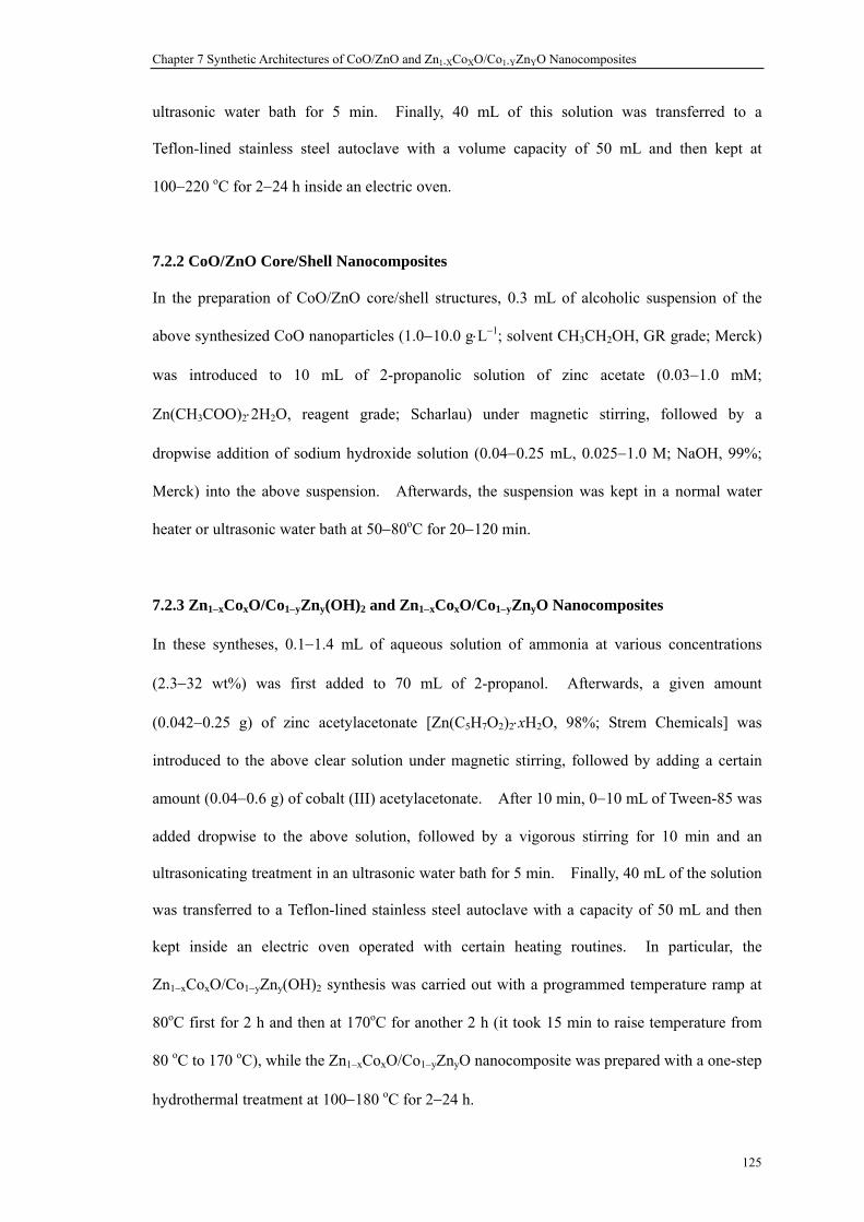
Chapter 7 Synthetic Architectures of CoO/ZnO and Zn1-XCoXO/Co1-YZnYO Nanocomposites
125
ultrasonic water bath for 5 min. Finally, 40 mL of this solution was transferred to a
Teflon-lined stainless steel autoclave with a volume capacity of 50 mL and then kept at
100−220 oC for 2−24 h inside an electric oven.
7.2.2 CoO/ZnO Core/Shell Nanocomposites
In the preparation of CoO/ZnO core/shell structures, 0.3 mL of alcoholic suspension of the
above synthesized CoO nanoparticles (1.0−10.0 g⋅L−1; solvent CH3CH2OH, GR grade; Merck)
was introduced to 10 mL of 2-propanolic solution of zinc acetate (0.03−1.0 mM;
Zn(CH3COO)2⋅2H2O, reagent grade; Scharlau) under magnetic stirring, followed by a
dropwise addition of sodium hydroxide solution (0.04−0.25 mL, 0.025−1.0 M; NaOH, 99%;
Merck) into the above suspension. Afterwards, the suspension was kept in a normal water
heater or ultrasonic water bath at 50−80oC for 20−120 min.
7.2.3 Zn1−xCoxO/Co1−yZny(OH)2 and Zn1−xCoxO/Co1−yZnyO Nanocomposites
In these syntheses, 0.1−1.4 mL of aqueous solution of ammonia at various concentrations
(2.3−32 wt%) was first added to 70 mL of 2-propanol. Afterwards, a given amount
(0.042−0.25 g) of zinc acetylacetonate [Zn(C5H7O2)2⋅xH2O, 98%; Strem Chemicals] was
introduced to the above clear solution under magnetic stirring, followed by adding a certain
amount (0.04−0.6 g) of cobalt (III) acetylacetonate. After 10 min, 0−10 mL of Tween-85 was
added dropwise to the above solution, followed by a vigorous stirring for 10 min and an
ultrasonicating treatment in an ultrasonic water bath for 5 min. Finally, 40 mL of the solution
was transferred to a Teflon-lined stainless steel autoclave with a capacity of 50 mL and then
kept inside an electric oven operated with certain heating routines. In particular, the
Zn1−xCoxO/Co1−yZny(OH)2 synthesis was carried out with a programmed temperature ramp at
80oC first for 2 h and then at 170oC for another 2 h (it took 15 min to raise temperature from
80 oC to 170 oC), while the Zn1−xCoxO/Co1−yZnyO nanocomposite was prepared with a one-step
hydrothermal treatment at 100−180 oC for 2−24 h.

Chapter 7 Synthetic Architectures of CoO/ZnO and Zn1-XCoXO/Co1-YZnYO Nanocomposites
126
7.2.4 CO Oxidation Reaction
The above prepared oxide nanocomposites were tested for their catalytic activities using
oxidation of carbon monoxide as a model reaction. A continuous-flow glass reactor used in
this evaluation was inserted in a horizontal electric furnace, which allowed the catalytic
reaction to proceed at the temperature of 25−500 oC. A given amount of catalyst (15 mg) was
filled into the glass reactor (inner diameter = 5 mm), which was clamped by glass fiber to
prevent non-uniform distribution of catalyst along the radial direction. Prior to the catalytic
reactions of CO oxidation, the catalysts were treated firstly at 500 oC for 5 min, and a feed gas
stream (1 vol% carbon monoxide, 19 vol% air, and 80 vol% argon) was then charged into the
reactor at a flow-rate of 100 mL⋅min−1 at different temperatures (60−350 oC). At the same
time, an on-line Fourier transform infrared spectroscopic (FTIR) gas detector (Bio-Rad, Model
FTS-3500 and TGA/FTIR accessory) was employed to analyze the gas product effluent in the
reactor outlet.39
Sample Preparation Details
Figure 7-2a-c
0.6 g of cobalt acetylacetonate was added to 70 mL of 2-propanol solution (which was made of 70 mL of 2-propanol, 0.7 mL of 32 wt% ammonia aqueous solution, and 0.7 mL of DI water), followed by stirring for 10 min and 5-min sonication in an ultrasonic water bath. 40 mL of the above solution was transferred into a Teflon-lined stainless steel autoclave, and the hydrothermal synthesis was conducted at 140 oC for 6 h in an electric oven.
Figure 7-2d-f
0.6 g of cobalt acetylacetonate was added to 70 mL of 2-propanol solution (which was made of 70 mL of 2-propanol, 0.7 mL of 32 wt% ammonia aqueous solution, and 0 mL of DI water), followed by stirring for 10 min and 5-min sonication in an ultrasonic water bath. 40 mL of the above solution was transferred into a Teflon-lined autoclave, and the hydrothermal synthesis was conducted at 180 oC for 6 h in an electric oven.
Figure 7-2g-i
0.6 g of cobalt acetylacetonate was added to 70 mL of 2-propanol solution (which was made of 70 mL of 2-propanol, 0.7 mL of 32 wt% ammonia aqueous solution, and 0.7 mL of DI water), followed by stirring for 10 min. Afterwards, 10 mL of Tween-85 was added dropwise to the above solution under magnetic stirring, followed by 5 min sonication in an ultrasonic water bath. 40 mL of the above solution was transferred into a Teflon-lined autoclave, and the hydrothermal synthesis was conducted at 180 oC for 12 h in an electric oven.
Figure 7-2j
0.6 g of cobalt acetylacetonate was added to 70 mL of 2-propanol solution (which was made of 70 mL of 2-propanol, 0.7 mL of 32 wt% ammonia aqueous solution, and 0.7 mL of DI water), followed by stirring for 10 min and 5-min sonication in an ultrasonic water bath. 40 mL of the above solution was transferred into a Teflon-lined stainless steel autoclave, and the hydrothermal synthesis was conducted at 140 oC for 2-12 h (for the synthesis of β-Co(OH)2 and Co(OH)2/CoO) or 180 oC for 6 h (for the synthesis of pure CoO) in an electric oven.
Figure 7-3a-d
(a) 0.3 g of cobalt acetylacetonate was added to 70 mL of 2-propanol solution (which was made of 70 mL of 2-propanol, 0.7 mL of 32 wt% ammonia aqueous solution, and 0.7 mL of DI water), followed by stirring for 10 min. Afterwards, 10 mL of Tween-85 was added dropwise to the above solution under magnetic stirring, followed by 5 min sonication in an ultrasonic water bath. 40 mL of the above solution was transferred into a Teflon-lined

Chapter 7 Synthetic Architectures of CoO/ZnO and Zn1-XCoXO/Co1-YZnYO Nanocomposites
127
autoclave, and the hydrothermal synthesis was conducted at 180 oC for 4 h in an electric oven. (b) 0.6 g of cobalt acetylacetonate was added to 70 mL of 2-propanol solution (which was made of 70 mL of 2-propanol, 0.7 mL of 32 wt% ammonia aqueous solution, and 0.7 mL of DI water), followed by stirring for 10 min. Afterwards, 10 mL of Tween-85 was added dropwise to the above solution under magnetic stirring, followed by 5 min sonication in an ultrasonic water bath. 40 mL of the above solution was transferred into a Teflon-lined autoclave, and the hydrothermal synthesis was conducted at 180 oC for 4 h in an electric oven. (c) and (d) 0.6 g of cobalt acetylacetonate was added to 70 mL of 2-propanol solution (which was made of 70 mL of 2-propanol, 0.7 mL of 32 wt% ammonia aqueous solution, and 0.7 mL of DI water), followed by stirring for 10 min. Afterwards, 0 mL of Tween-85 was added dropwise to the above solution under magnetic stirring, followed by 5 min sonication in an ultrasonic water bath. 40 mL of the above solution was transferred into a Teflon-lined autoclave, and the hydrothermal synthesis was conducted at 180 oC for 6 h in an electric oven.
Figure 7-4a-f The same as Figure 7-2g-i Figure 7-5a-c The same as Figure 7-2g-i
Figure 7-6a-c
0.3 mL of ethanolic suspension of cobalt oxide nanoparticles (1.0 g/L) was mixed with 10 mL of Zn(Ac)2 solution in 2-propanol ([Zn2+] = 0.03 mM), followed by dropwise introducing 0.075 mL of NaOH solution ([NaOH] = 0.010 M) into above solution. Then the mixture was stirred in a water bath at 70 oC for 60 min.
Figure 7-6d-f
0.3 mL of ethanolic suspension of cobalt oxide nanoparticles (10.0 g/L) was mixed with 10 mL of Zn(Ac)2 solution in 2-propanol ([Zn2+] = 0.04 mM), followed by dropwise introducing 0.04 mL of NaOH solution ([NaOH] = 0.025 M) into above solution. Then the mixture was treated in a ultrasonication water bath at 70 oC for 60 min.
Figure 7-6g-i
0.3 mL of ethanolic suspension of cobalt oxide nanoparticles (10.0 g/L) was mixed with 10 mL of Zn(Ac)2 solution in 2-propanol ([Zn2+] = 0.05 mM), followed by dropwise introducing 0.05 mL of NaOH solution ([NaOH] = 0.025 M) into above solution. Then the mixture was treated in a ultrasonication water bath at 70 oC for 60 min.
Figure 7-6j-l
0.3 mL of ethanolic suspension of cobalt oxide nanoparticles (10.0 g/L) was mixed with 10 mL of Zn(Ac)2 solution in 2-propanol ([Zn2+] = 0.10 mM), followed by dropwise introducing 0.10 mL of NaOH solution ([NaOH] = 0.025 M) into above solution. Then the mixture was treated in a ultrasonication water bath at 70 oC for 60 min.
Figure 7-6m-o
0.3 mL of ethanolic suspension of cobalt oxide nanoparticles (10.0 g/L) was mixed with 10 mL of Zn(Ac)2 solution in 2-propanol ([Zn2+] = 0.20 mM), followed by dropwise introducing 0.10 mL of NaOH solution ([NaOH] = 0.050 M) into above solution. Then the mixture was treated in a ultrasonication water bath at 70 oC for 60 min.
Figure 7-7a,b The same as Figure 6a-c
Figure 7-7c
0.3 mL of ethanolic suspension of cobalt oxide nanoparticles (10.0 g/L) was mixed with 10 mL of Zn(Ac)2 solution in 2-propanol. ([Zn2+] = 0.03 mM), followed by dropwise introducing 0.075 mL of NaOH solution ([NaOH] = 0.010 M) into above solution. Then the mixture was treated in a ultrasonication water bath at 70 oC for 60 min.
Figure 7-8
(a) 0.3 mL of ethanolic suspension of cobalt oxide nanoparticles (1.0 g/L) was mixed with 10 mL of Zn(Ac)2 solution in 2-propanol ([Zn2+] = 0.20 mM), followed by dropwise introducing 0.10 mL of NaOH solution ([NaOH] = 0.050 M) into above solution. Then the mixture was treated in a water bath at 55 oC for 60 min. (b) 0.3 mL of ethanolic suspension of cobalt oxide nanoparticles (10.0 g/L) was mixed with 10 mL of Zn(Ac)2 solution in 2-propanol ([Zn2+] = 0.20 mM), followed by dropwise introducing 0.10 mL of NaOH solution ([NaOH] = 0.050 M) into above solution. Then the mixture was treated in an ultrasonication water bath at 70 oC for 60 min.
Figure 7-9a-c
0.021 g of zinc acetylacetonate and 10 mL of cobalt acetylacetonate solutions (0.02 g/mL in 2-propanol) were added to 60 mL of 2-propanol solution (which was made of 60 mL of 2-propanol, 0.7 mL of 32 wt% ammonia aqueous solution, and 0.7 mL of DI water), followed by stirring for 10 min. Afterwards, 10 mL of Tween-85 was added dropwise to the above solution under magnetic stirring, followed by 5 min sonication in an ultrasonic water bath. 40 mL of the above solution was transferred into a Teflon-lined autoclave, and the hydrothermal synthesis was conducted at 80 oC for 2 h and 170oC for 1 h in an electric oven.
Figure 7-9d-f
0.084 g of zinc acetylacetonate and 10 mL of cobalt acetylacetonate solutions (0.02 g/mL in 2-propanol) were added to 60 mL of 2-propanol solution (which was made of 60 mL of 2-propanol, 0.7 mL of 32 wt% ammonia aqueous solution, and 0.7 mL of DI water), followed by stirring for 10 min. Afterwards, 10 mL of Tween-85 was added dropwise to the above solution under magnetic stirring, followed by 5 min sonication in an ultrasonic water bath. 40 mL of the above solution was transferred into a Teflon-lined autoclave, and the hydrothermal synthesis was conducted at 160 oC for 4 h in an electric oven.

Chapter 7 Synthetic Architectures of CoO/ZnO and Zn1-XCoXO/Co1-YZnYO Nanocomposites
128
Figure 7-9g-i
0.2 g of cobalt acetylacetonate and 0.084 g of zinc acetylacetonate were added to 70 mL of 2-propanol solution (which was made of 70 mL of 2-propanol, 0.7 mL of 32 wt% ammonia aqueous solution, and 0.7 mL of DI water), followed by stirring for 10 min. Afterwards, 10 mL of Tween-85 was added dropwise to the above solution under magnetic stirring, followed by 5 min sonication in an ultrasonic water bath. 40 mL of the above solution was transferred into a Teflon-lined autoclave, and the hydrothermal synthesis was conducted at 180 oC for 4 h in an electric oven.
Figure 7-9j-l
0.2 g of cobalt acetylacetonate and 0.125 g of zinc acetylacetonate were added to 70 mL of 2-propanol solution (which was made of 70 mL of 2-propanol, 0.7 mL of 32 wt% ammonia aqueous solution, and 0.7 mL of DI water), followed by stirring for 10 min. Afterwards, 10 mL of Tween-85 was added dropwise to the above solution under magnetic stirring, followed by 5 min sonication in an ultrasonic water bath. 40 mL of the above solution was transferred into a Teflon-lined autoclave, and the hydrothermal synthesis was conducted at 180 oC for 2 h in an electric oven.
Figure 7-10a-e
0.084 g of zinc acetylacetonate and 10 mL of cobalt acetylacetonate solutions (0.02 g/mL in 2-propanol) were added to 60 mL of 2-propanol solution (which was made of 60 mL of 2-propanol, 0.7 mL of 32 wt% ammonia aqueous solution, and 0.7 mL of DI water), followed by stirring for 10 min. Afterwards, 10 mL of Tween-85 was added dropwise to the above solution under magnetic stirring, followed by 5 min sonication in an ultrasonic water bath. 40 mL of the above solution was transferred into a Teflon-lined autoclave, and the hydrothermal synthesis was conducted at 80 oC for 2 h and 170oC for 2 h in an electric oven.
Figure 7-11
Zn1-xCoxO/Co1-yZnyO: 0.084 g of zinc acetylacetonate and 10 mL of cobalt acetylacetonate solutions (0.02 g/mL in 2-propanol) were added to 60 mL of 2-propanol solution (which was made of 60 mL of 2-propanol, 0.7 mL of 32 wt% ammonia aqueous solution, and 0.3 mL of DI water), followed by stirring for 10 min. Afterwards, 5 mL of Tween-85 was added dropwise to the above solution under magnetic stirring, followed by 5 min sonication in an ultrasonic water bath. 40 mL of the above solution was transferred into a Teflon-lined autoclave, and the hydrothermal synthesis was conducted at 180 oC for 4 h in an electric oven. Zn1-xCoxO/Co1-yZny(OH)2: 0.084 g of zinc acetylacetonate and 10 mL of cobalt acetylacetonate solutions (0.02 g/mL in 2-propanol) were added to 60 mL of 2-propanol solution (which was made of 60 mL of 2-propanol, 0.7 mL of 32 wt% ammonia aqueous solution, and 0.7 mL of DI water), followed by stirring for 10 min. Afterwards, 10 mL of Tween-85 was added dropwise to the above solution under magnetic stirring, followed by 5 min sonication in an ultrasonic water bath. 40 mL of the above solution was transferred into a Teflon-lined autoclave, and the hydrothermal synthesis was conducted at 80 oC for 2 h and 170 oC for 2 h in an electric oven.
Figure 7-12
0.084 g of zinc acetylacetonate and 10 mL of cobalt acetylacetonate solutions (0.02 g/mL in 2-propanol) were added to 60 mL of 2-propanol solution (which was made of 60 mL of 2-propanol, 0.7 mL of 32 wt% ammonia aqueous solution, and 0.7 mL of DI water), followed by stirring for 10 min. Afterwards, 0-10 mL of Tween-85 was added dropwise to the above solution under magnetic stirring, followed by 5 min sonication in an ultrasonic water bath. 40 mL of the above solution was transferred into a Teflon-lined autoclave, and the hydrothermal synthesis was conducted at 80 oC for 2 h and 170 oC for 2 h in an electric oven.
Figure 7-13a-c
0.16 g of cobalt acetylacetonate and 0.084 g of zinc acetylacetonate were added to 70 mL of 2-propanol solution (which was made of 70 mL of 2-propanol, 0.7 mL of 32 wt% ammonia aqueous solution, and 0.7 mL of DI water), followed by stirring for 10 min. Afterwards, 5 mL of Tween-85 was added dropwise to the above solution under magnetic stirring, followed by 5 min sonication in an ultrasonic water bath. 40 mL of the above solution was transferred into a Teflon-lined autoclave, and the hydrothermal synthesis was conducted at 180 oC for 4 h in an electric oven.
Figure 7-13d-i
0.084 g of zinc acetylacetonate and 10 mL of cobalt acetylacetonate solutions (0.02 g/mL in 2-propanol) were added to 60 mL of 2-propanol solution (which was made of 60 mL of 2-propanol, 0.7 mL of 32 wt% ammonia aqueous solution, and 0.3 mL of DI water), followed by stirring for 10 min. Afterwards, 5 mL of Tween-85 was added dropwise to the above solution under magnetic stirring, followed by 5 min sonication in an ultrasonic water bath. 40 mL of the above solution was transferred into a Teflon-lined autoclave, and the hydrothermal synthesis was conducted at 180 oC for 4 h in an electric oven.
Figure 7-14
0.084 g of zinc acetylacetonate and 10 mL of cobalt acetylacetonate solutions (0.02 g/mL in 2-propanol) were added to 60 mL of 2-propanol solution (which was made of 60 mL of 2-propanol, 1.0 mL of 32 wt% ammonia aqueous solution, and 0 mL of DI water), followed by stirring for 10 min. Afterwards, 5 mL of Tween-85 was added dropwise to the above solution under magnetic stirring, followed by 5 min sonication in an ultrasonic water bath. 40 mL of the above solution was transferred into a Teflon-lined autoclave, and the hydrothermal synthesis was conducted at 170 oC for 2-4 h in an electric oven.

Chapter 7 Synthetic Architectures of CoO/ZnO and Zn1-XCoXO/Co1-YZnYO Nanocomposites
129
Figure 7-15
0.084 g of zinc acetylacetonate and 10 mL of cobalt acetylacetonate solutions (0.02 g/mL in 2-propanol) were added to 60 mL of 2-propanol solution (which was made of 60 mL of 2-propanol, 0.7 mL of 32 wt% ammonia aqueous solution, and 0.1-0.7 mL of DI water), followed by stirring for 10 min. Afterwards, 5 mL of Tween-85 was added dropwise to the above solution under magnetic stirring, followed by 5 min sonication in an ultrasonic water bath. 40 mL of the above solution was transferred into a Teflon-lined autoclave, and the hydrothermal synthesis was conducted at 180 oC for 4 h in an electric oven.
Figure 7-16a-d The same as Figure 7-13d-i Figure 7-17a-d The same as Figure 7-13d-i
Figure 7-17e
0.084 g of zinc acetylacetonate and 10 mL of cobalt acetylacetonate solutions (0.02 g/mL in 2-propanol) were added to 60 mL of 2-propanol solution (which was made of 60 mL of 2-propanol, 0.7 mL of 32 wt% ammonia aqueous solution, and 0.3 mL of DI water), followed by stirring for 10 min. Afterwards, 5 mL of Tween-85 was added dropwise to the above solution under magnetic stirring, followed by 5 min sonication in an ultrasonic water bath. 40 mL of the above solution was transferred into a Teflon-lined autoclave, and the hydrothermal synthesis was conducted at 180 oC for 6 h in an electric oven.
Figure 7-18a,b
15 mg of catalysts was filled into glass tubing, which was clamped by glass fiber to prevent non-uniform distribution of catalyst along radial direction. Before CO oxidation reaction began, the catalysts need a heat-treatment at 500 oC for 5 min. Afterwards, the reactant gas (1 vol% CO, 19 vol% air, and 80 vol% argon) was charged into reactor with the flow rate of 100 ml/mina at various reaction temperatures between 60 and 350 oC. The effluent gas was analyzed by an online infrared (IR) gas detector.
Table 7-1 Preparation details and for the samples reported.

Chapter 7 Synthetic Architectures of CoO/ZnO and Zn1-XCoXO/Co1-YZnYO Nanocomposites
130
7.3 Results and Discussion
Figure 7-1 depicts some key synthetic steps for two different types of metal-oxide
nanocomposites prepared in this work. Firstly, in Figure 7-2, we examine the formation
process of pure CoO nanoparticles according to route (a) of Figure 7-1 and Equations (1) to (2).
At low reaction temperatures (e.g., 140 oC), flowerlike solid precursor can be arrested (Figure
7-2a-c). These flowerlike spheres were formed from a self-assembly of ultra-thin sheets of
β-Co(OH)2 (in brucite structure; Figure 7-2j).40 Concerning the reduction of Co3+ [of
Co(C5H7O2)3] to Co2+ [of β-Co(OH)2], one should recognize certain reducing power of
alcohols (e.g., 2-propanol, Equation (1)) under this reaction condition.41,42 At 180 oC,
hydrothermal conversion of β-Co(OH)2 to CoO takes place (Equation (2)).
Co(C5H7O2)3 + (CH3)2CHOH → Co2+ (1)
Co2+ + 2 OH− → β-Co(OH)2 → CoO + H2O (2)
Interestingly, initial nanocrystallites of CoO take a pseudo-cubic shape and arrange themselves
into lines under our TEM measurement conditions (Figure 7-2d-f).43-46 The observed
morphology may reflect intrinsic crystallographic symmetry of CoO that belongs to cubic
crystal system (JCPDS card no. 71-1178). With a longer reaction time, the CoO nanocubes
are developed into larger spherical particles (Figure 7-2g-i). The CoO spheres are quite
uniform with an average diameter of about 100 nm (Figure 7-2i). Apart from the reaction
temperature and time, other synthetic parameters can also affect the growth of CoO
nanoparticles. For instance, the size of nanoparticles depends on the concentration of cobalt
acetylacetonate in the starting solution. The average size of CoO nanoparticles synthesized
with 3.75 g⋅L−1 of cobalt acetylacetonate in initial concentration was below 10 nm (Figure
7-3a). However, the size could be increased to around 100 nm when an initial concentration
of 7.50 g⋅L−1 was used (Figure 7-3b-d). This observation was expected, because the nutrient
supply of cobalt to the growth had been doubled in the latter case.

Chapter 7 Synthetic Architectures of CoO/ZnO and Zn1-XCoXO/Co1-YZnYO Nanocomposites
131
Figure 7-1 Schematic illustrations for formation processes of nanocomposites: (a) formation processes of CoO nanospheres and CoO/ZnO core/shell nanocomposites; and (b) formation processes of Zn1−xCoxO/Co1−yZny(OH)2 and Zn1−xCoxO/Co1−yZnyO nanocomposites. Note that the sizes in the above drawings are not proportional to actual product dimensions. For instance, actual sizes of CoO and Co1−yZnyO nanospheres are in the same dimensional order in their respective products.
(a)
(b)
Co(OH)2 nanoflowers CoO nanocrystallites
CoO nanospheres CoO/ZnO core/shell
Zn1−xCoxO nanocrystallites
Zn1−xCoxO nanospheres Zn1−xCoxO/Co1−yZny(OH)2
core/shell
Zn1−xCoxO/Co1−yZnyOnanocomposites

Chapter 7 Synthetic Architectures of CoO/ZnO and Zn1-XCoXO/Co1-YZnYO Nanocomposites
132
Figure 7-2 TEM images of reaction products at different process stages (also refer to route (a) of Figure 7-1): (a-c) flowerlike aggregates of β-Co(OH)2 solid precursor, (d-f) intermediate CoO nanoparticles in pseudo-cubic shape, and (g-i) nanospheres of CoO; (j) XRD pattern evolution of β-Co(OH)2 to CoO.
(a) (b) (c)
(d) (e) (f)
(g) (h) (i)
(j)

Chapter 7 Synthetic Architectures of CoO/ZnO and Zn1-XCoXO/Co1-YZnYO Nanocomposites
133
Figure 7-3 TEM images of synthesized CoO particles under different synthetic conditions.
The XRD pattern of as-obtained CoO nanospheres is shown in Figure 7-4a; all diffraction
peaks can be well indexed as the cubic CoO phase (space group: Fm3m; a rock-salt structure
with the lattice parameters ao = bo = co = 0.426 nm; JCPDS card no. 71-1178). Furthermore,
the TEM image displayed in Figure 7-4b reveals that these CoO spheres comprise numerous
smaller crystallites, while our SAED result indicates that the spheres are single-crystalline in
nature, since the electron diffraction pattern can be assigned thoroughly to the [−112]
diffraction zone spots (Figure 7-4c). This assignment for the reciprocal lattices is also
confirmed with a diffraction pattern simulation with the software of Materials Studio.47 Our
HRTEM data further reveal that the crystallites in the CoO spheres are about 3−4 nm (Figure
7-4d), leaving some inter-crystallite spaces. On the other hand, long range order of lattice
fringes (e.g., d111 = 0.25 nm) of CoO has been demonstrated, although crystal defects are also
observed around the crystallite boundaries (Figure 7-4e). In this regard, therefore, the
resultant CoO nanospheres can also be considered as mesocrystals.26 This type of crystallite
aggregation has been now widely recognized as an “oriented attachment” mechanism.30,48-50
(a) (b
(c) (d

Chapter 7 Synthetic Architectures of CoO/ZnO and Zn1-XCoXO/Co1-YZnYO Nanocomposites
134
Figure 7-4 Materials characterization of CoO nanospheres: (a) XRD pattern, (b,c) an aggregative CoO nanosphere and its SAED pattern (i.e., [−112] zone diffraction spots), (d,e) HRTEM images of a CoO nanosphere (d111 = 0.25 nm). Color inset illustrates the crystal structure of the (−112) plane (Co atoms are in blue and light-blue, and O atoms in red and pink), and (f) computer simulation of diffraction pattern (-112) zone spots.
Surface sensitive technique XPS was also employed in this work to elucidate the formation of
pure CoO nanospheres. As shown in Figure 7-5a, the predominant C 1s peak at 284.6 eV
belongs to surface-adsorbed hydrocarbons.48,51 The small peaks at 286.2 and 288.4 eV can be
attributed to oxidative forms of the surface hydrocarbons (e.g., hydroxyl carbon C−OH and
ether C−O−C) and carboxylate moiety on the final product.48,51 Furthermore, the components
revealed in O 1s spectra also demonstrate the similar results (Figure 7-5b). The peaks at
529.8 and 530.2 eV can be assigned to lattice oxygen species in surface Co3O4 and CoO
respectively; the spinel oxide of cobalt (Co3O4) is normally present on the surface of CoO for
30 40 50 60 70 80
222311
220
200
111In
tens
ity (a
.u.)
2 Theta (Degree)
(a)
(b)
-1-31 -2-20 -3-1-1
1-11 -11-1
311
220
13-1
(c)
(−112) plane of CoO
d111(d) (e)d111
d11d111
d11
[−112]
(f)

Chapter 7 Synthetic Architectures of CoO/ZnO and Zn1-XCoXO/Co1-YZnYO Nanocomposites
135
those samples handled in laboratory atmosphere.48,52-54 The peaks at 531.4, 532.2, and 533.4
eV can be ascribed to oxygen species in Co−OH, carboxylate ions, and H2O molecules,
respectively.48,54 Accordingly, Co 2p3/2 spectrum displayed in Figure 7-5c show two major
peaks at 779.8 and 780.0 eV, which can be assigned to Co3O4 and CoO, and their satellite
shake-ups are located at 782.5 and 786.2 eV respectively.48,54 It should be mentioned that the
peak at 786.2 eV is actually higher than that at 782.5 eV, because it has been well known that
divalent cobalt (CoO) normally exhibits a stronger satellite shake-up structure.48,54 Similar
assignments can also be performed for the corresponding peaks of the Co 2p1/2 branch located
at higher binding energies.48,54
Figure 7-5 X-ray photoelectron spectra measured from the as-prepared CoO nanospheres: (a) O 1s, (b) O 1s, and (c) Co 2p.
In addition to the synthesis of CoO phase, ZnO phase can also be introduced to the surface of
CoO nanospheres, giving rise to a CoO/ZnO core/shell structure (i.e., route (a), Figure 7-1).
In this work, we adopted an earlier solution approach that can produce ZnO nanoparticles
using simple precursor chemicals of zinc acetate and sodium hydroxide in water−2-proponol
reaction medium (see Experimental Section, and Equation (3)).34,35
Zn(CH3COO)2 + 2 OH− → Zn(OH)2 → ZnO + H2O (3)
(b) O 1s (a) C 1s
290 288 286 284 282
288.4 286.2
284.6
535 534 533 532 531 530 529 528
533.4
532.2531.4
530.2
529.8
810 805 800 795 790 785 780 775
802.5
798.7
796
795.4
786.2
782.5
780
779.8
(c) Co 2p
Binding Energy (eV)

Chapter 7 Synthetic Architectures of CoO/ZnO and Zn1-XCoXO/Co1-YZnYO Nanocomposites
136
As reported in Figure 7-6a-c, the CoO nanospheres cores are covered with a thin layer of ZnO
nanoparticles while their pristine shape is unaltered. It is further found that when the
concentration of zinc precursor is increased and less sodium hydroxide is used in synthesis,
ZnO nanoparticles may also form as a separate secondary phase in addition to the formation of
binary CoO/ZnO core/shell structures. Figure 7-6d-o shows this process as a function of zinc
precursor concentration under identical reaction conditions. The resultant CoO/ZnO core/shell
composites shown in Figure 7-6a-c have also been investigated with HRTEM and XRD
methods, as reported in Figure 7-7. In particular, d0002 lattice fringes of ZnO can be easily
observed in the shell structure of this composite, but not all ⟨0002⟩ directions are parallel,
which indicates that, unlike its mesocrystalline CoO core, the ZnO shell is comprised of
numerous randomly attached ZnO nanoparticles, as illustrated in Figure 7-7b. Nevertheless,
the lattices fringes of both CoO and ZnO match literature data perfectly, indicating successful
formation of the core/shell structure. Similar to the HRTEM result, furthermore, the XRD
investigation of Figure 7-7c also confirms the co-presence of both CoO and ZnO phases in this
composite sample. The lattice parameters determined for ZnO nanoparticles are ao = 0.325 nm
and co = 0.521 nm respectively, which are identical to those of pure wurtzite phase zinc oxide
(space group P63mc, ao = 0.325 nm, co = 0.521 nm, JCPDS card no. 89-0511).55-57
Apart from the control of precursor contents, two important process parameters (temperature
and sonication) were also identified. It should be mentioned that the above ZnO
nanoparticles are formed through hydrolysis/precipitation of zinc acetate and thermal
decomposition of Zn(OH)2 at 70 oC. At lower process temperatures (e.g., 50 oC), thin flake-like
Zn(OH)2 phase is still present, and nanocrystalline product ZnO cannot be formed (Figure
7-8a). Furthermore, it should also be pointed out that the above heating process conducted
inside an ultrasonic water bath can give a fuller coating of ZnO nanocrystallites, because the
CoO (core) nanospheres can be dispersed more homogeneously in the solution prior to the
introduction of ZnO phase.

Chapter 7 Synthetic Architectures of CoO/ZnO and Zn1-XCoXO/Co1-YZnYO Nanocomposites
137
Figure 7-6 TEM images of CoO/ZnO nanocomposites: (a-c) CoO/ZnO core/shell structures, (d-o) CoO/ZnO core/shell structures synthesized with increasing concentrations of zinc acetate.
(d) (e) (f)
(g) (h) (i)
(j) (k) (l)
(m) (n) (o)
(a) (b) (c)

Chapter 7 Synthetic Architectures of CoO/ZnO and Zn1-XCoXO/Co1-YZnYO Nanocomposites
138
Figure 7-7 Characterization of CoO/ZnO core/shell nanocomposites: (a) HRTEM image of interfacial region between core (CoO nanosphere) and shell (ZnO overlayer), (b) HRTEM image focused on ZnO overlayer [refer to (a); d0002 = 0.26 nm], and (c) XRD pattern of this sample.
Figure 7-8 TEM images of formation of nanocomposites under various reaction temperatures: (a) 55 oC (formation of CoO/Zn(OH)2), and (b) 70 oC (formation of CoO/ZnO).
(a)
30 40 50 60 70 80
* ZnOo CoO
(222)(311)(220)
(200)
(111)o
o o
o
o
(201)(112)
(103)(110)
(102)
(101)
(002)
(100)
*
*
** *
**
*
2 Theta (Degree)
(c)
Inte
nsity
(a.u
.)
(b)
d0002
d0002
d0002
CoO
ZnO
ZnO
Zn(OH)2
ZnO
(a)
(b)

Chapter 7 Synthetic Architectures of CoO/ZnO and Zn1-XCoXO/Co1-YZnYO Nanocomposites
139
In the above preparation of CoO/ZnO nanocomposites, the ZnO shell was introduced onto the
pre-made CoO core in a new reaction environment (i.e., under “two pots” conditions, route (a),
Figure 7-1). In the present work, we also prepared Zn,Co-containing binary oxide/hydroxide
nanocomposites under “one pot” conditions, that is, both zinc and cobalt precursors were
charged into the same reactor prior to reactions took place. Understandably, due to different
chemical natures of cations [Zn2+ and Co2+ (from Equation (1)] the reaction products may not
form simultaneously. Because zinc and cobalt are both divalent cations in this materials
system, a certain degree of inter-doping is expected, as indicated in route (b) of Figure 7-1 and
Equations (4) and (5).
(1−x) Zn(C5H7O2)2 + x Co2+ + 2 OH− → Zn1−xCox(OH)2 → Zn1−xCoxO + H2O (4)
(1−y) Co2+ + y Zn(C5H7O2)2 + 2 OH− → Co1−yZny(OH)2 → Co1−yZnyO + H2O (5)
With the co-presence of both zinc and cobalt acetylacetonates, indeed, doped metal oxides and
hydroxides can be prepared under hydrothermal conditions (see Experimental Section).
Figure 7-9 displays some representative product crystal morphologies. When the concentration
of zinc salt is low, small Zn1−xCoxO particles [dark spots; see Equation (4)] are formed and
connected to particulate Co1−yZny(OH)2 aggregates (lighter image contrasts), as shown in
Figure 7-9a-c. When concentrations between zinc and cobalt become comparable, Zn1−xCoxO
phase is made as cores while the Co1−yZny(OH)2 phase as shells (Figure 7-9-d-i) in the
composite system. In good agreement with this general observation, furthermore, thin
Co1−yZny(OH)2 shells or even bare Zn1−xCoxO cores have been found when the concentration
of zinc salt becomes exceedingly higher. In many of our samples, interestingly, multi-shelled
Zn1−xCoxO cores with hollow interior spaces have been observed (Figure 7-9j-l; also see Figure
7-13b later), suggesting that Ostwald ripening mechanism was an underlying process operative
in these syntheses.58-60

Chapter 7 Synthetic Architectures of CoO/ZnO and Zn1-XCoXO/Co1-YZnYO Nanocomposites
140
Figure 7-9 TEM images of Zn1−xCoxO/Co1−yZny(OH)2 nanocomposites (also refer to route (b) of Figure 7-1): (a-c) formation of Zn1−xCoxO (indicated by white arrows) imbedded in Co1−yZny(OH)2 particles, (d-i) formation of solid and hollow Zn1−xCoxO/Co1−yZny(OH)2 core/shell structures, and (j-l) formation of multi-shelled Zn1−xCoxO core in Zn1−xCoxO/Co1−yZny(OH)2 core/shell nanocomposites.
Based on our XRD investigation reported in Figure 7-10, it is known that the Zn1−xCoxO cores
are still in a wurtzite structure, and the lattice parameters for the wurtzite phase were measured
at ao = 0.324 nm and co = 0.518 nm (versus literature data ao = 0.325 nm and co = 0.521 nm for
pure ZnO; JCPDS card no. 89-0511), respectively, indicating some shrinkage of lattice
structure due to zinc substitution with smaller cobalt ions [Zn1−xCoxO, where x = 0.20−0.27
based on EDX analysis, Table 7-2; NB: ionic radii r(Co2+) = 0.73 Å and r(Zn2+) = 0.74 Å].
(a) (b) (c)
(d) (e) (f)
(g) (h) (i)
(j) (k) (l)

Chapter 7 Synthetic Architectures of CoO/ZnO and Zn1-XCoXO/Co1-YZnYO Nanocomposites
141
Nevertheless, the shell phase Co1−yZny(OH)2 (y = 0.02−0.04 based on our EDX analysis, Table
7-2) does not show any diffraction pattern, suggesting that it is in an amorphous state,40,48
although two types of TEM image contrasts for the core/shell structures are clearly
differentiable in Figure 7-9. This noncrystalline solid state may be attributed to a defective
structure resulted from the co-precipitation of the bi-metal hydroxides, randomly mixed with
the surfactant chemical Tween-85 and/or its derivatives produced in these syntheses (see our
FTIR results, Figure 7-11).48
Figure 7-10 XPS spectra (a-d) and XRD pattern (e) of Zn1−xCoxO/Co1−yZny(OH)2 nanocomposites with a hollow Zn1−xCoxO core (illustrated in (f)); also refer to route (b) of Figure 7-1.
290 288 286 284 282
288.4
286.3
284.6
534 533 532 531 530 529 528
533.4
532.2
531.1
530.1 529.9
805 800 795 790 785 780 775
802.6 798.5796.7
795.7
786.5782.6
780.6
780.2
1045 1040 1035 1030 1025 1020
1021.2
1044.2
30 40 50 60 70 80
(201)(112)(103)
(110)(102)
(101)
(002)
(100)
Inte
nsity
(a.u
.)
2 Theta (Degree)
Binding Energy
(a) C 1s
(b) O 1s
(c) Co 2p
(d) Zn 2p
(e
(f)

Chapter 7 Synthetic Architectures of CoO/ZnO and Zn1-XCoXO/Co1-YZnYO Nanocomposites
142
sample name core phase X shell phase y
CoO/ZnO CoO (1.0) ZnO (1.0)
Zn1−xCoxO/Co1−yZny(OH)2 Zn1−xCoxO 0.20−0.27 Co1−yZny(OH)2 0.02−0.04
Zn1−xCoxO/Co1−yZnyO Zn1−xCoxO 0.10−0.17 Co1−yZnyO 0.33−0.37
Table 7-2 Summaries of nanocomposites synthesized in this work and their metal ions relative populations.
Figure 7-11 FTIR spectra of Zn1−xCoxO/Co1−yZny(OH)2 vs Zn1−xCoxO/Co1−yZnyO. The peaks at 1560-1565 cm-1 and 1403-1405 cm-1 are assigned to stretching vibrations of carboxylate group, –COO− [νas(OCO) and νs(OCO)]. The peaks at 2926-2928 and 2852-2854 cm-1 are assigned to asymmetric and symmetric C–H stretching modes [νas(CH2) and νs(CH2)], respectively. All these observations collectively reveal that an organic species was generated from the hydrophobic head group of Tween-85, i.e., alkylated oleate group CH3(CH2)7CHCHCH2CR2(CH2)5COO−, where R = CH2CHCHCH2 (CH2)6CH3; the carboxylate anion binds randomly with metal cations in the mixed metal hydroxide Co1−yZny(OH)2 because of no XRD diffraction patterns. The peaks at around 470 cm-1 are assigned to vibrational absorptions of metal–oxygen (M–O, M = Co and Zn) bonds.
Zn1−xCoxO/Co1−yZny(OH)2
Zn1−xCoxO/Co1−yZnyO

Chapter 7 Synthetic Architectures of CoO/ZnO and Zn1-XCoXO/Co1-YZnYO Nanocomposites
143
Without using Tween-85 in synthesis, however, crystalline Co1−yZny(OH)2 “petals” can be
formed around the Zn1−xCoxO cores (Figure 7-12). It has been further evidenced that Tween-85
is indispensible in order to create the Zn1−xCoxO/Co1−yZny(OH)2 core/shell structures in Figure
7-9. As indicated in Equations (1) and (5), the reduction of Co3+ [Co(C5H7O2)3] to Co2+ leads
to formation of divalent Co1−yZny(OH)2 and thus to Co1−yZnyO. On the basis of Figure 7-9, it
is also found that this reduction likely causes a delay in formation of Co1−yZny(OH)2 (and thus
the Co1−yZnyO), because this solid precursor is formed as a shell structure after the formation
of Zn1−xCoxO cores (Figure 7-9).
Figure 7-12 TEM images of Zn1−xCoxO/Co1−yZny(OH)2 nanocomposites with various surfactant (Tween-85) concentrations: (a) 0 mL, (b) 5 mL, and (c and d) 10 mL.
Compared to those assigned in Figure 7-5, the C 1s and O 1s peaks in Figure 7-10a,b show
significant changes due to formation of the mixed metal hydroxides in the shell structure. In
particular, the C 1s peak at 286.3 eV (e.g., hydroxyl carbon C−OH and ether C−O−C) becomes
larger, indicating more oxidative species of Tween-85 and/or its derivatives adsorbed on this
sample.48,51,57 On the other hand, the tiny component corresponding to carboxylate groups
(a) (b
(c) (d

Chapter 7 Synthetic Architectures of CoO/ZnO and Zn1-XCoXO/Co1-YZnYO Nanocomposites
144
(288.4 eV) still remains negligible,48 which rules out the possibility of intercalation of this
anionic species in this binary hydroxide compound (also see FTIR result, Figure 7-11).43 In
this agreement, a sharp increase in the O 1s peak at 531.1 eV (assigned to M−OH, where M =
Co2+ and Zn2+) indicates the predominant presence of the surface hydroxide
Co1−yZny(OH)2,48,51,61 and the O 1s peaks at 529.9, 530.1, 532.2, and 533.4 eV can be assigned
similarly to those in Figure 7-5b.48,52-54 In accordance to the large M−OH peak detected in the
O 1s spectrum, the large peak at 780.6 eV in the Co 2p3/2 spectrum of Figure 7-10c is ascribed
to Co2+−OH,48,51,54,61 while the smaller peak at 780.2 eV to a Zn2+-doped CoO surface phases,61
noting that the modification of zinc in the Co1−yZny(OH)2 shells is relatively small (y =
0.02−0.04, Table 7-2). Due to an abundant amount of divalent cobalt species (Co2+−OH and
Zn2+-doped CoO) on the shell surface, the satellite shake-up peaks at 786.5 and 782.6 eV are
rather strong.40,48,51,54,62-64 In a similar way, the Co 2p1/2 branch located at higher binding
energies can also be assigned to the corresponding species in the Co 2p3/2 branch. As expected,
the dopant element Zn is also detected (the doublet peaks of Zn 2p for divalent Zn2+,61 Figure
7-10d) although its content is low in the mixed hydroxide shell structure [Co1−yZny(OH)2].
Apart from the above synthetic parameters, other control factors for the growth have also been
examined in our work. For example, we found that the amounts of ammonia solution and
deionized water used in synthesis are very important for the morphological control. For
example, more water content in synthesis will increase the size of Zn1−xCoxO cores (see the
discussion for Figure 7-15 later). On the other hand, a lower concentration of ammonia
during the synthesis will give a poorer shell-morphology, because of insufficient alkaline
content for the hydrolysis of Tween-85 and the formation of the mixed metal hydroxide. As
an important process parameter, the heating routine also shows great influence on composite
products. In order to obtain this type of metal oxide and metal hydroxide composites, a
two-stage heating (80 oC for 2 h and 170 oC for 2 h, see Experimental Section) was developed.
This step is necessary because it ensures a more even temperature distribution in autoclaves
and thus a better control over the reaction products.

Chapter 7 Synthetic Architectures of CoO/ZnO and Zn1-XCoXO/Co1-YZnYO Nanocomposites
145
With higher reaction temperatures and longer reaction times, the Co1−yZny(OH)2 phase in the
above Zn1−xCoxO/Co1−yZny(OH)2 core/shell structures can be gradually converted to Co1−yZnyO,
resulting in a new type of binary metal oxide nanocomposites of Zn1−xCoxO/Co1−yZnyO
[Equation (5)]. Similar to pure CoO oxide demonstrated in Figure 7-2, interestingly, the
resultant Co1−yZnyO phase also adopts a spherical shape. Figure 7-13 shows crystal
morphologies of Zn1−xCoxO/Co1−yZnyO synthesized with our “one-pot” approach, noting that
the Zn1−xCoxO was turned exclusively to hollow cores. A time dependent evolution of oxide
shell formation (i.e., Co1−yZnyO from Co1−yZny(OH)2) has also been demonstrated in Figure
7-14.
Figure 7-13 TEM images of Zn1−xCoxO/Co1−yZnyO nanocomposites (also refer to route (b) of Figure 7-1): (a and b) panoramic views at different magnifications (i.e., Zn1−xCoxO/Co1−yZnyO core/shell structures, together with individual Co1−xZnxO nanospheres, and (c-i) detailed views of Zn1−xCoxO/Co1−yZnyO core/shell structures at different magnifications.
(a) (b) (c)
(e) (f)(d)
(h) (i)(g)

Chapter 7 Synthetic Architectures of CoO/ZnO and Zn1-XCoXO/Co1-YZnYO Nanocomposites
146
Figure 7-14 TEM images of different product morphologies after different reaction times: (a) 2 h, (b) 3 h, and (c and d) 4 h.
Consistent with the findings of their precursors Zn1−xCoxO/Co1−yZny(OH)2, the final complex
nanocomposites of Zn1−xCoxO/Co1−yZnyO also depend on a balance between zinc and cobalt
acetylacetonates set in the starting solutions. Low concentration of cobalt salt could result in
small Co1−yZnyO nanospheres adhering to their Zn1−xCoxO cores. On the other hand,
increasing cobalt concentration in synthesis would allow the Co1−yZnyO nanospheres to grow
into larger ones as well as to be formed as a separate phase (Figure 7-13a,b). As for zinc salt
used in this work, the higher the initial concentration, the higher the metal oxide ratio of
Zn1−xCoxO to Co1−yZnyO. Furthermore, our experimental results reveal that the amount of
water used in the synthesis plays an important role in the controlling the size of Co1−yZnyO
nanospheres. Keeping other synthetic parameters unchanged, a gradual variation of the
diameter in the range from 50 to 200 nm can be achieved by adding more water into the
syntheses (Figure 7-15). It is believed that the content of water is essential for hydrolysis of
both metal salts. On the other hand, the water may also weaken the binding of alkylated oleic
anionic surfactants attached to the nanocrystallites of oxides, resulting in an easy “oriented
(c) (d
(a) (b

Chapter 7 Synthetic Architectures of CoO/ZnO and Zn1-XCoXO/Co1-YZnYO Nanocomposites
147
attachment” among the crystallites.30,48-50,57
Figure 7-15 TEM images of Zn1−xCoxO/Co1−yZnyO nanocomposite with various water volumes in the reactions: (a, b) 0.43 mL, (c, d) 0.53 mL, and (e, f) 0.75 mL. Total solution volume was kept at 40 mL for all these syntheses.
The interfacial structure between Zn1−xCoxO core and its surface Co1−yZnyO nanosphere is
further examined in Figure 7-10a-b with HRTEM method. Apparently, the core of this
composite system is polycrystalline, because different ⟨0001⟩ orientations can be observed in
the same core (Figure 7-16c). However, the surface Co1−yZnyO seems to be single-crystalline,
and only one ⟨100⟩ direction can be seen across the same piece of nanosphere (Figure 7-16d).
(c)
(a) (b)
(d)
(e) (f)

Chapter 7 Synthetic Architectures of CoO/ZnO and Zn1-XCoXO/Co1-YZnYO Nanocomposites
148
Interestingly, the diameter of Co1−yZnyO nanospheres displayed in Figure 7-13 is in about the
same order as that of CoO nanospheres in Figure 7-2g-i, and both CoO and Co1−yZnyO
nanospheres are mesocrystalline. As expected, both the cores and shells were determined to
be solid solutions of mixed metal-oxides on the basis of our EDX analysis (Zn1−xCoxO, x =
0.10−0.17; and Co1−yZnyO, y = 0.33−0.37; Table 7-2). The zinc content (y value) in the
Co1−yZnyO nanospheres is significantly increased, compared to that of their solid precursor
Co1−yZny(OH)2. This content change is accompanied with a hollowing process for the
Zn1−xCoxO cores (Figure 7-13) during the formation of Co1−yZnyO phase [Equation (5)].
Figure 7-16 HRTEM images of Zn1−xCoxO/Co1−yZnyO nanocomposites (also refer to route (b) of Figure 7-1): (a) an overall view on interfacial region between Zn1−xCoxO core and its supported Co1−yZnyO nanospheres; (b) a detailed view on the framed area in (a); and (c and d) detailed views on two framed areas indicated in (b). Zn1−xCoxO phase: d0002 = 0.26 nm and Co1−yZnyO phase: d200 = 0.21 nm.
(a) (b)
(c) (d)
d0002
d0002
d200
Zn1−xCoxO Co1−yZnyO
Zn1−xCoxO
Co1−yZnyO
Zn1−xCoxO
Co1−yZnyO

Chapter 7 Synthetic Architectures of CoO/ZnO and Zn1-XCoXO/Co1-YZnYO Nanocomposites
149
In Figure 7-17a,b, the O 1s spectrum still shows a large hydroxyl peak at 531.3 eV while the
peaks at 530.3, 530.0 and 529.8 eV can be assigned to the lattice oxygen in Co1−yZnyO, CoO
and Co3O4 respectively,48,52-54 noting that the C 1s spectrum is essentially identical to that of
pure CoO (Figure 7-5a). Similar to those assigned in Figure 7-8c, in Figure 7-11c, the large
peak of the Co 2p3/2 peak at 780.4 eV is attributable to the surface species of Co2+−OH, and the
peaks at 780.3 and 779.9 eV are attributed to surface Zn2+-doped CoO (i.e., Co1−yZnyO) and
Co3O4 phases, respectively.48,51,54,61 Also, the peaks at 786.3 and 782.5 eV are assigned
largely to the satellite shake-up structures of divalent cobalt ions.62-64 Similarly, the
assignment for Co 2p1/2 branch located at higher BEs can also be done in accordance to their
Co 2p3/2 branch.48,51,54,61 The Zn 2p spectrum in Figure 7-17d shows a slight shift in BEs
(+0.2 eV) compared to that in Figure 7-10d, which indicates that there is a good mixing
between the Co2+ and Zn2+ in the Co1−yZnyO surface phase, resulted from formation of
Co2+−O−Zn2+ through which electronic charge can be transferred from Zn to Co,64 noting that
Co has a higher electronegativity compared to Zn (NB: Co = 1.88 versus Zn = 1.65). The
XRD patterns shown in Figure 7-17e can be assigned perfectly to a superimposition of
wurtzite Zn1−xCoxO and rock-salt Co1−yZnyO. The lattice constants for the former crystal
system are ao = 0.324 nm and co = 0.518 nm, and that for the latter is ao = 0.425 nm,
respectively. Consistent with our EDX finding, the Co2+-doped ZnO core (i.e., Zn1−xCoxO)
still maintains its wurtzite phase, noting that it has been reported that the wurtzite phase can be
maintained if x < 20 atomic %.36,65 Since zinc and cobalt have similar ionic radii, the
departures of lattice constants from those in the un-doped ZnO and CoO in both crystal phases
are almost negligible, although we note that the lattice constants in both mixed oxide phases
are slightly contracted.37

Chapter 7 Synthetic Architectures of CoO/ZnO and Zn1-XCoXO/Co1-YZnYO Nanocomposites
150
Figure 7-17 XPS spectra (a-d) and XRD pattern (e) of Zn1−xCoxO/Co1−yZnyO core/shell structures, together with individual Co1−yZnyO nanospheres (illustrated in (f)); also refer to route (b) of Figure 7-1.
290 289 288 287 286 285 284 283 282
288.4286.2
284.6
535 534 533 532 531 530 529
530.0533.5
532.2
531.3
530.3
529.8
810 805 800 795 790 785 780
802.6
798.6
796.6
795.5 795.1
786.3
782.5
780.4
780.3779.9
1045 1040 1035 1030 1025 1020
1044.4
1021.4
30 40 50 60 70 80
CoOZnO
o*
(222)o
(311)
(220)
(200)
(111)
o
o
o
o
(102)
**
*
*
* **
(112)(103)(110)
(101)
(002)
(100)
Inte
nsity
(a.u
.)
2 Theta (Degree)
(a) C 1s
(b) O 1s
(c) Co 2p
(d) Zn 2p
(e)
Binding Energy (eV )
(f)Zn1−xCoxO Co1−yZnyO

Chapter 7 Synthetic Architectures of CoO/ZnO and Zn1-XCoXO/Co1-YZnYO Nanocomposites
151
As a final note of this work, we have also carried out trial oxidation reactions of carbon
monoxide using our nanocomposite samples. It has been known that cobalt oxides are able to
catalyze oxidation reaction of carbon monoxide at low reaction temperature owing to their
multiple oxidation states and surface Lewis and Brønsted sites etc.66-68 In Figure 7-18, under
identical reaction conditions, the magnitude of vibrational IR absorptions of CO2 over 2300 to
2400 cm−1 indicates the easiness of production of CO2 from CO oxidation reactions. It can be
seen that both catalytic materials start to show their catalytic activities at a temperature as low
as 60oC, which increase significantly at 120−140oC. Although the two tested materials give
very similar catalytic performances, their metal constituents are vastly different. Our EDX
analysis shows that overall metal ion ratio in the Zn1−xCoxO/Co1−yZnyO composite system is
Co2+/Zn2+ = 56.7/43.3. Because the atomic weight of zinc is higher than that of cobalt, the
total cobalt ions in the Zn1−xCoxO/ Co1−yZnyO nanocomposite are about half of those in the
CoO nanospheres due to the same weight (15 mg) of catalysts was used in these two
evaluation experiments. Therefore, the cobalt ions in our complex Zn1−xCoxO/Co1−yZnyO
nanocomposite are significantly more active, compared with their phase-pure counterpart, CoO
nanospheres. It has been known that the presence of hydroxyl groups on surface of metal
oxides could be beneficial for CO adsorption and thus its oxidation to CO2.66 We note that
the population of hydroxyl groups on the Zn1−xCoxO/Co1−yZnyO (Figure 7-10b) is indeed
higher than that on pure CoO nanospheres (Figure 7-5b), which may explain the observation of
its better catalytic activity, apart from other possible synergetic contributions from the zinc
dopant in this composite catalyst.

Chapter 7 Synthetic Architectures of CoO/ZnO and Zn1-XCoXO/Co1-YZnYO Nanocomposites
152
Figure 7-18 FTIR spectra of reaction products of CO oxidation using two different cobalt containing catalytic materials at various reaction temperatures: (a) heat-treated CoO nanospheres, and (b) heat-treated Zn1−xCoxO/Co1−yZnyO core/shell structures, together with individual Co1−yZnyO nanospheres.
7.4 Conclusions
In summary, we have investigated synthetic architectures of two inverse types of cobalt and
zinc oxide nanocomposites, CoO/ZnO and Zn1−xCoxO/Co1−yZnyO, in this study. Our findings
show that the “multi-pot” approach is suitable for the synthesis of undoped oxide phases in the
nano-composites of CoO/ZnO, although the process has to be divided into two steps in order to
avoid inter-diffusion of metal ions, especially when the metal ions have similar sizes and carry
the identical charges. On the other hand, “one-pot” synthetic strategy can be employed for
preparation of doped oxide phases for the final nanocomposites of Zn1−xCoxO/Co1−yZnyO,
when a careful investigation on reaction intermediates and process parameters has been carried
out. In this “one-pot” synthetic investigation, we have found that Zn1−xCoxO cores in wurtzite
phase can be first formed, followed by a wrapping of mixed metal hydroxides of
Co1−yZny(OH)2 on the Zn1−xCoxO cores. The mixed hydroxide intermediate can be
transformed into Co1−yZnyO nanospheres at higher reaction temperatures, giving rise to the
final composite products of Zn1−xCoxO/Co1−yZnyO. More importantly, the Zn1−xCoxO phase
further undergoes a solid evacuation process, leading to formation of single- or multi-shelled
hollow cores, while rock-salt Co1−yZnyO nanospheres are pinned on the wurtzite core surfaces.
3000 2800 2600 2400 2200 2000 1800 1600 1400 1200 1000
350 oC
300 oC250 oC
200 oC
180 oC
160 oC
140 oC120 oC100 oC80 oC60 oC
Wavenumber (cm-1)
3000 2800 2600 2400 2200 2000 1800 1600 1400 1200 1000
350 oC
300 oC250 oC
200 oC
180 oC
160 oC
140 oC
120 oC100 oC 80 oC 60 oC
Tran
smitt
ance
(a.u
.)
Wavenumber (cm-1)
Tran
smitt
ance
(a.u
.)
(a) (b)

Chapter 7 Synthetic Architectures of CoO/ZnO and Zn1-XCoXO/Co1-YZnYO Nanocomposites
153
Similar to their phase-pure mesocrystalline CoO counterpart, the Co1−yZnyO nanospheres are
comprised of smaller crystallites self-aggregated according to the “orientated attachment”
mechanism. Therefore, a “synthesis-cum-assembly” approach, which produces a hierarchical
organization in the Zn1−xCoxO/Co1−yZnyO nanocomposites, has been developed in this work.
On the basis of the above findings, we conclude that the “one-pot” synthesis can be a workable
approach for fabrication of structurally and compositionally complex metal oxide
nanocomposites. Using our as-prepared Zn1−xCoxO/Co1−yZnyO samples, furthermore, we
have demonstrated that these binary oxide composites can be used as effective catalysts for
oxidation of carbon monoxide at relatively low reaction temperatures. The enrichment of
hydroxyl groups on the Zn1−xCoxO/Co1−yZnyO is thought to be responsible for a better
adsorption of carbon monoxide molecules, apart from other possible synergetic contributions
from the nanocomposites.
Chapter 7 Synthetic Architectures of CoO/ZnO and Zn1-XCoXO/Co1-YZnYO Nanocomposites
154
References:
1. Nalwa, H. S., Handbook of organic-inorganic hybrid materials and nanocomposites, Vol. 2: Nanocomposites. American Scientific Publishers: New York, 2003.
2. van Bommel, K. J. C.; Friggeri, A.; Shinkai, S., Organic templates for the generation of inorganic materials. Angew. Chem., Int. Ed. 2003, 42 (9), 980-999.
3. Zeng, H. C., Handbook of organic-inorganic hybrid materials and nanocomposites, Vol. 2: Nanocomposites. American Scientific Publishers: New York, 2003; Ch. 4, pp. 151-180.
4. Zeng, H.; Li, J.; Liu, J. P.; Wang, Z. L.; Sun, S., Exchange-coupled nanocomposite magnets by nanoparticle self-assembly. Nature 2002, 420 (6914), 395-398.
5. Redl, F. X.; Cho, K.-S.; Murray, C. B.; O’Brien, S., Three-dimensional binary superlattices of magnetic nanocrystals and semiconductor quantum dots. Nature 2003, 423 (6943), 968-971.
6. Schärtl, W., Crosslinked spherical nanoparticles with core-shell topology. Adv. Mater. 2000, 12 (24), 1899-1908.
7. Caruso, F., Nanoengineering of particle surfaces. Adv. Mater. 2001, 13 (1), 11-22.
8. Yin, Y.; Rioux, R. M.; Erdonmez, C. K.; Hughes, S.; Somorjai, G. A.; Alivisatos, A. P., Formation of hollow nanocrystals through the nanoscale kirkendall effect. Science 2004, 304 (5671), 711-714.
9. Masala, O.; Seshadri, R., Spinel ferrite/MnO core/shell nanoparticles: Chemical synthesis of all-oxide exchange biased architectures. J. Am. Chem. Soc. 2005, 127 (26), 9354-9355.
10. Yu, M.; Lin, J.; Fang, J., Silica spheres coated with YVO4 : Eu3+ layers via sol-gel process: A simple method to obtain spherical core-shell phosphors. Chem. Mater. 2005, 17 (7), 1783-1791.
11. Ikeda, S.; Ishino, S.; Harada, T.; Okamoto, N.; Sakata, T.; Mori, H.; Kuwabata, S.; Torimoto, T.; Matsumura, M., Ligand-free platinum nanoparticles encapsulated in a hollow porous carbon shell as a highly active heterogeneous hydrogenation catalyst. Angew. Chem., Int. Ed. 2006, 45 (42), 7063-7066.
12. Arnal, P. M.; Comotti, M.; Schuth, F., High-temperature-stable catalysts by hollow sphere encapsulation. Angew. Chem., Int. Ed. 2006, 45 (48), 8224-8227.
13. Chen, H. M.; Liu, R. S.; Li, H. L.; Zeng, H. C., Generating isotropic superparamagnetic interconnectivity for the two-dimensional organization of nanostructured building blocks. Angew. Chem., Int. Ed. 2006, 45, 2713-2717.
14. Lin, C. K.; Li, Y. Y.; Yu, M.; Yang, P. P.; Lin, J., A facile synthesis and characterization of monodisperse spherical pigment particles with a core/shell structnre. Adv. Funct. Mater. 2007, 17 (9), 1459-1465.
15. Wang, L.Y.; Bai, J. W.; Li, Y. J.; Huang, Y., Multifunctional nanoparticles displaying magnetization and near-IR absorption. Angew. Chem., Int. Ed. 2008, 47 (13), 2439-2442.
16. Urbach, A. R.; Love, J. C.; Prentiss, M. G.; Whitesides, G. M., Sub-100 nm confinement of magnetic nanoparticles using localized magnetic field gradients. J. Am. Chem. Soc. 2003, 125 (42), 12704-12705.
17. Park, S.; Lim, J.-H.; Chung, S.-W.; Mirkin, C. A., Self-assembly of mesoscopic metal-polymer amphiphiles. Science 2004, 303 (5656), 348-351.

Chapter 7 Synthetic Architectures of CoO/ZnO and Zn1-XCoXO/Co1-YZnYO Nanocomposites
155
18. Milliron, D. J.; Hughes, S. M.; Cui, Y.; Manna, L.; Li, J.; Wang, L.-W.; Alivisatos, A. P., Colloidal nanocrystal heterostructures with linear and branched topology. Nature 2004, 430 (6996), 190-195.
19. Yang, H. G.; Zeng, H. C., Self-aligned growth of hexagonal TiO2 nanosphere arrays on alpha-MoO3 (010) surface. Chem. Mater.2003, 15, 3113-3120.
20. Ostermann, Li, D.; Yin, Y.; McCann, J. T.; Xia, Y., V2O5 nanorods on TiO2 nanofibers: A new class of hierarchical nanostructures enabled by electrospinning and calcination. Nano Lett. 2006, 6 (6), 1297-1302.
21. Yang, H. G.; Zeng, H. C., Synthetic Architectures of TiO2/H2Ti5O11.H2O,
ZnO/H2Ti5O11.H2O, ZnO/TiO2/H2Ti5O11
.H2O, and ZnO/TiO2 nanocomposites. J. Am. Chem. Soc. 2005, 127, 270-278.
22. Li, J.; Zeng, H. C., Preparation of nanocomposites of metals, metal oxides, and carbon nanotubes via self-assembly. J. Am. Chem. Soc. 2007, 129, 9401-9409.
23. Wetz, F.; Soulantica, K.; Falqui, A.; Respaud, M.; Snoeck, E.; Chaudret, B., Hybrid Co-Au nanorods: Controlling Au nucleation and location. Angew. Chem., Int. Ed. 2007, 46 (37), 7079-7081.
24. Lou, X. W.; Zeng, H. C., Complex alpha-MoO3 nanostructures with external bonding capacity for self-assembly. J. Am. Chem. Soc. 2003, 125, 2697-2704.
25. Pileni, M.-P., The role of soft colloidal templates in controlling the size and shape of inorganic nanocrystals. Nat. Mater. 2003, 2 (3), 145-150.
26. Cölfen, H.; Antonietti, M., Mesocrystals: Inorganic superstructures made by highly parallel crystallization and controlled alignment. Angew. Chem. Int. Ed. 2005, 44 (35), 5576-5591.
27. Zeng, H. C., Synthetic architecture of interior space for inorganic nanostructures. J. Mater. Chem. 2006, 16, 649-662.
28. Liang, X.; Wang, X.; Zhuang, J.; Chen, Y. T.; Wang, D. S.; Li, Y. D., Synthesis of nearly monodisperse iron oxide and oxyhydroxide nanocrystals. Adv. Funct. Mater. 2006, 16 (14), 1805-1813.
29. Cozzoli, P. D.; Curri, M. L.; Agostiano, A.; Leo, G.; Lomascolo, M., ZnO nanocrystals by a non-hydrolytic route: Synthesis and characterization. J. Phys. Chem. B 2003, 107 (20), 4756-4762.
30. Pacholski, C.; Kornowski, A.; Weller, H., Self-assembly of ZnO: From nanodots, to nanorods. Angew. Chem., Int. Ed. 2002, 41, 1188-1191.
31. Tian, Z. R. R.; Voigt, J. A.; Liu, J.; McKenzie, B.; McDermott, M. J., Biomimetic Arrays of Oriented Helical ZnO Nanorods and Columns. J. Am. Chem. Soc. 2002, 124, 12954-12955.
32. Vayssieres, L.; Keis, K.; Hagfeldt, A.; Lindquist, S. E., Three-dimensional array of highly oriented crystalline ZnO microtubes. Chem. Mater. 2001, 13, 4395-4398.
33. Xia, H. L.; Tang, F. Q., Surface synthesis of zinc oxide nanoparticles on silica spheres: Preparation and characterization. J. Phys. Chem. B 2003, 107 (35), 9175-9178.
34. Bahnemann, D. W.; Kormann, C.; Hoffmann, M. R., Preparation and charaterization of quantum size zinc-oxide- a detailed spectroscopic study. J. Phys. Chem. 1987, 91 (14), 3789-3798.
35. Brinker C. J.; Scherer, G. W., Sol-Gel Science; Academic Press: New York, 1989.
36. Jayaram, V.; Rajkumar, J.; Rani, B. S., Synthesis of metastable, wurzite-based zinc oxide-cobalt(II) oxide solid solutions by spray pyrolysis. J. Am. Ceram. Soc. 1999, 82

Chapter 7 Synthetic Architectures of CoO/ZnO and Zn1-XCoXO/Co1-YZnYO Nanocomposites
156
(2), 473-476.
37. Qiu, X. Q.; Li, L. P.; Tang, C. L.; Li, G. S., Metal-semiconductor hybrid nanostructure Ag-Zn0.9Co0.1O: Synthesis and room-temperature ferromagnetism. J. Am. Chem. Soc. 2007, 129 (39), 11908-11909.
38. Dai, Z. R.; Pan, Z. W.; Wang, Z. L., Novel nanostructures of functional oxides synthesized by thermal evaporation. Adv. Funct. Mater. 2003, 13 (1), 9-24.
39. Xu, Z. P.; Zeng, H. C., Decomposition pathways of hydrotalcite-like compounds Mg1-xAlx(OH)2(NO3)x
.nH2O as a continuous function of nitrate anions. Chem. Mater. 2001, 13, 4564-4572.
40. Sampanthar, J. T.; Zeng, H. C., Arresting butterfly-like intermediate nanocrystals of β-Co(OH)2 via ethylenediamine-mediated synthesis. J. Am. Chem. Soc. 2002, 124, 6668-6675.
41. Sun, Y. G.; Xia, Y. N., Shape-controlled synthesis of gold and silver nanoparticles.Science 2002, 298 (5601), 2176-2179.
42. Sun, Y. G.; Yin, Y. D.; Mayers, B. T.; Herricks, T.; Xia, Y. N., Uniform silver nanowires synthesis by reducing AgNO3 with ethylene glycol in the presence of seeds and poly(vinyl pyrrolidone). Chem. Mater. 2002, 14 (11), 4736-4745.
43. Xu, R.; Zeng, H. C., Dimensional control of cobalt-hydroxide-carbonate nanorods and their thermal conversion to one-dimensional arrays of Co3O4 nanoparticles. J. Phys. Chem. B 2003, 107, 12643-12649.
44. Korth, B. D.; Keng, P.; Shim, I.; Bowles, S. E.; Tang, C.; Kowalewski, T.; Nebesny, K. W.; Pyun, J., Polymer-coated ferromagnetic colloids from well-defined macromolecular surfactants and assembly into nanoparticle chains. J. Am. Chem. Soc. 2006, 128 (20), 6562-6563.
45. Bowles, S. E.; Wu, W.; Kowalewski, T.; Schalnat, M. C.; Davis, R. J.; Pemberton, J. E.; Shim, I.; Korth, B. D.; Pyun, J., Magnetic assembly and pyrolysis of functional ferromagnetic colloids into one-dimensional carbon nanostructures. J. Am. Chem. Soc. 2007, 129 (28), 8694-8695.
46. Gao, J. H.; Zhang, B.; Zhang, X. X.; Xu, B., Magnetic-dipolar-interaction-induced self-assembly affords wires of hollow nanocrystals of cobalt selenide. Angew. Chem., Int. Ed. 2006, 45 (8), 1220-1223.
47. Website at: http://accelrys.com/products/materials-studio/
48. Xu, R.; Zeng, H. C., Self-generation of tiered surfactant superstructures for one-pot synthesis of Co3O4 nanocubes and their closeand non-close-packed organizations. Langmuir 2004, 20, 9780-9790.
49. Penn, R. L.; Banfield, J. F., Imperfect oriented attachment: Dislocation generation in defect-free nanocrystals. Science 1998, 281 (5379), 969-971.
50. Yang, H. G.; Zeng, H. C., Creation of intestine-like interior space for metal-oxide nanostructures with a quasi-reverse emulsion. Angew. Chem., Int. Ed. 2004, 43, 5206-5209.
51. King, S.; Hyunh, K.; Tannenbaum, R., Kinetics of nucleation, growth, and stabilization of cobalt oxide nanoclusters. J. Phys. Chem. B 2003, 107 (44), 12097-12104.
52. Haber, J.; Stoch, J.; Ungier, L., X-ray photoelectron spectra of oxygen in oxides of Co, Ni, Fe and Zn. J. Electron Spectrosc. Relat. Phenom. 1976, 9 (5), 459-467.
53. Nefedov, V. I.; Firsov, M. N.; Shaplygin, I. S., Electronic structures of MRhO2, MRh2O4, RhMO4 and Rh2MO6 on the basis of X-ray spectroscopy and ESCA data. J. Electron Spectrosc. Relat. Phenom. 1982, 26 (1), 65-78.

Chapter 7 Synthetic Architectures of CoO/ZnO and Zn1-XCoXO/Co1-YZnYO Nanocomposites
157
54. Tan, B. J.; Klabunde, K. J.; Sherwood, P. M. A., XPS studies of solvated metal atom dispersed catalysts-evidence for layered cobalt manganese particles on alumina and silica. J. Am. Chem. Soc. 1991, 113 (3), 855-861.
55. Yao, K. X.; Sinclair, R.; Zeng, H. C., Symmetric linear assembly of hourglass-like ZnO nanostructures. J. Phys. Chem. C 2007, 111, 2032-2039.
56. Yao, K. X.; Zeng, H. C., ZnO/PVP nanocomposite spheres with two hemispheres. J. Phys. Chem. C 2007, 111, 13301-13308.
57. Yao, K. X.; Zeng, H. C., Asymmetric ZnO nanostructures with an interior cavity. J. Phys. Chem. B 2006, 110, 14736-14743.
58. Yang, H. G.; Zeng, H. C., Preparation of hollow anatase TiO2 nanospheres via Ostwald ripening. J. Phys. Chem. B 2004, 108, 3492-3495.
59. Liu, B.; Zeng, H. C., Symmetric and asymmetric Ostwald ripening in the fabrication of homogeneous core-shell semiconductors. Small 2005, 1, 566-571.
60. Li, J.; Zeng, H. C., Hollowing Sn-doped TiO2 nanospheres via Ostwald ripening. J. Am. Chem. Soc. 2007, 129, 15839-15847.
61. Baird, T.; Campbell, K. C.; Holliman, P. J.; Hoyle, R. W.; Stirling, D.; Williams, B. P.; Morris, M., Characterisation of cobalt-zinc hydroxycarbonates and their products of decomposition. J. Mater. Chem. 1997, 7 (2), 319-330.
62. Lin, K. W.; Lin, F. T.; Tzeng, Y. M., X-ray photoelectron spectroscopy and magnetic force microscopy studies of ion-beam deposited Ni80Fe20/Co-oxide bilayers. IEEE Trans. Magn. 2005, 41 (2), 927-929.
63. Moyes, R. B.; Roberts, M. W., Interaction of cobalt with oxygen, water vapor, and carbon monoxide : X-Ray and ultraviolet photoemission studies. J. Catal. 1977, 49 (2), 216-224.
64. Barr, T. L., An ESCA study of the termination of the passivation of elemental metals. J. Phys. Chem. 1978, 82 (16), 1801-1810.
65. Hirano, T.; Kozuka, H., Photoanodic properties of ZnO thin films prepared from zinc acetate solutions containing cobalt acetate and polyvinylpyrrolidone. J. Mater. Sci. 2003, 38 (20), 4203-4210.
66. Toledo-Antonio, J. A.; Capula, S.; Cortes-Jacome, M. A.; Angeles-Chavez, C.; Lopez-Salinas, E.; Ferrat, G.; Navarrete, J.; Escobar, J., Low-temperature FTIR study of CO adsorption on titania nanotubes. J. Phys. Chem. C 2007, 111 (29), 10799-10805.
67. Ji, L.; Lin, J.; Zeng, H. C., Metal-support interactions in Co/Al2O3 catalysts: A comparative study on reactivity of support. J. Phys. Chem. B 2000, 104, 1783-1790.
68. Glaspell, G.; Hassan, H. M. A.; Elzatahry, A.; Fuoco, L.; Radwan, N. R. E.; El-Shall, M. S., Nanocatalysis on tailored shape supports: Au and Pd nanoparticles supported on MgO nanocubes and ZnO nanobelts. J. Phys. Chem. B 2006, 110 (43), 21387-21393.

Chapter 8 Nanocomposite Films of SAM/Pt/ZnO/SiO2 with Tunable Wettability between Superhydrophilicity and Superhydrophobicity
158
CHAPTER 8
NANOCOMPOSITE FILMS OF SAM/Pt/ZnO/SiO2 WITH
TUNABLE WETTABILITY BETWEEN
SUPERHYDROPHILICITY AND
SUPERHYDROPHOBICITY
8.1 Introduction
Over the past decade, research on surface functionalization has attracted significant interest
around the world, due to new requirements imposed in vastly different fields of technology
such as in electronic, optical, magnetic, electrochemical, catalytic, biological, environmental,
self-clearing, separation, solar cells, and other renewable energy applications.1-11 In particular,
wettability is a fundamental surface property and it has many practical applications across
different disciplines. According to Cassie’s law,12 wettability is determined by both the
chemical composition and the geometrical structure of solid surfaces.8-39 For example, it has
been reported that the trifluoromethyl group can convert solid surfaces into a super oil- and
also water-repellent surface by immersing anodically oxidized aluminum plates in an ethanolic
solution of fluorinated monoalkylphosphates.13 It has also been known that the −CF3
terminated surfaces possess the lowest free energy and thus the highest hydrophobicity.14 In the
latest years, furthermore, the research has been more focused on tunable wettability by
controlling surface topographic structures, in order to enhance long-life functional durability
and to achieve higher chemical, thermal and mechanical stabilities of surface working
phases.15-39 In this regard, various responsive molecular, polymeric and DNA films,9,16,17 and
novel inorganic and organic films comprised of nanostructured materials such as zinc oxide,18
vanadium oxide,19 silica,20 titanium oxide,21,22 tungsten oxide,23,24 cobalt hydroxide,25 polymers

Chapter 8 Nanocomposite Films of SAM/Pt/ZnO/SiO2 with Tunable Wettability between Superhydrophilicity and Superhydrophobicity
159
and polyelectrolytes,26-32 aligned carbon nanofibers and nanotubes,33-37 and polymer nanotubes
arrays,38,39 have been successfully fabricated, and their wettability and workability have also
been demonstrated.
Among the above investigated materials, zinc oxide (ZnO) has received great attention in
recent years owing to its distinguished properties.40-46 As a direct wide band gap semiconductor
with a band gap energy of 3.37 eV and an exciton binding-energy of 60 meV, ZnO has shown
promising applications in piezoelectricity, transparent conductivity, near-UV emission and
short-wavelength light-emitting.40,41 Due to its importance, therefore, ZnO has been prepared
into various crystal morphologies, which include nanoparticles,42 nanorods and their arrays,43-45
nanotubes,46 nanocones,47 and nanospheres.48 Recently, it has been elegantly demonstrated that
that the synthesis of ZnO nanorods on glass wafers can be obtained via a two-step solution
approach, and the wettability of vertically aligned ZnO nanorods can be reversibly switched
between superhydrophobicity and superhydrophilicity by UV-light irradiation.18
Although great progress has been made in using nanomaterials for wettability applications, it is
noted that the majority of work is based on single-component materials with surface
modification and functionalization,49,50 and the development of multi-component composites is
rather limited.22 For further control over the surface properties, multifunctional nanostructured
composite films may open up a new avenue of this research, since complementary components
within a designed composite can create synergetic effects in specific applications. For example,
some components may serve a simple role of substrate, while others are providing desired
geometric structures, component textures, roughness, porosity and other functionalities. Apart
from the synergetic effects and the required properties for wettability applications,
nano-composites that possess catalytic activities will also allow further surface engineering as
well as self-cleaning regeneration. These additional properties will greatly enhance the process
flexibility for the nanocomposite films. For instance, many metal and metal-oxide composites
are themselves excellent catalysts for heterogeneous catalysis. The products (normally
organics) arising from the catalytic reactions, in many cases, are chemically bound to the
composite catalysts, through which therefore metal and metal-oxide composites can be

Chapter 8 Nanocomposite Films of SAM/Pt/ZnO/SiO2 with Tunable Wettability between Superhydrophilicity and Superhydrophobicity
160
modified or functionalized. Well-known examples of this type are self-assembled monolayers
(SAMs) formed on most noble and transition metal surfaces.51-55 By selecting different
chemical properties of SAMs, therefore, additional surface functionalities can also be attained.
Finally, since most metal and metal-oxide composites are thermally and chemically stable, it is
believed that the composite films of this type will withstand relatively harsh working
environments and hence they can also be regenerated and re-modified in different processing
and use cycles.
To address the above issues, we choose wurtzite ZnO herein as a basic framework material for
nanocomposite films. More specifically, we demonstrate that nanostructured composite films
of SAM/Pt/ZnO/SiO2 can be processed with synthetic architecture in the following steps: (i)
formation of porous fractal nanostructures of Zn(OH)2 on SiO2 substrate, (ii) thermal
conversion of the formed Zn(OH)2 to nanostructured ZnO on SiO2, (iii) addition of Pt
nanoparticles to the ZnO/SiO2, and (iv) further modification of Pt/ZnO/SiO2 composite films
with SAMs [i.e., hydrophobizing agent (1-dodecanethiol) and hydrophilizing agent
(3-mercaptopropionic acid)], resulting in final composite films SAM/Pt/ZnO/SiO2.
Wettabilities of the above films have also been investigated. In addition to switchable
superhydrophilicity and superhydrophobicity, more importantly, the contact angle of water on
the nanocomposite films can be finely tuned between 0o and 170o through structural design and
compositional tailoring. The alternative functionalization with SAMs can be carried out on the
Pt/ZnO/SiO2 films regenerated by heat-treatment or UV-irradiation, owing to the catalytic and
photocatalytic activity of the Pt/ZnO (metal−semiconductor pair) in the composites.
Recyclability and potential applications of the nanocomposite films of SAM/Pt/ZnO/SiO2 have
also been addressed.

Chapter 8 Nanocomposite Films of SAM/Pt/ZnO/SiO2 with Tunable Wettability between Superhydrophilicity and Superhydrophobicity
161
8.2 Experimental Section
8.2.1 Synthesis of Zinc Carbonate Hydroxide
In this work, zinc hydroxide [Zn(OH)2] was hydrothermally transformed from zinc carbonate
hydroxide [Zn4CO3(OH)6⋅H2O]. In the preparation of this solid precursor, 200 mL of 1.0 M
Na2CO3 (99.5%, Kanto) aqueous solution was dropwise added into 200 mL of 1.0 M Zn(NO3)2
[Zn(NO3)2⋅6H2O, reagent grade 98%, Aldrich] aqueous solution under vigorous stirring to
obtain a white precipitate [i.e., Zn4CO3(OH)6⋅H2O]. The precipitate was centrifuged and rinsed
several times with deionized water in order to remove the residual reactants. Afterwards, the
precipitate was dried in an electric oven at 60 oC for 12 h.
8.2.2 Synthesis of Zinc Hydroxide Netlike Film on Glass Slides
Microscope glass slides (from Sail) used as a film substrate were treated in a piranha solution
(a mixture containing concentrated sulfuric acid and hydrogen peroxide in a H2SO4/H2O2
volume ratio of 3; H2SO4, ACS grade, J. T. Baker; and H2O2, 30%, Merck) at 90°C for 4 h
before use. A given amount (0.15−0.25 g) of Zn4CO3(OH)6⋅H2O powder prepared above was
dispersed into 40 mL of deionized water to form a suspension by sonication treatment in an
ultrasonic water bath. After placing 1 to 2 pieces of the microscope glass slides into the
suspension, hydrothermal synthesis was conducted in a Teflon-lined stainless steel autoclave
with a capacity of 50 mL at 180 °C for 2−24 h in an electric oven. The products from these
experiments are denoted as Zn(OH)2/SiO2 composite films.
8.2.3 Preparation of Nanostructured ZnO/SiO2 Films
Nanostructured ZnO/SiO2 films was obtained by calcinating the above prepared Zn(OH)2/SiO2
composite films in a muffle furnace at 400 °C for a period of one hour, during which Zn(OH)2
was thermally converted into wurtzite ZnO phase, while the substrate SiO2 remained intact.

Chapter 8 Nanocomposite Films of SAM/Pt/ZnO/SiO2 with Tunable Wettability between Superhydrophilicity and Superhydrophobicity
162
8.2.4 Coating of Pt Nanoparticles onto the ZnO/SiO2 Films
Pt nanoparticles were deposited onto the above ZnO/SiO2 films using a JEOL JFC-1300 Auto
Fine Coater operated with a coating current of 10−30 mA and a coating time of 60−180 s.
8.2.5 Modification with DT and MPA
To add self-assembled monolayers (SAMs) onto the surface of Pt/ZnO/SiO2 films, the above
prepared glass slide samples (i.e., Pt/ZnO/SiO2) were immersed in 20 mL of ethanolic solution
of 1-dodecanethiol [DT; CH3(CH2)11SH, 98+%, Aldrich], or 3-mercaptopropionic acid [MPA;
HS(CH2)2COOH, 99%, Lancaster], or the mixture solutions of both DT and MPA (the molar
concentration of thiols = 0.3−80 mM) for 10−30 min, followed by rinsing with ethanol (GR
grade, Merck) for several times. The resultant thin films from the above preparations are
denoted as DT/Pt/ZnO/SiO2, MPA/Pt/ZnO/SiO2, and MPA-DT/Pt/ZnO/SiO2, respectively, in
our discussion. In the replacement experiment (by MPA), the as-prepared DT/Pt/ZnO/SiO2
films were immersed in 20 mL of ethanolic solution of MPA (0.46 M) for 5 h.
8.2.6 Removal of DT and MPA
By calcinating the SAM/Pt/ZnO/SiO2 (where SAMs on Pt were derived from DT and/or MPA)
films at 300 oC for 2 h in a muffle furnace, the thiol functional groups on the nanocomposite
films can be removed, converting the surface from hydrophobicity to hydrophilicity. In
UV-assisted removal processes, the SAM/Pt/ZnO/SiO2 nanocomposite films were irradiated by
UV light (Philips HPR, 125 W UV mercury vapor high-pressure lamp, 360 nm) for 24 h with a
working distance of 10 cm between the samples and the UV lamp.

Chapter 8 Nanocomposite Films of SAM/Pt/ZnO/SiO2 with Tunable Wettability between Superhydrophilicity and Superhydrophobicity
163
8.3 Results and Discussion
Figure 8-1 shows a schematic drawing which summarizes some major process steps
investigated in this work. To start with, the glass substrates were pretreated first by a piranha
solution that removed surface grease and contaminants and allowed a uniform development of
film deposits. As the first surface film, zinc hydroxide (Zn(OH)2)56 was introduced
hydrothermally onto the glass substrate. The evolution process of the Zn(OH)2 film topography
is shown in Figure 8-2. Within the first 4 h, a loose thin flake-like film of Zn(OH)2 has
produced from zinc carbonate hydroxide Zn4CO3(OH)6⋅H2O (Figure 8-2a).56 As the reaction
proceeds, the film becomes denser and the Zn(OH)2 flakes that form the film become thicker
(Figure 8-2b). When reaction time reaches 8 to 10 h, fully developed Zn(OH)2 films can be
obtained on the glass substrate (i.e., Zn(OH)2/SiO2; Figure 8-2c). Under a higher magnification,
it is found that the Zn(OH)2 thin flakes form an interconnected fractal structure (or net-like
structure), in which the majority of thin flakes are standing on the glass surface, with their
edges pointing to, or at an small canted angle off, the surface normal direction (Figure 8-2d).
These edge-standing Zn(OH)2 flakes provide necessary surface roughness as well as a highly
porous two-dimensional structure to our later film functionalization and wettability
engineering. The thickness of the Zn(OH)2 flakes, which ranges from 20 nm to 50 nm, can be
controlled by both growth time and the amount of the starting precursor (Zn4CO3(OH)6⋅H2O).56
Importantly, it should be mentioned that the nanostructure of Zn(OH)2 phase grown by this
simple method is very uniform. Panoramic views (Figure 8-2e) on large film areas can be
obtained.
The above SiO2 supported Zn(OH)2 films can be thermally converted to ZnO/SiO2 without any
obvious topographical transformation (see Figure 8-1),56 as this decomposition can be realized
at a relatively low heat-treating temperature of 400 oC. As shown in Figure 8-3a, there was no
noticeable alternation in this porous net-like structure after calcination in laboratory air. The
thickness of thin flakes of ZnO is essentially in the same range of 20 to 50 nm as that of its
hydroxide precursor (Zn(OH)2; Figure 8-2). Besides inducing thermal decomposition of
Zn(OH)2 to ZnO, the applied calcination also strengthens the adhesion between the ZnO

Chapter 8 Nanocomposite Films of SAM/Pt/ZnO/SiO2 with Tunable Wettability between Superhydrophilicity and Superhydrophobicity
164
SiO2 substrate
Zn(OH)2/SiO2
ZnO/SiO2 superhydrophilic
Pt/ZnO/SiO2 hydrophilic or superhydrophilic
MPA/Pt/ZnO/SiO2 superhydrophilic
DT/Pt/ZnO/SiO2 superhydrophobic
Growth of Zn(OH)2
Thermal conversion
Pt coating
Decoration with MPA
Decoration with DT Removal of SAM
Pt/ZnO/SiO2 superhydrophilic
Removal of SAM
overlayer and SiO2 substrate. After this thermal process, the ZnO film is well bounded to the
SiO2 substrate; it becomes difficult to be removed even using a steel spatula.
Figure 8-1 A schematic illustration of preparation process of SAM/Pt/ZnO/SiO2 nanocomposite films: MPA = HS(CH2)2COOH, and DT = CH3(CH2)11SH; light blue dots indicate the Pt nanoparticles coated on ZnO surface, light yellow dots represent for SAM (resulted from DT) decorated Pt nanoparticles, and light purple dots for SAM (derived from MPA) decorated Pt nanoparticles. (Note: thermally regenerated Pt/ZnO/SiO2 becomes superhydrophilic; see Figure 9).

Chapter 8 Nanocomposite Films of SAM/Pt/ZnO/SiO2 with Tunable Wettability between Superhydrophilicity and Superhydrophobicity
165
Figure 8-2 Growth process of nanostructured Zn(OH)2 flakes on the surface of SiO2 substrate (i.e., formation of Zn(OH)2/SiO2; FESEM images): (a) 4 h, (b) 6 h, and (c, d and e) 10 h.
100 nm 1 μm
100 nm1 μm
a) b)
c) d)

Chapter 8 Nanocomposite Films of SAM/Pt/ZnO/SiO2 with Tunable Wettability between Superhydrophilicity and Superhydrophobicity
166
Figure 8-3 (a) Formation of ZnO/SiO2 films through thermal conversion of Zn(OH)2/SiO2, and (b to d) Pt nanoparticles deposited on ZnO/SiO2 films (i.e., formation of Pt/ZnO/SiO2 composite films; the Pt nanoparticles in (b) and (c) were deposited with a coating current of 20 mA while those in (d) with a coating current of 30 mA).
Upon the above nanostructured ZnO/SiO2 films, nanoparticles of noble metals can be further
introduced in the same layer-by-layer fashion. In this work, we used a simple sputtering
method to deposit platinum (Pt), as also described in Figure 8-1. Our results show that all
exposed surfaces could be facilely coated with Pt nanoparticles (PtNPs). By controlling
coating parameters such as current and time, PtNPs can be grown on the ZnO surfaces with a
controllable size. As shown in Figure 8-3, for example, PtNPs at sizes of 10±3 nm (Figure 8-3b,
c) and 20±5 nm (Figure 8-3d) have been deposited on ZnO/SiO2 respectively under two
different coating current settings, and even smaller ones have been obtained by lowering
coating current (e.g., 10 mA). In addition to this, thickness of Pt layer can also be controlled by
coating current and/or sputtering time. For example, a thicker stack of PtNPs had been
prepared with a higher coating current of 30 mA (Figure 8-3d). Quite interestingly, there are
two tiers of surface roughness on the Pt/ZnO/SiO2 films in Figure 8-3b-d: (i) inherited porous
10 nm
100 nm
100 nm
100 nm
a) b)
c) d)

Chapter 8 Nanocomposite Films of SAM/Pt/ZnO/SiO2 with Tunable Wettability between Superhydrophilicity and Superhydrophobicity
167
topography formed from ZnO/SiO2, and (ii) uneven texture resulted from the aggregates of
PtNPs on the ZnO flakes.
As a starting point, the wettability of the above different inorganic structures has been
investigated in this work. Displayed in Figure 8-4 are some representative results of this
investigation on the as-cleaned bare glass substrate (SiO2), the porous ZnO/SiO2, and the
PtNPs deposited ZnO/SiO2 (i.e., Pt/ZnO/SiO2) films. As expected, the bare glass substrate is
hydrophilic with a water contact angle measured at 16.2o. With the ZnO overlayer, the
ZnO/SiO2 film surface exhibits excellent superhydrophilic properties, and the contact angle
becomes as low as 0o (Figure 8-4b). The reason for this observation is attributable to that the
ZnO surface phase converted in the laboratory air has some hydrophilic functional groups on
its surface (such as hydroxyl groups and adsorbed carbonate ions); this postulation will be
verified in our XPS study shortly (see Figures 8-7 and 8-8). While the ZnO/SiO2 film can be
wetted by water droplets without any delay, a further modification with PtNPs on the
ZnO/SiO2 films (i.e., Pt/ZnO/SiO2) does increase some hydrophobicity (CA = 45.9o, Figure
8-4c); it takes several minutes for water droplets to wet the metal and metal-oxide substrates
(Figure 8-4c and d).
Figure 8-4 The contact angle measurements for (a) bare glass substrates after surface cleaning, (b) ZnO/SiO2 composite film, (c) Pt/ZnO/SiO2 composite film at 0 min, and (d) the same film in (c) after 4 min in laboratory air.
d) c)
b) a)

Chapter 8 Nanocomposite Films of SAM/Pt/ZnO/SiO2 with Tunable Wettability between Superhydrophilicity and Superhydrophobicity
168
Because self-assembled monolayers (SAMs) can easily form on noble metal surfaces, we
anticipate that the above prepared Pt/ZnO/SiO2 nanocomposite films can serve as an excellent
candidate for further surface functionalization. Considering the tight affinity between platinum
and alkanethiols and/or their catalytically converted derivatives, two types of monothiols have
been investigated in the present work (Figure 8-1): (i) 1-dodecanethiol (DT; CH3(CH2)11SH),
in which a hydrophobic headgroup (−R) is located on the opposite end of the thiol group; and
(ii) 3-mercaptopropionic acid (MPA; HS(CH2)2COOH), in which a hydrophilic group
(−COOH) is also on the other end. When the Pt/ZnO/SiO2 is modified with DT molecules, as
expected, the resulted DT/Pt/ZnO/SiO2 films demonstrate strong superhydrophobicity, as
reported in Figure 8-5. In particular, the contact angle depends quite linearly on the DT
concentration of solution to which the Pt/ZnO/SiO2 film was immersed; the higher the DT
concentration the larger the contact angle. The observation is in good agreement with our
general expectation, because the degree of surface modification would be higher when the
solution with a higher DT concentration was used (Figure 8-5d). As the DT concentration
increases, surfaces of PtNPs can more effectively interact with DT molecules, and actual
chemical species on the surface will be further addressed in our XPS study (Figures 8-7 and
8-8).52,53 Therefore, a targeted hydrophobicity or superhydrophobicity is attainable through this
surface modification. As an example, a maximum contact angle of 170.3o has been achieved
for the DT/Pt/ZnO/SiO2 sample prepared at [DT] = 2.6 mM (Figure 8-5d), after which no
further increase in CA can be made, that is, surfaces of PtNPs have been stabilized or fully
decorated at this concentration. Although the SAMs of alkanethiols lead to the apparent
superhydrophobic properties, contribution from the porous underneath structure of
Pt/ZnO/SiO2 should not be ignored. According to the literature data, 1-dodecanethiol modified
platinum surface gives a contact angle of 101.2o.52 Therefore, the high contact angles achieved
in this work should also be attributed to the intricate open surface structure (Figure 8-3), which
ensures a very small contact area between water droplets and the DT/Pt/ZnO/SiO2 substrate,
and thus a small surface area fraction of the solid component in Cassie’s law.12 In contrast to
the superhydrophobicity attained with DT molecules, MPA molecules anchored on the porous

Chapter 8 Nanocomposite Films of SAM/Pt/ZnO/SiO2 with Tunable Wettability between Superhydrophilicity and Superhydrophobicity
169
net-like Pt/ZnO/SiO2 substrate can generate superhydrophilicity. While its thiol group is
bonded to PtNPs, the carboxyl group of MPA is able to form strong hydrogen bonding with
water molecules. Apart from the above superhydrophilicity and superhydrophobicity, more
importantly, the wettability of the SAM/Pt/ZnO/SiO2 films can be further tuned by changing
chemical composition of SAMs. As demonstrated in Figure 8-6a, keeping the total −SH
concentration of DT and MPA at 1.3 mM unchanged, it is found that the contact angle
gradually decreases as the MPA content increases in the solution, which clearly indicates that
the increase in population of carboxyl groups in the SAMs is responsible for the decrease in
contact angles (Figure 8-6a). In addition to this, the population of MPA in the SAMs can also
be controlled through a substitution process; immersing the as-prepared DT/Pt/ZnO/SiO2 films
in an MPA solution can also make the same kind of decreasing trend in contact angle as that
displayed in Figure 8-6a.
Figure 8-5 The contact angle measurements for DT/Pt/ZnO/SiO2 composite films prepared with various DT concentrations: (a) 0.3 mM, 100.5o; (b) 0.6 mM, 136.7o; (c) 1.3 mM, 168.2o; and (d) 2.6 mM, 170.3o.
a) b)
c) d)

Chapter 8 Nanocomposite Films of SAM/Pt/ZnO/SiO2 with Tunable Wettability between Superhydrophilicity and Superhydrophobicity
170
Figure 8-6 (a) Contact angles of water on different films of SAM/Pt/ZnO/SiO2 prepared with DT and MPA mixed solutions (total thiol concentration = 1.3 mM; see Experimental Section, also denoted as MPA-DT/ZnO/SiO2), and (b) contact angles of different water-ethanol mixed solutions on the film of DT/Pt/ZnO/SiO2.
To obtain further insight into the film performances, surface sensitive analytical technique XPS
has been employed in our film characterization and the analytical results are shown in Figures
8-7 and 8. For the as prepared ZnO/SiO2 film, C 1s spectrum can be deconvoluted into three
peaks at 284.6, 286.3 and 289.0 eV (Figure 7a).48,57-61 These three C 1s components are
assigned respectively to adventitious hydrocarbon, oxidative forms of the hydrocarbon
residues (e.g., hydroxyl carbon C−OH and ether C−O−C), and adsorbed carbonate anions
(which were from the precursor compound zinc carbonate hydroxide (Zn4CO3(OH)6⋅H2O)
and/or were formed from atmospheric adsorption of carbon dioxide).48,57-61 In O 1s spectrum,
the three peaks at 530.7, 531.5 and 532.4 eV (Figure 8-7b) are ascribed to lattice oxygen in the
0.0 0.2 0.4 0.6 0.8 1.00
20
40
60
80
100
120
140
160
180
Con
tact
Ang
le /o
MPA mol%
0.0 0.2 0.4 0.6 0.8 1.00
20
40
60
80
100
120
140
160
180
Con
tact
Ang
le /o
Ethanol vol%
a)
b)

Chapter 8 Nanocomposite Films of SAM/Pt/ZnO/SiO2 with Tunable Wettability between Superhydrophilicity and Superhydrophobicity
171
290 288 286 284 282
289.0 286.3
284.6
535 534 533 532 531 530 529 528
532.4
531.5
530.7
292 290 288 286 284 282
288.2286.2
284.6
534 533 532 531 530 529 528
532.8
531.6
530.6
78 76 74 72 70 68
75.5
74.6
72.2
71.3
292 290 288 286 284 282
288.5286.3
284.6
536 535 534 533 532 531 530 529 528
533.4
532.0
530.7
78 76 74 72 70 68
75.5
74.6
72.1
71.3
1050 1045 1040 1035 1030 1025 1020 1015
1044.2
1021.2
metal oxide (ZnO), surface carbonate anions and hydroxyl groups accordingly.48,57-61
Furthermore, the BE peaks of Zn 2p for divalent cations (Zn2+) are found at 1021.2 and 1044.2
eV (i.e., 2p3/2 and 2p1/2; Figure 8-7c).
Figure 8-7 XPS spectra of C 1s, O 1s, Zn 2p and Pt 4f measured from as-prepared composite films: (a, b, c) ZnO/SiO2; (d, e, f) Pt/ZnO/SiO2; and (g, h, i) DT/Pt/ZnO/SiO2.
Compared with the ZnO/SiO2, XPS spectra of Pt/ZnO/SiO2 film show some variations due to
addition of platinum as an overlayer. For example, in C 1s and O 1s spectra (Figure 8-7d, e),
the peaks that correspond to carbonate ions have been reduced significantly.48,57-61 In Pt 4f
spectrum, the intense main doublet at 71.3 and 74.6 eV is assigned to Pt0 4f7/2 and Pt0 4f5/2
(Figure 8-7f),52 which affirms the presence of metallic platinum, and the smaller doublet at
72.2 and 75.5 eV (at higher BE side) reveals the existence of a Ptδ+ state of this metal (e.g.,
formation of PtOx on Pt), similar to the Au 4f assignment for surface oxide.62 As suggested in
a) C 1s b) O 1s c) Zn 2p
d) C 1s e) O 1s f) Pt 4f
g) C 1s h) O 1s i) Pt 4f
Binding Energy (eV)

Chapter 8 Nanocomposite Films of SAM/Pt/ZnO/SiO2 with Tunable Wettability between Superhydrophilicity and Superhydrophobicity
172
the literature, the metal oxidation is expected to take place in the grain boundaries of PtNPs
(refer to Figure 8-11 later).51 On the other hand, the Zn 2p doublet is hardly detectable now,48,57
because the ZnO is an underlayer sandwiched in the Pt/ZnO/SiO2 composites. Our further XPS
investigation indicates that the DT molecule is not in its pristine thiolate form in the
DT/Pt/ZnO/SiO2 films. In S 2p spectrum, the 2p3/2 and 2p1/2 peaks are seemingly located at
162.3 and 163.5 eV that belong to thiolate sulfur.52,62 Nevertheless, the intensities of these two
S 2p peaks are too low to confirm the presence of thiolate ions. It has been reported that due to
its catalytic effect, both monocrystalline and polycrystalline Pt can cause dehydrogenation of
DT and other alkanethiols, leading to alkyl chain fragmentation and formation of dense SAMs
of flat-lying alkane/alkene species chemisorbed on the surfaces of this metal.52,53 It has also
been known that in the related surface reactions, hydrogen and sulfur atoms/radicals will
produce H2 and H2S, which are then released from the surfaces.52,53 Because of extremely low
intensities for S 2p, we could draw a conclusion that the direct attachment of S to the surface
of PtNPs, i.e., formation of the thiolate species R–CH2–S–Pt in DT/Pt/ZnO/SiO2, is rather
unlikely.51-53 Consistent with this, the BE doublet at 72.1 and 75.5 eV for Ptδ+ component (i.e.,
PtOx) remains unchanged (Figure 8-7i). Due to the coverage of SAM and PtNPs above the
metal oxide substrate, the intensities of O 1s spectra of Pt/ZnO/SiO2 and DT/Pt/ZnO/SiO2
films become much weaker compared to that of the ZnO/SiO2. On the other hand, although the
overall film of DT/Pt/ZnO/SiO2 shows superhydrophobicity, a small O 1s component for
molecular water can still be detected at 533.4 eV in the same film (Figure 8-7h). Clearly, there
are some hydrophilic domains on the surfaces of DT/Pt/ZnO/SiO2, despite their general
superhydrophobic features. On the basis of the above surface analysis, we believe that the
small PtOx surface phase may be responsible for the observed hydrophilic property. Indeed, the
Pt/ZnO/SiO2 film reported earlier, which also contains the same PtOx phase, does show
reasonably high hydrophilicity (Figure 8-4c, d); we will address this point further in Figures
8-10 and 8-11.

Chapter 8 Nanocomposite Films of SAM/Pt/ZnO/SiO2 with Tunable Wettability between Superhydrophilicity and Superhydrophobicity
173
292 290 288 286 284 282
288.6 286.1
284.6
536 534 532 530 528
533.2
531.6
530.6
78 76 74 72 70 68
75.5
74.6
72.2
71.3
167 166 165 164 163 162 161 160
163.6
162.4
290 288 286 284 282
288.3 286.2
284.6
535 534 533 532 531 530 529 528
533.2
531.8530.5
1050 1045 1040 1035 1030 1025 1020 1015
1044.1
1021.1
78 76 74 72 70 68
75.5
74.6
72.2
71.3
Figure 8-8 XPS spectra of C 1s, O 1s, S 2p, Zn 2p and Pt 4f measured from: (a, b, c, d) as-prepared MPA/Pt/ZnO/SiO2 film; and (e, f, g, h) as-regenerated Pt/ZnO/SiO2 film (from DT/Pt/ZnO/SiO2 film after thermal removal of SAM).
Compared to the DT/Pt/ZnO/SiO2 films, the MPA/Pt/ZnO/SiO2 shows well defined peaks for
its MPA carboxyl groups in both C 1s (288.6 eV, Figure 8-8a) and O 1s (531.6 eV, Figure 8-8b)
spectra, confirming the presence of MPA molecules.48,57-61,63 Furthermore, the small C 1s peak
at 286.1 eV can be assigned to the carbon of CH2–S while the main peak at 284.6 eV to the
a) C 1s e) C1s
b) O 1s f) O 1s
c) Pt 4f g) Pt 4f
d) S 2p h) Zn 2p

Chapter 8 Nanocomposite Films of SAM/Pt/ZnO/SiO2 with Tunable Wettability between Superhydrophilicity and Superhydrophobicity
174
–CH2CH2 segment of the MPA molecules.63 As expected, the O 1s peak corresponding to
molecular water adsorption at 533.2 eV becomes much larger in this sample (versus Figure
8-7h).48,57-61,63 In contrast to very weak intensity of S 2p spectrum of DT/Pt/ZnO/SiO2, well
resolved 2p3/2 and 2p1/2 peaks at 162.4 and 163.6 eV with a spin-orbit splitting of 1.2 eV
(Figure 8-8d) can be attributed to the formation of HOOC–CH2CH2–S–Pt.51,52,62,63 In this
agreement, formation of alkane and alkene species (from MPA) on PtNPs surfaces can be ruled
out, because of the observed superhydrophilicity for MPA/Pt/ZnO/SiO2. Moreover, the XPS
spectra of our SAM/Pt/ZnO/SiO2 samples prepared in a mixed solution of MPA and DT and by
an exchange method are all very similar to those presented in Figure 8-8a-d, suggesting that
MPA is thermodynamically more stable than DT on the Pt/ZnO/SiO2. Based on above analysis,
therefore, it is concluded that the observed high surface wettability is dictated by the carboxyl
groups of MPA molecules.
In addition to direct control of surface wettability by selecting suitable SAMs, we have also
developed another two methods to regenerate Pt/ZnO/SiO2 from the SAM/Pt/ZnO/SiO2 films
and thus to allow a quick switch among different wettabilities (Figure 8-1). For instance, since
the observed superhydrophobicity partially results from the SAMs with flat-lying alkanes and
alkenes (derived from DT molecules 52,53) on the PtNPs, any methods that can remove this
organic top layer would increase its wettability. In Figure 8-9, we report that the
superhydrophobicity and superhydrophilicity can be facilely switched by alternatively adding a
SAM to the Pt/ZnO/SiO2 films and depleting this SAM from the resultant films (denoted as
DT/Pt/ZnO/SiO2) via calcination (also refer to Figure 8-1). Quite surprisingly, the regenerated
Pt/ZnO/SiO2 seems to be sufficiently robust to withstand such harsh testing cycles (as many as
8-8 had been tested) without showing any deterioration in its performance. With our XPS
investigation (Figure 8-8e, f, g, h), we further verify that the SAMs indeed can be
decomposed/desorbed with this simple thermal process. Briefly, S 2p photoelectrons
corresponding to surface-adsorbed alkyl thiols become totally undetectable, indicating that the
SAMs have been completely removed, leaving only a small amount of sulfate ions behind
(BEs of S 2p3/2 and S 2p1/2 peaks at 168.6 eV and 169.7 eV; SI-4).51,52,62 On the other hand, the

Chapter 8 Nanocomposite Films of SAM/Pt/ZnO/SiO2 with Tunable Wettability between Superhydrophilicity and Superhydrophobicity
175
Zn 2p doublet (Figure 8-8h) and the O 1s peak for metal oxides (ZnO and PtOx) both become
more pronounced (Figure 8-8f and h),48,57 which suggests some exposure of ZnO phase on the
surface probably due to agglomeration of PtNPs upon the thermal treatment. Therefore, it is
not surprising to see the regenerated Pt/ZnO/SiO2 possesses superhydrophilicity while the
superhydrophobicity (CA = 164.2±2.1o, Figure 8-9) of its remade DT/Pt/ZnO/SiO2 film is not
as high as that of its pristine counterparts (e.g., CA = 170.3o, Figure 8-5d). It is noteworthy to
mention that, in addition to thermal removal, thiol groups could also be depleted upon UV
irradiation (e.g., 24 h under an UV lamp), because Pt/ZnO can also serve as an excellent
catalyst pair for photocatalytic dissociation/desorption of the adsorbed thiols and their
derivatives. In these processes, ZnO works as a good UV absorbing material (with an optical
band gap of 3.37 eV) to generate electron−hole pairs, while the surface Pt serves as an electron
reservoir to suppress electron−hole recombination, similar to that of Au/TiO2 catalyst.64
Nevertheless, short heating has been proven to be a more efficient method to resume a desired
surface functionality, compared to the UV-method for desorption or decomposition.64
In the above CA measurements, the liquid droplets were all pure deionized water. In the
following, we will evaluate the wettability performance of our SAM/Pt/ZnO/SiO2 samples in
other solution systems. Along the way, we will also propose their potential applications,
concerning a further development of these inorganic-organic hybrid nanocomposite films.
Because of the presence of different SAMs, our SAM/Pt/ZnO/SiO2 films turn out to be
sensitive to the chemical composition of a supported liquid. For example, our preliminary
investigation in Figure 8-6b on water−ethanol binary liquid mixtures shows that CA decreases
when the content of ethanol in the liquid droplet increases. This observation can be attributed
to a more intimate van der Waals interaction between the SAM of alkanes and alkenes (which
were formed from dissociative reactions of DT on Pt surfaces 52,53) and similar ethyl
headgroups of ethanol molecules, although ethanol is also a polar molecule highly miscible
with water. By changing either liquid composition or SAM chemical properties, variation in
CA of liquid mixture can be further attained on the SAM/Pt/ZnO/SiO2 films. As exampled in

Chapter 8 Nanocomposite Films of SAM/Pt/ZnO/SiO2 with Tunable Wettability between Superhydrophilicity and Superhydrophobicity
176
0 1 2 3 4 5 6 7 80
40
80
120
160
calcinationthiol-functionalization
Con
tact
Ang
le /o
Cycles
Figure 8-6b, with selection of surface functionality, these composite films can serve as a
simple sensing device to identify liquid composition if the CA of a liquid mixture of interest is
predetermined.
Figure 8-9 The surface wettability switching between superhydrophobicity and superhydrophilicity with addition of SAM (i.e., DT/Pt/ZnO/SiO2) and thermal removal of SAM (i.e., regenerated Pt/ZnO/SiO2).
Apart from the above reported superhydrophobicity, our DT/Pt/ZnO/SiO2 also shows an
extremely high tilted angle of 180o for water droplets. In Figure 8-10, a series of turnover
events (180o×3 = 540o; images a−e) is illustrated. It is clear that water droplets can be pinned
steadily on the surface of DT/Pt/ZnO/SiO2 films, indicating a strong adhesion between the
liquid droplet and its solid support. It has been well known that in order to generate this type of
pinning effect, simultaneous presences of alternative hydrophobic and hydrophilic domains on
the surfaces are required.8,32

Chapter 8 Nanocomposite Films of SAM/Pt/ZnO/SiO2 with Tunable Wettability between Superhydrophilicity and Superhydrophobicity
177
water
-CH2CH2CH2CH2CH2CH2- -CH2CH2CH=CHCH2CH2- -CH2CH2CH2CH2CH2CH2-
Pt Pt
-CH2CH2CH=CHCH2CH2-
PtOx
Figure 8-10 A water droplet on a DT/Pt/ZnO/SiO2 composite film with various sliding angles in a series of turnover events (photographs of a to e).
Figure 8-11 A proposed pinning mechanism, where superhydrophobic phase is depicted as flat-lying alkanes and alkenes which were formed from catalytic dissociation of DT on metallic Pt surface, and hydrophilic phase can be attributed to the pristine PtOx surface component in the as-prepared Pt/ZnO/SiO2 films. The oxidation (i.e., formation of PtOx) likely takes place in the crystallite grain boundaries of PtNPs.
a) b)
c) d)
e)

Chapter 8 Nanocomposite Films of SAM/Pt/ZnO/SiO2 with Tunable Wettability between Superhydrophilicity and Superhydrophobicity
178
It is apparent that our composite films must also fulfill this requirement. Figure 8-11 depicts a
possible pinning mechanism, on the basis of our XPS results and contact angle measurement.
The proposed model considers the working synergies between the hydrophobic surface
domains of alkanes and alkenes and hydrophilic domains of the PtOx in the DT/Pt/ZnO/ SiO2
films. In view of their large contact angle, small contact area, and non-sliding features, these
DT/Pt/ZnO/SiO2 composite films should be considered as a good candidate in certain
applications, such as small scale water transportation.32,38,39 In such a conveying process, for
example, a water droplet can be firstly placed on the DT/Pt/ZnO/SiO2 substrate, followed by
any desirable movements of the substrate. Afterwards, the pinned droplet can be removed by a
syringe or transferred to a hydrophilic object. As illustrated in Figure 8-12, the
DT/Pt/ZnO/SiO2 substrate is holding water droplets steadily, in which water transportation can
be carried out at any angle and its loss is essentially zero (except for natural vaporization of
water). In this sense, our superhydrophobic DT/Pt/ZnO/SiO2 substrate can be considered as a
“flat container” to hold liquid fluids. Other aqueous solutions have also been tested, including
strong acids (e.g., HNO3, at pH = 0) and strong bases (e.g., NaOH, at pH = 14), as well as
neutral solutions. In all these cases, the same pining effect has been observed.
Figure 8-12 Removal of a water droplet from the DT/Pt/ZnO/SiO2 film surface by a syringe (OD of needle = 0.354 mm).
a) b) c)

Chapter 8 Nanocomposite Films of SAM/Pt/ZnO/SiO2 with Tunable Wettability between Superhydrophilicity and Superhydrophobicity
179
8.4 Conclusions
In summary, using Zn4CO3(OH)6⋅H2O as a starting precursor, nanostructured Zn(OH)2 can be
deposited on SiO2 substrates (i.e., Zn(OH)2/SiO2) under hydrothermal conditions, which can be
later thermally converted to ZnO phase, producing metal oxide films of ZnO/SiO2. The surface
topographies of the prepared Zn(OH)2/SiO2 and ZnO/SiO2 films are highly uniform and porous.
Furthermore, Pt nanoparticles can be added onto the ZnO surfaces by sputtering, resulting in
complex Pt/ZnO/SiO2 nanocomposite films in which the size of metal crystallites and the
thickness of metal layer can be further manipulated. Our water contact angle measurements
show that the as-prepared films of ZnO/SiO2 and Pt/ZnO/SiO2 are superhydrophilic and
hydrophilic, respectively. To gain a better control over the wettability, self-assembled
monolayers (SAMs), prepared with 1-dodecanethiol and 3-mercaptopropionic acid, have been
introduced to the above metal−metal-oxide systems, producing organic-inorganic hybrid films
of SAM/Pt/ZnO/SiO2. Depending on the chemical composition of SAMs, water contact angle
on the above hybrid films can be finely tuned between 0o and 170o. In particular, the films of
SAM/Pt/ZnO/SiO2 prepared with 1-dodecanethiol show strong superhydrophobicity, and they
are rather sensitive to the molecular polarity of liquids that they support. On the basis of our
X-ray photoelectron spectroscopic investigation, it has been found that the 1-dodecanethiol
does not simply form one-dimensional thiolate ions, but exists in the forms of flat-lying
alkanes and alkenes on the surfaces of Pt nanoparticles, because of the catalytic effect of the
noble metal. On the contrary, 3-mercaptopropionic acid can bind to the Pt nanoparticles
through its thiol end, giving superhydrophilicity via hydrogen bonding between its
carboxyl-group and surrounding water molecules. Because both the superhydrophobicity and
the pinning effect have been observed, the SAM/Pt/ZnO/SiO2 films prepared with
1-dodecanethiol can be used for sensing chemical composition of liquids and small scale water
transportation. If needed, the SAMs can be removed from the composite films by thermal
treatment or UV-irradiation. On the other hand, they can also be readmitted to the Pt/ZnO/SiO2
films in order to regenerate desired surface functionalities. Our nanocomposite films have been
proved to be thermally stable and structurally robust to withstand all process/treatment cycles

Chapter 8 Nanocomposite Films of SAM/Pt/ZnO/SiO2 with Tunable Wettability between Superhydrophilicity and Superhydrophobicity
180
without any deterioration in performance.

Chapter 8 Nanocomposite Films of SAM/Pt/ZnO/SiO2 with Tunable Wettability between Superhydrophilicity and Superhydrophobicity
181
References:
1. Wang, R.; Hashimoto, K.; Fujishima, A.; Chikuni, M.; Kojima, E.; Kitamura, A.; Shimohigoshi, M.; Watanabe, T., Light-induced amphiphilic surfaces. Nature. 1997, 388 (6641), 431-432.
2. Wijnhoven, J. E. G.; Vos, W. L., Preparation of photonic crystals made of air spheres in titania. Science 1998, 281 (5378), 802-804.
3. Bach, U.; Lupo, D.; Comte, P.; Moser, J. E.; Weissortel, F.; Salbeck, J.; Spreitzer, H.; Gratzel, M., Solid-state dye-sensitized mesoporous TiO2 solar cells with high photon-to-electron conversion efficiencies. Nature 1998, 395 (6702), 583-585.
4. Gau, H.; Herminghaus, S.; Lenz, P.; Lipowsky, R., Liquid morphologies on structured surfaces: From microchannels to microchips. Science 1999, 283 (5398), 46-49.
5. Meyer zu Heringdorf, F. J.; Reuter, M. C.; Tromp, R. M., Growth dynamics of pentacene thin films. Nature 2001, 412 (6846), 517-520.
6. Chamber, S. A.; Droubay, T.; Jennison, D. R.; Mattsson, T. R., Laminar growth of ultrathin metal films on metal oxides: Co on hydroxylated alpha-Al2O3(0001). Science 2002, 297 (5582), 827-831.
7. Ishikawa, T.; Yamaoka, H.; Harada, Y.; Fujii, T.; Nagasawa, T., A general process for in situ formation of functional surface layers on ceramics. Nature 2002, 416 (6876), 64-67.
8. Parker, A. R.; Lawrence, C. R., Water capture by a desert beetle. Nature 2001, 414 (6859), 33-34.
9. Lahann, J.; Mitragotri, S.; Tran, T.-N.; Kaido, H.; Sundaram, J.; Choi, I. S.; Hoffer, S.; Somorjai, G. A.; Langer, R., A reversibly switching surface. Science 2003, 299 (5605), 371-374.
10. Blossey, R., Self-cleaning surfaces - virtual realities. Nat. Mater. 2003, 2 (5), 301-306.
11. Sun, T. L.; Feng, L.; Gao, X. F.; Jiang, L., Bioinspired surfaces with special wettability. Acc. Chem. Res. 2005, 38 (8), 644-652.
12. Cassie, A. B. D.; Baxter, S., Wettability of porous surfaces. Trans. Faraday Soc. 1944, 40, 546-561.
13. Tsujii, K.; Yamamoto, T.; Onda, T.; Shibuichi, S., Super oil-repellent surfaces. Angew. Chem. Int. Ed. Engl. 1997, 36 (9), 1011-1012.
14. Nishino, T.; Meguro, M.; Nakamae, K.; Matsushita, M.; Ueda, Y., The lowest surface free energy based on -CF3 alignment. Langmuir, 1999, 15 (13), 4321-4323.
15. Woodward, I.; Schofield, W. C. E.; Roucoules, V.; Badyal, J. P. S., Super-hydrophobic surfaces produced by plasma fluorination of polybutadiene films. Langmuir 2003, 19 (8), 3432-3438.
16. Xia, F.; Ge, H.; Hou, Y.; Sun, T. L.; Chen, L.; Zhang, G. Z.; Jiang, L., Multiresponsive surfaces change between superhydrophilicity and superhydrophobicity. Adv. Mater. 2007, 19 (18), 2520-2524.
17. Wang, S.; Liu, H.; Liu, D.; Ma, X.; Fang, X.; Jiang, L., Enthalpy-driven three-state switching of a superhydrophilic/superhydrophobic surface. Angew. Chem., Int. Ed. 2007, 46 (21), 3915-3917.
18. Feng, X. J.; Feng, L.; Jin, M. H.; Zhai, J.; Jiang, L.; Zhu, D. B., Reversible super-hydrophobicity to super-hydrophilicity transition of aligned ZnO nanorod films. J. Am. Chem. Soc. 2004, 126 (1), 62-63.

Chapter 8 Nanocomposite Films of SAM/Pt/ZnO/SiO2 with Tunable Wettability between Superhydrophilicity and Superhydrophobicity
182
19. Lim, H. S.; Kwak, D.; Lee, D. Y.; Lee, S. G.; Cho, K., UV-Driven reversible switching of a roselike vanadium oxide film between superhydrophobicity and superhydrophilicity. J. Am. Chem. Soc. 2007, 129 (14), 4128-4129.
20. Lim, H. S.; Han, J. T.; Kwak, D.; Jin, M. H.; Cho, K., Photoreversibly switchable superhydrophobic surface with erasable and rewritable pattern. J. Am. Chem. Soc. 2006, 128 (45), 14458-14459.
21. Feng, X.; Zhai, J.; Jiang, L., The fabrication and switchable superhydrophobicity of TiO2 nanorod films. Angew. Chem. Int. Ed. 2005, 44 (32), 5115-5118.
22. Tadanaga, K.; Morinaga, J.; Matsuda, A.; Minami, T., Superhydrophobic-superhydrophilic micropatterning on flowerlike alumina coating film by the sol-gel method. Chem. Mater. 2000, 12 (3), 590-592.
23. Wang, S.; Feng, X.; Yao, J.; Jiang, L., Controlling wettability and photochromism in a dual-responsive tungsten oxide film. Angew. Chem., Int. Ed. 2006, 45 (8), 1264-1267.
24. Miyauchi, M.; Nakajima, A.; Watanabe, T.; Hashimoto, K., Photocatalysis and photoinduced hydrophilicity of various metal oxide thin films. Chem. Mater. 2002, 14 (6), 2812-2816.
25. Hosono, E.; Fujihara, S. Honma, I.; Zhou, H. S., Superhydrophobic perpendicular nanopin film by the bottom-up process. J. Am. Chem. Soc. 2005, 127 (39), 13458-13459.
26. Jiang, L.; Zhao, Y.; Zhai, J., A lotus-leaf-like superhydrophobic surface: A porous microsphere/nanofiber composite film prepared by electrohydrodynamics. Angew. Chem., Int. Ed. 2004, 43 (33), 4338-4341.
27. Feng, L. Zhang, Z.; Mai, Z.; Ma, Y.; Liu, B.; Jiang, L.; Zhu, D., A super-hydrophobic and super-oleophilic coating mesh film for the separation of oil and water. Angew. Chem., Int. Ed. 2004, 43 (15), 2012-2014.
28. Sun, T.; Wang, G.; Feng, L.; Liu, B.; Ma, Y.; Jiang, L.; Zhu, D., Reversible switching between superhydrophilicity and superhydrophobicity. Angew. Chem., Int. Ed. 2004, 43 (3), 357-360.
29. Feng, L.; Li, S.; Li, H.; Zhai, J.; Song, Y.; Jiang, L.; Zhu, D., Super-hydrophobic surface of aligned polyacrylonitrile nanofibers. Angew. Chem., Int. Ed. 2002, 41 (7), 1221-1223.
30. Feng, L.; Song, Y.; Zhai, J.; Liu, B.; Xu, J.; Jiang, L. Zhu, D., Creation of a superhydrophobic surface from an amphiphilic polymer. Angew. Chem., Int. Ed. 2003, 41 (7), 800-802.
31. Zhang, X.; Shi, F.; Yu, X.; Liu, H.; Fu, Y.; Wang, Z.; Jiang, L.; Li, X., Polyelectrolyte multilayer as matrix for electrochemical deposition of gold clusters: Toward super-hydrophobic surface. J. Am. Chem. Soc. 2004, 126 (10), 3064-3065.
32. Zhao, N.; Xie, Q. D.; Kuang, X.; Wang, S. Q.; Li, Y. F.; Lu, X. Y.; Tan, S. X.; Shen, J.; Zhang, X. L.; Zhang, Y. J.; Xu, J.; Han, C. C., A novel ultra-hydrophobic surface: Statically non-wetting but dynamically non-sliding. Adv. Funct. Mater. 2007, 17 (15), 2739-2745.
33. Feng, L.; Yang, Z.; Zhai, J.; Song, Y.; Liu, B.; Ma, Y.; Yang, Z.; Jiang, L.; Zhu, D., Superhydrophobicity of nanostructured carbon films in a wide range of pH values. Angew. Chem., Int. Ed. 2003, 42 (35), 4217-4220.
34. Li, H.; Wang, X.; Song, Y.; Liu, Y.; Li, Q.; Jiang, L.; Zhu, D., Super-"amphiphobic" aligned carbon nanotube films. Angew. Chem. Int. Ed. 2001, 40 (9), 1743-1746.
35. Sun, T. L.; Wang, G. J.; Liu, H.; Feng, L.; Jiang, L.; Zhu, D., Control over the wettability of an aligned carbon nanotube film. J. Am. Chem. Soc. 2003, 125 (49), 14996-14997.

Chapter 8 Nanocomposite Films of SAM/Pt/ZnO/SiO2 with Tunable Wettability between Superhydrophilicity and Superhydrophobicity
183
36. Liu, H.; Li, S.; Zhai, J.; Li, H.; Zheng, Q.; Jiang, L.; Zhu, D., Self-assembly of large-scale micropatterns on aligned carbon nanotube films. Angew. Chem., Int. Ed. 2004, 43 (9), 1146-1149.
37. Sun, T.; Liu, H.; Song, W.; Wang, X.; Jiang, L.; Li, L.; Zhu, D., Responsive aligned carbon nanotubes. Angew. Chem., Int. Ed. 2004, 43 (35), 4663-4666.
38. Hong, X.; Gao, X. F.; Jiang, L., Application of superhydrophobic surface with high adhesive force in no lost transport of superparamagnetic microdroplet. J. Am. Chem. Soc. 2007, 129 (6), 1478-1479.
39. Jin, M.; Feng, X.; Feng, L.; Sun, T.; Zhai, J.; Jiang, L., Superhydrophobic aligned polystyrene nanotube films with high adhesive force. Adv. Mater. 2005, 17 (16), 1977-1981.
40. Minne, S. C.; Manalis, S. R.; Quate, C. F., Parallel atomic force microscopy using cantilevers with integrated piezoresistive sensors and integrated piezoelectric actuators. Appl. Phys. Lett. 1995, 67 (26), 3918-3920.
41. Service, R. F., Materials science - Will UV lasers beat the blues? Science 1997, 276 (5314), 895-896.
42. Cozzoli, P. D.; Curri, M. L.; Agostiano, A.; Leo, G.; Lomascolo, M., ZnO nanocrystals by a non-hydrolytic route: Synthesis and characterization. J. Phys. Chem. B 2003, 107, 4756-4762.
43. Pacholski, C.; Kornowski, A.; Weller, H., Self-assembly of ZnO: From nanodots, to nanorods. Angew. Chem. Int. Ed. 2002, 41, 1188-1191.
44. (a) Liu, B.; Zeng, H. C., Hydrothermal synthesis of ZnO nanorods in the diameter regime of 50 nm. J. Am. Chem. Soc. 2003, 125, 4430-4431. (b) Liu, B.; Zeng, H. C., Fabrication of ZnO "dandelions" via a modified kirkendall process. J. Am. Chem. Soc. 2004, 126, 16744-16746.
45. Tian, Z. R.; Voigt, J. A.; Liu, J.; Mckenzie, B.; Mcdermott, M. J., Biomimetic arrays of oriented helical ZnO nanorods and columns. J. Am. Chem. Soc. 2002, 124, 12954-12955.
46. Vayssieres, L.; Keis, K.; Hagfeldt, A.; Lindquist, S.-E., Three-dimensional array of highly oriented crystalline ZnO microtubes. Chem. Mater. 2001, 13, 4395-4398.
47. Yao, K. X.; Zeng, H. C., Asymmetric ZnO nanostructures with an interior cavity. J. Phys. Chem. B 2006, 110, 14736-14743.
48. Yao, K. X.; Sinclair, R.; Zeng, H. C., Symmetric linear assembly of hourglass-like ZnO nanostructures. J. Phys. Chem. C 2007, 111, 2032-2039.
49. Shi, F.; Wang, Z. Q.; Zhang, X., Combining a layer-by-layer assembling technique with electrochemical deposition of gold aggregates to mimic the legs of water striders. Adv. Mater. 2005, 17 (8), 1005-1009.
50. Shi, F.; Niu, J.; Liu, J.; Liu, F.; Wang, Z. Q.; Feng, X.-Q.; Zhang, X., Towards understanding why a superhydrophobic coating is needed by water striders. Adv. Mater. 2007, 19 (17), 2257-2261.
51. Laibinis, P. E.; Whitesides, G. M.; Allara, D. L.; Tao, Y.-T.; Parikh, A. N.; Nuzzo, R. G., Comparison of the structures and wetting properties of self-assembled monolayers of normal-alkanethiols on the coinage metal-surfaces, Cu, Ag, Au. J. Am. Chem. Soc. 1991, 113 (19), 7152-7167.
52. Laiho, T.; Lukkari, J.; Meretoja, M.; Laajalehto, K.; Kankare, J.; Leiro, J. A., Chemisorption of alkyl thiols and S-alkyl thiosulfates on Pt(111) and polycrystalline platinum surfaces. Surf. Sci. 2005, 584 (1), 83-89.
53. Poirier, G. E., Coverage-dependent phases and phase stability of decanethiol on Au(111). Langmuir 1999, 15 (4), 1167-1175.

Chapter 8 Nanocomposite Films of SAM/Pt/ZnO/SiO2 with Tunable Wettability between Superhydrophilicity and Superhydrophobicity
184
54. Shaporenko, A.; Brunnbauer, M.; Terfort, A.; Grunze, M.; Zharnikov, M., Structural forces in self-assembled monolayers: Terphenyl-substituted alkanethiols on noble metal substrates. J. Phys. Chem. B 2004, 108 (38), 14462-14469.
55. Tai, Y.; Shaporenko, A.; Rong, H.-T.; Buck, M.; Eck, W.; Grunze, M.; Zharnikov, M., Fabrication of thiol-terminated surfaces using aromatic self-assembled monolayers. J. Phys. Chem. B 2004, 108 (43), 16806-16810.
56. (a) International Center for Diffraction Data: Zn4CO3(OH)6⋅H2O: JCPDS file no. 11-0287; Zn(OH)2: JCPDS file no. 38-0356; and ZnO: JCPDS file no. 36-1451. (b) Ren, J. Thesis of Final Year Research Project, National University of Singapore, 2003.
57. Moretti, G.; Fierro, G.; Lo Jacono, M.; Porta, P., Charaterization of CuO-ZnO catalysts by X-RAY photoelectron-spetroscopy -precursors, calcined and reduced samples. Surf. Interface Anal. 1989, 14 (6-7), 325-336.
58. Hammond, J. S.; Holubka, J. W.; Devries, J. E.; Duckie, R. A., The application of X-RAY photoelectron-spectroscopy to a study of interfacial compostion in corrosion-induced paint de-adhesion. Corros. Sci. 1981, 21 (3), 239-253.
59. Wagner, C. D.; Zatko, D. A.; Raymond, R. H., Use of the oxygen kll auger lines in identification of surface chemical-states by electron-spectroscopy for chemical-analysis. Anal. Chem. 1980, 52 (9), 1445-1451.
60. Xu, R.; Zeng, H. C., Self-generation of tiered surfactant superstructures for one-pot synthesis of Co3O4 nanocubes and their closeand non-close-packed organizations. Langmuir 2004, 20, 9780-9790.
61. Li, J.; Tang, S. B.; Lu, L.; Zeng, H. C., Preparation of nanocomposites of metals, metal oxides, and carbon nanotubes via self-assembly. J. Am. Chem. Soc. 2007, 129, 9401-9409.
62. Zhang Y. X.; Zeng, H. C., Gold sponges prepared via hydrothermally activated self-assembly of Au nanoparticles. J. Phys. Chem. C 2007, 111, 6970-6975.
63. Brito, R.; Tremont, R.; Feliciano, O.; Cabrera, C. R., Chemical derivatization of self-assembled 3-mercaptopropionic and 16-mercaptohexadecanoic acids at platinum surfaces with 3-aminopropyltrimethoxysilane: A spectroscopic and electrochemical study. J. Electroanal. Chem. 2003, 540, 53-59.
64. Li, J.; Zeng, H. C., Nanoreactors - Size tuning, functionalization, and reactivation of Au in TiO2 nanoreactors. Angew. Chem., Int. Ed. 2005, 44, 4342-4345, and the references therein.

Chapter 9 Overall Conclusions and Recommendations for Future Work
185
CHAPTER 9
OVERALL CONCLUSIONS AND RECOMMENDATIONS
FOR FUTURE WORK
9.1 Overall Conclusions
The above chapters (chapters 4-8) systemically describe synthesis of ZnO-related
nanomaterials and nanocomposites, their self-assembly as well as their properties. By various
characterization methods, different material formation mechanisms under hydrothermal
conditions have been elucidated. And some physical and chemical properties have also been
demonstrated in this thesis. According to these results and findings, several conclusions are
drawn from this study as listed below:
(i) With assistance of Tween-85 surfactant to regulate self-assembly of primary
nanocrystallites and growth of two or more sets of crystal planes, ZnO asymmetric
single-crystalline nanostructures with an interior space can be obtained. Interestingly,
the created interior space is located in the upper part of the nanostructures contrast to
normal central hollow interior, showing a new type of structural anisotropy.
Accompanied by an asymmetry-to-symmetry transformation, the possibility of
dimerization and higher ordered coupling/growth of the ZnO nanostructures has also
been illustrated. On the basis of the present findings, in principle, the synthetic scheme
should also be applicable to other II-VI compound semiconductors that possess similar
asymmetry and polar surfaces.
(ii) Organic species can regulate crystal growth and self-assembly of ZnO. With the help

Chapter 9 Overall Conclusions and Recommendations for Future Work
186
of Tween-85, the ZnO nanostructure is well faceted and is composed of two identical
ZnO subunits; each subunit uses its (0001) crystal plane as a common joining face.
Further treatment can hollow ZnO interiors to form an hour-glass structure. As a
subunit, importantly, the hour-glass structure can be assembled to each other into
robust one-dimensional arrays through van der Waals interaction of their
surface-anchored alkylated oleate groups. Due to a high structural symmetry achieved
within each hourglass-like building block, the inherent crystal asymmetry of ZnO can
be removed or modulated in overall nanostructure assemblies regardless of actual
number of the participating units. And the synthetic approach demonstrates a good
control on morphological products of ZnO, including size and interior space
manipulations.
(iii) ZnO/PVP nanocomposite can be synthesized in the form of spheres by coupling two
mesocrystalline hemispheres, in which PVP fills up vacancy between ZnO crystalline
as a secondary phase. Theoretically, this approach might be suitable for synthesis of
other materials without cubic crystal system. Moreover, the synthetic method
demonstrates a potential control on morphologies, composition, optical properties and
structural organization.
(iv) The architectures of two inverse types of cobalt and zinc oxide nanocomposites,
CoO/ZnO and Zn1−xCoxO/Co1−yZnyO, can be fabricated with multi-pot and one-pot
approaches. The results show that the multi-pot approach can prepare a CoO/ZnO
nanocomposite with individual pure phases and avoid inter-diffusion of metal ions.
However, one-pot approach gives a way to obtain doped Zn1−xCoxO/Co1−yZnyO

Chapter 9 Overall Conclusions and Recommendations for Future Work
187
nanocomposites. With one-pot approach, the product consists of Zn1−xCoxO cores in
wurtzite phase and the shells of Co1−yZny(OH)2 or Co1−yZnyO. Furthermore, part of the
Zn1−xCoxO solid cores can be depleted to form single- or multi-shelled cores via
Ostwald ripening process. In addition to nanocomposite synthesis, catalytic properties
of the composites have been characterized by CO oxidation at various reaction
temperatures. The enrichment of hydroxyl groups on the Zn1−xCoxO/Co1−yZnyO is
thought to be responsible for a better adsorption of carbon monoxide molecules, apart
from other possible synergetic contributions from the nanocomposites.
(v) Hydrothemal treatment of Zn4CO3(OH)6⋅H2O can grow netlike Zn(OH)2 on SiO2
substrates, after which further thermal treatment can covert Zn(OH)2 to ZnO films
without morphological change. Furthermore, Pt nanoparticles can be added onto the
ZnO surfaces by sputtering, resulting in complex Pt/ZnO/SiO2 nanocomposite films in
which the size of metal crystallites and the thickness of metal layer can be further
manipulated. The wettability of these nanocomposite films is characterized by contact
angles, demonstrating that ZnO/SiO2 and Pt/ZnO/SiO2 films are superhydrophilic and
hydrophilic, respectively. For a better control on the wettability, self-assembled
monolayers (SAMs), prepared with 1-dodecanethiol and 3-mercaptopropionic acid,
have been introduced to the above metal−metal-oxide systems, producing
organic-inorganic hybrid films of SAM/Pt/ZnO/SiO2. The results show that contact
angle on the above hybrid films can be finely tuned between 0o and 170o by changing
SAMs composition. 1-dodecanethiol SAMs Pt/ZnO/SiO2 composite films show strong
superhydrophobicity and are sensitive to the molecular polarity of liquids that they

Chapter 9 Overall Conclusions and Recommendations for Future Work
188
support. According to the XPS investigations, 1-dodecanethiol exists in the forms of
flat-lying alkanes and alkenes on the surfaces of Pt nanoparticles. On the contrary,
3-mercaptopropionic acid can bind to the Pt nanoparticles through its thiol end, giving
superhydrophilicity via hydrogen bonding between its carboxyl-group and surrounding
water molecules. Additionally, SAMs can be removed by thermal treatment or UV
irradiation to recover hydrophilic surfaces. Finally, the nanocomposite films show
potential applications in chemical sensors and small scale water transportation.
9.2 Recommendations for Future Work
According to the results and findings in this thesis, ZnO-related nanomaterials and
nanocomposites have been synthesized and characterized by certain methods and proved to
good candidates in many areas of applications. Meanwhile, it has been seen that the
nanomaterials and nanocomposites need further investigation in some fields as below.
(i) The hydrothermal approach has been proved to be a versatile way to synthesize and
fabricate nanomaterials and nanostructures in this thesis. From chapter 4 to chapter 8,
the hydrothermal method shows a good ability to control morphologies, assembly,
compositions and properties. In principle, the synthetic scheme should also be
applicable to other II-VI compound semiconductors that possess similar asymmetry
and polar surfaces. Especially, II-VI semiconductors, like ZnS, CdS and ZnSe, are also
a hot topic in the fields of nanomaterials and nanoscience.
(ii) The hydrothermal process itself is inherently complex, and a systematic study of the
growth mechanism is largely hindered by the use of autoclaves. Under real synthetic

Chapter 9 Overall Conclusions and Recommendations for Future Work
189
conditions, formation mechanisms of nanomaterials are waiting for further elucidation.
It is generally accepted that the shape of a crystal is determined by the relative specific
surface energies associated with the facets of this crystal. At equilibrium, a crystal
has to be bounded by facets giving a minimum total surface energy. The shape of a
crystal can also be considered in terms of growth kinetics, by which the fastest
growing planes should disappear to leave behind the slowest growing planes as the
facets of the product. So the manipulation of nanomaterial growth heavily depends
on our understanding on intrinsic crystal properties and the ability to control
thermodynamic or kinetic equilibrium of crystal growth via various approaches. A
better understanding of chemical activity of crystal planes and the role of all synthetic
parameters in system is very helpful to synthesize and design nanomaterials.
(iii) ZnO nanocrystals have been one of the most intensively studied owing to their
versatile application. It is a direct-band gap semiconductor with a large bandgap of
3.37 eV and a large exciton binding energy of 60 meV. Such strong exciton binding
energy, which is much larger than the thermal energy at room temperature (26 meV),
can ensure an efficient UV-blue emission at room temperature. Consequently, ZnO has
great potential in applications such room-temperature UV laser, light-emitting diodes,
solar cell and sensor. In this thesis, we have demonstrated that some physical
properties of ZnO nanomaterials can be manipulated by controlling their morphologies,
compositions and so on. Moreover, ZnO nanomaterials show good potential
applications on optics and interfacial science. Therefore, incorporation of our ZnO
nanomaterials and nanocomposites into nanodevice design and applications is very

Chapter 9 Overall Conclusions and Recommendations for Future Work
190
promising direction.
(iv) In this work, ZnO nanocomposites show its catalytic properties on CO oxidation at
various reaction temperatures. According to special properties resulting from small
scale dimension, it is obvious that nanocatalysts have a good future in industrial
production. Clear size effects, related to the interaction of the catalytically active
copper clusters with the ZnO support, have recently been observed during the
production of hydrogen from methanol on Cu/ZnO-based catalysts. This process, often
referred to as methanol reforming, is the key step for the use of methanol as the
primary fuel in fuel-cell-powered vehicles. On-board generation of hydrogen by
methanol reforming on Cu/ZnO/Al2O3 catalyst is being used in the development of
fuel-cell engines for various transportation applications. However, there has been
disagreement concerning the reactions that must be included in the kinetic model of
the process. Previous studies have proposed that the process can be modelled as either
the decomposition of methanol followed by the water-gas shift reaction or the reaction
of methanol and steam, to form CO2 and hydrogen, perhaps followed by the reverse
water-gas shift reaction. So the further investigation in this field and new catalyst
synthesis will advance the development of methanol reforming and fuel-cell science,
which can offer us more clean energy and decrease the production of greenhouse gas.